Home Control. Installation Guide FOUR SWITCHES
|
|
|
- Marcus Doyle
- 5 years ago
- Views:
Transcription

1 Home ontrol Installation Guide FOUR SWITHES
2 Welcome! Is your circuit 120V? This short installation guide will help you upgrade your home with Brilliant. It is important that you first review all of the instructions to ensure you are comfortable with the required steps. If you are unsure about or uncomfortable with the installation, go to brilliant.tech/install for more instructions, and/or help with finding a qualified electrician. Please confirm the following: A 120V circuit is required, and is standard in North American homes. Is your wiring up to code, with Neutral and Ground wires? Both Neutral and Ground wires are required, and present in most modern homes. Refer to Steps 5 and 6 for more details about wires. Are you replacing a single or 3-way/multi-way switch? If you are replacing a 3-way/multi-way switch, meaning that you can control the same light(s) from more than one switch, you should confirm that the Brilliant can support your configuration. Refer to Step 1 for pictures of the supported configurations. Do you have the right tools? A size 2 screwdriver is needed to remove your old switch, and to install Brilliant. Thank you! The Brilliant Team Is your gang box a standard size? A gang box is the electrical box in the wall, behind the light switch. The box must have an interior width of no less than 183mm, and an interior height of no less than 70mm. Standard sizes will work.
3 Base In the Box 10 STEPS To A Better Home Base It s important to only use supplied screws. x3 Faceplate x4 x2 Warning / Attention Installing this product involves handling high voltage wiring. Each step of the enclosed instructions must be followed carefully. To avoid fire, personal injury, or death, turn off your circuit breakers and follow the proper safety precautions before proceeding. UNSURE ABOUT HANDLING ELETRIAL WIRING? ONSULT A QUALIFIED ELETRIIAN. 15 Wire Nuts 15 Extra Wires (optional) (optional) L installation de ce produit requiert la manipulation de câbles électriques à haute tension. Veuillez suivre soigneusement les instructions ci-jointe étape par étape. Afin d éviter tout risque d incendie, de blessure, ou de mort, coupez votre disjoncteur ou coupe-circuit et suivez les consignes de sécurité avant de continuer. VOUS AVEZ DES DOUTES AU SUJET DE VOTRE ÂBLAGE ÉLETRIQUE? TRAVAILLEZ AVE UN ÉLETRIIEN QUALIFIÉ.
4 Base 1 heck ompatibility If your light is controlled by... 2 Switches Make sure Brilliant is compatible with the location where you re installing it. Will work: Two Brilliant controllers Will work: Brilliant and non-dimming switch (at either end) Non-Dimming Won t work: Brilliant and dimming switch (at either end) If the 120V switch you are going to replace activates a light that other switches also control (often referred to as 3-way or multi-way lighting), please find the picture of your setup on the next pages to confirm compatibility. Dimming One circuit shown for simplicity. See Step 6b, or visit for more info on wiring multi-way circuits.
5 If your light is controlled by... 3 or More Switches Base 2 Turn Off Power Will work: All Brilliant controllers (connected through WiFi) Turn the circuit breaker to OFF. Will work: Brilliant at either end (or both ends) and a non-dimming switch Non-Dimming Won t work: Brilliant in the middle Kitchen TV Room Dining Bedroom Stairwell Guest Patio Garage ON OFF ON OFF Won t work: Brilliant at the end, with a dimmer anywhere else Dimming Before Proceeding Avant de continuer onfirm you ve turned off the right breaker by flipping your light switch on and off. If you have turned off the correct breaker, your light won t turn on. onfirmez que le bon coupe-circuit est éteint en utilisant l interrupteur à remplacer. Si le bon coupe-circuit est effectivement éteint, vos lumières ne devraient pas s allumer.
6 Base 3 Remove Light Switch 4 Identify Your ircuit Unscrew your old switch cover and light switch from the wall. Single Pole (Go to 5a) One light switch that controls a light or set of lights. 3-Way/Multi-Way (Go to 6a) Two or more light switches that control the same set of lights. Pull the light switch out from the gang box, and take pictures of the wires, in case you need to reference them later. Then, disconnect the attached wires, and remove your old light switch. Note that some switches could be single pole, and some 3-way/multi-way.
7 Single Pole 5a Identify Your Wires Single Pole 5b onnect Wires Ground wire(s) (exposed green or copper) typically come from the wall box Red Red Red Black Red Line and load wires (black or red) are connected to your old switch L1 L2 L1 L2 L1 L2 L1 L2 Green or opper N N x4 Black White Black Black White Black x4 Symbol When connecting less than four circuits, connect the closest terminals to ground. Wall Wires Neutral wire(s) (white) typically come in a bundle and are fastened together by a wire nut. You must connect all of them. L1 N Ground Line/Load* Line/Load* Neutral Green/opper Black or Red Black or Red White *Line and Load are interchangeable. Brilliant will automatically sense which is which.
8 Wires and Wire Nuts Wires and Wire Nuts are used to connect two or more wires together, or extend the length. They are not usually needed, but you will often use them for Neutral wires. Single Pole 5c Screws and Wires Step 1 Place wires in hole as deep as possible. Step 2 Turn screw clockwise with screwdriver. Step 3 Tighten until wires are secure. Test by tugging. Then go to Step 7 Select a wire extension from the box. Match the color of the wires you re connecting. Holding the wires together and parallel, insert them into a wire nut. Twist the wire nut clockwise until secure. Double check by tugging on the wires. Tuck the bundle into the back of the gang box. Warning: Short ircuits Multiple Supply Terminals onnect All Supply Terminals to the SAME Phase Branch ircuit Only Do Not onnect to Different Phase Branch Supply ircuits. Attention: ourt ircuits Lors de L Utilisation d un Interrupteur Avec Multiples Terminaux de Raccordement onnectez a un ircuit de Phase UNIQUE Ne onnectez Pas a Plusieurs ircuits de Phase Différents.
9 3-Way/Multiway 6a Identify Your Wires Base 3-Way/Multiway 6b onnect Wires Ground wire(s) (exposed green or copper) typically come from the wall box Red and Black Traveler Wires ommon (black) is connected to your old switch L1 L2 L1 L2 L1 L2 L1 L2 Green or opper N N x4 Traveler wires (black and red) are connected to your old switch Black ommon Black ommon Black White ommon When connecting less than four circuits, connect the closest terminals to ground. Black ommon 2 travelers for each 3-way circuit Neutral wire(s) (white) typically come in a pair and are fastened together by a wire nut. You must connect all of them. Symbol Wall Wires L1 N L2 Ground ommon Traveler 1* Neutral Traveler 2* Green/opper Black ommon Black Traveler White Red Traveler *Traveler wires are interchangeable. Brilliant will automatically sense which is which.
10 Wires and Wire Nuts Wires and Wire Nuts are used to connect two or more wires together, or extend the length. They are not usually needed, but you will often use them for Neutral wires. Base 3-Way/Multiway 6c Screws and Wires Step 1 Place wires in hole as deep as possible. Step 2 Turn screw clockwise with screwdriver. Step 3 Tighten until wires are secure. Test by tugging. Select a wire extension from the box. Match the color of the wires you re connecting. Holding the wires together and parallel, insert them into a wire nut. Twist the wire nut clockwise until secure. Double check by tugging on wires. Tuck the bundle into the back of the gang box. Warning: Short ircuits Multiple Supply Terminals onnect All Supply Terminals to the SAME Phase Branch ircuit Only Do Not onnect to Different Phase Branch Supply ircuits. Attention: ourt ircuits Lors de L Utilisation d un Interrupteur Avec Multiples Terminaux de Raccordement onnectez a un ircuit de Phase UNIQUE Ne onnectez Pas a Plusieurs ircuits de Phase Différents.
11 7 Install Base 8 Test Lights Place wires in the gang box and attach the Base. Press Each Button Strain Reliefs Before Proceeding Avant de continuer The strain reliefs are designed to bend to accommodate differences in gang box styles and mountings. Some bending of the strain reliefs is normal, but be careful not to overtighten. Once the strain reliefs start to bend, you can stop. Les décharges de traction sont étudiées afin de permettre à notre produit de s adapter à différents types de coffrets de branchement. Un certain fléchissement des décharges est normal, mais prenez garde de ne pas serrer trop fort. Des que les décharges commencent à fléchir, vous pouvez arrêter de serrer. Turn the circuit breaker back on to provide power to the Base. Press the white buttons in the center to turn the lights on and off. If the lights do not turn on/off, do not install the Faceplate. Instead, turn the breaker off, remove the screws, and recheck your wire connections.

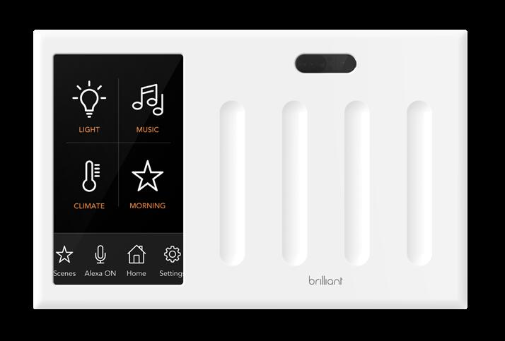
12 9 Secure Faceplate 10 onfigure Brilliant Test the Base and secure the Faceplate. Begin onfiguration Tap the Begin onfiguration button to start the process, and follow the prompts. Side Front Line up the brackets on the Base with the holes on the Faceplate. Press the Faceplate into the brackets and slide down until it clicks. The Faceplate will start up. onnect Wi-Fi Next, it will ask you to connect to Wi-Fi, and it is important to do this so you can access your other smart home devices. onfiguration complete Once the configuration is complete, you can Add Devices to connect Brilliant to your supported smart home devices.


13 Make your whole home Brilliant Once you ve set Brilliant up, it s easy to add more. They ll automatically set themselves up and give you all the benefits of Brilliant throughout your home, including room-to-room video intercom and more. ongratulations, you re done with installation. For help, educational videos, and additional product information visit us: Have a more pressing question? support@brilliant.tech Use the Brilliant App to complete setup. You can download the Brilliant App on your ios or Android device. 1 switch 2 switches 3 switches
14 Removing and replacing the display frame with a new color Step 1 Before proceeding, remove the Faceplate from the Base. Put one hand above it, and grab both sides with the other hand. Then, slide it up and off. Step 2 Next, with two hands and your fingers on the lower edge of the frame, gently pull slightly down on the rear edge of the frame until the clips come loose, and the bottom edge of the frame releases from the display. Step 3 Pull forward. Once the lower edge comes loose, continue to rotate the bottom edge up until you can easily unclip the upper hooks from the top edge of the Faceplate. To attach a new frame, clip the top clips onto the top edge of the Faceplate and then rotate it down until the frame is seated. To ensure the frame is properly clipped on, first squeeze the lower two corners and then squeeze the upper two corners. You can now reattach the Faceplate to the wall. 6+ replaceable color frame options, such as ivory, black, and silver, are available at Side View Side View
15 ontains F ID:VPYLB1DX NOTE: This equipment has been tested and found to comply with the limits for a lass B digital device, pursuant to part 15 of the F Rules. Operation is subject to the following two conditions: (1) This device may not cause harmful interference, and (2) this device must accept any interference received, including interference that may cause undesired operation. These limits are designed to provide reasonable protection against harmful interference in a residential installation. This equipment generates, uses and can radiate radio frequency energy and, if not installed and used in accordance with the instructions, may cause harmful interference to radio communications. However, there is no guarantee that interference will not occur in a particular installation. If this equipment does cause harmful interference to radio or television reception, which can be determined by turning the equipment off and on, the user is encouraged to try to correct the interference by one or more of the following measures: Reorient or relocate the receiving antenna. Increase the separation between the equipment and receiver. onnect the equipment into an outlet on a circuit different from that to which the receiver is connected. onsult the dealer or an experienced radio/tv technician for help. F AUTION hanges or modifications not expressly approved by the party responsible for compliance could void the user s authority to operate the equipment. This transmitter must not be co-located or operated in conjunction with any other antenna or transmitter REV8
How to install your ecobee Switch+
 How to install your ecobee Switch+ Warning Installing this product involves handling high voltage wiring. Each step of the enclosed instructions must be followed carefully. To avoid fire, personal injury,
DOWNLOAD KASA ADD TO KASA INSTALL AND POWER UP SAFETY FIRST
 WELCOME TO KASA Let s get started with your new Wi-Fi Smart Dimmer. Kasa SAFETY FIRST Read and follow all safety precautions in the Kasa app. Ensure power is off at the circuit breaker before removing
SUPERPLANE 2.5 INSTALLATION INSTRUCTIONS WALL/SURFACE BACK MOUNT. A nd Avenue, Unit 1 Oakland,
 INSTALLATION INSTRUCTIONS SUPERPLANE 2.5 WALL/SURFACE BACK MOUNT A 1035 22nd Avenue, Unit 1 Oakland, CA 94606 P 510.489.2530 E TalkToUs@alwusa.com W alwusa.com SP2.5 - Safety & Warnings! 1. Read all instructions.
INSTALLATION INSTRUCTIONS SUPERPLANE 4 WALL MOUNT. A nd Avenue, Unit 1 Oakland, CA P E W alwusa.
 INSTALLATION INSTRUCTIONS SUPERPLANE 4 WALL MOUNT A 1035 22nd Avenue, Unit 1 Oakland, CA 94606 P 510.489.2530 E TalkToUs@alwusa.com W alwusa.com SP4 - Safety & Warnings! 1. Read all instructions. 2. Install
DCH-G020 mydlink Connected Home Hub
 DCH-G020 mydlink Connected Home Hub User s Manual Version 01.0 Oct. 15 th, 2014 Manual Page 1 10/16/2014 1. PRODUCT DESCRIPTION The DCH-G020 is a Connected Home Z-Wave Gateway used to control a variety
INSTALLATION INSTRUCTION Silo Multiples - New Construction Housing MT-4*15, MT-4*10
 IMPORTANT SAFETY INSTRUCTIONS 1. Read all instructions before installing. 2. System is intended for installation by a qualified electrician in accordance with the National Electrical Code and local regulations.
Wireless TFT LCD Monitor
 Wireless TFT LCD Monitor Description Screen Ratio: 16 : 9 Resolution: 800*RGB*480 TV: PAL / NTCS Voltage: 10--28V Rated Capacity: 5W Brightness: 450cd/m2 Contrast: 450:1 Operate temperature: -20~65 Display
Instruction Manual. for Media Monkey. 1
 TM TM Instruction Manual for Media Monkey www.audioaperemote.com 1 Congratulations on acquiring your fine Audio Ape product Let s dive right in, getting up and running is a snap. Here are the components:
SUPERPLANE TM 4 RECESSED SP4R
 Oakland, INSTALLATION INSTRUCTIONS SUPERPLANE TM RECESSED SPR TGrid ATZ Slot n A 1035 22nd Avenue, Unit 1 CA 606 P 510.8.2530 E TalkToUs@alwusa.com W alwusa.com SPR - Safety & Warnings! 1. Read all instructions.
Electronic Emission Notices
 Electronic Emission Notices - - - - - - - - - - - - - - - - - - - - - - - - - - - - - - - - - - - - - - - - - - - - - - - - - - - - - - The following information refers to the Lenovo Active pen. Federal
INSTALLATION MANUAL ES-SUB-WIRELESS-KIT ES-SUB-WIRELESS-RCVR
 INSTALLATION MANUAL ES-SUB-WIRELESS-KIT ES-SUB-WIRELESS-RCVR FCC STATEMENT This equipment has been tested and found to comply with the limits for a Class B digital device, pursuant to Part 15 of the FCC
Clock Radio CR2307 INSTRUCTION MANUAL
 Clock Radio CR2307 INSTRUCTION MANUAL Warnings and Precautions TO PREVENT FIRE OR SHOCK HAZARDS, DO NOT EXPOSE THIS UNIT TO RAIN OR MOISTURE. This symbol, located on back or bottom of the unit, is intended
KANEKA OLED Lighting Module SL (LE-01L, LE-02L, LE-03L, LE-01H, LE-02H, LE-03H) Instruction Manual
 Instruction Manual") KANEKA OLED Lighting Module SL (LE-01L, LE-02L, LE-03L, LE-01H, LE-02H, LE-03H) Instruction Manual Safety Information p. 2 1 Product Overview p. 6 2 Connections and Wiring (when dimming is required) p.
KANEKA OLED Lighting Module SL (LE-01L, LE-02L, LE-03L, LE-01H, LE-02H, LE-03H) Instruction Manual Safety Information p. 2 1 Product Overview p. 6 2 Connections and Wiring (when dimming is required) p.
Wireless Keychain Remote Control
 Wireless Keychain Remote Control Model 3150C Operating Instructions and Owner s Manual Control Garage Door Opener and HomeSettings System from your car Thank you for purchasing the 3150C Wireless Keychain
Remote Control Outlets Operating Instructions
 Remote Control Outlets Operating Instructions - FOR INDOOR OR OUTDOOR USE - IMPORTANT SAFEGUARDS Signal Word Definitions NOTE: These are general definitions only; all may not pertain to the actual product
User s Manual. Twist & Learn Gorilla Pals VTech
 User s Manual Twist & Learn Gorilla Pals 2009 VTech 91-101800-000-000 INTRODUCTION Thank you for purchasing the VTech Jungle Gym Twist & Learn Gorilla Pals! The VTech Jungle Gym Twist & Learn Gorilla
Pser G uide oduct Manual
 ADC-T2000 Hub User Product Guide Manual Hub Product Manual 1 Set Up Required Standard home router with active Internet connection Z-Wave devices to be installed Indicator Lights White Flashing: no internet
Super Switch Indoor Wireless Remote Control Wall Outlets
 Super Switch Indoor Wireless Remote Control Wall Outlets The Remote Control for Living Room, Kitchen & Bedroom Lights, Lamps, Fans and More Item/Art. 770742 Model #: SSW2-3-3322 Set of (3) Indoor Outlets
INSTALLATION INSTRUCTION OCULUX 3 LED - New Construction
 R3BNICA-10 SAFETY INSTRUCTION IMPORTANT: NEVER attempt any work without shutting off the electricity. Read all instructions before installing. System is intended for installation by a qualified electrician
ROUND LIGHTPLANE 1 3D FLUSH
 INSTALLATION INSTRUCTIONS ROUND LIGHTPLANE 1 3D FLUSH RLP1/3D/F Flush Mount Configuration LED A 1035 22nd Avenue, Unit 1 Oakland, CA 94606 P 510.489.2530 E TalkToUs@alwusa.com W alwusa.com Safety & Warnings!
INSTALLATION INSTRUCTIONS Oculux 3.5 Architectural Remodel
 SAFETY INSTRUCTION IMPORTANT: NEVER attempt any work without shutting off the electricity. - Read all instructions before installing. - System is intended for installation by a qualified electrician in
(Wireless Solution)
") Wireless Solution 21.9687.1860 (Wireless Solution) 21.9687.1861 (Lumen Radio) 21.9687.1862 (City Theatrical) Wireless DMX Receivers Installation & User s Manual For use with VL440 Spot, VL770 Spot, VL880
Wireless Solution 21.9687.1860 (Wireless Solution) 21.9687.1861 (Lumen Radio) 21.9687.1862 (City Theatrical) Wireless DMX Receivers Installation & User s Manual For use with VL440 Spot, VL770 Spot, VL880
Schlage Control Smart Locks
 Schlage Control Smart Locks with Engage technology User guide Schlage Control Smart Locks with Engage technology User Guide Contents 3 Warranty 4 Standard Operation 4 Operation from the Inside 4 Operation
Activate Your xfi Pods from the Xfinity xfi Mobile App
 Activate Your xfi Pods from the Xfinity xfi Mobile App This document provides step-by-step instructions on how you can activate your xfi Pods using the Xfinity xfi app for mobile devices. If you have additional
Installation Instructions RF5910
 Installation Instructions RF5910 HES, Inc. 22630 N. 17th Ave. Phoenix, AZ 85027 800-626-7590 1 Product Description Dimensions Orientation Compatibility Access Control Systems Proximity Cards Frequency
XD-V30 Digital Wireless System
 XD-V30 Digital Wireless System Pilot s Handbook Manuel de pilotage Pilotenhandbuch Pilotenhandboek Manual del Piloto 取扱説明書 See www.line6.com/manuals for Advance Guide 40-00-0286 Advanced Users Guide available
Axon Signal Unit Installation Manual
 Introduction The Axon Signal Unit (ASU) is part of a communications platform that interacts with an emergency vehicle s light bar. When the light bar activates, all properly equipped Axon Flex systems
METAL DETECTOR INSTRUCTION GUIDE
 METAL DETECTOR INSTRUCTION GUIDE SET UP STEP 1. STEP 2. Your NATIONAL GEOGRAPHIC detector requires no assembly or tools. Simply remove the detector from the box. Press down the red UNLOCK button on both
Car AVN User Manual. Model Name : LC7F
 Car AVN User Manual Model Name : LC7F 1. Overview and Specifications (1) Overview 1) The Infotainment system provides Infotainment in your car, using the latest technology. See your dealer to have the
Wireless AC Circuit Identifier
 User's Guide Wireless AC Circuit Identifier Models RT30 and RT30-E 99 Washington Street Melrose, MA 02176 Phone 781-665-1400 Toll Free 1-800-517-8431 Visit us at www.testequipmentdepot.com Back to the
Table of Contents. Mounting Diagram.. Wiring Information.. Setting the STR 1000 as a Repeater or a Transmitter. STR 1000 Frequently Asked Questions..
 STR 1000 Series Repeater Installation Manual (V 3.0) Table of Contents MOUNTING Mounting Diagram.. Page 2 WIRING INFORMATION Wiring Information.. Page 3 Setting the STR 1000 as a Repeater or a Transmitter.
802.11a/n/b/g/ac WLAN Module AMB7220
 AboCom 802.11a/n/b/g/ac WLAN Module AMB7220 User s Manual FCC Certification Federal Communication Commission Interference Statement This equipment has been tested and found to comply with the limits for
Murata Bluetooth mesh Node. Installation Guide
 Murata Bluetooth mesh ode Installation Guide Shipped Components Murata Bluetooth mesh ode (BCC2ZZ1PR) ocknut Page 1 Caution Installation and maintenance must be done in accordance with local, state and
EcoSwitch Installation Guide SS8030
 EcoSwitch Installation Guide SS8030 Company Headquarters: Support Information: Sales Information: Telkonet, Inc. Toll Free: +1 (800) 380 9640 Toll Free: +1 (888) 703 9398 10200 W. Innovation Dr. Email:
Radio Link Starter Kit
 Radio Link Starter Kit Installation Manual BARTLETT Instrument Co. 1032 Avenue H Fort Madison, IA 52627 319-372-8366 www.bartinst.com Table of Contents Radio Link Starter Kit Manual... 3 System Requirements...
PowerView Remote Control Guide
 FRONT: OPEN Group 3 Group 4 Group 2 Group 5 LEFT ARROW Sends the middle rail DOWN on Top-Down/Bottom-Up or Duolite products Group 1 Group 6 RIGHT ARROW Sends the middle rail UP on Top-Down/Bottom-Up or
Polycom VoxBox Bluetooth/USB Speakerphone
 SETUP SHEET Polycom VoxBox Bluetooth/USB Speakerphone 1725-49004-001C Package Contents Micro USB Cable 1.21 m 4 ft Carrying Case Security USB Cable 3 m 10 ft L-Wrench Optional Accessories Security USB
User guide. SmartTags. NT3/SmartTagsST25a
 User guide SmartTags NT3/SmartTagsST25a Contents Introduction...3 What are SmartTags?... 3 Getting started... 4 Turning on the NFC function... 4 NFC detection area... 4 Smart Connect... 4 Using SmartTags...
Installation Instructions RF8010/RF8310 RF8010/RF8310: EXTERNAL ANTENNA
 Installation Instructions RF8010/RF8310 HES, Inc. 22630 N. 17th Ave. Phoenix, AZ 85027 800-626-7590 1 Product Description Dimensions Orientation Compatibility Access Control Systems Proximity Cards Frequency
Radio Link Starter Kit
 Radio Link Starter Kit Installation Manual BARTLETT Instrument Co. 1032 Avenue H Fort Madison, IA 52627 319-372-8366 www.bartinst.com Table of Contents Radio Link Starter Kit Manual... 3 System Requirements...
Instruction Sheet. VDM Series. Tilt Low Profile Mount
 Instruction Sheet VDM Series Tilt Low Profile Mount VDM-400-T-LP VDM-600-T-LP VDM-800-T-LP THANK YOU Thank you for purchasing the Vision Display fixed low profile wall mount. Please read these instructions
Wireless Z-Wave Control ZRP-100US Z-Wave Repeater USER MANUAL. Introduction
 Wireless Z-Wave Control ZRP-100US Z-Wave Repeater USER MANUAL Introduction Thank you for choosing ZRP-100 Z-Wave Repeater product! ZRP-100 is a Z-Wave repeater with best RF performance to repeat Z-Wave
Instruction Sheet. VDM Series FIXED & TILT WALL MOUNT
 Instruction Sheet VDM Series FIXED & TILT WALL MOUNT VDM-400-F & VDM-600-F VDM-400-T & VDM-600-T THANK YOU Thank you for purchasing a Vision Display fixed or tilt wall mount. Please read these instructions
User Manual. Product Name:tablet Model Name:TM800A740M Brand Name:NuVision. Manufacture:Shenzhen Vastking Electronic Co.,LTD.
 User Manual Product Name:tablet Model Name:TM800A740M Brand Name:NuVision Manufacture:Shenzhen Vastking Electronic Co.,LTD. FCC Warning This device complies with part 15 of the FCC
Mini Hi-Fi Audio *MFL * SIMPLE MANUAL
 ENGLISH SIMPLE MANUAL Mini Hi-Fi Audio To view the instructions of advanced features, visit http://www.lg.com and then download Owner s Manual. Some of the content in this manual may differ from your unit.
Instruction Sheet. VDM Series FIXED & TILT WALL MOUNT
 Instruction Sheet VDM Series FIXED & TILT WALL MOUNT VDM-800-F VDM-800-T THANK YOU Thank you for purchasing the Vision Display fixed and tilt wall mounts. Please read these instructions thoroughly before
StreamStick by NAV-TV is a USB-powered, HI-FI Bluetooth 4.0 audio streaming module for automotive and home use. Make ANY stereo (equipped with AUX
 StreamStick by NAV-TV is a USB-powered, HI-FI Bluetooth 4.0 audio streaming module for automotive and home use. Make ANY stereo (equipped with AUX input) a Bluetooth-audio receiver! Using the StreamStick
SAFETY WARNINGS AND GUIDELINES
 SAFETY WARNINGS AND GUIDELINES Turn off and unplug all equipment prior to making electrical connections, including speaker wire connections. Reduce the volume level prior to making any change to the audio
CRUX II/BTGPS USER GUIDE. Model:D1598
 CRUX II/BTGPS USER GUIDE Model:D1598 0 Federal Communication Commission Interference Statement This equipment has been tested and found to comply with the limits for a Class B digital device, pursuant
APM 6998 WiFi Module Manual
 Host Revision Information APM 6998 WiFi Module Manual Host Hardware Revision Host Module Driver Version Module Hardware Revision T3x Rev D1 v8.1.4.4 001E Host PCB Design Guidelines The following guidelines
v Pairing Instructions for: GENERAL MOTORS REPLACEMENT FLIP KEYS
 v1.0618 Pairing Instructions for: GENERAL MOTORS REPLACEMENT FLIP KEYS PAIRING INSTRUCTIONS To successfully perform these pairing instructions, an original, working key must be present. If an original,
FOR AVLEX ONLY MT-24A. User Guide. 2.4 GHz Digital Stationary Transmitter
 2.4 GHz Digital Stationary Transmitter User Guide All rights reserved. MN 017/05 Do not copy or forward without prior approvals MIPRO. Specifications and design subject to change without notice. 2 CE5
802.11n, 2.4G 1T1R Wireless LAN PCI Express Half Mini Card
 802.11n, 2.4G 1T1R Wireless LAN PCI Express Half Mini Card WN6605LH Realtek RTL8191SE User s Manual Ben J. Chen 3/4/2010 Federal Communication Commission Interference Statement This equipment has been
USB WiFi for Projector
 USB WiFi for Projector User s Manual Brand:acer lmodel:uwa2 Rev. 1.01 FCC statement This equipment has been tested and found to comply with the limits for a Class B digital device, pursuant to Part 15
12V Victor 888 User Manual
 The Victor speed controllers are specifically engineered for robotic applications. The high current capacity, low voltage drop, and peak surge capacity make the Victor ideal for drive systems while its
P A T. Play Dome. Product features may vary from picture above.
 L E A R N I N G P A T T E R N S Play Dome Product features may vary from picture above. Model Number: B0003 Please keep this instruction sheet for future reference, as it contains important information.
Instruction Sheet VDM-200-T. Tilt Wall Mount
 Instruction Sheet VDM-200-T Tilt Wall Mount THANK YOU Thank you for purchasing the VDM-200-T tilt wall mount. Please read these instructions thoroughly before installing or assembling this product. PRODUCT
Door/Window Sensor User Manual HKWL DWS02W
 Door/Window Sensor User Manual HKWL DWS02W 1. PRODUCT OVERVIEW HKWL DWS02W is a Wi Fi wireless Door/Window sensor, you can monitor the status of your door/window in real time through your smart phone.
SwingTracker User Guide. Model: DKST02 User Guide
 SwingTracker User Guide Model: DKST02 User Guide PACKAGE CONTENTS What Comes in the Box USING YOUR SWINGTRACKER SENSOR Attach SwingTracker Sensor to your Bat Turn On your Sensor Pair your Sensor Remove
Hi-Fi Shelf System *MFL * SIMPLE MANUAL
 ENGLISH SIMPLE MANUAL Hi-Fi Shelf System Please read this manual carefully before operating your set and retain it for future reference. To view the instructions of advanced features, visit http://www.lg.com
MEQ15BT. INSTALLATION / OWNER'S MANUAL Wireless Smart EQ Processor FCC ID : GJW-SBT504 IC ID : 4038A-SBT504
 MEQ15BT Wireless Smart EQ Processor FCC ID : GJW-SBT504 IC ID : 4038A-SBT504 Preparation Please read the entire manual before installation. It is highly recommended that your Smart EQ be installed by a
On-Line Cardio Theater Wireless Digital Transmitter Installation and Instruction Manual
 On-Line Cardio Theater Wireless Digital Transmitter Installation and Instruction Manual Full installation instructions accompany your Cardio Theater equipment order. This On-Line version of our Installation/Instruction
Black Oak / Light Oak / Cherrywood Wireless Panel Speaker
 4015115/4015116/4015117 Black Oak / Light Oak / Cherrywood Wireless Panel Speaker With Infrared Remote Control USER GUIDE For use with: Introduction These 900 MHz stereo wireless speaker system uses the
BT11 Hardware Installation Guide
 Overview The Mist BT11 delivers a BLE Array AP with internal antennas that are used for BLE based location. 1 Understanding the Product Included in the box: BT11 Mounting bracket with mounting hardware
CARE +MAINTENANCE Cleaning Important Safety Instructions Water Drop Heat Battery Charging Repair
 CARE +MAINTENANCE Cleaning 1. Wipe with a dry cloth. 2. Rinse with fresh water after exposure to soap, chlorine or seawater. 3. Do not use solvents, chemicals, cleaning solutions, alcohol, ammonia or abrasives.
Smart Ship Learn & Go
 User s Manual Smart Ship Learn & Go tm 3-6 Years Disney Visit DisneyJunior.com 2012 Vtech Printed in China 91-001655-000 Dear Parent, At VTech, we know how important the first day of school is for your
Regulatory Compliance Statement
 Regulatory Compliance Statement EU Declaration of Conformity The declaration of conformity may be consulted at www.kobo.com/userguides SAR Limits The exposure standard for wireless devices employs a unit
Thanks for choosing Phyn
 Homeowner guide Thanks for choosing Phyn We sincerely appreciate you bringing Phyn into your home, and promise to be a good houseguest. Phyn is a smart water assistant that starts to learn about your plumbing
Model: VR-1A INSTALLATION AND OPERATING INSTRUCTIONS
 INTRODUCTI Model: VR-1A INSTALLATI AND OPERATING INSTRUCTIS SINGLE-FUNCTI WIRELESS CTROL SYSTEM FOR OPERATING HI/LOW SERVO MOTOR IF YOU CANNOT READ OR UNDERSTAND THESE INSTALLATI INSTRUCTIS DO NOT ATTEMPT
Icon Description UP ( ) 1 BACK ( ) 4 PAGE ( )
 1 BACK ( ) 4 PAGE ( )") EN 1 1 BACK ( ) Press to return to the previous page or cancel an operation. When recording, press to pause recording. Press it again to stop recording. 2 LAP/OK ( ) In Menu, press to enter or confirm
EN 1 1 BACK ( ) Press to return to the previous page or cancel an operation. When recording, press to pause recording. Press it again to stop recording. 2 LAP/OK ( ) In Menu, press to enter or confirm
USER MANUAL MODEL: BM-162
 USER MANUAL MODEL: BM-162 Parents Unit: A. Name Power ON/OFF Key Music Key PTT Key Volume - Key Microphone Power & Low battery indicator LCD display Volume + Key Night Light and torch Key Speaker -Belt
Disclaimers. Important Notice
 Disclaimers Disclaimers Important Notice Copyright SolarEdge Inc. All rights reserved. No part of this document may be reproduced, stored in a retrieval system, or transmitted, in any form or by any means,
TOUCH LEARNING SYSTEM
 User s Manual TOUCH LEARNING SYSTEM Dear Parent, At VTech, we know how much you enjoy staying on top of the hottest trends and having the most high-tech gadgets around. We also know that your kids feel
or call
 Email service@acecasual.com or call 1 FEATURES A-Control Panel A1-Vibration adjustment A2-Bass Volume Adjustment A3-Volume Adjustment A4-Audio Input Jack A5-Audio Output Jack for linking multiple chairs
16+ HS300. Instructions for use. One Key Start/One Key Landing Function Headless Mode / One Key Return Altitude Hold Mode
 16+ HS300 Instructions for use One Key Start/One Key Landing Function Headless Mode / One Key Return Altitude Hold Mode usa@holystone.com ca@holystone.com By scanning the QR code or searching Holy Stone
Roll Rite Automated Tarp System Remote Control Owner s Guide
 Roll Rite Automated Tarp System Remote Control Owner s Guide On behalf of Roll Rite, we wish to thank you for your purchase of our Automated Tarp Systems Our Mission Roll Rite designs and manufactures
Mini Hi-Fi Audio *MFL * SIMPLE MANUAL
 ENGLISH SIMPLE MANUAL Mini Hi-Fi Audio To view the instructions of advanced features, visit http://www.lg.com and then download Owner s Manual. Some of the content in this manual may differ from your unit.
Radio Micro Force Manual v1.1
 Radio Micro Force Manual v1.1 Preston Cinema Systems 1659 Eleventh Street Santa Monica CA 90404 tel 310-453-1852 fax 310-453-5672 www.prestoncinema.com Table of Contents 1. Description 2. Operation 3.
FCC Certification Notice: IC Certification
 Users Manual VP4450 FCC Certification This device complies with Part 15 of the FCC Rules. Operation is subject to the following two conditions: (1) This device may not cause harmful interference, and (2)
YES 12 Charging Wall Cabinet for Mini-laptops
 Built with Anthro-DNA Owner's Manual for YES 12 Charging Wall Cabinet for Mini-laptops Part # YESMLCGMPW Components at a Glance 7 1 9 8 2 4 5 11 6 10 3 Front of Cabinet (closed) 1. Locking front door to
Getting the most out of your
 Getting the most out of your #WhatWillYouCreate? SLOW FAST Hello Please do not throw these instructions away. (We worked really hard to make sure they were as useful and readable as possible!) thedoodler.com
Focus Iris Manual Ver 1.1
 Focus Iris Manual Ver 1.1 Preston Cinema Systems 1659 Eleventh Street Santa Monica CA 90404 tel 310 453 1852 fax 310 453 5672 www.prestoncinema.com Table of Contents 1. Description 2. Operation 3. Specifications
260X190mm/105 克铜版纸 / 黑白印刷
 260X190mm/105 克铜版纸 / 黑白印刷 5172301 1 FEATURES A-Control Panel A1-Bass Volume Adjustment A2-Volume Adjustment A3-Audio Input Jack A4-Audio Output Jack for linking multiple chairs A5-Wire mode / Bluetooth
MOVADO.COM/SMARTSUPPORT
 LANGUAGES ENGLISH... 3 FRANÇAIS... 4 ESPAÑOL... 5 REGULATORY INFORMATION... 6 MOVADO CONNECT POWERED BY ANDROID WEAR DOWNLOAD THE APP & GET STARTED AT MOVADO.COM/SMARTSUPPORT 3 MOVADO CONNECT POWERED BY
45 AND 60 UNIVERSAL REMOTE INSTALLATION AND OPERATION INSTRUCTIONS
 45 AND 60 UNIVERSAL REMOTE INSTALLATION AND OPERATION INSTRUCTIONS 1, RECEIVER INSTALLATION The receiver can be installed as either a wall mount 0 or a appliance mount. Depending on your application, follow
Mini Hi-Fi System *MFL * SIMPLE MANUAL
 ENGLISH SIMPLE MANUAL Mini Hi-Fi System Please read this manual carefully before operating your set and retain it for future reference. To view the instructions of advanced features, visit http://www.lg.com
Transponder Reader TWN4 MultiTech 3 Quick Start Guide
 Transponder Reader TWN4 MultiTech 3 Quick Start Guide Rev. 1.0 1. Introduction The transponder reader TWN4 is a device for reading and writing RFID transponders. There are different versions of TWN4 devices
testosaveris 2 User Manual testo Saveris 2Introduction
 testosaveris 2 User Manual testo Saveris 2Introduction testo Saveris 2 system is upgrading product basing on testo Saveris system. In original system, wireless probes transfer measurement data to Saveris
S5-ADU. Front... 4 Rear... 4
 Trantec ANTENNA DISTRIBUTOR INSTRUCTION MANUAL S5-ADU Thank you for purchasing TRANTEC Antenna Distributor. Please carefully follow the instructions in this manual to ensure long, trouble-free use of your
Need Help? SA /
 1 FEATURES A-Control Panel A1-Vibration adjustment A2-Bass Volume Adjustment A3-Volume Adjustment A4-Audio Input Jack A5-Audio Output Jack for linking multiple chairs A6-Wire mode / Bluetooth mode Switch
User s Manual. Learn & Go Tablet TM VTech Printed in China 美
 User s Manual Learn & Go Tablet TM 2011 VTech Printed in China 91-001619-003 美 Dear Parent, At VTech, we know how important the first day of school is for your child. To help prepare preschoolers for this
To learn more about V.Reader and other VTech toys, visit
 INTERACTIVE E-READING SYSTEM User s Manual Dear Parent, At VTech, we know how important reading is for your child s development. We want to introduce children to reading in a dynamic, engaging way that
Parent's Guide US
 Parent's Guide 91-003220-004 US INTRODUCTION Thank you for purchasing the Explore & Write Activity Desk! The Explore & Write Activity Desk features an interactive desktop with activity cards that introduce
Doc Rev - B. INSTALLATION AND PROGRAMMING INSTRUCTIONS FOR THE ClikCard NARROW BAND RESIDENTIAL GARAGE DOOR RECEIVER
 Doc - 6001238 Rev - B INSTALLATION AND PROGRAMMING INSTRUCTIONS FOR THE ClikCard NARROW BAND RESIDENTIAL GARAGE DOOR RECEIVER TABLE OF CONTENTS PART 1 INTRODUCTION AND BASICS...1 A. MOUNTING THE RECEIVER
Disney elements Disney
 User s Manual TOUCH LEARNING SYSTEM TM Disney elements Disney Dear Parent, At VTech, we know how much you enjoy staying on top of the hottest trends and having the most high-tech gadgets around. We also
User Guide. Do not copy or forward without prior approvals MIPRO. Specifications and design subject to change without notice.
 User Guide ACT-70H / ACT-71Ha ACT-71H / ACT-72H All rights reserved. MN 016/01 Do not copy or forward without prior approvals MIPRO. Specifications and design subject to change without notice. 2 CE5 2
STI REPEATER. BEFORE YOU START Refer to this drawing to become familiar with all the parts. Installation and Operation Manual.
 Installation and Operation Manual STI REPEATER Model: STI-34109 Thank you for purchasing this fine product. Your satisfaction is very important to us. Please read this manual carefully to get the most
EARNING APP T THE LEARNING APP ABLET
 User s Manual TABLET APP LEARNING THE 2014 VTech Dear Parent, At VTech, we know how much you enjoy staying on top of the hottest trends and having the most high-tech gadgets around. We also know that your
CCR24T CCR24R. User s Guide WIRELESS TRANSMITTER SYSTEM WARRANTY SERVICE CARD WARRANTY CARD
 WARRANTY SERVICE CARD WARRANTY CARD PRODUCT NAME Wireless Transceiver System PERIOD MODEL NAME CCR24GEN YEAR PURCHASE DATE.. 200_ From the date of WARRANTY PERIOD.. 200_ purchase. CUSTOMER S ADDRESS :
Lenovo regulatory notice for wireless adapters
 Lenovo regulatory notice for wireless adapters - - - - - - - - - - - - - - - - - - - - - - - - - - - - - - - - - - - - - - - - This manual contains regulatory information for the following Lenovo products: