Project 14361: Engineering Applications Lab
|
|
|
- Hannah Leonard
- 5 years ago
- Views:
Transcription


1 Project 14361: Engineering Applications Lab

2 Jennifer Leone Larry Hoffman Angel Herrera Henry Almiron Saleh Zeidan Dirk Thur TEAM MEMBERS Industrial Engineer Team Lead Electrical Engineer Electrical Engineer Mechanical Engineer Mechanical Engineer Mechanical Engineer
3 Project Description Current State Students in the Mechanical Engineering department currently take a sequence of experimental courses, one of which is MECE 301 Engineering Applications Lab. Desired State 2-3 modules used to provide a set of advanced investigative scenarios that will be simulated by theoretical and/or computational methods. Project Goals Create modules to instruct engineering students Expose students to unfamiliar engineering ideas Constraints Stay within budget

4 Customer Needs and Requirements

5 Module Requirements
6 Railgun Background An energy conversion system that uses electrical energy and converts it into mechanical energy to launch a projectile. Consists of parallel pair of conducting rails with an armature connecting them to complete the circuit and launch the projectile. Magnitude of the force vector determined by calculating the strength of the magnetic field through the Biot-Savart Law, and then finding the Lorentz force to determine the resultant force vector.


7 Railgun Design Concept


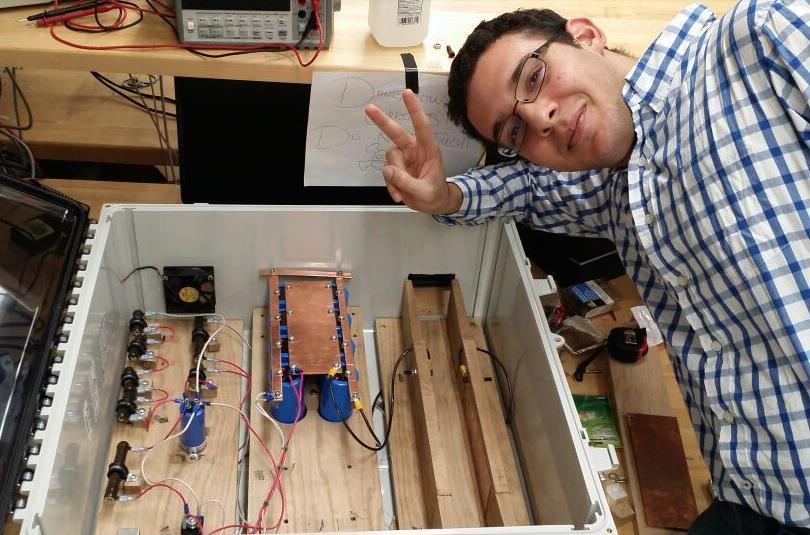
8 Railgun Build Process


9 Railgun Module Design

10 Railgun Module Video

11 Railgun Module Testing
12 Railgun Student Experience 1) Student sets up system by plugging in variac into wall outlet. Followed by using the custom made power cord to connect the variac to the railgun module. 2) Student adjust knob on variac to desired input before turning on the variac. Student also checks to make sure that the charging circuit switch is set to on position and the bleeding circuit switch is on the off position. Student also moves the fan switch to the on position. 3) Student hits on switch on the variac to begin charging the capacitor bank. 4) During charge up student checks on voltage value in capacitor bank displayed on a voltmeter attached to the capacitor bank. 5) Once charge up is completed student moves charging circuit switch to off position and turns off variac as well. 6)The student then uses the pushing stick to propel the object into the rails and see the car accelerate due to the magnetic fields produced. 6b) If the student for whatever reason desires to release the stored energy in the capacitor back without passing the object through the rails he/she must move the bleeding circuit switch to the on position. Student then waits for a bit and watches the voltmeter to see when the capacitor bank is depleted to safe levels. 7) If the student launches the object then with the help of a camera the students would derive the speed of the object while before and after passing through the rails. After the speeds have been calculated the student will compare the actual results with the theoretical results to determine how much energy from the capacitors was transferred into the object. 8) If the student wished to perform additional launches steps 1 through 6 will be repeated.
13 Capacitor Bank Charge Up Times Input Voltage to Capacitor Bank (Volts) 2.04V 4.07V 6.11V 8.15V 10.19V Charge Times (Sec) Average Time (Sec) 3.54sec 8.03sec 12.21sec 17.27sec 22.32sec 4.09sec 6.79sec 11.53sec 17.33sec 22.65sec 3.53sec 7.05sec 11.63sec 16.61sec 22.73sec 3.82sec 7.50sec 12.12sec 16.93sec 22.41sec 3.90sec 7.08sec 11.93sec 16.74sec 22.67sec 4.36sec 6.70sec 11.80sec 17.08sec 22.70sec 3.87sec 7.19sec 11.87sec 16.99sec 22.58sec
14 Capacitor Bank Discharge Times Input Voltage to Capacitor Bank (Volts) 2.04V 4.07V 6.11V 8.15V 10.19V Discharge Times (Sec) Average Time (Sec) 20.94sec 27.09sec 32.59sec 37.25sec 41.61sec 18.22sec 27.38sec 33.05sec 36.94sec 41.47sec 18.83sec 27.10sec 32.66sec 38.02sec 41.72sec 17.77sec 27.76sec 32.37sec 38.14sec 41.54sec 18.26sec 26.58sec 32.70sec 38.39sec 41.58sec 18.73sec 26.65sec 33.04sec 38.28sec 42.52sec 18.79sec 27.09sec 32.74sec 37.84sec 41.74sec
15 Dissipated Voltage (V) Time (s) Average Time vs. Initial Voltage Lower Ramp Upper Ramp Initial voltage (V) 12 Average Voltage Dissipated vs. Initial Voltage Lower Ramp Upper Ramp Initial Voltage (V)
16 Problem # Identifying & Selecting Problem PSP 1 No car design tested has been able to clear rails Analyzing Problem PSP 2 Generating Potential Solutions PSP 3 Selecting & Planning Solution PSP 4 Implementing Solution PSP 5 Evaluating Solution PSP 6 R1 R2 R3 Y4 Y5 G6 Push team to complete more car designs, come up Have multiple designs and with a series of parameters Parameters will be tested in prototypes but none seem to Parameters will be tested to determine the root cause order to determine the best complete track way cars between Weeks of what materials, shapes projectile or car for the railgun were designed and sizes will work best in rails Debugging car does not move through rails as expected Rail dimensions and spacing have an impact on the velocity and acceleration of the car With the current projectile, rod must be placed on ramp PROBLEM TRACKING LIST AS OF 12/3/2015 Car is experiencing too much friction and has too much mass to it. Based on the tests conducted by the team, there is a correlation between longer contact length with the rails and the rail orientation In order to start projectile motion, need to be inside the enclosure to let go of the projectile Design new concepts for a smaller and lighter car to launch. Alter the current design to match what test made the car move the fastest and farthest -Keep the same layout as originally designed and live with current velocity and acceleration Leave as is, come up with new ramp design outside of enclosure, use a different kind of projectile Run series of tests to determine what variables will make the car go the farthest and launch as the team had envisioned Alter the current design to match the test that made the car have the highest velocity and acceleration Parameters will be tested in order to determine the best projectile or car for the railgunfrom there it will be determined where to place the ramp Parameters will be tested between Weeks Added magnets to the design, magnets will be placed on top of the car; rails will be shortened in length. The magnet will be the part of the car to roll over the rails - design to be completed during weeks Parameters will be tested between Weeks TBD- Will be shown at customer demo in Jan 2015 TBD- Will be shown at customer demo in Jan 2015 TBD- Will be shown at customer demo in Jan 2015 TBD- Will be shown at customer demo in Jan The rails and the rod used to bridge them degrade after each use due to spot welding The current system setup requires the rail-to-car connectors to roll across the top of the rails, which requires tight tolerances between the height of the rails and the rail-to-car connector. -Return to car rolling parallel to the rods. -Abandon Car. -Some method of forcing rod onto rails that won't ruin both The team has decided to set aside the car and use a rolling projectile instead. -A new ramp and track to be designed for the projectile were created TBD- Will be shown at customer demo in Jan 2015
17 The Next Steps: Completing Railgun Module Make a reliable tool to guarantee a consistent initial velocity and release angle Conduct tests to produce quantifiable data about the effects of the parameters listed below: System Variable Description Testing Method Projectile shape Changing shape of the projectile- change the shape of its magnetic field and the way it interacts with the rails. Proposed shapes include a rod, a sphere, and a dumbbell Strength of magnets Rail Geometry Stronger the magnets used, the stronger the resultant magnetic field, which should correlate to a greater electromagnetic force Changing the geometry of the rails will change their resistivity, as well as effect the shape of their magnetic fields Make projectiles of different shapes, shoot them down the track, and record their times. Vary the number of magnets on the projectile, shoot them down the track, and record their time. Make rails of different geometries, shoot a projectile down them, and record their times.
 when interacted upon by the propeller, which results in a force in the opposite direction to the flow of air.")
18 Thrust Module Concept Using a combination of motor, speed controller and load cell the thrust created by a propeller can be tested and quantitatively compared to theoretical models. Thrust is due to the momentum change in the fluid ( in this case air) when interacted upon by the propeller, which results in a force in the opposite direction to the flow of air.


19 Thrust Module Concept


20 Thrust Module

21 Thrust Module Video
22 Thrust Module Student Experience Walk into lab Insert and tighten propeller Close module door and connect batteries Turn on computer and connect load cell and DAQ Devise controlling the speed controller Run Lab view code to cycle motor and record data Safely turn system down, Save Data, Disconnect batteries, and remove propeller
23 Thrust Module Test Data
24 Thrust Module Test Data
25 Thrust Problem Tracking List as of 12/3/2015 Proble m # 1 2 Identifying & Selecting Problem PSP 1 Speed Controller died after testing Analyzing Problem PSP 2 Generating Potential Solutions PSP 3 Selecting & Planning Solution PSP 4 Implementing Solution PSP 5 Evaluating Solution PSP 6 R1 R2 R3 Y4 Y5 G6 One parameter that was not controlled Replace Speed during this test was Controller. Prepare the rate at which I one page technical New Requisition form was changing the summary of prop size signed and new OUTLOOK: Module PWM; is it possible vs. required current speed controller will will function the way that too rapid a vs. speed controller arrive by the end of it was designed change can cause options. Have a team week 13 to be tested relatively high summary (prop size instantaneous vs. speed controller) currents? Current propellers sized too large for module Potentially one of the reasons why the speed controller died; Consulted with other engineers and hobby shop to confirm this was a problem for the module -Replace current props with smaller size to fit the scale of the design -Resize the module to fit larger propellers Called company to exchange propellers on December 2nd. Can be tested once parts are in house OUTLOOK: Propellers will fit module and function the way it was designed to TBD - snow storm delayed speed controller shipment; In house on 12/2/2015 and will be tested for week 15 TBD once the new props comes in by the end of week 18
26 The Next Steps- How to Complete Thrust Module Use Labview to: Run the motor through a preset cycle Record thrust data (forces, loads, etc.) while controlling the motor Install a new ESC and run module using a variety of props Compare to theoretical calculations of propeller diameter and pitch vs thrust.
27 Lessons Learned Thoroughly review the budget prior to buying anything Always double check your positive and negative terminals when connecting to a battery. Always know where the nearest fire extinguisher is. Document all changes made and data collected throughout the project process. How to work together as a team

28 Acknowledgements The MSD Team would like to thank Professor Wellin, Professor Slack, Professor Venkataraman, Vanessa Mitchell, Tyler Burns, Robert Kraynik, and Jan Maneti for all their support, advice, and time for the duration of this project. Finally, the team would like to thank Professor Hanzlik for all his guidance, advice and support to complete our deliverables. You gave us the strength to believe in ourselves and gave us life lessons that we will never forget.


29 QUESTIONS?
Electronic Speed Controls and RC Motors
 Electronic Speed Controls and RC Motors ESC Power Control Modern electronic speed controls regulate the electric power applied to an electric motor by rapidly switching the power on and off using power
Projectile Motion. Equipment
 rev 05/2018 Projectile Motion Equipment Qty Item Part Number 1 Mini Launcher ME-6800 1 Metal Sphere Projectile 1 and 2 Meter Sticks 1 Large Metal Rod ME-8741 1 Small Metal Rod ME-8736 1 Support Base ME-9355
Engineering Diploma Resource Guide ST150 ETP Research & Design (Engineering)
") Engineering Diploma Resource Guide ST50 ETP Research & Design (Engineering) Introduction Whether we are looking to improve a current system or design a completely new product for the market place, we have
Engineering Diploma Resource Guide ST50 ETP Research & Design (Engineering) Introduction Whether we are looking to improve a current system or design a completely new product for the market place, we have
Simulating the Difference between a DES and a Simple Railgun using SPICE
 Simulating the Difference between a DES and a Simple Railgun using SPICE S. Hundertmark French-German Research Institute of Saint-Louis, France arxiv:1602.04973v1 [physics.plasm-ph] 16 Feb 2016 Abstract
Relationship to theory: This activity involves the motion of bodies under constant velocity.
 UNIFORM MOTION Lab format: this lab is a remote lab activity Relationship to theory: This activity involves the motion of bodies under constant velocity. LEARNING OBJECTIVES Read and understand these instructions
Parametric Analyses Using a Computational System Model of an Electromagnetic Railgun
 Parametric Analyses Using a Computational System Model of an Electromagnetic Railgun NDIA Joint Armaments Conference: Unconventional & Emerging Armaments Session 16 May 2012 Ms. Vanessa Lent Aerospace
18600 Angular Momentum
 18600 Angular Momentum Experiment 1 - Collisions Involving Rotation Setup: Place the kit contents on a laboratory bench or table. Refer to Figure 1, Section A. Tip the angular momentum apparatus base on
A 11/89. Instruction Manual and Experiment Guide for the PASCO scientific Model SF-8616 and 8617 COILS SET. Copyright November 1989 $15.
 Instruction Manual and Experiment Guide for the PASCO scientific Model SF-8616 and 8617 012-03800A 11/89 COILS SET Copyright November 1989 $15.00 How to Use This Manual The best way to learn to use the
MARBLE RACING. Practice Calculating Speed
 MARBLE RACING Practice Calculating Speed Problem How does the angle of the ramp affect the marble s speed? Materials Ruler Meter stick Masking Tape 5 Books Marble Timer Protractor Procedure 1. Mark a finish
Projectiles: Target Practice Student Version
 Projectiles: Target Practice Student Version In this lab you will shoot a chopstick across the room with a rubber band and measure how different variables affect the distance it flies. You will use concepts
Activity 1 Position, Velocity, Acceleration PHYS 010
 Name: Date: Partners: Purpose: To investigate and analyse basic properties of motion using a Vernier Go! Motion Detector and logging software. Materials: 1. PC with Logger Lite Software installed. 2. Go!
In-Depth Tests of Faulhaber 2657CR012 Motor
 In-Depth Tests of Faulhaber 2657CR012 Motor By: Carlos Arango-Giersberg May 1 st, 2007 Cornell Ranger: Autonomous Walking Robot Team Abstract: This series of tests of the Faulhaber 2657CR012 motor were
Determining the Relationship Between the Range and Initial Velocity of an Object Moving in Projectile Motion
 Determining the Relationship Between the Range and Initial Velocity of an Object Moving in Projectile Motion Sadaf Fatima, Wendy Mixaynath October 07, 2011 ABSTRACT A small, spherical object (bearing ball)
Virtual Experiments as a Tool for Active Engagement
 Virtual Experiments as a Tool for Active Engagement Lei Bao Stephen Stonebraker Gyoungho Lee Physics Education Research Group Department of Physics The Ohio State University Context Cues and Knowledge
Taking a closer Look at the Demonstration Equipment October 24, 2006
 Taking a closer Look at the Demonstration Equipment October 24, 2006 This is the classic photo of E.V. Gray s Popping Coil Demonstration apparatus. This can be found on Peter Lindemann s web site. This
Lab 5: EC-3, Capacitors and RC-Decay Lab Worksheet
 , Capacitors and RC-Decay Lab Worksheet Name Your TA will use this sheet to score your lab. It is to be turned in at the end of lab. You must use complete sentences and clearly explain your reasoning to
12 Projectile Motion 12 - Page 1 of 9. Projectile Motion
 12 Projectile Motion 12 - Page 1 of 9 Equipment Projectile Motion 1 Mini Launcher ME-6825A 2 Photogate ME-9498A 1 Photogate Bracket ME-6821A 1 Time of Flight ME-6810 1 Table Clamp ME-9472 1 Rod Base ME-8735
Primary Resistor Starters with Time Relays
 Exercise 6-3 Primary Resistor Starters with Time Relays EXERCISE OBJECTIVE Understand how a time relay can be used jointly with primary resistor starters. DISCUSSION Primary resistor starters are used
OPERATION MANUAL. Model 1010 TE Survey Meter. August Health Physics Instruments 330 South Kellogg Ave, Suite D Goleta, CA 93117
 OPERATION MANUAL Model 1010 TE Survey Meter August 1998 Health Physics Instruments 330 South Kellogg Ave, Suite D Goleta, CA 93117 GENERAL INFORMATION This instrument is manufactured in the United States
System Definition Review. Splat Group 3
 System Definition Review Splat Group 3 The Members Raleigh Killen Project Manager Payload Accommodation & Deployment System (PADS) Stephen Beck, Danielle Newton, Tanner Shaw Balloon Deployment & Retraction
Motions and Forces Collision I
 Motions and Forces Collision I Discovery Question What happens when two objects collide? Introduction Thinking About the Question Materials Safety Trial I: Weighing the cart with the Force probe Trial
Electromagnetic Can Crusher Victoria Meadows and Matthew Kundrock Advisor: Dr. Gore. Introduction
 Electromagnetic Can Crusher Victoria Meadows and Matthew Kundrock Advisor: Dr. Gore Introduction Our Capstone Project was to build an Electromagnetic Can Crusher, a device that will crush an aluminum can
P15051: Robotic Eye for Eye Tracker
 P15051: Robotic Eye for Eye Tracker Andrew Drogalis Mechanical Engineer Tim O Hearn Mechanical Engineer Katie Hardy Daniel Webster Jorge Gonzalez Abstract: A robotic eye was constructed for the purpose
Electrical Measurements
 Electrical Measurements INTRODUCTION In this section, electrical measurements will be discussed. This will be done by using simple experiments that introduce a DC power supply, a multimeter, and a simplified
FD 125 Large-Format Card Cutter
 FD 125 Large-Format Card Cutter 3/201 OPERATOR MANUAL Page 2 Table of Contents SAFETY PRECAUTIONS... 4 Introduction... 5 Specifications... 5 Accessories... 5 Major Components and Assemblies... 6 Control
NEULOG PHOTO GATE LOGGER SENSOR GUIDE
 NeuLog photo gate logger sensor NUL-209 Part# NL-2090 The NeuLog photo gate sensor can be used for any science experiment which involves taking accurate velocity and/or acceleration measurements especially
NEULOG PHOTO GATE LOGGER SENSOR GUIDE
 NeuLog photo gate logger sensor NUL-209 The NeuLog photo gate sensor can be used for any science experiment which involves taking accurate velocity and/or acceleration measurements especially in the field
PRELIMINARY DESIGN REPORT
 PRELIMINARY DESIGN REPORT Dodge This! DODGERS: Cristobal Rivero Derek Fairbanks 1/27/2009 Abstract: Our project is to develop an automatic dodge ball game. It consists of an infrared video camera, computer,
Simple-H User Manual
 Simple-H User Manual Thank you for your purchase of the Robot Power Simple-H. This manual explains the features and functions of the Simple-H along with some tips for successful application. Before using
Suppression Techniques using X2Y as a Broadband EMI Filter IEEE International Symposium on EMC, Boston, MA
 Suppression Techniques using X2Y as a Broadband EMI Filter Jim Muccioli Tony Anthony Dave Anthony Dale Sanders X2Y Attenuators, LLC Erie, PA 16506-2972 www.x2y.com Email: x2y@x2y.com Bart Bouma Yageo/Phycomp
Hall Effect User Manual v1.0
 Ecopia HMS-5300 (80 350K) Hall Effect User Manual v1.0 Woodall Research Group, Ghausi 1123 Kyle Montgomery, PhD kmontgomery.net 7/2/2013 Table of Contents Specs... 2 Mfg Point of Contact... 2 Sample Loading...
EC-3: Capacitors and RC-Decay
 Your TA will use this sheet to score your lab. It is to be turned in at the end of lab. You must use complete sentences and clearly explain your reasoning to receive full credit. EC-3, Part I: Do not do
Precalculations Individual Portion Introductory Lab: Basic Operation of Common Laboratory Instruments
 Name: Date of lab: Section number: M E 345. Lab 1 Precalculations Individual Portion Introductory Lab: Basic Operation of Common Laboratory Instruments Precalculations Score (for instructor or TA use only):
. B 0. (5) Now we can define, B A. (6) Where A is magnetic vector potential. Substituting equation (6) in to equation (2),
 Now we can define, B A. (6) Where A is magnetic vector potential. Substituting equation (6) in to equation (2),") Research Paper INVESTIGATING THE EFFECT OF CURRENT SHAPE ON RAIL GUN DESIGN AT TRANSIENT CONDITIONS Murugan.R 1, Saravana Kumar M.N 2 and Azhagar Raj.M 3 Address for Correspondence 1 Professor, Department
Research Paper INVESTIGATING THE EFFECT OF CURRENT SHAPE ON RAIL GUN DESIGN AT TRANSIENT CONDITIONS Murugan.R 1, Saravana Kumar M.N 2 and Azhagar Raj.M 3 Address for Correspondence 1 Professor, Department
Introduction to High-Speed Power Switching
 Exercise 3 Introduction to High-Speed Power Switching EXERCISE OBJECTIVE When you have completed this exercise, you will be familiar with the concept of voltage-type and current-type circuits. You will
Internal Model of X2Y Chip Technology
 Internal Model of X2Y Chip Technology Summary At high frequencies, traditional discrete components are significantly limited in performance by their parasitics, which are inherent in the design. For example,
Assembly Instructions: Kit #5
 Assembly Instructions: Kit #5 1. Insert the T-pin into one of the caps. 2. Insert the rotor core into the same cap as shown below. Apply some pressure to push the rotor core approximately 1/2" (10-12 mm)
Size 23 Single Stack Size 23 Double Stack. 30-in (760 mm) 225 lbs (1,000 N) lbs-ft (30.5 Nm) lbs-ft (26.25 Nm) lbs-ft (30.
 225 lbs (1,000 N) lbs-ft (30.5 Nm) lbs-ft (26.25 Nm) lbs-ft (30.") HAYD: 203 756 7441 BGS Motorized Linear Rails: BGS08 Recirculating Ball Slide BGS08 Linear Rail with Hybrid 57000 Series Size 23 Single and Double Stacks This BGS heavy-duty linear rail combines many technologies
HAYD: 203 756 7441 BGS Motorized Linear Rails: BGS08 Recirculating Ball Slide BGS08 Linear Rail with Hybrid 57000 Series Size 23 Single and Double Stacks This BGS heavy-duty linear rail combines many technologies
Prediction Of Lorenz Force On The Armature Of Magnetic Railgun Through Parametric Analysis
 2014 1 st International Congress on Computer, Electronics, Electrical, and Communication Engineering (ICCEECE2014) IPCSIT vol. 59 (2014) (2014) IACSIT Press, Singapore DOI: 10.7763/IPCSIT.2014.V59.10 Prediction
Master Op-Doc/Test Plan
 Power Supply Master Op-Doc/Test Plan Define Engineering Specs Establish battery life Establish battery technology Establish battery size Establish number of batteries Establish weight of batteries Establish
The Obstacle Course
 The Obstacle Course 12.1.2009 Myles Smith, Troy Holcomb, and Chris Wheeler Team 8 Section: B2 2 Abstract We were asked to create a Rube Goldberg device, which explored and demonstrated different topics
Acoustic Doppler Effect
 Acoustic Doppler Effect TEP Related Topics Wave propagation, Doppler shift of frequency Principle If an emitter of sound or a detector is set into motion relative to the medium of propagation, the frequency
Experiment 4 Topic: Solar Panels Week A Procedure
 Experiment 4 Topic: Solar Panels Week A Procedure Laboratory Assistant: Email: Office/Hours E-4 Website: Shirui Luo Sluo1@nd.edu 12/03 12/06 from 5:00 pm to 6:00 pm in Fitzpatrick B14 http://www.nd.edu/~jott/measurements_lab/e4/
Experiment 2. Ohm s Law. Become familiar with the use of a digital voltmeter and a digital ammeter to measure DC voltage and current.
 Experiment 2 Ohm s Law 2.1 Objectives Become familiar with the use of a digital voltmeter and a digital ammeter to measure DC voltage and current. Construct a circuit using resistors, wires and a breadboard
2 Oscilloscope Familiarization
 Lab 2 Oscilloscope Familiarization What You Need To Know: Voltages and currents in an electronic circuit as in a CD player, mobile phone or TV set vary in time. Throughout the course you will investigate
DC Electric Circuits: Resistance and Ohm s Law
 DC Electric Circuits: Resistance and Ohm s Law Goals and Introduction Our society is very reliant on electric phenomena, perhaps most so on the utilization of electric circuits. For much of our world to
Chapter 24. Alternating Current Circuits
 Chapter 24 Alternating Current Circuits Objective of Lecture Generators and Motors Inductance RL Circuits (resistance and inductance) Transformers AC REMINDER: WORK ON THE EXAMPLES Read physics in perspective
A3 Pro INSTRUCTION MANUAL. Oct 25, 2017 Revision IMPORTANT NOTES
 A3 Pro INSTRUCTION MANUAL Oct 25, 2017 Revision IMPORTANT NOTES 1. Radio controlled (R/C) models are not toys! The propellers rotate at high speed and pose potential risk. They may cause severe injury
Antenna Matching Within an Enclosure Part 1: Theory and Principle
 Antenna Matching Within an Enclosure Part 1: Theory and Principle By Johnny Lienau, RF Engineer March 2012 Developing a wireless product can be a daunting task. There are many pitfalls, traps, and common
Other than physical size, the next item that all RC servo specifications indicate is speed and torque.
 RC servos convert electrical commands from the receiver back into movement. A servo simply plugs into a specific receiver channel and is used to move that specific part of the RC model. This movement is
INDEX. Accessories and Components System Unit and Joystick Assembly and Charging the Battery Using with LED System...
 USER GUIDE INDEX Accessories and Components... 4 System Unit and Joystick... 6 Assembly and Charging the Battery... 9 Using with LED System... 11 What is Ground Setting and How It Is Done... 14 Ground
DC CIRCUITS AND OHM'S LAW
 July 15, 2008 DC Circuits and Ohm s Law 1 Name Date Partners DC CIRCUITS AND OHM'S LAW AMPS - VOLTS OBJECTIVES OVERVIEW To learn to apply the concept of potential difference (voltage) to explain the action
Digital Multifunctional RC-Soundmodule TBS Mini V2
 Digital Multifunctional RC-Soundmodule TBS Mini V2 Important notes about changes on the NEW TBS Mini V2!!! MUST BE READ!!! New connector: External amplifier Volume Unchanged connectors (same as old TBS
total j = BA, [1] = j [2] total
![total j = BA, [1] = j [2] total](/thumbs/85/91692343.jpg "total j = BA, [1] = j [2] total") Name: S.N.: Experiment 2 INDUCTANCE AND LR CIRCUITS SECTION: PARTNER: DATE: Objectives Estimate the inductance of the solenoid used for this experiment from the formula for a very long, thin, tightly wound
Name: S.N.: Experiment 2 INDUCTANCE AND LR CIRCUITS SECTION: PARTNER: DATE: Objectives Estimate the inductance of the solenoid used for this experiment from the formula for a very long, thin, tightly wound
"OPTIMAL SIMULATION TECHNIQUES FOR DISTRIBUTED ENERGY STORE RAILGUNS WITH SOLID STATE SWITCHES"
 "OPTIMAL SIMULATION TECHNIQUES FOR DISTRIBUTED ENERGY STORE RAILGUNS WITH SOLID STATE SWITCHES" James B. Cornette USAF Wright Laboratory WL/MNMW c/o Institute for Advanced Technology The University of
SYSTEMS INTEGRATION AND STABILIZATION OF A CUBESAT
 SYSTEMS INTEGRATION AND STABILIZATION OF A CUBESAT Tyson Kikugawa Department of Electrical Engineering University of Hawai i at Manoa Honolulu, HI 96822 ABSTRACT A CubeSat is a fully functioning satellite,
YGE ProgCard II - Programming Card
 YGE ProgCard II - Programming Card With the programming card, we offer an easy to use programming unit, with which all our ProgCard II capable speed controllers can have their individual functions changed.
ME375 Lab Project. Bradley Boane & Jeremy Bourque April 25, 2018
 ME375 Lab Project Bradley Boane & Jeremy Bourque April 25, 2018 Introduction: The goal of this project was to build and program a two-wheel robot that travels forward in a straight line for a distance
Refer to the drawing on page 2 to familiarize yourself with the connectors and controls on the
 PT Boat Sound by CAUTION: This device can be damaged by static discharge. Please exercise care during installation to avoid this possibility. Discharge yourself to an electrical ground (outlet cover screw
SCR HIGH VOLTAGE M-FRAME INTERFACE BOARD DS200SHVMG1A
 (Supersedes GEI-100174) SCR HIGH VOLTAGE M-FRAME INTERFACE BOARD DS200SHVMG1A These instructions do not purport to cover all details or variations in equipment, nor to provide every possible contingency
PHYSICS 220 LAB #1: ONE-DIMENSIONAL MOTION
 /53 pts Name: Partners: PHYSICS 22 LAB #1: ONE-DIMENSIONAL MOTION OBJECTIVES 1. To learn about three complementary ways to describe motion in one dimension words, graphs, and vector diagrams. 2. To acquire
Laboratory Project 2: Electromagnetic Projectile Launcher
 2240 Laboratory Project 2: Electromagnetic Projectile Launcher K. Durney and N. E. Cotter Electrical and Computer Engineering Department University of Utah Salt Lake City, UT 84112 Abstract-You will build
Engage Examine the picture on the left. 1. What s happening? What is this picture about?
 AP Physics Lesson 1.a Kinematics Graphical Analysis Outcomes Interpret graphical evidence of motion (uniform speed & uniform acceleration). Apply an understanding of position time graphs to novel examples.
MEHRAN UNIVERSITY OF ENGINEERING & TECHNOLOGY, JAMSHORO
 DEPARTMENT OF MEHRAN UNIVERSITY OF ENGINEERING & TECHNOLOGY, JAMSHORO Name Roll No. Subject Teacher MEHRAN UNIVERSITY OF ENGINEERING & TECHNOLOGY, JAMSHORO 1 Name:. Roll No: Score: Signature of Lab Tutor:
Physics 4BL: Electricity and Magnetism Lab manual. UCLA Department of Physics and Astronomy
 Physics 4BL: Electricity and Magnetism Lab manual UCLA Department of Physics and Astronomy Last revision April 16, 2017 1 Lorentz Force Laboratory 2: Lorentz Force In 1897, only 120 years ago, J.J. Thomson
Exercise 6. The Boost Chopper EXERCISE OBJECTIVE DISCUSSION OUTLINE DISCUSSION. The boost chopper
 Exercise 6 The Boost Chopper EXERCISE OBJECTIVE When you have completed this exercise, you will be familiar with the operation of the boost chopper. DISCUSSION OUTLINE The Discussion of this exercise covers
UNIVERSITY OF NORTH CAROLINA AT CHARLOTTE Department of Electrical and Computer Engineering
 UNIVERSITY OF NORTH CAROLINA AT CHARLOTTE Department of Electrical and Computer Engineering EXPERIMENT 2 BASIC CIRCUIT ELEMENTS OBJECTIVES The purpose of this experiment is to familiarize the student with
Electric Circuits Vocabulary
 Electric Circuits Vocabulary Term Electric Current Definition Electric Circuit Open Circuit Conductors Insulators Ohm s Law Current Voltage Resistance Electrical Power Series Circuit Parallel Circuit Page
An important note about your Charged Up Exploration Kit.
 ChargedUp Hands On Exploration Kit First An important note about your. DO NOT ASSUME that you will see something at the tournament because it was in this kit. This supplemental study material IS NOT part
C-2PO: Comparing Two Power Outputs
 Chris Koehler 9/23/11 8:29 PM Comment [1]: Your proposal is good but some things are missing that would have made it great. For example, you talk briefly about voltmeters and show an Arduino but it's not
Radio Merit Badge Boy Scouts of America
 Radio Merit Badge Boy Scouts of America Module 2 Electronics, Safety & Careers BSA National Radio Scouting Committee2012 Class Format Three modules any order Module 1 Intro To Radio Module 2 Electronic
GENERAL PURPOSE PIEZOELECTRIC LOAD CELL
 VI CONGRESSO NACIONAL DE ENGENHARIA MECÂNICA VI NATIONAL CONGRESS OF MECHANICAL ENGINEERING 18 a 21 de agosto de 2010 Campina Grande Paraíba - Brasil August 18 21, 2010 Campina Grande Paraíba Brazil GENERAL
AUDI A8 D3 REPLACING THE OUTSIDE DRIVER DOOR HANDLE
 AUDI A8 D3 REPLACING THE OUTSIDE DRIVER DOOR HANDLE The keyless entry system in the D3 is a great feature. If you have the car key fob in your pocket, putting your hand under the door handle will unlock
05-VAWT Generator Testing
 Introduction The purpose of this module is to measure and calculate the generated voltage as a function of the rotational velocity (revolutions per second). This will be accomplished by connect the generator
SPH3U UNIVERSITY PHYSICS
 SPH3U UNIVERSITY PHYSICS WAVES & SOUND L (P.430-432) & Resonant Frequency Every object has a natural frequency or resonant frequency at which it will vibrate most easily. To keep a child moving on a swing,
Lab 3 DC CIRCUITS AND OHM'S LAW
 43 Name Date Partners Lab 3 DC CIRCUITS AND OHM'S LAW AMPS + - VOLTS OBJECTIVES To learn to apply the concept of potential difference (voltage) to explain the action of a battery in a circuit. To understand
High Voltage Waveform Sensor
 High Voltage Waveform Sensor Computer Engineering Senior Project Nathan Stump Spring 2013 Statement of Purpose The purpose of this project was to build a system to measure the voltage waveform of a discharging
THE ARO 0.4mm ( GHz) SIS MIXER RECEIVER. Revision 1.0
 SIS MIXER RECEIVER. Revision 1.0") THE ARO 0.4mm (600 720 GHz) SIS MIXER RECEIVER Revision 1.0 April, 2008 Table of Contents 1 System Overview... 3 2 Mixer Operation... 3 2.1 Setting the Mixer Voltage and Current... 3 2.1.1 Setting Vj:...
THE ARO 0.4mm (600 720 GHz) SIS MIXER RECEIVER Revision 1.0 April, 2008 Table of Contents 1 System Overview... 3 2 Mixer Operation... 3 2.1 Setting the Mixer Voltage and Current... 3 2.1.1 Setting Vj:...
RC Camera Control. User Guide v1.3 (RCCC v1.1) 11/7/2012
 11/7/2012") RC Camera Control User Guide v1.3 (RCCC v1.1) 11/7/2012 kristaps_r@rcgroups INTRODUCTION RC Camera Control board (RCCC) is multifunctional control board designed to for aerial photography or First Person
RC Camera Control User Guide v1.3 (RCCC v1.1) 11/7/2012 kristaps_r@rcgroups INTRODUCTION RC Camera Control board (RCCC) is multifunctional control board designed to for aerial photography or First Person
Dremel 3D Printer Digital Fabrication Lab College of Design, Iowa State University
 Dremel 3D Printer Digital Fabrication Lab College of Design, Iowa State University 3D Printing - The following steps will guide the user on how to transfer digital work from a design software to setting
Super Sky Surfer 2000 Assembly Instructions
 Super Sky Surfer 2000 Assembly Instructions Note: Plug and Play version of the Sky Surfer comes with fuselage pre-glued and motor/servos installed. If you wish to route antennas or wires through the tail,
Administrative Notes. DC Motors; Torque and Gearing; Encoders; Motor Control. Today. Early DC Motors. Friday 1pm: Communications lecture
 At Actuation: ti DC Motors; Torque and Gearing; Encoders; Motor Control RSS Lecture 3 Wednesday, 11 Feb 2009 Prof. Seth Teller Administrative Notes Friday 1pm: Communications lecture Discuss: writing up
sin(wt) y(t) Exciter Vibrating armature ENME599 1
 y(t) Exciter Vibrating armature ENME599 1") ENME599 1 LAB #3: Kinematic Excitation (Forced Vibration) of a SDOF system Students must read the laboratory instruction manual prior to the lab session. The lab report must be submitted in the beginning
ENME599 1 LAB #3: Kinematic Excitation (Forced Vibration) of a SDOF system Students must read the laboratory instruction manual prior to the lab session. The lab report must be submitted in the beginning
REFERENCE GUIDE FOR THE SOIL COMPACTOR ANALYZER
 REFERENCE GUIDE FOR THE SOIL COMPACTOR ANALYZER by Stephen Sebesta Assistant Research Scientist Texas Transportation Institute Wenting Liu, P.E. Associate Research Engineer Texas Transportation Institute
Jeff Burger. Integra devices with the IGNxxxx part number nomenclature are discrete high power devices which utilize GaN on SiC HEMT technology.
 Page 1 of 6 Section Subject Page 1 Background 1 2 Transistor Biasing and Turn-on Sequence 1 3 Cooling 4 4 Thermal Grease Application 4 5 Temperature compensation 4 6 Device Correlation 4 7 Transistor RF
Experiment 3. Ohm s Law. Become familiar with the use of a digital voltmeter and a digital ammeter to measure DC voltage and current.
 Experiment 3 Ohm s Law 3.1 Objectives Become familiar with the use of a digital voltmeter and a digital ammeter to measure DC voltage and current. Construct a circuit using resistors, wires and a breadboard
EECS40 Lab Introduction to Lab: Guide
 Aschenbach, Konrad Muthuswamy, Bharathwaj EECS40 Lab Introduction to Lab: Guide Objective The student will use the following circuit elements and laboratory equipment to make basic circuit measurements:
Example 25 1: A total charge of 25 C passes through a wire every 5 seconds. What is the current in this wire?
 1 PHYS:100 LECTUE 5 ELECTICITY AND MAGNETISM (3) This lecture is devoted entirely to the very practical topic of electric circuits. This discussion will include concepts that everyone should be aware of,
1525-BRS INFORMATION MANUAL SERV O D YN A M ICS. D y n ad r iv e Ave Crocker Suite 10 Valencia, CA
 28231 Ave Crocker Suite 10 Valencia, CA 91355 818-700-8600 Servodynamics.com INFORMATION MANUAL 1525-BRS SERV O D YN A M ICS U SA www.servodynamics.com D y n ad r iv e Bru sh INDEX Page INTRODUCTION 2
Radios and radiowaves
 Radios and radiowaves Physics 1010: Dr. Eleanor Hodby Day 26: Radio waves Reminders: HW10 due Monday Nov 30th at 10pm. Regular help session schedule this week Final: Monday Dec 14 at 1.30-4pm Midterm 1
Deck Mount Installation with Bench
 Deck Mount Installation with Bench 1. Mark track with square. 2. Cut tracks with saw. 3. Drill ¼ hole (if needed.) 4. Countersink track. 5. Countersink all track 6. File all track ends. ends. 7. Lay out
Lab 1. Resonance and Wireless Energy Transfer Physics Enhancement Programme Department of Physics, Hong Kong Baptist University
 Lab 1. Resonance and Wireless Energy Transfer Physics Enhancement Programme Department of Physics, Hong Kong Baptist University 1. OBJECTIVES Introduction to the concept of resonance Observing resonance
Introduction to Carpentry Power Tools
 Youth Explore Trades Skills Introduction to Carpentry Power Tools Description s use power tools every day, and the ability to use these tools correctly and safely is paramount. In this Activity Plan, students
ENSC 470/894 Lab 3 Version 6.0 (Nov. 19, 2015)
") ENSC 470/894 Lab 3 Version 6.0 (Nov. 19, 2015) Purpose The purpose of the lab is (i) To measure the spot size and profile of the He-Ne laser beam and a laser pointer laser beam. (ii) To create a beam expander
ENSC 470/894 Lab 3 Version 6.0 (Nov. 19, 2015) Purpose The purpose of the lab is (i) To measure the spot size and profile of the He-Ne laser beam and a laser pointer laser beam. (ii) To create a beam expander
10 Electromagnetic Interactions
 Lab 10 Electromagnetic Interactions What You Need To Know: The Physics Electricity and magnetism are intrinsically linked and not separate phenomena. A changing magnetic field can create an electric field
The DC Machine Laboration 3
 EIEN25 - Power Electronics: Devices, Converters, Control and Applications The DC Machine Laboration 3 Updated February 19, 2018 1. Before the lab, look through the manual and make sure you are familiar
CZH-05B FM transmitter Instruction Manual
 CZH-05B FM transmitter Instruction Manual Read the instruction carefully before use the product Keep the instruction for inspection Notes 1, Don t run the machine before connect the antenna, or will damage
001-Component-build. Build the following Contraptor components before assembly:
 001-Component-build Build the following Contraptor components before assembly: http://www.contraptor.org/make-linear-rail-v2#assembly http://www.contraptor.org/make-linear-bearings-v2#assembly http://www.contraptor.org/make-sliding-elements#assembly
EmagiKit. Privacy Pod Plus. Quiet. Easy. Affordable. INSTRUCTIONS ASSEMBLY
 EmagiKit Privacy Pod Plus Quiet. Easy. Affordable. INSTRUCTIONS ASSEMBLY DIMENSIONS AND COMPONENTS 47 47 Ceiling Unit 2-B 2-L 2-R Glass Door Corner Trim Door Handle 90 Adjustable Height Work Surface 1-B
QUICKSILVER MX-190 OPERATING INSTRUCTIONS ,,-
 QUICKSILVER MX-190 OPERATING INSTRUCTIONS -------..,,- INPUT CONNECTIONS To maintain a short and concise signal path, the input connectors are mounted directly on the plug-in front-end circuit boards.