STANDING POSTURE MODELING AND CONTROL FOR A HUMANOID ROBOT SYEDA MARIAM AHMED. National University of Singapore
|
|
|
- Joel Singleton
- 5 years ago
- Views:
Transcription
1 STANDING POSTURE MODELING AND CONTROL FOR A HUMANOID ROBOT SYEDA MARIAM AHMED National University of Singapore 2013
2 STANDING POSTURE MODELING AND CONTROL FOR A HUMANOID ROBOT SYEDA MARIAM AHMED (B.Eng) National University of Sciences and Technology (NUST), Pakistan A THESIS SUBMITTED FOR THE DEGREE OF MASTER OF ENGINEERING DEPARTMENT OF MECHANICAL ENGINEERING NATIONAL UNIVERSITY OF SINGAPORE 2013
3 Declaration I hereby declare that this thesis is my original work and it has been written by me in its entirety. I have duly acknowledged all the sources of information which have been used in the thesis. This thesis has also not been submitted for any degree in any university previously. Syeda Mariam Ahmed August 19, 2013 i
4 Acknowledgements First and foremost I am grateful to God, the Almighty, for blessing me with opportunities beyond my dreams and capabilities, for giving me the strength to achieve and succeed and for providing the best prospects to explore myself as a human being. I would like to express my sincere gratitude and respect for my supervisor, Assoc. Prof. Chew Chee Meng, for trusting and giving me an opportunity to be part of one of the most exciting fields of robotics. During the two years of study, he has encouraged me through highs and lows, guided me in times of despair and helped me progress maturely. I wish to thank my parents and my brother for their unswerving care and faith in my abilities, for making me capable enough to go this far in life and for inspiring me to achieve beyond my imagination. I am grateful to my friends Umer, Amna, Bani, Juzar, Beenish and Nadia for their friendship and love during my stay at NUS, for being my family when I was away from home. I would also like to thank my colleagues Wu Ning, Boon Hwa, Li Renjun and Shen Bingquan for their support and guidance during my research journey. ii
5 Author s Publication Related to Thesis Syeda Mariam Ahmed, Chee-Meng Chew and Bo Tian Standing posture modeling and control for a humanoid robot, Proceedings of IEEE International Conference on Intelligent Robots and Systems iii
6 Table of Contents Acknowledgements Author s Publication Related to Thesis Table of Contents Summary List of Tables List of Figures Acronyms List of Symbols ii iii iv vi vii viii x xi 1 Introduction Motivation Problem Statement Research Focus Approach Thesis Outline Literature Review Background Stability Criteria Multidimensional Approach to Standing Stabilization Conclusion ASLAN Hardware Specifications Background Mechanics Dimensions Actuators Electronics Sensors Software Conclusion iv
7 4 Acrobot Modeling - Adaptive Parameter Estimation The Acrobot Model Friction Approximation with Bipolar Sigmoid Function parameter Estimation The Concept Estimation of Simplified Bipedal Model Parameters Implementation Conclusion.42 5 Linear Control Design Linearization of Non-Linear Model Linear Quadratic Regulator-The Theory Simulation Results in MATLAB Conclusion Partial Feedback Linearization Partial Feedback Linearization- the Theory Non-Collocated Partial Feedback Linearization (NCPFL) Simulation Results in MATLAB Conclusion 58 7 Full Body Control Architecture Full Body Control Implementation on WEBOTS Simulation Setup Implementation Details Result Evaluation Experimental Evaluation on NUSBIP-III ASLAN Hardware Platform Implementation Details Results Evaluation Performance Comparison with Passive Ankles Conclusion 78 Bibliography 79 v
8 Summary The work presented in this thesis focuses on modeling and designing a control strategy to balance a humanoid robot under a push, while standing. Stability has been comprehended as a vital aspect of mobility, extant in all mobile living things as part of an innate, subconscious ability. It is not an action that is preplanned or thought of during performance of any task by neither humans nor animals. On the contrary, this quality does not exist in humanoid robots and has to be integrated with all designed movements. Thus a control synergy of linear and non-linear control has been adopted, to stabilize a humanoid robot after it is pushed. The methodology has been tested in Webots simulator and subsequently on the robot ASLAN, resulting in successful stabilization of robots in both environments. The performance of the proposed controller has been compared with other control strategies, commonly employed in literature for the same objective. The advantage of employing the suggested method has been demonstrated with experiments. The intention is an attempt to mimic the human tiptoe behavior which leads to the introduction of an under-actuated degree of freedom around the toe. This maneuver can prove helpful under circumstances including difficult terrain or walking on stairs and can pave way for flexible and light weight feet, replacing the current heavy feet design for humanoid robot ASLAN. KEYWORDS: Bipedal robot, acrobot model, linear quadratic regulator, partial feedback linearization vi
9 List of Tables TABLE 1: DIMENSIONS OF THE ROBOT ASLAN.20 TABLE 2: MOTION AND MOTOR SPECIFICATIONS FOR LOWER BODY OF ASLAN...22 TABLE 3: FINAL PARAMETERS AND GAIN VALUES.35 vii
10 List of Figures Figure 1. Vision of DARPA grand challenge for humanoid robots to participate in a human society.2 Figure 2. Examples of position and force controlled humanoid robots 4 Figure 3. Difference in response to disturbance 5 Figure 4. Human attempting to balance by tiptoes, adding an un-actuated degree of freedom.8 Figure 5. Examples of point feet and flat foot robots respectively.11 Figure 6. Stable postures for humanoid robots 12 Figure 7. Contact positions and forces for force control approach to humanoid balancing...14 Figure 8. Linear inverted pendulum and double linear inverted pendulum model.15 Figure 9. Ankle, hip and step taking strategy based on simplified models..16 Figure 10. Models of humanoid robot ASLAN.. 18 Figure 11. ASLAN flat foot design.19 Figure 12. Workspace descriptions for ankle, knee and hip pitch joints.21 Figure 13. ASLAN electronics 23 Figure 14. Elmo whistle amplifier, used for controlling motors in ASLAN..23 Figure 15. Sensors on ASLAN 24 Figure 16. Humanoid robot modeled as acrobot.27 Figure 17. Response of Bipolar Sigmoid Function.29 Figure 18. Control architecture for adaptive algorithm..34 Figure19. Results for tracking reference trajectory after tuning parameters through Adaptive Control.38 Figure20. Results for parameter convergence through Adaptive Control Figure 21. Simulation results for x0 = [0.02;0.03;0;0] Figure 22. Simulation results x0 = [0.02;0.03;0;0] with higher R value...50 Figure 23. Simulation results x0 = [0;0.01;0;0] for upper body disturbance only.50 Figure 24. Simulation results x0 = [0.01;0;0;0] for lower body disturbance only.51 Figure 25. Simulation results x0 = [-0.02;0.03;0;0] using NCPFL and LQR Figure 26. Simulation results x0 = [0.02;0;0;0] using NCPFL..58 viii
11 Figure 27. Full body control architecture 60 Figure 28. Humanoid simulation model in Webots 62 Figure 29. Simulation results for a forward push 64 Figure 30. Response of the humanoid robot to the applied push 65 Figure 31. Response of the humanoid robot to the applied backward push 66 Figure 32. Response of the humanoid robot to the applied push 67 Figure 33. Phase plot for multiple trajectories of CoM AVG.68 Figure 34. Phase plots for state x for multiple trajectories..69 Figure 35. Response of humanoid robot ASLAN to a push from front and back...72 Figure 36. Response of humanoid robot ASLAN to a forward push..73 Figure 37. Response of humanoid robot ASLAN to a backward push...74 Figure 38. Response of the robot to multiple consecutive trajectories..75 Figure 39. Performance Comparison with Passive Ankle Joint.76 Figure 40. Performance Range for Controllers under Passive Ankle Joint.77 ix
12 Acronyms CoM CoP CoG DoF GRF DC GH HD LIPM DLIPM PB ZMP FZMP FRI DBFC VMC RTX LQR PFL NCPFL CPFL LSE WLSE Center of Mass Center of Pressure Center of Gravity Degree of Freedom Ground Reaction Force Direct Current Gear Head Harmonic Drive Linear Inverted Pendulum Model Double Linear Inverted Pendulum Model Pulley Belt Zero Moment Point Fictitious Zero Moment Point Foot Rotation Indicator Dynamic Balance Force Control Virtual Model Control Real Time Extension Linear Quadratic Regulator Partial Feedback Linearization Non-Collocated Partial Feedback Linearization Collocated Partial Feedback Linearization Least Square Estimation Weighted Least Square Estimation x
13 List of Symbols F(N) m 1 (kg) m 2 (kg) l 1 (m) l 2 (m) lc 1 (m) lc 2 (m) I 1 (kg.m 2 ) I 2 (kg.m 2 ) f c (N) f v (N) q 1 (rad) q 2 (rad) 1(rads -1 ) 2(rads -1 ) 1(rads -2 ) 2(rads -2 ) r e x u Force Mass of link1 for Acrobot Mass of link2 for Acrobot Length of link1 for Acrobot Length of link2 for Acrobot CoM location for link1 for Acrobot CoM location for link2 for Acrobot Inertia of link1 for Acrobot Inertia of link2 for Acrobot Coulomb friction Viscous friction Link1 angular position Link2 angular position Link1 angular velocity Link2 angular velocity Link1 angular acceleration Link2 angular acceleration Sliding variable Error in angular position Error in angular velocity State for linearized model Control effort for linearized model xi
14 CHAPTER 1 Introduction 1.1 Motivation Since the past few decades, robotics has proved to be a domain catering ideas that transform structures to intelligent mechanisms for assisting humans, with minimal supervision. This requires design and control that has the capability to adapt to changes and interact with our environment. Thus, the innate ability of animals and humans to maneuver and acclimatize is harnessed and imitated, when it comes to the field of robotics. Bipedal anthropomorphic structures are imagined to be the ultimate machines for the generations to come. Even though their role is still a highly debatable issue, it is nonetheless accepted as significant to human assistance in a wide domain of applications. Research in this particular domain has geared up to new heights in the past few years, resulting in robots like Petman by Boston dynamics [1]. Advancements in this particular field of robotics have already proven beneficial in the human world. Robotic manipulators with degrees of freedom equivalent to humanoid limbs are productive enough to be employed in industrial areas. Likewise, the replication of human legs is showing potential in the form of rehabilitative devices, prosthetics and exoskeletons. 1

15 Further enhancement in these domains requires an insight into mechanics and control of human locomotion. Recently, DARPA introduced a humanoid robotics challenge which requires humanoid robots to perform search and rescue missions, operate machinery and navigate their way around a dynamically changing environment, as shown in Figure 1, where robot HUBO demonstrates tasks that need to be performed in order to participate in a human society. This challenge provides a glimpse of what the future might hold for research in humanoid robotics. Figure 1. Team DRC-HUBO [2] prepares for DARPA grand challenge In an attempt to emulate human behavior for optimal performance, researchers have discovered that the concept of stability is a prerequisite for successful implementation of any task. Despite being an innate quality in all living things, the idea of stability for robots presents itself as a complex domain of its own. It spans 2
16 from the appropriate mechanical structure, to swiftness of control and powerful yet compliant actuation in order to achieve basic standards of stability. There have been various attempts to quantify and qualify the phenomenon through stringent criteria which might prove to be successful for a particular task, but hold little meaning when it comes to others. Nonetheless, there is still a struggle to coin a generic definition which could cater stability and prove useful for robots with varying physical features and work descriptions. The motivation behind this work is an attempt to implement stability for bipedal humanoid robots while standing, exploring the strength of upper body agility for stabilization. Since the demand for these robots to participate in a human society has drastically increased over the past decade, it is important to comprehend stability in humans and ultimately implement the notion as an integral part of each robotic behavior. 1.2 Problem Statement Bipedal robots are accompanied with high dimensional non-linear dynamics which adds to the complexity of the control of such mechanisms. They have intervals of continuous and discrete dynamics during single support phase and at foot impact, respectively, which adds to this complexity. The narrow base of support during walking and the effects of collision between the foot and the ground also make the biped essentially unstable. The nature of the disturbance and instability presented by the issues mentioned above is also dependent on the method of actuation of robots. One method includes position controlled robots, shown in Figure 2a, which are equipped with electric 3


17 motors and harmonic drive systems. The high gear ratio makes the joints highly stiff which can reject small disturbances effectively, but at the same time, cannot cater lager disturbances. Due to these characteristics, these robots can efficiently track a pre-defined trajectory, but are incapable of adapting to the environment changes. On the other hand, force controlled robots, shown in Figure 2b, employ direct drive actuation, commonly through hydraulic or series elastic actuators. These provide the advantages of compliance and interaction with the environment as opposed to the position controlled robots. Therefore, they are based on impedance control where the degree of compliance for various scenarios may be tuned according to requirement; otherwise they may become highly susceptible to instability due to small disturbances produced by their own gait. This type of actuation accentuates the complexity of control but reflects greater similarities to a human as compared to other robots. a) ASIMO b) Petman Figure 2. Examples of position [3] and force controlled [1] humanoid robots 4
18 The concept of push recovery is derived from the ability of a robot to be able to balance itself under influence from external forces. Even though the methods of actuation described above, result in a different response to these forces as shown in Figure 3, maintaining balance is a problem nonetheless. The issue addressed in this thesis aims to attain balance and maintain posture while standing for a position controlled humanoid robot. The challenge involves catering the stiffness and high rigidity of individual joints, along with achieving rapid control response to induced disturbance. Furthermore, the idea of stability with passive ankle joint is explored to comprehend the possibility of eliminating the heavy weight feet of our humanoid robot ASLAN which hinder swift mobility of the bipedal robot. Push CoM CoM CoM CoP CoP CoP Static Robot Response of a Compliant Robot Response of a Rigid Robot Figure 3. Difference in response to disturbance 5
19 1.3 Research Focus The main focus of this research is to implement stability in a position controlled humanoid robot, in a manner that mimics a human s response to applied disturbance. Conflict for such robots exists in the rigidity and non-back drivable nature of their joints. Such characteristics eliminate the advantage of a multiple degree of freedom robot, while inculcating a structural response to disturbance. Another aspect for consideration of position controlled robots is the necessity of harmonic drive or pulley systems connected to DC motors, to increase the magnitude of deliverable torque. These components induce non-linear friction in joints, which necessitates model identification at each joint, which is a highly difficult task in itself. This friction is dependent on the gear ratio for individual joints. The friction along with added weight of the actuation mechanism, especially in the lower body, results in slow maneuverability for the robot. The problems identified are the key issues due to which a position controlled robot generally stabilizes itself by taking a step in the direction of the push, as implemented on ASIMO [3]. However, this is not a solution which is applicable under circumstances where maintaining position is necessary. Keeping these issues in mind, the aim of this work is to instill autonomous stability for position controlled humanoid robots, attempting to add compliance in the overall upper and lower body of the robot so as to mimic human flexibility. This research will also attempt to cater friction components at the actuated joints, in order to improve dynamic control of the system. 6
20 1.4 Approach The approach adopted in this thesis is an extension to using simplified models that represent and predict the dynamic behavior of the robot. This approach has been employed by various researchers in the past; varying in the specific model and in turn the dynamics they chose to depict the humanoids response. The model employed in this work is an acrobot model, similar to the double inverted pendulum (DIPM), but differing in terms of actuation [4]. Primary objective remains to instill the capability of responding to a disturbance in a manner that adds compliance to the system. However, the methodology chosen maximizes dependency on the hip joint rather than ankle joint. The reason behind employing this behavior is to derive a control strategy which relies on upper body actuation and assumes passivity at the ankles. This approach is adopted in order to explore the effectiveness of a hip joint to sustain balance, investigating whether it is possible to stabilize the robotic system without the extant ankle joint. Eliminating the compulsion of the ankle joint can lead to weight reduction by removing it from our humanoid robot NUSBIP III ASLAN. This in turn can facilitate swifter movement of the swing leg due to lighter inertia, especially as viewed from the hip joint. The possibility of this maneuver is derived from the human act of balancing on tiptoe, which adds an un-actuated degree of freedom at the toe fingers, as shown in Figure 4. Humans in particular employ this behavior while walking on stones or rugged terrain where a limited contact area is advantageous. 7
 with")
21 Un-actuated Degree of Freedom Figure 4. Human attempting to balance by tiptoes, adding an un-actuated degree of freedom [5] However while doing so, humans employ three actuated joints (at the hip, knee and ankle in the sagittal plane) with a single passive joint (at the tip of the toe), along with upper body actuation, to sustain balance. Similarly, this thesis explores whether a single joint at the hip has the capacity to provide stability in presence of a passive ankle joint. The concept presented can be further extended to employ knee joints for additive support. For this purpose an acrobot model is employed instead of a double inverted pendulum model, which captures the characteristics of a passive ankle joint. Thus, balancing with a higher level of reliance on upper body maneuvers, in presence of an un-actuated ankle joint, is the specific aim of this research. 1.5 Thesis Outline Having presented the aims and objectives of the thesis, it is important to be aware of the work that has been done by previous researchers, in this particular domain. Chapter 2 presents an overview of the related work regarding standing stabilization, 8
22 followed by chapter 3 which presents an introduction to the robot NUSBIP-III ASLAN and its hardware specifications. Chapter 4 describes the procedure involved in dynamic modeling of the behavior of the humanoid robot, and the technique employed to carry out parameter estimation. Chapter 5 describes linear feedback control, an attempt to solve the problem of stabilization using the simplest methodology available in literature. However, due to unsatisfactory results, chapter 6 details the theory behind partial feedback linearization for lower body stabilization of the robot. Chapter 7 presents a complete control architecture tested in Webots simulator and implemented on the robot ASLAN. 9
23 CHAPTER 2 Literature Review 2.1 Background When a human is pushed, the impulsive reaction is a synergy of control actions adopted by our upper and lower body. Multiple degrees of freedom in a human provide the ability to sustain balance despite constraints on individual joints. For humanoid robots, push recovery has been investigated diversely in terms of varying control objectives. This chapter provides a comprehensive understanding towards the concept of bipedal stabilization during standing and reflects upon the methodologies employed in this domain. Variation in stability criteria for humanoid robots is highlighted, followed by an overview of approaches and push recovery models. 2.2 Stability Criteria The most common concept that is used to define stability in a legged robot is the zero moment point (ZMP). The idea of ZMP was introduced by M. Vukobratovic for the analysis of stability in bipedal robots. ZMP may be defined as the point on the ground where the sum of all moments due to forces between the foot and the ground, 10
![Mabel Point Foot Robot HRP Flat Foot Robot Figure 5. Examples of point feet [7] and flat foot [8] robots respectively becomes zero [6].](/docs-images/94/120548902/images/24-0.jpg "In consequence, stability for any desired trajectory arises from the notion of maintaining the ZMP within the support polygon of the robot.")

24 Mabel Point Foot Robot HRP Flat Foot Robot Figure 5. Examples of point feet [7] and flat foot [8] robots respectively becomes zero [6]. In consequence, stability for any desired trajectory arises from the notion of maintaining the ZMP within the support polygon of the robot. The support polygon of a robot is represented by the area enclosed by a foot or feet on the ground. Figure 5 shows the variation in feet for humanoid robots. For a point foot robot, the support polygon is a straight line between the point feet of the robot, while for a flat foot robot, the entire area enclosed by the robot s feet is it s support polygon. For these robots, if the ZMP lies at the edge of the support polygon, the trajectory may not be feasible. This concept is similar to the Center of Pressure (CoP), which is also a point where the resultant reaction forces between the ground and foot act in a plane parallel to the ground. However, this point is directly measured from the ground reaction forces through force sensors at the edges of the foot, whereas ZMP may also be computed analytically based on the state of the robot. 11


![bipedal robots [10, 11].](/docs-images/94/120548902/images/25-4.jpg "The concepts of ZMP and CoP have little meaning for these robots due to the mechanical")

25 Foot Rotation Indicator (FRI) is a slightly general form of the idea that revolves around ZMP and CoP [9]. It is the point on the ground where the net ground reaction force should act to maintain a stationary position for the foot. Thus, FRI is not limited to the edge of the support polygon in case of rotation, unlike ZMP and CoP, but rather indicates a new desired position for CoP which may be used for control purposes. Another domain of robots includes passive dynamic walkers with curved feet or point feet bipedal robots [10, 11]. The concepts of ZMP and CoP have little meaning for these robots due to the mechanical design of their feet. For a point foot robot, the ZMP or CoP location is restricted to a single point and theoretically indicates a zero stability margin. Contrary to theory, bipedal robots like Mabel from Michigan University have proved walking stability for point feet robots. Thus a new concept of Poincare maps is introduced for these robots, which defines cyclic stability during walking [12]. Figure 6. Stable postures for humanoid robots 12
26 Capture point theory [13-15] and velocity based stability margins [16] are other popular stability criteria referred by researchers, where the former defines stepping locations for a biped in case of a larger degree of disturbance, while the latter defines stability in terms of velocities of states. The idea of standing stability can be generalized to satisfying the criterion of collinearity of CoP/ZMP and center of gravity (CoG). As long as the two points are collinear in every plane, the robot can stabilize at any desired posture. Figure 6 shows Bioloid [17] and Darwin [18] robots which are small sized robots, developed for robotic soccer competitions and other applications. The diversity in standing postures including balancing on one leg, are achieved based on the same criterion. Even though the condition for balancing while standing, on one or two legs, is understood, sustaining it under disturbance is difficult. The next section elaborates on the extant strategies adopted and implemented on humanoid robots, to achieve balance in presence of disturbance in their environment. 2.3 Multidimensional Approach to Standing Stabilization Despite having definitive stability criteria, it is still difficult to generalize one particular method and apply it to all existing humanoid robots. The reason is based on diversity in mechanical and actuation designs of the system, which play an important role in determining stability margins for maintaining balance. This section gives an overview of the different approaches employed by researchers for stabilizing humanoid robots under disturbance. Force controlled robots generally have a capacity to provide higher torque as compared to DC motors. These systems also have an innate capacity to be compliant 13

27 as opposed to rigid structures of position controlled robots. Due to this ability, such robots can easily distribute external forces or disturbance across their structure. DLR- Biped and Sarcos robots are examples of such force controlled robots that have successfully demonstrated standing balancing and posture regulation. For these robots, balance has been achieved through contact force control, as shown in Figure 7. This approach employs passivity based controllers where optimal contact force distribution Figure 7. Contact positions and forces for force control approach to humanoid balancing [19] leads to desired ground applied forces (GAF) converted to joint torques [20-23]. Dynamic balance force control (DBFC) is another method which uses virtual model control (VMC) to perform posture regulation for Sarcos Primus [24]. A similar method deals with defining desired rate of change of angular and linear momentum, based on computation of individual foot ground reaction forces (GRF) and CoP [25]. This approach is motivated by the idea that humans regulate their angular momentum about the CoM to perform various motions. The amount of 14
28 angular momentum that can be provided to sustain balance is limited by joint angle workspace and actuator limitations. Thus dynamic stabilization through optimization under constraints imposed by ground contact and joint limits, has also been attempted [26,27]. m 2 l 2 m m 1 l mg l 1 mg Figure 8. Linear inverted pendulum and double linear inverted pendulum model [28] A slightly different approach which serves as the foundation for this research is to reduce the humanoid to simple models, shown in Figure 8, and analyze their behavior in presence of disturbance. Kajita, et.al. proposed modeling of a biped as a Linear Inverted Pendulum Model (LIPM) [29]. The system is assumed to have lumped mass at the end of a link which represents the effective center of mass (COM) location for the robot. The single link represents the lower body, assuming combined movement of the two legs at all times. A similar model is Double Inverted Pendulum which was proposed by Hemami et.al. [30]. This model describes the upper and lower bodies of the humanoid as individual links, with a lumped mass for each link located at the CoM position. These linearized models constrained in one-dimensional plane are controlled to yield desired 15
![ankle and hip trajectories which ensure CoM regulation above CoP, fulfilling criterion for standing stability [31]. Figure 9.](/docs-images/94/120548902/images/29-0.jpg "Ankle, hip and step taking strategy based on simplified models [32] These models have also been used by biomechanists to explain balancing through ankle and hip strategies for humans [33],")
29 ankle and hip trajectories which ensure CoM regulation above CoP, fulfilling criterion for standing stability [31]. Figure 9. Ankle, hip and step taking strategy based on simplified models [32] These models have also been used by biomechanists to explain balancing through ankle and hip strategies for humans [33], illustrated in Figure 9. Modern ankle strategy for humanoid robots essentially abides by the ZMP theory and suggests employing ankle torque to regulate CoP within the convex hull formed by the support polygon. Hip strategy on the other hand, is used when ankle torque cannot alone sustain balance, and a restoring torque is applied at the hip in an attempt to restore center of mass (CoM). Step strategy is proposed for a disturbance so large that a fall becomes inevitable by remaining in the same position. Simple model strategy implies dependence on ankle torque as a primary source of maintaining balance, as reflected by the proposed ankle strategy in literature. On the contrary, the approach adopted in this paper aims to maximize dependence on hip joint.. Thus, this thesis models the humanoid robot as an acrobot, to enable design of a 16
30 control strategy which can harness the strength of the hip joint, in terms of high torque capacity as compared to other joints in the lower body. 2.4 Summary This chapter provides a comprehensive overview of the extant strategies generally employed for stabilization for humanoid robots. Simplified model approach, where basic models including linear inverted pendulum and double linear inverted pendulum have been particularly highlighted, since the same idea has been extended in this work. 17


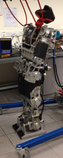
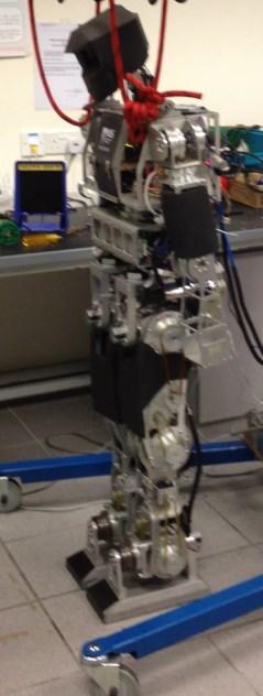
31 CHAPTER 3 ASLAN Hardware Specifications 3.1 Background The humanoid robot NUSBIP-III ASLAN is a successor of multiple legged robot platforms, namely the ROPE series, designed by the Legged Locomotion Group (LLG) at National University of Singapore. The 3D model of this robot and its CAD drawing is shown in Figure 10. Previous robots were kid-size robots, limited in a) 3D Model of ASLAN b) CAD drawing of ASLAN Figure 10. Models of humanoid robot ASLAN 18
![height and weight. However, NUSBIP-III is a human-sized robot which was developed around 2008, primarily to study bipedal walking [34,35].](/docs-images/94/120548902/images/32-0.jpg "Till now, the robot has demonstrated successful walking on even terrain, slope and stairs [36]. The robot also participated in ROBOCUP humanoid adult size category in 2010 and won first prize. 3.")
32 height and weight. However, NUSBIP-III is a human-sized robot which was developed around 2008, primarily to study bipedal walking [34,35]. Till now, the robot has demonstrated successful walking on even terrain, slope and stairs [36]. The robot also participated in ROBOCUP humanoid adult size category in 2010 and won first prize. 3.2 Mechanics ASLAN is a complete humanoid robot with a head, trunk, arms and legs. Lower limbs are equipped with six degrees of freedom (DOF) each. For each leg, three joints exist at the hip, one at knee and two at the ankle. While for the arms, three DOF exist at the shoulder and one at the elbow. Head of the robot is equipped with a single camera based vision system, where the neck allows pitch and yaw movement. The trunk is designed to carry the bulky electronics, sensors and batteries. The waist has a single DOF enabling swinging motion of the upper body through yaw movement. Figure 11. ASLAN flat foot design [37] 19
33 The robot ASLAN is a flat footed robot, illustrated in Figure 11. The foot design consists of an aluminum plate consistent of force/torque sensor to detect force value at impact. The foot is also equipped with rubber padding for impact absorption which is easily replaceable, thus facilitates maintenance Dimensions The research regarding balancing is restricted to sagittal plane, thus parameters for the humanoid are extracted for this particular plane only. Detailed parameter estimation is carried out using adaptive control, which will be explained in chapter 4, but nonetheless, a rough estimate of dimensions is required in order to achieve convergence within a specified range. Thus the basic inertial dimensions are calculated from the CAD drawings of the robot, where the parameters are tabulated as follows. The values shown below do not include weight added by the motors and electronics. Table 1. Dimensions of the robot ASLAN Body Length / mm Mass /Kg Foot x 2 Shank x 2 Thigh x 2 Upper Body
34 -60 o < Ankle Pitch<42 o -130 o <Knee Pitch <10 o -25 o <Hip Pitch<135 o Figure 12. Workspace descriptions for ankle, knee and hip pitch joints 21
35 3.2.2 Actuators All joints are connected to the motors through either harmonic drive or a combination with belt driven system. The aim is to provide higher torque and accuracy with zero backslash. However, this combination adds rigidity and high friction components to the system, which will be catered, to some extent, through parameter estimation. Table 2. Motion and motor specifications for lower body of ASLAN Joint Range of motion/deg Motor Power/watt Gear Ratio Hip Pitch -45 to Brushless motor 160:1 Knee Pitch -130 to Brushless motor 160:1 Ankle Pitch -45 to Brush motor 120:1 The allowed workspace configurations have been shown in Figure 12 for each joint. The maximum current rating for the motors has been given in Table 2. A 200 Watt Maxon motor has been used at the hip pitch joint which can provide up to 9 amperes of continuous current. Knee and ankle pitch motors have a comparatively lower power rating of 150 Watt, which can regulate 6 amperes of continuous current. 3.3 Electronics ASLAN consists of a single onboard computer, PC/104, which communicates with the motors through ELMO Whistle amplifiers, via a CAN BUS board, shown in Figure 13 and 14 respectively. ELMO is locally tuned to execute accurate position 22


36 control. However, the work described in this thesis operates the motors in current mode, which is implemented without any auto-tuning within ELMO. Figure 13. ASLAN electronics [37] Figure 14. Elmo whistle amplifier, used for controlling motors in ASLAN [37] 23


37 3.4 Sensors The robot has various sensors, illustrated in Figure 15, to measure orientation of the system and individual links. MAE3 Absolute encoders are mounted on the robot which can provide absolute position of a joint, essential for keeping track of posture and re-initialization. Encoders mounted at the shaft of the motor are used for more accurate position tracking purposes. With the exception of yaw joint at the hip, all other DOF in the lower body are equipped with this sensor. Due to mounting challenges, the hip yaw joint has a wire sensor encoder. An inertial measurement unit is developed by employing accelerometer and gyroscopes at the trunk of the robot. The sensors are connected to the PC through a DAQ board which converts analog signals from the sensors to digital form. MAE3 Encoder Wire Sensor Encoder Accelerometer Force\Torque Sensor Figure 15. Sensors on ASLAN [37] 24
38 Subsequent kalman filtering on extracted data results in an accurate estimate of the orientation of the robot. 3.5 Software The robot is controlled through the real time extension (RTX) software in Windows. RTX is a package which enables real time computation in Windows, with a sampling time of 10ms. However, the version of RTX used cannot communicate with ELMO driver. Thus a shared memory is created which serves to communicate between ELMO and main program running under RTX. All coding has been carried out in C++. Control strategies are implemented in the main program, updating relevant information in the shared memory, at every sampling time, which in turn updates the execution at the ELMO program. This communication loop ensures real time implementation of controllers on the robot. 3.6 Summary The humanoid robot ASLAN, introduced in this chapter, is used for evaluation and testing of the designed control strategy for push recovery. The robot will be controlled in a current mode, assuming a linear relationship between torque and current. The workspace and actuation limitations of the system play an important role in identification of optimal methodology to sustain balance. 25
39 Chapter 4 Acrobot Modeling - Adaptive Parameter Estimation The approach adopted in this work aims to maximize dependence on hip joint and subsequent upper body movements to sustain balance. The idea stems from the tiptoe maneuver in a human, commonly employed in uneven terrain situations. Mechanical design for humanoid foot has not yet advanced to a level where a compliant foot may be designed, which has the capacity to balance on the tip of the toes like humans. Nonetheless, the approach provides a means of deriving a control strategy that has lower torque requirements from the ankle joint, and can pave way for such a possibility to inculcate robustness and greater efficiency in humanoid robots. Thus, the following section describes modeling of the bipedal robot, ASLAN, as an acrobot, which is a double inverted pendulum with a passive ankle joint. 4.1 The Acrobot Model The acrobot is a commonly used two bar linkage system, which is stabilized vertically upwards. Despite having two degree of freedoms, one of the joints at the base is unactuated while the other is actuated. This system is extensively studied to solve the stabilization problem using various techniques. The humanoid robot in its sagittal plane is modeled as this two link acrobot, where the lower and upper body forms link one and two respectively. Using the lagrangian 26
40 system of equations to express the model of the bipedal robot as an acrobot, as shown in Figure 16, yields the following equations [38], y m 2 l 2 l C2 m 1 l 1 g l C1 x Figure 16. Humanoid robot modeled as acrobot (1) (2) where, ( ( )) ( ( )) ( ) ( ) ( ) ( ) ( ) ( ) ( ) 27
41 where q is the 2 1 vector of joint displacements, τ is the 2 1 vector of applied torques, D(q) is the 2 2 positive definite inertia matrix. C is the 2 1 vector of centripetal and coriolis torques, G(q) is the 2 1 vector of gravitational torques and F is the 2 1 vector of frictional torques induced by the gears and bearings in the robot. The friction model used is of the form, ( ) ( ) where and represent coulomb and viscous friction parameters [39], respectively. The primary reason for using this friction model is that can be estimated using simple trajectory and velocity profiles. This is particularly advantageous since the motors and gears are assembled with the humanoid links and individual identification through complicated procedures is not possible. The sgn( ) function is defined as, ( ) { (4) Based on these equations, the upper and lower body dynamics of the humanoid robot are coupled. However, friction components extant as part of the lagrangian equation of upper link, reflect friction at the hip joint only, while those in the lower links represent friction at the ankle joints. Since all other degrees of freedom in the sagittal plane, including knee joints and upper body limb joints, remain rigid, their friction components are ignored by the model. This model also assumes that both legs move together at all times, therefore are modeled as a single link. 28
42 4.1.1 Friction Approximation with Bipolar Sigmoid Function The friction model employed for parameter estimation was defined as, ( ) If this model is linearized, the coulomb friction component will reduce to zero. Thus the ( ) function is replaced by a bipolar sigmoid function which behaves almost exactly like the ( ) function. This bipolar sigmoid function is defined by the following equation, ( ) ( ) (5) Equivalence of these two models for a range of has been verified in Matlab. Figure 17. Response of bipolar sigmoid function 29
43 The use of bipolar sigmoid term provides a continuous function, simplifying differentiation for linearization of non-linear model for control design, unlike sgn( ) function. The graph in Figure 17 shows the response of the bipolar sigmoid function, in the range assigned, proving that this function behaves like the one described previously. Derivation of this function with respect to velocity of the respective joint yields the following function, ( ) ( ) ( ) ( ) ( ) Which can be further simplified to take a form as follows, ( ) ( ( ) ) ( ) It can be seen from the equation above, that this function does not go to zero as the velocity of the system goes to zero at the equilibrium point. Thus the following model is used to define the friction model, ( ) 30
44 4.2 Parameter Estimation The Concept Parameter estimation is an essential prerequisite to control of a bipedal robot which involves a comprehensive knowledge of the kinematic and dynamic features of individual links and actuators. Ideally, these should be identified before the assembly of these parts in order to maintain accuracy [40-41]. In many cases, inertial parameters including mass of links, center of mass locations, moment of inertia etc. are calculated from CAD drawings of the robot. Nonetheless, these drawings do not cater the added electronics and actuation system which contribute to added friction, inertia and total mass of the robot, essentially changing all the parameters previously determined. Thus the concept of parameter estimation takes its place, analyzing input-output behavior of the robot in order to estimate the relation between the two. Least square estimation is one of the most common and thoroughly researched strategies in literature which aims to minimize the difference between the actual output and estimated output from the model, over a series of predefined trajectories [39,42]. The standard model of the system is defined in terms of Langrangian equations, converted to a linear parametric form, defining the input output relation as, ( ) (9) Generally, torque is the input while joint position trajectory is the output. ( ) is the regressor matrix which is responsible for defining variables that govern the relation between input and output. 31
45 There are two major aspects that define the feasibility and success of this concept in practice. First is the identification of suitable trajectories which have the capacity to excite the dynamics of the entire robot [43]. Researchers have aimed to solve this issue by employing fourier series and calculating their respective coefficients through optimization strategies, under the constraints imposed by workspace boundaries of the links in terms of position, velocity and acceleration [44]. Those who found this tedious have attempted adding higher order polynomials to fourier series, where the coefficients are found during parameter estimation [45]. Nonetheless, whether these identified trajectories are aptly exciting for the given system is only determined after a series of experimental results. If the inertial parameters turn out to be negative in number, it is suggested that the trajectory was unable to excite the system, thus moving the entire procedure back to square one. Second hurdle is obtaining appropriate and noise free sensor readings. In some cases, force-torque measurements are obtained by torque sensors installed at every joint of the robot, which makes estimation relatively simpler. Otherwise, torque to a joint needs to be estimated through current, assuming a linear relationship as follows, (10) where N is the gear ratio and is the torque constant, obtained from the motor datasheet. Since the humanoid robot NUSBIP-III ASLAN is not equipped with torque sensors, this particular relationship is used to desired current. The Elmo motion controller which commands current to the motors is used to keep track of current readings at every instant. It is to be noted that this linear relationship holds true as long as the system remains in a close vicinity to the equilibrium position of the 32
46 system, described in chapter 5 as the stabilized state for the robot. Experimentations detailed in the proceeding sections verify that slight variations due to this assumption does not affect the overall performance of the system to a great extent. Literature reports that these torque constants vary up to 25% from their reported values during loading, thus adding another uncertainty to the system [43]. Also, the quantization error in position readings from the encoders, affects the velocity and acceleration, due to calculation by numerical differentiation. The resulting inaccuracy has a significant effect on the estimation procedure since the methodology originally relies heavily on accuracy of input and output readings. Weighted least squares method is a proposed modification to the least squares where the covariance of noise is assumed to be known and is added to the estimation procedure, to cater the noise in sensor readings [46]. Even though this method performs much better than its predecessor, the accuracy of estimated parameters is still questionable. Alternative approaches include Newton-Euler method and energy based model where the former requires force-torque sensor measurements while the latter requires only position and velocity variables, without the need of noise ridden acceleration readings [47-50]. However, the energy based model relies on the integration of torques and joint velocities to determine energy which adds an unknown bias to the readings Estimation of Simplified Bipedal Model Parameters In light of the previous methods presented for parameter estimation, it is extremely difficult to implement these on an assembled bipedal robot. Underactuation of the 33
47 robot makes it effectively unstable for a random trajectory. Appropriate trajectories which have the excitation capacity and cater all links of the bipedal robot are extremely difficult to design and depend on manual tuning which becomes a task on its own. For our bipedal robot ASLAN, inertial properties of individual links are obtained from CAD. However, control objectives require the bipedal robot to be modeled as a double inverted pendulum with a passive ankle, essentially as an acrobot. This aggregates the two legs as one link while leaving the feet out, since the ankles are passive. Similarly, the torso, trunk, head and arms are combined to form the second, upper link. Thus adaptive algorithm is used for parameter estimation of the simplified model. + + Non-linear Controller ROBOT q λ KPλ Adaptation Scheme + - e + - Figure 18. Control architecture for adaptive algorithm 34
48 Adaptive algorithm is a comprehensively researched concept which aims at minimizing the error between predicted and actual parameters of the system. This method provides a strategy which is sensitive to un-modeled dynamics and attempts to cater these by keeping track of the difference between desired and actual trajectories, updating parameters to minimize the resultant error. The version of the algorithm used in this thesis was presented by Slotine and Li [51], with their introduction of a sliding variable to the original concept of a passivity based controller. Passivity based controllers originate from the idea of shifting the energy minimum of the system from, ( ) ( )» ( ) ( ) thus ensuring that the potential energy and the kinetic energy of the system goes to zero [52]. The overall structure of this technique is shown in Figure 18. A sliding variable which ensures global and asymptotic stability of the system, is defined as, (11) (12) (13) which implies that if, then as. The new reference trajectory is defined as, (14) (15) (16) 35
49 In the equations above, q r refers to new reference trajectory while q d represents desired trajectory. The general equation of motion for the acrobot model is given as, ( ) ( ) ( ) ( ) (17) The update of parameters requires this equation to be rewritten in a parametric form where the respective matrices are defined as, ( ( )) ( ( )) ( ) [ ] (18) ( ( )) ( ) [ ( ) ( ) ] (19) ( ) ( ) * ( ) ( ) ( ) + (20) ( ) [ ( ) ( ) ] (21) The parameters in the above matrices are as follows, ( ) (22) 36
50 where m represents equivalent mass, l represents total length, l i represents the length of link i between adjacent joints, l ci defines distance between CoM of link i to the base of the respective joint, g represents acceleration due to gravity while f c and f v represent coulomb and viscous friction terms. The resultant update law is given by, ( ) (23) ( ) (24) where ( ) is the regressor matrix which represents model parameters in linear form and is a function of and. determines the updated parameter values and represents a constant positive definite matrix which is manually tuned to specify the rate of update for parameters. The adaptation law guarantees convergence of tracking errors [51]. However, it is essential to have a rough estimate of the dynamic parameters of the model so that the tuned parameters are only updated within a certain range. 4.3 Implementation For parameter estimation, ASLAN has been trained by introducing simple sinusoidal trajectories with varying amplitude and frequencies. These trajectories serve as reference to be followed, while tuning parameters of the non-linear model. The final values obtained at the end of this experiment have been tabulated in Table 3. 37
51 Table3. Final parameters and gain values PARAMETER ESTIMATED PARAMETER ESTIMATED Here the parameters make up the diagonal elements of the matrix, while all non-diagonal elements are zero. Figure19. Results for tracking reference trajectory after tuning parameters through Adaptive Control 38
52 Results for sinusoidal trajectories with amplitudes of 3 and 6 degrees with an associated frequency of 0.5 and 0.7 Hz respectively, have been shown in figure 19. The graph reflects the accuracy of the final values of these parameters, which are used in the next section to design a non-linear controller for humanoid stabilization. This process allows estimation of parameters without going through the trouble of designing complex trajectories. Also the rate of convergence may be increased by varying the gain K P and λ. a) P 6 convergence through adaptive tuning b) b) P 7 convergence through adaptive tuning 39
53 c) P 8 convergence through adaptive tuning d) P 9 convergence through adaptive tuning Figure20. Results for parameter convergence through Adaptive Control The figures above show how convergence is achieved for friction model parameters, P 6 P 9 respectively, where initial values were chosen to be zero. For parameters P 1 P 5, initial values were extracted from CAD drawings, which showed slight variation, of three significant figures, after adaptive tuning. Thus the final values were kept unchanged for these parameters. The complete non-linear model takes the following form, 40
54 ( ) (25) where ( ) is a 2 x 9 matrix and its coefficients are defined as, ( ) ( ( ) ( ) ( ) ( ) ) ( ) ( ) ( ) ( ) ( ) ( ) ( ) ( ) Thus the final extracted model is defined in parametric terms, which represents inertial properties of the complete humanoid robot in an aggregated form. 41
55 4.4 Summary This chapter introduces the acrobot model to represent the simplified dynamics of the complete humanoid robot. Adaptive algorithm was used to estimate parameters for this simplified model. The aim was to extract a non-linear system which captures the dynamics of the complex humanoid structure, in a sagittal plane only. This model will facilitate in formulation of the balancing control strategy, as described in chapter 5. 42
56 Chapter 5 Linear Control Design In order to resolve the problem of stabilization, linear state feedback is the simplest control approach which may be employed. This controller is designed based on linearization of the non-linear model extracted in chapter 4. For this purpose, the nonlinear equations of the system are linearized around q * 1D, q * 2D, which represents the desired position for the system for stabilization. The state x for linearization is defined as,, (26) (27) Where q 1 and q 2 represent angular rotations for ankle and hip respectively, while and represent respective angular velocities. The process of linearization is determined by employing Taylor series expansion, evaluated around the equilibrium point, as follows, ( ) ( ) * + ( ) * + ( ) (28) This expansion evaluates the differential of the non-linear function, with respect to the state variable x and control input u. the resultant state space model is determined by, 43
57 (29) Such that matrices A and B are defined as follows: * + * + (30) The matrix A encapsulates the dynamical properties of the system that exist due to the particular chosen state, while B determines the effect an input will have on the respective states. The idea of linearization around the equilibrium state represents a simplified model which is only valid within a close vicinity to this point. Thus the underlying assumption for this control technique implies instability for large deviations from the desired position. 5.1 Linearization of Non-Linear Model The complete non-linear model extracted from parameter estimation in the previous section consists of dynamic parameters of the model, in terms of inertial properties, friction parameters and controller gains. The reason behind using the complete nonlinear model for linearization is an attempt to have representation of all properties that play a role in determining the dynamics of the actual system. Linearization involves evaluation of the nonlinear function at the equilibrium point, which simplifies and decouples the system for control purposes. The non-linear model, to be linearized, is given in its parametric form in Equation 25, which can be rewritten such that the components of the equation are divided into inertial, 44
58 gravitational, coriolis and frictional components (from chapter 4). The properties are represented by the matrices H, G, C, F and K respectively. [ ] (31) Where the matrices can be written as follows, ( ( )) ( ( )) [ ] ( ( )) [ ( ) ( ) ] ( ) * ( ) ( ) ( ) + [ ( ) ( ) ] Linearization of this non-linear model is carried out by differentiation of individual matrices with respect to the state x and control input u which is torque commanded to the actuators represented by τ. The final linearized equation is defined by the following equation: [ ] [ ] * + * + (32) 45
59 where the matrix B is evaluation of the differential of function with respect to τ and is given as, * + while the differential of other matrices with respect to the state x are given as, [ ( ) ( ) ( ) ( ) ( ) ] [ ( ) ( ) ( ) ( ) ] [ ( ( ) ) ( ( ) ) ] The matrices, and evaluated at the equilibrium point x = [1.57, 0, 0, 0] are defined as, [ ] * + 46
60 [ ] [ ( ) ( ) ] ( ) After linearization, it can be seen that coriolis and centrifugal terms extant in the original equations have been eliminated and do not contribute to the simplified model. However, all other dynamic properties of the original system represent themselves in the linearized form, retaining essence of the true dynamics to a certain extent. Having defined the state space model, it is important to determine appropriate control input which will guarantee stability and convergence of the system to the desired position. For this purpose, state feedback is employed which requires gain tuning to get convergence at the desired rate, under constraints imposed by actuator and joint limitations. Optimality in this situation is determined by employing the linear quadratic regulator, described in the next section. 5.2 Linear Quadratic Regulator-The Theory In order to determine the optimal trajectory, after the push, towards the vertical desired position, an optimal feedback controller needs to be designed. Optimality [4] has been defined in terms of a quadratic cost function as follows, ( ) (33) 47
61 The linear feedback matrix u is defined as, (34) The L matrix is responsible for defining optimality in the linear quadratic regulator. This matrix is obtained by solving the riccati equation which is given as follows, (35) The gain matrix is determined by, (36) By varying the gain matrices Q and R, the penalty on error of the state x and the control effort u is controlled. The gain matrices used in experimentation are, [ ] where a higher penalty is placed on the control effort as compared to the state. These gains are determined by keeping in mind joint motor limitations for providing the control effort in terms of torque. This approach is much faster as compared to traditional pole placement techniques, while the desired balance of priorities between the state and control effort can be regulated much easily. 48
62 5.3 Simulation Results in MATLAB The resultant state space model, derived in the section above, is tested under disturbance applied to the system. Controller gains for the resultant feedback controller are as follows, Figure 21 shows convergence has been achieved within an approximate duration of 4 seconds, but the control effort employed goes up to - 10 amperes, which is quite out of reach for the actuators. If the R gain value is increased, to employ lower control effort, stabilization is achieved after a few oscillations, as shown in Figure 22. Ө 2 Ө 1 Figure 21. Simulation results for x0 = [0.02;0.03;0;0] 49
63 Ө 1 Ө 2 Figure 22. Simulation results x0 = [0.02;0.03;0;0] with higher R value Ө 2 Ө 1 Figure 23. Simulation results x0 = [0;0.01;0;0] for upper body disturbance only 50
64 Ө 2 Ө 1 Figure 24. Simulation results x0 = [0.01;0;0;0] for lower body disturbance only Figures 23 and 24 show that if only a disturbance in the hip joint is induced, the desired current remains within range. However, desired control effort goes out of range if only ankle joint disturbance is induced. Since the humanoid is modeled as an acrobot, it is inevitable to push the robot in a way which causes only hip joint instability. Thus this approach is not suitable when passive ankle joint stabilization is required. 5.4 Summary The results show that the current required to stabilize the system without oscillation is greater than the DC motor limit at the hip. Experimentation also shows that a push 51
65 causing disturbance in the upper body only did not require current that was out of range for the motors, which is essentially not possible since any disturbance to the system would affect both ankle and hip joints. Also, a slight disturbance in the ankle joint immediately requires greater control effort for stabilization. 52
66 Chapter 6 Partial Feedback Linearization In the last chapter a linear feedback controller was designed using LQR. The drawback of employing this technique is requirement of higher control effort than the actuator limitation. This problem is evident during stabilization of the passive ankle joint. Therefore, a non-linear control approach is adopted with the aim of stabilizing the ankle, employing control effort within actuators limits. 6.1 Partial Feedback Linearization- the Theory Since the bipedal robot has been modeled as an under-actuated system, with passive ankle and active hip joints, it is essential to comprehend that such systems are not completely feedback linearizable. This section of the thesis introduces Partial Feedback Linearization control which is based on linearizing the actuated degree of freedom, by introducing non-linear feedback in the control loop. This methodology is quite common when it comes to the control of autonomous manipulators, but is not generally approached for bipedal robots. A huge contributing factor is the ignorance of the true non-linearities of the complete system, which is difficult to articulate independently for each limb. Hence, parameter estimation through adaptive control remains of vital importance to the implementation of this controller. 53
67 The objective of a partial feedback linearization controller is to employ the nonlinear model as feedback to be able to nullify the non linearities and create a resultant linear system to control. This approach has been implemented by Spong [50], in two ways, namely Collocated and Non Collocated linearization. Collocated, as the name suggests, is a control strategy to control the actuated link in an acrobot, essentially the upper body. Non-Collocated linearization provides the capacity to control the passive or un-actuated link in the system, which in our case is the ankle joint of the humanoid robot. Since the objective of employing non-linear feedback is to stabilize the ankle, Non-Collocated Partial Feedback Linearization (NCPFL) is employed. Proceeding sections of this chapter highlight the technicalities behind implementation of this control technique. 6.2 Non-Collocated Partial Feedback Linearization (NCPFL) In contradiction to Collocated linearization, Non-Collocated partial feedback linearization involves the direct control of the passive joint, employing upper body movements through hip joint actuation. This control strategy may be implemented given the condition defined by Strong-Inertial Coupling [38]. This condition imposes restrictions on the inertia matrix of the system stating, ( ( )) (37) where n is the total number of degrees of freedom, m refers to the actuated number of degrees of freedom, d 12 is the coefficient described in equation 1. This condition 54
68 requires that the number of active degrees of freedom should be greater or equal to the number of passive joints in the system. Since this condition is satisfied by the chosen acrobot model, the nonlinear feedback controller is designed such that the output to be controlled is the angle of the ankle joint, reducing its dynamics to a second order linear system, (38) Considering the following equations of motion derived from equation 1 and 2, yields the following non-linear model, (39) (40) Manipulation of Equation 39 with an assumption of no ankle torque leads to, ( ) (41) Substituting Equation 41 in Equation 40 yields the following expression, (42) Such that 55
69 These terms expressed in parametric form extracted from chapter 4 yields the following expressions respectively, ( ( )) ( ) ( ( )) ( ( ) ( ) ) ( ( )) ( ) ( ( ) ( )) ( ( )) ( ) ( ( )) ( ( )) ( ) Since the objective is to restore q 1 to its equilibrium state of q * 1 = 90 o, which represents a vertical configuration for the lower body, the following additional control input is added, (43) which is replaced by local PD control terms as follows, ( ) (44) 56
70 This input effectively reduces the dynamics of the lower link to a second order linear system. Local stability properties of this controller are explained and verified in [50]. 6.3 Simulation Results in MATLAB The performance of this controller has been tested in MATLAB. The gain values used for NCPFL are K vd = -30, and K vp = -5, which are manually tuned values. Employing these gains, the response of this system, to an initial disturbance of approximately 1.2 degrees to the ankle and 1.7 degrees to the hip, responds in the manner shown in Figure 25. The graph below shows convergence has been achieved with an approximate duration of 4 seconds, but the control effort employed goes up to -6 amperes, which is within the prescribed limits for the actuators. Ө 1 Ө 2 Figure 25. Simulation results x0 = [-0.02;0.03;0;0] using NCPFL and LQR 57
71 Ө 2 Ө 1 Figure 26. Simulation results x0 = [0.02;0;0;0] using NCPFL Figure 26 is another example of the response of NCPFL to a disturbance of 1.2 degrees in the lower body only, which results in a control effort requirement of up to - 3amperes. 6.4 Summary Experimentation shows that this control approach is apt for passive ankle stabilization. In order to achieve quick convergence for the hip joint, the linear feedback approach introduced in chapter 5, is integrated with NCPFL, only when the system is in a close vicinity to the equilibrium state. Details of implementation of this integrated approach have been described in the next chapter, followed by simulation verification in Webots and hardware experimentation. 58
72 Chapter 7 Full Body Control Architecture Upon application of a push, the robot rotates about its feet, as a rigid structure, due to high friction at the hip joint. In order to stabilize the system using a single actuated degree of freedom at the hip, design of a non-linear control strategy for the derived model is explored. The controller described aims to stabilize the ankle of the biped as a first priority, which inturn leads to convergence of the hip joint near the desired state. However, during practical implementation, NCPFL may lead to oscillations of upper body before complete stabilization, due to which the system switches to a linear feedback controller, which swiftly stabilizes the humanoid. Based on these objectives, the design of a synergy of linear and non-linear control strategy for the derived model has been explored. It has been seen from experimentation results in the previous chapters that a standalone linear state feedback controller was not able to cater lower body disturbance. Thus a non-linear approach has been adopted which caters this objective. The controller synergy is described in detail in the following section. 7.1 Full Body Control A control hierarchy shown in Figure 27, has been designed to implement push recovery in real time. At every sampling time, the state x, including angular rotations 59
73 ( ) + - LQR Feedback *ϒ = 1 Priority Regulation ROBOT Non-Collocated Feedback ( ) *ϒ = 0 Ankle PD Control Figure 27. Full body control architecture and velocities for ankle and hip, is estimated through motor encoders and IMU readings. Locations of CoM A and CoM H (horizontal projections of ankle and hip joint angular displacements) of the chosen model determine which controller should be given priority over the other. Since upon application of push, CoM A and CoM H both are disturbed, the non-linear approach is employed. Once the lower body has converged to the desired state, while upper body is in close vicinity, linear feedback kicks in. Based on the boundary conditions defined below, a variable is introduced such that the value of is determined by, * (45) { (46) The final torque value commanded to the motor is given by the following, 60
74 ( ) (47) The control strategy formulated defines desired torque for the hip joint. This is accompanied with a simple PD controller at the ankle which is given as, ( ) (48) This ankle torque is employed to cater the friction components at the ankle joint. Since the assumption of ankle joint being passive cannot be achieved in a harmonic drive driven joint of the humanoid robot ASLAN, a small amount of torque is employed which assists in overcoming friction at the ankle joint to achieve desired control. It will be shown in experimental evaluation that desired ankle torque is greatly reduced with respect to available saturation levels of the actuator. Also, the effects of using the proposed controller as a standalone strategy, with effectively zero ankle torque, will be discussed in the preceding sections. 7.2 Implementation on WEBOTS Simulation Setup Detailed testing of the proposed strategy has been carried out in the Webots simulator [53]. The humanoid model of a humanoid robot shown in Figure 28, has been designed in this environment with a total length of 1.7m and weight of 86.6Kg. Each limb of the humanoid consists of six degrees of freedom. The robot consists of 3-axis 61

75 global positioning sensor (GPS) and 3-axis accelerometer for position and orientation sensing. The simulation and controller output is updated at a frequency of 125Hz. The humanoid robot initially stands straight on an even terrain, and is eventually pushed to add disturbance to the stable system. The robot is pushed using an autonomous ball robot model which has a mobile base. This ball is equipped with a force sensor which measures the impulse at impact with the humanoid. Figure 28. Humanoid Simulation Model in Webots The height of the ball is at 1.2m such that the humanoid robot is pushed in the middle of the torso. The ball does not apply a continuous push, but rather provides an impulse at the instant of collision. After impact, the robot driving the ball moves in an opposing direction and does not come into contact with the robot. 62
76 7.2.2 Implementation Details The servos of the robot are operated in torque control mode, where the commanded torque is determined by equation 10. The gain values used for NCPFL are K vd = -30, and K vp = -5. The LQR controller is tuned in MATLAB where the values for Q and R matrices for state space model are given as Q = I(4x4) and R = 10e -12. The optimized L matrix extracted is defined as L= [30.15, 147.4, ]. In this case, no PD controller is required at the ankle because Webots allows the servo motor to be operated in a torque mode which does not add any friction at the ankle joint. With the parameters defined above, the simulation is tested under impulse of varying magnitude, imparted to the humanoid from both front and back, restricted to sagittal plane only. The variation in magnitude of this force is achieved by increasing the initial distance between the ball and the humanoid robot. The ball is controlled using an autonomous mobile base which moves in the direction towards the robot. At impact with the robot, detected by the force sensor in the ball, the direction of the base is reversed, creating an effect of a ball hitting the robot and bouncing back. An extra GPS is added at the location defined by CoM AVG which is given as, (49) This enables determination of CoM AVG linear position and velocity. This term is primarily determined to extract phase plots for various trajectories and determine stable and unstable areas for the system. 63


77 7.3 Result Evaluation Figure 29 shows the response of the humanoid robot under an instantaneous disturbance of 164Ns from the back. The graphs shown in Figure 30 reflect the ability of the controller to cater disturbances of such large magnitude. The graph also shows dependence of less than 10Nm on ankle torque while the saturation limits go much beyond this value. Figure 31 shows a similar response to 130Nm impulse imparted to the humanoid from the front while Figure 32 shows the resultant variation in angular rotation, CoM of each link and current employed by the actuators. FP Figure 29. Simulation results for a forward push 64
78 a) Angular Deflection b) Applied Torque c) CoM A and CoM H Deflection Figure 30. Response of the humanoid robot to the applied push 65

79 BP Figure 31. Response of the humanoid robot to the applied backward push 66
80 a) Angular Deflection b) Applied Torque c) CoM A and CoM H Deflection Figure 32. Response of the humanoid robot to the applied push 67

81 The phase plot shows the stability margin for CoM AVG of the simulated robot for multiple trajectories with varying magnitude of force applied. The stable and unstable regions have been achieved by experimentation on the simulator, for multiple trajectories with varying magnitudes of force applied. The shaded area in this figure corresponds to the unstable region. The trajectory plot in the figure below shows that disturbances causing an instantaneous CoM AVG velocity shift beyond 0.45ms -1, leads to an unstable trajectory. Such levels of disturbance should be catered by taking a step, which is beyond the scope of this work. Figure 33. Phase plot for multiple trajectories of CoM AVG 68
82 a) Phase Plot for (Ɵ ) and Ɵ 1dot b) Phase Plot for Ɵ 2 and Ɵ 2dot Figure 34. Phase plots for state x for multiple trajectories 69
83 The phase plots shown in Figures 34 reflect the stabilization of the controlled states of the system, which converge at respective equilibrium states for multiple trajectories. These graphs also depict the common range of variation induced by the disturbance, that the controller is capable of handling. 7.4 Experimental Evaluation on NUSBIP-III ASLAN Hardware Platform The robot NUSBIP-III ASLAN at NUS is used for implementation of the controller designed above. ASLAN is a human sized humanoid robot equipped with DC servo motors which are controlled through ELMO amplifier. PC/104 is the major processing unit with a processing frequency of 100Hz, which communicates with ELMO through CAN BUS. The robot is equipped with accelerometer and gyroscope to provide inertial measurement. Rotational measurements are sensed through encoders mounted at the motors Implementation Details The servos of the robot are operated in current mode, where the commanded current is determined as follows, 70
84 where K T and N represent torque constant specified in the motor datasheet, and gear ratio respectively. Since the total weight and size of the simulated and actual robots are different, gains for linear and non-linear controllers are recomputed. The gains used for the NCPFL are K vd = 45, and K vp = 5. The LQR values for Q and R matrices for state space model are given as Q = I(4x4) and R = 10e -12. The L matrix is defined as L = [10.15, , ]. The gains employed at the ankle for PD control are defined as K DA = 0.5, and K PA = Result Evaluation Figure 35 shows response to a push applied from front and back, while Figures 36 and 37 show how the angles, current and CoM of each link of the humanoid robot vary with respect to time. Graphs in Figure 38 shows response of the robot for multiple push imparted to the humanoid from front and back. It can be seen from Figure 38b that the maximum ankle current employed is -1.5<i A <1.5 amperes where the ankle motor has the capacity to provide up to 6 amperes of continuous current. Thus it is hypothesized that the current employed through PD controller assists to overcome ankle friction components during upper body movements determined by NCPFL. 71

 Back")


85 FP a) Front Push BP b) Back Push Figure 35. Response of humanoid robot ASLAN to a push from front and back 72
ROBOTICS ENG YOUSEF A. SHATNAWI INTRODUCTION
 ROBOTICS INTRODUCTION THIS COURSE IS TWO PARTS Mobile Robotics. Locomotion (analogous to manipulation) (Legged and wheeled robots). Navigation and obstacle avoidance algorithms. Robot Vision Sensors and
Optimal Control System Design
 Chapter 6 Optimal Control System Design 6.1 INTRODUCTION The active AFO consists of sensor unit, control system and an actuator. While designing the control system for an AFO, a trade-off between the transient
A Semi-Minimalistic Approach to Humanoid Design
 International Journal of Scientific and Research Publications, Volume 2, Issue 4, April 2012 1 A Semi-Minimalistic Approach to Humanoid Design Hari Krishnan R., Vallikannu A.L. Department of Electronics
Humanoids. Lecture Outline. RSS 2010 Lecture # 19 Una-May O Reilly. Definition and motivation. Locomotion. Why humanoids? What are humanoids?
 Humanoids RSS 2010 Lecture # 19 Una-May O Reilly Lecture Outline Definition and motivation Why humanoids? What are humanoids? Examples Locomotion RSS 2010 Humanoids Lecture 1 1 Why humanoids? Capek, Paris
Automatic Control Motion control Advanced control techniques
 Automatic Control Motion control Advanced control techniques (luca.bascetta@polimi.it) Politecnico di Milano Dipartimento di Elettronica, Informazione e Bioingegneria Motivations (I) 2 Besides the classical
Current sensing feedback for humanoid stability
 Rochester Institute of Technology RIT Scholar Works Theses Thesis/Dissertation Collections 7-1-2013 Current sensing feedback for humanoid stability Matthew DeCapua Follow this and additional works at:
DEVELOPMENT OF A HUMANOID ROBOT FOR EDUCATION AND OUTREACH. K. Kelly, D. B. MacManus, C. McGinn
 DEVELOPMENT OF A HUMANOID ROBOT FOR EDUCATION AND OUTREACH K. Kelly, D. B. MacManus, C. McGinn Department of Mechanical and Manufacturing Engineering, Trinity College, Dublin 2, Ireland. ABSTRACT Robots
sin( x m cos( The position of the mass point D is specified by a set of state variables, (θ roll, θ pitch, r) related to the Cartesian coordinates by:
 related to the Cartesian coordinates by:") Research Article International Journal of Current Engineering and Technology ISSN 77-46 3 INPRESSCO. All Rights Reserved. Available at http://inpressco.com/category/ijcet Modeling improvement of a Humanoid
Research Article International Journal of Current Engineering and Technology ISSN 77-46 3 INPRESSCO. All Rights Reserved. Available at http://inpressco.com/category/ijcet Modeling improvement of a Humanoid
Korea Humanoid Robot Projects
 Korea Humanoid Robot Projects Jun Ho Oh HUBO Lab., KAIST KOREA Humanoid Projects(~2001) A few humanoid robot projects were existed. Most researches were on dynamic and kinematic simulations for walking
DEVELOPMENT OF THE HUMANOID ROBOT HUBO-FX-1
 DEVELOPMENT OF THE HUMANOID ROBOT HUBO-FX-1 Jungho Lee, KAIST, Republic of Korea, jungho77@kaist.ac.kr Jung-Yup Kim, KAIST, Republic of Korea, kirk1@mclab3.kaist.ac.kr Ill-Woo Park, KAIST, Republic of
Robot Joint Angle Control Based on Self Resonance Cancellation Using Double Encoders
 Robot Joint Angle Control Based on Self Resonance Cancellation Using Double Encoders Akiyuki Hasegawa, Hiroshi Fujimoto and Taro Takahashi 2 Abstract Research on the control using a load-side encoder for
Chapter 1. Robot and Robotics PP
 Chapter 1 Robot and Robotics PP. 01-19 Modeling and Stability of Robotic Motions 2 1.1 Introduction A Czech writer, Karel Capek, had first time used word ROBOT in his fictional automata 1921 R.U.R (Rossum
Robo-Erectus Jr-2013 KidSize Team Description Paper.
 Robo-Erectus Jr-2013 KidSize Team Description Paper. Buck Sin Ng, Carlos A. Acosta Calderon and Changjiu Zhou. Advanced Robotics and Intelligent Control Centre, Singapore Polytechnic, 500 Dover Road, 139651,
The Tele-operation of the Humanoid Robot -Whole Body Operation for Humanoid Robots in Contact with Environment-
 The Tele-operation of the Humanoid Robot -Whole Body Operation for Humanoid Robots in Contact with Environment- Hitoshi Hasunuma, Kensuke Harada, and Hirohisa Hirukawa System Technology Development Center,
ROMEO Humanoid for Action and Communication. Rodolphe GELIN Aldebaran Robotics
 ROMEO Humanoid for Action and Communication Rodolphe GELIN Aldebaran Robotics 7 th workshop on Humanoid November Soccer 2012 Robots Osaka, November 2012 Overview French National Project labeled by Cluster
Shuffle Traveling of Humanoid Robots
 Shuffle Traveling of Humanoid Robots Masanao Koeda, Masayuki Ueno, and Takayuki Serizawa Abstract Recently, many researchers have been studying methods for the stepless slip motion of humanoid robots.
Kid-Size Humanoid Soccer Robot Design by TKU Team
 Kid-Size Humanoid Soccer Robot Design by TKU Team Ching-Chang Wong, Kai-Hsiang Huang, Yueh-Yang Hu, and Hsiang-Min Chan Department of Electrical Engineering, Tamkang University Tamsui, Taipei, Taiwan E-mail:
Team Description for Humanoid KidSize League of RoboCup Stephen McGill, Seung Joon Yi, Yida Zhang, Aditya Sreekumar, and Professor Dan Lee
 Team DARwIn Team Description for Humanoid KidSize League of RoboCup 2013 Stephen McGill, Seung Joon Yi, Yida Zhang, Aditya Sreekumar, and Professor Dan Lee GRASP Lab School of Engineering and Applied Science,
Active Vibration Isolation of an Unbalanced Machine Tool Spindle
 Active Vibration Isolation of an Unbalanced Machine Tool Spindle David. J. Hopkins, Paul Geraghty Lawrence Livermore National Laboratory 7000 East Ave, MS/L-792, Livermore, CA. 94550 Abstract Proper configurations
HUMANOID ROBOT SIMULATOR: A REALISTIC DYNAMICS APPROACH. José L. Lima, José C. Gonçalves, Paulo G. Costa, A. Paulo Moreira
 HUMANOID ROBOT SIMULATOR: A REALISTIC DYNAMICS APPROACH José L. Lima, José C. Gonçalves, Paulo G. Costa, A. Paulo Moreira Department of Electrical Engineering Faculty of Engineering of University of Porto
SELF-BALANCING MOBILE ROBOT TILTER
 Tomislav Tomašić Andrea Demetlika Prof. dr. sc. Mladen Crneković ISSN xxx-xxxx SELF-BALANCING MOBILE ROBOT TILTER Summary UDC 007.52, 62-523.8 In this project a remote controlled self-balancing mobile
Why Humanoid Robots?*
 Why Humanoid Robots?* AJLONTECH * Largely adapted from Carlos Balaguer s talk in IURS 06 Outline Motivation What is a Humanoid Anyway? History of Humanoid Robots Why Develop Humanoids? Challenges in Humanoids
Robo-Erectus Tr-2010 TeenSize Team Description Paper.
 Robo-Erectus Tr-2010 TeenSize Team Description Paper. Buck Sin Ng, Carlos A. Acosta Calderon, Nguyen The Loan, Guohua Yu, Chin Hock Tey, Pik Kong Yue and Changjiu Zhou. Advanced Robotics and Intelligent
Control Architecture and Algorithms of the Anthropomorphic Biped Robot Bip2000
 Control Architecture and Algorithms of the Anthropomorphic Biped Robot Bip2000 Christine Azevedo and the BIP team INRIA - 655 Avenue de l Europe 38330 Montbonnot, France ABSTRACT INRIA [1] and LMS [2]
UKEMI: Falling Motion Control to Minimize Damage to Biped Humanoid Robot
 Proceedings of the 2002 IEEE/RSJ Intl. Conference on Intelligent Robots and Systems EPFL, Lausanne, Switzerland October 2002 UKEMI: Falling Motion Control to Minimize Damage to Biped Humanoid Robot Kiyoshi
Development of a Humanoid Biped Walking Robot Platform KHR-1 - Initial Design and Its Performance Evaluation
 Development of a Humanoid Biped Walking Robot Platform KHR-1 - Initial Design and Its Performance Evaluation Jung-Hoon Kim, Seo-Wook Park, Ill-Woo Park, and Jun-Ho Oh Machine Control Laboratory, Department
4R and 5R Parallel Mechanism Mobile Robots
 4R and 5R Parallel Mechanism Mobile Robots Tasuku Yamawaki Department of Mechano-Micro Engineering Tokyo Institute of Technology 4259 Nagatsuta, Midoriku Yokohama, Kanagawa, Japan Email: d03yamawaki@pms.titech.ac.jp
Design and Implementation of a Simplified Humanoid Robot with 8 DOF
 Design and Implementation of a Simplified Humanoid Robot with 8 DOF Hari Krishnan R & Vallikannu A. L Department of Electronics and Communication Engineering, Hindustan Institute of Technology and Science,
A Passive System Approach to Increase the Energy Efficiency in Walk Movements Based in a Realistic Simulation Environment
 A Passive System Approach to Increase the Energy Efficiency in Walk Movements Based in a Realistic Simulation Environment José L. Lima, José A. Gonçalves, Paulo G. Costa and A. Paulo Moreira Abstract This
ZJUDancer Team Description Paper
 ZJUDancer Team Description Paper Tang Qing, Xiong Rong, Li Shen, Zhan Jianbo, and Feng Hao State Key Lab. of Industrial Technology, Zhejiang University, Hangzhou, China Abstract. This document describes
Team Description 2006 for Team RO-PE A
 Team Description 2006 for Team RO-PE A Chew Chee-Meng, Samuel Mui, Lim Tongli, Ma Chongyou, and Estella Ngan National University of Singapore, 119260 Singapore {mpeccm, g0500307, u0204894, u0406389, u0406316}@nus.edu.sg
Design and Experiments of Advanced Leg Module (HRP-2L) for Humanoid Robot (HRP-2) Development
 for Humanoid Robot (HRP-2) Development") Proceedings of the 2002 IEEE/RSJ Intl. Conference on Intelligent Robots and Systems EPFL, Lausanne, Switzerland October 2002 Design and Experiments of Advanced Leg Module (HRP-2L) for Humanoid Robot (HRP-2)
Proceedings of the 2002 IEEE/RSJ Intl. Conference on Intelligent Robots and Systems EPFL, Lausanne, Switzerland October 2002 Design and Experiments of Advanced Leg Module (HRP-2L) for Humanoid Robot (HRP-2)
Nao Devils Dortmund. Team Description for RoboCup Matthias Hofmann, Ingmar Schwarz, and Oliver Urbann
 Nao Devils Dortmund Team Description for RoboCup 2014 Matthias Hofmann, Ingmar Schwarz, and Oliver Urbann Robotics Research Institute Section Information Technology TU Dortmund University 44221 Dortmund,
Adaptive Dynamic Simulation Framework for Humanoid Robots
 Adaptive Dynamic Simulation Framework for Humanoid Robots Manokhatiphaisan S. and Maneewarn T. Abstract This research proposes the dynamic simulation system framework with a robot-in-the-loop concept.
Integration of Manipulation and Locomotion by a Humanoid Robot
 Integration of Manipulation and Locomotion by a Humanoid Robot Kensuke Harada, Shuuji Kajita, Hajime Saito, Fumio Kanehiro, and Hirohisa Hirukawa Humanoid Research Group, Intelligent Systems Institute
System Overview of The Humanoid Robot Blackmann
 stem Overview of The Humanoid Robot Blackmann JIAN WANG, TAO SHENG, JIANWEN WANG and HONGXU MA College of Mechtronic and Automation National University of Defense Technology Changsha, Hunan Province THE
Preliminary study of the vibration displacement measurement by using strain gauge
 Songklanakarin J. Sci. Technol. 32 (5), 453-459, Sep. - Oct. 2010 Original Article Preliminary study of the vibration displacement measurement by using strain gauge Siripong Eamchaimongkol* Department
Mechanical Design of Humanoid Robot Platform KHR-3 (KAIST Humanoid Robot - 3: HUBO) *
 *") Proceedings of 2005 5th IEEE-RAS International Conference on Humanoid Robots Mechanical Design of Humanoid Robot Platform KHR-3 (KAIST Humanoid Robot - 3: HUBO) * Ill-Woo Park, Jung-Yup Kim, Jungho Lee
Proceedings of 2005 5th IEEE-RAS International Conference on Humanoid Robots Mechanical Design of Humanoid Robot Platform KHR-3 (KAIST Humanoid Robot - 3: HUBO) * Ill-Woo Park, Jung-Yup Kim, Jungho Lee
Increasing the Impedance Range of a Haptic Display by Adding Electrical Damping
 Increasing the Impedance Range of a Haptic Display by Adding Electrical Damping Joshua S. Mehling * J. Edward Colgate Michael A. Peshkin (*)NASA Johnson Space Center, USA ( )Department of Mechanical Engineering,
Position Control of AC Servomotor Using Internal Model Control Strategy
 Position Control of AC Servomotor Using Internal Model Control Strategy Ahmed S. Abd El-hamid and Ahmed H. Eissa Corresponding Author email: Ahmednrc64@gmail.com Abstract: This paper focuses on the design
Chapter 1 Introduction
 Chapter 1 Introduction It is appropriate to begin the textbook on robotics with the definition of the industrial robot manipulator as given by the ISO 8373 standard. An industrial robot manipulator is
Active Stabilization of a Humanoid Robot for Real-Time Imitation of a Human Operator
 2012 12th IEEE-RAS International Conference on Humanoid Robots Nov.29-Dec.1, 2012. Business Innovation Center Osaka, Japan Active Stabilization of a Humanoid Robot for Real-Time Imitation of a Human Operator
Development and Evaluation of a Centaur Robot
 Development and Evaluation of a Centaur Robot 1 Satoshi Tsuda, 1 Kuniya Shinozaki, and 2 Ryohei Nakatsu 1 Kwansei Gakuin University, School of Science and Technology 2-1 Gakuen, Sanda, 669-1337 Japan {amy65823,
Servo Tuning Tutorial
 Servo Tuning Tutorial 1 Presentation Outline Introduction Servo system defined Why does a servo system need to be tuned Trajectory generator and velocity profiles The PID Filter Proportional gain Derivative
How to perform transfer path analysis
 Siemens PLM Software How to perform transfer path analysis How are transfer paths measured To create a TPA model the global system has to be divided into an active and a passive part, the former containing
Birth of An Intelligent Humanoid Robot in Singapore
 Birth of An Intelligent Humanoid Robot in Singapore Ming Xie Nanyang Technological University Singapore 639798 Email: mmxie@ntu.edu.sg Abstract. Since 1996, we have embarked into the journey of developing
On Observer-based Passive Robust Impedance Control of a Robot Manipulator
 Journal of Mechanics Engineering and Automation 7 (2017) 71-78 doi: 10.17265/2159-5275/2017.02.003 D DAVID PUBLISHING On Observer-based Passive Robust Impedance Control of a Robot Manipulator CAO Sheng,
Robotic Swing Drive as Exploit of Stiffness Control Implementation
 Robotic Swing Drive as Exploit of Stiffness Control Implementation Nathan J. Nipper, Johnny Godowski, A. Arroyo, E. Schwartz njnipper@ufl.edu, jgodows@admin.ufl.edu http://www.mil.ufl.edu/~swing Machine
EFFECT OF INERTIAL TAIL ON YAW RATE OF 45 GRAM LEGGED ROBOT *
 EFFECT OF INERTIAL TAIL ON YAW RATE OF 45 GRAM LEGGED ROBOT * N.J. KOHUT, D. W. HALDANE Department of Mechanical Engineering, University of California, Berkeley Berkeley, CA 94709, USA D. ZARROUK, R.S.
Ball Balancing on a Beam
 1 Ball Balancing on a Beam Muhammad Hasan Jafry, Haseeb Tariq, Abubakr Muhammad Department of Electrical Engineering, LUMS School of Science and Engineering, Pakistan Email: {14100105,14100040}@lums.edu.pk,
Active Stabilization of a Humanoid Robot for Impact Motions with Unknown Reaction Forces
 2012 IEEE/RSJ International Conference on Intelligent Robots and Systems October 7-12, 2012. Vilamoura, Algarve, Portugal Active Stabilization of a Humanoid Robot for Impact Motions with Unknown Reaction
DIGITAL SPINDLE DRIVE TECHNOLOGY ADVANCEMENTS AND PERFORMANCE IMPROVEMENTS
 DIGITAL SPINDLE DRIVE TECHNOLOGY ADVANCEMENTS AND PERFORMANCE IMPROVEMENTS Ty Safreno and James Mello Trust Automation Inc. 143 Suburban Rd Building 100 San Luis Obispo, CA 93401 INTRODUCTION Industry
Design and Implementation of Humanoid Biped Walking Robot Mechanism towards Natural Walking
 Proceedings of the 2011 IEEE International Conference on Robotics and Biomimetics December 7-11, 2011, Phuket, Thailand Design and Implementation of Humanoid Biped Walking Robot Mechanism towards Natural
FUmanoid Team Description Paper 2010
 FUmanoid Team Description Paper 2010 Bennet Fischer, Steffen Heinrich, Gretta Hohl, Felix Lange, Tobias Langner, Sebastian Mielke, Hamid Reza Moballegh, Stefan Otte, Raúl Rojas, Naja von Schmude, Daniel
Stabilize humanoid robot teleoperated by a RGB-D sensor
 Stabilize humanoid robot teleoperated by a RGB-D sensor Andrea Bisson, Andrea Busatto, Stefano Michieletto, and Emanuele Menegatti Intelligent Autonomous Systems Lab (IAS-Lab) Department of Information
Elements of Haptic Interfaces
 Elements of Haptic Interfaces Katherine J. Kuchenbecker Department of Mechanical Engineering and Applied Mechanics University of Pennsylvania kuchenbe@seas.upenn.edu Course Notes for MEAM 625, University
Concept and Architecture of a Centaur Robot
 Concept and Architecture of a Centaur Robot Satoshi Tsuda, Yohsuke Oda, Kuniya Shinozaki, and Ryohei Nakatsu Kwansei Gakuin University, School of Science and Technology 2-1 Gakuen, Sanda, 669-1337 Japan
Cost Oriented Humanoid Robots
 Cost Oriented Humanoid Robots P.Kopacek Vienna University of Technology, Intelligent Handling and Robotics- IHRT, Favoritenstrasse 9/E325A6; A-1040 Wien (Tel:++43 1 58801 31800, e-mail: kopacek@ihrt.tuwien.ac.at)
Humanoid robot. Honda's ASIMO, an example of a humanoid robot
 Humanoid robot Honda's ASIMO, an example of a humanoid robot A humanoid robot is a robot with its overall appearance based on that of the human body, allowing interaction with made-for-human tools or environments.
Teaching Mechanical Students to Build and Analyze Motor Controllers
 Teaching Mechanical Students to Build and Analyze Motor Controllers Hugh Jack, Associate Professor Padnos School of Engineering Grand Valley State University Grand Rapids, MI email: jackh@gvsu.edu Session
A Machine Tool Controller using Cascaded Servo Loops and Multiple Feedback Sensors per Axis
 A Machine Tool Controller using Cascaded Servo Loops and Multiple Sensors per Axis David J. Hopkins, Timm A. Wulff, George F. Weinert Lawrence Livermore National Laboratory 7000 East Ave, L-792, Livermore,
Vibration Fundamentals Training System
 Vibration Fundamentals Training System Hands-On Turnkey System for Teaching Vibration Fundamentals An Ideal Tool for Optimizing Your Vibration Class Curriculum The Vibration Fundamentals Training System
CONTROLLING THE OSCILLATIONS OF A SWINGING BELL BY USING THE DRIVING INDUCTION MOTOR AS A SENSOR
 Proceedings, XVII IMEKO World Congress, June 7,, Dubrovnik, Croatia Proceedings, XVII IMEKO World Congress, June 7,, Dubrovnik, Croatia XVII IMEKO World Congress Metrology in the rd Millennium June 7,,
Baset Adult-Size 2016 Team Description Paper
 Baset Adult-Size 2016 Team Description Paper Mojtaba Hosseini, Vahid Mohammadi, Farhad Jafari 2, Dr. Esfandiar Bamdad 1 1 Humanoid Robotic Laboratory, Robotic Center, Baset Pazhuh Tehran company. No383,
Autonomous Stair Climbing Algorithm for a Small Four-Tracked Robot
 Autonomous Stair Climbing Algorithm for a Small Four-Tracked Robot Quy-Hung Vu, Byeong-Sang Kim, Jae-Bok Song Korea University 1 Anam-dong, Seongbuk-gu, Seoul, Korea vuquyhungbk@yahoo.com, lovidia@korea.ac.kr,
Dynamic Vibration Absorber
 Part 1B Experimental Engineering Integrated Coursework Location: DPO Experiment A1 (Short) Dynamic Vibration Absorber Please bring your mechanics data book and your results from first year experiment 7
CONTROL IMPROVEMENT OF UNDER-DAMPED SYSTEMS AND STRUCTURES BY INPUT SHAPING
 CONTROL IMPROVEMENT OF UNDER-DAMPED SYSTEMS AND STRUCTURES BY INPUT SHAPING Igor Arolovich a, Grigory Agranovich b Ariel University of Samaria a igor.arolovich@outlook.com, b agr@ariel.ac.il Abstract -
AN HYBRID LOCOMOTION SERVICE ROBOT FOR INDOOR SCENARIOS 1
 AN HYBRID LOCOMOTION SERVICE ROBOT FOR INDOOR SCENARIOS 1 Jorge Paiva Luís Tavares João Silva Sequeira Institute for Systems and Robotics Institute for Systems and Robotics Instituto Superior Técnico,
Paul Schafbuch. Senior Research Engineer Fisher Controls International, Inc.
 Paul Schafbuch Senior Research Engineer Fisher Controls International, Inc. Introduction Achieving optimal control system performance keys on selecting or specifying the proper flow characteristic. Therefore,
NINTH INTERNATIONAL CONGRESS ON SOUND AND VIBRATION, ICSV9 ACTIVE VIBRATION ISOLATION OF DIESEL ENGINES IN SHIPS
 Page number: 1 NINTH INTERNATIONAL CONGRESS ON SOUND AND VIBRATION, ICSV9 ACTIVE VIBRATION ISOLATION OF DIESEL ENGINES IN SHIPS Xun Li, Ben S. Cazzolato and Colin H. Hansen Department of Mechanical Engineering,
Experimental investigation of crack in aluminum cantilever beam using vibration monitoring technique
 International Journal of Computational Engineering Research Vol, 04 Issue, 4 Experimental investigation of crack in aluminum cantilever beam using vibration monitoring technique 1, Akhilesh Kumar, & 2,
A Compliant Five-Bar, 2-Degree-of-Freedom Device with Coil-driven Haptic Control
 2004 ASME Student Mechanism Design Competition A Compliant Five-Bar, 2-Degree-of-Freedom Device with Coil-driven Haptic Control Team Members Felix Huang Audrey Plinta Michael Resciniti Paul Stemniski Brian
Hybrid LQG-Neural Controller for Inverted Pendulum System
 Hybrid LQG-Neural Controller for Inverted Pendulum System E.S. Sazonov Department of Electrical and Computer Engineering Clarkson University Potsdam, NY 13699-570 USA P. Klinkhachorn and R. L. Klein Lane
Application Research on BP Neural Network PID Control of the Belt Conveyor
 Application Research on BP Neural Network PID Control of the Belt Conveyor Pingyuan Xi 1, Yandong Song 2 1 School of Mechanical Engineering Huaihai Institute of Technology Lianyungang 222005, China 2 School
Team TH-MOS. Liu Xingjie, Wang Qian, Qian Peng, Shi Xunlei, Cheng Jiakai Department of Engineering physics, Tsinghua University, Beijing, China
 Team TH-MOS Liu Xingjie, Wang Qian, Qian Peng, Shi Xunlei, Cheng Jiakai Department of Engineering physics, Tsinghua University, Beijing, China Abstract. This paper describes the design of the robot MOS
NEW YORK STATE TEACHER CERTIFICATION EXAMINATIONS
 NEW YORK STATE TEACHER CERTIFICATION EXAMINATIONS TEST DESIGN AND FRAMEWORK June 2018 Authorized for Distribution by the New York State Education Department This test design and framework document is designed
TABLE OF CONTENTS CHAPTER TITLE PAGE DECLARATION DEDICATION ACKNOWLEDGEMENT ABSTRACT ABSTRAK
 vii TABLES OF CONTENTS CHAPTER TITLE PAGE DECLARATION DEDICATION ACKNOWLEDGEMENT ABSTRACT ABSTRAK TABLE OF CONTENTS LIST OF TABLES LIST OF FIGURES LIST OF ABREVIATIONS LIST OF SYMBOLS LIST OF APPENDICES
Speed Control of a Pneumatic Monopod using a Neural Network
 Tech. Rep. IRIS-2-43 Institute for Robotics and Intelligent Systems, USC, 22 Speed Control of a Pneumatic Monopod using a Neural Network Kale Harbick and Gaurav S. Sukhatme! Robotic Embedded Systems Laboratory
Team TH-MOS Abstract. Keywords. 1 Introduction 2 Hardware and Electronics
 Team TH-MOS Pei Ben, Cheng Jiakai, Shi Xunlei, Zhang wenzhe, Liu xiaoming, Wu mian Department of Mechanical Engineering, Tsinghua University, Beijing, China Abstract. This paper describes the design of
Advanced Distributed Architecture for a Small Biped Robot Control M. Albero, F. Blanes, G. Benet, J.E. Simó, J. Coronel
 Advanced Distributed Architecture for a Small Biped Robot Control M. Albero, F. Blanes, G. Benet, J.E. Simó, J. Coronel Departamento de Informática de Sistemas y Computadores. (DISCA) Universidad Politécnica
Robotics 2 Collision detection and robot reaction
 Robotics 2 Collision detection and robot reaction Prof. Alessandro De Luca Handling of robot collisions! safety in physical Human-Robot Interaction (phri)! robot dependability (i.e., beyond reliability)!
Embedded Robust Control of Self-balancing Two-wheeled Robot
 Embedded Robust Control of Self-balancing Two-wheeled Robot L. Mollov, P. Petkov Key Words: Robust control; embedded systems; two-wheeled robots; -synthesis; MATLAB. Abstract. This paper presents the design
MAGNETIC LEVITATION SUSPENSION CONTROL SYSTEM FOR REACTION WHEEL
 IMPACT: International Journal of Research in Engineering & Technology (IMPACT: IJRET) ISSN 2321-8843 Vol. 1, Issue 4, Sep 2013, 1-6 Impact Journals MAGNETIC LEVITATION SUSPENSION CONTROL SYSTEM FOR REACTION
REDUCING THE VIBRATIONS OF AN UNBALANCED ROTARY ENGINE BY ACTIVE FORCE CONTROL. M. Mohebbi 1*, M. Hashemi 1
 International Journal of Technology (2016) 1: 141-148 ISSN 2086-9614 IJTech 2016 REDUCING THE VIBRATIONS OF AN UNBALANCED ROTARY ENGINE BY ACTIVE FORCE CONTROL M. Mohebbi 1*, M. Hashemi 1 1 Faculty of
Concept and Architecture of a Centaur Robot
 Concept and Architecture of a Centaur Robot Satoshi Tsuda, Yohsuke Oda, Kuniya Shinozaki, and Ryohei Nakatsu Kwansei Gakuin University, School of Science and Technology 2-1 Gakuen, Sanda, 669-1337 Japan
HexGen HEX HL Hexapod Six-DOF Positioning System
 HexGen HE300-230HL Hexapods and Robotics HexGen HE300-230HL Hexapod Six-DOF Positioning System Six degree-of-freedom positioning with linear travels to 60 mm and angular travels to 30 Precision design
Position Control of DC Motor by Compensating Strategies
 Position Control of DC Motor by Compensating Strategies S Prem Kumar 1 J V Pavan Chand 1 B Pangedaiah 1 1. Assistant professor of Laki Reddy Balireddy College Of Engineering, Mylavaram Abstract - As the
Control Design for Servomechanisms July 2005, Glasgow Detailed Training Course Agenda
 Control Design for Servomechanisms 12 14 July 2005, Glasgow Detailed Training Course Agenda DAY 1 INTRODUCTION TO SYSTEMS AND MODELLING 9.00 Introduction The Need For Control - What Is Control? - Feedback
ZJUDancer Team Description Paper Humanoid Kid-Size League of Robocup 2014
 ZJUDancer Team Description Paper Humanoid Kid-Size League of Robocup 2014 Yu DongDong, Xiang Chuan, Zhou Chunlin, and Xiong Rong State Key Lab. of Industrial Control Technology, Zhejiang University, Hangzhou,
Development of Running Robot Based on Charge Coupled Device
 Development of Running Robot Based on Charge Coupled Device Hongzhang He School of Mechanics, North China Electric Power University, Baoding071003, China. hhzh_ncepu@163.com Abstract Robot technology is
Kazuo Hirai, Masato Hirose, Yuji Haikawa, Toru Takenaka Honda R&D Co., Ltd. Wako Research Center Chuo Wako-shi Saitama Japan
 I rolcedings of the 1998 II-1-1 Internationdl ConlerenLe on Robotics & Automation 1 cu\en Iklgium Mar 1998 The Development of Honda Humanoid Robot Kazuo Hirai, Masato Hirose, Yuji Haikawa, Toru Takenaka
Modeling and Control of a Robot Arm on a Two Wheeled Moving Platform Mert Onkol 1,a, Cosku Kasnakoglu 1,b
 Applied Mechanics and Materials Vols. 789-79 (15) pp 735-71 (15) Trans Tech Publications, Switzerland doi:1.8/www.scientific.net/amm.789-79.735 Modeling and Control of a Robot Arm on a Two Wheeled Moving
New Solution for Walking Robot
 New Solution for Walking Robot Tadeusz Mikolajczyk 1,a*, Tomasz Fas 1,b, Tomasz Malinowski 1,c, ukasz Romanowski 1,d 1 University of Technology and Life Sciences, Department of Production Engineering 85-876
MEM380 Applied Autonomous Robots I Winter Feedback Control USARSim
 MEM380 Applied Autonomous Robots I Winter 2011 Feedback Control USARSim Transforming Accelerations into Position Estimates In a perfect world It s not a perfect world. We have noise and bias in our acceleration
FalconBots RoboCup Humanoid Kid -Size 2014 Team Description Paper. Minero, V., Juárez, J.C., Arenas, D. U., Quiroz, J., Flores, J.A.
 FalconBots RoboCup Humanoid Kid -Size 2014 Team Description Paper Minero, V., Juárez, J.C., Arenas, D. U., Quiroz, J., Flores, J.A. Robotics Application Workshop, Instituto Tecnológico Superior de San
Disturbance Rejection Using Self-Tuning ARMARKOV Adaptive Control with Simultaneous Identification
 IEEE TRANSACTIONS ON CONTROL SYSTEMS TECHNOLOGY, VOL. 9, NO. 1, JANUARY 2001 101 Disturbance Rejection Using Self-Tuning ARMARKOV Adaptive Control with Simultaneous Identification Harshad S. Sane, Ravinder
In-Depth Tests of Faulhaber 2657CR012 Motor
 In-Depth Tests of Faulhaber 2657CR012 Motor By: Carlos Arango-Giersberg May 1 st, 2007 Cornell Ranger: Autonomous Walking Robot Team Abstract: This series of tests of the Faulhaber 2657CR012 motor were
A Differential Steering System for Humanoid Robots
 A Differential Steering System for Humanoid Robots Shahriar Asta and Sanem Sariel-alay Computer Engineering Department Istanbul echnical University, Istanbul, urkey {asta, sariel}@itu.edu.tr Abstract-
Fundamentals of Servo Motion Control
 Fundamentals of Servo Motion Control The fundamental concepts of servo motion control have not changed significantly in the last 50 years. The basic reasons for using servo systems in contrast to open
ZJUDancer Team Description Paper Humanoid Kid-Size League of Robocup 2015
 ZJUDancer Team Description Paper Humanoid Kid-Size League of Robocup 2015 Yu DongDong, Liu Yun, Zhou Chunlin, and Xiong Rong State Key Lab. of Industrial Control Technology, Zhejiang University, Hangzhou,