Color GPS Chart Plotters. CP180/CP180i CP300/CP300i. Owner's Manual. CP180/180i. CP300/300i
|
|
|
- Alaina Nicholson
- 5 years ago
- Views:
Transcription

1 Color GPS Chart Plotters CP180/CP180i CP300/CP300i Owner's Manual CP180/180i CP300/300i
2 WARNING!!! Electronic charts displayed by the GPS Chart Plotter are believed to be accurate and reliable, but are not intended to be a substitute for the official charts, which should remain your main reference for all matters related to the execution of safe navigation. For this reason we would like to remind you that you should carry on board and use the official published and approved nautical charts. FCC Compliance Statement This device complies with Part 15 of the FCC limits for Class A digital devices. This equipment generates, uses, and can radiate radio frequency energy and, if not installed or used in accordance with the instructions may cause harmful interference with radio communications. There is no guarantee that interference will not occur in a particular instance. If this equipment does cause harmful interference to other equipment, try to correct the problem by relocating the equipment. Consult an authorized STANDARD HORIZION dealer or other qualified service technician if the problem cannot be corrected. Operation is subject to the following conditions: (1) This device cannot cause harmful interference, and (2) this device must accept any interference received, including interference that may cause undesired operation. Copyright STANDARD HORIZON All rights reserved. Printed in Italy. OM CODE: S4e/igSH5c_0ww 11.08dA77 & S4e/igSH8wc_0ww 11.12dB No part of this publication may be reproduced or distributed in any form or by any means, or stored in a database or retrieval system, without prior written permission of the publisher.
3 CAUTION - The GPS Chart Plotter is designed for maritime use. To avoid water intrusion ensure the C-MAP C-CARD door is completely closed. - Extensive exposure to heat may result in damage to the GPS Chart Plotter. - The GPS Chart Plotter contains dangerous high voltage circuits which only experienced technicians can handle. - STANDARD HORIZON will not be liable for errors contained herein, or for incidental or consequential damages in connection with the performance or use of this material. CLEANING PROCEDURE FOR THE GPS CHART PLOTTER SCREEN Cleaning of the chart plotter screen is a very important operation and must be done carefully. Since the surface is covered by a antireflective coating, the procedure for cleaning all the surfaces can be performed using the following procedure: You need a tissue or lens tissue and a cleaning spray (Windex) containing Isopropanol (a normal spray cleaner sold for the PC screen, for example PolaClear by Polaroid). Fold the tissue or lens tissue into a triangular shape, moisten the tip and use the index finger behind a corner to move the tissue across the surface, in overlapping side to side strokes. If the tissue is too wet, a noticeable wet film will be left in its path and you will need to repeat the process. If too dry, the tissue won t glide easily, and may damage the surface.
4 Page 6 GPS Chart Plotters
5 TABLE OF CONTENTS 1. INTRODUCTION GENERAL INFORMATION PACKING LIST CP180/CP180i Packing List CP300/CP300i Packing List OPTIONAL ACCESSORIES CP300/CP300i Optional Accessories GETTING STARTED MOUNTING THE GPS CHART PLOTTER BRACKET MOUNTING CP180 AND CP300 FLUSH MOUNTING MOUNTING THE CP180 OR THE CP300 EXTERNAL GPS ANTENNA Flush mounting the antenna CONNECTIONS Connection Table For CP180/CP180i Connection Table For CP300/CP300i Connection For CP180/CP180i Connection For CP300/CP300i BATTERY CONNECTIONS NMEA CONNECTIONS GPS POSITION ON A VHF RADIO OPTIONAL BLACK BOX FISH FINDER OUTPUTTING NMEA TO A PERSONAL COMPUTER NMEA DATA PAGE CP300/CP300i VIDEO INPUT Video Camera Input VCR or DVD Input DEMO MODE (For DEALER USE) CONTROLS AND INDICATORS CONTROLS AND CONNECTIONS The CP300/CP300i Soft Keys GETTING STARTED Power On, Off and ShuttlePoint knob operation Cursor Vs. Home Mode Cursor and Menu selection speed Changing the Ships Icon Changing the backlight and contrast Selecting North Up or Course Up ADJUSTING THE TIME SELECTING LORAN TD OR OTHER COORDINATE SYSTEM CHANGING THE CHART COLOR SELECTING PAGES USING SOFT KEYS ON CP300/CP300i CUSTOMIZING THE SOFT KEYS ON CP300/CP300i OTHER SETTINGS IN GENERAL SETUP MENU INFORMATION PAGE USING FIND SERVICES & MORE FUNCTION PORT SERVICES OTHER AVAILABLE SEARCHES GPS Chart Plotters Page 7
6 4.2 INFO ON LAKES Quick Info On Lakes Full Info On Lakes C-MAP MAX OVERVIEW INSERTING THE C-CARD MAP FUNCTIONS MAX FUNCTIONS MENU Zoom Type Fonts & Symbols ON THE CP300/CP300i Perspective View Dynamic Nav-Aids Safety Status Bar (DSI - Data Safety Indicator) Currents Prediction Pictures & Diagrams How to show the pictures or diagrams of a Multimedia Object Enhanced Port Info CREATING MARKS CREATING A NEW MARK USING THE CHART PAGE EDITING a MARK Deleting a Mark or Waypoint Moving a Mark or Waypoint MARKS/WAYPOINTS LIST CREATING A NEW MARK WITH THE USER POINTS LIST GOTO CURSOR GOTO MARK MAN OVER BOARD (MOB) FUNCTION DELETING A MOB POINT ROUTES CREATING A ROUTE USING WAYPOINTS MAKING ADDITIONAL ROUTES CREATING A ROUTE USING MARKS ON THE CHART PAGE INSERTING A WAYPOINT INTO A ROUTE GOTO A ROUTE By select Route By Cursor key OTHER SETTINGS IN ROUTE MENU TRACKS TRACKING Saving and starting a new Track Other Settings in Track Menu USING THE TRIP LOG Resetting the Trip Log USER C-CARD USER C-CARD MENU Formatting the User C-CARD Transferring files to the optional User C-CARD Loading a file Deleting a file from the User C-CARD Refreshing the User C-CARD PAGES CHART PAGE Window Selections Additional Functions on Chart page Page 8 GPS Chart Plotters
7 Turning Off Information on Icon Points Display Mode Marine Settings Depth Settings Land Settings Chart Settings Underwater Objects Settings Customizing the Data Windows CUSTOMIZING CHART SETTINGS NAVIGATION PAGE HIGHWAY PAGE CELESTIAL PAGE GPS STATUS PAGE NMEA DISPLAY PAGE NMEA DATA PAGE NMEA DEPTH, WIND SPEED, TEMP AND SOG TREND PAGES VHF DIGITAL SELECTIVE CALLING Interfacing DSC Distress Call Position Request ADVANCED SETTINGS INPUT/OUTPUT (NMEA) NAVIGATE COMPASS ALARMS AIS AIS SYSTEM DEFINITIONS AIS MENU TO SET THE CHART PLOTTER FOR RECEIVING AIS QUICK INFO ON AIS TARGET C-MAP WEATHER SERVICE C-MAP WEATHER SERVICE MENU Download Copy From User C-CARD Weather Forecast Real Time View Type of Data TROUBLE SHOOTING TECHNICAL TESTS SYSTEM TEST RAM Menu (reset) DIM Menu Cartridges Serial Ports SPECIFICATIONS CP180/CP180i SPECIFICATIONS CP300/CP300i SPECIFICATIONS GPS WAAS SMART Receiver Specifications APPENDIX: TERMS ANALITYCAL INDEX GPS Chart Plotters Page 9
8 Page 10 GPS Chart Plotters
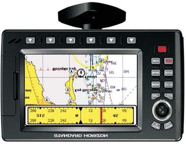
9 1. INTRODUCTION Congratulations on your purchase of the Standard Horizon GPS Chart Plotter. Whether this is your first GPS Chart Plotter, or if you have other STANDARD HORIZON equipment, the STANDARD HORIZON organization is committed to ensuring your enjoyment of this GPS Chart Plotter. STANDARD HORIZON technical support personnel stand behind every product we sell, and our Product Support team invites you to contact us should you require technical advice or assistance, at 800/ , or 1.0 GENERAL INFORMATION The CP180, CP300 (with external GPS antenna) and CP180i, CP300i (with internal GPS antenna) are precision-crafted GPS Chart Plotters with high-performance receiver for the Global Positioning System (WAAS GPS) constellation of satellites, providing precise location data with a host of navigation features. Ideal for nautical use and sealed against water ingress. The GPS Chart Plotter is housed in a rugged, impact-resistant case with outstanding ergonomic design, for effortless operation. The advanced features of the GPS Chart Plotter include: Direct sunlight viewable color LCD display Capable of using the Optional FF520 50/200kHz BLACK BOX FISH FINDER C-MAP NT + /MAX cartography compatible Improved Worldwide background showing detail up to 2.0 NM GPS WAAS Smart Antenna, bracket and flush mounting hardware (FOR CP180 AND CP300 ONLY) for CP180/CP180i: 600 Waypoints (Marks) / 20 Routes storage for CP300/CP300i: 3000 Waypoints (Marks) / 50 Routes storage User selectable data fields NMEA Data pages for CP180/CP180i: 3 NMEA Outputs and 2 Inputs (2 Inputs for CP180i) for CP300/CP300i: 5 NMEA Outputs and 3 Inputs (2 Inputs for CP300i) Connections to and from STANDARD HORIZON DSC VHF s for Distress and Position Request calls 3 year limited warranty, lifetime flat rate NOTE The screen imagines on this manual refer to the CP180/CP180i Chart Plotters unless specified. 1.1 PACKING LIST When the package containing the GPS Chart Plotter is first opened, please check for the following contents. If any parts are missing contact the dealer this GPS Chart Plotter was purchased from. Accessories and replacement parts may be ordered from STANDARD HORIZON s Parts Department at 767/ ext 6800 or at yaesuparts@vxstdusa.com. GPS Chart Plotters Page 11
10 1.1.0 CP180/CP180i Packing List PART CODE S A S S T S EM016N550 XUCMP0058 EM023U100 EM023U500 ITEM External bracket Mounting knob with two washers Dust cover Power data cable Flush mounting screws (CP180 ONLY) Flush mount template (CP180 ONLY) GPS WAAS Smart antenna Owner s Manual Quick Reference Guide CP300/CP300i Packing List PART CODE S A S S T T S EM022U500 XUCMP0052 XUCMP0058 EM022U100 EM022U510 ITEM External bracket Mounting knob with two washers Dust cover PWR & ACC 1 cable ACC 2 cable Flush mounting screws (CP300 ONLY) Flush mount template (CP300 ONLY) 2 Amp fuse and holder GPS WAAS Smart antenna (CP300 ONLY) Owner s Manual Quick Reference Guide 1.2 OPTIONAL ACCESSORIES CP300/CP300i Optional Accessories PARTS NAME ACVC10 FF520 DST520 DST521 DST523 DST525 DST526 DST527 DST528 ITEM Video Adapter cable (AAF69X001) 50/200kHz Black Box Fish Finder 500W 2" Nylon thru hull depth temp Transducer 500W Transom mount depth, speed temp Transducer 500W 2" Bronze thru hull depth temp Transducer 500W In-Hull Transducer 500W 2" Bronze thru hull depth, speed temp Transducer 1000W In-Hull depth Transducer 1000W Bronze long stem depth temp Transducer Page 12 GPS Chart Plotters
11 2. GETTING STARTED NOTE Throughout this Owner s Manual same conventions are used. See the legend below: [MENU]If you see brackets around a bold and capital letter word this refers to a key press. [CHART] If you see brackets around a bold and small capital letter word this refers to a Soft Key press. GENERAL SETUP When a word(s) is bold capital letters and underlined, this refers to a menu selection item. 2.0 MOUNTING THE GPS CHART PLOTTER The CP180 and CP300 are supplied with hardware for bracket or flush mounting, the CP180i and CP300i are is supplied with the hardware for bracket mounting due to the internal design of the GPS antenna. Below are pictures showing actual examples of the two types of installation. NOTE The GPS Chart Plotter with internal GPS antenna is designed to be bracket mounted only. Do not flush mount or GPS performance may be dramatically reduced or not receive a fix. 2.1 BRACKET MOUNTING The CP180/CP180i and CP300/CP300i can be mounted using the supplied swivel mounting bracket. Before installing ensure the area the bracket is mounted to is strong enough to support the weight of the GPS Chart Plotter especially while under way. After the location is found, attach the mounting base to the area using the supplied hardware. Figure Example of Bracket installation (CP180i on the left side and CP300i on the right side) GPS Chart Plotters Page 13
12 2.2 CP180 AND CP300 FLUSH MOUNTING The CP180 and CP300 are supplied with a flush mount template for the cutout hole and screw holes required to install the GPS Chart Plotter. NOTE Before drilling holes make sure there is enough room to mount the GPS Chart Plotter and there are no obstructions. 1. After a location is found, peel the template label from the backing and apply the label to the mounting area. 2. Drill a hole in one area of the cutout area that will allow the blade of a jig saw to be inserted. Insert and cut out the area on the panel using the jig saw. 3. Next drill the four holes required to insert the GPS Chart Plotter with the mounting studs. 4. Install the mounting studs on the GPS Chart Plotter and insert into the mounting hole. 5. Attach the GPS Chart Plotter to the mounting location by attaching the supplied hardware to the mounting studs. Figure Example of Flush installation (CP180 on the left side and CP300 on the right side) 2.3 MOUNTING THE CP180 OR THE CP300 EXTERNAL GPS ANTENNA The CP180 and CP300 are supplied with a external GPS WAAS antenna with 30 feet of routing cable. This antenna is designed to be mounted on a base, installed on an extension or even flush mounted. Page 14 GPS Chart Plotters
13 Choose a location for the antenna that has a clear view of the sky and is not located within 3 FT of Radar or other transmitting antennas. Ensure there are no major obstructions or fixtures in the immediate proximity to the antenna. The antenna relies on direct line of sight satellite reception. If you are unsure of the chosen location, temporarily mount the antenna in the desired location to verify correct operation. If mounted close to Radar, after the GPS Chart Plotter has a fix, turn on the Radar to ensure the GPS Chart Plotter holds the fix (use the GPS Status Page). The thread used on the antenna is an industry standard (1inch 14TPI) used on a wide range of mounting brackets. Due to the manufacturing process of these mounting brackets, the antenna may not tighten all the way down onto all the threads. This is no concern however as the antenna must be tightened until the antenna stops rotating. NOTE The antenna cable can be cut and spliced to ease installation. Care must be taken when reconnecting the antenna cable to protect from water and corrosion Flush mounting the antenna NOTE Before drilling holes, it is recommended the antenna be positioned where the location is planned, cable connected to the GPS Chart Plotter and power turned on to ensure a GPS Fix is received. 1. Remove the threaded base from the antenna dome. 2. To ease installation a flush mounting template for the antenna has been included. 3. Apply the mounting template sticker to the area that was verified for GPS reception. 4. Then, drill out the 0.63 (16mm) and 0.16 (4mm) holes, and remove the template. 5. Insert the cable into the 0.63 (16mm) hole and route to the GPS Chart Plotter. 6. Apply a small amount or RTV to the under side of the antenna. 7. Place the antenna and then screw it into place using the screws. NOTE In some cases the screw may not be long enough, if this happens simply apply more RTV to the underside of the antenna to glue it into place. Figure Installing the GPS WAAS Smart Antenna (I) 0 4 mm [0.155"] 0 16 mm [0.63"] or greater 0 4 mm [0.155"] 0 4 mm [0.155"] GPS OVERALL SHAPE Figure 2.3.0a - Installing the GPS WAAS Smart Antenna (II) GPS Chart Plotters Page 15
14 2.4 CONNECTIONS The GPS Chart Plotter has connectors that are used to connect to the power supply, GPS Antenna (CP180 AND CP300 ONLY) optional FF520 50/200kHz BLACK BOX FISH FINDER and to NMEA devices such as VHF s, AIS Receivers, digital instruments and autopilots. NOTE The GPS Chart Plotter can send many sentences to external NMEA devices. The NMEA Output wires are Yellow, Brown and White. If you have connected devices as shown in the below table and need to feed NMEA to other devices (Autopilot, RADAR ) you can parallel wires from the Yellow, Brown or White wires Connection Table For CP180/CP180i 12VDC Power and NMEA PWR & ACC 1 Cable Pin Wire Color Description Connection Example Additional Comments 1 Black Battery Ground Connect to Battery Ground 2 Red Battery Positive Connect to Battery Positive 3 Green NMEA Common Common (ground) for NMEA devices 4 Blue Port1 Input Connect to Output of NMEA device Default is NMEA0183* 5 Brown Port1 Output Connect to Input of NMEA device Default is NMEA0183 with GLL, RMB, RMC and XTE sentences 6 Gray Port2 Input Connect to Output of NMEA device Default is NMEA0183** 7 White Port2 Output Connect to Input of NMEA device Default is NMEA0183 with GLL, RMB, RMC and XTE sentences 8 Yellow Port3 Output Connect to Output of NMEA device Default is NMEA0183 with APA, APB, XTE, COG and BOD sentences*** *NOTE: AIS RECEIVER OPTION When an optional AIS rceiver is connected, Port 1 of the NMEA in/out Communication setup menu must be changed to AIS as shown below for communications. 1. From the Chart page, press [MENU]. Move the ShuttlePoint knob to highlight SETUP MENU and press [ENT]. 2. Move the ShuttlePoint knob to highlight ADVANCED SETUP and press [ENT] or move the ShuttlePoint knob to the right. 3. Move the ShuttlePoint knob to highlight IN/OUT CONNECTIONS and press [ENT] or move the ShuttlePoint knob to the right. 4. Move the ShuttlePoint knob to highlight PORT 1 INPUT and press [ENT] or move the ShuttlePoint knob to the right. 5. Move the ShuttlePoint knob up/down to select AIS and press [ENT] or move the ShuttlePoint knob to the right. 6. Press [CLR] or move the ShuttlePoint knob to the left until the Chart page is shown. **NOTE: FF520 FISH FINDER OPTION When a FF520 is connected to the GPS Chart Plotter, Port 2 of the NMEA in/out Communication setup menu must be changed to FF520 as shown below for communications. 1. From the Chart page, press [MENU]. Move the ShuttlePoint knob to highlight SETUP MENU and press [ENT]. 2. Move the ShuttlePoint knob to highlight ADVANCED SETUP and press [ENT] or move the ShuttlePoint knob to the right. 3. Move the ShuttlePoint knob to highlight IN/OUT CONNECTIONS and press [ENT] or move the ShuttlePoint knob to the right. 4. Move the ShuttlePoint knob to highlight PORT 2 INPUT and press [ENT] or move the ShuttlePoint knob to the right. Page 16 GPS Chart Plotters
15 5. Move the ShuttlePoint knob up/down to select FF520 and press [ENT] or move the ShuttlePoint knob to the right. 6. Press [CLR] or move the ShuttlePoint knob to the left until the Chart page is shown. ***NOTE: AUTOPILOT CONNECTION Care must be taken when connecting the GPS Chart Plotter to an autopilot. Normally Port 3 (Yellow wire) will be used to connect to an Autopilot input, however older autopilots may not be able to read the sentences due to the talker ID that is being used (II Integrated Instrument). If the autopilot connections are made to Port 3 (Yellow wire) and the autopilot is not reading the sentences, change the connections to Port 1 (Brown) or 2 (White) and change the sentences to APA, APB, XTE, COG and BOD. Smart GPS Cable FOR CP180 and CP300 Pin Wire Color Description 1 Red Battery Positive 2 Green Smart GPS NMEA Output 3 Brown Smart GPS NMEA Input 4 NC 5 NC 6 Black/Yellow Battery Ground Connection Table For CP300/CP300i 12VDC Power and NMEA PWR & ACC 1 Cable Pin Wire Color Description Connection Example Additional Comments 1 Black Battery Ground Connect to Battery Ground 2 Red Battery Positive Connect to Battery Positive 3 Green NMEA Common Common (ground) for NMEA devices 4 Blue Port 1 Input Connect to Output of NMEA device Default is NMEA Brown Port 1 Output Connect to Input of NMEA device Default is NMEA0183 with GLL, RMB, RMC and XTE sentences 6 Gray Port 2 Input Connect to Output of NMEA device Default is NMEA0183* 7 White Port 2 Output Connect to Input of NMEA device Default is NMEA0183 with GLL, RMB, RMC and XTE sentences 8 Yellow Port 3 Output Connect to Output of NMEA device Default is NMEA0183 with APA, APB, XTE, COG and BOD sentences *NOTE: FF520 FISH FINDER OPTION When a FF520 is connected to the GPS Chart Plotter, Port 2 of the NMEA in/out Communication setup menu must be changed to FF520 as shown below for communications. 1. From the Chart page, press [MENU]. Move the ShuttlePoint knob to highlight SETUP MENU and press [ENT]. 2. Move the ShuttlePoint knob to highlight ADVANCED SETUP and press [ENT] or move the ShuttlePoint knob to the right. 3. Move the ShuttlePoint knob to highlight IN/OUT CONNECTIONS and press [ENT] or move the ShuttlePoint knob to the right. 4. Move the ShuttlePoint knob to highlight PORT 2 INPUT and press [ENT] or move the ShuttlePoint knob to the right. 5. Move the ShuttlePoint knob up/down to select FF520 and press [ENT] or move the ShuttlePoint knob to the right. 6. Press [CLR] or move the ShuttlePoint knob to the left until the Chart page is shown. GPS Chart Plotters Page 17
16 NMEA ACC 2 Cable Pin Wire Color Description Connection Example Additional Comments 1 Black NC 2 Red NC 3 Green NMEA Common Common (ground) for NMEA devices 4 Blue Port 4 Input Connect to Output of NMEA device Default is NMEA0183** 5 Brown Port 4 Output Connect to Input of NMEA device Default is NMEA0183 with GLL, RMB, RMC and XTE sentences 6 Gray Port 5 Input Connect to Output of NMEA device Default is NMEA White Port 5 Output Connect to Input of NMEA device Default is NMEA0183 with GLL, RMB, RMC and XTE sentences 8 Yellow NC **NOTE: AIS RECEIVER OPTION When an optional AIS rceiver is connected, Port 4 of the NMEA in/out Communication setup menu must be changed to AIS as shown below for communications. 1. From the Chart page, press [MENU]. Move the ShuttlePoint knob to highlight SETUP MENU and press [ENT]. 2. Move the ShuttlePoint knob to highlight ADVANCED SETUP and press [ENT] or move the ShuttlePoint knob to the right. 3. Move the ShuttlePoint knob to highlight IN/OUT CONNECTIONS and press [ENT] or move the ShuttlePoint knob to the right. 4. Move the ShuttlePoint knob to highlight PORT 4 INPUT and press [ENT] or move the ShuttlePoint knob to the right. 5. Move the ShuttlePoint knob up/down to select AIS and press [ENT] or move the ShuttlePoint knob to the right. 6. Press [CLR] or move the ShuttlePoint knob to the left until the Chart page is shown. Video Connector Pin Description Connection Example 1 Ground Connect to Video Signal Ground of DVD/VCR/Video Cameras / 12 VDC Connect to Video Cameras Power Input 3 Video Signal + Connect to NTSC Video Signal + of DVD/VCR/Video Cameras Connection For CP180/CP180i DC Power Connection Page 18 GPS Chart Plotters
17 Connection of the FF520, AIS receiver, VHF and Autopilot NOTE Port 2 input and output is used by the optional FF520. In the diagram above you will notice Port 2 Input and Output wires are shown in gray and not used. AIS Setup The CP180 or CP180i has to be setup to be able to receive NMEA information from the AIS receiver. 1. Press [Menu], move the ShuttlePoint knob to highlight SETUP MENU and press [ENT]. 2. Move the ShuttlePoint knob to highlight ADVANCED SETUP and press [ENT] or move the ShuttlePoint knob to the right. 3. Move the ShuttlePoint knob to highlight IN/OUT CONNECTIONS and press [ENT] or move the ShuttlePoint knob to the right. 4. Move the ShuttlePoint knob to highlight PORT 1 INPUT and press [ENT] or move the ShuttlePoint knob to the right. 5. Move the ShuttlePoint knob up/down to select AIS and press [ENT] or move the ShuttlePoint knob to the right. GPS Chart Plotters Page 19
18 NOTE If an AIS receiver is not connected, Port 1 Input can be connected to most DSC VHF s for position polling Connection For CP300/CP300i DC Power Connection Connection a VideoCamera, FF520, AIS receiver, VHF and Autopilot Page 20 GPS Chart Plotters
19 NOTE Port 2 Input and Output is used by the optional FF520. In the diagram above you will notice Port 2 Input and Output wires are shown in gray and not used. Port 4, and 5 Outputs are can be connected to NMEA devices capable of listening to NMEA 0183 sentences. Port 4, and 5 Inputs can be connected to NMEA devices capable of outputting to NMEA 0183 sentences. The Input and Output baud rate for each port are set using the Advanced Setup>In/Out Connections menu. For example if Port 1 is set for AIS 38400, the Input and Output both operate at baud. AIS Setup The CP300 or CP300i has to be setup to be able to receive NMEA information from the AIS receiver. 1. Press [Menu], move the ShuttlePoint knob to highlight SETUP MENU and press [ENT]. 2. Move the ShuttlePoint knob to highlight ADVANCED SETUP and press [ENT] or move the ShuttlePoint knob to the right. 3. Move the ShuttlePoint knob to highlight IN/OUT CONNECTIONS and press [ENT] or move the ShuttlePoint knob to the right. 4. Move the ShuttlePoint knob to highlight PORT 4 INPUT and press [ENT] or move the ShuttlePoint knob to the right. 5. Move the ShuttlePoint knob up/down to select AIS and press [ENT] or move the ShuttlePoint knob to the right. 2.5 BATTERY CONNECTIONS 1. The GPS Chart Plotters are supplied with a fuse and holder. This fuse should be installed into the Black wire to protect the NMEA Output/Input circuits from becoming damaged. 2. Connect the Red and Black wires from the GPS Chart Plotter to a 12VDC source directly as possible. 2.6 NMEA CONNECTIONS The GPS Chart Plotter can be connected to external devices with NMEA and display information, examples: GPS Chart Plotters Page 21
 on VHF radios.")
20 - DSC VHF Radio - Depth Sounder, Speed Log, Wind Instrument, Autopilot etc. - Personal Computer - AIS receiver 2.7 GPS POSITION ON A VHF RADIO STANDARD HORIZON has pioneered Digital Selective Calling (DSC) on VHF radios. Advancements in DSC have made it possible to show the coordinates of a vessel that has transmitted a DSC Distress Call or even Poll the location of another vessel and show the position of that vessel on the display of STANDARD HORIZON VHFs. STANDARD HORIZON has taken this feature one step further, if the GPS Chart Plotters are connected to a STANDARD HORIZON DSC capable VHF, the vessel in Distress or the polled position of the vessel is shown on the display of the GPS Chart Plotter, making it easy to navigate to the location of the vessel. This is a great feature that could save someone s life or for anyone wanting to know the position of another vessel. Other DSC VHF Manufactures GPS Chart Plotter Description VHF Green NMEA Common Ground Connect to NMEA Ground Brown NMEA Positive Output Connect to NMEA Input Blue NMEA Positive Input * Connect to NMEA Output (if available) * Some manufacturers of DSC VHF s are not capable of receiving NMEA DSC sentences from the GPS Chart Plotter. Refer to the Owner s Manual and confirm the VHF can receive NMEA DSC and DSE sentences output by the brown wire. NOTE Refer to VHF Digital Selective Calling section for operation. 2.8 OPTIONAL BLACK BOX FISH FINDER STANDARD HORIZON offers an optional BLACK BOX FISH FINDER called the FF520. Please refer to the Owner's Manual supplied with the Fish Finder for connections and operation. Figure FF520 50/200kHz BLACK BOX FISH FINDER 2.9 OUTPUTTING NMEA TO A PERSONAL COMPUTER The GPS Chart Plotter can be connected to output Marks, Routes and tracks to many PC programs available. To send or receive User Points the PC Program must be able to receive NMEA WPL and RTE sentences. Refer to the table below for connection to a Serial DB9 connector. Pin PC DB9 connection NMEA connection 2 Receive Brown 3 Transmit Blue 5 Signal ground Green Page 22 GPS Chart Plotters

21 2.10 NMEA DATA PAGE The NMEA Data Page is very useful to see if a External device (example: Depth Sounder) is transmitting NMEA sentences to the GPS Chart Plotter. This page can also be used to see if the GPS Chart Plotter NMEA output is being loaded down by a external NMEA device the GPS Chart Plotter is connected to. Example: VHF Radio connected but the radio is not receiving a GPS Position. Usually the VHF radio will be connected to the Green and Brown wires. To check to see if the GPS Chart Plotter is transmitting the sentences: 1. Press [MENU]. Move the ShuttlePoint knob to highlight NMEA DISPLAY and press [ENT]. 2. Move the ShuttlePoint knob to highlight DATA and press [ENT]. 3. The NMEA DATA page is shown. 4. Connect the Blue Wire on the GPS Chart Plotter to the junction of the Brown wire and the VHF wire. The display should look similar to the picture below. ENTER TO STOP ZOOM IN TO CHANGE Port: NMEA1 Figure NMEA Data page 2.11 CP300/CP300i VIDEO INPUT By accessing this menu it is possible to see images on the CP300/CP300i display from an external video signal source, if connected to the CP300/CP300i. It allows the "picture-in-picture" functionality, so a Video Input image can be shown on a window and placed over the Chart, Navigation, Highway, Celestial and NMEA pages image at full screen. NOTE If the Video Input signals is not detected (E.g. the video camera is not connected to the Video Input connector), the VIDEO INPUT menu item will be grayed out Video Camera Input The CP300/CP300i has one connection for video camera. Any NTSC or PAL camera will operate correctly. To connect use the video output of the camera and connect to the optional ACVC10 cable VCR or DVD Input A VCR or DVD may be connected to Video port. The CP300/CP300i does not have speakers so the audio from the VCR or DVD would have to be routed to a stereo system. STANDARD HORIZON offers an optional cable called ACVC10 that allows any VCR or DVD to simply be plugged into the CP300/CP300i. GPS Chart Plotters Page 23
22 VCR/DVD Audio OUT Video Signal GND Video Signal OUT STEREO SYSTEM Figure VCR/DVD Input VIDEO CONNECTOR =GND 2=PWR+ 3=SIGNAL The CP300/CP300i has the capability to select the Video Input in three ways. I. From the menu 1. Press [MENU]. Move the ShuttlePoint knob to highlight SETUP and press [ENT]. 2. Move the ShuttlePoint knob to highlight VIDEO INPUT and press [ENT] or move the ShuttlePoint knob to the right. A menu appears with the following options: a. ACTIVATE VIDEO, the possible choices are Full Screen View, PiP (Picture in Picture) View and Auto Switch (*). If Full Screen View is chosen, the GPS Chart Plotter will show a warning message with the instructions to adjust the image from the Video Input. If the user agrees to proceed, the image from the video input will be shown. If Picture in Picture (PiP) View is chosen, a Video Input image can be shown on a window and placed over the selected page at full screen. By moving the ShuttlePoint knob, the PiP image is moved. When the focus is on the PiP image, press [CLR] to close the PiP image. If Auto Switch is chosen, all the menus will be closed and the video input will be shown switching between the Video Input Full View (if connected) and the selected page. See next section for details of setting up the switching times. If the user agrees to proceed, the image from the video input and the GPS Chart Plotter page will be shown intermittently. The intermittence time is selected by Switching Timeout item. b. SWITCHING TIMEOUT, the possible choices are 5,10,30 sec, 1, 5, 10 min. Allows selecting the timing to change from Video Input and GPS Chart Plotter display. c. RESTORE DEFAULTS, allows restoring the factory defaults for the Input picture adjustment. When Restore default is executed, the message OK is shown next to the selected menu item. NOTE (*) If the video signal is not present on the video connector, the corresponding item in the menu will be shown with a light color (to identify that the option is not available). II. Quick Activation by pressing [CLR] for 1 second Pressing and holding [CLR] for 1 second from the Chart page Display or from any main page (Navigation, Highway, Celestial, GPS Status, DSC, NMEA DISPLAY); the following Soft Keys are shown: [FULL SCREEN], [PIP VIEW], [AUTO SWITCH]. If no video signal is detected on the Video Input connector, the Soft Keys will be shown in light color in order to identify that they are not active. III. Quick Activation by Soft Keys It is possible to assign the Video Input mode to any of the Soft Keys. Press one of the Soft Keys, the Soft Keys functions are shown. Pressing and holding for 1 second one of the Soft Keys, the Soft Keys customization list will be shown. By selecting VIDEO option it will be possible to assign the Soft Key to execute the Video Input function. Once the Soft Key has been assigned to Video Input, its label will show the message [VIDEO]. If [VIDEO] is pressed, the Soft Keys will be assigned this way: [FULL SCREEN], [PIP VIEW], [AUTO SWITCH]. From now on, the functioning is identical to case II. Page 24 GPS Chart Plotters
23 2.12 DEMO MODE (FOR DEALER USE) NOTE When the PIP video window is shown, the ShuttlePoint knob can be used to move the position of the PIP window or move the cursor around the chart page. By default the PIP window is controlled by the ShuttlePoint knob. To change so the chart cursor can be moved, press any Soft Key, then press [VIDPAGE]. To change back to control the PIP window press any Soft Key, then press [VIDPAGE] again. NOTE When the PIP window is shown, the cursor and the vessels position may be shown under the PIP window. In Demo mode the GPS Chart Plotter automatically places a Destination point on the Chart page and simulates navigation to the point. Also, the active page changes automatically every 10 seconds. The pages are shown in the following order: Start-up screen, GPS Status, Chart/General window, Chart/Compass tape, Chart/Fish, Full page Fish, Navigation page, Highway Page, Celestial page, NMEA Page. NOTE This mode is use by selling dealers to promote the features of the GPS Chart Plotter when on a retail shelf. The Demo mode can be selected from the Simulation Menu following the procedure: 1. Press [MENU]. Move the ShuttlePoint knob to highlight SETUP MENU and press [ENT]. 2. Move the ShuttlePoint knob to highlight ADVANCED SETUP and press [ENT] or move the ShuttlePoint knob to the right. 3. Move the ShuttlePoint knob to highlight SIMULATION and press [ENT] or move the ShuttlePoint knob to the right. 4. Move the ShuttlePoint knob to highlight DEMO MODE and press [ENT] or move the ShuttlePoint knob to the right to show the popup window. 5. Move the ShuttlePoint knob to select On and press [ENT] or move the ShuttlePoint knob to the right. 6. Demo mode is now activated. Once the Demo mode is enabled, pressing any key it is possible to temporally exit and returns to GPS Chart Plotter normal operation, but if you do not touch any key for 30 seconds Demo mode re-starts. To disable Demo mode follow the procedure above selecting Off at point 5. GPS Chart Plotters Page 25
24 Page 26 GPS Chart Plotters
25 3. CONTROLS AND INDICATORS NOTE This section defines each control of the GPS Chart Plotter. For instructions, refer to Getting Started and Advanced Settings sections of this Owner's Manual. 3.0 CONTROLS AND CONNECTIONS The GPS Chart Plotter is controlled by using the keys located on the front panel. These labelled keys are dedicated to specific functions. As you press a key, a single audio beep confirms the key action; every time a key press is not valid, three rapid beeps sound to indicate that the key action is not valid. There is also a ShuttlePoint knob to move the cursor across the screen. The ZOOM IN and ZOOM OUT keys Pressing [ZOOM IN] shows more detail of a smaller area, by changing the chart scale and zooming in on your display. Press [ZOOM OUT] to change the scale and show a wider, otherwise less detailed view. Pressing and holding [ZOOM IN]/[ZOOM OUT] allows for quick zoom, that is the fast change of the chart scale where only the land areas are drawn. When [ZOOM IN]/[ZOOM OUT] is released all map details are shown. NOTE The GPS Chart Plotter contains a Worldwide background that allows you to zoom into 2NM. For more detail, a C-MAP NT + /MAX C-CARD must be purchased and installed. The ShuttlePoint knob The ShuttlePoint knob moves the cursor about on the display screen, quickly and accurately. It also scrolls the desired option in the menu page(s). It changes the Chart Plotter from Home Mode to Cursor Mode on the Chart Screen. For a detailed explanation of Cursor VS Home mode refer to section The ENT key Press [ENT] to select the desired option or to confirm selection. The CLR key Press [CLR] to set Home mode. Also press [CLR] to exit from menu or data windows or to leave a menu without making changes, to abort selected function or to step backward from a selection made in the menu. The MENU key Selects the Main Menu. When in the Setup Menu mode, moving the ShuttlePoint knob to the right enters a selection, moving the knob to the left clears the function. Press and hold [MENU] for 3 seconds allows you to change the fields contained within the data windows while on the Chart, Navigation, Highway, GPS Status or NMEA Display Page. Press and hold [MENU] for 3 seconds from Navigation, Highway, GPS Status, NMEA and Chart pages allows the data fields to be customize. The GOTO key This key is very useful when you desire to start navigating (goto) to a destination point. When pressed, a popup window will be shown allowing you to select to start navigating to the position of the cursor, Mark or Route. GPS Chart Plotters Page 27
26 To stop navigation to a point, press [GO TO] and select Stop on the pop-up window. The MARK key Places a Mark under the ships position when in Home Mode, or when the cursor is shown will place a Mark under the location of the cursor. The ROUTE key When pressed places a Waypoint. Succeeding presses place more Waypoints to form a Route. The PWR key and Lamp/Contrast Press and hold [PWR] to turn the GPS Chart Plotter on or off. Once on, press [PWR] to show the Contrast and Lamp popup window. The MOB key When pressed the GPS Chart Plotter automatically places a Mark on the Chart page under the boats position and all navigation is towards the position of the MOB Mark to aid in the rescue or a person that may have fallen overboard. The INFO key When pressed shows information on the selected point The CP300/CP300i Soft Keys The 6 keys in the bottom of the front panel (hereinafter named Soft Keys) have different functions associated depending on the software: their labels are shown on the screen immediately above the keys (the user can customize the function associated). The Soft Keys These keys allow quick selection to the many pages the GPS Chart Plotter has. These keys can be customized to your preference, however from the factory the keys are preprogrammed with the following pages. From left to right VIDEO, NAV, HIGHWAY, CELEST, CHART, LIST. Press any of the keys and you will see popup windows above the keys. To goto a specific page press the key with the desired popup window. The popup windows will automatically disappear if a key is not pressed or can be removed by pressing [CLR]. 3.1 GETTING STARTED The Getting Started section will take you through the frequently used operations and assist you to customize the look of the GPS Chart Plotter Power On, Off and ShuttlePoint knob operation 1. Press and hold [PWR] until the display shows the start-up page. To turn off, press and hold [PWR] until the display turns off. 2. When the power is first turned on two pages the start-up page (see the following picture) and the Caution page are briefly shown before the GPS Status page. Page 28 GPS Chart Plotters


27 Figure Example of Start-Up page on CP When the GPS Chart Plotter is first turned on it will take some time for the GPS to acquire a fix of your position. Look closely at the GPS Status page and you will see satellites and relative signal strengths. After a fix is received the GPS Chart Plotter will automatically switch to the Chart page with the ships icon centered on the screen AM Cursor Figure 3.1.0a - GPS Status and Chart pages 2 Ships Icon 3 Cursor window 4. On the Chart page the ShuttlePoint knob is used to pan around the chart. Move the ShuttlePoint knob to the left and you will notice a cross hair appears, this is called the cursor. 5. When you move the ShuttlePoint knob you will notice DST and BRG values in the Data window change. This shows the Distance and Bearing from the GPS Fix of your vessel to the position of the Cursor. 6. If the cursor is moved to the edge of the screen the GPS Chart Plotter will automatically pan in the desired direction Cursor Vs. Home Mode Cursor Mode When the cursor is shown on the Chart page, this is called Cursor mode. In Cursor mode the position of the vessel will not stay in the center of the page and will move right off the edge of the screen (as your boat moves) Cursor mode allows you to pan around and look at areas on the map. In this mode your can also measure distance and bearings from your current position. Home mode When the ships icon is shown on the Chart page (cursor is not shown) you are in Home GPS Chart Plotters Page 29
![mode. Now as the ship moves through the water the vessels position will be kept in the center of the display. NOTE To change from Cursor mode to Home mode press [CLR]. 3.1.](/docs-images/89/99007054/images/28-0.jpg "2 Cursor and Menu selection speed The GPS Chart Plotter allows you to control the speed the Cursor moves when the ShuttlePoint knob is pressed. To change the speed: Figure 3.1.2 - Cursor Speed menu 1.")
![Press [MENU]. Move the ShuttlePoint knob to highlight SETUP MENU and press [ENT]. 2. Move the ShuttlePoint knob to highlight GENERAL SETUP and press [ENT] or move the ShuttlePoint knob to the right.](/docs-images/89/99007054/images/28-1.jpg "3. Move the ShuttlePoint knob to highlight CURSOR SPEED and press [ENT] or move the ShuttlePoint knob to the right. 4.")
28 mode. Now as the ship moves through the water the vessels position will be kept in the center of the display. NOTE To change from Cursor mode to Home mode press [CLR] Cursor and Menu selection speed The GPS Chart Plotter allows you to control the speed the Cursor moves when the ShuttlePoint knob is pressed. To change the speed: Figure Cursor Speed menu 1. Press [MENU]. Move the ShuttlePoint knob to highlight SETUP MENU and press [ENT]. 2. Move the ShuttlePoint knob to highlight GENERAL SETUP and press [ENT] or move the ShuttlePoint knob to the right. 3. Move the ShuttlePoint knob to highlight CURSOR SPEED and press [ENT] or move the ShuttlePoint knob to the right. 4. The menu now shows two selections, CHART and MENU which allows the Cursor Speed to be selected to High, Medium or Low on Chart page or within the menus. 5. With CHART or MENU selected, press [ENT] or move the ShuttlePoint knob to the right. Move the ShuttlePoint knob to the desired setting and press [ENT] or move the ShuttlePoint knob to the right. 6. Press [CLR] until the menu disappears or an easier method is to press the ShuttlePoint knob to the left a few times. 7. Move the cursor on the Chart page and see if the speed is to your liking Changing the Ships Icon The cursor may be changed to any of the following: Figure Ship icons 1. Press [MENU]. Move the ShuttlePoint knob to highlight SETUP MENU and press [ENT]. 2. Move the ShuttlePoint knob to highlight GENERAL SETUP and press [ENT] or move the ShuttlePoint knob to the right. Page 30 GPS Chart Plotters
![3. Move the ShuttlePoint knob to highlight SHIP ICON and press [ENT] or move the ShuttlePoint knob to the right to show the popup window with ship icons. 4.](/docs-images/89/99007054/images/29-0.jpg "Move the ShuttlePoint knob to select the desired icon and press [ENT] or move the ShuttlePoint knob to the right to select a new icon. 5.")
![Press [CLR] or move the ShuttlePoint knob to the left to exit the menu and show the Chart page. 3.1.](/docs-images/89/99007054/images/29-1.jpg "4 Changing the backlight and contrast With the GPS Chart Plotter is turned On, briefly press [PWR] to show the light and contrast popup window.")
29 3. Move the ShuttlePoint knob to highlight SHIP ICON and press [ENT] or move the ShuttlePoint knob to the right to show the popup window with ship icons. 4. Move the ShuttlePoint knob to select the desired icon and press [ENT] or move the ShuttlePoint knob to the right to select a new icon. 5. Press [CLR] or move the ShuttlePoint knob to the left to exit the menu and show the Chart page Changing the backlight and contrast With the GPS Chart Plotter is turned On, briefly press [PWR] to show the light and contrast popup window. Move the ShuttlePoint knob to the left or right to adjust the LCD backlight intensity or up or down to change the LCD contrast. Press [ENT] to set. Figure Backlight and Contrast adjustment Selecting North Up or Course Up The default selection is NORTH UP, however you may want the top of the Chart page oriented so it will always show the area ahead of the direction your vessel is travelling which is called COURSE UP. Figure Course Up/North Up menu 1. Press [MENU]. Move the ShuttlePoint knob to highlight SETUP MENU and press [ENT]. 2. Move the ShuttlePoint knob to highlight GENERAL SETUP and press [ENT] or move the ShuttlePoint knob to the right. 3. Move the ShuttlePoint knob to highlight COURSE UP/NORTH UP and press [ENT] or move the ShuttlePoint knob to the right. 4. Another popup window will be shown with NORTH UP and COURSE UP, move the ShuttlePoint knob to the desired selection and press [ENT] or move the ShuttlePoint knob to the right. 5. Press [CLR] or move the ShuttlePoint knob to the left to exit the menu and show the Chart page. NOTE When the GPS Chart Plotter is in COURSE UP mode a small arrow icon will be shown on the Chart page indicating the direction of North. GPS Chart Plotters Page 31

30 3.2 ADJUSTING THE TIME The time information supplied by the GPS satellites is in Universal Time Coordinates (UTC or Greenwich England Mean Time). To change the GPS Chart Plotter to read the correct time, first you must figure out the offset and if it is daylight savings time. For example on the West coast of the United States or Pacific Standard Time the offset needed would be 08:00 or 07:00 for daylight savings time, Eastern Standard Time 05:00 or 04:00 for daylight savings time. Figure Adjusting Time NOTE This map shows offset for standard time. For daylight saving time, subtract one hour from the offset time. Figure 3.2a - Time Setup menu 1. Press [MENU]. Move the ShuttlePoint knob to highlight SETUP MENU and press [ENT]. 2. Move the ShuttlePoint knob to highlight GENERAL SETUP and press [ENT] or move the ShuttlePoint knob to the right. 3. Move the ShuttlePoint knob to highlight TIME SETUP and press [ENT] or move the ShuttlePoint knob to the right. 4. Move the ShuttlePoint knob to highlight GPS TIME OFFSET and press [ENT] or move the ShuttlePoint knob to the right. 5. Move the ShuttlePoint knob down to select +00:00, press [ENT] and move the ShuttlePoint knob to the right to edit the number. 6. Look at the table and find the offset for your area. You will need to enter this offset to Page 32 GPS Chart Plotters

31 make the GPS Chart Plotter shows the correct time. 7. Move the ShuttlePoint knob to the +. Move the ShuttlePoint knob up or down to change to the desired offset. 8. Next move the ShuttlePoint knob to the right to select Hours and move the ShuttlePoint knob up or down to change the hour. 9. Repeat this method to change the minutes, if necessary. 10. Once you have the correct GPS time offset, press [ENT] to set. 3.3 SELECTING LORAN TD OR OTHER COORDINATE SYSTEM The GPS Fix coordinates can be changed to show Latitude/Longitude, Loran TD s or UTM. Below is the window that will appear when customizing the Coordinate System. Figure Coordinate System menu 1. Press [MENU]. Move the ShuttlePoint knob to highlight SETUP MENU and press [ENT]. 2. Move the ShuttlePoint knob to highlight ADVANCED SETUP and press [ENT] or move the ShuttlePoint knob to the right. 3. Move the ShuttlePoint knob to highlight NAVIGATE and press [ENT] or move the ShuttlePoint knob to the right. 4. Move the ShuttlePoint knob to highlight COORDINATE SYSTEM and press [ENT] or move the ShuttlePoint knob to the right. 5. Move the ShuttlePoint knob to highlight the desired coordinate type and press [ENT] or move the ShuttlePoint knob to the right. 6. Press [CLR] or move the ShuttlePoint knob to the left until the Chart page is shown. NOTE If the TD is selected, you should set the Chain, Pair, ASF1, ASF2 and Alter. If the TD numbers are not correct the Pair letters may be backwards. Reversing the two letters usually solves this issue. Example Y/Z change to Z/Y. 3.4 CHANGING THE CHART COLOR The GPS Chart Plotter has preprogrammed settings allowing you to customize the look of the Chart page. The default is Sunlight however there are other settings; Normal, Classic and Night. Night is very useful during evening hours so not to impair night vision. GPS Chart Plotters Page 33
![Figure 3.4 - Display Color menu 1. Press [MENU]. Move the ShuttlePoint knob to highlight SETUP MENU and press [ENT]. 2.](/docs-images/89/99007054/images/32-0.jpg "Move the ShuttlePoint knob to highlight GENERAL SETUP and press [ENT] or move the ShuttlePoint knob to the right. 3.")
![Move the ShuttlePoint knob to highlight DISPLAY COLOR and press [ENT] or move the ShuttlePoint knob to the right. 4.](/docs-images/89/99007054/images/32-1.jpg "A popup window will be shown with Normal, Classic, NOAA, Night and Sunlight.")
![Move the ShuttlePoint knob to the desired selection and press [ENT] or move the ShuttlePoint knob to the right. 5.](/docs-images/89/99007054/images/32-2.jpg "Press [CLR] or move the ShuttlePoint knob to the left to exit the menu and show the Chart page. 3.")


32 Figure Display Color menu 1. Press [MENU]. Move the ShuttlePoint knob to highlight SETUP MENU and press [ENT]. 2. Move the ShuttlePoint knob to highlight GENERAL SETUP and press [ENT] or move the ShuttlePoint knob to the right. 3. Move the ShuttlePoint knob to highlight DISPLAY COLOR and press [ENT] or move the ShuttlePoint knob to the right. 4. A popup window will be shown with Normal, Classic, NOAA, Night and Sunlight. Move the ShuttlePoint knob to the desired selection and press [ENT] or move the ShuttlePoint knob to the right. 5. Press [CLR] or move the ShuttlePoint knob to the left to exit the menu and show the Chart page. 3.5 SELECTING PAGES USING SOFT KEYS ON CP300/CP300i The Soft Keys located under the LCD on the CP300 and CP300i are used to select the pages quickly without the need to go into the menu. The default pages are VIDEO, CHART, NAV, HIGHWAY, CELESTIAL and NMEA DISPLAY. When one of the Soft Keys is pressed popup windows above each Soft Key are shown with the key description. Press the Soft Key with the desired page description and the GPS Chart Plotter will change to that page. Figure Screen display pages 3.6 CUSTOMIZING THE SOFT KEYS ON CP300/CP300i The Soft Keys (CP300 and CP300i) can be individually customized from the default pages (discussed above) to the following: CHART, CHART/COMPASS, CHART/HIGHWAY, NAVIGATION, HIGHWAY, CELESTIAL, GPS STATUS, DSC LOG, DSC DIRECTORY, Page 34 GPS Chart Plotters

33 NMEA DISPLAY, NMEA DATA, DEPTH TREND, WIND SPEED TREND, TEMP TREND, SOG TREND, MARKS/WAYPOINTS, USER C-CARD and VIDEO INPUT. When the Optional FF520 50/200kHz BLACK BOX FISH FINDER is connected, any Soft Key can be customized to show 50 or 200kHz full page, 50 or 200kHz Chart/Fish split screen and zoom screens. Figure Window options of the selected Soft Key on CP300/CP300i 1. To change, momentarily press any of the Soft Keys, then press and hold the Soft Key you want to customize. 2. A popup window will be shown with the above settings. 3. Move the ShuttlePoint knob up or down to select the desired page. 4. Press [ENT] or move the ShuttlePoint knob to the right to save the page to the selected Soft Key. 3.7 OTHER SETTINGS IN GENERAL SETUP MENU You will notice the GENERAL SETUP menu has other selections that allow you to customize: TIME SETUP Selects a sub-menu to allow the time setup. It is possible to set the GPS Time Offset, choosing the UTC or Local Time display, and the Time Format, switching 12 or 24 hours time format. DATE FORMAT Allows choosing date format MM-DD-YY or DD-MM-YY. COURSE UP/NORTH UP Selections are: North Up : The Top of the page is fixed to North Course Up: The top of the page is orientated to the direction the vessel is heading. KEYPAD BEEP Allows the beep produced when a key is pressed to be turned on or off. UNITS OF MEASURE Units of Measure can be selected for Distance, Speed, Depth, Altitude and Temperature. NAV AIDS PRESENTATION Allows the Nav Aids presentation to be drawn using NOAA symbology when US is selected or International symbols will be used when International is selected. When selected these functions affect how the icons for Lights, Signals, Buoys and beacons are displayed. DISPLAY COLOR Changes the background colors of the chart page to enhance the visibility of the screen depending on the surrounding light conditions. Normal is recommended when the GPS Chart Plotter is not exposed to the direct sunlight. When this mode is set the maps are displayed in order to use colors as similar as possible to ones used in the original paper charts. Classic uses vivid chart colors presentation. NOAA allows setting NOAA paper chart colors presentation. Night is recommended when the environment is dark in order to reduce the glare of the display. The GPS Chart Plotter displays maps and screen in darker colors. Sunlight (default) is designed to enhance the visibility of the screen when the GPS Chart Plotter is exposed to sunlight. The maps are much brighter than in the other modes and the depth areas are filled with the white color so different depth areas are not easily distinguishable. SHIP ICON Allows selection of one of 5 choices of ship icons that represent your vessels position shown on the chart page. GPS Chart Plotters Page 35
34 CURSOR SPEED MEASURE DISTANCE WINDOWS SETUP LANGUAGE AUTO INFO CURSOR WINDOW CURSOR POSITION COG TIME LINE Selects the preferred speed among Low, Medium and High for the cursor in the Chart page and within the menu. When this function is turned on allows a distance to be measured between two points using the ShuttlePoint knob and [ENT]. This menu selection allows the data windows to be customized on the Chart and Navigation pages. Allows changing the language for menus and data screens. By default when the cursor is moved over a buoy, Mark or other item a popup window will show information of the item. This menu item allows the window to be turned on or off. By default when the cursor is moved a window is shown with the lat/lon Distance and bearing from the vessels location to the cursor. This selection allows the window to be turned off. The position of the cursor (vessels location) can be customized so it centered in the middle or centered on the bottom of the chart page. The default is Center. Is a line projected from the vessel icon which indicates the distance your vessel will travel at the current speed. Selections are 2, 10, 30 minutes, 1, 2 hours and infinite. 3.8 INFORMATION PAGE From Main Menu page it is possible to select an Information page containing Software, Chart and Optional devices information. Figure Example of Information page on CP Press [MENU]. Move the ShuttlePoint knob to highlight SETUP MENU and press [ENT]. 2. Move the ShuttlePoint knob to highlight About... and press [ENT] or move the ShuttlePoint knob to the right. 3. The Information page appears on the screen (see the previous Figure). 4. Press [CLR] or move the ShuttlePoint knob to the left to exit and show the Chart page. Page 36 GPS Chart Plotters

![Move the ShuttlePoint knob to highlight FIND SERVICES and press [ENT]. 2. Move the ShuttlePoint knob to highlight PORT SERVICES and press [ENT] or move the ShuttlePoint knob to the right. 3.](/docs-images/89/99007054/images/35-1.jpg "A popup window will be shown with the Port Services. 4. Move the ShuttlePoint knob to highlight the desired Service and press [ENT]. 5.")
35 4. USING FIND SERVICES & MORE FUNCTION With a C-MAP NT + /MAX C-CARD installed the GPS Chart Plotter allows you to search for a Port Service, Port, Tide Stations, Wrecks, Obstructions, POIs, Lakes, User Points, or GPS Coordinates. 4.0 PORT SERVICES With a C-MAP NT + /MAX C-CARD installed, the GPS Chart Plotter can find Port Services contained on the map. 1. Press [MENU]. Move the ShuttlePoint knob to highlight FIND SERVICES and press [ENT]. 2. Move the ShuttlePoint knob to highlight PORT SERVICES and press [ENT] or move the ShuttlePoint knob to the right. 3. A popup window will be shown with the Port Services. 4. Move the ShuttlePoint knob to highlight the desired Service and press [ENT]. 5. Another popup window will show the name, distance and position of the Services closest to your location. 6. Using the ShuttlePoint knob, highlight the desired Service and press [ENT] which will show the name and phone number of the Service. 7. Press [CLR] which will show the available Services at the location. 8. Press [CLR] to show the actual position of the Services. Figure Port Services 4.1 OTHER AVAILABLE SEARCHES PORT : Shows the list of all ports stored on the C-CARD in distance order. Pressing [MENU] shows the list of all ports in alphabetic order; press [MENU] again to insert the name to search. TIDE STATIONS : Searches for the closest Tide Station and shows the information of the selected tide station. WRECKS : Searches for the closest Wreck. OBSTRUCTIONS : Searches for the closest Obstruction. LAKES INFORMATION : Searches and shows information on the selected Lake. LAKES BY NAME : Shows the list of all lakes stored on the C-CARD in alphabetic order. Pressing [MENU] to insert the Lake name. POINTS OF INTEREST : Searches and shows information on the selected Point Of Interest. USER POINTS : Searches and shows on the Chart page the closest User Points (Marks or Waypoints). COORDINATES : Searches and shows on the Chart page GPS Coordinates. GPS Chart Plotters Page 37


36 4.2 INFO ON LAKES Quick Info On Lakes Upon viewing the chart of a lake, you will click on to query the available information immediately displayed with many details. For example, see the following picture: Figure Example of Lakes info When the cursor is placed over the icon, the icons of the available services are shown: Figure 4.2.0a - Quick Info: available services If you press [ENT] all available information about the cartographic point under the cursor will be shown. See the next paragraph Full Info On Lakes The following is an example of Full Info on Lakes: Figure Example of Full Info page Page 38 GPS Chart Plotters
![To see the "Fishing" object press [MENU] (when the "Fishing" object is highlighted).](/docs-images/89/99007054/images/37-0.jpg "On the screen appears: Figure 4.2.")
37 To see the "Fishing" object press [MENU] (when the "Fishing" object is highlighted). On the screen appears: Figure 4.2.1a - Example of picture associated to the Fishing object GPS Chart Plotters Page 39
38 Page 40 GPS Chart Plotters
39 5. C-MAP MAX OVERVIEW 5.0 INSERTING THE C-CARD Hold the C-CARD by the long inclined side so that you can see the C-MAP label. Figure Inserting C-CARD Open the door, gently push the C-CARD into the slot: push the C-CARD in as far as it will go, then close the door. Figure 5.0a - Inserting C-CARD (Details) C-MAP MAX is a major evolution of the NT/NT + product technology. Key points are: New Data Features Tides and Currents (intuitive arrows show direction and strength) World Background Charts with terrestrial data Value Added Data (Pictures and Diagrams, Land Data) Enhanced Port Info New Presentation Features Clear Info (sophisticated "Human Dictionary" to translate Nav-Aid abbreviations found on paper charts) Dynamic Nav-Aids (an innovative and dynamic presentation mode) Flexi-Zoom (increased Under and Over Zoom between chart levels, resulting in optimal scale display for any situation) GPS Chart Plotters Page 41
40 Dynamic Elevation Data (optimized palettes for GPS Chart Plotters; includes new NOAA palette) Perspective View ("Real World" perspective view of the chart, updated real-time during navigation) MAX and NT/NT + C-CARD coexistence When NT + data and MAX data cover different areas, the GPS Chart Plotter receives data from both charts (depending on the current position). When NT + data and MAX data cover the same area, the GPS Chart Plotter receives data only from MAX chart. Page 42 GPS Chart Plotters
41 6. MAP FUNCTIONS 6.0 MAX FUNCTIONS MENU 1. Press [MENU]. Move the ShuttlePoint knob to highlight SETUP MENU and press [ENT]. 2. Move the ShuttlePoint knob to highlight MAX FUNCTIONS and press [ENT] or move the ShuttlePoint knob to the right. The MAX Functions menu appears on the screen: Figure Map Functions Menu on CP180/CP180i The available Functions are described in the following Zoom Type Allows zooming into our out on the chart page. Zoom Mode has two options; STANDARD (default) or FLEXI-ZOOM. When in FLEXI-ZOOM mode, a short [ZOOM...] push causes a change of chart, while a long [ZOOM...] push (press and hold) causes a pop-up window to be displayed on a corner of the screen. The window shows the current Zoom Factor. By pressing [ZOOM IN]/[ZOOM OUT] the map is expanded or compressed according to the zoom factor selected. The window is automatically closed if [ZOOM...] is not pressed for 2 seconds and the selected zoom factor will be used at the next zoom in/out. To activate this function follow the procedure: 1. Press [MENU]. Move the ShuttlePoint knob to highlight SETUP MENU and press [ENT]. 2. Move the ShuttlePoint knob to highlight MAX FUNCTIONS and press [ENT] or move the ShuttlePoint knob to the right. 3. Move the ShuttlePoint knob to highlight ZOOM TYPE and press [ENT] or move the ShuttlePoint knob to the right. 4. The menu now shows two selections, STANDARD or FLEXI-ZOOM. 5. Move the ShuttlePoint knob to select the selection and press [ENT]. 6. Press [CLR] until the menu disappears or an easier method is to move the ShuttlePoint knob to the left a few times Fonts & Symbols ON THE CP300/CP300i On MAX charts it is possible to set the size of all names and symbols drawn on the charts, selecting between Normal size (the regular characters size) and Large size. To activate this function follow the procedure: 1. Press [MENU]. Move the ShuttlePoint knob to highlight SETUP MENU and press [ENT]. 2. Move the ShuttlePoint knob to highlight MAX FUNCTIONS and press [ENT] or move the ShuttlePoint knob to the right. 3. Move the ShuttlePoint knob to highlight FONTS & SYMBOLS and press [ENT] or move the ShuttlePoint knob to the right. 4. The menu now shows two selections, NORMAL or LARGE. GPS Chart Plotters Page 43
![5. Move the ShuttlePoint knob to select the selection and press [ENT]. 6. Press [CLR] until the menu disappears or an easier method is to move the ShuttlePoint knob to the left a few times.](/docs-images/89/99007054/images/42-0.jpg "NORMAL size LARGE size Figure 6.0.1 - Example of Normal size (on the left side) and Large side (on the right side) settings 6.0.2 Perspective View Chart data may be projected in perspective mode during navigation.")

![Move the ShuttlePoint knob to highlight SETUP MENU and press [ENT]. 2. Move the ShuttlePoint knob to highlight MAX FUNCTIONS and press [ENT] or move the ShuttlePoint knob to the right. 3.](/docs-images/89/99007054/images/42-2.jpg "Move the ShuttlePoint knob to highlight PERSPECTIVE VIEW and press [ENT] or move the ShuttlePoint knob to the right. 4. The menu now shows two selections, ON or OFF. 5.")
42 5. Move the ShuttlePoint knob to select the selection and press [ENT]. 6. Press [CLR] until the menu disappears or an easier method is to move the ShuttlePoint knob to the left a few times. NORMAL size LARGE size Figure Example of Normal size (on the left side) and Large side (on the right side) settings Perspective View Chart data may be projected in perspective mode during navigation. This function allows setting the panoramic View of the chart. As the upper side of the map is more compressed than the lower side, a wider map area is visible. The perspective view allows showing more chart information immediately ahead and around the cursor. Figure Perspective View To activate this function follow the procedure: 1. Press [MENU]. Move the ShuttlePoint knob to highlight SETUP MENU and press [ENT]. 2. Move the ShuttlePoint knob to highlight MAX FUNCTIONS and press [ENT] or move the ShuttlePoint knob to the right. 3. Move the ShuttlePoint knob to highlight PERSPECTIVE VIEW and press [ENT] or move the ShuttlePoint knob to the right. 4. The menu now shows two selections, ON or OFF. 5. Move the ShuttlePoint knob to select the selection and press [ENT]. 6. Press [CLR] until the menu disappears or an easier method is to move the ShuttlePoint knob to the left until the chart page is shown Dynamic Nav-Aids This function allows the Nav-Aids to be turned On or Off. The blink period and color of each Nav-aid is read from the Nav-Aid attributes available on the data cartridge. When the ship is inside the Nav-Aid nominal range, the light of the Nav-Aid will start blinking. Page 44 GPS Chart Plotters
43 When Dynamic Nav-Aids option is set to On, when the flashing light is Off, or when fix position is out of the sector, the light color is displayed by using a faint light color. To activate this function follow the procedure below: 1. Press [MENU]. Move the ShuttlePoint knob to highlight SETUP MENU and press [ENT]. 2. Move the ShuttlePoint knob to highlight MAX FUNCTIONS and press [ENT] or move the ShuttlePoint knob to the right. 3. Move the ShuttlePoint knob to highlight DYNAMIC NAV-AIDS and press [ENT] or move the ShuttlePoint knob to the right. 4. The menu now shows two selections, ON or OFF. 5. Move the ShuttlePoint knob to select the selection and press [ENT]. 6. Press [CLR] until the menu disappears or an easier method is to move the ShuttlePoint knob to the left until the chart page is shown Safety Status Bar (DSI - Data Safety Indicator) When Safety Status Bar is On, a status bar with six boxes showing the status of certain functions is displayed. Any warning or alarm condition is identified by the red color to indicate possible risk. To activate this function follow the procedure: 1. Press [MENU]. Move the ShuttlePoint knob to highlight SETUP MENU and press [ENT]. 2. Move the ShuttlePoint knob to highlight MAX FUNCTIONS and press [ENT] or move the ShuttlePoint knob to the right. 3. Move the ShuttlePoint knob to highlight SAFETY STATUS BAR and press [ENT] or move the ShuttlePoint knob to the right. 4. The menu now shows the following selections: ON (The Safety Status Bar is shown), OFF (The Safety Status Bar is not shown), ICON (The Safety Status Bar is not shown, but a Warning alarm Icon is shown on the corner of the map screen as soon as any item controlled by the DSI function returns an alarm condition. The Warning Icon remains displayed until the alarm condition persists. Placing the cursor over this Icon, a quick help message is shown next to the Icon, allowing the Safety Status Bar to be shown. In this case - when the Safety Status Bar is opened via Warning alarm Icon - it is allowed to obtain information about each active Safety Status box (the red ones): it is possible to select them by ShuttlePoint knob movement left/right, and a list of active alarms is shown underneath the selected box. By pressing [CLR], the Safety Status Bar is removed from the screen. 5. Move the ShuttlePoint knob to select the selection and press [ENT]. 6. Press [CLR] until the menu disappears or an easier method is to press the ShuttlePoint knob to the left a few times. Boxes definition is as follows: Figure Safety Status Bar Zoom Normal: when the chart is displayed at normal scale. U. Zoom: red when the chart is under-zoomed out more than twice normal scale, gray otherwise. GPS Chart Plotters Page 45
44 O. Zoom: red when the chart is over-zoomed in more than twice normal scale, gray otherwise. Chart Lock: red when the chart is zoomed in more than twice normal scale, gray otherwise. NOTE U. Zoom, O. Zoom and chart lock are used with Flexi zoom selected. Best Map Red when a more detailed chart is available under the cursor position. Data Off Red when at least one of the following objects or layers is turned off (by the user): Depths/soundings; Wrecks/obstructions; Tracks/routes; Attention Areas; Nav-Aids. Declutter Displays red when clearing overlapping objects. Dangers Red when Guardian Technology detects one of the following objects: Land, Intertidal, Depth Area, Rocks, Obstructions, Shoreline Constructions, Fishing Facility, Wrecks, Dragged area, Diffusion area, Mooring facilities, Pingos and Production installations. Caution Red when Guardian Technology detects cautionary or restricted area Currents Prediction It is possible to see the variation of the Tidal arrows on the selected area at any given time. To activate this function follow the procedure: 1. Press [MENU]. Move the ShuttlePoint knob to highlight SETUP MENU and press [ENT]. 2. Move the ShuttlePoint knob to highlight MAX FUNCTIONS and press [ENT] or move the ShuttlePoint knob to the right. 3. Move the ShuttlePoint knob to highlight CURRENTS PREDICTION and press [ENT] or move the ShuttlePoint knob to the right. 4. A window is shown on the low-left side of the chart. On the CP300/CP300i, press [SET TIME] to set the date and time manually, and [INCR. TIME]/[DECR. TIME] to decrease/increase time; press [EXIT] to exit. On the CP180/CP180i press [ENT] to set the date and time manually, and [GOTO]/[MENU] to decrease/increase time; press [CLR] to exit Pictures & Diagrams Using C-Map MAX data cards allows you to show pictures or diagrams on the Chart Plotter display. These Pictures are typically used to facilitate the identification of cartographic objects or places around the map: they can be the landscape layout nearby a harbour, the shape of a bridge or of a buoy etc. On some objects, such as bridges, the image associated can represent the Diagram representing the shape of the objects and the various characteristics (length, height, type of bridge etc.). Page 46 GPS Chart Plotters


45 Figure Pictures and Diagrams The pictures or diagrams can be a MULTIMEDIA OBJECT or they can be associated to a generic cartographic object, like a port marina. How to show the pictures or diagrams of a Multimedia Object They are shown on the chart page with the camera icon Move the cursor over the camera icon. You will get the quick info on the object and there will be the camera icon on the top bar of the window: Figure 6.0.6a - Example of Quick Info on MULTIMEDIA object Press [IMAGE] on the CP300/CP300i or press [ENT] on the CP180/CP180i for 1 second to display the image on the screen; press [EXPAND] on the CP300/CP300i or [ENT] on the CP180/CP180i to open the Full info on the object: Figure 6.0.6b - Example of Full Info on MULTIMEDIA object On the Full Info, there will be the small camera icon on a corner of the square containing the object icon. To see the picture press [MENU] when the object with a picture is highlighted. When the picture is shown, it is possible to fit it to screen by pressing [ENT]. When the picture is shown, it is possible to change the contrast by pressing [ZOOM IN] or [ZOOM OUT]. When the picture is shown, it is possible to display the next picture associated, if any, by pressing the ShuttlePoint knob left or right. GPS Chart Plotters Page 47
46 6.0.7 Enhanced Port Info MAX charts include additional port services that were not present before. Additional attributes of Port Areas and Port Marinas have been included (Location, Country, Region, State, Harbour master telephone number etc.). Page 48 GPS Chart Plotters

47 7. CREATING MARKS Definitions: MARK Can be a stand alone position or be linked to a Route. A Mark is place on the Chart page using [MARK] or by entering in information in the MARK/WAYPONTS List NEW MARK selection. WAYPOINTS Always linked to a Route. Are placed on the Chart page using [ROUTE]. NOTE The difference between a Mark and a Waypoint is a. When a Route is created using WAYPOINTS and the ROUTE is deleted the WAYPOINTs are also deleted. b. If a Route is created using MARKS and the ROUTE is deleted the MARKs remain. 7.0 CREATING A NEW MARK USING THE CHART PAGE 1. Move the ShuttlePoint knob to the desired or approx. Lat/Lon and press [MARK]. 2. You will notice a Mark is placed under the location of the Cursor and a popup window is shown with the exact Lat/Lon of the Mark. 3. If the position is incorrect on the CP180/CP180i press [ENT], select EDIT using the ShuttlePoint knob and press [ENT]. On the CP300/CP300i, press [EDIT] that will allow you to change the position, Mark name, icon type and color of the icon. 1 Mark placed under Cursor 2 3 Lat/Lon of Mark, DST/BRG from vessel location ONLY for CP180/180i Press [ENT] to delete, to move, to edit a Mark or to show the Marks/Waypoint List (Directory) ONLY for CP300/300i Press Soft Key to show the Marks/Waypoint List,toedit, to move or to delete Mark Vessel location Figure Mark creation NOTE After entering in all the Marks it is a good practice to back up the points to a C-MAP User C-CARD. Refer to Section EDITING A MARK If a Mark has previously been created and you wish to Edit it, move Cursor over the top of the Mark. GPS Chart Plotters Page 49
![Figure 7.1 - Mark editing 1. After a Mark is created on the CP180/CP180i press [ENT], select EDIT using the ShuttlePoint knob and press [ENT].](/docs-images/89/99007054/images/48-0.jpg "On the CP300/CP300i press [EDIT] to show the edit popup window. 2. Use the ShuttlePoint knob to change to the Mark Icon, when finished press [ENT]. 3.")
![Move the ShuttlePoint knob to the right to select the Mark Name. Press [ENT] and the first digit in the name will be highlighted. 4.](/docs-images/89/99007054/images/48-1.jpg "Move the ShuttlePoint knob up or down to select the first character. 5. Move the ShuttlePoint knob to the right to select the next character. 6. Repeat steps 4 and 5 until the Mark name is shown.")
48 Figure Mark editing 1. After a Mark is created on the CP180/CP180i press [ENT], select EDIT using the ShuttlePoint knob and press [ENT]. On the CP300/CP300i press [EDIT] to show the edit popup window. 2. Use the ShuttlePoint knob to change to the Mark Icon, when finished press [ENT]. 3. Move the ShuttlePoint knob to the right to select the Mark Name. Press [ENT] and the first digit in the name will be highlighted. 4. Move the ShuttlePoint knob up or down to select the first character. 5. Move the ShuttlePoint knob to the right to select the next character. 6. Repeat steps 4 and 5 until the Mark name is shown. Press [ENT]. 7. Move the ShuttlePoint knob to the right and press [ENT] to change the Mark Icon s Color. 8. Move the ShuttlePoint knob to up/down, left/right to select the Mark Icon s Color. When finished press [ENT]. 9. Move the ShuttlePoint knob to the right to select the Lat/Lon and press [ENT]. 10. Move the ShuttlePoint knob up or down to select the first character. 11. Move the ShuttlePoint knob to the right to select the next character. 12. Repeat steps 10 and 11 until the desired position is shown. Press [ENT] and [CLR] to store the Mark Deleting a Mark or Waypoint Move the cursor over the Mark or Waypoint to delete. On the CP180/CP180i press [ENT], select DELETE using the ShuttlePoint knob and press [ENT]. On the CP300/CP300i, press [DELETE]. A Warning popup window will be shown. Select YES and press [ENT] Moving a Mark or Waypoint Place the cursor over the Mark or Waypoint which you want to move. On the CP180/CP180i press [ENT], select MOVE using the ShuttlePoint knob and press [ENT]. On the CP300/ CP300i, press [MOVE]. Use the ShuttlePoint knob to move the cursor. A dotted line, connecting the previous Waypoint position to the new position, is shown: Figure Moving Mark or Waypoint (I) Press [ENT] ([CLR] to abort the move), the Waypoint appears in the new position. Page 50 GPS Chart Plotters

 is shown c. HIDE - Mark or Waypoint is hidden d.")
49 Figure 7.1.1a - Moving Mark or Waypoint (II) 7.2 MARKS/WAYPOINTS LIST The MARKS/WPTS List shows all the Marks and Waypoints that have been stored into the GPS Chart Plotter. This page also allows you to: ICON Allows sorting by icon type FIND Searches through the Marks or Waypoints to find a point by name using the ShuttlePoint knob LOCATE Shows the position of a Mark or Waypoint on the Chart page EDIT Allows you to edit a previous stored Mark or Waypoint NEW MARK Allows entering in Marks, editing icon type and position MODE This selection controls how the Marks or Waypoints are shown on the Chart page. Selections are: a. SHOW - icon and name are shown b. ICON - only icon (no name) is shown c. HIDE - Mark or Waypoint is hidden d. SHOW ALL - All Marks or Waypoints are shown e. ICON ALL - All Icons are shown without name f. HIDE ALL - All Marks or Waypoints are hidden DELETE Opens a window with two options: "DELETE SELECTED" for deleting the selected point and "DELETE ALL" for deleting all stored points. SORT Sorts the name of the Mark or Waypoint in ascending or descending order SEND Sends the stored points to a external device (PC) capable of listening to NMEA WPL and RTE sentences. RECEIVE When selected, receives points from an external device (PC) that is capable of sending NMEA WPL sentence. NOTE The SEND and RECEIVE functions are usually used by navigation programs running on a Personal Computer. Figure 7.2 -Example of Marks/Waypoints List GPS Chart Plotters Page 51
50 7.3 CREATING A NEW MARK WITH THE USER POINTS LIST NOTE This function is very useful if you have a list of Marks that you want to enter into the GPS Chart Plotter. 1. Press [MENU]. Move the ShuttlePoint knob to highlight USER POINTS and press [ENT]. 2. Move the ShuttlePoint knob to highlight MARKS/WPTS and press [ENT]. 3. The MARKS/WAYPOINTS List page will be shown (see previous Figure). 4. To create a New Mark, move the ShuttlePoint knob to the right to highlight NEW MARK and press [ENT]. 5. Press [ENT] to change to show the Icon popup window. 6. Move the ShuttlePoint knob to highlight the desired Icon and press [ENT]. 7. Move the ShuttlePoint knob to the right to select the Mark name. Press [ENT] and the first digit in the name will be highlighted. 8. Move the ShuttlePoint knob up or down to select the first character. 9. Move the ShuttlePoint knob to the right to select the next character. 10. Repeat steps 8 and 9 until the Mark name is shown. Press [ENT]. 11. Move the ShuttlePoint knob to the right to select the Lat/Lon and press [ENT]. 12. Move the ShuttlePoint knob up or down to select the first character. 13. Move the ShuttlePoint knob to the right to select the next character. 14. Repeat steps 12 and 13 until the desired position is shown. Press [ENT] and [CLR], a WARNING Save the new Mark? popup window will be shown, move the ShuttlePoint knob to the right or left to select YES or NO and press [ENT]. NOTE After entering in all the Marks it is a good practice to back up the points to a C-MAP User C-CARD. Refer to Section GOTO CURSOR The GPS Chart Plotter allows you to quickly start navigating to the Cursor, Mark or Route. GOTO CURSOR 1. Move the ShuttlePoint knob to the exact position you want to navigate to. 2. Press [GOTO] and a GOTO popup window will be shown Figure GO TO menu 3. Move the ShuttlePoint knob to highlight CURSOR and press [ENT]. 4. The GPS Chart Plotter is now navigating from your current position to the location selected at step 1. Page 52 GPS Chart Plotters
 and Bearing (BRG) from the vessels location to the destination point. 6.")
51 Figure 7.4a - Navigating to Cursor Example 5. Now the GPS Chart Plotter shows a bearing line between the vessels location and the destination point. A popup window shows the Distance (DST) and Bearing (BRG) from the vessels location to the destination point. 6. The GPS Chart Plotter is in Cursor mode, to switch to Home mode press [CLR] so the vessel will stay in the center of the page. 7. On the CP300/CP300i two Soft Keys are also shown that allow you to quickly switch to the HIGHWAY page or to stop navigation. 8. To STOP Navigation, press [GOTO] and the WARNING page is shown. Select STOP and press [ENT]. 7.5 GOTO MARK 1. Move the ShuttlePoint knob to an open position (no buoy, warning etc. under the cursor) on the Chart page. 2. Press [GOTO] to show the GOTO popup window. 3. Move the ShuttlePoint knob to highlight MARK and press [ENT] to show the MARKS/ WAYPOINTS List. 4. Move the ShuttlePoint to the highlight the desired Mark or Waypoint and press [GOTO]. 5. You will notice a circle is drawn around the Icon Symbol. This means the GPS Chart Plotter is now navigating to the point. 6. Press [CLR] to switch to the Chart page or Highway page to start navigating to the point. GPS Chart Plotters Page 53
52 Page 54 GPS Chart Plotters
53 8. MAN OVER BOARD (MOB) FUNCTION During navigation, the MOB feature provides a one-touch method of storing a location, such as a point were a crew member fell overboard. In this mode, the GPS Chart Plotter places a MOB point on the Chart page and all the navigation data shown is related to navigating back to this point, allowing you to retrace your path to the MOB point efficiently. 1. On the Chart page, press [MOB] to start navigating back to the point. 2. You will notice a MOB Mark will be on the Chart page and all navigation is referring back to this point. 3. On the CP300/CP300i: If the cursor is moved over the MOB Icon, the popup windows over Soft Keys will be shown allowing quick access to the Navigation or Highway pages. 8.0 DELETING A MOB POINT 1. Move the ShuttlePoint knob until the cursor is over the top of the MOB icon. 2. On the CP180/CP180i press [ENT], select DELETE and press [ENT]. On the CP300/ CP300i press [DELETE], a popup window will be shown to confirm deleting the MOB point. 3. Move the ShuttlePoint knob to highlight YES and press [ENT]. GPS Chart Plotters Page 55
54 Page 56 GPS Chart Plotters

55 9. ROUTES The GPS Chart Plotter has the capability to store, for CP180/CP180i: 20 Routes with a maximum of 30 Waypoints each, for CP300/CP300i: 50 Routes with a maximum of 30 Waypoints each. A Route can consist of Waypoints or Marks. The difference is when a Route is made using Waypoints and the Route is deleted the Waypoints are also deleted. However if a Route is made of Marks and the Route is deleted the Marks stay in memory. 9.0 CREATING A ROUTE USING WAYPOINTS 1. On the Chart page move the ShuttlePoint knob to the Lat/Lon of the starting Waypoint in the Route. 2. Press [ROUTE], you will notice the Starting Waypoint will be placed under the cursor. 3. Move the ShuttlePoint knob to the second Lat/Lon of the next leg in the Route. 4. Press [ROUTE]. You will notice another Waypoint is shown under the cursor and a line joins the starting Waypoint to the Second Waypoint. Figure Creating a Route using Waypoints 5. Repeat steps 3 and 4 until all Waypoints are entered into the Route. NOTE At this point the Route is saved as ROUTE01. If you would like to save the Route under a specific name follow the remaining steps. 6. To name the Route press [MENU]. Move the ShuttlePoint knob to highlight USER POINTS and press [ENT]. 7. Move the ShuttlePoint knob to highlight ROUTE and press [ENT]. 8. Move the ShuttlePoint knob to highlight REPORT and press [ENT] or move the ShuttlePoint knob to the right. 9. Move the ShuttlePoint knob to highlight NAME and press [ENT]. A popup window will be shown. 10. Move the ShuttlePoint knob up/down to change the characters and left/right to select a different character in the Routes Name. GPS Chart Plotters Page 57
![11. When finished press [ENT] to save. 12. Press [CLR] to show the Chart page. Figure 9.0 - Route Report 9.](/docs-images/89/99007054/images/56-0.jpg "1 MAKING ADDITIONAL ROUTES To create another Route the GPS Chart Plotter must be told that you want to create a second Route. 1. Press [MENU].")
56 11. When finished press [ENT] to save. 12. Press [CLR] to show the Chart page. Figure Route Report 9.1 MAKING ADDITIONAL ROUTES To create another Route the GPS Chart Plotter must be told that you want to create a second Route. 1. Press [MENU]. Move the ShuttlePoint knob to highlight USER POINTS and press [ENT]. 2. Move the ShuttlePoint knob to highlight ROUTE and press [ENT]. 3. Move the ShuttlePoint knob to highlight SELECT and press [ENT] or move the ShuttlePoint knob to the right. 4. Move the ShuttlePoint knob to an open Route number example Route Press [ENT] or move the ShuttlePoint knob to the right. 6. Press [CLR] or move the ShuttlePoint knob to the left until the Chart page is shown. 7. To create the new Route, follow the steps in Creating a Route using Waypoints or Marks sections. 9.2 CREATING A ROUTE USING MARKS ON THE CHART PAGE To create a Route containing Marks you first must create the Marks and show them on the Chart page. 1. Move the ShuttlePoint knob over the top of a Mark that you wish to be the starting point in the Route and press [ROUTE]. 2. Next move the ShuttlePoint knob until the cursor is over the Mark that you want to be the next leg in the Route. 3. Press [ROUTE]. You will notice a bearing line joins the first and second Mark which means these Marks are selected into the Route. 4. Repeat steps 3 and 4 until all Marks are entered into the Route. NOTE At this point the Route is saved as ROUTE01. If you would like to save the Route under a specific name follow the remaining steps. 5. To name the Route press [MENU]. Move the ShuttlePoint knob to highlight USER POINTS and press [ENT]. 6. Move the ShuttlePoint knob to highlight ROUTE and press [ENT]. 7. Move the ShuttlePoint to highlight REPORT and press [ENT] or move the ShuttlePoint knob to the right. 8. Move the ShuttlePoint knob to highlight NAME and press [ENT] or move the Shuttle- Page 58 GPS Chart Plotters

57 Point knob to the right. A popup window will be shown. 9. Move the ShuttlePoint knob up/down to change the characters and left/right to select a different character in the Routes Name. 10. When finished press [ENT] to save. 11. Press [CLR] to show the Chart page is shown. 9.3 INSERTING A WAYPOINT INTO A ROUTE Place the cursor on the navigation line between two points and press [ROUTE]. Move the ShuttlePoint knob to the desired location of the Waypoint and press [ENT]. 9.4 GOTO A ROUTE By select Route 1. Move the ShuttlePoint knob to an open position (no buoy, warning etc. under the cursor) on the Chart page. 2. Press [GOTO] to show the GOTO popup window. 3. Move the ShuttlePoint knob to highlight ROUTE and press [ENT]. 4. The SELECT ROUTE popup window will be shown. 5. Move the ShuttlePoint knob to the highlight the desired Route and press [ENT]. 6. On the Chart page a circle with a Flag is shown on the first leg of the Route and a navigation line is shown, indicating the GPS Chart Plotter is navigating to the first Waypoint in the Route By Cursor key Figure Select a Route 1. On the Chart page move the ShuttlePoint knob until the cursor reaches the starting point of the Route. 2. Press [GOTO] to start following the Route. 3. Press [CLR] twice to revert to Home mode. 9.5 OTHER SETTINGS IN ROUTE MENU You will notice the ROUTE menu has other selections. SELECT DELETE REVERSE COLOR REPORT SEND RECEIVE Choose an available Route to create or choose a stored Route to show and follow on the Chart page. Deletes the Route when shown in the above SELECT menu. Reverses the Route, when chosen Starting point is at the end of the Route. Allows changing the color of the navigation lines between in leg in the Route. The Route Report menu is useful to show details of the Waypoints contained within the Route. This menu also allows you to enter in your average speed and fuel consumption and calculate the approximate fuel used when following the Route. Sends the stored points to a external device (PC) capable of listening to NMEA RTE sentence. Receive the points from an external device (PC) capable of sending NMEA RTE sentence. GPS Chart Plotters Page 59
58 Page 60 GPS Chart Plotters

59 10. TRACKS The GPS Chart Plotter has the capability to store 5 individual tracks and record up to 3000 Track Points. Before using the Track function you will need to setup the Track function that suits your boat. The Track function tracks your vessels location as it moves through the water. The Track function can be setup to lay down a Track for a predetermined time or distance interval. If you have a fast moving boat you may want to setup the GPS Chart Plotter to record a Track point every 0.5NM or if you have a sail boat you may want to setup to lay down a Track point once ever 1 minute. NOTE Please note the Track point memory is 3000 points. This means for a long journey you may have to adjust the time or distance to be able to track your journey. It should be noted when the 3000 Track points are used up, the first Track point layed down will be deleted when a new point is placed on the chart. 1. Press [MENU]. Move the ShuttlePoint knob to highlight USER POINTS and press [ENT]. 2. Move the ShuttlePoint knob to highlight TRACK and press [ENT]. 3. Move the ShuttlePoint knob to highlight STEP UNIT and press [ENT] or move the ShuttlePoint knob to the right. 4. Move the ShuttlePoint knob to highlight Dist or Time and press [ENT] or move the ShuttlePoint knob to the right. Figure 10 - Distance Units and Time Units 5. Move the ShuttlePoint knob to highlight DISTANCE or TIME step interval and press [ENT] or move the ShuttlePoint knob to the right. 6. Move the ShuttlePoint knob up/down to the desired step value and press [ENT] or move the ShuttlePoint knob to the right. 7. Press [CLR] or move the ShuttlePoint knob to the left until the Chart page is shown TRACKING You may have to take a few trips to see how you like the Distance or Time Interval setup on the previous step. However when using the tracking feature you will notice every time a Track Point is layed down on the Chart page a small filled in circle is shown on the Track line. If you move the cursor over the top of the circle a popup window will be shown with the Time, Water Temperature (shown when FF520 is connected), Speed and Course Over Ground (COG) this is very useful if you are fishing and want to review the conditions where the fish were being caught. GPS Chart Plotters Page 61
![Figure 10.0 - Tracking 10.0.0 Saving and starting a new Track A Track is automatically saved to memory. To start a new Track: 1. Press [MENU].](/docs-images/89/99007054/images/60-0.jpg "Move the ShuttlePoint knob to highlight USER POINTS and press [ENT]. 2. Move the ShuttlePoint knob to highlight TRACK and press [ENT]. 3.")
60 Figure Tracking Saving and starting a new Track A Track is automatically saved to memory. To start a new Track: 1. Press [MENU]. Move the ShuttlePoint knob to highlight USER POINTS and press [ENT]. 2. Move the ShuttlePoint knob to highlight TRACK and press [ENT]. 3. Move the ShuttlePoint knob to highlight ACTIVE TRACK and press [ENT] or move the ShuttlePoint knob to the right. 4. Move the ShuttlePoint knob up/down to select the next available open Track and press [ENT] or move the ShuttlePoint knob to the right. 5. Move the ShuttlePoint knob to highlight TRACKING and press [ENT] or move the ShuttlePoint knob to the right to set On. 6. Press [CLR] or move the ShuttlePoint knob to the left until the Chart page is shown. 7. A new Track now will be laid down Other Settings in Track Menu You will notice the Track menu has other selections: TRACKING ACTIVE TRACK VISIBLE LINE COLOR DELETE STEP UNIT DISTANCE TIME Allows turning on or off the tracking function This selection allows you to save a Track to one of the 5 Tracks available Shows or hides a Track shown in ACTIVE TRACK menu Selects the color of the Track line Deletes a Track selected in the ACTIVE TRACK menu Allowable selection are Distance or Time Setup the Distance interval the Track point is placed on the Chart page Setup the TIME interval the Track point is placed on the Chart page 10.1 USING THE TRIP LOG On the Chart, Navigation, Highway and NMEA Data pages the windows may be customized to show TRIP LOG information. 1. Select one of the pages listed above, press and hold [MENU]. You will notice one of the data boxes will be highlighted. 2. Press [ENT] and move the ShuttlePoint knob to highlight TRIP LOG, press [ENT] or move the ShuttlePoint knob to the right. 3. A popup window will be shown with Nm (Nautical Mile), Sm (Statute Mile), Km (Kilometer) and RESET. Move the ShuttlePoint knob to select the desired units of measure and press [ENT] or move the ShuttlePoint knob to the right. Page 62 GPS Chart Plotters
61 4. Press [CLR] or move the ShuttlePoint knob to the right until the selected page (Chart, Navigation, Highway or NMEA Data Page) is shown Resetting the Trip Log Select the page with TRIP LOG in one of the data windows as setup in the Using the TRIP LOG section. 1. Press and hold [MENU], move the ShuttlePoint knob to highlight TRIP LOG. 2. Press [ENT] or move the ShuttlePoint knob to the right to show a popup window, select RESET and press [ENT] or move the ShuttlePoint knob to the right. 3. A Warning popup window will be shown to confirm if you want to reset the Trip Log. Using the ShuttlePoint knob select YES and press [ENT]. The Trip Log is now reset. GPS Chart Plotters Page 63
62 Page 64 GPS Chart Plotters

63 11. USER C-CARD The Optional C-MAP User C-CARD is used to back up Marks, Routes, and Tracks stored in your GPS Chart Plotter's memory. The User C-CARD is similar to a back up disk used with a PC, in case you have to clear your GPS Chart Plotter's memory, or if you would like to transfer Waypoint, Track and Route information from one STANDARD HORIZON GPS Chart Plotter to another USER C-CARD MENU C-MAP offers a special card that may be used to backup the User Points and Tracks the you have created in the GPS Chart Plotter. This optional card is similar to using a floppy disk on a PC to backup your files or to transfer the information that you have stored to a friends GPS Chart Plotter. The information shown below will assist you to transfer the User Points, Routes and Track history to the optional User C-CARD. 1 2 Time of file creation Date of file creation 4 SLOT Type of data contained in the file (Mark file, Waypoint file...) Number of selected Slot 5 6 FILE 1 MRKS File name 7 WPTS 5 RTES Number of Selected file Information on stored User Points on Internal Memory Figure User C-CARD Menu TRKS 566 SAVE LOAD DELETE FORMAT CHANGE Formatting the User C-CARD 1. Press [MENU]. Move the ShuttlePoint knob to highlight USER POINTS and press [ENT]. 2. Move the ShuttlePoint knob to highlight USER C-CARD and press [ENT]. 3. Move the ShuttlePoint knob to highlight FORMAT and press [ENT]. 4. A popup Warning window will to confirm you want to format the User C-CARD. 5. Select YES and press [ENT] to confirm (select NO otherwise). The format of User C-CARD must be done before using a new User C-CARD: this operation prepares the User C-CARD to receive and store information. NOTE Formatting permanently erases all files previously saved on the User C-CARD Transferring files to the optional User C-CARD 1. Remove a C-MAP NT + /MAX C-CARD if present and insert the optional User C-CARD into the slot. GPS Chart Plotters Page 65
64 2. Press [MENU]. Move the ShuttlePoint knob to highlight USER POINTS and press [ENT]. 3. Move the ShuttlePoint knob to highlight USER C-CARD and press [ENT]. 4. A screen will appear. Move the ShuttlePoint knob to the left to highlight SAVE and press [ENT]. 5. A popup SAVE FILE window will appear. In this window you can change the name and the file type by using the ShuttlePoint knob and pressing [ENT], when finished press [CLR] once. 6. To save the file to the User C-CARD Loading a file If you have a problem and accidentally loose the User Points in the GPS Chart Plotter with the optional User C-CARD it is possible to load the data back into the GPS Chart Plotter using the following procedure: 1. Press [MENU]. Move the ShuttlePoint knob to highlight USER POINTS and press [ENT]. 2. Move the ShuttlePoint knob to highlight USER C-CARD and press [ENT]. 3. Select the saved file from the USER C-CARD list by using the ShuttlePoint knob and press [ENT]. 4. Move the ShuttlePoint knob to the left to highlight LOAD and press [ENT]. 5. A popup information window will appear when loading is complete. 6. Press [ENT] to confirm Deleting a file from the User C-CARD You may want to delete a saved file on the User C-CARD. 1. Press [MENU]. Move the ShuttlePoint knob to highlight USER POINTS and press [ENT]. 2. Move the ShuttlePoint knob to highlight USER C-CARD and press [ENT]. 3. Select the saved file from the User C-CARD list by using the ShuttlePoint knob and press [ENT]. 4. Move the ShuttlePoint knob to the left to highlight DELETE and press [ENT]. 5. A popup Warning window will to confirm you want to delete the file. 6. Press [ENT] to confirm Refreshing the User C-CARD You may want to change the User C-CARD inserted in the slot with a new one. 1. Press [MENU]. Move the ShuttlePoint knob to highlight USER POINTS and press [ENT]. 2. Move the ShuttlePoint knob to highlight USER C-CARD and press [ENT]. 3. Open the door, remove the User C-CARD from the slot and insert another User C-CARD into the same slot. 4. Move the ShuttlePoint knob to highlight REFRESH and press [ENT]. This "new" User C-CARD is now ready to receive and store information. Page 66 GPS Chart Plotters


![[ENT].](/docs-images/89/99007054/images/65-6.jpg "Selection by SOFT KEY ONLY FOR")

65 12. PAGES The GPS Chart Plotter has many pages that are designed to ease your navigation. Figure 12 - Screen display pages The pages can selected in the following way: Selection by MENU This function is available on the CP180/CP180i and CP300/CP300i. 1. Press [MENU]. The following page is shown on the screen: Figure 12a - Main Menu 2. Move the ShuttlePoint knob to highlight the desired page and press [ENT]. Selection by SOFT KEY ONLY FOR CP300/CP300i Press one of the Soft Keys under the display, then press the Soft Key to show the desired page. GPS Chart Plotters Page 67


 WAAS 1 2")


66 Figure 12b - Screen display pages (by Soft Keys) on CP300/CP300i 12.0 CHART PAGE The Chart page is the main page of the GPS Chart Plotter. From this page the user can zoom in/out, pan around the chart, show information about cartographic objects, see the exact vessel position with the COG and SOG, place points, GOTO a destination point, show Track history etc. The GPS Chart Plotter is provided with a Worldwide background showing C-MAP NT + /MAX detail up to 2.0 NM. For more detail, optional C-MAP NT + /MAX C-CARDs are used Fix Status Cursor coordinates Speed Over Ground and Course Over Ground Distance and Bearings from Fix to Cursor (if the Fix is NOT received, DST and BRG are empty) WAAS Chart Scale Figure Charts and general text area Window Selections The window on the right side of the Chart page is called the General Window and it may be edited, customized or even changed to show a highway or compass tape. FULL CHART (None) GENERAL 1 LINE SMALL 1 LINE LARGE WAAS 2 LINES SMALL HIGHWAY COMPASS Figure Data window layout Page 68 GPS Chart Plotters
67 1. To change, press [MENU]. Move the ShuttlePoint knob to highlight SETUP MENU and press [ENT]. 2. Move the ShuttlePoint knob to highlight GENERAL SETUP and press [ENT] or move the ShuttlePoint knob to the right. 3. Move the ShuttlePoint knob to highlight WINDOW SETUP and press [ENT] or move the ShuttlePoint knob to the right. 4. Move the ShuttlePoint knob to highlight CHART PAGE and press [ENT] or move the ShuttlePoint knob to the right. 5. Select the desired window, HIGHWAY or COMPASS, and press [ENT] or move the ShuttlePoint knob to the right. 6. Press [CLR] or move the ShuttlePoint knob to exit the menu and show the Chart page Additional Functions on Chart page When on the Chart page you will notice icons of Buoys, Towers, Lights, Wrecks, Tide Stations and Port Icons. If the cursor is moved over the top of these icons a popup window will be shown with information about the icon Turning Off Information on Icon Points The GPS Chart Plotter allows you to select to see information on points, all items or to turn this function off. 1. To change, press [MENU]. Move the ShuttlePoint knob to highlight SETUP MENU and press [ENT]. 2. Move the ShuttlePoint knob to highlight GENERAL SETUP and press [ENT] or move the ShuttlePoint knob to the right. 3. Move the ShuttlePoint knob to highlight AUTO INFO and press [ENT] or move the ShuttlePoint knob to the right. 4. Select the Off, On Points, or On ALL and press [ENT] or move the ShuttlePoint knob to the right. 5. Press [CLR] or move the ShuttlePoint knob to the left until the Chart page appears Display Mode Selects from a pre-defined table what cartographic objects are displayed and which display options are set. Pre-programmed settings are user selectable from Full, Medium, Low, Radar (reduces the information on the display to simulate items that would be shown on a RADAR display. Please note this function is not actually showing RADAR information it is only showing what typically would be shown by a separate dedicated RADAR display), Tides, Custom (default mode). The table below shows the selections for each mode. 1. To change to one of the pre-programmed settings, press [MENU]. Move the Shuttle- Point knob to highlight SETUP MENU and press [ENT]. 2. Move the ShuttlePoint knob to highlight MAP CONFIGURATIONS and press [ENT] or move the ShuttlePoint knob to the right. 3. Move the ShuttlePoint knob to highlight DISPLAY MODE and press [ENT] or move the ShuttlePoint knob to the right. 4. Move the ShuttlePoint knob up or down to select the preset and press [ENT]. 5. Press [CLR] or move the ShuttlePoint knob to the right until the Chart page is shown. GPS Chart Plotters Page 69

68 Setting Full Medium Low RADAR Tides Custom (Default values) Place Names On On On On On On Name Tags On Off Off Off Off On Nav-Aids & Light Sectors On No Sector No Sector No Sector Off Off Attention Areas On On Off Off Off On Tides & Currents On Off Off Off On On Seabed Type On Off Off Off Off On Ports & Services On On Off On Off On Tracks & Routes On Off Off Off Off On Depth Range Min 0 Ft 0 Ft 0 Ft 0 Ft 0 Ft 0 Ft Depth Range Max Ft Ft Ft Ft Ft 1000 Ft Land Elevations On On Off Off Off Off Land Elevation Values On Off Off Off Off On Roads On Off Off Off Off On Points Of Interest On Off Off Off Off On Lat/Lon Grid On Off Off Off Off On Chart Boundaries On Auto Off Off Off Auto Value-Added Data On Off Off Off Off On Chart Lock On On On On On On Mixing Levels On On On On On On Underwater Ob. Limit 1000Ft 32Ft 32Ft 32Ft 32Ft 10Ft Rocks Icon + Depth Icon Icon Icon Icon Icon Obstructions Icon + Depth Icon Icon Icon Icon Icon Diffusers Icon + Depth Icon Icon Icon Icon Icon Wrecks Icon + Depth Icon Icon Icon Icon Icon Marine Settings To control the display on the map of the marine features. Place Names Names Tags : Turns the Local area names On or Off. : Turns On or Off a tag for particular chart objects that either includes the Name of the chart object or the Depth of an Underwater chart object. Nav Aids & Light Sectors: Turns the presentation of Lights, Signals, Buoys and Beacons On (Nav-Aids & Light Sectors are shown), Off (Nav-Aids & Light Sectors are not shown) or No Sector (Nav-Aids are shown, Light Sectors are hidden). Attention Areas : Turns the displaying of Attention Areas (areas in which special attention by the mariner is required because of natural or man-made hazards sailing regulations and restrictions) On or Off. Tides & Currents : Turns the displaying of Tides and Currents On or Off. When data/time is available, Tidal stream arrows are shown on the charts, indicating the direction and strength of the Tide. If no data/time is available from the GPS or the GPS Chart Plotter is not in Simulation mode, the icon on the map is generic one. The color of the arrow denotes the strength of the current as follows: Seabed Type Ports & Services Tracks & Routes When the GPS Chart Plotter receives a valid position fix, the Tide icons are shown on the charts on the basis of the current date and time: the screen displays and changes arrows as date/time changes. : Turns the displaying of the Seabed type On or Off. : Turns the displaying of Ports and Service icons On of Off. Areas along the shore with facilities for mooring, downloading and uploading of ships, generally sheltered from waves and winds. Port installations are piers, wharves, pontoons, dry docks, cranes... : Turns displaying of underwater objects On or Off. Objects are obstructions, wrecks, cable etc. Page 70 GPS Chart Plotters
69 Depth Settings To control the display on the map of the depth informations. Depth Range Min Depth Range Max : Sets the minimum depth limit to show Depth Sounding, Bathymetric Lines and Depth Area. The default setting is 0 Feet. : Sets the max depth limit to show Depth Sounding, Bathymetric Lines and Depth Area. The default setting is 1000 Feet Land Settings To control the display on the map of the terrestrial features. Land Elevations Land Elevation Values Roads Points of interest : Turns the displaying of Land Elevations On or Off. : Turns the displaying of Land Elevation Values On or Off. : Turns the displaying to roads On or Off. : Turns the displaying of Points of Information On or Off Chart Settings Settings that control how the chart features will be shown on the Chart page of the GPS Chart Plotter. Lat/Lon Grid : Turns the displaying of the Latitude and Longitude grid lines on or off on the chart page. Chart Boundaries : Turns the displaying of Chart Boundaries on, off or auto mode which shows the chart boundaries of the two charts below the current scale. The chart boundaries are only show when a C-Map NT, NT + or MAX card is inserted into the GPS Chart Plotter. Value Added Data : Turns the displaying of Value added data On or Off. The Value Added Data (VAD) is a collection of additional cartographic objects which are not present on the original paper chart (from which the electronic chart derives). These objects have been obtained from other sources (that C-MAP believes to be reliable) and then merged to the electronic charts in order to provide more information useful for the navigation. VAD object can be any cartographic objects and it can be distinguished from the official-chart-objects from the Quick Info. A dedicated icon is shown on the Quick Info window to indicate that the object queried is a VAD. The same icon is also shown on the Full Info page and in addition the extended text Value Added Data is shown on the details of the VAD object. Mixing Levels : When the map coverage at the current chart scale does not fill the entire display, the GPS Chart Plotter draws the rest of the map using charts from above and below the current scale. When this function is turned on you will notice the display may redraw 2 to 3 times to show all the details. Chart Lock (*) : Turns the chart function On/Off. When Chart Lock is On, the available zoom scales are only the ones containing cartographic data. Instead when Chart Lock is Off, it is possible to zoom down into zoom scales not covered by cartographic data after the last available zoom scale covered by cartographic data. The DSI (Data Safety Indicator) window, if present, will show NO CHART, when an empty level is entered in the location of map expansion mode. NOTE(*) When an empty level is entered, the message No cartographic coverage is shown on a window in a corner of the map display. The warning message is always displayed as long as the current zoom has no data coverage Underwater Objects Settings To control the display on the map of the Underwater Objects features. Underwater Object Limit : Selects the max depth value to display Underwater Objects. If value is set to 0 Feet, the Underwater Objects are not shown on the charts. Menu options are grayed out. If value is more than 0 Feet (i.e. 10 Feet), in the Range from 0 Feet to the selected value the Underwater Objects are displayed according to their setting below. The default setting is 10 Feet. GPS Chart Plotters Page 71
70 Rocks Obstructions Diffusers Wrecks : Sets Off/Icon/Icon+Depth* the displaying of the Rocks. The default setting is Icon. : Sets Off/Icon/Icon+Depth* the displaying of the Obstructions. The default setting is Icon. : Sets Off/Icon/Icon+Depth* the displaying of Diffusers. The default setting is Icon. : Sets Off/Icon/Icon+Depth* the displaying of Wrecks. The default setting is Icon. NOTE(*) Choose the options: OFF (the object is not visible independently of the selected Underwater Object Depth Value ); ICON (the object icon is visible without tags, in the range selected from Underwater Object Depth Value option); ICON+DEPTH (the object icon and tag is visible, in the range selected from Underwater Object Depth Value option) Customizing the Data Windows The data fields contained on the General, 1 Line Small/Large and 2 Line Small data windows can be changed. 1. To change a data window field, press and hold [MENU] until the field is highlighted. 2. Move the ShuttlePoint knob to the desired data field and press [ENT]. The popup window will be shown. 3. Move the ShuttlePoint knob up or down to choose the desired setting and press [ENT] to select and press [CLR] to store and exit the editing mode. NOTE Data window field on the NAVIGATION, HIGHWAY, GPS STATUS, and NMEA pages may be customized in the above manner CUSTOMIZING CHART SETTINGS 1. Press [MENU]. Move the ShuttlePoint knob to highlight SETUP MENU and press [ENT]. 2. Move the ShuttlePoint knob to highlight MAP CONFIGURATIONS and press [ENT] or move the ShuttlePoint knob to the right. 3. Move the ShuttlePoint knob up or down to select the desired item within the groups Marine Settings, Depth Settings, Land Settings, Chart Settings or Underwater Settings and press [ENT]. See the above sections for details on selections NAVIGATION PAGE This page is useful to show information when heading to a destination. The default page is shown with a Compass Rose, however this can be customized to show a Compass Tape. 1. To change to show the COMPASS TAPE, select the Chart page, press [MENU]. Move the ShuttlePoint knob to highlight SETUP MENU and press [ENT]. 2. Move the ShuttlePoint knob to highlight GENERAL SETUP and press [ENT] or move the ShuttlePoint knob to the right. 3. Move the ShuttlePoint knob to highlight WINDOW SETUP and press [ENT] and press [ENT] or move the ShuttlePoint knob to the right. 4. Move the ShuttlePoint knob to highlight NAVIGATION PAGE and press [ENT] and press [ENT] or move the ShuttlePoint knob to the right. 5. Move the ShuttlePoint up or down to select COMPASS TAPE and press [ENT]. 6. Press [CLR] or move the ShuttlePoint knob to the right until the Chart page is shown. Page 72 GPS Chart Plotters


71 1 Fix position 2 Time 2 3 Speed Over Ground 4 Course Over Ground 3 5 Compass Rose 4 Figure Navigation Data page with Compass Rose Compass Tape 2 Fix position Time Time To Go Speed Over Ground Distance to Destination Course Over Ground Bearing to Destination Figure 12.2a - Navigation Data page with Compass Tape 12.3 HIGHWAY PAGE Shows a 3D view of the vessel travelling through the water when Navigating to a destination point, Mark or following a Route. Press [ZOOM IN] or [ZOOM OUT] to change the highway scale. Figure Highway page GPS Chart Plotters Page 73

72 12.4 CELESTIAL PAGE This page is useful for boaters that are concerned about the height of the water under a bridge or by fisherman that wish to know the tide and moon phase of a specific date. Changing date 1. Press [ENT] and a popup window will be shown. 2. Moving the ShuttlePoint knob up or down changes the digits and left and right selects the month, day and year. 3. Press [CLR] to exit and view the information. Changing to and from Daylight Savings time 1. Press [MARK] to toggle between Standard and Daylight Savings time. Figure Celestial page 12.5 GPS STATUS PAGE This page is used as a reference to see how well the GPS is receiving satellites. Figure GPS Status page The WAAS/GPS Icon area may change due to the satellite reception: ACQUIRING : the GPS is trying to receive a valid position fix. GPS2D : The GPS is receiving at least 2 valid Satellites GPS3D : the GPS is receiving at least 3 Satellites. WAAS 2D/3D : the GPS is receiving a 2D or 3D position and the correction from the WAAS Satellite. HDOP : Horizontal Dilution of Precision VDOP : Vertical Dilution of Precision Page 74 GPS Chart Plotters

73 12.6 NMEA DISPLAY PAGE The GPS Chart Plotter is capable of displaying information in the customizable data windows from external NMEA devices. Depth sounder, Speed Log with temp, Wind speed and direction, Flux gate compass, and GPS information can be shown in any of the boxes. The default NMEA Display shows 3 windows. When going to a destination, this screen is useful to navigate as to get to the destination keep the Course Over Ground (COG) and Bearing (BRG) figures the same. Figure NMEA Display page The NMEA sentences read from external devices are: BWC, DSC, DSE, GGA, GLL, GSA, GSV, HDG, HDM, HDT, RMC, VHW, VTG, DPT, DBT, MTW, VWR, VWT, TLL, WPL, RTE. CHANGING the NMEA PAGE Windows 1a. On the CP180/CP180i, press [MENU]. Move the ShuttlePoint knob to highlight NMEA DISPLAY and press [ENT]. 2. The CP300/CP300i can use step 1a, and from the factory the right most Soft Key is programmed for direct access. Press this key two times to show the NMEA Display page. Move the ShuttlePoint knob to highlight DISPLAY and press [ENT]. 3. To change the 5 different pages move the ShuttlePoint knob to the left or right NMEA DATA PAGE The NMEA Data Page is very useful to see if a External device (example: Depth Sounder) is transmitting NMEA sentences to the GPS Chart Plotter. This page can also be used to see if the GPS Chart Plotter NMEA output is being loaded down by a external NMEA device the GPS Chart Plotter is connected to. Scenario: VHF Radio connected but the Radio is not receiving a GPS Position. Usually the VHF Radio will be connected to the Green and Brown wires. To check to see if the GPS Chart Plotter is transmitting the sentences: 1. Press [MENU]. Move the ShuttlePoint knob to highlight NMEA DISPLAY and press [ENT]. 2. Move the ShuttlePoint knob to highlight DATA and press [ENT]. 3. Connect the BLUE Wire on the GPS Chart Plotter to the junction of the Brown wire and the VHF wire. The display should look similar to the picture below. GPS Chart Plotters Page 75

74 Figure NMEA Data page 12.8 NMEA DEPTH, WIND SPEED, TEMP AND SOG TREND PAGES When the GPS Chart Plotter is connected to the Optional FF520 50/200kHz BLACK BOX FISH FINDER or a Digital Depth Sounder, Wind Speed/Direction, Speed Log with Temp with NMEA output the GPS Chart Plotter is capable of show Trends in the data from the device. To select a NMEA Trend Page: 1. Press [MENU]. Move the ShuttlePoint knob to highlight NMEA DISPLAY and press [ENT]. 2. Move the ShuttlePoint knob to select DEPTH TREND, WIND SPEED TREND, TEMP TREND or SOG TREND and press [ENT] VHF DIGITAL SELECTIVE CALLING Digital Selective Calling is a semi-automated method of establishing a VHF radio call. DSC had also been designated as part of the Global Maritime Distress and Safety System (GMDSS). It is planned that DSC will eventually replace aural watches on distress frequencies and will be used to announce routine and urgent maritime safety information broadcasts. This new system allow mariners to instantly send a distress call with GPS position (when connected to the transceiver) to the US Coast Guard and other vessels within range of the transmission. DSC will also allow mariners to initiate POSITION Request, POSITION Send calls to or from another vessel equipped with a DSC transceiver. STANDARD HORIZON VHF Marine Radios with Digital Selective Calling are able to be interfaced with the GPS Chart Plotter which feeds GPS data to the VHF and listens for DSC calls from the VHF. By connecting a few wires between the STANDARD HORIZON VHF and the GPS Chart Plotter it will receive: 1. a vessel that has transmitted a DSC Distress call 2. a vessel that has transmitted a DSC Position Send Call 3. The position of a vessel that transmitted a DSC Position Request Call Interfacing To take advantage of these functions the GPS Chart Plotter must be interfaced (wired) to a STANDARD HORIZON or compatible DSC VHF. Page 76 GPS Chart Plotters
75 Figure Interfacing to VHF Radio DSC Distress Call During a Distress situation, a vessel that is equipped with a DSC VHF and connected to a GPS, has the capability to transmit a DSC Distress Call with GPS Position. When the STANDARD HORIZON VHF receives a DSC Distress Call, DSC/Position information of the vessel in Distress is transferred to the GPS Chart Plotter. The GPS Chart Plotter Logs the Distress call into the DSC DISTRESS LOG and also prompts the user to see the location of the Vessel in Distress and also allows for easy navigation to the vessel Position Request STANDARD HORIZON VHF radios can transmit a DSC call to other equipped Vessels with a DSC VHF or request this radio transmit the GPS position. When this position is received the STANDARD HORIZON VHF radio sends the information to the GPS Chart Plotter which displays the GPS position of the vessel on the Chart page. This is a great feature for anyone wanting to know the position of another vessel for example you buddy that is catching fish, or finding the location of a person you are cruising with. GPS Chart Plotters Page 77
76 Page 78 GPS Chart Plotters
77 13. ADVANCED SETTINGS The Advanced Setup menu allows customization of many GPS functions, Alarms and NMEA interfacing. 1. Press [MENU]. Move the ShuttlePoint knob to highlight SETUP MENU and press [ENT]. 2. Move the ShuttlePoint knob to highlight ADVANCED SETUP and press [ENT] or move the ShuttlePoint knob to the right. While in this menu you will see many selections which are described in the next sections INPUT/OUTPUT (NMEA) The CP180 has 2 NMEA inputs and 3 NMEA outputs, while the CP180i has 1 NMEA inputs and 2 NMEA outputs. The CP300 has 4 NMEA inputs and 5 NMEA outputs, while the CP300i has 3 NMEA inputs and 4 NMEA outputs. The NMEA outputs can be configured to send specific NMEA messages. NOTE After a software upgrade the RAM is cleared and then the GPS Chart Plotter starts with the default settings. After reset is performed the Input/Out Connections menu must be configured to allow AIS and FF520 operation NAVIGATE The Navigate Menu allows customization of the Coordinate System (Loran TD's), Map Datum, Map Orientation Resolution (angle the vessel has to change before the chart is redrawn) and Static Navigation. See the following table Coordinate System : Selections are: a. TD: Loran TD b. UTM: Universal Transverse Mercator Grid c. ddd mm.mmm:degrees Minutes and Thousands of Minutes d. ddd mm.mm: Degrees Minutes and Hundredths of Minutes e. ddd mm.ss: Degrees Minutes and Seconds (default) Map Datum : Allows selection of Map Datums. The default Datum is WGS84 as C-MAP cartography has been compiled using the WGS84 Datum. Map Orientation Resolution: Sets the angle the vessel has to change before the chart is redrawn. The default setting is 30 degrees. Example: if the vessel is heading 000T at a speed of 25 Knots, the display will redraw: a. In Home mode the GPS Chart Plotter centers the location of the vessel in the center of the display. To keep the vessel in the center of the display the GPS Chart Plotter will occasionally redraw. b. If the vessel changes course greater than 330T or more than 30T the chart will be redrawn. Static Navigation : Sets up a threshold for the speed. When the speed received from the positioning device is under that threshold, the GPS Chart Plotter displays zero. The default setting is 0.9 Kts. The Loran TD selection allows the GPS Chart Plotter to be set up so the user can enter in LORAN TD s directly into the GPS Chart Plotter. After the TD s have been entered, and the user changes to ddd mm.sss (Degrees Minutes and Seconds) the TD s will be converted to Lat / Lon coordinates. GPS Chart Plotters Page 79
78 To use the TD Coordinate System the user must setup the Chain and Pair information of the TD s. If you do not know this information, refer to paper charts that show the Chain and Pair information. ASF1/2 Alter : Additional Secondary phase Factor (TD Coordinate System) Correction to TD1/2 values which can be inserted by the user to take in account the additional signal propagation delay aver a mixed land/seawater path compared to on allseawater path. The user should enter delay values to fine adjust the position calculated. : Alternate Solution (TD Coordinate System) Parameter selected by the user that is applied in the conversion of geographical coordinates Lat/Lon to TD values. To be used if the position displayed is roughly not correct COMPASS The GPS Chart Plotter computes compass direction from the constellation of GPS Satellites. For the GPS Chart Plotter to compute direction the vessel must be moving through the water. This menu allows the GPS Chart Plotter to customize the following selections: Bearings : Selects between True and Magnetic. When Magnetic bearings is enabled, the GPS Chart Plotter applies the selected Magnetic Variation (Auto or Manual, see next paragraph) to compute True bearing. Variation : Allows the user to select Auto or Manual. When Auto mode is selected the GPS Chart Plotter computes the offset by the current GPS fixed location. Manual mode allows the user to enter in a magnetic variation that is applied in the True conversion. Calibration : This function allows a user to enter in the offset for areas that the vessel may cruise instead of entering in a manual offset for one location. This offset is useful for cruising vessels or vessels that travel internationally often. Figure Compass Table 13.3 ALARMS This menu is used to select and setup audible and visual Alarms. Available alarms are Arrival, XTE, Depth, Anchor and Grounding Alarm. Arrival Alarm : Alerts when the vessel is approaching a single destination point or when arriving at a leg in a Route. Available selections: 0.00 to 9.99NM. XTE Alarm : Alerts when the vessel is deviating from a defined course. Available selections: 0.00 to 9.99NM. Depth Alarm : Alerts when the received depth Value from the optional FF520 50/200kHz BLACK BOX FISH FINDER or Depth Finder inputting NMEA data into the GPS Chart Plotter is lower than the selected value. Available selections: 0000 to 3000 FT. Anchor Alarm : Alerts when the ships moves off a selected locations by a selected distance. Available selections: 0.00 to 9.99NM. Audible Alarm : Enables or disables the alarm beep. Grounding Alarm : This function looks ahead of the vessels heading to see if a potential danger exists. When the Grounding Alarm is enabled the GPS Chart Plotter will draw a triangle in front of the vessel on the Chart page showing the area that is being searched as shown below. The depth and range (distance) of the area the GPS Chart Plotter looks ahead for a shallow area can be set using this function. The following warning appears when the Grounding Alarm is enabled: NOTES The Grounding Alarm function only operates with the new NT + /MAX C-CARDs. It also affects the speed of the redraw of the screen. If this function is not used it may be disabled. Page 80 GPS Chart Plotters
79 When any of the objects checked are found for the first time, the GPS Chart Plotter shows a pop up window to alert the user of the possible danger. The name of each new dangerous object found is reported in the warning window. In the Grounding Alarm Report page the relative item has a tick marker next to it, to identify the dangerous object currently detected. If in the next search cycle the same objects are found again, the alarm window will not be shown. Instead, if in the next searches the objects found before are no longer detected, their relevant item in the Grounding Alarm Report page is cleared (note that in this case, if the same object type is found again later, the Alarm will be shown). The GPS Chart Plotter shows an icon on the charts that identifies when a Grounding Alarm is detected. Figure Grounding Alarm a. Ground Alarm Range : Allows setting the distance of the grounding alarm zone. Available selections are 0.25, 0.5 and 1.0NM. The default selection is 0.25NM. When a depth or a object is found in the scanned zone area a marker is printed in the Grounding Alarm Report Page to identify which dangerous objects have been currently detected. b. Grounding Alarm Report : Displays a report of dangerous objects found. GPS Chart Plotters Page 81
80 Page 82 GPS Chart Plotters
81 14. AIS AIS is an Automatic Identification System. It has been introduced to improve the safety of navigation by assisting in the efficient operation of ship-to-ship location reporting and VTS applications. The system should enable operators to obtain information from the ship automatically, requiring a minimum of involvement of ship s personnel, and should have a high level of availability. AIS transponders installed on IMO vessels use VHF frequencies to: Transmit details of their own vessel Receive details from other vessels or navigation aids within VHF range. Information being transmitted from vessels over 300 tons that, due to recent worldwide legislation, are required to fit Class A AIS transponders. Connecting to the GPS Chart Plotter an AIS receiver (please contact your local dealer), will display vessels with AIS transponder within VHF range on screen giving the skipper or navigator a visual interpretation of the data of nearby vessels. This improves safety, and specifically for collision avoidance reasons AIS SYSTEM DEFINITIONS Target: It is a vessel equipped with AIS. Information about the targets is being received by AIS Receiver and displayed on the screen. CPA : Closest Point of Approach is the closest distance that will be achieved between your vessel and the tracked target, based on your vessel s speed and direction and the target s speed and direction. CPA Limit: This is the distance from your vessel that a target may reach before a target is deemed a threat. CPA Alarm: Occurs if CPA is less or equal to CPA Limit. This test is done for active targets only. TCPA: Time to closest Point of Approach is the time remaining until the CPA will occur. TCPA Limit: This is the time remaining before the CPA is reached. TCPA Alarm: Occurs if TCPA is less or equal to TCPA Limit. This test is done for active targets only and if CPA value is less or equal to CPA Limit. Radio Call Sign: International call sign assigned to vessel, often used on voice radio. Name: Name of ship, 20 characters. MMSI: Maritime Mobile Service Identity. MMSI number: A unique 9 digit number that is assigned to a DSC radio station. It primarily registers the boat information in the U.S. Coast Guard s national distress database for use in emergency situations. Active Target: Target located within the Activation Range. Active target is represented by oriented triangle with COG and Heading vectors. Rate of turn may also be displayed. Dangerous Target: Target detected by CPA or TCPA Alarm. Dangerous target is Active Target by definition. For better visibility Dangerous Target symbol is flashing. Sleeping Target: Target located outside the Activation Range. Sleeping target is represented by a small oriented triangle. Lost Target: When the AIS info is not received from that vessel for 3.5 min- GPS Chart Plotters Page 83
82 utes. The presentation will be a flashing black triangle with a cross through. Activation Range: Range around your boat where targets become active. AIS target become active within this range. Activation Range should be greater than CPA Limit by definition. NOTE A target is removed from the screen if data is not received for 10 minutes. The maximum number of tracked targets is 100. Depending on the scale the presentation of the targets change to remove clutter on the screen. This information is updated every 3 seconds to 6 minutes depending on speed and rate of turn, enabling the track of the vessels in range to be plotted. Figure AIS Symbols 14.1 AIS MENU To configure the GPS Chart Plotter to receive AIS data, follow the procedure: 1. Press [MENU]. Move the ShuttlePoint knob to highlight SETUP MENU and press [ENT]. 2. Move the ShuttlePoint knob to highlight AIS SETUP and press [ENT] or move the ShuttlePoint knob to the right. The new AIS menu appears on the screen. The available functions are described in the following table. Display : Turns the display of AIS Targets overlay on the cartography On or Off. The default setting is On. Activation Range : Defines the range from the fix within which the AIS Target becomes active. The values allowed are from 0.1 to 20 Nm. The default setting is 5 Nm. CPA Alarm : Turns On or Off the alarm. The default setting is On. CPA Limit : The values allowed are from 0.1 to 10 Nm. The default setting is 0.5 Nm. TCPA Alarm : Turns On or Off the alarm. The default setting is On. TCPA Limit : The values allowed are from 1 to 30 Min. The default setting is 10 Min TO SET THE CHART PLOTTER FOR RECEIVING AIS Make sure that the AIS receiver is properly connected to the GPS Chart Plotter. The GPS Chart Plotter reads the AIS NMEA message VMD, type 1, 2, 3 and 5. Select the used serial port and transmission speed by following the procedure: 1. Press [MENU]. Move the ShuttlePoint knob to highlight SETUP MENU and press [ENT]. 2. Move the ShuttlePoint knob to highlight ADVANCED SETUP and press [ENT] or move the ShuttlePoint knob to the right. 3. Move the ShuttlePoint knob to highlight IN/OUT CONNECTIONS and press [ENT] or move the ShuttlePoint knob to the right. 4. Move the ShuttlePoint knob to highlight PORT n and press [ENT] or move the ShuttlePoint knob to the right. 5. Move the ShuttlePoint knob to highlight AIS and press [ENT] or move the ShuttlePoint knob to the right. Page 84 GPS Chart Plotters
83 Where: n = for CP180/CP180i Port 1/Port 2*/Port 3, for CP300/CP300i Port 1/Port 2*/Port 3/Port4/ Port5 NOTE* For CP180i and CP300i there is not the selection for the Port QUICK INFO ON AIS TARGET By placing the cursor over a AIS Target icon using the ShuttlePoint knob, the following information is displayed: Vessel Name MMSI number Radio Call Sign SOG COG CPA and TCPA values NOTE The selected AIS Target icon is surrounded by a square frame when user places the cursor over the icon. GPS Chart Plotters Page 85
84 Page 86 GPS Chart Plotters
85 15. C-MAP WEATHER SERVICE C-MAP Weather Service is an innovative meteorological forecasting system with the ability to visualize the weather forecast, overlaying it on cartography. The weather data is held on C-MAP s weather server, which can be accessed via a C-COM modem connected to the GPS Chart Plotter or by using the C-MAP personal Suite saving the weather data on a User C-CARD. The weather data are overlaid on a map page as layers. The Weather format data available are: Data Type Display WIND (Speed & Dir) 0 WAVE (Height & Dir) 1 TEMPERATURE (C ) 18 HUMIDITY (%) 30 VISIBILITY (m) 20 WEATHER TYPE: Sun WEATHER TYPE: Rain WEATHER TYPE: Fog WEATHER TYPE: Snow WEATHER TYPE: Clouds WEATHER TYPE: Partly Cloudy WEATHER TYPE: Thunderstorm Figure 15 - Weather data package WARNING Please check with Local C-MAP Office for the actual C-WEATHER coverage of your area C-MAP WEATHER SERVICE MENU To select the menu: 1. Press [MENU]. Move the ShuttlePoint knob to highlight SETUP MENU and press [ENT]. 2. Move the ShuttlePoint knob to highlight C-MAP WEATHER SERVICE and press [ENT] or move the ShuttlePoint knob to the right. The C-MAP Weather menu is shown on the screen, the items are described in the following paragraphs Download Allows to connect the software to the C-MAP weather server and to download C-MAP weather data directly via C-COM. Select Country To Call : Allows the selection of the country to call. The whole telephone number set is automatically updated after every download. SIM Pin : Allows inserting of the Pin of the SIM. Download Area : Allows the weather download: a squared grey area, where the weather data will be downloaded, is centered on cursor position. See the following picture. GPS Chart Plotters Page 87

![0 - Example of Download Area on CP180/CP180i Press [LOAD] (or [ENT] for CP80/180i) to activate the C-MAP Weather Download: the whole data package (see the previous "Weather data package" table) are](/docs-images/89/99007054/images/86-1.jpg "downloaded. [STOP] (or [CLR] for CP180/CP180i) allows to interrupt the data download. At the end of the operation press [EXIT] (or [CLR] for CP180/CP180i) to close the window. 15.0.1 Copy From User C-CARD Allows the whole data package C-Weather loading from the User C-CARD.")
86 Area of coverage of downloaded data is located by default with its centre on the cursor position Cursor is locked to the gray area. Moving the cursor also moves the gray area allowing locating it over the area where the user wants to download the Meteo forecast. Indicates the LAT/LON position of the cursor Figure Example of Download Area on CP180/CP180i Press [LOAD] (or [ENT] for CP80/180i) to activate the C-MAP Weather Download: the whole data package (see the previous "Weather data package" table) are downloaded. [STOP] (or [CLR] for CP180/CP180i) allows to interrupt the data download. At the end of the operation press [EXIT] (or [CLR] for CP180/CP180i) to close the window Copy From User C-CARD Allows the whole data package C-Weather loading from the User C-CARD Weather Forecast Allows selecting the Layer of specific weather data to be displayed on the screen and to change date and time of the forecast preview. The following functions are available: Panning: default usage of the cursor key is the normal panning function. Zoom in/out: zoom in/out functions are allowed as usual by using [ZOOM IN]/ [ZOOM OUT]. Set of date and time: [DATE] (or [ENT] for CP180/CP180i) to modify date and time values. Layer selection: [LAYER] (or [MENU] for CP180/CP180i) to cycle of the weather layers. Exit: [EXIT] (or [CLR] for CP180/CP180i) to close the weather prediction page Real Time View The following selections are available: Real Time View On: the data is shown (the area of the download) at the current date and time (received from the GPS). Real Time View Off: the Weather data is not displayed. The layer displayed is the one selected into the previous menu item Type of Data Allows selecting the type of data, refer to the table in the Figure 15. Page 88 GPS Chart Plotters
GPS Chart Plotters CP " WAAS GPS Chart Plotter. Owner's Manual
 GPS Chart Plotters CP500 12" WAAS GPS Chart Plotter Owner's Manual WARNING!!! Electronic charts displayed by the GPS Chart Plotter are believed to be accurate and reliable, but are not intended to be a
Color GPS Chart Plotters/Fish Finder. CPF180i CPF300i. Owner's Manual. CPF180i. CPF300i
 Color GPS Chart Plotters/Fish Finder CPF180i CPF300i Owner's Manual R CPF180i CPF300i R WARNING!!! Electronic charts displayed by the GPS Chart Plotter are believed to be accurate and reliable, but are
Color GPS Chart Plotters. CP180/CP180i CP300/CP300i. Owner's Manual
 Color GPS Chart Plotters CP180/CP180i CP300/CP300i Owner's Manual WARNING!!! Electronic charts displayed by the GPS Chart Plotter are believed to be accurate and reliable, but are not intended to be a
CP390i - GPS Chart Plotters. Owner's Manual
 CP390i - GPS Chart Plotters Owner's Manual WARNING!!! Electronic charts displayed by the GPS Chart Plotter are believed to be accurate and reliable, but are not intended to be a substitute for the official
NC Models. CP390i - GPS Chart Plotters. Addendum to Owner s Manual Issue C to update to Software Version (*)
") CP390i - GPS Chart Plotters (*) NC Models to Owner s Manual Issue 16.50 C 300311 to update to Software Version 16.70 BUILT-IN CHARTS ARE NOT INSTALLED The following paragraphs/pictures are not applicable:
CP390i - GPS Chart Plotters (*) NC Models to Owner s Manual Issue 16.50 C 300311 to update to Software Version 16.70 BUILT-IN CHARTS ARE NOT INSTALLED The following paragraphs/pictures are not applicable:
CHART PLOTTER NAME DESCRIPTION SOFTWARE
 CHART PLOTTER NAME DESCRIPTION SOFTWARE CHART MASTER V6 5.7" Sunlight Readable Color Display S3egIN7vc External Smart GPS Receiver CHART MASTER V6i 5.7" Sunlight Readable Color Display S3igIN7vc Internal
VHF 100/200 Series Radio Installation Instructions
 These installation instructions are for the following VHF radios and handsets: North American Models VHF 100 VHF 200 GHS 10 International Models VHF 100i VHF 200i GHS 10i Compare the contents of this package
G142C and G142CFD INSTRUCTION MANUAL.
 G142C and G142CFD INSTRUCTION MANUAL www.gme.net.au Important It is the owner s sole responsibility to install and use the unit in a manner that will not cause accidents, personal injury or property damage.
CHART PLOTTER NAME DESCRIPTION SOFTWARE
 CHART PLOTTER NAME DESCRIPTION SOFTWARE S-50.0 5" Sunlight Readable Vertical Color Display S4xgTM5vc External Smart GPS Receiver S-55.0 5" Sunlight Readable Vertical Color Display S4xgTM5vc Internal GPS
Explorer 657. Fishfinder and Chartplotter Installation and Operation Manual.
 Explorer 657 Fishfinder and Chartplotter Installation and Operation Manual www.northstarnav.com IMPORTANT SAFETY INFORMATION Please read carefully before installation and use. DANGER! WARNING! CAUTION
User Manual code: (A e)
") CHART PLOTTER NAME DESCRIPTION SOFTWARE EC5E 5" Sunlight Readable Vertical Color Display S4x2SW5vc External Smart GPS Receiver EC5I 5" Sunlight Readable Vertical Color Display S4x2SW5vc Internal GPS Receiver
CHART PLOTTER NAME DESCRIPTION SOFTWARE EC5E 5" Sunlight Readable Vertical Color Display S4x2SW5vc External Smart GPS Receiver EC5I 5" Sunlight Readable Vertical Color Display S4x2SW5vc Internal GPS Receiver
User Manual code: (e e)
") CHART PLOTTER NAME DESCRIPTION SOFTWARE MURENA 5.6" Sunlight Readable Color Display S3egSW7vc External Smart GPS Receiver MURENA igps 5.6" Sunlight Readable Color Display S3igSW7vc Internal GPS Receiver
CHART PLOTTER NAME DESCRIPTION SOFTWARE MURENA 5.6" Sunlight Readable Color Display S3egSW7vc External Smart GPS Receiver MURENA igps 5.6" Sunlight Readable Color Display S3igSW7vc Internal GPS Receiver
Installation and Operation Manual
 NAVMAN Tracker 5507/ 5607 Installation and Operation Manual Chartplot ters w w w. n a v m a n. c o m IMPORTANT SAFETY INFORMATION Please read carefully before installation and use. DANGER! WARNING! CAUTION
GR16 GPS Receiver Accessory Manual _B
 GR16 GPS Receiver Accessory Manual 531478-1_B Thank You! Thank you for choosing Humminbird, America's #1 name in fishfinders. Humminbird has built its reputation by designing and manufacturing top-quality,
Explorer 660 Chartplotter and Fishfinder Installation and Operation Manual
 Explorer 660 Chartplotter and Fishfinder Installation and Operation Manual www.northstarnav.com IMPORTANT SAFETY INFORMATION Please read carefully before installation and use. DANGER! WARNING! CAUTION
AIS6 / MFR6 User Manual
 AIS6 / MFR6 User Manual Important Features at a glance Below you will find a brief summary of the main features of your Seatec AIS6 / MFR6. Your Seatec AIS6 / MFR6 will be your reliable partner for a safe
AIS 300 Installation Instructions
 Use these instructions to install the Garmin AIS 300 Automatic Identification System (AIS) Class B receiver device. Compare the contents of this package with the packing list on the box. If any pieces
Installation and Operation Manual
 www.navman.com Tracker 5430/5430i Pilot 3380 C H A RA TU PT LO OP T I TL EO R T Installation and Operation Manual FCC Statement Note: This equipment has been tested and found to comply with the limits
Explorer 725 / 705. VHF Marine Radio Quickstart Guide.
 Explorer 725 / 705 VHF Marine Radio Quickstart Guide www.northstarnav.com This Quickstart Guide is to be used with the Northstar Explorer 721 VHF Radio Installation and Operation Manual. The Explorer 721
STRIKER Series. Owner s Manual
 STRIKER Series Owner s Manual Table of Contents Introduction...1 Device Keys... 1 Contacting Garmin Product Support... 1 Selecting the Transducer Type... 1 Zooming on the STRIKER 4... 1 Panning on the
GPS Receiver _B
 GPS Receiver 531478-2_B Thank You! Thank you for choosing Humminbird, America's #1 name in Fishfinders. Humminbird has built its reputation by designing and manufacturing top-quality, thoroughly reliable
VHF 100/200 Series Radio Installation Instructions
 VHF 100/200 Series Radio Installation Instructions These installation instructions are for the following VHF radios and handsets: North American Models VHF 100 VHF 200 GHS 10 International Models VHF 100i
GPSMAP 700 series owner s manual
 GPSMAP 700 series owner s manual Introduction Introduction WARNING See the Important Safety and Product Information guide in the product box for product warnings and other important information. This manual
LD2342 USWM V1.6. LD2342 V1.4 Page 1 of 18
 LD2342 USWM V1.6 LD2342 V1.4 Page 1 of 18 GENERAL WARNINGS All Class A and Class B marine Automatic Identification System (AIS) units utilize a satellite based system such as the Global Positioning Satellite
Addendum 1.4_2. (Addendum to MX420 Operator s Manual)
") _2 (Addendum to MX420 ) September, 2007 Table of Contents About this document..1 MX575 Heading & Rate of Turn 2 MX575 as a D/GPS Compass only 2 MX575 as a D/GPS Compass with Navigation Functionality.....4
_2 (Addendum to MX420 ) September, 2007 Table of Contents About this document..1 MX575 Heading & Rate of Turn 2 MX575 as a D/GPS Compass only 2 MX575 as a D/GPS Compass with Navigation Functionality.....4
SA-320 Installation Guide SA-320. Installation Guide. Date: Mar, 2011 Version: 2.5. All Rights Reserved
 SA-320 Installation Guide Date: Mar, 2011 Version: 2.5 All Rights Reserved Page 1 TABLE OF CONTENTS 1. Product Overview......3 1.1 Main Features...3 1.2 Applications.....3 1.3 Package Content.....3 2.
Raystar 112LP GPS Transducer
 Distributed by Any reference to Raytheon or RTN in this manual should be interpreted as Raymarine. The names Raytheon and RTN are owned by the Raytheon Company. Raystar 112LP GPS Transducer Installation
GPSMAP 500/700 Series and echomap 50/70 Series Owner s Manual
 GPSMAP 500/700 Series and echomap 50/70 Series Owner s Manual February 2013 190-01556-00_0A Printed in Taiwan All rights reserved. Under the copyright laws, this manual may not be copied, in whole or in
Installation & Quick Start Guide AIT2000 Class B AIS Transponder
 Installation & Quick Start Guide AIT2000 Class B AIS Transponder QUICK START AIT2000 - VR1.01 1. Introduction Congratulations on the purchase of your AIT2000 Class B AIS Transponder. It is recommended
echomap CHIRP 40/50/70/90 Series Owner s Manual
 echomap CHIRP 40/50/70/90 Series Owner s Manual January 2016 190-01951-00_0B All rights reserved. Under the copyright laws, this manual may not be copied, in whole or in part, without the written consent
SRT Marine Technology. LD2342 V1.4 Page 1 of 22
 LD2342 V1.4 Page 1 of 22 LD2342 V1.4 Page 2 of 22 2 LD2342 V1.4 Page 3 of 22 GENERAL WARNINGS All marine Automatic Identification System (AIS) units utilise a satellite based system such as the Global
NSPL-500. AIS/VHF antenna splitter. User Manual ENGLISH.
 NSPL-500 AIS/VHF antenna splitter User Manual ENGLISH www.bandg.com www.simrad-yachting.com www.lowrance.com Preface As Navico is continuously improving this product, we retain the right to make changes
Wireless TFT LCD Monitor
 Wireless TFT LCD Monitor Description Screen Ratio: 16 : 9 Resolution: 800*RGB*480 TV: PAL / NTCS Voltage: 10--28V Rated Capacity: 5W Brightness: 450cd/m2 Contrast: 450:1 Operate temperature: -20~65 Display
GPS + COMPASS SENSOR INSTALLATION GUIDE
 GPS + COMPASS SENSOR INSTALLATION GUIDE 532162-1_B THANK YOU! Thank you for choosing Humminbird, the #1 name in fishfinders. Humminbird has built its reputation by designing and manufacturing top-quality,
AIT2000 CLASS B AIS TRANSPONDER
 IMPORTANT NOTE The USB cable of the AIT2000 is designed to be used for configuring/programming the unit during installation and not for permanent connection to the boat s Navigation PC. If you intend to
GPSMAP. 4000/5000 series owner s manual
 GPSMAP 4000/5000 series owner s manual 2009 Garmin Ltd. or its subsidiaries All rights reserved. Except as expressly provided herein, no part of this manual may be reproduced, copied, transmitted, disseminated,
Owner s Manual. EXPLORER NMEA2000 GPS GX1850GPS GX1850GPS/E (European Version) EXPLORER NMEA2000 GX1850
 EXPLORER NMEA2000 GX1850") EXPLORER NMEA2000 GPS GX1850GPS GX1850GPS/E (European Version) EXPLORER NMEA2000 GX1850 EXPLORER GPS GX1800GPS GX1800GPS/E (European Version) EXPLORER GX1800 Owner s Manual zinternational ITU-R M.493-13
EXPLORER NMEA2000 GPS GX1850GPS GX1850GPS/E (European Version) EXPLORER NMEA2000 GX1850 EXPLORER GPS GX1800GPS GX1800GPS/E (European Version) EXPLORER GX1800 Owner s Manual zinternational ITU-R M.493-13
Baudrate Conversion Options For Brookhouse NMEA multiplexers models AIS and AISC
 Baudrate Conversion Options For Brookhouse NMEA multiplexers models AIS and AISC Three baudrate conversion options are offered in the multiplexer setup menu (menu options 5, 6 and 7 for baudrate conversion
SA-320 Installation Guide SA-320. Installation Guide. Date: June, 2007 Version: 2.2. All Rights Reserved
 SA-320 Installation Guide Date: June, 2007 Version: 2.2 All Rights Reserved Page 1 TABLE OF CONTENTS 1. Product Overview......3 1.1 Main Features...3 1.2 Applications.....3 1.3 Package Content.....3 2.
ICS NAV6 range. User Guide
 ICS NAV6 range User Guide Important Information This equipment is not approved for use by SOLAS convention vessels within the Global Maritime Distress and Safety System (GMDSS) It is intended for use by
GMI 10. quick start manual
 GMI 10 quick start manual Introduction The GMI 10 allows you to quickly view important information about your boat provided by connected sensors. Connected sensors transmit data to the GMI 10 using NMEA
Owner s Manual GPSMAP 2106/2110
 Owner s Manual GPSMAP 2106/2110 2006 Garmin Ltd. or its subsidiaries Garmin International, Inc. 1200 East 151 st Street, Olathe, Kansas 66062, USA Tel. (913) 397.8200 or (800) 800.1020 Fax (913) 397.8282
MATRIX SERIES. GX2000 and GX2150. Owner's Manual. 25 Watt VHF/FM Marine Transceivers
 MATRIX SERIES GX2000 and GX2150 25 Watt VHF/FM Marine Transceivers Owner's Manual GX2000: AIS support with external AIS receiver or transponder GX2150: Integrated dual channel AIS (Automatic Identification
Pub LVR-250. VHF Radio. Installation and Operation Instructions
 Pub. 988-0158-051 www.lowrance.com LVR-250 VHF Radio Installation and Operation Instructions Copyright 2007 Navico All rights reserved. Lowrance is a registered trademark of Navico No part of this manual
AQUAMAP 80/100 Series Owner s Manual
 AQUAMAP 80/100 Series Owner s Manual April 2014 190-01657-00_0B Printed in Taiwan All rights reserved. Under the copyright laws, this manual may not be copied, in whole or in part, without the written
Installation & Quick Start Guide CLB2000 Class B AIS Transponder
 Installation & Quick Start Guide CLB2000 Class B AIS Transponder QUICK START CLB2000 - VR1.01 1. Introduction Congratulations on the purchase of your CLB2000 Class B AIS Transponder. It is recommended
MATRIX SERIES GX2000 and GX2150
 MATRIX SERIES GX2000 and GX2150 25 Watt VHF/FM Marine Transceivers Owner's Manual Integrated dual channel AIS (Automatic Identification System) receiver (GX2150) AIS (Automatic Identification System) receiver
GPSMAP. 400/500 series. owner s manual
 GPSMAP 400/500 series owner s manual 2011 Garmin Ltd. or its subsidiaries All rights reserved. Except as expressly provided herein, no part of this manual may be reproduced, copied, transmitted, disseminated,
ECLIPSE DSC GX1000S. Owner's Manual. 25 Watt VHF/FM DSC Marine Transceiver
 ECLIPSE DSC 25 Watt VHF/FM DSC Marine Transceiver Owner's Manual Affordable Ultra Compact Fixed Mount VHF radio Submersible IPX7 Front Panel SC-101 DSC (Digital Selective Calling) with Position Report
Combo Scanner. User Manual
 Combo Scanner User Manual I. Unpack the Combo Scanner Backlight Holder Combo Scanner Business card Fixture Photo/Business Card Holder User Manual Quick Installation Guide Note This Combo Scanner supports
2017 Garmin Ltd. or its subsidiaries All rights reserved. Under the copyright laws, this manual may not be copied, in whole or in part, without the
 Owner's Manual 2017 Garmin Ltd. or its subsidiaries All rights reserved. Under the copyright laws, this manual may not be copied, in whole or in part, without the written consent of Garmin. Garmin reserves
IMPORTANT: PLEASE RETAIN ON BOARD
 AP47C Autopilot User Manual (TMQ AP47 - SS35) Unit 18, 17 Rivergate Place Murarrie QLD 4172 T +61 07 3640 5600 F +61 07 3640 5699 www.tmq.com.au IMPORTANT: PLEASE RETAIN ON BOARD (This page intentionally
CONTENTS CONTENTS...1 USING THE LIGHTS KEY... 16
 CONTENTS CONTENTS...1 GENERAL INTRODUCTION TO B&G NETWORK...2 INTRODUCTION TO NETWORK NAV...3 NETWORK NMEA INTERFACING RULES...5 SYSTEMS WITH MULTIPLE NAV UNITS...5 INTERFACING NETWORK NAV AND PILOT...6
Manual. Simrad NX40/45 NavStation. English Sw. 2.7
 Manual Simrad NX40/45 NavStation English Sw. 2.7 www.simrad-yachting.com A brand by Navico - Leader in Marine Electronics Warning It is your sole responsibility to install and use the instrument and transducer(s)
IMPORTANT: THIS DEVICE MUST BE PROFESSIONALLY INSTALLED READ AND UNDERSTAND ALL INSTRUCTIONS BEFORE BEGINNING INSTALLATION
 INSTALLATI INSTRUCTIS Models: RB-G-K10, RB-TX10 IMPORTANT: THIS DEVICE MUST BE PROFESSIALLY INSTALLED READ AND UNDERSTAND ALL INSTRUCTIS BEFORE BEGINNING INSTALLATI The Miller Edge RBand Monitored Gate
CAST Application User Guide
 CAST Application User Guide for DX900+ Electromagnetic Multilog Sensor U.S. Patent No. 7,369,458. UK 2 414 077. Patents Pending 17-630-01-rev.b 05/24/17 1 Copyright 2017 Airmar Technology Corp. All rights
Brookhouse imux Mk3 Installation and operating instructions
 Introduction Brookhouse imux Mk3 Installation and operating instructions Standard model and model ST (Seatalk) The Brookhouse imux is based on Brookhouse NMEA 0183 multiplexer model AIS, with Wifi capability
MATRIX SERIES GX2000 and GX2100
 MATRIX SERIES GX2000 and GX2100 25 Watt VHF/FM Marine Transceivers Owner's Manual Integrated dual channel AIS (Automatic Identification System) receiver (GX2100) AIS (Automatic Identification System) receiver
Eagle Cuda 240i S/GPS
 Pub. 988-0152-081 Addendum I Additional Instructions for Eagle Cuda 240i S/GPS Your sonar/gps unit, the Cuda 240i, functions exactly like the Cuda 240 described in the manual provided (part 988-0152-012).
AIS Training. AIS Technology in Digital Yacht Products Explained. Digital Yacht Ltd TEL
 AIS Training AIS Technology in Digital Yacht Products Explained Digital Yacht Ltd www.digitalyacht.co.uk TEL + 44 1179 554474 What is AIS? The Automatic Identification System (AIS) is the biggest advance
SI-TEX RADAR INSTALLATION and CONNECTION MANUAL
 SI-TEX RADAR INSTALLATION and CONNECTION MANUAL MDS-1 MDS-8 MDS-9 MDS-10-4/MDS-10-5 Copyright 2008. STANDARD HORIZON All rights reserved. Printed in Japan. No part of this publication may be reproduced
Manual. Simrad BSM-2 Broadband Sounder Module EN, DE, ES, FR, IT. A brand by Navico - Leader in Marine Electronics
 Manual Simrad BSM-2 Broadband Sounder Module EN, DE, ES, FR, IT A brand by Navico - Leader in Marine Electronics Disclaimer As Navico is continuously improving this product, we retain the right to make
Installation and Quick Reference Guide. Disclaimer and warranty 2. Contents of this box 2. Brief background to AIS 3.
 AI3000 AIS Receiver ai3000vf rev 6b Installation and Quick Reference Guide Contents Page Number Disclaimer and warranty 2 Contents of this box 2 Brief background to AIS 3 Introduction 3 Installing the
Owner s Manual GPSMAP 3006C/3010C
 Owner s Manual GPSMAP 3006C/3010C Copyright 2004, 2005, 2006 Garmin Ltd. or its subsidiaries Garmin International, Inc. 1200 East 151 st Street, Olathe, Kansas 66062, USA Tel. (913) 397.8200 or (800) 800.1020
Technical Reference. for Garmin NMEA 2000 Products + -
 Technical Reference for Garmin NMEA 2000 Products + - Introduction Introduction A NMEA 2000 network consists of connected NMEA 2000 devices that communicate using basic plug-and-play functionality. This
Disclaimers. Important Notice
 Disclaimers Disclaimers Important Notice Copyright SolarEdge Inc. All rights reserved. No part of this document may be reproduced, stored in a retrieval system, or transmitted, in any form or by any means,
1. Introduction. Quick Start Guide for GPS150 V1.02 TEL
 1. Introduction Congratulations on the purchase of your GPS150 Smart GPS/GLONASS Sensor. It is recommended that your receiver is installed by a professional installer. You will need to purchase a suitable
Contents. Page English 1. French. Spanish. Reset of MIN/MAX records 915 MHz Reception Mounting Care and Maintenance Warranty Information
 Contents Language Page English 1 French Spanish WIRELESS 915 MHz TEMPERATURE STATION Instruction Manual TABLE OF CONTENTS Topic Page Inventory of Contents Features Setting Up Battery Installation Function
Addendum for Installation of Brookhouse NMEA multiplexer model AIS
 Addendum for Installation of Brookhouse NMEA multiplexer model AIS General Model AIS combines the NMEA data from an AIS receiver transmitting at 38400 bps and other NMEA talkers transmitting at 4800 bps
Addendum I. Additional Instructions for. Lowrance M68i S/Map
 1 Pub. 988-0152-061 Addendum I Additional Instructions for Lowrance M68i S/Map Your sonar/gps unit, the M68i, functions exactly like the M68 described in the manual provided (part 988-0152-031). In addition,
Field Hub Installation Guide. P/N Rev. C 05/15
 Field Hub Installation Guide P/N016-0171-380 Rev. C 05/15 E21714 Copyright 2015 Disclaimer While every effort has been made to ensure the accuracy of this document, Raven Industries assumes no responsibility
Wireless Pressure Station with Backlight
 Wireless Pressure Station with Backlight FORECAST RELATIVE PRESSURE PRESSURE HISTORY inhg -24h -18h -12h -9h- 6h -3h0 h INDOOR For online video support: http://bit.ly/laxtechtalk Model: 308-1417BL DC:
UPLIFT Height Adjustable Standing Desk 3-Leg (T-Frame) DIRECTIONS FOR ASSEMBLY AND USE
 DIRECTIONS FOR ASSEMBLY AND USE") UPLIFT Height Adjustable Standing Desk 3-Leg (T-Frame) DIRECTIONS FOR ASSEMBLY AND USE CAUTION MAKE SURE NO OBSTACLES ARE IN THE DESK S PATH AND ALL CORDS ARE OF APPROPRIATE LENGTH FOR DESK TRAVEL. FAILURE
UPLIFT Height Adjustable Standing Desk 3-Leg (T-Frame) DIRECTIONS FOR ASSEMBLY AND USE CAUTION MAKE SURE NO OBSTACLES ARE IN THE DESK S PATH AND ALL CORDS ARE OF APPROPRIATE LENGTH FOR DESK TRAVEL. FAILURE
SA-320 Installation Guide SA-320. Installation Guide. Date: Nov., 2004 Version: 1.0. All Rights Reserved
 SA-320 Installation Guide Date: Nov., 2004 Version: 1.0 All Rights Reserved Page 1 TABLE OF CONTENTS 1. Product Overview......3 1.1 Main...3 1.2 Applications.....3 1.3 Package Content.....3 2. Installation.4
NEO CAR AUDIO. Neo AUXiN AUX INPUT INTERFACE. Instruction Manual
 NEO CAR AUDIO Neo AUXiN AUX INPUT INTERFACE Instruction Manual IMPORTANT NOTE Neo AUXiN Dip switch positions MUST be set BEFORE any other step is taken. Otherwise, the kit will not operate properly. See
Overboard Recovery Communications Apparatus (ORCA ) RX-102 Receiver User s Manual
 RX-102 Receiver User s Manual") Overboard Recovery Communications Apparatus (ORCA ) RX-102 Receiver User s Manual This page intentionally left blank 3 For technical support, contact BriarTek at 703-548-7892 or through our website at
Overboard Recovery Communications Apparatus (ORCA ) RX-102 Receiver User s Manual This page intentionally left blank 3 For technical support, contact BriarTek at 703-548-7892 or through our website at
Transmitter. User Manual. Firmware version 1.0 and greater
 ProRF SPC Transmitter User Manual Firmware version 1.0 and greater FCC NOTICE This equipment has been tested and found to comply with the limits for a class B digital device, pursuant to part 15 of the
A-16D A-Net Distributor
 A-16D A-Net Distributor For use with the Personal Monitor Mixing System Information in this document is subject to change. All rights reserved. Copyright 2003 Aviom, Inc. Printed in USA Document Rev. 1.03
MARINE RADIO PRICE BOOK. SEP 2016 Rev 1.0
 MARINE RADIO PRICE BOOK SEP 2016 Rev 1.0 Verstay (Pty) Ltd Unit 9 Villa Valencia Office Park 2 Anemoon Str (Cnr Monument Rd), Glen Marais, Kempton Park Telephone: (011) 979 3752 Fax: (011) 979 4372 Fax2Email:
GMR FANTOM 50/120 SERIES INSTALLATION INSTRUCTIONS
 GMR FANTOM 50/120 SERIES INSTALLATION INSTRUCTIONS Important Safety Information WARNING See the Important Safety and Product Information guide in the product box for product warnings and other important
Z-5652 plus Series. 2D Image Hands-Free Scanner
 Z-5652 plus Series 1 2D Image Hands-Free Scanner Revision History Changes to the original manual are listed below: Version Date Description of Version 1.0 10/02/2017 Initial release 2D Image Scan Module
GPSMAP. 6000/7000 series owner s manual
 GPSMAP 6000/7000 series owner s manual 2010 Garmin Ltd. or its subsidiaries Garmin International, Inc. 1200 East 151 st Street, Olathe, Kansas 66062, USA Tel. (913) 397.8200 or (800) 800.1020 Fax (913)
CRUX II/BTGPS USER GUIDE. Model:D1598
 CRUX II/BTGPS USER GUIDE Model:D1598 0 Federal Communication Commission Interference Statement This equipment has been tested and found to comply with the limits for a Class B digital device, pursuant
STRIKER Series. Owner s Manual
 STRIKER Series Owner s Manual June 2016 190-01950-26 Rev. C All rights reserved. Under the copyright laws, this manual may not be copied, in whole or in part, without the written consent of Garmin. Garmin
VHF 110/210 AIS Series. Owner s Manual
 VHF 110/210 AIS Series Owner s Manual Table of Contents Introduction...1 Radio Overview... 1 Handset Overview... 1 Home Screen... 1 System Status Icons... 1 Basic Operation... 2 Turning On and Off the
echo 100 and echo 150 owner s manual
 echo 100 and echo 150 owner s manual Introduction Introduction Warning See the Important Safety and Product Information guide in the product box for product warnings and other important information. This
GyroPilot V3. Operator s Manual
 GyroPilot V3 Operator s Manual TABLE OF CONENTS 1 UNPACKING... 3 2 PRODUCT OVERVIEW... 3 3 BEFORE USE... 3 3.1 CHARGING INSTRUCTIONS 3 4 USAGE... 4 4.1 SWITCHING ON 4 4.2 CONNECTIVITY 4 4.3 NORMAL OPERATION
Schlage Control Smart Locks
 Schlage Control Smart Locks with Engage technology User guide Schlage Control Smart Locks with Engage technology User Guide Contents 3 Warranty 4 Standard Operation 4 Operation from the Inside 4 Operation
DC155 Digital Visualizer. User Manual
 DC155 Digital Visualizer User Manual Table of Contents CHAPTER 1 PRECAUTIONS... 4 CHAPTER 2 PACKAGE CONTENT... 6 CHAPTER 3 PRODUCT OVERVIEW... 7 3.1 PRODUCT INTRODUCTION... 7 3.2 I/O CONNECTION... 8 3.3
Thank you for buying this AIS antenna splitter.
 Thank you for buying this AIS antenna splitter. This product has been engineered to offer you the highest level of performance and durability and we hope that it will provide many years of reliable service.
HIGH PERFORMANCE MARITIME. em-trak R100 PRODUCTS. AIS Dual Channel Receiver. Product Manual. High Performance Maritime Products
 em-trak R100 MARITIME PRODUCTS HIGH PERFORMANCE AIS Dual Channel Receiver Product Manual High Performance Maritime Products www.em-trak.com 201-0138:2 Contents 1 - Notices...1 1.1 - Safety warnings...1
INSTALLATION AND OPERATION INSTRUCTIONS
 TM Journey and TM Status INSTALLATION AND OPERATION INSTRUCTIONS Copyright 2000 Eagle Electronics. All rights reserved. Status and Journey are trademarks of Eagle Electronics.. WARNING! USE THIS UNIT ONLY
8. Additional features (1) Adjusting the monitor position (2) Light on/off Troubleshooting Technical Specifications...
 Adjusting the monitor position (2) Light on/off Troubleshooting Technical Specifications...") ㅜ Table of Contents 1. What is the SenseView DESKTOP?... 1 2. Safety Precaution... 2 3. Package... 3 4. Overview... 4 5. How to install... 5 (1) Connect the power cable... 5 (2) Using DVI-D cable... 6
ㅜ Table of Contents 1. What is the SenseView DESKTOP?... 1 2. Safety Precaution... 2 3. Package... 3 4. Overview... 4 5. How to install... 5 (1) Connect the power cable... 5 (2) Using DVI-D cable... 6
UM455 VHF DSC Marine Radio
 UM455 VHF DSC Marine Radio For more exciting new products please visit our website: Australia: www.uniden.com.au Making a distress call NOTE: There is no official VHF DSC shore infrastructure in Australia.
Portable All-Band Radar and Laser Detector RD950. Owner s Manual
 Portable All-Band Radar and Laser Detector RD950 Owner s Manual K40 Consult Don t like to read manuals? Call our experienced K40 Consultants. We ll explain the whole thing. 800.323.5608 K40 ELECTRONICS
OPERATOR'S MANUAL. GPS Navigator GP-33. Model.
 GPS Navigator Model GP-33 OPERATOR'S MANUAL www.furuno.com (Elemental Chlorine Free) The paper used in this manual is elemental chlorine free. 9-52, Ashihara-cho, Nishinomiya, 662-8580, JAPAN FURUNO Authorized
GPSMAP 800/1000 Series Owner s Manual
 GPSMAP 800/1000 Series Owner s Manual June 2014 190-01658-00_0B Printed in Taiwan All rights reserved. Under the copyright laws, this manual may not be copied, in whole or in part, without the written
WPR400 Wireless Portable Reader
 P516-098 WPR400 Wireless Portable Reader User guide Para el idioma español, navegue hacia www.schlage.com/support. Pour la portion française, veuillez consulter le site www.schlage.com/support. Contents
VHF585 CLASS D MARINE RADIO MODEL (BLACK) / (WHITE) Owner s Manual
 / (WHITE) Owner s Manual") VHF585 CLASS D MARINE RADIO MODEL 16230534 (BLACK) / 16230542 (WHITE) Owner s Manual MAKING A DISTRESS CALL Lift the red cover. Press and hold the DISTRESS button for three seconds. Your radio transmits
VHF585 CLASS D MARINE RADIO MODEL 16230534 (BLACK) / 16230542 (WHITE) Owner s Manual MAKING A DISTRESS CALL Lift the red cover. Press and hold the DISTRESS button for three seconds. Your radio transmits
HSB Series LCD Display Owner s Handbook
 HSB Series LCD Display Owner s Handbook Document number: 81163_1 Date: 1st September 1999 Preface i HSB Series LCD Display Owner s Handbook September 1999 SAFETY NOTICES This radar equipment must be installed