Downloaded from FM FIELD MANUAL No HEADQUARTERS DEPARTMENT OF THE ARMY Washington, DC, 6 December 1991
|
|
|
- Joshua Booth
- 5 years ago
- Views:
Transcription
1 FIELD MANUAL No HEADQUARTERS DEPARTMENT OF THE ARMY Washington, DC, 6 December 1991 i
2 Downloaded from ii
3 iii
4 Downloaded from iv
5 v
6 Downloaded from Preface This manual provides guidance for MOS 11C soldiers and their trainers on the employment of the 60-mm (M224 and M19) mortars, 81-mm (M252 and M29A1) mortars, 4.2-inch (M30) mortar, and 120-mm (M120) mortars. It discusses the practical applications of ballistics and a system combining the principals, techniques, and procedures essential to the delivery of timely and accurate mortar fire. (See FM for information on mechanical training, crew drills, and the characteristics, components, and technical data of each mortar.) This manual is divided into four parts: Part One discusses the fundamentals of mortar gunnery; Part Two summarizes the operational procedures of a fire direction center; Part Three describes the capabilities and use of the mortar ballistic computer; and Part Four describes the capabilities and use of the M16/M19 plotting board. The proponent of this publication is US Army Infantry School. Send comments and recommendations on DA Form 2028 (Recommended Changes to Publications and Blank Forms) directly to Commandant, US Army Infantry School, ATTN: ATSH-IN-1B-B, Fort Benning, GA Unless this publication states otherwise, masculine nouns and pronouns do not refer exclusively to men. vi
7 Part One INTRODUCTION AND FUNDAMENTALS OF MORTAR GUNNERY CHAPTER 1 Introduction The mission of the mortar platoon is to provide close and immediate indirect fire support for the maneuver battalion and companies MORTAR TRAINING STRATEGY The mortar training strategy is a concept that synchronizes the training documents, doctrine, institutional training programs, unit training programs, and training resources. It achieves and sustains the goal of training soldiers and leaders to win on the battlefield. The mortar training strategy is implemented in TRADOC institutional training (IET, NCOES, OES) and in units. It is supported by training devices, training ammunition, and training support products. a. In institutional courses, soldiers and leaders are provided initial training on critical individual tasks. In the unit, the initial tasks are sustained, additional individual tasks are trained, and collective training is conducted. b. Devices, simulations/simulators, training ammunition, and ranges provide soldiers and leaders the opportunity to conduct performance-oriented training under realistic conditions. The main devices that support mortar training are the sabot training round, the M880 SRTR, the M879 LRTR, and subcaliber inserts for the 4.2-inch and 120-mm mortars. c. Training is also supported by TRADOC-developed publications that outline conditions and performance standards for individual and collective tasks (FMs, TECs, ACCPs, ARTEPs, SMs, MQSs). (1) This manual discusses the technical aspects of training mortar FDCs. (2) FM discusses the technical aspects of training mortar squads. (3) FM 7-90 discusses the tactical employment of the mortar platoon and section. (4) ARTEP 7-90-MTP outlines the critical tasks, conditions, and standards for the mortar platoon, section, and squad; and methods for conducting training and evaluations of these elements. 1-1
8 (5) ARTEP 7-90-DRILL outlines the standard battle, crew, and combat drills for mortar platoons, sections, and squads. (6) Artillery publications are the primary sources for FO, FIST and FSE procedures. FO procedures are common tasks in soldier s manuals. (7) TMs contain the technical aspects of operating and maintaining mortar equipment ORGANIZATION Mortars are organized as part of a company and battalion. They are either sections or platoons in airborne, ranger, air assault, light infantry companies, and cavalry troops. They are organized as platoons in all tank and infantry battalions. Regardless of the organization to which they belong, mortars have the battlefield role of providing the maneuver commander with immediate indirect fires. They can fulfill that mission when all of the elements responsible for placing effective mortar fire on the enemy are properly trained INSTITUTIONAL TRAINING PROGRAM INTEGRATION Most individual and all collective and tactical gunnery/fdc training takes place in the unit. However, institutional courses taught at USAIS are an important part of the total process of training soldiers and leaders. This training enables soldiers and leaders to reach the objective of mortar platoons and sections prepared to perform in combat. Institutional leader courses are taught at all the infantry, armor, and field artillery schools. a. The training strategy (Appendix A) for mortars begins in 11C OSUT The soldier is taught critical common skill level 1 tasks and critical 11C MOS tasks. As with all MOS-specific IET training, the objective is to provide the unit with a soldier who can immediately perform the most basic position in the unit. He must also be prepared to move to positions requiring greater skill and task mastery. In OSUT, the 11C soldier is fully trained to be a gunner, assistant gunner, and ammunition bearer. When assigned to a permanent duty station, he should be assigned as an ammunition bearer until he is more experienced and has demonstrated the potential to function as an assistant gunner or gunner. His training includes the 60-mm, 81-mm, 4.2-inch, and 120-mm mortar systems in ground-mounted configurations as well as the 4.2-inch and 120-mm mortar vehicle-mounted configurations. The 11C soldier also receives 40 hours of FDC procedures in which he learns the basic functions of the mortar fire team. b. Soldier training up to squad leader level (skill level 2) and squad training (crew) takes place in the unit. Additional driver and gunner tasks are taught to allow soldiers to perform as a crew member. Gunners and each crew member must pass a gunner s examination (FM 23-90) semiannually (AC) or annually (RC). Also, mortar squads conduct crew drill training. This training develops the skills required for the mortar squads to effectively engage targets. c. FDC training also takes place in the unit. An FDC qualification examination is a key element in this training. FDC personnel must be trained to qualification standards. d. Section training is critical. Most individual and squad training is conducted by the section leader. Also, within the mortar platoon, the section is the basic mortar fighting organization. At BNCOC, NCOs who are or will be section leaders receive two 1-2
9 weeks of common core training. This is followed by four weeks of critical mortar combat and training tasks instruction. Most of this training consists of FDC procedures. This prepares the NCO to train individual, squad, crew, and FDC tasks required to perform the unit s wartime mission. e. Platoons, sections, squads, and crews practice battle and combat drills and train MTP tasks. As part of the platoon training, the FDC and FO must train with gun crews to ensure the entire mortar team can function as one. Platoon-level training consists of tactical STXs, FTXs, and LFXs that are designed using T&EOs extracted from the ARTEP mission training plans and drill books. f. For qualification, a mortar platoon/section must successfully conduct a live-fire exercise designed by the commander from the ARTEP. This should include the FIST as well as the mortar platoon/section. The final outcome of the qualification should be successfully putting fires on the target within MTP standards. The platoon/section must be externally evaluated, in conjunction with a higher-level FTX, to demonstrate proficiency at maneuvering with and supporting the commander s concept for defeating the enemy. g. Mortar platoon training in units is supported by 11C ANCOC, which trains and certifies platoon sergeants on battle competencies, and IMPC that trains officers and NCOs to set up and conduct mortar training in units. While the lieutenant at IOBC is not trained to serve in mortar organizations, an orientation on mortars is provided. In IOBC, the officer is first trained to be a rifle platoon leader in an infantry organization. Any officer being assigned to a mortar element can attend the IMPC after IOBC. Also, exportable courses for the mortar section leader, platoon sergeant, and platoon leader are available through the ACCP. h. Training leaders to use mortars is another critical aspect of the mortar training strategy. Mortars must be used within their capabilities and limitations to best contribute to defeating the enemy. They must be effectively commanded controlled and supported. At officer basic, advanced, and precommand courses at the armor, infantry, and field artillery schools, leaders and commanders are trained to tactically employ mortars and their fires and to provide CSS GENERAL DOCTRINE Doctrine demands the timely and accurate delivery of indirect fire to meet the needs of supported units. All members of the indirect fire team must be thoroughly indoctrinated with a sense of urgency. They must strive to reduce, by all possible measures, the time required to execute an effective fire mission. a. For mortar fire to be effective, it must be dense enough and must hit the target at the right time with the right projectile and fuze. Good observation is required for effective mortar fire. Limited observation results in a greater expenditure of ammunition and less effective fire. Some type of observation is desirable for every target to ensure that fire is placed on the target. Observation of close battle areas is usually visual. When targets are hidden by terrain features or when great distance or limited visibility is involved, observation may be radar or by sound. When observation is possible, corrections can be made to place mortar fire on the target by adjustment procedures; however, lack of observation must not preclude firing on targets that can be located by other means. 1-3
10 b. Mortar fire must be delivered by the most accurate means that time and the tactical situation permit. When possible, survey data will be used to accurately locate the mortar position and target. Under some conditions, only a rapid estimate of the relative location of weapons and targets may be possible. c. To achieve the most effective massed fires, units should conduct a survey using accurate maps of each mortar position and registration points and targets. The immediate objective is to deliver a large volume of accurate and timely fire to inflict as many casualties as possible on the enemy. The number of casualties inflicted in a target area can usually be increased by surprise fire. If surprise massed fires cannot be achieved, the time required to bring effective fires on the target should be kept to a minimum. d. The greatest demoralizing effect on the enemy can be achieved by the delivery of a maximum number of rounds from all the mortars in a mortar section or platoon in the shortest possible time. e. Mortar units must be prepared to handle multiple fire missions. They can provide an immediate, heavy volume of accurate fire for sustained periods. Mortars are area fire weapons; however, units can employ them to neutralize or destroy area or point targets, to screen large areas with smoke for sustained periods, or to provide illumination. f. In the armor and mechanized infantry battalions, units can normally fire mortars from mortar carriers. However, mortars maintain their ground-mounted capability. Firing from a carrier permits rapid displacement and quick reaction to the tactical situation INDIRECT FIRE TEAM Indirect fire procedures are a team effort (Figure l-l). They include locating the target, determining firing data, applying data to the mortar, and preparing the ammunition. Since the mortar is normally fired from the defilade (where the crew cannot see the target), the indirect fire team gathers and applies the required data. The team consists of the FO, the FDC, and the mortar squad. a. The team mission is to provide accurate, timely response to the unit it supports. Effective communication is vital to the successful coordination of the efforts of the indirect fire team. b. ADS artillery battery provides the FO as part of the FIST. There are three FOs for each FIST. Their job is to find and report the location of targets and to request and adjust fire. FOs should be habitually assigned to the same unit to know the commanders overall fire support. Also, units that train together understand how each other functions. This avoids confusion that results when FOs use FA adjusting techniques with mortars. c. The FDC has two computer personnel in each section (except the 60-mm squad, which does not have assigned FDC personnel) who control the mortar firing. They convert the data from the FO in a call for fire into firing data that can be applied to the mortar and ammunition. d. Mechanized infantry and armor mortar squads consist of one squad leader, one gunner, one assistant gunner, and one ammunition bearer. Airborne, air assault, and light infantry squads have the same number personnel of the heavy squads as well as one more ammunition bearer at the battalion level. At company level these light units have two 3-man sections consisting of one section sergeant, 1-4

11 one squad leader, two gunners, and two assistant gunners. The squad lays the mortar and prepares the ammunition, using the data from the FDC fire command. When the data have been applied, the mortar squad fires the mortar. The squad must also be able to fire without the FDC MORTAR POSITIONS Units should employ mortars in defilade positions to protect mortars from the enemy direct fire and observation. These positions can also take the greatest advantage of the indirect fire role of mortars. a. The use of defilade precludes sighting the weapons directly at the target (direct lay). This is necessary for survivability. b. Mortars are indirect fire weapons. Therefore, special procedures ensure that the weapon and ammunition settings used will cause the projectile to burst on or at the proper height above the target. A coordinated effort by the indirect fire team also ensures timely and accurate engagement of targets. 1-5
12 c. The steps used in applying the essential information and engagement of a target from a defilade position areas follows: (1) Locate targets and mortar positions. (2) Determine chart data (direction, range, and vertical interval (VI) from mortars to targets). (3) Convert chart data to firing data. (4) Apply firing data to the mortar and to the ammunition. 1-6
13 CHAPTER 2 Fundamentals of Mortar Gunnery This chapter discusses the elements of firing data, ballistics, firing tables, fire planning, target analysis, and methods of attack. This information will enable the FDC to engage the enemy even during adverse conditions. Section I ELEMENTS OF FIRING DATA AND BALLISTICS Firing data are applied to the ammunition and the mortar so that the fired projectile bursts at the desired location. Those data are based on the direction, horizontal range, and vertical interval from the mortar to the target, the pattern of bursts desired at the target, and MET conditions DIRECTION In mortar gunnery, direction is a horizontal angle measured from a fixed reference. The indirect fire team normally measures direction in mils clockwise from grid north, which is the direction of the north-south grid lines on a tactical map. The team emplaces its mortars on a mounting azimuth, then uses the direction to make angular shifts onto the target. Direction to the target may be computed, determined graphically, or estimated (Figure 2-1, page 2-2). NOTE: The unit of angular measurement in mortar gunnery is the mil. A mil equals about of a degree. There are 17.8 mils in a degree and 6400 mils in a 360-degree circle RANGE Range is the horizontal distance, expressed in meters, from the mortars to the target. It is computed, measured graphically, or estimated. The range of a projectile depends on its muzzle velocity (which depends on charge and other factors) and the elevation of the mortar VERTICAL INTERVAL VI is the difference in altitude between the mortar section and the target or point of burst. It is determined from maps, by survey, or by a shift from a known point DISTRIBUTION OF BURSTS Distribution of bursts is the pattern of bursts in the target area. Normally, all mortars of the section or platoon in a standard formation fire with the same deflection, fuze setting, charge, and elevation. Since targets may be of various shapes and sizes and 2-1

14 mortars may use terrain mortar positioning, it is best to adjust the pattern of bursts to the shape and size of the target. Sometimes, individual mortar corrections for deflections, fuze setting, charge, and elevation are computed and applied to achieve a specific pattern of bursts INTERIOR BALLISTICS Interior ballistics deals with the factors affecting the motion of a mortar round before it leaves the muzzle of the barrel. The total effect of all interior ballistic factors determines the velocity with which the projectile leaves the muzzle. That velocity is called muzzle velocity and is expressed in meters per second (MPS) NATURE OF PROPELLENTS AND PROJECTILE MOVEMENTS Propellent is a low-order explosive that burns rather than detonates. The mortar fires semifixed ammunition. When the gases from the burning propellent develop enough pressure to overcome projectile weight and initial bore resistance, the projectile begins to move. a. Gas pressure peaks quickly and subsides gradually after the projectile begins to move. The peak pressure, together with the travel of the projectile in the bore, determines the speed at which the projectile leaves the barrel. 2-2
15 b. Factors that affect the velocity of a mortar-ammunition combination are as follows: (1) An increase or decrease in the rate of burning of the propellent increases or decreases gas pressure. (2) An increase in the size of the chamber of the weapon without a corresponding increase in the amount of propellent decreases gas pressure. (3) Gas escaping around the projectile in the barrel decreases pressure. (4) An increase in bore resistance to projectile movement, before peak pressure, further increases pressure. (5) An increase in bore resistance at anytime has a dragging effect on the projectile and decreases velocity. Temporary variations in bore resistance are caused by carbon buildup in the barrel STANDARD MUZZLE VELOCITY Firing tables give the standard muzzle velocity for each charge. Values are based on a standard barrel and are guides, since they cannot be reproduced in a given instance. A specific mortar-ammunition combination cannot be selected with the assurance that it will result in a standard muzzle velocity when fired. Charge velocities are established indirectly by the military characteristics of a weapon. Since mortars are high-angle of fire weapons, they require greater variation in charges than do howitzers, which are capable of low-angle of fire. This variation helps achieve a range overlap between charge zones and desired range-trajectory. Other factors considered in establishing charge velocities are the maximum range specified for the weapon, and the maximum elevation and charge (with resulting maximum pressure) that the weapon can accommodate NONSTANDARD MUZZLE VELOCITY In mortar gunnery techniques, nonstandard velocity is expressed as a variation (plus or minus MPS) from an accepted standard. Round-to-round corrections for dispersion cannot be made. Each factor causing nonstandard muzzle velocity is treated as independent of related factors. a. Velocity Trends. Not all rounds of a series fired from the same weapon using the same ammunition lot will develop the same muzzle velocity. Some muzzle velocities are higher than average, and some are lower. This is called velocity dispersion. Under most conditions, the first few rounds follow a somewhat regular pattern rather than the random pattern associated with normal dispersion. This is called velocity trend. The magnitude and extent (number of rounds) of velocity trends vary with the mortar, charge, barrel condition, and firings that precede the series. Velocity trends cannot be predicted, so computer personnel should not attempt to correct for their effects. b. Ammunition Lots. Each lot of ammunition has its own performance level when related to the same mortar barrel. Although the round-to-round probable error (PE) within each lot is about the same, the mean velocity developed by one lot may be higher or lower than that of another lot. Variations in the projectile, such as, the diameter and hardness of the rotating disk, affect muzzle velocity. Projectile variations have a much more apparent effect on exterior ballistics than on interior ballistics. 2-3
16 c. Tolerances in New Weapons. All new mortars of a given size and model do not always develop the same muzzle velocity. In a new barrel, the main factors are variations in the powder chamber and in the interior dimensions of the bore. If a battalion armed with new mortars fired with a common lot of ammunition, a velocity difference of 3 or 4 MPS between the mortars with the highest and lowest muzzle velocity would be normal. d. Wear of Barrel. Heated gases, chemical action, and friction from projectiles during continued firing of a mortar wear away the bore. This wear is more pronounced when higher charges are being fired. Barrel wear decreases muzzle velocity by allowing more room for gases to expand. The gases escape past the rotating disk of the 4.2-inch mortar or the obturator ring of the 60-mm/81-mm/120-mm mortars, decreasing resistance to initial projectile movement and lessening pressure buildup. Wear can be reduced by careful selection of the charge and by proper cleaning of the weapon and ammunition. e. Rotating Disks. Rotating disks allow proper seating, keep gases from escaping between the bore and the projectile, and create proper resistance to the projectile s initial movement. Also, disks allow uniform pressure buildup but minimum drag on the moving projectile, and they help give it a proper spin. Dirt or burrs on the rotating disk cause improper seating, which increases barrel wear and reduces muzzle velocity. If the bore is excessively worn, the rotating disk may not properly engage the lands and grooves to impart proper spin to the 4.2-inch mortar projectile. Not enough spin reduces projectile stability in flight, which can result in dangerously short, erratic rounds. f. Temperature of the Propellant. Any combustible material burns rapidly when it is heated before ignition. When a propellent burns more rapidly, the resultant pressure on the projectile is greater, increasing muzzle velocity. Firing tables show the magnitude of that change. Appropriate corrections to firing data can be computed, but such corrections are valid only if they reflect the true propellent temperature, The temperature of propellants in sealed packing cases remains fairly uniform, though not always standard (70 degrees F). (1) Once the propellant is unpacked, its temperature tends to approach the prevailing air temperature, The time and type of exposure to weather result in propellent temperature variations between mortars. It is not practical to measure propellent temperature and to apply corrections for each round fired by each mortar. Propellent temperatures must be kept uniform; if they are not, firing is erratic. A sudden change in propellent temperature can invalidate even the most recent corrections. (2) To let propellants reach air temperature uniformly, ready ammunition should be kept off the ground. Ammunition should be protected from dirt, moisture, and direct sun rays. An airspace should be between the ammunition and protective covering. (3) Enough rounds should be unpacked so that they are not mixed with newly unpacked ammunition. They should be fired in the order in which they are unpacked; hence, opened rounds are fired first. g. Moisture Content of Propellant. Handling and storage can cause changes in the moisture content of the propellent, which affects the velocity. This moisture content cannot be measured or corrected; also, ammunition must be protected from moisture. 2-4
17 h. Weights of Projectile. The weight of like projectiles varies within certain weight zones. For the lighter 60-mm and 81-mm projectiles, the difference is minimal and has little affect on muzzle velocity. For the 4.2-inch mortar projectile, however, the difference must be considered. The appropriate weight zone is stenciled on the projectile as squares ( ) of weight. A heavier-than-standard projectile is harder to push through the barrel and has less muzzle velocity. A lighter projectile is easier to push through the barrel and has a higher muzzle velocity. The weight of the projectile is also a factor in exterior ballistics. i. Barrel Temperature. The temperature of the barrel affects the muzzle velocity, A cold barrel offers more resistance to projectile movement than a warm barrel. j. Propellant Residues. Residues from the burned propellant and certain chemical agents mixed with expanding gases are deposited on the bore surface in a manner similar to coppering. Unless the barrel is properly cleaned and cared for, such residues increase subsequent barrel wear by pitting, thus increasing abrasion by the projectiles. k. Oil or Moisture. Oil or moisture in the barrel or on the rotating disk tends to increase the velocity of a round by causing a better initial gas seal and reducing projectile friction on the bore surface. Conversely, too much oil or moisture in the barrel decreases velocity, causing a short round EXTERIOR BALLISTICS Exterior ballistics mainly gravity and air affect the motion of a projectile after it leaves the muzzle of the barrel. Gravity causes the projectile to fall; air resistance impedes it, When projectiles are fired in the air, their paths differ since projectiles of different sizes or weights respond differently to the same atmospheric conditions. Also, a given elevation and muzzle velocity can result in a wide variety of trajectories, depending on the combined properties of the projectile and the atmosphere TRAJECTORY Trajectory (Figure 2-2, page 2-6) is the flight path followed by a projectile from the muzzle of the mortar to its point of impact. The ascending branch is the portion of the trajectory traced while the projectile is rising from its origin, The descending branch is that portion of the trajectory traced while the projectile is falling. The summit is the highest point of the trajectory, It is the end of the ascending branch and the beginning of the descending branch. The maximum ordinate is the altitude (in meters) at the summit above the point of origin. a. Trajectory in Atmosphere. The resistance of the air to a projectile depends on the air movement, density, and temperature. An assumed air density and temperature, and a condition of no wind, are used as a point of departure for computing firing tables. The air structure so derived is called the standard atmosphere. b. Characteristics of Trajectory in Standard Atmosphere. The velocity (Figure 2-2) at the level point is less than the velocity at origin. The projectile travels more slowly beyond the summit than before the summit so it does not travel as far. Its descending branch is shorter than its ascending branch, and its angle of fall is greater than its angle of elevation. 2-5
18 (1) The spin initially imparted to the 4.2-inch mortar projectile causes drift (Figure 2-3). This characteristic has an effect on trajectory that must be considered when aiming. (2) A trajectory in standard atmosphere is effected by the following factors: Horizontal velocity decreases with continued time of flight. Vertical velocity is affected not only by gravity but also by air resistance. c. Standard Conditions and Corrections. Certain atmospheric and material conditions are accepted as standard. Those conditions are outlined in the introduction to the firing tables given below. When conditions vary from standard, the trajectory varies. Variations in the following conditions can be measured and corrected: Difference in altitude between the mortar and the target. Propellant temperature. Drift. Ballistic wind. Air temperature. Air density. Weight of the projectile. 2-6
19 Section II FIRING TABLES Firing tables are based on firing the weapon and its ammunition under, or correlated to, standard conditions (Figure 2-4). Those standards are the bases used to compensate for variations in the weapoon, weather, and ammunition at a given time and place. The atmospheric standards in United States firing tables reflect the mean annual conditions in the north temperate zone. The main elements measured in experimental firing are angle of elevation, angle of departure, muzzle velocity, attained range, drift, and concurrent atmospheric conditions PURPOSE The main purpose of a firing table is to provide the data required to bring effective fire on a target under any condition. Data for firing tables are obtained by firing the weapon at various elevations and charges for example, 4.2-inch mortar elevations 800, 900, and 1065, and various charges UNIT CORRECTIONS Firing tables describe unit corrections as range corrections for an increase or decrease in range, wind, air temperature, density, and projectile weight, followed by the unit value in meters. a. Each correction is computed on the assumption that all other conditions are standard. However, any correction will differ slightly from that computed if one or more of the other conditions are nonstandard. The amount of difference depends on the effect 2-7
20 of the other nonstandard conditions. The effect of one nonstandard condition on the effect of another nonstandard condition is known as an interaction effect. The effect of a nonstandard condition depends on how long the projectile is exposed to that condition. b. The extent to which weather affects a projectile can be determined from a meteorological (MET) message if the maximum ordinate achieved is known. Corrections for those effects can be compensated for in the appropriate firing tables STANDARD RANGE The standard range is the range opposite the charge in the firing table, which is the horizontal distance from origin to level point. The attained range is that reached by firing with a given elevation and charge. If actual firing conditions duplicate the ballistic properties and MET conditions upon which the firing table is based, the attained range and the standard range will be equal. The command range corresponds to the given elevation and charge that must be fired to reach the target. a. Effect of Nonstandard Conditions. Deviations from standard conditions, if not corrected in computing firing data, cause the projectile to impact or burst at other than the desired point. Nonstandard conditions that affect range also affect time of flight (TOF). Corrections are made for nonstandard conditions to improve accuracy. The accuracy of mortar fires depends on the accuracy and completeness of data available, computation procedures used, and care in laying the weapons. Accuracy should not be confused with precision. Precision is related to tightness of the dispersion pattern without regard to its nearness to a desired point. Accuracy is related to the location of the MPI with respect to a desired point. b. Range Effects. Vertical jump is a small change in barrel elevation caused by the shock of firing. It causes minor range dispersion. In modern weapons, vertical jump cannot be predicted and is usually small, so it is not considered separately in gunnery. (1) The weight of the projectile affects muzzle velocity. Two opposing factors affect the flight of a projectile of nonstandard weight. A heavier projectile is more efficient in overcoming air resistance; however, its muzzle velocity is normally lower because it is more difficult to push through the barrel, An increase in projectile efficiency increases range, but a decrease in muzzle velocity decreases range. In firing tables, corrections for those two opposing factors are combined into a single correction. The change in muzzle velocity predominates at shorter times of flight; the change in projectile efficiency predominates at longer times of flight. Hence, for a heavier-than-standard projectile, the correction is plus at shorter times of flight and minus at longer times of flight. The reverse is true for a lighter-than-standard projectile. (2) Air resistance affects the flight of the projectile in both range and deflection. The component of air resistance that is opposite to the direction of flight is called drag. Because of drag, both the horizontal and vertical components of velocity are less at any given time of flight than they would be if drag were zero, as in a vacuum. The greater the drag, the shorter the range; and the heavier the projectile, the longer the range, all other factors being equal. Some factors considered in the computation of drag are air density, air temperature, velocity, and diameter. 2-8
21 (a) The drag of a given projectile is proportional to the density of the air through which it passes. For example, an increase in air density by a given percentage increases the drag by the same percentage. Since the air density at a particular place, time, and altitude varies widely, the standard trajectories reflected in the firing tables are computed with a fixed relation between density and altitude. As the air temperature increases, the drag decreases, thereby increasing range. (b) The faster a projectile moves, the more the air resists its motion. Examination of a set of firing tables shows that, for a given elevation, the effect of 1 percent of air density (1 percent of drag) increases with an increase of charge (muzzle velocity). (c) Two projectiles of identical shape but different size do not experience the same drag. For example, a larger projectile offers a larger area for the air to act upon; hence, its drag will be increased. (3) The finish of the shell surface affects muzzle velocity. A rough surface on the projectile or fuze increases air resistance, thereby decreasing range. (4) The ballistic coefficient of a projectile is its efficiency in overcoming air resistance compared to an assumed standard projectile. Each projectile and projectile lot, however, has its own efficiency level. Therefore, to establish firing tables, one specific projectile lot must be selected and fired. Based on the performance of that lot, standard ranges are determined. The ballistic coefficient of that lot becomes the firing table standard. However, other projectile lots of the same type may not have the same ballistic coefficient as the one reflected in the firing tables. If one of the other lots is more efficient that is, has a higher ballistic coefficient than the firing table standard it will achieve a greater range when fired. The reverse is true for a less efficient projectile lot. NOTE: For ease in computations, all projectile types are classified into certain standard groups. (5) Range wind is that component of the wind blowing parallel to the direction of fire and in the plane of fire. Range wind changes the relationship between the velocity of the projectile and the velocity of the air near the projectile. If the air is moving with the projectile (tail wind), it offers less resistance to the projectile and a longer range results; a head wind has the opposite effect DEFLECTION EFFECTS The crosswind is that component of the ballistic wind blowing across the direction of fire (DOF). Crosswind tends to carry the projectile with it and causes a deviation from the DOF. The lateral deviation of the projectile, however, is not as large as the velocity of the crosswind acting on that projectile. Wind component tables simplify the reduction of the ballistic wind into its two components crosswind and range wind with respect to the DOF. (A discussion of the wind component table appears in Chapter 4.) a. Lateral jump is a small change in barrel deflection caused by the shock of firing. The effect is ignored since it is small and varies from round to round. b. Drift is the departure of the projectile from standard direction due to air resistance, projectile spin, and gravity. To understand the forces that cause drift, mortarmen must understand the angle of yaw, which is the angle between the direction 2-9
22 of motion of the projectile and the axis of the projectile. The yaw of a spinning projectile changes constantly: right, down, left, up. c. Initial yaw is greatest near the muzzle and gradually subsides. The atmosphere offers greater resistance to a yawing projectile; therefore, projectiles are designed to keep yaw to a minimum and to retard it in flight. d. Summital yaw occurs at the summit of the trajectory and directs the nose of the projectile slightly toward the direction of the spin. Since 4.2-inch mortar projectiles have a clockwise spin, they drift to the right. The magnitude of drift (expressed as lateral distance on the ground) depends on the TOF and rotational speed of the projectile and on the curvature of the trajectory DISPERSION AND PROBABILITY If a number of rounds of the same caliber and same lot are fired from the same mortar with the same charge, elevation, and deflection, the rounds will not all fall at a single point. Instead, they will be scattered in a pattern of bursts called the dispersion pattern. a. The points of impact of the projectiles are scattered both laterally (deflection) and in depth (range). This is due to minor variations of many elements from round to round. These variations must not be confused with variations in point of impact caused by mistakes or constant errors. Mistakes can be removed and constant errors compensated for. Errors that cause dispersion may be due to conditions in the bore, conditions of the standard or biped, or conditions during flight. b. Muzzle velocity is effected by conditions in the bore such as minor variations in the weight, moisture content, temperature, and arrangement of the propelling charge. Also, it is affected by differences in the ignition of the charge, the weight of the projectile, and the form of the rotating disk. c. Direction and elevation are affected by conditions of the standard or biped such as play (looseness) in the traversing mechanisms of the standard, physical limitations on precision in setting scales, and nonuniform reaction to firing stresses. d. Air resistance is affected by conditions during flight such as differences in the weight, velocity, and form of the projectile; and by changes in air density, wind velocity, and temperature PROBABLE ERROR At some point along the line of fire beyond the MPI, a second horizontal line can be drawn at right angles to the line of fire, This line divides the number of rounds over into two equal parts (line AA, Figure 2-5). All of the rounds beyond the MPI manifest an error in range they are all over. Some of the rounds falling over are more in error than others. If the distance from the MPI to line AA is a measure of error, half of the rounds over have a greater error and half of the rounds over have a lesser error. The distance from the MPI to line AA becomes a convenient unit of measure. That distance is called one probable error (PE). The most concise definition of a PE is that it is the error that is exceeded as often as not. PE applies to short rounds, as well as to rounds to the left and right of the MPI. 2-10
23 a. Range Probable Error. The approximate value of the probable error in range (PEr) is shown in the firing tables and can be taken as an index of the precision of the mortar. Firing table values for PEs are based on the firing of specific ammunition under controlled conditions. The actual round-to-round PE experienced in the field is normally larger. b. Deflection Probable Error. The value of the probable error in deflection (PEd) is given in the firing tables. For mortars, the deflection PE is much smaller than the range PE. For example, for a 4.2-inch mortar firing charge 20 5/8 at a range of 3,600 meters and elevation 800, the PE is 6 meters (Figure 2-6). In other words, 50 percent of the projectiles fired will hit within 6 meters, 82 percent will hit within 12 meters (two PEs), and 96 percent will hit within 18 meters (three PEs) of the mean deflection. 2-11
24 c. Application of Probable Errors. Normal distribution is expressed as PEs. Firing tables list PEs for range and deflection at each listed range. It is possible to express a given distance in terms of PEs and to solve problems by using the dispersion scale or probability tables. To compute the probability of a round s landing within error of a certain magnitude, the specified error is reduced to equivalent PEs in one direction along the dispersion scale, and the sum is multiplied by 2. EXAMPLE A 4.2-inch mortar has fired a number of rounds with charge 21, elevation 800, and the MPI has been determined to be at least 3,660 meters. What is the probability that the next round fired will fall within 54 meters of the MPI? Solution Range PE at 3,660 meters (charge 21)= 27 meters. Equivalent of 54 meters in PEs (54/27) = 2. Percentage of rounds falling within 2 PEs = 2(25 percent plus 16 percent) = 82 percent MEAN POINT OF IMPACT For any large number of rounds fired, a line can be drawn perpendicular to the line of fire that divides the points of impact equally in half. Half of the points will be beyond the line or over; half will be inside the line or short. For the same group of rounds, another line drawn parallel to the line of fire divides the points equally in half. Half of the points will be right of the line; half will be to the left of the line. The first line, at the right angles to the line of fire, represents the mean range; the second line, parallel to the line of fire, represents the mean deflection. The intersection of the two lines is the MPI (Figure 2-7). a. Dispersion Scale. In the distribution of rounds in a normal burst pattern, the number of rounds short of the MPI will be the same as the number of rounds over the MPI. The probable error (PE) will be the same in both cases. (1) For any normal distribution (such as mortar fire), a distance of four PEs on either side of the MPI will include almost all of the rounds in the pattern. A small fraction of rounds (about 7 out of 1,000) will fall outside four PEs on either side of the MPI. 2-12
 will encompass almost all rounds, a rectangle normally is drawn to include the full distribution of the rounds (Figure 2-9). b.")
25 (2) The total pattern of a large number of burst is roughly elliptical (Figure 2-8). Since four PEs on either side of the MPI (in range and in deflection) will encompass almost all rounds, a rectangle normally is drawn to include the full distribution of the rounds (Figure 2-9). b. Dispersion Pattern. If one PE is used as the limit of measurement to divide the dispersion rectangle evenly into eight zones in range, the percentage of rounds falling in each zone will be as shown in Figure 2-10, page The percentages have been found to be true by experiment. Again, what is true in range is also true in deflection. If range dispersion zones and deflection dispersion zones are both considered, a set of small rectangles is created. 2-13
26 Section III FIRE PLANNING The ability of mortar platoons to engage targets with accurate and sustained fires depends on the precision and detail of fire planning. Fire planning is concurrent and continuous at all levels of command. The principles of fire planning used by field artillery also apply to mortars. These principles are close and continuous support of the battalion, coordination with adjacent and higher units, and continuous planning TERMINOLOGY Some of the common terms used in fire planning are defined as follows: a. A target may be troops, weapons, equipment, vehicles, buildings, or terrain that warrant engagement by fire and that may be numbered for future reference. A solid cross designates a target on overlays, with the center of the cross representing the center of the target. The target number consists of two letters and four numbers allocated by higher headquarters. That numbering system identifies the headquarters that planned the target, distinguishes one target from another, and prevents duplication. b. Targets of opportunity are targets for which fires have not been planned. Planned targets are scheduled or on call. (1) Scheduled targets are fired at a specific time before or after H-hour, or upon completion of a predetermined movement or task. (2) On-call targets are fired only upon request. They include targets for which firing data are kept current, and targets for which firing data are not prepared in advance for example, a prominent terrain feature, such as a road junction, that the FO may use as a reference point. 2-14
27 c. A group of targets consists of two or more targets to be fired at the same time. Targets are graphically portrayed by circling and identifying them with a group designation (Figure 2-11). Mortars are normally assigned groups of targets. The group designation consists of the letters assigned to the maneuver brigade by the division TOC with a number inserted between them. For example, if the brigade is assigned the letters A and B, the first group of targets planned by the DS battalion FDC is designated A1B, the second group A2B, and so on. Similarly, if the division TOC has designated the letters A and Y, the first group is A1Y and the second is A2Y. The designation of a group of targets does not preclude firing at any individual target within the group. d. A series of targets (Figure 2-12) is a number of targets or groups of targets planned to support the operation. For example, a series of targets may be planned on a large objective so that fires are lifted or shifted as the support unit advances. Graphically, a series is shown as individual targets or groups of targets within a prescribed area. The series is given a code name. The fact that a series of targets has been formed does not preclude the attack of individual targets or groups of targets within a series. 2-15
28 e. The final protective fire (Figure 2-13) is an immediately available prearranged barrier of fire designed to impede enemy movement across defensive lines or areas. It is integrated with the maneuver commander s defensive plans. The shape and pattern of FPF may be varied to suit the tactical situation. The maneuver commander is responsible for the precise location of FPF. The FIST chief is responsible for reporting the desired location of the FPF to the supporting FDC. Authority to call for the FPF is vested in the maneuver commander (normally, the company commander or platoon leader) in whose area the FPF is located. The FPF is represented on a map or firing chart by a linear plot. The length of the plot depends on the type of unit assigned to fire the FPF. The designation of the unit that will fire the FPF is placed above the plot representing the FPF. f. A preparation is the intense delivery of fires according to a time schedule to support an attack. The commander decides to fire a preparation and orders the attack. g. A counterpreparation is the delivery of intense planned fires when the imminence of an enemy attack is discovered. It is designed to break up enemy formations, to disorganize command and communications systems, to reduce the effectiveness of enemy preparations, and to impair the enemy s offensive spirit. The counterpreparation is fired on the order of the force commander. The fires are planned and assigned to firing units, and firing data are kept current. h. A program of targets is a number of targets planned on similar areas such as a countermortar program. Although the artillery battalion in DS of the brigade normally plans counterpreparation, and programs and designates groups and series of targets, the battalion mortar platoon and company mortar section are considered in the planning since they are subsequently assigned the targets. i. Harassing fires are planned on known enemy positions to inflict losses, to curtail movement, and to disrupt the enemy to keep him off balance. Interdiction fires are planned on critical areas (bridges, possible observation posts, road junctions) to deny the enemy the use of those areas. Harassing and interdiction fires should include the number of rounds to be fired and the times of firing. Varying the number of rounds and firing at irregular intervals greatly increase the effectiveness of those fires TARGET CONSIDERATIONS Planned targets include areas of known, suspected, and likely enemy locations, and prominent terrain features. Those areas are determined through intelligence sources, knowledge of the situation, and map and terrain study. They are planned without regard to boundaries or weapon abilities. Duplication of effort will be resolved by the next higher headquarters. a. Known Enemy Locations. Fires are planned on all known enemy locations that could hinder the support unit s mission. 2-16
29 b. Suspected Enemy Locations. These include areas such as probable OPs, troop positions, assembly areas, avenues of approach, and routes of withdrawal. Fires are planned on suspected locations so that fires are available if the target is confirmed. c. Likely Enemy Locations. Targets in this category are determined from a careful study of the terrain and maps, and from a knowledge of the enemy s methods of placing troops and weapons. d. Prominent Terrain Features. Hilltops, road junctions, manufactured objects, and other easily identifiable locations on a map and on the ground are planned as targets to provide reference points from which to shift to targets of opportunity SUPPORT OF OFFENSIVE OPERATIONS Fires planned to support an attack consist of a preparation, if ordered, and subsequent fires. The preparation may be delivered before the advance of the assault elements from their LD and may continue for a short time thereafter. Fires planned for the preparation are normally limited to known targets and suspected areas. The delivery of fires on scheduled targets should be consistent with the threat imposed, time available for coordination, and availability of ammunition. a. Support Artillery. An artillery preparation is usually phased to permit successive attacks of certain targets. The phasing should be planned to provide for early domination of enemy fire support means, then the attack of local reserves and command and control installations, and later the attack of enemy forward elements. The detail and extent of preparation plans depend on the availability of intelligence. b. Battalion Mortar Platoon. The battalion fire plan table for a preparation may include fires by the battalion mortar platoon. Those fires should be limited to the engagement of enemy forward elements. Once the preparation is fired, the mortar platoon is available for fire support of the battalion maneuver elements. In some situations, the battalion commander may exclude the mortars from the preparation and retain them for targets of opportunity throughout the attack. c. Company Mortar Platoon. The company mortar platoon may be required to fire preparation fires. Those fires are limited to the engagement of enemy forward elements. Before committing the mortars to preparation fires, the commander should consider ammunition resupply and availability of mortars to quickly attack targets of opportunity. d. Fires Supporting the Attack. Fires planned in support of the attack are shifted to conform to the movements of the supported unit. They are planned in the form of targets, groups of targets, and series of targets. They may be fired on a time schedule or on-call and may include targets from the LD to the objective, on the objective, and beyond the objective. e. Objectives. Supporting fires have several specific objectives. They assist the advance of the supported unit by neutralizing enemy forces, weapons, and observation short of the objective. They assist the supported unit in gaining fire superiority on the objective so that the assaulting force can close to assault distance, and they protect the supported unit during reorganization. (On-call targets are planned on likely assembly 2-17
30 areas and routes for enemy counterattacks.) Supporting fires prevent the enemy from reinforcing, supplying, or disengaging his forces. Also, they quickly provide mutual fire support to lower, adjacent, and higher headquarters SUPPORT OF DEFENSIVE OPERATIONS Fires in support of defensive operations include long-range fires, close defensive fires, final protective fires, and fires within the battle area. a. Long-Range Fires. Long-range fires are designed to engage the enemy as early as possible to inflict casualties, to delay his advance, to harass him, to interdict him, and to disrupt his organization. They consist of the fires of the supporting weapons within the battle area capable of long-range fires. The enemy is engaged by long-range weapons as soon as he comes within range. As a result, the volume of fire increases as the enemy continues to advance and comes within range of additional weapons. A counterpreparation designed to disrupt the enemy s attack preparations before the attack can be fired as part of long-range fires. b. Close Defensive Fires. Close defensive fires are supporting fires employed to destroy the enemy attack formations before the assault. c. Final Protective Fires. FPF are fires planned to prohibit or breakup the enemy assault on the forward defense area. They consist of prearranged fires of supporting weapons to include machine gun FPLs and mortar and artillery FPF. Only those weapons whose FPF are in front of the threatened unit fire their assigned fires; all other available weapons use observed fire to supplement or reinforce the FPF in the threatened area. Direct-fire weapons engage targets in front of the threatened area to reinforce FPF or to engage other targets. (1) The artillery and mortar FPF are integrated with the FPL of machine guns. Each artillery battery normally fires one FPF. The mortar platoon of the battalion may fire one or two FPF; however, the platoon s fires are more effective in one FPF than in two. (2) The FPF of the DS artillery are available to the supported brigade and its battalions. The FPF of any artillery reinforcing DS battalion is normally available. The brigade commander designates the general areas for available FPF or allocates them to the maneuver battalions. The maneuver battalion commander, in turn, designates general locations or allocates them to maneuver companies. d. Fires Within the Battle Area. The precise location of an FPF is the responsibility of the company commander in whose sector it falls. The exact locations of FPF within each forward company are included in the fire plan and reported to battalion. Fires within the battle area are planned to limit penetrations and to support counterattacks FIRE SUPPORT COORDINATION MEASURES The FIST and fire support planners use fire support coordination measures to ensure that fires impacting in their zone will not jeopardize troop safety, interfere with other fire support means, or disrupt adjacent unit operations. a. Boundaries. Boundaries determined by maneuver commanders establish the operational zone for a maneuver unit and the area in which the commander fires and 2-18
31 maneuvers freely. A unit may fire and maneuver against clearly identified enemy targets near or over its boundary, as along as such action does not interfere with adjacent units. b. Coordination Measures. Coordination measures designate portions of the battlefield where actions may or may not be taken. The fire FSCOORD/FIST chief recommends coordination measures; the commander establishes them. They facilitate operations by establishing rules and guidelines for selected areas for a given time. There are two categories: permissive and restrictive. (1) Permissive measures. Permissive measures are drawn in black on overlays and maps. They are titled and indicate the establishing headquarters and the effective date-time group. Permissive measures allow fires into an area such as a free-fire area or across a line for example, a coordinated fire line or FSCL that need not be further coordinated as long as they remain within the zone of the established headquarters. (a) A coordinated fire line is a line beyond which conventional surface fire support means (mortars, FA, NGF) may fire any time within the zone of the establishing headquarters without further coordination. (b) A fire support coordination line is a line beyond which all targets may be attacked by any weapon system without endangering troops or requiring further coordination with the establishing headquarters. The effects of any weapon system may not fall short of this line. (c) A free-fire area is a designated area into which any weapon system may fire without further coordination with the establishing headquarters. (2) Restrictive measures. Restrictive measures are drawn in red. They are titled and indicate the establishing headquarters and the effective date-time group. Restrictive measures mean that fires into an area or across a line must be coordinated with the establishing headquarters on a case-by-case basis. Examples of restrictive measures include a restrictive fire area, a no-fire area, a restrictive fire line, and an airspace coordination area. (a) A restrictive fire area is an area in which specific restrictions are imposed and into which fires that exceed those restrictions will not be delivered without coordination with the establishing headquarters. (b) A no-fire area is an area in which no fires or effects of fires are allowed. There are two exceptions: when establishing headquarters approves fires temporarily within a no-fire area on a mission basis; and when an enemy force within the no-fire area engages a friendly force, and the commander engages the enemy to defend his force. (c) A restrictive fire line is a line established between converging friendly forces (one or both may be moving) that prohibits fires or effects from fires across the line without coordination with the affected force. (d) An airspace coordination area is a block of airspace in the target area in which friendly aircraft are reasonably safe from friendly surface fires. It may be a formal measure but is usually informal COMPANY FIRE SUPPORT PLAN The company commander s fire planning begins with receipt or assumption of a mission and continues throughout the execution of the mission. The company fire planning team consists of the company commander, FIST chief, mortar platoon leader, and 2-19
32 platoon s FIST FOs. During the process of evaluating, refining, revising, and deciding how to accomplish the mission, the commander constantly seeks the most efficient and effective application of all resources to produce maximum combat power. a. The FIST chief, as the commander s special staff officer for fire support, performs a critical role in this planning process. He ensures that the commander has all required information on available fire support and recommends how best to apply it in concert with other resources. For best results, the commander should include the team in every step of his decision-making process. b. The company commander gives guidance to the fire planning team in the form of a concept. This concept outlines the scheme of maneuver and the desire for fire support. Later, when the FIST chief submits the proposed consolidated target list and company fire plan, the company commander approves or changes it. c. The company commander supervises the preparation of the company fire plan and coordinates the fire planning activities. The FIST chief develops the company fire plan and consolidates it with copies of the target lists prepared by the platoon FOs. This consolidated list is then submitted to the company commander for approval. d. The company fire planners inform the company commander of the fire support available. They also obtain the following information for or from the company commander: Location of forward elements. Scheme of maneuver. Known enemy locations, avenues of approach, and assembly areas. Fires desired. Exact location of the company and battalion mortar and artillery FPF. Location of the command post. e. Upon receipt of this information, the fire planners start planning fires to support the company. Through map inspection and terrain analysis, the-target lists - are prepared (Table 2-l). If time and facilities permit, an overlay, giving a graphic representation, may also be prepared. The target list includes for each target the target number, map coordinates, description, and amplifying remarks if required. It does not include target altitudes, which are determined by the respective FDCs. f. When time is limited, target information may be submitted by telephone or radio directly to an FDC. The FIST chief assigns numbers to targets not included in the list from the platoon FO or mortar platoon leader. Numbers from the separate target lists are transferred to the corresponding targets on the approved consolidated target list/company fire plan. Targets on the list are arranged by target number alphabetically and numerically. g. Once the fire plan is approved, it is distributed to those who will need it to include FOs, rifle platoon leaders, FDC, company fire planners, and battalion S3. Also, the FIST chief sends a copy of the approved target list to the FSO at battalion headquarters. 2-20
33 2-24. BATTALION FIRE SUPPORT PLAN Fire planning at battalion level is initiated the same as in the company. The battalion fire planning team consists of the battalion commander, S3, battalion mortar platoon leader, and FSO. The battalion mortar platoon must always be directly responsive to the desires of the battalion commander. The platoon leader takes a position that best assists the S3 in planning and obtaining fire support. The FSO is normally the battalion FSO; however, the battalion mortar platoon leader serves in the absence of the FSO. a. The battalion commander and S3 present the commander s concept of the operation, which, as in the case of the company, includes the scheme of maneuver and the plan for fire support. After the FSO has consolidated the target lists prepared by the company fire planners, the battalion commander approves the consolidated target list as part of the battalion fire support plan. The written plan becomes an annex to the operation plan. b. The FSO is usually the battalion FSCOORD and receives target lists from the company s FIST chief and from the battalion mortar platoon leader. Once duplications are deleted, all fire plans are updated by assigning target numbers or by consolidating targets. Then, the FSO submits all fire plans and target lists to the battalion S3 as the proposed battalion fire support plan. c. The S3 ensures that the proposed fire support plan supports the scheme of maneuver. After the battalion commander approves the fire plan, the plan becomes an annex to the battalion operation plan. It is disseminated to all subordinate elements to include rifle companies and the battalion mortar platoon. 2-21
34 Section IV. TARGET ANALYSIS AND ATTACK The FIST chief, when planning fires or when deciding to engage a target, ensures that the fire conforms to the scheme of maneuver of the support unit. He must also be informed of the present enemy situation TARGET DESCRIPTION The method of attacking a target depends largely on its description, which includes the type, size, density, cover, mobility, and importance. Those factors are weighed against the guidelines established by the commander. The FDC then decides the type of projectile, fuze, fuze setting, and ammunition to be used. a. Fortified targets must be destroyed by point-type fire using projectiles and fuzes appropriate for penetration. Mortar fire does not usually destroy armor, but it can harass and disrupt armor operations. b. A target consisting of both men and materiel is normally attacked by area fire using air or impact bursts to neutralize the area. Flammable targets are engaged with HE projectiles to inflict fragmentation damage, and then with WP projectiles to ignite the material. c. The method of attacking a target is governed by the results desired: suppression, neutralization, or destruction. (1) Suppressive fires limit the ability of enemy troops in the target area to be an effective force. HE/PROX creates apprehension or surprise and causes tanks to button up. Smoke is used to blind or confuse, but the effect lasts only as long as fires are continued. (2) Neutralization knocks the target out of the battle temporarily. Ten percent or more casualties usually neutralize most units. The unit becomes effective again when casualties are replaced and equipment repaired. (3) Destructive fires put the target out of action permanently. A unit with 30 percent or more casualties is usually rendered permanently ineffective, depending on the type and discipline of the force. Direct hits are required on hard materiel targets REGISTRATION AND SURVEY CONTROL Firing corrections within the transfer limits should be maintained through registration, survey data, and current MET message. When those data are unavailable or inadequate, targets should be attacked with observed fire since unobserved fires may be ineffective. Surveillance should be obtained on all missions to determine the results of the FFE. If accurate, FFE without adjustments is highly effective against troops and mobile equipment because damage is inflicted before the target can take evasive action. All destruction missions and missions fired at moving targets must be observed, and FFE should be adjusted on the target SIZE OF ATTACK AREA The size of the attack area is determined by the size of the target, or by the size of the area in which the target is known or suspected to be located. That information is usually an estimate based on intelligence and experience in similar situations. The size of the 2-22

35 attack area is limited when considering units to fire. Mortars are the best weapons for engaging targets in depth. This is due to their versatility in making range changes and maintaining high rates of fire. All mortars can fire traversing fires with only minor manipulations MAXIMUM RATE OF FIRE The greatest effect is achieved when surprise fire is delivered with maximum intensity. Intensity is best attained by massing the fires of several organic battalion units using TOT procedures. The intensity of fires available is limited by each unit s maximum rate of fire (Table 2-2) and ammunition supply. Maximum rates cannot be exceeded without danger of damaging the tube. To maintain those rates (either to neutralize a target or to attack a series of targets), mortars must be rested or cooled from previous firing. If not, the heat can cause ignition of the increment or charges on a round before it reaches the bottom of the barrel. The lowest charge possible should be used during prolonged firing, since heating is more pronounced with higher charges AMOUNT AND TYPE OF AMMUNITION The amount of ammunition available is an important consideration in the attack of targets, The CSR should not be exceeded except by authority of higher headquarters. 2-23
36 When the CSR is low, missions should be limited to those that contribute the most to the mission of the supported units. When the CSR is high, missions fired may include targets that affect planning or future operations and targets that require massing of fires without adjustment. a. The selection of a charge with which to engage a target depends on the elevation required. The range and terrain dictate the elevation to be used. Hence, targets at a great distance require the lowest elevations and greatest charge, while targets in deep defilade require the highest elevations. Targets in deep defilade and at great range are hard to engage. This is due to the low elevation required to reach those targets, which prevents the round from having the high trajectory needed. The 4.2-inch mortar uses one of three constant elevations and makes range changes by varying the charge. The 60-mm and 81-mm mortars vary both the elevation and charge but attempt to stay at the lowest charge while varying the elevation. b. The type of ammunition selected to engage a target depends on the nature of the target and characteristics of the ammunition available. The effect of HE ammunition varies with the fuze used. (1) Quick and superquick fuzes. Quick and SQ fuzes are used for impact detonation. When the HE projectile with a quick or SQ fuze passes through trees, detonation may occur in the foliage. Therefore, its effectiveness may be either improved or lost, depending on the density of the foliage and the nature of the target. (2) Proximity fuzes. A proximity fuze is used with HE ammunition to get airbursts. A proximity or VT fuze detonates automatically upon approach to an object. It is used to get airbursts without adjusting the HOB. If the proximity element fails to function, a fuze quick-action occurs upon impact. The HOB varies according to the caliber of projectile, the angle of fall, and the type of terrain in the target area. If the terrain is wet or marshy, the HOB is increased. Light foliage has little effect on a proximity fuze, but heavy foliage increases the HOB by about the height of the foliage. The greater the angle of fall, the closer the burst is to the ground. (3) Fuze delay. Fuze delay produces a mine action caused by the round s penetration before detonation. Fuze delay can be used to destroy earth and log emplacements. It is also effective against some masonry and concrete structures. Fuze delay is NOT used against armor. The depth of penetration depends on the type of soil and terminal velocity of the round. (4) Illumination. Illumination using time fuze gives an airburst depending on the time set on it. The setting depends on the charge and elevation fired. When time fuze is used, the HOB can be adjusted to give the best illumination on the desired location. (5) Chemical ammunition. Chemical ammunition is used for producing casualties, incendiary effects, screening, marking, and harassing. Among the types of fillings in chemical projectiles are gas (CS) and WP. (6) Projectiles. Projectiles filled with chemical agents are useful for causing casualties in fortified positions or installations. Chemical rounds may be used at low expenditure rates to harass the enemy and to force them to wear protective masks for prolonged periods. 2-24
37 c. The influence of weather (wind direction, velocity, temperature, and humidity) influences the effectiveness and tactical desirability of chemical agents. If the weather is favorable, chemical agents can be more effective than HE on a round-for-round basis UNIT SELECTION The unit selected for a mission must have weapons of the proper caliber and range to cover the target area quickly, effectively, and economically. Many targets are of such size as to allow a wide choice for selecting the units to be employed. If the unit selected to fire cannot mass its fires in an area as small as the target area, ammunition is wasted. Conversely, if a unit can cover only a small part of the target area at a time, surprise is lost during the shifting of fire. Also, the rate of fire for the area may not be adequate to get the desired effect. The decision is often critical as to whether to have many units firing a few rounds on a large target or a few units firing many rounds. Several factors affect the selection of units and the number of rounds to fire on a target. Some of those factors are discussed below. a. Availability of Mortar Fire. When the number of available mortar units is small, more targets must be assigned to each mortar unit. b. Size of the Area to be Covered. The size of the area to be covered must be compared to the effective depth and width of the sheaf to be used by the platoon or platoons available. c. Increased Area Coverage. Targets greater in depth or width than the standard sizes can be covered by (1) Increasing the number of units firing. (2) Dividing the target into several targets and assigning portions to different platoons. (3) Shifting fire laterally or using zone fire with a single unit or with a number of units controlled as a single fire unit. (4) Traversing fire with each mortar that is covering a portion of the target. d. Caliber and Type of Unit. The projectiles of larger calibers are more effective for destruction missions. e. Surprise. To achieve surprise, a few rounds from many pieces are better than many rounds from a few pieces. f. Accuracy of Target Location. Important targets that are not accurately located may justify the fire of several units to ensure coverage. g. Dispersion. At extreme ranges for a given mortar, fire is less dense because of increasing PE. More ammunition is required to effectively cover the target. To compensate for that dispersion, the commander selects a unit, when possible, whose GT line coincides with the long axis of the target. h. Maintenance of Neutralization and Interdiction Fires. These fires may be maintained by the use of a few small units. A unit may fire other missions during the time it also maintains neutralization or interdiction fires. i. Vulnerability of Targets. Some targets should be attacked rapidly with massed fires while they are vulnerable. These targets could be truck parks and troops in the open. 2-25
38 2-31. TYPICAL TARGETS AND METHODS OF ATTACK Mortar targets include enough enemy materiel, fortifications, and troops to justify ammunition expenditure (Table 2-3). Mortar fire is not effective against minefield and barbed wire. Also, HE ammunition is not effective for clearing minefield since mines are detonated only by direct hits. As a result, mortar fire fails to clear the minefield and compounds the problem of locating and removing the mines by hand and of moving equipment across the mined area. Mortars also require extravagant amounts of ammunition to breach barbed wire and should not be used. 2-26
39 2-27
40 Part Two FIRE DIRECTION CENTER CHAPTER 3 INTRODUCTION This chapter contains information on the principals of fire direction procedures, organization of FDCs, and duties and responsibilities of FDC personnel. Mortar leaders should use this information as a guide to help prepare and conduct training for combat PRINCIPLES OF FIRE DIRECTION Fire direction is the tactical and technical employment of firepower, the exercise of tactical command of one or more units in the selection of targets, the massing or distribution of fire, and the allocation of ammunition for each mission. Fire direction also includes the methods and techniques used in FDCs to convert calls for fire into proper fire commands. a. Tactical fire direction is the control by the FDC over the mortars in the selection of targets, the designation of the units to fire, and the allocation of ammunition for each mission, b. The FDC is the element of the mortar platoon headquarters that controls the fire of the mortar section and relays information and intelligence from the observers to higher headquarters, Fire direction methods must ensure (1) Close, continuous, accurate, and timely indirect fire support under all conditions of weather, visibility, and terrain. (2) Flexibility to engage all types of targets within the company or battalion area of responsibility. (3) The ability to engage two or more targets at the same time. (4) The ability to implement independent gun operation ORGANIZATION The FDC is the element of the indirect fire team that receives the call for fire from the FO, FIST chief, or higher headquarters; determines firing data; and announces the fire command to the firing section. The FDC also determines and applies corrections to chart data and to standard firing table values to achieve accuracy in firing. Firing data 3-1
41 normally are produced in the FDC. However, they may be produced by a squad leader when the section is firing without an FDC. Accuracy, flexibility, and speed in the execution of fire missions depend on a. Accurate and rapid computation of firing data from the MBC and plotting board. b. Clear transmission of commands to the mortar section. c. Accurate and rapid verification of firing data. d. Efficient division of duties. e. Adherence to standard techniques and procedures. f. Efficient use of FDC plotting equipment, MBC, and other data-determining devices. g. Teamwork and operating in a specified sequence. h. Efficient use of communications, including the FDC switchboard PERSONNEL DUTIES The FDC of the 4.2-inch mortar section consists of: one SFC who is the section sergeant, one SSG who serves as the chief computer, one SGT who is the check computer, and one PFC who is the driver/ratelo. The FDC of the 8 l-mm mortar platoon consists of: one SSG who serves as the section sergeant; and two sergeants who are the computers (one trained as a driver); and one PFC who is the driver/ratelo. a. Fire Direction Chief/Section Sergeant. The fire direction chief (chief computer/section sergeant), as the senior enlisted member of the FDC, plans, coordinates, and supervises the activities of the FDC and is responsible for the training of all FDC members. The fire direction chief must operate all FDC equipment as well as supervise their operation. The fire direction chief/section sergeant also performs but is not limited to the following duties: (1) Makes the decision to fire. When a target is reported, examines its location relative to friendly troops, boundary lines, no-fire lines, and fire coordination lines. Using that information, along with the nature of the target, the ammunition available, and the policy of the commander, decides whether to fire. If the decision is to engage the target, uses that same information in deciding how to do so. (2) Issues the FDC order. Once the decision has been made to engage a target, issues the FDC order to inform the other members of the FDC how the mission will be conducted. (3) Verifies corrections and commands. Verifies firing corrections obtained from a registration or a MET message before they are applied. Ensures that all firing data and fire commands sent to the mortar section are cross-checked to eliminate errors. Resolves discrepancies. (4) Determines the altitude of a target from the map and announces it immediately after the FDC order so that the computers may compute and apply any altitude correction. (5) Maintains records for all fire missions and all corrections to be applied. (6) Evaluates and relays target surveillance data and intelligence reports from observers. (7) Coordinates with the FIST chief regarding sectors of responsibility and up-to-date tactical information. If the FDC gets a call-for-fire for a target it cannot 3-2
42 engage immediately or effectively, it must inform the FIST chief so the mission can be assigned to another firing element. b. Section Sergeant. The section sergeant is responsible for the same duties for the 81-mm mortar FDC as the chief computer for the 4.2-inch/120-mm mortar platoon. The section sergeant also has the following duties: (1) Supervises tactical deployment of the mortar squads. (2) Selects sites for tactical employment of mortar squads. (3) Supervises the laying of the mortar section. (4) Supervises the section during fire missions. c. Computers. Two fire direction computer personnel are in the FDC of each type of mortar section, with the exception of the 60-mm mortar. Reasons for having two computers in the FDC are many. There is not only a vastly reduced possibility of error but also an increase in speed and efficiency of operation. Also, the platoon or section may be split to fire multiple missions. Members of the FDC should be cross trained in computing to allow rotation for round-the-clock operations. In the 81-mm/120-mm mortar section, one computer acts as RATELO for communications with the observers, while the other computer relays fire commands to the section. (1) The MBC is the main means of fire control for all mortars. The FDC uses the MBC to convert observer data to fire commands to inform the firing section. It uses the M16 plotting board as the alternate means of fire control for all mortars. The FDC also uses the M19 plotting board as an alternate means of fire control for the 60-mm mortar section. The FDC should use two MBCs or two M16/M19 plotting boards at all times, one to cross-check the other, to prevent errors. (2) The computer s duties include preparing and maintaining an MBC or plotting board for the plotting of targets and production of firing data. The computer plots target locations called in by an observer and updates them with observer corrections. He then determines and announces gun(s) to fire, number of rounds, deflection, charge, and elevation. (3) The computer determines the size of angle T and announces it when required. This team member numbers and replots targets for future reference, and computes and applies registration and MET corrections. He also plots information as to the location of friendly elements, supported unit boundaries, observers, no-fire lines, and safety limits in the MBC or on the M16/M19 plotting board, The computer maintains the data sheet with current firing information on all targets. d. Driver/Radiotelephone Operator. The RATELO in the FDC is also the driver for the FDC vehicle. He must be trained in communications procedures as well as in the duties of the computers. Specific duties are to operate the telephones and radios within the FDC, to repeat calls for fire received from an observer, and to issue the message to the observer. 3-3
43 CHAPTER 4 MAJOR CONCERNS OF THE FIRE DIRECTION CENTER This chapter contains information on some of the "tools the FDC uses to accomplish its mission. It also discusses the methods and techniques used in FDCs to convert calls for fire into proper fire commands TYPES OF SHEAVES When the mortar section or platoon engages a target, different sheaves can be used, which depend on the type of target being engaged. a. Parallel Sheaf. A parallel sheaf (Figure 4-1) is usually used on area targets. With the parallel sheaf, the distance between impacts of rounds from two or more mortars is the same as the distance between the mortars. Also, mortars all fire the same deflection, elevation, and charge. b. Converged Sheaf. The converged sheaf (Figure 4-2) is normally used on a point target such as a bunker or machine gun position. It causes rounds from two or more mortars, each firing a different deflection, to impact at the same point. 4-1
44 c. Open Sheaf. The open sheaf (Figure 4-3) is normally used to engage targets that are wider than a standard sheaf can cover. With the open sheaf, the distance between impacts of rounds from two or more mortars is half again the distance between the bursts of the rounds in a standard sheaf. Normally, 81-mm and 4.2-inch mortar rounds impact 40 meters apart, and 120-mm rounds impact 60 meters apart. Thus, in an open sheaf with 60-mm mortars, which impact 30 meters apart in a standard sheaf, rounds would impact 45 meters apart. All mortars fire different deflections for an open sheaf. d. Special Sheaf. The special sheaf (Figure 4-4) is normally used in an attitude mission and when needed for the FPF. With the special sheaf, each mortar has a certain point to engage. The mortars may have different deflections and elevations. e. Standard Sheaf. With the standard sheaf (Figure 4-5), rounds impact within the total effective width of the bursts, regardless of the mortar formation. 4-2
45 4-2. COMPUTER S RECORD The DA Form 2399, Computer s Record (Figure 4-6), is a worksheet used to record the FO s call-for-fire and corrections, firing data, and commands to the mortars during a fire mission. The FDC uses this form for each mission received and fired by the FDC. Instructions on how to complete DA Form 2399 are discussed below. 4-3
46 a. ORGANIZATION. Unit that is firing the mission. b. DATE. Date the mission is fired. c. TIME. Time the mission was received (the call-for-fire recorded). d. OBSERVER ID. Forward observer s callsign. e. TARGET NUMBER. Number assigned to the mission. f. WARNING ORDER. Type of warning order used for the mission (adjust fire, FFE, immediate suppression). g. TARGET LOCATION. Method used to locate target (grid, shift from, polar). h. TARGET DESCRIPTION. Details of target (type, size, number, protection). i. METHOD OF ENGAGEMENT. Types of adjustment and ammunition (when used). j. METHOD OF CONTROL. The adjustment gun (when named by the FO) and time of delivery (when used). k. MESSAGE TO OBSERVER. Space used to record any message sent to the forward observer (when used). l. FDC ORDER. This includes the following: (1) MORTAR TO FFE (mortar to fire for effect) Mortar(s) that will be used during the FFE phase of the mission. (2) MORTAR TO ADJ (mortar to adjust) Mortar(s) that will be used during the adjustment phase of the mission. Leave blank if the mortar to adjust is the same as the mortar to fire for effect. (3) METHOD OF ADJ (method of adjustment) Number of rounds used by the adjusting mortar(s) for each correction during the adjustment phase of the mission. (4) BASIS FOR CORRECTION Point (usually the registration point) from which the correction factors to be applied are determined (surveyed chart only). (5) SHEAF CORRECTION Type of sheaf, other than parallel sheaf, that will be used during the FFE. (6) SHELL AND FUZE Shell and fuze combination that will be used for the mission. The first line is used for the ammunition that will be fired in the adjustment phase. The second line is used for the ammunition that will be fired in the FFE if it changes from the adjustment round type. If different types of ammunition will be used during the mission, the different rounds are listed for example: SHELL AND FUZE: HEQ in Adj, HEQ/WP in FFE (7) METHOD OF FFE (method of fire for effect) Number and type rounds for each mortar in the FFE phase of the mission for example: METHOD OF FFE: 2 Rds HEQ, 2 Rds WP. (8) RANGE LATERAL SPREAD This is used with illumination with one of the following: (a) Rg Spread: 60-mm mortar, 250 meters between rounds; 81-mm mortar, 500 meters between rounds; and 4.2-inch and 120-mm mortars, 1,000 meters between rounds. (b) Lateral Spread: 60-mm mortar, 250 meters between rounds; 81-mm mortar, 500 meters between rounds; and 4.2-inch and 12-mm mortars, 1,000 meters between rounds. (c) Rg/Lateral Spread: A combination of range spread and lateral spread. 4-4
47 (9) ZONE This is used only with the 4.2-inch mortar. The zone will normally cover 100 or 200 meters. A platoon-size target would require a 100-meter zone, while a company-size target would require a 200-meter zone. Should the target require it, the 4.2-inch mortar can fire a larger zone. Zone missions fired by 60-mm, 81-mm, and 120-mm mortars are fired using searching fire. (10) TIME OF OPENING FIRE The fire control for the mission. W/R = When ready AMC = At my command (either the FO or FDC) The chief computer/section sergeant usually completes the FDC order. This area describes how the FDC will engage the target. m. INITIAL CHART DATA. This includes the following: (1) DEFLECTION Initial deflection from the mortar position to the target being engaged. (2) (3) (4) (5) (6) (7) (8) DEFLECTION CORRECTION Deflection correction used for the mission. RANGE Initial range from the mortar position to the target being engaged. VI/ALT CORRECTION Vertical interval/altitude difference used for the mission. RANGE CORRECHON Range correction factor used for the mission. CHARGE/RANGE Charge and corrected range used for the mission. AZIMUTH The direction from the gun position to the target. ANGLE T Mil difference between the GT line and the OT line. (Recorded to the nearest 10 mils and transmitted to the nearest 100 mils.) n. INITIAL FIRE COMMAND. This is the first fire command that is sent to the mortar section for a mission. To complete the initial fire command, the computer must use the initial chart data, plus any corrections, and the information in the FDC order. (1) MORTAR TO FOLLOW (mortars to follow or FFE) The mortar(s) to follow all commands or the mortar(s) that will be used in the FFE. (2) SHELL AND FUZE The shell and fuze combination used during the mission. If it is an adjustment mission, that is the round used during the adjustment. (3) MORTAR TO FIRE The number of mortar(s) being used during the adjustment phase. (4) METHOD OF FIRE The number of rounds being used for adjustment and in the FFE, and the type, if mixed. Any control by the FDC would be placed here for example: (a) One round HEQ in adjustment; two rounds HEQ/two rounds WP in FFE, AMC. Announcing the number of rounds in the FFE gives the ammunition bearer time to prepare those rounds, such as, in the event of an immediate-suppression mission. (b) Three rounds HEQ. (5) DEFLECTION The command deflection to fire the first round. (6) CHARGE The command charge needed to fire the first round. (7) TIME SETTING The time setting needed on mechanical-time fuzes (normally, illumination) to obtain the desired effects over the target area. 4-5
48 (8) ELEVATION The elevation used for engaging the target (800, 900, and 1065 for 4.2-inch mortar; for 60-mm, 81-mm, and 120-mm mortars, it is the elevation obtained from the FTs for the range to be fired). The elevation is also the command to fire in the absence of any type of fire control. o. ROUNDS EXPENDED. A cumulative count of the number of rounds fired for the initial fire command. p. OBSERVER CORRECTION. This includes the following: (1) DEV (deviation) The LEFT/RIGHT, in meters, sent in by the observer for example: DEV: L200 = The observer wants a "left 200 meters" correction. (2) RANGE The ADD/DROP, in meters, sent in by the observer for example: RG: "Add 200" is recorded as + 200, while "Drop 200" is recorded as (3) TIME (HEIGHT) The height correction the observer wants, usually used with illumination. For corrections in height, the observer will send UP/DOWN: "UP 200" or "DOWN 200" and record the same. q. CHART DATA. Chart data are obtained from the M16/M19 plotting boards for the observer s requested corrections. This section is used only when firing corrections are to be applied to the chart data to obtain firing data. (Disregard this portion of the computer s record when using the MBC.) (1) DEFL (deflection) The deflection read from the plotting equipment before any corrections are applied. (2) CHARGE (RANGE) Chart charge (or range) is read from the plotting equipment before any corrections are applied. If a range is recorded, the charge corresponding to it may be written either in the lower part of the CHG box or in parentheses in the adjoining unused MORT FIRE box. r. SUBSEQUENT COMMANDS. The command data are sent to the mortar(s) to fire the next round(s). Those commands, DEFL/CHG/ELEV, contain chart data and all firing corrections to apply. In the subsequent fire command, the only commands that are announced are any changes from the initial fire command or the previous subsequent fire command. The elevation is always given regardless of any changes. (1) MORTAR TO FIRE Self-explanatory. (2) METHOD OF FIRE The number of rounds and type of fire. (3) DEFL (deflection) The command deflection(s) to fire the round(s). (4) RANGE/CHARGE The 4.2-inch mortar: the command charge to fire the rounds; 60-mm/81-mm/120-mm mortars: the command range used for this round(s) and the charge, if different. The range is recorded and used to determine the charge that is given to the 60-mm/81-mm/120-mm mortars (range is not given to mortars). (5) TIME (SETTING) The time setting needed for the mechanical-time fuze. (6) ELEV (elevation) The elevation used for this round(s); also, the command to fire in the absence of any fire control. 4-6


49 4-3. DATA SHEET DA From 2188-R, Data Sheet (Figure 4-7), is used by the computer to record data that pertains to the mortar section or platoon and the firing data for each target engaged. (For a blank reproducible copy of DA Form 2188-R, see the back of this manual.) 4-7
50 a. SETUP. FDC uses this block to record the initialization data used by the firing element. (1) TIME OUT Amount of time selected between switch function. (2) TGT PRFX Target prefix used by the firing element. (3) TGT NO. Target numbering block. (4) ALARM Alarm on and off function for messages. (5) MIN E/MIN N Minimum casting and northing coordinates from the map sheet. (6) GD East or west grid declination. (7) LAT Latitude from the map sheet. (8) LISTEN Allows message transmission and reception. (9) BIT RATE Message transmission rates for DMD-supported missions. (10) KEY TONE Length of time required for a communications device. (11) BLK Transmit block mode for DMD-supported missions. (12) OWNER ID Owner identification. b. WEAPON DATA. FDC uses this block to record the weapon initialization data used by the firing element. (1) UNIT Unit mortar element is assigned. (2) _mm CAR Weapon type and indicates either mounted or dismounted. (3) BP Basepiece number. (4) E Basepiece casting map coordinate. (5) N Basepiece northing map coordinate. (6) ALT Altitude in meters of the basepiece. (7) AZ Mils of the basepiece direction of fire. (8) DEF Referred deflection used by the firing element. (9) ELE 107-mm requires a selected elevation. (10) WPN/DIR/DIS Weapon number, direction, and distance from the basepiece. FDC continues completing information until all weapons have been recorded for firing section. c. FO DATA. FDC uses this block to record the forward observers locations. (1) FO Call sign of the forward observer. (2) ALT Altitude at the forward observer s location. (3) GRID Grid coordinates of the forward observer s location. d. AMMUNITION DATA. FDC uses this section to monitor the rounds. This information should be updated after each mission. (1) (2) (3) hand. (4) TEMPERATURE Current temperature. TYPE Appropriate types of ammunition issued. LOT NUMBER Listing of different lot numbers of the rounds and fuzes on WEIGHT Weight difference between types of projectiles. (5) ONHAND The number, by lot number, the firing element has on the firing position. (6) RECEIVED Number and type of rounds received. (7) TOTAL The combination of rounds on hand and those received. (8) ROUNDS EXPENDED The number of rounds expended for missions. 4-8
51 (9) ROUNDS REMAINING The number of rounds remaining. e. TARGET DATA. FDC uses this section to record previously fired targets. (1) TARGET ID This includes the following: (a) TGT NO (target number) Alphanumeric identifier assigned to a target. (b) GRID Six- or eight-digit coordinates of a target. (c) ALT Altitude of the target. (2) CHART DATA This includes the following: (a) DEFL (deflection) Chart (M16/M19) or initial (MBC) deflection to the target. (b) RG/CHG (range/charge) Chart (M16) or initial (MBC) range and charge for the mortars needed for a target. (3) FIRING CORRECTIONS For the 4.2-inch mortar, column (1) is used to record the total deflection correction used during the mission. Columns (3) and (4) are used on the modified and surveyed charts only. This section includes: (a) DEFL CORR (deflection correction) Direction (left/right) and number of mils to apply to the chart deflection to engage the target. (b) RG CORR (range correction) Number and type (+/-) of meters to apply to the chart range to engage the target. (c) ALT (altitude) VI (vertical interval) Altitude of the target and VI difference, UP (+) or DOWN (-) in meters, between the target and the mortar altitudes. (d) ALT CORR (altitude correction) For all mortars, this is the number and direction (UP/DOWN) of meters used for altitude corrections that are applied. For 4.2-inch mortars, charge correction is listed that is needed for the VI. For the 60-mm, 81-mm, and 120-mm only, corrections for deflection and range are used on the modified and surveyed charts. (4) FIRING DATA This is the base gun command data for the targets. This information contains all corrections (when used) plus chart data to get the firing data (command data) to the center mass of the target. (a) DEFL (deflection) Command deflection to hit the center mass of the target. (b) RG/CHG (range/charge) The command range and charge to hit the target. (c) FUZE TIME SETT (fuze time setting) Fuze/time setting on mechanical fuzes recorded to the nearest 0.1 second. (d) ELEV (elevation) Elevation used to fire the round: for 4.2-inch mortars, 800, 900, or 1065; for 60-mm/81-mm/120-mm mortars, the elevation from the firing tables for the command range. (5) INTELLIGENCE This includes the following: (a) TIME FIRED The time the call for fire was received. (b) TARGET DESCR (target description) What the target was (from the call for fire on the computer s record). (c) METH OF ENGMT (method of engagement) How the target was engaged (number of mortars, number and type of rounds fired in the FFE). (d) SURVEILLANCE What happened to the target. (6) ROUNDS Rounds expended for mission and amount remaining for future missions. 4-9
52 4-4. ANGLE T Angle T (Figure 4-8) is the mil difference between the OT line and GT line. Angle T is not important to the FDC when computing. However, to the FO, it must be considered when making corrections to engage a target when the angle T exceeds 500 mils. a. To determine angle T, the computer must compare the OT azimuth and GT azimuth, subtracting the smaller from the larger. It is determined to the nearest mil, recorded to the nearest 10 mils, and announced to the observer to the nearest 100 mils when it exceeds 500 mils. GT azimuth is the azimuth that corresponds to the initial chart deflection to the target being engaged. OT azimuth is the azimuth given in the observer s call for fire or with the first correction. If a grid mission is sent, the OT azimuth may not be given in the call for fire. However, OT azimuth must be sent before or with the first subsequent adjustment. EXAMPLE 1 Consider OT = 2950 mils and GT = 3190 mils; then, = 240mils (angle T). EXAMPLE 2 Consider OT = 6210 mils and GT = 0132 mils. Because the azimuths are on either side of 6400 (0), subtracting the smaller from the larger would not yield the angle T. The computer must add 6400 to the smaller and then subtract from the larger: = = 322, recorded as 320 NOTE: This procedure is used only when one azimuth is between 0 (6400) and 1600, and one is between 4800 and Angle T exceeding 500 mils: OT = 1530 GT = 810 = Angle T 720 b. Because the angle T is over 500 mils in the example above, the FDC would then send a message to the observer that the angle T exceeded 500 mils. Otherwise, there is no need to tell the FO what the angle T is unless he requests it. The observer would use this information before making any correction. When the angle T exceeds 500 mils (Figure 4-9), 4-10
53 the FO would continue to use the OT factor to make deviation corrections. However, if it is observed that the correction is more than asked for, the deviation corrections should be reduced proportionately during the mission. Information about the angle T is automatically given to the FO only if it exceeds 500 mils. If the FO wants to know what the angle-t-is, then the FDC would announce it to the nearest 100 mils. EXAMPLE The angle T is 630 FDC to FO - "Angle T 600 mils" OR The angle T is 320: FO to FDC - "Request angle T" FDC to FO - "Angle T is 300 mils" 4-5. FIRING TABLES The firing tables contained in this manual include complete instructions for their use. NOTE: Refer to appropriate firing tables for specific rounds that are not listed in this manual. a. The 60-mm Mortar Firing Tables (Figure 4-10, page 4-12). (1) Parts I, II, III, and IV of FT 60-P-1 contain firing data for various rounds that use given propelling charges. Each part contains five tables: Table A provides the components of a 1-knot wind; Table B provides air temperature and density corrections; Table C provides variations in muzzle velocity due to propellent temperature; Table D provides basic data and nonstandard correction factors; and Table E provides supplementary data. 4-11
54 (2) Part I includes the M720 HE round; Part II includes the M49A4 HE round; Part III includes the M302A1 WP round; and Part IV includes the M83A3 illumination round. The appendixes contain the trajectory charts for the M720 HE round. (3) FT-6-Q-1 contains information for M49A4 HE, M50A3 training practice, M302A1 WP, and M83A3 illumination rounds for the M31 subcaliber assembly. b. The 81-mm Mortar Firing Tables (Figure 4-11). (1) FT 81-AR-1 contains the following information: (a) Part I contains six parts. The first of which contains data for corrections for the HE M889 cartridge. The other five parts contain firing data for a given propelling 4-12
 The appendixes contain trajectory charts.")
55 charge using the HE M821 cartridge. Tables A, B, C, D, and E are included to provide the same data for all mortar firing tables. (b) Part II contains four parts. It provides data for the M819 cartridge, red phosphorus. All four parts contain data for given propelling charges. (c) The appendixes contain trajectory charts. The computer uses these charts to determine the height of a round for a given charge and the nearest 100-mil elevation the round will travel to a given range. These charts assist the computer in determining what round to use in urban combat. (2) FT 81-AI-3 contains similar data as for the FT 81-AR-1 for the M374A2 and M374 HE, and M375A2 and M375 WP, and M301A3 illumination rounds. Also included is the section containing information on range, elevation, and maximum ordinate for the M68 training round. (3) FT 81-AQ-1 contains similar data as for the FT 81-AR-1 for the M374A3 HE rounds. 4-13
 Parts I, II, III, and IV of FT 4.2-H-2 give details on the different elevations that can be used with the 4.")
56 c. The 4.2-Inch Mortar Firing Tables (Figure 4-12). (1) For the 4.2-inch mortar, FT 4.2-H-2 applies to the M329A1 HE, M328A1 WP, XM630 chemical, and M335A1 and M335A2 illumination rounds. FT 4.2-K-2 applies to the M329A2 HE rounds. NOTE: The M329A1E1 has been type-classified as M329A2. (2) Parts I, II, III, and IV of FT 4.2-H-2 give details on the different elevations that can be used with the 4.2-inch mortar, with and without extension, for various rounds and charges. These parts also provide Tables A, B, C, D, and E, which provide the same information as in all firing tables. Part I includes the M329A1 HE round and the M328A1 WP round; 4-14
57 Part II includes the XM630 round; Part III includes the M335A1 round; and Part IV includes the M335A2 illumination round. The appendixes contain the trajectory charts. (3) Parts 1-1, 1-2, and 1-3 of FT 4.2-K-2 provide details of the different elevations that can be used with the 4.2-inch mortar for the M329A2 round. These parts also provide Tables A, B, C, D, and E that reflect the same information as in all firing tables. The appendixes contain the trajectory charts BALLISTIC MET MESSAGE The Ballistic MET Message (DA Form 3675) provides the means to determine the corrections needed to the firing data so that the section has better accuracy and target effect without reregistering every two to four hours. The MET message corrections are valid until a subsequent MET message is received. It provides the information to compensate for all nonstandard conditions, such as changes in powder temperatures, projectile weight, air temperature and density, and the speed and direction of the wind between the mortar platoon and the targets. a. Use of MET Message. To be valid, the MET message must be received along with the initial registration mission. The FDC should request a MET message as soon as possible after setting up the surveyed firing chart to ensure that the first MET message will be current. This message alone is not adequate to determine firing corrections. However, it can inform the FDC of how much of the registration corrections are due to weather. After the first MET message is received and computed, a second MET message should be received within four hours. This message is computed, the two are compared, and the data are determined for updating the firing equipment. b. Source of MET Message. The MET message is received from the corps FA target acquisition battalion and is usually transmitted by FM radio to battalion. Battalion headquarters then sends the message down to the FDC. Prior coordination with the target acquisition battalion will ensure that the FDC receives the MET in ballistic format instead of computerized format. c. Receipt of MET Message. The MET message is broadcast in six-character groups. These groups of characters are shown in Figure 4-13, page 4-16, for ease of explanation. An example of a completed DA Form 3675 is given in Figure 4-14, page 4-17, using the same six-character groups to show how they are entered into the form. The message has two parts: the introduction and the body. (1) Introduction. The first four groups of six characters in the MET message are the introduction, identifying the type of message and the MET station transmitting the message. This is what the character groups mean: (a) GROUP 1: MET B 31. MET - indicates that the transmission is a MET message. B - (type of fire) indicates that the message is a ballistic MET message. 3 - indicates that the message is for surface-to-surface fire. For use with mortars, the number 3 must appear. 1 - indicates the octant of the globe in which the MET message applies. When code 9 is sent for the octant, the area is in code and not in numbers for example, MIF MIF. 4-15
58 NOTE: Octants are further defined in the firing tables. (b) GROUP 2: indicates the latitude of the center of the area, expressed to the nearest tenth of a degree indicates the longitude of the center of the area, expressed to the nearest tenth of a degree. (c) GROUP 3: indicates the day of the month indicates, to the nearest tenth of an hour, Greenwich mean time (GMT), the hour the period of validity begins. NOTE: To convert GMT to the standard time, see FM indicates the duration of the MET message. For US armed forces, the MET data are presumed valid until a later message is received. (d) GROUP 4: indicates, in tens of meters, the altitude of the MET station above sea level. 4-16
59 982 - indicates the atmospheric pressure at the MET datum plane (MDP). This value is rounded to the nearest one-tenth of a percent of standard atmospheric pressure at sea level. When this value is 100 or greater, the initial digit 1 is omitted. 4-17
60 (2) Body. The next group of six-character blocks is the body, containing the MET data listed by line number. The relationship of the line numbers and zone heights to the meteorological datum plane is shown in Figure The remaining 16 lines of the body are the same form and contain the same information. The use of all 16 lines is not applicable for mortars, because of the height that the mortars can fire. Only the first seven lines (00-006) need be recorded (Figure 4-16, page 4-19). The character groups that compose the body (Figure 4-13, page 4-16) are interpreted as follows: (a) : 00 - the line number indicating the standard height relative to the MDP the direction from which the ballistic wind is blowing (measured clockwise from north). This is in hundreds of mils; that is, 2600 mils the ballistic wind speed to the nearest knot, that is 18 knots. (b) : the ballistic air temperature to the nearest 0.1 percent of standard. The initial digit 1 is omitted when the value is 100 or greater the ballistic air density to the nearest 0.1 percent of standard. As with temperature, the initial 1 is omitted when the value is 100 or greater. d. Recording of the MET Message. As the MET message is sent, it is recorded on DA Form 3675 (Ballistic MET Message) (Figure 4-14). If, during the transmission, something is missed or recorded wrong, the format of the form allows the computer to ask for that portion of the message to be repeated. e. MET Message Computation. Using DA Form (MET Data Correction Sheet for Mortars) (Figure 4-17, page 4-20) after the MET message has been recorded, the FDC computes the MET and determines the corrections to apply for updating the firing equipment. Known data are recorded in the proper spaces on the form. These are data available at the mortar platoon or section (obtained from the data sheet or section sergeant) and are interpreted as follows: (1) CHARGE the command charge used to hit the RP. This charge is used to determine the line number to be used for computing the message. 4-18
61 (2) CHART RANGE the command range from the mortar platoon or section to the RP. NOTE: The reason for using the command charge and range is that this puts the round at its highest ordinate for that range, which is where the round is affected most. 4-19
62 4-20
63 (3) ELEVATION OF MORTARS the elevation used to hit the RP. (4) ALT OF MORTARS the altitude of the mortar platoon or section to the nearest 10 meters. (5) LINE NUMBER used for the MET and can also be recorded before the MET message is received. To do so, the computer enters the firing tables as follows: (6) DIRECTION OF FIRE the azimuth to the RP to the nearest 100 mils. (7) POWDER TEMP the temperature of the propellants. If the temperature of the powder cannot be determined, air temperature at the platoon or section can be used. (8) WT (weight) OF PROJECTILE (4.2-inch mortar) the weight of the ammunition used during the registration mission. The weight is expressed in squares, and two squares (2 ) has been set as the standard. If the section has different types of ammunition, the same weight projectile must be used during the registration. (a) For the 4.2-inch mortar, at the elevation used during the registration: go to column 2 and find the command charge, then go to column 6. The number at that charge in column 6 is the line number. (b) For the 60-mm, 81-mm, or 120-mm mortars, at the command charge: go to column 1 (range) and find the command range, then go to column 5. The number at that range in column 5 is the line number. (c) Once the MET message has been received and recorded, record the introduction and information from the line number being used on DA Form (Figure 4-17). (d) Since the altitude of the MDP is in tens of meters and the wind direction is in hundreds of mils, change them to read their actual values. Once this is done, determine the MET values (the corrections for this MET). f. Air Temperature and Air Density Corrections. To determine the corrected values for air temperature and air density, the computer must first determine where the platoon or section is in relationship to the MDP (difference in DH correction). To do so, the altitude of the section and the MDP are compared, and the smaller is subtracted from the larger. The remainder is the height of the platoon or section above or below the MDP. NOTE: If the altitude of the section is above the MDP, the sign is plus (+); if below, the sign is minus (-). (1) Once the distance above or below the MDP is known, the computer can enter Table B (Figure 4-18, page 4-22), which shows the correction that must be applied on the MET data correction sheet (Figure 4-17) to the ballistic AIR TEMP AIR DENSITY. This compensates for the difference in altitude between the platoon or section and the MDP, and determines the corrections for AIR TEMP (difference in DT) and AIR DENSITY (difference in DD). Those corrections modify the values of AIR TEMP and AIR DENSITY determined at the MDP to what the would be at the mortar platoon or section. Corrections for difference in DT and difference in DD are arranged in four double rows in the table. 4-21
64 (2) The numbers 0, +100, +200, and +300 in the left column of the table represent difference in H expressed in hundreds of meters. The numbers 0 and +10 through +90 across the top represent difference in DH in tens of meters. The corrections can be found where the proper hundreds row crosses the proper tens column. The numerical sign of the corrections is opposite of the difference in DH sign. EXAMPLE Assume that the difference in DH is -30, the corrected value for the difference in DH is + 0.1, and the difference in DD is (enter a 0 in hundreds column, go across to +30-column). Those corrections entered on DA Form and the corrected values can then be determined and recorded in the proper spaces (Figure 4-17). g. Wind Component Corrections. To determine the corrections for wind components, the computer compares the DIRECTION OF WIND (MET) and the DOF (Figure 4-17). If the direction of wind is less than the DOF, he adds 6400 mils and then subtracts the DOF. EXAMPLE DOF 4300, DIRECTION OF WIND (MET) 2900: = = 5000 mils (chart direction of wind). The remainder (CHART DIRECTION OF WIND) is then used to enter Table A (Figure 4-19, page 2-23) at the CHART DIRECTION OF WIND. Table A divides a 1-knot wind into crosswind and range wind components to show the effect on a round in flight. The chart direction of wind is the angle formed by the DOF and direction of wind. The computer reads across that row to find the crosswind and range wind components. Those are recorded in the proper spaces in DA Form Once the wind components have been determined, the computer determines crosswind and range wind corrections. 4-22
65 (1) Crosswind (deflection correction). Multiply the component of the wind speed (Table A) by the wind velocity (MET). This yields the lateral wind. Once the lateral wind is determined, enter Table D (Figure 4-20, page 4-24), go to column 7 (60-mm/81-mm/120-mm mortars) or column 9 (4.2-inch mortar), and find the correction factor. Record the correction factor in the proper space. Then, multiply the correction factor by the lateral wind, carry the sign of the component (left/right), and determine the product to the nearest mil. That is the deflection correction for this MET. Record it in the proper space on DA Form (2) Range Wind. Multiply the component by the wind speed. Carry the sign of the component (H or T from Table D), determine to the nearest 0.1 mil, and record it in the proper space on DA Form h. Range Corrections. All values should be recorded in the proper spaces except DV, which is found as follows: The computer enters Table C (Figure 4-21, page 4-25), which shows the corrections to muzzle velocity for various temperatures of the propellent charges. He finds the temperature closest to that recorded for the propellent; DV appears in the center column on the same line as the temperature. The computer records that value in the proper space. Then he determines the amount by which all the known values vary from the standard values upon which the firing tables are based. NOTE: Within the firing tables: D = decrease from standard, I = increase from standard. 4-23
66 (1) Once those variations are determined, enter the firing table at Table D (Figure 4-20) (command charge and elevation, 4.2-inch mortars; command charge and range, 60-mm/81-mm/120-mm mortar), go to columns 8 to 15 (60-mm, 81-mm, and 120-mm) or 10 to 17 (4.2-inch mortar) and record the unit corrections for each variation. NOTE: The sign of the unit correction must be recorded; numbers without a sign are a plus (+). If the column ends, the last listed numbers are considered to continue. (2) Once the variations have been recorded, multiply the variations from standard by the unit corrections and place the result (rounded to the nearest whole meter) in the column with the same sign as the unit correction. Once all corrections have been multiplied, compare the minus ( ) and plus (+), subtract the smaller 4-24
67 from the larger, and use the sign of the larger. Determine the result to the nearest meter for 60-mm/81-mm/120-mm mortars, or to the nearest 10 meters for 4.2-inch mortars, and record in the proper space THE 6400-MIL MET MESSAGE The target area is usually larger than the transfer limits of the RP, and yet time, ammunition, and the tactical situation will permit firing only one registration. a. By assuming negligible error in surveyor maps, lay of the weapons, and preparation of the plotting boards or MBC computer, the FDC can divide the registration corrections for the RP into two parts. The first part is a correction that is only a function of the range fired, and it is constant for a given range, regardless of direction. The second part is a function of the direction fired. b. If the amount of the concurrent MET computed for the RP is subtracted from the total registration correction, the result is an absolute registration correction that does not change with the direction fired or the weather. The FDC can then plot an imaginary RP at the same range as the original RP, but in other directions (usually 800 mils apart), compute a MET correction for each of those directions, and, by adding the different MET corrections to the absolute registration correction, determine different firing corrections for each of the imaginary RPs. The firing corrections determined for the imaginary RPs can then be applied when engaging targets within their transfer limits. 4-25


68 4-8. COMPUTATION OF MET CORRECTIONS FOR LARGE SECTOR CAPABILITY A special worksheet, such as DA Form R, MET Data Correction Sheet 6400 Mils (Mortars) (Figures 4-22 and 4-23), is needed to compute multiple MET from single registration. The supplemental (imaginary) RPs are spaced 800 mils apart, extending to the right and left of the RP as far as needed to cover the sector of responsibility. DA Form R shows a full 6400-mil capacity. On the firing chart, all of the imaginary RPs are plotted at the same range from the mortar position as the real RP. Computation of the MET corrections are described herein. (For a blank reproducible copy of DA Form R, see the back of this publication.) a. Complete the top section of the sheet. Compute the difference in DH corrections and the corrected values for AIR TEMP and AIR DENSITY in the usual way. b. Determine the CHART DIRECTION OF WIND as on a normal MET. Copy the result into the box marked I (RP) and as many others as there are imaginary RPs (II is 800 mils clockwise from the RP, and the numbers increase in a clockwise direction to VIII, which is 800 mils counterclockwise from the RP). 4-26

, extract the appropriate crosswind component (record it in the DEFLECTION CORRECTIONS section) and range")


69 c. Add the directional variations to the CHART DIRECTION OF WIND, d. Copy the wind velocity into the first row of boxes under DEFLECTION CORRECTIONS and RANGE CORRECTIONS. Do not use any column that does not have the CHART DIRECTION OF WIND written on top. e. From Table A (Figure 4-19), extract the appropriate crosswind component (record it in the DEFLECTION CORRECTIONS section) and range wind component (record it in the RANGE CORRECTIONS section) for each value of chart wind to checkpoints. f. Multiply the velocity by the components to get values for crosswind and range wind. g. Find the crosswind correction factor in Table D, (column 7, 60-mm/81-mm/ 120-mm mortars; column 9, 4.2-inch mortar) corresponding to the adjusted RP charge. Multiply it by the crosswind to get the MET DEFLECTION CORRECTION. h. Find the proper range wind unit correction in Table D, (columns 10 and 11, 60-mm/81-mm mortars; columns 12 and 13, 4.2-inch mortar). Multiply it by the range wind to get the RANGE WIND CORRECTION. i. Compute the MET RANGE CORRECTIONS for POWDER TEMP, AIR 4-27
70 TEMP, AIR DENSITY, and PROJECTILE WT in the usual manner. The net of the four is the ballistic range correction. j. Combine the ballistic range correction with the various range wind corrections to obtain the total range corrections. k. Obtain the total MET corrections by bringing together the MET RANGE CORRECTION and the MET DEFLECTION CORRECTION for each of the points. l. Determine the absolute registration correction. First, calculate the registration correction. The registration range correction is the difference between the chart range to the RP and the range corresponding to the initial range at the RP; it is plus if the chart range is smaller. The DEFLECTION CORRECTION is the LARS (left, add; right, subtract) correction, which must be applied to the initial deflection read at the RP to get the firing deflection that hit it. The RP MET correction, which has been recorded under I (RP), is then subtracted from the registration correction; the result is the absolute registration correction. m. Add the absolute registration correction to each point MET correction to obtain the corrections to apply at the points METEOROLOGICAL (MET) CORRECTIONS To place fire on a target without adjustment, the FDC must know the exact location of the target. He must be able to compensate for all nonstandard conditions. Registration and reregistration are the most accurate methods for determining and maintaining firing corrections, but reregistration is not always practical. The ballistic MET message helps to determine corrections due to changes in conditions that affect the flight of rounds during the periods between registrations. Those conditions include changes in powder temperature, air temperature, air density, and the speed and direction of the wind. The FDC assumes that all other factors remain relatively constant until the section displaces. a. Corrections computed from the MET message are not adequate firing corrections alone. To be of value to the FDC, a valid MET message must be received along with (or within four hours) the registration. The registration corrects for all nonstandard conditions. A MET message received and computed along with the registration tells the FDC how much of the total registration correction is due to weather. By comparing the corrections from a later MET message, the FDC can modify the registration corrections to account for changes in weather. Therefore, the use of MET corrections eliminates the need for reregistration. b. For MET corrections to be of use, the FDC must receive two MET messages. The corrections from the two are compared to determine the current corrections to update the firing corrections determined from the registration. Once the two messages are computed, the correcting areas (deflection correction and range correction) are compared, and the product is used to update the registration corrections. 4-28
71 Assume that MET 1: EXAMPLE (Figure 4-24) Deflection correction L20 Range correction -100 MET 2: Deflection correction R10 Range correction +25 Place the correction from the MET messages on a MET cross. 4-29
72 c. The MET cross helps answer three key questions: Where are you? L (MET 1) Where are you going? R (MET 2) What is required to get there? (1) Deflection correction. To get from L20 to an R10, first go from L20 to 0, then right to R10; in doing so, you went R20 then R10 for a total of R30. (2) Range correction. To get from a 100 to a +25, first go from 100 to 0, then up the scale to +25; in doing so, you went +100 then +25 for a total correction of EXAMPLE (Figure 4-25) MET messages on the same side of the MET cross. Assume MET 1: Deflection correction L30 Range correction +50 MET 2: Deflection correction L40 Range correction +75 Deflection correction L30 + L40 = L10 Range correction = +25 Use the same procedure "Where am I?" "Where am I going?" "What is required to get there?" each time to determine the corrections. Remember, MET 1 is compared to MET 2, MET 2, to MET 3. This procedure continues as long as MET messages are received and as long as the unit remains in the same position. d. Once the MET corrections have been determined, the FDC can then determine the corrections to use for updating. MET is based on the RP, and therefore the corrections from the MET messages are applied to corrections determined from the registration. (1) Range correction. Compare the range correction from the RP and the MET range correction. For difference signs, subtract the smaller from the larger and use the sign of the larger for the new range correction for the RP. If signs are the same, add the values. EXAMPLE Range correction from the registration Range correction from the MET = +200 range correction (2) Range correction factor. Once the range correction has been determined, to determine the RCF, divide the initial chart range (rounded to the nearest hundred and expressed in thousandths) into the range correction. 4-30
73 4-31
 EXAMPLE Deflection correction from registration Deflection correction from METs = DEFL CORR (a) Once the new corrections have been determined, the FDC can update the data sheet (RP and previously")
.")
74 New range correction: +200 Initial charge range: 3,050 (100 s = 3100; 1000 s = 3.1) EXAMPLE Deflection correction from registration Deflection correction from METs = DEFL CORR (a) Once the new corrections have been determined, the FDC can update the data sheet (RP and previously fired targets). Because the chart is based on the RP, the first target to update is the RP. (b) Chart data remain the same because the known points have not moved. The MET message only told the FDC what is needed because of the weather changes. Apply the new corrections to the chart to obtain the new command data (Figure 4-26). (c) For previously fired targets, chart data remain the same. Apply the new corrections to obtain the new command data. To obtain the range correction, multiply the new RCF by the range (rounded to the nearest hundred and expressed in thousandths) (Figure 4-26). (For a blank reproducible copy of DA Form 2188-R, see the back of this manual.) (d) For new targets within the transfer limits of the RP, apply the new corrections the same as the previous registration corrections. 4-32
75 CHAPTER 5 CALL FOR FIRE A call for fire is a concise message prepared by the observer. It contains all information the FDC needs to determine the method of target attack INTRODUCTION The call for fire is a request for fire not an order. It must be sent quickly and be clear enough to be understood, recorded, and read back without error by the FDC. The observer should tell the RATELO that he has seen a target. This enables the RATELO to start the call for fire while the target location is determined. The RATELO sends the information as it is determined instead of waiting until a complete call for fire has been prepared. a. Regardless of the target location method used, the normal call for fire is transmitted in a maximum of three parts, consisting of six elements, with a break and readback after each part. The three parts are as follows: Observer identification and warning order. Target location. Description of target, method of engagement, and method of fire and control. b. The six elements of the call for fire are listed below in the sequence in which they are transmitted. Observer identification. Warning order. Target location. Target description. Method of engagement. Method of fire and control OBSERVER IDENTIFICATION Observer identification tells the FDC who is calling for fire, and it clears the net for the fire mission. It consists of appropriate call signs or codes needed to establish contact between the observer and the unit FDC to which he is calling for fire WARNING ORDER The warning order consists of the type of mission and the method of target location. It is a request for fire unless authority has been given to order fire. 5-1
76 Downloaded from a. Type of Mission. The following describes the four types of missions for a warning order. (1) Adjust fire (A/F). When the observer decides that an adjustment is needed because of questionable target location or lack of registration corrections, he announces, "Adjust fire." (2) Fire for effect (FFE). The observer should always strive for first-round fire for effect. The accuracy required to FFE depends on the target and the ammunition being used. When the observer is certain that the target location is accurate and that the first volley will have the desired effect on the target with little or no adjustment, he announces, "Fire for effect." Accurate, immediate FFE has appreciable surprise value and is preferred. FFE without adjustment is warranted when the target has been fired upon previously or when it is within transfer limits of a registration point (+/ 1,500 meters; right or left 400 mils) and its location is either surveyed or accurately specified by the observer. (3) Suppression. To rapidly bring fire on an on-call target that is not currently active, the observer announces, "Suppress/suppression (target identification)." (4) Immediate suppression or immediate smoke (IS). When engaging a planned target or target of opportunity that has taken friendly maneuver or aerial elements under fire, the observer announces, "Immediate suppression (target location)." If a hasty screen for obscuration is the desired effect, then the FO announces, "Immediate smoke." b. Target Locations. This element enables the FDC to plot (M16/M19) or enter (MBC) the location of the target to determine firing data. (1) Polar plot. If the target is located by use of the polar plot method, the observer announces, "Polar." In a polar plot mission, the word polar in the warning order alerts the FDC that the target will be located with respect to the observer s position. The observer s location must be known to the FDC. The observer sends the direction (to the nearest 10 mils) and distance (to the nearest 100 meters). A vertical shift (to the nearest 5 meters) tells the FDC how far the target is located above (up) or below (down) the observer s location. Vertical shift may also be described by a vertical angle (VA) in mils relative to the observer s location. (2) Shift from a known point. If the target is located by this method, the FO announces, "Shift (known point)." In a shift from a known point mission, the point from which the shift will be made is sent in the warning order. The point must be known to both the observer and FDC. The observer then sends the OT direction. Normally, direction to the target will be sent to the nearest 10 mils; however, the FDC can use mils, degrees, or cardinal directions, whichever is specified by the observer. The lateral shift (how far left or right the target is from the known point, expressed to the nearest 10 meters), the range shift (how much farther [add] or closer [drop] the target is in relation to the known point, to the nearest 100 meters), and the vertical shift (how much the target is above [up] or below [down] the altitude of the known point, to the nearest 5 meters) are sent next. The vertical shift is ignored unless it exceeds 30 meters. (3) Grid. If the target is located by the grid method, the FO announces, "Grid." In a grid mission, six-place grids are normally sent. Eight-place grids should be sent for registration points or other points for which greater accuracy is required. Since the 5-2
77 FDC does not need the OT direction to locate the target, it is sent at the end of the call for fire or just before the initial correction. Direction is expressed to the nearest 10 mils TARGET DESCRIPTION The observer must describe the target in enough detail to allow the FDC to determine the amount and type of ammunition to use. The FDC selects different ammunition for different types of targets. The observer s description should be brief but accurate and contain the following: a. What the target is (troops, equipment, supply dump, trucks, and so forth). b. What the target is doing (digging in, establishing an assembly area, and so forth). c. The number of elements in the target (squad, platoon, three trucks, six tanks, and so forth). d. The degree of protection (in the open, in fighting positions, in bunkers with overhead cover, and so forth). e. The target size and shape if significant. When the target is rectangular, the length and width (in meters), and the attitude (azimuth of the long axis) to the nearest 50 mils should be given for example, 400 meters by 100 meters; attitude 2,650. When the target is circular, the radius should be given. Linear targets may be described by length, width, and attitude METHOD OF ENGAGEMENT The observer must indicate how he wants to attack the target. This element consists of the type of adjustment, type of ammunition, and distribution of fire. a. Type of Adjustment. In an adjustment, two types of fire may be used area or precision. (1) If no specific type of adjustment is designated, area fire will be used. (Split a 100-meter bracket.) (2) When precision fire is desired, the observer announces, "Registration" or "Destruction," depending on the reason for firing. (Split a 50-meter bracket.) (3) The term danger close will be included in the method of engagement when the target is within 400 meters of friendly troops. b. Type of Ammunition. If the observer does not request a specific projectile or fuze, he is given shell HE, fuze IMP (impact). (1) The observer may initially request one type of projectile or fuze and subsequently request another to complete the fire mission. (2) When the observer requests smoke, the chief computer normally directs the use of HE initially in the adjustment and WP for the completion of the adjustment and FFE. (3) When the observer wants a combination of projectiles or fuzes in effect, he must state so in this element of the call for fire for example, "HE and WP in effect" or "IMP and PROX in effect." (4) The observer may also request the volume of the fire he needs for FFE for example, "Three rounds." If the observer does not specify the number of rounds to be fired in effect, the FDC should notify the observer of the number of rounds that will be fired in effect. 5-3
78 c. Distribution of Fire. A standard sheaf is fired on an area target in FFE. When another type of sheaf is desired, the observer must announce "Converge" or "Open sheaf." 5-6. METHODS OF FIRE AND CONTROL The methods of fire and control indicate the desired manner of attacking the target, whether the observer wants to control the time of delivery of fire or if he can observe the target. The observer announces the methods of fire and control using the terms discussed below: a. Method of Fire. Adjustment normally is conducted with the number 2 mortar. The observer may request any weapon or combination of weapons to adjust. For example, if the observer wants to see where each of the mortars in the section hits, he may request, "Section right (left)." The normal interval of time between rounds fired by a section right or left is 10 seconds. If the observer wants another interval, he may so specify. b. Method of Control. The control element indicates the control, which the observer exercises over the time of delivery of fire, and if an adjustment is to be made. In the absence of observer methods of control, the firing section fires when ready (W/R). The observer announces the method of control by use of the terms below: (1) At my command (AMC). This announcement indicates that the observer desires to control the time of delivery of fire. The observer announces, "At my command," immediately preceding "Adjust fire or fire for effect." When the weapons are ready to fire, the FDC personnel announces, "Section is ready," to the observer. The observer then announces, "Fire," when he wants the mortar section to fire. At my command remains in effect until the observer announces, "Cancel at my command" or "End of mission." (2) Cannot observe. This announcement indicates that the observer can not adjust fire. However, the observer believes that a target exists at the given location, and the target is important enough to justify firing on it without adjustment. (3) Time on target (TOT). The observer may tell the FDC when he wants the rounds to impact by requesting, "Time on target (so many) minutes from now," or "Time on target zero six four five (0645) hours." The observer must conduct a time check to ensure that his timepiece is synchronized with the FDC s. (4) Continuous illumination. If no interval is given by the observer, the FDC determines the interval by the burn time of the illuminating ammunition in use. If another interval is required, it is indicated in seconds. (5) Coordinated illumination. The observer may order the interval between illuminating and HE rounds in seconds. This achieves a time of impact of the HE round that coincides with optimum illumination, or he may use normal at-my-command procedures. The preferred method is to have the FDC compute the intervals between the HE and illuminating rounds. (6) Cease loading. This command is used during firing of two or more rounds to stop the loading of rounds into the mortars. The gun sections may fire any rounds that have already been loaded (hung). (7) Check fire. This command is used to cause an immediate halt in firing. 5-4
79 (8) Continuous fire. In mortars, this command means loading and firing as rapidly as possible, consistent with accuracy, within the prescribed rate of fire for the mortar being used. Firing continues until suspended by the commands CEASE LOADING or CHECK FIRE. (9) Repeat. This command can mean one of two things. (a) During adjustment, REPEAT means to fire another round(s) at the last data and adjust for any change in ammunition. (b) During FFE, REPEAT means to fire the same number of rounds using the same method of FFE. Changes to the number of guns, gun data, interval, or ammunition may be requested. (10) Followed by. This is part of a term used to indicate a change in the rate of fire, the type of ammunition, or another order for FFE MESSAGE TO OBSERVER After receiving the call for fire, the FDC determines how the target will be attacked. That decision is announced to the observer in the form of a message to observer (MTO). a. The MTO consists of the following four items: (1) Unit(s) to fire the number of mortars available that will fire the mission. EXAMPLE In a six-gun 4.2-inch mortar platoon, two guns are already involved in a fire mission. The other four are available, but the FDC only wants to use three mortars on the new target. The FDC would announce to the observer, "Three guns." (2) Changes to the call for fire any change to the observer s request in the call for fire. EXAMPLE The observer requested IMP in effect, and the FDC decides to fire PROX in effect. (3) Number of rounds the number of rounds for each tube in FFE. (4) Target number assigned to each mission to help the processing of subsequent corrections. b. The information below can also be transmitted in the MTO. (1) Angle T sent to the observer when it is equal to or greater than 500 mils, or when requested. (2) Time of flight sent to an observer during a moving target mission, during an aerial observer mission, or when requested. NOTE: See FM 6-30 and TC 6-40 for more information on MTOs. 5-5
80 5-8. CALL-FOR-FIRE FORMAT The following is the format for a call for fire. a. Observer Identification. b. Warning Order. (1) Adjust fire. (2) Fire for effect. (3) Suppression. (4) Immediate suppression/smoke. c. Location of Target. (1) Grid coordinates direction. (2) Shift from a known point direction, lateral shift, range shift, vertical shift. (3) Polar coordinates direction, distance, vertical shift from the OP. d. Description of Target. e. Method of Engagement. (1) Type of adjustment area, precision (registration, destruction), danger close. (2) Ammunition and fuze. (3) Distribution. Standard sheaf. Parallel sheaf. Open sheaf. Converged sheaf. Special sheaf. Traversing fire. Range spread, lateral spread, or range lateral spread (illumination only). f. Method of Fire and Control. (1) Method of fire. (2) Method of control. At my command. Time on target. Continuous illumination. Coordinated illumination. When ready AUTHENTICATION Authentication is considered a normal element of the initial requests for indirect fire. a. The FDC inserts the challenge in the last readback of the call for fire. The FO transmits the correct authentication reply to the FDC immediately following the challenge. Authentication replies exceeding 20 seconds are automatically suspect and a basis for rechallenge. Subsequent adjustments of fire or immediate engagement of 5-6
81 additional targets by the observer who originated the fire request normally would not require continued challenge by the FDC. b. The two methods of authentication authorized for use areas follows: Challenge and reply. Transmission. The operational distinction between the two is that challenge and reply require two-way communications, whereas transmission authentication does not. Challenge and reply authentication is used when possible. Transmission authentication is used only if authentication is required and it is not possible or desirable for the receiving station to reply for example, message instruction, imposed radio silence, final protective fire, and immediate suppression. c. The observer is given a transmission authentication table IAW unit SOP. The table consists of 40 columns with authenticators in each column. After each authenticator is used, a line may be drawn through it to avoid revising the same one. 5-7
82 PART THREE MORTAR BALLISTIC COMPUTER CHAPTER 6 INTRODUCTION This chapter describes the characteristics, capabilities, and memory storage of the mortar ballistic computer DESCRIPTION The M23 MBC is handheld, lightweight, and battery-powered. It is used for automated computations, digital communications, and displaying mortar-related information (Figure 6-1). The MBC weighs 7 pounds (including battery) or 8 pounds (including battery and case assembly). It is highly portable, can be used in all-weather operations, and has built-in self-test circuits. The MBC requires fire mission data input to compute fire commands needed to effectively execute a mortar fire mission. When the MBC is connected to an external communication device (digital message device), FO fire mission input are automatically entered and may be reviewed and edited by the MBC operator. When the MBC is not connected to an external communication device, all fire mission data are entered manually by the MBC operator. The fire commands are then relayed to the gun line by wire or voice. 6-1
83 a. Initialization Switches (Figure 6-2). These switches include the following: SET UP (1). Starts the menu for entry of setup data: timeout, target prefix and block number range, audio alarm, minimum casting and northing coordinates, location grid declination, latitude, listen only mode, message transmission rate, transmitter warm-up delay time, single or double message block mode, and owner identification. WPN DATA (2). Starts menus for entry of weapon data or review of weapon data for each unit: selection of up to three firing sections; grid location of the basepieces (normally the registering gun) for each of these sections; up to six individual gun locations for each section; and weapon type, carrier- or ground-mounted, altitude, azimuth of fire, and referred deflection being used. FO LOC (3). Starts menus for entry of data: FO number (12 maximum), grid location, and altitude. REG DATA (4). Starts menus for manually entering a registration data file for registration points (RP) or review of RP data: RP number, location, altitude, weapon unit and number; elevation for 107-mm or charge for the 60-/81-/120-mm; and type of MET data used when the RP was fired to include the range and deflection correction factors. BRT (5). Selects the level of brightness for the display area. Controls the background lighting for the keyboard. The MBC can be operated in total darkness if the brightness is set at LOW. When set at LOW, the background (keyboard) is lit. ON/OFF (6). Turns the MBC on or off. When turned on, the display temporarily shows POWERUP TEST, then shows READY. FIRE ZONES (7). Starts menus for entry of or review of fire zone/fire line boundaries: location points for fire lines, zone numbers, number of points for fire zone (no-fire area), and location points for fire zone boundaries. MET (8). Starts menus for entry of nonstandard MET: MET station data and location; and entry of nine lines of MET data including wind direction, speed, temperature, and pressure for each line of MET data. KNPT/TGT (9). Starts menus for data entry of known points or target reference points: known point or target number, grid location, and altitude. AMMO DATA (10). Starts menus for entry of ammunition data for each caliber weapon in use: ammunition types, powder temperature change, and correction factors for projectile weight. TEST (11). Manually starts self-test of microprocessor (ROM, RAM, and instruction set) for all switches and keys, display (character generation), modem (communication device), software revision number, and communications (transmit test message). 6-2
84 FM23-91 b. Action Switches (Figure 6-3, page 6-4). These switches include the following: MSG(1). Displays first line of a message transmitted by a digital message device(dmd). SEQ(2). Displays next line of menu to allow viewing or entry of data. Data entered from keyboard is not stored in memory until the SEQ switch is pressed. BACK (3). Displays previous menu line to allow reviewing or data changes (reverse-sequence through data). XMIT (4). Starts message to observer (MTO)menus or command message to observer (CMD) menus for entry and transmission of firing information to the observer. CLEAR ENTRY (5). Removes last (rightmost) character from a data field. Allows rekeying for an entry. COMPUTE (6). Starts computation of fire mission data, survey data, registration data, and adjustments. EOM (7). Starts menus for manual entry of end-of-mission instructions to delete all mission data or end the active mission and to store the final target grid location in the target file. MSN (8). Starts menus to review current fire mission data and to assign a mission number (making the mission operational). This allows changing to mission buffers and applying corrections to a subsequent mission. SURV (9). Starts menus for manual entry of survey data for computation. Survey types are resection, intersection, and traverse. Data entries are horizontal and vertical angles, and distances. Computed answer may be stored as a known point, target, FO location, or base mortar location. REVIEW (10). Returns display to first line of a message or to main menu currently in use. 6-3
85 c. Alphanumeric Keys (Figure 6-4). Eleven keys are used to enter alphabetical (alpha) or numerical (numeric) characters and minus sign. Alpha or numeric selection for combination keys is either automatic or menu-selectable. d. Fire Mission Switches (Figure 6-5). The operator starts a fire mission menu by pressing either the grid, shift, or polar switches. GRID (1). For manual entry of grid fire mission data when target location is identified by grid coordinates. Entries are: FO ID number, FO direction to target, target location, and altitude when known. 6-4
86 FM23-91 ADJ(2). For manual entry of fire mission adjustment data (corrections) from the FO. By menu selection, use registration point data or MET data. Correction entries are: left or right deviations, plus or minus range, and up or down height. REG (3). For review of registration data, and computation and storage of registration point correction factors. Displayed output from computation includes range correction factor and deflection correction amount. (To review registration data, use REG DATA switch.) TFC (4). For manual entry of technical firing data. Use to enter or change information for sheaf, method of control, and weapons to fire. Use registration point data or type of MET data. FPF (5). For manual entry of FPF line data, safety fan, and minimum/maximum charge. Entries are: FPF location, target altitude, target width, and attitude. WPN/AMMO (6). For manual entry or to change the weapon or ammunition data for a fire mission. Entries are: weapon unit and number (A section, No. 3 gun), shell and fuze combination, elevation (107-mm mortar) or charge (60-mm/81-mm mortar). NOTE: When the 120-mm mortar data becomes available, the computer must be updated. BURST (7). For manual entry of burst location data (corrections) supplied by a laser-equipped FO. Entries, from laser to burst are: direction, distance, and vertical angle. POLAR (8). For manual entry of either a normal or laser-designated polar fire mission using polar plot data. A normal polar mission target is identified by direction, distance, and up/down height from an FO. A laser polar mission target is identified by laser direction, laser distance, and laser vertical angle. 6-5
87 Downloaded from SHIFT (9). For manual entry of shift fire mission data when a target location is identified by a shift from an existing known-point target. Entries are: FO ID, known/target number FO direction to target, direction, and amount of shift. e. Output Switches (Figure 6-6). These switches include the following: FIRE DATA (1). For reviewing existing fire commands of active fire missions. Data are the same as the COMPUTE switch output. SFTY DATA (2). Data menus for active fire missions to review safety factors. Enter boundaries for a safe firing area or a minimum and maximum charge for the safety area. REPLOT (3). To review target replot data and to increase target location accuracy. Enter new target altitude then press REPLOT switch to compute a new grid location. f. Display Switches (Figure 6-7). The display area displays up to 16 alphanumeric characters. The flashing character blocks signal a need for an operator action. To respond, the operator presses the display switch below the flashing block or the SEQ switch. Any combination of blocks (or none) may flash. If no block is flashing, there is no action required, and the operator cannot change what is shown on the display. g. LED Indicators (Figure 6-8). LED indicators include the following: Standby Indicator (1). Indicates (when flashing) that the display timeout period has expired. Flashes once every 6 seconds while the display is "time out." To bring the last display back on, press any key once. 6-6
88 FM23-91 NOTE: It is recommended not to use the FIRE MISSION keys. Some of these keys are highly sensitive and a fire mission can reinitiated. The safest key to use is the sequence key. Sequence Indicator (2). Indicates (when flashing) that more data are available for the current menu or display. BATT LOW Indicator (3). Indicates (when flashing) that the internal 12-volt battery is low. This indicator starts flashing when the battery output reaches 11 volts. The MBC shuts off at 10 volts. If the BATT LOW indicator starts flashing in the middle of a fire mission, continue with the mission, and change the battery as soon as possible. Message Indicator (4). Indicates (when flashing) that the MBC has received up to three digital messages. The flash rate increases with the number of messages received. 6-7
89 Downloaded from Flash Rates: 1.25 times per second = one message 2.5 times per second = two or more messages 5 times per second = one or more FO command (CMD) messages 6-2. AUDIO ALARM The internal audio alarm beeps continuously when digital messages are received. The beep rate for an FO CMD message is noticeably faster than the rate for other message types. To turn off the beeping alarm, the operator presses any switch or key. The alarm OFF/ON function is menu-selectable in the SETUP switch function CAPABILITIES The MBC performs the following functions: a. Communicates with the digital message device (DMD). Incoming messages are of two types: fire request messages and information only messages. When the message indicator is lit or the audio alarm sounds and the MSG switch is pressed, the first line of the first message received is displayed. When the message is a fire mission, the MBC automatically assigns a mission and target number, unless three active fire missions are in progress. Therefore, the MBC displays NO AVAIL MSN and discards the message. b. Handles a full range of mortar ammunition. The ammunition file in the MBC contains the following ammunition for each mortar system. The first round listed by type is the MBC "default" ammunition. (1) M224, 60-mm mortar. High explosive: M720; M49A4; (X)M888 White phosphorous: M302A1; M722 Illumination: M83A3; M721 (2) M252 and M29, 81-mm mortars. High explosive: M374; M374A2; M374A3; M821; M889 White phosphorous: M375;M375A2 Illumination: M301A3; M853A1 Training/Practice: M1; M68; M879 (TP ammunition must be ground-mounted mode only) Red phosphorous: M819 (3) M30, 107-mm mortar. High explosive: M329A1; M329A2 White phosphorous: M328A1 Illumination: M335A2 Tactical CS: (X)M630 c. Computes and applies registration corrections. d. Computes and applies MET corrections. 6-8
90 FM23-91 e. Computes firing data for all fire mission types. f. Allows mortar dispersion up to 999 meters from the basepiece MEMORY STORAGE The memory storage specifications of the MBC are as follows: Active fire missions (3). Messages in the message buffer (3). Weapon systems; three sections/platoons with up to six mortars each (up to 18). FO locations with their call signs (12). Known points/targets (50). Registration points (16). Firing sections (3). No-fire zones; must have a minimum of 3 points, 80 total points are available (10). Points for each no-fire zone (8). FPFs files; one for each section/platoon (3). Safety fans; one for each section/platoon (3). No-fire line (1). 6-9
91 CHAPTER 7 PREPARATION OF FIRE CONTROL EQUIPMENT This chapter discusses the different types of data entry for the mortar ballistic computer and how they are entered into the computer The different levels of initialization are also explained. Figure 7-1 is an overview of the groupings of switches and indicators used in setting up the MBC for the tactical scene. 7-1
92 7-1. TYPES OF DATA ENTRY The types of MBC data entries are default (computer-selected), alphabetical (alpha), numerical (numeric), correction direction, andmultiple choice. The following examples use only the SET UP menu to demonstrate each type of data entry. The data entry examples apply to all menus. a. The operator presses the ON/OFF switch to activate the MBC. The display shows: POWERUP TEST, then shows: READY. NOTE: The self-test should be conducted when the MBC is first turned on. However, the operator must first know how to make menu selections to conduct the self-test. (1) Default entry. Press the SET UP switch. The MBC displays the menu for setup data: timeout target prefix, target number block, grid declination message transmission rate, transmitter warm-up delay time, transmission single or double block mode, and owner identification. (a) The display window of the MBC shows: TIME OUT:1 5. Timeout means that the computer will automatically shut off the display if another switch is not selected before the given time runs out. The computer is not off, just conserving energy. If the computer should shut off during these examples, press any key (except the fire mission keys, which are grid, shift, or polar) to reactivate the display screen. (b) The flashing cursor on the display screen (on the 15) indicates that a selection can be made to the timeout of the computer. The timeout of the computer can be set at 15, 30, 45, or 60 seconds. The timeout period of 15 seconds is computer-assigned (a default entry) to the lowest setting, thereby maintaining the highest energy conservation. During the time needed to "train up" on the MBC, the timeout period should be changed to 60 seconds. (2) Correction entry. Select the blue display switch beneath the flashing cursor in the display window. The display shows: There are flashing cursors on each number. The four blue display switches interact with the display directly above them for example, if the switches were numbered from left to right 1, 2, 3, and 4, and the timeout is to be changed (corrected) to 60 seconds, select the number 4 display switch. The computer now shows: TIME OUT: 60. (3) Alphabetical entry. The target number block assigned to the mortar platoon is AH AH0099. Use the keyboard to enter the target prefix, which is entered in the underlined blanks. The target prefix is AH. (a) Press the sequence key. The display shows: TGT PRFX:. (b) Press the 1/ABC key. The display shows: A B C. Since a numerical entry is not required at this time, the MBC automatically deleted the number 1 from the display screen. (c) Press the number 1 blue display switch to select A. The display shows: TGT PRFX:A _. (d) Press the 3/GHI key. The display shows: G H I. Since a numerical entry is not required at this time the MBC automatically deleted the number 3 from the display screen. (e) Press the number 2 blue display switch to select H. The display shows: TGT PRFX:AH. Once the prefix has been entered, the sequence switch activates the memory storage of the computer. The target prefix selected will be used to identify all the targets that 7-2
93 are programmed through the MBC. The prefix will be used until changed by the operator or the computer is cleared. (4) Numerical entry. After the sequence switch is selected to store the target prefix, the display screen asks for the numerical half of the target block number: The display shows: TN: -. To make the numeric entry (a) Press the 0 key three times. The display shows: TN:000 _ -. (b) Press the l/abc key. The number 1 is automatically entered onto the display because the MBC knows that a alphabetical entry is not called for in this situation. The display shows: TN: (c) Press the 0 key twice and the 9/YZ key twice. Once again the MBC is programmed to know when an alphabetical or numerical entry is to be made. Therefore, when the 9/YZ key is selected and the number 9 is automatically entered on the display, the display should show: TN: Once the sequence key is pressed, the target block numerical entries are stored in the memory of the MBC. If a mistake is made in entering the target block numbers, the operator only has to make a correction entry. (5) Correction entry. If the sequence key is pressed before making the correction entry, simply press the BACK key to bring the last screen information "back" on. (a) Clearing only the rightmost character: The last digit entered for the target block number is a 9, but it is supposed to be a 5 Press the CLEAR ENTRY switch one time and the display shows: TN: _. Now select the proper number. Press the 5/MNO key. The display shows: TN: (b) Clearing the entire field. During firing, your section leader tells you that the target block numbers have been changed from AH-0095 to AH The flashing cursors above the display switches 1 and 3 indicate that both fields may be changed. To clear the entire field, in this case the 0095, follow these instructions: Press the number 3 (blue) display key. The field is cleared and the display shows: TN: Enter the new number by pressing the 8/VWX key once and the 0 key three times. The display should show: TN: For the computer to use the target numbers, the sequence switch must be pressed. Once the sequence switch is pressed, the numbers are stored in memory. NOTE: The next display is for the ALARM OFF/ON function, which is discussed in Chapter 9. For now, sequence past this display. The computer defaults the selection to ALARM:OFF. (6) Minimum easting and minimum northing entries. The next two displays, MIN E: _000 and MIN N: _000, are entered with numberical selections. The minimum casting (MIN E) and the minimum northing (MIN N) are the coordinates at the lower left corner of a map sheet. Each of these coordinates are 7-3
94 entered into the MBC preceded by a 0 for example, the grid intersection of a map sheet (lower left corner) is 50/89. The MIN E is entered into the computer as 050, and the MIN N is entered as 089. The three trailing zeros are computer-entered for each display. (7) Direction entry (display-selectable). Select the sequence switch and the display shows: E W GD: _. This display is one example of a direction entry with an amount. East (E) or west (W) must be selected from the display before filling in the underlined blanks for grid declination. (a) Locate the grid declination (GD) in the map sheet legend of the area of operations. Before entering the GD, round it off to the nearest 10 and express it in tenths for example, the GD of 132 is 130; expressed in tenths is 13 (Figure 7-2). (b) Since the grid declination is easterly, make the selection of the blue display switch beneath the E on the display. The display should show: E W GD:E. The declination diagram shows the declination in both degrees and mils. Use the mils value given. The difference between the grid north and magnetic north is 100 mils. The entry made in the MBC is in tens of mils. Press the 1/ABC key once and the zero (0) key once. The display shows: E W GD:E 1 0. (c) Additional direction indicators found in other menus are as follows: H = Horizontal S = Slant L = Left R = Right U = Up D = Down + = Add - = Drop + = North - = South When these symbols appear in later chapters, their meaning is discussed in depth. Select the sequence switch once and store the grid declination in the computer. (8) Multiple choice entry. The keytone is the length of time required for a communications device (FM radio) to enable the transmitter before sending data. When a radio is hot from frequent use, it takes a lower keytone to send a message. Similarly, if the radio is cold from the outside temperature, it takes longer to send a message. The normal or default value is 1.4 seconds. For this example, change the keytone to 3.5 seconds as follows: NOTE: The next three screens are not required at this time. They are explained in later chapters. Press the sequence switch four times, advancing the display to the keytone menu. (a) Press the number 3 display switch under the flashing cursor. This rejects the default value and gives the first four available selections: The 7-4
95 selection 3.5 is not yet available. The sequence indicator bulb should also be flashing at this time, indicating that there are more selections to be viewed. (b) Press the sequence switch again, and the remaining selections appear in the display: Press the blue display switch under the flashing cursor and 3.5. The display should now show: KEYTONE: 3.5. (c) Return to ready display. Press the sequence switch twice and advance to the last fill-in-the-blank selection in the SETUP menu. The display shows: OWN ID:_. The owner identification code must be entered here. This code is found in the SOI. Enter the OWN ID, A through Z or 0 through 9. For this example enter 1. Press the 1/ABC key once. Press the blue display key (4) under the 1 once. The display now shows: OWN ID: INITIALIZATION This paragraph discusses the initialization switches and how different modes of operation affect these switches. a. SELF-TEST. The MBC can perform its own internal tests. When the operator turns on the MBC or suspects a malfunction, he should initiate the self-test. (1) Press the ON/OFF switch. The MBC shows: POWERUP TEST while performing internal circuit checks, and then it shows: READY. If any other display appears, turn the MBC in to the GS maintenance team. If the BATT (battery) LOW indicator flashes or the display does not appear, replace the battery or check the power connections. (2) The SELF-TEST switch provides testing of the microprocessor (MICR), all switches and keys (SW), the display and indicators (DSP), and the modem (MOD). Perform these four tests in any sequence. (3) Press the TEST switch. If the correct software revision number (REVISION NO. 2) is not displayed after pressing the TEST switch, turn the MBC in to the GS maintenance team. (a) Microprocessor. Press the SEQ switch. Use the multiple choice entry to select MICR. If after the microprocessor test (about 38 seconds) a display other than MICR: PASS appears, turn in the MBC to the GS maintenance team. (b) Switches and Keys. Press the REVIEW switch. Use the multiple choice entry to select SW. Press the switch or key indicated in the display. When a switch fails or is pressed out of sequence, the display shows: ERROR. The display returns to the name of the switch to be pressed. If the specified switch is pressed and ERROR reappears in the display, the switch is inoperative. Failure of the MBC to respond to a normal key pressed indicates a malfunctioning keyboard assembly and should be turned into the GS maintenance team. After all the switches and keys have been tested, the MBC shows: END OF TEST, and then READY. (c) Display. Press the REVIEW switch. Use the multiple choice entry to select DSP? Press the SEQ switch three times to check for unlighted dot segments in each character space. During the first part of the display test, make sure all dot segments are lit in the 16-character display. In the second part of the test, check for character generation and indicators. Even though one or more dot segments may be out, use the MBC if characters are readable. When characters are not readable or an indicator is not flashing, turn the MBC in to the GS maintenance team. 7-5
96 CAUTION DO NOT TEST MODEM WHILE CONNECTED TO A RADIO. THIS COULD CAUSE INTERNAL DAMAGE TO THE MBC. (d) Modem. Press the REVIEW switch. Use the multiple choice entry to select MOD. After modem test (about 20 seconds), the MBC shows: MODEM PASS or MODEM FAIL. If MODEM FAIL shows, message transmission and reception are inoperative. The MBC still accepts manual input data and computes fire missions. b. Basic Data Input. Before computing a fire mission, operators must use certain initialization switches to input basic data. Overall MBC initialization is directly related to the tactical scene. Operators must always initialize SET UP, WPN DATA, and AMMO DATA switches, and they initialize other switches as needed. (1) Manual mode. When the MBC is not connected to an external communication device, all data are manually entered. (2) Digital mode. When the MBC is connected to an external device (DMD-supported), data are digitally entered into the appropriate switch memory. Data entered digitally may be reviewed or supplemented manually. c. Minimum Initialization. Minimum initialization is the least required data to compute for a standard mission. For minimum initialization, operators use the following sequence: (1) TEST and BRT. These keys are used first to check the overall MBC operation and to set the display brightness. The LOW setting in the BRT menu also lights up the keyboard for night or limited visibility usage. (2) SET UP and WPN DATA. These two switches must be initialized. They are always manually entered in the MBC. These data never change due to other switch action; however, the operator may review and update data as needed. When the AMMO DATA switch default values are suitable, this switch is not needed for initialization. The default values are as follows: 60-mm mortar: HE, M720; WP, M302A1; and ILLUM, M83A3. 81-mm mortar: HE, M374; WP, M375; ILLUM, M301A3; TNG, M1; and RP, M inch mortar: HE, M329A1; WP M328A1; ILLUM, M335A2; and CS, XM630. d. Minimal Initialization. Once the MBC is turned on and the self-test is conducted, the following minimal initialization information must be entered to compute for a standard grid mission. 7-6
97 EXAMPLE SET UP (menu): Timeout: 60 seconds Target prefix: AH Target numbering block: Easting (area of operation): Northing (area of operation): (Digital communications data) Computer owner s identification: A WPN DATA (menu): Unit: A (section) Caliber: 107 mm Elevation: 0800 mils (107 mm only) Carrier mounted: YES Base piece: A2 Base piece location: E: 0400 N: 4700 Altitude: 750 meters Azimuth of fire: 0800 mils Referred deflection: 2800 mils NOTE: If firing a parallel sheaf with all mortars on line, the platoon needs only the base piece. When the situation allows, enter the rest of the section. Weapon No. 1: Direction mils Distance - 35 meters Weapon No. 3: Direction mils Distance - 35 meters AMMO DATA (menu): (ammunition data for 107-mm only) Powder temperature: +70 degrees F HE: M329A1-4 squares WP: M328A1-0 squares ILL M335A2 - (noncorrectable) CS: XM630 - default (1) Press the ON/OFF switch. The display shows: POWERUP TEST momentarily, and then shows: READY. Use the test switch to manually start the MBC self-test. Perform the self-test as the situation permits or as advised by the supervisor. (2) Use the BRT switch to select the level of display character brightness (LOW, MED, HI, and MAX). Use the LOW level to turn on the keyboard background lighting. Character brightness is always set at HI when the MBC is turned on or when the BRT switch is pressed. 7-7
98 Downloaded from (3) Press the SEQ switch. The display shows: READY. Press the SETUP switch. Use the multiple choice entry to change the time-out to the desired length. Use time-out to set the number of seconds (15, 30, 45, or 60); the display stays on between switch actions. The default value of 15 seconds provides for minimal battery drain. A time-out of 60 is recommended for the novice FDC computer. (4) Press the SEQ switch. Using alpha entry, enter the target prefix AH. (5) Press the SEQ switch. Using numeric entry, enter the target numbering block 0001 through (6) Press the SEQ switch. Use the default shown: ALARM:OFF. Use message alarm for DMD-supported missions, if needed. (7) Press the SEQ switch. Using numeric entry, enter the minimum casting coordinate 096. NOTE: Precede each casting and northing coordinate with a 0 (zero). (8) Press the SEQ switch. Using numeric entry, enter the minimum northing coordinate 029. (9) Press the SEQ switch until OWN ID: is displayed. The E W GD:, + - LAT:, LISTEN ONLY:OFF, BIT RATE:1200, KEYTONE:1.4, and BLK:SNG information may be entered into the computer for expanded initialization. (10) The final entry in the SET UP menu is the OWN ID. Enter the unit identification code located in the SOI. e. Weapon Data. Use the WPN DATA switch to enter the weapon data for section A, B, and or C. Assign weapons to one, two, or all three sections. A total of 18 weapons may be assigned (six for each section): A1 through A6, B1 through B6, and C1 through C6. The first weapon entered in a section becomes the basepiece. The basepiece is the reference point for the MBC to locate and add weapons to a section. It does not have to be the No. 2 gun or adjusting piece. (1) Press the WPN DATA switch. Use the multiple choice entry to select the desired section (A). With the weapon types displayed, select the caliber (107 mm). (2) After the caliber of weapon is selected, the choice of carrier or ground-mount is next (except for the 60-mm mortar). The MBC defaults to: CARRIER:NO. Ensure all weapons in the section are mounted the same. Using the multiple choice entry, select the CARRIER mode for the section. CARRIER:NO indicates the section is to be ground-mounted. CARRIER:YES indicates the section is to be carrier-mounted. The muzzle velocity is figured differently for ground-mounted to carrier-mounted. After entering the selection of carrier-mounted, press the SEQ switch and the display shows: CARRIER MV ENTERED. Carrier-mounted muzzle velocity corrections are entered into the memory of the MBC for that section. (3) Press the SEQ switch. Enter the basepiece (BP) number using multiple choice entry (A2). The basepiece is just a reference for the MBC to locate the other mortars in that section. Time and effort are usually saved if one of the flank mortars is used as the basepiece. (4) Press the SEQ switch. Enter the BP casting and northing grid coordinates. Most mortar locations are known to within eight-digit grid coordinates. To enter the coordinates, follow these instructions: 7-8
99 (a) Given the grid location for the basepiece as , enter the first four easterly digits by pressing the alphanumeric key for that number followed with a zero. Press the 0 key. The display should look like this: E:O N:. Enter the rest of the coordinates. The numeric function of the key is the only entry that can be made. The alpha characters are not part of the selection process for grid coordinates. The final display should show: E:04000 N: Do the same if only a six-digit coordinate is known for example is entered as NOTE: All casting and northing grid coordinates require five-digit entries. (b) Press the SEQ switch. Use the multiple choice entry to enter the altitude (in meters) of the BP (0750). The altitude is a mandatory entry. If the altitude is unknown to the FDC, then an entry of 0000 is used. This entry tells the MBC to compute from sea level. Altitude entries may be made from 9999 meters to a minus (-) 999 meters. (c) Press the SEQ switch. Use a multiple choice entry to enter (in mils) the direction of fire (azimuth 0800) and referred deflection (2800). (d) Press the SEQ switch and the display shows: CONT END. Select CONT (continue) if the rest of the section is to be entered at this time. If not, select END and the computer shows: READY. (e) To continue entering weapons, select CONT and the MBC shows: WPN:A_ NXT CLR. Enter the weapon number (1) using the 1/ABC alphanumeric key. (f) Press the SEQ switch. Use the multiple choice entry to enter weapon direction (1600 mils) and distance (035 meters) from the basepiece. (g) Press the SEQ switch. Repeat the steps in paragraph (a) and (b) above until all guns in the section have been entered. Select END and the MBC display shows: READY. f. Ammunition Data Default Values. If the AMMO DATA default values are suitable, the minimum initialization is complete. The operator then uses the AMMO DATA to select shell types for each ammunition type for the caliber in use. Powder temperature default is 70 degrees and is correctable. Three 107-rnm ammunition types are weight correctable: the M329A1, M328A1, and XM630. When corrections are entered, the operator changes the word NO on the right side of the display to CR. He enters weight changes in pounds or squares. Then a conversion is made to show both unit entries. (1) Press the AMMO DATA switch. The display shows: TEMP. Select the caliber of weapon being used (107 mm) by pressing the blue display switch (display switch No. 3) beneath the number 107. (2) The display now shows: HE: M329A1 :NO. Flashing cursors are on the 2 and the N. These cursors indicate that changes may be made to the display. HE: M329A1 is the default value for the 107-mm mortar, so no changes are needed for the round type. However, the round also comes indifferent weights as explained earlier. Square weight is usually given on the exterior of the boxes that the ammunition comes in. The FT 4.2-H-2 has charts (pages X through XII) on the mean weights of all rounds and their fuze combinations, except for the M329A2. The weight of the M329A2 round is standard and requires no changes to weight or squares. Once the entry has been made either by weight in pounds or in squares, press the SEQ switch and the display shows: HE: M329A1 :CR. 7-9
100 (3) Press the SEQ switch. Continue the above procedures until all the ammunition requirements are entered. NOTE: The ammunition menus for all the mortars are similar in format. g. Expanded Initialization. Expanded initialization includes the switches MET, FIRE ZONES, FO LOC (forward observer location), KNPT/TGT, and REG DATA. These data are initialized as they become available. (1) Always manually initialize MET for entry of nonstandard MET data. If the MET switch is not used, use standard (STD) conditions for MET data. Then ensure that the SET UP menu has the current data for the grid declination (GD) and latitude (LAT). (2) Always manually initialize and update FIRE ZONES when needed. (3) Manually initialize and update FO LOC when in the manual mode. When the MBC is DMD-supported, input is automatically entered when a valid observer location message is received. Update the SET UP menu. The communication data are LISTEN ONLY: OFF, BIT RATE: 1200, KEYTONE: 1.4, and BLK:SNG. NOTE: The bit rate and transmit block mode are located in the SOI. (4) Initialize and update KNPT/TGT at any time regardless of the mode of operation. Update the KNPT7TGT switch automatically by using the EOM, REPLOT, and SURV switches, or by receiving digital messages related to the KNPT/TGT. (5) Manually initialize REG DATA to maintain a registration file when enough data are known from conducting a fire mission. Normally registration data are generated automatically by using the REG switch during fire mission processing. However, data manually entered with the REG DATA switch are automatically updated when the REG switch is used to compute registration. 7-10
101 CHAPTER 8 TYPES OF MISSIONS All fire missions, except final protective fires, begin with the GRID, SHIFT, or POLAR switches. The needed elements of the fire request are entered into the MBC. The WPN/AMMO switch is used to identify the section and the adjusting piece. The firing data are displayed after pressing the compute switch TECHNICAL FIRE CONTROL Based on information given in the call for fire, the FDC chief/section leader decides how best to engage the target. Once the FO enters the FFE phase, the MBC operator can use the technical fire control (TFC) switch to engage the target (as directed by the FDC order). a. The TFC control menu allows the FDC to enter or change information for the following: Default Values Sheaf Parallel Method of Control: Adjust Fire Weapons to fire: Base piece selected Registration data: NO MET data: Standard b. When all of the defaults are acceptable, the TFC switch is not needed. A brief description of the TFC menu abbreviations and their uses follows: (1) SHEAF:PRL This is the type of sheaf needed to engage the target. Sheaves selectable within the menu are PRL (parallel), CVG (converge), and SPECIAL. (2) CON:AF CON stands for control of fires. The multiple choice selections include AF (adjusting fire), FFE (fire for effect), DST (destruction), and REG (registration). NOTE: In the adjust fire mode, the only weapon shown is the same weapon selected through the WPN AMMO switch. When the operator enters FFE, all assigned available weapons in that section are included in the computation of fire data. When control is FFE or DST (destruction), some weapons (not the adjusting weapon) may be deleted by using correction entry. (3) GUNS This shows which mortars are available for the designated control of fires. For example, if AF appears on the previous screen, the only mortar shown on this display is the piece designated by the MBC operator in the WPN/AMMO menu. 8-1
102 (4) REG/MET If a MET has been entered and made current, this display would show REG/MET: YES. This tells the operator that MET or registration corrections will be applied to the target firing data. If the display shows REG/MET: NO, there are no corrections applied. (5) MET:STD This tells the operator what type of MET corrections are used for the fire mission. There are two possible types: STD (standard) and CURR (current) SHEAVES The term sheaf denotes the lateral distribution of the bursts of two or more weapons firing at the same target at the same time. The distribution of bursts is the pattern of bursts in the area of the target. Normally, all weapons of the platoon/section fire with the same deflection, charge, and elevation. However, since targets may be of various shapes and sizes and the weapons deployed irregularly, it may be best to adjust the pattern of bursts to the shape and size of the target. a. Individual weapon corrections for deflection, charge, and elevation are computed and applied to obtain a specific pattern of bursts. These corrections are called special corrections. These corrections are computed and applied based on the target attitude, width, length, and adjusting point. b. When the mortar section or platoon engages a target, different sheaves can be used. The types of sheaves include the parallel, converged, open, standard, and special (see Chapter 4). (1) When mortars fire a parallel sheaf, the distance between impacts of rounds is the same as the distance between mortars. The mortars all fire using the same firing data. A parallel sheaf is normally used on area targets. (2) When mortars fire a converged sheaf, the rounds, fired from two or more mortars impact on the same point in the target area. This sheaf is normally used on a point target such as a bunker or a machine gun position. (3) When mortars fire an open sheaf, the distance between impacts of rounds is half again the distance between mortars. Normally, 8 l-mm and 4.2-inch mortars are 35 to 40 meters apart; thus, in an open sheaf, rounds should land about 60 meters apart. For the 60-mm mortars, which are normally 25 to 30 meters apart, rounds should land about 45 meters apart. All mortars fire using different deflections. The open sheaf is used when the target is slightly wider than the area a standard sheaf would cover. (4) When mortars fire a standard sheaf, rounds impact within the total effective width of the bursts, regardless of the mortar locations. (5) When mortars fire a special sheaf, each mortar has a certain point to engage. The mortars may have different deflections, charges, and elevations. This sheaf is normally used in an attitude mission. NOTE: When mortars fire an open sheaf or a standard sheaf, the operator must use the special sheaf function and enter the appropriate data to obtain the desired results. 8-2
103 8-3. TRAVERSING FIRE Mortars use traversing fire when the target is wider than what can be completely engaged by a standard or open sheaf. They engage wide targets using a distributed FFE. Each mortar of the section covers a portion of the total target area and traversing across that area. The mortars are manipulated for deflection between rounds until the number of rounds given in the fire command has been fired. NOTE: The target attitude should be within 100 mils of the attitude of the mortar section (WPN DATA menu). a. Upon receiving the call for fire, the section leader/chief computer determines from the size and description of the target that traversing fire will be used to cover the target. He then issues the FDC order (Figure 8-1), NOTE: Distribution of mortar fire to cover area targets (depth or width) is computed at one round per 30 meters and four rounds per 100 meters. 8-3
104 b. When using the information in the call for fire, FDC order, and FO corrections, the FDC computes the data to adjust the base mortar (usually the No. 2 mortar) onto the center mass of the target area. He computes the firing data to center mass. The FDC selects the SAFETY DATA switch and records the range and burst point grid coordinate on DA Form 2399 (Figure 8-2.). 8-4
105 c. After the adjustment is complete, the FDC must perform the following procedures: (1) Divide the target into equal segments by dividing the width of the target by the number of mortars in the FFE. EXAMPLE target width = 300 meters number of mortars in the FFE = 3 300/3 = 100 meters each mortar has to cover. (2) Determine and apply the modification (either +/- RNG correction or left/right DEV correction). Divide the the segment width (100) by 2 to determine the amount of the modification for example, 100/2 =50. Use one of the following methods to apply the modification. (a) Use Table 8-1 to determine the direction (plus or minus) for the modification. As an example, let the GT be 5300 mils, traverse right. Since the GT azimuth falls in the azimuth block of , the modification will be a plus if traversing left and a minus ( ) if traversing right. Since the mortars will traverse right, their modification will be
106 OR (b) When the FDC finds itself without the GT AZ chart an alternative method of computing for the modification is needed. Therefore, draw the situation to help new FDC personnel develop an understanding of how and why the MBC computes for the traverse data. EXAMPLE (Figures 8-3 through 8-5) Target = 300 x 50 meters Attitude (TGT) = 0400 mils GT AZ (DOF) = 5300 mils Three-mortar section Guns must be placed so they are using the direction of the target attitude (400 mils). The FDC determines if it needs a plus or minus correction to get to the starting point. 8-6
107 OR (c) Determine the perpendicular to the attitude (add or subtract 1600 mils; use whichever is closer to the final azimuth of fire) and apply the modification as a left or right correction. When computing for firing data using the perpendicular, copy the range and burst point grid coordinate, and the final azimuth of fire. (d) Add or subtract 1600 mils to the target attitude. Use the answer that comes closer to the final azimuth of fire for the direction correction in the ADJ menu. (e) Select the ADJ switch and change the direction to the perpendicular azimuth. (f) Instead of making a range correction as in the previous examples, make a DEV (deviation) correction. This correction is one-half the distance each mortar must cover. (g) If traversing left, enter a right DEV correction; if traversing right, enter a left DEV correction. (3) Once the modification (regardless of the method used) has been entered into the ADJ menu of the MBC, press the TFC switch and change or enter the following data: (a) Change: SHEAF:PRL to read SHEAF:SPECIAL. (b) Change: ADJ PT:FLANK to read ADJ PT:CENTER. (c) Enter target width (total area to be covered in the call for fire) such as 300 x 50 meters. (d) Enter target attitude such as 400 mils. (e) Change: CON:AF to read CON:FFE. (f) Press the COMPUTE switch and receive firing data. (4) Determine the number of rounds for each segment. EXAMPLE Assume that the width of the target is 350 meters. Divide the area into equal segments: 350/3 = 116. Each mortar covers 116 meters of the target area. Multiply the even hundred by 4: 1 x 4 = 4. The remainder of the target width (16 meters) is covered by adding one round. Therefore, rounds for each segment equal
 In the first method, the start point deflections for all the mortars are given.")
.")
108 (5) Determine the mil width of one segment. If the mil width of one segment is determined, the other segments are the same. Use one of two methods to determine the number of mils for one segment: (a) In the first method, the start point deflections for all the mortars are given. By comparing the mil difference between either No. 1 mortar and No. 2 mortar or No. 2 mortar and No. 3 mortar (or No. 3 mortar and No. 4 mortar, if available). For example, No. 1 mortar has a deflection of 2719 mils and No. 2 mortar has a deflection of 2773 mils. The mil difference is 54 mils (subtract the smaller from the larger: = 54 mils). (b) The second method uses the DCT (Figure 8-6) to determine the mil width of one segment. Enter the DCT at the final range, rounded off to the nearest 100. Go across the deflection-in-meters line to the closest meters to cover the segment. The point at which the range line and the deflection line meet is the number of mils that will cover the segment. (6) To determine the number of turns it will take to cover one segment, divide the number of mils for each turn on the traversing hand crank by the mil width of one 8-8
109 segment for example, 10 (number of mils for each turn)/54 = 5.4 (rounded off to the nearest one-half turn) or 5 1/2 turns to cover 116 meters. (7) To compute the number of turns between rounds, the number of rounds to be fired must be known for each segment (FFE). This information is in the FDC order. To determine the turns between rounds, divide the total turns by the intervals (always one less than the number of rounds) between rounds for example, 5 rounds = 4 intervals; 5.5 (total turns)/4 (intervals): 5.5/4 = 1.3 (rounded to nearest 1/2 turn) = 1 1/2 turns between rounds 8-4. SEARCHING OR ZONE FIRE Area targets that have more depth than a standard sheaf covers require that mortars use searching fires to effectively engage these targets. Any target having more depth than 50 meters can be covered by mortars. This is done by either elevating or depressing the barrel during the FFE. In the call for fire, the FO sends the size of the target and the attitude. He gives the width and depth on the attitude of the target. (Attitude is the direction [azimuth] through the long axis of the target.) a. All mortar systems use searching fire with the exception of the 4.2-inch mortar, which uses zone fire to cover the target area. Before determining the search data, the FDC must compute any correction that was sent with the FFE command from the FO. Also, the burst point grid coordinate must be recorded. (1) Press the ADJ switch and enter the target attitude in place of the direction. NOTE: Whether searching up or searching down, always determine the firing data for the far edge of the target area first. This saves time if the charge designated at the near edge is different than the one designated at the far edge. (2) When using searching fire, enter an add correction that is half the total target length. This places the mortars on the far edge of the target. (3) Compute the firing data for the far edge and record the information. (4) Enter a correction to place the mortars on the opposite edge of the target. The correction to enter will be a drop and the distance will be the entire length of the target area. (5) Compare the charge needed to hit the near edge with the charge needed to hit the far edge of the target. The charge must be the same. If they are not, select the charge designated for the far edge by using the WPN/AMMO menu and recompute the near edge firing data. (6) Determine the number of turns between rounds by determining the mil distance to cover the target area and by dividing it by 10 (the number of mils in one turn of the elevation hand crank). Round off the answer to the nearest one-half turn. Compute the distribution of mortar fire to cover area targets (depth or width) at one round per 30 meters and four rounds per 100 meters. (a) Compare the far edge elevation to the near edge elevation and subtract the smaller from the larger. (b) Divide the mil distance by 10 and round off to the nearest half a turn. 8-9
110 (7) Determine the turns between rounds by dividing the intervals into the turns and by rounding off to the nearest half turn. The intervals are always one less than the number of rounds in the FFE. b. The 4.2-inch mortar does not fire a search mission the same as the 60-mm, 81-mm, or 120-mm mortars. It does not have the same elevating characteristics as these mortars; therefore, the 4.2-inch mortar uses zone fire. The 4.2-inch mortar platoon/section usually fires two standard zones: a 100-meter zone (three rounds for each mortar) for a platoon-size target, and a 200-meter zone (five rounds for each mortar) for a company-size target. A larger zone can be covered by firing more rounds. (1) Establishing the 100-meter zone. Once the FO gives the FFE, the computer proceeds as follows: (a) Firing without extension. Add and subtract 3/8 charge from the base command charge. (The base command charge is the command charge in the FFE center mass of target.) This gives each mortar three rounds with a different charge on each to cover the 100-meter zone (Figure 8-7). (b) Firing with extension. Add and subtract 4/8 charge from the base command charge and use three rounds for each mortar. NOTE: A 3/8 charge correction to any charge without extension moves the round about 50 meters at any elevation used. A 4/8 charge correction to any charge with extension moves the round about 50 meters at any elevation used. (c) Firing the 100-meter zone. Once the mortars are up (rounds set for proper charges) and the fire command is given, the rounds are fixed in any sequence for example, No. 1 fires long, short, center mass; No. 2 fires center mass, short, long. 8-10
111 (2) Establishing the 200-meter zone. Once the FFE has been given by the FO, the computer proceeds as follows: (a) Firing without extension. Add and subtract 3/8 charge from the base command charge for the rounds on either side of the base round and 6/8 charge for the long and short round (Figure 8-8). (b) Firing with extension. Add and subtract 4/8 charge from the base command charge for the rounds on either side of the base round and a whole charge for the long and short rounds. (c) Firing the 200-meter zone. The mortars can fire the rounds in any sequence. NOTE: If a larger zone is needed, use the same procedures, only firing more rounds for each mortar and cutting the charges ILLUMINATION Illumination assists friendly forces with light for night operations. a. The FDC routinely obtains firing data. However, the FDC uses one of the flank mortars to adjust the illumination, leaving the base mortar ready to adjust HE rounds if a target is detected. NOTE: Normally, when a four-mortar section is firing, the No. 4 mortar is used to adjust the illumination, leaving the No. 2 mortar as the base mortar. When the No. 1 mortar is used to adjust illumination, the No. 3 mortar becomes the base mortar. 8-11
112 b. The FO makes range and deviation corrections for illumination rounds in not less than 200-meter increments. He also makes corrections for height of burst (up or down) of not less than 50-meter increments. c. Multiple mortar illumination procedures are used when single mortar illumination does not light up the area enough. Two mortars are used to fire illumination only when visibility is poor. Two mortars, usually side by side ( No. 1 and 2, No. 2 and 3, and so on), fire rounds at the same time at the same deflection, charge, and time setting to provide a large amount of light in a small area. If the FO suspects a large target or if he is uncertain of target location and desires a larger area be illuminated, he may call for illumination: range, lateral, or range-lateral spread. (1) Range spread. Two mortars fire one round each at the same deflection but with different charges so that rounds burst at different ranges along the same line. The spread between the rounds depends on the type of mortar firing the mission. The 4.2-inch mortar rounds have 1,000 meters between bursts, and the 81-mm mortar rounds have 500 meters between bursts. When four mortars are present in the firing section, the No. 2 and No. 3 mortars normally fire the range spread. When firing a three-mortar section, the range spread may be fired with just one mortar, which fires both rounds. (a) Enter the type of target location called in by the FO into the MBC to initiate the mission. The weapon selected by the FDC in the WPN/AMMO menu (to activate the section) should be one of the mortars that is going to fire the mission. (b) The initial firing data determined for the mission are center of mass target data. These data are not fired but are used as the starting point for the adjustment of the spread. (c) Enter the ADJ menu. Use the GT for direction and enter a correction for the first round of the spread. Compute the firing data and record them. (d) Select the ADJ menu and enter a correction to get the required distance between rounds, which depends on the mortar system being used. (e) Compute for firing data, record it, and fire the two rounds for the range spread. NOTE: The two rounds should burst at the same time. The far round must be fired first, with the near round being fired after, at the difference between the time settings. EXAMPLE Assume the mortar selected to fire is the No. 2 mortar. Enter the initial target location and determine the center mass data. Next, enter the ADJ menu and give the No. 2 mortar a correction of +500 (for 4.2-inch) or +250 (for 81-mm). Compute these data and record them. Enter the ADJ menu again and make a correction of 1000 (for 4.2-inch) or 500 (for 81-mm). Compute and record these data. Using both sets of data to fire the rounds, rounds will burst the desired length (1,000 or 500 meters) between rounds on the GT line. 8-12
113 mi NOTE: A range spread may be fired using one mortar and firing both rounds one long and one short. (2) Lateral spread. Two mortars fire one round each at different deflections but with the same charge. Therefore, the rounds burst at the same range along the same attitude. (a) Using the No. 2 mortar, process the call for fire and determine firing data for center mass. (b) Using the ADJ menu to enter left and right corrections, use the GT as the direction and enter the first correction. NOTE: The No. 2 mortar is used for the initial round. The first correction can be either a right or left correction. For example, the first correction for the 4.2-inch mortar is R 500 and the first correction for the 81-mm mortar round is L 250. (c) Compute for the firing data and copy it down. (d) Select the ADJ menu and enter the reverse of the first correction the entire distance required between rounds: L/R 1,000 meters for the 4.2-inch or L/R 500 meters for the 81-mm. (3) Range-lateral spread. If the target area is extremely large or if visibility is limited, the FO may call for range-lateral spread. This procedure combines the two methods (Figure 8-9). This results in a large diamond-shaped pattern of bursts. If mortars use the flank mortars for the lateral spread and the center mortar(s) for the range spread, the danger of rounds crossing in flight is removed. 8-13
114 CHAPTER 9 SPECIAL PROCEDURES Procedures for basic fire missions with the MBC are simple and require little coordination by the indirect fire team. The one element that is lacking in these procedures is accuracy, which the indirect fire team strives to improve. In-depth planning and prior coordination between elements of the indirect fire team help ensure the delivery of timely and accurate fires. This chapter discusses the special procedures needed to conduct registration missions, final protective fires, and quick or immediate smoke REGISTRATION AND SHEAF ADJUSTMENT The firing of the registration is the first mission completed if time and the tactical situation permit. Two types of registration missions are coordinated and uncoordinated. a. A coordinated registration is a planned mission using an available RP, known (surveyed) to at least an eight-digit grid coordinate. Firing corrections may be determined and applied after the registration mission is fired. The FDC usually initiates this mission. b. An uncoordinated registration is not planned and may not have a surveyed RP to fire on. This registration is used mainly to adjust the sheaf and to establish a known point within the area of responsibility. If the RP is not surveyed, firing data corrections cannot be determined or applied. The FO usually initiates this mission. c. When using the MBC for registration, the computer uses the same procedures as a grid mission until the FO determines the registration is complete. He adjusts the basepiece onto the registration point as in any standard adjust mission. Once the FDC receives "registration complete" from the FO, any refinement corrections received with the command must be computed. After this data are given to the mortars, the section fires either a section left or a section right. The basepiece does not fire. For example, the final correction sent by the FO is "Drop 25, registration complete." (1) The computer uses the ADJ menu to enter the correction of -25. He presses the COMPUTE switch to process the refinement data. (2) The computer presses the REG fire mission switch (coordinated registration only) once the refinement firing data are available. (3) The registration number and FO identification (if the FO was entered with the call for fire) are displayed. The computer presses the (a) SEQ switch. The mission target numbers are displayed. (b) SEQ switch. The FO s direction to the target is displayed. 9-1
115 (c) SEQ switch. The RP grid is displayed. This grid is the initial grid used from the call for fire, not the adjusting point grid. (d) SEQ switch. The altitude to the RP is displayed. (e) SEQ switch. The weapon caliber and number of the adjusted piece are displayed. (f) SEQ switch. The charge used to reach the RP is displayed. (g) SEQ switch. The MBC requests the operator to push COMPUTE to determine the firing corrections. (h) COMPUTE switch. The assigned RP number is displayed. (i) SEQ switch. The type of MET used and the range correction factor (RCF) are displayed. (j) SEQ switch. The type of MET used and the deflection correction are displayed. (k) SEQ switch. READY is displayed. d. The MBC has determined the firing corrections, but it will not apply them to any subsequent data during this mission. However, it automatically applies the correction factors to all following missions that are within the transfer limits of this RP. This does not preclude the FDC from copying this data to the appropriate spaces on the data sheet. e. To prepare the MBC for sheaf adjustments, the computer uses the TFC menu to change control CON:AF to CON:FFE. After the control has been changed, he presses the COMPUTE switch. NOTE: Changing CON:AF to CON:FFE and pressing COMPUTE are mandatory steps before adjusting individual guns. f. The FDC initiates the adjustment of the sheaf. He tells the FO, "Prepare to adjust the sheaf." The FO responds with, "Section left/right." The section left/right is fired without the basepiece unless the FO specifies to fire the basepiece. The operator prepares to receive corrections for each mortar not firing within the sheaf. Then, he records the corrections and computes them separately. NOTE: The MBC can only compute one correction at a time; therefore, if the computer records the corrections, he may compute for the corrections as he desires. The smaller corrections should be entered first since the mortars will not likely be fired again. (1) Use the adjust menu (press ADJ) and sequence to ADJ:AUF (adjusting: adjusting unit of fire). Change the AUF to SHEAF. (2) Sequence to WPN: and enter the weapon number to adjust and the correction. (3) Compute the correction. The weapon number identified with the correction is the only weapon affected by the correction. The other weapons will still be on the last firing data. (4) Use the adjust (ADJ) switch and sequence to WPN:NXT CONT. The WPN is for "weapon." The abbreviation NXT is for the "next" mortar to adjust. The CONT means "continue with the same mortar" identified in (2) above for more corrections. NOTE: If a correction is over 50 meters (L/R) then that mortar will be refired. If the correction is less than 50 meters (L/R) the mortar is considered to be adjusted. 9-2
116 (5) Sequence to WPN: and enter the weapon to adjust and enter the correction. (6) Compute the correction. (7) Use the firing data menu to sequence through the data and record the new fire commands. g. After the sheaf has been adjusted, the section/platoon must refer the sight and realign the aiming post on the last (hit) deflection of the basepiece used for the registration. The mission is ended using the EOM menu. h. The computer uses the REG DATA (initialization switch) menu to store information concerning the RP and to update the RP. Then the MBC applies the correction factors to all subsequent fire requests that are within the transfer limits of the RF? NOTE: The RP must be updated for any MET or reregistration conducted MEAN POINT OF IMPACT REGISTRATION Special procedures permit registration under unusual conditions. This paragraph discusses one of the special procedures available the MPI registration. Visual adjustment of fire on an RP at night cannot be performed without illumination. In desert, jungle, or arctic operations, clearly defined RPs in the target areas are not usually available. a. In an MPI registration, two FOs are normally used. The computer must know the location and altitude of each FO to survey accuracy and then to enter them into the MBC in the FO LOC menu. The expected point of impact and mortar position must also be known to survey accuracy. To determine the initial firing data (1) Start the mission using the GRID menu and enter the expected burst point (as the grid to the target) and altitude. NOTE: An FO ID and direction should not be entered in this menu. (2) Use the WPN/AMMO menu to assign the mission to an adjusting piece. (3) Press COMPUTE to determine the firing data and record the needed information to include the burst point to the target. NOTE: The MBC does not allow access to the MPI menu under the ADJ (adjust) switch until a mission has been activated. This is done by using the GRID and WPN/AMMO menus. b. After the locations of the FOs and target point are known, the FDC can compute and report the orienting data to the FOs. The FOs must be given their orienting data before firing. To determine the orienting data of the observer (1) Press the ADJ switch. Select MPI:, and FILE CONT INIT is displayed. (2) Select INIT to initialize the MPI mission. INIT YES NO (for verification) is displayed. (3) (4) (5) (6) (7) Select YES. The MBC prompts the operator for one of the FO s ID. Enter either one of the FO IDs. Press the SEQ switch. The orienting direction is displayed for the FO entered. Press the SEQ switch. The vertical angle is displayed for the FO entered. Press the SEQ switch. The target number is entered and displayed. 9-3
117 (8) Press the SEQ switch. The orienting data are ready to be transmitted to the FO. If the MBC is DMD-supported, select YES to transmit via digital. If the MBC is not DMD-supported, select NO. The MBC prompts the operator for the other FO s ID. (9) Follow steps (4) through (8) for the other FO. (10) If the MBC is not DMD-supported, transmit the orienting data to the FOS in the following format: FDC: "PREPARE TO OBSERVE MPI REGISTRATION. HOTEL 42 DIRECTION 2580 VERTICAL ANGLE + 40; HOTEL 41 DIRECTION 2850 VERTICAL ANGLE + 10; REPORT WHEN READY TO OBSERVE." c. The FOs should announce "Ready to observe" after they have received the orienting data from the FDC and have set up their instruments. d. The section leader/chief computer directs the firing of the orienting round using the computed firing data. The FOs use the round to check the orientation of their instruments. The orienting round should be within 50 mils of the expected point of impact. (1) If the round lands 50 mils or more from the expected point of impact, the FO reorients his instrument and announces the new direction to the FDC. If one FO reorients his instrument, the spotting of the other FO is disregarded. When either of the FOs must reorient, the operator must enter the new direction by using the ADJ menu. Enter the ADJ menu. Press the ADJ switch. Select MPI. Select INIT. Reenter the FO s ID, when prompted. (2) If the burst impacts less than 50 mils from the expected point of impact, the FO sends the FDC a spotting. The spotting contains the number of mils left or right of the expected point of impact. (3) When both FOs report their instruments are ready, the adjusting mortar fires the number of rounds needed to get six usable spottings. To enter the spottings into the MBC (a) Press the ADJ switch and select MPI. The computer displays: FILE CONT INIT. (b) Select FILE to enter the spottings. The MBC requests the sighting number. (c) Enter the sighting (round) number. (d) Press the SEQ switch. Determine the azimuth from the FO to the target using the RALS (right add, left subtract) rule. Add or subtract this correction from the FO s referred (orienting) direction. Enter the azimuth as the FO s direction. (e) Press the SEQ switch. The MBC prompts for the vertical angle from the FO to the round. Enter the vertical angle, if any. (f) Press the SEQ switch. The second FO s ID is displayed. Enter the sighting (round) number. Determine the azimuth from the FO to the target using the RALS rule. Add or subtract the correction from the FO s referred (orienting) direction. Enter the azimuth as the FO s direction. 9-4
118 NOTE: The MBC computes for only one vertical angle correction. This correction applies only to the first FO entry. When the vertical angle entry must be computed, the operator ensures the proper FO is entered. (g) Press the SEQ switch. The MBC prompts the operator for the next sighting. (h) Press the COMPUTE switch and enter the FO s sightings as described until all sightings have been entered. After the last sighting has been entered, select END on this display. (i) Press the COMPUTE switch and sequence to view the RP corrections. (j) Press the EOM switch to end the mission RADAR REGISTRATION The radar registration requires only one OP, which is the radar. It requires less survey, fewer communications facilities, and less coordination. The radar registration can be conducted quickly and during poor visibility. This mission may be conducted as a grid or polar mission. The grid mission procedures are discussed below. a. The radar registration mission is a coordinated mission and is conducted as a normal grid mission with the following exceptions: (1) The FO will not send corrections. He will send grid coordinates to the impact of the rounds fired. (2) The FDC, instead of the FOs, must convert spottings to corrections. b. The procedure for radar registration is as follows: (1) The FDC sends an MTO - for example, "Prepare to Register RP 1, Grid " (2) The radar operator orients his radar set, then tells the FDC, "Ready to Observe." (3) The first round is fired, and the radar operator sends a grid of the impact point of the round to the FDC. (4) The FDC records the grid and compares it to the RP grid to deterrnine the spotting. (a) Comparing the grid to grid, the FO sends a grid to the first round fired; that grid (in this example) is By comparing the 2 eight-digit grids, the FDC determines the spotting. NOTE: Use 10-digit grid coordinates; add a zero to the end of each casting or northing coordinate until there are 10 digits for each coordinate for example, the grid becomes Easting Northing RP Grid 0381(0) 7158(0) 1st Round Grid -0355(0) -7120(0) 26(0) 38(0) (b) By using a piece of blank scrap paper, the FDC can draw a large square to represent a 1000-meter grid square. (c) The FDC labels the bottom left-hand corner of the square with the grid intersection of the RP (03/71) (Figure 9-1, see page 9-6). 9-5
119 (d) He divides the large square into four smaller squares by drawing a line through the center of the box from top to bottom and from left to right. (e) He estimates the location of both grid coordinates and plots them inside the box. (f) By looking at these plots, the FDC can tell whether the round is left or right and whether it is over or short of the RP This is the spotting of the round. For this example, the spotting is left (260 meters) and short (380 meters). (g) The spotting is then converted to a correction by converting the left spotting to a RIGHT (R)260 correction and the short spotting to an ADD (+)380 correction. Using the ADJ menu, the operator enters the corrections to apply. Change the direction to 6400 (or 0000). Enter R 0260 for the deviation correction. Enter for the range correction. Sequence to READY. The operator then computes for the firing data and sends it to the guns. (5) The second round is fired, and the FO sends the grid The same process is repeated as for the first correction. (a) The grids are compared and the spotting is determined (RIGHT 190 and OVER 220). (b) The corrections (LEFT [L] 190 and DROP [-] 220) are made in the ADJ menu, and the firing data are sent to the mortars. 9-6
120 (6) The computer repeats this procedure until the spotting is within 25 meters of the RP and until the FO has given "End of Mission, Registration Complete." The FDC (a) Enters the final correction through the ADJ menu and computes. (b) Presses the REG switch and sequences through the REG menu. He ensures that the data pertaining to the RP are correct. (c) Presses COMPUTE when indicated at the end of the REG menu to determine the RCF and deflection correction (DEFK). (7) After the registration is completed, the FDC informs the FO (radar operator), "Prepare to Adjust the Sheaf." These procedures are continued until the sheaf is adjusted. To adjust the sheaf (a) The FDC converges the sheaf on the RP. Using the TFC switch, the operator changes sheaf parallel (PRL) to sheaf converge (CVG). (b) The operator changes the method of control (CON) from adjust fire (AF) to fire for effect (FFE). (c) The operator sequences through the rest of the menu, ensuring all data match with the FDC order. He presses the COMPUTE switch when the MBC reads PUSH COMPUTE. (d) All mortars are fired (except the BP) at 10-to 20-second intervals. (e) The radar operator sends the FDC the grid to the impact of each round fired. (f) The FDC compares the grids to the impact of each round with the grid of the RP, and it determines the deviation corrections for each mortar. THE FDC DOES NOT USE RANGE CORRECTIONS. When adjusting for a parallel sheaf during a registration mission, the FDC disregards range corrections. NOTES: 1. The operator compares the full grid for all rounds fired. Any extreme deviation or range spotting means there is a problem in the setup of that mortar position(s). 2. If the operator is using the MBC to apply these corrections, he must first enter and compute all corrections under 50 meters. (g) All corrections more than 50 meters are refired, the new grids are compared to the RP grid, and new data are computed for those weapons. (8) Once the sheaf is adjusted, the FDC must open the sheaf. Using the deflection conversion table (DCT), the FDC opens the sheaf mathematically the distance required based on the mortar system used. (9) The FDC now has the mortars refer their sights to the HIT deflection of the basepiece and realign the aiming posts FINAL PROTECTIVE FIRES FPF are the highest priority mission that the mortar section/platoon fires. They are prearranged barriers of fires designed to protect friendly troops and to stop the enemy advance. They are integrated with the other weapons of the unit being supported and cover dead space and likely avenues of approach. FPF involve an entire mortar section/platoon 9-7
. a. Precautions.")
121 that fires so that the rounds are delivered on line. Normally, FPF are placed not more than 200 meters in front of friendly forces. However, the exact location of FPF depends on the tactical situation and the size of the FPF depends on the weapon type (Table 9-1). a. Precautions. The target location given in the call for fire is not the location of the FPF. The FO must add a 200-meter to 400-meter safety factor to the location of the FPF. The FDC never adds a safety factor. Since the FPF is adjusted to within 200 meters of friendly forces The adjustment is danger close. The creeping method of adjustment is used. b. Procedures. FPF adjustments can be fired using one of two methods, which are discussed in order of preference. (1) Adjustment Mortar by Mortar. In the call for fire, the FO may give a section left (SL) or section right (SR) to determine the danger-close mortar. The danger mortar is the one impacting closest to friendly forces. The operator uses the FPF switch to enter, compute, adjust, review, and delete data for FPF. Three FPF may be stored and identified as line 1, 2, or 3. The stored data include the line number and fire commands for each weapon assigned (up to six) for that FPF line. An FPF line is located by a set of grid coordinates, marking the left or right limit. Then the altitude, width, and attitude are entered. When the corrections for each adjusting weapon have been entered and recomputed, they are stored. The corrections made to each mortar are automatically applied to the next weapon to be adjusted. Further corrections are not applied after advancing to the next weapon. 9-8
122 NOTE: After entering the FPF line, a safety fan maybe entered. All adjusting rounds should be set for fuze delay to further reduce the danger to friendly forces. (a) Press the FPF switch and select INIT. Enter the line number (1, 2, or 3) and the section/weapon number. The displays shows: LINE: 1 WPN:A1. (b) Press the SEQ switch. (Shell/fuze combination [default entry by MBC is HE PD] is normally not changed.) (c) Press the SEQ switch and select the GT or enter the FO direction to target. (d) Press the SEQ switch and enter the FPF right or left limit. NOTE: If the right limit grid is entered for the FPF, adjust the right flank mortar first. If the left limit grid is entered for the FPF, adjust the left flank mortar first. (e) Press the SEQ switch and enter the FPF altitude (if known). (f) Press the SEQ switch and enter the left or right limit and FPF line width in meters. The display shows: L R WID: L350. The coordinate point becomes the left or right limit. NOTE The direction of the FPF should be left if the right flank mortar (No. 1) is adjusting, and right if the left flank mortar (No. 3 or No. 4) if the left flank mortar is adjusting. (g) Press the SEQ switch and enter the attitude of the FPF. This is a MANDATORY ENTRY. (h) Press the SEQ switch and follow the instruction by the MBC. Press the COMPUTE switch to receive firing data. (i) Sequence through the firing data (record needed data) until the ADJ * is displayed. NOTE: If the ADJ * selection is passed, the display shows: READY. To continue adjusting the FPF, press the FPF mission switch and select ADJ. Proceed to paragraph (k). (j) Select the blue display key beneath the asterisk (*). (k) Enter the weapon number to adjust. If another weapon is to be adjusted, select NXT. NOTE: The MBC considers the previous weapon adjusted, and it saves the firing commands in the FPF data file. When the last weapon is adjusted, select NXT in this display to end the mission. The display shows: FPF ADJUSTED. (l) Press the SEQ switch. The display shows the direction to the target. (m) Press the SEQ switch and enter the deviation correction (if any) from the FO. (n) Press the SEQ switch and enter the range correction, if any. (o) Press the SEQ switch. (The operator may change the height corrections from the default given in meters to feet.) (p) Press the SEQ switch and enter the vertical correction (if any) from the FO. 9-9
123 (q) Press the SEQ switch. The display shows: PRESS COMPUTE. Press the COMPUTE switch to receive the firing data. (r) Repeat procedures in paragraphs (i) through (q) until each weapon in the section has been adjusted. Repeat procedures in paragraphs (i) through (k) to end the mission. (2) Adjustment of Danger-Close Mortar Only. In the call for fire, the FDC is given the attitude of the target area. From this attitude, the FDC can determine the danger-close mortar. (a) The operator uses the FPF menu to fire and adjust as with the mortar-by-mortar method. (b) Once the danger-close mortar is adjusted, the other mortars involved in the FPF will have firing data already computed. (c) The difference between this method and the mortar-by-mortar adjustment is that each mortar will not actually fire on the FPF. Rather, the firing data for the nonfiring mortars are calculated based on the firing data for the danger-close mortar and the attitude of the target area. c. Data Review. The FPF data for the section may be reviewed at any time using the FPF menu switch. (1) Press the FPF switch and select DATA. (2) Press the SEQ switch and enter the line number of the FPF to be displayed. (3) Sequence through the display to review each mortar s data. d. Safety Data. After an FPF has been initiated, the operator may review the safety data at any time. (1) Press the FPF mission switch. The sequence indicator should blink, indicating that another choice is available (for multiple entry). (2) Press the SEQ switch. The fifth choice, SFTY, is displayed. Select the blue display key beneath the flashing cursor to select safety (SFTY). (3) Press the SEQ switch, and enter the line number of the FPF safety data to be viewed. (4) Press the SEQ switch. The display prompts the operator to press the SEQ switch to view the burst-point grid coordinate. (5) Press the SEQ switch. The casting and northing are displayed. (6) Press the SEQ switch. The maximum ordinate of the last round to its burst-point is displayed. (7) Press the SEQ switch. The time of flight is displayed. (8) Press the SEQ switch. READY is displayed IMMEDIATE SMOKE OR IMMEDIATE SUPPRESSION When engaging a planned target or target of opportunity that has taken friendly forces under fire, the FO announces (in the call for fire) either immediate smoke or immediate suppression. The delivery of fires is performed as quickly as possible immediate response is more important than the accuracy of these fires. a. The FO uses the immediate-smoke mission to obscure the enemy s vision for 9-10
124 short periods. This aids maneuver elements in breaking contact or evading enemy direct fire; it is not intended as a screening mission. The total area that can be covered is 150 meters or less. b. The FO uses the immediate-suppression mission to indicate that his unit is receiving enemy fire. His request should be processed at once. These fires, planned and delivered to suppress the enemy, hamper enemy operation and limit his ability (in the target area) to perform his mission. c. The procedures for firing an immediate-suppression or immediate-smoke mission are the same except for the ammunition used. HEQ is used for the immediate-suppression mission and WP or RP is used in the immediate-smoke mission. (1) The FDC receives a call for fire from the FO. In the warning order, the word IMMEDIATE will precede either suppression or smoke. (2) The target location is normally by grid coordinate. The FDC processes his call for fire as a normal grid mission using the GRID menu with one exception. After the WPN/AMMO menu, the FDC will immediately use the TFC switch and change the method of control (CON) from AF to FFE. NOTE: The TFC menu maybe deleted from this procedure if the mortars to fire are in a straight line with the rest of the section and if they are all the same distance apart (a perfect parallel position). (3) The entire section fires one or two rounds within 90 seconds of the FDC s receipt of the target location. (4) If any adjustments are needed, the entire section conducts them, firing the same number of rounds each time as in the previous command QUICK SMOKE The techniques used by the mortar unit in attacking targets with smoke are influenced by factors independent of the mission. These factors include weather, terrain, dispersion, adjustment, distribution of fire, and ammunition availability. Clearance to fire, ammunition requirements, and general considerations discussed in this chapter apply to all mortars. a. The mortar unit establishes screening smoke between the enemy and friendly units or installations. It uses smoke to hamper observation, to reduce observed fire, to hamper and confuse hostile operations, and to deceive the enemy as to friendly operations. b. The main consideration in planning for a smoke screen is that it must accomplish its purpose without interfering with the activities of friendly forces. This requires much planning. Authority to fire smoke missions rests with the highest commander whose troops will be affected. The unit commander must ensure that flank unit commanders who may be affected have been informed. c. Normally, the section/platoon is given a smoke mission through command channels. The methods used to accomplish the mission are not usually prescribed but are developed by the section leader/chief computer and the FO who will conduct the 9-11
125 mission. The following factors help in deciding how to engage the target. (1) Ammunition. The number of rounds required to establish and maintain a screen is based on the size of the target and the weather conditions affecting the dispersion of the smoke. The chief computer cannot accurately determine the weather conditions that will exist at the time the mission is fired. However, he does determine the amount of ammunition for the most unfavorable conditions that might be expected at that time and place. (a) A quick-smoke mission is usually conducted in three phases. The first phase is the adjustment phase. The computer adjusts the upwind flank mortar to the upwind edge of the target area using HE ammunition. At the end of this phase, one round of WP is fired to see if it hits the desired location. The second phase is the establishment phase. The computer establishes the screen by firing twice the number of rounds required to maintain the screen for one minute, but not less than 12 rounds. These rounds are fired as quickly as possible (FFE phase for any other mission). The third phase is the maintenance phase. The computer maintains the screen by firing the determined number of rounds per minute (RPM), times the length of time the screen is to be in place. (b) The computer uses the smoke chart (Figure 9-2) to compute the number of rounds needed to maintain a screen for one minute. This chart is prepared for various weather conditions and a screen 500 meters wide. Other widths are computed by scaling the values proportionally. To extract the proper value from the chart, the FDC must know wind speed (confirmed by the FO before firing), wind direction (confirmed by the FO before firing), relative humidity (obtained from the battalion S3 or by estimation), and temperature gradient (obtained from the battalion S3 or by estimation). (c) The temperature gradient determines which line to use. It is a measure of how air temperature changes with altitude. Neutral is the most common condition. It occurs when there is no appreciable temperature change with an increase in altitude (midday). Lapse conditions exist when the temperature changes with increase in altitude (evening). Inversion conditions exist when the temperature rises with an increase in altitude (early morning). (d) The wind speed in knots determines which column to use. The box where the proper row and column intersect contains the number of RPM needed to maintain a screen 500 meters wide for one minute with a flank wind. EXAMPLE For conditions of 60 percent humidity, a neutral temperature gradient, and a 4-knot wind, it would take 6 RPM to maintain a 500-meter screen with a flank wind. If the screen is to be only 400 meters wide, use the following procedure: 400 divided by 500 (or 400/500) = 4/5 = x 12 (number of rounds x 2-minute duration for establishment phase)= 9.6 The result (9.6 in this case) is always rounded up (no less than 12 rounds will be 9-12
126 fired in the establishment phase). Each mortar fires (4.2-inch mortar platoon) 2 rounds each, (4.2-inch mortar section) 4 rounds each, (81-mm mortar platoon) 3 rounds each, and (81-mm mortar section) 6 rounds each. (e) The total number of smoke rounds needed for the mission is computed as follows: Adjustment phase = Establishment phase = Maintenance phase = Total = NOTE: The time used during 1 round (all missions) 2 x number of rounds to maintain for 1 minute; at least 12 Number of rounds to maintain for 1 minute x number of minutes (a) + (b) + (c) the establishment phase is not to be considered as 9-13
127 any part of the maintenance phase time of the mission. (2) Mortars required. Under favorable conditions the 4.2-inch mortar platoon can screen an area about 800 meters wide and the 8 l-mm mortar platoon about 500 meters. The 60-mm mortar section does not fire a screening mission. A limitation, however, is their maximum and sustained rates of fire. For the entire platoon, these rates of fire are multiplied by the number of mortars firing. If the required number of RPM exceeds the rate of fire, the platoon must request supporting fire from flank units or artillery. (3) Effects desired. If smoke is to be placed directly on the target for blinding or casualty-producing effects, the FO adjusts the center of impact of the rounds onto the center of the target. The number of RPM to produce this effect is twice that for a normal quick-smoke mission. (4) Ordering of ammunition. When ordering ammunition for a mission, the FDC estimates what weather could exist, remembering that it is better to have too much ammunition than too little. (5) Briefing of the observer. Due to the many clearances required to fire the mission, the FDC chief/section leader normally has ample time to brief the FO on the quick-smoke screen. This briefing should include a map reconnaissance of the area to be screened so that the FO will be able to identify it on the ground and to select an OP from which the screen can be observed. (6) Call for fire. At the appointed time, usually 10 to 20 minutes before the mission is to be fired, the FO sends the call for fire. This allows the FDC to process the data in advance and to prepare the needed ammunition. The FO should have checked the wind so that the call for fire will specify the wind direction. (7) Exact ammunition requirement. About the time the call for fire is received, the chief computer/section leader makes a final check on the weather and directs the computation of the exact ammunition requirements for the mission. The section/platoon has at least this amount of ammunition broken down and ready to fire. (8) Mission computation. The chief computer/section leader issues the FDC order (Figure 9-3). The method of FFE is the number of rounds computed to establish the screen, divided by the number of mortars to FFE. The time of opening fire is at the chief computer/section leader s command. Once the first round of smoke is fired, all commands should be such that they can be applied with a minimum of reaction time. (a) The MBC operator, upon receipt of the 9-14
128 FDC order, processes the fire commands as he would a normal grid mission until the final correction. (b) HE is adjusted to within 100 meters of the adjusting point. The FO splits the 100-meter bracket and calls for one round of WP (in adjustment) to see if the WP will strike the adjusting point. The MBC operator uses the WPN/AMMO switch/menu to change the SHELL/FUZE combination. After the shell and fuze correction, the MBC operator computes the final adjustment and relays this information to the adjusting mortar. (c) The FO makes corrections for the WP. When the FO requests FFE, the FDC tells the mortars how many rounds to fire (employing volley fire). The maintenance phase begins almost immediately after the establishment phase. If the FO notices the screen thinning in one place (usually the upwind end), the rate of fire maybe doubled for one or more mortars. (9) Four phases to screening mission. When a standard sheaf will not cover the area, a screening mission is conducted in four phases. PHASE 1. Using HE ammunition, the FO adjusts the upwind flank mortar to the upwind edge of the area to be screened. PHASE 2. At the end of the adjustment phase, one round of smoke is fired to see if it hits the adjustment point. PHASE 3. The FO calls for the sheaf to be opened (not to be confused with a normal open sheaf). PHASE 4. The FDC presses the TFC switch and changes or selects the following information: Changes SHEAF:PRL to SPECIAL Selects ADJ PT:FLANK Enters the direction and size of the screen based on the adjusting (upwind) mortar. If number 1 is adjusting, selects L (left) and size of the area to be screened. If the number 3 (or 4) mortar is adjusting, selects R (right) and enters the size of the area to be screened. Enters the attitude of the target area. Changes CON:AF to CON:FFE Pushes compute and observes the firing data. (10) End of mission. Control in ending the screening mission rests with the commander who ordered it established. Normally, screens are fired according to a time schedule; however, the commander may order the screen to be maintained beyond the scheduled termination time. In the absence of external control, the FDC controls the timing, ordering the section/platoon to cease fire. The squad leaders give the FDC a count of rounds expended (or remaining) at the end of the mission. 9-15
129 9-7. SPECIAL KEYS AND FUNCTIONS This paragraph describes some of the functions of the following MBC special keys: MSG (message), REVIEW, SURV(survey), MSN(mission), XMIT(transmit), and SAFETY DATA. a. MSG (message) Menu. A maximum of three incoming digital messages can be stored. Incoming messages are of two types: fire request and information only. When the message indicator is lit or the audio alarm sounds and the MSG switch is pressed, the first line of the first message received is displayed. When the message is a fire request, the MBC automatically assigns a mission and target number, unless there are already three active missions. Therefore, the MBC displays: NO AVAIL MSN and discards the message. Some of the abbreviations and their meanings are given as follows: FR GRID, (SHIFT), (POLAR), or (LASER). Fire request using grid coordinates, shift from a known point, polar corrections, or laser data. OBS LOC. FO location data. SUBQ ADJ. Subsequent adjustment to a fire request. SA COORDS. Subsequent adjustment using coordinates. PREC ADJ. Precision adjustment. SA LASER. Subsequent adjustment to a laser fire request. EOM & SURV. End of mission and surveillance data. FPF. Request for FPF. QF KNPT or QF TGT. Quick fire request on a known point or known target. ASKNPT. FO request to assign a known point number. FO CMD. FO command message. HB/MPI. High burst/mean point of impact. FL TRACE. Front-line trace data. RDR REG. Radar registration data. FREE TEXT. Free text form messages. b. REVIEW Switch. This switch returns the display to the first line of a message or to the beginning of the last main menu selected. c. SURV (Survey) Switch. This switch is used to solve one of three survey problems: Resection (RES). Intersection (INT). Traverse (TRV). (1) These functions are used to determine the coordinates and altitude of an unknown point using measurements from known point(s). (2) These known points must be entered in the MBC under the KNPT/TGT menu 9-16
130 before using any of the SURV functions. (3) Computed coordinates may be stored as a basepiece, FO, known point, or target. d. MSN (Mission) Switch. This switch is used to review current active fire mission data and to specify which mission is operational. The MBC can store data for three active fire missions and compute fire commands for each of these missions one at a time. (1) A mission and target number are computer-assigned to a mission each time the GRID, SHIFT, or POLAR switch is pressed. Use these switches only when starting a fire mission to avoid misuse of the target numbers from the target numbering block. (2) Access fire mission data (active missions only) through the MSN switch. NOTE: Only an operational mission allows entry or change of data for that mission. A mission must be active before input can be applied from the WPN AMMO, REG, TFC, SFTY DATA, EOM, and REPLOT switches. e. XMIT (Transmit) Switch. This switch, in either manual or digital mode, is used to display or send message to observer and command messages. Some of the information in this menu is as follows: (1) NR VOL. The number of volleys for the FFE. (2) NR UNITS. The number of units to be used in the FFE. (3) PR ERR:NOTGVN. The probable error entered by the computer (MBC); this example reads NOT GIVEN. (4) ADJ SF. Adjusting shell/fuze entered by the computer. (5) 1ST SF:NOPR. Shell/fuze for the first round for FFE entered by the computer. NOPR means no preference. (6) SUBS SF. Shell/fuze combination for subsequent rounds for FFE entered by the computer. (7) MOE. Method of engagement. Use the default value. (8) CON: WR AF. Method of control (WR = when ready, and AF = adjust fire). Use default shown. (9) TOF. Time of flight for the next (or last) round. (10) ANG T. Angle T entered by the computer. f. SFTY (Safety) DATA Switch. This switch is used to review safety factors in effect for a current fire mission. Some of the data and information found in the safety menu are as follows: (1) RN: AZ. Range and azimuth from the guns to the target (GT). (2) BURST POINT SEQF. The coordinate of impact for the round fired can be found by sequencing forward (SEQF). (3) BP. Burst point casting and northing grid coordinates. (4) MAX ORD. The maximum ordinate (top of the trajectory) of the round fired, measured in meters from sea level. 9-17
131 (5) SAFETY DIAGRAM. Entries can be made to store up to three safety fans (one for each section/platoon in WPN DATA menu) identified as A, B, or C. (a) (b) (c) (d) (e) LLAZ: Left limit azimuth in mils. RLAZ: Right limit azimuth in mils. MAX RN: Maximum range in meters. MIN RN: Minimum range in meters. MIN: _ MAX: _ Minimum and maximum charges (except 4.2-inch mortar). 9-18
132 PART FOUR M16 AND M19 PLOTTING BOARDS CHAPTER 11 INTRODUCTION The M16 and M19 plotting boards are secondary means of fire control for all mortars. The computer can determine deflection, azimuth, and range. When plotting on the plotting board, he should only use a soft lead pencil. Computers NEVER use map pins, needles, ink pens, or grease pencils since these can damage the board M16 PLOTTING BOARD The M16 plotting board consists of a base, azimuth disk, and a range armor range scale arm (Figure 11-1, page 11-2). a. Base. The base is a white plastic sheet, bonded to a magnesium alloy backing. The grid system printed on the base is to a scale of 1:12,500, making each square 50 meters by 50 meters and each large square 500 meters by 500 meters. At the center of the base is the pivot point to which the azimuth disk is attached. Extending up and down from the pivot point is the vertical centerline. The vertical centerline range scale is graduated every 50 meters, and numbered every 100 meters from 0 (pivot point) to 3,100 meters, with a total range from the pivot point of 3,200 meters. The vertical centerline ends with an arrowhead at the top of the board. (1) The arrowhead, known as the index mark pointer, is used in determining azimuths and deflections to the nearest 10 mils. It points to the index mark of the vernier scale (0 mark), which is used to determine azimuths and deflections to the nearest mil. The vernier scale is divided every mil and numbered every 5 mil, with a total of 10 mil left and right of the 0. (2) The secondary range scale, to the left of the vertical centerline, is numbered every 500 meters (from 0 to 6,000) with a total range of 6,400 meters. It is used to determine range when the mortar position is plotted at points other than the pivot point. Two additional range scales, 1:50,000 and 1:25,000, are on the right-hand edge of the base. They are used with maps in determining ranges. 11-1
 and divided every 10 mils with a longer line at every 50 mils, giving a complete circle of 6400 mils. c. Range Arm.")
133 b. Azimuth Disk. The azimuth disk, made of clear plastic, is roughened on one side so that it can be written on with a soft lead pencil. The azimuth scale on the outer edge is numbered every 100 mils (from 0 to 6300) and divided every 10 mils with a longer line at every 50 mils, giving a complete circle of 6400 mils. c. Range Arm. The range arm, made of plastic, is used when the mortars are plotted at the pivot point. The arm has a vertical centerline with a range scale and a vernier scale, both of which are the same as on the base. d. Range Scale Arm. The range scale arm, a transparent plastic device, has a knob with pivot pin, two range scales (one on each edge), a protractor on the right bottom, and a 11-2
134 vernier scale across the top. The range scales are numbered every 100 meters and graduated every 50 meters. The protractor is graduated every 100 mils from 0 to 1600 mils M19 PLOTTING BOARD The M19 plotting board consists of a rotating disk of transparent plastic and a removable range arm, both attached to a flat grid base (Figure 11-2). a. Base. The base is a white plastic sheet bonded to a magnesium alloy backing. A grid is printed on the base in green at a scale of 1:25,000. The vertical centerline is graduated and numbered up and down from the center (pivot point) (from 0 through 32) in hundreds of meters with a maximum range of 3,200 meters. Each small grid square is 100 meters by 100 meters. 11-3
135 (1) The index mark points to the center of the vernier scale at the top edge of the plotting board. It is the point at which deflections or azimuths may be read to the nearest 10 mils. When plotting at the pivot point, the pivot point represents the location of the No. 2 mortar. (2) In addition to the grid pattern, a vernier scale is printed on the base. It is used to obtain greater accuracy when reading the mil scale on the azimuth disk. The vernier scale permits the operator to read azimuths and deflections accurately to the nearest mil. (3) On the bottom of the base, a double map scale in meters with representative fractions of 1:50,000 and 1:12,500 is used to transfer to and from a map that has one of those scales. b. Azimuth Disk. The rotating azimuth disk is made of plastic. It is roughened on the upper surface for marking and writing. A mil scale on the outer edge is used for plotting azimuths and angles. It reads clockwise to conform to the azimuth scale of a compass. The scale is divided into 10-mil increments (from 0 to 6400) and is numbered every 100 mils. Also, the disk has two black lines called centerlines. These centerlines are printed across the center of the disk from 0 to 3200 and from 1600 to 4800 mil. c. Range Scale Arm. The range scale arm is used when the mortars are plotted at the pivot point. It is made of plastic and can be plugged into the pivot point. Two range scales are on the range scale arm. On the right edge is a range scale that corresponds to the range scale found on the vertical centerline. An alternative range scale ranging from 0 to 6,000 meters is on the left edge of the range scale arm and is used when plotting away from the pivot point. The vernier scale at the upper end of the range scale arm is used to read azimuths or deflection when plotting at the pivot point without rotating the disk back to the vertical centerline. The direction of the FO can be kept indexed at the index point. The vernier scale on the range scale arm is read in reverse of the one on the grid base. The left portion is read for azimuth, and the right portion is read for deflection. The protractor lines below the range scale arm knob may be used to place a sector of fire on the disk. (1) To read azimuth to 1 mil, read the left portion, starting at 0, and read to the 10 in the center. (2) To read deflections, start at the right edge of the range scale arm and read to CAPABILITIES The straightedge of the plotting board should always be on the user s right. Each plot is circled and numbered for identification. To avoid distortion, the computer should place his eye directly over the location of a plot and hold the pencil perpendicular to the board. The plot should be so small that it is difficult to see. The computer must be careful when placing a plot on the disk since a small plotting error could cause the final data to be off by as much as 25 meters in range and more than 10 mils in deflection. a. To determine azimuths, read the first three numbers from the azimuth disk, left of the index mark. Read the fourth number, or the last mil, by using the azimuth disk and the right side of the vernier scale (Figure 11-3). 11-4
136 b. For example, consider the azimuth 3033 in Figure The first and second numbers are the first 100-mil indicator to the left of the index mark (30). To obtain the third number, count the 10-mil graduations between the 100-mil indicator and the index mark (3). The fourth number, or last mil, is read by counting the 1-mil graduations from 0 to the right on the vernier scale until one of the 1-mil graduations align with one of the 10-mil graduations on the azimuth disk (3). 11-5
137 CHAPTER 12 PREPARATION OF FIRE CONTROL EQUIPMENT Three types of firing charts can be constructed on the M16/M19 plotting board: the observed firing chart, the modified-observed firing chart, and the surveyed firing chart. This chapter discusses methods of constructing all three charts OBSERVED FIRING CHARTS The mobile nature of modern combat often requires mortars to provide accurate and responsive indirect fire support before survey information is available. The observed firing chart provides this ability. a. Pivot-Point Method Without Use of Range Arms. The observed firing chart (pivot point) is the simplest and fastest way to plot. The mortars are plotted at the pivot point. This allows the computer to use the vertical centerline to ensure that the mortar position and plot are parallel and to measure range faster. (1) Preparation of the plotting board. Two items are needed to set up the plotting board for operation: a direction (azimuth) and a range from the mortar position to the target. The azimuth and range from the mortar position to the target are usually obtained from a map by plotting each position and then determining the grid azimuth and range. That information is then transferred to the plotting board (Figure 12-1, page 12-2). For example, the computer determines the initial direction (azimuth) between the mortar position and target is 3220, and the range is 2,600 meters. (2) Determination of mounting azimuth. To determine the mounting azimuth (MAZ) from the DOF, the DOF is rounded to the nearest 50 mils. (Round-off rule for obtaining the mounting azimuth: 0 to 24, round to 00; 25 to 49, round to 50; 51 to 74, round to 50; 75 to 99, round to 100.) The aiming circle operator uses the mounting azimuth to lay the section, and the computer uses it to prepare the M16/M19 plotting board. This gives the computer a starting point for superimposing the referred deflection scale at a longer graduation. EXAMPLES DOF 3200 = MAZ 3200 DOF 1625 = MAZ 1650 DOF 3150 = MAZ 3150 (DOF 3150 is already at the nearest 50 mils; there is no need to round off.) (3) Referred deflection. The aiming circle operator gives the referred deflection to the FDC after the section is laid. The referred deflection can be any 100-mil deflection 12-1
138 from 0 to 6300, as long as all of the mortars can place out their aiming posts on the same deflection. Normally, the referred deflection used is 2800 to the front or 0700 to the rear. (4) Superimposition of referred deflection. The referred deflection is superimposed (written) on the azimuth disk under the mounting azimuth using the LARS (left add, right subtract) rule. The disk is normally numbered 400 mils left and right of the referred deflection (Figure 12-2), which is usually enough to cover the area of operation. However, if needed, the deflection scale can be superimposed all the way around the azimuth disk. 12-2
139 (5) Determination of firing data. After plotting the first round on the DOF at the determined range and superimposing the deflection scale, the computer rotates the azimuth disk until the first round is over the vertical centerline. He determines the deflection to fire the first round by using the deflection scale and the left portion of the vernier scale (Figure 12-3). (a) Read the first two digits from the deflection scale. Since deflections increase to the left, read the first number (100-mil indicator) to the right of the index mark. In this example, it is 27. (b) Read the third digit from the 10-mil graduations between deflection scale numbers 27 and 28 ( 100-mil indicators). Count the 10-mil graduations on the azimuth disk (from 27 to the index mark) to find that the index mark is between the eighth and ninth 10-mil graduations, making the third digit 8. (c) Read the fourth digit at the vernier scale. For deflections, use the left half of the vernier scale. Count the l-mil graduations, starting at the 0, to the left until one of the l-mil graduations of the vernier scale and one of the 10-mil graduations on the azimuth disk are aligned. In this example, the fourth l-mil graduation is aligned, making the fourth digit 4. (d) Determine the range by rotating the plot over the vertical centerline and reading the range to the nearest 25 meters. Enter the firing table (such as FT 81-AI-3) and determine the charge as follows: Open the FT at TAB "PART ONE" and turn back one page (page XXXIX). This page is the charge-vs-range chart (Figure 12-4, page 12-4). 12-3
140 It can be used to determine the lowest charge to engage the target. To use the chart, find the range to the target using the range bar at the bottom of the chart. The range bar is numbered every 500 meters from 0 to 5,000meters. Since the range to the target was determined to be 2,600 meters, estimate the 2,600 meters on the range bar. After determining the 2,600-meter point on the range bar, place a straightedge at the point so that it crosses the charge lines (Figure 12-5). The first charge line the straightedge crosses is the lowest charge possible to engage the target. 12-4
141 (e) Another method that can be used is to turn to page II in the FT. There is a listing of charges for M374A2 (HE) and M375A2 (WP) from charge 0 through charge 9. Below that listing is the charge listing for M301A3 illumination (illum) from charge 0 through charge 8. Write in after each charge the minimum and the maximum ranges that each charge zone covers (Figure 12-6). By looking at the maximum range, the correct charge to use can easily be determined. (6) Plotting of observer corrections. To plot the FO s corrections, the computer first indexes the FO s direction to the target. That OT direction is given in the call-for-fire or with the first correction. Going from the last round, he applies the FO s corrections. (a) For example, assume that the OT direction is 3050, and the FO sends these corrections: RIGHT 50, DROP 200. Ensuring that OT direction is indexed, make these corrections from the first plot (Figure 12-7, page 12-6). (b) To do this, move to the right one small square (50 meters), or the equivalent of one small square, then straight down the board four small squares (200 meters), or the equivalent of four small squares. Then, make a small plot, circle it, and label it "No. 2." To determine the firing data, rotate the disk until the No. 2 plot is over the vertical centerline. Then, read the deflection and range (Figure 12-8, page 12-7). Using the FT, determine the charge and elevation to fire the round, and compute the subsequent fire command. (c) Once the end of mission (EOM) has been given, update the M16/M19 plotting board (Figure 12-9, page 12-8). To do this, erase all the plots except the final plot. Then enclose that plot with a hollow cross and number it with the target number (Figure 12-10, page 12-8). (7) Engagement of other targets. To fire other targets on this chart, the computer must perform the following actions: (a) Grid. Go back to the map, plot the target location, and determine the range and direction. (b) Shift. Index the FO s direction to the target and apply the correction from the known point, which must be plotted on the chart. 12-5
142 b. Below Pivot-Point Method. The observed firing chart (with mortars plotted below pivot point) is used when the ranges to the targets being engaged are over 3,200 meters. (When theinitial range to the target is 2,900 meters or more, mortars are always plotted below the pivot point.) (1) Two items are needed to setup the board for operation: a gun-target azimuth and a range from the mortar position to the target. To construct the chart (a) Index the gun-target azimuth. (b) Drop below the pivot point 1,000 meters for 60-mm mortars, 2,000 meters for the 81-mm mortars, and 3,000 meters for the 4.2-inch and 120-mm mortars. 12-6
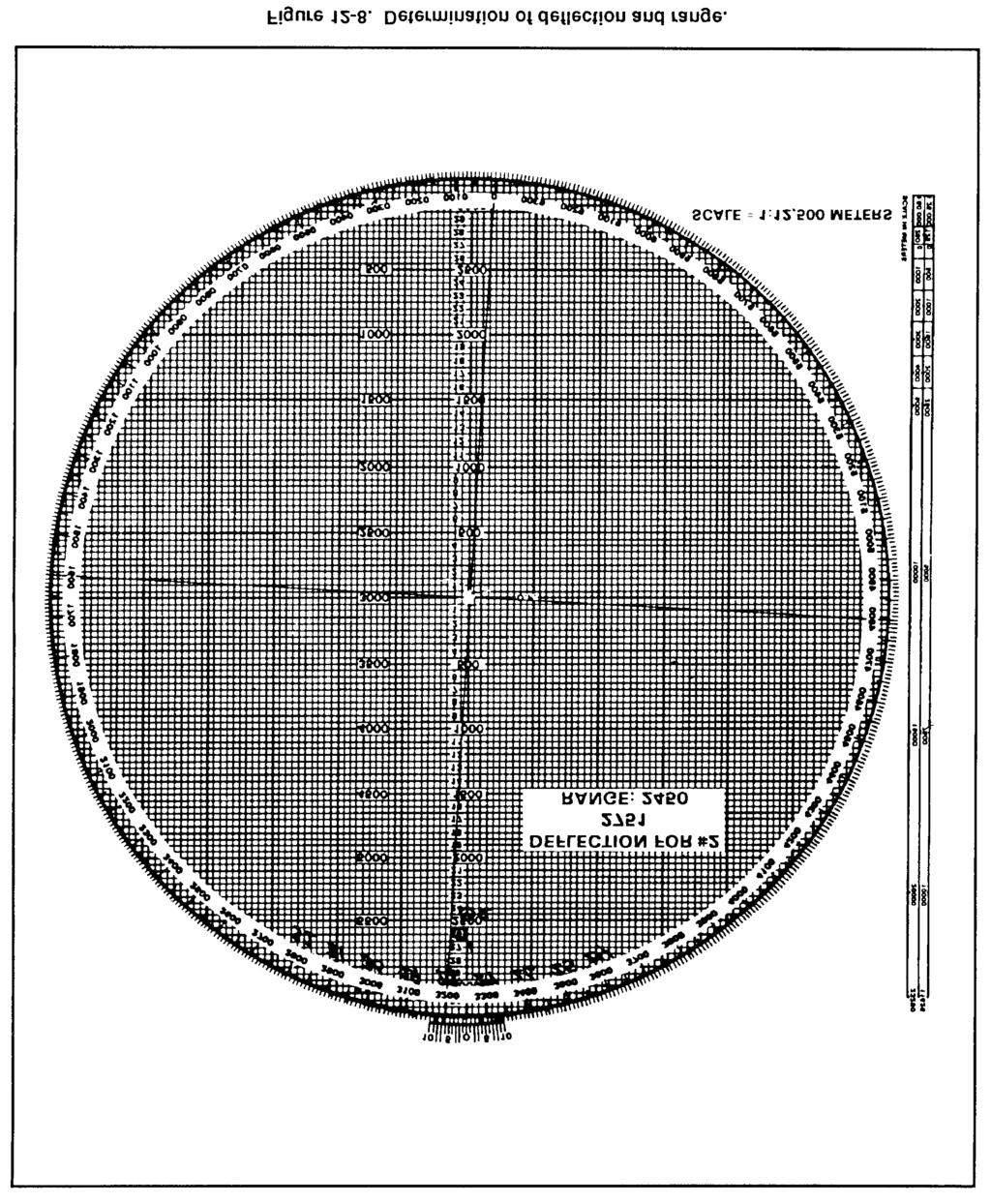
143 12-7
144 12-8
145 (c) Plot the mortar position 500 meters left or right of the vertical centerline (Figure 12-11). (2) Once these actions have been taken, ensure that the azimuth disk is still indexed on the gun target azimuth. Then, from the mortar position, plot the first round at the 12-9
146 range determined using the parallel-line method of plotting (Figure 12-12). Determine the mounting azimuth and referred deflection the same way as with the pivot-point method. (3) To determine the firing data to send to the mortar, align the mortar position below the target being engaged using the parallel-line method of plotting. Then read the deflection using the azimuth disk and vernier scale and measure the range between the mortars and target. To align the mortar position and target, since the mortar position is being plotted away from the pivot point, use the parallel-line method of plotting. With 12-10
147 the mortar position and target plotted, rotate the disk until the mortar position and the target are an equal distance from, or on, the same vertical line (Figure 12-13). NOTE: All directions are read from bottom to top. (4) Now determine ranges differently than with the mortar position plotted at the pivot point. Count each of the 50-meter squares from the mortar position to the target or place the edge of the computer s record alongside the two plots on the plotting board (mortar and target). Then make a tick mark on the edge of the computer s record at 12-11

148 Downloaded from each plot. Using the alternate range scale to the left of the pivot point, lay the computer s record along this scale with the mortar tick mark at 0 and read the range (Figure 12-14)
149 (5) To update the board after the EOM is given or to engage other targets, use the same method as with the pivot-point method. NOTE: When operating the M16 plotting board as an observed firing chart (pivot-point or below-pivot-point methods), no correction factors are applied to the data. c. Mortars Plotted at Pivot Point. With the pivot pin inserted in the pivot point of the plotting board, the computer can use the range scale arm the same as with the range arm to determine deflections and range to both the initial and subsequent rounds. (1) Determine the range and direction to the center of the sector from a map or by visual observation. Round off the azimuth to the initial round or direction of fire (DOF) to the nearest 50 mils to determine a mounting azimuth, and superimpose a deflection scale on the azimuth disk. (2) Make the initial plot by indexing the DOF (or initial azimuth) to the initial round at the index mark. This may be different from the mounting azimuth because of the round-off rule. Use the scale on the vertical centerline to make the initial plot at the correct range. (3) When the FO calls in a target direction (the OT azimuth), index the azimuth disk on the M16/M19 plotting board at the OT azimuth. It remains indexed on that azimuth until the mission is completed. Plot corrections from the FO IAW procedures. Once a correction has been plotted, rotate the range arm until the right edge of the range arm is over the new plot. Determine the range to the nearest 25 meters, and read the deflection to the nearest mil using the vernier scale. (4) Plot additional corrections, and use the range scale arm to determine range and deflection. Once the azimuth disk is indexed on the OT azimuth, the disk does not have to be rotated to determine ranges or deflections. d. Mortars Plotted Below Pivot Point. With the pivot pin inserted in the pivot point, the computer can use the left edge of the range scale arm to plot the initial round. The mounting azimuth and azimuth to the initial round are determined as for mortars plotted at pivot point. The computer indexes the azimuth disk on the DOF and aligns the right edge of the range scale arm on the vertical centerline. Next j he makes a small plot at the zero range on the left edge of the range scale arm. Then, still using the left edge, he makes a small plot at the range for the initial round. The mortar position plot must be marked with a hollow cross to further identify its position. Once the initial round is fired, the range scale arm is removed, and the left edge is used as a range scale. e. Care and Cleaning of Plotting Boards. Plotting boards must be handled with care to prevent bending, scratching, or chipping. They must be kept away from excessive heat or prolonged exposure to the sun, which may cause them to warp. When storing a board, it is placed in its carrying case, base down, on a horizontal surface. It is not placed on edge or have other equipment stored on it. The plotting board can normally be cleaned with a nongritty (art gum) eraser. If the board is excessively dirty, a damp cloth is used. The contact surface of the disk and base are cleaned often. The disk is removed by pushing a blunt instrument through the pivot point hole from the back of the base
150 12-2. MODIFIED-OBSERVED FIRING CHART The modified-observed firing chart can be constructed on the M16 plotting board. It is constructed when the mortar position or target is known to survey accuracy. Three basic items needed to construct the modified observed chart are: a DOF (usually to the center of the platoon area of responsibility), one point (mortar position, target, or reference point) that must be known to surveyed accuracy (eight-digit grid coordinates), and a grid intersection to represent the pivot point. a. Determination of Direction of Fire. The section sergeant usually determines DOF. In most cases, it is to the center of sector. The mortar location can be surveyed by map inspection, terrain inspection, or pacing from a known point on an azimuth, as long as the position of the base gun is known to a valid eight digits, (1) For the 60-mm and 81-mm mortars, the grid intersection representing the pivot point (Figure 12-15) is between 1,500 and 2,000 meters forward of the mortar location. This allows the full range of the mortar to be used. NOTE: When using the M16 plotting board with the 4.2-inch and 120-mm mortars, the grid intersection selected should be 2,000 to 2,500 meters forward of the mortar position. (2) The grid intersection should be outside the area of responsibility. This ensures that the pivot point does not interfere with plotting targets or corrections. The grid 12-14

151 intersection is also as close as possible to the area of responsibility. This ensures that as much of the area of responsibility as possible will be on the plotting board. b. Superimposition of Grid System on Plotting Board. Once the grid intersection has been determined, the computer indexes 0 on the azimuth disk. He then drops down 2,000 meters below the pivot point and writes in the north/south indicator on the vertical centerline at the 2,000-meter mark. Next, he goes 2,000 meters to the left of the pivot point on the heavy center horizontal line and writes the east/west indicator. To complete the grid system, the computer writes in the other north/south, east/west grid numbers as though looking at a map. By numbering every other heavy dark line (two large squares) on the plotting board, he retains a scale of 1:12,500 on the board (Figure 12-16)
 Ensure that the azimuth disk is indexed at 0. (2) Read like a map: RIGHT and UP.")
152 Downloaded from c. Plotting of Mortar Position. Now that a grid system is on the board, the computer can plot any grid coordinates. To do this, he must (1) Ensure that the azimuth disk is indexed at 0. (2) Read like a map: RIGHT and UP. (3) Remember that the scale is 1:12,500 (each small square is 50 meters by 50 meters) (Figure 12-17). To superimpose the deflection scale, the computer writes the referred deflection on the board the same way as with the observed chart. Firing data are determined by using the parallel-line method of plotting

 Index the DOF. (2) Drop below the pivot point on the vertical centerline 2,000 to 2,500 meters.")
153 d. Field-Expedient Method for Construction. If the grid coordinates of the mortar position are known but a map is not available for determining the grid intersection to represent the pivot point, the computer can construct the modified-observed firing chart by using the following procedures: (1) Index the DOF. (2) Drop below the pivot point on the vertical centerline 2,000 to 2,500 meters. (3) Go 500 to l,000 meters left or right of the vertical centerline and make a plot (Figure 12-18)
154 (4) Rotate the azimuth disk and index "0." (5) Determine the l,000-meter grid that contaim the mortars (Figure l2-l9). The first, second, fifth, and sixth numbers of the mortar grid give the 1,000-meter grid square. (6) Superimpose the grid system. (7) Replot the mortar location to the surveyed grid

 and two targets have been fired on (Figure 12-20).")
155 12-3. TRANSFER OF TARGETS Transfer is the process of transferring a target from the observed chart to the modified-observed chart, or from the modified-observed chart to the surveyed chart, as more information becomes available. This occurs since the targets transferred are known points to the FO and FDC, and these points may be used in future missions. Transfer is always done using chart data (deflection and range to the final plot). EXAMPLE Assume that the mortar section is at grid (six digits: observed chart) and two targets have been fired on (Figure 12-20). The platoon leader determines that the eight-digit grid to the mortar position is (modified-observed chart) and designates the grid intersection to represent the pivot point. The computer constructs the chart and transfers the targets from the observed chart (Figure 12-21, page 12-20)
156 NOTE: No firing corrections are used with the observed chart. Once transferred to the modified-observed chart, the altitude of the target is assumed to be the same as that of the mortar position. a. Target Plotting. After transfer, through coordination with the FO, an RP or target may be identified to valid eight-digit coordinates. The plotting board is then reconstructed as a surveyed chart. When the situation permits, a registration mission should be conducted on the point for which the valid eight-digit coordinates were determined. Then firing corrections are computed
157 (1) When transferring targets from one type of chart to another, remember that the target plots on the observed chart are plotted at the data it takes to hit the target. This is not always the locations of the targets. (2) The same holds true for the modified-observed chart, except that with some targets, altitude correction (VI) may have been used. When replotting the target at the end of the mission, strip this altitude correction from the command range and plot the target using this range. Using this procedure gives a more accurate picture of the exact location of the target than the observed chart; however, it is not always the actual location of the target. b. Plotting of Previously Fired Targets. At the completion of the surveyed registration mission and the computation of the firing corrections, previously fired targets plotted on the plotting board must be forward plotted. Since the surveyed chart is the most accurate chart to use, all information on it should be the most accurate possible. EXAMPLE When targets AL0010 and AL0011 (Table 12-1) were fired before the surveyed registration, the data and the plots included all firing corrections, even though they may have been unknown at the time of firing. To forward plot these targets, the computer strips the firing correction from the range and deflection to plot them at their actual location. NOTE: To strip out the corrections, the signs must be reversed DEFLECTION CONVERSION TABLE When an adjustment is made to a sheaf, such as after the completion of the registration, the sheaf is paralleled or converged if engaging a point-type target, or opened when engaging a wider target. In these situations, the computer must determine the new data and convert the deviation corrections required into mils. He can use the deflection conversion table (Figure 12-22, page 12-22) or the mil-relation formula


158 a. To use the DCT, first round off the range at which the section is firing to the nearest 100 meters. This is required because the ranges on the table are divided into 100-meter increments. Next, go down the range column to find the range. The deflection is in meters across the top of the card. b. Using the number of meters the FO requested to move the strike of the round, find that number of meters and go straight down that column until itintersects with the range. That number is the number of mils that would have to be applied to the mortar sight to move the strike of the round the required meters. If the range is greater than 4,000 meters, divide the range and mil correction by two
159 EXAMPLE The mortar section has completed a registration mission and is prepared to adjust the sheaf. The final adjusted range for the RP is 2,750 meters. The No. 1 and No. 3 mortars fire one round each. The FO sends the following corrections: NUMBER 3, R30; NUMBER 1, L20; END OF MISSION, SHEAF ADJUSTED. Any corrections of 50 meters or more must be refired. For this example, the last deflection fired from No. 1 and No. 3 was 2931 mils. Using the DCT, round off the range to the nearest 100 meters (2,800). Find 2,800 meters in the range column and, using the FO s corrections, find 30 and 20 in the deflection-in-meters column. Go across and down those columns to where they intersect. The table shows that the requirements are 11 mils for 30 meters and 7 mils for 20 meters. Using this information, use the previous deflection fired, which was 2931 mils. Since the FO s correction for the No. 3 mortar was R30, which equals R11 mils (using the LARS rule), subtract 11 mils from 2931 mils. This gives a new deflection of 2920 mils. The correction for No. 1 mortar was L20, which equals L7 mils. Using the LARS rule for deflection, add 7 mils to 2931, which gives a new deflection of 2938 mils. If there is no deflection conversion table available, use the mil-relation formula (W/R x M) to convert the corrections from meters to mils. To use the formula for the same FO s corrections of R30 and L20 used in the example cited, cover the item needed (in this case M [mils]). The remainder of the formula states: divide W (width in meters) by R (range in thousandths). W/R = 20/2.8 = M W/R = 30/2.8 = M These are exactly the same figures determined by using the DCT GRID MISSION For an observed chart, the grid coordinates of the target must be plotted on the map, and a direction and distance determined from the mortar location to the target. For modified and surveyed charts, index 0 and plot the target using the grid coordinates. NOTE: Corrections for VI can be used on the modified and surveyed charts SHIFT MISSION For an observed chart, the known point must be plotted on the firing chart. This may be a fired-in target or a mark-center-of-sector round. The OT azimuth is indexed, and 12-23
160 the correction applied is sent in the call for fire. For modified and surveyed charts, the same procedure is used as for the observed chart POLAR MISSION The FO s location must be plotted on the plotting board before a polar mission can be fired. For an observed chart, the location can be plotted in three ways: by resection, by direction and distance, or by range and azimuth from a known point. a. Resection (Figure 12-23). Plot two known points on the plotting board. Then index the azimuths the FO sends from these two points, and draw lines from the known points toward the bottom of the board. The intersection of these lines is the FO s location

161 b. Direction and Distance (Figure 12-24). The FO sends the computer the grid to the FO position. The computer then plots the grid on the map, determines the direction and distance from the mortar position to that grid, transfers the direction and distance to the plotting board, and plots the FO s location. c. Range and azimuth from a known point. The FO must send the range from the known point and the azimuth on which that point is seen. Once that is known, the computer can index the azimuth, drop below the known point the range given, and plot the FO s location (Figure 12-25, page 12-26). For modified and surveyed charts, the 12-25
162 FO s location can be plotted if the grid of the FO is known, by indexing "0" and plotting the FO grid. If the grid is not known, then the computer can use resection, direction and distance, or range and azimuth from a known point
163 CHAPTER 13 TYPES OF MISSIONS Certain missions require that special procedures be applied to effectively engage targets; therefore, these missions should not be fired on the observed chart. Area tarets have width or depth or both, requiring the mortar section to use either searching or traversing fire, or a combination of these TRAVERSING FIRE Traversing fire is used when the target has more width than a section firing a parallel sheaf can engage. Each mortar of the section covers part of the total target area and traverses across that area. The M16/M19 plotting board can be constructed as any one of the three firing charts. Table 13-1 lists the data used to setup the plotting board for traversing fire. a. Upon receiving the call for fire, the section sergeant determines from the size and description of the target that traversing fire must be used to cover the target. (To effectively engage a target using traversing fire, the section sergeant ensures the attitude of the target is within 100 mils of the attitude of the firing section.) The section sergeant then completes the FDC order (Figure 13-1, page 13-2). b. The three or four mortars are plotted separately on the M16/M19 plotting board, using the attitude of the section. During the mission, the computer ensures that the correct plots are used to determine data required for example, during the adjustment, the impact point is aligned with the No. 2 mortar plot. Using the information in the call for fire, the FDC order, and the observer corrections, the computer computes the data to adjust the No. 2 mortar onto the center mass of the target. After the adjustment is complete (Figure 13-2, page 13-3), the computer must complete the following procedure: (1) Plot the 250-meter length of the target on the plotting board using the attitude of the target. (2) Divide the target into segments. (3) Determine the number of rounds for each segment. (4) Determine the mil width of one segment. (5) Determine the number of turns required to cover one segment. (6) Determine the number of turns between rounds. 13-1

164 13-2
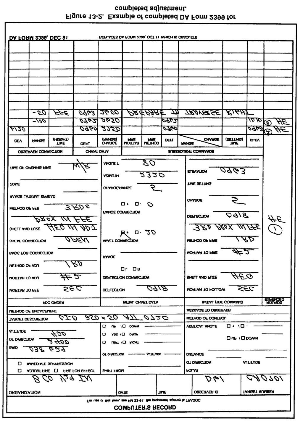
165 . 13-3

166 c. To plot the target on the plotting board, the computer rotates the azimuth disc until the target attitude (taken from the call for fire) is indexed. The computer erases all the plots except the last plot. After ensuring that the attitude is indexed, the computer divides the total target area into segments. These plots represent the starting points for each mortar. The area between the plots is the area each mortar must cover with fire (Figure 13-3). d. The target is now divided into three segments. Once the remaining data for one segment have been determined, the data will apply to all three mortars. Since each segment of the target is 75 meters, if the computer determines the mil width of one segment, the other two will be the same. The computer can use one of two methods to determine the number of mils for one segment. 13-4
.")
167 (1) In the first method, the computer knows the deflection that was used to hit the No. 3 point. By aligning the No. 2 plot and No. 3 mortar, the computer can determine the deflection to fire to hit the start point for the No. 2 mortar (Figure 13-4). Subtracting these two numbers determines the mil width of the segment: Number 3 plot deflection Number 2 plot deflection Mil width of segment 2993 mils 2942 mils 51 mils (2) The second method uses the DCT to determine the mil width of one segment. The computer enters the DCT at the final chart range that is rounded off to the nearest 100 meters. He goes across the deflection-in-meters line to the closest meters (75) to cover the segment. The point at which the range line and the 13-5
168 deflection line meet is the number of mils that will cover the segment. Each turn of the traversing handwheel is about 10 mils. By dividing the mil width of each segment (29) by 10, the computer obtains the total number of turns to cover the segment (round off to the nearest whole turn): e. To compute the number of turns to take between rounds, the computer must know how many rounds will be fired for each segment. This information is given in the FDC order (3 rounds). To determine the turns between rounds, the computer divides the total turns by the interval between rounds (there will always be one less interval than the number of rounds: 3 rounds = 2 intervals). Turns between rounds are rounded to the nearest half turn. The number of rounds to fire is based on the rule: four rounds per 100 meters of target width, or one round per 30 meters. f. At this point, the computer must determine the deflection and range for each mortar by aligning each mortar with its start point, completing the subsequent command, and issuing it to the mortar section. If there is a range change of 25 meters or more, the mortar will receive its own elevation. g. Upon completion of the adjustment phase of the mission, the section is given the command PREPARE TO TRAVERSE RIGHT (LEFT). The gunners then traverse the mortars all the way in the direction opposite to that given, back off two turns, and await further instructions (Figure 13-5) SEARCHING AND ZONE FIRE An area target having more depth than 50 meters can be covered by mortars by either elevating or depressing the barrel during the FFE. An area up to 50 meters can be covered by a section three mortars firing four rounds on the same elevation and deflection due to range and deflection dispersion. In the call for fire, the FO sends the size of the target and attitude since it is more area to cover than a section firing a parallel sheaf can engage. The FO gives the width and then depth of the attitude of the target. Attitude is the direction (azimuth) through the long axis of the target. 13-6
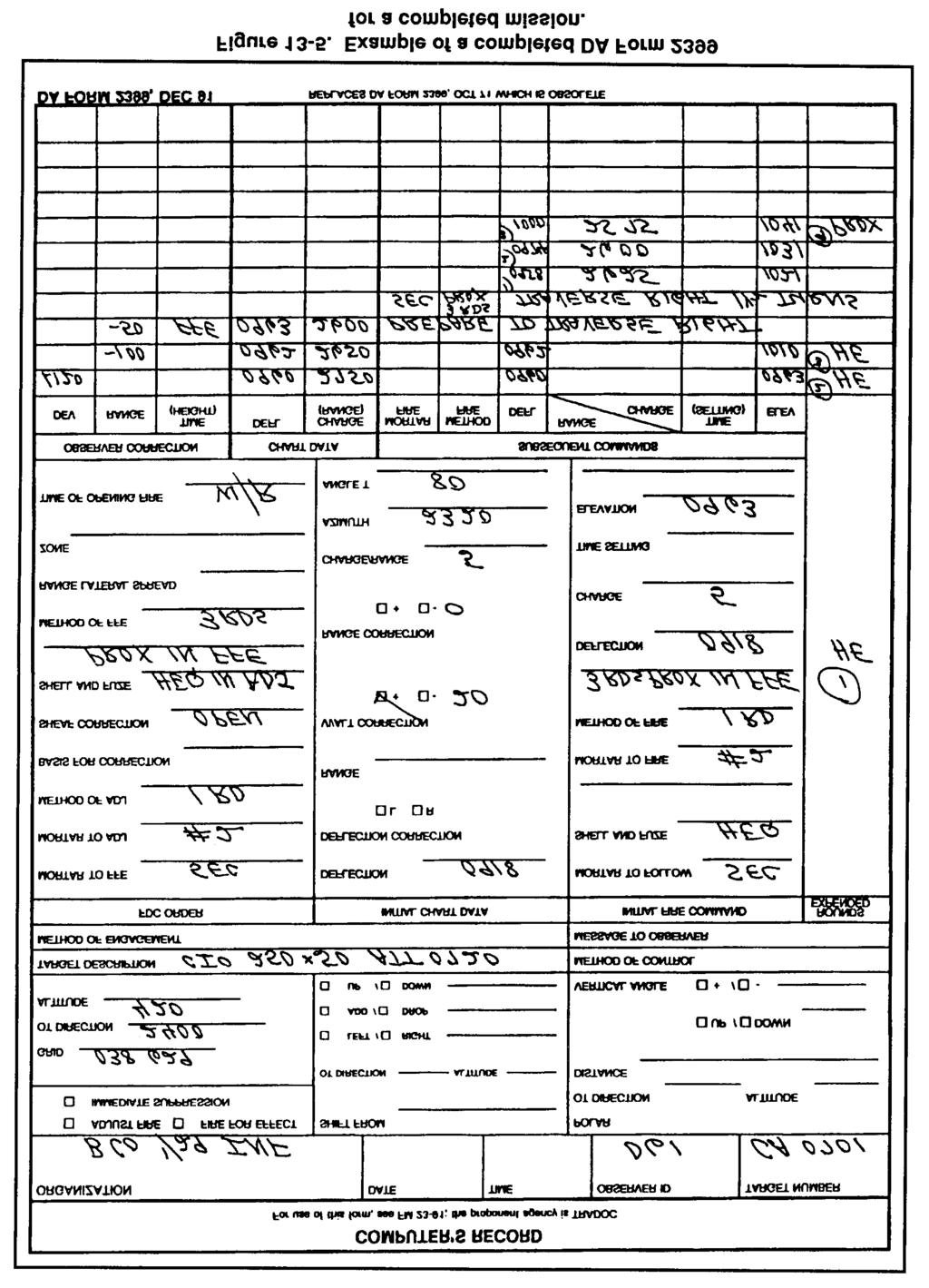
169 13-7
170 a. Searching Fire. For the mortar section to effectively engage a target using only searching fire, the attitude of the target cannot be more than 100 mils difference from the attitude of the gun section. If the difference is more than 100 mils, the target should be engaged using a combination of searching and traversing fire, or traversing fire only. When the section is firing a searching mission, the adjustment phase of the mission is the same as a regular mission using the base mortar (No. 2) as the adjusting mortar. The base mortar is adjusted to center mass of the target. (1) Upon completion of the adjustment phase of the mission, the computer must compute the data to cover the target with fire. He must determine the number of rounds to cover the target, the turns required to cover the target, and the turns between rounds. (2) With the target area given in the call for fire, the computer can determine the number of rounds needed to cover the target. When firing on a target using traversing or searching fire, the computer uses 4 rounds for every 100 meters of either target width or depth, or 1 round for every 30 meters. The computer must always consider the number of rounds on hand and the resupply rate when determining the number of rounds to fire. EXAMPLE Assume that the depth of the target is 350 meters. Multiply the even 100 s by 4: = 12. For the remainder of the target depth (50 meters), one round covers 30 meters, which would add one more round: = 13 rounds. At this point, 20 meters of target is left. To cover the 20 meters, add one more round. (3) When determining the number of turns needed to cover the target, the computer can use one of two methods. If the computer is using the unabridged firing table (all escept for FT 4.2-K-2), the number of turns in elevation required for a 100-meter change in range is given in column 4 of Table D (basic data). EXAMPLE Assume that the target is 350 meters in depth, the range to the target center of mass is 2,125 meters (always use chart range), and the firing charge is 4. To determine the turns, determine the range to the center of mass of the target (2,125), enter the firing table at charge 4, range 2,125, and go across to column 4. Four turns are needed to cover 100 meters. Multiply 4 by 3.5 (range in hundreds): 4 x 3.5 = 14 turns to cover the target. The mortars are adjusted to center of mass. To obtain the range to the far edge (search up), add half the target area to the range to the center of mass. EXAMPLE The range to the center is 2,125 meters; target area is 100 meters by 350 meters; half of target depth is 350 divided by 2 = 175 meters; and the range to the far end is 2,300 meters. To search down, start at the near edge and subtract half the target depth from target center. 13-8
171 (4) Applying the second method, the computer must determine the mil length of the target by using the firing tables. He uses the elevation for the far end of the target (adjusting point) and the elevation to hit the near end of the target: Range to adjusting point 2,300 meters Elevation 974 mils Range to near end 1,950 meters Elevation 1128 mils By subtracting the two elevations, the computer has the mil length of the target: Length of target 1128 mils 974 mils 154 mils (5) Each turn of the elevating crank is 10 mils. Dividing the mil length of the target (154 mils) by 10 gives the computer the total turns to cover the target: NOTE: Table D (basic data) in all FTs (except for FT 4.2-K-2), column 4, gives the number of turns per 100 meters difference in range. These data may be used to determine the total turns to cover the target. (6) To compute the number of turns to take between rounds, the computer must know how may rounds each mortar will fire. The computer computes this information or finds it in the FDC order (14 rounds). To determine the turns between rounds, he divides the total turns by the intervals between rounds (there will always be one less interval than the number of rounds: 14 rounds = 13 intervals). (7) The computer rounds turns to the nearest half turn. The number of rounds to fire is based on the rule: five rounds per 100 meters of target depth, or one round per 20 meters. At this point, the computer has all the information needed to complete the subsequent command. The command can then be issued to the mortars (Figure 13-6, page 13-10). 13-9


172 13-10
173 (8) The only difference between a search UP mission and a search DOWN mission is the starting point. Normally, a search mission is fired by searching UP. This allows the FO to better observe the effect of the rounds on target as the rounds walk toward him (Figure 13-7). b. Zone Fire. The 4.2-inch mortar does not fire a search mission the same as the 120-mm, 81-mm, 60-mm mortars. It does not have the same elevating characteristics as the other mortars; therefore, the 4.2-inch mortar uses zone fire when targets have more depth than a platoon/section can cover when firing a standard sheaf. The 4.2-inch mortar platoon/section usually fires two standard zones: a 100-meter zone (three rounds for each mortar) for a platoon-size target, and a 200-meter zone (five rounds for each mortar) for a company-size target. Note: A larger zone can be covered by firing one round for every 50-meter increase in the target area. (1) Establishing the 100-meter zone. Once FO gives the FFE, the computer proceeds as follows: (a) Firing without extension (M329A1). Add and subtract 3/8 charge from the base command charge. (The base command charge is the command charge in the FFE 13-11
174 center mass of target.) This gives each mortar three rounds with a different charge on each to cover the 100-meter zone (Figure 13-8). (b) Firing with extension (M329A1). Add and subtract 4/8 charge from the base command charge and use three rounds for each mortar. Note: A 3/8 charge correction to any charge without extension moves the round about 50 meters at any elevation used. A 4/8 charge correction to any charge with extension moves the round about 50 meters at any elevation used. (c) Firing with M329A2. Add and subtract 2/8 charge from the base command charge. (d) Firing the 100-meter zone. Once the mortars are up (rounds set for proper charges) and the fire command is given, fix the rounds in any sequence for example, No. 1 fires long, short, center mass; No. 2 fires center mass, short, long. (2) Establishing the 200-meter zone. Once the FFE has been given by the FO, the computer proceeds as follows: (a) Firing without extension. Add and subtract 3/8 charge from the base command charge for the rounds on either side of the base round and 6/8 charge for the long and short round (Figure 13-9). (b) Firing with extension. Add and subtract 4/8 charge from the base command charge for the rounds on either side of the base round and a whole charge for the long and short rounds
175 (c) Firing With M329A2. Add and subtract 2/8 charge from the base command charge. (d) Firing the 200-meter zone. Fire the rounds in any sequence ILLUMINATION Illumination assists friendly forces with light for night operations. The M16/M19 can be setup for illumination as any one of the three types of firing charts. Determining firing data is the same as with any type of mission, only now the FDC uses one of the flank mortars to adjust the illumination, leaving the base mortar (No. 2) ready to adjust HE. The FO enters corrections for the illumination rounds in range deviation not less than 200-meter corrections, and corrections for height (up/down) not less than 50-meter corrections. a. Observers. Observers who are to adjust illumination should be informed when the 81-mm mortars are firing M301A3 illumination rounds. The M301A3 has an HOB of 600 meters, while the M301A1 and M310A2 rounds have 400-meter HOBs. There is a difference in adjustment procedure. The M301A1 and M301A2 rounds are adjusted to a ground-level burnout; the M301A3 round should have a burnout 150 to 200 meters above ground. This procedure is based on the fact that all three of the rounds fall at a rate of 6 mps (Table 13-2, page 13-14). b. Corrections. The ranges in the firing tables are in 50-meter increments. (Rule: Always round up, such as range 2,525 meters = 2,550 meters, to enter Part II of the firing tables.) Corrections to the HOB are obtained in columns 4 and 5. These corrections are used to move the roundup or down in relation to the HOB line (Fig 13-10, page 13-14)


176 13-14
177 EXAMPLE Chart range to the first round fired: 2,525 meters = 2,550 meters to enter the firing table (FT 81-A1-3). Optimum charge to use: charge 8 Basic data, columns 1 (Range to Burst), 2 (Elevation) and 3 (Fuze Setting) to give the basic HOB for 600 meters above the mortar position: Range to Burst = 2,550 meters Elevation = 1107 mils Fuze setting = 31.0 c. Adjustments. The round is fired and the FO sends: ADD TWO ZERO ZERO (200), UP ONE ZERO ZERO (100). The computed range is now 2,725 = 2,750 (Figure 13-11, page 13-17). The basic data only give an HOB of 600 meters, but the FO requested an UP 100, meaning that the round needs more height. To compute this change, the computer must determine where this round will be in relation to the HOB line: HOB = 600 meters; UP 100 is two increments above the HOB line. Once the number of increments has been determined, the computer goes to column 4 (change in elevation for 50-meter increase in HOB) and column 5 (changes in fuze setting for 50-meter increase in HOB), and multiplies the increments times the correction factors given in these columns. EXAMPLE Range to burst 2,750 meters, + 2 increments Column 4 = 14 X 2 increments (100 mils above HOB) = -28 mils Column 5 = X 2 increments (100 mils above HOB) = -1.4 seconds (1) Once the corrections have been determined, apply those to the basic data (columns 2 and 3) to obtain the firing data for the next round. EXAMPLE Basic data: column 2 = 1034 (600 meters HOB) -28 mils (correction) 1006 (elevation needed to fire) column 3 = 29.5 (600 meters HOB) -1.4 (correction) 28.1 (time set needed to fire) (2) Assume that the second round is fired and the FO sends: DOWN FIFTY (50). Note that a range change was not sent, but an HOB correction was sent. Again, determine the relation to the HOB line and apply the correction factors to the basic data to obtain the firing data
178 EXAMPLE Range to burst 2,750 meters, charge 8, down 50. The computer is now working with one increment above the HOB line. Increments (relationship to HOB, 600 meters) 1 X -14 (column 4) = X -0.7 (column 5) = -0.7 New data: 1034 mils (basic data) -14 = 1020 mils elevation 29.5 (basic data) 0.7 = 28.8 fuze setting. (3) When the correction is below the HOB line, use the opposite sign of the sign found in columns 4 and 5 to obtain the same HOB. To compute the correction, assume that the chart range to burst is 1,550 meters and the optimum charge is 6. The first round is fired at an elevation of 1260 mils with a fuze setting of (4) The FO sends: DROP TWO ZERO ZERO (200), DOWN ONE FIVE ZERO (150). Assume that the new range is 1,325 meters ( = 1,350), and the optimum charge is 5. The procedure for determining the increments is the same as with the last example: 600-meter basic HOB, down 150 = 3 increments below the HOB line. (5) Determining the correcting factors is the same as before, except that when computing below the HOB line, reverse the signs since columns 4 and 5 are setup for increases in HOB. 3 X 8 (column 4) = 24 mils = +24 mils 3 X -0.6 (column 5) = 1.8 sec = sec Determining new firing data is the same as before. Basic data: 1245 mils (column 2) +24 mils = 1269 mils elevation 25.9 (column 3) sec = 27.7 fuze setting (6) Assume that the second round is fired and the FO sends: DROP TWO ZERO ZERO (-200), and the new range is 1,150 meters. Note that a range change is given but not an HOB correction. When only a range change is sent, only the increments below the HOB line for the old range must be applied to the new range to keep the HOB correct. To determine the data, apply the steps as before: Increments below HOB = 3 Correcting factors: 3 X -5 = -15 = +15 (sign reversed) 3 x -0.5 = -1.5 = +1.5 (sign reversed) New data: 1309 mils + 15 mils = 1,324 mils elevation = 28.1 fuze setting 13-16

179 , 13-17
180 CHAPTER 14 SPECIAL CONSIDERATIONS This chapter discusses the special procedures applied to some missions to effectively engage targets REGISTRATION AND SHEAF ADJUSTMENT Firing the registration is the first mission that will be completed if time and the tactical situation permit. a. Firing Coordinated and Noncoordinated Missions. Two types of registration missions are fired on the surveyed chart: coordinated and noncoordinated. (1) Firing coordinated missions. The FDC and FO coordinate the location of the RP before the FO joins the unit to support it. Once the FO is in position, the FDC sends a message telling the FO to prepare to register RP 1. The FO sends the OT direction to the RP. (2) Firing noncoordinated missions. The FO, upon joining the unit to support it, checks the area of responsibility and selects a point to be used as the RP. This point must be identifiable both on the ground and on the map to allow a valid eight-digit grid to be determined. The FO then sends the call for fire to register the RP. b. Constructing Surveyed Firing Chart. The surveyed firing chart is the most accurate chart that can be constructed. It can be used to determine all the correcting factors that are needed to fire more first-round FFE missions than the other firing charts. Three items must be known to construct the surveyed chart: a grid intersection to represent the pivot point, a surveyed mortar position, and a surveyed registration point. (The construction of the surveyed chart is similar to the modified-observed chart.) (1) To obtain the DOF after constructing the chart, align the mortar position with the Rp. Determine the DOF to the nearest mil. (2) To determine the mounting azimuth, round off the DOF to the nearest 50 mils. (3) To superimpose the deflection scale, the referred deflection is received from the section sergeant. Then, construct the deflection scale in the same manner as for the modified-observed chart. NOTE: The procedure to obtain the firing data is the same as with all firing charts. (4) Determine correction factors after the registration has been completed. Apply these factors to all other targets within the transfer limits of the RP. c. Obtaining Firing Data. Obtaining the firing data is the same as with any mission, except that the FO continues to adjust until a 50-meter bracket is split and 14-1
181 the last fired round is within 25 meters of the target (Figure 14-1). Refinement corrections are sent to the FDC and the mission is ended. Table 14-1 provides information to be used insetting up the plotting boards to fire a surveyed registration. d. Adjusting the Sheaf. The purpose of adjusting the sheaf is to get all mortars firing parallel. The mortars are positioned with gun No. 1 through 4 for the 81-mm and the 120-mm platoons, No. 1 through 6 for the 4.2-inch (when employed as a platoon), or No. 1 through 3 for the 4.2-inch (when employed as a section) from right to left as seen from behind the guns. There is normally a 10-second interval between rounds. The FO needs that time to observe the impact of the rounds and to determine corrections. If the corrections are 50 meters or more (deviation left/right only), the mortar must be refired. The corrections can be plotted on the board, or the DCT (Figure 14-2) can be used to determine the number of mils to add or subtract from the base mortar deflection. EXAMPLE The sheaf of a 81-mm platoon is being adjusted, No. 2 mortar conducted the registration. The FDC has requested to prepare to adjust the sheaf. The FO requests section right. The entire platoon then fires, in order, starting at the left (No. 4, 3, 1) with 10-second intervals between rounds. The mortar that was used to register (No. 2) will not fire. The sheaf is adjusted perpendicular to the gun-target line. The observer notes where each round lands and sends back deviation corrections in meters; range corrections are ignored if less than 50 meters. If a deviation correction is 50 meters or more, it must be refired. Corrections to be refired should always be transmitted first by the FO. 14-2
 and with the lateral spread between rounds equal to the bursting")
182 If angle T is greater than 500 mils, each piece is adjusted onto the registration point, and the FDC computes the data for the sheaf. In adjusting the sheaf, all rounds must be adjusted on line at about the same range (within 50 meters) and with the lateral spread between rounds equal to the bursting diameter of the ammunition used. 14-3
183 The spottings from the FO are No. 4, right 20, No. 3, left 60, and No. 1, left 30 (Figure 14-3). The FO sends the corrections to the FDC; No. 3, right 60 (since it needs to be refired), No. 4, left 20 No. 4 is adjusted, and No. 1, right 30 No. 1 is adjusted. The No. 3 mortar is now fired, and the round impacts 10 meters right of the desired burst point. The FO then sends: No. 3, left 10, No. 3 is adjusted, sheaf is adjusted, end of mission. e. Obtaining Firing Corrections Using the Deflection Conversion Table. The computer enters the DCT at the initial chart range rounded to the nearest 100 meters: 3050 = (Remember, the RP is at a surveyed grid, and it has not moved.) Using the deflection in meters line at the top of the table, the computer finds the meters needed to correct the sheaf. Where the range line and the correction line meet is the number of mils needed to apply. He applies the mils to the base deflection. (When working with deflections, use the LARS rule.) Once the FO has given EOM, Sheaf adjusted, the section is given, Section, refer deflection two eight zero one (2801), realign aiming posts, (2801 was the base mortar s hit deflection). This procedure allows all mortars to befired with the same data, and the resulting sheaf will be parallel. f. Determining Firing Corrections. Once registration is completed, the firing corrections (range correction factor and deflection correction) are determined for use within the transfer limits of the RP (Figure 14-4). The computer applies correction factors to correct for nonstandard conditions (weather and equipment wear) affecting the round. Range correction is the number of meters to be added to or subtracted from the chart range to hit the target because of the nonstandard conditions. As the registration mission is fired and completed, the rounds on the plotting board may not be plotted at the point where the RP was plotted, Because of wind and weather, the rounds may have to be fired at a greater or lesser range and to the right or left of the target to hit it. As shown in Figure 14-5, the initial chart range to the RP was 3,050 meters; the final adjusted chart range (range used to hit the RP) was 3,
184 g. Determining Range Difference. The computer compares the initial chart range and the final adjusted chart range and subtracts the smaller from the larger. This gives the range difference. If the initial chart range is larger than the final adjusted chart range, then the range correction is a minus ( ). If it is smaller, then the range correction is a plus (+). EXAMPLE Initial chart range smaller: 3,050; final adjusted chart range: 3,200 Then, 3,200-3,050 = meters. Initial chart range larger: 3,200; final adjusted chart range: 3,050 Then 3,200-3,050 = 150 meters. (1) Range correction factor. The RCF is the number of meters per thousand to be added to or subtracted from the chart range to hit a target within the transfer limits. Continuing the preceding example, since the ranges to other targets will not be 3,050 (range to RP), the RCF (+150) will not be correct. Therefore, other range corrections must be determined and used for other targets. Once the range difference has been determined, round the initial chart range to the nearest 100 and then express that in thousandths. Initial chart range: 3,050. Round to nearest 100 = 3,100 expressed in thousandths = 3.1. Divide the range in thousandths into the range difference: EXAMPLE Determine to the nearest whole meter and use the sign of the range correction. 14-5
185 (2) Deflection correction. The deflection correction is the number of mils needed to correct the deflection to hit the target since nonstandard conditions again caused the plots on the board to be either left or right of the initial chart deflection (Figure 14-6). Compare the initial chart deflection and the final chart deflection and subtract the smaller from the larger. RULE: Final chart deflection (hit) larger = LEFT deflection correction Final chart deflection (hit) smaller = RIGHT deflection correction. EXAMPLE Hit Larger Hit deflection: 2801 Initial chart deflection: 2790 ( = L11) EXAMPLE Hit Smaller Hit deflection: 2790 Initial chart deflection: 2801 ( = R11) Range and deflection corrections are applied to all other targets within the transfer limits of the RP. h. Firing of a Total Range Correction Mission. The procedure for a mission on the surveyed chart is the same as with the modified-observed chart. However, now the firing corrections are applied to chart data to obtain command data (firing data sent to the mortars). For example, the computer assumes that the board is still setup on the information for the registration mission, and the mission in Figure 14-6 has been received. It is within the transfer limits. 14-6

186 14-7
187 i. Applying Firing Corrections. Once the chart data have been determined, the computer applies the deflection correction by either adding or subtracting the deflection correction to the chart data determined. When working with deflection corrections, the computer uses the LARS rule. The deflection correction must be applied to each chart deflection throughout the mission. EXAMPLE L11 = 2726 (1) Range correction factor. Determine the initial chart range, then round to the nearest hundred and express it in thousandths; for example, 2975 = 3000 =3.0. Multiply the range in thousandths times the RCF and use the sign of the RCF: 3.0 X +48 = This gives the range correction for this target. (2) Total range correction. The total range correction (TRC) is the total correction that must be applied to get the command range to fire the target. TRC is the range correction (RCF x range in thousandths) plus or minus the altitude correction. EXAMPLE Range correction = (altitude correction) = TRC The two factors (RCF and altitude correction) are compared. If one of these factors is a negative, subtract the smaller from the larger. The sign of the larger is used for the TRC. If both factors are negative or positive, then add the two factors to get the TRC. This must be applied to every chart range to obtain command range. To enter the firing tables, the command range is rounded to the nearest 25 meters. j. Firing Reregistration. The FDC must consider weather changes to ensure the accuracy of the firing data (firing corrections) from the surveyed chart. Two methods can be used to do this: reregistration on the RP or MET message. Of those two methods, reregistration is the better because all the unknown (nonstandard) factors are fired out. However, due to countermortar-radar, determining and applying the MET messages may be safer. Choice would be dictated by the tactical situation and the availability of the MET messages. (1) Fire the reregistration at the established RP using only the mortar that originally fired the registration (Figure 14-7). (The FDC assumes that the sheaf is still parallel; therefore, the sheaf should not need adjusting again.) The chart data are the same as with the initial registration. Apply the firing corrections to obtain the command data (Figure 14-8, page 14-10). (A blank reproducible copy of DA Form 2188-R, Data Sheet, is located at the back of this manual.) 14-8


188 14-9


189 14-10
190 (2) The chart deflection plus or minus deflection correction equals command deflection. The chart range plus or minus the range correction plus or minus the altitude correction equals the command range. (3) Carry out the mission the same as with the initial registration. Once the EOM, Registration complete, has been given, determine firing corrections again. (4) In the initial registration, the FDC compared the initial chart range and the final chart range difference. Determining the range difference after the reregistration is the same; however, now determine the final adjusted range. During the reregistration, firing corrections were applied for each round. Now apply those same corrections. (5) Adjusted range is the final range with the correction for altitude correction deleted. EXAMPLE Final command range: 3, 100 meters; altitude correction: -25. Final adjusted range: 3, = 3,125. The altitude correction is added since it was initially subtracted. If the altitude correction had been a plus (+), then it would have been subtracted to obtain the final adjusted range. (6) Once the final adjusted range has been determined, compare the initial chart and the final adjusted range. Subtract the smaller from the larger to determine the RCF. The sign (+/ ) would be determined as with the initial registration. Again, divide the range (initial chart range rounded to the nearest 100 expressed in thousandths) into the new range correction to determine the new RCF. (7) To determine the deflection correction, compare the initial chart deflection and the final command deflection. Subtract the smaller from the larger and determine the sign (L or R) to apply. (8) Apply the new firing corrections to all targets that have been and are fired within the transfer limits. For those targets that are already plotted on the board, apply the new firing corrections and update the target data. (The chart data do not change. The target has not moved; only the weather has changed.) MEAN POINT OF IMPACT REGISTRATION The FDC uses MPI registration during darkness and on featureless terrain to determine firing corrections. Two M2 aiming circles or radar must be used to conduct an MPI registration. (MPI registration can also be used for reregistration.) a. Conduct of an MPI Registration. To fire the MPI registration, the FDC must proceed as follows: (1) Set up the M16/M19 plotting board as a surveyed firing chart (eight-digit grids to the mortar position and RP). (2) Plot the location and altitudes of the two FO points to be used
191 Because the FOs will be sending azimuth readings for the impact points of the rounds, they must see the area of the RP using the M2 aiming circle. (3) Record all data on DA Form 2188-R. To determine each FO s direction to the RP, rotate the azimuth disk until the FO s position is aligned with the RP. Read the azimuth scale to the nearest mil. To determine each FO s vertical angle, compare the altitudes of each FO s location and the RP, and subtract the smaller from the larger. This remainder is the VI, which is used to determine the vertical angle and carries the sign of the larger. Determine the range from each FO s location. Round the range to the nearest 100 and express it in thousandths. Divide the range expressed in thousandths into the VI and determine the product to the nearest whole mil. The sign (+/-) of the vertical angle (VA) is the same as the VI sign (+/ ). EXAMPLE Assume that the VI is 80 for FO 1 and +50 for FO 2. The range for FO 1 is 2,525 meters; for FO 2 it is 3,000 meters. Send the direction and vertical angle to the FOs so they can setup their M2 aiming circles. (4) To determine the firing data, align the mortar position with the RP. Determine the chart data and apply the range correction for altitude between the mortar and target, During the registration, only the range correction for altitude is used. Give the firing command to the base mortar. Three to six rounds will be fired at 10-second to 20-second intervals. The FO uses this interval to give himself time to determine the azimuth readings to each round. If the azimuth for one or more rounds is determined to be 50 or more mils different, then another round may be fired for each erratic round, Six rounds are needed for the most accurate MPI registration, but as few as three rounds give correction data. (5) As the rounds are fired, the FO reads the azimuth to each round and records it. When the last round has been fired, he sends the data recorded to the FDC. Once the rounds have been fired and the readings recorded in the FDC, plot the MPI as follows: (a) Determine the total by adding all the readings from each FO. (b) Divide the total by the number of readings to determine the average of the readings to the nearest mil
192 EXAMPLE FO 1 FO TOTAL mils 2412 mils NOTE: FO may send the average azimuth. (c) Once the average azimuth for each FO has been determined, index the average azimuth and draw a line from each FO position toward the top of the board; where the lines intersect is the MPI. Determine and record the eight-digit grid coordinates and altitude of the MPI. b. Determination of Range Correction Factors. With the MPI and RP on the board and the altitude determined, correction factors to be applied to other targets within the transfer limits of the RP must be determined. Again, because of the effects of interior and exterior ballistics on the round, the MPI may not be plotted in the same location on the plotting board as the surveyed point. Therefore, the corrections to hit that surveyed point must be determined. These corrections are noted on DA Form 5472-R, Computer s Record (MPI) (Figure 14-9, page 14-14). (A blank reproducible copy of DA Form 5472-R is located at the back of this manual.) (1) Range difference. Compare the command range to the MPI point (minus the altitude correction) and the initial chart range to the RP. EXAMPLE Command range MPI = M Alt 500 mils, MPI Alt 450 mils, VI = -50, Alt Corr-25. Adjusted chart range to the MPI = command range 2,650 M + 25 (to delete altitude correction, reverse the sign) = 2,675 adjusted chart range to the MPI. The sign of the range difference is determined by how the move from the MPI to the RP must be made. If the RP range is larger, the difference is a plus (+); if smaller, it is a minus ( )


193 14-14
194 EXAMPLE Initial chart range to the RP is 2,600 meters; adjusted chart range to the MPI is 2,675 meters. 2,675 2,600 = 75 range difference (2) Range correction factor. Once the range difference has been determined, divide it by the chart range to the MPI rounded to the nearest 100 expressed in thousandths and round it to the nearest whole meter. The sign is the same as the range difference. EXAMPLE Range difference 75; chart range to MPI 2,675 meters. Rounded to the nearest 100 = 2,700 meters Expressed in thousandths = 2.7 (3) Deflection correction. Compare the chart deflection of the MPI and the chart deflection of the RP (Figure 14-9, page 14-14) to determine the deflection correction. The sign of the deflection correction will be determined by how the move from the MPI to the RP must be made. RULE: RP deflection is greater than MPI deflection = LEFT deflection correction RP deflection is less than MPI deflection = RIGHT deflection correction EXAMPLE MPI chart deflection = 2810; RP chart deflection = = L20 (correction to apply R20) The application of the correction factors to other targets, within the transfer limit of the RP, is the same as with the other registration corrections, except that the sign of the corrections must be reversed. The only time the corrections will be applied with the signs as determined is when the corrections are being applied to move the strike of the round from the MPI to the RP
195 14-3. VERTICAL INTERVAL CORRECTION FACTORS When the mortar position is known to surveyed accuracy and a map is being used, the computer can work with altitude differences and the correction factor for those altitude differences. As noted earlier, the term used for altitude difference is vertical interval (VI). a. Determination of Vertical Interval. The computer compares the altitude of the mortar position and the altitude of the target being engaged. If the altitude of the target is higher than that of the mortar position, then the VI will be a plus (+); if lower. it will be a minus (-) (Figure 14-10). b. Correction for Vertical Interval. Because of the VI, a range correction must be applied to the chart range to obtain the range to be fired (command). The range correction to apply is half of the VI; it is determined to the nearest whole meter. EXAMPLE VI = 75 meters 1/2 = 38 meters (altitude [range] correction) The altitude (range) correction must be 25 meters or more to be applied. The range correction is then added to or subtracted from the chart range. If the target is higher than the mortar, the computer adds the range correction; if lower, the computer subtracts to get the altitude to be fired (command). The altitude correction is applied to every chart range throughout the mission
196 NOTE: A VI of less than 50 meters is not used when working with the modified-observed chart. c. Determination of Vertical Interval for Different Missions. When there is a difference in altitude between the mortar position and the target, a range correction is made. Since the mortar round has a steep angle of fall, corrections are made only when differences of 50 meters or more in altitude exist. The chart range is corrected by one-half the difference in altitude expressed in meters. The correction is added when the target is above the mortar, and subtracted when the target is below the mortar. Difference in altitude can be determined from contour maps, by estimating, or by measuring the angle of sight, and by using the mil-relation formula. (1) Grid missions. The target is plotted on the map and the altitude determined. If the altitude of the target cannot be determined, then the computer assumes that it is the same as that of the mortars. (2) Shift missions. The target is assumed to be the same altitude as the point being shifted from unless, in the call for fire, the FO sends a vertical shift (up or down). Therefore, that shift is applied to the point being shifted from, and that is the altitude of the new target. (3) Polar missions. The altitude of the target is assumed to be the same as that of the FO s position if no vertical shift is given. If one is given, then the computer applies the shift to the FO s altitude, and that is the altitude of the new target. Once the computer has determined the altitude of the target, then it is possible to determine the VI for the mission and, finally, the altitude correction to apply. Remember, VI is the difference in altitude between the mortars and the target RADAR REGISTRATION Radar registration is another method used by the FDC to obtain firing corrections to apply to the firing data to obtain better accuracy. a. Two types of radar units can be used: AN/PPS-5, which gives direction and distance to impact; and AN/PPS-4, which gives grid of impact. The one used will determine which method the FDC will use during the registration. At the unit level, the AN/PPS-5 will probably be used for the 60-mm and 81-mm mortars; the AN/PPS-4 for the 4.2-inch and 120-mm mortars. NOTE: Registration of the AN/PPS-5 is explained here for the 60-mm and 81-mm mortars. b. The M16/M19 plotting board must be set up as a surveyed firing chart. That is, the mortar position, RP, and radar site must be plotted to surveyed accuracy. The procedure for obtaining firing data is the same as with a regular registration mission. The altitude correction is the only firing correction used. Because this is a polar-type mission, the VI is now obtained as with a polar mission. The firing corrections are obtained in the same manner as with the regular registration mission. c. After the board is set up and the direction and distance from the radar to the target have been determined, the FDC informs the radar operator of this information. The radar operator then orients the radar set using the information and calls the FDC 14-17
197 when the set is ready. Once the radar is ready, the FDC then gives the initial data to the mortar section. The base mortar will adjust and then the sheaf will be established. (1) When the first round impacts, the radar operator sends the FDC the direction and distance to that round. (2) The FDC then indexes that direction and plots the round at the distance sent (the plot is made from the radar position plot, using the distance sent). (3) The FDC indexes the mortar RP azimuth and determines the spotting by comparing the round s impact plot with the RP plot. The FDC, acting as the FO, determines all spottings (Figure 14-11). (4) Once the spotting has been determined, the FDC converts the spotting into a correction to fire the second round. He does this by reversing the signs of the spotting. He then applies that to the registration point on the azimuth of the radar position (Figure 14-12). (5) The firing data are then obtained by aligning the new plot with the mortar position. (6) The spottings for additional rounds are spotted from the initial RP, but the corrections (spotting reversed) are applied to the last fired plot. This procedure is repeated for all adjustment rounds until a range correction of 50 meters is split FINAL PROTECTIVE FIRES The highest priority mission for the mortar section is FPF. The FPF is a barrier of steel designed to stop the enemy. It is integrated with the other weapons of the unit being supported to cover dead space or likely avenues of approach. The FPF is a last-ditch effort to stop the enemy force from overrunning the unit. Normally, it is placed not more than 200 meters in front of friendly forces; however, the exact position of the FPF is based on the tactical situation
198 a. The M16/M19 plotting board can be set up as any one of the three firing charts for FPF. With regard to the area of an FPF, the 60-mm and 81-mm mortar platoons can fire up to three FPF (one for each mortar). b. The target location given in the call for fire is not the location of the FPF. A 200-to-400-meter safety factor is added to the location of the FPF by the FO. This is the location given in the call for fire. NOTE: The computer never adds a safety factor. c. An FPF adjustment can be fired in three ways: (1) Adjust each mortar onto the FPF (most desirable method). (2) Adjust only the danger-close mortar, using the attitude of the target and mortar position to compute data for the other mortars. (3) Using the attitude of both the mortar section and the FPF, compute only the data for the FPF, with no rounds being fired (least desirable method). d. Obtaining the firing data is still performed by aligning the mortar location with the plot being engaged and using the azimuth disk and vernier scale. NOTE: If the FPF is within 200 meters of friendly troops, the FO should call for HE delay in adjustment (preferred method) and use the creeping method of adjustment. e. When adjusting each mortar, the FO may (in the call for fire) give a section left (SL) or section right (SR) to determine the danger-close mortar. The danger-close mortar is the one impacting closest to friendly troops. (1) Once the danger mortar is known (Figure 14-13), it is adjusted onto the FPF line. (2) Once the danger mortar has been adjusted, the next mortar (No. 2) is given the danger mortar data and fired. The firing of the same data should put the impact of the next mortar 40 meters left or right of the adjusted mortar


 of rounds")
199 (3) This procedure is used for the remaining mortars until each is on the FPF line. As each mortar is adjusted to the FPF line, the data are then given to each mortar and placed on the mortar after each mission. Also, the predetermined number (unit SOP) of rounds are set aside ready to fire (Figure 14-14)
 The FDC can determine the danger-close mortar by indexing the target attitude and drawing a line from the initial FPF plot (given in the call for fire) 50 meters above and below (Figure 14-15).")
200 f. When adjusting only the danger-close mortar, the computer is given the attitude of the target in the call for fire. (1) The FDC can determine the danger-close mortar by indexing the target attitude and drawing a line from the initial FPF plot (given in the call for fire) 50 meters above and below (Figure 14-15). (2) After drawing the FPF line, the computer rotates the azimuth disk and aligns the mortar plot with the FPF plot to see which side of the line is closest to the friendly troops (Figure 14-16, page 14-22). (a) To use this method, the frontline trace of the supported unit must be plotted on the board. (b) Once the danger mortar has been determined, that danger mortar is fired and adjusted to the FPF line. (3) After the danger mortar is adjusted to the FPF line, the computer then indexes the FPF attitude and erases all but the last plot. (4) Using the last plot, the computer draws the FPF symbol by extending a line 90 meters long toward the top of the board and 10 meters long from the plot towards the bottom of the board. This shows the full 100-meter width of the FPF
 Once the plots are on the plotting board, the computer determines the firing data for each mortar by aligning each mortar plot with its intended impact plot (Figure 14-18).")
201 (5) The remaining plots for the No. 1, No. 2, and No. 3 mortars are then plotted 40 meters apart (Figure 14-17). (6) Once the plots are on the plotting board, the computer determines the firing data for each mortar by aligning each mortar plot with its intended impact plot (Figure 14-18). (7) Again, these data are placed on the mortar after each mission, and the rounds are readied to fire. g. To compute data for FPF without adjustment, the computer indexes the attitude of the FPF line and makes a plot 40 meters above and below the FPF starting plot


202 (1) The computer then indexes the attitude of the mortar section and plots the No. 1, No. 3, and No. 4 mortars 40 meters above and below the No. 2 mortar plot. (2) Once the FPF and mortars have been plotted, each mortar is aligned with its impact plot, and the data determined. (3) These data are given to the mortars and, again, are set on the mortars between missions. (4) This method is used when ammunition is low and time or the tactical situation does not permit the adjustment of the FPF
FM MORTAR GUNNERY
 FM 23-91 Table of Contents *FM 23-91 FIELD MANUAL NO. 23-91 HEADQUARTERS DEPARTMENT OF THE ARMY AND THE AIR FORCE Washington, DC, 1 March 2000 FM 23-91 MORTAR GUNNERY Table of Contents PREFACE Part One
FIRE DIRECTION CENTER CERTIFICATION
 APPENDIX F FIRE DIRECTION CENTER CERTIFICATION The FDC certification tests the proficiency of soldiers to perform their duties as FDC computers and section sergeants. Section I CONDUCT OF THE PROGRAM The
120mm Mortar System Accuracy Analysis
 120mm Mortar System Accuracy Analysis Presented by: Raymond Trohanowsky US Army RDECOM-ARDEC Picatinny, NJ 07806-5000 973-724-7865 Presented to: International Infantry & Joint Services Small Arms Systems
Chapter 2 Threat FM 20-3
 Chapter 2 Threat The enemy uses a variety of sensors to detect and identify US soldiers, equipment, and supporting installations. These sensors use visual, ultraviolet (W), infared (IR), radar, acoustic,
Airborne Landings For WWII MicroArmour :The Game
 Airborne Landings For WWII MicroArmour :The Game by Leif Edmondson. The WWII rulebook presents some parachute landing rules in scenario #3 A Costly Setback and in the Modern MicroArmour rule book as well.
Introduction. Nothing can be done contrary to what could or would be done in actual war. Revised Rules for the NAVAL WAR GAME (1905) Fred T.
 Fred T.") Design Parameters Introduction These rules have been developed so that it is possible to fight small World War II Ostfront battles between Axis and Soviet forces. The battles last about an hour or two
Design Parameters Introduction These rules have been developed so that it is possible to fight small World War II Ostfront battles between Axis and Soviet forces. The battles last about an hour or two
Crew simulators of MBT-2000 & T-69IIMG tanks
 Crew simulators of MBT-2000 & T-69IIMG tanks Main characteristics The design and functional adequacy of workplaces of the crew The adequacy of mathematical models of the tank motion and shooting High quality
Portable Wargame. The. Rules. For use with a battlefield marked with a grid of hexes. Late 19 th Century Version. By Bob Cordery
 The Portable Wargame Rules Late 19 th Century Version For use with a battlefield marked with a grid of hexes By Bob Cordery Based on some of Joseph Morschauser s original ideas The Portable Wargame Rules
ARMY COMMANDER - GREAT WAR INDEX
 INDEX Section Introduction and Basic Concepts Page 1 1. The Game Turn 2 1.1 Orders 2 1.2 The Turn Sequence 2 2. Movement 3 2.1 Movement and Terrain Restrictions 3 2.2 Moving M status divisions 3 2.3 Moving
*FM 6-30 i
 *FM 6-30 i ii iii iv v vi vii viii PREFACE The purpose of this publication is to explain observed fire procedures used by units in combat and to explain how observed fire training is conducted in peacetime
SPECIAL PROCEDURES CHAPTER 9
 CHAPTER 9 SPECIAL PROCEDURES Procedures for basic fire missions with the MBC are simple and require little coordination by the indirect fire team. The one element that is lacking in these procedures is
Frontier/Modern Wargames Rules
 Equipment: Frontier/Modern Wargames Rules For use with a chessboard battlefield By Bob Cordery Based on Joseph Morschauser s original ideas The following equipment is needed to fight battles with these
UNITED STATES MARINE CORPS FIELD MEDICAL TRAINING BATTALION Camp Lejeune, NC
 UNITED STATES MARINE CORPS FIELD MEDICAL TRAINING BATTALION Camp Lejeune, NC 28542-0042 FMST 206 Land Navigation TERMINAL LEARNING OBJECTIVE 1. Given a military topographic map, protractor, and objective,
Henry Bodenstedt s Game of the Franco-Prussian War
 Graveyard St. Privat Henry Bodenstedt s Game of the Franco-Prussian War Introduction and General Comments: The following rules describe Henry Bodenstedt s version of the Battle of Gravelotte-St.Privat
Land Navigation / Map Reading
 Land Navigation / Map Reading What is the Field Manual for map reading and land navigation? FM 3-25.26 What are the basic colors of a map, and what does each color represent? Black - Indicates cultural
I Reproduced by.jll31j U jj NATIONAL TECHNICAL INFORMATION SERVICE
 Materiel Test Procedure 3-2-820 Aberdeen Proving Ground (7U. S. ARMY TEST AND EVALUATION COMMAND COMMON ENGINEERING TEST PROCEDURE IN-FLIGHT DISPERSION PATTERN MEASUREMENTS This Document Reproduced Frmn
Size. are in the same square, all ranges are treated as close range. This will be covered more carefully in the next
 Spacecraft are typically much larger than normal vehicles requiring a larger scale. The scale used here is derived from the Starship Types from D20 Future. All ship types larger than ultralight would normally
Sequence of Play This rulebook is organized according to this Sequence of Play.
 Introduction...1 Sequence of Play...2 Campaign Set-Up...2 Start of Week...10 Pre-Combat...11 Combat...14 Post-Combat...19 End of Week...20 End of Campaign...22 Optional Rules...22 Credits...22 Sample Game...23
HEXBLITZ GENERAL INFORMATION
 GENERAL INFORMATION SCALES: The following time and ground scales are used in battles fought with 20mm or 15mm scale figures and models: Time scale: Each daylight turn represents approximately 2 hours of
I-95 GAMERS. Domination Missions
 I-95 GAMERS Domination Missions I-95 GAMERS Domination Missions Design notes Domination special rules Domination Frontline Domination Blind Domination Blitzkrieg Domination Early war Blitzkrieg Domination
CONTENTS INTRODUCTION Compass Games, LLC. Don t fire unless fired upon, but if they mean to have a war, let it begin here.
 Revised 12-4-2018 Don t fire unless fired upon, but if they mean to have a war, let it begin here. - John Parker - INTRODUCTION By design, Commands & Colors Tricorne - American Revolution is not overly
Headquarters Department of the Army
 ATP 3-09.02 Field Artillery Survey FEBRUARY 2016 DISTRIBUTION RESTRICTION: Approved for public release; distribution is unlimited. This publication supersedes FM 6-2, Tactics, Techniques, and Procedures
Getting Started with Panzer Campaigns: Budapest 45
 Getting Started with Panzer Campaigns: Budapest 45 Welcome to Panzer Campaigns Budapest 45. In this, the seventeenth title in of the Panzer Campaigns series of operational combat in World War II, we are
Campaign Introduction
 Campaign 1776 Introduction Campaign 1776 is a game that covers the American Revolutionary War. Just about every major battle of the war is covered in this game, plus several hypothetical and "what-if"
Stargrunt II Campaign Rules v0.2
 1. Introduction Stargrunt II Campaign Rules v0.2 This document is a set of company level campaign rules for Stargrunt II. The intention is to provide players with the ability to lead their forces throughout
True bullet 1.03 manual
 Introduction True bullet 1.03 manual The True bullet asset is a complete game, comprising a gun with very realistic bullet ballistics. The gun is meant to be used as a separate asset in any game that benefits
Maida 1806: Stuart vs. Reynier
 Table of contents. 1.0 Introduction... 2.0 Components... 3.0 Gameplay... 4.0 Leaders... 5.0 Infantry in Column... 6.0 Infantry in Line... 7.0 Square... 8.0 Skirmish order... 9.0 Cavalry... 10.0 Artillery...
Down In Flames WWI 9/7/2005
 Down In Flames WWI 9/7/2005 Introduction Down In Flames - WWI depicts the fun and flavor of World War I aerial dogfighting. You get to fly the colorful and agile aircraft of WWI as you make history in
59TH ANNUAL FUZE CONFERENCE MAY 3-5, 2016 CHARLESTON, SC Fuzing Challenges for Guided Ammunition
 59TH ANNUAL FUZE CONFERENCE MAY 3-5, 2016 CHARLESTON, SC Fuzing Challenges for Guided Ammunition Introduction: Finmeccanica Guided Ammunition DART (Driven Ammunition Reduced Time-of-flight) Fired by Naval
High Speed Imaging for Military Applications
 High Speed Imaging for Military Applications By Andrew Bridges, Photron High-speed imaging of military testing can be broken down into several key applications, including Ballistics, Survivability, Weapons
LA6NCA LA6NCA
 Panzer IV communication system. From US INTELLIGENCE BULLETIN December 1942 A captured German training pamphlet contains the following information regarding the duties of the crew of a Mark IV tank, and
REPORT NO. 265 THE PERFORMANCE OF SUB-CALIBER PROJECTILES COMPARED WITH THAT OF CONVENTIONAL TYPES. R. H. Kent. January 1942
 r 00 o 3 CO AD REPORT NO. 265 THE PERFORMANCE OF SUB-CALIBER PROJECTILES COMPARED WITH THAT OF CONVENTIONAL TYPES BY R. H. Kent January 1942 D D C APR IS 1970 ins/ This document has been approved for public
Virtual Reality Devices in C2 Systems
 Jan Hodicky, Petr Frantis University of Defence Brno 65 Kounicova str. Brno Czech Republic +420973443296 jan.hodicky@unbo.cz petr.frantis@unob.cz Virtual Reality Devices in C2 Systems Topic: Track 8 C2
Jitter Analysis Techniques Using an Agilent Infiniium Oscilloscope
 Jitter Analysis Techniques Using an Agilent Infiniium Oscilloscope Product Note Table of Contents Introduction........................ 1 Jitter Fundamentals................. 1 Jitter Measurement Techniques......
The University of Texas at Austin Institute for Advanced Technology, The University of Texas at Austin - AUSA - February 2006
 The University of Texas at Austin Eraser Transitioning EM Railgun Technology to the Warfighter Dr. Harry D. Fair, Director Institute for Advanced Technology The University of Texas at Austin The Governator
Command Phase. Setup. Action Phase. Status Phase. Turn Sequence. Winning the Game. 1. Determine Control Over Objectives
 Setup Action Phase Command Phase Status Phase Setup the map boards, map overlay pieces, markers and figures according to the Scenario. Players choose their nations. Green bases are American and grey are
DARPA SCORPION Program Transition to Army Lethality ATO Program: A Success Story
 DARPA SCORPION Program Transition to Army Lethality ATO Program: A Success Story Mr. Andre Lovas, Dr. Kevin Massey, Dr. Mike Heiges GTRI Mr. T. Gordon Brown, Mr. Tom Harkins US Army Research Laboratory
This Land Surveying course has been developed by. Failure & Damage Analysis, Inc. Earthwork
 This Land Surveying course has been developed by Failure & Damage Analysis, Inc. www.discountpdh.com www.pepdh.com Earthwork CHAPTER 4 EARTHWORK Section I. PLANNING OF EARTHWORK OPERATIONS IMPORTANCE In
Aperitif Game for Gentlemen, By Pierre Laporte
 Belle Epoque Aperitif Game for Gentlemen, By Pierre Laporte Belle Epoque Aperitif Game for Miniature Battles in the Victorian Era and Early 20 th Century EQUIPEMENT NEEDED Small coloured counters, ordinary
LATE 19 th CENTURY WARGAMES RULES Based on and developed by Bob Cordery from an original set of wargames rules written by Joseph Morschauser
 LATE 19 th CENTURY WARGAMES RULES Based on and developed by Bob Cordery from an original set of wargames rules written by Joseph Morschauser 1. PLAYING EQUIPMENT The following equipment is needed to fight
SCATT MX-02 SHOOTER TRAINING SYSTEM USER MANUAL. SCATT company Tel: +7 (499)
") SHOOTER TRAINING SYSTEM SCATT MX-02 USER MANUAL SCATT company Tel: +7 (499) 710-06-67 e-mail: info@scatt.com www.scatt.com Please read this manual to its end to secure safety and best quality of the system
SHOOTER TRAINING SYSTEM SCATT MX-02 USER MANUAL SCATT company Tel: +7 (499) 710-06-67 e-mail: info@scatt.com www.scatt.com Please read this manual to its end to secure safety and best quality of the system
command efficiency table
 sequence of play 0. PRE-GAME ORGANIZATION PHASE. 1. POSTURE DETERMINATION PHASE 2D6 + Cohesion. Highest total has initiative in this phase. Mark required stands or groups in movement posture. [6.01.01]
Legends of War: Patton Manual
 Legends of War: Patton Manual 1.- FIRST STEPS... 3 1.1.- Campaign... 3 1.1.1.- Continue Campaign... 4 1.1.2.- New Campaign... 4 1.1.3.- Load Campaign... 5 1.1.4.- Play Mission... 7 1.2.- Multiplayer...
A Marvellous Victory! Copyright. Trevor Raymond. November 2015 (Exodus 20:15 - Thou shall not steal.") Version 2
 Version 2") Page 1 of 30 A Marvellous Victory! Copyright. Trevor Raymond. November 2015 (Exodus 20:15 - Thou shall not steal.") Version 2 The first abstraction: A Marvellous Victory are an abstract set of wargame
Page 1 of 30 A Marvellous Victory! Copyright. Trevor Raymond. November 2015 (Exodus 20:15 - Thou shall not steal.") Version 2 The first abstraction: A Marvellous Victory are an abstract set of wargame
Guidance Material for ILS requirements in RSA
 Guidance Material for ILS requirements in RSA General:- Controlled airspace required with appropriate procedures. Control Tower to have clear and unobstructed view of the complete runway complex. ATC to
AXIS AND ALLIES 1914 OPTIONAL RULE: RESEARCH AND DEVELOPMENT
 AXIS AND ALLIES 1914 OPTIONAL RULE: RESEARCH AND DEVELOPMENT Using this rule, you may attempt to develop improved military technology. If you decide to use Research & Development, it becomes the new phase
Napoleon s Triumph. Rules of Play (draft) Table of Contents
 Table of Contents") Rules of Play (draft) Table of Contents 1. Game Equipment... 2 2. Introduction to Play... 2 3. Playing Pieces... 2 4. The Game Board... 2 5. Scenarios... 3 6. Setting up the Game... 3 7. Sequence of Play...
Rules of Play (draft) Table of Contents 1. Game Equipment... 2 2. Introduction to Play... 2 3. Playing Pieces... 2 4. The Game Board... 2 5. Scenarios... 3 6. Setting up the Game... 3 7. Sequence of Play...
PanzerBlitz Rules of Play
 PanzerBlitz Rules of Play General Outline of Play...2 The Mapboard...2 The Playing Pieces...2 Factor Definitions...2 Unit Identification Table and the Program Identity Code System (PICS)...2 Movement...3
12. WEAPON CHARACTERISTICS
 Briefing 1. Fire and movement are the heart of a wargame, and weapons provide the power to dominate the enemy. 2. Weapon characteristics define the power of a weapon s attack, the ranges at which it is
Operation Blue Metal Event Outline. Participant Requirements. Patronage Card
 Operation Blue Metal Event Outline Operation Blue Metal is a Strategic event that allows players to create a story across connected games over the course of the event. Follow the instructions below in
LATE 19 th CENTURY WARGAMES RULES Based on and developed by Bob Cordery from an original set of wargames rules written by Joseph Morschauser
 LATE 19 th CENTURY WARGAMES RULES Based on and developed by Bob Cordery from an original set of wargames rules written by Joseph Morschauser 1. PLAYING EQUIPMENT The following equipment is needed to fight
Field of Glory - Napoleonic Quick Start Rules
 Field of Glory - Napoleonic Quick Start Rules Welcome to today s training mission. This exercise is designed to familiarize you with the basics of the Field if Glory Napoleonic rules and to give you experience
Manufacturing Process - I Dr. D. K. Dwivedi Department of Mechanical and Industrial Engineering Indian Institute of Technology, Roorkee
 Manufacturing Process - I Dr. D. K. Dwivedi Department of Mechanical and Industrial Engineering Indian Institute of Technology, Roorkee Module - 3 Lecture - 5 Arc Welding Power Source Part 2 Welcome students.
Gettysburg 77 Errata. 1 of 5 RULES CORRECTIONS. Advanced Union Order of Appearance
 RULES CORRECTIONS 1) p.1 Object of Game Culp s hill is U40 not U41. 2) p. 7 Combat Qualifications Rule 3 is (.see 5) not ( see 6) 3) p.8 Retreat rule 2. Change to read: If the retreating unit is adjacent
The Development of Launch Methods for High Velocity Fragment Simulating Projectiles. I. Horsfall, P. J. McCamphill-Rose
 The Development of Launch Methods for High Velocity Fragment Simulating Projectiles I. Horsfall, P. J. McCamphill-Rose Department of Engineering and Applied Science, Cranfield University, Shrivenham, Wiltshire.
AnalyzeLoad User s Manual (Version 3.1, Dec 2017)
") Box Elder Innovations, LLC Corinne, Utah 84307 www.boxelderinnovations.com beinnov@frontier.com AnalyzeLoad User s Manual (Version 3.1, Dec 2017) 1.0 Introduction AnalyzeLoad is a set of computer programs
Box Elder Innovations, LLC Corinne, Utah 84307 www.boxelderinnovations.com beinnov@frontier.com AnalyzeLoad User s Manual (Version 3.1, Dec 2017) 1.0 Introduction AnalyzeLoad is a set of computer programs
The Next Generation of Covert Antennas
 The Next Generation of Covert Antennas A New Design Increases Flexibility and Maximizes Performance Harris Corporation TABLE OF CONTENTS Antenna Design Starts with the Radio... 5 How to Evaluate Covert
Warfighters, Ontology, and Stovepiped Data, Information, and Information Technology
 Warfighters, Ontology, and Stovepiped Data, Information, and Information Copyright 2012 E-MAPS, Inc. 1308 Devils Reach Road Suite 303 Woodbridge, VA 22192 Website: www.e-mapsys.com Email: ontology@e-mapsys.com
Game Turn 11 Soviet Reinforcements: 235 Rifle Div can enter at 3326 or 3426.
 General Errata Game Turn 11 Soviet Reinforcements: 235 Rifle Div can enter at 3326 or 3426. Game Turn 11 The turn sequence begins with the Axis Movement Phase, and the Axis player elects to be aggressive.
GUN LAUNCH SETBACK LABORATORY ACTIVATOR TESTS. Dr. Ernest L. Baker Warheads Technology TSO +32 (0)
") Munitions Safety Information Analysis Center Supporting Member Nations in the Enhancement of their Munitions Life Cycle Safety GUN LAUNCH SETBACK AND LABORATORY ACTIVATOR TESTS Dr. Ernest L. Baker Warheads
Munitions Safety Information Analysis Center Supporting Member Nations in the Enhancement of their Munitions Life Cycle Safety GUN LAUNCH SETBACK AND LABORATORY ACTIVATOR TESTS Dr. Ernest L. Baker Warheads
22.0 Extended Examples of Play
 Last Hundred Yards ~ Playbook 11 22.0 Extended Examples of Play 22.1 Infantry and Mortars Situation: Early dawn, October 1944, southwest of Kohlscheid, Germany. A German outpost, dug-in on Hill 192, has
SEPTEMBER VOL. 38, NO. 9 ELECTRONIC DEFENSE SIMULTANEOUS SIGNAL ERRORS IN WIDEBAND IFM RECEIVERS WIDE, WIDER, WIDEST SYNTHETIC APERTURE ANTENNAS
 r SEPTEMBER VOL. 38, NO. 9 ELECTRONIC DEFENSE SIMULTANEOUS SIGNAL ERRORS IN WIDEBAND IFM RECEIVERS WIDE, WIDER, WIDEST SYNTHETIC APERTURE ANTENNAS CONTENTS, P. 10 TECHNICAL FEATURE SIMULTANEOUS SIGNAL
Getting Started Tutorial for Modern War
 Getting Started Tutorial for Modern War Welcome to the latest edition to the Squad Battles series of games, Modern War (MW). This title covers the two recent conflicts in Afghanistan and Iraq. You will
AnalyzeLoad User s Manual (Version 3.2, September 2018)
") Box Elder Innovations, LLC Corinne, Utah 84307 www.boxelderinnovations.com beinnov@frontier.com AnalyzeLoad User s Manual (Version 3.2, September 2018) 1.0 Introduction AnalyzeLoad is a combined set of
Box Elder Innovations, LLC Corinne, Utah 84307 www.boxelderinnovations.com beinnov@frontier.com AnalyzeLoad User s Manual (Version 3.2, September 2018) 1.0 Introduction AnalyzeLoad is a combined set of
Very Affordable Precision Projectile System and Flight Experiments
 Very Affordable Precision Projectile System and Flight Experiments Chris Stout Analysis & Evaluation Technology Division, FPAT ARDEC Frank Fresconi, Gordon Brown, Ilmars Celmins, James DeSpirito, Mark
CEDAR CREEK BY LAURENT MARTIN Translation: Roger Kaplan
 CEDAR CREEK BY LAURENT MARTIN Translation: Roger Kaplan Cedar Creek 1864 simulates the Civil War battle that took place on October 19, 1864 and resulted in a Union victory. It uses many of the rules of
Sketching Fundamentals
 Sketching Fundamentals Learning Outcome When you complete this module you will be able to: Make basic engineering sketches of plant equipment. Learning Objectives Here is what you will be able to do when
RESERVES RESERVES CONTENTS TAKING OBJECTIVES WHICH MISSION? WHEN DO YOU WIN PICK A MISSION RANDOM MISSION RANDOM MISSIONS
 i The Flames Of War More Missions pack is an optional expansion for tournaments and players looking for quick pick-up games. It contains new versions of the missions from the rulebook that use a different
CALL FOR INDIRECT FIRE B2C2437 Student Handout
 UNITED STATES MARINE CORPS THE BASIC SCHOOL MARINE CORPS TRAINING COMMAND CAMP BARRETT, VIRGINIA 22134-5019 CALL FOR INDIRECT FIRE B2C2437 Student Handout 1 Call For Indirect Fire Introduction The reconnaissance
ASSAULT RIFLE SIMULATOR
 ASSAULT RIFLE SIMULATOR In security you cannot choose the second best option indracompany.com VICTRIX ASSAULT RIFLE SIMULATOR Within the range of simulators developed by Indra, we find VICTRIX Assault
FAQ WHAT ARE THE MOST NOTICEABLE DIFFERENCES FROM TOAW III?
 1 WHAT ARE THE MOST NOTICEABLE DIFFERENCES FROM TOAW III? a) Naval warfare has been radically improved. b) Battlefield Time Stamps have radically altered the turn burn issue. c) The User Interface has
1.0 INTRODUCTION FORTRESSES COMPONENTS REPLACEMENTS GAME TERMS SEQUENCE OF PLAY VICTORY CONDITIONS
 RULES OF PLAY INDEX 1.0 INTRODUCTION... 2 2.0 COMPONENTS... 2 3.0 GAME TERMS... 3 4.0 SEQUENCE OF PLAY... 4 5.0 SET UP... 5 6.0 REINFORCEMENTS... 5 7.0 LOGISTICS AND INITIATIVE... 5 8.0 COMMAND... 5 9.0
COPYRIGHTED MATERIAL. Contours and Form DEFINITION
 1 DEFINITION A clear understanding of what a contour represents is fundamental to the grading process. Technically defined, a contour is an imaginary line that connects all points of equal elevation above
COMPONENT OVERVIEW Your copy of Modern Land Battles contains the following components. COUNTERS (54) ACTED COUNTERS (18) DAMAGE COUNTERS (24)
 ACTED COUNTERS (18) DAMAGE COUNTERS (24)") GAME OVERVIEW Modern Land Battles is a fast-paced card game depicting ground combat. You will command a force on a modern battlefield from the 1970 s to the modern day. The unique combat system ensures
GAME OVERVIEW Modern Land Battles is a fast-paced card game depicting ground combat. You will command a force on a modern battlefield from the 1970 s to the modern day. The unique combat system ensures
AN ANALYSIS OF AGGREGATED EFFECTIVENESS FOR INDIRECT ARTILLERY FIRE ON FIXED TARGETS
 AN ANALYSIS OF AGGREGATED EFFECTIVENESS FOR INDIRECT ARTILLERY FIRE ON FIXED TARGETS A THESIS Presented to The Faculty of the Division of Graduate Studies by Robert Michael Alexander In Partial Fulfillment
ARMOR DIAGRAM ARMOR DIAGRAM. Mech Data. Mech Data BATTLEMECH RECORD SHEET BATTLEMECH RECORD SHEET. Weapons Inventory.
 BATTLEMECH RECORD SHEET Left Torso Head Right Torso ARMOR DIAGRAM Type: HER-2S Hermes II Tonnage: 40 Points: Walking: 6 Running: 9 Weapons Inventory Mech Data Type Location Damage Short Med. Long 1 Autocannon
AEROTHERMODYNAMIC ASPECTS OF HYPERVELOCITY PROJECTILES. Edward M. Schmidt
 23 RD INTERNATIONAL SYMPOSIUM ON BALLISTICS TARRAGONA, SPAIN 16-2 APRIL 27 AEROTHERMODYNAMIC ASPECTS OF HYPERVELOCITY PROJECTILES Weapons and Materials Research Directorate U.S. Army Research Laboratory
Fleet Engagement. Mission Objective. Winning. Mission Special Rules. Set Up. Game Length
 Fleet Engagement Mission Objective Your forces have found the enemy and they are yours! Man battle stations, clear for action!!! Mission Special Rules None Set Up velocity up to three times their thrust
CHECK OUT OUR WEBSITE SOME TIME FOR PLENTY OF ARTICES ABOUT SELF DEFENSE, SURVIVAL, FIREARMS AND MILITARY MANUALS.
 CHECK OUT OUR WEBSITE SOME TIME FOR PLENTY OF ARTICES ABOUT SELF DEFENSE, SURVIVAL, FIREARMS AND MILITARY MANUALS. http://www.survivalebooks.com/ Thank you for purchasing our ebook package. *FM 34-40-7
Getting Started with Modern Campaigns: Danube Front 85
 Getting Started with Modern Campaigns: Danube Front 85 The Warsaw Pact forces have surged across the West German border. This game, the third in Germany and fifth of the Modern Campaigns series, represents
VISUAL SIGNALS TC MARCH Headquarters, Department of the Army
 TC 3-21.60 VISUAL SIGNALS MARCH 2017 DISTRIBUTION RESTRICTION: Approved for public release; distribution is unlimited. *This publication supersedes FM 21-60, 30 September 1987. Headquarters, Department
Constructing Line Graphs*
 Appendix B Constructing Line Graphs* Suppose we are studying some chemical reaction in which a substance, A, is being used up. We begin with a large quantity (1 mg) of A, and we measure in some way how
RANDOM MISSION CONTENTS TAKING OBJECTIVES WHICH MISSION? WHEN DO YOU WIN THERE ARE NO DRAWS PICK A MISSION RANDOM MISSIONS
 i The 1 st Brigade would be hard pressed to hold another attack, the S-3 informed Bannon in a workman like manner. Intelligence indicates that the Soviet forces in front of 1 st Brigade had lost heavily
DESCRIPTION. Mission requires WOO addon and two additional addon pbo (included) eg put both in the same place, as WOO addon.
 eg put both in the same place, as WOO addon.") v1.0 DESCRIPTION Ragnarok'44 is RTS mission based on Window Of Opportunity "The battle from above!" mission mode by Mondkalb, modified with his permission. Your task here is to take enemy base. To do so
v1.0 DESCRIPTION Ragnarok'44 is RTS mission based on Window Of Opportunity "The battle from above!" mission mode by Mondkalb, modified with his permission. Your task here is to take enemy base. To do so
Sign Legibility Rules Of Thumb
 Sign Legibility Rules Of Thumb UNITED STATES SIGN COUNCIL 2006 United States Sign Council SIGN LEGIBILITY By Andrew Bertucci, United States Sign Council Since 1996, the United States Sign Council (USSC)
Rec. ITU-R F RECOMMENDATION ITU-R F *
 Rec. ITU-R F.162-3 1 RECOMMENDATION ITU-R F.162-3 * Rec. ITU-R F.162-3 USE OF DIRECTIONAL TRANSMITTING ANTENNAS IN THE FIXED SERVICE OPERATING IN BANDS BELOW ABOUT 30 MHz (Question 150/9) (1953-1956-1966-1970-1992)
WELCOME TO THE FUTURE OF STRATEGY BOARD GAMES
 WELCOME TO THE FUTURE OF STRATEGY BOARD GAMES INSTRUCTION MANUAL THE STRATIX GAME BOARD No matter whom you are or where you come from, STRATIX can be played and enjoyed by anyone. STRATIX is based on military
TACTICAL SINGLE-CHANNEL RADIO COMMUNICATIONS TECHNIQUES
 Field Manual No. 24-18 FM 24-18 HEADQUARTERS DEPARTMENT OF THE ARMY Washington, D.C. 30 September 1987 TACTICAL SINGLE-CHANNEL RADIO COMMUNICATIONS TECHNIQUES TABLE OF CONTENTS PREFACE iv CHAPTER 1 INTRODUCTION
Getting Started 000 Getting Started.scn
 Getting Started This file will help you get started quickly with Campaign Antietam. If you have just installed the game, then the Main Program should be running. Otherwise, to run the Main Program, click
Dust Warfare: Tournament Rules
 Dust Warfare: Tournament Rules Only through the sacrifices of every hero. Only through the bravery of every soldier. Only through the destruction of every walker. Only through these things will we achieve
CONTENTS. A WWII tactical and operational strongpoint defense game. PAGE 1 Introduction. PAGE 2 Setup minutes ages: players
 CONTENTS A WWII tactical and operational strongpoint defense game PAGE 1 Introduction PAGE 2 Setup PAGE 3 Counters and Cards PAGE 4 Playing the Game PAGE 5 Soviet Card Phase PAGE 9 Wehrmacht Card Phase
INTRODUCTION TO FIXED LIMIT GAGING (Back to Contents)
") INTRODUCTION TO FIXED LIMIT GAGING (Back to Contents) Introduction: The objective of this publication is to offer, in usable, simple terms, a basic summary, and source of information for those individuals
INTRODUCTION TO FIXED LIMIT GAGING (Back to Contents) Introduction: The objective of this publication is to offer, in usable, simple terms, a basic summary, and source of information for those individuals
Copyrighted Material. Copyrighted Material. Copyrighted. Copyrighted. Material
 Engineering Graphics ORTHOGRAPHIC PROJECTION People who work with drawings develop the ability to look at lines on paper or on a computer screen and "see" the shapes of the objects the lines represent.
Under fire: If a unit or vehicle has been hit in the previous turn, whether the hit caused damage or not, that unit is under fire.
 Featherstone Like WW2 Rules These rules are very similar to the Featherstone/Bath mass combat rules you can find for Ancient and 18 th Century combat. They have been adapted for a massed skirmish game
BF2 Commander. Apply for Commander.
 BF2 Commander Once you're in the game press "Enter" unless you're in the spawn screen and click on the "Squad" tab and you should see "Commander" with the option to apply for the commander, mutiny the
Solitaire Rules Deck construction Setup Terrain Enemy Forces Friendly Troops
 Solitaire Rules Deck construction In the solitaire game, you take on the role of the commander of one side and battle against the enemy s forces. Construct a deck, both for yourself and the opposing side,
Next Generation Light/Medium Main Battle Tank Upgrade Solutions.
 Next Generation Light/Medium Main Battle Tank Upgrade Solutions www.aselsan.com.tr NEXT GENERATION LIGHT/MEDIUM MAIN BATTLE TANK UPGRADE SOLUTIONS ASELSAN presents her unrivalled Next Generation Light/Medium
Compression test of fiberboard shipping containers
 T 804 om-97 OFFICIAL TEST METHOD 1981 REVISED 1989 REVISED 1997 1997 TAPPI The information and data contained in this document were prepared by a technical committee of the Association. The committee and
Components Locked-On contains the following components:
 Introduction Welcome to the jet age skies of Down In Flames: Locked-On! Locked-On takes the Down In Flames series into the Jet Age and adds Missiles and Range to the game! This game includes aircraft from
Introduction. Your Commanders gain Experience with every battle, but they also gain Stress. Each Week, you must decide how hard to push your men.
 Introduction...1 Sequence of Play...2 Campaign Set-Up...2 Start of Week...9 Pre-Combat...10 Combat...12 Post-Combat...16 End of Week...17 End of Campaign...19 Optional ules...19 Credits...19 Sample Game...20