1.1 Overview of Electrical Engineering
|
|
|
- Bartholomew Dennis
- 5 years ago
- Views:
Transcription

1 1.1 Overview of Electrical Engineering
2 Figure 1.1 Pressure versus time for an internal combustion engine experiencing knock. Sensors convert pressure to an electrical signal that is processed to adjust ignition timing for minimum pollution and good performance.
3 1.2 Circuits, Current, and Voltages Figure 1.2 The headlight circuit. (a) The actual physical layout of the circuit. (b) The circuit diagram.
4 Figure 1.3 An electrical circuit consists of circuit elements, such as voltage sources, resistances, inductances, and capacitances, connected in closed paths by conductors. Figure 1.4 Current is the time rate of charge flow through a cross section of a conductor or circuit element.
5 Figure 1.5 Plots of charge and current versus time for Example 1.1. Note: The time scale is in milliseconds (ms). One millisecond is equivalent to 10 3 seconds.
6 Figure 1.6 In analyzing circuits, we frequently start by assigning current variables i 1, i 2, i 3, and so forth. Figure 1.7 Examples of dc and ac currents versus time.
7 Figure 1.8 Ac currents can have various waveforms. Figure 1.9 Reference directions can be indicated by labeling the ends of circuit elements and using double subscripts on current variables. The reference direction for i ab points from a to b. On the other hand, the reference direction for iba points from b to a.
8 Figure 1.10 Energy is transferred when charge flows through an element having a voltage across it. Figure 1.11 If we do not know the voltage values and polarities in a circuit, we can start by assigning voltage variables choosing the reference polarities arbitrarily. (The boxes represent unspecified circuit elements.)
9 Figure 1.12 The voltage v ab has a reference polarity that is positive at point a and negative at point b. Figure 1.13 The positive reference for v is at the head of the arrow.

10 1.3 Power and Energy Figure 1.14 When current flows through an element and voltage appears across the element, energy is transferred. The rate of energy transfer is p = vi.
11 Figure 1.15 Circuit elements for Example 1.2.
12
13 Figure 1.16 Circuit element for Example 1.3.
14 Figure 1.17 See Exercise Kirchhoff s Current Law
15 Figure 1.18 Partial circuits showing one node each to illustrate Kirchhoff s current law. Figure 1.19 Elements A, B, C, and D can be considered to be connected to a common node, because all points in a circuit that are connected directly by conductors are electrically equivalent to a single point.
16 Figure 1.20 Elements A, B, and C are connected in series. Figure 1.21 See Exercise 1.7.
17 Figure 1.22 Circuit for Exercise Kirchhoff s Voltage Law

18 Figure 1.23 In applying KVL to a loop, voltages are added or subtracted depending on their reference polarities relative to the direction of travel around the loop. Figure 1.24 Circuit used for illustration of Kirchhoff s voltage law.


19 Figure 1.25 In this circuit, conservation of energy requires that v b = v a + v c. Figure 1.26 In this circuit, elements A and B are in parallel. Elements D, E, and F form another parallel combination.
20 Figure 1.27 For this circuit, we can show that v a = v b = v c. Thus, the magnitudes and actual polarities of all three voltages are the same. Figure 1.28 parallel. Analysis is simplified by using the same voltage variable and reference polarity for elements that are in
21 Figure 1.29 Circuit for Exercises 1.9 and Introduction to Circuit Elements
22 Figure 1.30 Independent voltage sources. Figure 1.31 We avoid self-contradictory circuit diagrams such as this one.
23 Figure 1.32 Dependent voltage sources (also known as controlled voltage sources) are represented by diamondshaped symbols. The voltage across a controlled voltage source depends on a current or voltage that appears elsewhere in the circuit. Figure 1.33 Independent current sources.
24 Figure 1.34 Dependent current sources. The current through a dependent current source depends on a current or voltage that appears elsewhere in the circuit. Figure 1.35 Voltage is proportional to current in an ideal resistor. Notice that the references for v and i conform to the passive reference configuration.


25 Figure 1.36 If the references for v and i are opposite to the passive configuration, we have v = Ri. Figure 1.37 We construct resistors by attaching terminals to a piece of conductive material.
26 Figure 1.38 the length. Resistors often take the form of a long cylinder (or bar) in which current enters one end and flows along
27

28 Figure PA Introduction to Circuits
29 Figure 1.39 A circuit consisting of a voltage source and a resistance.
30 Figure 1.40 Circuit for Example 1.6.
31
32 Figure 1.41 Circuit for Example 1.7. Figure 1.40 Circuit for Example 1.6.
33 Figure 1.41 Circuit for Example 1.7. Figure 1.42 Circuit for Exercise 1.14.
34 Figure 1.43 Circuit for Exercise 1.15.
Objective of the Lecture
 Objective of the Lecture Present Kirchhoff s Current and Voltage Laws. Chapter 5.6 and Chapter 6.3 Principles of Electric Circuits Chapter4.6 and Chapter 5.5 Electronics Fundamentals or Electric Circuit
3. Voltage and Current laws
 1 3. Voltage and Current laws 3.1 Node, Branches, and loops A branch represents a single element such as a voltage source or a resistor A node is the point of the connection between two or more elements
Chapter 8. Constant Current Sources
 Chapter 8 Methods of Analysis Constant Current Sources Maintains same current in branch of circuit Doesn t matter how components are connected external to the source Direction of current source indicates
Source Transformations
 Source Transformations Introduction The circuits in this set of problems consist of independent sources, resistors and a meter. In particular, these circuits do not contain dependent sources. Each of these
3.4 The Single-Loop Circuit Single-loop circuits
 25 3.4 The Single-Loop Circuit Single-loop circuits Elements are connected in series All elements carry the same current We shall determine The current through each element The voltage across each element
EE301 - SERIES CIRCUITS, KIRCHHOFF S VOLTAGE LAW
 Learning Objectives a. Identify elements that are connected in series b. State and apply KVL in analysis of a series circuit c. Determine the net effect of series-aiding and series-opposing voltage sources
Electrical Circuits I (ENGR 2405) Chapter 2 Ohm s Law, KCL, KVL, Resistors in Series/Parallel
 Chapter 2 Ohm s Law, KCL, KVL, Resistors in Series/Parallel") Electrical Circuits I (ENG 2405) Chapter 2 Ohm s Law, KCL, KVL, esistors in Series/Parallel esistivity Materials tend to resist the flow of electricity through them. This property is called resistance
Electrical Circuits I (ENG 2405) Chapter 2 Ohm s Law, KCL, KVL, esistors in Series/Parallel esistivity Materials tend to resist the flow of electricity through them. This property is called resistance
UNIVERSITY OF NORTH CAROLINA AT CHARLOTTE Department of Electrical and Computer Engineering
 UNIVERSITY OF NORTH CAROLINA AT CHARLOTTE Department of Electrical and Computer Engineering EXPERIMENT 8 NETWORK ANALYSIS OBJECTIVES The purpose of this experiment is to mathematically analyze a circuit
30V 30 R1 120V R V 30 R1 120V. Analysis of a single-loop circuit using the KVL method
 Analysis of a singleloop circuit using the KVL method Below is our circuit to analyze. We shall attempt to determine the current through each element, the voltage across each element, and the power delivered
Lab Experiment No. 4
 Lab Experiment No. Kirchhoff s Laws I. Introduction In this lab exercise, you will learn how to read schematic diagrams of electronic networks, how to draw and use network graphs, how to transform schematics
Electric Circuits (Fall 2015) Pingqiang Zhou. Lecture 2 Concepts. 9/24/2015 Reading: Chapter 1. Lecture 2
 Pingqiang Zhou. Lecture 2 Concepts. 9/24/2015 Reading: Chapter 1. Lecture 2") Concepts 9/24/2015 Reading: Chapter 1 1 Outline Electrical quantities Charge, Current, Voltage, Power and Energy Sign conventions Ideal basic circuit elements I-V characteristics of circuit elements Construction
Concepts 9/24/2015 Reading: Chapter 1 1 Outline Electrical quantities Charge, Current, Voltage, Power and Energy Sign conventions Ideal basic circuit elements I-V characteristics of circuit elements Construction
hing/fall16/electric_circuits.html
 http://sist.shanghaitech.edu.cn/faculty/zhoupq/teac hing/fall16/electric_circuits.html Circuit Terminology & Kirchhoff s Laws 9/14/2016 Reading: Chapter 1&2&3 2 Outline Circuit Terminology Charge, Current,
In this lecture, we will learn about some more basic laws governing the behaviour of electronic circuits beyond that of Ohm s law.
 In this lecture, we will learn about some more basic laws governing the behaviour of electronic circuits beyond that of Ohm s law. 1 Consider this circuit here. There is a voltage source providing power
Fundamentals of Electric Circuits Chapter 2. Copyright The McGraw-Hill Companies, Inc. Permission required for reproduction or display.
 Fundamentals of Electric Circuits Chapter 2 Copyright The McGraw-Hill Companies, Inc. Permission required for reproduction or display. Overview This chapter will introduce Ohm s law: a central concept
CHAPTER 9. Sinusoidal Steady-State Analysis
 CHAPTER 9 Sinusoidal Steady-State Analysis 9.1 The Sinusoidal Source A sinusoidal voltage source (independent or dependent) produces a voltage that varies sinusoidally with time. A sinusoidal current source
Designing Information Devices and Systems I Spring 2019 Lecture Notes Note Introduction to Electrical Circuit Analysis
 EECS 16A Designing Information Devices and Systems I Spring 2019 Lecture Notes Note 11 11.1 Introduction to Electrical Circuit Analysis Our ultimate goal is to design systems that solve people s problems.
Chapter 28. Direct Current Circuits
 Chapter 28 Direct Current Circuits Outline 28.1 Electromotive Force 28.2 Resistors in Series and Parallel 28.3 Kirchhoff s Rules 28.1 Electromotive Force (emf) Because the potential difference at the battery
Real Analog Chapter 3: Nodal & Mesh Analysis. 3 Introduction and Chapter Objectives. 3.1 Introduction and Terminology
 Real Analog Chapter 3: Nodal & Mesh Analysis 1300 Henley Court Pullman, WA 99163 509.334.6306 www.store.digilent.com 3 Introduction and Chapter Objectives In Chapters 1 & 2, we introduced several tools
EXPERIMENT 5 : THE DIODE
 EXPERIMENT 5 : THE DIODE Component List Resistors, one of each o 1 10 10W o 1 1k o 1 10k 4 1N4004 (I max = 1A, PIV = 400V) Diodes Center tap transformer (35.6V pp, 12.6 V RMS ) 100 F Electrolytic Capacitor
Lecture # 4 Network Analysis
 CPEN 206 Linear Circuits Lecture # 4 Network Analysis Dr. Godfrey A. Mills Email: gmills@ug.edu.gh Phone: 026-907-3163 February 22, 2016 Course TA David S. Tamakloe 1 What is Network Technique o Network
Prelab 4 Millman s and Reciprocity Theorems
 Prelab 4 Millman s and Reciprocity Theorems I. For the circuit in figure (4-7a) and figure (4-7b) : a) Calculate : - The voltage across the terminals A- B with the 1kΩ resistor connected. - The current
Chapter two. Basic Laws. 2.1 Introduction
 2.1 Introduction Chapter two Basic Laws Chapter 1 introduced basic concepts in an electric circuit. To actually determine the values of these variables in a given circuit requires that we understand some
EXPERIMENT 5 : THE DIODE
 EXPERIMENT 5 : THE DIODE Equipment List Dual Channel Oscilloscope R, 330, 1k, 10k resistors P, Tri-Power Supply V, 2x Multimeters D, 4x 1N4004: I max = 1A, PIV = 400V Silicon Diode P 2 35.6V pp (12.6 V
Filter Design, Active Filters & Review. EGR 220, Chapter 14.7, December 14, 2017
 Filter Design, Active Filters & Review EGR 220, Chapter 14.7, 14.11 December 14, 2017 Overview ² Passive filters (no op amps) ² Design examples ² Active filters (use op amps) ² Course review 2 Example:
Electric Circuits II Magnetically Coupled Circuits. Dr. Firas Obeidat
 Electric Circuits II Magnetically Coupled Circuits Dr. Firas Obeidat 1 Table of contents 1 Mutual Inductance 2 Dot Convention 3 Analyze Circuits Involving Mutual Inductance 4 Energy in a Coupled Circuit
EXPERIMENT 9 Problem Solving: First-order Transient Circuits
 EXPERIMENT 9 Problem Solving: First-order Transient Circuits I. Introduction In transient analyses, we determine voltages and currents as functions of time. Typically, the time dependence is demonstrated
Unit-1(A) Circuit Analysis Techniques
 Circuit Analysis Techniques") Unit-1(A Circuit Analysis Techniques Basic Terms used in a Circuit 1. Node :- It is a point in a circuit where two or more circuit elements are connected together. 2. Branch :- It is that part of a network
Unit-1(A Circuit Analysis Techniques Basic Terms used in a Circuit 1. Node :- It is a point in a circuit where two or more circuit elements are connected together. 2. Branch :- It is that part of a network
Unit 2. Circuit Analysis Techniques. 2.1 The Node-Voltage Method
 Unit 2 Circuit Analysis Techniques In this unit we apply our knowledge of KVL, KCL and Ohm s Law to develop further techniques for circuit analysis. The material is based on Chapter 4 of the text and that
Chapter 26: Direct current circuit
 Chapter 26: Direct current circuit Resistors in circuits Equivalent resistance The nature of the electric potential and current in circuit Kirchhoff s rules (for complicated circuit analysis) Resistors
University of Misan College of Engineering Dep. of Electrical First Stage Fundamental of Elect. Eng. Dr. Malik
 CHAPTER TWO 2. Basic Laws : 2.1. Ohm's Law : Ohm s law states that the voltage (V) across a resistor is directly proportional to the current (I) flowing through the resistor. That is : Where (R) is the
Solution: Based on the slope of q(t): 20 A for 0 t 1 s dt = 0 for 3 t 4 s. 20 A for 4 t 5 s 0 for t 5 s 20 C. t (s) 20 C. i (A) Fig. P1.
: 20 A for 0 t 1 s dt = 0 for 3 t 4 s. 20 A for 4 t 5 s 0 for t 5 s 20 C. t (s) 20 C. i (A) Fig. P1.") Problem 1.24 The plot in Fig. P1.24 displays the cumulative charge q(t) that has entered a certain device up to time t. Sketch a plot of the corresponding current i(t). q 20 C 0 1 2 3 4 5 t (s) 20 C Figure
Problem 1.24 The plot in Fig. P1.24 displays the cumulative charge q(t) that has entered a certain device up to time t. Sketch a plot of the corresponding current i(t). q 20 C 0 1 2 3 4 5 t (s) 20 C Figure
Survival Skills for Circuit Analysis
 P. R. Nelson Fall 2010 WhatToKnow - p. 1/46 Survival Skills for Circuit Analysis What you need to know from ECE 109 Phyllis R. Nelson prnelson@csupomona.edu Professor, Department of Electrical and Computer
Electric Circuit Analysis Using Voltage Maps and PSpice { TC \l1 "} Introduction{ TC \l3 "}
 Electric Circuit Analysis Using Voltage Maps and PSpice { TC \l1 "} Russell E. Puckett, PE, Professor Emeritus Texas A&M University, College Station, TX 77843 { TC \l2 "} Abstract Engineering students
Physics 227: Lecture 11 Circuits, KVL, KCL, Meters
 Physics 227: Lecture 11 Circuits, KVL, KCL, Meters Lecture 10 review: EMF ξ is not a voltage V, but OK for now. Physical emf source has V ab = ξ - Ir internal. Power in a circuit element is P = IV. For
EXPERIMENT 5 : DIODES AND RECTIFICATION
 EXPERIMENT 5 : DIODES AND RECTIFICATION Component List Resistors, one of each o 2 1010W o 1 1k o 1 10k 4 1N4004 (Imax = 1A, PIV = 400V) Diodes Center tap transformer (35.6Vpp, 12.6 VRMS) 100 F Electrolytic
EE215 FUNDAMENTALS OF ELECTRICAL ENGINEERING
 EE215 FUNDAMENTALS OF ELECTRICAL ENGINEERING Tai-Chang Chen University of Washington, Bothell Spring 2010 EE215 1 1 WEEK 2 SIMPLE RESISTIVE CIRCUITS April 9 th, 2010 TC Chen UWB 2010 EE215 2 2 QUESTIONS
Series Circuits. Chapter
 Chapter 4 Series Circuits Topics Covered in Chapter 4 4-1: Why I Is the Same in All Parts of a Series Circuit 4-2: Total R Equals the Sum of All Series Resistances 4-3: Series IR Voltage Drops 4-4: Kirchhoff
Laboratory 2 (drawn from lab text by Alciatore)
") Laboratory 2 (drawn from lab text by Alciatore) Instrument Familiarization and Basic Electrical Relations Required Components: 2 1k resistors 2 1M resistors 1 2k resistor Objectives This exercise is designed
Laboratory 2 (drawn from lab text by Alciatore) Instrument Familiarization and Basic Electrical Relations Required Components: 2 1k resistors 2 1M resistors 1 2k resistor Objectives This exercise is designed
EE1305/EE1105 Homework Problems Packet
 EE1305/EE1105 Homework Problems Packet P1 - The gate length of a tri-gate transistor is 22 nm. How many gate lengths fit across a human hair with a diameter of 100 μm? Show all units and unit conversions
Revision: April 16, E Main Suite D Pullman, WA (509) Voice and Fax
 Voice and Fax") Revision: April 6, 200 25 E Main Suite D Pullman, WA 9963 (509) 334 6306 Voice and Fax Overview In mesh analysis, we will define a set of mesh currents and use Ohm s law to write Kirchoff s voltage law
Revision: April 6, 200 25 E Main Suite D Pullman, WA 9963 (509) 334 6306 Voice and Fax Overview In mesh analysis, we will define a set of mesh currents and use Ohm s law to write Kirchoff s voltage law
Branch Current Method
 Script Hello friends. In this series of lectures we have been discussing the various types of circuits, the voltage and current laws and their application to circuits. Today in this lecture we shall be
ELEN 140 ELECTRICAL CIRCUITS II Winter 2013
 ELEN 140 ELECTRICAL CIRCUITS II Winter 2013 Professor: Stephen O Loughlin Prerequisite: ELEN 130 Office: C234B Co-requisite: none Office Ph: (250) 762-5445 ext 4376 Lecture: 3.0 hrs/week Email: soloughlin@okanagan.bc.ca
Embedded systems. Exercise session 1. Introduction and project presentation
 Embedded systems Exercise session 1 Introduction and project presentation Introduction Contact Mail : michael.fonder@ulg.ac.be Office : 1.82a, Montefiore Website for the exercise sessions and the project
University of Portland EE 271 Electrical Circuits Laboratory. Experiment: Kirchhoff's Laws and Voltage and Current Division
 University of Portland EE 271 Electrical Circuits Laboratory Experiment: Kirchhoff's Laws and Voltage and Current Division I. Objective The objective of this experiment is to determine the relationship
Goals. Introduction. To understand the use of root mean square (rms) voltages and currents.
 voltages and currents.") Lab 10. AC Circuits Goals To show that AC voltages cannot generally be added without accounting for their phase relationships. That is, one must account for how they vary in time with respect to one another.
Lab 10. AC Circuits Goals To show that AC voltages cannot generally be added without accounting for their phase relationships. That is, one must account for how they vary in time with respect to one another.
EXPERIMENT 5 : THE DIODE
 EXPERIMENT 5 : THE DIODE Component List Resistors, one of each o 1 10 10W o 1 1k o 1 10k 4 1N4004 (Imax = 1A, PIV = 400V) Diodes Center tap transformer (35.6Vpp, 12.6 VRMS) 100 F Electrolytic Capacitor
Sample VA Electrical Technology Assessments
 Sample 243-133-VA Electrical Technology Assessments EVALUATION OF ASSESSMENT TOOLS USED TO MEASURE ACHIEVEMENT OF IET COURSE COMPETENCIES Please attach copies of all assessment tools used in this section
Unit 8 Combination Circuits
 Unit 8 Combination Circuits Objectives: Define a combination circuit. List the rules for parallel circuits. List the rules for series circuits. Solve for combination circuit values. Characteristics There
Electric Circuits I. Simple Resistive Circuit. Dr. Firas Obeidat
 Electric Circuits I Simple Resistive Circuit Dr. Firas Obeidat 1 Resistors in Series The equivalent resistance of any number of resistors connected in series is the sum of the individual resistances. It
Lab #2 Voltage and Current Division
 In this experiment, we will be investigating the concepts of voltage and current division. Voltage and current division is an application of Kirchoff s Laws. Kirchoff s Voltage Law Kirchoff s Voltage Law
What is Mesh Analysis?
 Introduction: What is Mesh Analysis? Mesh Analysis is a technique for the rigourous solution of many electrical circuits. With this method, the user can systematically find sufficient and necessary equations
Direct Current Circuits
 PC1143 Physics III Direct Current Circuits 1 Objectives Apply Kirchhoff s rules to several circuits, solve for the currents in the circuits and compare the theoretical values predicted by Kirchhoff s rule
ES250: Electrical Science. HW6: The Operational Amplifier
 ES250: Electrical Science HW6: The Operational Amplifier Introduction This chapter introduces the operational amplifier or op amp We will learn how to analyze and design circuits that contain op amps,
Lab 1: Basic RL and RC DC Circuits
 Name- Surname: ID: Department: Lab 1: Basic RL and RC DC Circuits Objective In this exercise, the DC steady state response of simple RL and RC circuits is examined. The transient behavior of RC circuits
Series Circuits. Chapter
 Chapter 4 Series Circuits Topics Covered in Chapter 4 4-1: Why I Is the Same in All Parts of a Series Circuit 4-2: Total R Equals the Sum of All Series Resistances 4-3: Series IR Voltage Drops 4-4: Kirchhoff
ECE215 Lecture 7 Date:
 Lecture 7 Date: 29.08.2016 AC Circuits: Impedance and Admittance, Kirchoff s Laws, Phase Shifter, AC bridge Impedance and Admittance we know: we express Ohm s law in phasor form: where Z is a frequency-dependent
Clippers limiter circuits Vi > V Vi < V
 Semiconductor Diode Clipper and Clamper Circuits Clippers Clipper circuits, also called limiter circuits, are used to eliminate portion of a signal that are above or below a specified level clip value.
electronics fundamentals
 electronics fundamentals circuits, devices, and applications THOMAS L. FLOYD DAVID M. BUCHLA chapter 6 Identifying series-parallel relationships Most practical circuits have combinations of series and
Homework Assignment 02
 Question 1 (2 points each unless noted otherwise) 1. Is the following circuit an STC circuit? Homework Assignment 02 (a) Yes (b) No (c) Need additional information Answer: There is one reactive element
Real Analog Chapter 2: Circuit Reduction. 2 Introduction and Chapter Objectives. After Completing this Chapter, You Should be Able to:
 1300 Henley Court Pullman, WA 99163 509.334.6306 www.store. digilent.com 2 Introduction and Chapter Objectives In Chapter 1, we presented Kirchhoff's laws (which govern the interaction between circuit
Experiment #3 Kirchhoff's Laws
 SAN FRANCSC STATE UNVERSTY ELECTRCAL ENGNEERNG Kirchhoff's Laws bjective To verify experimentally Kirchhoff's voltage and current laws as well as the principles of voltage and current division. ntroduction
Exercise 9: inductor-resistor-capacitor (LRC) circuits
 circuits") Exercise 9: inductor-resistor-capacitor (LRC) circuits Purpose: to study the relationship of the phase and resonance on capacitor and inductor reactance in a circuit driven by an AC signal. Introduction
Exercise 9: inductor-resistor-capacitor (LRC) circuits Purpose: to study the relationship of the phase and resonance on capacitor and inductor reactance in a circuit driven by an AC signal. Introduction
Physics 201 Laboratory: Analog and Digital Electronics. I-0. Introductory Notes
 Physics 201 Laboratory: Analog and Digital Electronics -0. ntroductory Notes Definitions of circuit and current. Current is the flow of charge. We may think of electrons flowing through a wire as a current
Electrical Engineering / Electromagnetics
 Electrical Engineering / Electromagnetics. Plot voltage versus time and current versus time for the circuit with the following substitutions: A. esistor B. Capacitor C. Inductor t = 0 A/B/C A. I t t B.
Example: In the given circuit: (a) How much power is drawn from the battery? (b) How much current flows through each resistor? And in what direction?
 How much power is drawn from the battery? (b) How much current flows through each resistor? And in what direction?") 0.8 Circuits Wired Partially in Series and Partially in Parallel Example: n the given circuit: (a) How much power is drawn from the battery? (b) How much current flows through each resistor? And in what
0.8 Circuits Wired Partially in Series and Partially in Parallel Example: n the given circuit: (a) How much power is drawn from the battery? (b) How much current flows through each resistor? And in what
PHYS 1402 General Physics II Experiment 5: Ohm s Law
 PHYS 1402 General Physics II Experiment 5: Ohm s Law Student Name Objective: To investigate the relationship between current and resistance for ordinary conductors known as ohmic conductors. Theory: For
EM Analysis of RFIC Transmission Lines
 EM Analysis of RFIC Transmission Lines Purpose of this document: In this document, we will discuss the analysis of single ended and differential on-chip transmission lines, the interpretation of results
Oregon State University Lab Session #1 (Week 3)
") Oregon State University Lab Session #1 (Week 3) ENGR 201 Electrical Fundamentals I Equipment and Resistance Winter 2016 EXPERIMENTAL LAB #1 INTRO TO EQUIPMENT & OHM S LAW This set of laboratory experiments
Oregon State University Lab Session #1 (Week 3) ENGR 201 Electrical Fundamentals I Equipment and Resistance Winter 2016 EXPERIMENTAL LAB #1 INTRO TO EQUIPMENT & OHM S LAW This set of laboratory experiments
EECE251 Circuit Analysis I Lecture Integrated Program Set 2: Methods of Circuit Analysis
 EECE251 Circuit Analysis I Lecture Integrated Program Set 2: Methods of Circuit Analysis Shahriar Mirabbasi Department of Electrical and Computer Engineering University of British Columbia shahriar@ece.ubc.ca
Experiment 13: LR Circuit
 012-05892A AC/DC Electronics Laboratory Experiment 13: LR Circuit Purpose Theory EQUIPMENT NEEDED: Computer and Science Workshop Interface Power Amplifier (CI-6552A) (2) Voltage Sensor (CI-6503) AC/DC
18-3 Circuit Analogies, and Kirchoff s Rules
 18-3 Circuit Analogies, and Kirchoff s Rules Analogies can help us to understand circuits, because an analogous system helps us build a model of the system we are interested in. For instance, there are
EDEXCEL NATIONALS UNIT 5 - ELECTRICAL AND ELECTRONIC PRINCIPLES. ASSIGNMENT No.1 - RESISTOR NETWORKS
 EDEXCEL NATIONALS UNIT 5 - ELECTRICAL AND ELECTRONIC PRINCIPLES ASSIGNMENT No.1 - RESISTOR NETWORKS NAME: I agree to the assessment as contained in this assignment. I confirm that the work submitted is
2.0 AC CIRCUITS 2.1 AC VOLTAGE AND CURRENT CALCULATIONS. ECE 4501 Power Systems Laboratory Manual Rev OBJECTIVE
 2.0 AC CIRCUITS 2.1 AC VOLTAGE AND CURRENT CALCULATIONS 2.1.1 OBJECTIVE To study sinusoidal voltages and currents in order to understand frequency, period, effective value, instantaneous power and average
Integrated Circuit: Classification:
 Integrated Circuit: It is a miniature, low cost electronic circuit consisting of active and passive components that are irreparably joined together on a single crystal chip of silicon. Classification:
Associate In Applied Science In Electronics Engineering Technology Expiration Date:
 PROGRESS RECORD Study your lessons in the order listed below. Associate In Applied Science In Electronics Engineering Technology Expiration Date: 1 2330A Current and Voltage 2 2330B Controlling Current
Chapter 20. Circuits. q I = t. (a) (b) (c) Energy Charge
 (b) (c) Energy Charge") Chapter 0 n an electric circuit, an energy source and an energy consuming device are connected by conducting wires through which electric charges move. Circuits Within a battery, a chemical reaction occurs
Chapter 0 n an electric circuit, an energy source and an energy consuming device are connected by conducting wires through which electric charges move. Circuits Within a battery, a chemical reaction occurs
IE1206 Embedded Electronics
 IE1206 Embedded Electronics Le1 Le3 Le4 Le2 Ex1 Ex2 PIC-block Documentation, Seriecom Pulse sensors I, U, R, P, serial and parallel KC1 LAB1 Pulsesensors, Menu program Start of programing task Kirchhoffs
Series Circuits and Kirchoff s Voltage Law
 ELEN 236 Series and Parallel Circuits www.okanagan.bc.ca/electronics Series Circuits and Kirchoff s Voltage Law Reference All About Circuits->DC->Chapter 5 and Chapter 6 Questions: CurrentVoltageResistance:
Homework Assignment 06
 Homework Assignment 06 Question 1 (Short Takes) One point each unless otherwise indicated. 1. Consider the current mirror below, and neglect base currents. What is? Answer: 2. In the current mirrors below,
EN วงจรไฟฟ าและอ เล กทรอน กส Circuits and Electronics บทท 2 พ นฐานวงจรไฟฟ า
 EN2042102 วงจรไฟฟ าและอ เล กทรอน กส Circuits and Electronics บทท 2 พ นฐานวงจรไฟฟ า สาขาว ชาว ศวกรรมคอมพ วเตอร คณะว ศวกรรมศาสตร มหาว ทยาล ยเทคโนโลย ราชมงคลพระนคร INTRODUCTION Two types of current are readily
Chapter Two "Bipolar Transistor Circuits"
 Chapter Two "Bipolar Transistor Circuits" 1.TRANSISTOR CONSTRUCTION:- The transistor is a three-layer semiconductor device consisting of either two n- and one p-type layers of material or two p- and one
Solving Series Circuits and Kirchhoff s Voltage Law
 Exercise 6 Solving Series Circuits and Kirchhoff s Voltage Law EXERCISE OBJECTIVE When you have completed this exercise, you will be able to calculate the equivalent resistance of multiple resistors in
LECTURE NOTES ELECTRICAL CIRCUITS. Prepared By. Dr.D Shobha Rani, Professor, EEE. Ms. S Swathi, Assistant Professor, EEE. B.
 LECTURE NOTES on ELECTRICAL CIRCUITS Prepared By Dr.D Shobha Rani, Professor, EEE Ms. S Swathi, Assistant Professor, EEE B.Tech II semester Department of Electrical and Electronics Engineering INSTITUTE
Chapter 8. Chapter 9. Chapter 6. Chapter 10. Chapter 11. Chapter 7
 5.5 Series and Parallel Combinations of 246 Complex Impedances 5.6 Steady-State AC Node-Voltage 247 Analysis 5.7 AC Power Calculations 256 5.8 Using Power Triangles 258 5.9 Power-Factor Correction 261
EE233 Autumn 2016 Electrical Engineering University of Washington. EE233 HW7 Solution. Nov. 16 th. Due Date: Nov. 23 rd
 EE233 HW7 Solution Nov. 16 th Due Date: Nov. 23 rd 1. Use a 500nF capacitor to design a low pass passive filter with a cutoff frequency of 50 krad/s. (a) Specify the cutoff frequency in hertz. fc c 50000
CHAPTER 1 DIODE CIRCUITS. Semiconductor act differently to DC and AC currents
 CHAPTER 1 DIODE CIRCUITS Resistance levels Semiconductor act differently to DC and AC currents There are three types of resistances 1. DC or static resistance The application of DC voltage to a circuit
Lab 4 OHM S LAW AND KIRCHHOFF S CIRCUIT RULES
 57 Name Date Partners Lab 4 OHM S LAW AND KIRCHHOFF S CIRCUIT RULES AMPS - VOLTS OBJECTIVES To learn to apply the concept of potential difference (voltage) to explain the action of a battery in a circuit.
A Novel Technique (Trick) to Determine the Output and Draw its Waveform of Diode Clamper Circuits
 to Determine the Output and Draw its Waveform of Diode Clamper Circuits") Volume 8, No. 5, May-June 2017 International Journal of Advanced Research in Computer Science RESEARCH PAPER Available Online at www.ijarcs.info ISSN No. 0976-5697 A Novel Technique (Trick) to Determine
Volume 8, No. 5, May-June 2017 International Journal of Advanced Research in Computer Science RESEARCH PAPER Available Online at www.ijarcs.info ISSN No. 0976-5697 A Novel Technique (Trick) to Determine
4. THEORETICAL: EMISSION AND SUSCEPTIBILITY. pressure sensor, i.e, via printed-circuit board tracks, internal wiring which acts as an
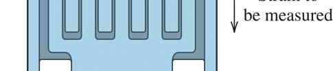
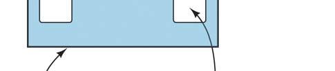
 4. THEORETICAL: EMISSION AND SUSCEPTIBILITY There are many ways for the electromagnetic-interference to be coupled to the pressure sensor, i.e, via printed-circuit board tracks, internal wiring which acts
Real Analog - Circuits 1 Chapter 1: Lab Projects
 Real Analog Circuits 1 Chapter 1: Lab Projects 1.4.1: DusktoDawn Light Overview: In this lab, we will create our first circuit which appears to do something which is readily perceivable without instrumentation.
BJT. Bipolar Junction Transistor BJT BJT 11/6/2018. Dr. Satish Chandra, Assistant Professor, P P N College, Kanpur 1
 BJT Bipolar Junction Transistor Satish Chandra Assistant Professor Department of Physics P P N College, Kanpur www.satish0402.weebly.com The Bipolar Junction Transistor is a semiconductor device which
Alternating current circuits- Series RLC circuits
 FISI30 Física Universitaria II Professor J.. ersosimo hapter 8 Alternating current circuits- Series circuits 8- Introduction A loop rotated in a magnetic field produces a sinusoidal voltage and current.
Ohm's Law and DC Circuits
 Physics Lab II Ohm s Law Name: Partner: Partner: Partner: Ohm's Law and DC Circuits EQUIPMENT NEEDED: Circuits Experiment Board Two Dcell Batteries Wire leads Multimeter 100, 330, 560, 1k, 10k, 100k, 220k
Accurate Models for Spiral Resonators
 MITSUBISHI ELECTRIC RESEARCH LABORATORIES http://www.merl.com Accurate Models for Spiral Resonators Ellstein, D.; Wang, B.; Teo, K.H. TR1-89 October 1 Abstract Analytically-based circuit models for two
CHAPTER 7. Response of First-Order RL and RC Circuits
 CHAPTER 7 Response of First-Order RL and RC Circuits RL and RC Circuits RL (resistor inductor) and RC (resistor-capacitor) circuits. Figure 7.1 The two forms of the circuits for natural response. (a) RL
OPERATIONAL AMPLIFIERS (OP-AMPS) II
 II") OPERATIONAL AMPLIFIERS (OP-AMPS) II LAB 5 INTRO: INTRODUCTION TO INVERTING AMPLIFIERS AND OTHER OP-AMP CIRCUITS GOALS In this lab, you will characterize the gain and frequency dependence of inverting op-amp
OPERATIONAL AMPLIFIERS (OP-AMPS) II LAB 5 INTRO: INTRODUCTION TO INVERTING AMPLIFIERS AND OTHER OP-AMP CIRCUITS GOALS In this lab, you will characterize the gain and frequency dependence of inverting op-amp
UNIVERSITY OF NORTH CAROLINA AT CHARLOTTE Department of Electrical and Computer Engineering
 UNIVERSITY OF NORTH CAROLINA AT CHARLOTTE Department of Electrical and Computer Engineering EXPERIMENT 2 BASIC CIRCUIT ELEMENTS OBJECTIVES The purpose of this experiment is to familiarize the student with
Introduction... 1 Part I: Getting Started with Circuit Analysis Part II: Applying Analytical Methods for Complex Circuits...
 Contents at a Glance Introduction... 1 Part I: Getting Started with Circuit Analysis... 5 Chapter 1: Introducing Circuit Analysis...7 Chapter 2: Clarifying Basic Circuit Concepts and Diagrams...15 Chapter
Testing and Stabilizing Feedback Loops in Today s Power Supplies
 Keywords Venable, frequency response analyzer, impedance, injection transformer, oscillator, feedback loop, Bode Plot, power supply design, open loop transfer function, voltage loop gain, error amplifier,
Component modeling. Resources and methods for learning about these subjects (list a few here, in preparation for your research):
:") Component modeling This worksheet and all related files are licensed under the Creative Commons Attribution License, version 1.0. To view a copy of this license, visit http://creativecommons.org/licenses/by/1.0/,
Component modeling This worksheet and all related files are licensed under the Creative Commons Attribution License, version 1.0. To view a copy of this license, visit http://creativecommons.org/licenses/by/1.0/,