Instruction Manual. The new high-performance inverter VF-AS1. 200V class kW 400V class kW NOTICE
|
|
|
- Blanche Watkins
- 5 years ago
- Views:
Transcription
1 E Safety precautions Introduction I II Contents Instruction Manual The new high-performance inverter TOSVERT TM 200V class 0.475kW 400V class kW NOTICE VF-AS1 1.Make sure that this instruction manual is delivered to the end user of the inverter unit. 2.Read this manual before installing or operating the inverter unit, and store it in a safe place for reference. Read first Connection equipment Operations Searching and setting parameters Basic parameters Extended parameters Operation with external signal Monitoring the operation status Taking measures to satisfy the CE/UL/CSA standards Selection of peripheral devices Table of parameters Specifications Before making a service call Inspection and maintenance Warranty Disposal of the inverter
2 E I. Safety precautions I The items described in these instructions and on the inverter itself are very important so that you can use the inverter safely prevent injury to yourself and other people around you as well as prevent damage to property in the area. Thoroughly familiarize yourself with the symbols and indications shown below and then continue to read the manual. Make sure that you observe all cautions given. Explanation of markings Marking Meaning of marking Warning Indicates that errors in operation may lead to death or serious injury. Caution Indicates that errors in operation may lead to injury (*1) to people or that these errors may cause damage to physical property. (*2) (*1) Such things as injury, burns or shock that will not require hospitalization or long periods of outpatient treatment. (*2) Physical property damage refers to wide-ranging damage to assets and materials. Meanings of symbols Marking Meaning of marking Indicates prohibition (Don't do it). What is prohibited will be described in or near the symbol in either text or picture form. Indicates something mandatory (must be done). What is mandatory will be described in or near the symbol in either text or picture form. Indicates warning. What is warned will be described in or near the symbol in either text or picture form. Indicates caution. What the caution should be applied to will be described in or near the symbol in either text or picture form. Limits in purpose This inverter is used for controlling speeds of three-phase induction motors in general industrial use. Safety precautions This product is intended for general purpose uses in industrial application. It cannot be used applications where may cause big impact on public uses, such as power plant and railway, and equipment which endanger human life or injury, such as nuclear power control, aviation, space flight control, traffic, safety device, amusement, or medical. It may be considerable whether to apply, under the special condition or an application where strict quality control may not be required. Please contact your Toshiba distributor. Please use our product in applications where do not cause serious accidents or damages even if product is failure, or please use in environment where safety equipment is applicable or a backup circuit device is provided outside the system. Do not use the inverter for loads other than those of properly applied three-phase induction motors in general industrial use. (Use in other than properly applied three-phase induction motors may cause an accident.) When the inverter is used to control the operation of a permanent magnet motor, a combination test must be conducted in advance. For details on the test, contact your Toshiba distributor. 1
3 E I General Operation Warning Never disassemble, modify or repair. This can result in electric shock, fire and injury. For repairs, call your sales agency. Reference 2. Disassembly prohibited Prohibited Mandatory Prohibited contact Never remove the front cover when power is on or open door if enclosed in a cabinet. The unit contains many high voltage parts and contact with them will result in electric shock. Don't stick your fingers into openings such as cable wiring hole and cooling fan covers. This can result in electric shock or other injury. Don't place or insert any kind of object into the inverter (electrical wire cuttings, rods, wires). This can result in electric shock or fire. Do not allow water or any other fluid to come in contact with the inverter. This can result in electric shock or fire. Turn power on only after attaching the front cover or closing door if enclosed in a cabinet. If power is turned on without the front cover attached or closing door if enclosed in a cabinet, this can result in electric shock or other injury. If the inverter begins to emit smoke or an unusual odor, or unusual sounds, immediately turn power off. If the equipment is continued to operate in such a state, the result may be fire. Call your local sales agency for repairs. Always turn power off if the inverter is not used for long periods of time since there is a possibility of malfunction caused by leaks, dust and other material. The leakage current caused by the contamination may result in fire. Caution Do not touch any radiating fins or radiating resistors. They can become very hot, and you may get burned if you touch them Reference 3. 2
4 Transportation & installation Prohibited Mandatory Warning Do not install or operate the inverter if it is damaged or any component is missing. This can result in electric shock or fire. Please consult your local sales agency for repairs. Do not place any inflammable objects nearby. If a flame is emitted due to malfunction, it may result in a fire. Do not install in any location where the inverter could come into contact with water or other fluids. This can result in electric shock or fire. Must be used in the environmental conditions prescribed in the instruction manual. Use under any other conditions may result in malfunction. Must be installed in non-inflammables such as metals. The rear panel gets very hot. If installation is in an inflammable object, this can result in fire. Do not operate with the front panel cover removed. Doing so could result in electric shock. An emergency stop device must be installed that fits with system specifications (e.g. shut off input power then engage mechanical brake). Operation cannot be stopped immediately by the inverter alone, thus risking an accident or injury. All options used must be those specified by Toshiba. The use of any other option may result in an accident. E Reference I Prohibited Caution When operating, do not hold by the front panel covers. The covers may come off and the unit will drop out resulting in injury. Do not install in any area where the unit would be subject to large amounts of vibration. That could result in the unit falling, resulting in injury...do not expose the drive to halogen group disinfectants. Failure to comply may cause damage to the electrical components in the drive. Models (20kg or more in weight) designed for 200V-18.5kW or larger and 400V-22kW or larger should be carried by 2 people more, or it could fall and cause an injury. Handle large capacity models using a crane. Lifting heavy inverters can cause injury to persons. Taking care of safety for users, handle carefully in order not to damage the inverter. Carefully lift up the inverter, hanging wires on the hanging bolts or holes on the top or bottom of the inverter. Reference Mandatory Note 1: Always keep the two sling ropes in balance when lifting the inverter, and take care that unexpected force does not apply to the inverter during lifting. Note 2: Always protect the inverter with a cover when transporting it. Note 3: Do not put your hand in the wiring port or do not hold it when transporting the inverter. The main unit must be installed on a base that can bear the unit's weight. If the unit is installed on a base that cannot withstand that weight, the unit may fall resulting in injury. Install a mechanical brake whenever the motor requires a brake (device which retains the motor shaft). Failure to do so could lead to injury to persons because the inverter itself has no function of mechanically retaining the brake shaft
5 E I Wiring Prohibited Mandatory Be Grounded Prohibited Warning Do not connect input power to the output (motor side) terminals (U/T1,V/T2,W/T3) of the inverter. Doing so will destroy the inverter and may result in fire. Do not connect resistors to the DC terminals (e.g., PA/+ and PC/-, or PO and PC/-). That may cause a fire. Connect resistors as directed by the instructions for Installing separate braking resistors. Within 15 minutes after turning off input power, do not touch wires of devices (MCCB) connected to the input side of the inverter. That could result in electric shock. Switch the grounding capacitor switch according to installation requirements. If the switch is incorrect, that may result in fire or malfunction. Electrical construction work must be done by a qualified expert. Connection of input power by someone who does not have that expert knowledge may result in fire or electric shock. Connect output terminals (motor side) correctly. If the phase sequence is incorrect, the motor will operate in reverse and that may result in injury. Wiring must be done after installation. If wiring is done prior to installation that may result in injury or electric shock. The following steps must be performed before wiring. (1) Turn off all input power to the inverter. (2) Wait at least 15 minutes and check to make sure that the charge lamp is no longer lit. (3) Use a tester that can measure DC voltage 800VDC or more, and check to make sure that the voltage to the DC main circuits (between PA/+ and PC/-) is 45V or less. If these steps are not properly performed, the wiring will cause electric shock. Tighten the screws on the terminal board to specified torque. If the screws are not tightened to the specified torque, it may lead to fire. Check to make sure that the input power voltage is +10%, -15% of the rated power voltage written on the rating label (±10% when the load is 100% in continuous operation). If the input power voltage is not +10%, -15% of the rated power voltage (±10% when the load is 100% in continuous operation) this may result in fire. Ground must be connected securely. If the ground is not securely connected, it could lead to electric shock or fire when a malfunction or current leak occurs. Caution Do not attach equipment (such as noise filters or surge absorbers) that have built-in capacitors to the output (motor side) terminals. That could result in a fire. Reference Reference 2.1 Caution Caution Charged capacitors can present a shock hazard even after source power is removed. Drives with EMC filters will retain a charge on the input terminals for up to 15 min. after the power has been removed. To avoid electrical shock, don t touch the connector terminals and uninsulated source cables at either the main circuit disconnect or the drive until the capacitive charge has dissipated. 4
6 Operations Prohibited Mandatory Warning Do not touch inverter terminals when electrical power is applied to the inverter even if the motor is stopped. Touching the inverter terminals while power is connected to it may result in electric shock. Do not touch switches when thands are wet and do not try to clean the inverter with a damp cloth. Such practices may result in electric shock. Do not go near the motor in alarm-stop status when the retry function is selected. The motor may suddenly restart and that could result in injury. Take measures for safety, e.g. attaching a cover to the motor, against accidents when the motor unexpectedly restarts. The inverter is tuned automatically (auto-tuning =, ) when the inverter is started for the first time after setup. During auto-tuning, which takes several seconds, the motor is energized, although it is standing still. Noise may be produced by the motor during auto-tuning, which, however, does not indicate that something is wrong with the inverter or the motor. Do not set the stall prevention level () extremely low. If the stall prevention level parameter () is set at or below the no-load current of the motor, the stall preventive function will always be active and increase the frequency when it judges that regenerative braking is taking place. Do not set the stall prevention level parameter () below 30% under normal use conditions. Do not turn on the power before attaching the front cover. When storing inside the cabinet and using with the front cover removed, always close the cabinet doors first and then turn power on. If the power is turned on with the front cover or the cabinet doors open, it may result in electric shock. Make sure that operation signals are off before resetting the inverter after malfunction. If the inverter is reset before turning off the operating signal, the motor may restart suddenly causing injury. Provide cranes and hoists with sufficient circuit protection such as mechanical braking. Without sufficient circuit protection, the resulting insufficient motor torque during tuning could create a risk of machine stalling/falling. E Reference I Mandatory Caution Observe all permissible operating ranges of motors and mechanical equipment. (Refer to the motor's instruction manual) Not observing these ranges may result in injury. Reference 3. When sequence for restart after a momentary failure is selected Mandatory Caution Stand clear of motors and mechanical equipment. If the motor stops due to a momentary power failure, the equipment will start suddenly when power is restored. This could result in unexpected injury. Attach cautions about sudden restart after a momentary power failure on inverters, motors and equipment for prevention of accidents in advance. When retry function is selected Mandatory Caution Stand clear of motors and equipment. If the motor and equipment stop when the alarm is given, selection of the retry function will restart them suddenly after the specified time has elapsed and alarm condition has disappeared. This could result in unexpected injury. To prevent accidents, stick caution notices that the inverter has a retry function to the inverter, the motor and the machine. Reference Reference
7 E I Maintenance and inspection Warning Reference Prohibited Mandatory Never replace any part by yourself. This could be a cause of electric shock, fire and bodily injury. To replace parts, call the local sales agency. The equipment must be inspected every day. If the equipment is not inspected and maintained, errors and malfunctions may not be discovered which could lead to accidents. Before inspection, perform the following steps. (1) Turn off all input power to the inverter. (2) Wait at least 15 minutes and check to make sure that the charge lamp is no longer lit. (3) Use a tester that can measure DC voltage 800VDC or more, and check to make sure that the voltage to the DC main circuits (between PA/+ and PC/-) is 45V or less. If inspection is performed without performing these steps first, it could lead to electric shock Disposal Mandatory Caution If you throw away the inverter, have it done by a specialist in industry waste disposal*. If you throw away the inverter by yourself, this can result in explosion of capacitor or produce noxious gases, resulting in injury. (*) Persons who specialize in the processing of waste and known as industrial waste product collectors and transporters or industrial waste disposal persons. If the collection, transport and disposal of industrial waste is done by someone who is not licensed for that job, it is a punishable violation of the law. (Laws in regard to cleaning and processing of waste materials) Reference 16. Attach caution labels Shown here are examples of caution labels to prevent, in advance, accidents in relation to inverters, motors and other equipment. If the inverter has been programmed for auto-restart function after momentary power failure or retry function, place caution labels in a place where they can be easily seen and read. If the inverter has been programmed for restart sequence of momentary power failure, place caution labels in a place where they can be easily seen and read. (Example of caution label) Caution (Functions programmed for restart) Do not go near motors and equipment. Motors and equipment that have stopped temporarily after momentary power failure will restart suddenly after recovery. If the retry function has been selected, place caution labels in a location where they can be easily seen and read. (Example of caution label) Caution (Functions programmed for retry) Do not go near motors and equipment. Motors and equipment that have stopped temporarily after an alarm will restart suddenly after the specified time has elapsed and alarm condition has disappeared. 6
8 E II. Introduction Thank you for your purchase of the Toshiba TOSVERT VF-AS1 industrial inverter. II This instruction manual is intended for inverters with CPU version 154 or later. The CPU version will be frequently upgraded. 7
9 E Contents - I. Safety precautions 1 I I. Introduction 7 1. Read first A Check the product A Contents of the product code A Structure of the main body A Names and functions A Detaching the cover A Grounding capacitor switching method A Installing the DC reactor A Notes on the application A Motors A Inverters A Measure to take against leakage Current A Installation A Connection equipment B Cautions on wiring B Standard connections B Description of terminals B Main circuit terminals B Control circuit terminal block B RS485 communication connector B Operations C Setting/monitor modes C Simplified operation of the VF-AS1 C Terminal board operation C Panel operation C-7 4. Searching and setting parameters D How to set parameters D Setting parameters in the selected quick mode D Setting parameters in the standard setting mode D Functions useful in searching for a parameter or changing a parameter setting D-4 5. Basic parameters E History function E Setting acceleration/deceleration time E Automatic acceleration/deceleration E Manually setting acceleration/deceleration time E Increasing starting torque E Setting parameters by operating method E Selection of operation mode E Selecting control mode E Manual torque boost increasing torque boost at low speeds E Base frequency E Maximum frequency E Upper limit and lower limit frequencies E Setting frequency command characteristics E Preset speed operation (speeds in 15 steps) E Selecting forward and reverse runs (operation panel only) E Setting the electronic thermal E Changing the display unit % to A (ampere)/v (volt) E Meter setting and adjustment E-27 i
10 E PWM carrier frequency E Trip-less intensification E Auto-restart (Restart during coasting) E Regenerative power ride-through control/deceleration stop during power failure/ Synchronized acceleration/deceleration E Dynamic (regenerative) braking - For abrupt motor stop E Standard default setting E Searching for all reset parameters and changing their settings E EASY key function E Extended parameters F Input/output parameters F Low-speed signal F Putting out signals of arbitrary frequencies F Input signal selection F Priority when forward/reverse run commands are entered simultaneously F Assigning priority to the terminal board in the operation panel and operation mode F Analog input signal switching F Terminal function selection F Keeping an input terminal function always active (ON) F Modifying input terminal functions F Using the servo lock function F Modifying output terminal functions F Response time of input/output terminals F Using the V/f adjustment function F Basic parameters 2 F Switching among V/f characteristics 1, 2, 3 and 4 from input terminal F V/f 5-point setting F Speed command switching F Using two types of frequency speed commands F Operation frequency F Start frequencystop frequency F Run/Stop control with frequency setting signals F Frequency setting signal 0Hz dead zone handling function F DC braking F DC braking F Motor shaft fixing control F Function of issuing a 0Hz command during a halt F Auto-stop in case of lower-limit frequency continuous operation (Sleep/Wake-up function) F Jog run mode F Setting frequency via external contact input (Motor operated pot mop setting) F Jump frequency - jumping resonant frequencies F Preset speed operation frequencies F Preset speed operation frequency 8 to 15 F Forced oeration control F Trip-less intensification F Retry function F Avoiding overvoltage tripping F Output voltage adjustment/supply voltage correction F Reverse run prohibition F Output voltage waveform selection F Drooping control F Light-load high-speed operation function F Braking function F Acceleration/deceleration suspend function F Commercial power/inverter switching F PID control F Stop position control function F-38 ii
11 E Setting motor constants F Increasing the motor output torque further in low speed range F Torque control F Torque command F Speed limits in torque control mode F Selection of tension torque bias input and load sharing gain input F Torque limit F Torque limit switching F Torque limit mode selection at acceleration/deceleration F Stall prevention function F Power running stall continuous trip detection time F Regenerative braking stall prevention mode selection F Stall prevention control switching F Current and speed control adjustment F Current and speed control gain F Prevention of motor current oscillation at light load F Max output voltage modulation rate F Fine adjustment of frequency setting signal F Operating a synchronous motor F Acceleration/deceleration 2 F Setting acceleration/deceleration patterns and switching acceleration/deceleration patterns 1, 2, 3 and 4 F Pattern operation F Preset speed mode F Protection functions F Setting of stall prevention level F Inverter trip record retention F Emergency stop F Output phase failure detection F OL reduction starting frequency F Motor 150%-overload time limit F Input phase failure detections F Control mode for low current F Detection of output short circuit F Overtorque trip F Cooling fan control selection F Cumulative operation time alarm setting F Abnormal speed detection F Overvoltage limit operation F Undervoltage trip F Regenerative power ride-through control level F Braking answer waiting time F VI/II analog input wire breakage detection level F Guide to time of replacement F Rush current suppression relay activation time F Motor thermal protection F Braking resistance overload curve F Selection of a restart condition for the motor stopped with a mechanical brake F Protection against a failure of the control power backup device (optional CPS002Z) F Ground fault detection selection F Disconnection detection of remote keypad F Override F Adjustment parameters F Pulse train output for meters F Setting of optional meter outputs F Calibration of analog outputs F Operation panel parameter F Prohibition of key operations and parameter settings F-73 iii
12 E Displaying the rotational speed of the motor or the line speed F Changing the steps in which the value displayed changes F Changing the standard monitor display F Canceling the operation command F Selection of operation panel stop pattern F Setting of a torque command in panel operation mode F Torque-related parameters for panel operation F Tracing functions F Integrating wattmeter F Communication function F wire RS485/4-wire RS485 F Open network option F My function F Traverse function F Instruction manuals for optionally available devices and special functions F Operation with external signal G External operation G Applied operation with input and output signals (operation by terminal board) G Functions of input terminals (in case of sink logic) G Functions of output terminals (incase of sink logic) G Setup of input terminal operation time G Analog input filter G Setup of external speed command (analog signal) G Setup by analog input signals (RR/S4 terminal) G Setup by analog input signals (VI/II terminal) G Setup by analog input signals (RX terminal) G Monitoring the operation status H Screen composition in the status monitor mode H Monitoring the status H Status monitor under normal conditions H Display of detailed information on a past trip H Changing status monitor function H Display of trip information H Trip code display H Monitor display at tripping H Display of alarm, pre-alarm, etc. H Taking measures to satisfy the CE/UL/CSA standards I How to cope with the CE standard I EMC directive I Measures to satisfy the EMC directive I Low-voltage directive I Measures to be taken to satisfy the low-voltage directive I Measures to be taken to satisfy the UL/CSA standards I Caution in installing the inverter I Caution in wiring and rated current I Caution as to peripheral devices I Caution as to the protection of motors from overload I Selection of peripheral devices J Selection of wiring materials and devices J Installation of a magnetic contactor J Installation of an overload relay J Application and functions of options J Optional internal devices J-9 iv
13 E Connection of a DC power supply and other electric units J Connection of a single-phase 200V power supply J When using the inverter along with a DC power supply J Table of parameters K Specifications L Models and their standard specifications L Outside dimensions and weight L Before making a service call - Trip information and remedies M Trip causes/warnings and remedies M Method of resetting causes of trip M If the motor does not run while no trip message is displayed. M How to check other troubles M Inspection and maintenance N Regular inspection N Periodical inspection N Making a call for servicing N Keeping the inverter in storage N Warranty O Disposal of the inverter P-1 v


14 Risk of injury, electric shock or fire. Read the Instruction Manual. Do not open the cover while power is applied or for 15 minutes after power has been removed. Ensure proper earth connection. E Read first 1.1 Check the product Before using the product you have purchased, check to make sure that it is exactly what you ordered. Caution Use an inverter that conforms to the specifications of the power supply and three-phase induction motor being used. If the inverter being used does not conform to those specifications, not only will Mandatory the three-phase induction motor not rotate correctly, but it may cause serious accidents through overheating and fire. 1 Type indication Inverter main unit Name plate VF-AS1 3PH-200/240V 3.7kW/5HP Series name Power supply Motor capacity Type indication Carton box Warning label Name plate Type indication label Warning label Instruction manual This manual 1. 2 Contents of the product code DANGER Inverter Type Applicable motor Invert rated output capacity Power supply Related input current Related output current Serial No. Explanation of the type and form written on the label. Type Form Model name TOSVERT VF-AS1 series Voltage class 2:200V~240V 4:380V~480V Applicable motor capacity 004:0.4kW 007:0.75kW 015:1.5kW 022:2.2kW 037:3.7/4.0kW 055:5.5kW 075:7.5kW 110:11kW 150:15kW 185:18.5kW 220:22kW 300:30kW 370:37kW 450:45kW 550:55kW 750:75kW 900:90kW 110K:110kW 132K:132kW 160K:160kW 200K:200kW 220K:220kW 280K:280kW 355K:355kW 400K:400kW 500K:500kW Operation panel P:Provided Additional functions II L: Built-in EMC filter F:External heat sink + Y:Others basic filter M: Built-in basic (non-standard) C: Built-in EMC filter Additional functions I Special specification code Default interface logic (*1) H1,HN: US Negative WN: Negative WP: Positive Special specification code A:Special specification code (is a number) *1): This code represents the factory default logic setting. You can switch from one input/output logic to the other using slide switch SW1. For more details, refer to Section Warning : Always shut power off first then check the ratings label of inverter held in a cabinet. A-1

15 E Structure of the main body Names and functions 1) Outside view Control circuit terminal cover Operation panel 1 Be sure to close the cover before starting the operation to prevent persons from touching the terminal in error. Main circuit terminal cover Be sure to attach the cover before starting the operation to prevent persons from touching the terminal in error. Inverter type and production No. are on the back side of the control circuit terminal cover. [Front panel] Protective cover on the top [Note] Wiring port Ventilation slit Name plate Cooling fan [Bottom view] [Side view] Note: Remove this cover when installing the inverter side by side with other inverters where the ambient temperature will rise above 40 C. For more details, refer to Section A-2
16 E Operation panel RUN lamp EASY key [Note 1] EASY key lamp Up key % lamp Lights when an ON command is issued but no frequency signal is sent out. It blinks when operation is started. Press this key to control the function assigned with a parameter. Lights when the EASY key is enabled. Lights when the unit is %. PRG lamp Lights when the inverter is in parameter setting mode. Hz lamp Lights when the unit is Hz. MODE key 1 MON lamp Lights when the inverter is in monitor mode. Blinks when the inverter is placed in trip record display mode. Displays the operation frequency, a parameter, the cause of a failure, and so on. ENTER key RUN key lamp Up/Down key lamp Lights when the RUN key is enabled. RUN key Pressing this key while the RUN key lamp is lit starts the operation. STOP key Pressing this key while the RUN key lamp is lit causes the motor to make a deceleration stop. Press the key twice to reset the inverter after a trip. RS485 connector/cover 2-wire RS485 connector. This connector is used to connect an optional device, such as an extended control panel. With these keys, you can set the operation frequency while the Up/Down key lamp is lit. [Note 2] Down key Note 1: For details EASY Key functions, refer to Section Note 2: When parameter is set to, the operation frequency cannot be set even if this lamp is lit. A-3


 Screw")
17 E ) Main circuit terminal VFAS1-2004PL~2015PL VFAS1-4007PL~4022PL Shorting-bar 1 Grounding capacitor switch M4 screw Grounding terminal (M5 screw) Screw hole for EMC plate VFAS1-2022PL, 2037PL VFAS1-4037PL Shorting-bar Grounding capacitor switch M4 screw Grounding terminal (M5 screw) Screw hole for EMC plate VFAS1-2055PL VFAS1-4055PL, 4075PL Grounding capacitor switch Shorting-bar M5 screw Grounding terminal (M5 screw) Screw hole for EMC plate A-4
 Screw hole for EMC plate VFAS1-2185PM, 2220PM")

 directly into the holes in the front of the power terminal block.")
18 E VFAS1-2075PL VFAS1-4110PL Shorting-bar M5 screw Grounding capacitor switch Grounding terminal (M5 screw) Screw hole for EMC plate 1 VFAS1-2110PM, 2150PM VFAS1-4150PL, 4185PL Grounding capacitor switch Shorting-bar M6 screw Grounding terminal (M5 screw) Screw hole for EMC plate VFAS1-2185PM, 2220PM VFAS1-4220PL Grounding capacitor switch Grounding capacitor switch (400V model) M8 screw Shorting-bar A: -WN and WP products. B: -HN products only. Use crimped ring lugs of appropriate size on input and output cables. Attach to the top side of the terminal block only. Do not place wires in the hole of the terminal block. Insert the cables (stripped the appropriate length) directly into the holes in the front of the power terminal block. Tighten to recommended torque using the socket head cap screw provided in the terminal block. Grounding terminal (M8 screw) Screw hole for EMC plate Grounding terminal (M5 screw) A-5

 Screw hole for EMC plate Grounding terminal (M5 screw) VFAS1-2300PM~2450PM")

19 E VFAS1-4300PL, 4370PL Grounding capacitor switch M8 screw Shorting-bar A: -WN and WP products. B: -HN products only. 1 Use crimped ring lugs of appropriate size on input and output cables. Attach to the top side of the terminal block only. Do not place wires in the hole of the terminal block. Insert the cables (stripped the appropriate length) directly into the holes in the front of the power terminal block. Tighten to recommended torque using the socket head cap screw provided in the Grounding terminal (M8 screw) Screw hole for EMC plate Grounding terminal (M5 screw) VFAS1-2300PM~2450PM VFAS1-4450PL~4750PL Grounding capacitor switch M12 screw Shorting-bar A: -WN and WP products. B: -HN products only. Use crimped ring lugs of appropriate size on input and output cables. Attach to the top side of the terminal block only. Do not place wires in the hole of the terminal block. Insert the cables (stripped the appropriate length) directly into the holes in the front of the power terminal block. Tighten to recommended torque using the socket head cap screw provided in the terminal block. Grounding terminal (M12 screw) Screw hole for EMC plate Grounding terminal (M8 screw) VFAS1-2550P VFAS1-4900PC M12 screw M10 screw Grounding capacitor switching bar M8 screw Grounding terminal(m10 screw) A-6


 A-7")
20 E VFAS1-2750P VFAS1-4110KPC M12 screw M10 screw Grounding capacitor switching bar M4 screw 1 M8 screw Grounding terminal(m10 screw) VFAS1-4132KPC M12 screw M10 screw Grounding capacitor switching screw M10 screw M4 screw Grounding terminal(m10 screw) VFAS1-4160KPC M12 screw M12 screw Grounding capacitor switching screw M10 screw M4 screw Grounding terminal(m12 screw) A-7


 A-8")
21 E VFAS1-4200KPC~4280KPC 1 M12 screw Grounding capacitor switching screw M12 screw M4 screw Grounding terminal (M12 screw) VFAS1-4355KPC, 4400KPC Grounding capacitor switching screw M12 screw M4 screw M12 screw Grounding terminal (M12 screw) VFAS1-4500KPC Grounding capacitor switching screw M12 screw M4 screw M12 screw Grounding terminal (M12 screw) A-8
 4-wire RS485 connector Control circuit terminal block screw size: M3")
22 E ) Control circuit terminal block The control circuit terminal block is common to all equipment. 1 ST-CC Shorting bar (VFAS1-****-H1, -HN, -WN) 4-wire RS485 connector Control circuit terminal block screw size: M3 For details on all terminal functions, refer to Section Detaching the cover Main circuit terminal cover To wire the main circuit terminal for models 200V-15kW or smaller and 400V-18.5kW or smaller, remove the main circuit terminal cover in line with the steps given below. (A) (B) 90 (1) (2) Main circuit terminal Open the main circuit terminal cover. * To open the cover, lift it with your finger placed at the part on the right side of the cover. Remove the main circuit terminal cover. (1) Turn the screw securing the cover counterclockwise by 90 to release the lock (Do not turn the screw by more than 90. Or else the screw might be broken.) (2) Hold the cover by both ends, and then pull up the cover with slightly bending it inward. A-9
 on the main circuit terminal cover if necessary for connecting the cables from the power supply. 200V-0.4kW~3.7/4.")

 (B) (2) (1) (3) Control circuit terminal Open the control circuit terminal cover.")
23 E For 200V/0.4kW to 200V/15kW models and 400V/0.75kW to 400V/18.5kW models, cut off the tabs (part A in the figure below) on the main circuit terminal cover if necessary for connecting the cables from the power supply. 200V-0.4kW~3.7/4.0kW 400V-0.75kW~3.7/4.0kW 200V-5.5kW~15kW 400V-5.5kW~18.5kW 1 A A Front cover To wire the main circuit terminal for models 200V-18.5kW or more and 400V-22kW or more, remove the front cover. Remove the screw Control circuit terminal cover Main circuit terminal To wire the control circuit terminal, open the control circuit terminal cover in line with the steps given below. (A) (B) (2) (1) (3) Control circuit terminal Open the control circuit terminal cover. * To open the cover, lift it with your finger placed at the part on the right side of the cover. Remove the terminal, if necessary. * To do so, open the main circuit terminal cover, loosen the screws that fix the terminal, using a (-) screwdriver or torx (T20H) screwdriver, placed your finger on part and pull out the terminal. A-10
24 E Charge lamp This lamp is lit when a high voltage remains in the inverter. When removing the main circuit terminal cover or opening the front cover, be sure to check that this lamp is off and follow the instructions about wiring on page 4. The mounting position of the charge lamp varies from model to model. VFAS1-2004PL~2150PM VFAS1-4007PL~4185PL This lamp is placed behind the main circuit terminal cover. 1 Charge lamp VFAS1-2185PM~2450PM VFAS1-4220PL~4750PL VFAS1-2550P, 2750P VFAS1-4900PC~4500KPC Charge lamp Charge lamp A-11
25 E Grounding capacitor switching method The inverter is grounded through a capacitor. The leakage current from the inverter can be reduced using the selector switch, switching bar or switching screw (depending on the model). This switching device is used to detach the capacitor from the grounding circuit or to reduce its capacitance. Some models have capacitors that can be detached completely, while others have capacitances that can be reduced. Note 1:Without the capacitor, the inverter does not comply with the EMC directive V/45kW - 400V/75kW models and smaller: Grounding capacitor switch Prohibited Warning When attaching or detaching the capacitor, be sure to turn off power. When the grounding capacitor is detached from the inverter with a capacity of 400V-3.7kW or less, be sure to set the carrier frequency () to 4kHz or less. If the carrier frequency is set above 4kHz, the inverter may overheat and become damaged. When the grounding capacitor is detached from the inverter and the cables connecting the inverter to the motor are 100 m or more in length with a capacity between 400V-5.5kW and 400V-18.5kW, be sure to set the carrier frequency () to 4kHz or less. If the carrier frequency is set above 4kHz, the inverter may overheat and become damaged. When installing or operating the inverter within an ungrounded system or within a high-resistance grounding system, set the grounding capacitor switch to Small. Any other setting may result in a system malfunction or overheating. 200V 0.4kW15kW 400V 0.75kW18.5kW 200V 0.4kW~7.5kW, 18.5kW, 22kW 400V 0.75kW~18.5kW To connect to the ground, push in. (Factory default position) *3 *1 *3 To disconnect fom the ground, pull up. *1: Refer to Section for the position of the switch. 200V 18.5kW45kW 400V 22kW75kW *3: For 400V-3.7kW model and less, the switch is fixed with a label saying CF/SFr4kHz. If such a label is affixed to your inverter, you should set the carrier frequency () at 4kHz or less according to the instructions when switching. 200V 11kW, 15kW, 30kW~45kW 400V 22kW~75kW Large Small To change the capacitance to Large, push in. (Factory default position) Large Small *2: Refer to next pages for the position of the switch. To change the capacitance to Small, pull up. A-12


26 E V kW 400V 22kW 200V/400V class Grounding capacitor switch Large Small Small Large 1 Only 400V class 400V 30kW37kW Grounding capacitor switch Small Large 200V 30kW45kW 400V 45kW75kW Grounding capacitor switch Large Small A-13
27 E V/55kW models and larger 400V/90kW, 110kW models: Grounding capacitor switching bar 1 Large Small Large Small To change the capacitance to Large, secure the upper end of the grounding capacitor switching bar to the inverter chassis with a screw. To change the capacitance to Small, remove the screw that fixes the upper end of the grounding capacitor switching bar and turn the switching bar, as shown in the figure. (Factory default position) Prohibited Warning In case of one phase grounding system (A three-phase supply power is connected in delta), isolated neutral system, or high resistance grounding system, do not change the connection of grounding capacitor before factory setting. If connection changed (this means the capacitance is increased), the capacitor may become damaged. Note: If a neutral grounding system is used, 400V-90kW and 110kW models meet required EMC directive by changing the connection of the grounding capacitor as shown in the figure at the top (changing the capacitance from Small to Large). 400V/132kW models and larger: Grounding capacitor screw «132kW, 160kW» Large Small A B To change the capacitance to Large, fix to A with the grounding capacitor screw. Large Small A B To change the capacitance to Small, fix to B with the grounding capacitor screw. (Factory default position) Prohibited Warning In case of one phase grounding system (A three-phase supply power is connected in delta), isolated neutral system, or high resistance grounding system, do not change the connection of grounding capacitor before factory setting. If connection changed (this means the capacitance is increased), the capacitor may become damaged. Note: If a neutral grounding system is used, changing the connection of the grounding capacitor as shown in the figure at the top (changing the capacitance from Small to Large) makes the inverter compliant with the EMC directive. A-14
28 E «200kW~280kW» Large Small To change the capacitance to Large, fix to A with the grounding capacitor screw. A B Large Small To change the capacitance to Small, fix to B with the grounding capacitor screw. (Factory default position) 1 Prohibited Warning In case of one phase grounding system (A three-phase supply power is connected in delta), isolated neutral system, or high resistance grounding system, do not change the connection of grounding capacitor before factory setting. If connection changed (this means the capacitance is increased), the capacitor may become damaged. Note: If a neutral grounding system is used, changing the connection of the grounding capacitor as shown in the figure at the top (changing the capacitance from Small to Large) makes the inverter compliant with the EMC directive. «355kW~500kW» Large Small To change the capacitance to Large, fix to A with the grounding capacitor screw. A A B B Large Small To change the capacitance to Small, fix to B with the grounding capacitor screw. (Factory default position) Prohibited Warning In case of one phase grounding system (A three-phase supply power is connected in delta), isolated neutral system, or high resistance grounding system, do not change the connection of grounding capacitor before factory setting. If connection changed (this means the capacitance is increased), the capacitor may become damaged. Note: If a neutral grounding system is used, changing the connection of the grounding capacitor as shown in the figure at the top (changing the capacitance from Small to Large) makes the inverter compliant with the EMC directive. A-15
 (1) (2) Reactor unit Reactor case 1 Front cover Remove the front cover.")
 (4) Top panel Cover Front panel Connect the reactor unit to the PO and PA/+ terminals on the main-circuit terminal board.")
29 E Installing the DC reactor How to install (Example: VFAS1-4160KPC) (1) (2) Reactor unit Reactor case 1 Front cover Remove the front cover. Mount the reactor case on an inner wall of the cabinet and secure the reactor unit to the case with screws. (3) (4) Top panel Cover Front panel Connect the reactor unit to the PO and PA/+ terminals on the main-circuit terminal board. Then connect the supplied earth wire. See the figures on the next page. Fix the front cover after connecting. Secure the cover, front panel and top panel to the reactor case with screws. A-16

30 E Example of wiring of each model «VFAS1-2550P, 2750P» «VFAS1-4900PC~4132KPC» «VFAS1-4160KPC~4280KPC» 1 Earth cable PO PA/+ PO PA/+ Earth cable «VFAS1-4355KPC~4500KPC» PO.1 PA/+ PO.2 Earth cable 1.4 Notes on the application Motors Keep the following in mind when using the VF-AS1 to drive a motor. Mandatory Caution Use an inverter that conforms to the specifications of power supply and three-phase induction motor being used. If the inverter being used does not conform to those specifications, not only will the three-phase induction motor not rotate correctly, but it may cause serious accidents through overheating and fire. Comparisons with commercial power operation The VF-AS1 Inverter employs the sinusoidal PWM system to supply the motor. This is why compared to operation with a commercial power there will be a slight increase in motor temperature, noise and vibration. The main supply voltage and current will also be distorted due to harmonic distortion while increase the line current. Operation in the low-speed area When running continuously at low speed in conjunction with a general purpose motor, there may be a decline in that motor's cooling effect. If this happens, operate with the output decreased from rated load. To carry out low-speed operation continuously at the rated torque, we recommend to use a inverter rated motor or a forced cooled motor designed for use with an inverter. When operating in conjunction with a inverter rated motor, you must change the inverter's motor overload protection level to VF motor use (). Adjusting the overload protection level The VF-AS1 Inverter protects against overloads with its electronic thermal overload detection circuits. The electronic thermal's reference current of the inverter must be adjusted in line with the rated current of the motor being used in combination. A-17
31 E High-speed operation at and above 50Hz/60Hz (rated frequency) Operating at frequencies greater than 50Hz/60Hz will increase noise and vibration. There is also a possibility that such operation will exceed the motor's mechanical strength under these conditions and the bearing limits. You should verify with the motor's manufacturer operating. Method of lubricating load mechanisms Operating an oil-lubricated reduction gear and gear motor in the low-speed areas will worsen the lubricating effect. Check with the manufacturer to find out about operable speed range. 1 Low loads and low inertia loads The motor may demonstrate instability such as abnormal vibrations or overcurrent trips at light loads of 50% or under of the rated load, or when the load's moment of inertia is extremely small. If that happens reduce the carrier frequency. Occurrence of instability Unstable phenomena may occur under the load and motor combinations shown below. Combined with a motor that exceeds applicable motor ratings recommended for the inverter Combined with special motors To deal with the above lower the settings of inverter carrier frequency. (When performing vector control, set the carrier frequency at 2kHz or more. If the carrier frequency is set below 2kHz, it will be automatically corrected to 2kHz by the inverter.) Combined with couplings between load devices and motors with high backlash In this case, set the S-pattern acceleration/deceleration function and adjust the response time inertial moment setting during vector control or switch to V/f control (=). Combined with loads that have sharp fluctuations in rotation such as piston movements In this case, adjust the response time inertial moment setting during vector control or switch to V/f control (=). If it is operated in vector control mode (For torque control mode), only a motor whose capacity is same as inverter standard or 1 size smaller should applied. Braking a motor when power supply is lost A motor with its power cut off goes into freewheel, and does not stop immediately. To stop the motor quickly as soon as the power is cut off install an auxiliary brake. There are different kinds of brake devices, both electrical and mechanical. Select the brake that is best for the system. Loads that generate negative torque When combined with loads that generate negative torque the protection for overvoltage and overcurrent on the inverter will go into operation and may cause a trip. For this kind of situation, you must install a dynamic braking resistor, etc. that complies with the load conditions. Motor with brake If a brake motor is used with the braking circuit connected to the output terminals of the inverter, the brake cannot be released because of a voltage drop at startup. Therefore, when using the inverter along with a brake motor, connect the braking circuit to the power supply side of the inverter, as shown in the figure below. In most cases, the use of a brake motor causes an increase in noise at low-speed. (Non-exciting brake) MC2 (Non-exciting brake) MC2 B B MC1 Three-ph ase power supply FLB FLC ST CC MC3 IM MC1 Threephase power supply OUT1 P24 LOW IM MC1 MC3 LOW MC2 MC3 MC2 Circuit configuration 1 Circuit configuration 2 A-18
32 E In circuit configuration 1, the brake is turned on and off through MC2 and MC3. If the circuit is configured in some other way, the overcurrent trip may be activated because of the locked rotor current when the brake goes into operation. Circuit configuration 2 uses low-speed signal OUT1 to turn on and off the brake. Turning the brake on and off with a low-speed detection (OUT1 function) may be better in such applications as elevators. Please confer with your Toshiba distributor before designing the system. Measures to protect motors against surge voltages In a system in which a 400V-class inverter is used to control the operation of a motor, very high surge voltages may be produced. When applied to the motor coils repeatedly for a long time this can cause deterioration of their insulation, depending on the wire length, wire routing and types of wires used. Here are some examples of measures against surge voltages. (1) Lower the inverter s carrier frequency. (2) Set the parameter (Carrier frequency control mode selection) to or. (3) Use motors with a high dielectric strength. (4) Insert an reactor or a surge voltage suppression filter between the inverter and the motor Inverters Protecting inverters from overcurrent The inverter has an overcurrent protection function. The programmed current level is set to the inverter's maximum applicable motor. If the motor used has a small capacity, the stall prevention level, overcurrent level and the motor electronic thermal protection must be readjusted. If adjustment is necessary, refer to Section 5.14, and make adjustments as directed. Inverter capacity Do not operate a large capacity motor with a small capacity (kva) inverter even with light loads. Current ripple will raise the output peak current making it easier to set off the overcurrent trip. Power factor correction capacitor Power factor correction capacitors cannot be installed on the output side of the inverter. When a motor is run that has a power factor correction capacitor attached to it, remove the capacitors. This can cause inverter malfunction trips and capacitor destruction. Inverter U V IM W Remove the power factor correction capacitor and surge absorber Power factor correction Operating at other than rated voltage Connections to voltages other than the rated voltage described in the rating label cannot be made. If a connection must be made to a power supply other than one with rated voltage, use a transformer to raise or lower the voltage to the rated voltage. Circuit interrupting when two or more inverters are used on the same power line. (Circuit interrupting fuse) MCCB1 MCCB2 INV1 MCCB3 INV2 MCCBn INVn Breaking of selected inverter A-19
33 E There is no fuse in the inverter's main circuit. Thus, as the diagram above shows, when more than one inverter is used on the same power line, you must select interrupting characteristics so that only the MCCB2 will trip and the MCCB1 will not trip when a short occurs in the inverter (INV1). When you cannot select the proper characteristics install a circuit interrupting fuse between the MCCB2 and the INV1. 1 If power supply distortion is not negligible If the power supply distortion is not negligible because the inverter shares a power distribution line with other systems causing distorted waveforms, such as systems with thyristers or large-capacity inverters, install an input reactor to improve the input power factor, to reduce higher harmonics, or to suppress external surges. Disposal If an inverter is no longer usable, dispose of it as industrial waste Measure to take against leakage Current Caution Current may leak through the inverter's input/output wires because of insufficient electrostatic capacity on the motor with bad effects on peripheral equipment. The leakage current's value is affected by the carrier frequency and the length of the input/output wires. Test and adopt the following remedies against leakage current. (1) Effects of leakage current across ground Leakage current may flow not just through the inverter system but also through ground wires to other systems. Leakage current will cause earth leakage current breakers, leakage current relays, ground relays, fire alarms and sensors to operate improperly, and it will cause superimposed noise on the CRT screen or display of incorrect current values during current detection with the CT. Power supply inverter inverter Leakage current path across ground Remedies: There is the following method for reduce leakage current across ground. 1. Reduce PWM carrier frequency. The setting of PWM carrier frequency is done with the parameter. 2. If there is no radio-frequency interference or similar problem, detach the built-in noise filter capacitor. Refer to Section (For inverters of certain capacities, the PWM carrier frequency () must be set at 4 khz or below.) 3. Use high frequency remedial products for earth leakage breakers. If you use equipment like this, there is no need to reduce the PWM carrier frequency. 4. If the sensors and CRT are affected, it can be remedied by reducing the PWM carrier frequency described in 1 above, but if this cannot be remedied because of the increase in the motor's electric magnetic noise, please consult with your Toshiba distributor. * Cautions for applying models with a built-in noise filter. For the models with a built-in noise filter, the leakage current value at power supply of (delta) connecting wire (single-phase earth) can be larger than normal inverter, so be careful. <Standard leakage current value (single-phase earth)> VFAS1-2004PL~2150PM: Approx. 15mA VFAS1-2185PM~2450PM: Approx. 1mA A-20
34 E (2) Affects of leakage current across supply lines Thermal relay Power supply inverter Leakage current path across wires (1) Thermal relays The high frequency component of current leaking into electrostatic capacity between inverter output wires will increase the effective current values and make externally connected thermal relays operate improperly. If the motor cables are more than 50m long, external thermal relay may operate improperly with models having motors of low rated current, especially the 400V class low capacity (3.7/4.0kW or less) models, because the leakage current will be high in proportion to the motor rating. 1 Remedies: 1. Use the electronic thermal overload built into the inverter. The setting of the electronic thermal overload is done using parameter or. 2. Reduce the inverter's PWM carrier frequency. However, that will increase the motor's acoustic noise. The setting of PWM carrier frequency is done with the parameter. 3. This can be improved by installing 0.1~0.5F-1000Vdc film capacitor to the input/output terminals of each phase in the thermal overload relay. Thermal overload relays (2) CT and ammeter If a CT and ammeter are connected externally to measure inverter output current, the leakage current's high frequency component may destroy the ammeter or CT. If the motor cables are more than 50m long, it will be easy for the high frequency component to pass through the externally connected CT and be superimposed on and burn the ammeter with models having motors of low rated current, especially the 400V class low capacity (3.7/4.0kW or less) models, because the leakage current will increase in proportion to the motor's rated current. Remedies: 1. Use a meter output terminal in the inverter control circuit. The output current can be output on the meter output terminal (AM, FM). If the meter is connected, use an ammeter of 1mAdc full scale or a voltmeter of 7.5Vdc-1mA full scale. Inverter output terminal (FM) can be changed to 0-20mAdc (4-20mAdc) with. 2. Use the monitor functions built into the inverter. Use the monitor functions on the panel built into the inverter to check current values. (3) Affects of leakage current by cable length The cable length from inverter to motor is no more than 100m. When you connect an inverter to several motors, the total cable length is no more than 100m. Especially for 3.7kW or less inverter will be made overcurrent protection by the charge current in cable capacitance. In this case, decrease the electrostatic capacity by separates of the cable or set filter (MSF series) on output side of the inverter. A-21
35 E Installation Installation environment The VF-AS1 Inverter is an electronic control instrument. Take full consideration to installing it in the proper operating environment. 1 Prohibited Warning Do not place any inflammable substances near the VF-AS1 Inverter. If an accident occurs in which flames are emitted, this could lead to fire. Operate under the environmental conditions prescribed in the instruction manual. Operation under any other conditions may result in malfunction. Mandatory Prohibited Mandatory Caution Do not install the VF-AS1 Inverter in any location subject to large amounts of vibration. This could cause the unit to fall, resulting in bodily injury. Check to make sure that the input power supply voltage is +10%, -15% of the rated supply voltage written on the rating label (±10% when the load is 100% in continuous operation). If the input power voltage is not +10%, -15% of the rated power voltage (±10% when the load is 100% in continuous operation) this may result in fire. Do not install in any location of high temperature, high humidity, moisture condensation and freezing. Avoid locations where there is exposure to water and/or where there may be large amounts of dust and metallic fragments. Do not install the inverter where there are gases that corrode metal or solvents that adversely affect plastic. Operate in areas where ambient temperature ranges from -10 C to 60 C. When installing the inverter w here the ambient temperature will rise above 40 C, remove th e protective cover from the top cover (depending on the capacity of the inverter used). When installing the inverter where the ambient temperature will rise above 50 C, it is necessary to operate in lower current than rated value. 5cm 5cm Point of measurement of the ambient temperature 10cm Point of measurement of the ambient temperature Note: The inverter is a heat-emitting body. Make sure to provide proper space and ventilation when installing in cabinet. When installing inside a cabinet, we recommend the removal of the protective cover. A-22


36 E Do not install in any location that is subject to large amounts of vibration. Note: If the VF-AS1 Inverter is installed in a location that is subject to vibration, anti-vibration measures are required. Please consult with your Toshiba distributor about these measures. 1 If the VF-AS1 Inverter is installed near any of the equipment listed below, provide measures to insure against errors in operation. Resistor Solenoids: Attach surge suppressor on coil. Brakes: Attach surge suppressor on coil. Magnetic contactors: Attach surge suppressor on coil. Fluorescent lamps: Attach surge suppressor on coil. Resistors: Place far away from VF-AS1 Inverter. Do not touch the heat sink, because it becomes hot during operation. How to install Warning Do not operate the inverter if it is damaged or any component is missing. This can result in electric shock or fire. Call your local sales agency for repairs. Prohibited Mandatory Must be installed on non-flammable such as metals. The rear panel gets very hot. If installation is in an flammable object, this can result in fire. Do not operate with the front panel cover removed. This can result in electric shock. An emergency stop device must be installed that fits with system specifications. (e.g. shut off input power then engage mechanical brake) Operation cannot be stopped immediately by the inverter alone, thus risking an accident or injury. All options used must be those specified by Toshiba. The use of any other option may result in an accident. Mandatory Caution The main unit must be installed on a base that can bear the unit's weight. If the unit is installed on a base that cannot withstand that weight, the unit may fall resulting in injury. If braking is necessary (to hold motor shaft), install a mechanical brake. The brake on the inverter will not function as a mechanical hold, and if used for that purpose, injury may result. A-23
37 E Install the inverter in a well-ventilated indoor place and mount it on a flat metal plate in portrait orientation. If you are installing more than one inverter, the separation between inverters should be at least 5cm, and they should be arranged in horizontal rows. If the inverters are horizontally arranged with no space between them (side-by-side installation), remove of the protective cover on top of the inverter. (200V-55kW or and 400V-90kW or larger models dose not need to remove the protective cover) 1 Standard installation H1 cm or more Side-by-side installation H3 cm or more *1 *2 5cm or more 5cm or more H2 cm or more H3 cm or more *1 200V 0.4kW~15kW, 400V 0.75kW~18.5kW *2 200V 18.5kW~45kW, 400V 22kW~75kW H1(cm) H2(cm) H3(cm) 200V 75kW or smaller 400V 110kW or smaller (Note1) 10 (Note1) 400V 132, 160kW (Note1) 25 (Note1) 400V 200~280kW (Note1) 25 (Note1) 400V 355, 400kW (Note1) 25 (Note1) 400V 500kW (Note1) 25 (Note1) The space shown in the diagram is the minimum allowable clearance. Make the space on top and bottom as large as possible to allow for air passage. Note1: For models designed for 200V-75kW and 400V-110kW motors or larger, leave a space of 30cm or more above and below the inverter. Note2: Do not install in any location where there is high humidity or high temperatures and where there are large amounts of dust and metallic fragments. If you are going to install the equipment in any area that presents a potential problem, please consult with your Toshiba distributor before doing so. Current reduction curve Depending on the way in which the inverter is installed, the ambient temperature and the carrier frequency setting, you may need to reduce the inverter s continuous output current. Reduction rates vary depending on the capacity of the inverter. The capacities shown in these diagrams are capacities with the highest reduction rates. Refer to section 12, you can find 100 % value of output current there. The VFAS1 has the function of adjusting the inverter s overload resistance automatically according to the ambient temperature, as shown in the figure below. This function enhances the inverter s overload resistance when the ambient temperature is low. To use this function, set the parameter to. If is set to (default setting), protection will be provided by reducing the output current (approximate linear reduction) in 12, Specifications, by adjusting the PWM carrier frequency or at the occurrence of the event shown in the diagram below, which occurs first. 200V kW 400V kW Continuous output current Standard installation Ambient temperature 40Without top cover F631=1 40With top cover(f631=0) or 50Without top cover (F631=0) 60Without top cover (F631=0) 4kHz 8kHz 12kHz 16kHz Carrier frequency () Continuous output current Side-by-side installation (without top cover) kHz 8kHz 12kHz 16kHz Carrier frequency () Ambient temperature 40F631=1 50 (F631=0) 60 (F631=0) A-24
38 E V kWSee lines shown in --- for 15kW 400V kwsee lines shown in --- for 7.5kW and 15kW Continuous output current Standard installation Ambient temperature 40Without top cover F631=1 40With top cover(f631=0) or 50Without top cover (F631=0) 60Without top cover (F631=0) 4kHz 8kHz 12kHz 16kHz Carrier frequency () Side-by-side installation (without top cover) Ambient temperature F631=1 100 Continuous output current kHz 8kHz 12kHz 16kHz Carrier frequency () 50 (F631=0) 60 (F631=0) 1 200V 5.511kW 400V kW Continuous output current Standard installation Ambient temperature 40Without top cover F631=1 40With top cover(f631=0) or 50Without top over (F631=0) 60Without top cover 4kHz 8kHz 12kHz (F631=0) 16kHz Carrier frequency () Side-by-side installation (without top cover) Ambient temperature F631=1 *1100 Continuous output current kHz 8kHz 12kHz 16kHz Carrier frequency () 50 (F631=0) 60 (F631=0) 400V 2.2kW Continuous output current Standard installation Ambient temperature 40Without top cover F631=1 40With top cover(f631=0) or 50Without top cover (F631=0) 60Without top cover (F631=0) 4kHz 8kHz 12kHz 16kHz Carrier frequency () Side-by-side installation (without top cover) Ambient temperature F631=1 100 Continuous output current kHz 8kHz 12kHz 16kHz Carrier frequency () 50 (F631=0) 60 (F631=0) 400V 3.7kW Continuous output current Standard installation Ambient temperature 40Without top cover F631=1 40With top cover(f631=0) or 50Without top cover (F631=0) 60Without top cover (F631=0) 4kHz 8kHz 12kHz 16kHz Carrier frequency () Side-by-side installation (without top cover) Ambient temperature F631=1 100 Continuous output current kHz 8kHz 12kHz 16kHz Carrier frequency () 50 (F631=0) 60 (F631=0) A-25
39 E V 18.5kW 1 Continuous output current Standard installation 4kHz 8kHz 12kHz 16kHz Carrier frequency () Ambient temperature 40With top cover F631=1 50With top cover (F631=0) 60Without top cover (F631=0) Side-by-side installation (without top cover) Ambient temperature F631=1 100 Continuous output current kHz 8kHz 12kHz 16kHz Carrier frequency () 50 (F631=0) 60 (F631=0) 200V 2237kWSee lines shown in --- for 15kW Continuous output current Standard installation 4kHz 8kHz 12kHz 16kHz Carrier frequency () Ambient temperature 40With top cover F631=1 50With top cover (F631=0) 60Without top cover (F631=0) Continuous output current Side-by-side installation (without top cover) kHz 8kHz 12kHz 16kHz Carrier frequency () Ambient temperature 40F631=1 50 (F631=0) 60 (F631=0) 200V 30kW Continuous output current Standard installation 4kHz 8kHz 12kHz 16kHz Carrier frequency () Ambient temperature 40With top cover F631=1 50With top cover (F631=0) 60Without top cover (F631=0) Continuous output current Side-by-side installation (without top cover) kHz 8kHz 12kHz 16kHz Carrier frequency () Ambient temperature 40F631=1 50 (F631=0) 60 (F631=0) 200V 45kW 400V kW Continuous output current Standard installation 4kHz 8kHz 12kHz 16kHz Carrier frequency () Ambient temperature 40With top cover F631=1 50With top cover (F631=0) 60Without top cove (F631=0) Side-by-side installation (without top cover) Ambient temperature F631=1 100 Continuous output current kHz 8kHz 12kHz 16kHz Carrier frequency () 50 (F631=0) 60 (F631=0) A-26
40 E V 3775kW Continuous output current Standard installation Ambient temperature 40With top cover F631=1 50With top cover (F631=0) 60Without top cover (F631=0) 4kHz 8kHz 12kHz 16kHz Carrier frequency () Side-by-side installation (without top cover) 110 Ambient temperature 40F631=1 100 Continuous output current kHz 8kHz 12kHz 16kHz Carrier frequency () 50 (F631=0) 60 (F631=0) 1 Continuous output current Continuous output current Standard installation / Side-by-side installation V kW See lines shown in --- for 200kW Standard installation / Side-by-side installation V 5575kW kHz 3kHz 4kHz 5kHz 6kHz 7kHz 8kHz Carrier frequency () kHz 3kHz 4kHz 5kHz 6kHz 7kHz 8kHz Carrier frequency () Ambient temperature 40F631=1 50 (F631=0) 60 (F631=0) Ambient temperature 40F631=1 50 (F631=0) 60 (F631=0) Continuous output current Continuous output current V kw Standard installation / Side-by-side installation kHz 3kHz 4kHz 5kHz 6kHz 7kHz 8kHz Carrier frequency () 400V kW See lines shown in --- for 160kW Standard installation / Side-by-side installation kHz 3kHz 4kHz 5kHz 6kHz 7kHz 8kHz Carrier frequency () Ambient temperature 40F631=1 50 (F631=0) 60 (F631=0) Ambient temperature 40F631=1 50 (F631=0) 60 (F631=0) 400V kW See lines shown in --- for 355kW Continuous output current Standard installation / Side-by-side installation kHz 3kHz 4kHz 5kHz 6kHz 7kHz 8kHz Carrier frequency () Ambient temperature 40F631=1 50 (F631=0) 60 (F631=0) A-27
41 E Calorific values of the inverter and the required ventilation The energy loss when the inverter converts power from AC to DC and then back to AC is about 5%. In order to suppress the rise in temperature inside the cabinet when this loss becomes heat loss, the interior of the cabinet must be ventilated and cooled. 1 The amount of forced air-cooling ventilation required and the necessary heat exchange surface area when operating in a sealed cabinet according to motor capacity are as follows. Voltage class 200V 400V Applicable Motor (kw) Calorific values (W) Part of inside calorific values (W) (note3) Amount of forced air cooling ventilation required (m 3 /min) Heat exchange surface area required for sealed storage cabinet (m 2 ) / / Note1: The heat loss for the optional external devices (input reactor, DC reactor, radio noise reduction filters, etc.) is not included in the calorific values in the table. With the exception of inverters for motors with capacities of 355kW and more, in which case the calorific value of the DC reactor is included. Note2: Each calorific value in the table refers to the quantity of heat that an inverter produces when it is operated continuously at the factory default (carrier frequency) under a load factor of 100%. Note3: This value is power dissipated inside the enclosure using heatsink option. A-28
42 E Panel designing taking into consideration the effects of noise The inverter generates high frequency noise. When designing the control panel setup, consideration must be given to that noise. Examples of measures are given below. Wire so that the main circuit wires and the control circuit wires are separated. Do not place them in the same conduit, do not run them parallel, and do not bundle them. Provide shielding and twisted wire for control circuit wiring. Separate the input (power) and output (motor) wires of the main circuit. Do not place them in the same conduit, do not run them parallel, and do not bundle them. Ground the inverter ground terminals ( ). Install surge suppressor on any magnetic contactor and relay coils used around the inverter. Install noise filters if necessary. 1 Installing more than one unit in a cabinet If you are installing two or more inverters in one cabinet, pay attention to the following. Inverters may be installed side by side with each other with no space left between them. When installing inverters side by side, remove the protective cover on the top surface of each inverter. The output current may need to be reduced, depending on the ambient temperature and the carrier frequency, so see How to install in this section. Ensure a space of at least 20cm on the top and bottom of the inverters. Install an air deflecting plate so that the heat rising up from the inverter on the bottom does not affect the inverter on the top. Ventilation fan Inverter Air deflecting plate Inverter A-29
43 E Connection equipment Warning Never disassemble, modify or repair. This can result in electric shock, fire and injury. For repairs, call your sales agency. Disassembly prohibited Prohibited Don't stick your fingers into openings such as cable wiring hole and cooling fan covers. This can result in electric shock or other injury. Don't place or insert any kind of object into the inverter (electrical wire cuttings, rods, wires). This can result in electric shock or fire. Do not allow water or any other fluid to come in contact with the inverter. That may result in electric shock or fire. Caution Do not transport the inverter with its front door detached. The covers may come off and the unit will drop out resulting in injury. 2 Prohibited Mandatory Models (20kg or more in weight) designed for 200V-18.5kW or larger and 400V-22kW or larger should be carried by at least two persons. Carrying it alone could cause injury. 2.1 Cautions on wiring Warning Never remove the front cover when power is on or open door if enclosed in a cabinet. The unit contains many high voltage parts and contact with them will result in electric shock. Prohibited Mandatory Be Grounded Turn power on only after attaching the front cover or closing door if enclosed in a cabinet. If power is turned on without the front cover attached or closing door if enclosed in a cabinet. This can result in electric shock or other injury. Electrical construction work must be done by a qualified expert. Connection of input power by someone who does not have that expert knowledge may result in fire or electric shock. Connect output terminals (motor side) correctly. If the phase sequence is incorrect, the motor will operate in reverse and that may result in injury. Wiring must be done after installation. If wiring is done prior to installation that may result in injury or electric shock. The following steps must be performed before wiring. (1) Shut off all input power. (2) Wait at least 15 minutes and check to make sure that the charge lamp is no longer lit. (3) Use a tester that can measure DC voltage (800 VDC or more), and check to make sure that the voltage to the DC main circuits (between PA/+ and PC/-) is 45 V or less. If these steps are not properly performed, the wiring will cause electric shock. Tighten the screws on the terminal board to specified torque. If the screws are not tightened to the specified torque, it may lead to fire. Ground must be connected securely. If the ground is not securely connected, it could lead to electric shock or fire when a malfunction or current leakageoccurs. B-1
44 E Prohibited Caution Do not attach devices with built-in capacitors (such as noise filters or surge absorber) to the output (motor side) terminal. This could cause a fire. Preventing radio noise To prevent electrical interference such as radio noise, separately bundle wires to the main circuit's power terminals (R/L1, S/L2, T/L3) and wires to the motor terminals (U/T1, V/T2, W/T3). 2 Control and main power supply The control power supply and the main circuit power supply for the VF-AS1 are the same. If a malfunction or trip causes the main circuit to be shut off, control power will also be shut off. If you want to keep the control circuit alive when the main circuit shuts off due to trouble or tripping, you use an optional control power supply backup unit (CPS002Z). Wiring Because the space between the main circuit terminals is small use sleeved pressure terminals for the connections. (stripped wires may be connected directly for 200V/18.5kW to 200V/45kW models and 400V/22kW to 400V/75kW models). Connect the terminals so that adjacent terminals do not touch each other. For ground terminal G/E use wires of the size that is equivalent to or larger than those given in table below and always ground the inverter. Use as large and short a ground wire as possible and wire it as close as possible to the inverter. Voltage class 200V 400V Applicable Motor Grounding wire size (AWG) [Note] Grounding wire size (mm 2 ) [Note] 0.4~2.2 kw , 4.0 kw kw kw , 15 kw , 22 kw kw , 45 kw kw kw ~4.0 kw kw kw kw ~22 kw kw , 45 kw kw kw kw kw kw 1/ kw 1/ kw 1/ kw 2/ kw 3/ kw 4/ kw 4/ kw 250MCM Note1: The recommended cable size is that of the cable (e.g. 600V class, HIV cable) with continuous maximum permissible temperature of 75 C. Ambient temperatur e is 40 C or less and the wiring distance is 30m or less. B-2
45 E Refer to the table in Section 10.1 for wire sizes. The length of the main circuit wire in Section 10.1 should be no longer than 30m. If the wire is longer than 30m, the wire size (diameter) must be increased. Tighten the screws on the terminal board to specified torque. Recommended tightening torque for screws on the terminal board N m Ib ins M M M M M M M Standard connections Prohibited Be Grounded Warning Do not connect input power to the output (motor side) terminals (U/T1, V/T2, W/T3). Connecting input power to the output could destroy the inverter or cause a fire. Do not connect a regenerative braking resistor to any DC terminal (between PA/+ and PC/-, or between PO and PC/-). If a braking resistor is connected by mistake, it may overheat extremely and cause a fire. Connect resistors as directed in the instructions for Section Within 15 minutes after turning off input power, do not touch wires of devices (MCCB) connected to the input side of the inverter. That could result in electric shock. Ground must be connected securely. If the ground is not securely connected, it could lead to electric shock or fire when a malfunction or current leak occurs. B-3
46 [Standard connection diagram sink logic] The figure below shows an example of typical wiring in the main circuit 200V kW/400V kW inverter. E *11:Be sure to short across NO-CC *1: The inverter is shipped with the terminals PO and PA/+ shorted with a bar (200V-45kW or smaller, 400V-75kW or smaller). Remove this shorting bar when installing a DC reactor (DCL). *2: The DC reactor is built in for models 200V-11kW~45kW and 400V-18.5kW~75kW. *3: The noise filter is built in for models 200V-45kW or smaller and all of 400V. *4: External braking resistor (option). Dynamic braking drive circuit built-in (GTR7) as standard for models 160kW or smaller. *5: To supply a DC power, connect the cables to the PA/+ and PC/- terminals. *6: If you want to use a DC power supply to operate the inverter (200V: 18.5kW or more, 400V: 22kW or more), be sure to contact your Toshiba distributor, because an inrush current limiting circuit is required in such a case. *7: Refer to Section for switch functions. *8: The functions assigned to terminals OUT1, VI/II and RR/S4 can be switched by changing parameter settings. For details refer to Section *9: To supply control power from an external power supply for backing up the control power supplied from the inverter, an optional control power backup device (CPS002Z) is required. In such a case, the backup device is used at the same time with the internal power supply of the inverter. The optional control power backup unit can be used with both 200V and 400V models. To back up control power, set the parameter (Control power supply backup option failure monitoring) properly. For more information, refer to *10: When RES-CC is shorted and then opened, the inverter protective status is reset. B-4
47 [Standard connection diagram - sink logic] The figure below shows an example of typical wiring in the main circuit 200V 55, 75kW/400V kW inverter. E *12:Be sure to short across NO-CC *1: Be sure to connect the DC reactor. *2: To supply a DC power, connect the cables to the PA/+ and PC/- terminals. *3: If you want to use a DC power supply to operate the inverter, be sure to contact your Toshiba distributor, because an inrush current limiting circuit is required in such a case. *4: The noise filter is built in for models all of 400V. *5: For models 200V-75kW and 400V-110kW or larger, three-phase power input is necessary to drive the fan if you want to use a DC power supply. *6: Every 200V model of any capacity and every 400V model with a capacity of 160kW or less come with dynamic braking unit drive circuits (GTR7) built into them as standard equipment, so if your inverter is among these models, connect an external braking resistor (optional) alone. *7: If you are using a 400V/200kW model or larger, use a braking unit (optional) and an external braking resistor (optional) in combination. *8: Refer to Section for switch functions. *9: The functions assigned to terminals OUT1, VI/II and RR/S4 can be switched by changing parameter settings. For details refer to Section *10: To supply control power from an external power supply for backing up the control power supplied from the inverter, an optional control power backup device (CPS002Z) is required. In such a case, the backup device is used at the same time with the internal power supply of the inverter. The optional control power backup unit can be used with both 200V and 400V models. To back up control power, set the parameter (Control power supply backup option failure monitoring) properly. For more information, refer to *11: When RES-CC is shorted and then opened, the inverter protective status is reset. B-5
48 E [Standard connection diagram - sink logic] The figure below shows an example of typical wiring in the main circuit 400V kW inverter. 2 *10:Be sure to short across NO-CC *1: Be sure to connect the DC reactor. *2: To supply a DC power, connect the cables to the PA/+ and PC/- terminals. *3: If you want to use a DC power supply to operate the inverter, be sure to contact your Toshiba distributor, because an inrush current limiting circuit is required in such a case. *4: Three-phase power input is necessary to drive the fan if you want to use a DC power supply. *5: Use a braking unit (optional) and an external braking resistor (optional) in combination. *6: Refer to Section for switch functions. *7: The functions assigned to terminals OUT1, VI/II and RR/S4 can be switched by changing parameter settings. For details refer to Section *8: To supply control power from an external power supply for backing up the control power supplied from the inverter, an optional control power backup device (CPS002Z) is required. In such a case, the backup device is used at the same time with the internal power supply of the inverter. To back up control power, set the parameter (Control power supply backup option failure monitoring) properly. For more information, refer to *9: When RES-CC is shorted and then opened, the inverter protective status is reset. B-6
49 [Standard connection diagram - source logic] The figure below shows an example of typical wiring in the main circuit 200V kW/400V kW inverter. E *1: The inverter is shipped with the terminals PO and PA/+ shorted with a bar (200V-45kW or smaller, 400V-75kW or smaller). Remove this shorting bar when installing a DC reactor (DCL). *2: The DC reactor is built in for models 200V-11kW~45kW and 400V-18.5kW~75kW. *3: The noise filter is built in for models 200V-45kW or smaller and all of 400V. *4: External braking resistor (option). Dynamic braking drive circuit built-in (GTR7) as standard for models 160kW or smaller. *5: To supply a DC power, connect the cables to the PA/+ and PC/- terminals. *6: If you want to use a DC power supply to operate the inverter (200V: 18.5kW or more, 400V: 22kW or more), be sure to contact your Toshiba distributor, because an inrush current limiting circuit is required in such a case. *7: Refer to Section for switch functions. *8: The functions assigned to terminals OUT1, VI/II and RR/S4 can be switched by changing parameter settings. For details refer to Section *9: To supply control power from an external power supply for backing up the control power supplied from the inverter, an optional control power backup device (CPS002Z) is required. In such a case, the backup device is used at the same time with the internal power supply of the inverter. The optional control power backup unit can be used with both 200V and 400V models. To back up control power, set the parameter (Control power supply backup option failure monitoring) properly. For more information, refer to *10: When RES-CC is shorted and then opened, the inverter protective status is reset. B-7
50 [Standard connection diagram - source logic] The figure below shows an example of typical wiring in the main circuit 200V 55, 75kW/400V kW inverter. E *1: Be sure to connect the DC reactor. *2: To supply a DC power, connect the cables to the PA/+ and PC/- terminals. *3: If you want to use a DC power supply to operate the inverter, be sure to contact your Toshiba distributor, because an inrush current limiting circuit is required in such a case. *4: The noise filter is built in for models all of 400V. *5: For models 200V-75kW and 400V-110kW or larger, three-phase power input is necessary to drive the fan if you want to use a DC power supply. *6: Every 200V model of any capacity and every 400V model with a capacity of 160kW or less come with dynamic braking unit drive circuits (GTR7) built into them as standard equipment, so if your inverter is among these models, connect an external braking resistor (optional) alone. *7: If you are using a 400V/200kW model or larger, use a braking unit (optional) and an external braking resistor (optional) in combination. *8: Refer to Section for switch functions. *9: The functions assigned to terminals OUT1, VI/II and RR/S4 can be switched by changing parameter settings. For details refer to Section *10: To supply control power from an external power supply for backing up the control power supplied from the inverter, an optional control power backup device (CPS002Z) is required. In such a case, the backup device is used at the same time with the internal power supply of the inverter. The optional control power backup unit can be used with both 200V and 400V models. To back up control power, set the parameter (Control power supply backup option failure monitoring) properly. For more information, refer to *11: When RES-CC is shorted and then opened, the inverter protective status is reset. B-8
51 E [Standard connection diagram - source logic] The figure below shows an example of typical wiring in the main circuit 400V kW inverter. 2 *1: Be sure to connect the DC reactor. *2: To supply a DC power, connect the cables to the PA/+ and PC/- terminals. *3: If you want to use a DC power supply to operate the inverter, be sure to contact your Toshiba distributor, because an inrush current limiting circuit is required in such a case. *4: Three-phase power input is necessary to drive the fan if you want to use a DC power supply. *5: Use a braking unit (optional) and an external braking resistor (optional) in combination. *6: Refer to Section for switch functions. *7: The functions assigned to terminals OUT1, VI/II and RR/S4 can be switched by changing parameter settings. For details refer to Section *8: To supply control power from an external power supply for backing up the control power supplied from the inverter, an optional control power backup device (CPS002Z) is required. In such a case, the backup device is used at the same time with the internal power supply of the inverter. To back up control power, set the parameter (Control power supply backup option failure monitoring) properly. For more information, refer to *9: When RES-CC is shorted and then opened, the inverter protective status is reset. B-9
52 E Description of terminals Main circuit terminals This diagram shows an example of wiring of the main circuit. Use options if necessary. 2 Power supply and motor connections Power supply No-fuse breaker Connect the power cables to RL1, S/L2, and T/L3. R/L1 S/L2 T/L3 VF-AS1 Connect the motor cables to U/T1, V/T2 and W/T3. U/T1 V/T2 W/T3 Motor E Connection with peripheral equipment Power supply No-fuse Magnetic Input AC breaker contactor reactor High-attenuation radio noise reduction filter Simplified radio noise filter R/L1 S/L2 T/L3 Inverter U/T1 V/T2 W/T3 PA/+P0 PA PB Zero-phase reactor Surge suppressing filter Motor IM Note: Connect a braking unit between the terminals PA/+ and PC/-, if necessary. DC reactor Braking resistor [Note] Main circuit Terminal symbol R/L1, S/L2, T/L3 (R/L1.1, S/L2.1, T/L3.1, R/L1.2, S/L2.2, T/L3.2) *1 U/T1, V/T2, W/T3 PA/+, PB (PA, PB) *2 PC/- PO, PA/+ RO, SO, TO Grounding terminal for inverter casing Terminal function Power input terminal 200V class: 400V class: 0.4~75kW Three-phase 200~240V-50/60Hz 0.75~90kW Three-phase 380~480V-50/60Hz 110~500kW Three-phase 380~440V-50Hz Three-phase 380~480V-60Hz Connect to a (3-phase induction) motor. Connect a braking resistor. Change the parameters, and if necessary. 200kW models and larger are not equipped with terminal PB. This is a negative potential terminal in the internal DC main circuit. DC power supply can be input across the PA/+ terminals (positive potential). (For 200V-18.5kW or more models, and 400V-22kW or more models, an optional circuit is needed to suppress a rush current.) Terminals for connecting a DC reactor (DCL: optional external device). Shorted by a short bar when shipped from the factory (200V: 45kW or smaller, 400V: 75kW or smaller). Before installing DCL, remove the short bar. (The rating of 400V-355~500 kw have the double terminals of PO.) 200V class: 75kW 400V class:110kw~500kw Inverter s cooling fan power input terminals. When using a DC power supply, connect three-phase power cables. When using DC power for the main circuit, be sure to connect a three-phase power supply to these terminals. For more information, refer to *1: Value in ( ) 400V-355~500kW. *2: Value in ( ) 200V-55kW or larger, 400V-90~160kW. B-10
53 E Control circuit terminal block The control circuit terminal block is common to all equipment. 2 ST-CC Shorting bar (VFAS1-****-WN, HN) Terminal symbol F R ST RES S1 S2 S3 How to set input terminal function, refer to section 7. Input/ output Input Input Input Input Input Input Input RR/S4 Input Multifunction programmable contact input Function (Sink logic) VFAS1-****- H1,HN,WN Shorting across F-CC causes forward rotation; open causes deceleration stop. (Across ST-CC is short state.) Shorting across R-CC causes reverse rotation; open causes deceleration stop. (Across ST-CC is short state.) The motor is on standby if ST and CC are connected. It coasts to a stop if this connection is broken. This terminal can be used for interlocking. Shorting and then opening RES-CC cancels the status held by an inverter protective function. When the inverter is operating normally, shorting and then opening RES-CC produces no effect. Shorting across S1-CC causes preset speed operation. Shorting across S2-CC causes preset speed operation. Shorting across S3-CC causes preset speed operation. SW3: When SW3 is in the S4 position, S4 and CC are shorted and preset speed operation is selected. SW1=SINK (INT): Sink logic(when the internal 24V power supply is used) P24/PLC 2.2kΩ CC SW1 SINK 2.2kΩ P24 SOURCE Function (Source logic) VFAS1-****-WP Shorting across F-P24/PLC causes forward rotation; open causes deceleration stop. Shorting across R-P24/PLC causes reverse rotation; open causes deceleration stop. The motor is on standby if ST and P24/PLC are connected. It coasts to a stop if this connection is broken. This terminal can be used for interlocking. Shorting and then opening RES- P24/PLC cancels the status held by an inverter protective function. When the inverter is operating normally, shorting and then opening RES-P24/PLC produces no effect. Shorting across S1-P24/PLC causes preset speed operation. Shorting across S2-P24/PLC causes preset speed operation. Shorting across S3-P24/PLC causes preset speed operation. SW3: When SW3 is in the S4 position, S4 and P24/PLC are shorted and preset speed operation is selected. SW1=SINK (PLC): Sink logic(when an external 24V power supply is used) If SW1 is set to 1 If SW1 is set to 2 P24/PLC 2.2kΩ CC SW1 SINK 2.2kΩ P24 SOURCE Electrical specifications Voltage free contact input 24Vdc-5mA or less *Sink/source selectable with SW1 Sink input ON:Less than DC10V OFF:DC16V or more Source input ON:DC11V or more OFF:Less than DC5V Note: Even when an external power supply is used (in sink logic mode, i.e., when SINK (PLC) is selected), connect the reference potential-side (0V side) cable from the power supply to the CC terminal. SW1=SOURCE (INT/PLC): Source logic(when the internal 24V power supply or an external 24V power supply is used) If SW1 is set to 3 2.2kΩ SINK P24/PLC CC SW1 2.2kΩ P24 Lan current signal. Choose low current contacts to avoid poor SOURCE B-11
54 + 2 Terminal symbol P24/ PLC CC *1 Input/ output Output Input Common to input/ output Function (Sink Source logic) 24Vdc power output (when SW1 is in any position other than PLC) 24V internal output terminal If SW1 is turned to the PLC position, this terminal can be used as a common terminal when an external power supply is used. Digital signal equipotential (0V) terminal for the control circuit and equipotential (0V) terminal for an optional control power supply backup. PP Output Analog input setting power output RR/S4 Input SW3: Multifunction programmable analog input terminal when SW3 is in the RR position. Standard default setting:0~10vdc input and 0~60Hz frequency. Electrical specifications 24Vdc-200mA Vdc (Permissible load current:10madc) 10Vdc (Internal impedance:30 k) E Inverter internal circuits 2.2k S4 RR SW3 Constant voltage circuit 12.7k 15k 15V P5 VI/I I RX Input Input Multifunction programmable analog input. Standard default setting: 0~10Vdc input and 0~60Hz frequency. This terminal can also be used as a 4-20mAdc (0-20mAdc) input terminal, if the parameter set to. Multifunction programmable analog input. Standard default setting:0~±10vdc input and 0~±60Hz frequency. 10Vdc (Internal impedance:30 k) 4~20mA (Internal impedance:242) 10Vdc (Internal impedance:22 k) 15k k P5 15k P15 7k FM AM OUT1 OUT2 NO CCA *1 Output Output Output Common to input/ output Multifunction programmable analog output. Standard default setting: output frequency Use this terminal to connect a 1mAdc full-scale ammeter. This terminal can also be used as a 0-10V (=) or 0-20mA terminal (=), if the SW2 switch is set to 0-10V/0-20mA side. Multifunction programmable analog output. Standard default setting: output current Use this terminal to connect a 1mAdc full-scale ammeter or 7.5Vdc (10Vdc)-1mA full-scale voltmeter. Multifunction programmable open collector output. The default setting is to output a signal when output low speed threshold has been reached. Depending on the SW4 setting, pulses are output with frequencies of 1.00kHz to 43.20kHz. Standard default setting:3.84khz Multifunction programmable open collector output. By default, it is set to output a signal indicating the completion of acceleration or deceleration. Digital output signal equipotential (0V) terminal for the control circuit. It is isolated from the CC terminal. Analog input/output signal equipotential (0V) terminal for the control circuit. 1mA full-scale DC ammeter (Allowable load resistance 7.5k or less) or 7.5Vdc-1mA full-scale DC voltmeter 0-10V full-scale DC voltmeter (Allowable load resistance 500 or more)/0-20ma (4-20mA) Full-scale DC ammeter voltmeter (Allowable load resistance 500 or less) 1mA full-scale DC ammeter ammeter (Allowable load resistance 7.5k or less) or 7.5Vdc-1mA full-scale DC voltmeter Open collector output 24Vdc-50mA *Sink logic/source logic switchable - - *1: Although the CC terminal and the CCA terminal are not insulated, they should be used separately, one for the logic circuit and the other for the analog circuit OUT1 OUT2 NO V 0-20mA SW2 4.7k 0-1mA 4.7k SW PULS LO 0-10V mA P B-12
55 l Terminal symbol +SU FLA FLB FLC SW Input/ output Input Output Function (Sink Source logic) DC power input terminal for operating the control circuit. Connect a control power backup device (optional) between +SU and CC. Relay contact output. Contact rating Used to detect the activation of the inverter's protective function. Contact across FLA-FLC is closed and FLB-FLC is opened during protection function operation. SW settings Default setting (Settings marked with ) Electrical specifications Voltage:24Vdc±10% Use a power supply with a current rating of 1.05A or more. (In case of not install options, current rating is 300mA ) 250Vac-2A 30Vdc-1A :at resistance load 250Vac-1A :cosφ=0.4 Function +SU CC E Inverter internal circuits 1 FLA FLB FLC P24 FL P24 2 SOURCE SINK INT/PLC PLC INT (-H1,HN,WN) Setting for using the inverter s internal power supply in sink logic mode SW1 SOURCE SINK INT/PLC PLC INT Setting for using the inverter s external power supply in sink logic mode SOURCE SINK INT/PLC PLC INT 0-10V FM 0-20mA 0-1mA (-WP) Setting for operating the inverter in source logic mode Setting for using the analog output terminal FM to output current of 0-1mA SW2 0-10V FM 0-20mA 0-1mA Setting for using the analog output terminal FM to output current of 0-10V or 0-20mA (4-20mA) 0-10V (=) or 0-20mA (=) can be selected by changing parameter settings. S4 RR/S4 RR Setting for using the input terminal RR/S4 as an analog input terminal (0-10Vdc) SW3 S4 RR/S4 RR Setting for using the input terminal RR/S4 as a contact input terminal SW4 OUT1 PULS Lo Setting for using the output terminal OUT1 as a logic output terminal When turning the switch to this position, always set the parameter to (logic output). Setting for using the output terminal OUT1 as a pulse output terminal When turning the switch to this position, always set the parameter to (pulse output). B-13
56 E Sink logic/source logic (When inverter's internal power supply is used) Current flowing out turns control input terminals on. These are called sink logic terminals. The method generally used in Europe is source logic in which current flowing into the input terminal turns it on. Sink logic terminals and source logic terminals are sometimes referred to as negative logic terminals and positive logic terminals, respectively. Each logic is supplied with power from either the inverter's internal power supply or an external power supply, and its connections vary depending on the power supply used. <Examples of connections when the inverter's internal power supply is used> 2 SINK INT SW1 Sink logic SOURCE INT/PLC SW1 Source logic 24V DC Input 24V DC Common P24/PLC Input Output F Common CC Output F 24V DC Common P24/PLC Output P24/PLC 24V DC Output Input OUT1 NO NO Input OUT1 CC Common CC Programmable controller Inverter Programmable controller Inverter Inverter Inverter P24/PLC P24/PLC F F R R ST ST CC CC RY OUT1 RY OUT1 RY OUT2 RY OUT2 *1 NO CC NO *1:Be sure to short across NO-CC B-14
57 E Sink logic/source logic (When an external power supply is used) The P24/PLC terminal is used to connect to an external power supply or to insulate a terminal from other input or output terminals. Use the slide switch SW1 to switch between sink logic and source logic configurations. <Examples of connections when an external power supply is used> SINK PLC SW1 Sink logic SOURCE INT/PLC SW1 Source logic 24V DC Common P24/PLC Output F Input 24V DC Output F Input 2 CC Common CC 24V DC Output 24V DC Common NO Output Input OUT1 Input OUT1 Common NO Programmable controller Inverter Programmable controller Inverter External 24V power supply External 24V power supply 0V +24V 0V +24V P24/PLC F F R R ST ST CC CC RY OUT1 RY OUT1 RY OUT2 RY OUT2 NO NO Note: Be sure to connect the 0V terminal on the external power supply to the CC terminal on the inverter. *When OUT1 is used as a pulse output terminal (when SW4 is in the PULS position), the circuit shown below is always formed regardless of the logic selected (sink or source) and the power supply used (internal or external power supply). P24 OUT1 CC SW4 PULS B-15
58 E RS485 communication connector The VF-AS1 is equipped with two connectors: a two-wire RS485 connector (on the operation panel) and a four-wire RS485 connector. The two wire RS485 connector is used to connect an external option (such as remote keypad or computer) to the inverter. To connect to a network, use the four-wire RS485 connector, following the instructions below. Pin-1 Pin-8 2-wire RS485 communication 2 4-wire RS485 communication 2-wire RS485 Signal name Pin number Description 4-wire RS485 Signal name Pin number Description DA 4 Same phase data RXA 4 Same phase reception data (positive line) DB 5 Anti-phase data RXB 5 Anti-phase reception data (positive line) SG 8 Ground line of signal data TXA 3 Same phase transmitting data (positive line) This table shows signal line of inverter side. TXB 6 Anti-phase transmitting data (positive line) * Never use pin-1, 2, 3, 6 and 7. SG 2, 8 Ground line of signal data This table shows signal line of inverter side. (Example: RXA signal is received by inverter.) * Never use pin-1 (P24) and pin-7 (P11). C diagram for 4-wire RS485 communication Upper computer or VF-AS1 (master) RXA Note RXB TXA TXB SG cross each other straight straight AS1 (slave) RXA RXB TXA TXB SG AS1 (slave) RXA RXB TXA TXB SG * Separate the communication line and the main circuit wiring by 20cm or more. * Never use pin-1 (P24) and pin-7 (P11). * Connect RXA and RXB, between TXA and TXB using twisted pair cable. * Connect terminating resistances at both ends of a transmission line. * When using 2-wire type, short RXB to TXB and RXA to TXA. AS1 (slave) RXA RXB TXA TXB SG Terminating resistance 100Ω -1/4W When connecting a communications device via the two-wire connector, carefully read the precautions for use in the operating manual for the communications device. * When connecting the VF-AS1 to other inverters, you do not need to connect the master receive lines (pins 4 and 5) or the slave send lines (pins 3 and 6). B-16
59 E Operations This section explains the basics of operation of the inverter. Check the following again before starting operation. 1) Are all wires and cables connected correctly? 2) Does the supply voltage agree with the rated input voltage? Prohibited Mandatory Prohibited contact Prohibited Warning Do not touch inverter terminals when electrical power is applied to the inverter even if the motor is stopped. Touching the inverter terminals while power is connected to it may result in electric shock. Do not touch switches when the hands are wet and do not try to clean the inverter with a damp cloth. Such practices may result in electric shock. Do not go near the motor in alarm-stop status when the retry function is selected. The motor may suddenly restart and that could result in injury. Take measures for safety, e.g. attaching a cover to the motor, against accidents when the motor unexpectedly restarts. Turn power on only after attaching the front cover or closing door if enclosed in a cabinet. If power is turned on without the front cover attached or closing door may result in electric shock or other injury. If the inverter begins to emit smoke or an unusual odor, or unusual sounds, immediately turn power off. If the equipment is continued in operation in such a state, the result may be fire. Call your local sales agency for repairs. Always turn power off if the inverter is not used for long periods of time. Do not turn on the power before attaching the front cover. When enclosed inside a cabinet and using with the front cover removed, always close the cabinet doors first and then turn power on. If the power is turned on with the front cover or with the cabinet doors open, it may result in electric shock. Make sure that operation signals are off before resetting the inverter after malfunction. If the inverter is reset before turning off the operating signal, the motor may restart suddenly causing injury. Warning Do not touch heat radiating fins or discharge resistors. These devices are hot, and you'll get burned if you touch them. Observe all permissible operating ranges of motors and mechanical equipment. (Refer to the motor's instruction manual.) Not observing these ranges may result in injury. 3 C-1
60 E Setting/monitor modes The VF-AS1 has the following three setting/monitor modes. Standard monitor mode The standard inverter mode. This mode is enabled when inverter power goes on. 3 This mode is for monitoring the output frequency and setting the frequency reference value. If also displays information about status alarms during running and trips. Setting frequency reference values Refer to Section Status alarm If there is an error in the inverter, the alarm signal and the frequency will flash alternately in the LED display. : When a current flows at or higher than the overcurrent stall prevention level. : When a voltage is generated at or higher than the over voltage stall prevention level. : When the cumulative amount of overload reaches 50% or more of the overload trip value. : When temperature inside the inverter rises above overheating protection alarm level (about 95 C) Setting monitor mode The mode for setting inverter parameters. How to set parameters, refer to Section This mode is divided into two modes according to the parameter readout mode selected. Quick mode :Eight frequently used basic parameters are just displayed. The maximum 32 parameters that you select by yourselves are displayed. Standard setting mode :Both basic and extended all parameters are displayed. Status monitor mode The mode for monitoring all inverter status. Allows monitoring of set frequencies, output current/voltage and terminal information. Refer to Section 8. Pressing the key MODE will move the inverter through each of the modes. Standard monitor mode (when the power is turned on) Monitoring of operation status Refer to Section 8.1. Status monitor mode Setting monitor mode How to search and set parameters Refer to Section 4.1. C-2
61 E Simplified operation of the VF-AS1 On of three operation modes can be selected: terminal board operation, operation panel and combination of both. For other operation modes, refer to Section 5.5. Terminal board mode Operation panel mode :Operation by means of external signals :Operation by pressing keys on the operation panel Operation panel + terminal board mode :Frequency, start/stop signals can be sent individually from the operating panel and terminal board Terminal board operation In this mode, the motor is started or stopped according to the ON/OFF signal to input terminals (such as the ST terminal and the F terminal). Also, the frequency is set according to the potentiometer/voltage/current signals to analog input terminals (such as the RR/S4 terminal, VI/II terminal and RX terminal). For more details, refer to Section 7. Example of standard connection Power supply MCCB R/L1 S/L2 T/L3 U/T1 V/T2 W/T3 Motor IM 3 Inverter F R ST CC ON:Forward run, OFF:Deceleration stop ON:Reverse run, OFF:Deceleration stop Stand-by:ON:Stand-by, OFF:Coast stop CCA RX VI/II RR/S4 PP Voltage signal:-10~+10vdc Voltage signal:0~10vdc or current signal:4(0)~20madc External potentiometer (or voltage signal RR/S4-CCA:0 to 10Vdc) Run/Deceleration stop Selecting a command mode for basic parameters = (standard default setting) F F and and CC CC are connected: Forward run are disconnected: Deceleration stop (When terminals ST and CC are electrically connected) Frequency Deceleration For coast stop Open the connection between ST and CC when stopping the motor in the state described at left. The monitor on the inverter at this time will display. Coast stop Motor speed F-CC ON OFF F-CC ST-CC ON OFF ON OFF ST-CC ON OFF C-3
62 E Frequency setting 1) Setting the frequency using potentiometer MAX PP Potentiometer The operation frequency by potentiometer (1~10k- 1/4W ) for setting Refer_to Section 7.3 for details of adjustment. RR/S4 :Frequency settings With potentiometer 60Hz MIN CCA Frequency 0 MIN MAX 3 [Parameter setting] Set the basic parameter frequency setting mode selection 1 parameter to. (There is no need to set this parameter before the first use after purchase.) 2) Setting the frequency using input voltage (0~10V) + - RR/S4 CCA Voltage signal Voltage signal (0~10V) for setting the operation frequency Refer to Section 7.3 for details of adjustment. :Voltage signal 0-10Vdc 60Hz Frequency 0 0Vdc 10Vdc [Parameter setting] Set the basic parameter frequency setting mode selection 1 parameter to. (There is no need to set this parameter before the first use after purchase.) 3) Setting the frequency using current input (4(0)~20mA) + - VI/II CCA Current signal Current signal (4(0)~20mA) for setting the operation frequency Refer to Section 7.3 for details of adjustment. :Current signal 4(0)-20mAdc 60Hz Frequency [Parameter setting] 0 4mAdc 20mAdc Set the extended parameter analog input VI/II voltage/current switching parameter to. In addition, set the basic parameter frequency setting mode selection 1 parameter to. To bring the operation frequency to 0Hz at an input current of 4mA, set the VI/II input point setting 1 parameter to. C-4
63 E ) Setting the frequency using input voltage (0~10Vdc) + - VI/II CCA Voltage signal Voltage signal (0~10V) for setting the operation frequency Refer to Section 7.3 for details of adjustment. :Voltage signal 0-10Vdc 60Hz Frequency [Parameter setting] 0 0Vdc 10Vdc Set the extended parameter analog input VI/II voltage/current switching parameter to. In addition, set the basic parameter frequency setting mode selection 1 parameter to (default setting). 3 5) Setting the frequency using input voltage (0~±10Vdc) The direction can be changed by switching between positive and negative signals. + - RX CCA :Voltage signal 0~±10Vdc Voltage signal Voltage signal (0~±10V) for setting the operation frequency Refer to Section 7.3 for details of adjustment. Forward run 60Hz -10Vdc Reverse run +10Vdc [Parameter setting] Set the basic parameter frequency setting mode selection 1 parameter to. 60Hz Note: Set reference frequency priority selection to (/ terminal switching, default setting). Changing the settings of two speed command parameters at a time, refer to Section 6.6. [Example of setting: To set the frequency by applying a current of 4(0)-20mAdc via the VI/II terminal.] Key operated LED display Operation MODE Displays the operation frequency. (Perform during operation stopped.) (When standard monitor display selection =[Output frequency]) Displays the first basic parameter History function (). Press either the or key to select. ENT Press the ENTER key to display the parameter setting (Default setting:). Press the key to change the parameter to. ENT Press the ENTER key to save the changed parameter. and the parameter are displayed alternately. C-5
64 E Key operated LED display Operation ENT Press either the key or the key to change to the parameter group. Press the ENTER key to display the first extended parameter. Press the key to change to. ENT Pressing the ENTER key allows the reading of parameter setting. (Default setting:) Press the key to change the parameter to. 3 ENT ENT Press the ENTER key to save the changed parameter. and the parameter are displayed alternately. Press either the key or the key to change to the parameter group. Press the ENTER key to display the first extended parameter. Press the key to change to. ENT Pressing the ENTER key allows the reading of parameter setting. (Default setting:) Press the key to change the parameter to. ENT Press the ENTER key to save the changed parameter. and the parameter are displayed alternately. C-6
65 E Panel operation This section describes how to start/stop the motor, and set the operation frequency with the operating panel. RUN STOP :Set frequency :Motor starts :Stop the motor (deceleration stop) Example of basic connection Power supply MCCB R/L1 S/L2 T/L3 U/T1 V/T2 W/T3 Motor IM For coast stop Change the setting of the parameter. Motor speed Coast stop The operation frequency can be changed anytime even during operation. CCA F ST Inverter R CC RX VI/II RR/S4 PP Shorted by a shorting bar when shipped from the factory. (-WN and -HN products.) 3 Changing parameter settings For control panel operation, parameter settings need to be changed in advance. If you use parameter that makes it possible to select an operation mode in one operation, you can complete this operation by just making settings once. Here are the steps to be followed to change the setting to (frequency setting and operation by means of the control panel). [Setting procedure] Key operated LED display Operation EASY Displays the operation frequency (operation stopped). (When standard monitor display selection = [Output frequency]) Press the EASY key. MODE ENT (automatic function setting) at the head of the basic parameters available in quick mode is displayed. Press the ENTER key to display the parameter setting (Default setting:). Press the key to change the parameter to (Frequency setting and operation on operation panel). Press the ENTER key to save the changed parameter. and the ENT parameter are displayed alternately. *Pressing the MODE key returns the display to standard monitor mode (displaying operation frequency). C-7
66 E Example of operation panel control Key operated LED display Operation The running frequency is displayed. (When standard monitor display selection = [Output frequency]) ENT RUN Set the operation frequency. Press the ENTER key to save the operation frequency. and the frequency are displayed alternately. Pressing the RUN key causes the motor to accelerate to the set frequency in the specified acceleration time. Pressing the key or the key will change the operation frequency even during operation. 3 Pressing the STOP key reduces the frequency and causes the motor to STOP decelerate to a stop. Selecting a stop mode with the operation panel In addition to deceleration stop by pressing STOP key (in the specified deceleration time), the operating panel has the following two stop modes. Stop mode Action Operation, setting, etc. Coast stop In this mode, power supply from the inverter to the motor is shut off instantaneously, This stop mode is enabled only in modes where the operation panel can be used for operation. To enable the coast stop mode, set the parameter =. For more details, refer to Section *Default setting:= (Deceleration stop) which causes the motor to coast stop. Emergency stop (from the operation panel in modes other than the panel operation mode) A stop mode can be selected from among: Coast stop Deceleration stop Emergency DC braking Deceleration stop Note: Default setting:= (Coast stop) In modes other than the operation panel operation mode, you can stop the motor (emergency stop) by entering a command from the operation panel. (To quickly stop the motor in the operation panel operation mode, set the parameter to this mode.) Pressing the STOP key on the panel twice enables emergency stop. (1) Press the STOP key. starts blinking. (2) Press the STOP key again. (Emergency stop)= to, the motor makes an emergency stop (or trips) according to the setting. will be displayed and a failure detection signal generated (FL activated). Select the output terminal function () to deactivate FL. To clear, press any key other than the STOP key while is being displayed. For more details, refer to Section *Default setting:= (Coast stop) - Warning - The emergency stop function is designed to forcefully stop the motor by pressing the Stop key on the operation panel in modes other than the operation panel control mode. The emergency stop function cannot be disabled by any setting. Every emergency stop is memorized as a trip in the trip history record. C-8
67 E Searching and setting parameters There are two types of setting mode quick mode and standard setting mode. Quick mode : EASY key: ON Eight frequently used basic parameters are just displayed (Factory default position). Quick mode (EASY) Title Function Automatic function setting V/f control mode selection Maximum frequency Acceleration time 1 Deceleration time 1 Motor electronic thermal protection level 1 FM terminal meter adjustment Registered parameter display selection Parameters you selected can be displayed by changing the parameter. (Up to 32 parameters) 4 Standard setting mode : EASY key: OFF Both basic and extended all parameters are displayed. Basic parameters Extended parameters : This parameter is a basic parameter for the operation of the inverter. For details of basic parameters, refer to Section 5. For parameter settings, refer to Section 11. :The parameters for detailed and special setting. For details of extended parameters, refer to Section 6. For parameter settings, refer to Section 11. For reasons of safety, the following parameters have been set up so that they cannot be reprogrammed while the inverter is running. [Basic parameters] (Automatic acceleration/deceleration) (Automatic torque boost) (Automatic function setting) (Command mode selection) (Frequency setting mode selection 1) (V/f control mode selection) (Base frequency 1) (Base frequency voltage 1) (Maximum frequency) (Auto-restart control selection) (Regenerative power ride-through control) (Dynamic braking selection) (Dynamic braking resistance) (Allowable continuous braking resistance) (Factory default setting) To write-protect extended parameters during operation, refer to Section 11. D-1
68 E How to set parameters This section explains how to set parameters, while showing how parameters are organized in each setting monitor mode Setting parameters in the selected quick mode To place the inverter in this mode, press the EASY key (the LED lights up), and then press the MODE key. Note that extended parameters are not displayed in the quick mode. 4 Standard monitor mode Quick mode (EASY) Title Function Automatic function setting V/f control mode selection Maximum frequency Acceleration time 1 Deceleration time 1 Motor electronic thermal protection level 1 FM terminal meter adjustment Registered parameter display selection 8 kinds of standard parameter are displayed * Parameter title and the setting value are displayed alternately. * Basic parameter setting Enter key Used to set values and return to previous menu Select key Used to select item Mode key Used to select mode and operation level How to set basic parameters (1) Selects parameter to be changed. (Press the or key.) (2) Reads the programmed parameter setting. (Press the ENT key.) (3) Change the parameter value. (Press the or key.) (4) Press this key to save the change. (Press the key.) ENT Adjustment range and display of parameters : An attempt has been made to assign a value that is higher than the programmable range. Or, as a result of changing other parameters, the programmed value of the parameter that is now selected exceeds the upper limit. : An attempt has been made to assign a value that is lower than the programmable range. Or, as a result of changing other parameters, the programmed value of the parameter that is now selected exceeds the lower limit. If the above alarm is flashing on and off, no setting can be done of values that are equal to or greater than or equal to or lower than. D-2
69 E Setting parameters in the standard setting mode Press the MODE key to place the inverter in this mode. Standard monitor mode How to set basic parameters (1) Selects parameter to be changed. (Press the or key.) (2) Reads the programmed parameter setting. (Press the ENT key.) (3) Change the parameter value. (Press the or key.) (4) Press this key to save the change. (Press the ENT key.) 50 kinds of standard parameter are displayed * Basic parameter setting * Extended parameter setting 4 Enter key Used to set values and return to previous menu Select key Used to select item Mode key Used to select mode and operation level * Parameter title and the setting value are displayed alternately.. How to set extended parameters Each extended parameter is composed of an and three figures that follow the f, so first select and read out the heading of the parameter you want ~. ( :Parameter bearing a number between 100 and 199, :Parameter bearing a number between 900 and 999) (1) Select the title of the parameter you want to change. (Press the or key.) (2) Press the Enter key to activate the selected parameter. (Press the ENT key.) (3) Selects parameter to be changed. (Press the or key.) (4) Reads the programmed parameter setting. (Press the ENT key.) (5) Change the parameter value. (Press the or key.) (6) Press this key to save the change. (Press the ENT key.) D-3
70 E Adjustment range and display of parameters :An attempt has been made to assign a value that is higher than the programmable range. Or, as a result of changing other parameters, the programmed value of the parameter that is now selected exceeds the upper limit. : An attempt has been made to assign a value that is lower than the programmable range. Or, as a result of changing other parameters, the programmed value of the parameter that is now selected exceeds the lower limit. If the above alarm is flashing on and off, no setting can be done of values that are equal to or greater than or equal to or lower than. 4.2 Functions useful in searching for a parameter or changing a parameter setting This section explains functions useful in searching for a parameter or changing a parameter setting. To use these functions, a parameter needs to be selected or set in advance. 4 Changed parameter search function Automatically searches for only those parameters that are programmed with values different from the standard default setting. To use this function, select the parameter. For more details, refer to Section Parameter change history function Automatically searches for the last five parameters that have been set to values different from their standard default values. To use this function, select the parameter. For more details, refer to Section 5.1. Function of resetting all parameters to their default settings Use the parameter to reset all parameters back to their default settings. For more details, refer to Section D-4
71 E Basic parameters This parameter is a basic parameter for the operation of the inverter. Refer to Section 11, Table of parameters. 5.1 History function : History function Function Automatically searches for 5 latest parameters that are programmed with values different from the standard default setting and displays them in the. Parameter setting can also be changed within this group. This function comes in very handy when you adjust the inverter repeatedly using the same parameter. Note 1: If no history information is stored, this parameter is skipped and the next parameter. Note 2: and are added respectively to the first and last parameters in a history of changes. [Setting methods] Key operated LED display Operation MODE Displays the operation frequency (operation stopped). (When standard monitor display selection = [Output frequency]) The first basic parameter History function () is displayed. 5 ENT The parameter that was set or changed last is displayed. ENT Press the ENTER key to display the set value. ENT Press the key and key to change set value. ( ) **** ( ) () Press the ENTER key to save the changed value. The parameter name and the programmed value will flash on and off alternately. Use the same steps as those given above to display parameters that you want to search for or change setting with the key and key. : First historic record : Last historic record MODE MODE MODE Parameter display Press the MODE key to return to the parameter setting mode. After that you can press the MODE key to return to the status monitor mode or the standard monitor mode (display of operation frequency). E-1
72 E Setting acceleration/deceleration time : Automatic acceleration/deceleration : Acceleration time 1 : Deceleration time 1 Function 1) For acceleration time 1 programs the time that it takes for the inverter output frequency to go from 0Hz to maximum frequency. 2) For deceleration time 1 programs the time that it takes for the inverter output frequency to got from maximum frequency to 0Hz Automatic acceleration/deceleration This automatically adjusts acceleration and deceleration time in line with load size. = * Adjusts the acceleration/deceleration time automatically within the range of 1/8 to 8 times as long as the time set with the or, depending on the current rating of the inverter. = * Automatically adjusts speed during acceleration only. During deceleration, speed is not adjusted automatically but reduced at the rate set with. Output frequency [Hz] When load is small Output frequency [Hz] When load is large 0 Time [s] 0 Time [s] Acceleration Deceleration Acceleration Deceleration Acceleration/deceleration time decrease Acceleration/deceleration time increase Set (automatic acceleration/deceleration) to or. [Parameter setting] Title Function Adjustment range Default setting Automatic acceleration/deceleration :Disabled (Manual setting) :Automatic setting :Automatic setting (during acceleration only) When automatically setting acceleration/deceleration time, always change the acceleration/deceleration time so that it conforms with the load. The acceleration/deceleration time changes constantly with load fluctuations. For inverters that requires a fixed acceleration/deceleration time, use the manual settings (, ). When using a braking resistor or braking unit, do not set the =. Or the regenerative braking resistor may be overloaded. Use this parameter after actually connecting the motor. Setting acceleration/deceleration time (, ) in conformance with mean load allows optimum setting that conforms to further changes in load. When the inverter is used with a load that fluctuates considerably, it may fail to adjust the acceleration or deceleration time in time, and therefore may be tripped. E-2
73 E Manually setting acceleration/deceleration time Set acceleration time from 0 (Hz) operation frequency to maximum frequency and deceleration time as the time when operation frequency goes from maximum frequency to 0 (Hz). Output frequency [Hz] = (Manual setting) 0 Time [s] [Parameter setting] Title Function Adjustment range Default setting Acceleration time 1 [Note]~ sec. Deceleration time 1 [Note]~ sec. According to model Refer to page K-48. According to model Refer to page K-48. Note: The minimum setting of acceleration and deceleration times have been set respectively at 0.1 sec. by default, but they can be changed within a range of 0.01 sec. (setting range:0.01~600.0 sec.) by changing the setting of the parameter (default setting). For details, refer to Section When using a setting of =,,, or the drive may not operate normally without a motor connected.,it will be able to run normally by connecting the motor. If the programmed value is shorter than the optimum acceleration/deceleration time determined by load conditions, overcurrent stall or overvoltage stall function may make the acceleration/deceleration time longer than the programmed time. If an even shorter acceleration/deceleration time is programmed, there may be an overcurrent trip or overvoltage trip for inverter protection. For details, refer to Section Increasing starting torque : Automatic torque boost Function Simultaneously switches inverter output V/f control and programs motor constants automatically (auto-tuning function 1) to improve torque generated by the motor. This parameter integrates the setting of special V/f control selection such as automatic torque boost or vector control. Constant torque characteristics (default setting) Automatic torque boost+auto-tuning 1 Sensorless vector control 1+auto-tuning 1 Note: Square reduction torque control, sensor vector control (optional), etc. can be selected using the V/f control mode selection parameter. For details, refer to Section 5.6. [Parameter setting] Title Function Adjustment range Default setting Automatic torque boost : Disabled (Always is displayed.) : Automatic torque boost+auto-tuning 1 : Sensorless vector control 1+auto-tuning 1 Note: Parameter displays on the right always return to after resetting. The previous setting is displayed on the left. Ex. E-3
74 1) Increasing torque automatically according to the load E Set the automatic torque boost = (automatic torque boost+auto-tuning 1) Automatic torque boost = detects load current in all speed ranges and automatically adjusts voltage output from inverter. This gives steady torque for stable runs. Note 1: The same characteristic can be obtained by setting the V/f control mode selection parameter to (automatic torque boost) and (auto-tuning 1) to. Refer to Section Note 2: Setting to automatically programs to. Note 3: If stable operation cannot be achieved with this setting, set the parameters (base frequency), (base-frequency voltage), (rated capacity of motor), (rated current of motor) and (rated number of revolutions of motor) as specified on the motor nameplate, and then set to and to again. 2) When using vector control (increasing starting torque and high-precision operations) Set the automatic torque boost = (sensorless vector control 1+auto-tuning 1) Setting automatic torque boost = (Sensorless vector control 1+auto-tuning 1) provides high starting torque bringing out the maximum in motor characteristics from the low-speed range. This suppresses changes in motor speed caused by fluctuations in load to provide high precision operation. This setting is most suitable for transfer and lifting systems that are operated in speed control mode. 5 Note 1: The same characteristic can be obtained by setting the V/f control mode selection parameter to (Sensorless vector control 1) and (Auto-tuning 1) to. Refer to Section Note 2: Setting to automatically programs to. Note 3: If stable operation cannot be achieved with this setting, set the parameters (base frequency), (base-frequency voltage), (rated capacity of motor), (rated current of motor) and (rated number of revolutions of motor) as specified on the motor nameplate, and then set to and to again. If vector control cannot be programmed... First read the precautions about vector control in 5.6, 9). 1) If the desired torque cannot be obtained Refer to 6.22 selection 3. 2) If auto-tuning error appears Refer to 13.1 and 6.22 selection 3. (automatic torque boost) and (V/f control mode selection) Automatic torque boost is the parameter for setting V/f control mode selection () and auto-tuning 1 () together. That is why all parameters related to change automatically when is changed. Automatically programmed parameters Disabled (Always is displayed.) Check the programmed value of. (If is not changed, it becomes (V/f constant).) Automatic torque boost+auto-tuning 1 Automatic torque boost : Executed ( after execution) Sensorless vector control 1+auto-tuning 1 Sensorless vector control 1 : Executed ( after execution) 3) Increasing torque manually (V/f constant control) The VF-AS1 inverter is set to this control mode by factory default. This is the setting of constant torque characteristics that are suited for such things as conveyors. It can also be used to manually increase starting torque. To return to V/f constant control after changing the setting: Set the V/f control mode selection parameter = (constant torque characteristic). Refer to Section 5.6. Note: If you want to increase torque further, raise the setting value of manual torque boost. How to set manual torque boost parameter Refer to Section 5.7. E-4
75 E Setting parameters by operating method : Automatic function setting Function Automatically programs all parameters (parameters described below) related to the functions by selecting the inverter's operating method. The major functions can be programmed simply. [Parameter setting] Title Function Adjustment range Default setting Automatic function setting :Disabled :Frequency setting by means of voltage :Frequency setting by means of current :Voltage/current switching from external terminal : Frequency setting on operation panel and operation by means of terminal : Frequency setting and operation on operation panel Example: When setting the parameter "", It will be the following indication. Automatically programmed functions and parameter set values Default setting :Terminal board :Frequency setting by :Disabled means of voltage :Frequency setting by means of current :Voltage/current switching from external terminal : Frequency setting on : Frequency operation panel setting and and operation operation on by means of operation panel terminal :Terminal board :Operation panel :RR/S4 :RR/S4 :VI/II :RR/S4 :Voltage input : Preset (S3) speed command 3 :/ terminal switching ENT :Operation panel :Operation panel :Current input :Current input :/ :/ terminal terminal switching switching :Frequency priority switching :/ terminal switching :/ terminal switching :/ terminal switching % % % :Operation :Operation :VI/II :RR/S4 :VI/II :VI/II panel panel Refer to Section 11 for input terminal functions. 3 times ENT ENT A present set value is shown. 5 Disabled (=) No change is made to the parameter setting. Frequency setting by means of voltage: (=) Operation is performed by applying a voltage for setting the RR/S4 terminal 1 frequency. When sink logic is selected: ST-CC ON: Standby (ON (short-circuited) by default) F-CC ON: Forward run R-CC ON: Reverse run Frequency setting by means of current This setting is used to set the frequency by applying a current of 4-20mA to the VI/II terminal. ST-CC ON: Standby (ON (short-circuited) by default) F-CC ON: Forward run R-CC ON: Reverse run E-5
76 E Voltage/current switching by means of an external terminal Switching between remote and local (different frequency commands) can be performed by turning on or off the S3 terminal. In that case, apply a voltage via the RR/S4 terminal and a current via the VI/II terminal. S3-CC OFF: The frequency is set according to the voltage applied to the RR/S4 terminal. S3-CC ON: The frequency is set according to the current applied to the VI/II terminal. In sink logic mode: ST-CC ON: Standby (ON (short-circuited) by default), F-CC ON: Forward run, R-CC ON: Reverse run. Frequency setting with operation panel and operation with terminal board This setting is used to set the frequency using the operation panel and to perform operation control using the terminal board. Use the and keys to set the frequency. In sink logic mode: ST-CC ON: Standby (ON (short-circuited) by default), F-CC ON: Forward run, R-CC ON: Reverse run. Frequency setting and operation with operation panel: This setting is used to set the frequency and to perform operation control, using the operation panel. Use the and keys to set the frequency. Use the RUN and STOP keys to perform operation control Selection of operation mode : Command mode selection : Frequency setting mode selection 1 Function These parameters are to program which command to the inverter (from operation panel, terminal board, remote input device or options) will be given priority in running/stopping the operation and in frequency setting (speed). <Command mode selection> [Parameter setting] Title Function Adjustment range Default setting [Programmed value] Command mode selection :Terminal input enabled :Operation panel input enabled (including LED/LCD option input) :2-wire RS485 communication input :4-wire RS485 communication input :Communication option input : Terminal board operation ON and OFF of an external signal Runs and stops operation. : Operation panel operation Press the RUN and STOP keys on the operation panel to Run and stop a run. (including LED/LCD option input) : 2-wire RS485 communication operation Run and stop commands are entered from the 2-wire RS485 communications device. (Communication No.: FA00) : 4-wire RS485 communication operation Run and stop commands are entered from the 4-wire RS485 communications device. (Communication No.: FA04) : Communication option input enabled Signals from an optional communication device are used to start and stop operation. For details, refer to Instruction Manual (E , E , E ) specified in Section * There are two types of function: the function that conforms to commands selected by, and the function that conforms only to commands from the terminal board. Refer to the table of input terminal function selection in Section 7.2. * When priority is given to commands from a linked computer or terminal board, they have priority over the setting of. E-6
77 E <Frequency setting mode selection> [Parameter setting] Title Function Adjustment range Default setting [Programmed value] Frequency setting mode selection 1 :VI/II (voltage/current input) :RR/S4 (potentiometer/voltage input) :RX (voltage input) :Operation panel input enabled (including LED/LCD option input) :2-wire RS485 communication input :4-wire RS485 communication input :Communication option input :Optional AI1 (differential current input) :Optional AI2 (voltage/current input) :Motor operated pot mop setting :Optional RP pulse input :Optional high-speed pulse input : - [Note 1] : VI/II input Speed setting commands are entered by external signals (0~10Vdc or 4(0)~20mAdc). : RR/S4 input Speed setting commands are entered by external signals (RR/S4 terminal:0~10vdc). : RX input Speed setting commands are entered by external signals (RX terminal:0~±10vdc (±5Vdc)). 5 : Operation panel input Press the and keys on the operation panel to set the frequency. (including LED/LCD option input) : 2-wire RS485 communication operation Speed commands are entered from the 2-wire RS485 communications device. (Communication No.:FA01) : 4-wire RS485 communication operation Speed commands are entered from the 4-wire RS485 communications device. (Communication No.:FA05) : Communication option input enabled Speed commands are entered from an optional communication device. For details, refer to Instruction Manual (E , E , E ) specified in Section : AI1 input Speed setting commands are entered by external signals (AI1 terminal (option): 0~±10Vdc (±5Vdc)). : AI2 input Speed setting commands are entered by external signals (AI2 terminal: 0~10Vdc or 4(0)~20mAdc) (optional). : Motor operated pot mop setting Speed commands are entered by means of motor operated pot mop setting signals from the terminal board. Refer to Section 7.2. : RP pulse input Speed commands are entered by means of RP pulses (optional). : High-speed pulse input Speed commands are entered by means of high-speed pulses (optional). Note 1: For options (unsupported) E-7
78 E The functions assigned to the following control input terminals (contact input: Refer to Section 7.2) are always activated regardless of the settings of the command mode selection and frequency setting mode selection 1. Reset terminal (default setting: RES, valid only for tripping) Standby terminal (assigned to ST by default) Emergency stop terminal To make changes in the command mode selection and the frequency setting mode selection 1 first stop the inverter temporarily. No change can be made to them if the inverter is in operation. Preset speed operation : Set this parameter at (terminal board). : Any setting is valid. 1) Setting the run, stop and operation frequencies with the operation panel 5 Title Function Example of setting Command mode selection Frequency setting mode selection 1 (Operation panel input) (Operation panel input) Run/stop :Press the RUN and STOP keys on the operation panel To switch between forward run and reverse run, use the forward/reverse run selection. Speed command :Press the and keys on the operation panel to set the frequency. Power supply R/L1 S/L2 T/L3 U/T1 V/T2 W/T3 Motor IM To save the frequency, press the ENTER key. Then, and the set frequency are displayed alternately for a while. Inverter F R ST CC CCA RX VI/II RR/S4 PP Shorted by a shorting bar when shipped from the factory. (-H1,HN,WN products.) E-8
79 2) Setting the run and stop frequencies (forward run, reverse run and coast stop) by means of external signals and setting the operation frequency with the operation panel E Title Function Example of setting Run/stop : ON/OFF of terminals F-CC/R-CC Command mode selection (Terminal (Standby: connection of terminals input) ST and CC) Power supply Frequency setting mode selection 1 R/L1 S/L2 T/L3 U/T1 V/T2 W/T3 F R ST CC (Operation panel input) «Example of a connection diagram: SW1 set to sink logic» Inverter CCA RX VI/II RR/S4 PP Motor IM ON:Forward run, OFF:Deceleration stop ON:Reverse run, OFF:Deceleration stop ON:Standby, OFF:Coast stop Speed command : Set the frequency, using the the operation panel. keys on The inverter is factory-configured so that, if F and R are turned on at the same time, the inverter will stop operation. If necessary, the direction of rotation can be reversed by changing parameter settings. Refer to Section To save the frequency, press the ENTER key. Then, and the set frequency are displayed alternately for a while. 5 3) Setting the run and stop frequencies (forward run, reverse run and deceleration stop) with the operation panel and setting the operation frequency by means of external signals Title Function Example of setting Command mode selection Frequency setting mode selection 1 (Operation panel input) (VI/II (voltage/current input) ) (RR/S4 (potentiometer/ voltage input) ) (RX (voltage input) ) Run/stop : Press the RUN and STOP keys on the operation panel To switch between forward run and reverse run, use the forward/reverse run selection. Speed command : External signal input (1) VI/II terminal: 0~+10Vdc (0~+5Vdc) or 4(0)~20mAdc (2) RR/S4 terminal: Potentiometer 0~+10Vdc (0~+5Vdc) (3) RX terminal: 0~±10Vdc (0~±5Vdc) Power supply R/L1 S/L2 T/L3 Inverter U/T1 V/T2 W/T3 CCA RX VI/II RR/S4 PP F R ST CC Motor IM Shorted by a shorting bar when shipped from the factory. (-WN and -HN products.) (3) 0~±10Vdc (0~±5Vdc) (1) 0~+10Vdc (0~+5Vdc) or 4(0)-20mA * Other speed setting : 2-wire RS485 input : 4-wire RS485 input enabled : Communication option input enabled * : Optional AI1 (differential current input) * : Optional AI2 (voltage/current input) * : Motor operated pot mop setting : RP pulse input * : High-speed pulse input * : - * Commands marked with * are optional. Refer to Instruction Manual of options described in Section 10. (2) External potentiometer E-9
80 E ) Setting the run, stop and operation frequencies (forward run, reverse run and coast stop) by means of external signals (default setting) Title Function Example of setting Run/stop :ON/OFF of terminals F-CC/R-CC Command mode selection Frequency setting mode selection 1 :(Terminal input) (VI/II (voltage/current input) ) (RR/S4 (potentiometer/voltage input) ) (RX (voltage input) ) Speed command :External signal input (1) VI/II terminal: 0~+10Vdc (0~+5Vdc) or 4(0)~20mAdc (2) RR/S4 terminal: Potentiometer 0~+10Vdc (0~+5Vdc) (3) RX terminal: 0~±10Vdc (0~±5Vdc) «Example of a connection diagram: SW1 set to sink logic» 5 Power supply R/L1 S/L2 T/L3 Inverter U/T1 V/T2 W/T3 CCA RX VI/II RR/S4 PP (2) External potentiometer F R ST CC Motor IM ON:Forward run, OFF:Deceleration stop ON:Reverse run, OFF:Deceleration stop ON:Standby, OFF:Coast stop (3) 0~±10Vdc (0~±5Vdc) (1) 0~+10Vdc (0~+5Vdc) or 4(0)~20mAdc The inverter is factory-configured so that, if F and R are turned on at the same time, the inverter will stop operation. If necessary, the direction of rotation can be reversed by changing parameter settings. Refer to Section * Other speed setting : 2-wire RS485 input : 4-wire RS485 input enabled : Communication option input enabled * : Optional AI1 (Differential current input) * : Optional AI2 (voltage/current input) * : Motor operated pot mop setting : RP pulse input * : High-speed pulse input * : - * Commands marked with * are optional. Refer to Instruction Manual of options described in Section 10. E-10
81 E Selecting control mode : V/f control mode selection Function With VF-AS1, the V/f controls shown below can be selected. 0: Constant torque characteristics 1: Voltage decrease curve 2: Automatic torque boost (*1) 3: Sensorless vector control 1 (*1) 4: Sensorless vector control 2 5: V/f 5-point setting 6: PM control (*2) 7: PG feedback control (*3) 8: PG feedback vector control (*3) (*1) Automatic control parameter automatically sets this parameter and auto-tuning 1 at a time. ( * 2) Use a dedicated motor with permanent magnets. ( * 3) A PG feedback device (optional) is needed for this control. [Parameter setting] Title Function Adjustment range Default setting V/f control mode selection : Constant torque characteristics : Voltage decrease curve : Automatic torque boost : Sensorless vector control 1 : Sensorless vector control 2 : V/f 5-point setting : PM control : PG feedback control : PG feedback vector control 5 Mandatory Caution When operating the inverter with set to,,, or, be sure to set the motor constant parameter correctly. Failure to do this may cause the inverter not to control the motor properly, and thus cause the motor not to deliver the desired performance. For more information, see the explanation of each setting in the following sections. 1) Constant torque characteristics (Normal way of use) Setting of V/f control mode selection = (Constant torque characteristics) This is applied to loads with equipment like conveyors and cranes that require the same torque at low speeds as at rated speeds. Base frequency voltage 1 Output voltage [V]/[%] 0 Base frequency Output frequency [Hz] * To increase the torque further, increase the setting value of the manual torque boost parameter. For more details, refer to Section 5.7. E-11
82 2) Decreasing output voltage Setting of V/f control mode selection = (Voltage decrease curve) E This is appropriate for load characteristics of such things as fans, pumps and blowers in which the torque in relation to load rotation speed is proportional to its square. Base frequency voltage 1 Output voltage [V]/[%] 0 Output frequency [Hz] Base frequency 5 3) Increasing starting torque Setting of V/f control mode selection = (Automatic torque boost) Detects load current in all speed ranges and automatically adjusts voltage output (torque boost) from inverter. This gives steady torque for stable runs. Base frequency voltage 1 Output voltage [V]/[%] :The torque boost rate is adjusted automatically. 0 Base frequency Output frequency [Hz] Note: This control system can oscillate and destabilize runs depending on the load. If that should happen, set V/f control mode selection to (Constant torque characteristics) and increase torque manually. Motor constant must be set. The motor constant can be set in any of the following two ways: 1) Automatic setting Enter the following information that is indicated on the motor nameplate, and then execute the auto-tuning 1 command (Set to, and then reset to.). <Information indicated on motor nameplate> (Base frequency), (Base frequency voltage), (Motor rated capacity), (Motor rated current), (Motor rated rotational speed) Refer to 6.22 selection 2. 2) Manual setting Set each motor constant manually. Refer to 6.22 selection 3. E-12
83 E ) Vector control increasing starting torque and achieving high-precision operation. Setting of V/f control mode selection =, (Sensorless vector control 1, 2) Using sensorless vector control with a Toshiba standard motor will provide the highest torque at the lowest speed ranges. The effects obtained through the use of sensorless vector control are described below. (1) Provides large starting torque. (2) Effective when stable operation is required to move smoothly up from the lowest speeds. (3) Effective in elimination of load fluctuations caused by motor slippage. (4) Effective in producing high motor torque at low speed. Set to (sensorless vector control 1) to operate multiple motors of the same type in parallel or to operate a motor with a two or more notches lower rating. To perform torque control, set to (sensorless vector control 2), which is designed to perform operation control with higher accuracy. In that case, however, the inverter should be used only for operating a single motor with an equal or one notch lower rating. Motor constant must be set. The motor constant can be set in any of the following two ways: 1) Automatic setting Enter the following information that is indicated on the motor nameplate, and then execute the auto-tuning 1 command (Set to, and then reset to.). <Information indicated on motor nameplate> (Base frequency), (Base frequency voltage), (Motor rated capacity), (Motor rated current), (Motor rated rotational speed) Refer to 6.22 selection 2. 2) Manual setting Set each motor constant manually. Refer to 6.22 selection ) Setting of V/f characteristic arbitrarily Setting of V/f control mode selection = (V/f 5-point setting) In this mode, the base frequency and the base frequency voltage for the V/f control need to be set to operate the motor while switching a maximum of 5 different V/f characteristics. [Parameter setting] Title Function Adjustment range Default setting V/f 5-point setting VF1 frequency ~ Hz V/f 5-point setting VF1 voltage ~ % * V/f 5-point setting VF2 frequency ~ Hz V/f 5-point setting VF2 voltage ~ % * V/f 5-point setting VF3 frequency ~ Hz V/f 5-point setting VF3 voltage ~ % * V/f 5-point setting VF4 frequency ~ Hz V/f 5-point setting VF4 voltage ~ % * V/f 5-point setting VF5 frequency ~ Hz V/f 5-point setting VF5 voltage ~ % * *100% adjustment value (200V class: 200V, 400V class: 400V) E-13
84 E Base frequency voltage 1 V/f 5-point setting VF5 Output voltage [V]/[%] 0 VF4 VF3 VF1 VF2 Base frequency 1 Output frequency [Hz] 5 Note 1: Restrict the amount of torque to boost () to 3% or so. Boosting the torque too much may impair the linearity between points. Note 2: If the V/f 5-point is set within the diagonally shaded area in the figure below, the V/f 5-point is placed automatically on the boundary line (heavy line in the figure). : Area in which the V/f 5-point cannot be set Voltage 100% ) Operating a permanent magnet motor Setting of V/f control mode selection = (PM control) Frequency Permanent magnet motors (PM motors) that are light, small in size and highly efficient, as compared to induction motors, can be operated in sensorless operation mode. Note that this feature can be used only for specific motors. For more information, contact your Toshiba distributor. 7) Operating the motor at periodic speeds by means of a motor speed sensor Setting for V/f control mode selection = (PG feedback control) Set to to operate the motor at periodic speeds. A PG feedback device (optional) is needed. In addition, a motor with a speed sensor (encoder) should be used. Use this setting when operating a motor two or more ranks lower in capacity than the inverter at periodic speeds. Note that the accuracy obtained by = is lower than that obtained by setting to. Also, should be set to to perform torque control. cannot be set to in such a case. Output torque decreases considerably in regenerative low speed operation (motor slip frequency or less). Set to if regenerative low speed torque is necessary. Motor constant must be set. The motor constant can be set in any of the following two ways: 1) Automatic setting Enter the following information that is indicated on the motor nameplate, and then execute the auto-tuning 1 command (Set to, and then reset to.). <Information indicated on motor nameplate> (Base frequency), (Base frequency voltage), (Motor rated capacity), (Motor rated current), (Motor rated rotational speed) Refer to 6.22 selection 2. 2) Manual setting Set each motor constant manually. Refer to 6.22 selection 3. E-14
85 E ) Performing speed control/torque control with high accuracy using the motor speed sensor Setting for V/f control mode selection = (PG feedback vector control) The torque produced by the motor is controlled by means of specified torque command signals. The rotational speed of the motor depends on the relation between the load torque and the torque produced by the motor. A PG feedback device (optional) is needed. In addition, a motor with a speed sensor (encoder) should be used. Set to (PG feedback vector control) to perform speed/torque control with high accuracy. Motor constant must be set. The motor constant can be set in any of the following two ways: 1) Automatic setting Enter the following information that is indicated on the motor nameplate, and then execute the auto-tuning 1 command (Set to, and then reset to.). <Information indicated on motor nameplate> (Base frequency), (Base frequency voltage), (Motor rated capacity), (Motor rated current), (Motor rated rotational speed) Refer to 6.22 selection 2. 2) Manual setting Set each motor constant manually. Refer to 6.22 selection 3. 9) Precautions on automatic torque boost mode or vector control 1) When operating a motor in automatic torque boost mode or vector control mode (=,,, or ), enter each motor constant indicated on the nameplate ( (base frequency), (base-frequency voltage), (rated capacity of motor), (rated current of motor) and (rated number of revolutions of motor) ), read the precautions on auto-tuning 1 on section 6.22 (1), and then set to (auto-tuning). If the cable length is in excess of 30m, be sure to perform the auto-tuning (=) mentioned above, even when using a standard motor recommended by Toshiba. 2) The sensorless vector control exerts its characteristics effectively in frequency areas below the base frequency (). The same characteristics will not be obtained in areas above the base frequency. 3) When setting to or, use the inverter along with a general-purpose motor with an equal or one notch lower rating. 4) Use a motor that has 2 to 16P. 5) Always operate the motor in single operation (one inverter to one motor). (Except for; =) Sensorless vector control cannot be used when one inverter is operated with more than one motor. 6) The torque produced by the motor decreases more or less around the rated frequency because of a voltage drop cause motor-generated torque in the vicinity of rated frequency to be somewhat lower. 7) Connecting a reactor or surge voltage suppression filter between the inverter and the motor may reduce motor-generated torque. Setting auto-tuning 1 may also cause a trip (, ~)rendering sensorless vector control unusable. In the event of a trip, perform auto-tuning with the inverter connected directly to the motor, or enter the motor constant calculated from the motor test results. 8) Connect speed sensor for vector control with sensor to the motor. Connecting via gear, etc. causes motor's oscillating or inverter's trip by lack of rigidity. 9) If running under not connect the motor, please set to = temporarily. There is a possibility not to operate normally when running at setting Pt=2,3,4,7,8 under not connect the motor. 5 E-15
86 E Manual torque boost increasing torque boost at low speeds : Manual torque boost 1 Function If torque is inadequate at low speeds, increase torque by raising the torque boost rate with this parameter. Base frequency voltage 1 Output voltage [V]/[%] 0 Base frequency Output frequency [Hz] 5 [Parameter setting] Title Function Adjustment range Default setting Manual torque boost 1 ~ % According to model Refer to page K-48. This parameter is valid when = (Constant torque characteristics), (square reduction torque), (V/f 5-point setting). Note: The optimum value is programmed for each inverter capacity. Boosting torque excessively may cause the inverter to trip because of an overcurrent. If operation is repeated with torque boosted excessively, electronic devices in the main circuit may be damaged, so if high starting torque is needed, it is recommendable to use vector control. Refer to 5.6 selection 3) and 4). If necessary, set the amount of torque to be boosted, as a guide, within +2% of the factory default setting. 5.8 Base frequency : Base frequency 1 : Base frequency voltage 1 Function Sets the base frequency and the base frequency voltage in conformance with load specifications or the motor's rated frequency. Note: This is an important parameter that determines the constant torque control area. Base frequency voltage 1 Output voltage [V] 0 Base frequency Output frequency [Hz] [Parameter setting] Title Function Adjustment range Default setting Base Inverter with a model number ending with -WN, HN: ~ Hz frequency 1 -WP: Base frequency voltage 1 200V class: ~ V 400V class: ~ V 200V models: 400V models: Inverter with a model number ending with -WN, HN: -WP: Note: The output frequency is limited to a frequency 10.5 times as high as the base frequency (). Even if the maximum frequency () or the upper limit frequency () is set above this frequency, this limitation is imposed on the output frequency. E-16
87 E Maximum frequency : Maximum frequency Function 1) Programs the range of frequencies output by the inverter (maximum output values). 2) This frequency is used as the reference for acceleration/deceleration time. Output frequency [Hz] 80Hz 60Hz In case of =80Hz In case of =60Hz This function determines the maximum value in line with the ratings of the motor and load. Maximum frequency cannot be adjusted during operation. To adjust, first stop the inverter % Frequency setting signal [%] If is increased, adjust the upper limit frequency as necessary. [Parameter setting] Title Function Adjustment range Default setting Maximum frequency ~ Hz Note: The output frequency is limited to a frequency 10.5 times as high as the base frequency (). Even if the maximum frequency () or the upper limit frequency () is set above this frequency, this limitation is imposed on the output frequency.moreover, the output frequency increases up to 1.2 times the maximum frequency () when the control that exceeds the maximum frequency () is necessary Upper limit and lower limit frequencies 5 : Upper limit frequency : Lower limit frequency Function Programs the lower limit frequency that determines the lower limit of the output frequency and the upper limit frequency that determines the upper limit of that frequency. Output frequency [Hz] Upper limit frequency Output frequency [Hz] Lower limit frequency 0 Frequency 100% setting signal The output frequency cannot be set at higher than. 0 Frequency 100% setting signal The output frequency cannot be set at less than. [Parameter setting] Title Function Adjustment range Default setting Upper limit frequency ~ Hz Inverter with a model number ending with -WN, HN: -WP: Lower limit frequency ~ Hz Note: The output frequency is limited to a frequency 10.5 times as high as the base frequency (). Even if the maximum frequency () or the upper limit frequency () is set above this frequency, this limitation is imposed on the output frequency.moreover, the output frequency increases up to 1.2 times the maximum frequency () when the control that exceeds the maximum frequency () is necessary. E-17
88 E Setting frequency command characteristics ~, : VI/II point setting ~, : RR/S4 point setting ~ : RX point setting ~ : ~ : It sets up, when using the optional circuit board. ~ : ~ : Point 1, 2 setting/ frequency For details, refer to Section 7.3. Function These parameters adjust the output frequency according to the externally applied analog signal (0~10Vdc voltage, 4(0)~20mAdc current) and the entered command for setting an external contact frequency Preset speed operation (speeds in 15 steps) 5 ~ : Preset speed operation frequencies 1~7 ~ : Preset speed operation frequencies 8~15 ~ : Preset speed operation frequencies 1~15 operation mode Function A maximum of 15 speed steps can be selected just by switching an external contact signal. Preset speed frequencies can be programmed anywhere from the lower limit frequency to the upper limit frequency. [Setting methods] 1) Run/stop Run and stop control is experienced by the operation panel (Default setting). Title Function Adjustment range Example of setting Command mode selection : Terminal input enabled : Operation panel input enabled (including LED/LCD option input) : 2-wire RS485 communication input : 4-wire RS485 communication input : Communication option input Note 1: If speed commands (analog signal or digital input) are switched in line with preset speed operations, select the terminal board using the frequency setting mode selection 1. Refer to 3) or Section ) Preset speed frequency setting Set the speed (frequency) of the number of steps necessary. Setting from speed 1 to speed 7 Title Function Adjustment range Default setting ~ Preset speed operation frequencies 1~7 ~ Setting from speed 8 to speed 15 Title Function Adjustment range Default setting ~ Preset speed operation frequencies 8~15 ~ E-18
89 E Example of preset speed contact input signal: SW1 set to sink logic : ON CC : OFF (Speed commands other than preset speed commands are valid when all are OFF) Preset speed Terminal S1 S1-CC S2 S2-CC S3 S3-CC RR/S4 RR/S4-CC Terminal functions are as follows. (Default setting) Terminal S1 Input terminal function selection 5 (S1) = (S1) Terminal S2 Input terminal function selection 6 (S2) = (S2) Terminal S3 Input terminal function selection 7 (S3) = (S3) Terminal RR/S4 Input terminal function selection 8 (S4) = (S4) The RR/S4 terminal is set by default as an analog voltage input terminal. To use it as an input terminal for preset speed operation, turn the SW3 switch to the S4 position. [An example of the connection of terminals] (SW1 set to sink logic) F (Forward run) R (Reverse run) CC Forward Reverse 5 S4 SW3 RR S1 S2 S3 RR/S4 Preset speed command 1 Preset speed command 2 Preset speed command 3 Preset speed command 4 3) Using other speed commands with preset speed command When no preset speed command is issued, the inverter accepts an input command from the operation panel or another analog input device. Preset speed command Entered Not painted Frequency setting signals from the operation panel Other speed commands Analog signal input command (VI/II, RR/S4, RX, AI1 and AI2) Entered Not entered Entered Not entered Preset speed command valid Operation panel command valid Preset speed command valid Preset speed command valid Preset speed command valid Analog signal valid The preset speed command is always given priority when other speed commands are input at the same time. To use the RR/S4 terminal as an analog input terminal, turn the SW3 switch to the RR position. Note that this makes it impossible to use the function assigned to S4. E-19
90 E Below is an example of 7-step speed operation. Output frequency [Hz] ST-CC F-CC 0 ON OFF ON OFF Time [s] S1-CC ON OFF S2-CC ON OFF 5 S3-CC Example of 7-step speed operation ON OFF 4) Setting the operation mode An operation mode can be selected for each preset speed. Operation mode setting Title Function Adjustment range Example of setting Preset speed operation mode selection : Preset speed operation with no mode : Preset speed operation with mode : Preset speed operation with no mode Only frequency commands are governed by the preset speed command (1 to 15) entered. : Preset speed operation with mode The direction of rotation, the V/f control mode, the acceleration and deceleration times and the torque limit can be set individually for each preset speed command. If you selected enabled (=), the motor runs operation mode setting directions as below without following terminal F, R. Operation mode setting Title Function Adjustment range Example of setting ~ Preset speed operation frequency 1~15 operation mode : Forward run +: Reverse run +: Acceleration/deceleration switching signal 1 +: Acceleration/deceleration switching signal 2 +: V/f switching signal 1 +: V/f switching signal 2 +: Torque limit switching signal 1 +: Torque limit switching signal 2 For the settings marked with +, more than one function can be selected at the same time by entering the sum of the numbers of the desired functions. Ex.) (+) + (+) = By entering, you can activate the reverse run function and the acceleration/deceleration switching signal 1 function at the same time. E-20
91 E Selecting forward and reverse runs (operation panel only) : Forward/reverse run selection Function Program the direction of rotation of the motor when the running and stopping are made using the RUN key and STOP key on the operation panel. Valid when (command mode selection) = (operation panel input). [Parameter setting] Title Function Adjustment range Default setting Forward/reverse run selection : Forward run : Reverse run : Forward run (F/R switching possible) : Reverse run (F/R switching possible) Check the direction of rotation on the status monitor. : Forward run : Reverse run For monitoring, refer to Section 8.1. When the F and R terminals are used for switching between forward run and stop from the terminal board, the forward/reverse run selection parameter is rendered invalid. Short across the F-CC terminals: forward run Short across the R-CC terminals: reverse run 5 If F and CC, as well as R and CC are connected at the same time: Stop (Default setting) Use the parameter to select between reverse run and stop in this case. For more details, refer to Section This function is valid only when is set at (Operation panel input enabled). To switch between forward run and reverse run from the control panel with parameter set to or, perform these steps: to switch to forward run, press the key while holding the ENT key down, or to switch to reverse run, press the key while holding ENT key down. E-21
92 E Setting the electronic thermal : Motor electronic thermal protection level 1 : Electronic thermal protection characteristic selection : OL reduction starting frequency : Motor 150%-overload time limit : Temperature detection Function This parameter allows selection of the appropriate electronic thermal protection characteristics according to the particular rating and characteristics of the motor. 5 [Parameter setting] Title Function Adjustment range Default setting Motor electronic thermal protection level 1 Electronic thermal protection characteristic selection ~ % Default Overload Motor type setting protection Overload stall (protect) (No stall) Standard (protect) (stall) Motor (No Protection) (No stall) (No Protection) (stall) VF (protect) (No stall) Motor (protect) (stall) (special (No Protection) (No stall) motor) (No Protection) (stall) 1) Setting the motor electronic thermal protection level 1 and electronic thermal protection characteristics selection The electronic thermal protection characteristics selection is used to enable or disable the motor overload trip function () and the overload stall function. The motor overload trip function () needs to be selected with the parameter, while the inverter overload trip function () is always activated. Explanation of terms: Overload stall (Soft stall) The function of automatically lowering the output frequency before the motor overload trip function is activated when the inverter detects that an excessive load is applied to the motor. (Lowers maximum about 48Hz when basic frequency is 60Hz.) This function enables the inverter to output a frequency commensurate with the load current so that the motor can keep running without tripping. This function is useful for such loads as fans, pump, and blowers, which have the square reduction torque characteristic that the current passed decreases as the rotating speed falls. Note: Do not use this overload stall function for loads with a constant torque characteristic (e.g., a belt conveyer to which a constant load current is always passed regardless of their speed). [Using standard motors (other than motors intended for use with inverters)] When a motor is used in the lower frequency range than the rated frequency, that will decrease the cooling effects for the motor. This speeds up the start of overload detection operations when a standard motor is used in order to prevent overheating. Setting of electronic thermal protection characteristics selection Default setting Overload protection Overload stall (protect) (No stall) (protect) (stall) (No Protection) (No stall) (No Protection) (stall) E-22
93 E Setting of motor electronic thermal protection level 1 If the capacity of the motor is smaller than the capacity of the inverter, or the rated current of the motor is smaller than the rated current of the inverter, adjust the electronic thermal protection level 1 so that it fits the motor's rated current. Output current reduction factor [%]/[A] Hz Output frequency [Hz] Note: The motor overload starting level is fixed at 30Hz. If necessary, set to,, or. (See the following section.) Even if the inverter is used with a Toshiba standard motor, the load may need to be reduced at frequencies of 30Hz and below in some cases. In such cases, set to,, or and set the reduction starting frequency () according to the motor. [Example of setting: When the VFAS1-2007PL is running with a 0.4kW motor having 2A rated current] Key operated LED display Operation Displays the operation frequency. (Perform during operation stopped.) (When standard monitor display selection = [Output frequency]) 5 MODE The first basic parameter History function () is displayed. Press either the key or the key to change the parameter to. ENT ENT Press the ENTER key to display the parameter setting (Default setting: %). Press the key to change the parameter to (= motor rated current/inverter output rated current x 100 = 2.0/ ) Press the ENTER key to save the changed parameter. and the parameter are displayed alternately. [Using a VF motor (motor for use with inverter)] Setting of electronic thermal protection characteristics selection Default setting Overload protection Overload stall (protect) (No stall) (protect) (stall) (No Protection) (No stall) (No Protection) (stall) A VF motor (a motor for use with an inverter) can be used in lower frequency ranges than the standard motor, but if that frequency is extremely low, the effects of cooling on the motor will deteriorate. In such a case, set the OL reduction start frequency parameter according to the characteristics of the motor. (Refer to the figure below.) As a guide, it is advisable to set this parameter around the default value (VF motor 6Hz). [Parameter setting] Title Function Adjustment range Default setting OL reduction starting frequency ~ Hz Note: is enabled when =~. E-23
94 E Setting of motor electronic thermal protection level 1 If the capacity of the motor is smaller than the capacity of the inverter, or the rated current of the motor is smaller than the rated current of the inverter, adjust the electronic thermal protection level 1 so that it fits the motor's rated current. * If the indications are in percentages[%], then 100% equals the inverter's rated output current [A]. Output current reduction factor [%]/[A] =Hz Setting the motor overload starting level Output frequency [Hz] 2) Motor 150%-overload time limit 5 The motor 150%-overload time limit parameter is used to set the time elapsed before the motor trips under a load of 150% (overload trip ) within a range of 10 to 2400 sec. Motor overload time [s] Motor 150%- overload time limit Operation frequency 0.01Hz *1 Operation frequency no less than [Example setting] Monitored output current [%] Motor overload time [s] (Outline data) = = = = 0.01Hz 0.01Hz Monitored output current [%] *1 Except for the cases of =, [Hz] Motor overload protection characteristics [Parameter setting] Title Function Adjustment range Default setting Motor 150%-overload time limit ~ sec. E-24
95 E ) Inverter overload characteristics Set to protect the inverter unit. Cannot be turned off by parameter setting. The inverter has two overload detecting functions, which can be switched from one to another using parameter (temperature detection). [Parameter setting] Title Function Adjustment range Default setting Temperature detection :Standard (150%-60 sec.) : Estimation of temperature If the inverter overload trip function () is activated frequently, this can be improved by adjusting the stall operation level downward or increasing the acceleration time or deceleration time. = (Standard) Protection is given uniformly regardless of ambient temperature, as shown by the 150%-60 sec overload curve in the figure below. Inverter overload time [s] 60 Current [%] Inverter overload time [s] (Outline data) Monitored output current [%] 0 110% 150% 100%: Inverter rated output current Inverter overload protection characteristics = (Estimation of temperature) This parameter adjusts automatically overload protection, predicting the inverter internal temperature rise. (diagonally shaded area in the figure below) time [s] % 150% Monitored output current [%] 100%: Inverter rated output current Inverter overload protection characteristics Note 1: If the load applied to the inverter exceeds 150% of its rated load or the operation frequency is less than 0.1Hz, the inverter may trip ( or ~) in a shorter time. Note 2: The inverter is factory-set so that, if the inverter becomes overloaded, it will automatically reduce the carrier frequency to avoid an overload trip ( or ~). A reduction in carrier frequency causes an increase in noise from the motor, but this does not affect the performance of the inverter. If you do not want the inverter to reduce the carrier frequency automatically, set the parameter =. Note 3: Overload detection level is variable by condition of output frequency and carrier frequency. E-25
96 E Changing the display unit % to A (ampere)/v (volt) : Current/voltage unit selection Function These parameters are used to change the unit of monitor display. % A (ampere)/v (volt) Current 100% = Inverter s rated current 200V-class voltage 100% = 200Vac 400V-class voltage 100% = 400Vac Example of setting During the operation of the VFAS1-2037PL (rated current 17.5A) at the rated load (100% load), units are displayed as follows: 5 1) Display in percentage terms 2) Display in amperes/volts Output current: 100% DC voltage: 100% Output current: 17.5A DC voltage: 200V (Converted into AC voltage) [Parameter setting] Title Function Adjustment range Default setting Current/voltage unit selection : % : % A (ampere)/v (volt) * The converts the following parameter settings: A display Current monitor display Setting of electronic thermal protection level 1/2/3/4,,,, DC braking current Stall prevention level V display Voltage monitor display V/f 5-point setting,,,, Note: Base frequency voltage 1~4 (,,, ) is always displayed in the unit of V. E-26
97 E Meter setting and adjustment : FM terminal meter selection : FM terminal meter adjustment : Constant at the time of filtering : FM voltage/current output switching : Inclination characteristic of FM output : FM bias adjustment : FM output filter : AM terminal meter selection : AM terminal meter adjustment : Inclination characteristic of AM output : AM bias adjustment Function Inverter s operation data is sent to the FM terminal (AM terminal) as analog voltage signals or analog current signals. To display inverter s operation data, connect a meter to this terminal. The FM terminal-connected meter adjustment (AM terminal-connected meter adjustment ) parameter is used to calibrate the meter. Note 1: The signal output from the FM and AM terminal is an analog voltage signal or an analog current signal. (positive (+) side output. In the case of output the signed data, the signal is added offset. Offset level is able to adjust by and. If monitoring the output data with positive and negative voltage, you need to use "expansion I/O card2 option". Note 2: To the FM terminal, connect either a full-scale 0~1mAdc ammeter or a full-scale 0~7.5Vdc (or 10Vdc) voltmeter, if necessary. The FM terminal can also be used as a 0(4)~20mAdc output terminal. To the AM terminal, connect either a full-scale 0~1mAdc ammeter or a full-scale 0~7.5Vdc (or 10Vdc) voltmeter, if necessary. 5 Connect meters as shown below. <Connection to terminal FM> FM VF-AS1 CCA + - Meter: Frequency meter (default setting) The reading of the frequency meter fluctuates during calibration. A frequency meter QS60T is optionally available. Output modes of the FM terminal When used with a 0~1mAdc ammeter (Default setting) 0-10V FM 0-20mA 0-1mA When used with a DC0~10V voltmeter 0-10V FM 0-20mA 0-1mA When used with a 0(4)~20mAdc 0-10V FM 0-20mA 0-1mA SW2 When the optional frequency meter QS60T is connected, this mode is selected. SW2 = SW2 = <Connection to terminal AM > VF-AS1 AM CCA + - Meter: Ammeter (default setting) The reading of the ammeter fluctuates during calibration. It is recommendable to use an ammeter with a current rating 1.5 or more times as high as the output current rating of the inverter. E-27
98 E [Terminal FM-related parameters] Title Function Adjustment range Adjustment level Default setting :Output frequency :Frequency command value :Output current :Input voltage (DC detection) :Output voltage :Compensated frequency *2 :Speed feedback (real-time value) :Speed feedback (1 second filter) :Torque :Torque command :Torque current :Exiting current :PID feedback value :Motor overload factor (OL2 data) :Inverter overload factor (OL1 data) :Regenerative braking resistance overload factor (OLr data) :Regenerative braking resistor load factor (% ED) :Input power :Output power :Optional AI2 input :RR/S4 input :VI/II input :RX input :Optional AI1 input (a) (a) (b) (c) (c) (a) (a) (a) (d) (d) (b) (b) (a) (a) (a) (a) (a) (b) (b) (a) (a) (a) (a) (a) FM terminal meter :FM output (Do not select this option.) (a) selection :AM output (a) :Fixed output 1 :Communication data output :Fixed output 2 :Fixed output 3 :Cumulative input power :Cumulative output power :Gain display ~:My function monitor 1~4 :Signed output frequency :Signed frequency command value :Signed compensated frequency :Signed speed feedback (real-time value) :Signed speed feedback (1 second filter) :Signed torque :Signed torque command :Signed torque current :Signed PID feedback value :Signed RX input :Signed optional AI1 input ~:Signed fixed output 1~3 ~:Function none : MON1 (Expansion I/O card2 option) : MON2 (Expansion I/O card2 option) : RP (Expansion I/O card2 option) (a) (a) *1 (a) (a) (a) (a) (a) (d) (d) (b) (a) (a) (a) (a) (a) (a) FM terminal meter adjustment *3 Constant at the time of filtering *4 msec, msec~ msec FM voltage/current output switching :Voltage output (0~10V), :Current output (0~20mA) FM output gradient :Negative gradient (downward-sloping), characteristic :Positive gradient (upward-sloping) FM bias adjustment ~ % :No filter, :Filter approx. 10ms :Filter approx. 15ms, :Filter approx. 30ms FM output filter :Filter approx. 60ms, :Filter approx. 120ms :Filter approx. 250ms, :Filter approx. 500ms :Filter approx. 1s *1: Monitor adjustment level selected. *2: Compensated frequency refers to the frequency actually sent from an inverter to the motor connected. *3: Default setting value is adjusted for connection of frequency meters "QS60T". (Between FM and CCA: Approx. 3.6V) *4: The output current, input voltage, output voltage, compensated frequency, speed feedback (real-time value) torque, torque current and exciting current output (FM/AM/pulse and monitor output) can be filtered. E-28
99 E [Terminal AM-related parameters] Title Function Adjustment range Default setting AM terminal meter selection Same as (:AM output disabled) AM terminal meter adjustment *1 AM output gradient : Negative gradient (downward-sloping), characteristic : Positive gradient (upward-sloping) AM bias adjustment ~ % *1: Default setting value is adjusted for connection of frequency meters "QS60T". (Between AM and CCA: Approx. 3.6V) Resolution Both the terminals FM and AM have a maximum resolution of 1/1024. With the default settings, FM terminal outputs about 4.7V (external impedance is ) or about 1mA (external impedance is 0), when running frequency is 80Hz. AM terminal outputs about 4.7V or about 1mA, when the output current reading on the operation panel is 185%. [Example of the calibration of the frequency meter connected to the terminal FM] * Use the meter's adjustment screw to pre-adjust zero-point. Key operated LED display Operation Displays the operation frequency. (When standard monitor display selection = [Output frequency]) MODE The first basic parameter History function () is displayed. ENT ENT MODE Press either the or key to select. Press the ENTER key to display the operation frequency. Press either the key or the key to adjust the meter. The meter reading will change at this time but be careful because there will be no change in the inverter's digital LED (monitor) indication. By setup, before the needle of meter beings to sway, it will take time. The adjustment is complete. and the frequency are displayed alternately. [Hint] It's easier to make the adjustment if you push and hold for several seconds. The display returns to its original indications. (When standard monitor display selection = [Output frequency]) 5 For meter connection, the VF-PS1 inverter has two output terminals; FM and AM, which can be used simultaneously. Meter adjustment 1 when the inverter is at rest (adjustment by setting () to : Fixed output 1, : Fixed output 2, : Fixed output 3) If it is difficult to calibrate a meter because of large fluctuations of its reading, you may put the inverter out of operation to make its calibration easier. It is possible to adjust the meter for the data item selected with the parameter or. Adjustment levels (a) through (d) shown in the table on the previous page change according to the settings of fixed outputs 1 through 3, as shown in the table below. Use this table as a reference when calibrating the meter(s). Values adjusted with fixed outputs are put out from the FM (AM) terminal when values in the table are used for operation. For examples of adjustments, see the next page. Fixed output 1 comes in handy for adjusting items at adjustment level (a) or (c). Fixed output 2 comes in handy for adjusting items at adjustment level (b). Fixed output 3 comes in handy for adjusting items at adjustment level (d). Meter adjustment Adjustment level Fixed output 1 Fixed output 2 Fixed output 3 () () () (a) *2 54% 40% (b) 185% 100% 74% (c) 150% 81% 60% (d) 250% 135% 100% *1: The 100% value of input/output power is the product of 3 200V (400V) inverter s rated current. *2: When ()=,,~,~,~, fixed output level is 100%. E-29
100 E [Example: Procedure of calibrating the meter connected to the terminal AM to which output current is assigned.] Key operated LED display Operation Displays the operation frequency. (Perform during operation stopped.) (When standard monitor display selection = [Output frequency]) MODE The first basic parameter History function () is displayed. Press either the or key to select. ENT Pressing the ENTER key allows the reading of parameter setting. ENT Set the parameter at (fixed output for meter calibration 2) by pressing the key. Press the ENTER key to save the change. Then, and the set value are displayed alternately. Select the AM terminal meter adjustment by pressing the key. ENT Press the ENTER key to switch to the data display mode. 5 Press either the key or the key to adjust the meter. Adjust the pointer to the graduation to which you want it to point when the inverter passes a current 100% larger than its rated output current. (The meter reading will change at this time but be careful because there will be no change in the inverter's indication). [Hint] It's easier to make the adjustment if you push and hold for several seconds. ENT By setup, before the needle of meter beings to sway, it will take time. Press the ENTER key to save the change. Then and the set value are displayed alternately. Select the AM terminal meter adjustment by pressing the key. ENT Pressing the ENTER key allows the reading of parameter setting. Return the parameter setting to (output current display). ENT MODE Press the ENTER key to save the change. Then, and the set value are displayed alternately. Press the MODE key three times to return to the running frequency display mode. (When standard monitor display selection = [Output frequency]) [Procedure of calibrating the output for signed data from 0-10V using FM terminal.] (Adjustment level: 5V output at 0Hz, 9V output at forward running in FH, 1V output at reverse running in FH) FH Reverse run FM output voltage V FH Forward run 1) Select the switch of SW2 (for FM) to 0-10V side. 2) Set the parameter = (Signed output frequency). 3) Set the FM output voltage becomes 5V at 0Hz with adjusted the parameter. 4) Set the parameter = (Signed fixed output 1). 5) Set the FM output voltage becomes 9V with adjusted the parameter. 6) Set the parameter =. 7) Finish E-30
101 E Gradient bias adjustment of analog monitor output Here is an example of the adjustment of output from 0-20mA 20-0mA, 4-20mA using the FM terminal. =, = =, = (ma) 20 (ma) % =, = % =, = (ma) 20 large (ma) 20 small % The analog output inclination can be adjusted using the parameter PWM carrier frequency : PWM carrier frequency : Random mode : Carrier frequency control mode selection Function 1) The sound tone of acoustic noise can be changed by adjusting the PWM carrier frequency. This parameter is also effective in preventing the motor from resonating with its load machine or its fan cover. 2) In addition, this parameter reduces the electromagnetic noise generated by the inverter. Reduce the carrier frequency to reduce electromagnetic noise. Note: Although the electromagnetic noise level is reduced, the magnetic noise of the motor is increased. 3) The random mode reduces motor magnetic noise by changing the pattern of the reduced carrier frequency. 4) To set the parameter to or has the effect of suppressing voltage serge to the motor. Reduce the % carrier frequency to less than 4kHz if the wiring between the inverter and motor is long (20 to 100m as a guide). 5) In case of using the sinusoidal filter, set the parameter to or. This parameter works at 200V-55kW or more and 400V-90kW or more models. 5 [Parameter setting] Title Function Adjustment range Default setting PWM carrier frequency ~khz (~khz) [Note 1] According to model Refer to page K-48. Random mode :Disabled, : Enabled Carrier frequency control mode selection :Not decrease carrier frequency automatically :Decrease carrier frequency automatically :Not decrease carrier frequency automatically, 400V class supported :Decrease carrier frequency automatically, 400V class supported :Not decrease carrier frequency automatically, with sinusoidal filter [Note 11] :Decrease carrier frequency automatically, with sinusoidal filter [Note 11] According to model Refer to page K-48 [Note 12] Note 1: For 200V-55/75kW models and 400V-90kW to 400V-500kW models, the carrier frequency is between 2.5 and 8.0kHz inclusive. E-31
102 E Note 2: If is set at 2.0kHz or above, it cannot be decreased below 2.0kHz during operation. Changes made to decrease below 2.0kHz take effect when operation is restarted after it is stopped. Note 3: If is 1.9kHz or less, you cannot change the setting at 2.0kHz or more. Changes made to increase to 2.0kHz or above take effect immediately. Note 4: If (V/f control mode selection) is set to,,,, or, the inverter sets a lower limit of 2.0kHz for. Note 5: If = or is set, it automatically becomes V/f control (=0) mode. Moreover, the lower-limit of the career frequency becomes 4kHz. Note 6: If you change the carrier frequency, you may need to reduce the inverter s continuous output current. Refer to Section 1.4.4, Current reduction curve. Note 7: If the motor becomes overloaded when is set to or (carrier frequency not decreased automatically), Main circuit element overheat protection (OC1P, OC2P, OC3P) may operate. Note 8: For the setting = or to take effect, power needs to be turned off and then turned back on. Note 9: When setting to or, be sure to set at 4.0kHz or less. Note 10: When setting the carrier frequency () between and.khz, you are recommended to set below 130%. Note 11: This parameter works at 200V-55kW and above models, and 400V-90kW and above models. Note 12: If carrier frequency () value is set by more than 4 khz on the assumption that the length of the cable is 30m or less, set = Trip-less intensification Auto-restart (Restart during coasting) : Auto-restart control selection : Auto-restartmode Warning Do not go near motors and equipment. Motors and equipment that have stopped temporarily after momentary power failure will restart suddenly after recovery. This could result in unexpected injury. Mandatory Attach warnings about sudden restart after a momentary power failure on inverters, motors and equipment for prevention of accidents in advance. Function Auto-restart detect the rotating speed and direction of rotation of the motor during coasting or momentary power failure, to ensure that the motor restarts smoothly (Motor speed search function). This parameter also allows commercial power operation to be switched to inverter operation without stopping the motor. During operation, is displayed. 1) Auto-restart after momentary power failure (Auto-restart function) Input voltage Motor speed F-CC ON OFF =: This function operates after power has been restored following detection of an undervoltage by the main circuits and control power. Title Function Adjustment range Default setting Setting value Auto-restart control selection :Disabled :At auto-restart after momentary stop :When turning ST on or off : + :At start-up or * If the motor is restarted in retry mode, this function will operate, regardless of the setting of this parameter. * The function (=,,,) is activated when the reset of trip or the power is turned on. * The function (=,) is activated when an undervoltage is detected in the main circuit. E-32
103 E ) Restarting motor during coasting (Motor speed search function) Motor speed F-CC ST-CC ON OFF ON OFF =: This function operates after the ST-CC terminal connection has been opened first and then connected again. Title Function Adjustment range Default setting Setting value Auto-restart control selection :Disabled :At auto-restart after momentary stop :When turning ST on or off : + :At start-up or * To restart the inverter in operation panel operation mode, press RUN key after a power failure. * When (Number of PG input phases) = (single phase) in PG feedback vector control mode (=, ), the inverter may trip (: speed error) if the direction of rotation of the motor does not agree with. *The function (=) is activated when ST signal turning on or restart after a momentary power failure. *The function (=) is activated when starting each time. Operation and application of the auto-restart function By using retry function together, auto restart function can be actuated at the time of tripping. Application to a crane or hoist The crane or hoist may have its load moved downward during the above waiting time from input of the operation starting command to the restart of the motor. To apply the inverter to such machines, therefore, set the auto-restart control mode selection parameter to (Disabled). And avoid using the retry function. At restart, it takes several seconds. for the inverter to check to see the number of revolutions of the motor. For this reason, the start-up takes more time than usual. When the auto restart function is selected, this function is actuated also at time of activation of motor and at the first operation after the reset of tripping. The operation will restart after the waiting time passes. Use this function when operating a system with one motor connected to one inverter. This function may not operate properly in a system configuration with multiple motors connected to one inverter. 5 The case that the time of free wheel is longer than the rotor time constant of motor (2 times or more), or the searching speed operation can not be conducted liking required, please set = Title Function Adjustment range Default setting Auto-restart mode :Enabled : Searching speed method 2 Note1: = is only effective for 200V-45kW or less, 400V-75kW or less, 600V-7.5kW or less and 690V-90kW or less. Note2: If = is set, set the motor constants. (Refer to Section 6.22) Regenerative power ride-through control/deceleration stop during power failure/synchronized acceleration/deceleration : Regenerative power ride-through control : Non-stop control time/deceleration time during power failure : Synchronized deceleration time : Synchronized acceleration time : Under voltage detection level : Regenerative power ride-through control level Function 1) Regenerative power ride-through control: When momentary power failure occurs during operation, this function makes operation continue using the regeneration energy from a motor. 2) Deceleration stop during power failure: When momentary power failure occurs during operation, this function stops the motor quickly compulsorily. A forcible stop is carried out in (Deceleration time) using the regeneration energy from the motor. (Deceleration time varies with control.) After the forced stop, the inverter remains static until you put off the operation command momentarily. 3) Synchronized acceleration/deceleration: When the inverter is used with textile machines, this function stops more than one textile machine simultaneously in the event of a momentary power failure and it prevents the breakage of yarns around bobbins at the recovery from the power failure. E-33
104 E [Parameter setting] Title Function Adjustment range Default setting :Disabled :Power ride-through : Deceleration stop during power failure: Regenerative power ride-through :Synchronized deceleration/acceleration control selection (synchronized acceleration/deceleration signal) :Synchronized deceleration/acceleration (synchronized acceleration/deceleration signal+power failure) Non-stop control time/deceleration ~ sec. time during power failure Synchronized deceleration time ~ sec. Synchronized acceleration time ~ sec. Under voltage detection level ~ %, : Automatic mode Regenerative power ride-through control level ~ % Note 1: The power ride-through control time when = depends on the setting of, and the deceleration time when = depends on the setting of. Also, the deceleration time and the acceleration time when = or depend on the setting of and that of, respectively. Note 2: Even if these functions are used, a motor may coast according to load conditions. In this case, use the auto-restart function along with this parameter function. Note 3: These functions do not operate at the time of torque control. Note 4: Jog run function doesn't operate at synchronized acceleration/deceleration. Note 5: Although the setting of can be written when is set to (non-stop control), it cannot be written when is set to (momentary power failure slowdown stop). Note 6: For the parameter 100% corresponds to 200V (200V class) or 400V (400V class). An example of setting when = [When power is interrupted] Input voltage *1 Internal DC voltage level Motor speed About 100ms10s Coasting stop Regenerative power ride-through control selection The time for which the operation of the motor can be continued depends on the machine inertia and load conditions. Before using this function, therefore, perform verification tests. Use with the retry function allows the motor to be restarted automatically without being brought to an abnormal stop. Note: If power is interrupted during deceleration stop, power ride-through control will not be performed. [If momentary power failure occurs] Input voltage *1 Internal DC voltage level Motor speed Non-stop control Normal acceleration *1 Note: If power is interrupted during deceleration stop, power ride-through control will not be performed. E-34
105 E An example of setting when = Input voltage Motor speed Deceleration stop Time Even after the recovery from an input power failure, the motor continues slowing down to a stop. If the voltage in the inverter main circuit falls below a certain level, however, control will be stopped and the motor will coast. The deceleration time varies according to the setting of. In this case, the deceleration time refers to the time elapsed before a motor running at (maximum frequency) comes to a full stop. If the voltage in main circuit below (Under voltage detection level ) at Non-stop control during power failure, the motor will coast and inverter display is shown "(displayed alternately)". And then, If recovery from the input power failure, the motor continues coasting. An example of setting when = (when the function of receiving synchronized acceleration/deceleration signals is assigned to the input terminal S1) (Input terminal function selection 5 (S1)) = (Synchronized acceleration/deceleration signal) Synchronized acceleration/decel eration signal (S1 terminal) Inverter 1 Motor speed ON 5 Inverter 2 Time If the parameters, are set for same acceleration and deceleration time and if synchronized acceleration/deceleration signals set using the input terminal functions (, are used, multiple motors can be stopped at about the same time or speed commands can be issued to them at about the same time. If a synchronized acceleration/deceleration signal is impressed, the synchronized deceleration function decreases the output frequency to 0Hz to decelerate the motor linearly within the time specified with. (The S-pattern operation function or the braking sequence cannot be used along with this function.) When the motor comes to a full stop, the message STOP appears on the display panel. If the synchronized acceleration/deceleration signal is canceled during synchronized deceleration, the synchronized acceleration function increases the output frequency to the frequency at the start of synchronized deceleration or to the command frequency, whichever is lower, to accelerate the motor linearly within the time specified with. (The S-pattern operation function, the braking sequence or the auto-tuning function cannot be used along with this function.) When acceleration is started, the message STOP on the display panel disappears. If a forward/reverse switching command or a stop command is issued during synchronized acceleration or deceleration, synchronized acceleration or deceleration will be canceled. An example of setting when = Synchronized deceleration if a synchronized acceleration/deceleration signal is impressed or if a power failure occurs, or synchronized acceleration if the synchronized acceleration/deceleration signal is canceled. E-35
106 E Input voltage Synchronized acceleration/dece leration signal (S1 terminal) Inverter 1 Motor speed ON *1 Inverter 2 Time *1:Even with =,, functions are used, a motor may coast according to load conditions. In this case, try to adjust the parameter "" and "" Dynamic (regenerative) braking - For abrupt motor stop 5 : Dynamic braking selection : Dynamic braking resistance : Dynamic braking resistor continuous capacity : Braking resistance overload time Function Dynamic braking is used in the following cases: 1) Need to stop the motor quickly. 2) The inverter trips because of an overvoltage (OP) during deceleration. 3) Fluctuation of load condition causes a regenerative power even at a constant speed such as press machine. [Parameter setting] Title Function Adjustment range Default setting Dynamic braking selection :Disabled ~:Enabled Dynamic braking resistance ~ Dynamic braking resistr continuous capacity Braking resistance overload time ~ kw ~ sec. * Protection levels defined by (Refer to Section ). Note 1: The dynamic braking selection works on the following conditions. Setting Braking function Inverter trip condition (The state of trip is excluded) E-36 ST-off condition According to model Refer to page K-48. According to model Refer to page K-48. Dynamic braking resistor overload detect Disabled Enabled Enabled Protect Enabled Enabled No Protection Enabled Disabled Protect Enabled Disabled No Protection Enabled Disabled Enabled Protect Disabled Enabled No Protection Disabled Disabled Protect Disabled Disabled No Protection Note 2: The time set using is the time for which the resistor sustains an overload. (Enter the time elapsed before the inverter trips if a load 10 times as large as the dynamic braking resistor continuous capacity specified using is applied.) There is no need to change resistance settings recommended by Toshiba (except DGP resistance setting). Note 3: If the parameter is set to ~ (regenerative braking selected), the inverter will be set automatically so as to deal with the regenerative energy from the motor by means of a resistor, without taking any action to limit overcurrent. (The same function as =) Note 4: For inverters with ratings of 400V-200kW or more, set to ~, because separate dynamic braking units are not included as standard equipment.
107 E All 200V VF-AS1 and 400V VF-AS1 with ratings of up to 160kW have built-in dynamic braking transistors as standard equipment. If the rating of your inverter falls within this range, connect the resistor, as shown in Figure a) below or Figure b) on the next page. If your inverter has a power rating of 200kW or more, connect a resistor, as shown in Figure c). Connecting an external braking resistor (optional) a) External braking resistor (with a thermal fuse) (optional) An external braking resistor (optional) Three-phase main circuit Power supply MCCB PA/+ PB R/L1 U/T1 S/L2 V/T2 T/L3 W/T3 Motor IM Inverter 5 [Parameter setting] Title Function Adjustment range Setting value Dynamic braking selection :Disabled ~:Enabled Do not connect an external resistor with a resistance (combined resistance) smaller than the minimum admissible resistance. For overload protection, be sure to set the parameters and properly. [Parameter setting] Title Function Adjustment range Setting value Dynamic braking resistance ~ Any value Dynamic braking resistor continuous capacity ~ kw Any value Braking resistance overload time ~ sec. Set the parameter to for type PBR*- or to any value for other types. E-37
108 E b) When a using braking resistor without thermal fuse * If no power supply is provided for the control circuit TH - Ry An external braking resistor (optional) PBR Three-phase main circuit power supply Power supply [Note 1] MCCB TC Depression transformer 2:1 [Note 2] Fuse MC PA/+ PB R/L1 U/T1 S/L2 V/T2 T/L3 W/T3 Inverter MC FLB Surge killer FLC FLA Motor IM 5 Note 1: Connection when using an MCCB with a top coil instead of an MC. Note 2: A depression transformer is required for 400V models but not for 200V models. [Parameter setting] Title Function Adjustment range Setting value Dynamic braking selection :Disabled ~:Enabled Dynamic braking resistance ~ Any value Dynamic braking resistor continuous capacity ~ kw Any value (When the thermal braking resistor option is not used, be sure to set the parameters and properly for overload protection.) * As a last resort to prevent fire, be sure to connect a thermal relay (Be sure to use bimetals method)or a thermostat. Although the inverter has a means of preventing overload to protect the braking resistor, the thermal relay is activated in case the protection function fails to work. Select and connect a thermal relay (THR) appropriate to the capacity (wattage) of the braking resistor. - Warning - In the above circuit, the MC in the main circuit is turned off if an inverter's protective function is activated, and consequently no trip message is displayed. The inverter recovers from a trip if it is turned off. So, check the trip history record after turning off the inverter and then on again. Refer to Section To prevent a trip condition from being cleared by turning off the power and then on again, change the setting of the inverter trip retention selection parameter. Refer to Section E-38
109 E c) Capacities of 400V-200kW or more TH - Ry An external braking resistor (optional) PBR * If no power supply is provided for the control circuit PA PB Dynamic braking unit (optional) PB7 Three-phase main circuit power supply MCCB Depression transformer 2:1 MC BU+ BU- R/L1 U/T1 S/L2 V/T2 T/L3 W/T3 Inverter Motor IM Power supply [Note 1] TC Fuse MC FLB Surge killer FLC FLA Note 1: Connection when using an MCCB with a top coil instead of an MC. 5 [Parameter setting] Title Function Adjustment range Setting value Dynamic braking selection :Disabled ~:Enabled * As a last resort to prevent fire, be sure to connect a thermal relay (Be sure to use bimetals method)or a thermostat. Although the inverter has a means of preventing overload to protect the braking resistor, the thermal relay is activated in case the protection function fails to work. Select and connect a thermal relay (THR) appropriate to the capacity (wattage) of the braking resistor. - Warning - In the above circuit, the MC in the main circuit is turned off if an inverter's protective function is activated, and consequently no trip message is displayed. The inverter recovers from a trip if it is turned off. So, check the trip history record after turning off the inverter and then on again. Refer to Section To prevent a trip condition from being cleared by turning off the power and then on again, change the setting of the inverter trip retention selection parameter. Refer to Section E-39
110 E Selection of braking resistor option and braking unit Standard braking resistors are listed in the table below. The usage rate is 3%. (Except for type DGP***) 5 Braking resistor Inverter type Model number Continuous capacity(at 20 C) Rating [Note 2] [Note 1] VFAS1-2004PL, 2007PL PBR W kW VFAS1-2015PL, 2022PL PBR W kW VFAS1-2037PL PBR W kW VFAS1-2055PL, 2075PL PBR7-004W W kW VFAS1-2110PM ~2185PM PBR7-008W7R5 880W kW VFAS1-2220PM, 2300PM PBR7-017W3R7 1760W kW VFAS1-2370PM ~2550P PBR7-035W1R8 3520W kW VFAS1-2750P DGP600W-B1 3.4kW kW VFAS1-4007PL ~4022PL PBR W kW VFAS1-4037PL PBR W kW VFAS1-4055PL, 4075PL PBR7-004W W kW VFAS1-4110PL ~4185PL PBR7-008W30 880W kW VFAS1-4220PL, 4300PL PBR7-017W W kW VFAS1-4370PL ~4550PL PBR7-017W7R5 1760W kW VFAS1-4750L PBR7-017W3R7 1760W kW VFAS1-4900PC ~4160KPC DGP600W-B2 7.4kW kW PB7-4200K VFAS1-4200KPC, [Note 3] KPC DGP600W-B3 8.7kW kW PB7-4200K VFAS1-4280KPC [Note 3] + DGP600W-B4 14kW kW PB7-4400K VFAS1-4355KPC, + [Note 3] 4400KPC DGP600W-B3 2 (parallel) 17.4kW kW PB7-4400K VFAS1-4500KPC [Note 3] + DGP600W-B4 2 (parallel) 28kW kW Note 1: Continuous capacities vary according to the rated capacity and resistance of the resistor for reasons of endurance. Note 2: PBR-, PBR7- and DGP600W-B: Braking resistor (Connected to PA/+, PB terminal) Note 3: PB7-4: Braking unit (Connected to BU+, BU- terminal) Combined braking resistor (Connected to PA/+, PB terminal of PB7-4) E-40
111 E Minimum resistance of connectable braking resistors The minimum allowable resistance values of the externally connectable braking resistors are listed in the table below. Do not connect braking resistors with smaller resultant resistance than the listed minimum allowable resistance values. (For 200kW or greater models, a dynamic braking resistor drive unit (optional separate unit) is needed.) Inverter Related output capacity (kw) 200V Class 400V Class Resistance of standard option Minimum allowable resistance Resistance of standard option Minimum allowable resistance / E-41
112 E Standard default setting : Factory default setting Function This parameter is to set two or more parameters at a time for different commands. Using this parameter, all parameters can be also return to their respective default settings by one operation, and save or set specific parameters individually. 5 Title Function Adjustment range Default setting Factory default setting : :50Hz default setting :60Hz default setting :Factory default setting :Trip clear :Cumulative operation time cleared :Initialization of type information :Save user-defined parameters :Reset of user-defined parameters :Cumulative fan operation time record clear :Acceleration/deceleration time setting 0.01 sec.~600.0 sec. [Note 4] :Acceleration/deceleration time setting 0.1 sec.~6000 sec. Note 1: This parameter is used to change the settings of other parameters. Therefore, is always displayed. Note 2: cannot be set during the inverter operating. Always stop the inverter first and then program. Note 3: When parameter is invoked, the value set previously is displayed on the left side of the parameter. Note 4: If is set to, the optional communication devices DEV002Z, PDP002Z and CCL001Z cannot be used with the inverter. (The personal computer communications software PCM001Z cannot be used, either.) Furthermore, the copy function of the LED extended panel option (RKP002Z) does not work normally, so use only the parameter setting function and the monitoring function. Note 5: If the power is turned off while the parameter is being set, an error () will occur when the power is turned back on. If the error occurs, set again. [Programmed value] 50Hz default setting ( =) Setting at causes all the following parameters to be set for operation using a base frequency of 50Hz. (This does not change the settings of any other parameters.) Maximum frequency : 50Hz VI/II input point 2 frequency : 50Hz Base frequency 1 : 50Hz RR/S4 input point 2 frequency : 50Hz Base frequency 2 : 50Hz RX input point 2 frequency : 50Hz Base frequency 3 : 50Hz AI1 input point 2 frequency : 50Hz Base frequency 4 : 50Hz AI2 input point 2 frequency : 50Hz Upper limit frequency : 50Hz RP/high-speed pulse input point 2 frequency : 50Hz Forward speed limit input level : 50Hz PID deviation upper limit : 50Hz Reverse speed limit input level : 50Hz PID deviation lower limit : 50Hz Commercial power/inverter switching frequency : 50Hz Process upper limit : 50Hz Point 2 frequency : 50Hz PID output upper limit : 50Hz Automatic light-load high-speed operation frequency : 50Hz Motor rated rotational speed :1400~1480min-1 (According to model) 60Hz default setting ( =) Setting at causes all the following parameters to be set for operation using a base frequency of 60Hz. (This does not change the settings of any other parameters.) Maximum frequency : 60Hz VI/II input point 2 frequency : 60Hz Base frequency 1 : 60Hz RR/S4 input point 2 frequency : 60Hz Base frequency 2 : 60Hz RX input point 2 frequency : 60Hz Base frequency 3 : 60Hz AI1 input point 2 frequency : 60Hz Base frequency 4 : 60Hz AI2 input point 2 frequency : 60Hz Upper limit frequency : 60Hz RP/high-speed pulse input point 2 frequency : 60Hz Forward speed limit input level : 60Hz PID deviation upper limit : 60Hz Reverse speed limit input level : 60Hz PID deviation lower limit : 60Hz Commercial power/inverter switching frequency : 60Hz Process upper limit : 60Hz Point 2 frequency : 60Hz PID output upper limit : 60Hz Automatic light-load high-speed operation frequency: 60Hz Motor rated rotational speed :1680~1775min-1 (According to model) E-42
113 E Default setting ( =) Setting parameter to resets all parameters except the following to their default settings. When this parameter is set to 3, is displayed for a while, then switches back to the original display ( or ). Note that this setting also clears all trip history records. Trip history data will be cleared at this time. Following parameters are designed considering maintenance that they cannot be reset to the factory default setting even if you set the parameter at. Following parameters are not displayed on the user parameter group even if their settings are different from their default settings. So please be careful. Title Function Title Function History function Optional AI2 input bias FM terminal meter selection Optional AI2 input gain FM terminal meter adjustment Logic output/pulse train output selection (OUT1) AM terminal meter selection MON1 terminal meter selection AM terminal meter adjustment MON1 terminal meter adjustment Analog VI/II voltage/current switching MON2 terminal meter selection Analog AI2 (optional circuit board) voltage/current switching MON2 terminal meter adjustment VI/II input bias FM voltage/current output switching VI/II input gain MON1 voltage/current output switching RR/S4 input bias MON2 voltage/current output switching RR/S4 input gain RX input bias RX input gain Optional AI1 input bias Optional AI1 input gain ~ Quick registration parameter 1~32 Free notes Network option reset setting 5 Trip clear ( =) Setting to initializes the past four sets of recorded trip history data. * (The parameter does not change.) Cumulative operation time clear (=) Setting to resets the cumulative operation time monitor to the initial value (0 [zero] time). Initialization of type information (=) When a trip occurs because of a type error ( is displayed), you can clear the trip by setting to. This function is used to reformat a control circuit board to adapt it to an inverter, for example, when a circuit board is removed from an inverter to use another inverter for maintenance or for other reasons. This setting clears all type data stored in the inverter. Save user-defined parameters (=) Setting to causes all the current parameter settings to be stored individually. Reset of user-defined parameters (=) Setting to returns all parameters to the settings saved by setting the parameter =. * The above settings and allows you to have your own default parameter settings. Cumulative fan operation time clear (=) Setting to resets the cumulative fan operation time to the initial value (0 [zero] time). Set this parameter when replacing the cooling fan, and so on. Acceleration/deceleration time setting: 0.01 to sec. (= ) When is set to, the acceleration/deceleration time can be set within a range of 0.01 to sec. Acceleration/deceleration time setting: 0.1 to 6000 sec. (= ) When is set to, the acceleration/deceleration time can be set within a range of 0.1 to 6000 sec. E-43
114 E Searching for all reset parameters and changing their settings : Automatic edit function Function Automatically searches for only those parameters that are programmed with values different from the standard default setting and displays them in the user parameter group. Parameter setting can also be changed within this group. Note 1: If you reset a parameter to its factory default, the parameter will no longer appear in. Note 2: It may take several seconds to display changed parameters because all data stored in the user parameter group is checked against the factory default settings. To cancel the parameter group search in process, press the MODE key. Note 3: Parameters which cannot be reset to the default setting after setting to are not displayed. Refer to Section 5.20 for details. 5 How to search and reprogram parameters The operations of search and resetting of parameters are as follows. Key operated LED display Operation Displays the operation frequency (operation stopped). (When standard monitor display selection = [Output frequency]) MODE The first basic parameter History function () is displayed. Press or key to select. ENT ENT or Press the ENTER key to enable the user parameter automatic edit function. Searches for parameters that are different in value from the standard default setting and displays those parameters. Press the ENTER key or the key to change the parameter displayed. ( Press the key to search for parameters in reverse direction.) ENT Press the ENTER key to display the set value. Press the key and key to change set value. ENT ( ) ( ) MODE MODE () Parameter display Press the ENTER key to save the changed value. The parameter name and the programmed value will flash on and off alternately. Use the same steps as those given above to display parameters that you want to search for or change setting with the key. When "" appears again, the search is ended. key and A search can be canceled by pressing the MODE key. Press the key once while the search is underway to return to the display of parameter setting mode. After that you can press the MODE key to return to the status monitor mode or the standard monitor mode (display of operation frequency). E-44
115 E EASY key function : Registered parameter display selection : EASY key function selection ~ : Quick registration parameter 1~32 Function The following three functions can be assigned to the EASY key for easy operation by means of a single key. Setting monitor mode switching function Shortcut key function Operation panel/remote key function [Parameter setting] Title Function Adjustment range Default setting Registered parameter display selection EASY key function selection : Standard setting mode at time of activation of motor : Quick mode at time of activation of motor : Quick mode only : Quick mode/ standard setting mode switching function :Shortcut key: Pressing for 2 sec. to record the parameter, pressing normally to jump to recorded parameter (first jump to the 1st history) :Operation panel/remote key: Operation panel by ON : Monitor peak minimum hold trigger 5 Quick mode/standard setting mode switching function ( =) The EASY key allows you to switch between quick mode and standard setting mode. The way parameters are read out and displayed varies according to the mode selected. Quick mode This mode allows you to previously select parameters (max. 32 parameters) whose settings need to be changed frequently and to read them out only. Eight parameters are selected by default; add or remove parameters as required. Standard setting mode Standard setting mode in which all parameters are read out. [How to read out parameters] To enter the setting monitor mode, set parameter to, switch to the setting monitor mode using the EASY key, and then press the MODE key. Press the key or the key to read out parameters in ascending or descending order. The relation between the parameter and the mode selected is shown below. = * Standard setting mode at time of activation of motor. Press the EASY key to switch to the quick mode. = * Quick mode at time of activation of motor. Press the EASY key to switch to the standard setting mode. = * Quick mode (fixed). * How to cancelxk the Quick mode (=) setting When this parameter is set to 2 (Quick mode), press and hold down the ENT key for 5 seconds or more. E-45
116 E [How to select parameters] Select the desired parameters as parameters 1 to 32 (~). Note that parameters should be specified by communication number. For communication numbers, refer to Table of parameters. In the quick mode, only parameters registered as parameters 1 to 32 are displayed in order of registration. By default, parameters are set as shown in the table below. [Parameter setting] Title Function Adjustment range Default setting Quick registration parameter 1 ~ () Quick registration parameter 2 ~ () Quick registration parameter 3 ~ () Quick registration parameter 4 ~ () Quick registration parameter 5 ~ () Quick registration parameter 6 ~ () Quick registration parameter 7 ~ () ~ Quick registration parameter 8 ~ Quick registration parameter 31 ~ Quick registration parameter 32 ~ () Note: If any number other than communication numbers is specified, it is regarded as (no function assigned). Continuous : Disabled 5 Shortcut key function ( =) This function allows you to register, in a shortcut list, parameters whose settings need to be changed frequently so that you can read them out easily in a single operation. The shortcut is usable in the frequency monitor mode only. [Operation] Set the parameter to, read out the setting of the parameter you want to register, and press and hold down the EASY key for 2 sec. or more. The registration of the parameter in a shortcut list has been completed. To read out the parameter, just press the EASY key. Operation panel/remote key function ( =) This function allows you to easily switch control devices (operation panel and terminal board) used to start and stop operation and to set the frequency. To switch between control device, set the parameter to, and then select the desired control device, using the EASY key. [When using the terminal board] If =, no switching operation is required. [When using the operation panel] Turn on the EASY key. Peak hold function ( =) This function allows you to set peak hold and minimum hold triggers for parameters,,, and, using the EASY key. The measurement of the minimum and maximum values set for,,, and starts the instant when you press the EASY key after setting parameter to. The peak hold and minimum hold values are displayed in absolute values. E-46
117 E Extended parameters Extended parameters are provided for sophisticated operation, fine adjustment and other special purposes. Refer to Section 11, Table of parameters. 6.1 Input/output parameters Low-speed signal : Low-speed signal output frequency Function When the output frequency exceeds the setting of an ON signal will be generated. This signal can be used as an electromagnetic brake excitation/release signal. Through the open collector terminal OUT1 or OUT2 (24Vdc-50mA [max.]). [Parameter setting] Title Function Adjustment range Default setting Low-speed signal output frequency ~ Hz Output frequency [Hz] Set frequency 6 Low-speed signal output P24-OUT1 terminals (Default setting) P24-OUT2 terminals FLA-FLB-FLC terminals 0 Time [s] ON OFF Low-speed signal output: Inverted ON OFF [Connection diagram (SW1 set to sink logic)] P24 Ry OUT1 (or OUT2) NO CC Output terminal setting The low-speed signal (ON signal) output function has been assigned to the terminal OUT1 by default. This setting must be changed to invert the polarity of the signal. [Parameter setting] Title Function Adjustment range Example of setting Output terminal function selection 1(OUT1) ~ Note: To put out signals to OUT2, select the parameter. (ON signal) or (OFF signal) F-1
118 E Putting out signals of arbitrary frequencies : Speed reach setting frequency : Speed reach detection band Function When the output frequency becomes equal to the frequency set by ±, an ON or OFF is generated. [Parameter setting of frequency and detection band] Title Function Adjustment range Default setting Speed reach setting frequency ~ Hz Speed reach detection band ~ Hz [Parameter setting of output terminal selection] Title Function Adjustment range Example of setting Output terminal function selection 2 (OUT2) ~ Note: To put out signals to OUT1, select the parameter. (RCH (specified speed ON signal) ) or (RCH (specified speed OFF signal) ) 6 1) If the detection band value + the set frequency is less than the designated frequency Output frequency [Hz] + 0 Speed reach setting frequency Time [s] P24-OUT1 terminals P24-OUT2 terminals (Default setting) ON FLA-FLB-FLC terminals OFF ON ( Speed reach setting frequency : Inverse OFF ) 2) If the detection band value + the set frequency is more than the designated frequency Output frequency [Hz] + 0 Speed reach setting frequency Time [s] P24-OUT1 terminals P24-OUT2 terminals (Default setting) ON FLA-FLB-FLC terminals OFF Speed reach setting frequency : Inverse ON ( OFF ) F-2
119 E Input signal selection Priority when forward/reverse run commands are entered simultaneously : Priority when forward/reverse run commands are entered simultaneously Function This parameter allows you to select the direction in which the motor runs when a forward run (F) command and a reverse run (R) command are entered simultaneously. 1)Reverse run 2)Deceleration stop [Parameter setting] Title Function Adjustment range Default setting Priority when forward/reverse run commands are entered simultaneously :Reverse run, :Stop [=(Reverse run)] Output frequency [Hz] Set frequency 0 Set frequency If a F command and a R command are entered simultaneously, the motor will run in the reverse direction. Forward run Reverse run Time [s] 6 Forward run signal Reverse run signal ON OFF ON OFF [= (Stop)] Output frequency [Hz] If a F command and a R command are entered simultaneously the motor will slow down to a stop. Set frequency Forward run 0 Time [s] Reverse run Forward run signal Reverse run signal ON OFF ON OFF F-3
120 E Assigning priority to the terminal board in the operation panel and operation mode : Input terminal priority selection Function This parameter is used to give priority to certain external commands entered from the terminal board in operation panel and operation mode. For example, when jogging the motor by giving signals externally. [Parameter setting] Title Function Adjustment range Default setting Input terminal priority selection :Disabled, :Enabled [: Deselect (terminal board has no priority)] Priority is always given to commands (operation commands) entered from the operation panel. To give priority to commands from the terminal board, it is necessary to switch from control panel operation to terminal board operation by sending signals through the terminal board. Command from the operation panel (=) Valid command 6 Command from the terminal board [: Select (terminal board has priority)] The mode switching terminals are used to switch to terminal board operation mode. Refer to Section 7.2. Priority is given to commands entered from the terminal board even in operation panel operation mode. Command from the operation panel (=) A Internal command B Command from the terminal board A: No command from the terminal board. B: Command from the terminal board. Priority command from terminal board (Operation command) Jog run : input terminal selection / DC braking : input terminal selection / An example of switching to jog run in operation panel operation mode. [In case that terminals S3 and CC are assigned to jog run] Assign control terminal S3 ([: preset speed 3] in default setting) as the jog run setting terminal. Title Function Adjustment range Example of setting Input terminal function selection 7 (S3) ~ (Jog run settin g terminal) F-4
121 E Output frequency [Hz] Set frequency Forward run Forward run Panel key RUN STOP RUN STOP RUN STOP ST-CC 3-CC (Jog run) Analog input signal switching : Analog input VI/II voltage/current switching : Analog input AI2 (optional circuit board) voltage/current switching Function These parameters are used to switch signals to be sent to the analog input terminals VI/II and AI2 (optional). [Parameter setting] Title Function Adjustment range Example of setting Analog VI/II voltage/current switching Analog input AI2 (optional circuit board) voltage/current switching : Voltage input : Current input : Voltage input : Current input 6 When using the analog input terminal VI/II as a voltage input terminal (VI) = When using the analog input terminal VI/II as a voltage input terminal (II) = CCA VI/II CCA: Analog common CCA VI/II 0~10V input 0~20mA(4~20mA) input For an explanation of input gain and bias adjustments, refer to Section F-5
122 E Terminal function selection Keeping an input terminal function always active (ON),, : Always ON function selection 1~3 Function This parameter specifies an input terminal function that is always kept active (ON). (Only one function selectable) [Parameter setting] Title Function Adjustment range Default setting Always ON function selection 1 ~ Inverter with a model number ending with -WN, HN: -WP: Always ON function selection 2 ~ Always ON function selection 3 ~ * The selected function is always kept active regardless of the type of logic (positive or negative) in the table of function settings in Modifying input terminal functions : Input terminal function selection 1 (F) : Input terminal function selection 2 (R) : Input terminal function selection 3 (ST) : Input terminal function selection 4 (RES) : Input terminal function selection 5 (S1) : Input terminal function selection 6 (S2) For details, refer to Section : Input terminal function selection 7 (S3) : Input terminal function selection 8 (RR/S4) ~ : Input terminal function selection 9~16 ~ : Input terminal function selection 17~20 Terminal symbol Function Use the above parameters to send signals from an external programmable controller to various control input terminals to operate and/or set the inverter. The desired contact input terminal functions can be selected from 120 types (-). This gives system design flexibility. Using the SW3 switch, the function of the RR/S4 terminal can be selected between analog input and contact input. By default, the RR/S4 terminal is set as an analog input terminal (voltage input terminal). To use it as a contact input terminal, you need to move the SW3 switch to the S4 position. Setting of contact input terminal function Title Function Adjustment range Default setting [Note 3],, Always ON function selection 1~3 F Input terminal function selection 1 (F) (F) R Input terminal function selection 2 (R) (R) ~ ST [Note 4], Input terminal function selection 3 (ST) (ST) ( Refer to RES Input terminal function selection 4 (RES) (RES) Section 11.) S1 Input terminal function selection 5 (S1) (S1) S2 Input terminal function selection 6 (S2) (S2) S3 Input terminal function selection 7 (S3) (S3) The terminal below is operative only when SW3 is in the S4 position. RR/S4 Input terminal function selection 7 (S4) ~ [Note 2] (S4) Note 1: The function that has been selected using, and (always ON function selection 1~3 parameter) are always activated. Note 2: When using the RR/R4 terminal as a contact input terminal (sink logic), always move the SW3 slide switch to the S4 position. Note 3: VFAS1-****-WN, HN Note 4: VFAS1-****-WP F-6
123 E Connection method 1) a-contact input Inverter a-contact switch Sink setting Input terminal CC This function is activated when the input terminal and CC (common) are short-circuited. Use this function to specify forward/reverse run or a preset speed operation. 2) Connection with transistor output Inverter Input terminal CC Programmable controller Operation can be controlled by connecting the input and CC (common) terminals to the output (no-contacts switch) of the programmable controller. Use this function to specify forward/reverse run or a preset speed operation. Use a transistor that operates at 24Vdc/5mA. * Interface between programmable controller and inverter Note: When using a programmable controller with open collector outputs for control, connect it to the P24/PLC terminal, as shown in the figure below, to prevent the inverter from malfunctioning because of current flowing in. Also, be sure to turn the SW1 slide switch to the PLC position. Programmable controller Inverter 6 +24V SW1 PLC PLC P24/PLC F~S4 +24V power supply CC 3) Sink logic/source logic input Sink logic/source logic (input/output terminal logic) switching is possible. For details, refer to Section F-7
124 E Using the servo lock function : Input terminal function selection 3 (ST) : Starting frequency setting Function As with the operation of a server motor, these parameters allow you to operate the motor at 0Hz by simply issuing an operation signal. These parameters are used to hold the motor at a standstill. [Parameter setting] Title Function Adjustment range Example of setting Input terminal function selection 3 (ST) ~ Starting frequency setting ~ Hz Note 1: This function is enabled only when parameter is set to (PG feedback vector control). Note 2: To activate servo lock, parameter (starting frequency setting) needs to be set to [Hz]. Note 3: These parameters are not intended for position control, and if a load larger than the holding power of the motor is applied, the motor rotates. Keep this in mind. If parameter (for selecting a function for the ST terminal) is set to, a servo lock signal is added to the ST signal. In that case, turning on the signal to the ST terminal activates the servo lock function. Note that even when the servo lock function is activated, or the operations can be performed normally by inputting an F or R signal. 6 Output frequency [Hz] Servo lock status 0 Time [s] Coasting Servo lock signal +ST signal F signal R signal Even if the motor is started with servo lock activated, a starting torque of 150% or more can be produced. In such a case, however, the thermal protection level is lowered just as is the case with low-speed operation. Therefore, the following parameters (Thermal protection characteristic selection) (Motor electronic-thermal protection level 1),,, (OL reduction starting frequency) (Motor 150%-overload time limit) need to be adjusted according to the motor Modifying output terminal functions : Output terminal function selection 1 (OUT1) : Output terminal function selection 2 (OUT2) : Output terminal function selection 3 (FL) ~ : Output terminal function selection 4~9 ~ : Output terminal function selection 10, 11 For details, refer to Section F-8
125 E Response time of input/output terminals : Input terminal 1 response time selection : Input terminal 2 response time selection : Input terminal 3 response time selection : Input terminal 4 response time selection : Input terminal 5~12 response time selection : Input terminal 13~20 response time selection For details, refer to Section The output terminal and the response time can be set with My function. For details, refer to Section Using the V/f adjustment function : V/f adjustment rate Function This parameters reduces the ratio of (base frequency vortage 1) / (base frezuency 1) by selecting V/f ratio switching (input terminal function 152(positive logic) or 153(negative logic)). V/f ratio switching (input terminal function 152/153) OFF: Original V/f ( / ) V/f ratio switching (input terminal function 152/153) ON: Original V/f [Parameter setting] Title Function Adjustment range Default setting V/f adjustment rate ~% Note 1: This function is only effective in the case of =0,1. Note 2: In the case of Overvoltage stall protection is effective, set = Basic parameters Switching among V/f characteristics 1, 2, 3 and 4 from input terminal : Base frequency 2 : Manual torque boost 3 : Base frequency voltage 2 : Thermal protection level 3 : Manual torque boost 2 : Base frequency 4 : Thermal protection level 2 : Base frequency voltage 4 : Base frequency 3 : Manual torque boost 4 : Base frequency voltage 3 : Thermal protection level 4 Function Use the above parameters to switch the operation of 4 motors with a single inverter and to select motor V/f characteristics (1 to 4) according to the particular needs or operation mode. [Switching methods] Terminals are used for this switching. Note:The setting of parameter (V/f control mode selection) is valid only when V/f1 is selected. If V/f2,V/f3 or V/f4 is selected, V/f control is performed in constant torque mode. Do not switch motors when the parameter (V/f control mode selection) is set at,. For parameters selected when changing V/f characteristics (1 to 4), refer to table on the next page. Note: Refer to Section 5. 8 (Base frequency 1) for, and, Section 5. 8 (Base frequency voltage 1) for, and, Section 5.7 (Manual torque boost) for, and, and Section 5.14 (Motor electronic thermal protection level 1) for, and, respectively. F-9
126 E Setting of switching terminals The V/f1, V/f2, V/f3 and V/f4 switching function is not yet assigned to any terminal. Therefore, it is necessary to assign them to unused terminals. Ex.) Assigning the V/f switching 1 function to S1 and the V/f switching 2 function to S2. Title Function Adjustment range setting value Input terminal function selection 5 (S1) ~ (V/f switching 1) Input terminal function selection 6 (S2) ~ (V/f switching 2) «An example of the connection of terminals: SW1 set to sink logic» M S1: V/f switching 1 S2: V/f switching 2 CC S1-CC S2-CC V/f Parameters selected 6 OFF OFF 1 ON OFF 2 OFF ON 3 ON ON 4 Base frequency 1 : Base frequency voltage 1 : Manual torque boost 1 : Thermal protection 1 : Base frequency 2 : Base frequency voltage 2 : Manual torque boost 2 : Thermal protection 2 : Base frequency 3 : Base frequency voltage 3 : Manual torque boost 3 : Thermal protection 3 : Base frequency 4 : Base frequency voltage 4 : Manual torque boost 4 : Thermal protection 4 : Note1:V/f switching is not able to change during the inverter running,. Always stop the inverter and then switch. It is necessary to wait for 0.1 second and over until start up inverter from switch the V/f switching. Note2:Select V/f1 when using the vector control and the V/f-5 point setting. Selecting V/f2,.V/f3, or V/f4 disables vector control but enables the V/f constant control. Note3:By using My function, torque limits and acceleration/deceleration modes can be switched along with V/f switching. Note4:With the operation panel or communication, the panel acceleration/deceleration selection () can be set. * This function is active only in operation panel operation mode. F-10
127 E V/f 5-point setting : V/f 5-point setting VF1 frequency : V/f 5-point setting VF1 voltage : V/f 5-point setting VF2 frequency : V/f 5-point setting VF2 voltage : V/f 5-point setting VF3 frequency : V/f 5-point setting VF3 voltage : V/f 5-point setting VF4 frequency : V/f 5-point setting VF4 voltage : V/f 5-point setting VF5 frequency : V/f 5-point setting VF5 voltage For details, refer to Section 5.6,5). 6.6 Speedcommand switching Using two types of frequency speed commands : Frequency setting mode selection 1 : Frequency priority selection : Frequency setting mode selection 2 : Speed command priority switching frequency Function These parameters switch two types of frequencies Automatic switching by parameter setting Automatic switching by means of switching frequencies Switching with input terminal 6 1) Switching with input terminal board ( =) Reference can be switched if the frequency priority switching function is assigned to a terminal. Command selected with Command selected with A B Operation frequency command A : Selects the command set with parameter. Operation frequency command switching terminal OFF B : Selects the command set with parameter. Operation frequency command switching terminal ON Ex.) When the frequency priority switching function is assigned to terminal S3. Title Function Adjustment range Example of setting Input terminal function selection 7 (S3) ~ (Operation frequency command switching) «An example of the connection of terminals: SW1 set to sink logic» Speed command S3 CC OFF ON Command selected with Command selected with F-11
128 E ) Automatic switching by means of switching frequencies ( =) Command selected with A B Operation frequency command Command selected with A: If the frequency set with is higher than that set with Priority is given to the command set with. B: If the frequency set with is equal to or lower than that set with Priority is given to the command set with. Frequency setting signal 6 Priority is given to the command set with. Priority is given to the command set with. [ Parameter setting] Title Function Adjustment range Default setting Frequency setting mode selection 1 :VI/II (voltage/current input) :RR/S4 (potentiometer/voltage input) :RX (voltage input) :Operation panel input enabled (including LED/LCD option input) :2-wire RS485 communication input :4-wire RS485 communication input :Communications option input :Optional AI1 (differential current input) :Optional AI2 (voltage/current input) :Motor operated pot mop setting :Optional RP pulse input :Optional high-speed pulse input : - (Unsupported) Frequency priority selection :/ terminal switching (input terminal function selection, ) :/ frequency switching (switching with ) Frequency setting mode selection 2 Same as (~) Speed command priority switching frequency ~ Hz F-12
129 E Operation frequency Start frequency/stop frequency : Start frequency setting : Stop frequency setting : Start frequencystop frequency operation selection Function The frequency set with the parameter is put out as soon as operation is started. Use the parameter when a delay in response of starting torque according to the acceleration/deceleration time is probably affecting operation. Setting the starting frequency to a value from 0.5 to 2.0Hz (max. 5Hz) is recommended. The occurrence of an overcurrent can be suppressed by setting this frequency below the rated slippage of the motor. If 0 speed torque is needed (=, ), set, at 0.0Hz. At start up : frequency set with is put out immediately. At stop. : The output frequency drops to 0Hz immediately by the frequency set with Use the parameter when changing operation of the range of output frequency. The operation of the range of output frequency is following. =0 Stop operating by the condition output frequency [Parameter setting] Title Function Adjustment range Default setting Starting frequency setting ~ Hz Stop frequency setting ~ Hz Start frequency/stop frequency operation selection Stop operating Continue operating 6 Output frequency [Hz] Start frequency setting Stop frequency setting 0 Time [s] Note: Set these parameters so that the start frequency is higher than the stop frequency. If the -set frequency is lower than the -set frequency, the reference frequency must be higher than the -set frequency to start the motor. If both and are set to Hz, the motor will start even if the frequency set is 0.0Hz Run/Stop control with frequency setting signals : Operation start frequency : Operation start frequency hysteresis Function The Run/Stop of operation can be controlled simply with frequency setting signals. [Parameter setting] Title Function Adjustment range Default setting Operation starting frequency ~ Operation starting frequency hysteresis ~ Hz F-13
130 E Output frequency [Hz] + The inverter begins accelerating after the frequency command value has reached point B. Deceleration stop begins when the frequency command value decreases below point A. 0 A B 100% Operation frequency command value Frequency setting signal 0Hz dead zone handling function : Frequency command dead band Function If the frequency is set to 0Hz by means of an analog signal so that the motor shaft can be locked by sensor vector control (=, ) the frequency may not always be 0Hz because of drift or offset. In such a case, this parameter allows you to correctly set the operation frequency command to 0Hz. If the operation frequency command is below the frequency setting signal 0Hz insensitive frequency set with, parameter will adjust the operation frequency command to 0Hz. 6 [Parameter setting] Title Function Adjustment range Default setting Frequency command dead band ~ Hz Operation frequency command value Output after handling of the dead zone 0Hz Operation frequency command value Note 1: This function is invalid to preset the speed operation frequency command. Note 2: It is effective as frequency instruction is to the frequency reference chosen by,, communication,etc. Note 3: The addition and multiplication of the override function is carried out to the frequency in which this function operated. 6.8 DC braking DC braking : DC braking start frequency : DC braking current : DC braking time : Forward/reverse DC braking priority control Function A large braking torque can be obtained by applying a direct current to the motor. These parameters set the direct current applied to the motor, the application time and the start frequency. [Parameter setting] Title Function Adjustment range Default setting DC braking start frequency ~ Hz DC braking current ~ % DC braking time ~ sec. Forward/reverse DC braking priority control :Disabled, :Enabled F-14
131 E Output frequency [Hz] Set frequency DC braking start frequency 0 Output current [A] 0 LED display displayed DC braking Time [s] Note:During DC braking, the DC braking current may be adjusted automatically to prevent the overload protection function from being activated and causing the inverter to trip. The DC braking current may be adjusted automatically to prevent tripping. When the inverter is used with a standard motor, setting the percentage of DC braking () above 60% may activate the thermal protection function to prevent the motor from being overloaded, depending on the setting of (DC braking time). DC braking current DC braking time Operation signal (F-CC) (SW1 set to sink logic) ON OFF <DC braking start conditions> The forward/reverse DC braking priority control function recognizes certain conditions such as stop commands from the inverter, and is activated when the output frequency goes down below the DC braking start frequency set with. In this case, the conditions under which DC braking starts include not only the issue of a start or stop command from the operation panel or an external input device, but also a fall in the reference frequency below the value set with (stop frequency setting) or a fall in the output frequency below the operation stop frequency setting. [DC braking under normal conditions] (Forward/reverse run DC braking priority control = [Disabled]) 6 Output frequency [Hz] : DC braking Set frequency Reference frequency Operation signal (F-CC) (SW1 set to sink logic) 0 0 ~ ~ ~ ~ (1) (2) (2) (3) ~ ~ ON OFF Time [s] (1) If and > reference frequency : DC braking (2) If > reference frequency > : Operation at the command frequency If and > reference frequency : DC braking (3) If an operation command is entered during DC braking : DC braking is discontinued to restart the operation. F-15
132 E [Priority to DC braking during forward/reverse operation] (Forward/reverse run DC braking priority control =[Enabled]) Output frequency [Hz] = = : DC braking Set frequency Reference frequency Forward run signal (F-CC) (SW1 set to sink logic) Reverse run signal (R-CC) (SW1 set to sink logic) 0 0 ~ ~ ~ ~ (4) (5) (6) (7) Time [s] ON OFF ON OFF 6 «SW1 set to sink logic» (4) During normal forward/reverse run (=) : Not recognized as a stop command, so that the DC braking is not active. (5) If a reverse run (or forward) command is entered during forward run (or reverse) (=) : DC braking when the frequency set with decreases below the reference frequency during deceleration. (6) If an operation command is entered during DC braking : RUN command has a priority. (7) If an operation command is changed from ON to OFF during DC braking, DC braking is discontinued to stop the operation Motor shaft fixing control : Motor shaft fixing control Function This function is used to prevent the motor from running unexpectedly after the motor is stopped because it s shaft is not restrained or to preheat the motor. [Parameter setting] Title Function Adjustment range Default setting Motor shaft fixing control :Disabled, :Enabled If the motor shaft fixing control parameter is set at, DC braking continue at half a braking rate of that set with to retain the motor after it has come to a full stop by DC braking. To terminate the motor shaft fixing control cut off the standby signal (ST signal). Note: This function doesn't operate after a DC braking command is entered by control input terminal signal. F-16
133 E Output frequency [Hz] Set frequency LED display is displayed. is displayed. DC braking start frequency 0 Output current [A] 0 Time [s] 2 Operation signal (F-CC) Operation standby signal (ST-CC) (SW1 set to sink logic) ON OFF ON OFF Note 1: If the motor shaft fixing control parameter is set at (enabled) when the output frequency is below the DC braking start frequency and terminals ST-CC are closed (ON), the DC braking function is activated and the motor shaft fixing control continues regardless of the setting of the DC braking time parameter. Note 2: If a power failure occurs during motor shaft fixing control and the motor starts to a coast, motor shaft fixing control will be canceled. Also, if the inverter trips during motor shaft fixing control and is restored to working order by the retry function, motor shaft fixing control will be canceled Function of issuing a 0Hz command during a halt : 0Hz command output selection 6 Function This function controls the motor in the zero-speed state at the time of stop. If this function is set up, the 0Hz command will be put out instead of DC braking at the time of a stop,and a motor will be controlled in the setting time stop state. The monitor display serves as during this control operation. This function operates only at the time of vector control with a sensor (=, ). Refer to DC braking (Section 6.8.1) for conditions of operation. The position of DC braking is served as an operation which sets the operation frequency command to 0Hz. [Parameter setting] Title Function Adjustment range Default setting : Standard (DC braking) 0Hz command output selection : 0Hz command DC braking starting frequency ~ Hz DC braking time ~ sec. Note 1: This function doesn't operate when =. Note 2: If this function is set up, motor shaft fixing control cannot be used. Note 3: This function doesn't operate at the time of a torque control. Note 4: This function doesn't operate except =, of the vector control mode with a sensor. In order to use this function, the option board for PG feedback is required. When expect vector control with a sensor =,, this function operate as DC braking mode (It is the same as = setting). Note 5: Since the reference frequency that will suspend the motor abruptly from the state of high rotation if () is set up highly, please be careful. A trip may occur according to load conditions. Note 6: This parameter has a function similar to the DC braking function, which is activated by a command from the terminal board or an external control device (input terminal function or, or command from external control device). To the DC braking function which will be activated if (jog run stop pattern) is set to (DC braking), and to the DC braking function which will be activated if (emergency stop pattern) is set to (DC braking), but it issues 0Hz commands instead of DC braking commands. F-17
134 E Auto-stop in case of lower-limit frequency continuous operation (Sleep/Wake-up function) : Time limit for lower-limit frequency operation Function If operation is carried out continuously at a frequency below the lower-limit frequency () for the period time set, theinverter will automatically slow down the motor to a stop. is always displayed on the operation panel. (Blinking alternately) The auto-stop function will be disabled when the frequency command value reaches over the lower limit frequency ()+0.2Hz or the operation command is turned to off. [Parameter setting] Title Function Adjustment range Default setting Output frequency [Hz] Auto-stop in case of lower-limit frequency continuous operation :None ~ sec. +0.2Hz 6 Time [s] Operation signal (F-CC) (SW1 set to sink logic) ON OFF Note: This function is enabled even at the start of operation and during switching between forward and reverse run. F-18
135 E Jog run mode : Jog run frequency : Jog run stop pattern : Operation panel jog run mode Function Use the jog run parameters to operate the motor in jog mode. Input of a jog run signal generates a jog run frequency output at once, irrespective of the designated acceleration time. Also, you can choose an operation panel start/stop mode between the ordinary start/stop mode and the jog run start/stop mode. The jog run function needs to be assigned to an input terminal. When assigning it to the S3 terminal, set to. The motor can be operated in jog run mode while the jog run setting terminals are connected (S3-CC: ON). [Parameter setting] Title Function Adjustment range Default setting Jog run frequency ~ Hz Jog run stop pattern :Deceleration stop, : Coast stop, :DC braking stop Operation panel jog run mode :Disabled, :Operation panel jog run mode enabled <Examples of jog run (SW1 set to sink logic) > S3-CC (JOG) ON + F-CC ON: Forward jog run S3-CC (JOG) ON + R-CC ON: Reverse jog run 6 ( Normal operation frequency signal input + F-CC ON: Forward run, Normal operation frequency signal input + R-CC ON: Reverse run ) Output frequency [Hz] Set frequency ST-CC 0 Forward run Forward run Forward run Reverse run Time [s] F-CC R-CC S3-CC Input of operation frequency setting signal The jog run setting terminal (S3-CC) is enabled when the operation frequency is below the jog run frequency. This connection does not function at an operation frequency exceeding the jog run frequency. The motor can be operated in jog mode while the jog run setting terminals are connected (S3-CC: ON). Jog run has priority, even when a new operation command is given during operation. Even during panel operation ( =), the inverter can be switched forcibly to jog run mode by turning on or off the input terminal if parameter (input terminal priority selection) is set to and the jog run setting function (, ) is assigned to the input terminal. Even for = or, an emergency DC braking becomes enabled when setting =. If a forward run command and a reverse run command are entered simultaneously while (priority selection (both F-CC and R-CC are ON)) is set to (reverse run), operation modes are switched as follows: forward jog run deceleration stop (jog frequency 0Hz) reverse jog run. Keep this in mind. The jog frequency is not restricted by the upper limit frequency (). F-19
136 E [Setting of jog run setting terminal (S3-CC)] Assign control terminal S3 ([: preset speed 3] in default setting) as the jog run setting terminal. Title Function Adjustment range Example of setting Input terminal function selection 7 (S3) ~ (Jog run setting terminal) Note: During the jog run mode, there is LOW (low speed detection signal) output but no RCH (designated frequency reach signal) output, and PID control does not work. When the inverter is in panel jog mode, pressing the key displays, while pressing the key displays. When is displayed, the inverter will be placed in forward jog run mode as long as the RUN When is displayed, the inverter will be placed in reverse jog run mode as long as the RUN key is held down. key is held down. During jog run, the direction of rotation can be changed using the and keys. Press the key to run the motor in the forward direction, or press the key to run it in the reverse direction. If you press and hold down the RUN key for 20 seconds or more, the key failure alarm will be displayed. The figure below shows the relationship between the operation panel jog run mode and each of the other modes. Pressing the MODE key, which will move the inverter through each of the modes. MODE Status monitor mode MODE Status monitor mode Status monitor mode 6 MODE Operation panel jog run mode Note1: When the inverter is in operation (RUN key lamp is lit) or when an operation command is issued (RUN key lamp is lit), the inverter cannot be switched to operation panel jog run mode. Note 2: When parameter (input terminal priority selection) is set to, the inverter does not display any message saying that it is in panel jog run mode. MODE 6.11 Setting frequency via external contact input (Motor operated pot mop setting) : Input from external contacts - Up response time : Input from external contacts - Up frequency step : Input from external contacts - Down response time : Input from external contacts - Down frequency step : Initial motor operated pot mop setting : Initial motor operated pot mop set rewriting Function These parameters are used to set the output frequency by means of a contact signal from the external control device. [Parameter setting] Title Function Adjustment range Default setting Input from external contacts - Up response time ~ s Input from external contacts - Up frequency step ~ Hz Input from external contacts - Down response time ~ s Input from external contacts - Down frequency step ~ Hz Initial motor operated pot mop setting ~ Hz Initial motor operated pot mop setting :Not changed :Setting of changed when power is turned off. These functions are operative when parameter (frequency setting mode selection 1) is set to or parameter (frequency setting mode selection 2) is set to. F-20
137 E Adjustment with continuous signals (Parameter setting example 1) Set parameters as follows to adjust the output frequency up or down in proportion to the frequency adjustment signal input time: Panel frequency incremental gradient = / setting time Panel frequency decremental gradient = / setting time Set parameters as follows to adjust the output frequency up or down almost in synchronization with the adjustment by the panel frequency command: = = ( (or ) /) (/ setting time) ( (or ) /) (/ setting time) «Sample sequence diagram 1: Adjustment with continuous signals» RUN command Incrementing (UP) Decrementing (DOWN) signal Set frequency clearing signal Upper limit frequency Command frequency [Hz] Gradient / Gradient / Lower limit frequency Frequency 0 Hz The dotted line represents the actual output frequency. 6 Adjustment with pulse signals (Parameter-setting example 2) Set parameters as follows to adjust the frequency in steps of one pulse:, Pulse ON time, = Frequency obtained with each pulse * The inverter does not respond to any pulses with an ON time shorter than set with or. 12ms or more of clearing signal is allowed. «Sample sequence diagram 2: Adjustment with pulse signals» Operation command (such as F) Incrementing (UP) signal Decrementing (DOWN) signal Clear signal Upper limit frequency Command frequency [Hz] (The dotted line represents the actual output frequency.) 0Hz F-21
138 E If two signals are input simultaneously If a clear single and an up or down signal are input simultaneously, priority will be given to the clear signal. If up and down signals are input simultaneously, the frequency will be increased or reduced by the difference between the settings of and. For example, if the setting is larger, the frequency will be increased by the value obtained by subtracting the setting of from that of. Setting of the initial motor operated pot mop setting To adjust the frequency start at a specified frequency other than 0.0 Hz (default initial frequency) after turning on the inverter, specify the desired frequency using (initial motor operated pot mop setting). Change of the initial motor operated pot mop setting To make the inverter automatically save the frequency immediately before it is turned off and start operation at that frequency next time power is turned on, set (change of initial motor operated pot mop setting) to (which changes the setting of when power is turned off). Keep in mind that the setting of is changed each time power is turned off. Frequency adjustment range The frequency can be set from 0.0 Hz to (Maximum frequency). The lower limit frequency will be set as soon as the set frequency clearing function (function number, ) is entered from the input terminal. Minimum unit of frequency adjustment If (Frequency free unit magnification) is set to, the output frequency can be adjusted in steps of 0.01Hz Jump frequency - jumping resonant frequencies : Jump frequency 1 : Jumping width 1 : Jump frequency 2 : Jumping width 2 : Jump frequency 3 : Jumping width 3 Function Resonance due to the natural frequency of the mechanical system can be avoided by jumping the resonant frequency during operation. During jumping, hysteresis characteristics with respect to the jump frequency are given to the motor. Output frequency [Hz] Jump frequency 1 () Jumping width 1 () Jump frequency 2 () Jumping width 2 () Jump frequency 3 () Jumping width 3 () 0 Frequency setting signal F-22
139 E [Parameter setting] Title Function Adjustment range Default setting Jump frequency 1 ~ Hz Jumping frequency bandwidth 1 ~ Hz Jump frequency 2 ~ Hz Jumping frequency bandwidth 2 ~ Hz Jump frequency 3 ~ Hz Jumping frequency bandwidth 3 ~ Hz If the upper limit frequency () is within jump frequency range, it is limited to the lowest frequency in the jump frequency range. If the lower limit frequency () is within jump frequency range, it is limited to the highest frequency in the jump frequency range. Do not overlap upper limit frequency () and lower limit frequency () within jump frequency range. If they are overlapped, it is operated lowest jump frequency. Do not overlap two or more jump frequency ranges, or it cannot be operated within normal range. Jumping width 2 During acceleration or deceleration, the jumping function is disabled for the operation frequency. Jumping width Preset speed operation frequencies Preset speed operation frequency 8 to 15 ~ : Preset speed operation frequencies 8 to 15 For details, refer to Section Forced operation control : Preset speed operation frequency 15 (Forced operation frequency) Function Forced operation control is used when operating the motor at the specified frequency in case of an emergency. If forced operation control is assigned to the terminal board selection parameter and a forced operation control signal is given, the motor will be operated at the frequency specified with (preset speed operation frequency 15). (When the input terminal board selection parameter is set to or.) F-23
140 E Trip-less intensification Retry function : Retry selection (selecting the no. of retry attempts) Mandatory Warning Stand clear of motors and equipment. The motor and equipment stop when the alarm is given, selection of the retry function will restart them suddenly after the specified time has elapsed. This could result in unexpected injury. Take measures for safety, e.g. attach a cover to the motor, to prevent accidents if the motor suddenly restarts. Function This parameter resets the inverter automatically when the inverter gives a trip. During the retry mode, the motor speed search function operated automatically as required and thus allows smooth motor restarting. [Parameter setting] Title Function Adjustment range Default setting Retry selection (selecting the no. of retry attempts) : Deselect, ~ times 6 The likely causes of tripping and the corresponding retry processes are listed below. Cause of tripping Retry process Canceling conditions Momentary power failure Overcurrent Overvoltage Overload Up to 10 times in succession 1st retry : About 1 sec after tripping 2nd retry : About 2 sec after tripping 3rd retry : About 3 sec after tripping... 10th retry : About 10 sec. after tripping The retry function will be canceled at once if tripping is caused byan unusual event other than tripping which can be retried This function will also be canceled if a retry is not successful within the specified number of times. Trips covered by the retry function,, : Overcurrent,, : Overcurrent in DC section or overheating of devices,, : Overvoltage : Inverter overload : Motor overload : Braking resistor overload : Overheat : PM motor step-out The retry function is disabled in the following unusual events:,, : Arm overcurrent at start-up,, : EEPROM error : Input phase failure : Main RAM error : Output phase failure : Main ROM error : Loaded side overcurrent at start time : CPU trip : External thermal error : Interruption of operation command from : Low current external control device : Voltage drop in main circuit : Gate array fault : Overtorque : Output current detector error, : Ground fault : Optional unit error : Emergency stop ~ Others (Other than trips covered by the retry function) Protective operation detection relay signals (FLA, FLB, FLC terminal signals) are not sent during use of the retry function. (factory default setting) A virtual cooling time is provided for overload tripping (,, ). See Section 13.2 for the virtual cooling time. In this case, the retry function operates after the virtual cooling time and retry time. In the event of overvoltage tripping (~), re-tripping may result unless the DC voltage decreases below a predetermined level. In the event of overheating-caused tripping (), re-tripping may result unless the internal temperature decreases below a predetermined level, since the internal temperature detection function of the inverter works. Even when trip retention selection parameter () is set to, the retry function is enabled by setting. During retry the blinking display will alternate between and the monitor display specified by parameter monitor display selection parameter. F-24
141 E The number of retries will be cleared if the inverter is not tripped for the specified period of time after a successful retry. A successful retry means that the inverter output frequency reaches the command frequency without causing the inverter to re-trip. At the occurrence of a trip, the rotational speed of the motor is measured and, after the motor is restarted, it s speed is regulated to the speed measured Avoiding overvoltage tripping : Overvoltage limit operation : Regenerative over-excitation upper limit : Overvoltage limit constant : Overvoltage limit operation level Function These parameters are used to automatically control the output frequency and prevent the motor from tripping because of overvoltage due to a rise in the voltage in the DC section during deceleration or constant speed operation. Note that the deceleration time may be prolonged when the overvoltage limiting function is activated. When operating a motor in automatic torque boost mode or vector control mode (= 2,3,4,7,or 8) at 200V-55kW or more and 400V-90kW or more models, if set 2 or 3,this function same as set 0. Overvoltage limit operation level Output frequency DC voltage : Overvoltage stall protection [Parameter setting] Title Function Adjustment range Default setting :Enabled:Disabled Overvoltage limit operation :Enabled (quick deceleration) :Enabled (dynamic quick deceleration) Regenerative over-excitation upper limit ~ % [Note] Overvoltage limit constant :Automatic ~ ms Overvoltage limit operation level ~ % [Note] Note: 100% corresponds to an input voltage of 200V for 200V models or to in an input voltage of 400V for 400V models. If is set to (quick deceleration), the inverter will increase the voltage to the motor (over-excitation control) to increase the amount of energy consumed by the motor when the voltage reaches the overvoltage protection level, and therefore the motor can be decelerated more quickly than normal deceleration. If is set to (dynamic quick deceleration), the inverter will increase the voltage to the motor (over-excitation control) to increase the amount of energy consumed by the motor as soon as the motor begins to slow down, and therefore the motor can be decelerated still more quickly than quick deceleration. The parameter is used to adjust the maximum energy that the motor consumes during deceleration, and if the inverter is tripped during deceleration because of an overvoltage, specify a larger value. When is set 2 to 3,this function works. Parameter is able to adjust the filter time constant of the overvoltage limitation. This parameter is effective at only V/f control mode( =0,1,5). Parameter serves also as a parameter for setting the regenerative braking level (see section 5.19.) Output voltage adjustment/supply voltage correction : Base frequency voltage 1 (output voltage adjustment) : Base frequency voltage selection (supply voltage correction) Function Base frequency voltage 1 (output voltage adjustment) This parameter is used to set the voltage for the base frequency 1. It can also be used to prevent the base frequency over from being put out even if the voltage is higher than the voltage set is applied. (This parameter is operative when is or. ) Base frequency voltage selection (correction of supply voltage) The parameter maintains a constant V/f ratio, even when the input voltage decreases. The torque during low-speed operation is prevented from decreasing. 6 F-25
142 E Supply voltage correction Maintains a constant V/f ratio, even when the input voltage fluctuates. Output voltage adjustment Limits the voltage at frequencies exceeding the base frequency. Note that no limit is imposed on the output voltage if the supply voltage is not compensated. [Parameter setting] Title Function Adjustment range Default setting Base frequency voltage 1 (output voltage adjustment) Base frequency voltage selection (correction of supply voltage) V class:~ V V class:~ V :Without voltage compensation (limitless output voltage) : With voltage compensation (limitless output voltage) : Without voltage compensation (limited output voltage) : With voltage compensation (limited output voltage) 200V class: 400V class: If is set to or, the output voltage will change in proportion to the input voltage. Even if the base frequency voltage () is set above the input voltage, the output voltage will not exceed the input voltage. The rate of voltage to frequency can be adjusted according to the rated motor capacity. For example, setting to prevents the output voltage from increasing, even if the input voltage changes when the operation frequency exceeds the base frequency. When the V/f control mode selection parameter () is set to any number between ~ or ~, the supply voltage is corrected regardless of the setting of. 6 [ =: Supply voltage uncorrected, output voltage unlimited] Input voltage Output voltage [V] 0 Output frequency Input voltage * The above applies when V/f control mode selection parameter is set to, or. >1 the output voltage can be Rated voltage prevented from exceeding the input voltage. High Low [ =: Supply voltage corrected, output voltage unlimited] Output voltage [V] 0 Output frequency Input voltage High Low * Note that a voltage higher than is applied at output frequencies over the base frequency, even if is set below the input voltage. [ =: Supply voltage uncorrected, output voltage limited] Input voltage [ =: Supply voltage corrected, output voltage limited] Input voltage Input voltage Output voltage [V] 0 Output frequency High Low Output voltage [V] 0 Output frequency High Low * The above applies when V/f control mode selection parameter is set to, or. F-26
143 E >1 the output voltage can be Rated voltage prevented from exceeding the input voltage. Note: Rated voltage is fixed for 200V class at 200V and 400V class at 400V Reverse run prohibition : Reverse run prohibition selection Function This function prevents the motor from running in the forward or reverse direction when it receives the wrong operation signal. [Parameter setting] Title Function Adjustment range Default setting Reverse-run prohibition selection :Permit all, :Prohibit reverse run :Prohibit forward run Warning!! If an operation command is entered to rotate the motor in the direction prohibited for the preset speed operation with the mode or forced jog operation, this parameter will cancel the command regardless of operation mode. If the motor constant is not set properly while vector control mode or automatic torque boost mode is selected, the motor may turn in the reverse direction. The number of revolutions that correspond to the slip frequency, in these modes, therefore, the stop frequency () should be set at the same level as the slip frequency. In sensor vector control mode (=, ), depending on the setting of, the motor restarted may rotate in the direction opposite to the prohibited direction regardless of the setting of this parameter Output voltage waveform selection : Output voltage waveform selection 6 Function It is an effective function only to the capacity of VFAS1-2550P and above, VFAS1-4900PC and above. The loss of the inverter is reduced a little by setting it to =, when using it with the career frequency raised (only as a guide 4kHz and above.however, some magnetic sounds from the motor is different and use it after confirming whether there is problem in noise. [Parameter setting] Title Function Adjustment range Default setting Output voltage waveform selection :PWM carrier frequency control 1 : PWM carrier frequency control Drooping control : Drooping gain : Speed at drooping gain 0% : Speed at drooping gain : Drooping insensitive torque : Drooping output filter Function When multiple inverters and motors are used to operate a system, the load can distribute to them using this function. These parameters allow you to adjust the frequency range, and also insensitive torque and gain. F-27
144 E Gain1 Drooping gain Gain2 Drooping gain Frequency Internal torque command Drooping insensitive torque Drooping insensitive frequency 6 [Parameter setting] Title Function Adjustment range Default setting Drooping gain [Note] ~ % Speed at drooping gain 0% ~ Hz Speed at drooping gain ~ Hz Drooping insensitive torque ~ % Drooping output filter ~ rad/s Note: Drooping gain can be changed within a range of 0.1 to 100.0% during operation. When changing the setting to 0.0 (no drooping) or 0.0, stop operation. Drooping control can be performed only when is set to,, or. When torque over the insensitive torque is applied, the frequency is decreased (during power running) or increased (during regenerative braking). The drooping function is operative at frequencies over the frequency set with. In the frequency range between the frequencies set with and, the degree of drooping changes according to the magnitude of frequency. The error in drooping insensitive torque increases in the frequency range above the base frequency, and it is therefore recommended that these functions be used at frequencies below the base frequency. During drooping control, the output frequency is not restricted by the maximum frequency (). The change in frequency at the time of drooping can be calculated, as described below: a) Gain by internal torque reference (Gain1) If internal torque reference (%) 0 Gain1 = (internal torque reference - dead band ) / 100 Gain1 needs to be set at 0 or a positive number. If internal torque reference (%) < 0 Gain1 = (internal torque reference + dead band ) / 100 Gain1 needs to be set at 0 or a negative number. b) Gain by frequency after acceleration (Gain2) If < Frequency after acceleration Frequency 1 set with Gain2 = 0 Frequency after acceleration > Frequency 2 set with Gain2 = Drooping gain / 100 If frequency 1 < Frequency after acceleration Frequency 2 Drooping gain Gain2 = 100 ( Frequency after acceleration Frequency 1 ) (Frequency 2 Frequency 1 ) If Frequency after acceleration Frequency 1 set with Gain2 = 0 If Frequency after acceleration > Frequency 1 Gain2 = Drooping gain / 100 c) Drooping speed Drooping speed = base frequency Note Gain1 Gain2 Note: If the base frequency exceeds 100 Hz, count it as 100 Hz. F-28
145 E Light-load high-speed operation function : Light-load high-speed operation : Light-load high-speed operation selection heavy load detection time : Light-load high-speed learning : Switching load torque during function power running : Automatic light-load high-speed : Heavy-load torque during power operation frequency running : Light-load high-speed operation : Heavy-load torque during switching lower limit frequency constant-speed power running : Light-load high-speed operation : Switching load torque during load waiting time regenerative braking : Light-load high-speed operation load detection time For details, refer to Instruction Manual (E ) specified in Section Braking function : Creeping time 1 : Braking mode selection : Load portion torque input selection : Hoisting torque bias input : Lowering torque bias multiplier : Brake release time : Creeping frequency : Creeping time 2 : Braking time learning function : Brake release inhibition time after run 6 Function These parameters can be used as brake sequences for lifts and similar equipment. To ensure smooth operation, the motor produces enough torque before the brake is released. In case of setting 0.00, braking sequence function with current monitor can be used via the cooperation of with low current detection. After exciting forcing and, Only in case of load current is bigger than low current detection level (()), braking release output (output terminal function 68 (positive logic) / 69 (negative logic) will be output. Title Function Adjustment range Default setting Creeping time 1 ~ sec. Braking mode selection :Disabled :Forward winding up :Reverse winding up :Horizontal operation Load portion torque input selection :Disabled :VI/II (voltage/current input) :RR/S4 (potentiometer/voltage input) :RX (voltage input) : enabled :2-wire RS485 input enabled :4-wire RS485 input enabled :Communications option input enabled :Optional AI1 (differential current input) Hoisting torque bias input (valid only when =) -~ % Lowering torque bias multiplier ~ % Brake release time ~ sec. Creeping frequency ~ Hz Creeping time2 ~ sec. Braking time learning function :Disabled :Brake signal learning (0 after adjustment) Brake release inhibition time after run ~ sec. F-29
146 E Starting procedure At the run command, the inverter makes the motor produce the torque specified with parameter. As soon as a torque output command is issued, a brake release request signal is put out through the brake output terminal. Upon expiration of the brake release time set with, the motor starts to accelerate. Stopping procedure At the stop command, the operation frequency is decreased to the creep frequency set with parameter, and put out the braking request after the creep time 1 set with. And then, the creep frequency is maintained for the creep time set with. While the creep frequency is maintained, the brake release signal is put out through the braking signal output terminal to apply the brake. Output frequency [Hz] Torque control Speed control Creepinjg frequency Starting frequency Torque Time [s] Issue of torque command Braking signal Brake release request Braking request Braking operation 6 RUN command Ex.) When using the OUT1 terminal as the brake signal output terminal Title Function Adjustment range Example of setting Output terminal function selection 1 (OUT1) ~ Learning function [] Using this function, rough settings can be made automatically and also parameters, and can be set automatically. [Learning operation] Set parameter to and enter an operation command to start learning. (The frequency and are displayed alternately.) Parameter (torque) is set, the brake release timing is calculated, and parameter (release time) is set based on the calculation result. is set automatically according to the motor constant calculated. At the stop of operation, (creep time) are set. Note1: Learning should be performed under light-load conditions. Note2: For the braking functions, the pre-excitation time is automatically determined by the inverter from motor-related constants. When the VFAS1-2037PL is used in combination with a Toshiba 4P-3.7kW-60Hz-200V standard motor, the preliminary excitation time is approximately 0.1 to 0.2 seconds. Depending on the motor used, the preliminary excitation time may be prolonged. Note3: When using braking functions, set parameter (automatic torque boost) to (voltage vector control + auto-tuning 1) or set motor-related parameters to. Note 4: If a counterweight is provided, a learning error may occur. If so, make an adjustment manually. Note 5: Brake learning (=) should be carried out for normal rotation if is set to (forward winding), or for reverse rotation if is set to (reverse winding). F-30
147 E Torque bias function Using this function, the load can be started smoothly, by the motor produces enough torque for load portion before the brake is released, Reverse run Forward run Tension torque bias as additional torque [Selection of external signals] RR/S4-CCA 0~10V (0~250%) Voltage signals RX-CCA 0~±10V (-250~250%) VI/II-CCA 0~10V (0~250%) Current signals VI/II-CCA 4(0)~20mA (0~250%) Additional torque (fixed direction) 6.18 Acceleration/deceleration suspend function : Acceleration/deceleration suspend function : Acceleration suspend frequency : Acceleration suspend time : Deceleration suspend frequency : Deceleration suspend time Function Using these parameters, acceleration or deceleration can be suspended to let the motor run at a constant speed. There are two ways to suspend acceleration or deceleration: suspending it automatically by setting the suspend frequency and time using parameters, and suspending it by means of a signal from an external control device. These parameters are useful in starting and stopping transfer equipment, textile machines (winders), and so on. 6 [Parameter setting] Title Function Adjustment range Setting value Acceleration/deceleration suspend function :Disabled :Parameter setting :Terminal input Acceleration suspend frequency ~ Hz Acceleration suspend time ~ sec. Deceleration suspend frequency ~ Hz Deceleration suspend time ~ sec. Note1: The acceleration suspend frequency () should not be set below the starting frequency (). Note2: The deceleration suspend frequency () should not be set below the stop frequency (). Note3: If the output frequency is lowered by a stall prevention function, the acceleration suspend function may be activated. 1) To suspend acceleration or deceleration automatically Set the desired frequency with or and the desired time with or, and then set to. When the frequency set is reached, the motor stops accelerating or decelerating to rotate at a constant speed. Output frequency [Hz] Time [s] F-31
148 E ) To suspend acceleration or deceleration by means of a signal from an external control device Set for the desired external signal input terminal. As long as ON signals are inputted, the motor continues to rotate at a constant speed. Output frequency [Hz] Terminal board input Time [s] Ex.) When using the RR/S4 terminal as the acceleration/deceleration suspend terminal Title Function Adjustment range Example of setting Input terminal function selection 8 (RR/S4) ~ If the stall control function is activated during constant-speed rotation The frequency drops momentarily as a result of stall control, but the time for which the frequency drops is included in the suspend time. Output frequency [Hz] t1 ts t2 6 Time [s] Stall (Momentary acceleration (deceleration) suspend time) = (t1 + t2 + ts) Stall control Refers to the inverter s function of automatically changing the operation frequency when it detects an overcurrent, overload or overvoltage. Using the following parameters, you can specify the way, the stall control is performed for each kind of stall. Overcurrent stall : (Stall prevention level 1) Overload stall : (Electronic thermal protection characteristic selection) Overvoltage stall : (Overvoltage limit operation) Note: Setting the frequency command at the same frequency as the acceleration suspend frequency () disables the acceleration suspend function. Similarly, setting the frequency command at the same frequency as the deceleration suspend frequency () disables the deceleration suspend function Commercial power/inverter switching : Commercial power/inverter switching output selection : Commercial power/inverter switching frequency : Inverter-side switching waiting time : Commercial power-side switching waiting time : Commercial power switching frequency holding time Function These parameters are used to specify whether to send a switching signal to an external sequencer (such as an MC) in the event that the inverter trips. The use of an input signal makes it possible to switch between inverter operation and commercial power operation without stopping the motor. For details, see Instruction Manual (E ) specified in Section [Parameter setting] F-32
149 E Title Function Adjustment range Default setting Commercial power/inverter switching output selection Commercial power/inverter switching frequency Inverter-side switching waiting time Commercial power-side switching waiting time Commercial power switching frequency holding time :Disabled :Automatic switching in the event of a trip :Commercial power switching frequency setting :Commercial power switching frequency setting + automatic switching in the event of a trip [Note1] ~Hz ~ sec. ~ sec. ~ sec. [Note.3] According to model Refer to page K-48. Note1: For trips whose causes are displayed with,, or, switching is not done automatically. Note2: Braking function doesn't operate. Note3: Inverter with a model number ending with -WN, HN: -WP: [Timing chart (example)] Commercial power/inverter switching frequency Commercial power switching frequency holding time Detection time Set frequency MC output for inverter operation Commercial power/inverter switching output 1 (P24-OUT1) MC output for commercial power operation Commercial power/inverter switching output 2 (P24-OUT2) ON Commercial power-side switching waiting time ON Inverter-side switching waiting time ON 6 Commercial power switching signal (S3-CC) ON Operation standby signal (ST-CC) ON Commercial power switching signal S3-CC ON : Commercial power operation Commercial power switching signal S3-CC OFF : Inverter operation Note: If ST-CC is opened, switching cannot be operated normally. Title Function Adjustment range Example of setting Commercial power/inverter switching output selection ~ or Commercial power/inverter switching frequency ~Hz Power supply frequency etc. Inverter-side switching waiting time ~ sec. According to model Refer to page K-48. Commercial power-side switching waiting time ~ sec. Commercial power switching frequency holding time ~ sec. Input terminal function selection 7 (S3) ~ (Commercial power switching) Output terminal function selection 1 (OUT1) ~ (Commercial power/inverter switching output 1) Output terminal function selection 2 (OUT2) ~ (Commercial power/inverter switching output 2) F-33
150 E Warning - When switching to commercial power, make sure that the direction in which the motor rotates when operated on commercial power agrees with the forward direction when operated via the inverter. Do not select any option (=) of (reverse rotation prohibition selection) that prohibits forward rotation. Or it becomes impossible to switch to commercial power, because the motor cannot rotate in the forward direction PID control : PID control switching : Process lower limit : PID control feedback control signal selection : PID control waiting time : Delay filter : PID output upper limit : Proportional (P) gain : PID output lower limit : Integral (I) gain : Process increasing rate : PID deviation upper limit (speed type PID control) : PID deviation lower limit : Process decreasing rate : Differential (D) gain (speed type PID control) : Process upper limit : PID output dead band 6 Function Using feedback signals (4 to 20mA, 0 to 10V) from a detector, process control can be exercised, for example, to keep the airflow, amount of flow or pressure constant. For details, see instruction Manual(E )specified in Section. [Parameter setting] Title Function Adjustment range PID control switching PID control feedback control signal selection :No PID control :Process type PID control (temp./pressure, etc.) operation 2:Speed type PID control (potentiometer, etc.) operation :Deviation input (no feedback input) :VI/II (voltage/current input) :RR/S4 (potentiometer/voltage input) :RX (voltage input) :Optional AI1 (differential current input) :Optional AI2 (voltage/current input) : PG feedback option Default setting Delay filter ~ Proportional (P) gain 1~ Integral (I) gain ~ PID deviation upper limit ~ Hz *1 PID deviation lower limit ~ Hz *1 Differential (D) gain ~ Process upper limit ~ Hz *1 Process lower limit ~ Hz PID control waiting time ~ sec. PID output upper limit ~ Hz *1 PID output lower limit ~ Hz Process increasing rate (speed type PID control) Process decreasing rate (speed type PID control) ~ ~ PID output dead band ~ *: Inverter with a model number ending with -WN,HN: -WP: F-34
151 E ) External connection R S T U V W M Pressure transmitter P (1) Process value DC:0~10V RR/S4 CCA VI/II CCA (2) Feedback value DC:4~20mA 6 2) Types of PID control interface Process value (frequency) and feedback value can be combined as follows for the PID control of the VF-AS1. (1)Process value(frequency setting) Frequency setting mode selection :VI/II (voltage/current input) :RR/S4 (potentiometer/voltage input) :RX (voltage input) :Operation panel input enabled (including LED/LCD option input) :2-wire RS485 communication input :4-wire RS485 communication input :Communication option input :Optional AI1 (differential current input) :Optional AI2 (voltage/current input) :Motor operated pot mop setting :Optional RP pulse input :Optional high-speed pulse input (2) Feedback value PID control feedback control signal selection :Deviation input (no feedback input) :VI/II (voltage/current input) :RR/S4 (potentiometer/voltage input) :RX (voltage input) :Optional AI1 (differential current input) :Optional AI2 (voltage/current input) : PG feedback option Note 1: About the setting of and: Do not select the same terminal that is used feedback terminal. Note 2: The voltage/current changeover of the analog input VI/II and the option AI1 can be set by the parameter or 0:Voltage input (DC:0~10V) 1:current input (DC:4~20mA) F-35
152 E ) Setting the PID control In case of controlling the airflow, water flow and pressure, please set the parameter to (Process type PID control operation) (1)Please set the parameter (Acceleration time),(deceleration time) to the suitable time for the system. (2)Please set the following parameters to place limits to the setting value and the control value. 6 Placing a limit to the process value : The parameter (Process upper limit), (Process lower limit) Placing a limit to the PID deviation : The parameter (PID deviation upper limit ), (PID deviation lower limit ) Placing a limit to the PID output : The parameter (PID output upper limit ), (PID output lower limit ) Placing a limit to the output frequency : The parameter (Upper limit frequency ), (Lower limit frequency ) 4) Adjust PID control gain Adjust PID control gains according to the process value, the feedback input signal and the item to be controlled. Here are the parameters used to adjust PID control gains. Title Function Adjustment range Default setting Proportional (P) gain ~ Integral (I) gain ~ Differential (D) gain ~ Proportional (P) gain The proportional (P) gain set with f362 is the proportional (P) gain obtained by PID control. A proportional (P) gain, a factor by which the deviation (difference between the process value and the feedback value) is multiplied, is used to perform control in such a way as to make a correction in proportion to the deviation. Although setting this gain high is effective in increasing the response speed, setting it excessively high may cause an unstable operation, such as vibration. Feedback value Process value High proportional gain Fast response Low proportional gain Slow response Time Integral (I) gain The integral (I) gain set with f363 is the integral (I) gain obtained by PID control. The integral gain reduces the deviation remaining after proportional control to zero (offsetting of residual deviation). Although setting this gain high is effective in reducing the residual deviation, setting it excessively high may cause an unstable operation, such as vibration. Low integral gain Feedback value Process value Residual deviation High integral gain Time F-36
153 E Differential (D) gain The differential (D) gain set with f366 is the differential (D) gain obtained by PID control. The differential gain increases the speed of response to rapid changes in deviation. If this gain is set excessively high, a phenomenon in which the output frequency greatly fluctuates may occur. Previous deviation-current deviation Feedback value High differential gain Low differential gain Time If one of input terminals is assigned input terminal function 52/53 (PID differentiation/integration reset), differential and integral values are always 0 (zero) during the input terminal on. 5) Adjusting the analog command voltage and current For items which can be adjusted by reference and feedback input, such as voltage/current input (VI/II input),voltage input (RR/S4 input) and voltage input (RX input), adjust scaling factor of the voltage/current if necessary. When feedback signals are very low, the gain can be increased by this adjustment. When VI/II used as a voltage input terminal (Default setting) (80Hz) (80Hz) When VI/II used as a current input terminal ( needs to be set to 1) 6 (0Hz) 2V 10V (0Hz) 4mA 20mA 20% 100% 20% 100% When RR/S4 used as a voltage input terminal (Default setting) When RX used as a voltage input terminal (Default setting) (80Hz) (80Hz) (0Hz) 0V 10V (0Hz) 0V 10V 0% 100% 0% 100% F-37
154 E The characteristic of the feedback value can also be reversed by means of a signal from an external device. Example: To use the S3 terminal as a PID normal/reverse characteristic switching signal input terminal Title Function Adjustment range Default setting Input terminal function selection7(s3) ~ (positive logic) (negative logic) 6) Setting the time elapsed before PID control starts You can specify a waiting time for PID control to prevent the inverter from starting PID control before the control system becomes stable, for example, after start-up. The inverter ignores feedback input signals, carries out operation at the frequency determined by the value of processing for the time specified by and enters the PID control mode after a lapse of the specified time Stop position control function 6 : V/f control mode selection : Number of PG input pulses : PID control switching : Selection of number of PG : PID control feedback control signal selection input phases : Simple positioning : Proportional (P) gain completion range For details, see Instruction Manual (E ) specified in Section Setting motor constants : Auto-tuning 1 : Slip frequency gain : Auto-tuning 2 : Motor rated capacity (motor nameplate) : Motor rated current (motor nameplate) : Motor rated rotational speed (motor nameplate) : Motor constant 1 (torque boost) : Motor constant 2 (no-load current) : Motor constant 3 (leak inductance) : Motor constant 4 (rated slip) When selecting automatic torque boost and vector control (i.e., when setting the parameter to,,, or. By default, is set to (v/f constant control)), be sure to set every parameter concerned in accordance with the flowchart on the next page. Warning Prohibited Mandatory The inverter is tuned automatically (auto-tuning =) when the inverter is started for the first time after setup. During auto-tuning, which takes about 3 minutes from several seconds as each model, the motor is energized, although it is standing still. Provide cranes and hoists with sufficient circuit protection such as mechanical braking. Without sufficient circuit protection, the resulting insufficient motor torque during tuning could create a risk of machine stalling/falling. Be sure to set every parameter concerned in accordance with the flowchart on the next page. Failure to do this may cause the inverter not to control the motor properly, and therefore cause the motor not to deliver the desired performance. F-38

155 E Operation in automatic torque boost mode or vector control mode =,,,, Is the motor Toshiba standard four-pole motor with the same capacity rating as the inverter? Is the motor cable 30m or less in length? *1 NO YES End Set the following parameters, as specified on the motor nameplate. Nameplate Title Setting range information Base frequency ~Hz Base frequency ~ (200V) voltage ~ (400V) Rated capacity of motor ~kw Motor rated current ~A Motor rated speed ~ min-1 Set at *2 (After execution, the setting returns to.) *2: No problem even if the motor is not connected. *3: It does not matter whether the motor is under load or no-load conditions. *4: As for models 200V-55kW or more and 400V-90kW or more, also "" and ""is set. For details of each parameter, see the next page. *5: Refer to "13.1 Trip causes/warnings and remedies" 6 is displayed. YES *5 The base frequency or the rated rotational speed of the motor is not set correctly. Check their settings. NO *3 Is the motor actually connected and in a standby state? YES Check the precautions to be taken whe n setting the auto tuning parameter to 1, and if no problem is found, then set to and start operation. NO Make necessary settings, as specified in (1) Setting auto-tuning. Enter the correct value for or, and then set to again. or is displayed. YES End The following parameters have been calculated and set. Motor constant 1 Motor constant 2 Motor constant 3 Motor constant 4 NO *4 and have been tuned to the motor connected. Parameters and use the value calculated automatically by the End End *1: Motor used Type No. of motor poles Capacity Toshiba standard motor Others 4P Other than 4P Same as the inverter capacity Different from the inverter capacity Same as the inverter capacity Different from the inverter capacity * When using a long cable (guide: 30m or over), be sure to make auto-tuning 1 (=). Tuning required or not (Yes in flowchart: Tuning required, No: Tuning not required) * Not required (tuned to factory defaults) Required F-39
156 E (1) Setting auto-tuning This auto tuning function allows you to set the motor constant easily, which needs to be set when operating in auto torque boost mode or vector control mode ( =,,, or ). There are two parameters ( and described below) for auto tuning. For the steps to be followed when setting these parameters, see the flowchart on the previous page. This section provides an explanation of and. [Parameter setting] Title Function Adjustment range Default setting Auto-tuning 1 :No auto-tuning :Initialize motor constant ( after execution) :Continue operation continued after auto-tuning ( after execution) :Auto-tuning by input terminal signal( after execution) :Motor constant auto calculation ( after execution) =: Resets (motor constant 1), (motor constant 2), (motor constant 3) and (motor constant 4) to their factory default settings (constant of a Toshiba standard four-pole motor with the same capacity as the inverter). =: Makes the inverter tune the motor constant, considering how the motor is connected, when it is started for the first time after this setting is made. Connect the motor to the inverter in advance when selecting this setting. =: Makes the inverter only tune the motor constant, unlike =. Connect the motor to the inverter in advance when selecting this setting. This function operates when "ST" signal and "Auto-tuning" signal became active. (Use this setting if the machine cannot be started as-is after tuning for some reason on the part of the machine.) =: If you select this setting after entering the information indicated on the motor nameplate ((base [Parameter setting] frequency), (base frequency voltage), (rated current of motor), (rated speed of rotation of motor)), the inverter will calculate the motor constant and set the parameters through automatically. There is no need to connect the motor when making this setting. Title Function Adjustment range Default setting Auto-tuning 2 :Disabled :Self-cooled motor :Forced-air-cooled motor Auto-tuning 2 refers to the function of adjusting the motor constant automatically, while estimating the increase in the motor temperature. If your inverter is equipped with a self-cooling fan (fan connected directly to the motor shaft), set to. When using a motor with a cooling fan (forced air-cooling type), set to. Perform auto-tuning 2 along with auto-tuning 1. Perform auto-tuning when the motor is cold (temperature equal to the ambient temperature). Precautions on auto-tuning 1 (1) The inverter is tuned automatically (auto-tuning 1 =) when the inverter is started for the first time after setup. During auto-tuning 1, which takes about 3 minutes from several seconds, the motor is energized, although it is standing still. Noise may be produced by the motor during auto-tuning 1, which, however, does not indicate that something is wrong with the inverter or the motor. (2) Conduct auto-tuning 1 (=) only after the motor has been connected and operation completely stopped. If auto-tuning is conducted immediately after operation stops, the presence of a residual voltage may result in abnormal tuning. (3) Usually, auto-tuning terminates into 3 minutes from several seconds as each model. If an error occurs, however, the inverter trips (display ) and no motor constant is set. For these motors, perform manual tuning using (2) described below. (4) It may not be possible to tune automatically special motors such as high-speed motor or high-slip motor. For these motors, perform manual tuning using (2) described below. (5) Provide cranes and hoists with sufficient circuit protection such as mechanical braking. Without sufficient circuit protection, the result of insufficient motor torque during tuning could create the risk of the machine stalling/failing. (6) If auto-tuning is impossible or an auto-tuning error () is displayed, perform manual tuning with (2) described below. Precautions on vector control Refer to Section 5.6,9). F-40
157 E Examples of setting the motor constants a) Combination with a Toshiba standard motor (4P motor with the same capacity as the inverter) Inverter : VFAS1-2037PL Motor : 3.7kW-4P-60Hz 1) Set the V/f control mode selection at (Sensorless vector control). 2) Set the auto-tuning 1 () at. (When the cable length is 30m or over.) b) Combination with a standard motor other than the above Toshiba motor Inverter : VFAS1-2037PL Motor : 2.2kW-2P-50Hz 1) Set the V/f control mode selection at (Sensorless vector control). 2) Set,,, and, as specified on the motor nameplate. 3) Set the auto-tuning 1() at. 4) Set the auto-tuning 1 () at. (2) Setting sensorless vector control and manual independently Setting motor constants Perform all operations in the flowchart on the previous page. If the motor specifications are unknown, enter only the motor capacity () and set parameter to. After that, run the motor and set other parameters with the following explanation about parameter adjustments as a guide. Setting motor parameters are necessary when Pt is set at 2, 3, 4, 7 or 8. (1) Slip frequency gain This parameter is to adjust the slippage of the motor. Setting this parameter at a larger number can reduce the slippage of the motor. However, setting it at an excessively large number may result in hunting, etc., and thus cause an unstable operation. 6 (2) Motor constant 1 (Torque boost) (Motor test reports may be useful.) This parameter is to adjust the primary resistance of the motor. Setting this parameter at a larger value can prevent the drop of the motor torque in low speed ranges due to a voltage drop. However, setting it at an excessively large number may result in large current in low speed range and appearance of an overload trip, etc. (3) Motor constant 2 (No-load current) (Motor test reports may be useful.) This parameter is to adjust the exciting inductance of the motor. The larger the set value, the more exciting current can be increased. Note that specifying a too large value for the motor constant may cause hunting. (4) Motor constant 3 (Leak inductance) (Motor test reports may be useful.) This parameter is to adjust the leakage inductance of the motor. The larger the set value, the larger torque the motor can produce in high-speed ranges. (5) Motor constant 4 (Rated slip) This parameter is to adjust the secondary resistance of the motor. The amount of compensation for slip increases with increase in this value. (6) (Speed loop proportional gain) This parameter is to adjust the gain responsive to speed. Specifying a large gain increases the speed of response, but specifying an excessively large gain may result in the occurrence of hunting. If operation is unstable and hunting occurs, operation can be stabilized in most cases by reducing the gain. (7) (Moment of inertia of load) This parameter is used to adjust the excess response speed. Specifying a large value reduces the amount of overshoot at the completion of acceleration. So, specify a value appropriate to the actual moment of inertia of the load. F-41
158 E Increasing the motor output torque further in low speed range : Exciting strengthening coefficient : Stall prevention factor The output torque of the motor can adjusted using the parameters described in 6.22 in most cases, but if a finer adjustment is required, use these parameters. [Parameter setting] Title Function Adjustment range Default setting Exciting strengthening coefficient ~ % Stall prevention factor ~ If the torque needs to be increased in low speed range (10Hz or less as a guide) Perform auto-tuning according to the instructions in 6.22, and if the torque needs to be increased further in low speed range, first increase the slip frequency gain () to a degree (80% or so as a guide) that hunting of the motor does not occur. Then, increase motor constant 1 () by 1.1 times the current value as a guide. If the torque needs to be increased even further, increase the exciting current factor () to a maximum of 130%. is a parameter that increases the magnetic flux of the motor at low speeds, so specifying a higher value for increases the no-load current. If the no-load current exceeds the rated current, do not adjust this parameter. 6 If the motor stalls when operated at frequencies above the base frequency Adjust (stall prevention factor). If a heavy load is applied momentarily (transiently), the motor may stall before the load current reaches the stall prevention level (). In such a case, a motor stall may be avoided by reducing the value of gradually. F-42
159 E Torque control For details, refer to Instruction Manual (E ) specified in Section Torque command : V/f control mode selection : Torque command selection : VI/II input point 1 setting : VI/II input point 1 rate : VI/II input point 2 setting : VI/II input point 2 rate : RR/S4 input point 1 setting : RR/S4 input point 1 rate : RR/S4 input point 2 setting : RR/S4 input point 2 rate : RX input point 1 setting : RX input point 1 rate : RX input point 2 setting : RX input point 2 rate : AI2 input point 1 setting : Torque reference filter : AI2 input point 2 setting : Torque reference polarity selection : Prohibition of rotation in any direction other than the specified one (F or R) : Opelation panel torque command For details, refer to Instruction Manual (E ) specified in Section Speed limits in torque control mode : Forward speed limit input selection : Forward speed limit input level : Reverse speed limit input selection : Reverse speed limit input level : Speed limit (torque=0) center value reference selection : Speed limit (torque=0) center value : Speed limit (torque=0) band 6 For details, refer to Instruction Manual (E ) specified in Section F-43
160 E Selection of tension torque bias input and load sharing gain input Load sharing gain Torque reference Tension torque bias Torque command 6 [Parameter setting] Title Function Adjustment range Default setting Tension torque bias input selection :Disabled :VI/II (voltage/current input) :RR/S4 (potentiometer/voltage input) :RX (voltage input) :Operation panel input enabled (including LED/LCD option input) :2-wire RS485 input enabled :4-wire RS485 input enabled :Communication option input enabled :Optional AI1 (Differential current input) Control panel tension torque bias ~ % Load sharing gain selection :Disabled :VI/II (voltage/current input) :RR/S4 (potentiometer/voltage input) :RX (voltage input) :Operation panel input enabled (including LED/LCD option input) :2-wire RS485 input enabled :4-wire RS485 input enabled :Communication option input enabled :Optional AI1 (Differential current input) Control panel load sharing gain ~ % [Selection of external signals], RR/S4-CCA 0~10V (0~250%) Voltage signals RX-CCA 0~±10V (-250~250%) VI/II-CCA 0~10V (0~250%) Current signals VI/II-CCA 4(0)20m (0~250%) F-44
161 E Torque limit Torque limit switching : Power running torque limit 1 selection : Power running torque limit 1 level : Regenerative braking torque limit 1 selection : Regenerative braking torque limit 1 level : Power running torque limit 2 level : Regenerative braking torque limit 2 level : Power running torque limit 3 level : Regenerative braking torque limit 3 level : Power running torque limit 4 level : Regenerative braking torque limit 4 level : Constant output zone torque limit selection Function This function is to decrease or increase the output frequency according to the loading condition when the motor torque reaches the limit level. Setting a torque limit parameter at 250% means Invalid. With this function, you can also select from between limiting the constant output or limiting the constant torque in the constant output zone. This function is not operate when the parameter =,, setting. Setting methods (1) When setting limits to torque, use internal parameters (Torque limits can also be set with an external control device.) Positive torque 6 Regenerative Power running +250% torque : = : = Reverse run Power running Negative torque Regenerative Forward run -250% torque With the parameter, you can select the item that is limited in the constant output zone (somewhat weak magnetic field) from between constant output (=: default setting) and constant torque (=). When you select the constant torque limit option, you should preferably select the output voltage limit option (=) with the parameter (base frequency voltage selection). Torque limits can be set with the parameters and. [Setting of power running torque] (Power running torque limit 1 selection) : Set at () (Power running torque limit 1) : Set a desirable torque limit level. [Setting of regenerative torque] (Regenerative braking torque limit 1 selection) : Set at () (Regenerative braking torque limit 1) : Set a desirable torque limit level. F-45
162 E [Parameter setting] Title Function Adjustment range Default setting Power running torque limit 1 selection :VI/II (voltage/current input) :RR/S4 (potentiometer/voltage input) :RX (voltage input) : Power running torque limit 1 level ~ % %:Disabled % Regenerative braking torque limit 1 selection :VI/II (voltage/current input) :RR/S4 (potentiometer/voltage input) :RX (voltage input) : Regenerative braking torque limit 1 level ~ % %:Disabled % Constant output zone torque limit selection Constant output limit Constant torque limit Using parameters, four different torque limits can be set for each operating status: power running and regenerative braking. Refer to Section for the setting for switching from the terminal board. Power running torque limit 1 Regenerative braking torque limit 1 Power running torque limit 2 Power running torque limit 3 Power running torque limit 4 Regenerative braking torque limit 2 Regenerative braking torque limit 3 Regenerative braking torque limit 4 6 Note: If the value set with (stall prevention level) is smaller than the torque limit, then the value set with acts as the torque limit. (2) When setting limits to torque, using external signals Positive torque +250% torque Regenerative Power running Reverse run Power running Regenerative Forward run Negative torque -250% torque The torque limits can be changed arbitrarily by means of external signals. [Selection of external signals], Voltage signals Current signals RR/S4 -CCA 0~10V RX-CCA 0~±10V VI/II-CCA 0~10V VI/II-CCA 4(0)~20mA F-46
163 E RX-CCA RR/S4 -CCA, VI/II-CCA +100% Torque produced by motor -10V 0% 100% Torque produced by motor 0 0V 10V 0V +10V VI/II-CCA -100% 100% Torque produced by motor 0 4mA 20mA [Parameter setting] Title Function Adjustment range Default setting Power running torque limit 1 selection Regenerative braking torque limit 1 selection :VI/II (voltage/current input) :RR/S4 (potentiometer/voltage input) :RX (voltage input) : :VI/II (voltage/current input) :RR/S4 (potentiometer/voltage input) :RX (voltage input) : 6 In torque control mode, the values set with these parameters limit torque command values Torque limit mode selection at acceleration/deceleration : Acceleration/deceleration operation after torque limit Function Using this function in combination with the mechanical brake of the lifting gear (such as a crane or hoist) makes it possible to minimize the delay before the brake starts working, and thus prevents the load from falling because of a decrease in torque. Moreover, it improves the motor s response during inching operation and keeps the load from sliding down. [Parameter setting] Title Function Adjustment range Default setting Acceleration/deceleration operation after torque limit : In sync with acceleration/deceleration : In sync with min. time (1) = (In sync with acceleration/deceleration) The increase in operation frequency is inhibited by the activation of the torque limit function. In this control mode, therefore, the actual speed is always kept in sync with the operation frequency. The operation frequency restarts to increase when torque decreases as a result of the release of the mechanical brake, so the time required for the specified speed to be reached is the sum of the delay in operation of the mechanical brake and the acceleration time. F-47
164 E Frequency [Hz] If the torque limit function is not activated Operation frequency Actual speed Time [s] Torque [N m] Torque limit level Mechanical brake ON OFF (released) Time [s] Time [s] 6 (2) =(In sync with min. time) The operation frequency keeps increasing, even if the torque limit function is activated. In this control mode, the actual speed is kept in sync with the operation frequency, while torque is held at a limit level when it decreases as a result of the release of the mechanical brake. The use of this function prevents the load from failing and improves the motor s response during inching operation. Frequency [Hz] Operation frequency Actual speed (Acceleration rates vary depending on the torque limit level.) Time [s] Torque [N m] Torque limit level Torque is held at a limit level even after the mechanical brake is released. Mechanical brake ON OFF (released) Time [s] Time [s] F-48
165 E Stall prevention function Power running stall continuous trip detection time : Power running stall continuous trip detection time Function A function for preventing lifting gear from failing accidentally. If the stall prevention function is activated in succession, the inverter judges that the motor has stalled and trips. [Parameter setting] Title Function Adjustment range Default setting Power running stall continuous trip detection time ~ sec. Output frequency [Hz] trip Output current [%] Time [s] 6 less than Time [s] Regenerative braking stall prevention mode selection : Regenerative braking stall prevention mode selection Function A function for preventing lifting gear from stopping in the wrong position. Only the function of preventing a stall by maintaining the current constant during regenerative braking (deceleration stop) is deactivated. [Parameter setting] Title Function Adjustment range Default setting Regenerative braking stall prevention mode selection :Stall during regenerative braking :Not stall during regenerative braking Stall prevention control switching : Stall prevention control switching Function The operation of the stall prevention control can be switched. Set =when the overvoltage trip etc. are displayed when acceleration and the deceleration are switched. This parameter is effective at only V/f control mode( =0,1,5). [Parameter setting] Title Function Adjustment range Default setting Stall prevention control switching : Stall prevention control : Stall prevention control 2 F-49
166 E Current and speed control adjustment Current and speed control gain ~ : Current and speed control gain For details, refer to Instruction Manual (E ) specified in Section Prevention of motor current oscillation at light load : Motor oscillation control Function When a motor is in unstable with light load, this parameter can change the motor gain to make motor condition stable. First set =and check the motor condition. Please set to in case motor needs more stable condition. This parameter is effective only in V/F control mode ( =,,) [Parameter setting] Title Function Adjustment range Default setting Motor oscillation control 0:Disabled 1:Enabled(Low gain) 2:Enabled(Middle gain) 3:Enabled(High gain) Max output voltage modulation rate : Max output voltage modulation rate Function In the case that Inverter output voltage drops and output current exceeds motor rating current at the frequency higher than base frequency, Change this parameter setting and check whether the output current is reduced. [Parameter setting] Title Function Adjustment range Default setting Max output voltage modulation rate 0:Standard 1:100% 2:102.5% 3:105% F-50
167 E Fine adjustment of frequency setting signal : VI/II input bias : VI/II input gain : RR/S4 input bias : RR/S4 input gain : RX input bias : RX input gain : Optional AI1 input bias : Optional AI1 input gain : Optional AI2 input bias : Optional AI2 input gain Function These parameters are used to fine adjust the relation between the frequency setting signal input through the analog input terminal and the output frequency. Use these parameters to make fine adjustments after making rough adjustments using the parameters ~. The figure below shows the characteristic of the frequency setting signal input through the analog input terminal and that of the output frequency. Large,,, Output frequency [Hz] Maximum frequency Small,, Large Factory default setting 6 Small V 10Vdc 4mA 20mAdc Frequency setting signal (Analog input terminal) Bias adjustment of analog input terminals (,,,, ) To give leeway, the inverter is factory-adjusted by default so that it will not produce an output until a certain amount of voltage is applied to the analog input terminals. To reduce leeway, decrease the bias of the analog terminal in use. Note that specifying a too large value may cause an output frequency to be output, even though the operation frequency is 0 (zero) Hz. Gain adjustment of analog input terminals (,,,, ) The inverter is factory-adjusted by default so that the operation frequency can reach the maximum frequency, even though the voltage and current to the analog input terminals are below the maximum levels. To make an adjustment so that the frequency reaches its peak value at the maximum voltage and current, decrease the gain of the analog terminal in use. Note that specifying a too small value may cause the operation frequency not to reach the maximum frequency, even though the maximum voltage and current are applied Operating a synchronous motor, : PM motor constant 1, : Step-out detection current level/ detection time This parameter is used only when the inverter is used with a synchronous motor. If you intend to use your inverter with a synchronous motor, contact your Toshiba distributor. F-51
168 E Acceleration/deceleration Setting acceleration/deceleration patterns and switching acceleration/deceleration patterns 1, 2, 3 and 4 : Acceleration time 2 : Deceleration S-pattern upper limit adjustment : Deceleration time 2 : Acceleration time 3 : Acceleration/deceleration 1 pattern : Deceleration time 3 : Acceleration/deceleration 2 pattern : Acceleration/deceleration 3 pattern : Panel acceleration/deceleration selection : Acceleration/deceleration switching frequency 2 : Acceleration/deceleration switching frequency 1 : Acceleration time 4 : Acceleration S-pattern lower limit adjustment : Deceleration time 4 : Acceleration S-pattern upper limit adjustment : Acceleration/deceleration 4 pattern : Deceleration S-pattern lower limit adjustment : Acceleration/deceleration switching frequency 3 Function Four acceleration times and four deceleration times can be specified individually. The selection/switching mode can be selected from the following 3 options: 1) Selection by means of parameters 2) Switching by means of frequencies 3) Switching by means of terminals 6 [Parameter setting] Title Function Adjustment range Default setting Acceleration time 2 [Note]~ sec. According to model Deceleration time 2 [Note]~ sec. According to model Panel acceleration/deceleration selection :Acceleration/deceleration 1 : Acceleration/deceleration 2 : Acceleration/deceleration 3 : Acceleration/deceleration 4 Acceleration time 3 [Note]~ sec. According to model Deceleration time 3 [Note]~ sec. According to model Acceleration time 4 [Note]~ sec. According to model Deceleration time 4 [Note]~ sec. According to model Note: The minimum setting of acceleration and deceleration times have been set respectively at 0.1 sec. by default, but they can be changed within a range of 0.01 sec. (setting range:0.01~600.0 sec.) by changing the setting of the parameter (default setting). For details, refer to Section ) Selection using parameters Output frequency [Hz] 0 = Time [s] = Time [s] = Time [s] = Time [s] Acceleration/deceleration time 1 is initially set as the default. Acceleration/deceleration time 2, 3 and 4can be selected by changing the setting of the. Enabled if = (operation panel input enabled). F-52
169 E ) Switching by frequencies - Automatically switching acc/dec times at certain frequencies Title Function Adjustment range Default setting Acceleration/deceleration switching frequency 1 ~ Hz Acceleration/deceleration switching frequency 2 ~ Hz Acceleration/deceleration switching frequency 3 ~ Hz Note: Regardless of the sequence of input of frequencies, acc/dec times are switched from 1 to 2 at the lowest frequency, from 2 to 3 at the middle frequency and from 3 to 4 at the highest frequency. (For example, if the frequency set with is higher than that set with, the acc/dec time 1 is selected in the frequency range below the -set frequency, while the acc/dec time 2 is selected in the frequency range of the -set frequency to the -set frequency.) Output frequency [Hz] Set frequency 0 (1) (2) (3) (4) (5) (6) (7) (8) (1) Acceleration at the gradient corresponding to acceleration time (2) Acceleration at the gradient corresponding to acceleration time (3) Acceleration at the gradient corresponding to acceleration time (4) Acceleration at the gradient corresponding to acceleration time Time [s] (5) Deceleration at the gradient corresponding to deceleration time (6) Deceleration at the gradient corresponding to deceleration time (7) Deceleration at the gradient corresponding to deceleration time (8) Deceleration at the gradient corresponding to deceleration time 6 3) Switching using external terminals - Switching the acceleration/deceleration time via external terminals Output frequency [Hz] Acceleration/deceleration switching signal 1 0 (1) (2) (3) (4) (5) (6) (7) (8) Time [s] Acceleration/deceleration switching signal 2 (1) Acceleration at the gradient corresponding to acceleration time (2) Acceleration at the gradient corresponding to acceleration time (3) Acceleration at the gradient corresponding to acceleration time (5) Deceleration at the gradient corresponding to deceleration time (6) Deceleration at the gradient corresponding to deceleration time (7) Deceleration at the gradient corresponding to deceleration time (8) Deceleration at the gradient corresponding to deceleration time F-53
170 E Setting parameters a) Operating method: Terminal input Set the command mode selection to. b) Use the S2 and S3 terminals for switching. (Instead, other terminals may be used.) S2: Acceleration/deceleration switching signal 1 S3: Acceleration/deceleration switching signal 2 Title Function Adjustment range Example of setting Input terminal function selection 6 (S2) ~ Input terminal function selection 7 (S3) ~ (Acceleration/deceleration switching signal 1) (Acceleration/deceleration switching signal 2) 6 Acceleration/deceleration pattern Acceleration/deceleration patterns can be selected individually, using the acceleration/deceleration 1, 2, 3 and 4 parameters. 1) Straight acceleration/deceleration 2) S-pattern acceleration/deceleration 1 3) S-pattern acceleration/deceleration 2 Title Function Adjustment range Default setting Acceleration/deceleration 1 pattern :Straight, :S-pattern 1, :S-pattern 2 Acceleration/deceleration 2 pattern :Straight, :S-pattern 1, :S-pattern 2 Acceleration S-pattern lower limit adjustment ~ % Acceleration S-pattern upper limit adjustment ~ % Deceleration S-pattern lower limit adjustment ~ % Deceleration S-pattern upper limit adjustment ~ % Acceleration/deceleration 3 pattern :Straight, :S-pattern 1, :S-pattern 2 Acceleration/deceleration 4 pattern :Straight, :S-pattern 1, :S-pattern 2 1) Straight acceleration/deceleration A general acceleration/deceleration pattern. This pattern can usually be used. Output frequency [Hz] Maximum frequency 2) S-pattern acceleration/deceleration 1 Select this pattern to accelerate/decelerate the motor rapidly to a high-speed region with an output frequency of 60Hz or more or to minimize the shocks applied during acceleration/deceleration. This pattern is suitable for conveyer machines. Output frequency [Hz] Maximum frequency Set frequency 0 Output frequency [Hz] Maximum frequency Set frequency Time [s] 0 Time [s] 0 Time [s] Actual acceleration time Actual deceleration time % % % % Both the S-pattern lower-limit setting (, ) and the S-pattern upper limit setting (, ) affect all acceleration/deceleration pattern settings. F-54
171 E ) S-pattern acceleration/deceleration 2 Select this pattern to obtain slow acceleration in a demagnetizing region with a small motor acceleration torque. This pattern is suitable for high-speed spindle operation. Output frequency [Hz] Output frequency [Hz] Maximum frequency Maximum frequency Set frequency Set frequency Base frequency Base frequency 0 Time [s] 0 Time [s] Actual acceleration time Actual deceleration time 6.31 Pattern operation : Pattern operation selection : Pattern operation mode, : Number of repetitions of pattern group 1, 2 ~ : Pattern group 1 selection 1~8 ~ : Pattern group 2 selection 1~8 ~ : Speed 1~15 operation time 6 Function These parameters allow you to combine a maximum of 30 operation frequencies, operation time and acceleration/deceleration time (15 combinations of parameters x 2 patterns) for automatic pattern operation by means of the terminal board. [Parameter setting] Title Function Adjustment range Default setting Pattern operation selection :Disabled, :Enabled (setting in seconds) :Enabled (setting in minutes) Pattern operation mode :Pattern operation reset when system stops operation :Pattern operation continued even after system stops operation Number of repetitions of pattern group 1 ~, :Successive ~ Pattern group 1 selection 1~8 :Skip, ~ Number of repetitions of pattern group 2 ~, :Successive ~ Pattern group 2 selection 1~8 :Skip, ~ ~ Speed 1~15 operation time ~ (The unit depends on the setting of.) :Infinite (depends on the stop trigger entered) * Forward/reverse, acc/dec time 1, 2, V/f 1, 2 can be set with ~ (Preset speed operation frequency 1~15 operation modes). For details, refer to Section Note: When the function of auto-restart is active, the time spent for speed search is added to the operation time set for pattern operation. Consequently, the effective operation time sometimes becomes shorter than the settled operation time. F-55
172 E <Basic operating> Step Setting Parameter 1 Set the pattern operation selection parameter at Enabled. 2 Set all necessary operation frequencies. In addition, set frequencies for preset speed operation. 3 Set the required operation time at each of the set operation frequencies. Using, select the unit of time to be set (second or minute). 4 Set the sequence of each speed. This sequence following three methods. (1) Select a run/stop operation from the pattern operation mode. (2) Select a pattern group, and then set the sequence of each speed. (3) According to the required parameter group, select pattern operation selection 1 or 2 from input terminal function selection to. Selecting pattern operation continuation signals makes it possible to select a start/stop method. = (Disabled) (Pattern operation enabled, setting in seconds) (Pattern operation enabled, setting in minutes) ~ (Preset speed operation frequencies 1~7) ~ (Preset speed operation frequencies 8~15) (Preset speed operation mode selection) ~ (Preset speed operation frequency 1~15 operation mode) ~ (Operating time at each speed) = (Patterned operation canceled during stop) * Pattern operation is reset by stop/switching operation before operating restarts. = (Patterned operation continued during stop) * Pattern operation is started by stop/switching operation. The system stops temporarily on completion of every routine, then proceeds to the next routine. (Number of repetitions of pattern group 1) ~ (Pattern group 1 selection 1~8) (Number of repetitions of pattern group 2) ~ (Pattern group 2 selection 1~8) ~=, (Pattern operation selection 1) =, (Pattern operation selection 2) =, (Pattern operation continuation signal) =, (Pattern operation trigger signal) 5 Monitor displayed during pattern operation Specify the pattern operation monitor item ( to ) that you want to display as a status monitor item ( to ). This setting makes the inverter display the pattern operating status. Condition Marking Specification (A): Number of the pattern group Pattern and pattern group (A) (B) (B): Number of the pattern Pattern group remaining Indicates that pattern operation has been number of repetitions performed 123 times. Operation preset speed Frequency reference with preset speed 1 data. Current pattern is finished in 1234 sec. Remaining time of the current Operation time is set for infinity or the system pattern operation is waiting for the next step command. F-56
173 E Pattern operation switching output (output terminal function:, ) If the pattern operation switching output function is selected (activated), a signal is put out on completion of all the predetermined patterns of operation. When there is no operation command left to be entered or the pattern operation selection signal changes, the output terminals are turned off. Terminal symbol OUT1 Title Function Output terminal function selection 1 Adjustment range ~ Note: To put out signals to the terminal OUT2, select the parameter. Example of setting (Pattern operation finished ON signal) or (Pattern operation finished OFF signal) Note: Pattern operation groups should be selected by terminal input. If no signal is put out from any pattern operation signal (all terminals are turned off), or after the pattern operation is completed, the system returns to the normal operation mode. When two or more pattern group numbers are entered simultaneously, the pattern group operations are performed in ascending order and automatically switched to one another. In this case, it may take about 0.06 seconds to search for each pattern. Do not turn on the operation signal in 10 ms after turning on pattern operation selections 1 and 2 when the machine is at rest. Or the normal operation frequency may be output. Pattern run operation (1) (2) (1) : Pattern group 1 in operation (2) : Pattern group 2 in operation Pattern operation input 1 (S1-CC) Pattern operation input 2 (S2-CC) ON ON <Parameter setting> = (Pattern operation selection 1) = (Pattern operation selection 2) Preset speed mode ~ : Preset speed operation modes For more details, refer to Section F-57
174 E Protection functions Setting of stall prevention level : Stall prevention level Warning Do not set the stall prevention level () extremely low. If the stall prevention level parameter () is set at or below the no-load current of the motor, the stall preventive function will be always active and increase the frequency when it judges that regenerative Prohibited braking is taking place. Do not set the stall prevention level parameter () below 30% under normal use conditions. Function This parameter reduces the output frequency by activating a current stall prevention function against a current exceeding the -specified level. [Parameter setting] Title Function Adjustment range Default setting Stall prevention level ~ %, :Deactivated 6 [Display during the alarm ] During an alarm status, (that is, when there is a current flow in excess of the stall prevention level), the output frequency changes. At the same time, to the left of this value, is displayed flashing on and off. Example of display Inverter trip record retention : Inverter trip record retention selection Function If the inverter trips, this parameter will retain the corresponding trip information. Trip information that has thus been stored into memory can be displayed, even after power has been reset. [Parameter setting] Title Function Adjustment range Default setting Inverter trip record retention selection :Clear when power is turned off. :Retain even after power is turned off. Up to four sets of latest trip records displayed in status monitor mode can be stored into memory. Data (current, voltage, etc.) displayed in status monitor mode when the inverter is tripped is cleared when power is turned off. Flow of operation when = Inverter trip Operation panel (terminal) reset Power supply reset Retention of failure records is also canceled. Turn on power again Fault display FL not active Ready for normal operation Trip again Fault display FL active If the cause of tripping or that of another failure is not yet removed. F-58
175 E Be sure to select this setting if the main power supply is turned on and off endlessly for reasons of sequence, as shown below, in the event the control power supply backup device fails or not connected. In case of 3 φ - 200~240V -50/60Hz MC R/L1 S/L2 T/L3 Control power supply backup device (option) +SU CC MC RUN FLA FLB RUN FLC <Example of a situation in which the main power supply is turned on and off endlessly> In the example of connection shown above, if the control power supply 4backup device (optional) fails or not connected and becomes incapable of supplying control power, control power is supplied from the inverter s main circuit and operation is continued without interruption. If the inverter is tripped under these circumstances because of a ground fault or overcurrent : (1) The FL relay is triggered and the main power supply is shut off by the MC. (2) As a result of shutoff by the MC, the voltage in the inverter s main circuit and control circuit drop. (3) As a result of a drop in control voltage, the FL relay recovers from a trip. (4) The release of the FL relay turns the MC back on. (5) Operation is restarted and if the problem causing the inverter to be tripped is not eliminated, the inverter is tripped again, the situation in (1) arises again, and thus the above cycle of operation is repeated endlessly Emergency stop : Emergency stop : Emergency DC braking control time Function Emergency stop mode can be selected. At emergency stop, a trip message ( ) is displayed. FL relay can be deactivated using the output function selection. 1) Emergency stop by terminal operation Emergency stop can be performed with the a or b-contact. Assign the emergency stop function to a terminal as described below, and select a stop mode. Input terminal a-contact Input terminal b-contact CC CC 2) Emergency stop =: The motor is brought to a stop within the time specified with selected deceleration time. =: DC braking is performed at the current specified with (DC braking current) for the time specified with (emergency DC braking control time). =: The motor is brought to a stop within the time specified with (deceleration time 4). Use this setting to bring the motor to a stop within time different from the normal deceleration time specified with. F-59
176 E ) Selecting the operation of the FL relay Using the output terminal selection parameter, you can specify whether or not to operate the FL relay. (output terminal selection 3) = (default): Operates the FL relay in the event of an emergency stop. (output terminal selection 3) = : Does not operate the FL relay in the event of an emergency stop. [Parameter setting] Title Function Adjustment range Default setting Emergency stop :Coast stop :Deceleration stop :Emergency DC braking :Deceleration stop (deceleration 4) Emergency DC braking control time ~ sec. DC braking current ~ % (Example of terminal assignment): Assigning the emergency stop function to the S3 terminal. Title Function Adjustment range setting value Input terminal function selection 7(S3) ~ (Emergency stop) Note 1: Emergency stopping via the specified terminal is possible, even during operation panel operation. Note 2: If = (Emergency DC braking) and DC braking is not required for normal stopping, set the DC braking time to [s]. 6 4) Emergency stopping from the operation panel is possible Pressing the STOP key on the operation panel twice enables emergency stop. (1) Press the STOP key will blink. (2) Press the STOP key again If (Emergency stop) = ~, the motor makes an emergency stop (or trips) according to the setting. If is displayed an error detection signal (FL) is issued (FL is activated) Output phase failure detection : Output phase failure detection mode selection Function This parameter detects inverter output phase failure. If the inverter detects an open phase failure, the tripping function and the FL relay will be activated. At the same time, the trip information will also be displayed. Detection errors may occur for special motors such as high-speed motors. =: No tripping =: With the power on, the phase failure detection is enabled only at the start of the first operation. The inverter will trip if the inverter detects an open phase failure. =: The inverter checks for output phase failures each time it starts operation. The inverter will trip if the inverter detects an open phase failure. =: The inverter checks for output phase failures during operation. The inverter will trip if the inverter detects an open phase failure. =: The inverter checks for output phase failures at the start of and during operation. The inverter will trip if the inverter detects an open phase failure. =: If the inverter detects an open phase failure in every phase, it does not trip but restarts operation when every phase is reconnected. The inverter does not check for output phase failures when restarting after a momentary power failure. This function (=) doesn't operate at 200V-55kW/75kw and 400V-90kW or more models. Note: A check for output phase failures is made during auto-tuning 1 (=, ), regardless of the setting of this parameter. [Parameter setting] Title Function Adjustment range Default setting Output phase failure detection mode selection :Deselect :At starting (only one time after power is turned on) :At starting (each time power is turned on) :During operation :At starting + during operation :Output cut-off detection enabled F-60
177 E OL reduction starting frequency : OL reduction starting frequency For more details, refer to Section Motor 150%-overload time limit : Motor 150%-overload time limit For more details, refer to Section Input phase failure detections : Input phase failure detection mode selection Function This parameter detects inverter input phase failure. At the occurrence of a phase failure, the protection message is displayed. =: No tripping (Failure signal FL deactivated). =: This parameter detects inverter input phase failure. If the inverter detects an open phase failure, it trips. [Parameter setting] Title Function Adjustment range Default setting Input phase failure detection mode selection :Disabled,:Enabled Note 1: Setting to (input phase failure detection: disabled) may result in a breakage of the capacitor in the inverter main circuit if operation is continued under a heavy load in spite of the occurrence of an input phase failure. Note 2: When using a single-phase direct current to operate the inverter, disable this function (=) Control mode for low current : Low current detection hysteresis width : Low current trip selection : Low current detection current : Low current detection time 6 Function If the current is lower than level and passes for a time longer than, the inverter trips. Trip information is displayed as. =: No tripping (Failure signal FL deactivated). A low current alarm can be put out by setting the output terminal function selection parameter. =: The inverter will trip (the failure signal FL will be activated) if a current below the current set with flows for the period of time specified with. Title Function Adjustment range Default setting Low current detection hysteresis width ~ % Low current trip selection : No trip :Trip Low current detection current ~ % Low current detection time ~ sec. F-61
178 E <Example of operation> Output terminal function: 26 (UC) Low current detection = (No trip) Ex.) When outputting low current detection signals through output terminal OUT1 Title Function Adjustment range Example of setting Output terminal function selection 1(OUT1) ~ Note: To put out signals to the terminal OUT2, select the parameter. Low current signal output OFF ON OFF Output current [%] less than + Time [sec] When = (tripping), the inverter will trip if low current lasts for the period of time set with. After tripping, the low current signal remains ON Detection of output short circuit : Selection of short circuit detection at starting Function Detects a short-circuit on the output side of the inverter. Title Function Adjustment range Default setting Selection of short circuit detection at starting :Each time (standard pulse) :Only one time after power is turned on :Each time (short pulse) :Only one time after power is turn on (short pulse) :Each time (Extremely shot-time pulse) :Only one time after power is turn on (Extremely shot-time pulse),, : Standard detecting at starting,, : A check is made once at the first start of operation after the power is turned on or the inverter is reset. Note: If the input voltage is rather high (480V as a guide) or the inverter is used to operate a high-speed motor, set to or. Any other setting may cause the motor to malfunction, because a high-speed motor has a very low impedance. If the inverter malfunctions for reasons of impedance even though is set to or, then set to or Overtorque trip : Overtorque trip selection : Overtorque detection level during power running : Overtorque detection level during regenerative braking : Overtorque detection time : Overtorque detection hysteresis F-62
179 E Function Trips the inverter or issues an alarm if the total time for which torque is above the level set with / reaches the time set with. Trip information is displayed as. = (No trip) No tripping (FL is not active). = (Tripping) The inverter will trip (the failure signal FL will be activated) if a torque larger than (during power running) or (during regeneration) passes for a time longer than the time set with. Title Function Adjustment range Default setting Overtorque trip selection :No trip, :Trip Overtorque detection level during power running ~ % Overtorque detection level during regenerative braking ~ % Overtorque detection time ~ sec. Overtorque detection hysteresis ~ % Note: Using the output terminal function selection parameter, the inverter can be set so that it outputs overtorque detection signals regardless of the setting of. Refer to Section <Example of operation> Output terminal function: 28 Overtorque detection = (No trip) Ex.) When outputting overtorque detection signals through output terminal OUT1 Title Function Adjustment range Example of setting Output terminal function selection 1(OUT1) ~ Note: To put out signals to the terminal OUT2, select the parameter. 6 Overtorque signal output OFF ON OFF less than - Torque [%] Time [sec] When = (tripping), the inverter will trip if overtorque lasts for the period of time set with. In such a case, the overtorque signal remains ON Cooling fan control selection : Cooling fan control selection Function With this parameter, you can set the condition of cooling fan so that it operates only when the inverter requires cooling, and thus it can be used for a longer period. =: Automatic control of cooling fan, enabled. Operates only when the inverter is in operation. =: Automatic control of cooling fan, disabled. The cooling fan always operates when the inverter is energized. F-63
180 E The cooling fan automatically operates whenever the ambient temperature is high, even when the inverter is out of operation. Title Function Adjustment range Default setting Cooling fan control selection :Auto, :Always ON Cumulative operation time alarm setting : Cumulative operation time alarm setting Function This parameter is to make a setting so that the inverter puts out a signal when its cumulative operation time has reached the time set with. * Indication of represents 10 hours. Ex.: If is displayed, the cumulative operation time is 3850 hours. Title Function Adjustment range Default setting Cumulative operation time alarm setting ~ 6 Setting of output signal Ex.) When assigning the cumulative operation alarm signal output function to the OUT2 terminal Title Function Adjustment range Example of setting Output terminal function selection 2 (OUT2) ~ (Negative logic ) Abnormal speed detection : Abnormal speed detection time : Overspeed detection frequency upper band : Overspeed detection frequency lower band Function When use at speed control mode with sensor (=, ), it always monitors the rotational speed of the motor, even when the motor is at rest, and if the speed remains out of the specified limits for the specified length of time, it outputs an error signal. When use at speed control mode without sensor (=~), it always monitors the estimated rotational speed of the motor. Title Function Adjustment range Default setting Abnormal speed detection time ~ sec. Overspeed detection frequency upper band : Disabled, ~Hz Overspeed detection frequency lower band : Disabled, ~Hz Output frequency [Hz] Output frequency trip 0 Time [s] Note 1: This function doesn't operate at the time of a torque control. Note 2: It is advisable to set the parameter (Acceleration/deceleration operation after torque limit) to when this function is set. F-64
181 E Overvoltage limit operation : Overvoltage limit operation level For more details, refer to Section Undervoltage trip : Undervoltage detection level : Undervoltage trip selection : Undervoltage (trip alarm) detection time Function This parameter is used for selecting the control mode when an undervoltage is detected. (Invalid, while the inverter stops.) When selecting tripping enabled, you can also specify the time elapsed before the inverter trips. =: (Disabled) Inverter stops,but does not trip. (FL is not active.) =: (Enabled) The inverter trips if an undervoltage passes for the time set with or over. (FL is activated.) Title Function Adjustment range Default setting Undervoltage detection level ~ %, %: (auto mode) Undervoltage trip selection : Disabled, : Enabled Undervoltage (trip alarm) detection time ~ sec. Note: For, 100% corresponds to a voltage of 200V (for 200V class) or 400V (for 400V class) Regenerative power ride-through control level : Regenerative power ride-through control level 6 Function This parameter is used to set the operation level of the regenerative power ride-through control and the deceleration stop. (Refer to Section ) Title Function Adjustment range Default setting Regenerative power ride-through control level ~ % Note1: Set this parameter at a value of +5% or more. Or the braking time of regenerative power ride-though control could be extremely shorter. This setting is not necessary if is set to (auto mode). Note2: When power on or reset operation, the power supply voltage is detected. If the setting value of parameter is too low, the setting value is automatically adjusted to stabilize the performance. Note3: For, 100% corresponds to a voltage of 200V (for 200V class) or 400V (for 400V class) Braking answer waiting time : Braking answer waiting time Function This parameter is used to set the waiting time for answer from system (Input terminal function setting: System supporting sequence (BA: Braking answer, )). After start of operation, if no answer is received in set time (), the inverter trips (). Title Function Adjustment range Default setting Braking answer waiting time :Disabled ~ sec. F-65
182 E VI/II analog input wire breakage detection level : VI/II analog input wire breakage detection level Function The inverter will trip if the VI/II value remains below the specified value for 0.3 seconds or morethe message is displayed. =: Disabled The detection function is disabled. =~ The inverter will trip if the VI/II value remains below the specified value for 0.3 seconds or more. Title Function Adjustment range Default setting VI/II analog input wire breakage detection level Guide to time of replacement : Annual average ambient temperature :None ~ % 6 Function You can set the inverter so that it will calculate the remaining useful life of the cooling fan, main circuit capacitor and on-board capacitor from the ON time of the inverter, the operating time of the motor, the output current (load factor) and the setting of and that it will display and send out an alarm through output terminals when each component is approaching the end of its useful life. Title Function Adjustment range Default setting Annual average ambient temperature : -10~+10 C : +11~+20 C : +21~+30 C : +31~+40 C : +41~+50 C : +51~+60 C Note 1: Using, enter the annual average temperature around the inverter. Be careful not to enter the annual highest temperature. Note 2: Set at the time of installation of the inverter, and do not change its setting after the start of use. Changing the setting may cause a part replacement alarm calculation error Rush current suppression relay activation time : Rush current suppression relay activation time Function This parameter is used to control the rush current suppressing resistor shorting relay when a direct current is passed or multiple inverters are used with their DC sections connected to each other. Title Function Adjustment range Default setting Rush current suppression relay activation time ~ sec. The rush current suppressing relay is activated on the expiration of the time limit set with parameter after the voltage in the DC section of the inverter has reached the specified level. F-66
183 E DC voltage Rush current suppression relay ON Motor thermal protection ~ : PTC thermal selection For details, refer to Instruction Manual (E ) specified in Section Braking resistance overload curve : Braking resistance overload time Refer to 5.19 for details Selection of a restart condition for the motor stopped with a mechanical brake : Brake-equipped motor restart condition selection Function With this function, the motor can be restarted immediately after a stop if it is operated at a frequency of more than 10Hz (20Hz or less) and stopped with a mechanical brake. Use this function only when a mechanical brake is used to stop the motor. Using this function for a motor without a mechanical brake, the inverter may be tripped or fail. Title Function Adjustment range Default setting Brake-equipped motor restart condition selection : Default (no waiting time for frequencies of 10Hz and less) : Conditional (no waiting time for frequencies of 20Hz and less) The timing chart in the figure below shows how the motor is operated and stopped with a mechanical brake. By default, restart waiting time is set to prevent the inverter from being tripped because of the immediate restart of the motor which started coasting at a frequency of more than 10Hz and stopped (when the ST function is assigned to the S3 terminal, S3 signal is cut off). This waiting time, however, is not necessary if a mechanical brake is used to stop the motor more reliably. When using a mechanical brake to stop the motor, set this parameter to to allow the motor to restart immediately after a stop if it started coasting at a frequency of 20Hz or less and stopped. Ex.When parameter is set to. Output frequency [Hz] 20Hz 6 10Hz [Note1] Starting signal (S3 and F) Mechanical brake 0 Starting time waiting When assigning the ST function to the S3 terminal, Time [s] Starting time waiting Set to (to cancel its factory default setting: = ST always active), and Set to (to assign the ST function to the S3 terminal). Note 1: By default, the restart waiting time shown in the figure is set, and the restart of the motor is delayed by the time indicated by the dashed line. Note 2: If the motor started coasting at a frequency of more than 20Hz, it will restart after the expiration of the waiting time. F-67
184 E Protection against a failure of the control power backup device (optional CPS002Z) : Control power supply backup option failure monitoring Function If the control power backup device (optional CPS002Z) fails to supply power for some reason or other for fifteen minutes and over, the inverter will put out an alarm signal or a trip signal depending on the setting. Leaving this parameter disabled may cause the main power supply to be turned on and off endlessly if something unusual occurs, depending on your sequence etc., so you should set this parameter properly when using the optional power backup device. Title Function Adjustment range Default setting Control power supply backup option failure monitoring : Control power supply not backed up : Control power supply backed up (alarm in the event of a failure) : Control power supply backed up (tripping in the event of a failure) =: If control power is not backed up with an external backup device: Select this setting if an external backup device is not connected to the inverter s control terminals +SU and CC. Note: Even if is set to while control power is backed up, the inverter will cut off the power supply and issue alarm in the event the backup device fails during operation. If the backup device is already faulty when it is turned on, it will not be recognized to be faulty even if this setting is selected. 6 =: If control power is backed up with an external backup device (alarm signal output): If is set to, however, the inverter will cut off the power supply, let the motor coast, and raise a alarm in the event something unusual (voltage drop) occurs with the power supplied through the +SU and CC terminals. Once the alarm has been raised, the inverter is not reset even if the control voltage returns to its normal level. To reset the inverter, turn off the main circuit power supply. =: If control power is backed up with an external backup device (trip signal output): This setting trips the inverter in the event something unusual (voltage drop) occurs with the external control power backup device. Trip code is displayed. In the event of this trip, unlike ordinary trips, the inverter is held tripped regardless of the setting of (inverter trip retention selection). This setting is effective only when the inverter is used in a standard connection shown in Chapter 2. If reset the trip, operate with = or setting. Note: Be sure to set the parameter to 1 if the main power supply is turned on and off endlessly for reasons of sequence, as shown below, in the event the control power backup device fails. For details, refer to section In case of 3 φ - 200~240V -50/60Hz MC R/L1 S/L2 T/L3 Control power supply backup option (CPS002Z) MC RUN RUN +SU CC FLA FLB FLC Ground fault detection selection : Ground fault detection selection Function If the trip EF2 occurred because the DC input terminals (PA, PC) of inverter is connected to a power source, Set =1. Title Function Adjustment range Default setting : Detection (except in stop) Ground fault detection selection : No detection Note) This function is only effective for 200V-15kW or less and 400V-18.5kW and 600V-7.5kW or less. F-68
185 E Disconnection detection of remote keypad : Disconnection detection of remote keypad Function Added the operation selection when the extended panel option (RKP002Z (LED), RKP004Z (LCD)) cable is broken. If you want to stop the inverter when the disconnection detected, set =0. Title Function Adjustment range Default setting Disconnection detection of remote keypad 0Disconnection detection ( trip) 1No disconnection detection (retain operation command) 6.34 Override : Override addition input selection : Override multiplication input selection Function These parameters are used to adjust reference frequencies by means of external input. Title Function Adjustment range Default setting Override addition input selection [Hz] Override multiplication input selection [%] :Disabled :VI/II (voltage/current input) :RR/S4 (potentiometer/voltage input) :RX (voltage input) :Operation panel input enabled (including LED/LCD option input) :2-wire RS485 input enabled :4-wire RS485 input enabled :Communication option input enabled :Optionl AI1 (differential current input) :Optionl AI2 (voltage/current input) :Motor operated pot mop setting :Optionl RP pulse input :Optionl high-speed pulse input :Optionl binary/bcd input :Disabled :VI/II (voltage/current input) :RR/S4 (potentiometer/voltage input) :RX (voltage input) : :Optionl AI1 6 The override functions calculate output frequency by the following expression: Value [%] selected with Frequency command value ( )+Value [Hz] selected with 1) Additive override In th1is mode, an externally input override frequency is added to operation frequency command. [Ex.1: RR/S4 (Reference frequency), VI/II (Override input)] [Ex.2:RX (Reference frequency), VI/II (Override input)] Output frequency Over-ridden frequency Output frequency Over-ridden frequency Override (VI/II input) 0 RR/S4 input (Reference ( frequency) ) 10V Forward run Override (VI/II input) 0 RX input (Reference ( ) frequency) 10V Reverse run F-69
186 E Ex.1: = (VI/II input), = (disabled) Output frequency = Reference frequency + Override (VI/II input [Hz]) Ex.2: = (VI/II input), = (disabled) Output frequency = Reference frequency + Override (VI/II input [Hz]) 2) Multiplicative override In this mode, each output frequency is multiplied by an externally override frequency. [Ex.1: RR/S4 (Reference frequency), VI/II (Override input)] [Ex.2: RX (Reference frequency), VI/II (Override input)] Output frequency Over-ridden frequency Output frequency 0 Over-ridden frequency 10V ( ) RR/S4 input (Reference frequency) Forward run 0 10V RX input (Reference ( frequency) ) 6 Ex.1: Reverse run = (Disabled), = (VI/II input), =(RR/S4 input), =, = RR/S4 input, (=, =, =, =) VI/II input (=, =, =, =) Setting of RR/S4 input: Refer to Section 7.3.1, Setting of VI/II input: Refer to Section Output frequency = Reference frequency {1 + Override (VI/II input [%]/100)} Ex.2: = (Disabled), = (VI/II input), = (RX input), =, = RX input (=, =, =, =) VI/II input (=, =, =, =) Setting of RX input: Refer to Section 7.3.3, Setting of VI/II input: Refer to Section Output frequency = Reference frequency {1 + Override (VI/II input [%]/100)} Ex.3: Title Function Adjustment range Default setting Operation panel override multiplication gain ~% Output frequency = Reference frequency {1 + Override ( setting value [%]/100} F-70
187 E Adjustment parameters Pulse train output for meters : Logic output/pulse output selection (OUT1) : Pulse output function selection : Selection of number of pulses Function Pulse trains can be sent out through the OUT1-CC output terminals. To do so, it is necessary to select a pulse output mode and specify the number of pulses. This function output the pulse is based on setting when each selection is suitable for the fixed output 1 level (refer to selection 5.16). Set the SW4 to pulse output (PULS). Ex.) When operations frequencies (0 to 60Hz) are put out by means of 0 to 10kHz =, =, =, = The pulse will change between 0 and 10kHz according to the operations frequencies between 0 and 60Hz. See the circuit diagram shown at the bottom of page B-15. Title Function Adjustment range Default setting Logic output/pulse output selection (OUT1) Pulse output function selection :Logic output :Pulse output :Output frequency :Frequency command value :Output current :Input voltage (DC detection) :Output voltage :Compensated frequency :Speed feedback(realtime value) :Speed feedback (1-second filter) :Torque :Torque command :Torque current :Exiting current :PID feedback value :Motor overload factor (OL2 data) :Inverter overload factor (OL1 data) :Regenerative braking resistance overload factor (OLr data) :Regenerative braking resistor load factor (% ED) :Input power :Output power :Optional AI2 input :RR/S4 input :VI/II input :RX input :Optional AI1 input :FM output :AM output :Fixed output 1 :Communication data output :Fixed output 2 :Fixed output 3 :Cumulative input power :Cumulative output power :My function monitor 1 :My function monitor 2 :My function monitor 3 :My function monitor 4 Selection of number of pulses.~. khz Note: The pulse length is fixed. Therefore, the duty is variable. 6 F-71
188 E Setting of optional meter outputs ~, ~ : Meter output settings For details, refer to Instruction Manual (E ) specified in Section Calibration of analog outputs : FM voltage/current output switching, : FM output gradient characteristic and bias adjustment, : AM output gradient characteristic and bias adjustment Function Output signals from FM/AM terminals are analog voltage signals. Their standard setting range is from 0 to 10Vdc. The output current from terminal FM can be changed to 0 to 20mAdc (or 4 to 20mAdc) by changing the settings of terminal SW2 and a parameter. 6 [Parameter setting] Title Function Adjustment range Default setting FM voltage/current output switching FM output gradient characteristic : Voltage 0~10V output : Current 0~20mA output : Negative gradient (descending) : Positive gradient (ascending) FM bias adjustment -. % AM output gradient characteristic : Negative gradient (descending) : Positive gradient (ascending) AM bias adjustment -. % Note: To switch to 0-20mAdc (4-20mAdc), set to. FM terminals setting example Output current Output current SW2: 0-10V/0-20mA side, == (%) (ma) 20 SW2: 0-10V/0-20mA side, == (%) (ma) % 0 100% Internal calculated value Internal calculated value SW2: 0-10V/0-20mA side === (%) SW2: 0-10V/0-20mA side ===(%) (ma) 20 : Large gain Output current (ma 20 :Small gain % 0 100% Internal calculated value Internal calculated value Output current The analog output inclination can be adjusted using the parameter For code data 50 to 64, negative inclination is invalid. F-72
189 E Operation panel parameter Prohibition of key operations and parameter settings : Parameter write protect selection : Operation panel frequency setting prohibition selection : Operation panel emergency stop operation prohibition selection : Operation panel reset operation prohibition selection : Prohibition of change of / during operation : All key operation prohibition Function These parameters allow you to prohibit the operation of the RUN and STOP keys on the operation panel and the change of parameters. Using these parameters, you can also prohibit various key operations. [Parameter setting] Title Function Adjustment range Default setting Parameter write protect selection :Permit,:Prohibit Operation panel frequency setting prohibition selection :Permit,:Prohibit Operation panel emergency stop operation prohibition selection :Permit,:Prohibit Operation panel reset operation prohibition selection :Permit,:Prohibit Prohibition of change of / during operation :Permit,:Prohibit All key operation prohibition :Permit,:Prohibit Note: For the setting of to take effect, the inverter needs to be turned off and turned back on after the setting. 6 Resetting method 1) Canceling the prohibition setting The setting of only parameter can be changed at any time, even if it is set to. 2) Canceling the prohibition setting When this parameter is set to 1 (key operation prohibited), press and hold down the ENT key for 5 seconds or more. The message appears and this setting is canceled temporarily to enable key operation. To cancel this setting permanently, change the setting of directly. F-73
190 E Displaying the rotational speed of the motor or the line speed : Frequency free unit display magnification : Frequency free unit conversion selection : Free unit display gradient characteristic : Free unit display bias Function The frequency or any other item displayed on the monitor can be converted freely into the rotational speed of the motor, the operating speed of the load, and so on. Using these parameters, the units of the amounts of processing and feedback in PID control can also be changed. The value obtained by multiplying the displayed frequency by the set value will be displayed as follows: Value displayed = Monitor-displayed or parameter-set frequency 1) Displaying the motor speed To switch the display mode from 60Hz (default setting) to 1800 min -1 (the rotating speed of the 4P motor) =. Hz =.= 2) Displaying the speed of the loading unit To switch the display mode from 60Hz (default setting) to 6 m/min -1 (the speed of the conveyer) Hz 6 =. =..=. Note: This parameter displays the inverter output frequency as the value obtained by multiplying it by a positive number. Even when the actual speed of the motor changes according to the particular changes in load, the output frequency will always be displayed. Title Function Adjustment range Default setting Frequency free unit display magnification Frequency free unit conversion selection Free unit display gradient characteristic.:off.~. :All frequencies display free unit conversion :PID frequencies free unit conversion :Negative gradient (descending) :Positive gradient (ascending). Free unit display bias.~ Hz. * The converts the following parameter settings: In case of = Free unit Frequency monitor display Frequency-Related parameters,,,,, ~,,,,,,,,,,,,,,,,,,,,,,,,, ~, ~,,,,,,,,,,,,,,,,,,,,,,,, ~ In case of = Free unit PID control -Related parameters (panel frequency) F-74
191 E An example of setting: When is, and is =, = =, = Panel indication Panel indication Output frequency 80(Hz) 0 Output frequency 80(Hz) =, = Panel indication Output frequency 80 (Hz) Changing the steps in which the value displayed changes : Changing step selection 1 (pressing a panel key once) : Change step selection 2 (panel display) MANDATORY Caution When using function, set the parameter following. (Changing step selection 1) (operation start frequency) operation start frequency hysteresis= If you press the Up key on the panel repeatedly to increase the frequency while is set to any value other than 0, the alarm will appear immediately before the frequency exceeds the (Upper limit frequency) and the frequency will stop increasing. Similarly, if you press the Down key on the panel repeatedly to decrease the frequency, the alarm will appear immediately before the frequency decreases below the (lower-limit frequency) and the frequency will stop decreasing. 6 Function These parameters are used to specify steps in which the command value or standard monitor output frequency displayed on the panel changes each time you press the up or down key to set a frequency on the operation panel. Note: The settings of these parameters have no effect when the free unit selection ( ) is enabled. When is not, and is (disabled). Under normal conditions, the panel frequency command value increases in steps of 0.1Hz each time you press the key. If is not 0.00, the frequency command value will increase by the value with each time you press the key. Similarly, it will decrease by the value set with each time you press the key. In this case, the output frequency displayed in standard monitor mode changes in steps of 0.1Hz, as usual. When is not, and is not. The value displayed on the panel also can be changed in steps. Output frequency displayed in standard monitor = Internally output frequency Title Function Adjustment range Default setting Changing step selection 1 (pressing a panel key once) Changing step selection 2 (panel display).:disabled.~ Hz :Disabled ~. F-75
192 Example of setting 1 Set =[Hz]: E Each time you press the key, Each time the frequency setting changes in steps of 10.0Hz: [Hz]. This function comes in very handy when operating the load at limited frequencies that change in steps of 1 Hz, 5Hz, 10Hz, and so on. Example of setting 2 Set =[Hz], =: Each time you press the key, the frequency setting changes in steps of 1 Hz: [Hz] and also the value displayed on the operation panel changes in steps of 1. Use these settings to hide decimal fractions. And also the value displayed on the operation panel changes in steps of 1. Use these settings to hide decimal fractions Changing the standard monitor display : Standard monitor display selection ~ : Status monitor 1~8 display selection These parameters are used to select the item to be displayed when the power turned on and also to change items displayed in status monitor mode. For details, refer to Section Canceling the operation command : Operation command clear selection 6 Function You can use this function when driving with the RUN key on the operation panel. When it turns on again after turning off the input terminal which assigned the standby ST function(refer to 7.2.1) during driving the inverter, the inverter will drive again without pushing the RUN key. Using this function, the inverter is not driven again unless the RUN key is pushed on after turning on the ST signal. Title Function Adjustment range Default setting Operation command clear selection 0When standby terminal (ST) is OFF, clear panel operation command 1When standby terminal (ST) is OFF, remain operation command 2When standby terminal (ST) is OFF or undervoltage alarm occurs, clear panel and communication (RS485 & option) operation command. To retain or clear operation command by setting are shown in below table. Panel operation command Communication (RS485 & option) operation command Standby terminal (ST) is OFF 0clear 1retain 2clear 0retain 1retain 2clear Undervoltage alarm 0retain 1retain 2clear 0retain 1retain 2clear Selection of operation panel stop pattern : Operation panel stop pattern selection Function This parameter are used to select a mode in which the motor started by pressing the RUN key on the operation panel is stopped when the STOP key is pressed. 1) Deceleration stop The motor stops in the deceleration time set with the parameter (or, ). 2) Coast stop The output of the inverter is cut off. The motor comes to a stop after coasting for a while by inertia. Depending on the load, the motor may keep running for a good long time. [Parameter setting] F-76
193 E Title Function Adjustment range Default setting :Deceleration stop Operation panel stop pattern selection :Coast stop Setting of a torque command in panel operation mode : Operation panel torque command (reference value in %) Function This parameter allows you to set a torque command value when torque is controlled with the operation panel. Note: This parameter is operative only when,, and are set to. The value set with this parameter is used as the command value (%) for each function. Operation panel operation: Torque command selection is set at (Panel input). [Parameter setting] Title Function Adjustment range Default setting Operation panel torque command -~ % For details, refer to Instruction Manual (E ) specified in Section Torque-related parameters for panel operation : Operation panel tension torque bias : Operation panel load sharing gain These parameters are used to specify the torque bias and how to share the load. For details, refer to Instruction Manual (E ) specified in Section Tracing functions : Trace selection : Trace data 1 : Trace cycle : Trace data 2 : Trace data 3 : Trace data 4 6 Function These parameters are used to memorize and read out the data collected at the time of tripping or triggering. Up to 4 kinds of data can be selected from 50 kinds of data, and the data collected at 100 consecutive points can be stored in memory as trace data. Here is the time at which trace data is acquired. Tripping: Data collected before the occurrence Triggering: Data collected after triggering Note: To read data on a PC. Title Function Adjustment range Default setting Trace selection :Deselect :At tripping :At triggering Trace cycle :4ms :20ms :100ms :1s :10s Trace data 1 ~ Trace data 2 ~ Trace data 3 ~ Trace data 4 ~ (Note1): For saving trace data, do not disconnect the control power supply or the main circuit power supply during 15 second after inverter tripped. (Note2): When = or setting, set the value of (Constant at the time of filtering) lower than setting time (trace cycle time). F-77
194 E ) To acquire trace data at the occurrence of tripping: = (Examples of current date output) Trip Monitor value of output current Failure FL signal :Trace data Trace data 1 6 2) To acquire trace data at the time of triggering: = Trigger input Trace data 1 Ex.) When using the RR/S4 terminal as the tracing back trigger signal terminal Title Function Adjustment range Example of setting Input terminal function selection 8 (RR/S4) ~ Note 1: If the inverter trips when no trigger signal is given, trace data is overwritten with tripping data. Note 2: Trace data is overwritten each time a trigger signal is given. F-78
195 E [Setup values of ~] Default setting Communication Communication Trace (monitor) function No. unit at tracing FD00 Output frequency 0.01Hz FD02 Frequency command value 0.01Hz FD03 Output current 0.01% FD04 Input voltage (DC detection) 0.01% FD05 Output voltage 0.01% FD15 Compensated frequency 0.01Hz FD16 Speed feedback (real-time value) 0.01Hz FD17 Speed feedback (1-second filter) 0.01Hz FD18 Torque 0.01% FD19 Torque command 0.01% FD20 Torque current 0.01% FD21 Exciting current 0.01% FD22 PID feedback value 0.01 FD23 Motor overload factor (OL2 data) 0.01% FD24 Inverter overload factor (OL1 data) 0.01% FD25 Regenerative braking resistance overload factor (OLr data) 1% FD28 Regenerative braking resistor load factor (% ED) 1% FD29 Input power 0.01kW FD30 Output power 0.01kW FE39 Optional AI2 input 0.01% FE35 RR/S4 input 0.01% FE36 VI/II input 0.01% FE37 RX input 0.01% FE38 Optional AI1 input 0.01% FE40 FM output 0.01% FE41 AM output 0.01% FE76 Integral input power 0.01kWhr FE77 Integral output power 0.01kWhr FE60 My function monitor 1 1c FE61 My function monitor 2 1c FE62 My function monitor 3 1c FE63 My function monitor 4 1c 6 Acquisition of trace data Trace data is acquired through a communication device. The VF-AS1 supports the protocols listed below. RS485 (Standard protocol) F-79
196 E Trace data communication number Communication No. Function Minimum setting /readout unit Setting/readout range Default setting E000 Trace data 1~4 pointer / ~ E100 Data 1 of trace data 1 / ~ Data 2~99 of trace data 1 / ~ E199 Data 100 of trace data 1 / ~ E200 Data 1 of trace data 2 / ~ Data 2~99 of trace data 2 / ~ E299 Data 100 of trace data 2 / ~ E300 Data 1 of trace data 3 / ~ Data 2~99 of trace data 3 / ~ E399 Data 100 of trace data 3 / ~ E400 Data 1 of trace data 4 / ~ Data 2~99 of trace data 4 / ~ E499 Data 100 of trace data 4 / ~ Ex.) When operation frequency data is acquired through a communication device Data acquired () h= Hz=80.0Hz Relationship between pointer and data The table below shows the relationship between pointer (E000 set value) and trace data (1 to 4). 6 Pointer (E000 set value) ~ Trace data 1E100E199 E100 E101 E102 ~ E198 E199 Trace data 2E200E299 E200 E201 E202 ~ E298 E299 Trace data 3E300E399 E300 E301 E302 ~ E398 E399 Trace data 4E400E499 E400 E401 E402 ~ E498 E499 <Example of setting> If E000 is set to : (Earliest data) Trace data 1 E102 ~ E199, E100, E101 Trace data 2 E202 ~ E299, E200, E201 Trace data 3 E302 ~ E399, E300, E301 Trace data 4 E402 ~ E499, E400, E401 (Latest data) Note 1: Use the parameters through to specify the types of trace data (1 to 4). Note 2: Communication numbers E000 is automatically incremented by the inverter when data is traced continuously. * In ordinary cases, these parameters do not need to be rewritten Integrating wattmeter : Integrating wattmeter retention selection : Integrating wattmeter display unit selection Function At the main power off,it is selectable whether retention of integral output power values or not. And also, the display unit is selectable. The integrating wattmeter display can be cleared by external input signal by assignment of the terminal function. Input terminal function 74, 75 (Integrating wattmeter display clear) Title Function Adjustment range Default setting Integrating wattmeter retention selection Integrating wattmeter display unit selection : Disabled : Enabled : 1 = 1 kwh : 1 = 10 kwh : 1 = 100 kwh : 1 = 1000 kwh : 1 = kwh Accoding to model Refer to page K-48. F-80
197 E Communication function wire RS485/4-wire RS485 : Communication speed (2-wire RS485) : Parity (2-wire RS485) : Inverter number (common) : Communications time-out time (common to 2-wire RS485 and 4-wire RS485) : Communications time-out action (common to 2-wire RS485 and 4-wire RS485) : Send waiting time (2-wire RS485) : Master/slave setting for Inverter-to-inverter communications ( 2-wire RS485) : Protocol selection (2-wire RS485) : Communication1 time-out condition selection : Frequency point selection : Point 1 setting : Point 1 frequency : Point 2 setting : Point 2 frequency : Communication speed (4-wire RS485) : Send waiting time (4-wire RS485) : Inverter-to-inverter communication setting (4-wire RS485) : Parity (4-wire RS485) : Protocol selection (4-wire RS485), : Block write data 1, 2 ~ : Block read data 1~5 : Free notes For details, see Instruction Manual (E ) specified in Section Function These parameters allow you to connect the inverter to a higher-level system (host) and to set up a network for data communications between inverters. They make it possible for the inverter to be linked to a computer and to carry out data communications with other inverters. <Computer link function> This function allows the inverter to carry out data communications with a higher-level system (host). (1) Monitoring inverter status (such as the output frequency, current, and voltage) (2) Sending RUN, STOP and other control commands to the inverter (3) Reading, editing and writing inverter parameter settings <Inverter-to-inverter communication function> This function allows you to set up a network that makes it possible to carry out proportional operation of multiple inverters (without using a computer). Timer function... Designed to detect broken communications cables. If no data is sent to the inverter within the specified time, this function trips the inverter ( is displayed on the display panel) or gives an alarm ( is displayed). Broadcast function... Refers to the function of issuing a command (data writing) to multiple inverters in one session. Inverter-to-inverter communication function.. Refers to the function that enables the master inverter to send the data selected with a parameter to all slave inverters on the same network. This function allows you to set up a network that makes it possible to carry out synchronized operation or proportional operation (setting of point frequencies) in an abbreviated manner. F-81
198 E ) 2-wire RS485 The 2-wire RS485 device on the operation panel and the 4-wire RS485 device on the control circuit terminal block are intended for data communications between inverters. To use an optional part for the RS485 device, it should be connected to the communication connector (RJ45) on the operation panel. Through the 2-wire RS485 device and a USB device (optional), the inverter can be linked to a computer. Here are the parts optionally available for the 2-wire RS485 device. Optional USB-to-Serial conversion unit (Model: USB001Z) Inverter-to-RS485/USB device interconnect cable (Model: CAB0011 (1m), CAB0013 (3m), CAB0015 (5m)) RS485/USB device-to-computer interconnect cable. Use a commercially available USB1.1 or 2.0 cable. (Type: A-B, Cablelength: 0.25~1.5m) Optional LED Remote Keypad (Model: RKP002Z) Communication cable (Model:CAB0011 (1m), CAB0013 (3m), CAB0015 (5m)) Optional LCD Remote Keypad (Model: RKP004Z) LCD special cable (Model:CAB0071 (1m), CAB0073 (3m), CAB0075 (5m), CAB00710 (10m)) Note: Do not connect the cable (CAB0011, 0013 or 0015) from the communication device to the optional LCD Remote Keypad. Or the inverter or the optinol LCD Remote Keypad could be damaged. Setting for issuing run/stop commands from an external control device Title Function Adjustment range Default setting Example of setting Command mode selection ~ (Terminal input enabled) (2-wire RS485) Note: When parameter (setting for communications between inverters) is used, the setting = cannot be used for slave inverters. Setting for issuing speed commands from an external control device Title Function Adjustment range Default setting Example of setting Frequency setting mode selection 1 ~ (RR/S4 input) (2-wire RS485) Communication parameters (2-wire RS485) These parameters allow you to change the communication speed, parity check setting, inverter number, communication error trip timer setting, etc. from the operation panel or an external control device. Title Function Adjustment range Default setting Communication speed (2-wire RS485) :9600 bps,:19200 bps, :38400 bps Parity :Non parity,:even parity (2-wire RS485) :Odd parity Inverter number (common) ~ Communications time-out time :OFF (common to 2-wire RS485 and 4-wire ~ sec. RS485) Setting 2-wire 4-wire RS485 RS485 No action No action Alarm No action Communications time-out action * Trip No action (common to 2-wire RS485 and 4-wire No action Alarm RS485) Alarm Alarm Trip Alarm No action Trip Alarm Trip Trip Trip Send waiting time :Normal communications (2-wire RS485) ~ sec. Master/slave setting for Inverter-to-inverter communications (2-wire RS485) :Slave (issues a 0Hz command if something goes wrong with the master) :Slave (continues operation if something goes wrong with the master) :Slave (trips for emergency stop if something goes wrong with the master) :Master (sends a frequency command) :Master (sends an output frequency) :Master (sends a torque command) :Master (sends an output torque command) Protocol selection (2-wire RS485) :TOSHIBA, :MODBUS F-82
199 E Title Function Adjustment range Default setting Communication1 time-out condition selection Frequency point selection :Disconnection detection :When communication mode enable :1+Driving operation :Disabled :2-wire RS485 :4-wire RS485 :Communication add option Point 1 setting ~ % Point 1 frequency ~ Hz Point 2 setting ~ % Point 2 frequency ~ Hz Inverter with a model number ending with -WN, HN: -WP: Block write data 1 :Disabled :Command information 1 :Command information 2 :Frequency command :Terminal board output data :Communication analog output :Rotational speed instruction Block write data 2 Ditto Block read data 1 :Deselect :Status information :Output frequency :Output current :Output voltage :Alarm information :PID feedback value :Input terminal board monitor :Output terminal board monitor :VI/II terminal board monitor :RR/S4 terminal board monitor :RX terminal board monitor :Input voltage (DC detection) :Speed feedback frequency :Torque :MY monitor 1 :MY monitor 2 :MY monitor 3 :MY monitor 4 :Free notes :Rotational speed Block read data 2 Ditto Block read data 3 Ditto Block read data 4 Ditto Block read data 5 Ditto Free notes ~ * : No action... No action is taken even if a timeout occurs. Alarm... An alarm goes off if a timeout occurs. The message blinks at the left end of the operation panel. Trip... The inverter trips when a communication time-over occurs. The message blinks on the operation panel. Note: Changes to the parameters, and do not take effect until the power is turned off and then on again. 6 F-83
200 E ) 4-wire RS485 The 4-wire RS485 device included as standard equipment, allows you to connect the inverter to a higher-level system (host) and to set up a network for data communications between inverters. It makes it possible for the inverter to be linked to a computer and to carry out data communications with other inverters. The connector (RJ45) for the 4-wire RS485 device on the control circuit terminal block is used to connect to other inverters. 6 Transmission specifications Interface Item Transmission path specification Wiring type Transmission distance Number of connectable units Synchronization scheme Transmission rate Character transmission Stop bit length Error detection Error correction Response monitoring Character transmission format Transmission waiting time setting Others Compliant with RS485 Specifications Half-duplex type [Buss type (terminator resistor required at each end of system)] Compatible with both 4-wire and 2-wire types Up to 500m (overall length of the cable) Up to 32 units (including the host computer) Number of inverters that can be connected in a system: Up to 32 units Asynchronous Default: baud (parameter setting) Selectable from 9600/19200/38400 baud ASCII mode : JIS X bit (ASCII) Binary code : Binary, 8-bit (fixed) Inverter receiving: 1 bit, Inverter sending: 2 bits Parity: Even, Odd, or None selectable by parameter setting; check sum method Not provided Not provided Reception: 11 bit, Sending: 12 bit (with parity) Possible Inverter s action at the occurrence of a communication timeout selectable from tripping/raising an alarm/doing nothing When alarm is selected, blinks at the left end of the operation panel When tripping is selected, is displayed on the operation panel Example of the connection of inverters linked to a computer <Independent communication> Perform computer-inverter connection as follows to send operation frequency commands from the host computer to inverter No. 3: Host computer : Wiring : Data (host INV) : Response data (INV host) ~ ~ INV No.00 Given away INV No.01 Given away INV No.02 Given away INV No.03 INV No.29 Given away INV No.30 Given away Given away : Only the inverter with the selected inverter number conducts data processing. All other inverters, even if they have received the data, give it away and stand by to receive the next data. : Use the terminal board to branch the cable. (1) Data is sent from the host computer. (2) Data from the computer is received at each inverter and the inverter numbers are checked. (3) The command is decoded and processed only by the inverter with the selected inverter number. (4) The selected inverter responds by sending the processing results, together with its own inverter number, to the host computer. (5) As a result, only the selected inverter starts operating in accordance with the operation frequency command by communicating independently. F-84
201 E <Broadcast> When an operation frequency command is broadcasted from the host computer to inverters Host computer : Wiring : Data (host INV) ~ ~ INV INV INV INV INV INV No.00 No.01 No.02 No.03 No.29 No.30 : Use the terminal board to branch the cable. (1) Data is sent from the host computer. (2) Data from the computer is received at each inverter and the inverter numbers are checked. (3) Data with an asterisk (*) in the inverter number position is taken as broadcast data and the command is deciphered and executed. (4) To avoid collisions between data, only the inverter with the asterisk (*) replaced with a zero (0) returns data to the host computer. (5) As a result, all inverters connected are operated at the operation frequency specified by the command broadcasted. Note: If an inverter number is assigned to each group of inverters, data can be broadcasted on a group-by-group basis. (This function is usable only in ASCII mode. For binary mode, see Instruction Manual (E ) specified in Section 6.42.) Ex.) When the inverter number *1 is specified, data is broadcasted to inverters Nos. 01, 11, 21, 31, At that time, data is returned by the inverter bearing number 01. Inverter-to-inverter communication When all slave inverters are connected they operat at the same frequency as the master inverter (no setting of point frequencies in this case) 6 Master inverter : Wiring : Data (Master Slave) ~ ~ INV INV INV INV INV INV No.00 No.01 No.02 No.03 No.29 No.30 : Use the terminal board to branch the cable. (1) The master inverter transmits frequency command data to its slave inverters. (2) The slave inverter calculate a frequency reference from the data received and save the frequency calculated. (3) As a result, all slave inverters operate at the same frequency as the master inverter. Note: The master inverter always sends frequency command data to its slave inverters. The slave inverters are always on standby so that they can receive an frequency command from the master inverter at anytime. Setting for issuing run/stop commands from an external control device Title Function Adjustment range Default setting Example of setting Command mode selection ~ (Terminal input enabled) (4-wire RS485) Note: When parameter (setting for communications between inverters) is used, the setting = cannot be used for slave inverters. Setting for issuing speed commands from an external control device Title Function Adjustment range Default setting Example of setting Frequency setting mode selection 1 ~ (RR/S4 input) (4-wire RS485) F-85
202 E Communication parameters (4-wire RS485) These parameters allow you to change the communication speed, parity, inverter number, communication error trip timer setting, etc. from the operation panel or an external control device. Title Function Adjustment range Default setting Inverter number (common) ~ Communications time-out time :OFF (common to 2-wire RS485 and 4-wire ~ sec. RS485) Communications time-out action * (common to 2-wire RS485 and 4-wire RS485) Communication1 time-out condition selection Frequency point selection Setting 2-wire RS485 4-wire RS485 No action No action Alarm No action Trip No action No action Alarm Alarm Alarm Trip Alarm No action Trip Alarm Trip Trip Trip :Disconnection detection :When communication mode enable :1+Driving operation :Disabled :2-wire RS485 :4-wire RS485 :Communication add option Point 1 setting ~ % Point 1 frequency ~ Hz Point 2 setting ~ % Point 2 frequency ~ Hz Inverter with a model number ending with WN, HN: -WP: Communication speed (4-wire RS485) :9600 bps, :19200 bps, :38400 bps Send waiting time (4-wire RS485) :Default, ~ sec. Inverter-to-inverter communication setting (4-wire RS485) Parity (2-wire RS485) Protocol selection (4-wire RS485) :Slave (issues a 0Hz command if something goes wrong with the master) :Slave (continues operation if something goes wrong with the master) :Slave (trips for emergency stop if something goes wrong with the master) :Master (sends a frequency command) :Master (sends an output frequency) :Master (sends a torque command) :Master (sends an output torque command) :Non parity :Even parity :Odd parity :TOSHIBA :MODBUS F-86
203 E Title Function Adjustment range Default setting Block write data 1 :Disabled :Command information 1 :Command information 2 :Frequency command :Terminal board output data :Communication analog output Block write data 2 Ditto Block read data 1 :Deselect :Status information :Output frequency :Output current :Output voltage :Alarm information :PID feedback value :Input terminal board monitor :Output terminal board monitor :VI/II terminal board monitor :RR/S4 terminal board monitor :RX terminal board monitor :Input voltage (DC detection) :Speed feedback frequency :Torque :MY monitor 1 :MY monitor 2 :MY monitor 3 :MY monitor 4 :Free notes : Rotational speed Block read data 2 Ditto Block read data 3 Ditto Block read data 4 Ditto Block read data 5 Ditto Free notes ~ * : No action... No action is taken even if a timeout occurs. Alarm... An alarm goes off if a timeout occurs. The message blinks at the left end of the operation panel. Trip... The inverter trips when a communication time-over occurs. The message blinks on the operation panel. Note: Changes to the parameters, and do not take effect until the power is turned off and then on again. 6 F-87
204 E Open network option ~ : For Ethernet Communication option ~ : MAC address data 1~6 ~ : Device name data 1~8 : Address monitor (Modbus plus) : Command selection (Modbus plus) : Number of command (Modbus plus) : Number of monitors (Modbus plus) : Command station (Modbus plus) : Baud rate (Ethernet) : Baud rate monitor right port (Ethernet) : Baud rate monitor left port (Ethernet) : - (Reservation) ~ : Communication option settings 1 to 7 ~ : Communication option settings 8 to 13 : Disconnection detection extended time : Disconnection detection extended time : Inverter operation at disconnection : Preset speed operation selection, : Selection of monitoring : Motor pairs of poles for communication For details, refer to Instruction Manual (E , E ) specified in Section My function : Input function target 11~ : My function selection For details, refer to Instruction Manual (E ) specified in Section Traverse function : Traverse selection : Traverse acceleration time : Traverse deceleration time : Traverse step : Traverse jump step For details, refer to Instruction Manual (E ) specified in Section F-88
205 E Instruction manuals for optionally available devices and special functions For details, refer to the instruction manual for each optional device or function. No. Description Model Instruction number Manual No. Remarks 1 Light-load high-speed operation function E PID control operation function E Torque control operation function E Current and speed control gain adjustment method E My function E Traverse function E Switching between commercial power and inverter E RS485 communication function E Combination of the VFAS1 and a DC power supply E Expansion I/O card 1 option ETB003Z E Attached to expansion I/O card 1 option 11 Expansion I/O card 2 option ETB004Z E Attached to expansion I/O card 2 option 12 PG feedback option VEC004Z~ VEC007Z E Attached to PG feedback option 13 DeviceNet option DEV002Z E Attached to DeviceNet option 14 DeviceNet option function DEV002Z E Detailed instruction manual 15 PROFIBUS-DP option PDP002Z E Attached to PROFIBUS DP option 16 PROFIBUS-DP option function PDP002Z E Detailed instruction manual 17 CC-Link option CCL001Z1 E Attached to CC-Link option 18 CC-Link option function CCL001Z1 E Detailed instruction manual 19 LCD Remote Keypad RKP004Z E Attached to LCD Remote Keypad 20 LED Remote Keypad RKP002Z E Attached to LED Remote Keypad 21 Control power supply backup option CPS002Z E Attached to control power supply backup option 22 USB-to-Serial conversion unit USB001Z E Attached to USB-to-Serial conversion unit 23 USB-to-Serial conversion unit USB001Z E Attached in the strage device of USB-to-Serial conversion unit 24 Optional braking unit PB7 PB7-4200K PB7-4400K E For 200kW or more units 25 Fin outside mounting kit (optional) FOT***Z E E E V-15kW, 400V-18.5kW 200V-18.5~45kW, 400V-22~75kW 200V-55kW~, 400V-90kW~ 6 F-89
206 E Operation with external signal 7.1 External operation The inverter can be freely controlled externally. Parameters must be differently set depending on the operation method. Make sure of the operation method before setting parameters, and set parameters properly to the operation mode according to the procedure mentioned below. [Steps in setting parameters] Check of external signal conditions Operation signal: operation panel Speed command: operation panel Operation signal: terminal board Speed command: operation panel Operation signal: operation panel Speed command: terminal board Operation signal: terminal board Speed command: terminal board Refer to Section 5.5 Example 1. Refer to Section 5.5 Example 2. Refer to Section 5.5 Example 3. Refer to Section 5.5 Example 4. In case of control panel operation command input = (Operation panel input enabled) In case of run/stop with external input = (Terminal input enabled) * (2-wire RS485 communication input) (4-wire RS485 communication input) (Communication option input) *Sink logic and source logic (logic of input/output terminal) are switchable to each other. For details, refer to Section In case of control panel operation the frequency = (Operation panel input enabled) In case of set the frequency with external input = (VI/II (voltage/current input)) (RR/S4 (potentiometer/voltage input)) (RX (voltage input)) (2-wire RS485 communication input) (4-wire RS485 communication input) (Communication option input) (Optional AI1 (Differential current input)) (Optional AI2 (voltage/current input)) (Motor operated pot mop setting) (RP pulse input) (High speed pulse input) - (Unsupported) G-1
 7.2.")
207 E Applied operation with input and output signals (operation by terminal board) Functions of input terminals (in case of sink logic) Use the above parameters to send signals from an external programmable controller to various control input terminals to operate and/or set the inverter. The desired contact input terminal functions can be selected from 120 types. This gives system design flexibility. [Control terminal board] 7 Setting of contact input terminal function Terminal Adjustment Title Function symbol range Default setting - [Note 5], Always ON function selection 1~3 (No function is, assigned) F Input terminal function selection 1 (F) (Forward run) R Input terminal function selection 2 (R) ~ (Reverse run) ST [Note 6], Input terminal function selection 3 (ST) (Standby) RES Input terminal function selection 4 (RES) Refer to (Reset) S1 Input terminal function selection 5 (S1) Section (Preset speed 1) S2 Input terminal function selection 6 (S2) (Preset speed 2) S3 Input terminal function selection 7 (S3) (Preset speed 3) RR/S4 Input terminal function selection 8 (RR/S4) (Preset speed 4) LI1~LI8 ~ Input terminal function selection 9~16 B12~B15 ~ Input terminal function selection 17~20 Note 1:RR/S4 terminal become enable when SW3 is switch to S4. Note 2: When, and (Always ON function selection 1~3) are selected, selected function is generally activated regardless of positive or negative logic. Note 3: ~ is for use of expansion terminal board option unit. Note 4: ~ is not supported (for options). Note 5: VFAS1-****-WN, HN Note 6: VFAS1-****-WP Connection method (An example of the connection of terminals: SW1 set to sink logic) 1) In case of positive logic (a-contact) input Inverter Input terminal CC 2) In case of negative logic (b-contact) input A-contact switch This function is activated when the input terminal and CC (common) are short-circuited. Use this function to specify forward/reverse run or a preset speed operation. Inverter Input terminal CC B-contact switch This function is activated when the input terminal and CC (common) are open-circuit. Use this function to specify operation standby signal or reset signal. G-2
208 E ) Connection with transistor output Inverter Input terminal CC Programmable controller The inverter can be controlled by connecting the input terminal with output (contactless switch) of a programmable controller. Use this function to specify forward/reverse run or a preset speed operation. Use a transistor that operates on 24Vdc, 5mA power. * Interface between programmable controller and inverter When using an open-collector output type programmable control device to control the operation of a motor, connect cables, as shown in the schematic diagram for sink/source logic (when an external power supply is used) on page B-15. When using the internal power supply of the inverter, connect cables, as shown in the schematic diagram on page B-14. If the programmable control device is turned off with the inverter left on, an incorrect signal will flow into the inverter, as shown in the figure below, because there is a potential difference between the control power supplies. Be sure to provide an interlock so that the programmable controller cannot be turned off when the inverter is on. Programmable controller +24V Inverter Fuse blowout detector circuit P24 COM External +24V power supply Input terminal (F, R, ST.) Inverter internal +24V power supply 7 Fuse Example of use- three-wire operation (SW1 set to sink logic) The three-wire operation function allows you to make the inverter self-hold its operation, without setting up a sequential circuit, so that the inverter can be operated by means of external signals (reset contact signals). F R S3 CC Forward run Reverse run HD Forward run (F): If you press the Forward (F) button, the motor rotates in the forward direction at the frequency specified with a command. Reverse run (R): If you press the Reverse (R) button, the motor rotates in the reverse direction at the frequency specified with a command. HD (S3): If you press the HD (S3) button, the motor decelerates and comes to a stop. [Parameter setting] Terminal symbol S3 Title Function Adjustment range Example of setting Input terminal function selection 7(S3) ( HD operation retention) G-3
209 E Table of setting of contact input terminal function Parameter setting Positive logic Negative logic Function No function is assigned F: Forward run command R: Reverse run command ST: Standby RES: Reset S1: Preset speed 1 S2: Preset speed 2 S3: Preset speed 3 Parameter setting Positive logic Negative logic Function Simple positioning (positioning loop) Integrating wattmeter display clear Trace back trigger signal Light-load high-speed operation prohibitive signal No function assigned No function assigned No function assigned Binary data write S4: Preset speed 4 Motor operated pot mop set (up) *1 Jog run Motor operated pot mop set (down) *1 Emergency stop Motor operated pot mop set (clear) DC braking No function assigned Acceleration/deceleration switching 1 *2 No function assigned Acceleration/deceleration switching 2 *2 Forward/reverse selection V/f switching signal 1 *2 Run/stop command *3 V/f switching signal 2 *2 Commercial power/inv switching Torque limit switching signal 1 *2 Frequency reference priority switching Torque limit switching signal 2 *2 VI/II terminal priority PID control OFF selection Command terminal board priority Pattern operation group 1 Permission of parameter editing Pattern operation selection 2 Speed/Torque switching Pattern operation continuation signal No function assigned Pattern operation trigger signal No function assigned External thermal error No function assigned Communication priority cancel No function assigned HD operation retention Rapidest deceleration command PID differentiation/integration clear Preliminary excitation *4 PID forward/reverse switching Forced continuous operation Braking request No function assigned Specified speed operation Brake answer back input Acceleration/deceleration suspend signal No function assigned Power failure synchronized signal Traverse permission signal My function RUN signal (reservation) Auto-tuning signal V/f ratio switching Speed gain switching Manual torque boost switching signal Servo lock signal *1: Valid when (Frequency setting mode selection 1) is set at (Motor operated pot mop setting). The frequency setting range is between =~(Upper limit frequency). The acceleration/deceleration time with respect to the frequency setting remains /, unless switching between acceleration and deceleration is performed. *2: To switch acceleration/deceleration pattern, V/f pattern, torque limit 1~4, give the following signals to switching functions. Switching signal 1 Switching signal 2 Acceleration/deceleration1, V/f 1, torque limit 1 OFF OFF Acceleration/deceleration2, V/f 2, torque limit 2 ON OFF Acceleration/deceleration3, V/f 3, torque limit 3 OFF ON Acceleration/deceleration4, V/f 4, torque limit 4 ON ON *3: If, (F: Forward run command) or, (R: Reverse run command) is assigned at the same time, this function has a priority. *4: After the motor slows down and comes to a full stop at a pre-excitation command, the motor is set free momentarily to bring it into a pre-excitation state. This function should not be used when is set to or. Or the inverter might malfunction. *5: Do not set the function " Permission of parameter editing" into the parameter ~ (without option) and~. If it is setted, can not reset the setting. G-4
 Use the above parameters to send various signals from the inverter to external equipment.")
210 E Sink logic/source logic Switching between sink logic and source logic (input/output terminal logic) is possible. For details, refer to the Section Functions of output terminals (incase of sink logic) Use the above parameters to send various signals from the inverter to external equipment. By setting parameters for the OUT1, OUT2 and FL (FLA, FLB and FLC) terminals on the terminal board, you can use 0~255 functions and functions obtained by combining them. [Control terminal board] How to use Function of OUT1 To be set by parameter Function of OUT2 To be set by parameter FLA FLB Functions of FLA, FLB, and FLC To be set by parameter FLC P24 7 Ry OUT1 Ry OUT2 NO CC Setting of output terminal function Terminal symbol Title Function Adjustment range Default setting OUT1 Output terminal function ~ selection 1 (Low-speed signal) OUT2 Output terminal function selection 2 ~ (Acceleration/decele ration completion) FL Output terminal selection 3 ~ (Failure FL) OUT3~OUT6 Output terminal function ~ R1~R2 selection 4~9 ~ R3, R4, Output terminal function selection 10~11 ~ Note1: ~ is for use of expansion terminal board 1 option unit. Note2: ~ is for use of expansion terminal board 2 option unit. Note3:, is not supported (for options). Note4: When use OUT1 terminal for pulse output function, refer to Section G-5
211 E Output terminal function (open collector, relay outputs) setting and detection levels For the open connector output terminals (OUT1, OUT2) and the relay output terminals (FLA, FLB and FLC), functions can be selected from 0 to 255 functions. The selectable functions and detection levels are listed in the table below. Up to 7 output terminals can be used if add-on options are used in combination with the inverter, while up to 3 output terminals can be used if no add-on option is used. <Technical terms> Alarm Alarm output beyond a certain setting value. Pre-alarm Alarm output of the state where the inverter may carry out a trip by continuation. Serious failure Output signal in a serious failure of the protection function of the inverter. (Arm overcurrent (,, ), Load side overcurrent (), Short-circuiting (, ), Phase failure (, ), Abnormal output current detection ()) Light failure Output signal in a slight failure of the protection function of the inverter. (Overload (,), overvoltage (,, ), overcurrent during acceleration/deceleration/fixed speed operation (,,,,, )) Emergency stop Output signal when the inverter comes into emergency stop. Stopping manner is set with (emergency stop). 7 Table of output terminal functions and detection levels Parameter setting Positive logic Negative logic Function Operation output specifications (in case of positive logic) Lower limit frequency (LL) Upper limit frequency (UL) Low-speed signal Acceleration/decelerati on completion Speed reach signal Failure FL (All trips) Failure FL (Except EF, OCL) Overcurrent (OC) pre-alarm Inverter overload (OL1) pre-alarm Motor overload (OL2) pre-alarm Overheat pre-alarm Overvoltage pre-alarm Undervoltage in main circuit (MOFF) detection Low current detection ON:The running frequency is equal to or higher than the setting of (Lower limit frequency) OFF:The running frequency is lower than the setting of. ON:The running frequency is equal to or higher than the setting of (Upper limit frequency) OFF:The running frequency is lower than the setting of. ON:The running frequency is equal to or higher than the setting of (low-speed signal output frequency) OFF:The running frequency is lower than the setting of. ON:The difference between the frequency command and the running frequency is within the setting of. OFF:In acceleration or deceleration. ON:The running frequency is in the range of ±. OFF:The running frequency is out of the range of ±. ON:Inverter is tripped. OFF:Inverter trip is canceled. ON:Inverter is tripped (except and ) OFF:Inverter trip is canceled. (reset) ON:Inverter output current is over the (Stall prevention level) set value. OFF:Inverter output current is under the. ON:A certain rate of inverter overload () detection time is over. OFF:The detection time is within a certain limit. ON:A certain rate of inverter overload () detection time is over. OFF:The detection time is within a certain limit. ON:The temperature of the cooling fin is 95 C or hi gher inside the inverter. OFF:The temperature drops to 90 C or lower after ov erheat pre-alarm was on. Overvoltage control operation or PB operation in progress. ON: PB operation level + 3% (200V class: Approx. 370Vdc, 400V class :Approx. 740Vdc) ON:The main circuit voltage is lower than the main circuit undervoltage detection () level. (200V class: Approx. 170Vdc, 400V class: Approx. 340Vdc) ON: The state that inverter output current is set value or larger continued more than set value. G-6
212 E Parameter setting Positive logic Negative logic Function Operation output specifications (in case of positive logic) Over-torque detection ON:The state that torque component is, set value or larger continued more than set value. ON:A certain rate of braking resistor overload trip () Braking resistor detection time is over. overload pre-alarm OFF:The detection time is within a certain limit. In emergency stop ON:In emergency stop operation ( is indicated). OFF:The detection time is within a certain limit. In retry ON:In retry operation ( is indicated). OFF:No retry operation is performed. Pattern operation ON:In normal operation or pattern operation has finished. switching output OFF:In pattern operation. PID deviation limit ON:PID deviation is in or set value. Run/Stop ON:Running frequency is output or DC injection breaking () is performed. ON:Serious failure (,,, phase failure, abnormal Serious failure (OCA, output, short-circuit) is detected. OCL, EF, phase failure, OFF:Inverter has recovered from serious failure. (Serious etc.) failure has been reset) Light failure (OL, OC1, 2, 3, OP) ON:Light failure (,,,, ) is detected. OFF:Inverter has recovered from light failure. (Light failure has been reset) Commercial power/inverter Refer to Section switching output 1 Commercial power/inverter Refer to Section switching output 2 Cooling fan ON/OFF ON:Cooling fan is in operation. OFF:Cooling fan is off operation. In jogging operation (In ON:In jog run jog run) OFF:In normal operation Operation ON:In operation by terminal board. panel/terminal board OFF:In operation by operation panel. operation switching Cumulative operation time alarm PROFIBUS/DeviceNet/CC- Link communication error Forward/reverse switching Ready for operation 1 Ready for operation 2 ON:Cumulative operation time is beyond the set value. OFF:Cumulative operation time is less than the set value. ON:Communication error occurred. OFF:Communication error is canceled (reset). OFF:In forward operation. ON:In reverse operation. It output command status while operation is stopped. (When command status is not active, It will be "OFF") ON:In operable status (exclude during deceleration stop) or operation can be started with frequency command input as an operation switching answer-back. OFF:In inoperable status. ON:In operable status or operation can be started with ST and RUN signals and frequency command input. OFF:In inoperable status. Brake release (BR) Output the braking signal according to the brake sequence. In (pre-)alarm status ON:More than one of alarm, pre-alarm, undervoltage, low current over-torque, poor control power supply, PID deviation limit, abnormal frequency setting or torque limit have occurred or detected. OFF:All the alarms above are canceled. Forward speed limit ON:Forward operation speed is set value or over. (torque control) OFF:Forward operation speed is less than set value. Reverse speed limit ON:Reverse operation speed is set value or over. (torque control) OFF:Reverse operation speed is less than set value. Inverter healthy output ON and OFF are alternately output at intervals of 1 second. RS485 communication ON:Communication error occurred. error OFF:Communication error is canceled (reset). Error code output 1 Error code output 2 Error code output 3 Output the error code in 6-bit. Error code output 4 Error code output 5 7 G-7
213 E Parameter setting Positive logic Negative logic Function Operation output specifications (in case of positive logic) Error code output 6 Specified data output 1 Specified data output 2 Specified data output 3 Specified data output 4 Output of the designated data in 7-bit. Specified data output 5 Specified data output 6 Specified data output 7 Light load output ON:Load is equal to ~ set values or less. Heavy load output ON:Load is larger than ~ set value. Positive torque limit ON:Positive torque is over the positive torque limit level. Negative torque limit ON:Negative torque is over the positive torque limit level. Output for external rush suppression relay ON:External rush suppression relay is actuated. Completion of stop positioning ON:Stop positioning has been completed. L-STOP ON:Operation at the lower limit frequency is performed continuously. Power failure synchronized operation ON:Power failure synchronized operation is performed. Traverse in progress ON:Traverse operation is performed. Traverse deceleration in ON:Traverse deceleration operation is performed. progress Part replacement alarm Alarm:The time of replacement of parts is approaching. Over-torque pre-alarm ON: 70% of the or setting level is detected. Frequency command 1/ 2 selection ON:Frequency command selection 2 is selected. Failure FL (Except emergency stop) ON:A trip other than emergency stop has occurred. My function output 1 ON:My function output 1 is ON. My function output 2 ON:My function output 2 is ON. My function output 3 ON:My function output 3 is ON. My function output 4 ON:My function output 4 is ON. My function output 5 ON:My function output 5 is ON. My function output 6 ON:My function output 6 is ON. My function output 7 ON:My function output 7 is ON. My function output 8 ON:My function output 8 is ON. My function output 9 ON:My function output 9 is ON. My function output 10 ON:My function output 10 is ON. My function output 11 ON:My function output 11 is ON. My function output 12 ON:My function output 12 is ON. My function output 13 ON:My function output 13 is ON. My function output 14 ON:My function output 14 is ON. My function output 15 ON:My function output 15 is ON. My function output 16 ON:My function output 16 is ON. Always OFF (for terminal Output signal always OFF signal tests) Note 1: ON in positive logic : Open collector output transistor or relay is turned on. OFF in positive logic : Open collector output transistor or relay is turned off. ON in negative logic : Open collector output transistor or relay is turned off. OFF in negative logic : Open collector output transistor or relay is turned on. Note 2: Alarm output check conditions are as follows. (1) Undervoltage detected :To be checked during operation. (2) Low current detected : To be checked during operation command. (3) Overtorque detected : To be checked always. Sink logic/source logic Sink logic and source logic (logic of input/output terminal) can be switched to each other. For details, refer to Section G-8
214 E Setup of input terminal operation time Function The input/output terminal operation time setup function is used to extend response time if there is something malfunctioning because of noise or chattering of input relay. Setup of response time Title Function Adjustment range Default setting Input terminal 1 response time selection (F) ~ ms Input terminal 2 response time selection (R) ~ ms Input terminal 3 response time selection (ST) ~ ms Input terminal 4 response time selection (RES) ~ ms Input terminal 5~12 response time selection ~ ms Input terminal 13~20 response time selection ~ ms : Setting when vector option unit or expansion terminal board option is used. Note: Response time is time to receive the terminal signal. The reflection to the inverter output in actual has the delay of several further ms Analog input filter Function This function is effective to remove noise from the frequency setting circuit. If operation is unstable because of noise, increase the time constant of the analog input filter. Response time setting Title Function Adjustment range Default setting Analog input filter :No filter :Filter approx. 10ms :Filter approx. 15ms :Filter approx. 30ms :Filter approx. 60ms 7 G-9
 Function of analog input terminals can be selected from four functions (external potentiometer, 0 to 10Vdc, 4 (0) to 20mAdc, -10 to +10Vdc).")
215 E Setup of external speed command (analog signal) Function of analog input terminals can be selected from four functions (external potentiometer, 0 to 10Vdc, 4 (0) to 20mAdc, -10 to +10Vdc). The selective function of analog input terminals gives system design flexibility. Refer to Section 6.28 for fine adjustment of analog setting signal and output frequency. [Control terminal board] 7 Setting of analog input terminal functions Terminal symbol Title Function Adjustment range - Frequency priority selection VI/II :/ terminal switching (input terminal function selection, ) :/ frequency switching (switch by ) Default setting VI/II input point 1 setting ~ % VI/II input point 1 frequency ~ Hz VI/II input point 2 setting ~ % VI/II input point 2 frequency ~ Hz *1 - Frequency setting mode selection 2 Same as (~) - Speed command priority switching frequency ~ All Analog input filter (No filter)~ (Max. filter) RR/S4 RX Option RR/S4 input point 1 setting ~ % RR/S4 input point 1 frequency ~ Hz RR/S4 input point 2 setting ~ % RR/S4 input point 2 frequency ~ Hz *1 RX input point 1 setting -~ % RX input point 1 frequency ~ Hz RX input point 2 setting -~ % RX input point 2 frequency ~ Hz *1 For details, see Instruction Manual ~ AI1, AI2 input point setting (E ) specified in Section For details, see Instruction Manual ~ RP/high speed pulse input point setting (E ) specified in Section *1: Inverter with a model number ending with -WN, HN: WP: 50.0 Note 1: Input terminals of AI1 and AI2 are at expansion TB option unit. Note 2: Input terminals of RP/high speed pulse is at PG feedback device option unit. G-10
216 E Setup by analog input signals (RR/S4 terminal) If a potentiometer (1~10k-1/4W) for setting up frequency is connected with the RR/S4 terminal, the inverter can be run and stopped with external commands. For bringing this function into practice, connect a potentiometer to the terminals of PP, RR/S4 and CC so as to divide the reference voltage (10Vdc) at the terminal PP and to input 0 to 10Vdc of divided voltage between the RR/S4 and CC terminals. If analog voltage signal of 0 to 10Vdc is input between the terminals of RR/S4 and CC, frequency can be set up without connection of a potentiometer. Title Function Adjustment range Default setting Example of setting Command mode selection ~ (Terminal) (Terminal) Frequency setting mode selection ~ (RR/S4) (RR/S4) 1 FM terminal meter selection ~ FM terminal meter adjustment Frequency priority selection, Analog input filter (No filter)~ (Max. filter) RR/S4 input point 1 setting ~ % RR/S4 input point 1 frequency ~ Hz RR/S4 input point 2 setting ~ % RR/S4 input point 2 frequency ~ Hz *1 *1 *1: Inverter with a model number ending with -WN, HN: WP: 50.0 «An example of the connection of terminals: SW1 set to sink logic» Power supply MCCB R/L1 VF-AS1 S/L2 T/L3 FLA FLB FLC P24/PLC OUT1 OUT2 NO CHARGE U/T1 V/T2 W/T3 RES S1 S2 S3 ST F R FM AM Run/stop setup To control switching between forward run Motor (F) and reverse run (R), and stop by external commands. IM Setup of frequency setting signal and running frequency characteristic To set up frequency setting signal to be input to the potentiometer (RR/S4 terminal) and characteristic of running frequency. Frequency characteristic is set up at the two points of RR/S4 reference point 1 ()/frequency (), RR/S4 reference point 2 ()/frequency (). Connection and calibration of Forward run frequency meter Reverse run Connect a 1mAdc full-scale DC current meter, 7.5Vdc full-scale DC voltmeter or rectifier type AC voltmeter. For calibration of the meter, refer to the Section Frequency meter Hz 7 CC CC CCA RX VI/II RR/S4 PP 1~10kΩ-1/4W Operation frequency Point 1 Point 2 0% 100% (0V ~ 10V) Frequency setting % G-11
217 E Setup by analog input signals (VI/II terminal) Connect current signal (4 (0) to 20mAdc) or voltage signal (0 to 10Vdc) to the terminal II so that the inverter can be run and stopped with external commands. Title Function Adjustment Example of setting Default setting range 4 (0)~20mAdc 0~10Vdc Command mode selection ~ (Terminal) (Terminal) (Terminal) Frequency setting mode selection 1 ~ (RR/S4) (VI/II) (VI/II) FM terminal meter selection ~ FM terminal meter adjustment Analog VI/II voltage/current switching : Voltage input : Current input Frequency priority selection, VI/II input point 1 setting ~ % VI/II input point 1 frequency ~ Hz VI/II input point 2 setting ~ % VI/II input point 2 frequency ~ Hz *1 *1 *1 Analog input filter (No filter)~ (Max. filter) *1: Inverter with a model number ending with -WN, HN: WP: «An example of the connection of terminals: SW1 set to sink logic» Power supply MCCB R/L1 VF-AS1 S/L2 T/L3 FLA FLB FLC P24/PLC OUT1 OUT2 NO CC CHARGE U/T1 V/T2 W/T3 RES S1 S2 S3 ST CC CCA RX VI/II RR/S4 PP F R FM AM + - Motor IM Forward run Reverse run *4(0)~20mAdc or 0~10Vdc Frequency meter Run/stop setup To control switching between forward run (F) and reverse run (R), run and stop by external commands. Setup of frequency setting signal and running frequency characteristic To set up frequency setting signal to be input to the external signal (VI/II terminal) and characteristic of running frequency. Frequency characteristic is set up at the two points of VI/II reference point 1 ()/frequency (), VI/II reference point 2 ()/frequency (). Connection and calibration of frequency meter Connect a 1mAdc full-scale DC current meter, 7.5Vdc full-scale DC voltmeter or rectifier type AC voltmeter. For calibration of the meter, refer to the Section Operation frequency To apply a current through the VI/II terminal, the setting of needs to be changed. Hz Point 1 Point 2 % 0% 20%100% (0 ~ 4 ~ 20mA) current input (0 ~ 10V) voltage input Frequency setting signal G-12
218 E Setup by analog input signals (RX terminal) Connect voltage signal (0 to ±10Vdc) to the terminal RX so that the inverter can be run and stopped with external commands. Title Function Adjustment range Default setting Example of setting Command mode selection ~ (Terminal) (Terminal) Frequency setting mode selection 1 ~ (RR/S4) (RX) FM terminal meter selection ~ FM terminal meter adjustment Frequency priority selection, Analog input filter (No filter)~ (Max. filter) RX input point 1 setting -~ % RX input point 1 frequency ~ Hz RX input point 2 setting -~ % RX input point 2 frequency ~ Hz *1 *1 *1: Inverter with a model number ending with -WN, HN: WP: 50.0 «An example of the connection of terminals: SW1 set to sink logic» Power supply MCCB R/L1 VF-AS1 S/L2 T/L3 FLA FLB FLC P24/PLC OUT1 OUT2 NO CC CHARGE U/T1 V/T2 W/T3 RES S1 S2 S3 ST CC CCA RX VI/II RR/S4 PP F R FM AM -10~+10Vdc Motor IM Run/Stop Frequency meter Forward run Reverse run Run/stop setup Run/stop operation by means of external commands. Setup of frequency setting signal and running frequency characteristic To set up frequency setting signal to be input to the external signal (RX terminal) and characteristic of running frequency. Frequency characteristic is set up at the two points of RX reference point 1 ()/frequency (), RX reference point 2 ()/frequency (). Connection and calibration of frequency meter Connect a 1mAdc full-scale DC current meter, 7.5Vdc full-scale DC voltmeter or rectifier type AC voltmeter. For calibration of the meter, refer to the Section Operation frequency Hz Point 2 % Point % 0% 100% (-10V ~ 0V ~ +10V) Frequency setting signal *: Regardless of open/closed circuit between R and CC terminals, run and stop operation is controllable. Switching between forward run and reverse run is controllable by the terminals F/R and RX if reverse run prohibition selection is properly set up. For details, refer to Section G-13
219 E Monitoring the operation status 8.1 Screen composition in the status monitor mode The status monitor mode is used to monitor the operation status of the inverter. For modes available and instructions about how to switch them, refer to section 3.1. Here is the screen composition in the status monitor mode. Status monitor mode Standard monitor mode (when the power is turned on) Setting monitor mode 23 kinds of parameter are displayed When tripped A trip is displayed => Refer to Section At normal operation Operation status is displayed => Refer to Section * * * * 10 kinds of trip are displayed => Refer to Section Details of past trip history (4 kinds) 10 kinds of trip are displayed 8 * A trip and trip No. are displayed alternately. Enter key Used to set values and return to previous menu Select key Used to select item Mode key Used to select mode and operation level H-1
220 E Monitoring the status Status monitor under normal conditions In this mode, you can monitor the operation status of the inverter. To monitor the inverter when it is normally running, press the MODE on the LED display. key twice and the current status is indicated Setting procedure (EX.: operation at 60 Hz) Commun ication No. Item displayed Key operated LED display Description *1 - Standard monitor mode The output frequency is displayed (during operation). (When standard monitor display selection is set to [Output frequency]) FE01 Setting monitor mode MODE The first basic parameter History function () is displayed. FE01 Status monitor mode (Rotating direction) MODE The rotating direction is displayed. (:Forward run, :Reverse run) 8 *2 *3 *4 *5 *6 *7 *8 *9 - Frequency command value - Output current - Input voltage (DC detection) - Output voltage - Torque Regenerative braking resistance overload factor (PBrOL data) Inverter overload factor (OL1 data) Motor overload factor The operation frequency command value is displayed. (When =, Frequency command) The inverter output current (load current) is displayed. (When =, Output current) The Inverter DC voltage (default setting: unit %) is displayed.(when =, Input voltage) [Note 3] The inverter output voltage (default setting: unit %) is displayed.(when =, output voltage) The torque is displayed. (When = torque) The regenerative braking resistance overload factor is displayed. (When =, regenerative braking resistance overload factor) The inverter overload factor is displayed. (When =, inverter overload factor) The motor overload factor (default setting: unit %) is displayed. (When =, Motor overload factor) FE00 Output frequency The output frequency is displayed. [Note 4] FE06 FE07 Input terminal information 1 Input terminal information 2 Input terminal information 3 Output terminal information 1 Output terminal information 2 (Continued overleaf) The ON/OFF status of each of the control signal input terminals (F, R, ST, RES, S1, S2, S3, RR/S4) is displayed in bits. The ON/OFF status of each of the optional control signal input terminals (LI1, LI2, LI3, LI4) is displayed in bits. The ON/OFF status of each of the optional control signal input terminals (LI5, LI6, LI7, LI8) is displayed in bits. The ON/OFF status of each of the control signal output terminals (OUT1, OUT2, FL) is displayed in bits. The ON/OFF status of each of the optional control signal output terminals (OUT3, OUT4, R1, OUT5, OUT6, R2, R3, R4) is displayed in bits. H-2
221 E (Continued) Commun ication No. Item displayed Key operated LED display Description FE08 CPU1 version The version of the CPU1 is displayed. FE73 CPU2 version The version of the CPU2 is displayed. [Note 5] FE10 Past trip 1 Past trip 1 (displayed alternately at 0.5-sec. intervals) [Note 5] FE11 Past trip 2 Past trip 2 (displayed alternately at 0.5-sec. intervals) [Note 5] FE12 Past trip 3 Past trip 3 (displayed alternately at 0.5-sec. intervals) [Note 5] FE13 Past trip 4 Past trip 4 (displayed alternately at 0.5-sec. intervals) The ON/OFF status of each of the cooling fan, circuit board capacitor, main circuit capacitor or part replacement alarm of cumulative operation time is displayed in bits. [Note 6] FE79 Part replacement alarm information ON: OFF: Cumulative operation time Cooling fan Control circuit board capacitor Main circuit capacitor [Note 7] FE14 Cumulative operation time The cumulative operation time is displayed. (Indication of 0.1 represents 10 hours.) Note 1: Press the Default display mode MODE The operation frequency is displayed (during operation). [Note 1] keys to change items displayed in the status monitor mode. 8 Note 2: Contents of status indications of *1, *2, *3, *4, *5, *6, *7, *8, and *9 can be selected from 44 kinds of information. Contents of status indications that are set up at (standard monitor display selection) and ~ (status monitor 1 to 8 display selection) are displayed. Unit of current and voltage indications can be changed from % to A (ampere)/v (volt) and vice versa respectively. Refer to Section Note 3: Indicated input voltage is DC voltage just after input voltage is rectified multiplied by 1 2. Note 4: The number of bars displayed varies depending on the setting of (logic output/pulse train output selection.) The bar representing the OUT1 terminal is displayed only when logic output function is assigned to it. If =: The bar representing OUT1 is displayed. If =: The bar representing OUT1 is not displayed. Note 5: Past rip records are displayed in the following sequence: 1 (latest trip record) (oldest trip record). If there is no trip record, is displayed. Details on past trip record 1, 2, 3 or 4 can be displayed by pressing the ENT key when past trip 1, 2, 3 or 4 is displayed. For more details, refer to Section Note 6: The part replacement alarm is displayed based on the value calculated from the annual average ambient temperature, operation time and load current specified using. Use this alarm as a guide only, since it is based on a rough estimation. Note 7: The cumulative operation time increments only when the machine is in operation. H-3
222 E Input terminal information Input terminal 1 (F) : : 0 Input terminal 2 (R) : : 1 When there is signal input Input terminal 3 (ST) : : 2 Input terminal 4 (RES) : : 3 When there is no signal input Input terminal 5 (S1) : : 4 (blank in the upper half) Input terminal 6 (S2) : : 5 Input terminal 7 (S3) : : 6 Input terminal 8 (RR/S4) : : 7 Data bit of communication No. FE06 Add-on option Input terminal 9 (LI1) : : 8 When there is signal input Input terminal 10 (LI2) : : 9 Input terminal 11 (LI3) : : 10 When there is no signal input Input terminal 12 (LI4) : : 11 (blank in the upper half) Input terminal 13 (LI5) : : 12 When there is signal input Input terminal 14 (LI6) : : 13 Input terminal 15 (LI7) : : 14 When there is no signal input Input terminal 16 (LI8) : : 15 (blank in the upper half) Input terminal 9 to 16 : Expansion terminal board option unit 8 Output terminal information Output terminal 1 (OUT1) : : 1 Output terminal 2 (OUT2) : : 2 Data bit of communication No. FE07 When there is signal output Output terminal 3 (FL) : : 3 When there is no signal output (blank in the upper half) Add-on option Output terminal 4 (OUT3) : : 4 Output terminal 5 (OUT4) : : 5 Output terminal 6 (R1) : : 6 When there is signal output Output terminal 7 (OUT5) : : 7 Output terminal 8 (OUT6) : : 8 When there is no signal output Output terminal 9 (R2) : : 9 (blank in the upper half) Output terminal 10 (R3) : : 10 Output terminal 11 (R4) : : 11 Output terminal 4, 5, 6 (OUT3, OUT4, R1) :Expansion terminal board option unit 1 Output terminal 7, 8, 9 (OUT5, OUT6, R2) :Expansion terminal board option unit 2 Output terminal 10, 11 (R3, R4) :Not corresponding Cumulative operation time For indication of cumulative operation hours, running hours are counted up when the output frequency monitor reads a frequency other than 0.0Hz. 10 hours is indicated as 0.1 (unit of Indication). H-4
223 E Display of detailed information on a past trip Details on a past trip (of trips 1 to 4) can be displayed, as shown in the table below, by pressing the ENT key when the trip record is selected in the status monitor mode. Unlike the " Monitor display at tripping " in 8.4.2, details on a past trip can be displayed, even after the inverter is turned off or reset. Key Item displayed LED display Description operated [Note 5] Past trip 1 Past trip 1 (displayed alternately.) Continuous trips ENT The number of time the same trip occurred in succession is displayed. (,,, Unit: times) [Note 1] Output frequency The operation frequency when the trip occurred is displayed. Status monitor mode (Rotating direction) Frequency command value [Note 2] Output current [Note 2] [Note 3] Input voltage (DC detection) The direction of rotation is displayed. (:Forward run, :Reverse run) The operation frequency command value is displayed. (When =, Frequency command) The inverter output current (load current) is displayed. (When =, Output current) The inverter DC voltage is displayed. (Default setting unit: %) (When =, Input voltage) [Note 3] The inverter output voltage is displayed. (Default setting unit: %) [Note 2] Output voltage (When =, output voltage) Input terminal information Output terminal [Note 4] information Cumulative operation [Note 6] time The ON/OFF status of each of the control signal input terminals (F, R, ST, RES, S1, S2, S3, RR/S4) is displayed in bits. The ON/OFF status of each of the control signal output terminals (OUT1, OUT2, FL) is displayed in bits. The cumulative operation time when the trip occurred is displayed. (0.01=1 hour, 1.00=100 hours) Past trip 1 MODE Press this key to return to past trip 1. Note 1: Press the or key to change items displayed in the status monitor mode. Note 2: You can switch between % and A (ampere)/v (volt), using the parameter (current/voltage unit selection). Note 3: The input voltage displayed is 1/ 2 times as large as the rectified DC input voltage. Note 4: The number of bars displayed varies depending on the setting of (logic output/pulse train output selection). The bar representing the OUT1 terminal is displayed only when logic output function is assigned to it. If = :The bar representing OUT1 is displayed. If = :The bar representing OUT1 is not displayed. Note 5: If there is no trip record, is displayed. Note 6: The cumulative operation time increments only when the machine is in operation. 8 H-5
224 E Changing status monitor function Changing the display format while power is on The item displayed in the standard monitor mode (*1 on the left side of table on page H-2), for example, operation frequency which is displayed by default in this way: = when power is on or when power is off, can be changed to any item shown on page H-7. This new format, however, will not display an assigned prefix such as or. Standard monitor mode Standard monitor display selection () Title Function Adjustment range Default setting Standard monitor hold function Standard monitor display selection :Real time :Peak hold :Minimum hold ~ Refer to page H-7. Specify how to output the monitored values that are assigned to status monitors 1 through 8. If is set to, the monitored values selected with (standard monitor display selection parameter) are displayed one after another. For peak hold values and minimum hold values, the minimum values in each operation mode are displayed. When the motor is at a standstill, the values monitored last are held as they were until the motor is started the next time. The maximum and minimum values monitored after power is turned on or after the reset with the EASY key are always displayed no matter whether the motor is in operation or at a standstill. Changing contents of status monitor indication Regarding contents of status monitor indications appearing in the left column of the table on page H-2, those marked with *2 to *9 can be changed for others. Select a desirable monitor function from among optional monitor functions appearing on page H-7. 8 *2 Frequency command Changeable by status monitor 1 display selection (). *3 Output current Changeable by status monitor 2 display selection (). *4 Input voltage Changeable by status monitor 3 display selection (). *5 Output voltage Changeable by status monitor 4 display selection (). *6 Torque Changeable by status monitor 5 display selection (). *7 Regenerative braking resistance overload factor Changeable by status monitor 6 display selection (). *8 Inverter overload factor Changeable by status monitor 7 display selection (). *9 Motor overload factor Changeable by status monitor 8 display selection (). Title Function Adjustment range Default setting Status monitor 1 display selection ~ Refer to page H-7. Status monitor 2 display selection Ditto Status monitor 3 display selection Ditto Status monitor 4 display selection Ditto Status monitor 5 display selection Ditto Status monitor 6 display selection Ditto Status monitor 7 display selection Ditto Status monitor 8 display selection Ditto *If to are set at (Output frequency) the operation frequency is not held in trip status. H-6
225 E [Note 5] [Note 5] [Note 5] [Note 5] [Note 5] [Note 5] [Note 5] [Note 2] [Note 2] [Note 2] [Note 2] [Note 2] [Note 2,5] [Note 2,5] [Note 2.5] [Note 2] [Note 2] [Note 2] [Setup values of monitor indication parameters (~)] Communication No. Default setting Item displayed Marking Unit (Panel) Unit (Communication) FD00 Output frequency 0.1Hz [note 4] 0.01Hz FE02 Frequency command value 0.1Hz [note 4] 0.01Hz FE03 Output current 1% or 0.01% FE04 Input voltage (DC detection) 1% or 0.01% FE05 Output voltage 1% or 0.01% FE15 Compensated frequency 0.1Hz [note 4] 0.01Hz FE16 Speed feedback (real-time value) 0.1Hz [note 4] 0.01Hz FE17 Speed feedback (1-second filter) 0.1Hz [note 4] 0.01Hz FE18 Torque 1% 0.01% FE19 Torque command 1% 0.01% FE20 Torque current 1% 0.01% FE21 Exciting current 1% 0.01% FE22 PID feedback value 0.1Hz [note 4] 0.01Hz FE23 Motor overload factor (OL2 data) 1% 0.01% FE24 Inverter overload factor (OL1 data) 1% 0.01% FE25 Regenerative braking resistance overload factor (OLr data) 1% 1% FE28 Regenerative braking resistance load factor (% ED) 1% 1% FE29 Input power 0.1kW 0.01kW FE30 Output power 0.1kW 0.01kW FE39 Optional AI2 input 1% 0.01% FE35 RR/S4 input 1% 0.01% FE36 VI/II input 1% 0.01% FE37 RX input 1% 0.01% FE38 Optional AI1 input 1% 0.01% FE40 FM output FE41 AM output (FA65) Communication data output [Note 3] [Note 3] [Note 3] FE66 Attached to expansion I/O card 1 CPU version - - FE67 Attached to expansion I/O card 2 CPU version - - FE76 Depends on Depends on Integral input power FE77 Integral output power Depends on Depends on FE00 Signed output frequency 0.1Hz [note 4] 0.01Hz FE02 Signed frequency command value 0.1Hz [note 4] 0.01Hz FE15 Signed compensated frequency 0.1Hz [note 4] 0.01Hz FE16 Signed speed feedback (real-time value) 0.1Hz [note 4] 0.01Hz FE17 Signed speed feedback (1-second filter) 0.1Hz [note 4] 0.01Hz FE18 Signed torque 1% 0.01% FE19 Signed torque command 1% 0.01% FE20 Signed torque current 1% 0.01% FE22 Signed PID feedback value 0.1Hz [note 4] 0.01Hz FE37 Signed RX input 1% 0.01% FE38 Signed optional AI2 input 1% 0.01% FD50 Light-load high-speed load torque monitor 1 1% 0.01% FD51 Light-load high-speed load torque monitor 2 1% 0.01% FE31 Pattern operation group number FE32 Remaining no. of cycles for which pattern operation is continued 1 1 FE33 Pattern operation preset speed numbers 1 1 FE34 Remaining time for which pattern operation is continued FE71 Rated voltage FE90 Rotational speed 1 1 FA15 Communication reception counter 1 1 FA16 Communication abnormal counter 1 1 FE43 MON1 1% 0.01% FE44 MON2 1% 0.01% (Continued overleaf) 8 H-7
226 E (Continued) Communication No. Default setting Item displayed Marking Unit (Panel) Unit (Communication) FE56 RP 0.1% 0.01% FD85 COUNT1 1 1 FD86 COUNT2 1 1 FD52 PID result frequency 0.1Hz 0.01Hz FE84 Synchronous speed frequency command 0.1Hz 0.01Hz Note 1: If any value other than the values in the above table is specified, the number is displayed. Note 2: If a negative value of signed signal is specified, the negative sign - is displayed. When the negative sign - is displayed, do not display "", "", "". When read through by communications device, the negative sign is affixed only FE18~FE20, FE37 and FE38 values.. Note 3: Data set with FA65-FA79 is displayed. For details, refer to Instruction Manual (E ) specified in Section Note 4: Unit of display is able to change depends on ~ setting. Note 5: If monitor this item, operate a motor in automatic torque boost mode or vector control mod (=,,, or ) 8 H-8
227 E Display of trip information Trip code display If the inverter trips, an error code is displayed to suggest the cause. In the status monitor mode, the status when the inverter trip is held. Display of trip information Error code Description Communication/Error code Communication No.:FC90 Overcurrent during acceleration 1 Overcurrent during deceleration 2 Overcurrent during fixed speed operation 3 Overcurrent flowing in element during acceleration (Overheat) Overcurrent flowing in element during deceleration (Overheat) Overcurrent flowing in element during fixed speed (Overheat) U-phase arm overcurrent 5 V-phase arm overcurrent 6 W-phase arm overcurrent 7 Overcurrent (Loaded side overcurrent at start time) 4 Dynamic braking element overcurrent (200V-55kW or larger, 400V-90kW or larger) Overheating 16 Thermal trip stop command from external device 46 Inverter overload 13 Motor overload 14 Dynamic braking resistor overload 15 Overvoltage during acceleration 10 Overvoltage during deceleration 11 Overvoltage during fixed speed operation 12 Overtorque 32 Low current operation 29 Undervoltage (main circuit power supply) 30 Emergency stop 17 E E P ROM fault (writing error) 18 Initial read error (parameter initialization) 19 Initial read error (parameter initialization) Ground fault 34 Output phase failure 9 Input phase failure 8 Inverter RAM fault 21 Inverter ROM fault 22 CPU fault 23 Communication time-out error 24 Gate array fault 25 Output current detector error 26 Optional unit fault 27 Tuning error except Etn1~3 40 tuning error 84 tuning error 85,, ~ setting error 86 Inverter type error 41 Analog input terminal overvoltage 42 Sequence error 43 Encoder error 44 (Continued overleaf) H-9
228 E (Continued) Error code Description Communication/Error code Communication No.:FC90 Speed error (Over speed) 45 Terminal input error 50 Abnormal CPU2 communication 51 V/f control error 52 CPU1 fault 53 Abnormal logic input voltage 54 Option 1 error 55 Option 2 error 56 Stop position retaining error 57 Internal circuit error 58 Control power backup undervoltage 61 Step-out (for PM motors only) 47 (*) No error 0 Note: Past trip records (trip records retained or trips that occurred in the past) can be called up. See Section (*) This is not a trip code. This code is displayed to show the absence of error when the past trip monitor mode is selected. 8 H-10
229 E Monitor display at tripping At the occurrence of a trip, the same information as that displayed in the mode described in 8.2.1, Status monitor under normal conditions, can be displayed, as shown in the table below, if the inverter is not turned off or reset. To display trip information after turning off or resetting the inverter, follow the steps described in 8.2.2, Display of detailed information a past trip. Example of call-up of trip information Commun Key ication Item displayed operated No. LED display FC90 Trip information - Setting monitor mode MODE Description Status monitor mode (The code blinks if a trip occurs.) The motor coasts and comes to a stop (coast stop). The first basic parameter History function () is displayed. [Note 3] FE01 Direction of rotation MODE The direction of rotation when the trip occurred is displayed.(:forward run, :Reverse run) *1 [Note 4] *2 [Note 4] [Note 5] *3 [Note 4] *4 - Frequency command value - Output current - Input voltage (DC detection) - Output voltage The operation command value when the trip occurred is displayed. The inverter output current at tripping (load current) is displayed. The inverter DC voltage at the occurrence of a trip is displayed. The inverter output voltage at the occurrence of a trip is displayed. *5 *6 *7 *8 [Note 6] - Torque The torque when the trip occurred is displayed Regenerative braking resistance overload factor (PbrOL data) Inverter overload factor (OL1 data) Motor overload factor (OL2 data) FE00 Output frequency FE06 FE07 Input terminal information 1 Input terminal information 2 Input terminal information 3 Output terminal information 1 Output terminal information 2 The regenerative braking resistance overload factor at tripping is displayed. The inverter overload factor at tripping is displayed. The motor overload factor at tripping is displayed. The output frequency when the trip occurred is displayed. The ON/OFF status of each of the control input terminals at tripping (F, R, ST, RES, S1, S2, S3, RR/S4) is displayed in bits. The ON/OFF status of each of the optional control input terminals at tripping (LI1, LI2, LI3, LI4) is displayed in bits. The ON/OFF status of each of the optional control input terminals at tripping (LI5, LI6, LI7, LI8) is displayed in bits. The ON/OFF status of each of the control output terminals at tripping (OUT1, OUT2 and FL) is displayed in bits. The ON/OFF status of each of the optional control output terminals (OUT3, OUT4, R1, OUT5, OUT6, R2, R3, R4) is displayed in bits. FE08 CPU1 version The version of the CPU1 is displayed. 8 FE73 CPU2 version The version of the CPU2 is displayed. (Continued overleaf) H-11
230 E (Continued) Commun ication No. Item displayed Key operated LED display Description [Note 7] FE10 Past trip 1 Past trip 1 (displayed alternately at 0.5-sec. intervals) [Note 7] FE11 Past trip 2 Past trip 2 (displayed alternately at 0.5-sec. intervals) [Note 7] FE12 Past trip 3 Past trip 3 (displayed alternately at 0.5-sec. intervals) [Note 7] FE13 Past trip 4 Past trip 4 (displayed alternately at 0.5-sec. intervals) The ON/OFF status of each of the cooling fan, circuit board capacitor, main circuit capacitor or part replacement alarm of cumulative operation time is displayed in bits. [Note 8] FE79 Part replacement alarm information ON: OFF: Cumulative operation time Cooling fan Control circuit board capacitor Main circuit capacitor [Note 9] FE14 Cumulative operation time The cumulative operation time is displayed. (Indication of 0.1 represents 10 hours.) 8 MODE - Default display mode 2 Status monitor mode (The code blinks if a trip occurs.) Reverts to the first trip indication. Note 1: If trouble occurs while the CPU is being initialized after the inverter is turned on or reset, the trip record retaining function does not record it but displays a status monitor item. Note 2: Contents of status indications of *1, *2, *3, *4, *5, *6, *7, and *8 can be selected from 44 kinds of information. Contents of status indications that are set up at ~ (status monitor 1 to 8 display mode) are displayed. Note 3: Items displayed when a trip occurs can be changed by pressing or key. Note 4: You can switch between % and A (ampere)/v (volt), using the parameter (current/voltage unit selection). Note 5: The input voltage displayed is 1/ 2 times as large as the rectified DC input voltage. Note 6: The number of bars displayed varies depending on the setting of (logic output/pulse train output selection). The bar representing the OUT-NO terminal is displayed only when logic output function is assigned to it. If =:The bar representing OUT-NO is displayed. If =:The bar representing OUT-NO is not displayed. Note 7: Past rip records are displayed in the following sequence: 1 (latest trip record) (oldest trip record). If there is no trip record, is displayed. Details on past trip record 1, 2, 3 or 4 can be displayed by pressing the ENT key when past trip 1, 2, 3 or 4 is displayed. For more details, refer to Section Note 8: The time elapsed before an end of part replacement alarm is issued is calculated from the average yearly ambient temperature, operation time and load current entered using, and it is no more than an estimation, and therefore it should be used for reference purposes only. Note 9: The cumulative operation time increments only when the machine is in operation. Note 10: At the occurrence of a trip, maximum values are not always recorded and displayed for reasons of detecting time. H-12
231 E Display of alarm, pre-alarm, etc. When the inverter alarm, pre-alarm, etc. occurred, the contents are displayed. (Some are not displayed.) Listed below ones can be monitored via communication (FC91). Refer to 13.1 for the other alarms. Bit Description Panel indication 0 Overcurrent pre-alarm 1 Inverter overload pre-alarm 2 Motor overload pre-alarm 3 Overheat pre-alarm 4 Overvoltage pre-alarm achieving PBR operation level 5 Main circuit undervoltage detected 6 (Reservation area) - 7 Low current alarm - 8 Overtorque pre-alarm - 9 Braking resistor overload pre-alarm - 10 Cumulative operation time alarm - 11 PROFIBUS/DeviceNet/CC-Link communication error 12 RS485 communication error 13 (Reservation area) - 14 Forced deceleration stop because of a momentary power failure 15 Pre-alarm stop because of prolonged lower-limit frequency operation Note: For each bit, 0 indicates normal condition and 1 indicates appearance of alarm, etc. 8 H-13
232 E Taking measures to satisfy the CE/UL/CSA standards 9.1 How to cope with the CE standard In Europe, the EMC directive and the low-voltage directive, which took effect in 1996 and 1997, respectively, make it obligatory to put the CE mark on every applicable product to prove that it complies with the directives. Inverters do not work alone but are designed to be installed in a control panel and always used in combination with other machines or systems which control them, so they themselves are not considered to be subject to the EMC directive. However, the CE mark must be put on all inverters because they are subject to the low-voltage directive. The CE mark must be put on all machines and systems with built-in inverters because such machines and systems are subject to the above directives. It is the responsibility of the manufacturers of such final products to put the CE mark on each one. If they are final products, they might also be subject to machine-related directives. It is the responsibility of the manufacturers of such final products to put the CE mark on each one. In order to make machines and systems with built-in inverters compliant with the EMC directive and the low-voltage directive, this section explains how to install inverters and what measures should be taken to satisfy the EMC directive. We have tested representative models with them installed as described later in this manual to check for conformity with the EMC directive. However, we cannot check all inverters for conformity because whether or not they conform to the EMC direction depends on how they are installed and connected. Applicable EMC standards vary depending on the composition of the control panel in which the inverter is installed, the relationship with other electrical devices installed in the control panel, wiring conditions, equipment layout, and so on, so you should check whether your machine or system complies with EMC standards as a whole. Therefore, please verify for yourself whether your machine or system conforms to the EMC directive EMC directive The CE mark must be put on every final product that includes an inverter(s) and a motor(s). The VF-AS1 series of inverters complies with the EMC directive if an EMC filter recommended by Toshiba is connected to it and wiring is carried out correctly. The EMC standards are broadly divided into two categories; immunity- and emission-related standards, each of which is further categorized according to the operating environment of each individual machine. Since inverters are intended for use with industrial systems under industrial environments, they fall within the EMC categories listed in Table 1 below. The tests required for machines and systems as final products are almost the same as those required for inverters. Table 1 (EMC standards) Category Subcategory Product standards Test standard Emission Immunity Radiated Conducted Electrostatic discharge Radiated, radio-frequency, electromagnetic field Electrical fast transient burst Surge Conducted disturbances, induced by radio-frequency field Voltage dips, short interruptions and voltage variations IEC CISPR11(EN55011) IEC IEC IEC IEC IEC IEC I-1
233 E Measures to satisfy the EMC directive Concrete measures for EMC directive of CE markings are shown below. Models with a built-in EMC filter (1) 200V class: VFAS1-2004PL~2075PL 400V class: VFAS1-4007PL~4500KPC The above mentioned models install EMC noise filter inside. So the conducted and radiated noise can be reduced, optional EMC noise filters are not needed. (If a further noise reduction is required, insert an additional filter described in I-4 on the input side of the inverter.) 9 Table 2 EMC directive compliance Requirements Length of PWM carrier motor Inverter type EMC plate type frequency connecting (khz) cable (m) VFAS1-2004PL~ 4 10 EMP101Z VFAS1-2015PL VFAS1-2022PL 16 5 EMP102Z 4 10 VFAS1-2037PL 16 5 VFAS1-2055PL, 4 10 EMP103Z VFAS1-2075PL 16 5 VFAS1-4007PL~ 4 10 EMP101Z VFAS1-4022PL VFAS1-4037PL EMP102Z 16 5 VFAS1-4055PL~ 4 10 EMP103Z VFAS1-4110PL VFAS1-4150PL 16 5 EMP104Z VFAS1-4185PL VFAS1-4220PL EMP105Z VFAS1-4300PL, EMP106Z VFAS1-4370PL 4 25 VFAS1-4450PL~ EMP108Z VFAS1-4750PL VFAS1-4900PC VFAS1-4110KPC VFAS1-4132KPC VFAS1-4160KPC VFAS1-4200KPC VFAS1-4220KPC VFAS1-4280KPC VFAS1-4355KPC, VFAS1-4400KPC, VFAS1-4500KPC, ( ): An optional regenerative braking unit PB7 is used. Conducted noise Conducted noise IEC category C2 IEC category C3 (EN55011 classa Group1) (EN55011 classa Group2) Built-in filter - - Built-in filter Built-in filter - - Built-in filter I-2
234 E (2) Use shielded power cables and control signal cables for the input and output lines of the inverter. Route the cables and wires so as to minimize their lengths. Keep a distance between the power cable and the control cable and between the input and output wires of the power cable. Do not route them in parallel or bind them together, instead cross at right angle. (3) Install the inverter in an enclosed steel cabinet, it is more effective in limiting the radiation. Using wires as thick and short as possible, earth the control panel securely with a distance kept between the earth cable and the power cable. (4) To limit the radiation noise from cables, earth each shielded cable to the EMC plate. It is effective to earth shielded cables in the vicinity of the inverter and filter (within a radius of 10cm from each of them). Inserting a ferrite core in a shielded cable is even more effective in limiting the radiation noise. (5) To further limit the radiation noise, insert a zero-phase reactor in the inverter output line and insert ferrite cores in the earth cables of the EMC and cabinet. [Ex. Countermeasure - inverter wiring] Strip and earth the shielded cable, following the example shown in Fig. Control wiring (Shielded cabless) Relay contact output FLA, FLB, FLC Control wiring (Shielded cabless) Logic input/output +SU, F, R, S1S3, RES, ST, NO, P24/PLC, OUT1, OUT2, CC Power supply wiring (Shielded cabless) R/L1, S/L2, T/L3 Braking resistor wiring (Shielded cabless) PA/+, PB Peel off the outer sheath of the cable and fix the shielded part with a metal saddle. EMC plate (Refer to Table 2.) PG feedback signal line (Shielded cabless) 4-wire RS485 communication line (Shielded cab Control wiring (Shielded cabless) Analog input VI/II, RR/S4, PP, CCA Analog output FM, AM, CCA Motor wiring (Shielded cabless) U/T1, V/T2, W/T3 9 Fig. 1 I-3
235 E When an external EMC filter is added (1) Additional external EMC filters have the further effect of suppressing conduction and radiation noises. Use the recommended EMC noise filter specified in Table 3. This combination of inverter and filter was used when examining the inverter for compliance with the EMC directive. Table 3 lists noise filters recommended for the inverters. 9 Inverter type VFAS1-2004PL~ VFAS1-2015PL VFAS1-2022PL, VFAS1-2037PL VFAS1-2055PL VFAS1-2075PL VFAS1-2110PM, VFAS1-2150PM VFAS1-2185PM, VFAS1-2220PM VFAS1-2300PM~ VFAS1-2450PM VFAS1-2550P, VFAS1-2750P VFAS1-4007PL~ VFAS1-4022PL VFAS1-4037PL VFAS1-4055PL, VFAS1-4075PL VFAS1-4110PL VFAS1-4150PL, VFAS1-4185PL (Continued overleaf) Table 3 Combinations of inverter and EMC filter Requirements Conducted noise Conducted noise PWM carrier Length of motor IEC category C2 IEC category C1 frequency connecting cable (EN55011 classa Group1) (EN55011 classb Group1) (khz) (m) Applicable filters Applicable filters 3.5~4 50 EMF3-4012A EMF3-4012A 100 EMF3-4012A - 4.1~16 20 EMF3-4012A EMF3-4012A 50 EMF3-4012A - 3.5~4 50 EMF3-4026B EMF3-4026B 100 EMF3-4026B - 4.1~16 25 EMF3-4026B EMF3-4026B 50 EMF3-4026B - 3.5~4 50 EMF3-4035C EMF3-4035C 100 EMF3-4035C - 4.1~16 25 EMF3-4035C EMF3-4035C 50 EMF3-4035C - 3.5~4 50 EMF3-4046D EMF3-4046D 100 EMF3-4046D - 4.1~16 25 EMF3-4046D EMF3-4046D 50 EMF3-4046D - 2~4 50 EMF3-4072E EMF3-4072E 100 EMF3-4072E - 4.1~12 25 EMF3-4072E EMF3-4072E 50 EMF3-4072E - 2~ EMF3-4090F EMF3-4090F 100 EMF3-4090F - 2.6~12 25 EMF3-4090F EMF3-4090F 50 EMF3-4090F - 2~ EMF3-4180H EMF3-4180H 100 EMF3-4180H - 2.6~12 25 EMF3-4180H EMF3-4180H 50 EMF3-4180H EMF3-4300I - 3.5~4 4.1~16 3.5~4 4.1~16 3.5~4 4.1~16 3.5~4 4.1~16 2~4 4.1~12 50 EMF3-4012A EMF3-4012A 100 EMF3-4012A - 20 EMF3-4012A EMF3-4012A 50 EMF3-4012A - 50 EMF3-4026B EMF3-4026B 100 EMF3-4026B - 25 EMF3-4026B EMF3-4026B 50 EMF3-4026B - 50 EMF3-4035C EMF3-4035C 100 EMF3-4035C - 25 EMF3-4035C EMF3-4035C 50 EMF3-4035C - 50 EMF3-4046D EMF3-4046D 100 EMF3-4046D - 25 EMF3-4046D EMF3-4046D 50 EMF3-4046D EMF3-4072E EMF3-4072E 300 EMF3-4072E EMF3-4072E EMF3-4072E 200 EMF3-4072E - I-4
236 E (Continued) Inverter type VFAS1-4220PL VFAS1-4300PL VFAS1-4370PL VFAS1-4450PL~ VFAS1-4750PL VFAS1-4900PC~ VFAS1-4132KPC VFAS1-4160KPC~ VFAS1-4280KPC VFAS1-4355KPC~ VFAS1-4500KPC Requirements Conducted noise Conducted noise PWM carrier Length of motor IEC category C2 IEC category C1 frequency connecting cable (EN55011 classa Group1) (EN55011 classb Group1) (khz) (m) Applicable filters Applicable filters 2~4 100 EMF3-4090F EMF3-4090F 300 EMF3-4090F - 4.1~ EMF3-4090F EMF3-4090F 200 EMF3-4090F - 2~ EMF3-4092G EMF3-4092G 300 EMF3-4092G - 2.6~ EMF3-4092G EMF3-4092G 200 EMF3-4092G - 2~ EMF3-4180H EMF3-4180H 300 EMF3-4180H - 2.6~ EMF3-4180H EMF3-4180H 200 EMF3-4180H EMF3-4300I EMF3-4600J EMF3-4600J 2 - (2) Use shielded cables for the power and control cables, including filter input cables and inverter output cables. Route the cables and wires so as to minimize their lengths. Keep a distance between the power cable and the control cable and between the input and output wires of the power cable. Do not route them in parallel or bind them together, instead cross at right angle. (3) Install the filter and the inverter in an enclosed steel cabinet, it is more effective in limiting the radiation. Earth the cabinet body securely with the thickest and shortest possible electric wire installed away from the power cables. (4) Route the EMC filter input and output wires apart from each other. (5) To limit the radiation noise from cables, earth each shielded cable to the EMC plate. It is effective to earth shielded cables in the vicinity of the inverter and filter (within a radius of 10cm from each of them). Inserting a ferrite core in a shielded cable is even more effective in limiting the radiation noise. (6) To further limit the radiation noise, insert a zero-phase reactor in the inverter output line and insert ferrite cores in the earth cables of the EMC plate and cabinet. 9 I-5
237 E [Ex. Countermeasure - inverter wiring] Strip and earth the shielded cable, following the example shown in Fig. Peel off the outer sheath of the cable and fix the shielded part with a metal saddle. EMC plate (Refer to Table 2.) Control wiring (Shielded cabless) Relay contact output FLA, FLB, FLC Control wiring (Shielded cabless) Logic input/output +SU, F, R, S1S3, RES, ST, NO, P24/PLC, OUT1, OUT2, CC PG feedback signal line (Shielded cabless) 4-wire RS485 communication line (Shielded cabless) Control wiring (Shielded cabless) Analog input VI/II, RR/S4, PP, CCA Analog output FM, AM, CCA 9 EMC FILTER Power supply wiring (Shielded cabless) R/L1, S/L2, T/L3 Braking resistor wiring (Shielded cabless) PA/+, PB Motor wiring (Shielded cabless) U/T1, V/T2, W/T3 Fig. 2 [Operation with external signals] When using signals from an external control device to operate the inverter, take the measures shown in Figure 3. Ex.) When using the potentiometer and forward run/reverse run terminals Ferrite core 1 Shielded cable or [Note 1] Fig. 3 I-6
238 E [Accessories for countermeasure] Recommended shield cable : Showa electric Wire & Cable Co., LTD Type : CV-S Rating : 600V or less Cross-sectional area : 2~1000mm 2 If it is difficult to procure shielded cables, protect cables with conduit tubes. [Note 1] Recommended shield : SUMITOMO 3M Limited, Electromagnetic wave guard shielding sleeve Type : DS-5, 7, 10, 14 EMC filter Type : EMF3 series Recommended ferrite core 1 : TDK Corporation Type : ZCAT Use the following, as required. Recommended ferrite core : NEC TOKIN Corporation Type : ESD-R-47D-1 Zero-phase reactor : Soshin Electric Co., Ltd. Type : RC5078 or RC9129 High-attenuation radio noise reduction filter : Soshin Electric Co., Ltd. Type : NF series Low-voltage directive The low-voltage directive provides for the safety of machines and systems. All Toshiba inverters are CE-marked in accordance with the standard IEC specified by the low-voltage directive, and can therefore be installed in machines or systems and imported without a problem to European countries. Applicable standard: IEC Pollution level: 2 Overvoltage category: 3 Adjustable speed electrical power drive system Measures to be taken to satisfy the low-voltage directive When incorporating the inverter into a machine or system, it is necessary to take the following measures so that the inverter satisfies the low-voltage directive. (1) Install the inverter in a cabinet and ground the inverter enclosure. When doing maintenance, be extremely careful not to put your fingers into the inverter through a wiring hole and touch a charged part, which may occur depending on the model and capacity of the inverter used. 9 (2) Do not connect two or more wires to the main circuit earth terminal of the inverter. If necessary, install an additional earth terminal on the EMC plate on which the inverter is installed and connect another cable to it. (Refer to Fig. 4.) See the table of section (3) Install a non-fuse circuit breaker on the input side of the inverter. Grounding terminal Inverter EMC plate Install an earth terminal. Fig. 4 I-7
239 E Measures to be taken to satisfy the UL/CSA standards All VF-AS1 series inverters are certified by UL and CSA, and have nameplates with UL and CSA markings Caution in installing the inverter A UL certificate was granted on the assumption that the inverter would be installed in a cabinet. Therefore, install the inverter in a cabinet and if necessary, take measures to maintain the ambient temperature (temperature in the cabinet) within the specified temperature range. For models designed for 15kW motors or smaller, if the cover on the top of the inverter is removed, the ambient temperature can rise to 50 C in some cases, althoug h the maximum allowable ambient temperature is 40 C. Incidentally, models (with no cover on the top) designed for 18.5 kw motors or larger can be used at ambient temperatures of up to 50 C Caution in wiring and rated current Use the UL conformed cables (Rating 75 C or more, Use the copper conductors only.) to the main circuit terminals (R/L1, S/L2, T/L3, U/T1, V/T2, W/T3). For FLA, FLB and FLC terminals, the round solderless terminal V has to be used with UL-certified electric wire. For instruction in the United States, Integral solid state short circuit protection does not provide branch circuit protection. Branch circuit protection must be provided in accordance with the National Electrical Code and any additional local codes. For instruction in the Canada, Integral solid state short circuit protection does not provide branch circuit protection. Branch circuit protection must be provided in accordance with the Canadian Electrical Code and any additional local codes. For recommended electric wire sizes, see Tables 5. UL-certified rated output current is not the same as inverter unit rated current. Refer to Table Caution as to peripheral devices Use the UL listed fuses at connecting to power supply. The UL certification test on this inverter was conducted under the AIC* conditions shown in Table 4 (*: current that flows in the event of a short-circuit in the power supply). Note that AIC currents vary depending on the capacity of the motor used. 9 Table 4 Power supply short-circuit current and maximum input voltage Input voltage Drive motor Power supply short-circuit and maximum input voltage 240V 480V 0.4kW 0.75kW to 37kW 45kW and over 0.75kW to 1.5kW 2.2kW to 37kW 45kW to 132kW 160kW to 220kW 280kW 355kW to 400kW 500kW Suitable For Use On A Circuit Capable Of Delivering Not More Than 5,000A rms Symmetrical Amperes, 240 Volts Maximum When Protected by CC Class Fuses. Suitable For Use On A Circuit Capable Of Delivering Not More Than 5,000A rms Symmetrical Amperes, 240 Volts Maximum When Protected by J Class Fuses. Suitable For Use On A Circuit Capable Of Delivering Not More Than 10,000A rms Symmetrical Amperes, 240 Volts Maximum When Protected by J Class Fuses. Suitable For Use On A Circuit Capable Of Delivering Not More Than 5,000A rms Symmetrical Amperes, 480 Volts Maximum When Protected by CC Class Fuses. Suitable For Use On A Circuit Capable Of Delivering Not More Than 5,000A rms Symmetrical Amperes, 480 Volts Maximum When Protected by J Class Fuses. Suitable For Use On A Circuit Capable Of Delivering Not More Than 10,000A rms Symmetrical Amperes, 480 Volts Maximum When Protected by J Class Fuses. Suitable For Use On A Circuit Capable Of Delivering Not More Than 18,000A rms Symmetrical Amperes, 480 Volts Maximum When Protected by J Class Fuses. Suitable For Use On A Circuit Capable Of Delivering Not More Than 30,000A rms Symmetrical Amperes, 480 Volts Maximum When Protected by T Class Fuses. Suitable For Use On A Circuit Capable Of Delivering Not More Than 30,000A rms Symmetrical Amperes, 480 Volts Maximum When Protected by J Class Fuses. Suitable For Use On A Circuit Capable Of Delivering Not More Than 42,000A rms Symmetrical Amperes, 480 Volts Maximum When Protected by J Class Fuses. I-8
240 E Voltage class 200V class 400V class Applicable motor [kw] Inverter model UL output current (A) *2, *3 Table 5AIC, Fuse and Wire sizes AIC (A) (Interrupting capacity) Fuse class and current (A) Input wire sizes of power circuit *4 Output wire sizes of power circuit *4 0.4 VFAS1-2004PL 2.5 (=) AIC 5000A CC 7Amax. AWG 14 AWG 14 AWG VFAS1-2007PL 4.8 (=) AIC 5000A J 15Amax. AWG 14 AWG 14 AWG VFAS1-2015PL 7.8 (=) AIC 5000A J 25Amax. AWG 14 AWG 14 AWG VFAS1-2022PL 11.0 (=) AIC 5000A J 25A max. AWG 12 AWG 12 AWG /4.0 VFAS1-2037PL 17.5 (=) AIC 5000A J 45Amax. AWG 10 AWG 10 AWG VFAS1-2055PL 25.3 (=) AIC 5000A J 60Amax. AWG 8 AWG 8 AWG VFAS1-2075PL 32.2 (=) AIC 5000A J 70Amax. AWG 8 AWG 8 AWG VFAS1-2110PM 48.3 (=) AIC 5000A J 90Amax. AWG 4 AWG 4 AWG VFAS1-2150PM 62.1 (=) AIC 5000A J 110Amax. AWG 4 AWG 4 AWG VFAS1-2185PM 74.8 (=.) AIC 5000A J 125Amax. AWG 3 AWG 3 AWG 8 22 VFAS1-2220PM 88 (=.) AIC 5000A J 150Amax. AWG 2 AWG 2 AWG 8 30 VFAS1-2300PM 114 (=.) AIC 5000A J 200Amax. AWG 2/0 AWG 2/0 AWG 6 37 VFAS1-2370PM 143 (=.) AIC 5000A J 225Amax. AWG 3/0 AWG 3/0 AWG 6 45 VFAS1-2450PM 169 (=.) AIC 10000A J 300Amax. AWG 4/0 AWG 4/0 AWG 6 55 VFAS1-2550P 221 (=.) AIC 10000A J 350Amax. AWG 3/0 2 AWG 3/0 2 AWG 2 75 VFAS1-2750P 285 (=.) AIC 10000A J 450Amax. AWG 4/ MCM 2 AWG VFAS1-4007PL 2.1 (=) AIC 5000A CC 6Amax. AWG 14 AWG 14 AWG VFAS1-4015PL 3.4 (=) AIC 5000A CC 12Amax. AWG 14 AWG 14 AWG VFAS1-4022PL 4.8 (=) AIC 5000A J 15Amax. AWG 14 AWG 14 AWG /4.0 VFAS1-4037PL 7.6 (=) AIC 5000A J 25Amax. AWG 12 AWG 12 AWG VFAS1-4055PL 11.0 (=) AIC 5000A J 40Amax. AWG 10 AWG 10 AWG VFAS1-4075PL (=) AIC 5000A J 40Amax. AWG 10 AWG 10 AWG VFAS1-4110PL 21.0 (=) AIC 5000A J 60Amax. AWG 8 AWG 8 AWG VFAS1-4150PL 27.0 (=) AIC 5000A J 70Amax. AWG 6 AWG 6 AWG VFAS1-4185PL 34.0 (=) AIC 5000A J 70Amax. AWG 6 AWG 6 AWG VFAS1-4220PL 40.0 (=) AIC 5000A J 80Amax. AWG 6 AWG 6 AWG VFAS1-4300PL 52.0 (=) AIC 5000A J 90Amax. AWG 4 AWG 4 AWG VFAS1-4370PL 65.0 (=.) AIC 5000A J 110Amax. AWG 3 AWG 3 AWG 8 45 VFAS1-4450PL 77.0 (=.) AIC 10000A J 150Amax. AWG 1 AWG 1 AWG 8 55 VFAS1-4550PL 96.0 (=.) AIC 10000A J 175Amax. AWG 1/0 AWG 1/0 AWG 6 75 VFAS1-4750PL (=.) AIC 10000A J 225Amax. AWG 3/0 AWG 3/0 AWG 6 90 VFAS1-4900PC (=.) AIC 10000A J 250Amax. 110 VFAS1-4110KPC (=.) AIC 10000A J 300Amax. 132 VFAS1-4132KPC (=.) AIC 10000A J 350Amax. 160 VFAS1-4160KPC (=.) AIC 18000A J 400A max. 200 VFAS1-4200KPC (=.) AIC 18000A J 500Amax. 220 VFAS1-4220KPC (=.) AIC 18000A J 500Amax. 280 VFAS1-4280KPC (=.) AIC 18000A T 700Amax. 355 VFAS1-4355KPC (=.) AIC 30000A J 450A 2 max. 400 VFAS1-4400KPC (=.) AIC 30000A J 500A 2 max. 500 VFAS1-4500KPC (=.) AIC 42000A J 600A 2 max. *1: This part shows the wiring size with using the Lug terminal. The Lug terminals are an option. *2: UL output current is different from unit rating output current. AWG 1/ MCM 2 *1 AWG 3/ MCM 2 *1 AWG 4/ MCM 2 *1 300 MCM MCM 2 *1 AWG 4/ MCM 3 *1 250 MCM MCM 3 *1 350 MCM MCM 3 *1 400 MCM MCM 2 2 *1 500 MCM MCM 2 2 *1 400 MCM MCM 3 2 * 1 AWG 1/ MCM 2 *1 AWG 3/ MCM 2 *1 AWG 4/ MCM 2 *1 300 MCM MCM 2 *1 AWG 4/ MCM 3 *1 250 MCM MCM 3 *1 350 MCM MCM 3 *1 400 MCM MCM 4 *1 500 MCM MCM 4 *1 400 MCM MCM 5 *1 Earth *4 AWG MCM *1 AWG MCM *1 AWG MCM *1 AWG MCM *1 AWG 1/0 250 MCM 2 *1 AWG 2/0 250 MCM 2 *1 AWG 3/0 250 MCM 2 *1 AWG 4/0 500 MCM *1 AWG 4/0 500 MCM *1 250 MCM 500 MCM *1 *3: The value of the UL rated output current is applicable when the carrier frequency () is less than the value shown in the table. *4: The cables used must be 75 C copper cables with in 40 C ambient temperature Caution as to the protection of motors from overload When using the inverter s thermal protection function to protect the motor from overload, read the instruction manual included with the inverter carefully and set parameters according to the specifications of the motor used. When using the inverter to control the operation of multiple motors, install an overload relay for each individual motor. I-9
241 E Selection of peripheral devices Mandatory Be Grounded Warning When using the inverter without the front cover, be sure to place the inverter unit inside a cabinet. If they are used outside the cabinet, it may cause electric shock. Be sure to ground every unit. If not, it may cause electric shock or fire on the occasion of failure, short-circuit or electric leak Selection of wiring materials and devices Voltage class 200V class 400V class Wire size Main circuit Braking resistor/ Applicable Input terminal Output terminal DC terminal Braking unit Earth cable motor Inverter model (R, S, T) (U, V, W) (optional) (*4) [kw] AWG mm 2 AWG mm 2 AWG mm 2 AWG mm 2 AWG mm 2 (*5) (*6) (*5) (*6) (*5) (*6) (*5) (*6) (*5) (*7) 0.4 VFAS1-2004PL VFAS1-2007PL VFAS1-2015PL VFAS1-2022PL /4.0 VFAS1-2037PL VFAS1-2055PL VFAS1-2075PL VFAS1-2110PM VFAS1-2150PM VFAS1-2185PM / VFAS1-2220PM / VFAS1-2300PM 2/0 50 2/0 50 4/ VFAS1-2370PM 3/0 70 3/ MCM VFAS1-2450PM 4/0 70 4/ MCM VFAS1-2550P 3/ / / / VFAS1-2750P 4/ MCM MCM / VFAS1-4007PL VFAS1-4015PL VFAS1-4022PL /4.0 VFAS1-4037PL VFAS1-4055PL VFAS1-4075PL VFAS1-4110PL VFAS1-4150PL VFAS1-4185PL VFAS1-4220PL VFAS1-4300PL VFAS1-4370PL VFAS1-4450PL / VFAS1-4550PL 1/0 50 1/0 50 3/ VFAS1-4750PL 3/0 70 3/ MCM VFAS1-4900PC 1/ / / / VFAS1-4110KPC 3/ / / / VFAS1-4132KPC 4/ / / /0 70 1/ VFAS1-4160KPC 300MCM MCM MCM /0 95 1/ VFAS1-4200KPC 4/ / / MCM 150 1/ VFAS1-4220KPC 250MCM MCM / MCM 150 2/ VFAS1-4280KPC 350MCM MCM MCM MCM 150 3/ VFAS1-4355KPC 400MCM MCM MCM MCM / (*9,10) (*9,10) (*10) 400 VFAS1-4400KPC 500MCM MCM MCM 4 350MCM / (*9,10) (*9,10) (*10) (*8) 500 VFAS1-4500KPC 400MCM MCM MCM 4 350MCM MCM (*9,10 (*9,10) (*10) (*10) (*8) (*1): The recommended cable size is that of the cable (e.g. 600V class, HIV cable) with continuous maximum permissible temperature of 75 C. Ambient temperature is 40 C or less and the wiring distance is 30m or less. (*2): For the control circuit, use shielded wires whose size (cross-section) is 0.75 mm 2 or more. (*3): For the earth cable, use wires larger than the specified ones in size (cross-section). (*4): Recommended wire size for an optional braking resistor. Refer to 5.19 for use of external braking resistor. (*5): This cable size is conformity to UL508C. (*6): This cable size is conformity to IEC (*7): This cable size is conformity to IEC (*8): The recommended cable is 600V class HIV cable with permissible temperature of 90 C. (*9): The number refers to a cable composition. For example, in the case of : Number of cables connected in parallel on the terminal board Number of cables connected to each terminal board Wire size 120mm 2 10 J-1
242 E (*10):The inverter main circuit wiring of kw should be used the electric wire size shown in the table using the terminal board. The electric wire which can turn on the input current should be used between the source power and a terminal board. The electric wire which can turn on the output current should be used between a terminal board and a motor. Inverter MCC MC Terminal board R/L1.1 R/L1.2 S/L2.1 S/L2.2 T/L3.1 T/L3.2 U/T1 V/T2 W/T3 Terminal board IM 10 J-2
243 E Selection of wiring equipment Voltage class Applicable motor [kw] Inverter model Input current[a] Without Reactor With Reactor Molded Case Circuit Breaker (MCCB) Without Reactor Rated current [A] With Reactor Rated current [A] Magnetic contactor (MC) Without Reactor Operationl current [A] AC-1 With Reactor Operationl current [A] AC VFAS1-2004PL VFAS1-2007PL VFAS1-2015PL VFAS1-2022PL /4.0 VFAS1-2037PL VFAS1-2055PL VFAS1-2075PL V class 11 VFAS1-2110PM VFAS1-2150PM VFAS1-2185PM V class 22 VFAS1-2220PM VFAS1-2300PM VFAS1-2370PM VFAS1-2450PM VFAS1-2550P VFAS1-2750P VFAS1-4007PL VFAS1-4015PL VFAS1-4022PL /4.0 VFAS1-4037PL VFAS1-4055PL VFAS1-4075PL VFAS1-4110PL VFAS1-4150PL VFAS1-4185PL VFAS1-4220PL VFAS1-4300PL VFAS1-4370PL VFAS1-4450PL VFAS1-4550PL VFAS1-4750PL VFAS1-4900PC VFAS1-4110KPC VFAS1-4132KPC VFAS1-4160KPC VFAS1-4200KPC VFAS1-4220KPC VFAS1-4280KPC VFAS1-4355KPC VFAS1-4400KPC VFAS1-4500KPC (*1): Selections for use of the Toshiba 4-pole standard motor with power supply voltage of 200V/400V-50Hz. (*2): Choose the MCCB according to the power supply capacity. For comply with UL and CSA standard, use the fuse certified by UL and CSA. (*3): When using on the motor side during commercial-power supply operation, choose the MC with class AC-3 rated current for the motor rated current. (*4): Attach surge killers to the magnetic contactor and exciting coil of the relay. (*5): In the case the magnetic contactor (MC) with 2a-type auxiliary contacts is used for the control circuit, raise the reliability of the contact by using 2a-type contacts in parallel connection. (*6): For 200V/55kW model and larger and 400V/90kW model and larger, be sure to install a DC reactor. J-3
244 E Installation of a magnetic contactor If using the inverter without installing a magnetic contactor (MC) in the primary circuit, use an MCCB (with a power cutoff device) to open the primary circuit when the inverter protective circuit is activated. If using a braking resistor or braking resistor unit, install a magnetic contactor (MC) or Molded Case Circuit Breaker with a power cutoff device to the power supply of the inverter, so that the power circuit opens when the failure detection relay (FL) in the inverter or the external overload relay is activated. Magnetic contactor in the primary circuit To detach the inverter from the power supply in any of the following cases, insert a magnetic contactor (primary-side magnetic contactor) between the inverter and the power supply. (1) If the motor overload relay is tripped (2) If the protective detector (FL) built into the inverter is activated (3) In the event of a power failure (for prevention of auto-restart) (4) If the resistor protective relay is tripped when a braking resistor or braking resistor unit is used When using the inverter with no magnetic contactor (MC) on the primary side, install a Molded Case Circuit Breaker with a voltage tripping coil instead of an MC and adjust the Molded Case Circuit Breaker so that it will be tripped if the protective relay referred to above is activated. To detect a power failure, use an undervoltage relay or the like. Power supply MCCB MC R/L1 S/L2 T/L3 U/T1 V/T2 W/T3 Motor IM ST Stand by F Forward R Reverse CC Example of connection of a magnetic contactor in the primary circuit Note on wiring When frequently switching between start and stop, do not use the magnetic contactor on the primary side as an on-off switch for the inverter. Instead, stop and start the inverter by using terminals F and CC (forward run) or R and CC (reverse run). Be sure to attach a surge killer to the exciting coil of the magnetic contactor (MC). 10 Magnetic contactor in the secondary circuit A magnetic contactor may be installed on the secondary side to switch controlled motors or supply commercial power to the load when the inverter is out of operation. Note on wiring Be sure to interlock the magnetic contactor on the secondary side with the power supply to prevent commercial power from being applied to the inverter output terminals. When installing a magnetic contactor (MC) between the inverter and the motor, avoid turning the magnetic contactor on or off during operation. Turning the magnetic contactor on or off during operation causes a current to rush into the inverter which could lead to malfunction Installation of an overload relay 1) The VF-AS1 inverter has an electronic-thermal overload protective function. In the following cases, however, an overload relay suitable for the adjustment of the motor electronic thermal protection level () or appropriate to the motor used should be installed between the inverter and the motor. When using a motor with a current rating different to that of the corresponding Toshiba general-purpose motor When operating a single motor with an output smaller than that of the applicable standard motor. When operating multiple motors at a time, be sure to install an overload relay for each individual motor. 2) When using the VF-AS1 inverter to operate a constant-torque motor, such as the Toshiba VF motor, adjust the protection characteristic of the electronic thermal protection unit () to the VF motor use. 3) It is recommended to use a motor with a thermal relay embedded in the motor coil to give sufficient protection to the motor, especially when it runs in a low-speed range. J-4
245 E Application and functions of options Separate type options shown below are prepared for the inverter VF-AS1 (2) DC reactor (DCL) (200kW models and larger) (4) Braking resistor (4) Braking resistor/braking unit Power supply No-fuse breaker (MCCB) Magnetic contactor (MC) (3) EMC filter for CE compliance N.F VF-AS1 motor IM (1) Input AC reactor (ACL) (5) Motor end surge voltage suppression filter (for 400V models only) Sorts of separate-type options (6) Control power supply backup option No. Option name Function, purpose. (1) (2) (3) (4) (5) (6) Input AC reactor (ACL) DC reactor(dcl) EMC Directive compliant noise reduction filter (EMF3-*****) Braking resistor Braking unit Motor end surge voltage suppression filter (for 400 V models only) Control power supply backup option To be used for improvement of input power-factor of the inverter power source, for reducing higher harmonic or suppressing external surge. The input reactor can be installed when the power capacity is 500 kva or more and it is 10 times or more as high as the inverter capacity or there are some source distorted wave generation such as a thyristor, etc. and a high capacity inverter connected with the same distribution system. Type of reactor Power-factor improvement Effect Harmonic suppression 200V, 3.7/4.0kW or less The DC reactor is superior to the input AC reactor in power-factor improvement. For the inverter system that is required to be high reliable, it is recommended to use the input AC reactor that effectually suppresses external surge together with the DC reactor. 200V/11 to 45kW models and 400V/18.5 to 75kW models come with a built-in DC rector as standard equipment. * If you are using a 200V/55kW model or larger or a 400V/90kW model or larger, be sure to connect a DC reactor. (No DC reactor is required when the inverter is powered from a DC power supply.) If EMC filter is installed in proper connection, the inverter has consistency with EMC commands. 200V/0.4kW to 200V/7.5kW models and 400V/0.75 to 400V/500kW models come standard with built-in noise filters. The effectiveness of the built-in filter can, however, be increased by adding an EMC filter. To be used to shorten deceleration time for the reason of frequently operated quick deceleration and suspension or high inertia load. This increases consumption of regenerative energy in dynamic braking. For 200kW more inverter, it requires the braking unit. Other combination External surge suppression Input AC reactor Effective Effective Effective Effective DC reactor Very effective Effective Very effective Not effective In a system in which 400 V class general motor is driven by a voltage PWM type inverter using a high-speed switching device (IGBT, etc.), surge voltage depending on cable constant may cause deterioration in insulation of motor winding. Take measures against surge voltage such as use of insulation-reinforced motor, installation of AC reactor, surge voltage suppression filter, sine wave filter and so on in the inverter s output side. Note) Set the carrier frequency to 4.0~8.0kHz when sine wave filter is used. The VF-AS1 supplies control power from the main circuit power supply in it. The optional backup unit is designed to supply control power in the event the main circuit power supply shuts down. The optional backup unit can be used with both 200V and 400V models. Unit type: CPS002Z 10 J-5
246 E No. Option name Function, purpose. (7) (8) (9) (10) (11) (12) LED Remote Keypad option (with parameter copy function) LCD Remote Keypad option USB communication converter unit (for communication with multiple inverters) Communication cable Operation panel heat sink outside protrusion option Extention operation panel unit with parameter copy function. Includes LED display, RUN/STOP key, UP/DOWN key, MODE key, ENT key, EASY key, and COPY MODE key. (When using this unit, set as follows: (common serial transmission waiting time) = (default setting). Use communication cable No. 10 to connect to the inverter. Panel type: RKP002Z Cable type: CAB0011 (1m), CAB0013 (3m), CAB0015 (5m) This LCD operation panel unit can be installed to the inverter unit. Includes LCD display, RUN key, STOP/RESET key, job dial, ESC key, FWD/REV key and F1 to F4 key. Special cable is needed to connect the inverter and LCD panel. Panel type: RKP004Z LCD cable type: CAB0071 (1m), CAB0073 (3m), CAB0075 (5m), CAB00710 (10m) More than one inverter can be controlled with a personal computer and so on if this unit is used for connection between inverters and personal computer. Computer link: Since this unit makes it possible to connect inverters with higher-class computer, FA computer, etc., a data communication network can be constructed among multiple inverters. Unit type: USB001Z For RS485/USB communication (between inverter and RS485/USB communication conversion unit) Cable type: CAB0011 (1m), CAB0013 (3m), CAB0015 (5m) A frequency meter, frequency setup device, RUN/STOP (forward, reverse) switch are built in this operation panel. (Model: CBVR-7B1) This allows is heat generated inside panels to be reduced 10 J-6
247 E Selection table of separate-type options (1/2) Voltage class 200V class 400V class Applicable motor [kw] Inverter model EMC filter (*1) DC reactor (DCL) Dynamic brake drive circuit (GTR7) (*2) Control power supply backup 0.4 VFAS1-2004PL Built-in Option Built-in Option 0.75 VFAS1-2007PL Built-in Option Built-in Option 1.5 VFAS1-2015PL Built-in Option Built-in Option 2.2 VFAS1-2022PL Built-in Option Built-in Option 3.7/4.0 VFAS1-2037PL Built-in Option Built-in Option 5.5 VFAS1-2055PL Built-in Option Built-in Option 7.5 VFAS1-2075PL Built-in Option Built-in Option 11 VFAS1-2110PM Option Built-in Built-in Option 15 VFAS1-2150PM Option Built-in Built-in Option 18.5 VFAS1-2185PM Option Built-in Built-in Option 22 VFAS1-2220PM Option Built-in Built-in Option 30 VFAS1-2300PM Option Built-in Built-in Option 37 VFAS1-2370PM Option Built-in Built-in Option 45 VFAS1-2450PM Option Built-in Built-in Option 55 VFAS1-2550P Option Attached as standard Built-in Option 75 VFAS1-2750P Option Attached as standard Built-in Option 0.75 VFAS1-4007PL Built-in Option Built-in Option 1.5 VFAS1-4015PL Built-in Option Built-in Option 2.2 VFAS1-4022PL Built-in Option Built-in Option 3.7/4.0 VFAS1-4037PL Built-in Option Built-in Option 5.5 VFAS1-4055PL Built-in Option Built-in Option 7.5 VFAS1-4075PL Built-in Option Built-in Option 11 VFAS1-4110PL Built-in Option Built-in Option 15 VFAS1-4150PL Built-in Option Built-in Option 18.5 VFAS1-4185PL Built-in Built-in Built-in Option 22 VFAS1-4220PL Built-in Built-in Built-in Option 30 VFAS1-4300PL Built-in Built-in Built-in Option 37 VFAS1-4370PL Built-in Built-in Built-in Option 45 VFAS1-4450PL Built-in Built-in Built-in Option 55 VFAS1-4550PL Built-in Built-in Built-in Option 75 VFAS1-4750PL Built-in Built-in Built-in Option 90 VFAS1-4900PC Built-in Attached as standard Built-in Option 110 VFAS1-4110KPC Built-in Attached as standard Built-in Option 132 VFAS1-4132KPC Built-in Attached as standard Built-in Option 160 VFAS1-4160KPC Built-in Attached as standard Built-in Option 200 VFAS1-4200KPC Built-in Attached as standard Option Option 220 VFAS1-4220KPC Built-in Attached as standard Option Option 280 VFAS1-4280KPC Built-in Attached as standard Option Option 355 VFAS1-4355KPC Built-in Attached as standard Option Option 400 VFAS1-4400KPC Built-in Attached as standard Option Option 500 VFAS1-4500KPC Built-in Attached as standard Option Option (*1): For the types and effects of EMC filters, refer to section 9.1. (*2): An optional braking resistor is required for every model of any capacity (see Selection table of separate-type options (2/2)). 10 J-7
248 E Selection table of separate-type options (2/2) Voltage class Appli-cable motor [kw] Inverter model Input AC reactor (ACL) DC reactor (DCL) (*6) Braking resistor (*1) Motor end surge voltage suppression filter (*4) Control power supply backup V class 400V class 0.4 VFAS1-2004PL DCL (*5) PFL-2005S 0.75 VFAS1-2007PL DCL PBR VFAS1-2015PL DCL PFL-2011S 2.2 VFAS1-2022PL DCL PBR /4.0 VFAS1-2037PL PFL-2018S DCL PBR VFAS1-2055PL PFL-2025S DCL PBR7-004W VFAS1-2075PL DCL PFL-2050S 11 VFAS1-2110PM 15 VFAS1-2150PM PBR7-008W7R VFAS1-2185PM PFL-2100S 22 VFAS1-2220PM Built-in PBR7-017W3R7 30 VFAS1-2300PM PFL-2150S 37 VFAS1-2370PM 45 VFAS1-2450PM PFL-2200S PBR7-035W1R8 55 VFAS1-2550P PFL-2300S 75 VFAS1-2750P PFL-2400S Attached as standard DGP600W-B1 [DGP600W-C1] 0.75 VFAS1-4007PL DCL MSF-4015Z 1.5 VFAS1-4015PL DCL PBR-2007 PFL-4012S 2.2 VFAS1-4022PL DCL MSF-4037Z 3.7/4.0 VFAS1-4037PL DCL PBR VFAS1-4055PL DCL VFAS1-4075PL PFL-4025S DCL PBR7-004W060 MSF-4075Z 11 VFAS1-4110PL DCL VFAS1-4150PL DCL PBR7-008W30 MSF-4150Z 18.5 VFAS1-4185PL PFL-4050S MSF-4220Z 22 VFAS1-4220PL PBR7-017W15 30 VFAS1-4300PL MSF-4370Z 37 VFAS1-4370PL PFL-4100S Built-in 45 VFAS1-4450PL PBR7-017W7R5 MSF-4550Z 55 VFAS1-4550PL PFL-4150S 75 VFAS1-4750PL PBR7-017W3R7 MSF-4750Z 90 VFAS1-4900PC MSL-4215T PFL-4300S 110 VFAS1-4110KPC DGP600W-B2 MSL-4314T 132 VFAS1-4132KPC PFL-4400S [DGP600W-C2] 160 VFAS1-4160KPC 200 VFAS1-4200KPC 220 VFAS1-4220KPC PFL-4600S 280 VFAS1-4280KPC PFL-4800S 355 VFAS1-4355KPC 400 VFAS1-4400KPC 500 VFAS1-4500KPC PFL-4450S 2(parallel) PFL-4613S 2(parallel) Attached as standard PB7-4200K(*2) DGP600W-B3 [DGP600W-C3] PB7-4200K(*2) DGP600W-B4 [DGP600W-C4] PB7-4400K(*2) DGP600W-B3 2(parallel) [DGP600W-C3 2(parallel)] PB7-4400K(*2) DGP600W-B4 2(parallel) [DGP600W-C4 2(parallel)] MSL-4481T MSL-4759T MSL-41188T CPS002Z (*1): Model in square brackets is fitted with top cover. (*2): To use a 400V/200kW inverter or larger in combination with an external braking resistor (DGP600 series), a braking unit (PB7) with a built-in braking resistor drive circuit is also needed. (*3): The options are selected based on the premise that 600V HIV insulated wires (continuous allowable temperature: 75 C) are used. (*4): Each MSF-****Z model is composed of a reactor, a resistor and a capacitor, and as a guide, use a cable 300m or less in length to connect the inverter to the motor. Each MSL-****T model is an output-dedicated surge suppression reactor, and as a guide, use a cable 100m or less in length (or 50m or less for a shielded cable) to connect the inverter to the motor, although allowable cable lengths vary according to the input voltage.) (*5): These reactors are usable for each of 200V class and 400V class. (*6): Be sure to connect DC reactor to 200V-55kW or more or 400V-90kW or more inverter. (Not necessary for DC power input.) When a 200V-55kW or more inverter or 400V-90 to 280kW inverter is replaced with new one, the reactor (model: DCL-****) used with the current inverter can be used as-is with the new inverter. In such cases, therefore, you do not need to purchase any reactors in this table. J-8
249 E Optional internal devices Here are the internal devices optionally available. There are two types of optional devices: Add-on type and Plug-in type. Table of optional devices Expansion terminal function Communication Other function function Option name Function, purpose Model (1) Expansion I/O card1 option (Logic input/output + PTC input) (2) Expansion I/O card2 option (Function of the above optional card 1 + Analogue input/output + Pulse input) (3) CC-Link communication option (4) DeviceNet communication option (5) PROFIBUS-DP communication option (6) PG feedback option (Push-pull 12V) (7) PG feedback option (Push-pull 15V) (8) PG feedback option (Push-pull 24V) (9) PG feedback option (RS422-5V) ETB003Z Used to extend input and output terminals. ETB004Z Used to connect to a CC-Link CCL001Z network for control. Used to connect to a DeviceNet network for control. DEV002Z Used to connect to a PROFIBUS-DP network for control. PDP002Z VEC004Z Used to issue motor pulse train rate VEC005Z commands or used for sensor vector control. VEC006Z VEC007Z Type of installation Add-on Add-on Add-on Add-on Add-on Plug-in Plug-in Plug-in Plug-in Functions of Add-on type options (1) Expansion I/O card1 option (Logic input/output + PTC input) Function Multifunction programmable contact input (4 points) Multifunction programmable open collector output (2 points) Multifunction programmable relay contact output External thermal trip input 24V power output Description No-voltage contact input (24Vdc-5mA or less) Sink logic input (at a common voltage of 24V) ON: Less than 10Vdc OFF: 16Vdc or more Source logic input ON: 11Vdc or more OFF: Less than 5Vdc Driving current: Max. 50mA when an external power source is used Max. 20mA when the internal power source is used Driving voltage: 12V (min) to 30V (max) 1C contact configuration 250Vac-2A (cosφ=1), 250Vac-1A (cosφ=0.4), 30Vdc-1A Resistance between TH+ and TH- Error: Approx. 70 or less or approx. 3k or more Recovery from error: Approx. 1.6k 24Vdc - 60mA max -10V power output -10Vdc -10mA Contact input common terminal Common terminals for contact input 10 J-9
250 E (2) Expansion I/O card2 option (Function of optional card 1 + Analogue input/output + Pulse input) Function Multifunction programmable contact input (4 points) Multifunction programmable open collector output (2 points) Multifunction programmable relay contact output Differential current input Analog input Monitor output Pulse train input External thermal trip input 24V power output Description No-voltage contact input (24Vdc-5mA or less) Sink logic input (at a common voltage of 24V) ON: Less than 10Vdc OFF: 16Vdc or more Source logic input ON: 11Vdc or more OFF: Less than 5Vdc Driving current: Max. 50mA when an external power source is used Max. 20mA when the internal power source is used Driving voltage: 12V (min) to 30V (max) 1C contact configuration 250Vac-2A (cosφ=1), 250Vac-1A (cosφ=0.4), 30Vdc-1A Current input: 20mA or less Voltage input: Differential voltages 5V or less, -10V or more, +10V or less Current input: 20mA or less Voltage input: 0V to 10V Voltage output: -10V to 10V, 0V to 10V Current output: 0mA to 20mA Input pulse specifications Voltage: Max. 5V Current: Max. 15mA Frequency: Max. 30kHz Duty: 50±10% Resistance between TH+ and TH- Error: Approx. 70 or less or approx. 3k or more Recovery from error: Approx. 1.6k 24Vdc - 60mA max -10V power output -10Vdc -10mA Contact input common terminal Common terminals for contact input 10 Functions of Plug-in type options PG feedback option (6) (7) (8) PG feedback option (9) Model VEC004Z, VEC005Z, VEC006Z VEC007Z Sensor vector control operation Speed control operation: Zero-speed - 150% torque Speed control range: 1:1000 (1000ppr PG) Torque control operation: Torque control accuracy ±10% Torque control range: -100% to +100% PG method Complementary method, open collector method Line drive method PG cable length PG supply power Maximum pulse input frequency Pulse input voltage Recommended encoder Wiring of encoder Max. 100m (complementary method) VEC004Z: 12V-160mA VEC005Z: 15V-150mA VEC006Z: 24V-90mA Max. 30m 5V-160mA 300kHz or less * If a two-phase open collector is used, a study needs to be made to determine the derating factor. For details, refer to the operating manual for the optional device. Pulse duty: 50±10% 12Vdc to 24Vdc Manufacturer: Sumtak Corporation Model: IRS360 series Supply voltage: 10.8 to 26.4V Output method: Complementary output Line driver (LTC485 or equivalent) Manufacturer: Sumtak Corporation Model: IRS320 series Supply voltage: 5V Output method: Line driver method Cable type: Twisted-pair shielded cable Conductor resistance: Conductor resistance (/m) x cable length (m) x 2 x current consumption (A) < VD (V) VD (V): 1.0V (VEC004Z, VEC005Z, VEC006Z), 0.3V (VEC007Z) Applicable cable: 0.2 to 0.75mm 2 * When a power cable 0.2 mm 2 in cross sectional area is used, the encoder cable length should be: Max. 30m (VEC004Z, VEC005Z, VEC006Z) Max. 10m (VEC007Z) Recommended cable: Kuramo Electric KVC-36SB, Furukawa Electric ROVV-SB J-10

251 E How to install Add-on type devices and insertion type devices are installed in different ways. Install them correctly, as shown in the figures below. Add-on type Plug-in type Up to two Add-on type devices and one Plug-in type device can be installed at the same time. Note, however, that two identical optional devices and two identical optional communication devices cannot be connected and used. Depending on the capacity, the installation of an Add-on type device may increase the depth of the inverter. 200V 0.4~45kW 400V 0.75~37kW 400V 45~75kW V 55, 75kW 400V 90~500kW Note: The inverters of these capacities come equipped with an Add-on type option case as standard. When installing an optional Add-on type device, remove the case. Standard type Standard type + one Add-on Standard type + two Add-on J-11
252 E Connection of a DC power supply and other electric units Besides a three-phase commercial power supply, a single-phase 200V power supply (5.5kW or less) and a DC power supply can be connected to the VFAS1 inverter. When connecting each of these units, keep in mind the points described in the following sections Connection of a single-phase 200V power supply The table below shows which model to select when operating a three-phase induction motor, using a single-phase 200V power supply ( V, 50/60Hz). Input power Applicable motor (kw) Inverter type Single phase 0.4 VFAS1-2007PL 200~240V 0.75 VFAS1-2015PL 50/60Hz 1.5 VFAS1-2022PL 2.2 VFAS1-2037PL 3.7 VFAS1-2055PL 5.5 VFAS1-2075PL Note: Set the parameter to (input phase failure detection mode selection: disabled) When using the inverter along with a DC power supply Keep the following in mind when connecting a DC power supply to the VFAS1 (PA/+ and PC/- terminals). Note 1: An optional initial charger (MCR-2550) is needed for middle- and large-capacity models. Note 2: 200V-75kW and 400V-110kW or more models are needed to change the connecting for the cooling fan. Note 3: A DC reactor does not need to be connected to the inverter. For details about use in combination with a DC power supply, refer to the instruction manual (E ) specified in section Voltage class Inverter model Initial charger (optional) 200V class 400V class VFAS1-2004PL~ VFAS1-2150PM VFAS1-2185PM~ VFAS1-2550P Change to connection of cooling fan power supply DC reactor No required No required No required MCR No required No required VFAS1-2750P MCR (parallel) Required No required VFAS1-4007PL~ VFAS1-4185PL VFAS1-4220PL~ VFAS1-4900PC No required No required No required MCR No required No required VFAS1-4110KPC MCR Required No required VFAS1-4132KPC~ VFAS1-4220KPC MCR (parallel) Required No required VFAS1-4280KPC MCR (parallel) Required No required VFAS1-4355KPC, VFAS1-4400KPC MCR (parallel) Required No required VFAS1-4500KPC MCR (parallel) Required No required Note: Set the parameter to (input phase failure detection mode selection: disabled). J-12
253 E Power consumed by the fans VFAS1 Power consumed by the fans 2750P, 4110KPC4160KPC 700VA 4200KPC4280KPC 1300 VA 4355KPC, 4400KPC 1900 VA 4500KPC 2500 VA Connecting fans for a separate power supply In order to remove the link between the fans and the transformer power supply and relocate it at terminals RO, SO, TO, connectors X1 and X4 must be crossed as indicated on the diagrams below. VFAS1-2750P, 4110KPC4160KPC 10 J-13
254 E VFAS1-4200KPC4280KPC VFAS1-4355KPC, 4400KPC, 4500KPC 10 J-14
255 K Table of parameters 1. User parameter *3 Sensorless vector/vector with sensor (:Effective, -:Ineffective) Title Minimum Vector control Communi PM V/f setting unit Default Write during cation Function Adjustment range Speed Torque control (Panel/Communi setting running No. control control *2 *1 cation) Reference - Operation frequency of operation panel ~ Hz 0.1/ Enabled / / 3. 2 *1: V/f : Any setting of =,,*2: PM control : = setting *3: Sensorless vector : Any setting of =,, / Vector with sensor : Any setting of =, 2. Basic parameter [1/4] Sensorless vector/vector with sensor (:Effective, -:Ineffective) Title Minimum Vector control Communi PM V/f setting unit Default Write during cation Function Adjustment range Speed Torque control (Panel/Communi setting running No. cation) control control Reference - History function 1/1 - - / / :Disabled Automatic 1:Automatic setting acceleration/deceleration 2:Automatic setting (during acceleration only) 1/1 0 Disabled / :Disabled 0001 Automatic torque boost 1:Automatic torque boost + auto-tuning 1 2:Sensorless vector control 1+ auto-tuning 1 1/1 0 Disabled / Automatic function setting Command mode selection Frequency setting mode selection 1 0:Disabled 1:Frequency setting by means of voltage 2:Frequency setting by means of current 3:Voltage/current switching from external terminal 4: Frequency setting on operation panel and operation by means of terminals 5: Frequency setting and operation on operation panel 0:Terminal input enabled 1:Operation panel input enabled (including LED/LCD option input) 2:2-wire RS485 communication input 3:4-wireRS485 communication input 4:Communication option input 1:VI/II (voltage/current input) 2:RR/S4 (potentiometer/voltage input) 3:RX (voltage input) 4:Operation panel input enabled (including LED/LCD option input) 5:2-wire RS485 communication input 6:4-wire RS485 communication input 7:Communication option input 8:Optional AI1 (differential current input) 9:Optional AI2 (voltage/current input) 10:Motor operated pot mop setting 11:Optional RP pulse input 12:Optional high-speed pulse input 13:- (Unsupported option) 1/1 0 Disabled / / /1 0 Disabled / / /1 2 Disabled / E
256 K Basic parameter [2/4] Sensorless vector/vector with sensor (:Effective, -:Ineffective) Minimum Vector control Communi setting unit Default Write during PM Title cation Function Adjustment range Speed Torque V/f Reference (Panel/Communi setting running control No. cation) control control 0015 V/f control mode selection 0:Constant torque characteristics 1:Voltage decrease curve 2:Automatic torque boost 3:Sensorless vector control 1 (speed) 4:Sensorless vector control 2 (speed/torque) 5:V/f 5-point setting 6:PM control 7:PG feedback control 8:PG feedback vector control 1/1 0 Disabled 0016 Manual torque boost 1 0.0~30.0% 0.1/0.1 *1 Enabled Base frequency ~500 Hz 0.1/0.01 *3 Disabled / / Base frequency voltage 1 200V class:50~330v 400V class:50~660v 1/0.1 *1 Disabled / / Maximum frequency 30.0~500.0Hz 0.1/ Disabled / / Upper limit frequency 0.0~ Hz 0.1/0.01 *3 Enabled / Lower limit frequency 0.0~ Hz 0.1/ Enabled / Acceleration time 1 0.1~6000 sec. 0.1/0.1 *2 *1 Enabled / Deceleration time 1 0.1~6000 sec. 0.1/0.1 *2 *1 Enabled / RR/S4 input point 2 frequency 0.0~ Hz 0.1/0.01 *3 Enabled / VI/II input point 2 frequency 0.0~ Hz 0.1/0.01 *3 Enabled / Preset speed operation frequency 1 ~ Hz 0.1/ Enabled / Preset speed operation frequency 2 ~ Hz 0.1/ Enabled / Preset speed operation frequency 3 ~ Hz 0.1/ Enabled / Preset speed operation frequency 4 ~ Hz 0.1/ Enabled / Preset speed operation frequency 5 ~ Hz 0.1/ Enabled / Preset speed operation frequency 6 ~ Hz 0.1/ Enabled / Preset speed operation frequency 7 ~ Hz 0.1/ Enabled / :Forward run :Reverse run Forward run/reverse run 2:Forward run (Forward/reverse switchable on operation selection (operation panel panel) operation) 3:Reverse run (Forward/reverse switchable on operation panel) 1/1 0 Enabled / / *1: Default values vary depending on the capacity. See the table of K-48. *2: Changing the parameter enables to set to 0.01 sec. (adjustment range: 0.01~600.0 sec.). *3: Inverter with a model number ending with -WN, HN: WP: /- -/- /- /- /- -/- -/- -/ -/ -/- -/- -/- -/- /- -/- -/- -/- -/ E
257 K-3 2. Basic parameter [3/4] Sensorless vector/vector with sensor (:Effective, -:Ineffective) Title Minimum Vector control Communi setting unit Default Write during PM cation Function Adjustment range Speed Torque (Panel/Communi setting running control No. control control cation) V/f Reference 0600 Motor electronic thermal protection level 1 10~100% 1/1 100 Enabled / / Setting Motor type Overload protection OL stall 0 (protect) (No stall) Standard (protect) (stall) Electronic thermal 2 Motor (No Protection) (No stall) protection characteristic 3 (No Protection) (stall) selection 4 (protect) (No stall) 5 (protect) (stall) VF Motor 6 (No Protection) (No stall) 1/1 0 Enabled / (No Protection) (stall) 0701 Current/voltage unit selection 0:%, 1:A (ampere)/v (volt) 1/1 0 Enabled / / FM terminal meter selection 0~76 *1 1/1 0 Enabled / / FM terminal meter adjustment - 1/1 *4 Enabled / / AM terminal meter selection 0~76 *1 1/1 2 Enabled / / AM terminal meter adjustment - 1/1 *4 Enabled / / PWM carrier frequency 1.0~16.0kHz (2.5~8.0kHz) *2 0.1/0.1 *3 Enabled / / :Disabled :At auto-restart after momentary stop Auto-restart control 2:When turning ST on or off selection 3:1+2 4:At start-up 1/1 0 Disabled / / Regenerative power ride-through control 0:Disabled 1:Power ride-through 2:Deceleration stop during power failure 3:Synchronized deceleration/acceleration (synchronized acceleration/deceleration signal) 4:Synchronized deceleration/acceleration (synchronized acceleration/deceleration signal+power failure) 1/1 0 Disabled / -/ *1: For the adjustment range, see the table on page K-40. *2: For 200V-55/75kW models and 400V-90kW to 400V-500kW models, the carrier frequency is between 2.5 and 8.0kHz inclusive. *3: Default values vary depending on the capacity. See the table of K-48. *4: Default setting value is adjusted for connection of frequency meters "QS60T". (Between FM and CCA: Approx. 3.6V) (Between AM and CCA: Approx. 3.6V) E
258 K Basic parameter [4/4] Sensorless vector/vector with sensor (:Effective, -:Ineffective) Title Minimum Vector control Communi setting unit Default Write during PM cation Function Adjustment range Speed Torque (Panel/Communi setting running control No. cation) control control V/f Reference Setting Braking function ST-off Overload detect Disabled 0304 Dynamic braking selection Enabled (It is effective in trip condition.) The state of trip is excluded. Enabled Disabled protect not protect protect not protect 1/1 0 Disabled / / protect Enabled (It isn't Enabled not protect effective in trip protect condition ) Disabled not protect 0308 Dynamic braking resistance 0.5~ /0.1 *1 Disabled / / Dynamic braking resistor continuous capacity 0.01~600.0kW 0.01/0.01 *1 Disabled / / Factory default setting 0050 Registered parameter display selection 0: - 1:50 Hz default setting 2:60 Hz default setting 3:Factory default setting 4:Trip clear 5:Cumulative operation time cleared 6:Initialization of type information 7:Save user-defined parameters 8:Reset of user-defined parameters 9:Cumulative fan operation time record clear 10:Acceleration/deceleration time setting 0.01 sec.~600.0 sec. 11:Acceleration/deceleration time setting 0.1 sec.~6000sec. 0:Standard setting mode at time of activation of motor 1:Quick mode at time of activation of motor 2:Quick mode only 1/1 0 Disabled / / /1 0 Enabled / / ~ - Extended parameters Set detailed parameters shown in the following pages / / - - Automatic edit function / / 4. 2 *1: Default values vary depending on the capacity. See the table of K-48. E
259 K-5 3. Extended parameters [1] Frequency signal Sensorless vector/vector with sensor (:Effective, -:Ineffective) Title Minimum Vector control Communi setting unit Default Write during PM cation Function Adjustment range Speed Torque (Panel/Communi setting running control No. cation) control control V/f Reference 0100 Low-speed signal output frequency 0.0~ Hz 0.1/ Enabled / / Speed reach setting frequency 0.0~ Hz 0.1/ Enabled / / Speed reach detection band 0.0~ Hz 0.1/ Enabled / / [2] Input signal selection Sensorless vector/vector with sensor (:Effective, -:Ineffective) Minimum Vector control Communi setting unit Default Write during PM Title cation Function Adjustment range Speed Torque V/f Reference (Panel/Communi setting running control No. cation) control control Priority when forward/reverse run commands are entered simultaneously Input terminal priority selection Unsupported Analog VI/II 0108 voltage/current switching Analog AI2 (optional 0109 circuit board) voltage/current switching *1: Unsupported option 0:Reverse run 1:Stop 0:Disabled 1:Enabled 0: - 1: - 2: - 3: - 4: - 5: - 6: - 7: - 8: - 0:Voltage input 1:Current input 0:Voltage input 1:Current input 1/1 1 Disabled / / /1 0 Disabled / / /1 0 Disabled / / *1 1/1 0 Disabled / / /1 0 Disabled / / E
260 K-6 11 [3] Terminal function selection Sensorless vector/vector with sensor (:Effective, -:Ineffective) Title Minimum Vector control Communi setting unit Default Write during PM cation Function Adjustment range Speed Torque (Panel/Communi setting running control No. cation) control control V/f Reference 0110 Always ON function selection 1 0~155 *1 1/1 *3 Disabled / / Input terminal function selection 1 (F) 0~155 *1 1/1 2 Disabled / / Input terminal function selection 2 (R) 0~155 *1 1/1 4 Disabled / / Input terminal function selection 0~155 *1 3 (ST) 1/1 6 Disabled / / Input terminal function selection 0~155 *1 4 (RES) 1/1 8 Disabled / / Input terminal function selection 0~155 *1 5 (S1) 1/1 10 Disabled / / Input terminal function selection 0~155 *1 6 (S2) 1/1 12 Disabled / / Input terminal function selection 0~155 *1 7 (S3) 1/1 14 Disabled / / Input terminal function selection 0~155 *1 8 (RR/S4) 1/1 16 Disabled / / Input terminal function selection 0~155 *1 9 (LI1) 1/1 0 Disabled / / Input terminal function selection 0~155 *1 10 (LI2) 1/1 0 Disabled / / Input terminal selection 11 (LI3) 0~155 *1 1/1 0 Disabled / / Input terminal selection 12 (LI4) 0~155 *1 1/1 0 Disabled / / Input terminal selection 13 (LI5) 0~155 *1 1/1 0 Disabled / / Input terminal selection 14 (LI6) 0~155 *1 1/1 0 Disabled / / Input terminal selection 15 (LI7) 0~155 *1 1/1 0 Disabled / / Input terminal selection 16 (LI8) 0~155 *1 1/1 0 Disabled / / Always ON function selection 2 0~155 *1 1/1 0 Disabled / / Always ON function selection 3 0~155 *1 1/1 0 Disabled / / Output terminal function selection 1 (OUT1) 0~255 *2 1/1 4 Disabled / / Output terminal function selection 2 (OUT2) 0~255 *2 1/1 6 Disabled / / Output terminal function selection 3 (FL) 0~255 *2 1/1 10 Disabled / / Output terminal function selection 4 (OUT3) 0~255 *2 1/1 254 Disabled / / Output terminal function selection 5 (OUT4) 0~255 *2 1/1 254 Disabled / / Output terminal function selection 6 (R1) 0~255 *2 1/1 254 Disabled / / Output terminal function selection 7 (OUT5) 0~255 *2 1/1 254 Disabled / / Output terminal function selection 8 (OUT6) 0~255 *2 1/1 254 Disabled / / Output terminal function selection 9 (R2) 0~255 *2 1/1 254 Disabled / / *1: For the adjustment range, see the table on page K-43. *2: For the adjustment range, see the table on page K-45. *3: Inverter with a model number ending with -WN, HN: 0 -WP: 6 E
261 K-7 [4] Terminal response time setup Sensorless vector/vector with sensor (:Effective, -:Ineffective) Title Minimum Vector control Communi setting unit Default Write during PM cation Function Adjustment range Speed Torque (Panel/Communi setting running control No. control control cation) V/f Reference 0140 Input terminal 1 response time selection (F) 2~200ms 1/1 8 Disabled / / Input terminal 2 response time selection (R) 2~200ms 1/1 8 Disabled / / Input terminal 3 response time selection (ST) 2~200ms 1/1 8 Disabled / / Input terminal 4 response time selection (RES) 2~200ms 1/1 8 Disabled / / Input terminal 5~12 response time selection 2~200ms 1/1 8 Disabled / / Input terminal 13~20 response time selection 5~200ms 1/1 8 Disabled / / Input terminal selection 17(B12) 0~155 *1 1/1 0 Disabled / / Input terminal selection 18(B13) 0~155 *1 1/1 0 Disabled / / Input terminal selection 19(B14) 0~155 *1 1/1 0 Disabled / / Input terminal selection 20(B15) 0~155 *1 1/1 0 Disabled / / Output terminal function selection 10 (R3) *5 0~255 *2 1/1 254 Disabled / / Output terminal function selection 11 (R4) *5 0~255 *2 1/1 254 Disabled / / Base frequency ~500 Hz 0.1/0.01 *4 Disabled Base frequency voltage 2 50~330V/660V 1/0.1 *3 Disabled Manual torque boost 2 0.0~30.0% 0.1/0.1 *3 Enabled Thermal protection level 2 10~100% 1/1 100 Enabled Base frequency ~500 Hz 0.1/0.01 *4 Disabled Base frequency voltage 3 50~330V/660V 1/0.1 *3 Disabled Manual torque boost 3 0.0~30.0% 0.1/0.1 *3 Enabled Thermal protection level 3 10~100% 1/1 100 Enabled Base frequency ~500 Hz 0.1/0.01 *4 Disabled Base frequency voltage 4 50~330V/660V 1/0.1 *3 Disabled Manual torque boost 4 0.0~30.0% 0.1/0.1 *3 Enabled Thermal protection level 4 10~100% 1/1 100 Enabled *1: For the adjustment range, see the table on page K-43. *2: For the adjustment range, see the table on page K-45. *3: Default values vary depending on the capacity. See the table of K-48. *4: Inverter with a model number ending with -WN, HN: WP: 50.0 *5: Unsupported option E
262 K-8 11 [5] V/f 5-point setting Sensorless vector/vector with sensor (:Effective, -:Ineffective) Title Minimum Vector control Communi setting unit Default Write during PM cation Function Adjustment range Speed Torque (Panel/Communi setting running control No. cation) control control V/f Reference 0190 V/f 5-point setting VF1 frequency 0.0~ Hz 0.1/ Disabled V/f 5-point setting VF1 voltage 0.0~100.0% 0.1/ Disabled V/f 5-point setting VF2 frequency 0.0~ Hz 0.1/ Disabled V/f 5-point setting VF2 voltage 0.0~100.0% 0.1/ Disabled V/f 5-point setting VF3 frequency 0.0~ Hz 0.1/ Disabled V/f 5-point setting VF3 voltage 0.0~100.0% 0.1/ Disabled V/f 5-point setting VF4 frequency 0.0~ Hz 0.1/ Disabled V/f 5-point setting VF4 voltage 0.0~100.0% 0.1/ Disabled V/f 5-point setting VF5 frequency 0.0~ Hz 0.1/ Disabled V/f 5-point setting VF5 voltage 0.0~100.0% 0.1/ Disabled [6] Speed/torque reference gain/bias setup [1/2] Sensorless vector/vector with sensor (:Effective, -:Ineffective) Title Minimum Vector control Communi Write during setting unit Default PM cation Function Adjustment range running Speed Torque (Panel/Communi setting control No. cation) control control V/f Reference 0:/ terminal switching (input 0200 Frequency priority selection terminal function selection 104, 105) 1:/ frequency switching (switching 1/1 0 Enabled / with ) 0201 VI/II input point 1 setting 0~100% 1/1 0 Enabled / / VI/II input point 1 frequency 0.0~ Hz 0.1/ Enabled / VI/II input point 2 setting 0~100% 1/1 100 Enabled / / VI/II input point 2 frequency 0.0~ Hz 0.1/0.01 *1 Enabled / VI/II input point 1 rate 0~250% (for torque control etc.) 1/ Enabled / / - - * VI/II input point 2 rate 0~250% (for torque control etc.) 1/ Enabled / / - - * Frequency setting mode selection 2 Same as (1~13) 1/1 Disabled / Speed command priority switching frequency 0.1~ Hz 0.1/ Enabled / Analog input filter 0:No filter 1:Filter approx. 10ms 2:Filter approx. 15ms 1/1 0 Enabled / / :Filter approx. 30ms 4:Filter approx. 60ms 0210 RR/S4 input point 1 setting 0~100% 1/1 0 Enabled / / RR/S4 input point 1 frequency 0.0~ Hz 0.1/ Enabled / This parameter moves to a fundamental parameter. *1: Inverter with a model number ending with -WN, HN: WP: 50.0 *2: For details, refer to Instruction Manual (E ) specified in Section E
263 K-9 [6] Speed/torque reference gain/bias setup [2/2] Sensorless vector/vector with sensor (:Effective, -:Ineffective) Title Minimum Vector control Communi setting unit Default Write during PM cation Function Adjustment range (Panel/Communi setting running Speed Torque control No. cation) control control V/f Reference 0212 RR/S4 input point 2 setting 0~100% 1/1 100 Enabled / / RR/S4 input point 2 frequency 0.0~ Hz 0.1/0.01 *4 Enabled / RR/S4 input point 1 rate 0~250% (for torque control etc.) 1/ Enabled / / - - * RR/S4 input point 2 rate 0~250% (for torque control etc.) 1/ Enabled / / - - * RX input point 1 setting -100~100% 1/1 0 Enabled / / RX input point 1 frequency 0.0~ Hz 0.1/ Enabled / RX input point 2 setting -100~100% 1/1 100 Enabled / / RX input point 2 frequency 0.0~ Hz 0.1/0.01 *4 Enabled / RX input point 1 rate -250~250% (for torque control etc.) 1/ Enabled / / - - * RX input point 2 rate -250~250% (for torque control etc.) 1/ Enabled / / - - * AI1 input point 1 setting -100~100% 1/1 0 Enabled / / * AI1 input point 1 frequency 0.0~ Hz 0.1/ Enabled / - * AI1 input point 2 setting % 1/1 100 Enabled / / * AI1 input point 2 frequency 0.0~ Hz 0.1/0.01 *4 Enabled / - * AI1 input point 1 rate -250~250% (for torque control etc.) 1/ Enabled / / - - * AI1 input point 2 rate -250~250% (for torque control etc.) 1/ Enabled / / - - * AI2 input point 1 setting 0~100% 1/1 0 Enabled / / * AI2 input point 1 frequency 0.0~ Hz 0.1/ Enabled / - * AI2 input point 2 setting 0~100% 1/1 100 Enabled / / * AI2 input point 2 frequency 0.0~ Hz 0.1/0.01 *4 Enabled / - * RP/high speed pulse input point 1 setting 0~100% 1/1 0 Enabled / - * RP/high speed pulse input point 1 frequency 0.0~ Hz 0.1/ Enabled / - * RP/high speed pulse input point 2 setting 0~100% 1/1 100 Enabled / - * RP/high speed pulse input point 2 frequency 0.0~ Hz 0.1/0.01 *4 Enabled / - *3 This parameter moves to a fundamental parameter. *1: For details, refer to Instruction Manual (E ) specified in Section *2: For details, refer to Instruction Manual (E ) specified in Section *3: For details, refer to Instruction Manual (E ) specified in Section *4: Inverter with a model number ending with -WN, HN: WP: 50.0 [7] Operation frequency Sensorless vector/vector with sensor (:Effective, -:Ineffective) Title Minimum Vector control Communi setting unit Default Write during PM cation Function Adjustment range Speed Torque (Panel/Communi setting running control No. control control cation) V/f Reference 0240 Starting frequency setting 0.0~10.0Hz 0.1/ Enabled / Operation start frequency 0.0~ Hz 0.1/ Enabled / Operation start frequency hysteresis 0.0~30.0Hz 0.1/ Enabled / Stop frequency setting 0.0~30.0Hz 0.1/ Enabled / Frequency command dead band 0.0~5.0Hz 0.1/ Enabled / Start frequencystop frequency 0:Stop operating operation selection 1:Continue operating 1/1 0 Disabled / E
264 K [8] DC braking Sensorless vector/vector with sensor (:Effective, -:Ineffective) Title Minimum Vector control Communi setting unit Default Write during PM cation Function Adjustment range Speed Torque (Panel/Communi setting running control No. cation) control control V/f Reference 0250 DC braking start frequency 0.0~120.0Hz 0.1/ Enabled / DC braking current 0~100% 1/1 50 Enabled / DC braking time 0.0~20.0 sec. 0.1/ Enabled / Forward/reverse DC braking priority control 0:Disabled, 1:Enabled 1/1 0 Enabled / Motor shaft fixing control 0:Disabled, 1:Enabled 1/1 0 Enabled / Hz command output selection 0:Default (DC braking) 1:0Hz command 1/1 0 Enabled -/ Time limit for lower-limit frequency operation 0.0:Disabled 0.1~600.0 sec. 0.1/ Enabled / / 6. 9 [9] Jogging operation Sensorless vector/vector with sensor (:Effective, -:Ineffective) Title Minimum Vector control Communi setting unit Default Write during PM cation Function Adjustment range Speed Torque (Panel/Communi setting running control No. control control cation) V/f Reference 0260 Jog run frequency ~20.0Hz 0.1/ Enabled / Jog run stop pattern 0:Deceleration stop 1:Coast stop 1/1 0 Disabled / :DC braking stop 0262 Operation panel jog run mode 0:Disabled 1:Operation panel jog run mode enabled 1/1 0 Enabled / Input from external contacts - UP response time 0.0~10.0 sec. 0.1/ Enabled / Input from external contacts - UP frequency step 0.0~ Hz 0.1/ Enabled / Input from external contacts - DOWN response time 0.0~10.0 sec. 0.1/ Enabled / Input from external contacts - DOWN frequency step 0.0~ Hz 0.1/ Enabled / Initial motor operated pot mop setting ~ Hz 0.1/ Enabled / Initial motor operated pot mop setting rewriting 0:Not changed 1:Setting of changed when power is turned off 1/1 1 Enabled / [10] Jump frequency Sensorless vector/vector with sensor (:Effective, -:Ineffective) Title Minimum Vector control Communi setting unit Default Write during PM cation Function Adjustment range Speed Torque (Panel/Communi setting running control No. cation) control control V/f Reference 0270 Jump frequency 1 0.0~ Hz 0.1/ Enabled / Jumping width 1 0.0~30.0Hz 0.1/ Enabled / Jump frequency 2 0.0~ Hz 0.1/ Enabled / Jumping width 2 0.0~30.0Hz 0.1/ Enabled / Jump frequency 3 0.0~ Hz 0.1/ Enabled / Jumping width 3 0.0~30.0Hz 0.1/ Enabled / E
265 K-11 [11] Preset speed operation frequency (8~15) Sensorless vector/vector with sensor (:Effective, -:Ineffective) Title Minimum Vector control Communi Write during setting unit Default PM cation Function Adjustment range running Speed Torque (Panel/Communi setting control No. control control cation) V/f Reference 0287 Preset speed operation frequency 8 ~ Hz 0.1/ Enabled / Preset speed operation frequency 9 ~ Hz 0.1/ Enabled / Preset speed operation frequency 10 ~ Hz 0.1/ Enabled / Preset speed operation frequency 11 ~ Hz 0.1/ Enabled / Preset speed operation frequency 12 ~ Hz 0.1/ Enabled / Preset speed operation frequency 13 ~ Hz 0.1/ Enabled / Preset speed operation frequency 14 ~ Hz 0.1/ Enabled / Preset speed operation frequency 15 (Forced operation frequency) ~ Hz 0.1/ Enabled / [12] Tripless intensification setup [1/2] Sensorless vector/vector with sensor (:Effective, -:Ineffective) Minimum Vector control Communi setting unit Default Write during PM Title cation Function Adjustment range Speed Torque V/f Reference (Panel/Communi setting running control No. cation) control control 0300 PWM carrier frequency 1.0~16.0kHz (2.5~8.0kHz) *1 0.1/0.1 *2 Enabled / / :Disabled, 1:At auto-restart 0301 Auto-restart control selection 1/1 0 Disabled / / :ST ON/OFF switching, 3:1+2, 4:Starting 0302 Regenerative power ride-through control 0:Disabled, 1:Power ride-through 2:Deceleration stop during power failure 3:Synchronized deceleration/acceleration (synchronized acceleration/deceleration signal) 4:Synchronized deceleration/acceleration (synchronized acceleration/deceleration signal+power failure) 1/1 0 Disabled / -/ Retry selection 0:Deselect, 1-10 times 1/1 0 Enabled / / :Disabled 0304 Dynamic braking selection 1:Enabled (braking resistance overload detect) 2:Enabled (braking resistance overload not detect) 1/1 0 Disabled / / :Enabled 0305 Overvoltage limit operation 1:Disabled 2:Enabled (quick deceleration) 3:Enabled (dynamic quick deceleration) 1/1 2 Disabled / / This parameter moves to a fundamental parameter. *1: For 200V-55/75kW models and 400V-90kW to 400V-500kW models, the carrier frequency is between 2.5 and 8.0kHz inclusive. *2: Default values vary depending on the capacity. See the table of K-48. E
266 K [12] Tripless intensification setup [2/2] Sensorless vector/vector with sensor (:Effective, -:Ineffective) Minimum Vector control Communi setting unit Default Write during PM Title cation Function Adjustment range Speed Torque V/f Reference (Panel/Communi setting running control No. cation) control control 0307 Base frequency voltage selection (correction of supply voltage) 0:Without voltage compensation (limitless output voltage) 1:With voltage compensation (limitless output voltage) 2:Without voltage compensation (limited output voltage) 3:With voltage compensation (limited output voltage) 1/1 0 Disabled Parameter is changeable, but fixed to "with voltage compensation" internally. When is set to 0 or 1, fixed at 1 internally. When is set to 2 or 3, fixed at 3 internally Dynamic braking resistance 0.5~ /0.1 *1 Disabled / / Dynamic braking resistor capacity 0.01~600.0kW 0.01/0.01 *1 Disabled / / Non-stop control time/deceleration Enabled *3/ ~320.0 sec. 0.1/ / -/ time during power failure Disabled Reverse-run prohibition 0:Permit all, 1:Prohibit reverse run /1 0 Disabled / / selection 2:Prohibit forward run 0312 Random mode 0:Disabled, 1:Enabled 1/1 0 Disabled / / Output voltage waveform 0:PWM carrier frequency control /1 0 Disabled / / selection *4 1:PWM carrier frequency control 2 0:Not decrease carrier frequency automatically 1:Decrease carrier frequency automatically 2:Not decrease carrier frequency automatically, 400V class supported Carrier frequency control mode 3:Decrease carrier frequency automatically, 400V 0316 selection class supported 1/1 *1 Disabled / / :Not decrease carrier frequency automatically, with sinusoidal filter 5:Decrease carrier frequency automatically, with sinusoidal filter Synchronized deceleration time 0317 (time elapsed between start of 0.1~6000 sec. 0.1/0.1 *2 2.0 Enabled / -/ deceleration to stop) Synchronized acceleration time (time elapsed between start of 0318 acceleration to achievement of 0.1~6000 sec. 0.1/0.1 *2 2.0 Enabled / -/ specified speed) Regenerative over-excitation 0319 upper limit 100~160% 1/1 140 Disabled / / This parameter moves to a fundamental parameter. *1: Default values vary depending on the capacity. See the table of K-48. *2: Changing the parameter enables to set to 0.01 sec. (adjustment range: 0.01~600.0 sec.). *3: Although the setting can be written into memory if is set to (power ride-through control), it cannot be written if is set to (deceleration stop during a power failure). *4: is available for VFAS1-2550P, VFAS1-4900PC and above. 13] Drooping control Sensorless vector/vector with sensor (:Effective, -:Ineffective) Title Minimum Vector control Communi setting unit Default Write during PM cation Function Adjustment range Speed Torque (Panel/Communi setting running control No. cation) control control V/f Reference 0320 Drooping gain 0.0~100.0% (Enabled if =3, 4, 7 or 8) 0.1/ Enabled *1 / Speed at drooping gain 0% 0.0~320.0Hz (Enabled if =3, 4, 7 or 8) 0.1/ Enabled / Speed at drooping gain 0.0~320.0Hz (Enabled if =3, 4, 7 or 8) 0.1/ Enabled / Drooping insensitive torque 0~100% (Enabled if =3, 4, 7 or 8) 1/1 10 Enabled / *1: Drooping gain can be changed within a range of 0.1 to 100.0% during operation. When changing the setting to 0.0 (no drooping) or 0.0, stop operation. E
267 K-13 [14] Functions for lift [1/2] Sensorless vector/vector with sensor (:Effective, -:Ineffective) Title Minimum Vector control Communi setting unit Default Write during PM cation Function Adjustment range Speed Torque (Panel/Communi setting running control No. control control cation) V/f Reference 0324 Drooping output filter 0.1~200.0 rad/s (Enabled if =3, 4, 7 or 8) 0.1/ Enabled / :Disabled 1:High-speed operation speed set automatically (Power running at F command: Increase) :High-speed operation speed set automatically Light-load high-speed operation (Power running at R command: Increase) selection 3:High-speed operation speed set with (Power running at F command: Increase) 4:High-speed operation speed set with (Power running at R command: Increase) 1/1 0 Disabled / - * Light-load high-speed learning function 0:No learning, 1:Forward run learning 2:Reverse run learning 1/1 0 Disabled / * Automatic light-load high-speed 30.0~ Hz operation frequency 0.1/0.01 *2 Enabled / - * Light-load high-speed operation 5.0~ Hz switching lower limit frequency 0.1/ Enabled / - * Light-load high-speed operation 0.0~10.0 sec. load waiting time 0.1/ Enabled / - * Light-load high-speed operation 0.0~10.0 sec. load detection time 0.1/ Enabled / - * Light-load high-speed operation 0.0~10.0 sec. heavy load detection time 0.1/ Enabled / - * Switching load torque during power running -250~250% 1/ Enabled / - * Heavy-load torque during power running -250~250% 1/ Enabled / - * Heavy-load torque during constant power running -250~250% 1/ Enabled / - * Switching load torque during regenerative braking -250~250% 1/ Enabled / - * Creeping time ~2.50 sec. 0.01/ Enabled / Braking mode selection 0:Disabled, 1:Forward winding up 1/1 0 Disabled / Load portion torque input selection 2:Reverse winding up, 3:Horizontal operation 0:Disabled, 1:VI/II (voltage/current input) 2:RR/S4 (potentiometer/voltage input) 3:RX (voltage input) 4:enabled 5:2-wire RS485 communication input 6:4-wire RS485 communication input 7:Communications option input enabled 8:Optional AI1 (differential current input) 1/1 4 Enabled / Hoisting torque bias input (valid -250~250% only when =) 1/ Enabled / Lowering torque bias multiplier 0~100% 1/ Enabled / Brake release time 0.00~2.50 sec. 0.01/ Enabled / Creeping frequency ~20.0 Hz 0.1/ Disabled / Creeping time ~2.50 sec. 0.01/ Enabled / *1: For details, refer to Instruction Manual (E ) specified in Section *2: Inverter with a model number ending with -WN, HN: WP: 50.0 E
268 K [14] Functions for lift [2/2] Sensorless vector/vector with sensor (:Effective, -:Ineffective) Title Minimum Vector control Communi setting unit Default Write during PM cation Function Adjustment range Speed Torque (Panel/Communi setting running control No. cation) control control V/f Reference 0348 Braking time learning function 0:Disabled 1:Brake signal learning (0 after adjustment) 1/1 0 Enabled / Acceleration/deceleration suspend function 0:Disabled, 1:Parameter setting, 2:Terminal input 1/1 0 Disabled / Acceleration suspend frequency 0.0~ Hz 0.1/ Enabled / Acceleration suspend time 0.0~10.0 sec. 0.1/ Enabled / Deceleration suspend frequency 0.0~ Hz 0.1/ Enabled / Deceleration suspend time 0.0~10.0 sec. 0.1/ Enabled / [15] Commercial/inverter switching function Sensorless vector/vector with sensor (:Effective, -:Ineffective) Minimum Vector control Communi setting unit Default Write during PM Title cation Function Adjustment range Speed Torque V/f Reference (Panel/Communi setting running control No. control control cation) 0354 Commercial power/inverter switching output selection 0:Disabled 1:Automatic switching in the event of a trip 2:Commercial power switching frequency setting 3:Commercial power switching frequency setting + automatic switching in the event of a trip 1/1 0 Disabled / / Commercial power/inverter switching frequency 0~ Hz 0.1/0.01 *2 Enabled / / Inverter-side switching waiting time 0.10~10.00 sec. 0.01/0.01 *1 Enabled / / Commercial power-side switching waiting time 0.40~10.00 sec. 0.01/ Enabled / / Commercial power switching frequency holding time 0.10~10.00 sec. 0.01/ Enabled / / *1: Default values vary depending on the capacity. See the table of K-48. *2: Inverter with a model number ending with -WN, HN: WP: 50.0 [16] PID control [1/2] Sensorless vector/vector with sensor (:Effective, -:Ineffective) Title Minimum Vector control Communi setting unit Default Write during PM cation Function Adjustment range Speed Torque (Panel/Communi setting running control No. cation) control control V/f Reference 0:No PID control 1:Process type PID control (temp./pressure, etc.) operation 0359 PID control switching 2:Speed type PID control (potentiometer, etc.) operation 3:Stop retaining P control 4.Dancer control 1/1 0 Disabled / - *1, *2 *1: For details, refer to Instruction Manual (E ) specified in Section *2: For details, refer to Instruction Manual (E ) specified in Section E
269 K-15 [16] PID control [2/2] Sensorless vector/vector with sensor (:Effective, -:Ineffective) Minimum Vector control Communi setting unit Default Write during PM Title cation Function Adjustment range Speed Torque V/f Reference (Panel/Communi setting running control No. control control cation) 0360 PID control feedback control signal selection 0:Deviation input (no feedback input) 1:VI/II (voltage/current input) 2:RR/S4 (potentiometer/voltage input) 3:RX (voltage input) 4:Optional AI1 (differential current input) 5:Optional AI2 (voltage/current input) 6: PG feedback option 1/1 0 Disabled / - *1, * Delay filter 0.0~25.0 1/1 0.1 Enabled / - * Proportional (P) gain 0.01~ / Enabled / - *1, * Integral (I) gain 0.01~ / Enabled / - * PID deviation upper limit ~ Hz 0.1/ Enabled / - * PID deviation lower limit ~ Hz 0.1/ Enabled / - * Differential (D) gain 0.00~ / Enabled / - * Process upper limit ~ Hz 0.1/ Enabled / - * Process lower limit ~ Hz 0.1/ Enabled / - * PID control waiting time 0~2400 sec. 1/1 0 Enabled / - * PID output upper limit ~ Hz 0.1/ Enabled / - * PID output lower limit ~ Hz 0.1/ Enabled / - * Process increasing rate (speed type 0.1~600.0 PID control) 0.1/ Enabled / - * Process decreasing rate (speed type PID control) 0.1~ / Enabled / - *2 *1: For details, refer to Instruction Manual (E ) specified in Section *2: For details, refer to Instruction Manual (E ) specified in Section [17] Speed feedback/positioning control Sensorless vector/vector with sensor (:Effective, -:Ineffective) Minimum Vector control Communi Write during setting unit Default PM Title cation Function Adjustment range running (Panel/Communi setting Speed Torque V/f Reference control No. cation) control control 0375 Number of PG input pulses 1~9999 1/1 500 Disabled -/ -/ - - * Selection of number of PG input phases PG disconnection detection 1:Single-phase input 2:Two-phase input 3:Two-phase input (Inversion of polarity) 0:Disabled 1:Enabled (with filter) 2:Enabled (Detection of momentary power failure) 1/1 2 Disabled -/ -/ - - *1 1/1 0 Disabled -/ -/ - - * Number of RP terminal input pulses 1~9999 1/1 500 Disabled / / * PID output dead band 0~100% 1/1 0 Enabled / / * Simple positioning completion range 1~4000 1/1 100 Enabled -/ *1 *1: For details, refer to Instruction Manual (E ) specified in Section *2: For details, refer to Instruction Manual (E ) specified in Section *3: For details, refer to Instruction Manual (E ) specified in Section E
270 11 K-16 [18] Motor constant Sensorless vector/vector with sensor (:Effective, -:Ineffective) Title Minimum Vector control Communi setting unit Default Write during PM cation Function Adjustment range Speed Torque (Panel/Communi setting running control No. cation) control control V/f Constant Reference 0:No auto-tuning 1:Initialize motor constant (0 after execution) 2:Continue operation continued after auto-tuning ( Auto-tuning 1 after execution) 1/1 0 Disabled / / :Auto-tuning by input terminal signal 4:Motor constant auto calculation (0 after execution) 0401 Slip frequency gain 0~150% 1/1 70 Enabled / Auto-tuning 2 0:Disabled 1:Self-cooled motor 1/1 0 Disabled / / :Forced air-cooled motor 0405 Motor rated capacity (motor name plate) 0.10~630.0kW 0.01/0.01 *1 Disabled / / Motor rated current (motor name plate) 0.1~2000A 0.1/0.1 *1 Disabled / / Motor rated rotational speed (motor name plate) 100~60000min-1 *2 1/1 *1 Disabled / / Motor constant 1 (torque boost) 0.0~30.0% 0.1/0.1 *1 Enabled / / Motor constant 2 (no load current) 10~90% 1/1 *1 Disabled / / Motor constant 3 (leak inductance) 0~250(0.1%) 1/1 *1 Disabled / / Motor constant 4 (rated slip) 0.1~25.0% 0.1/0.1 *1 Disabled / / Exciting strengthening coefficient 100~130% 1/1 100 Disabled / / Stall prevention factor 10~250 1/1 100 Disabled / / *1: Default values vary depending on the capacity. See the table of K-48. *2: If the speed of rotation is set at 10,000min -1 or more, the error messages and (if the speed of rotation is set at 10,000min -1 ) are displayed alternately. [19] Torque control [1/2] Sensorless vector/vector with sensor (:Effective, -:Ineffective) Title Minimum Vector control Communi setting unit Default Write during PM cation Function Adjustment range Speed Torque (Panel/Communi setting running control No. control control cation) V/f Constant Reference 1:VI/II (voltage/current input) 2:RR/S4 (potentiometer/voltage input) 3:RX (voltage input) 4:Operation panel input enabled (including 0420 Torque command selection LED/LCD option input) 1/1 3 Enabled - / - - *1 5:2-wire RS485 communication input 6:4-wire RS485 communication input 7:Communications option input enabled 8:Optional AI1 (differential current input) 0421 Torque reference filter 0~1000ms 1/1 0 Enabled - / - - * Tension torque bias input selection (torque control) 0:Disabled, 1~8 (same as ) 1/1 0 Enabled - / *1: For details, refer to Instruction Manual (E ) specified in Section E
271 K-17 [19] Torque control [2/2] Sensorless vector/vector with sensor (:Effective, -:Ineffective) Minimum Vector control Communi setting unit Default Write during PM Title cation Function Adjustment range Speed Torque V/f Constant Reference (Panel/Communi setting running control No. control control cation) Load sharing gain input :Disabled, 1~8 (same as ) 1/1 0 Enabled - / selection 0425 Forward speed limit input selection 0:Disabled 1:VI/II (voltage/current input) 2:RR/S4 (potentiometer/voltage input) 3:RX (voltage input) 4: enabled 1/1 0 Enabled - / - - * Forward speed limit input level 0.0~ Hz 0.1/0.01 *2 Enabled - / - - *1 0:Disabled :VI/II (voltage/current input) Reverse speed limit input 2:RR/S4 (potentiometer/voltage input) selection 3:RX (voltage input) 4: enabled 1/1 0 Enabled - / - - * Reverse speed limit input level 0.0~ Hz 0.1/0.01 *2 Enabled - / - - * Speed limit (torque = 0) center value reference selection 0:Disabled 1:VI/II (voltage/current input) 2:RR/S4 (potentiometer/voltage input) 3:RX (voltage input) 4: enabled 1/1 0 Enabled - / - - * Speed limit (torque = 0) center value 0.0~ Hz 0.1/ Enabled - / - - * Speed limit (torque = 0) band 0.0~ Hz 0.1/ Enabled - / - - * Prohibition of rotation in any 0:Disabled direction other than the 1:Enabled specified one (F or R) 1/1 0 Enabled - / - - *1 *1: For details, refer to Instruction Manual (E ) specified in Section *2: Inverter with a model number ending with -WN, HN: WP: 50.0 [20] Torque limit [1/2] Sensorless vector/vector with sensor (:Effective, -:Ineffective) Minimum Vector control Communi setting unit Default Write during PM Title cation Function Adjustment range Speed Torque V/f Constant Reference (Panel/Communi setting running control No. cation) control control Power running torque limit 1 selection Power running torque limit 1 level Regenerative braking torque limit 1 selection Regenerative braking torque limit 1 level Power running torque limit 2 level 1:VI/II (voltage/current input) 2:RR/S4 (potentiometer/voltage input) 3:RX (voltage input) 4: 1/1 4 Enabled / / ~249.9%, 250.0:Disabled 0.1/ Enabled / / :VI/II (voltage/current input) 2:RR/S4 (potentiometer/voltage input) 3:RX (voltage input) 4: 1/1 4 Enabled / / ~249.9%, 250.0:Disabled 0.1/ Enabled / / ~249.9%, 250.0:Disabled 0.1/ Enabled / / E
272 K [20] Torque limit [2/2] Sensorless vector/vector with sensor (:Effective, -:Ineffective) Title Minimum Vector control Communi setting unit Default Write during PM cation Function Adjustment range Speed Torque (Panel/Communi setting running control No. cation) control control V/f Constant Reference 0445 Regenerative braking torque limit 2 level 0.0~249.9%, 250.0:Disabled 0.1/ Enabled / / Power running torque limit 3 level 0.0~249.9%, 250.0:Disabled 0.1/ Enabled / / Regenerative braking torque 0447 limit 3 level 0.0~249.9%, 250.0:Disabled 0.1/ Enabled / / Power running torque limit 4 level 0.0~249.9%, 250.0:Disabled 0.1/ Enabled / / Regenerative braking torque limit 4 level 0.0~249.9%, 250.0:Disabled 0.1/ Enabled / / Acceleration/deceleration 0:In sync with acceleration/deceleration operation after torque limit 1:In sync with min. time 1/1 0 Disabled / Power running stall continuous trip detection time 0.0~1.0 sec. 0.1/ Enabled / Regenerative braking stall 0:Stall during regenerative braking prevention mode selection 1:Not stall during regenerative braking 1/1 0 Enabled / Constant output zone torque 0:Constant output limit limit selection 1:Constant torque limit 1/1 0 Disabled / / Torque reference polarity selection 0:It is interchangeable so far. (When reversing,reverses the polarity.) 1:The polarity doesn't reverse when reversing. 1/1 0 Disabled / / - * Factory specific coefficient 1-1/1 0 Disabled *1: For details, refer to Instruction Manual (E ) specified in Section 6.42 [21] Adjustment parameters [1/2] Sensorless vector/vector with sensor (:Effective, -:Ineffective) Title Minimum Vector control Communi setting unit Default Write during PM cation Function Adjustment range Speed Torque (Panel/Communi setting running control No. cation) control control V/f Constant Reference 0458 Current control proportional gain 0.0~1000 1/1 0 Disabled / / - - * Speed loop proportional gain 1~9999 1/1 12 Enabled / * Speed loop stabilization coefficient 1~9999 1/1 100 Enabled / * Moment of inertia of load 1 0~100 1/1 35 Enabled / - - * Second speed loop proportional gain 1~9999 1/1 12 Enabled / * Second speed loop stabilization coefficient 1~9999 1/1 100 Enabled / - - * Moment of inertia of load 2 0~100 1/1 35 Enabled / - - * Speed PI switching frequency 0.0~ Hz 1/1 0.0 Enabled / * Motor oscillation control 0:Disabled 1:Enabled(Low gain) 2:Enabled(Middle gain) 3:Enabled(High gain) 1/1 0 Disabled -/- -/ Stall prevention control 0: Stall prevention control 1 switching 1: Stall prevention control 2 1/1 0 Disabled -/- -/ *1: For details, refer to Instruction Manual (E ) specified in Section *2: Settings vary from unit to unit. Even if is set to, no change is made to these values. E
273 K-19 [21] Adjustment parameters [2/2] Sensorless vector/vector with sensor (:Effective, -:Ineffective) Minimum Vector control Communi setting unit Default Write during PM Title cation Function Adjustment range Speed Torque V/f Constant Reference (Panel/Communi setting running control No. control control cation) 0469 Overvoltage limit constant 0: Automatic, 1~1000ms 1/1 0 Disabled -/- -/ VI/II input bias 0~255 1/1 *2 Enabled / / VI/II input gain 0~255 1/1 *2 Enabled / / RR/S4 input bias 0~255 1/1 *2 Enabled / / RR/S4 input gain 0~255 1/1 *2 Enabled / / RX input bias 0~255 1/1 *2 Enabled / / RX input gain 0~255 1/1 *1 Enabled / / Optional AI1 input bias 0~255 1/1 *1 Enabled / / Optional AI1 input gain 0~255 1/1 *1 Enabled / / Optional AI2 input bias 0~255 1/1 *1 Enabled / / Optional AI2 input gain 0~255 1/1 *1 Enabled / / Factory specific coefficient 2-1/1 0 Disabled Searching speed method 1 (factory setting) 0491 Auto-restart method selection 1Searching speed method 2 1/1 0 Disabled / / V/f adjustment ratio 10100% 1/1 100 Enabled -/- -/ Max output voltage modulation 0:Standard 1:Straight 100% 0495 rate 2:102.5% 3:105% 1/1 0 Disabled / / PM motor constant 1 (d axis 0498 inductance) 0~100% 0.1/ Disabled PM motor constant 2 (q axis 0499 inductance) 0~100% 0.1/ Disabled *1: Settings vary from unit to unit. Even if is set to, no change is made to these values. [22] Acceleration/deceleration 2 [1/2] Sensorless vector/vector with sensor (:Effective, -:Ineffective) Title Minimum Vector control Communi setting unit Default Write during PM cation Function Adjustment range Speed Torque (Panel/Communi setting running control No. cation) control control V/f Constant Reference 0500 Acceleration time 2 0.1~6000 sec. 0.1/0.1 *2 *1 Enabled / Deceleration time 2 0.1~6000 sec. 0.1/0.1 *2 *1 Enabled / Acceleration/deceleration 1 pattern 0:Straight, 1:S-pattern 1, 2:S-pattern 2 1/1 0 Enabled / Acceleration/deceleration 2 pattern 0:Straight, 1:S-pattern 1, 2:S-pattern 2 1/1 0 Enabled / Panel acceleration/deceleration selection 1:Acceleration/deceleration 1 2:Acceleration/deceleration 2 3:Acceleration/deceleration 3 4:Acceleration/deceleration 4 1/1 Enabled / Acceleration/deceleration switching frequency 1 0.0~ Hz 0. 1/ Enabled / Acceleration S-pattern lower limit adjustment 0~50% 1/1 10 Enabled / Acceleration S-pattern upper limit adjustment 0~50% 1/1 10 Enabled / Deceleration S-pattern lower limit adjustment 0~50% 1/1 10 Enabled / *1: Default values vary depending on the capacity. See the table of K-48. *2: Changing the parameter enables to set to 0.01 sec. (adjustment range: 0.01~600.0 sec.). E
274 K [22] Acceleration/deceleration 2 [2/2] Sensorless vector/vector with sensor (:Effective, -:Ineffective) Title Minimum Vector control Communi setting unit Default Write during PM cation Function Adjustment range Speed Torque (Panel/Communi setting running control No. cation) control control V/f Constant Reference 0509 Deceleration S-pattern upper limit adjustment 0~50% 1/1 10 Enabled / Acceleration time 3 0.1~6000 sec. 0.1/0.1 *2 *1 Enabled / Deceleration time 3 0.1~6000 sec. 0.1/0.1 *2 *1 Enabled / Acceleration/ deceleration 3 pattern 0:Straight, 1:S-pattern 1, 2:S-pattern 2 1/1 0 Enabled / Acceleration/deceleration switching frequency 2 0.0~ Hz 0.1/ Enabled / Acceleration time 4 0.1~6000 sec. 0.1/0.1 *2 *1 Enabled / Deceleration time 4 0.1~6000 sec. 0.1/0.1 *2 *1 Enabled / Acceleration/ deceleration 4 pattern 0:Straight, 1:S-pattern 1, 2:S-pattern 2 1/1 0 Enabled / Acceleration/deceleration switching frequency 3 0.0~ Hz 0.1/ Enabled / *1: Default values vary depending on the capacity. See the table of K-48. *2: Changing the parameter enables to set to 0.01 sec. (adjustment range: 0.01~600.0 sec.). [23] Pattern operation [1/3] Sensorless vector/vector with sensor (:Effective, -:Ineffective) Title Minimum Vector control Communi setting unit Default Write during PM cation Function Adjustment range Speed Torque (Panel/Communi setting running control No. cation) control control V/f Constant Reference 0:Disabled 0520 Pattern operation selection 1:Enabled (setting in units of seconds) 1/1 0 Disabled / :Enabled (setting in units of minutes) 0521 Pattern operation mode 0:Pattern operation reset when system stops operation 1:Pattern operation continued even after system stops operation 1/1 0 Disabled / Number of repetitions of pattern group 1 1~254, 255:Successive 1/1 1 Disabled / Pattern group 1 selection 1 0:Skip, 1~15 1/1 0 Disabled / Pattern group 1 selection 2 0:Skip, 1~15 1/1 0 Disabled / Pattern group 1 selection 3 0:Skip, 1~15 1/1 0 Disabled / Pattern group 1 selection 4 0:Skip, 1~15 1/1 0 Disabled / Pattern group 1 selection 5 0:Skip, 1~15 1/1 0 Disabled / Pattern group 1 selection 6 0:Skip, 1~15 1/1 0 Disabled / Pattern group 1 selection 7 0:Skip, 1~15 1/1 0 Disabled / Pattern group 1 selection 8 0:Skip, 1~15 1/1 0 Disabled / Number of repetitions of pattern group 2 1~254, 255:Successive 1/1 1 Disabled / Pattern group 2 selection 1 0:Skip, 1~15 1/1 0 Disabled / Pattern group 2 selection 2 0:Skip, 1~15 1/1 0 Disabled / Pattern group 2 selection 3 0:Skip, 1~15 1/1 0 Disabled / Pattern group 2 selection 4 0:Skip, 1~15 1/1 0 Disabled / Pattern group 2 selection 5 0:Skip, 1~15 1/1 0 Disabled / E
275 K-21 [23] Pattern operation [2/3] Sensorless vector/vector with sensor (:Effective, -:Ineffective) Title Minimum Vector control Communi setting unit Default Write during PM cation Function Adjustment range Speed Torque (Panel/Communi setting running control No. control control cation) V/f Constant Reference 0537 Pattern group 2 selection 6 0:Skip, 1~15 1/1 0 Disabled / Pattern group 2 selection 7 0:Skip, 1~15 1/1 0 Disabled / Pattern group 2 selection 8 0:Skip, 1~15 1/1 0 Disabled / Speed 1 operation time 0.1~6000 (The unit depends on the setting of.) 6000:Infinite (depends on the stop trigger entered) 0.1/ Enabled / Speed 2 operation time Ditto 0.1/ Enabled / Speed 3 operation time Ditto 0.1/ Enabled / Speed 4 operation time Ditto 0.1/ Enabled / Speed 5 operation time Ditto 0.1/ Enabled / Speed 6 operation time Ditto 0.1/ Enabled / Speed 7 operation time Ditto 0.1/ Enabled / Speed 8 operation time Ditto 0.1/ Enabled / Speed 9 operation time Ditto 0.1/ Enabled / Speed 10 operation time Ditto 0.1/ Enabled / Speed 11 operation time Ditto 0.1/ Enabled / Speed 12 operation time Ditto 0.1/ Enabled / Speed 13 operation time Ditto 0.1/ Enabled / Speed 14 operation time Ditto 0.1/ Enabled / Speed 15 operation time Ditto 0.1/ Enabled / Preset speed operation mode selection 0:Preset speed operation with no mode 1:Preset speed operation with mode 1/1 0 Disabled / Preset speed operation frequency 1 operation mode 0:Forward run +1:Reverse run +2:Acceleration/deceleration switching signal 1 +4:Acceleration/deceleration switching signal 2 +8:V/f switching signal 1 1/1 0 Disabled / :V/f switching signal 2 +32:Torque limit switching signal 1 +64:Torque limit switching signal Preset speed operation frequency 2 operation mode Ditto 1/1 0 Disabled / Preset speed operation frequency 3 operation mode Ditto 1/1 0 Disabled / Preset speed operation frequency 4 operation mode Ditto 1/1 0 Disabled / Preset speed operation frequency 5 operation mode Ditto 1/1 0 Disabled / Preset speed operation frequency 6 operation mode Ditto 1/1 0 Disabled / Preset speed operation frequency 7 operation mode Ditto 1/1 0 Disabled / Preset speed operation frequency 8 operation mode Ditto 1/1 0 Disabled / Preset speed operation frequency 9 operation mode Ditto 1/1 0 Disabled / E
276 K [23] Pattern operation [3/3] Sensorless vector/vector with sensor (:Effective, -:Ineffective) Title Minimum Vector control Communi setting unit Default Write during PM cation Function Adjustment range Speed Torque (Panel/Communi setting running control No. cation) control control V/f Constant Reference 0570 Preset speed operation frequency Ditto 10 operation mode 1/1 0 Disabled / Preset speed operation frequency Ditto 11 operation mode 1/1 0 Disabled / Preset speed operation frequency Ditto 12 operation mode 1/1 0 Disabled / Preset speed operation frequency Ditto 13 operation mode 1/1 0 Disabled / Preset speed operation frequency Ditto 14 operation mode 1/1 0 Disabled / Preset speed operation frequency Ditto 15 operation mode 1/1 0 Disabled / [24] Communication function Sensorless vector/vector with sensor (:Effective, -:Ineffective) Title Minimum Vector control Communi setting unit Default Write during PM cation Function Adjustment range Speed Torque (Panel/Communi setting running control No. cation) control control V/f Constant Reference 0: Manual setting (~ Enabled) 0576 IP address setting method 1: BOOTP 1/1 0 Enabled / / *1 2: DHCP 0577 Data1 0~255 1/1 0 Enabled / / * Data2 0~255 1/1 0 Enabled / / *1 IP card 0579 Data3 0~255 1/1 0 Enabled / / * Data4 0~255 1/1 0 Enabled / / * Data1 0~255 1/1 0 Enabled / / * Data2 0~255 1/1 0 Enabled / / *1 Subnet mask 0583 Data3 0~255 1/1 0 Enabled / / * Data4 0~255 1/1 0 Enabled / / * Data1 0~255 1/1 0 Enabled / / * Data2 0~255 1/1 0 Enabled / / *1 IP gate Data3 0~255 1/1 0 Enabled / / * Data4 0~255 1/1 0 Enabled / / * Data1 0~255 1/1 0 Enabled / / * Data2 0~255 1/1 0 Enabled / / *1 IP master 0591 Data3 0~255 1/1 0 Enabled / / * Data4 0~255 1/1 0 Enabled / / * IO scan permission 0: Prohibit 1: Permit 1/1 0 Enabled / / * Communication time-out (Modbus) 0.0~60.0sec. 0.1/0.1 0 Enabled / / *1 *1:This function is for Etherenet communication option.(planning) E
277 K-23 [25] Protection functions [1/2] Sensorless vector/vector with sensor (:Effective, -:Ineffective) Title Minimum Vector control Communi setting unit Default Write during PM cation Function Adjustment range Speed Torque (Panel/Communi setting running control No. control control cation) V/f Constant Reference 0601 Stall prevention level 10~164%, 165:Deactivated 1/1 150 Enabled / Inverter trip record retention 0:Clear when power is turned off selection 1:Retain even after power is turned off 1/1 0 Enabled / / :Coast stop 0603 Emergency stop 1:Deceleration stop 2:Emergency DC braking 1/1 0 Disabled / / :Deceleration stop (deceleration 4) 0604 Emergency DC braking control time 0.0~20.0 sec. 0.1/ Enabled / / Output phase failure detection mode selection 0:Deselect 1:At starting (only one time after power is turned on) 2:At starting (each time power is turned on) 3:During operation 4:At starting + during operation 5:Output cut-off detection enabled 1/1 0 Disabled / / OL reduction starting frequency 0.0~60.0Hz 0.1/ Enabled / / Motor 150%-overload time limit 10~2400 sec. 1/1 300 Enabled / / Input phase failure detection 0:Disabled /1 1 Disabled / / mode selection 1:Enabled Low current detection hysteresis ~20% 1/1 10 Enabled / / width 0:No trip 0610 Low current trip selection 1/1 0 Enabled / / :Trip 0611 Low current detection current 0~100% 1/1 0 Enabled / / Low current detection time 0~255 sec. 1/1 0 Enabled / / :Each time (standard pulse) 1:Only one time after power is turned on 2:Each time (short pulse) Selection of short circuit 3.Only one time after power is turn on (short /1 0 Disabled / / detection at starting pulse) 4:Each time (Extremely shot-time pulse) 5.Only one time after power is turn on (Extremely shot-time pulse) 0:No trip 0615 Overtorque trip selection 1/1 0 Enabled / / :Trip Overtorque detection level during ~250% 1/ Enabled / / power running Overtorque detection level during ~250% 1/ Enabled / / regenerative braking 0618 Overtorque detection time 0.00~10.00 sec. 0.01/ Enabled / / Overtorque detection hysteresis 0~100% 1/ Enabled / / :Auto 0620 Cooling fan control selection 1/1 0 Enabled / / :Always ON Cumulative operation time alarm ~999.9 (x100h) 0.1/ Enabled / / setting E
278 K [25] Protection functions [2/2] Sensorless vector/vector with sensor (:Effective, -:Ineffective) Title Minimum Vector control Communi setting unit Default Write during PM cation Function Adjustment range Speed Torque (Panel/Communi setting running control No. cation) control control V/f Constant Reference 0622 Abnormal speed detection time 0.01~100.0 sec. 0.01/ Enabled / / Overspeed detection frequency upper band 0.00:Disabled, 0.01~30.0Hz 0.01/ Enabled / / Overspeed detection frequency lower band 0.00:Disabled, 0.01~30.0Hz 0.01/ Enabled / / Undervoltage detection level 50~79%, 80: (auto mode) 1/1 80 Disabled / / Overvoltage limit operation level 100~150% 1/1 134 Disabled / Undervoltage trip selection 0:Disabled 1:Enabled 1/1 0 Disabled / / Undervoltage (trip alarm) detection time 0.01~10.00 sec. 0.01/ Disabled / / Regenerative power ride-through control level 55~100% 1/1 75 Disabled / / Braking answer waiting time 0.0:Disabled, 0.1~10.0 sec. 0.1/ Enabled / Temperature detection 0:Standard (150%-60 sec.) 1:Estimation of temperature 1/1 0 Disabled Braking release prohibition time after operation s 0.01/ Disabled / -/ VI/II analog input wire breakage 0:None detection level 1~100% 1/1 0 Enabled / / Annual average ambient temperature (calculation for part replacement alarms) 1:-10~+10 C 2:+11~+20 C 3:+21~+30 C 4:+31~+40 C 5:+41~+50 C 6:+51~+60 C 1/1 3 Enabled / / Rush current suppression relay ~2.5 sec. 0.1/ Disabled / / activation time 0637 PTC1 thermal selection 0:Deselect 1:Select 1/1 0 Disabled / / * PTC2 thermal selection 0:Deselect 1:Select 1/1 0 Disabled / / *1 Braking resistance overload ~600.0 sec. 0.1/ Disabled / / time (10 times of rated torque) Step-out detection current level ~150 1/1 100 Disabled (for PM motors) Step-out detection time (for PM 0.0:Not detect / Disabled motors) 0.1~25.0 0:Default (no waiting time for frequencies of 10Hz Brake-equipped motor restart and less) /1 0 Disabled / / condition selection 1:Conditional (no waiting time for frequencies of 20Hz and less) 0647 Control power supply backup option failure monitoring 0:Control power supply not backed up 1:Control power supply backed up (alarm in the event of a failure) 2:Control power supply backed up (tripping in the event of a failure) *1: For details, refer to Instruction Manual (E ) specified in Section /1 0 Disabled / / E
279 K-25 [26] Override Sensorless vector/vector with sensor (:Effective, -:Ineffective) Title Minimum Vector control Communi setting unit Default Write during PM cation Function Adjustment range Speed Torque (Panel/Communi setting running control No. control control cation) V/f Constant Reference 0:Disabled 1:VI/II (voltage/current input) 2:RR/S4 (potentiometer/voltage input) 3:RX (voltage input) 4:Operation panel input enabled (including LED/LCD option input) 5:2-wire RS485 input enabled 0660 Override addition input selection 6:4-wire RS485 input enabled 7:Communications option input enabled 8:Optional AI1 (differential current input) 9:Optional AI2 (voltage/current input) 10:Motor operated pot mop setting 11:Optional RP pulse input 12:Optional high-speed pulse input 13:- 1/1 0 Enabled / Override multiplication input 0:Disabled, 1:VI/II, 2:RR/S4, 3:RX, 4:, selection 5:Optional AI1 1/1 0 Enabled / Ground fault detection selection 0:Detection (except in stop) 1:No detection 1/1 0 Disabled / / Logic output/pulse output 0:Logic output selection (OUT1) 1:Pulse output 1/1 0 Disabled / / AM terminal meter selection 0~64 *1 1/1 2 Enabled / / This parameter moves to a fundamental parameter. *1: For the adjustment range, see the table on page K-40. [27] Meter output [1/2] Sensorless vector/vector with sensor (:Effective, -:Ineffective) Title Minimum Vector control Communi setting unit Default Write during PM cation Function Adjustment range (Panel/Communi setting running Speed Torque control No. cation) control control V/f Constant Reference 0671 AM terminal meter adjustment - 1/1 - Enabled / / MON1 terminal meter selection 0~76 *1 1/1 4 Enabled / / * MON1 terminal meter adjustment - 1/1 - Enabled / / * MON2 terminal meter selection 0~76 *1 1/1 5 Enabled / / * MON2 terminal meter adjustment - 1/1 - Enabled / / * Pulse output function selection 0~49 *1 1/1 0 Enabled / / Selection of number of pulses 1.00~43.20kHz 0.01/ Enabled / / Constant at the time of filtering 4msec, 8msec~100msec 1/1 64 Enabled / / This parameter moves to a fundamental parameter. *1: For the adjustment range, see the table on page K-39. *2: For details, refer to Instruction Manual (E ) specified in Section E
280 11 K-26 [27] Meter output [2/2] Sensorless vector/vector with sensor (:Effective, -:Ineffective) Minimum Vector control Communi setting unit Default Write during PM Title cation Function Adjustment range (Panel/Communi setting running Speed Torque V/f Constant Reference control No. cation) control control FM voltage/current output 0:Voltage 0~10V output /1 0 Disabled / / switching 1:Current 0~20mA output 0682 FM output gradient characteristic 0:Negative gradient (descending) 1:Positive gradient (ascending) 1/1 1 Enabled / / FM bias adjustment -10.0~100.0% 0.1/ Enabled / / FM output filter 0:No filter 1:Filter approx. 10ms 2:Filter approx. 15ms 3:Filter approx. 30ms 4:Filter approx. 60ms 5:Filter approx. 120ms 6:Filter approx. 250ms 7:Filter approx. 500ms 8:Filter approx. 1s 1/1 0 Enabled / / AM output gradient 0:Negative inclination (downward slope) characteristic 1:Positive inclination (upward slope) 1/1 1 Enabled / / AM bias adjustment -10.0~100.0% 0.1/ Enabled / / MON1 voltage/current output switching 0:Voltage -10~10V output 1:Voltage 0~10V output 2:Current 0~20mA output 0:Negative inclination (downward slope) 1:Positive inclination (upward slope) 1/1 1 Disabled / / * MON1 output gradient characteristic 1/1 1 Enabled / / * MON1 bias adjustment -10.0~100.0% 0.1/ Enabled / / * :Voltage -10~10V output MON2 voltage/current output 1:Voltage 0~10V output switching 2:Current 0~20mA output 1/1 1 Disabled / / *2 MON2 output gradient 0:Negative inclination (downward slope) /1 1 Enabled / / *2 characteristic 1:Positive inclination (upward slope) 0693 MON2 bias adjustment -10.0~100.0% 0.1/ Enabled / / *2 This parameter moves to a fundamental parameter. *1: For the adjustment range, see the table on page K-40. *2: For details, refer to Instruction Manual (E ) specified in Section E
281 K-27 [28] Operation panel parameters [1/3] Sensorless vector/vector with sensor (:Effective, -:Ineffective) Title Minimum Vector control Communi setting unit Default Write during PM cation Function Adjustment range Speed Torque (Panel/Communi setting running control No. control control cation) V/f Constant Reference 0700 Parameter write protect 0:Permit selection 1:Prohibit 1/1 0 Enabled / / Current/voltage unit selection 0:%, 1:A (ampere)/v (volt) 1/1 0 Enabled / / Frequency free unit display magnification 0.00:OFF, 0.01~ / Enabled / / Frequency free unit conversion 0:All frequencies display free unit conversion selection 1:PID frequencies free unit conversion 1/1 0 Enabled / / Free unit display gradient 0:Negative inclination (downward slope) characteristic 1:Positive inclination (upward slope) 1/1 Enabled / / Free unit display bias 0.00~ Hz 0.01/ Enabled / / Changing step selection :Disabled, 0.01~ Hz 0.01/ Enabled / / Changing step selection 2 0:Disabled, 1~255 1/1 0 Enabled / / Standard monitor hold function 0:Real time, 1:Peak hold, 2:Minimum hold 1/1 0 Enabled / / Standard monitor display selection 0~80 *1 1/1 0 Enabled / / Status monitor 1 display selection Ditto 1/1 1 Enabled / / Status monitor 2 display selection Ditto 1/1 2 Enabled / / Status monitor 3 display selection Ditto 1/1 3 Enabled / / Status monitor 4 display selection Ditto 1/1 4 Enabled / / Status monitor 5 display selection Ditto 1/1 8 Enabled / / Status monitor 6 display selection Ditto 1/1 16 Enabled / / Status monitor 7 display selection Ditto 1/1 15 Enabled / / Status monitor 8 display selection Operation command clear selection Ditto 1/1 14 Enabled / / When standby terminal (ST) is OFF, clear panel operation command 1When standby terminal (ST) is OFF, remain operation command 2When standby terminal (ST) is OFF or undervoltage alarm occurs, clear operation command 0:Deceleration stop 1:Coast stop 1/1 1 Enabled / / Operation panel stop pattern /1 0 Enabled / / selection This parameter moves to a fundamental parameter. *1: For the adjustment range, see the table on page K-40. E
282 K [28] Operation panel parameters [2/3] Sensorless vector/vector with sensor (:Effective, -:Ineffective) Title Minimum Vector control Communi setting unit Default Write during PM cation Function Adjustment range Speed Torque (Panel/Communi setting running control No. cation) control control V/f Constant Reference 0725 Operation panel torque command -250~250% 1/ Enabled - / Operation panel tension torque bias -250~250% 1/ Enabled - / Operation panel load sharing gain 0~250% 1/ Enabled - / Operation panel override multiplication gain -100~100% 1/ Enabled / Operation panel frequency 0:Permit setting prohibition selection 1:Prohibit 1/1 0 Enabled / / LED/LCD panel cable breakage detection selection Operation panel emergency stop operation prohibition selection Operation panel reset operation prohibition selection Prohibition of change of / during operation 0Disconnection detection ( trip) 1No disconnection detection (retain operation command) 0:Permit 1:Prohibit 0:Permit 1:Prohibit 0:Permit 1:Prohibit 1/1 1 Enabled / / /1 0 Enabled / / /1 0 Enabled / / /1 1 Enabled / / All key operation prohibition 0:Permit 1:Prohibit 1/1 0 Enabled / / Trace selection 0:Deselect, 1:At tripping, 2:At triggering 1/1 1 Enabled / / Trace cycle 0:4ms, 1:20ms, 2:100ms, 3:1s, 4:10s 1/1 2 Enabled / / Trace data 1 0~49 1/1 0 Enabled / / Trace data 2 0~49 1/1 1 Enabled / / Trace data 3 0~49 1/1 2 Enabled / / Trace data 4 0~49 1/1 3 Enabled / / Integrating wattmeter retention 0:Disabled selection 1:Enabled 1/1 0 Enabled / / :1=1kWh 1:1=10kWh Integrating wattmeter display 2:1=100kWh unit selection 3:1=1000kWh 4:1=10000kWh 1/1 *2 Enabled / / :Quick mode/standard setting mode switching function 1:Shortcut key:pressing for 2 sec. to record the parameter, pressing normally to jump 0750 EASY key function selection to recorded parameter (first jump to the 1st history) 2:Operation panel/remote key:operation panel by ON 3:Monitor peak minimum hold trigger 1/1 0 Disabled / / *1: The communication number of the parameter is used for this setting. *2: Default values vary depending on the capacity. See the table of K-48. E
283 K-29 [28] Operation panel parameters [3/3] Sensorless vector/vector with sensor (:Effective, -:Ineffective) Title Minimum Vector control Communi setting unit Default Write during PM cation Function Adjustment range Speed Torque (Panel/Communi setting running control No. control control cation) V/f Constant Reference 0751 Quick registration parameter 1 0~999 *1 1/1 40 (AU4) Enabled / / Quick registration parameter 2 0~999 *1 1/1 15 (Pt) Enabled / / Quick registration parameter 3 0~999 *1 1/1 11 (FH) Enabled / / Quick registration parameter 4 0~999 *1 1/1 9 (ACC) Enabled / / Quick registration parameter 5 0~999 *1 1/1 10 (dec) Enabled / / Quick registration parameter 6 0~999 *1 1/1 600 (thr) Enabled / / Quick registration parameter 7 0~999 *1 1/1 6 (FM) Enabled / / Quick registration parameter 8 0~999 *1 1/1 999 Enabled / / Quick registration parameter 9 0~999 *1 1/1 999 Enabled / / Quick registration parameter 10 0~999 *1 1/1 999 Enabled / / Quick registration parameter 11 0~999 *1 1/1 999 Enabled / / Quick registration parameter 12 0~999 *1 1/1 999 Enabled / / Quick registration parameter 13 0~999 *1 1/1 999 Enabled / / Quick registration parameter 14 0~999 *1 1/1 999 Enabled / / Quick registration parameter 15 0~999 *1 1/1 999 Enabled / / Quick registration parameter 16 0~999 *1 1/1 999 Enabled / / Quick registration parameter 17 0~999 *1 1/1 999 Enabled / / Quick registration parameter 18 0~999 *1 1/1 999 Enabled / / Quick registration parameter 19 0~999 *1 1/1 999 Enabled / / Quick registration parameter 20 0~999 *1 1/1 999 Enabled / / Quick registration parameter 21 0~999 *1 1/1 999 Enabled / / Quick registration parameter 22 0~999 *1 1/1 999 Enabled / / Quick registration parameter 23 0~999 *1 1/1 999 Enabled / / Quick registration parameter 24 0~999 *1 1/1 999 Enabled / / Quick registration parameter 25 0~999 *1 1/1 999 Enabled / / Quick registration parameter 26 0~999 *1 1/1 999 Enabled / / Quick registration parameter 27 0~999 *1 1/1 999 Enabled / / Quick registration parameter 28 0~999 *1 1/1 999 Enabled / / Quick registration parameter 29 0~999 *1 1/1 999 Enabled / / Quick registration parameter 30 0~999 *1 1/1 999 Enabled / / Quick registration parameter 31 0~999 *1 1/1 999 Enabled / / Quick registration parameter 32 0~999 *1 1/1 50 (PSEL) Enabled / / *1: The communication number of the parameter is used for this setting. E
284 K [29] Communication function [1/4] Sensorless vector/vector with sensor (:Effective, -:Ineffective) Title Minimum Vector control Communi setting unit Default Write during PM cation Function Adjustment range Speed Torque (Panel/Communi setting running control No. cation) control control V/f Constant Reference 0784 Data1 0~255 1/1 0 *1 / / * Data2 0~255 1/1 0 *1 / / * Data3 0~255 1/1 0 *1 / / *2 MAC address 0787 Data4 0~255 1/1 0 *1 / / * Data5 0~255 1/1 0 *1 / / * Data6 0~255 1/1 0 *1 / / * Data1 0000~FFFF 1/1 0 *1 / / * Data2 0000~ FFFF 1/1 0 *1 / / * Data3 0000~ FFFF 1/1 0 *1 / / * Data4 0000~ FFFF 1/1 0 *1 / / *2 Device name 0796 Data5 0000~ FFFF 1/1 0 *1 / / * Data6 0000~ FFFF 1/1 0 *1 / / * Data7 0000~ FFFF 1/1 0 *1 / / * Data8 0000~ FFFF 1/1 0 *1 / / * Communication speed (2-wire RS485) Parity (2-wire RS485) 0:9600 bps 1:19200 bps 2:38400 bps 0:Non parity 1:Even parity, 2:Odd parity 1/1 1 Enabled / / /1 1 Enabled / / Inverter number (common) 0~247 1/1 0 Enabled / / Communications time-out time (common to 2-wire RS485 and 0:OFF, 1~100 sec. 1/1 0 Enabled / / wire RS485) 0804 Communications time-out action (common to 2-wire RS485 and 0~8 1/1 8 Enabled / / wire RS485) 0805 Send waiting time (2-wire RS485) 0.00:Default, 0.01~2.00 sec. 0.01/ Enabled / / :Slave (issues a 0Hz command if something goes wrong with the master) 1:Slave (continues operation if something goes 0806 wrong with the master) Master/slave setting for 2:Slave (trips for emergency stop if something inverter-to-inverter goes wrong with the master) communications (2-wire RS485) 3:Master (sends a frequency command) 1/1 0 Enabled / / :Master (sends an output frequency) 5.Master (sends a torque command) 6.Master (sends an output torque command) 0807 Protocol selection (2-wire 0:TOSHIBA RS485) 1:MODBUS 1/1 0 Enabled / / *1: This parameter is Read only. *2:This function is for Etherenet communication option.(planning) E
285 K-31 [29] Communication function [2/4] Sensorless vector/vector with sensor (:Effective, -:Ineffective) Minimum Vector control Communi setting unit Default Write during PM Title cation Function Adjustment range Speed Torque V/f Constant Reference (Panel/Communi setting running control No. control control cation) Communication1 time-out condition selection Frequency point selection 0:Disconnection detection 1:When communication mode enable 2:1+Driving operation 0:Disabled 1:2-wire RS485 2:4-wire RS485 3:Communication add option 1/1 0 Enabled / / *1 1/1 0 Enabled / Point 1 setting 0-100% 1/1 0 Enabled *2 / Point 1 frequency 0.0~ Hz 0.1/ Enabled *2 / Point 2 setting 0~100% 1/1 100 Enabled *2 / Point 2 frequency 0.0~ Hz 0.1/ Enabled *2 / Address monitor (Modbus plus) 1~64 1/1 1 *5 / / * Command selection 0: Prohibit (Modbus plus) 1: Permit 1/1 0 Enabled / / * Number of command (Modbus plus) 0~8 1/1 0 Enabled / / * Number of monitors (Modbus plus) 0~8 1/1 0 Enabled / / * Command station (Modbus plus) 0~64 1/1 0 Enabled / / * Communication speed (4-wire RS485) Baud rate (Ethernet) Brate monitor right port (Ethernet) Baud rate monitor left port (Ethernet) (Reservation) 0:9600 bps 1:19200 bps 2:38400 bps 0:Automatic detection 1:10Mbps Full 2:10Mbps Half 3:100Mbps Full 4:100Mbps Half 0:Automatic detection 1:10Mbps Full 2:10Mbps Half 3:100Mbps Full 4:100Mbps Half 0:Automatic detection 1:10 Mbps Full 2:10Mbps Half 3:100Mbps Full 4:100Mbps Half 0:- 1:- 2:- 3:- 1/1 1 Enabled / / /1 0 Enabled / / *4 1/1 - *5 / / *4 1/1 - *5 / / *4 1/1 0 Enabled / / *4 *1: For details, refer to Instruction Manual (E ) specified in Section *2: Effective when a command value is sent by communication. *3: This function is for Modbus plus communication option (planning). *4: This function is for Etherenet communication option (planning). *5: This parameter is read only. E
286 K [29] Communication function [3/4] Sensorless vector/vector with sensor (:Effective, -:Ineffective) Vector control Title Communi Default Write during PM Function Adjustment range cation No. setting running control V/f Constant Reference Send waiting time (4-wire RS485) Inverter-to-inverter communication setting (4-wire RS485) Minimum setting unit (Panel/Communi cation) Speed control Torque control 0.00:Default, 0.01~2.00 sec. 0.01/ Enabled / / :Slave (issues a 0Hz command if something goes wrong with the master) 1:Slave (continues operation if something goes wrong with the master) 2:Slave (trips for emergency stop if something goes wrong with the master) 3:Master (sends a frequency command) 4:Master (sends an output frequency) 5:Master (sends a torque command) 6:Master (sends an output torque command) 1/1 0 Enabled / / Parity (4-wireRS485) 0No parity 1Even parity 2Odd parity 1/1 1 Enabled / / Protocol selection 0:TOSHIBA (4-wire RS485) 1:MODBUS 1/1 0 Enabled / / Communication option setting 1 0~7 1/1 0 Enabled / / * Communication option setting ~ 1/ Enabled / / * Communication option setting ~ 1/ Enabled / / * Communication option setting ~ 1/ Enabled / / * Communication option setting ~ 1/ Enabled / / * Communication option setting ~ 1/ Enabled / / * Communication option setting ~ 1/ Enabled / / * Communication option setting ~ 1/1 0 Enabled / / * Communication option setting ~ 1/1 0 Enabled / / * Communication option setting ~ 1/ Enabled / / * Communication option setting ~ 1/ Enabled / / * Communication option setting ~ 1/ Enabled / / * Communication option setting ~ 1/ Enabled / / * Communication option setting ~ 1/ Enabled / / * Communication option setting ~ 1/ Enabled / / * Communication option setting ~ 1/1 0 Enabled / / * Communication option setting ~ 1/1 0 Enabled / / * :Disconnection detection Communication2 time-out 1:When communication mode enable condition selection 2:1+Driving operation 1/1 0 Enabled / / * Disconnection detection extended time 0.0~100.0 sec. 0.1/ Enabled / / * Inverter operation at disconnection 0:Inverter stop, communication command, frequency mode open (by, ) 1:None (continued operation) 2:Deceleration stop 3:Coast stop 4:Network error ( trip) 5:Preset speed operation (by setting) 0:None 1~15:Preset speed operation (by parameter setting) Preset speed operation 0852 selection *1: For details, refer to Instruction Manual (E , E ) specified in Section /1 0 Enabled / / *1 1/1 0 Enabled / / *1 E
287 K-33 [29] Communication function [4/4] Sensorless vector/vector with sensor (:Effective, -:Ineffective) Title Minimum Vector control Communi setting unit Default Write during PM cation Function Adjustment range Speed Torque (Panel/Communi setting running control No. control control cation) V/f Constant Reference 0853 Communication option station address monitor 0~255 1/1 0 Enabled / / * Communication option speed switch monitor DeviceNet/CC-Link 0~255 1/1 0 Enabled / / * Number of 1:2 Poles, 2:4 Poles, 3:6 Poles, 4:8 Poles poles for communication 5:10 Poles, 6:12 Poles 7:14 Poles, 8:16 Poles 1/1 2 Enabled / / *1 0:Disabled 1:Command information 1 2:Command information Block write data 1 3:Frequency command 1/1 0 Enabled / / :Terminal board output data 5:Communication analog data 6:Rotational speed instruction 0871 Block write data 2 Ditto 1/1 0 Enabled / / Block read data 1 0:Deselect 1:Status information 2:Output frequency 3:Output current 4:Output voltage 5:Alarm information 6:PID feedback value 7:Input terminal board monitor 8:Output terminal board monitor 9:VI/II terminal board monitor 1/1 0 Enabled / / :RR/S4 terminal board monitor 11:RX terminal board monitor 12:Input voltage (DC detection) 13:Speed feedback frequency 14:Torque 15:MY monitor 1 16:MY monitor 2 17:MY monitor 3 18:MY monitor 4 19:Free notes 20:Rotational speed 0876 Block read data 2 Ditto 1/1 0 Enabled / / Block read data 3 Ditto 1/1 0 Enabled / / Block read data 4 Ditto 1/1 0 Enabled / / Block read data 5 Ditto 1/1 0 Enabled / / Free notes 0~ 1/1 0 Enabled / / Error reset mode selection (for communication option) Network option reset setting 0Only reset trip if the requirement is from communication option, but reset all if the requirement is from the others 1Reset all 2Only reset trip 0:None 1:Reset option circuit board and inverter *1: For details, refer to Instruction Manual (E , E , E ) specified in Section /1 1 Disabled / / *1 1/1 0 Disabled / / *1 E
288 K [30] My function [1/5] Sensorless vector/vector with sensor (:Effective, -:Ineffective) Title Minimum Vector control Communi setting unit Default Write during PM cation Function Adjustment range Speed Torque (Panel/Communi setting running control No. cation) control control V/f Constant Reference Input terminal function number 0:Deselect 1:F terminal 2:R terminal 3:ST terminal 4:RES terminal 5:S1 terminal 6:S2 terminal 7:S3 terminal 8:RR/S4 terminal 9:LI1 terminal 10:LI2 terminal 11:LI3 terminal 12:LI4 terminal 13:LI5 terminal 0900 Input function target 11 14:LI6 terminal 15:LI7 terminal 16:LI8 terminal 17:B12 terminal 18:B13 terminal 19:B14 terminal 20:B15 terminal 21:Virtual input terminal 1 22:Virtual input terminal 2 23:Virtual input terminal 3 24:Virtual input terminal 4 25~32:Internal terminal 1~8 918~934:MY function number 1000~1255:Output selection number 2000~2099:FD00~FD ~3099:FE00~FE99 1/1 0 Disabled / / *1 *1: For details, refer to Instruction Manual (E ) specified in Section E
289 K-35 [30] My function [2/5] Sensorless vector/vector with sensor (:Effective, -:Ineffective) Title Minimum Vector control Communi setting unit Default Write during PM cation Function Adjustment range Speed Torque (Panel/Communi setting running control No. cation) control control V/f Constant Reference 0:NOP (not operation) 1:ST (move) 2:STN 3:AND (logical product) 4:ANDN 5:OR (logical sum) 6:ORN 7:EQ (equal) 8:NE (not equal) 9:GT (greater than) 10:GE (greater or equal) 0901 Input function command 12 11:LT (less than) 1/1 0 Disabled / / *1 12:LE (less or equal) 13:ASUB (absolute) 14:ON (on delay timer) 15:OFF (off delay timer) 16:COUNT 1 (counter 1) 17:COUNTR 2 (counter 2) 18:HOLD (hold) 19:SET (set) 20:RESET (reset) 21:CLR 22:CLRN 0902 Input function target 12 Same as 1/1 0 Disabled / / * Input function command 13 Same as 1/1 0 Disabled / / * Input function target 13 Same as 1/1 0 Disabled / / * Output function assigned object 1 Same as 1/1 0 Disabled / / * Input function target 21 Same as 1/1 0 Disabled / / * Input function command 22 Same as 1/1 0 Disabled / / * Input function target 22 Same as 1/1 0 Disabled / / * Input function command 23 Same as 1/1 0 Disabled / / * Input function target 23 Same as 1/1 0 Disabled / / * Output function assigned object 2 Same as 1/1 0 Disabled / / * Input function target 31 Same as 1/1 0 Disabled / / * Input function command 32 Same as 1/1 0 Disabled / / * Input function target 32 Same as 1/1 0 Disabled / / *1 *1: For details, refer to Instruction Manual (E ) specified in Section E
290 11 K-36 [30] My function [3/5] Sensorless vector/vector with sensor (:Effective, -:Ineffective) Title Minimum Vector control Communi setting unit Default Write during PM cation Function Adjustment range Speed Torque (Panel/Communi setting running control No. cation) control control V/f Constant Reference 0915 Input function command 33 Same as 1/1 0 Disabled / / * Input function target 33 Same as 1/1 0 Disabled / / * Output function assigned object 3 Same as 1/1 0 Disabled / / * My output percent data ~200.0% 0.01/ Enabled / / * My output percent data ~200.0% 0.01/ Enabled / / * My output percent data ~200.0% 0.01/ Enabled / / * My output percent data ~200.0% 0.01/ Enabled / / * My output percent data ~200.0% 0.01/ Enabled / / * My output frequency data 1 0.0~500.0Hz 0.1/ Enabled / / * My output frequency data 2 0.0~500.0Hz 0.1/ Enabled / / * My output frequency data 3 0.0~500.0Hz 0.1/ Enabled / / * My output frequency data 4 0.0~500.0Hz 0.1/ Enabled / / * My output frequency data 5 0.0~500.0Hz 0.1/ Enabled / / * My output time data ~600.0sec 0.01/ Enabled / / * My output time data ~600.0sec 0.01/ Enabled / / * My output time data ~600.0sec 0.01/ Enabled / / * My output time data ~600.0sec 0.01/ Enabled / / * My output time data ~600.0sec 0.01/ Enabled / / * No. of times of My output data 1 0~9999 times 1/1 0 Enabled / / * No. of times of My output data 2 0~9999 times 1/1 0 Enabled / / * Input function target 41 Same as 1/1 0 Enabled / / * Input function command 42 Same as 1/1 0 Enabled / / * Input function target 42 Same as 1/1 0 Enabled / / * Input function command 43 Same as 1/1 0 Enabled / / * Input function target 43 Same as 1/1 0 Enabled / / * Output function assigned object 4 Same as 1/1 0 Enabled / / * Input function target 51 Same as 1/1 0 Enabled / / * Input function command 52 Same as 1/1 0 Enabled / / * Input function target 52 Same as 1/1 0 Enabled / / * Input function command 53 Same as 1/1 0 Enabled / / * Input function target 53 Same as 1/1 0 Enabled / / * Output function assigned object 5 Same as 1/1 0 Enabled / / * Input function target 61 Same as 1/1 0 Enabled / / *1 *1: For details refer to the Instruction Manual (E ) for this parameter. E
291 K-37 [30] My function [4/5] Sensorless vector/vector with sensor (:Effective, -:Ineffective) Title Minimum Vector control Communi setting unit Default Write during PM cation Function Adjustment range Speed Torque (Panel/Communi setting running control No. cation) control control V/f Constant Reference 0948 Input function command 62 Same as 1/1 0 Enabled / / * Input function target 62 Same as 1/1 0 Enabled / / * Input function command 63 Same as 1/1 0 Enabled / / * Input function target 63 Same as 1/1 0 Enabled / / * Output function assigned object 6 Same as 1/1 0 Enabled / / * Input function target 71 Same as 1/1 0 Enabled / / * Input function command 72 Same as 1/1 0 Enabled / / * Input function target 72 Same as 1/1 0 Enabled / / * Input function command 73 Same as 1/1 0 Enabled / / * Input function target 73 Same as 1/1 0 Enabled / / * Output function assigned object 7 Same as 1/1 0 Enabled / / * Analog input function target 11 0:Disabled 1:VI/II 2:RR/S4 3:RX 4:Optional AI1+, Optional AI1-5:Optional AI2 6:Internal memory1 1/1 0 Enabled / / * Analog function assigned object 11 0:Disabled 1: Acceleration 2: Upper limit frequency () 3:Acceleration multiplication factor 4:Deceleration multiplication factor 5: Manual torque boost () 6:OC stall () 7:Thermal protection () 8:Speed loop P gain () 9:Drooping gain () 10:PID P gain () *1: For details, refer to Instruction Manual (E ) specified in Section /1 0 Disabled / / *1 E
292 K [30] My function [5/5] Sensorless vector/vector with sensor (:Effective, -:Ineffective) Title Minimum Vector control Communi setting unit Default Write during PM cation Function Adjustment range Speed Torque (Panel/Communi setting running control No. cation) control control V/f Constant Reference 0:Disabled 1:VI/II 2:RR/S Analog input function target 21 3:RX 4:Optional AI1+, Optional AI1-5:Optional AI2 6:Internal memory2 1/1 0 Enabled / / * Analog function assigned object 0~ /1 0 Disabled / / * Monitor output function target ~2099:FD00~FD ~3099:FE00~FE99 1/ Enabled / / * Monitor output function command 11 0:Normal monitor, 1:Max. value, 2:Min. value 1/1 0 Enabled / / * Monitor output function target 2000~2099:FD00~FD ~3099:FE00~FE99 1/ Enabled / / * Monitor output function command 21 0:Normal monitor, 1:Max. value, 2:Min. value 1/1 0 Enabled / / * Monitor output function target 2000~2099:FD00~FD ~3099:FE00~FE99 1/ Enabled / / * Monitor output function command 31 0:Normal monitor, 1:Max. value, 2:Min. value 1/1 0 Enabled / / * Monitor output function target 2000~2099:FD00~FD ~3099:FE00~FE99 1/ Enabled / / * Monitor output function command 41 0:Normal monitor, 1:Max. value, 2:Min. value 1/1 0 Enabled / / * Virtual input terminal selection 1 0~155 *2 1/1 0 Disabled / / * Virtual input terminal selection 2 0~155 *2 1/1 0 Disabled / / * Virtual input terminal selection 3 0~155 *2 1/1 0 Disabled / / * Virtual input terminal selection 4 0~155 *2 1/1 0 Disabled / / *1 0:Disabled 0977 My function selection 1:My function + permission signal 2:My function always ON 1/1 0 Disabled / / *1 *1: For details, refer to Instruction Manual (E ) specified in Section *2: For the adjustment range, see the table on page K-43. [31] Travenirse function Sensorless vector/vector with sensor (:Effective, -:Ineffective) Title Minimum Vector control Communi setting unit Default Write during PM cation Function Adjustment range Speed Torque (Panel/Communi setting running control No. cation) control control V/f Constant Reference 0980 Traverse selection 0:Disabled 1:Enabled 1/1 0 Disabled / - * Traverse acceleration time 0.1~120.0 sec. 0.1/ Enabled / - * Traverse deceleration time 0.1~120.0 sec. 0.1/ Enabled / - * Traverse step 0.0~25.0% 0.1/ Enabled / - * Traverse jump step 0.0~50.0% 0.1/ Enabled / - *1 *1: For details, refer to Instruction Manual (E ) specified in Section E
293 K-39 [Contents of monitor displays] Communi cation No. Function Unit (Commun ication) Monitor output selection Trip retention Meter output selection Sensorless vector/vector with sensor (: valid, -: invalid) Speed control - Standard monitor - * 1 Contents of status monitor display Torque control PM control V/f Reference FE31 Pattern operation group selection - at a pattern operation - / - FE32 Number of times to repeat current at a pattern 1 pattern operation - / - FE33 Pattern operation - number of preset at a pattern 1 speeds operation - / - FE34 Remaining time of current pattern at a pattern 1 operation operation - / - FE01 Status (rotation direction) - Fixed - / / - Status monitor 1 - * 1 - Status monitor 2 - * 1 - Status monitor 3 - * 1 - Status monitor 4 - * 1 - Status monitor 5 - * 1 - Status monitor 6 - * 1 - Status monitor 7 - * 1 - Status monitor 8 - * 1 FE00 Output frequency monitor 0.01Hz when tripped when tripped - / / FE06 Input terminal information - Fixed - / / - Input terminal information (optional) - Fixed - / / - Input terminal information (optional) - Fixed - / / FE07 Output terminal information - Fixed - / / - Output terminal information (optional) - Fixed - / / FE08 CPU1 version 1 Fixed - / / FE73 CPU2 version - Fixed - / / FE10 Past trip 1 - Fixed - / / FE11 Past trip 2 - Fixed - / / FE12 Past trip 3 - Fixed - / / FE13 Past trip 4 - Fixed - / / FE79 Part replacement alarm information - Fixed - / / FE14 Cumulative operation time 1h Fixed - / / *1: Status in a trip may not be held depending on selected function. Refer to next page; [Monitor FM/AM/pulse output function selection] E
294 11 K-40 [Monitor FM/AM/pulse output function selection (1/3)] Sensorless vector/vector with sensor : valid, -: invalid) FM/AM/pulse output Monitor output Unit Speed Torque Communicati Communicati Function (Communicat Trip retention Option No. Option No. control control on No. on No. ion) PM control V/f Reference 0 FD00 0 FE00 Output frequency 0.01Hz / / 1 FD02 1 FE02 Frequency command value 0.01Hz / - 2 FD03 2 FE03 Output current 0.01% / / 3 FD04 3 FE04 Input voltage (DC detection) 0.01% / / 4 FD05 4 FE05 Output voltage 0.01% / / 5 FD15 5 FE15 Compensated frequency 0.01Hz / / 6 FD16 6 FE16 Speed feedback (real-time value) *1 0.01Hz -/ -/ FD17 7 FE17 Speed feedback (1-second filter) *1 0.01Hz -/ -/ FD18 8 FE18 Torque 0.01% / / *2 9 FD19 9 FE19 Torque command 0.01% - / FD20 11 FE20 Torque current 0.01% / / - *2 12 FD21 12 FE21 Exciting current 0.01% / / - *2 13 FD22 13 FE22 PID feedback value 0.01Hz / - 14 FD23 14 FE23 Motor overload factor (OL2 data) 0.01% / / 15 FD24 15 FE24 Inverter overload factor (OL1 data) 0.01% / / Regenerative braking resistance 16 FD25 16 FE25 1% / / overload factor (OLr data) FD28 17 FE28 Regenerative braking resistor load factor (% ED) 1% / / FD29 18 FE29 Input power 0.01kW / / 19 FD30 19 FE30 Output power 0.01kW / / 23 FE39 23 FE39 Optional AI2 input 0.01% / / 24 FE35 24 FE35 RR/S4 input 0.01% / / 25 FE36 25 FE36 VI/II input 0.01% / / 26 FE37 26 FE37 RX input 0.01% / / 27 FE38 27 FE38 Optional AI1 input 0.01% / / 28 FE40 28 FE40 FM output 0.01 / / 29 FE41 29 FE41 AM output 0.01 / / 30 FE Fixed output % / / 31 FA51 *3 - - Communication data output 1 / / 32 FE Fixed output % / / 33 FE Fixed output % / / FE66 Attached to expansion I/O card 1 CPU version - / / FE67 Attached to expansion I/O card 2 CPU version - / / *1: Estimated speed is output if there is no PG feedback. If used as pulse input command with PG feedback option, frequency is displayed as in the PG feedback. *2: Reference data *3: Communication no. FA51 is used for FM, FA52 for AM, FA53 for MON1 and FA54 for MON2 and pulse output, respectively. For details, refer to Section 5.16; [Terminal FM-related parameters]. For monitor indications, refer to Section 8.3; [Set up values of monitor indication parameters]. E
295 K-41 [Monitor FM/AM/pulse output function selection (2/3)] FM/AM/pulse output Option No. Communicati on No. Monitor output Option No. Communicati on No. Function Sensorless vector/vector with sensor (: valid, -: invalid) Unit (Communicat Trip retention Speed control Torque control PM control V/f Reference ion) 34 FE76 34 FE76 Integral input power Depends on / / 35 FE77 35 FE77 Integral output power Depends on / / * *4 - - Gain display 1 - / / 46 FE My function monitor 1 (Output of unsigned value) 1 / / 47 FE My function monitor 2 (Output of unsigned value) 1 / / 48 FE My function monitor 3 (Output of signed value) *2 1 / / 49 FE My function monitor 4 (Output of signed value) *2 1 / / 50 FD00 50 FE00 Signed output frequency *5 0.01Hz / / 51 FD02 51 FE02 Signed frequency command value *5 0.01Hz / - 52 FD15 52 FE15 Signed compensated frequency *5 0.01Hz / / 53 FD16 53 FE16 Signed speed feedback (real-time value)*5 0.01Hz -/ -/ FD17 54 FE17 Signed speed feedback (1-second filter) *5 0.01Hz -/ -/ FD18 55 FE18 Signed torque *5 0.01% / / * FD19 56 FE19 Signed torque command *5 0.01% - / FD20 58 FE20 Signed torque current *5 0.01% / / - *1 59 FD22 59 FE22 Signed PID feedback value * / - 60 FE37 60 FE37 Signed RX input *5 0.01% / / 61 FE38 61 FE38 Signed optional AI1 input *5 0.01% / / 62 FE Signed fixed output 1 - / / 63 FE Signed fixed output 2 - / / 64 FE Signed fixed output 3 - / / FD50 Light-load high-speed load torque monitor % / / FD51 Light-load high-speed load torque monitor % / / FE31 Pattern operation group number 0.1 / FE32 Remaining no. of cycles for which pattern operation is continued 1 / FE33 Pattern operation preset speed numbers 1 / FE34 Remaining time for which pattern operation is continued 0.1 / - *1: Reference data *2: An absolute value is output for pulse train output of 48 and 49. *3: Communication no. for FM output *4: Communication no. for AM output *5: If a negative value is specified, the negative sign - is displayed. When read through by communications device, the negative sign is affixed only FE18~FE20, FE37 and FE38 values. For details, refer to Section 5.16; [Terminal FM-related parameters]. For monitor indications, refer to Section 8.3; [Set up values of monitor indication parameters]. E
296 11 K-42 [Monitor FM/AM/pulse output function selection (3/3)] FM/AM/pulse output Option No. Communicati on No. Monitor output Option No. Communicati on No. Function Sensorless vector/vector with sensor (: valid, -: invalid) Unit (Communicat Trip retention Speed control Torque control PM control V/f Reference ion) FE71 Rated voltage 0.1 / / FE90 Rotational speed 1 / / FA15 Communication option Reception counter 1 / / FA16 Communication option Abnormal counter 1 / / 74 FE43 74 FE43 MON1 0.01% / / 75 FE44 75 FE44 MON2 0.01% / / 76 FE56 76 FE56 RP 0.01% / / FD85 COUNT1 1 / / FD86 COUNT2 1 / / FD52 PID result frequency 0.1/0.01 / FE84 Synchronous speed Frequency command 0.1/0.01 / - For details, refer to Section 5.16; [Terminal FM-related parameters]. For monitor indications, refer to Section 8.3; [Set up values of monitor indication parameters] E
297 K-43 [Input terminal function setting (1/2)] Sensorless vector/vector with sensor (: valid, -: invalid) Positive Negative Speed Torque Function logic logic control control PM control V/f = = Reference 0 1 No function is assigned / / F: Forward run command / / R: Reverse run command / / ST: Standby / / *1-8 9 RES: Reset / / * S1: Preset speed 1 / S2: Preset speed 2 / S3: Preset speed 3 / S4: Preset speed 4 / Jog run / Emergency stop / / * DC braking / Acceleration/deceleration switching 1 / Acceleration/deceleration switching 2 / V/f switching signal 1 / V/f switching signal 2 / Torque limit switching signal 1 / / Torque limit switching signal 2 / / PID control OFF selection / Pattern operation selection 1 / Pattern operation selection 2 / Pattern operation continuation signal / Pattern operation trigger signal / External thermal error / Communication priority cancel / Holding of HD operation (stop of three-wire operation) / PID differentiation/integration reset / PID forward/reverse switching / Forced continuous operation / Specified speed operation / Acceleration/deceleration suspend signal / Power failure synchronized signal / My function RUN signal / / Auto-tuning signal / Speed gain switching / - - *1: Valid any time *2: Independent of, and all command are valid. E
298 11 K-44 [Input terminal function setting (2/2)] Sensorless vector/vector with sensor (: valid, -: invalid) Positive Negative Speed Torque Function logic logic control control PM control V/f = = Reference Servo lock signal / Simple positioning (positioning loop) / Integrating wattmeter display clear / Trace back trigger signal / Light-load high-speed operation prohibitive signal / Binary data write / / Motor operated pot mop setting (up)*1 / Motor operated pot mop setting (down)*1 / Motor operated pot mop setting (clear) / Dancer Correction OFF / Forward/reverse selection / / Run/Stop command / / Commercial power/inv switching / Frequency reference priority switching / VI/II terminal priority / Command terminal board priority / / Parameter editing enabling / / Speed/Torque switching / / - - * Rapidest deceleration command / Preliminary excitation / / Braking request / Brake answer back input / Traverse permission signal / (reservation) V/f ratio switching -/- - - * Manual torque boost switching signal -/- - - *3 - *1: The deceleration/deceleration time depends on the / setting, unless switching between acceleration and deceleration is performed. *2: Dependent on. *3It is effective for all command, not follow E
299 K-45 [Output terminal function setting (1/3)] Sensorless vector/vector with sensor (: valid, -: invalid) Positive Negative logic logic Function Speed control Torque control PM control V/f Reference 0 1 LL / / 2 3 UL / / 4 5 LOW / / 6 7 Acceleration/deceleration completion / Specified speed arrival / / Failure FL (all trip) / / Failure FL (except for EF, OCL, EPHO and OL2) / / Overcurrent pre-alarm / / Inverter overload pre-alarm / / Motor overload pre-alarm / / Overheat pre-alarm / / Overvoltage pre-alarm / / Main circuit undervoltage alarm / / Low current alarm / / Overtorque alarm / / Braking resistor overload pre-alarm / / In emergency stop / / In course of retry / / Pattern operation switching output / PID deviation limit / Run/Stop / / Serious failure (OCA, OCL, EF, phase failure, etc.) / / Light failure (OL, OC1, 2, 3, OP) / / Commercial/INV switching output 1 (for inverter operation output) / Commercial/INV switching output 2 (for commercial operation output) / Cooling fan ON/OFF / / In Jog run / Panel operation/terminal board operation switching / / Cumulative operation time alarm / / PROFIBUS/DeviceNet/CC-Link communication error / / Forward/reverse run / / Ready for operation 1 / / Ready for operation 2 / / Braking release signal / In (pre-)alarm status / / Forward speed limit (torque control) - / Reverse speed limit (torque control) - / - - E
300 11 K-46 [Output terminal function setting (2/3)] Sensorless vector/vector with sensor (: valid, -: invalid) Positive Negative logic logic Function Speed control Torque control PM control V/f Reference Inverter healthy output / / RS485 communication error / / Error code output 1 (6-bit output) / / Error code output 2 (6-bit output) / / Error code output 3 (6-bit output) / / Error code output 4 (6-bit output) / / Error code output 5 (6-bit output) / / Error code output 6 (6-bit output) / / Designated data output 1 (7-bit output) / / Designated data output 2 (7-bit output) / / Designated data output 3 (7-bit output) / / Designated data output 4 (7-bit output) / / Designated data output 5 (7-bit output) / / Designated data output 6 (7-bit output) / / Designated data output 7 (7-bit output) / / Light load signal / -/ Heavy load signal / -/ Positive torque limit / / Negative torque limit / / Output for external rush suppression relay / / Completion of stop positioning (for simple positioning) -/- -/ L-STOP / / Power failure synchronized operation / / Traverse motion / / Traverse deceleration in progress / / Part replacement alarm / / Overtorque pre-alarm / / Operation frequency command 1/2 selection / / Failure FL (except emergency stop) / / 164 Motor oscillation contro1 165 VFA7 Compatibility / -/ My function output 1 / / My function output 2 / / My function output 3 / / My function output 4 / / My function output 5 / / My function output 6 / / My function output 7 / / My function output 8 / / My function output 9 / / E
301 [Output terminal function setting 3/3] Sensorless vector/vector with sensor (: valid, -: invalid) Positive Negative logic logic Function Speed control Torque control PM control V/f Reference My function output 10 / / My function output 11 / / My function output 12 / / My function output 13 / / My function output 14 / / My function output 15 / / My function output 16 / / Always OFF (for terminal signal tests) / / K-47 E
302 11 K-48 Standard default settings classified by inverter model (capacity) Torque boost Base frequency Acc/dec Inverter type voltage time / PWM Carrier / frequency / / Dynamic braking resistance Dynamic braking resistor continuous capacity Carrier frequency control mode selection Inverter side switching waiting time Motor rated capacity Motor rated current Motor rated rotational speed *1 Motor constant 1 (torque boost) Motor constant 2 (no load current) Motor constant 3 (leak inductance) VFAS1-2004PL VFAS1-2007PL VFAS1-2015PL VFAS1-2022PL VFAS1-2037PL VFAS1-2055PL VFAS1-2075PL VFAS1-2110PM VFAS1-2150PM VFAS1-2185PM VFAS1-2220PM VFAS1-2300PM VFAS1-2370PM VFAS1-2450PM VFAS1-2550P VFAS1-2750P VFAS1-4007PL *2 VFAS1-4015PL *2 VFAS1-4022PL *2 VFAS1-4037PL *2 VFAS1-4055PL *2 VFAS1-4075PL *2 VFAS1-4110PL *2 VFAS1-4150PL *2 VFAS1-4185PL *2 VFAS1-4220PL *2 VFAS1-4300PL *2 VFAS1-4370PL *2 VFAS1-4450PL *2 VFAS1-4550PL *2 VFAS1-4750PL *2 VFAS1-4900PC *2 VFAS1-4110KPC *2 VFAS1-4132KPC *2 VFAS1-4160KPC *2 VFAS1-4200KPC *2 VFAS1-4220KPC *2 VFAS1-4280KPC *2 VFAS1-4355KPC *2 VFAS1-4400KPC *2 VFAS1-4500KPC *2 *1: Factory default settings when the base frequency () is set at 60Hz (50Hz)*2: Inverter with a model number ending with -WN, HN: -WP: Motor constant 4 (rated slip) Display unit selection for integral output power E
303 E Specifications 12.1 Models and their standard specifications 1) Standard specifications (small/medium capacity types) Item Rating Electrical braking Specification Voltage class 200V class Applicable motor (kw) / Applicable motor (HP) Type VFAS1- Form 2004PL 2007PL 2015PL 2022PL 2037PL 2055PL 2075PL 2110PM 2150PM2185PM2220PM2300PM2370PM2450PM Output capacity (kva) [Note 1] Output current (A) [Note 2] (3.0) (4.5) (8.0) (10.5) (16.6) (25.0) (33) (49) (64) (66) (75) (88) (120) (140) Output voltage Three-phase 200V~240V (The maximum output voltage is equal to the input supply voltage.) Overload current rating 150%-1 minute, 165%-2 sec. Dynamic braking circuit Built-in dynamic braking drive circuit Power supply Dynamic braking resistor An external braking resistor (optional) Rating: Refer to Voltage-frequency Three-phase 200~240V-50/60Hz [Note 3] Allowable fluctuation Voltage + 10% - 15% [Note 4] Frequency ±5% Protective method (IEC60529) IP20 Enclosed type IP00 Open type [Note 5] Cooling method Forced air-cooled Cooling fan noise (dba) Color RAL7016 EMC filter Built-in Basic filter (Not complies with the European EMC Directive) DC reactor External DC reactor (option) Built-in Rating Electrical braking Item Specification Voltage class 400V class Applicable motor (kw) / Applicable motor (HP) Type VFAS1- Form 4007PL 4015PL 4022PL 4037PL 4055PL 4075PL 4110PL 4150PL 4185PL 4220PL 4300PL 4370PL 4450PL 4550PL 4750PL Output capacity (kva) [Note 1] Output current (A) [Note 2] (2.3) (4.0) (4.6) (8.6) (13) (17) (25) (32) (37) (38) (53) (60) (75) (93) (120) Output voltage Three-phase 380V~480V (The maximum output voltage is equal to the input supply voltage.) Overload current rating 150%-1 minute, 165%-2 sec. Dynamic braking circuit Built-in dynamic braking drive circuit Power supply Dynamic braking resistor An external braking resistor (optional) Rating: Refer to Voltage-frequenc y Three-phase 380~480V-50/60Hz [Note 3] Allowable fluctuation Voltage + 10% - 15% [Note 4] Frequency ±5% Protective method (IEC60529) IP20 Enclosed type IP00 Open type [Note 5] Cooling method Forced air-cooled Cooling fan noise (dba) Color RAL7016 EMC filter Built-in DC reactor External DC reactor (option) Built-in Note 1: Capacity is calculated at 220V for the 200V models and at 440V for the 400V models. Note 2: Rated output current when the PWM carrier frequency (parameter ) is 4kHz or less. The values between parentheses refer to rated output currents when set to 12kHz. Refer to Current reduction curve for details. Note 3: If you are using a 200V-15kW or 400V-2.2kW inverter and the ambient temperature is 40 C or mor e, decrease the PWM carrier frequency to 8kHz. Setting to enables you to protect the overload caused by ambient temperature described in page A-23. An external power supply backup available (optional) (Type: CPS002Z) Note 4: ±10% when the inverter is used continuously (load of 100%). Note 5: HN models, 200V kW and 400V-2275kW are IP20 enclosed type. 12 L-1
304 E ) Standard specifications (large capacity types) [Note 1] Item Rating Electrical braking Specification Voltage class 200V class Applicable motor (kw) Applicable motor (HP) Type VFAS1- Form 2550P 2750P Output capacity (kva) [Note 2] Output current (A) Output voltage Three-phase 200V~240V (The maximum output voltage is equal to the input supply voltage.) Overload current rating 150%-1 minute, 165%-2 sec. Dynamic braking circuit Built-in dynamic braking drive circuit Power supply Dynamic braking resistor Voltage-frequency [Note 3] Allowable fluctuation An external braking resistor (optional) Rating: Refer to Three-phase 200~240V-50/60Hz Voltage + 10% - 15% [Note 4] Frequency ±5% Protective method (IEC60529) IP00 Open type [Note 5] Cooling method Forced air-cooled Cooling fan noise (dba) Color RAL7016 EMC filter External filter (optional) DC reactor Attached DC reactor Rating Electrical braking Item Specification Voltage class 400V class Applicable motor (kw) Applicable motor (HP) Type VFAS1- Form 4900PC 4110KPC 4132KPC 4160KPC 4200KPC 4220KPC 4280KPC 4355KPC 4400KPC 4500KPC Output capacity (kva) [Note 2] Output current (A) Output voltage Three-phase 380V~480V (The maximum output voltage is equal to the input supply voltage.) Overload current rating 150%-1 minute, 165%-2 sec. Dynamic braking circuit Built-in dynamic braking drive circuit External dynamic braking circuit (optional) Dynamic braking resistor An external braking resistor (optional) Rating: Refer to Power supply Voltage-frequency [Note 3] Allowable fluctuation Protective method (IEC60529) [Note 6] Three-phase 380~440V-50Hz Three-phase 380~480V-60Hz Voltage + 10% - 15% [Note 4] Frequency ±5% IP00 Open type [Note 5] Cooling method Forced air-cooled Cooling fan noise (dba) Color RAL7016 EMC filter Built-in DC reactor Attached DC reactor Note 1: For 200V-55kW, 400V-90kW or larger model, be sure to install DC reactor. However, this is unnecessary for DC input specifications. Note 2: Capacity is calculated at 220V for the 200V models and at 440V for the 400V models. Note 3: An external power supply backup available (optional) (Type: CSP002Z) Note 4: ±10% when the inverter is used continuously (load of 100%). Note 5: Models, 200V-18.5kW or more and 400V-22kW or more, do not have wiring port covers. They have large openings, but there is no space to bend the external cables inside the unit. Note 6: Three-phase 380~480V-50/60Hz for 4900PC L-2
305 E ) Common specification Item Control specification Operation specifications Protective function Specification Control system Sinusoidal PWM control Output voltage adjustment Main circuit voltage feedback control. (Switchable between automatic adjustment/fix/control off) Output frequency range Setting between 0.01 to 500Hz. Default max. frequency is set to 0.01 to 60Hz. Maximum frequency adjustment (30 to 500Hz) Minimum setting steps of frequency 0.01Hz: operation panel input (60Hz base), 0.03Hz: analog input (60Hz base, 11 bit/0 to 10Vdc) Frequency accuracy Analog input: ±0.2% of the maximum output frequency (at 25±10 C) Digital input: ±0.01%±0.022Hz of the output frequency Voltage/frequency characteristics Frequency setting signal Terminal board base frequency Frequency jump Upper and lower limit frequencies V/f constant, square reduction torque control, automatic torque boost, vector calculation control, base frequency adjustment 1, 2, 3, and 4 (25 to 500Hz), V/f 5-point arbitrary setting, torque boost adjustment (0 to 30%), start frequency adjustment (0 to 10Hz), stop frequency adjustment (0 to 30Hz) 3k potentiometer (possible to connect to 1 to 10k-rated potentiometer) 0 to 10Vdc (input impedance Zin: 30k) 0 to ±10Vdc (Zin: 22k) 4 to 20mAdc (Zin:242) The characteristic can be set arbitrarily by two-point setting. Compliant with 6 types of input; analog input (RR, VI/II, RX, AI1, AI2), and pulse input. (*AI1, AI2, pulse input: optional) 3 places. Setting of jump frequency and width. Upper limit frequency: 0 to max. frequency, lower limit frequency: 0 to upper limit frequency PWM carrier frequency 200V-45kW or less, adjustable between 1.0 to 16kHz for 400V-75kW or less 200V-55kW or less, adjustable between 2.5 to 8kHz for 400V-90kW or more PID control Adjustment of proportional gain, integral time, differential time and delay filter Torque control Voltage command input specification: DC 0 to ±10V Acceleration/deceleration time 0.01 to 6000 sec. Selectable from among acceleration/deceleration. times 1, 2, 3 and 4. Automatic acceleration/deceleration function. S-pattern acceleration/deceleration 1 and 2 pattern adjustable. DC braking Adjustment of braking start frequency (0 to 120Hz), braking (0 to 100%) and braking time (0 to 20 sec.). With emergency stop braking function and motor shaft fix control function. Forward run/reverse run [Note 1] With F-CC closed to forward run, with R-CC closed to reverse run, with both closed to reverse run. With ST-CC opened to coast stop. Emergency stop by panel operation or terminal board. Jog run [Note 1] Jog mode, if selected, allows jog operation from the operation panel Jog run operation by terminal board is possible by setting the parameters. By changing the combination of open/close between S1, S2, S3, RR/S4-CC, set frequency + 15-speed Preset speed operation operation. [Note 1] Selectable between acceleration/deceleration time, torque limit and V/f by set frequency. Retry Capable of restarting after a check of the main circuit elements in case the protective function is activated. Max. 10 times selectable arbitrarily. Waiting time adjustment (0 to 10 sec.) Soft stall Automatic load reduction control at overloading. (Default: OFF) Cooling fan ON/OFF The cooling fan will be stopped automatically to assure long life when unnecessary. Operation panel key operation ON/OFF control Key prohibition selectable between STOP key only, MODE key only, etc. All key operations can be prohibited. Regenerative power ride-through control Possible to keep the motor running using its regenerative energy in case of a momentary power failure. (Default: OFF) Auto-restart operation Possible to restart the motor in coasting in accordance with its speed and direction. (Default: OFF) Simplified pattern operation Possible to select each 8 patterns in 2 groups from 15-speed operation frequency. Max. 16 types of operation possible. Terminal board operation/repeat operation possible. Commercial inverter Possible to switch operation by commercial power source or inverter switching Light-load high-speed operation Increases the operating efficiency of the machine by increasing the rotational speed of the motor when it is operated under light load. Drooping function When two or more inverters are used to operate a single load, this function prevents load from concentrating on one inverter due to unbalance. Override function External input signal adjustment is possible to the operation frequency command value. Protective function Electronic thermal characteristic Reset (Continued overleaf) Stall prevention, current limit, overcurrent, overvoltage, short circuit on the load side, ground fault on the load side [Note 5], undervoltage, momentary power failure (15ms or more), non-stop control at momentary power failure, overload protection, arm overload at starting, overcurrent on the load side at starting, overcurrent and overload at dynamic braking resistance, overheat, emergency stop Switchable between standard motor/constant torque VF motor, adjustment of overload protection and stall prevention level. Reset by 1a contact closed (or 1b contact opened), or by operation panel. Or power source OFF/ON. This function is also used to save and clear trip records. 12 L-3
306 E (Continued) Item Display function 4-digit and 7-segme nt LED Alarms Causes of failures Monitoring function Free unit display Specification Stall prevention during operation, overload limit, overload, undervoltage on power source side, DC circuit undervoltage, setting error, in retry, upper limit, lower limit. Overcurrent, overvoltage, overheat, short circuit on the load side, ground fault on the load side, inverter overload, arm overcurrent at starting, overcurrent on the load side at starting, CPU error, EEPROM error, RAM error, ROM error, communication error, (dynamic braking resistor overcurrent/overload), (emergency stop), (undervoltage), (low current), (overtorque), (motor overload), (input phase failure), (output phase failure) The items in the parentheses are selectable. Operation frequency, operation frequency command, forward run/reverse run, output current, DC voltage, output voltage, compensated frequency, terminal board input/output information, CPU version, past trip history, cumulative operation time, speed feedback, torque, torque command, torque current, exiting current, PID feedback value, motor overload factor, inverter overload factor, PBR overload factor, PBR load factor, input power, output power, peak output current, peak DC voltage, RR/S4 input, VI/II input, RX input, AI1 input, AI2 input, FM output, AM output, expansion I/O card option CPU version, integral input power, integral output power, communication option reception counter, communication option abnormal counter Display of optional units other than output frequency (motor speed, line speed, etc), current ampere/% switch, voltage volt/% switch Searches automatically parameters that are different from the standard default setting parameters. Easy to find changed parameters. User parameter settings can be saved as default settings. Allows to reset the parameters to the user-defined parameter settings. Automatic edit function User default setting LED Charge display Displays main circuit capacitor charging. Input/output terminal input function Sink/source switching output signal Failure detection signal Low speed/speed reach signal output [Note 2] Upper/lower limit frequency signal output [Note 2] Output for frequency meter/ Output for ammeter [Note 3] Pulse train frequency output Possible to select positive logic or negative logic with programmable input/output terminal function menu. [Note 1] [Note 2] (Default setting: positive logic) Possible to switch between minus common (CC) and plus common (P24) for control terminal. (Default setting: minus common (CC)) 1c contact output (250Vac-2A-cos=1, 250Vac-1A-cos=0.4, 30Vdc-1A) Open collector output (24Vdc, max. 50mA, output impedance: 33) Open collector output (24Vdc, max. 50mA, output impedance: 33) Analog output. 1mAdc full-scale DC ammeter or 7.5Vdc-1mA voltmeter Open collector output (24Vdc, max. 50mA) Communication function RS-485 standard 2-channel equipped (connector: modular 8P) CC-Link, DeviceNet and PROFIBUS-DP are optional. Use environments Indoor use. Altitude: 3000m or less (current reduction necessary if 1000m or more.) Place not exposed to direct sunlight and free of corrosive and explosive gases. Ambient temperature -10 to +60 C (Remove the upper c over if 40 C or more, max. 60 C) [Note 4] Storage temperature -25 to +70 C Relative humidity 20 to 93% (free from condensation) Vibration 5.9m/s 2 {0.6G} or less (10 to 55Hz) (Compliant with JIS C ) Environments Note 1: 16 contact input terminals (of which 8 are options) are programmable contact input terminals, and they make it possible to arbitrarily select from 114 types of signals. Note 2: Programmable ON/OFF output terminals make it possible to arbitrarily select from 168 types of signals. Note 3: Programmable analog output terminals make it possible to arbitrarily select from 54 types of signals. Note 4: When using inverters where the ambient temperature will rise above 50 C, remove the upper cove r and operate each inverter at a current lower than the rated one. (200V-55kW or lager and 400V-90kW or larger models dose not need remove the upper cover) Note 5: This function protects inverters from overcurrent due to output circuit ground fault. L-4
307 E Outside dimensions and weight Outside dimensions and weight Voltage class 200V 400V Applicable motor (kw) Applicable motor (HP) Inverter type Dimensions (mm) W H D W1 H1 W2 H2 H3 H4 Drawing Approx. weight (kg) VFAS1-2004PL VFAS1-2007PL A VFAS1-2015PL VFAS1-2022PL 3.7/4.0 5 VFAS1-2037PL B VFAS1-2055PL C VFAS1-2075PL D VFAS1-2110PM VFAS1-2150PM E VFAS1-2185PM VFAS1-2220PM F VFAS1-2300PM VFAS1-2370PM H VFAS1-2450PM VFAS1-2550P J (920) (87) VFAS1-2750P (1022) K 72 (103) VFAS1-4007PL VFAS1-4015PL A VFAS1-4022PL 3.7/4.0 5 VFAS1-4037PL B VFAS1-4055PL VFAS1-4075PL C VFAS1-4110PL D VFAS1-4150PL E VFAS1-4185PL VFAS1-4220PL F VFAS1-4300PL VFAS1-4370PL G VFAS1-4450PL VFAS1-4550PL I VFAS1-4750PL VFAS1-4900PC VFAS1-4110KPC VFAS1-4132KPC VFAS1-4160KPC 430 (680 (920) 782 (1022) 950 (1190) 950 (1190) J K L M VFAS1-4200KPC 950 (194) N VFAS1-4220KPC (1190) VFAS1-4280KPC VFAS1-4355KPC VFAS1-4400KPC (1390) VFAS1-4500KPC (1390) Note: Value in ( ) includes attached DC reactor O P 59 (89) 74 (108) 82 (118) 104 (161) (204) 260 (370) 330 (462) 12 L-5
")

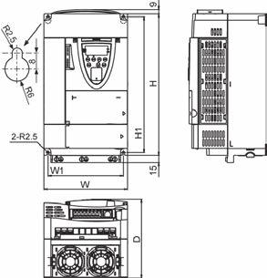
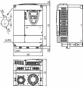
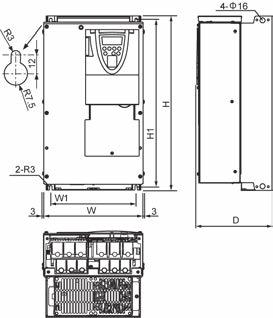
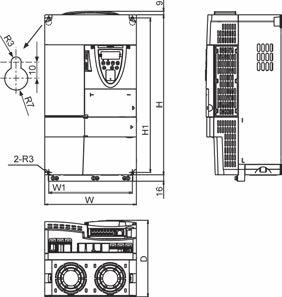
308 E Outline drawing (Installation dimension) (Installation dimension) (Installation dimension) (Installation dimension) Fig. A Fig. B (Installation dimension) (Installation dimension) (Installation dimension) (Installation dimension) Fig. C Fig.D 12 (Installation dimension) (Installation dimension) (Installation dimension) (Installation dimension) Fig. E Fig. F L-6
Instruction Manual. The new high-performance inverter VF-AS1. 200V class kW 400V class kW
 Safety precautions Introduction I II Contents Instruction Manual The new high-performance inverter TOSVERT TM 200V class 0.4 75kW 400V class 0.75 500kW VF-AS1 NOTICE 1.Make sure that this instruction manual
Instruction Manual. The new high-performance inverter VF-AS1. 200V class kW 400V class kW
 Safety precautions Introduction I II Contents Instruction Manual The new high-performance inverter TOSVERT TM VF-AS1 200V class 0.475kW 400V class 0.75500kW NOTICE 1.Make sure that this instruction manual
Instruction Manual. 200V class kW 400V class kW
 Safety precautions Introduction I II Contents Instruction Manual The new high-performance inverter TOSVERT TM 200V class 0.4 75kW 400V class 0.75 500kW VF-AS1 NOTICE 1.Make sure that this instruction manual
6.9 Jump frequency - Avoiding frequency resonance
 E581595.9 Jump frequency - Avoiding frequency resonance : Jump frequency : Jumping width Function Resonance due to the natural frequency of the mechanical system can be avoided by jumping the resonant
13. Before making a service call Trip information and remedies
 . Before making a service call Trip information and remedies.1 Trip causes/warnings and remedies When a problem arises, diagnose it in accordance with the following table. If it is found that replacement
TOSVERT TM VF-nC3 Parameter List
 TOSVERT TM VF-nC Parameter List E658664 - Setting information * Please fill it in if necessary. Item Content Item Content Setting date / person Customer Application Application model Motor manufacturer
VFS11 Parameter List for up to CPU version 105
 E65824 VFS Parameter List for up to CPU version 5 Setting Date Customer End user Application Application No/Serial No Inverter s Type-Form Quantity Inverter s Serial No Motor s capacity If user s value
efesotomasyon.com -Toshiba inverter,drive,servo,plc TOSVERT VF-AS1/PS1 * The data given in this manual are subject to change without notice.
 E65812956 TOSVERT VF-AS1/PS1 Option Instruction Manual DEV002Z-1 NOTICE 1. Make sure that this instruction manual is delivered to the end user of the DeviceNet option for the VF-AS1/PS1. 2. Read this manual
ADJUSTABLE SPEED DRIVES VF-S11 Sords Electric
 ADJUSTABLE SPEED DRIVES VF-S11 The Next Generation of Micro Inverters is Here. The S11 provides maximum torque with precise speed control. It features an easy-to-use, quiet and compact design. In addition,
ADJUSTABLE SPEED DRIVES. AS1 Drive
 ADJUSTABLE SPEED DRIVES AS1 Drive Toshiba s New ASD Product Line The AS1 drive builds on Toshiba s history of supplying powerful, reliable, and versatile drives. We have combined our best drive features
[ 4 ] Using pulse train input (F01 = 12)
![[ 4 ] Using pulse train input (F01 = 12)](/thumbs/90/102625444.jpg "[ 4 ] Using pulse train input (F01 = 12)") [ 4 ] Using pulse train input (F01 = 12) Selecting the pulse train input format (d59) A pulse train in the format selected by the function code d59 can give a frequency command to the inverter. Three types
[ 4 ] Using pulse train input (F01 = 12) Selecting the pulse train input format (d59) A pulse train in the format selected by the function code d59 can give a frequency command to the inverter. Three types
TOSVERT VF-PS1 series Metasys N2 option unit Instruction Manual MTS001Z
 TOSVERT VF-PS1 series Metasys N2 option unit Instruction Manual MTS001Z NOTICE 1. Make sure that this instruction manual is delivered to the end user of Metasys N2 option unit. 2. Read this manual before
TOSVERT VF-PS1 series APOGEE FLN option unit Instruction Manual APG001Z
 TOSVERT VF-PS1 series APOGEE FLN option unit Instruction Manual APG001Z NOTICE 1. Make sure that this instruction manual is delivered to the end user of APOGEE FLN option unit. 2. Read this manual before
VFS9 Parameter List for Version110 or later
 VFS9 Parameter List for Version110 or later Setting Date Customer End user Application Application /Serial Inverter s Type-Form Quantity Inverter s Serial Motor s capacity If user s value is same as shipping
TOSVERT VF-PS1 series BACnet option unit Instruction Manual BCN001Z
 TOSVERT VF-PS1 series BACnet option unit Instruction Manual BCN001Z NOTICE 1. Make sure that this instruction manual is delivered to the end user of BACnet Option unit. 2. Read this manual before installing
AV-300i Specifications. Saftronics Inc. PC10 Product Specifications PC10. Mini Vector AC Drive
 Saftronics Inc. www.saftronics.com TM AV-300i Specifications PC10 Product Specifications PC10 Mini Vector AC Drive 1 (1) T hree-phas e 230V input Drive Hp 1/8 1/4 1/2 1 2 3 5 7.5 10 Nominal applicable
VFD - D700 Series Specifications. The latest low-cost variable speed control solution for centrifugal pumps.
 VFD - D700 Series Specifications The latest low-cost variable speed control solution for centrifugal pumps. Built-in PID Control to maintain pressure, flow, measured value, and much more 125% overload
For 3-phase induction motors. Instruction Manual VF-S11. < Simplified manual > 3-phase 500V class phase 600V class 0.75
 Safety precautions Contents I Industrial Inverter For 3-phase induction motors Instruction Manual TOSVERT TM VF-S11 < Simplified manual > 1-phase 240V class 0.2 3-phase 240V class 0.4 3-phase 500V class
SYSDRIVE 3G3HV Inverter Models The following 200- and 400-V class 3G3HV Inverter models are available.
 Function The 3G3HV High-capacity General-purpose Inverter is an easy-to-use inverter that has advanced features, such as PID control and energy-saving operations. SYSDRIVE 3G3HV Inverter Models The following
Before you operate the inverter, the parameters that you must first program are the basic parameters.
 . Main parameters Before you operate the inverter, the parameters that you must first program are the basic parameters..1 Searching for changes using the history function () : History function History
VF-nC1 Adjustable Speed Drive Engineering Specification
 PART 1 - GENERAL 1.0 Scope This specification shall cover Toshiba VF-nC1 AC Variable Frequency Drives, 6 pulse for 100V single-phase 0.1 to 0.75kW, 200V single-phase 0.2 to 2.2kW and 200V threephase 0.1
Index 2. G Gain settings 4 31 Glossary of terms A 2 Grommets 2 13
 Index A A Group functions 3 9 AC reactors 5 3 Acceleration 1 15, 3 8 characteristic curves 3 26 second function 3 24 two-stage 4 19 Acceleration stop function 3 21 Access levels 3 5, 3 36, 4 25 Access
Multi-function, Compact Inverters. 3G3MV Series
 Multi-function, Compact Inverters 3G3MV Series There has been a great demand for inverters with more functions and easier motor control than conventional i OMRON's powerful, compact 3G3MV Series with versat
General-Purpose AC Servo. MELSERVO-JE Servo amplifier INSTRUCTION MANUAL (TROUBLE SHOOTING)
") General-Purpose AC Servo MELSERVO-JE Servo amplifier INSTRUCTION MANUAL (TROUBLE SHOOTING) D Safety Instructions Please read the instructions carefully before using the equipment. To use the equipment
General-Purpose AC Servo MELSERVO-JE Servo amplifier INSTRUCTION MANUAL (TROUBLE SHOOTING) D Safety Instructions Please read the instructions carefully before using the equipment. To use the equipment
ADJUSTABLE SPEED DRIVES FS1
 ADJUSTABLE SPEED DRIVES FS1 Now Available With LonWorks BACnet & MetasysN2 FS1 Model FLA & Dimensions (in.)/ Weight (lbs.) VOLTAGE HP MODEL NUMBER FLA FRAME Dimensions (in.) SHIPPING H W D WEIGHT (lbs.)
THYFREC-VT230S 200V System 0.4 to 90kW 400V System 0.4 to 370kW INSTRUCTION MANUAL
 MEIDEN AC SPEED CONTROL EQUIPMENT THYFREC-VT230S 200V System 0.4 to 90kW 400V System 0.4 to 370kW INSTRUCTION MANUAL NOTICE 1. Read this manual thoroughly before using the VT230S, and store in a safe place
Operating Instructions
 4XH35QB151210 Small General Frequency Converter Operating Instructions 220V 0.75KW 5.5KW 400V 0.75KW 15KW Please read the instruction carefully and understand the contents so that it can be installed and
General-Purpose AC Servo. MELSERVO-JE Servo amplifier INSTRUCTION MANUAL (TROUBLE SHOOTING)
") General-Purpose AC Servo MELSERVO-JE Servo amplifier INSTRUCTION MANUAL (TROUBLE SHOOTING) F Safety Instructions Please read the instructions carefully before using the equipment. To use the equipment
General-Purpose AC Servo MELSERVO-JE Servo amplifier INSTRUCTION MANUAL (TROUBLE SHOOTING) F Safety Instructions Please read the instructions carefully before using the equipment. To use the equipment
S11 Adjustable Speed Drive Engineering Specification
 PART 1 - GENERAL 1.0 Scope This specification shall cover Toshiba S11 AC Variable Frequency Drives, 6 pulse for 3- phase 200-240VAC, 380-500VAC and single phase 200V to 240VAC. 1.1 References A. National
Fan and Pump AC Inverter
 Fan and Pump AC Inverter Key Features for Fan and Pump Applications PID and Auto Energy Saving Functions. Input Phase Loss and Output Phase Loss Protection. LCD Keypad can be used to copy parameter settings
(For 3-phase induction motors) Instruction Manual VF-S11. < Simplified manual >
 Instruction Manual VF-S11. < Simplified manual >") Safety precautions I Industrial Inverter (For 3-phase induction motors) Instruction Manual TOSVERT TM VF-S11 < Simplified manual > 1-phase 240V class 0.2 to 2.2kW 3-phase 240V class 0.4 to 15kW 3-phase
Safety precautions I Industrial Inverter (For 3-phase induction motors) Instruction Manual TOSVERT TM VF-S11 < Simplified manual > 1-phase 240V class 0.2 to 2.2kW 3-phase 240V class 0.4 to 15kW 3-phase
Foreword Thank you for purchasing the general-purpose VF series inverter produced by Panasonic Electric Works Automation Controls (Shanghai) Co., Ltd.
 Co., Ltd.") Inverter VF Instruction Manual [Support model] Three phase 4V (.75kW3.7kW) Read this manual carefully before attempting to operate the inverter and store it for further reference. 8A3 645 7 2 Foreword
Inverter VF Instruction Manual [Support model] Three phase 4V (.75kW3.7kW) Read this manual carefully before attempting to operate the inverter and store it for further reference. 8A3 645 7 2 Foreword
General-Purpose AC Servo. MELSERVO-JE Servo amplifier INSTRUCTION MANUAL (TROUBLE SHOOTING)
") General-Purpose AC Servo MELSERVO-JE Servo amplifier INSTRUCTION MANUAL (TROUBLE SHOOTING) B Safety Instructions Please read the instructions carefully before using the equipment. To use the equipment
General-Purpose AC Servo MELSERVO-JE Servo amplifier INSTRUCTION MANUAL (TROUBLE SHOOTING) B Safety Instructions Please read the instructions carefully before using the equipment. To use the equipment
Industrial Inverter. (For 3-phase induction motors) Instruction Manual. <Detailed manual>
 Instruction Manual. <Detailed manual>") Safety precautions I Industrial Inverter (For 3-phase induction motors) Instruction Manual 3-phase 24V class.4 to 15kW 1-phase 24V class.2 to 2.2kW 3-phase 5V class.4 to 15kW NOTICE 1.
Safety precautions I Industrial Inverter (For 3-phase induction motors) Instruction Manual 3-phase 24V class.4 to 15kW 1-phase 24V class.2 to 2.2kW 3-phase 5V class.4 to 15kW NOTICE 1.
Instruction Manual. The new generation high-performance inverter
 Safety precautions Preface I II Contents Instruction Manual The new generation high-performance inverter TM TOSVERT VF-A7 200V class 0.4 90kW 400V class 0.75280kW Read this section first Connection Operating
Cat. No. I528-E1-2 USER S MANUAL SYSDRIVE 3G3JV. Compact Simplified Inverters
 Cat. No. I528-E1-2 USER S MANUAL SYSDRIVE 3G3JV Compact Simplified Inverters Thank you for choosing this SYSDRIVE 3G3JV-series product. Proper use and handling of the product will ensure proper product
E3 Adjustable Speed Drive Engineering Specification
 E3 Adjustable Speed Drive Engineering Specification PART 1 - GENERAL 1.0 Scope This specification shall cover Toshiba E3 AC Variable Frequency Drives, 6 pulse for 230V and 460V. 1.1 References A. National
Industrial Inverter. For 3-phase induction motors. Instruction Manual. <Detailed manual>
 Safety precautions Introduction I II Industrial Inverter For 3-phase induction motors Instruction Manual 1-phase 120V class 0.1 to 0.75kW 1-phase 240V class 0.1 to 2.2kW 3-phase 240V
High performance multifunction quiet inverter INSTRUCTION MANUAL. SBT-0.75K/1.5K to SBT 22K/30K for general industry, fan and pump SBT-30K to 55K
 High performance multifunction quiet inverter VVVF Inverter INSTRUCTION MANUAL 200 V systems SBT-0.75K/1.5K to SBT 22K/30K for general industry, fan and pump SBT-30K to 55K 400 V systems SHF-1.5K to SHF-250K
FREQUENCY INVERTER VFR-013 QUICK START GUIDE
 FREQUENCY INVERTER VFR-013 QUICK START GUIDE Inoréa Automation & Industry 9 rue du Lugan 33130 BEGLES www.inorea.com Table of contents 1. PEOPLE SAFETY... 3 2. MATERIAL SAFETY... 3 3. NAME PLATE... 4 a.
SAFETY INSTRUCTIONS WARNING
 Important User Information Thank you for purchasing LS Variable Frequency Drives! SAFETY INSTRUCTIONS Always follow safety instructions to prevent accidents and potential hazards from occurring. In this
Manual Overview...1 2
 GETTING STARTED CHAPTER 1 Contents of this Chapter... Manual Overview.....................................1 2 Overview of this Publication..................................1 2 Who Should Read This Manual...............................1
Ambient Conditions Storage Conditions Installation Minimum Clearances and Air Flow...2 3
 CHAPTER INSTALLATION 2 AND WIRING Contents of this Chapter... Ambient Conditions..............................2 2 Storage Conditions...............................2 2 Installation.....................................2
CHAPTER MAINTENANCE AND TROUBLESHOOTING. In This Chapter... Maintenance and Inspection Troubleshooting...6 3
 CHAPTER MAINTENANCE AND 6 TROUBLESHOOTING In This Chapter... Maintenance and Inspection.................6 2 Monthly Inspection:..................................6 2 Annual Inspection....................................6
FUJI Inverter. Standard Specifications
 FUJI Inverter o Standard Specifications Norminal applied motor The rated output of a general-purpose motor, stated in kw. That is used as a standard motor. Rated capacity The rating of an output capacity,
INVERTER INSTRUCTION MANUAL. 16 bit digital input function. Plug-in option FR-A7AX PRE-OPERATION INSTRUCTIONS INSTALLATION AND WIRING
 INVERTER Plug-in option FR-A7AX INSTRUCTION MANUAL 16 bit digital input function PRE-OPERATION INSTRUCTIONS INSTALLATION AND WIRING CONNECTION DIAGRAM AND TERMINAL PARAMETERS 1 2 3 4 Thank you for choosing
This operation manual is intended for users with basic knowledge of electricity and electric devices.
 This operation manual is intended for users with basic knowledge of electricity and electric devices. Safety Information Safety Information Read and follow all safety instructions in this manual precisely
GS1 Parameter Summary Detailed Parameter Listings...4 9
 CHAPTER AC DRIVE 4 PARAMETERS Contents of this Chapter... GS1 Parameter Summary...............................4 2 Detailed Parameter Listings..............................4 9 Motor Parameters.........................................4
TOSVERT VF-AS1 E Parameter List (V154)
") TOSVERT VFAS1 Parameter List (V154) VFAS1 Parameter List (V154) Setting date Customer End user Application Application No/Serial No Inverter s TypeForm Quantity Inverter s Serial No Motor s If user s setting
TOSVERT VFAS1 Parameter List (V154) VFAS1 Parameter List (V154) Setting date Customer End user Application Application No/Serial No Inverter s TypeForm Quantity Inverter s Serial No Motor s If user s setting
General-Purpose AC Servo. MELSERVO-J4 Servo amplifier INSTRUCTION MANUAL (TROUBLE SHOOTING)
") General-Purpose AC Servo MELSERVO-J4 Servo amplifier INSTRUCTION MANUAL (TROUBLE SHOOTING) K Safety Instructions Please read the instructions carefully before using the equipment. To use the equipment
General-Purpose AC Servo MELSERVO-J4 Servo amplifier INSTRUCTION MANUAL (TROUBLE SHOOTING) K Safety Instructions Please read the instructions carefully before using the equipment. To use the equipment
α α Retry count clear Alarm reset Active End of retry S-curve time during accelerati on H04: (Count) setting S curve time during decelerati on
 setting S curve time during decelerati on") Upon success of retry Alarm Occurrence Disappearance Time S-curve acceleration/deceleration To reduce the shock of the mechanical system, the change in the output frequency is made smooth when the frequency
Upon success of retry Alarm Occurrence Disappearance Time S-curve acceleration/deceleration To reduce the shock of the mechanical system, the change in the output frequency is made smooth when the frequency
Digital Interface Option "OPC-E1-DIO"
 Instruction Manual Digital Interface Option "OPC-E1-DIO" Thank you for purchasing our digital interface option. Read through this instruction manual and be familiar with the digital interface option before
TH450A-T TH550A-T THP550-T/TS3000
 0 TH450A-T TH550A-T THP550-T/TS3000 INSTRUCTION MANUAL CEILING TYPE (OVERHEAD TRAVELING TYPE) INDUSTRIAL ROBOT SPECIFICATIONS Notice 1. Make sure that this instruction manual is delivered to the final
ROLL TO ROLL FUNCTION MANUAL FR-A (0.4K)-04750(90K)-R2R FR-A (0.4K)-06830(280K)-R2R FR-A (315K)-12120(500K)-R2R
-04750(90K)-R2R FR-A (0.4K)-06830(280K)-R2R FR-A (315K)-12120(500K)-R2R") INVERTER ROLL TO ROLL FUNCTION MANUAL FR-A820-00046(0.4K)-04750(90K)-R2R FR-A840-00023(0.4K)-06830(280K)-R2R FR-A842-07700(315K)-12120(500K)-R2R Roll to Roll Function The FR-A800-R2R inverter has dedicated
INVERTER ROLL TO ROLL FUNCTION MANUAL FR-A820-00046(0.4K)-04750(90K)-R2R FR-A840-00023(0.4K)-06830(280K)-R2R FR-A842-07700(315K)-12120(500K)-R2R Roll to Roll Function The FR-A800-R2R inverter has dedicated
Troubleshooting and Maintenance
 6 In This Chapter... page... 2 Monitoring Trip Events, History, & Conditions.. 5 Restoring Factory Default Settings... 8 Maintenance and Inspection... 9 Warranty... 16 6 2 Safety Messages Please read the
INSTRUCTION MANUAL (BASIC)
") TRANSISTORIZED INVERTER FR-S500 INSTRUCTION MANUAL (BASIC) FR-S540E-0.4K to 3.7K-EC FR-S520SE-0.2K to 1.5K-EC Thank you for choosing this Mitsubishi transistorized inverter. If this is the first time for
TRANSISTORIZED INVERTER FR-S500 INSTRUCTION MANUAL (BASIC) FR-S540E-0.4K to 3.7K-EC FR-S520SE-0.2K to 1.5K-EC Thank you for choosing this Mitsubishi transistorized inverter. If this is the first time for
GS S. Compact Space Ve VFD. Frequency and .5 5
 GS S Compact Space Ve VFD Frequency and.55.55 8 Thank you for purchasing CERUS Variable Frequency Drives! SAFETY INSTRUCTIONS Always follow safety instructions to prevent accidents and potential hazards
HPVFP High Performance Full Function Vector Frequency Inverter
 Advanced User Manual HPVFP High Performance Full Function Vector Frequency Inverter HP VER 1.00 1. HPVFP Parameter Set Overview...3 1.1. About this section...3 1.2. Parameter Structure Overview...3 1.3.
Dynamo Brushless DC Motor and GreenDriveTM Manual
 Dynamo Brushless DC Motor and GreenDriveTM Manual This manual was developed as a guide for use by FIRST Robotics Teams using Controller Part Number 840205-000 in conjunction with the Nidec Dynamo BLDC
USER S MANUAL. Customised to your machine Model: RX 200 V Class Three-Phase Input 0.4 to 55 kw 400 V Class Three-Phase Input 0.
 Cat. No. I560-E2-03A-X RX Customised to your machine Model: RX 200 V Class Three-Phase Input 0. to 55 kw 00 V Class Three-Phase Input 0. to 132 kw USER S MANUAL Introduction Introduction Thank you for
CHAPTER AC DRIVE PARAMETERS. In This Chapter...
 CHAPTER AC DRIVE 4 PARAMETERS In This Chapter... GS2 Parameter Summary....................4 2 Detailed Parameter Listings.................4 11 Motor Parameters........................4 11 Ramp Parameters.........................4
Tube Facing Tool.
 www.swagelok.com Tube Facing Tool This manual contains important information for the safe and effective operation of the Swagelok TF72 series tube facing tool. Users should read and understand its contents
USER S MANUAL. OMNUC U SERIES MODELS R88M-U (AC Servo Motors) MODELS R88D-UT (AC Servo Drivers) AC SERVO MOTORS/DRIVERS (1 to 5 kw)
 MODELS R88D-UT (AC Servo Drivers) AC SERVO MOTORS/DRIVERS (1 to 5 kw)") USER S MANUAL OMNUC U SERIES MODELS R88M-U (AC Servo Motors) MODELS R88D-UT (AC Servo Drivers) AC SERVO MOTORS/DRIVERS (1 to 5 kw) Thank you for choosing this OMNUC U-series product. Proper use and handling
USER S MANUAL OMNUC U SERIES MODELS R88M-U (AC Servo Motors) MODELS R88D-UT (AC Servo Drivers) AC SERVO MOTORS/DRIVERS (1 to 5 kw) Thank you for choosing this OMNUC U-series product. Proper use and handling
INSTALLATION AND OPERATION MANUAL IODA INPUT/OUTPUT MULTI-FUNCTION BOARD (Part No. 9668)
") INSTALLATION AND OPERATION MANUAL IODA INPUT/OUTPUT MULTI-FUNCTION BOARD (Part No. 9668) Use with Models KBDA-24D, 27D, 29, 45, 48 See Safety Warning, on page 4. RoHS The information contained in this
INSTALLATION AND OPERATION MANUAL IODA INPUT/OUTPUT MULTI-FUNCTION BOARD (Part No. 9668) Use with Models KBDA-24D, 27D, 29, 45, 48 See Safety Warning, on page 4. RoHS The information contained in this
Chapter 8 Troubleshooting
 Chapter -1 Error Processing... -1 Preliminary Checks When a Problem Occurs...-1 Precautions When...-2 Replacing the Servomotor and Servo Drive...-2-2 Alarm Table... -3-3... -7 Error Diagnosis Using the
TS-700/1000 INVERTER Instruction Manual
 TS-700/1000 INVERTER Instruction Manual TS-700/1000 Instruction Manual Index 1. Safety Guidelines... 1 2. Introduction... 1 2.1 Features... 1 2.2 Main Specification... 2 3. User Interface... 2 3.1 Front
BC145 SIGNAL ISOLATOR BOARD
 BC145 SIGNAL ISOLATOR BOARD 4/17 Installation & Operating Manual MN1373 Any trademarks used in this manual are the property of their respective owners. Important: Be sure to check www.baldor.com to download
AC SPEED CONTROL EQUIPMENT. VAT2000 3ph 200V-230V System 0.4 to 45kW 3ph 380V-460V System 0.4 to 370kW INSTRUCTION MANUAL
 GE Power Controls AC SPEED CONTROL EQUIPMENT VAT2000 3ph 200V-230V System 0.4 to 45kW 3ph 380V-460V System 0.4 to 370kW INSTRUCTION MANUAL --------------------------------- NOTICE ------------------------------------------
Invertek Optidrive E3 Frequency Inverter (IP20, 3ph output) Easy Start Guide
 Easy Start Guide") Invertek Optidrive E3 Frequency Inverter (IP20, 3ph output) Easy Start Guide The Invertek Optidrive E3 Frequency Inverter range is available to order from inverterdrive.com This guide is intended to complement
Invertek Optidrive E3 Frequency Inverter (IP20, 3ph output) Easy Start Guide The Invertek Optidrive E3 Frequency Inverter range is available to order from inverterdrive.com This guide is intended to complement
Cat. No. I013-E1-4 USER S MANUAL SYSDRIVE 3G3EV. (Multi-function Models) Compact Low-noise Inverter
 Compact Low-noise Inverter") Cat. No. I013-E1-4 USER S MANUAL SYSDRIVE 3G3EV (Multi-function Models) Compact Low-noise Inverter Thank you for choosing this SYSDRIVE 3G3EV-series product. Proper use and handling of the product will
Cat. No. I013-E1-4 USER S MANUAL SYSDRIVE 3G3EV (Multi-function Models) Compact Low-noise Inverter Thank you for choosing this SYSDRIVE 3G3EV-series product. Proper use and handling of the product will
Be sure to hand over this instruction manual to customers.
 M2X Series Inverter for 3-phase Induction Motor Speed Control INSTRUCTION MANUAL Be sure to hand over this instruction manual to customers. Thank you for purchasing Panasonic Inverter. To ensure proper
Troubleshooting 12. This section explains the items to check when problems occur, and troubleshooting by the use of error displays or operation state.
 Troubleshooting 12 This section explains the items to check when problems occur, and troubleshooting by the use of error displays or operation state. 12-1 Actions for Problems..........................................
EMHEATER. EM11 Series Frequency Inverter. User s Manual. China EM Technology Limited. Address:
 EM11 Series Inverter User s Manual User s Manual EMHEATER EM11 Series Frequency Inverter China EM Technology Limited Address: No.80, Baomin 2 road, Xixiang, Bao'an District,Shenzhen,China Phone: 86-0755-29985851
SYSDRIVE 3G3XV Inverter 3G3XV- -EV2 Operation Manual
 SYSDRIVE 3G3XV Inverter 3G3XV- -EV2 Operation Manual Revised November 1997 iv Notice: OMRON products are manufactured for use according to proper procedures by a qualified operator and only for the purposes
MDS-CH-SP PLG Adjustment(BNP-B H)
") MELDAS Series MDS-CH-SP PLG Adjustment(BNP-B8827-016H) USA-99671-024* MITSUBISHI ELECTRIC AUTOMATION USA List of Revisions Rev Date of Revision Detail Author * 05/3/04 First Edition Created TSS AC SPINDLE
MELDAS Series MDS-CH-SP PLG Adjustment(BNP-B8827-016H) USA-99671-024* MITSUBISHI ELECTRIC AUTOMATION USA List of Revisions Rev Date of Revision Detail Author * 05/3/04 First Edition Created TSS AC SPINDLE
L100-M Series Inverters
 L100-M Series Inverters Addendum to L100 Series Inverter Instruction Manual In This Addendum... page Getting Started... 3 Inverter Mounting and Installation... 10 Configuring Drive Parameters... 15 Operations
Multifunction Keypad OP-KP-LCD. Multi-function Keypad with LCD & LED display for programming IMO Jaguar Inverters.
 Instruction Manual Multifunction Keypad OP-KP-LCD Multi-function Keypad with LCD & LED display for programming IMO Jaguar Inverters. Thank you for purchasing our JAGUAR series of inverters. This product
D SERIES EM16 IP 20 / NEMA 1 & IP 66 / NEMA 4X COMPACT VECTOR CONTROL DRIVE EM 16 COMPACT VECTOR CONTROL DRIVE
 D SERIES EM16 IP 20 / NEMA 1 & IP 66 / NEMA 4X COMPACT VECTOR CONTROL DRIVE EM 16 COMPACT VECTOR CONTROL DRIVE 1 2 SERIES 1 2 pag. 4 pag. 5 Applications Model identification 3 pag. 5 4 pag. 6 Capacity
This section is specifically about safety matters
 6 4 ) 1 6 4 1 -, 1 8-4 6-4 1 6 4 7 + 6 1 ) 7 ) 4 ) 6 1-6 6-4. 4. 0 J E? A Thank you for choosing this Mitsubishi transistorized Inverter option. This instruction manual gives handling information and precautions
The new Yaskawa Varispeed G7 Inverter
 The new Yaskawa Varispeed G7 Inverter Unique new 3-level PWM flux vector Constant or variable torque applications control method 0.4 kw to 300 kw power range Exceptional low speed/high torque control Quick
General-Purpose AC Servo. MELSERVO-J4 Servo amplifier INSTRUCTION MANUAL (TROUBLE SHOOTING)
") General-Purpose AC Servo MELSERVO-J4 Servo amplifier INSTRUCTION MANUAL (TROUBLE SHOOTING) N Safety Instructions Please read the instructions carefully before using the equipment. To use the equipment
General-Purpose AC Servo MELSERVO-J4 Servo amplifier INSTRUCTION MANUAL (TROUBLE SHOOTING) N Safety Instructions Please read the instructions carefully before using the equipment. To use the equipment
This section is specifically about safety matters
 6 4 ) 5 1 5 6 4 1 -, 1 8-4 6-4 1 5 6 4 7 + 6 1 ) 7 ) 5 2 - -,, - 6 - + 6 4. 4. 2 J E? A Thank you for choosing this Mitsubishi transistorized Inverter option. This instruction manual gives handling information
User manual. Altivar 21. Variable speed drives for asynchronous motors
 User manual Altivar 21 Variable speed drives for asynchronous motors I. Safety precautions The items described in these instructions and on the inverter itself are very important so that you can use the
CD770 DIGITAL MULTIMETER INSTRUCTION MANUAL
 CD770 DIGITAL MULTIMETER INSTRUCTION MANUAL Table of Contents 1 SAFETY PRECAUTIONS Before use, read the following safety precautions.- 1-1 Explanation of Warning Symbols 001 1-2 Warning Messages for Safe
Preface. Notes. Thank you for purchasing the VTP8 series AC drive.
 Preface Thank you for purchasing the VTP8 series AC drive. The VTP8 series AC drive is a general-purpose high-performance current vector control AC drive. It can implement the control of asynchronous motor.
About this Manual: Chapter 1 provides a summary of the Servo System and all gains used for the Servo System loops.
 About this Manual: This guide describes the installation and startup procedures of the Servo System so that it can be efficiently put in actual operation in a short time. This guide provides detailed descriptions
High Frequency Sinewave Guardian TM Filter
 High Frequency Sinewave Guardian TM Filter 380V 480V TECHNICAL REFERENCE MANUAL FORM: SHF-TRM-E REL. April 2015 REV. 001 2015 MTE Corporation Caution Prior to start up; confirm the drive operation mode
USER MANUAL -Installation and Programming Instructions-
 15P0073B1 SERIES M VARIABLE FREQUENCY DRIVE FULL DIGITAL INVERTER USER MANUAL -Installation and Programming Instructions- Issued on 14/05/09 R.02 SW Ver. EU2.2 English This manual is integrant and essential
IC5 Series. LG Variable Frequency Drive 1/2-3 HP (230V) LG Industrial SystemsG. Installation, Operation and Maintenance Instruction
 LG Industrial SystemsG. Installation, Operation and Maintenance Instruction") LG Variable Frequency Drive IC5 Series GGGGGGG G G G G G G G G GGGGGGG 1/2-3 HP (230V) GGGGGGGGGGGGGGGGGGGGGGGG G G G G GGGGGGG G G Installation, Operation and Maintenance Instruction G G G G G G G G G
LG Variable Frequency Drive IC5 Series GGGGGGG G G G G G G G G GGGGGGG 1/2-3 HP (230V) GGGGGGGGGGGGGGGGGGGGGGGG G G G G GGGGGGG G G Installation, Operation and Maintenance Instruction G G G G G G G G G
VECTOR INVERTER -INSTRUCTION MANUAL- 16-BIT DIGITAL INPUT FR-V5AH
 VECTOR INVERTER -INSTRUCTION MANUAL- 16-BIT DIGITAL INPUT FR-V5AH Thank you for choosing the Mitsubishi vector inverter option unit. This instruction manual gives handling information and precautions for
G+ Mini Transition Guide. Product Transition Guide P3 Series 2 to G+ Mini
 Transition Guide Product Transition Guide to Rev: Page Intentionally Left Blank Transition Guide September 2008 Page 2 of 24 Table of Contents 1.1 Overview...4 1.2 Drive Replacement Checklist...4 1.3 Ratings
Compact Inverter User's Manual
 Compact Inverter User's Manual Copyright 2002-2007 Fuji Electric FA Components & Systems Co., Ltd. All rights reserved. No part of this publication may be reproduced or copied without prior written permission
User s Manual Before using the inverter, you need to read and save the safety instructions.
 User s Manual Before using the inverter, you need to read and save the safety instructions. SHI 400 / SHI 600 / SHI 1000 Pure Sine Wave Inverter The information presented in this document does not form
Instruction Manual. Designed for Elevating Machinery. Fuji Electric FA Components & Systems Co., Ltd.
 Instruction Manual Designed for Elevating Machinery Thank you for purchasing our FRENIC-Lift series of inverters. This product is designed to drive a three-phase induction motor and synchronous motor.
General Specifications FECA-TE /2010. Phone: Fax: Web:
 General Specifications FECA-TE-117 06/2010 1. Standard Specifications 1) Three-phase 230V series Output ratings Input ratings Braking Item Specifications Type (FRN C1S-2U) F12 F25 F50 001 002 003 005 Nominal
D.C. BRUSHLESS MOTORS DRIVE. BLD07-IT Service Manual
 D.C. BRUSHLESS MOTORS DRIVE BLD07-IT Service Manual INTECNO s.r.l. Via Caduti di Sabbiuno n. 9/E 40011 Anzola Emilia (BO) - Italy tel. 051.19985350 fax 051.19985360 www.intecno-srl.com INDEX Description
In the event of a failure, the inverter switches off and a fault code appears on the display.
 Issue 03/05 Faults and Alarms 5 Faults and Alarms 5.1 Fault messages In the event of a failure, the inverter switches off and a fault code appears on the display. NOTE To reset the fault code, one of three
3G3JX 200 V V V
 Cat. No. I558-E2-03 JX Compact and complete Model: 3G3JX 200 V Class Three-Phase Input 0.2 to 7.5 kw 200 V Class Single-Phase Input 0.2 to 2.2 kw 400 V Class Three-Phase Input 0.4 to 7.5 kw USER S MANUAL
Q9 ASD Installation and Operation Manual
 TOSHIBA Q9 ASD Installation and Operation Manual Q9 Adjustable Speed Drive Document Number: 59445-003 Date: April, 2010 Q9 ASD Installation and Operation Manual Document Number: 59445-003 Date: April,