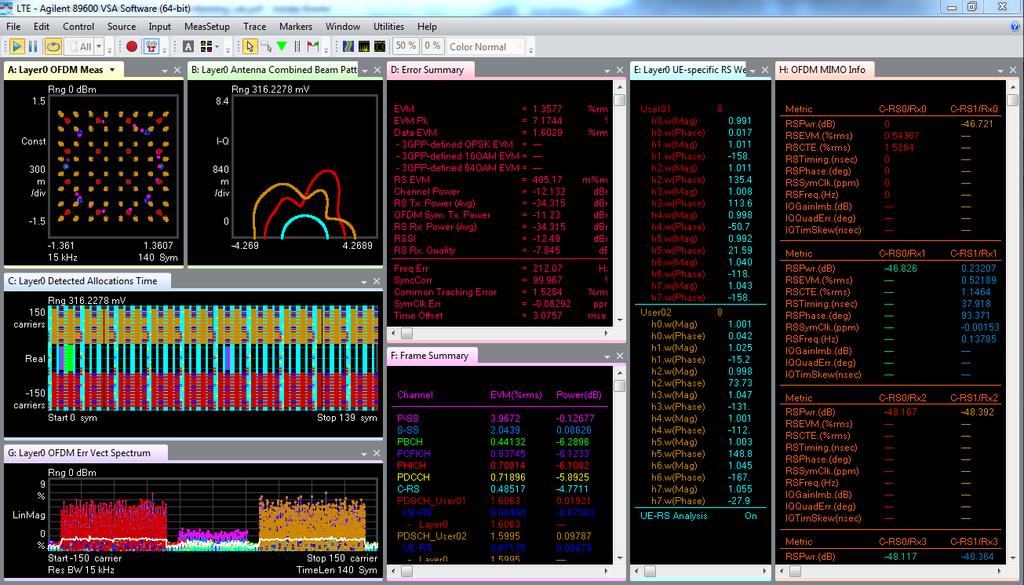
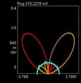
LTE and the Evolution to LTE-Advanced Fundamentals
|
|
|
- Leon Houston
- 5 years ago
- Views:
Transcription


1 LTE and the Evolution to LTE-Advanced Fundamentals Based on the 2 nd Edition book LTE and the Evolution to 4G Wireless Design and Measurement Challenges Presented by: Agilent Technologies
2 Agenda Introduction to LTE - Evolution and Motivation - Major features and requirements Air Interface Concepts - Frequency bands - OFDMA/SC-FDMA - Structure frame, slots, resource blocks - Physical signals and channels MIMO Concepts LTE-Advanced Major Features and Design Challenges - Carrier Aggregation - Enhanced Uplink Multiple Access (clustered SC-FDMA) - High Order MIMO - Other Study Items Question and Answer


 imode W-CDMA (FDD & TDD)")
 TD-SCDMA (China) EDGE")
 IS-136")

 cdma2000 (1x RTT)")
3 Cellular Evolution Technology evolution Market evolution W-LAN Increasing efficiency, bandwidth and data rates 2G 2.5G 3G 3.5G 3.9G/ 4G 4G / IMT- Advanced PDC (Japan) imode W-CDMA (FDD & TDD) HSDPA HSUPA HSPA+ / E-HSPA HSCSD GSM (Europe) TD-SCDMA (China) EDGE Evolution GPRS LTE (R8/9 FDD & TDD) LTE-Advanced (R10 & beyond) IS-136 (US TDMA) E-GPRS (EDGE) 1x EV-DO 0 A B e (Mobile WiMAX) IS-95A (US CDMA) IS-95B (US CDMA) cdma2000 (1x RTT) m / WiMAX2 WirelessMAN-Advanced d (Fixed WiMAX) WiBRO (Korea) b a/g h n ac ad
4 3GPP UMTS Long Term Evolution Release Stage 3: Core specs complete Main feature of Release Rel-99 March 2000 UMTS 3.84 Mcps (W-CDMA FDD & TDD) Rel-4 March Mcps TDD (aka TD-SCDMA) Rel-5 June 2002 HSDPA Rel-6 March 2005 HSUPA (E-DCH) Rel-7 Dec 2007 HSPA+ (64QAM DL, MIMO, 16QAM UL). LTE & SAE Feasibility Study, Edge Evolution Rel-8 Dec 2008 LTE Work item OFDMA air interface SAE Work item New IP core network UMTS Femtocells, Dual Carrier HSDPA Rel-9 Dec 2009 Multi-standard Radio (MSR), Dual Carrier HSUPA, Dual Band HSDPA, SON, LTE Femtocells (HeNB) LTE-Advanced feasibility study, MBSFN Rel-10 March 2011 LTE-Advanced (4G) work item, CoMP Study Four carrier HSDPA Rel-11 Sept 2012 CoMP, edl MIMO, eca, MIMO OTA, HSUPA TxD & 64QAM MIMO, HSDPA 8C & 4x4 MIMO, MB MSR Rel-12 June -> Sept 2014 New carrier type, LTE-Direct, Active Antenna Systems, small cells Rel-13 Dec 2015 Just starting more CA

5 LTE Commercial Networks FDD & TDD

6 LTE-TDD Investment Worldwide
7 LTE Major Features Feature Access modes Channel BW 1RB = 12 subcarriers = 180 khz Transmission Scheme Modulation Formats MIMO Technology Peak Data Rates Bearer services Transmission Time Interval (TTI) Capability FDD & TDD 1.4 MHz 3 MHz 5 MHz 10 MHz 15 MHz 20 MHz 6 RB 15 RB 25 RB 50 RB 75 RB 100 RB Downlink: OFDMA (Orthogonal Frequency Division Multiple Access) Uplink: SC-FDMA (Single Carrier Frequency Division Multiple Access QPSK, 16QAM, 64QAM Downlink: Tx diversity, Rx diversity, Single-User MIMO (up to 4x4), beamforming Uplink: Multi-User MIMO Downlink: 300 Mbps (4x4 MIMO, 20 MHz, 64QAM) Uplink: 75 Mbps ( 20 MHz BW, 64QAM) Packet only no circuit switched voice or data services are supported voice must use VoIP 1 ms
8 Agenda Introduction to LTE - Evolution and Motivation - Major features and requirements Air Interface Concepts - Frequency bands - OFDMA/SC-FDMA - Structure frame, slots, resource blocks - Physical signals and channels MIMO Concepts LTE-Advanced Major Features and Design Challenges - Carrier Aggregation - Enhanced Uplink Multiple Access (clustered SC-FDMA) - High Order MIMO - Other Study Items Question and Answer
9 Frequency Bands Release Independent Release independent means that a band defined in a later release can be applied to an earlier release This significantly simplifies the specifications There are currently 42 frequency bands defined by 3GPP for LTE with more on the way in Release 12 FDD TDD Release (excl. 15,16*) Release Release Release Release 12 30, 31, plus * Bands 15 and 16 are specified by ETSI only for use in Europe
10 LTE FDD Frequency Bands March 2014 Band Uplink MHz Downlink MHz Width Duplex Gap * * N/A Width Uplink Band Duplex spacing Gap Frequency Width Downlink Band There is a lot of overlap between band definitions for regional reasons The Duplex spacing varies from 30 MHz to 799 MHz The gap between downlink and uplink varies from 5 MHz to 680 MHz Narrow duplex spacing and gaps make it hard to design filters to prevent the transmitter spectral regrowth leaking into the receiver (self-blocking) Bands 13, 14, 20 and 24 have reversed uplink downlink frequencies Bands 15 and 16 are specified by ETSI only for use in Europe Band 29 restricted to E-UTRA operation when carrier aggregation is configured.
11 LTE TDD Frequency Bands March 2014 Band Uplink MHz Downlink MHz Width Width Transceive Band Frequency

12 Orthogonal Frequency Division Multiplexing Figure 1: Frequency-Time Representation of an OFDM Signal LTE provides QPSK, 16QAM, 64QAM as downlink modulation schemes Each sub-carrier carries a separate low-rate stream of data 15 khz subcarrier spacing Each sub-carrier is independently modulated Cyclic prefix is used as guard interval to minimize inter-symbol interference
13 OFDMA: The Basis for LTE s Downlink Transmission OFDM is already widely used in non-cellular technologies and was considered by ETSI for UMTS in 1998 CDMA was favored since OFDM requires large amounts of baseband processing which was not commercially viable at that time OFDMA advantages Almost completely resistant to multi-path due to very long symbols Optimum use of available spectrum and efficient receiver architecture Ideally suited to MIMO due to easy matching of transmit signals to the uncorrelated RF channels OFDMA disadvantages Sensitive to frequency errors and phase noise due to close subcarrier spacing Sensitive to Doppler shift which creates interference between subcarriers Pure OFDM creates high PAR which is why SC-FDMA is used on UL More complex than CDMA for handling inter-cell interference at cell edge
14 Why SC-FDMA for the Uplink? SC-FDMA is a new hybrid transmission scheme combining the low PAR single carrier methods with the frequency allocation flexibility and long symbol time of OFDMA DFT is first applied to block of N TX modulated symbols to transform them into frequency domain Sub-carrier mapping allows flexible allocation of signal to available sub-carriers SC-FDMA is sometimes referred to as Discrete Fourier Transform Spread OFDM = DFT- SOFDM Time domain Frequency domain Time domain Coded symbol rate= R DFT Sub-carrier Mapping IFFT CP insertion N TX symbols Size-N TX Size-N FFT TR Figure Transmitter structure for SC-FDMA.


15 Comparing OFDMA and SC-FDMA QPSK example using M=4 subcarriers 1, 1-1,-1-1, 1 1, -1 1,1 1, -1-1,1-1,-1-1,1 Q 1,1 Time I -1,-1 1,-1 V V CP CP f c 15 khz Frequency f c 60 khz Frequency OFDMA Data symbols occupy 15 khz for one OFDMA symbol period SC-FDMA Data symbols occupy M*15 khz for 1/M SC-FDMA symbol periods
16 OFDMA Signal Generation QPSK example using M=4 subcarriers One OFDMA symbol period Each of M subcarriers is encoded with one QPSK symbol M subcarriers can transmit M QPSK symbols in parallel -1,1-1,-1 Q 1,1 I 1,-1 1, , , f 0 (F cycles) f khz (F+1 cycles) f khz (F+2 cycles) The amplitude of the combined four subcarrier signal varies widely depending on the symbol data being transmitted 1, f khz (F+3 cycles) Peak created by transmitting four identical symbols Null created by transmitting four different symbols One symbol period With many subcarriers the waveform becomes Gaussian not sinusoidal
 +1-1 V(Q) One SC-FDMA symbol period One SC-FDMA symbol period Perform a DFT of length M and sample rate M/(symbol period) to create M FFT bins spaced by 15 khz V,Φ")
17 SC-FDMA Signal Generation QPSK example using M=4 subcarriers To transmit the sequence: 1, 1-1,-1-1, 1 1,-1 using SC-FDMA first create a time domain representation of the IQ baseband sequence -1,1-1,-1 Q 1,1 I 1, V(I) +1-1 V(Q) One SC-FDMA symbol period One SC-FDMA symbol period Perform a DFT of length M and sample rate M/(symbol period) to create M FFT bins spaced by 15 khz V,Φ Frequency Shift the M subcarriers to the desired allocation within the system bandwidth V,Φ Frequency Perform an IFFT to create a time domain signal of the frequency shifted original Insert the cyclic prefix between SC-FDMA symbols and transmit Important Note: The PAR is the same as the original QPSK data symbols

18 Complimentary Cumulative Distribution Function Gaussian 16 QAM SC-FDMA CCDF is several db below Gaussian reference line - what OFDMA would have given.
19 Physical Layer Definitions - Frame Structure Frame Structure type 1 (FDD) One slot = 0.5 ms FDD: Uplink and downlink are transmitted separately #0 #1 #2 #3. #18 #19 One subframe = 1ms One radio frame = 10 ms Transmission time interval is 1 subframe = 2 slots Subframe 0 Subframe 1 Subframe 9 Frame Structure type 2 (TDD) One half-frame = 5 ms 5ms switch-point periodicity: Subframe 0, 5 and DwPTS for downlink, Subframe 2, 5 and UpPTS for Uplink 10ms switch-point periodicity: Subframe 0, 5,7-9 and DwPTS for downlink, Subframe 2 and UpPTS for Uplink One radio frame = 10 ms One subframe = 1 ms For 5ms switch-point periodicity #0 #2 #3 #4 #5 #7 #8 #9 DwPTS, T(variable) UpPTS, T(variable) Guard period, T(variable) One slot = 0.5 ms For 10ms switch-point periodicity
20 TDD Downlink and Uplink Allocation 5ms switch-point periodicity Subframe 0, 5 and DwPTS for downlink, Subframe 2, 7 and UpPTS for uplink #0 #1 #2 #3 #4 #5 #6 #7 #8 #9 DwPTS GP UpPTS DwPTS GP UpPTS 10ms switch-point periodicity Subframe 0, 5-9 and DwPTS for downlink,subframe 2 and UpPTS for Uplink #0 #1 #2 #3 #4 #5 #6 #7 #8 #9 DwPTS GP UpPTS : downlink; :uplink DwPTS: Downlink Pilot Timeslot GP: Guard Period UpPTS: Uplink Pilot Timeslot
21 TDD Downlink and Uplink Switch-Points Depends on configuration #0 #1 #2 #3 #4 #5 #6 #7 #8 #9 DwPTS GP UpPTS DwPTS GP UpPTS Configuration Switchpoint periodicity Subframe number ms D S U U U D S U U U 1 5 ms D S U U D D S U U D 2 5 ms D S U D D D S U D D 3 10 ms D S U U U D D D D D 4 10 ms D S U U D D D D D D 5 10 ms D S U D D D D D D D 6 5 ms D S U U U D S U U D D: downlink; U: uplink S: Special subframe
22 Special Subframe Configuration DwPTS GP UpPTS Subframe 1 Special subframe New in 3GPP Rel 11 Special subframe config Normal Cyclic prefix length in OFDM symbols Extended Cyclic prefix length in OFDM symbols DwPTS GP UpPTS DwPTS GP UpPTS Golden Rule: the total length for DwPTS + GP + UpPTS = 1ms = 14 symbols in normal CP or 12 symbols in extended CP DwPTS: Downlink Pilot Signal carries PDCCH, P-SS, RS, PDSCH GP: Guard Period, separates between the UL and DL UpPTS: Uplink Pilot Signal carries PRACH, S-RS
23 Special Subframe Configuration DwPTS GP UpPTS Subframe 1 Special subframe Special subframe config Normal Cyclic prefix in DL and UL DwPTS GP UpPTS Max cell size km km km km km km km km km Golden Rule: the total length for DwPTS + GP+ UpPTS = 1ms = 14 symbols in normal CP or 12 symbols in extended CP DwPTS: Downlink Pilot Signal carries PDCCH, P-SS, RS, PDSCH GP: Guard Period, separates between the UL and DL UpPTS: Uplink Pilot Signal carries PRACH, S-RS
24 Slot Structure and Resource Block (RB) One downlink slot, T slot A Resource Element (RE) is the smallest unit in the physical layer and occupies one symbol in the time domain and one sub-carrier in the frequency domain. subcarriers DL N symb OFDM symbols : Resource Block (RB) RB x N sc DL N symb Resource Element (RE) (k, l) A Resource Block (RB) is basic scheduling unit. It contains: 7 symbols (1 slot) X 12 subcarriers for normal cyclic prefix or; 6 symbols (1 slot) X 12 subcarriers for extended cyclic prefix Minimum user allocation is 1 ms (2 slots) and 180 khz (12 subcarriers, 1RB). subcarriers Condition - Uplink N RB sc N UL symb Normal cyclic prefix 12 7 Extended cyclic prefix 12 6 : l=0 l= N DL symb 1 DL RB Condition - Downlink N symb N sc Normal f=15khz 12 7 cyclic prefix Extended f=15khz 12 6 cyclic prefix f=7.5khz 24 3


25 Transmission Bandwidth Configuration Channel bandwidth BW Channel [MHz] Transmission bandwidth configuration N RB Transmission bandwidth configuration N Sub-carriers
26 LTE Physical Layer Overview LTE air interface consists of two main components: signals and channels - Physical Signals These are generated in Layer 1 and are used for system synchronization, cell identification and radio channel estimation - Physical Channels These carry data from higher layers including control, scheduling and user payload
27 DL Mapping of Logical,Transport & PHY Channels/Signals Logical Channels BCCH PCCH CCCH DCCH DTCH MCCH MTCH Transport Channels BCH PCH DL-SCH MCH DCI CFI HI Physical Channels PBCH PDSCH PMCH PDCCH PCFICH PHICH P-SS S-SS C-RS Logical Transport Physical BCCH Broadcast Control Channel BCH Broadcast Channel PBCH Physical Broadcast Channel PCCH Paging Control Channel PCH Paging Channel PDSCH Physical Downlink Shared Channel CCCH Common Control Channel BCH Broadcast Channel PMCH Physical Multicast Channel DCCH Dedicated Control Channel DL-SCH Downlink Shared Channel PDCCH Physical Downlink Control Channel DTCH Dedicated Traffic Channel MCH Multicast Channel PCFICH Physical Control Format Indicator Channel MCCH Multicast Control Channel DCI Downlink Control Information PHICH Physical Hybrid ARQ Indicator Channel MTCH Multicast Traffic Channel CFI Control Format Indicator P-SS Primary synchronization signal HI HARQ Indicator S-SS Secondary synchronization signal C-RS Cell-specific reference signal
28 LTE Air Interface: Downlink Physical Signals P-SS - Primary Synchronization Signal S-SS - Secondary Synchronization Signal C-RS Cell-Specific Reference Signal (Pilot) Base Station (enb) P-SS: Used in cell search and initial synchronization procedures Carries part of the cell ID (one of 3 sequences) and identifies 5 ms timing S-SS: Used to identify cell-identity groups. Also identifies frame timing (10 ms) Carries remainder of cell ID (one of 168 binary sequences) C-RS: Used for DL channel estimation and coherent demodulation User Equipment (UE)
29 LTE Air Interface: Downlink Physical Channels (1 of 2) Broadcast Channel PBCH Physical Broadcast Channel Indicator Channels PCFICH Physical Control Format Indicator Channel PHICH Physical Hybrid-ARQ Indicator Channel Base Station (enb) PBCH: Carries cell specific information such as system bandwidth, number of Tx antennas etc PCFICH: Carries information on the number of OFDM symbols used for transmission of PDCCH s in a sub-frame PHICH: Carries the hybrid-arq ACK/NACK feedback to the UE for the blocks received User Equipment (UE)
30 LTE Air Interface: Downlink Physical Channels (2 of 2) Control Channel PDCCH Physical Downlink Control Channel Shared (Payload) Channel PDSCH - Physical Downlink Shared Channel Base Station (enb) PDCCH Carries uplink and downlink scheduling assignments and other control information depending on format type PDSCH Carries downlink user data User Equipment (UE)
31 Downlink FDD Resource Mapping (Single Antenna Port) N symb DL OFDM symbols (=7 OFDM Normal CP) 1slot = (x Ts) slot Cyclic Prefix 1 slot Ts = 1 / (15000x2048)=32.552nsec Sub-Carrier (RB) Time (Symbol) 1 Subframe = 2 slots S-SS on 2 nd last symbol of slot # 0 & 10 P-SS on last symbol of slot 0 & 10 P-SS S-SS PBCH PDCCH PDSCH Reference Signal 1 frame = 10 SF= 20 slots
32 Downlink TDD Frame Structure N symb DL OFDM symbols (=7 OFDM Normal CP) 1slot = (x Ts) slot Cyclic Prefix 1 slot Ts = 1 / (15000x2048)=32.552nsec Subframe 0 S-SS on last symbol of subframe 0 & 5 Subframe 1 (Special Field) P-SS on 3 rd symbol subframe 1 & 6 Subframe 2 Subframe 3 Downlink P-SS S-SS PBCH PDCCH PDSCH Reference Signal Uplink Reference Signal (Demodulation) PUSCH UpPTS #0 #1 #2 #3 #4 #5 #6 #7 #8 #9 1 frame

33 Downlink FDD Frame Structure Analysis C-RS Cell-Specific Reference Signal (Pilot) P-SS - Primary Synchronization Signal S-SS - Secondary Synchronization Signal PBCH - Physical Broadcast Channel PCFICH Physical Control Format Indicator Channel PHICH Physical Hybrid ARQ Indicator Channel PDCCH - Physical Downlink Control Channel PDSCH - Physical Downlink Shared Channel Slot#0 Symbol#0 RS + PCFICH + PHICH + PDCCH Frequency (Sub-Carrier or RB) Time (Symbol)
34 Technical Differences Between FDD and TDD - Downlink a0,...,, a1 a A 1 Transport block CRC attachment b0,...,, b1 b B 1 Code block segmentation Code block CRC attachment cr0 cr1,..., cr, K r 1 Channel coding ( i) ( i) dr0, dr1,..., dr er0 er1,..., er ( i) Dr 1, E r 1 Rate matching TDD and FDD differences f0,...,, f1 f G 1 Code block concatenation code words Scrambling Scrambling Modulation mapper Modulation mapper Layer mapper layers Precoding Resource element mapper Resource element mapper OFDM signal generation OFDM signal generation antenna ports
35 Uplink Signal Types and Channels Logical Channels CCCH DCCH DTCH Transport Channels RACH UL-SCH Physical Channels PRACH PUSCH PUCCH Control information can be carried in PUSCH and PUCCH UCI (Uplink Control Information) Transport Channel UL-SCH RACH UCI Channel Name Uplink Shared Channel Random Access Channel Uplink Control Information Physical Channel Physical channel Name Purpose PUSCH Physical Uplink Shared Channel User data, Channel reports, RRC setup information PRACH PUCCH PUSCH Physical Random Access Channel Physical Uplink Control Channel Physical Uplink Shared Channel Initiates connection Channel reports, HARQ-ACK, Scheduling Request, SR
36 LTE Air Interface: Uplink Physical Signals DM-RS - (Demodulation) Reference Signal S-RS - (Sounding) Reference Signal Base Station (enb) DM-RS: There are two types of DM-RS. PUCCH-DMRS and PUSCH-DMRS PUSCH-DMRS: Used for uplink channel estimation PUCCH-DMRS: Used for uplink channel estimation. Only transmitted when no PUSCH is transmitted S-RS: Used for uplink channel quality estimation when no PUCCH or PUSCH is scheduled. User Equipment (UE)
37 LTE Air Interface: Uplink Physical Channels Random Access Channel PRACH - Physical Random Access Channel Control Channel PUCCH Physical Uplink Control Channel Shared (Payload) Channel PUSCH - Physical Uplink Shared Channel Base Station (enb) PRACH: Used for call setup Allows the enb to calculate the time delay to the UE and identify it prior to establishing a packet connection PUCCH: Carries ACK/NACK for downlink packets, CQI information and scheduling requests Never transmitted at same time as PUSCH from the same UE PUSCH: Carries uplink user data Carries control information User Equipment (UE)
38 Uplink FDD Frame Structure - PUSCH Mapping DL N symb The Cyclic Prefix is created by prepending each symbol with a copy of the end of the symbol OFDM symbols (= 7 OFDM Normal CP) (x Ts) CP 0 CP 1 CP 2 CP 3 CP 4 CP 5 CP 6 etc. Ts = 1/(15000 x 2048) = 32.6 ns 1 slot = Ts = 0.5 ms 1 sub-frame = 2 slots = 1 ms PUSCH - Physical Uplink shared Channel Reference Signal (Demodulation) #0 #1 #2 #3 #4 #5 #6 #7 #8 #9 #10 #11 #12 #13 #14 #15 #16 #17 #18 #19 1 frame = 10 sub-frames = 10 ms
39 Uplink FDD Frame Structure Analysis PUSCH - Physical Uplink Shared Channel PUSCH-DMRS Demodulation Reference Signal (pilot) Slot #0 Symbol #0: PUSCH Frequency (Sub-Carrier or RB) Time (Symbol)
 Slot #0 Symbol #3: PUSCH-DMRS Frequency (Sub-Carrier or RB) 0 1 2 3 4 5 6 0 1 2 3 4 5 6 Time")
40 Uplink FDD Frame Structure Analysis PUSCH - Physical Uplink Shared Channel PUSCH-DMRS Demodulation Reference Signal (pilot) Slot #0 Symbol #3: PUSCH-DMRS Frequency (Sub-Carrier or RB) Time (Symbol)


41 Technical Differences Between FDD and TDD - PRACH TDD only! Format 4 is only used in TD-LTE, and only when special subframe configurations with UpPTS lengths of 2 symbols PRACH format4


42 Technical Differences Between FDD and TDD - Sounding RS In FDD, Sounding RS is transmitted on the last SC-FDMA symbol of the sub-frame. In TDD, Sounding RS is also transmitted in UpPTS. Sounding RS is very important in TDD, especially for beamforming Downlink Subframe Special Subframe Uplink Subframe

43 Uplink Mapping PUSCH 64QAM Demodulation Reference Signal (for PUSCH) 16QAM QPSK BPSK(1a) QPSK(1b) PUCCH Demodulation Reference Signal for PUCCH format 1a/1b Zadoff-Chu PUSCH 3RB QPSK PUSCH < 3RB or PUCCH
44 Agenda Introduction to LTE - Evolution and Motivation - Major features and requirements Air Interface Concepts - Frequency bands - OFDMA/SC-FDMA - Structure frame, slots, resource blocks - Physical signals and channels MIMO Concepts LTE-Advanced Major Features and Design Challenges - Carrier Aggregation - Enhanced Uplink Multiple Access (clustered SC-FDMA) - High Order MIMO - Other Study Items Question and Answer
45 Multi-Antenna Techniques Summary SISO - No diversity protection against fading Tx Rx Tx Rx : SIMO - Rx diversity - Rx smart antenna (beamforming) - Improved SINR MISO - Tx diversity Tx : Rx - Tx smart antenna (beamforming) Tx : : Rx - Improved SINR MIMO - Tx/Rx diversity - Tx/Rx smart antenna (beamforming) - Spatial multiplexing - Improved SINR or Improved Spectral Efficiency / Data Rates
46 Multi-Antenna Techniques Tx Diversity Transmit orthogonally modified redundant copies across multiple antenna s Robustness to channel fading / noise Tx0 Tx1 s0 -s1* s1 s0* Frequency domain Spatial Multiplexing Transmit different data streams simultaneously across multiple antenna s Improved spectral efficiency / throughput Tx0 Tx1 s0 s1 Beamforming Transmit per antenna weighted signal copies across multiple antenna s Coherent beamforming gain (db) at receiver Tx0 Tx1 S0,w0 S0,w1
47 LTE DL Transmission Modes 3GPP Release 8 TM1: TM2 : TM3: TM4: TM5: TM6: TM7: SISO single antenna transmissions Tx Diversity using 2 or 4 antennas Open-Loop SU-MIMO (Spatial Multiplexing) with CDD Closed-Loop SU-MIMO Closed-Loop MU-MIMO Closed-Loop, Rank 1 Spatial Multiplexing Rank 1 Spatial Multiplexing (Single-Layer Beamforming) Codebook based precoding 3GPP Release 9 TM8: Rank 2 Spatial Multiplexing (Dual-Layer Beamforming) Non-Codebook based precoding 3GPP Release 10 TM9: Up to 8 layer transmissions using Ports 7 to 14
48 MIMO in LTE 3GPP Release-8: Cell-specific RS MIMO/BF Downlink Based on Cell-specific RS (CRS) Transmitted on antenna ports 0 through 3 Support for up to 4x4 MIMO Transmit diversity or spatial multiplexing Codebook-based precoding Limited set of precoding matrices UE has to be informed of precoding layers antenna ports Layer mapper Precoding Cell-specific RS Resource element mapper Resource element mapper OFDM signal generation OFDM signal generation Reference: 3GPP TS Figure Overview of physical channel processing.
49 Single-User MIMO
50 MIMO in LTE 3GPP Release-9/10: UE-specific RS MIMO/BF Downlink Based on UE-specific RS (UE-RS) Transmitted on antenna port 5 (Single Layer transmission) TM7 Transmitted on antenna ports 7 & 8 (Dual Layer transmissions) TM8 Multi-User (MU) MIMO or Beamforming (BF) Non-codebook-based precoding UE-RS undergoes the same precoding. UE-RS is precoded same as PDSCH is. No need to inform UE of precoding. layers antenna ports Physical antennas Layer mapper UE-specific RS Precoding Resource element mapper Resource element mapper OFDM signal generation OFDM signal generation Beamforming weights UE-specific pattern Reference: 3GPP TS Figure Overview of physical channel processing.


51 8x2 Beamforming Modulation Analysis Example MIMO/BF Downlink
52 Agenda Introduction to LTE - Evolution and Motivation - Major features and requirements Air Interface Concepts - Frequency bands - OFDMA/SC-FDMA - Structure frame, slots, resource blocks - Physical signals and channels MIMO Concepts LTE-Advanced Major Features and Design Challenges - Carrier Aggregation - Enhanced Uplink Multiple Access (clustered SC-FDMA) - High Order MIMO - Other Study Items Question and Answer
53 3GPP UMTS Long Term Evolution 1999 Release Stage 3: Core specs complete Main feature of Release Rel-99 March 2000 UMTS 3.84 Mcps (W-CDMA FDD & TDD) Rel-4 March Mcps TDD (aka TD-SCDMA) Rel-5 June 2002 HSDPA Rel-6 March 2005 HSUPA (E-DCH) Rel-7 Dec 2007 HSPA+ (64QAM DL, MIMO, 16QAM UL). LTE & SAE Feasibility Study, Edge Evolution Rel-8 Dec 2008 LTE Work item OFDMA air interface SAE Work item New IP core network UMTS Femtocells, Dual Carrier HSDPA Rel-9 Dec 2009 Multi-standard Radio (MSR), Dual Carrier HSUPA, Dual Band HSDPA, SON, LTE Femtocells (HeNB) LTE-Advanced feasibility study, MBSFN Rel-10 March 2011 LTE-Advanced (4G) work item, CoMP Study Four carrier HSDPA Rel-11 Sept 2012 CoMP, edl MIMO, eca, MIMO OTA, HSUPA TxD & 64QAM MIMO, HSDPA 8C & 4x4 MIMO, MB MSR 2015 Rel-12 June -> Sept 2014 New carrier type, LTE-Direct, Active Antenna Systems, small cells Rel-13 Dec 2015 Just starting more CA
54 Comparing LTE, LTE-Advanced and IMT-Advanced Requirements Peak Data Rate Peak Spectrum Efficiency [bps/hz] Tx Bandwidth LTE 3GPP Release 8 LTE-Advanced IMT-Advanced 3GPP Release 10 International Telecommunications Union True 4G DL 300 Mbps 1 Gbps 100 Mbps UL 75 Mbps 500 Mbps (high mobility) 1 Gbps (low mobility) DL UL UL & DL Up to 20 MHz Up to 100 MHz Up to 40 MHz
55 LTE-Advanced and Beyond Features 1. Carrier aggregation 2. Enhanced uplink multiple access a) Clustered SC-FDMA b) Simultaneous Control and Data Rel-10 LTE-A 3. Enhanced multiple antenna transmission a) Downlink 8 antennas, 8 streams b) Uplink 4 antennas, 4 streams 4. Heterogeneous network support 5. Coordinated Multipoint (CoMP) 6. Relaying 7. Home enb mobility enhancements Other Rel-10 and beyond 8. Self organizing networks (SON)
56 1. What is Carrier Aggregation? Extends the maximum transmission bandwidth, up to 100 MHz, by aggregating up to five LTE carriers also known as component carriers (CCs) Lack of sufficient contiguous spectrum forces use of carrier aggregation to meet peak data rate targets: - 1 Gbps in the downlink and 500 Mbps in the uplink Motivation: - Achieve wide bandwidth transmissions - Facilitate efficient use of fragmented spectrum - Efficient interference management for control channels in heterogeneous networks Component Carrier (CC) up to 20 MHz BW Resource block
57 1. Carrier Aggregation Modes Component Carrier (CC) up to 20 MHz BW Resource block Band A f Intra -band contiguous allocation Resource block Band A f Intra-band non-contiguous allocation Resource block Band A Band B f Inter-band non-contiguous allocation
58 2. Enhanced Uplink Multiple Access Clustered SC-FDMA and Simultaneous PUCCH/PUSCH Multi-clustered SC-FDMA Maximum of 2 frequency-separated clusters for PUSCH transmission on a single component carrier. Simultaneous control (PUCCH) and data (PUSCH) transmission LTE Rel8/9 (Inherently single carrier) Partially allocated PUSCH f Lower PUSCH Upper PUSCH Fully allocated PUSCH LTE-Advanced Rel10 (Potentially in-channel multi-carrier) Partially allocated PUSCH + PUCCH Partially allocated Clustered-PUSCH + 2 PUCCHs Partially allocated Clustered-PUSCH Fully allocated PUSCH + 2 PUCCHs
.")
59 Enhanced Uplink: Multi-Clustered SC-FDMA LTE 0 Subcarriers (resource blocks) are allocated contiguously PUSCH Modulation symbols Serial to parallel DFT Sub-carrier mapping 0 IFFT Parallel to Serial Add CP Tx SC-FDMA (contiguous resource allocation). Used in 3GPP Release 8 and 9 Subcarriers (resource blocks) are allocated in two clusters LTE-Advanced 0 PUSCH Modulation symbols Serial to parallel DFT Sub-carrier mapping 0 IFFT Parallel to Serial Add CP Tx 0 2 clusters Clustered SC-FDMA (non-contiguous resource allocation). Two clusters used in 3GPP Release 10 The difference between LTE and LTE-Advanced is at sub-carrier mapping block.

60 Enhanced Uplink: Simultaneous Control & Data Transmissions LTE 0 PUSCH (or PUCCH*) Modulation symbols Serial to parallel DFT Subcarrier mapping 0 IFFT Parallel to Serial Add CP Tx PUSCH or PUCCH transmission. Used in 3GPP Release 8 and 9 LTE-Advanced PUSCH Modulation symbols PUCCH * Modulation symbols Serial to parallel Serial to parallel DFT DFT Subcarrier mapping Simultaneous PUSCH and PUCCH transmission used in 3GPP Release 10 *only PUCCH Format 3 goes through DFT. PUCCH Formats 1 and 2 don t go through DFT 0 0 IFFT Parallel to Serial Add CP Tx PUSCH PUCCH
 (a) (d) Worse PAPR than Rel8; Still better than OFDMA")
61 Enhanced Uplink: CCDF (PAPR) AWGN Comparable to Rel-8 (b) (c) (a) (d) Worse PAPR than Rel8; Still better than OFDMA
62 3. Enhanced Multiple Antenna Transmission Up to 8x8 Downlink (from 4x2 for Rel-8) Baseline being 4x4 with 4 UE Receive Antennae Peak data rate reached with 8x8 SU-MIMO Up to 4x4 Uplink (from 1x2 for Rel-8) New for LTE-A UE 1, 2 or 4 transmitters and 2, 4 or 8 receivers Baseline being 2x2 with 2 UE Transmit Antennae Peak data rate reached with 4x4 SU-MIMO Use of beamforming with spatial multiplexing to increase data rate, coverage and capacity Adds Downlink Transmission Modes 8 and 9 enodeb 2, 4 or 8 transmitters and 2, 4 or 8 receivers
63 LTE-Advanced and Beyond Features 1. Carrier aggregation 2. Enhanced uplink multiple access a) Clustered SC-FDMA b) Simultaneous Control and Data 3. Enhanced multiple antenna transmission a) Downlink 8 antennas, 8 streams b) Uplink 4 antennas, 4 streams Rel-10 LTE-A 4. Heterogeneous network support 5. Coordinated Multipoint (CoMP) 6. Relaying 7. Home enb mobility enhancements Other Rel-10 and beyond 8. Self organizing networks (SON)


64 4. Heterogeneous Networks Core Network Wireless Relay Fiber Optic Internet Pico/Micro Macro RRH/DAS Femto Pico/Micro Pico/Micro
65 5. Coordinated Multi-Point (CoMP) By coordinating transmission and reception among enbs co-located or across geographically separated locations (points) - it is possible to enhance network performance Multiple enbs cooperate to determine the scheduling, transmission parameters and transmit antenna weights for a particular UE Requires a high-capacity backhaul link as well as tight synchronization and time alignment between enbs CoMP operation can be divided into two: Coordinated scheduling/beamforming Joint processing
 enb Over The Air backhaul RN Cell Edge enb Main use cases: Urban/indoor for throughput or dead zone Rural for coverage RN RN Multi-hop relaying Area of poor")
66 6. Relaying Basic in-channel relaying uses a relay node (RN) that receives, amplifies and then retransmits DL and UL signals to improve coverage RN is a network node connected wirelessly, via LTE air interface, to a source enb (donor enb) enb Over The Air backhaul RN Cell Edge enb Main use cases: Urban/indoor for throughput or dead zone Rural for coverage RN RN Multi-hop relaying Area of poor coverage with no cabled backhaul
 In Release 10 further enhancements were added to enable HeNB to HeNB mobility This is very important for enterprise")
67 7. Home enb Mobility Enhancements The concept of Home enb (femtocells) is not new to LTE-A In Release 8 femtocells were introduced for UMTS In Release 9 they were introduced for LTE (HeNB) In Release 10 further enhancements were added to enable HeNB to HeNB mobility This is very important for enterprise deployments
68 8. Self Organizing Networks (SON) Today s cellular systems are very much centrally planned, and the addition of new nodes to the network involves expensive and timeconsuming work, site visits for optimization, and other deployment challenges. The intent is to substantially reduce the effort required to introduce new nodes to the network. Examples of use cases : - Adding a new enb - Self configuration - Self Healing - Continuous optimization - Interference control - Capacity and coverage optimization

69 LTE-Advanced Deployment The first question to ask about LTE-A deployment timing is which feature LTE-A, Release 10, is a large grouping of backwards-compatible features, none of which are mandatory First to be deployed: - Some limited form of carrier aggregation to increase instantaneous bandwidth is particular local operator areas Example: US operator combining 10 MHz at 700 with 10 MHz at Uplink MIMO Requires two UE transmitters expensive, battery issues - Enhanced downlink MIMO for example 8x2
70 3GPP UMTS Long Term Evolution 1999 Release Stage 3: Core specs complete Main feature of Release Rel-99 March 2000 UMTS 3.84 Mcps (W-CDMA FDD & TDD) Rel-4 March Mcps TDD (aka TD-SCDMA) Rel-5 June 2002 HSDPA Rel-6 March 2005 HSUPA (E-DCH) Rel-7 Dec 2007 HSPA+ (64QAM DL, MIMO, 16QAM UL). LTE & SAE Feasibility Study, Edge Evolution Rel-8 Dec 2008 LTE Work item OFDMA air interface SAE Work item New IP core network UMTS Femtocells, Dual Carrier HSDPA Rel-9 Dec 2009 Multi-standard Radio (MSR), Dual Carrier HSUPA, Dual Band HSDPA, SON, LTE Femtocells (HeNB) LTE-Advanced feasibility study, MBSFN Rel-10 March 2011 LTE-Advanced (4G) work item, CoMP Study Four carrier HSDPA Rel-11 Sept 2012 CoMP, edl MIMO, eca, MIMO OTA, HSUPA TxD & 64QAM MIMO, HSDPA 8C & 4x4 MIMO, MB MSR 2015 Rel-12 June -> Sept 2014 New carrier type, LTE-Direct, Active Antenna Systems, small cells Rel-13 Dec 2015 Just starting more CA
71 RAN Work Items / Study Items per Release 300 number of RAN WIs/SIs after RAN # REL-9: : 4Q REL-10: : 5Q REL-11: : 6Q REL-12: : 8Q REL-13: : 5Q core WI perf WI test WI SI total total/rel length Fig. F-1: Number of all RAN work items (WI) and RAN study items (SI) in the different releases after RAN #63 (NOTE: An extension of REL-12 until Sep.14 is already included here.) The above figure from the RAN #63 report indicates the increasing fragmentation of the 3GPP radio standards. Rel-13 is just starting but will be shorter than Rel-12. More than half the activity in Rel-12 is carrier aggregation.
72 3GPP Standards Update R12 and Beyond Higher order modulation; 256QAM for DL Dual connectivity - Simultaneous connection to macro & small cell Ability to enable/disable small cells New carrier type (NCT) - The so-called lean carrier not backwards compatible with Rel-8/9. Less control channel overhead, can be switched on and off based on load Inter-cell synchronization via air interface Carrier aggregation - Aggregation of FDD & TDD spectrum - Aggregation of 3 Component Carriers Mobility & load balancing improvements between cellular & WiFi networks Additional SON enhancements UE-specific elevation beamforming / 3D-MIMO LTE-direct: Device to device discovery Device to device (D2D) communication LTE-Unlicensed focus on 5.8 GHz band


73 Agilent Solutions Across the Ecosystem for LTE/LTE-A Electronic system design software Vector signal analysis software Signal Analyzers with a variety of wireless Measurement Apps Signal Generators with Signal Studio software Scopes and Logic Analyzers LTE Signalling, RF, protocol and pre-conformance test platforms Pre-conformance Design Simulation Module and Chipset Development RF and BB Design Integration System Design Validation Conformance Manufacturing Protocol Development Deployment Widest bandwidth analysis for chipset design & verification Manufacturing test platforms Battery Drain Test Baseband generator and channel emulator RDX for DigRF v4 Interactive functional test SW Multi-channel signal analysis RF and Protocol Conformance test systems PXI solutions RF Handheld Analyzers


74 Agilent Tools to Help You Add Youtube videos Including Webcasts
75
76 New Frequency Bands : Release 12 Three new FDD frequency bands will be defined: Band/Usage Uplink MHz Downlink MHz Width TBD/ITU Region TBD/Brazil TBD/US WCS Study Item Study item: - Currently widely allocated for satellite communications but terrestrial use now being considered, particularly for ITU Region 3 (Asia). - The potential for 110 MHz pairing with band 1 is also being considered.
77 Understanding 3GPP Release Structure The official scope of each 3GPP release is documented at: Each release has dates for the three main development stages - Stage 1: Service description from a service-user s point of view. - Stage 2: Logical analysis, breaking the problem down into functional elements and the information flows amongst them across reference points between functional entities. - Stage 3: is the concrete implementation of the protocols appearing at physical interfaces between physical elements onto which the functional elements have been mapped. And some less formal stages - Stage 0: Used to describe 3GPP feasibility studies (study items) - Stage 4: Used to describe the development of test specifications
78 Tracking Work Items and Study Items A complete list of 3GPP work items back to Release 99 can be found at Easy steps to find changed specifications for work items Click a Release (tabs at the top) Click a Feature or Study Item (on the left) See list of affected specifications: Click a unique ID # (UID) (on the left)
3G/4G Mobile Communications Systems. Dr. Stefan Brück Qualcomm Corporate R&D Center Germany
 3G/4G Mobile Communications Systems Dr. Stefan Brück Qualcomm Corporate R&D Center Germany Chapter VI: Physical Layer of LTE 2 Slide 2 Physical Layer of LTE OFDM and SC-FDMA Basics DL/UL Resource Grid
LTE and the Evolution to LTE-Advanced Fundamentals - Part 2
 LTE and the Evolution to LTE-Advanced Fundamentals - Part 2 Based on the 2 nd Edition book LTE and the Evolution to 4G Wireless Design and Measurement Challenges Jan Whitacre and Frank Palmer Agilent Technologies
DOWNLINK AIR-INTERFACE...
 1 ABBREVIATIONS... 10 2 FUNDAMENTALS... 14 2.1 INTRODUCTION... 15 2.2 ARCHITECTURE... 16 2.3 INTERFACES... 18 2.4 CHANNEL BANDWIDTHS... 21 2.5 FREQUENCY AND TIME DIVISION DUPLEXING... 22 2.6 OPERATING
Technical Aspects of LTE Part I: OFDM
 Technical Aspects of LTE Part I: OFDM By Mohammad Movahhedian, Ph.D., MIET, MIEEE m.movahhedian@mci.ir ITU regional workshop on Long-Term Evolution 9-11 Dec. 2013 Outline Motivation for LTE LTE Network
LTE-Advanced and Release 10
 LTE-Advanced and Release 10 1. Carrier Aggregation 2. Enhanced Downlink MIMO 3. Enhanced Uplink MIMO 4. Relays 5. Release 11 and Beyond Release 10 enhances the capabilities of LTE, to make the technology
Interference management Within 3GPP LTE advanced
 Interference management Within 3GPP LTE advanced Konstantinos Dimou, PhD Senior Research Engineer, Wireless Access Networks, Ericsson research konstantinos.dimou@ericsson.com 2013-02-20 Outline Introduction
Addressing Design and Test Challenges for new LTE-Advanced Standard
 Addressing Design and Test Challenges for new LTE-Advanced Standard Sheri DeTomasi Modular Program Manager LTE-A Multi-channel Apps Updated December 15, 2014 The Data Challenge Internet Email Navigation
3G Evolution HSPA and LTE for Mobile Broadband Part II
 3G Evolution HSPA and LTE for Mobile Broadband Part II Dr Stefan Parkvall Principal Researcher Ericsson Research stefan.parkvall@ericsson.com Outline Series of three seminars I. Basic principles Channel
Investigation on Multiple Antenna Transmission Techniques in Evolved UTRA. OFDM-Based Radio Access in Downlink. Features of Evolved UTRA and UTRAN
 Evolved UTRA and UTRAN Investigation on Multiple Antenna Transmission Techniques in Evolved UTRA Evolved UTRA (E-UTRA) and UTRAN represent long-term evolution (LTE) of technology to maintain continuous
MIMO-OFDM for LTE 최수용. 연세대학교전기전자공학과
 MIMO-OFDM for LTE 최수용 csyong@yonsei.ac.kr http://web.yonsei.ac.kr/sychoi/ 연세대학교전기전자공학과 LTE 시스템의특징 : Architecture LTE(Long Term Evolution) (=E-UTRAN) SAE(System Architecture Evolution) (=EPC) EPS(Evolved
3GPP Long Term Evolution LTE
 Chapter 27 3GPP Long Term Evolution LTE Slides for Wireless Communications Edfors, Molisch, Tufvesson 630 Goals of IMT-Advanced Category 1 2 3 4 5 peak data rate DL / Mbit/s 10 50 100 150 300 max DL modulation
Further Along the Road to 4G: An update on LTE and LTE-Advanced
 Further Along the Road to 4G: An update on LTE and LTE-Advanced Wu Chih Kai ( 吳智凱 ) Agilent Technologies Chih-kai_wu@agilent.com Agenda Wireless evolution 1990 2012 Confused by the term 4G? Understanding
Part I Evolution. ZTE All rights reserved
 Part I Evolution 2 ZTE All rights reserved 4G Standard Evolution, LTE-A in 3GPP LTE(R8/R9) DL: 100Mbps, UL: 50Mbps MIMO, BF,LCS, embms LTE-A (R10/R11) DL: 1Gbps, UL: 500Mbps CA, Relay, Het-Net CoMP, emimo
References. What is UMTS? UMTS Architecture
 1 References 2 Material Related to LTE comes from 3GPP LTE: System Overview, Product Development and Test Challenges, Agilent Technologies Application Note, 2008. IEEE Communications Magazine, February
Radio Access Techniques for LTE-Advanced
 Radio Access Techniques for LTE-Advanced Mamoru Sawahashi Musashi Institute of of Technology // NTT DOCOMO, INC. August 20, 2008 Outline of of Rel-8 LTE (Long-Term Evolution) Targets for IMT-Advanced Requirements
Introducing LTE-Advanced
 Introducing LTE-Advanced Application Note LTE-Advanced (LTE-A) is the project name of the evolved version of LTE that is being developed by 3GPP. LTE-A will meet or exceed the requirements of the International
Radio Interface and Radio Access Techniques for LTE-Advanced
 TTA IMT-Advanced Workshop Radio Interface and Radio Access Techniques for LTE-Advanced Motohiro Tanno Radio Access Network Development Department NTT DoCoMo, Inc. June 11, 2008 Targets for for IMT-Advanced
LTE systems: overview
 LTE systems: overview Luca Reggiani LTE overview 1 Outline 1. Standard status 2. Signal structure 3. Signal generation 4. Physical layer procedures 5. System architecture 6. References LTE overview 2 Standard
Long Term Evolution (LTE)
") 1 Lecture 13 LTE 2 Long Term Evolution (LTE) Material Related to LTE comes from 3GPP LTE: System Overview, Product Development and Test Challenges, Agilent Technologies Application Note, 2008. IEEE Communications
1 Lecture 13 LTE 2 Long Term Evolution (LTE) Material Related to LTE comes from 3GPP LTE: System Overview, Product Development and Test Challenges, Agilent Technologies Application Note, 2008. IEEE Communications
Page 1. Overview : Wireless Networks Lecture 9: OFDM, WiMAX, LTE
 Overview 18-759: Wireless Networks Lecture 9: OFDM, WiMAX, LTE Dina Papagiannaki & Peter Steenkiste Departments of Computer Science and Electrical and Computer Engineering Spring Semester 2009 http://www.cs.cmu.edu/~prs/wireless09/
Lecture 13 UMTS Long Term Evolution. I. Tinnirello
 Lecture 13 UMTS Long Term Evolution Beyond 3G International Mobile Telecommunications (IMT)-2000 introduced global standard for 3G Systems beyond IMT-2000 (IMT-Advanced) are set to introduce evolutionary
Planning of LTE Radio Networks in WinProp
 Planning of LTE Radio Networks in WinProp AWE Communications GmbH Otto-Lilienthal-Str. 36 D-71034 Böblingen mail@awe-communications.com Issue Date Changes V1.0 Nov. 2010 First version of document V2.0
LTE-ADVANCED - WHAT'S NEXT? Meik Kottkamp (Rohde & Schwarz GmBH & Co. KG, Munich, Germany;
 Proceedings of SDR'11-WInnComm-Europe, 22-24 Jun 2011 LTE-ADVANCED - WHAT'S NEXT? Meik Kottkamp (Rohde & Schwarz GmBH & Co. KG, Munich, Germany; meik.kottkamp@rohde-schwarz.com) ABSTRACT From 2009 onwards
3GPP TS V ( )
") TS 36.201 V10.0.0 (2010-12) Technical Specification 3rd Generation Partnership Project; Technical Specification Group Radio Access Network; Evolved Universal Terrestrial Radio Access (E-UTRA); LTE physical
TS 36.201 V10.0.0 (2010-12) Technical Specification 3rd Generation Partnership Project; Technical Specification Group Radio Access Network; Evolved Universal Terrestrial Radio Access (E-UTRA); LTE physical
Capacity Enhancement Techniques for LTE-Advanced
 Capacity Enhancement Techniques for LTE-Advanced LG 전자 윤영우연구위원 yw.yun@lge.com 1/28 3GPP specification releases 1999 2000 2001 2002 2003 2004 2005 2006 2007 2008 2009 2010 2011 GSM/GPRS/EDGE enhancements
MACHINE TO MACHINE (M2M) COMMUNICATIONS-PART II
 COMMUNICATIONS-PART II") MACHINE TO MACHINE (M2M) COMMUNICATIONS-PART II BASICS & CHALLENGES Dr Konstantinos Dimou Senior Research Engineer Ericsson Research konstantinos.dimou@ericsson.com Overview Introduction Definition Vision
MACHINE TO MACHINE (M2M) COMMUNICATIONS-PART II BASICS & CHALLENGES Dr Konstantinos Dimou Senior Research Engineer Ericsson Research konstantinos.dimou@ericsson.com Overview Introduction Definition Vision
TEPZZ A T EP A2 (19) (11) EP A2. (12) EUROPEAN PATENT APPLICATION published in accordance with Art.
 (11) EP A2. (12) EUROPEAN PATENT APPLICATION published in accordance with Art.") (19) TEPZZ 69648A T (11) EP 2 696 48 A2 (12) EUROPEAN PATENT APPLICATION published in accordance with Art. 13(4) EPC (43) Date of publication: 12.02.14 Bulletin 14/07 (21) Application number: 12768639.2
(19) TEPZZ 69648A T (11) EP 2 696 48 A2 (12) EUROPEAN PATENT APPLICATION published in accordance with Art. 13(4) EPC (43) Date of publication: 12.02.14 Bulletin 14/07 (21) Application number: 12768639.2
UNIVERSITY OF SUSSEX
 UNIVERSITY OF SUSSEX OFDMA in 4G Mobile Communications Candidate Number: 130013 Supervisor: Dr. Falah Ali Submitted for the degree of MSc. in Digital Communication Systems School of Engineering and Informatics
RF chipset verification for UMTS LTE (FDD) with R&S SMU200A and R&S FSQ Application Note
 with R&S SMU200A and R&S FSQ Application Note") RF chipset verification for UMTS LTE (FDD) with R&S SMU200A and R&S FSQ Application Note Products: R&S SMU200A R&S SMU-K55 R&S EX-IQ-Box R&S FSQ R&S FSQ-K100 R&S FSQ-K101 This application note describes
RF chipset verification for UMTS LTE (FDD) with R&S SMU200A and R&S FSQ Application Note Products: R&S SMU200A R&S SMU-K55 R&S EX-IQ-Box R&S FSQ R&S FSQ-K100 R&S FSQ-K101 This application note describes
3GPP TS V ( )
") TS 36.216 V10.3.1 (2011-09) Technical Specification 3rd Generation Partnership Project; Technical Specification Group Radio Access Network; Evolved Universal Terrestrial Radio Access (E-UTRA); Physical
TS 36.216 V10.3.1 (2011-09) Technical Specification 3rd Generation Partnership Project; Technical Specification Group Radio Access Network; Evolved Universal Terrestrial Radio Access (E-UTRA); Physical
LTE Aida Botonjić. Aida Botonjić Tieto 1
 LTE Aida Botonjić Aida Botonjić Tieto 1 Why LTE? Applications: Interactive gaming DVD quality video Data download/upload Targets: High data rates at high speed Low latency Packet optimized radio access
5G New Radio Design. Fall VTC-2017, Panel September 25 th, Expanding the human possibilities of technology to make our lives better
 5G New Radio Design Expanding the human possibilities of technology to make our lives better Fall VTC-2017, Panel September 25 th, 2017 Dr. Amitabha Ghosh Head of Small Cell Research, Nokia Fellow, IEEE
Architecture Overview NCHU CSE LTE - 1
 Architecture Overview NCHU CSE LTE - 1 System Architecture Evolution (SAE) Packet core networks are also evolving to the flat System Architecture Evolution (SAE) architecture. This new architecture optimizes
ARIB STD-T V Evolved Universal Terrestrial Radio Access (E-UTRA); LTE Physical Layer - General Description (Release 8)
; LTE Physical Layer - General Description (Release 8)") ARIB STD-T63-36.201 V8.3.0 Evolved Universal Terrestrial Radio Access (E-UTRA); LTE Physical Layer - General Description () Refer to Industrial Property Rights (IPR) in the preface of ARIB STD-T63 for
ARIB STD-T63-36.201 V8.3.0 Evolved Universal Terrestrial Radio Access (E-UTRA); LTE Physical Layer - General Description () Refer to Industrial Property Rights (IPR) in the preface of ARIB STD-T63 for
3GPP: Evolution of Air Interface and IP Network for IMT-Advanced. Francois COURAU TSG RAN Chairman Alcatel-Lucent
 3GPP: Evolution of Air Interface and IP Network for IMT-Advanced Francois COURAU TSG RAN Chairman Alcatel-Lucent 1 Introduction Reminder of LTE SAE Requirement Key architecture of SAE and its impact Key
LTE-Advanced research in 3GPP
 LTE-Advanced research in 3GPP GIGA seminar 8 4.12.28 Tommi Koivisto tommi.koivisto@nokia.com Outline Background and LTE-Advanced schedule LTE-Advanced requirements set by 3GPP Technologies under investigation
NR Physical Layer Design: NR MIMO
 NR Physical Layer Design: NR MIMO Younsun Kim 3GPP TSG RAN WG1 Vice-Chairman (Samsung) 3GPP 2018 1 Considerations for NR-MIMO Specification Design NR-MIMO Specification Features 3GPP 2018 2 Key Features
3G long-term evolution
 3G long-term evolution by Stanislav Nonchev e-mail : stanislav.nonchev@tut.fi 1 2006 Nokia Contents Radio network evolution HSPA concept OFDM adopted in 3.9G Scheduling techniques 2 2006 Nokia 3G long-term
TELE4652 Mobile and Satellite Communications
 Mobile and Satellite Communications Lecture 12 UMTS W-CDMA UMTS W-CDMA The 3G global cellular standard set to supersede GSM Universal Mobile Telecommunication System (UMTS) Slow on the uptake by mid-2008
Keysight Technologies LTE-Advanced: Technology and Test Challenges
 Keysight Technologies LTE-Advanced: Technology and Test Challenges 3GPP Releases 10, 11, 12 and Beyond Application Note Introduction LTE-Advanced is the evolved version of the Long Term Evolution (LTE)
Wireless Test World 2009
 Wireless Test World 2009 Agilent, Your Partner in Advancing Agilent, Your Partner in Advancing New New Wireless Wireless Communications Communications LTE Protocol Signaling and Control Presented by: Choi,
3GPP Long Term Evolution eutran
 3GPP Long Term Evolution eutran Matúš Turcsány turcsany@ktl.elf.stuba.sk KTL FEI STU 2009 Agenda OFDM vs. CDMA LTE candidates Details of LTE design SAE/EPC LTE-Advanced CDMA vs. OFDM 2003 2007 Ramjee Prasad,
CHAPTER 14 4 TH GENERATION SYSTEMS AND LONG TERM EVOLUTION
 CHAPTER 14 4 TH GENERATION SYSTEMS AND LONG TERM EVOLUTION These slides are made available to faculty in PowerPoint form. Slides can be freely added, modified, and deleted to suit student needs. They represent
2012 LitePoint Corp LitePoint, A Teradyne Company. All rights reserved.
 LTE TDD What to Test and Why 2012 LitePoint Corp. 2012 LitePoint, A Teradyne Company. All rights reserved. Agenda LTE Overview LTE Measurements Testing LTE TDD Where to Begin? Building a LTE TDD Verification
Wireless Networks: An Introduction
 Wireless Networks: An Introduction Master Universitario en Ingeniería de Telecomunicación I. Santamaría Universidad de Cantabria Contents Introduction Cellular Networks WLAN WPAN Conclusions Wireless Networks:
Testing of Early Applied LTE-Advanced Technologies on Current LTE Service to overcome Real Network Problem and to increase Data Capacity
 Testing of Early Applied LTE-Advanced Technologies on Current LTE Service to overcome Real Network Problem and to increase Data Capacity Seung-Chul SHIN*, Young-Poong LEE** *Electronic Measurement Group,
PXI LTE FDD and LTE TDD Measurement Suites Data Sheet
 PXI LTE FDD and LTE TDD Measurement Suites Data Sheet The most important thing we build is trust A production ready ATE solution for RF alignment and performance verification UE Tx output power Transmit
Long Term Evolution (LTE) and 5th Generation Mobile Networks (5G) CS-539 Mobile Networks and Computing
 and 5th Generation Mobile Networks (5G) CS-539 Mobile Networks and Computing") Long Term Evolution (LTE) and 5th Generation Mobile Networks (5G) Long Term Evolution (LTE) What is LTE? LTE is the next generation of Mobile broadband technology Data Rates up to 100Mbps Next level of
Long Term Evolution (LTE) and 5th Generation Mobile Networks (5G) Long Term Evolution (LTE) What is LTE? LTE is the next generation of Mobile broadband technology Data Rates up to 100Mbps Next level of
Background: Cellular network technology
 Background: Cellular network technology Overview 1G: Analog voice (no global standard ) 2G: Digital voice (again GSM vs. CDMA) 3G: Digital voice and data Again... UMTS (WCDMA) vs. CDMA2000 (both CDMA-based)
TEPZZ A T EP A2 (19) (11) EP A2. (12) EUROPEAN PATENT APPLICATION published in accordance with Art.
 (11) EP A2. (12) EUROPEAN PATENT APPLICATION published in accordance with Art.") (19) TEPZZ 597799A T (11) EP 2 597 799 A2 (12) EUROPEAN PATENT APPLICATION published in accordance with Art. 153(4) EPC (43) Date of publication: 29.05.2013 Bulletin 2013/22 (21) Application number: 11809845.8
(19) TEPZZ 597799A T (11) EP 2 597 799 A2 (12) EUROPEAN PATENT APPLICATION published in accordance with Art. 153(4) EPC (43) Date of publication: 29.05.2013 Bulletin 2013/22 (21) Application number: 11809845.8
Keysight Technologies LTE-Advanced Signal Generation and Measurement Using SystemVue. Application Note
 Keysight Technologies LTE-Advanced Signal Generation and Measurement Using SystemVue Application Note Introduction LTE-Advanced is specified as part of Release of the 3GPP specifications and is now approved
RADIO LINK ASPECT OF GSM
 RADIO LINK ASPECT OF GSM The GSM spectral allocation is 25 MHz for base transmission (935 960 MHz) and 25 MHz for mobile transmission With each 200 KHz bandwidth, total number of channel provided is 125
3GPP TS V8.0.0 ( )
") TS 36.213 V8.0.0 (2007-09) Technical Specification 3 rd Generation Partnership Project; Technical Specification Group Radio Access Network; Evolved Universal Terrestrial Radio Access (E-UTRA); Physical
TS 36.213 V8.0.0 (2007-09) Technical Specification 3 rd Generation Partnership Project; Technical Specification Group Radio Access Network; Evolved Universal Terrestrial Radio Access (E-UTRA); Physical
TECHTRAINED. Foundations Explained. Learn Technology in 10 minutes. Contact:
 TT 1608: LTE Air Interface Foundations Explained Contact: hello@techtrained.com 469-619-7419 918-908-0336 Course Overview: If you are trying to learn LTE and don t know where to start. You or your technical
ΕΠΛ 476: ΚΙΝΗΤΑ ΔΙΚΤΥΑ ΥΠΟΛΟΓΙΣΤΩΝ (MOBILE NETWORKS)
") ΕΠΛ 476: ΚΙΝΗΤΑ ΔΙΚΤΥΑ ΥΠΟΛΟΓΙΣΤΩΝ (MOBILE NETWORKS) Δρ. Χριστόφορος Χριστοφόρου Πανεπιστήμιο Κύπρου - Τμήμα Πληροφορικής 3GPP Long Term Evolution (LTE) Topics Discussed 1 LTE Motivation and Goals Introduction
ΕΠΛ 476: ΚΙΝΗΤΑ ΔΙΚΤΥΑ ΥΠΟΛΟΓΙΣΤΩΝ (MOBILE NETWORKS) Δρ. Χριστόφορος Χριστοφόρου Πανεπιστήμιο Κύπρου - Τμήμα Πληροφορικής 3GPP Long Term Evolution (LTE) Topics Discussed 1 LTE Motivation and Goals Introduction
ETSI TS V ( )
") TS 136 201 V11.1.0 (2013-02) Technical Specification LTE; Evolved Universal Terrestrial Radio Access (E-UTRA); LTE physical layer; General description (3GPP TS 36.201 version 11.1.0 Release 11) 1 TS 136
TS 136 201 V11.1.0 (2013-02) Technical Specification LTE; Evolved Universal Terrestrial Radio Access (E-UTRA); LTE physical layer; General description (3GPP TS 36.201 version 11.1.0 Release 11) 1 TS 136
Ten Things You Should Know About MIMO
 Ten Things You Should Know About MIMO 4G World 2009 presented by: David L. Barner www/agilent.com/find/4gworld Copyright 2009 Agilent Technologies, Inc. The Full Agenda Intro System Operation 1: Cellular
<Technical Report> Number of pages: 20. XGP Forum Document TWG TR
 XGP Forum Document TWG-009-01-TR Title: Conformance test for XGP Global Mode Version: 01 Date: September 2, 2013 XGP Forum Classification: Unrestricted List of contents: Chapter 1 Introduction
LTE Air Interface. Course Description. CPD Learning Credits. Level: 3 (Advanced) days. Very informative, instructor was engaging and knowledgeable!
 days. Very informative, instructor was engaging and knowledgeable!") Innovating Telecoms Training Very informative, instructor was engaging and knowledgeable! Watch our course intro video. LTE Air Interface Course Description With the introduction of LTE came the development
Innovating Telecoms Training Very informative, instructor was engaging and knowledgeable! Watch our course intro video. LTE Air Interface Course Description With the introduction of LTE came the development
From 2G to 4G UE Measurements from GSM to LTE. David Hall RF Product Manager
 From 2G to 4G UE Measurements from GSM to LTE David Hall RF Product Manager Agenda: Testing 2G to 4G Devices The progression of standards GSM/EDGE measurements WCDMA measurements LTE Measurements LTE theory
ETSI TS V8.1.0 ( ) Technical Specification
 Technical Specification") TS 136 201 V8.1.0 (2008-11) Technical Specification LTE; Evolved Universal Terrestrial Radio Access (E-UTRA); Long Term Evolution (LTE) physical layer; General description (3GPP TS 36.201 version 8.1.0
TS 136 201 V8.1.0 (2008-11) Technical Specification LTE; Evolved Universal Terrestrial Radio Access (E-UTRA); Long Term Evolution (LTE) physical layer; General description (3GPP TS 36.201 version 8.1.0
Physical Layer Frame Structure in 4G LTE/LTE-A Downlink based on LTE System Toolbox
 IOSR Journal of Electronics and Communication Engineering (IOSR-JECE) e-issn: 2278-2834,p- ISSN: 2278-8735.Volume 1, Issue 3, Ver. IV (May - Jun.215), PP 12-16 www.iosrjournals.org Physical Layer Frame
LTE (Long Term Evolution)
") LTE (Long Term Evolution) Assoc. Prof. Peter H J Chong, PhD (UBC) School of EEE Nanyang Technological University Office: +65 6790 4437 E-mail: ehjchong@ntu.edu.sg 2 Outline Introduction SAE (System Architecture
LTE (Long Term Evolution) Assoc. Prof. Peter H J Chong, PhD (UBC) School of EEE Nanyang Technological University Office: +65 6790 4437 E-mail: ehjchong@ntu.edu.sg 2 Outline Introduction SAE (System Architecture
Advanced Radio Access Techniques in LTE
 Advanced Radio Access Techniques in LTE a review written by Farkas Pál for the scholarship called: HUAWEI-a Holnap Innovatív Vezetői, offered by the Huawei Technologies Hungary Ltd., and Pro Progressio
3GPP TS V8.0.0 ( )
") TS 36.302 V8.0.0 (2007-12) Technical Specification 3rd Generation Partnership Project; Technical Specification Group Radio Access Network; Evolved Universal Terrestrial Radio Access (E-UTRA); Services
TS 36.302 V8.0.0 (2007-12) Technical Specification 3rd Generation Partnership Project; Technical Specification Group Radio Access Network; Evolved Universal Terrestrial Radio Access (E-UTRA); Services
RAN and Key technologies in 5G NR
 RAN and Key technologies in 5G NR Zhixi Wang Huawei Technology September,2018 Agenda NR Overall Architecture and Network Interfaces Physical Layer Layer 2 and RRC Deployment Architecture and Scenarios
3G Long-term Evolution (LTE) and System Architecture Evolution (SAE)
 and System Architecture Evolution (SAE)") 3G Long-term Evolution (LTE) and System Architecture Evolution (SAE) Background Evolved Packet System Architecture LTE Radio Interface Radio Resource Management LTE-Advanced 3GPP Evolution Background Discussion
3G Long-term Evolution (LTE) and System Architecture Evolution (SAE) Background Evolved Packet System Architecture LTE Radio Interface Radio Resource Management LTE-Advanced 3GPP Evolution Background Discussion
3GPP RAN1 Status: LTE Licensed-Assisted Access (LAA) to Unlicensed Spectrum Richard Li
 to Unlicensed Spectrum Richard Li") 3GPP RAN1 Status: LTE Licensed-Assisted Access (LAA) to Unlicensed Spectrum Richard Li Mar. 4, 2016 1 Agenda Status Overview of RAN1 Working/Study Items Narrowband Internet of Things (NB-IoT) (Rel-13)
3GPP RAN1 Status: LTE Licensed-Assisted Access (LAA) to Unlicensed Spectrum Richard Li Mar. 4, 2016 1 Agenda Status Overview of RAN1 Working/Study Items Narrowband Internet of Things (NB-IoT) (Rel-13)
Keysight Technologies 3GPP Long Term Evolution: System Overview, Product Development, and Test Challenges
 Keysight Technologies 3GPP Long Term Evolution: System Overview, Product Development, and Test Challenges Application Note 3GPP LTE standard Release 8/Release 9 Introduction This application note describes
RF Lecture Series Modulation Fundamentals Introduction to WCDMA
 RF Lecture Series Modulation Fundamentals Introduction to WCDMA Jeff Brenner Verigy Austin, TX 1. Introduction Second generation (2G) mobile communication standards were developed to provide higher bandwidth
The Next Generation Broadband Wireless Communication Network 3GPP-LTE - (Advanced)
") The Next Generation Broadband Wireless Communication Network 3GPP-LTE - (Advanced) NCC 2012 Dr. Suvra Sekhar Das G.S. Sanyal of School of Telecommunications & Department of Electronics and Electrical Communications
The Next Generation Broadband Wireless Communication Network 3GPP-LTE - (Advanced) NCC 2012 Dr. Suvra Sekhar Das G.S. Sanyal of School of Telecommunications & Department of Electronics and Electrical Communications
All rights reserved. Mobile Developments. Presented by Philippe Reininger, Chairman of 3GPP RAN WG3
 http://eustandards.in/ Mobile Developments Presented by Philippe Reininger, Chairman of 3GPP RAN WG3 Introduction 3GPP RAN has started a new innovation cycle which will be shaping next generation cellular
What LTE parameters need to be Dimensioned and Optimized
 What LTE parameters need to be Dimensioned and Optimized Leonhard Korowajczuk CEO/CTO CelPlan International, Inc. www.celplan.com webinar@celplan.com 8/4/2014 CelPlan International, Inc. www.celplan.com
Radio Performance of 4G-LTE Terminal. Daiwei Zhou
 Radio Performance of 4G-LTE Terminal Daiwei Zhou Course Objectives: Throughout the course the trainee should be able to: 1. get a clear overview of the system architecture of LTE; 2. have a logical understanding
Introduction. Air Interface. LTE and UMTS Terminology and Concepts
 LTE and UMTS Terminology and Concepts By Chris Reece, Subject Matter Expert - 8/2009 UMTS and LTE networks are surprisingly similar in many respects, but the terms, labels and acronyms they use are very
3GPP TS V9.0.0 ( )
") Technical Specification 3rd Generation Partnership Project; Technical Specification Group Radio Access Network; Evolved Universal Terrestrial Radio Access (E-UTRA); Base Station (BS) radio transmission
Technical Specification 3rd Generation Partnership Project; Technical Specification Group Radio Access Network; Evolved Universal Terrestrial Radio Access (E-UTRA); Base Station (BS) radio transmission
3GPP 5G 無線インターフェース検討状況
 3GPP 5G 無線インターフェース検討状況 エリクソン ジャパン ( 株 ) ノキアソリューションズ & ネットワークス ( 株 ) 2017 年 12 月 22 日 1 Disclaimers This presentation is based on the draft 3GPP specifications to be approved in RAN#78 meeting in Dec/2017.
UMTS Radio Access Techniques for IMT-Advanced
 Wireless Signal Processing & Networking Workshop at Tohoku University UMTS Radio Access Techniques for IMT-Advanced M. M. Sawahashi,, Y. Y. Kishiyama,, and H. H. Taoka Musashi Institute of of Technology
5. 3GPP LTE. Brian (Bong Youl) Cho
 Cho") 5. 3GPP LTE Brian (Bong Youl) Cho brian.cho@intel.com May 2008 Contents Technology Evolution for 4G 3GPP HSPA Evolution 3GPP LTE Requirements 3GPP LTE Network Architecture 3GPP LTE PHY Feature Overview
5. 3GPP LTE Brian (Bong Youl) Cho brian.cho@intel.com May 2008 Contents Technology Evolution for 4G 3GPP HSPA Evolution 3GPP LTE Requirements 3GPP LTE Network Architecture 3GPP LTE PHY Feature Overview
2014 ARO-MURI Cyber Situation Awareness Review University of California at Santa Barbara, November 19,
 2014 ARO-MURI Cyber Situation Awareness Review University of California at Santa Barbara, November 19, 2014 1 1 Correlation Engine COAs Data Data Data Data Real World Enterprise Network Mission Cyber-Assets
LTE & LTE-A PROSPECTIVE OF MOBILE BROADBAND
 International Journal of Recent Innovation in Engineering and Research Scientific Journal Impact Factor - 3.605 by SJIF e- ISSN: 2456 2084 LTE & LTE-A PROSPECTIVE OF MOBILE BROADBAND G.Madhusudhan 1 and
LTE and NB-IoT. Luca Feltrin. RadioNetworks, DEI, Alma Mater Studiorum - Università di Bologna. Telecom Italia Mobile S.p.a. - TIM
 LTE and NB-IoT Luca Feltrin RadioNetworks, DEI, Alma Mater Studiorum - Università di Bologna Telecom Italia Mobile S.p.a. - TIM Index Ø 3GPP and LTE Specifications Ø LTE o Architecture o PHY Layer o Procedures
WHITEPAPER MULTICORE SOFTWARE DESIGN FOR AN LTE BASE STATION
 WHITEPAPER MULTICORE SOFTWARE DESIGN FOR AN LTE BASE STATION Executive summary This white paper details the results of running the parallelization features of SLX to quickly explore the HHI/ Frauenhofer
3G Long-Term Evolution (LTE) and System Architecture Evolution (SAE)
 and System Architecture Evolution (SAE)") 3G Long-Term Evolution (LTE) and System Architecture Evolution (SAE) Background System Architecture Radio Interface Radio Resource Management LTE-Advanced 3GPP Evolution Background 3G Long-Term Evolution
3G Long-Term Evolution (LTE) and System Architecture Evolution (SAE) Background System Architecture Radio Interface Radio Resource Management LTE-Advanced 3GPP Evolution Background 3G Long-Term Evolution
TS 5G.201 v1.0 (2016-1)
") Technical Specification KT PyeongChang 5G Special Interest Group (); KT 5th Generation Radio Access; Physical Layer; General description (Release 1) Ericsson, Intel Corp., Nokia, Qualcomm Technologies
Technical Specification KT PyeongChang 5G Special Interest Group (); KT 5th Generation Radio Access; Physical Layer; General description (Release 1) Ericsson, Intel Corp., Nokia, Qualcomm Technologies
(COMPUTER NETWORKS & COMMUNICATION PROTOCOLS) Ali kamil Khairullah Number:
 Ali kamil Khairullah Number:") (COMPUTER NETWORKS & COMMUNICATION PROTOCOLS) Ali kamil Khairullah Number: 15505071 22-12-2016 Downlink transmission is based on Orthogonal Frequency Division Multiple Access (OFDMA) which converts the
(COMPUTER NETWORKS & COMMUNICATION PROTOCOLS) Ali kamil Khairullah Number: 15505071 22-12-2016 Downlink transmission is based on Orthogonal Frequency Division Multiple Access (OFDMA) which converts the
Lecture LTE (4G) -Technologies used in 4G and 5G. Spread Spectrum Communications
 -Technologies used in 4G and 5G. Spread Spectrum Communications") COMM 907: Spread Spectrum Communications Lecture 10 - LTE (4G) -Technologies used in 4G and 5G The Need for LTE Long Term Evolution (LTE) With the growth of mobile data and mobile users, it becomes essential
COMM 907: Spread Spectrum Communications Lecture 10 - LTE (4G) -Technologies used in 4G and 5G The Need for LTE Long Term Evolution (LTE) With the growth of mobile data and mobile users, it becomes essential
Understanding the 5G NR Physical Layer
 Understanding the 5G NR Physical Layer Senior Application Engineer/ Keysight Technologies Alex Liang 梁晉源 U P D AT E O N 3 G P P R A N 1 N R R O A D M A P 2015 2016 2017 2018 2019 2020 2021 3GPP Rel 14
Chapter 6 Applications. Office Hours: BKD Tuesday 14:00-16:00 Thursday 9:30-11:30
 Chapter 6 Applications 1 Office Hours: BKD 3601-7 Tuesday 14:00-16:00 Thursday 9:30-11:30 Chapter 6 Applications 6.1 3G (UMTS and WCDMA) 2 Office Hours: BKD 3601-7 Tuesday 14:00-16:00 Thursday 9:30-11:30
3GPP TR V9.0.0 ( )
") Technical Report 3rd Generation Partnership Project; Technical Specification Group Radio Access Network; Feasibility study for Further Advancements for E-UTRA (LTE-Advanced) (Release 9) The present document
Technical Report 3rd Generation Partnership Project; Technical Specification Group Radio Access Network; Feasibility study for Further Advancements for E-UTRA (LTE-Advanced) (Release 9) The present document
LTE Channel State Information (CSI)
") LTE Channel State Information (CSI) Presented by: Sandy Fraser, Agilent Technologies Agenda Channel State Information (CSI) different forms and definitions Channel Quality Information, Pre-Coding Matrix
LTE Channel State Information (CSI) Presented by: Sandy Fraser, Agilent Technologies Agenda Channel State Information (CSI) different forms and definitions Channel Quality Information, Pre-Coding Matrix
Beamforming for 4.9G/5G Networks
 Beamforming for 4.9G/5G Networks Exploiting Massive MIMO and Active Antenna Technologies White Paper Contents 1. Executive summary 3 2. Introduction 3 3. Beamforming benefits below 6 GHz 5 4. Field performance
Carrier Aggregation and MU-MIMO: outcomes from SAMURAI project
 Carrier Aggregation and MU-MIMO: outcomes from SAMURAI project Presented by Florian Kaltenberger Swisscom workshop 29.5.2012 Eurecom, Sophia-Antipolis, France Outline Motivation The SAMURAI project Overview
High Performance LTE Technology: The Future of Mobile Broadband Technology
 High Performance LTE Technology: The Future of Mobile Broadband Technology 1 Ekansh Beniwal, 2 Devesh Pant, 3 Aman Jain, 4 Ravi Ahuja 1,2,3,4 Electronics and Communication Engineering Dronacharya College
Part 7. B3G and 4G Systems
 Part 7. B3G and 4G Systems p. 1 Roadmap HSDPA HSUPA HSPA+ LTE AIE IMT-Advanced (4G) p. 2 HSPA Standardization 3GPP Rel'99: does not manage the radio spectrum efficiently when dealing with bursty traffic
ARIB STD-T V Evolved Universal Terrestrial Radio Access (E-UTRA); Base Station (BS) radio transmission and reception (Release 8)
; Base Station (BS) radio transmission and reception (Release 8)") ARIB STD-T63-36.104 V8.12.0 Evolved Universal Terrestrial Radio Access (E-UTRA); Base Station (BS) radio transmission and reception (Release 8) Refer to Industrial Property Rights (IPR) in the preface
ARIB STD-T63-36.104 V8.12.0 Evolved Universal Terrestrial Radio Access (E-UTRA); Base Station (BS) radio transmission and reception (Release 8) Refer to Industrial Property Rights (IPR) in the preface
RADIO RESOURCE MANAGEMENT
 DESIGN AND PERFORMANCE EVALUATION OF RADIO RESOURCE MANAGEMENT IN OFDMA NETWORKS Javad Zolfaghari Institute for Theoretical Information Technology RWTH Aachen University DESIGN AND PERFORMANCE EVALUATION
Test Range Spectrum Management with LTE-A
 Test Resource Management Center (TRMC) National Spectrum Consortium (NSC) / Spectrum Access R&D Program Test Range Spectrum Management with LTE-A Bob Picha, Nokia Corporation of America DISTRIBUTION STATEMENT
Addressing Future Wireless Demand
 Addressing Future Wireless Demand Dave Wolter Assistant Vice President Radio Technology and Strategy 1 Building Blocks of Capacity Core Network & Transport # Sectors/Sites Efficiency Spectrum 2 How Do
LTE Long Term Evolution. Dibuz Sarolta
 LTE Long Term Evolution Dibuz Sarolta History of mobile communication 1G ~1980s analog traffic digital signaling 2G ~1990s (GSM, PDC) TDMA, SMS, circuit switched data transfer 9,6kbps 2.5 G ~ 2000s (GPRS,