USER MANUAL -Installation and Programming Instructions-
|
|
|
- Neil Chapman
- 5 years ago
- Views:
Transcription

1 15P0095B6 FULL DIGITAL INVERTER USER MANUAL -Installation and Programming Instructions- Updated on 29/10/07 R. 04 SW Vers. 1.45x English This manual is integrant and essential to the product. Carefully read the instructions contained herein as they provide important hints for use and maintenance safety. This device is to be used only for the purposes it has been designed to. Other uses should be considered improper and dangerous. The manufacturer is not responsible for possible damages caused by improper, erroneous and irrational uses. Elettronica Santerno is responsible for the device in its original setting. Any changes to the structure or operating cycle of the device must be performed or authorized by the Engineering Department of Elettronica Santerno. Elettronica Santerno assumes no responsibility for the consequences resulting by the use of non original spare-parts. Elettronica Santerno reserves the right to make any technical changes to this manual and to the device without prior notice. If printing errors or similar are detected, the corrections will be included in the new releases of the manual. Elettronica Santerno is responsible for the information contained in the original version of the Italian manual. The information contained herein is the property of Elettronica Santerno and cannot be reproduced. Elettronica Santerno enforces its rights on the drawings and catalogues according to the law. Elettronica Santerno S.p.A. Via G. Di Vittorio, Casalfiumanese (Bo) Italy Tel Fax sales@elettronicasanterno.it
2 INSTALLATION AND 0. TABLE OF CONTENTS 0.1. Chapters 0. TABLE OF CONTENTS Chapters Figures Tables GENERAL DESCRIPTION OVERVIEW FEATURES OF INVERTERS SINUS K: FEATURE LIST PRODUCTS COVERED IN THIS MANUAL CAUTION STATEMENTS EQUIPMENT DESCRIPTION AND INSTALLATION BASIC FEATURES OF THE SERIES INSPECTION UPON RECEIPT OF THE GOODS Inverter Nameplate INSTALLATION Environmental Requirements for the Equipment Installation, Storage and Transport Air Cooling Size, Weight and Dissipated Power Standard Mounting and Piercing Templates Through-panel Assembly and Piercing templates Connections to Control Terminals and Power Terminals (IP20/IP00) WIRING Wiring Diagram Control Terminals ES778 Control Board Signals and Programming Features of the Digital Inputs (Terminals 6 to 15) Features of the Digital Outputs Features of the Analog Outputs (Terminals 17-18) Layout of the Power Terminals Cross-sections of Power Connection Wires and Size of Protective Devices OPERATING THE KEYPAD Adjusting the Display Contrast SERIAL COMMUNICATIONS Overview Direct Connection...51 Multidrop Network Connection The Software Communication Ratings COMMISSIONING TECHNICAL SPECIFICATIONS CHOOSING THE PRODUCT Technical Sheet for LIFT Applications: Overload up to 175% CARRIER FREQUENCY SETTING AND PEAK CURRENT ACCESSORIES BRAKING RESISTORS Braking Resistors for Standard Duty-cycle Braking Resistors for Heavy Duty-cycle Available Models of Braking Resistors REMOTING KIT REACTANCE Input Reactor /200
3 INSTALLATION AND Output Inductance Applying the Inductance to the Inverters ES836/2 Encoder Board Environmental Requirements Electrical Specifications Installing the Encoder Board on the Inverter Encoder Board Terminals Configuration Dip-switches Jumper For Encoder Supply Tuning Trimmer Encoder Wiring and Configuration Examples Wiring the Encoder Cable EU850 AUXILIARY UNIT FOR EMERGENCY POWER SUPPLY PROGRAMMABLE FUNCTIONS USING THE TRANSDUCER (ENCODER) COMMERCIAL SPEED OPERATION BASED ON THE SELECTED SPEED PATTERN (C21) Single Speed Operating Mode Double Speed Operating Mode Double A Speed Operating Mode V/F PATTERN CARRIER FREQUENCY SLIP COMPENSATION DC BRAKING DC Braking at Stop DC Braking at Start MOTOR THERMAL PROTECTION PROGRAMMING PARAMETERS MAIN MENUS SUBMENUS MENU AND SUBMENU TREE STRUCTURE MENU LIST MEASURES/PARAMETERS MENU Inverter Ratings - Size Measures Submenu Path Submenu Key Parameter Acceleration Submenu Output Monitor Submenu Speed Submenu Speed Loop Submenu Digital Outputs Submenu Current Symmetry Submenu CONFIGURATION MENU Carrier Frequency Submenu V/F Pattern Submenu Operation Method Submenu Limits Submenu Autoreset Submenu Special Function Submenu Motor Thermal Protection Submenu Slip Compensation Submenu D.C. Braking Submenu Serial Network Submenu COMMANDS MENU Restore Default Submenu /200
4 INSTALLATION AND Save User s Parameters Submenu CONFIGURATION TABLE FOR LIFT SW PARAMETERS DIAGNOSTICS INVERTER OPERATING CONDITIONS ALARM MESSAGES DISPLAY AND INDICATOR LEDS SERIAL COMMUNICATIONS GENERAL FEATURES MODBUS-RTU PROTOCOL GENERAL FEATURES AND EXAMPLES Scaling Bit Parameters PARAMETERS SENT VIA SERIAL LINK MEASURES PARAMETERS (Mxx) (Read Only) Measures Menu M0x M2x Path Menu M2x PROGRAMMING PARAMETERS (Pxx) (Read/Write) Acceleration Menu P0x - P1x Output Monitor Menu P3x Speed Menu P4x P4x Speed Loop Menu P5x P5x Digital Outputs Menu P6x - P7x Current Symmetry Menu P8x CONFIGURATION PARAMETERS (Cxx) (Read/Write with Inverter Disabled, Read Only with Inverter in RUN Mode) Carrier Frequency Menu C0x V/F Pattern Menu C0x - C1x Operation Method Menu C1x - C2x Limits Menu C4x Autoreset Menu C5x Special Functions Menu C5x - C6x Motor Thermal Protection Menu C7x Slip Compensation Menu C7x D.C. Braking Menu C8x Serial Link Menu C9x SPECIAL PARAMETERS (SPxx) (Read Only) SPECIAL PARAMETERS (SWxx) (Read Only) SPECIAL PARAMETERS (SPxx) (Write Only) NORMATIVE REFERENCES RADIOFREQUENCY DISTURBANCE The Mains Output Toroid Filters The Cabinet Input and Output Filters EUROPEAN UNION DIRECTIVES AND DECLARATIONS OF CONFORMITY /200
5 INSTALLATION AND 0.2. Figures Figure 1: Mounting the accessories for SINUS K S05 through-panel assembly Figure 2: Piercing template of the mounting panel for SINUS K S05 through-panel assembly Figure 3: Mounting the accessories for SINUS K S10 through-panel assembly Figure 4: Piercing template of the mounting panel for SINUS K S10 through-panel assembly Figure 5: Mounting the accessories for SINUS K S12 through-panel assembly Figure 6: Piercing template of the mounting panel for SINUS K S12 through-panel assembly Figure 7: Through-panel assembly and piercing templates for SINUS K S15 and S Figure 8: Access to the control terminals and power terminals Figure 9: Control Board...37 Figure 10: Digital input control modes...39 Figure 11: Wiring a relay to the OPEN COLLECTOR output...41 Figure 12: Example of multidrop and direct connection Figure 13: Overall dimensions, Ω/350W resistor...66 Figure 14: Overall dimensions and ratings for 75Ω/1300W braking resistor Figure 15: Overall dimensions and mechanical features for braking resistors from 1100W to 2200W...68 Figure 16: Overall dimensions, 4kW, 8kW, and 12kW braking resistors Figure 17: Removing the display/keypad Figure 18: Front view/rear view of the keypad Figure 19: Wiring diagram for optional inductance Figure 20: Amplitude of harmonic currents (approximate values)...74 Figure 21: Connection of an output inductance...76 Figure 22: Mechanical features of an AC 3-phase inductance Figure 23: ES836/2 Encoder board...80 Figure 24: Position of the slot for the installation of the encoder board...82 Figure 25: Encoder board fastened to its slot Figure 26: Positions and default settings of the configuration dip-switches Figure 27: LINE DRIVER or PUSH-PULL encoder with complementary outputs Figure 28: PUSH-PULL encoder with single-ended outputs Figure 29: PNP or NPN encoder with single-ended outputs and load resistors with external wiring...88 Figure 30: PNP or NPN encoder with single-ended outputs and internal load resistors Figure 31: Wiring the encoder cable Figure 32: EU850 unit from terminals-side Figure 33: Wiring diagram for EU850 unit Figure 34: Block diagram of the speed regulator Figure 35: Parameters relating to voltage/frequency pattern Figure 36: Carrier frequency depending on output frequency Figure 37: Carrier frequency with the recommended setup for f OUT = 800 Hz Figure 38: Slip compensation based on the produced frequency Figure 39: Output frequency/speed and DC braking current when the DC BRAKING AT STOP function is enabled Figure 40: Output frequency/speed and braking DC current when the DC BRAKING AT START function is enabled Figure 41: Motor heating with two different, constant current values and pick-up current It of the motor thermal protection with respect to the frequency/speed depending on the configuration of parameter C Figure 42: Frequency produced during startup in maintenance mode Figure 43: Frequency produced during slowing down in maintenance mode Figure 44: Frequency produced during startup in Normal operating mode Figure 45: Frequency produced during slowing down in Normal operating mode Figure 46: Frequency produced while stopping in Normal operating mode Figure 47: Characteristics of a digital output programmed as Reference Level and characteristics of the frequency reference in respect to time /200
6 INSTALLATION AND Figure 48: Characteristics of a digital output programmed as Frequency Level, as Forward Running, and as Reverse Running of the output frequency in respect to time Figure 49: Characteristics of a digital output programmed as Fout O.K., characteristics of the frequency reference, characteristics of the output frequency, and characteristics of the difference between reference and output frequency in respect to time Figure 50: Characteristics of a digital output programmed as Current Level and characteristics of the output frequency in respect to time Figure 51: Characteristics of a digital output programmed as Frequency Level compared to Frequency Level2 programming in respect to output frequency variation in time Figure 52: Characteristics of a digital output programmed as Idc Freq. Level in respect to output current variations and output frequency variations in time Figure 53: Disturbance sources in a power drive system equipped with an inverter Figure 54: Wiring the toroid filter for the inverters of the SINUS K series Tables Table 1 : Configuration table for LIFT SW parameters /200
7 INSTALLATION AND 1. GENERAL DESCRIPTION 1.1. OVERVIEW The inverters (V.V.V.F.) of the SINUS K series equipped with the LIFT Software are designed for the control of pulling motors for cable lifts. They are specifically designed for lifting applications and are not suitable for general-purpose applications. The special software ensures the best comfort and an excellent floor approaching system, as well as easy startup and maintenance. The sophisticated hardware includes IGBT modules of the latest generation and vector modulation features, allowing dramatically reducing both energy consumption and contractual power. The current absorbed while accelerating and the power dissipated by the motor are considerably reduced; the motor rotation is noiseless and the motor overheating is negligible. inverters can be connected to motors with power ratings ranging from 1.3 kw to 74 kw. No transducer (tacho generator, encoder or resolver) is required for cage speed ratings up to 1.2 m/s. For cage speed values up to 2.5 m/s, an encoder is required. The inverters of the series can also be used to modernize existing lifting systems. They offer the following benefits: - Low operating costs. - Low purchase costs. - Enhanced performance, accuracy and comfort. - Simple installation and maintenance. - High reliability. The inverters of the series have been developed, designed and manufactured according to the Low Voltage Directive and the EMC Directive and are provided with the CE marking. They comply with the following standards: EN81-1 lifts. EN EN EN convertors. EN EN EN EN60529 EN50178 EN12015 EN12016 Safety regulations for the manufacture and installation of lifts and hoists. Electrical Adjustable speed electrical power drive systems. Part 5-1: Safety requirements Electrical, thermal and energy. Adjustable speed electrical power drive systems. Part 5-2: Safety requirements Functional. Semiconductor convertors. General requirements and natural commutation Part 1-1: Specifications of basic requirements. Semiconductor convertors. Part 2: Self-commutated convertors with semiconductors incorporating direct DC convertors. Adjustable speed electrical power drive systems. Part 2: General requirements Rating specifications for low voltage adjustable frequency AC power drive systems. Safety of machinery. Electrical equipment of machines. Part 1: General requirements. Degrees of protection provided by enclosures (IP Code). Electronic equipment for power systems. Electromagnetic compatibility. Product family standard for lifts, escalators, and passenger conveyors. Emission. Electromagnetic compatibility. Product family standard for lifts, escalators, and passenger conveyors. Immunity. CAUTION Read and understand this manual before installing the inverter. 7/200
8 INSTALLATION AND 1.2. FEATURES OF INVERTERS Inverters are electronic devices capable of driving asynchronous motors at adjustable speed. The speed of rotation of asynchronous motors depends on the voltage frequency of the motor power supply. To adjust the motor speed, the voltage frequency of the motor power supply must be adjusted accordingly. Inverters are voltage generators capable of adjusting both the voltage value and the relevant frequency value at a time. To enhance the motor operation at any speed value, the simultaneous variation of voltage and supply frequency must be obtained with particular criteria in order not to alter the torque characteristics of the torque produced by the connected motor. Ratings, mounting and installation instructions, programming and startup are detailed in the next sections of this manual. This section describes the main features of the inverters of the series. The inverter frame is made of painted steel sheet. This robust, small-sized frame with degree of protection IP20 may be mounted to a panel. The inverter frame always includes a braking module. An input EMC filter may be installed by request. Auxiliary circuit interfaces are power terminals and signal terminals, but each inverter is also provided with a standard-supplied serial interface to be connected to a computer, a modem, etc. The inverters of the series are provided with forced air-cooling and can operate at ambient temperatures ranging from 0 to 40 C (no derating) and up to 50 C (derating); allowable relative humidity ranges from 5 to 95% (non-condensing). The human interface is a remotable keypad. The keypad allows setting up and adjusting the equipment, entering the motor parameters, selecting kinematic variables (acceleration and jerk speed), displaying failure messages/error messages. The equipment may be set up also through the serial interface and a computer equipped with the Remote Drive programming software (available by request). Comfort depends on acceleration and jerk values. Acceleration values determine the maximum allowable constant acceleration obtained during the start stage or the stop stage (straight line in the S-shaped curve), while jerk values determine acceleration/deceleration variations (curve lines in the S-shaped curve). More details are given in the following sections. Two different commercial speed values are available along with a floor approach speed and a maintenance speed. All these values may be programmed via keypad. This allows obtaining the most suitable speed for different interfloors; in case of low interfloors, the inverter will adjust its speed based on the requirements of the lift plant. If the inverter is sent a slowing-down signal before reaching the preset speed, it will slow down with the preset acceleration and jerk values but with a cage speed allowing obtaining a proper stop distance. Acceleration and jerk values may be set up via keypad. Factory setting is 0.6 m/s 2 (acceleration) and 0.6 m/s 3 (jerk) with no encoder feedback; if encoder feedback is used, acceleration is set to 1.0 m/s 2 and jerk is set to 0.8 m/s 3. These parameters ensure excellent comfort for speeds up to 1.2 m/s. Factory-set acceleration and jerk values may be customized to fit specific requirements. Other factory-set values are the following: second speed (low speed), floor approach speed and maintenance speed. 8/200
9 INSTALLATION AND Preset values relate to the rated cage speed (Vn) as follows: WITHOUT ENCODER FEEDBACK WITH ENCODER FEEDBACK Low speed Vb = 0.67 x Vn Vb = 0.32 x Vn Approach speed Va = 0.1 x Vn Va = 0.1 x Vn Maintenance speed Vm = 0.4 x Vn Vm = 0.2 x Vn Commercial speed Vc = 1 x Vn Vc = 1 x Vn Example: If rated speed is Vn = 1.2 m/s with no ENCODER feedback, the following values are obtained: Vb = 0.8 m/s Va = 0.12 m/s Vm = 0.48 m/s Vc = 1.2 m/s NOTE The speed values above, as well as acceleration and jerk values, are preset as a percentage of the rated speed of the lift cage for easier startup, thus allowing selecting only the rated speed of the lift cage. However, all parameter values may be altered via keypad. The keypad display also shows the expected slowing-down distance for any preset speed. This allows the best accuracy in positioning slowing-down indicators for the lift cage. Slowing-down indicators will match with the distance from the lift stop position, which is obtained by increasing the expected length by the desired approach distance. Example: if commercial speed Vc = 1.2 m/sec (parameter P44), parameter M24 displays the expected stop distance of 1.8 m. If a 0.15 m approach distance is set up, the slowing-down indicator will be fixed at a distance equal to or higher than 1.95 m from the stop position. The slowing-down indicator will be placed at a distance exceeding 1.95 m (theoretical value) in order to avoid any errors due to a delay time or a hysteresis affecting the slowing-down signal. The longer the distance, the better the accuracy of the slowing-down indicator. Increasing the slowing-down indicator distance with respect to the theoretical value increases the floor approach time. As a result, a long distance will have adverse effects on the time spent for a lift stroke. A cautious increase in the theoretical distance is then recommended. The best performance is obtained by increasing the theoretical distance of the slowing-down indicator by a value ranging from 5% to 20%. In the example above, if the slowing-down signal is increased by 10% from the stop position (including the approach distance), the slowing-down indicator will be placed at a distance of 2.15 m from the stop position ( ) 1.1 = = The inverters manufactured by ELETTRONICA SANTERNO fully meet these adjustment and control requirements and incorporate a wide range of the latest technologies to fit any application requirement. 9/200

10 INSTALLATION AND AVAILABLE SINUS K MODELS for LIFT applications: Available models range from 1.8kW to 74kW. NOTE The manufacturer reserves the right to change the technical features and the design of the models shown in the picture above. The proportion of one enclosure to the other is shown as an example and is not binding. 10/200
 (V/f pattern); Vector-modulation IFD software")
 To be stated when ordering the equipment. This feature can also be programmed via serial link on a dedicated connector or via the JTAG programming interface.")

11 INSTALLATION AND 1.3. SINUS K: FEATURE LIST One product, three functions: Vector-modulation LIFT software for lift applications (in compliance with EN 81-1 and lift directive) (V/f pattern); Vector-modulation IFD software for general-purpose applications (V/f pattern) (NOT COVERED IN THIS MANUAL) (*); Sensorless vector VTC software for high torque performance (direct torque control) (NOT COVERED IN THIS MANUAL) (*); (*) To be stated when ordering the equipment. This feature can also be programmed via serial link on a dedicated connector or via the JTAG programming interface. Wide range of supply voltage (200VAC 500VAC) for stand-alone models. Standard power supply: 280VDC 705VDC. Wide range of voltage ratings and power ratings for the electrical motor to be connected to any single inverter size. Stand-alone model: up to 1,200kW. LIFT application: up to 74kW. MODEL LIGHT STANDARD HEAVY STRONG SINUS K TBA2X2 22kW 18.5kW 15kW 11kW Built-in filters for the whole SINUS K range in compliance with regulation EN , issue 2 concerning emission limits. No line contactor included. The new hardware configuration is standard supplied with a safety system including redundant contacts for the inhibition of firing pulses in the power circuit, in compliance with the latest requirements of the safety regulations in force. (However, respect the specific rules of the field of application). Beyond performance enhancement, the new series of SINUS K models are more compact than the prior models. The overall dimensions have been reduced up to 50% in order to install the inverter in small-sized, light-weight control panels. A compact, book-like structure allows easy side-by-side installation. The SINUS K may be installed in cabinets and its system design offers a better price/performance ratio. Automatic control of the cooling system. The ventilation system activates only when required and indicates any failures of the cooling fan. This ensures greater energy saving, lower wear of the cooling fans and weaker noise. In case of equipment failure, it is possible to adjust the system speed in order not to stop the equipment and to limit dissipated power. Built-in braking module. Noiseless operation ensured by high modulation frequency programmable up to 16kHz. Control panel with LCD display showing full words for easier comprehension of the operation parameters; six function keys allowing parameter programming and alteration. Window-structured programming menu for easy and quick control of any functionality. 11/200
12 INSTALLATION AND Preset parameters for the most used applications. PC interface for WINDOWS environment with the REMOTE DRIVE software in six foreign languages. RS485 MODBUS RTU serial communications for serial links to PC, PLC and control interfaces. Optional field buses of any type (Profibus DP, Can Bus, Device Net, Ethernet, etc.) 12/200
13 INSTALLATION AND 1.4. PRODUCTS COVERED IN THIS MANUAL This User Manual covers all the inverters of the SINUS K series provided with the LIFT software; size: S05 to S20; supply voltage: 200VAC to 500VAC. This manual includes three main parts: PART 1 -Installation Instructions- includes the following: Feature list and ratings Accessories Instructions for the inverter mechanical and electrical installation and the equipment commissioning. PART 2- Programming Instructions- includes the following: Inverter functions and relevant parameters Programming via keypad and display of all available parameters Remote programming via serial communications. PART 3 Normative References covers the following: Standards and regulations in force the product complies with. Declarations of Conformity. 13/200
14 INSTALLATION AND PART 1 -Installation Instructions- 14/200
15 INSTALLATION AND 2. CAUTION STATEMENTS This section contains safety statements. The non-observance of these safety instructions may cause serious injury or death and equipment failure. Carefully read the instructions below before installing, starting and operating the inverter. Only competent personnel must carry out the equipment installation. SYMBOLS: DANGER CAUTION Indicates operating procedures that, if not correctly performed, may cause serious injury or death due to electrical shock. Indicates important instructions that, if not followed, may cause serious equipment failure. PART 1 NOTE Indicates important hints concerning the equipment operation. SAFETY STATEMENTS TO FOLLOW WHEN INSTALLING AND OPERATING THE EQUIPMENT: NOTE Always read this instruction manual before starting the equipment. The ground connection of the motor casing should follow a separate path to avoid possible interferences. DANGER DANGER DANGER DANGER DANGER DANGER DANGER ALWAYS PROVIDE PROPER GROUNDING OF THE MOTOR CASING AND THE INVERTER FRAME. The inverter may generate an output frequency up to 800Hz; if a 4-pole motor is used, this may cause a motor rotation speed up to 16 (sixteen) times the rated motor speed: never use the motor at a higher speed than the max. allowable speed stated on the motor nameplate. ELECTRICAL SHOCK HAZARD Never touch the inverter electrical parts when the inverter is on; always wait at least 5 minutes after the inverter is shut off. Never perform any operation on the connected motor when the inverter is on. Do not perform electrical connections on the motor or the inverter if the inverter is on. Electrical shock hazard exists on output terminals (U,V,W) and on terminals +, -, B, even when the inverter is disabled. Wait at least 5 minutes after switching off the inverter before operating on the electrical connection of the motor or the inverter. MECHANICAL MOTION The inverter determines mechanical motion. It is the operator's responsibility to ensure that this does not give rise to any dangerous situations. EXPLOSION AND FIRE Explosion and fire hazard exists if the equipment is installed in presence of flammable fumes. Do not install the inverter in places exposed to explosion and fire hazard, even if the motor is installed there. 15/200
16 INSTALLATION AND Do not connect supply voltages exceeding the equipment rated voltage to avoid damaging the internal circuits. Do not connect the equipment power supply to the output terminals (U,V,W), and on terminals +, -, B, and to the control terminals. The equipment power supply must be connected only to terminals R,S,T. Do not short-circuit terminals (+) and (-) and terminals (+) and (B); do not connect any braking resistors with lower ratings than the required ratings. Do not start or stop the motor using a contactor for the inverter power supply. Operate the inverter only if a proper grounding is provided. CAUTION In case of alarm trip, a comprehensive review of the DIAGNOSTICS section is recommended. Restart the equipment only after removing the cause responsible of the alarm trip. Do not perform any insulation test between the power terminals or the control terminals. Make sure that the fastening screws of the control terminal board and the power terminal board are properly tightened. Do not connect single-phase motors. Always use a motor thermal protection (use the inverter motor thermal model or a thermoswitch installed in the motor). Respect the environmental requirements for the equipment installation. The bearing surface for the inverter must be capable of withstanding high temperatures (up to 90 C). The inverter electronic boards contain components which may be affected by electrostatic discharges. Do not touch them unless it is strictly necessary. Always be very careful so as to prevent any damages caused by electrostatic discharges. 16/200
17 INSTALLATION AND 3. EQUIPMENT DESCRIPTION AND INSTALLATION 3.1. BASIC FEATURES OF THE SERIES The inverters of the SINUS K series are full digital inverters for the speed regulation of asynchronous motors up to 74 kw. The inverters of the SINUS K series are designed and manufactured in Italy by the technicians of Elettronica Santerno; they incorporate the most advanced features offered by the latest electronic technologies. SINUS K inverters fit any application thanks to their advanced features, among which: 16-bit multiprocessor control board; vector modulation; power control with the latest IGBTs; high immunity to radio interference; high overload capability. Any variable required for the equipment operation may be easily programmed through the keypad, the alphanumeric display and the parameter menus and submenus. The inverters of the SINUS K series are provided with the following standard features: PART 1 - power supply from VAC mains (-15%,+10%); - EMC filters for industrial environment incorporated in any inverter Size; - EMC filters for domestic environment incorporated in Sizes S05, S10 and S12; - possibility of DC power supply; - built-in braking module; - RS485 serial interface with communications protocol according to the MODBUS RTU standard; - IP20 degree of protection; - 3 analog inputs, 0±10VDC, 0(4) 20mA; - 8 optoisolated, configurable digital inputs (NPN/PNP); - 2 configurable analog outputs, 0 10V, 4 20mA, 0 20mA; - 1 static, open collector digital output (optoisolated); - 2 configurable relay digital outputs with reverse contacts. A comprehensive set of diagnostic messages allows a quick fine-tuning of the parameters during the equipment starting and a quick resolution of any problem during the equipment operation. The inverters of the SINUS K series have been designed and manufactured in compliance with the requirements of the Low Voltage Directive, the Machine Directive and the Electromagnetic Compatibility Directive. 17/200
18 INSTALLATION AND 3.2. INSPECTION UPON RECEIPT OF THE GOODS Make sure that the equipment is not damaged and that it complies with the equipment you ordered by referring to the nameplate located on the inverter side. The inverter nameplate is described below. If the equipment is damaged, contact the supplier or the insurance company concerned. If the equipment does not comply with the one you ordered, please contact the supplier as soon as possible. 1 2 SINUS K T B A2 X Product line: SINUS stand-alone inverter SINUS BOX inverter contained inside a box (unavailable for the Sinus K LIFT version) SINUS CABINET inverter contained inside a cabinet (unavailable for the Sinus K LIFT version) "K" type of control with three types of software installed: LIFT = Space vector modulation with special software for lift applications (vector modulation PWM with V/f pattern) IFD = Space vector modulation for general-purpose applications (vectorial modulation PWM with V/f pattern - NOT COVERED IN THIS MANUAL) VTC = Vector Torque Control for high torque demanding applications (Sensorless vectorial control with direct torque control - NOT COVERED IN THIS MANUAL) 3 Inverter size Supply voltage 2 = VAC; VDC power supply 4 = VAC; VDC power supply Type of power supply T = Three-phase S = Single-phase (available by request) Braking module X = no braking chopper (optional external braking chopper) B = built-in braking chopper Type of EMC filter: I = No filter, A2 = integrated filter complying with EN (second environment), EN (first environment, category C2, up to Size 0086 included), EN55011 cl. A gr.2 (industrial environment), EN55011 cl. A gr.1 (industrial environment, up to size 0086 included), EN12015 (concerning lifts). A1 = integrated filter complying with the same standards as for A2 and with EN (first environment, category C1), EN55011 cl. B (residential environment), EN (residential environment). Control panel X = without any control panel K = with control panel, back-lit, 16x2 characters LCD display. Degree of protection 0 = IP00 2 = IP20 3 = IP24 (unavailable for the Sinus K LIFT version) 5 = IP54 (unavailable for the Sinus K LIFT version) If the equipment is stored before being started, make sure that the ambient conditions do not exceed the ratings mentioned in the INSTALLATION section. The equipment guarantee covers any manufacturing defect. The manufacturer has no responsibility for possible damages due to the inverter transportation or unpacking. The manufacturer is not responsible for possible damages or faults caused by improper and irrational uses; wrong installation; improper conditions of temperature, humidity, or the use of corrosive substances. The manufacturer is not responsible for possible faults due to the inverter operation at values exceeding the inverter ratings and is not responsible for consequential and accidental damages. The equipment is covered by a 3-year guarantee starting from the date of delivery. 18/200
19 INSTALLATION AND INVERTER NAMEPLATE Example of a nameplate placed on a 2T Sinus K inverter PART 1 19/200
20 INSTALLATION AND Example of a nameplate placed on a 4T Sinus K inverter 20/200
21 INSTALLATION AND 3.3. INSTALLATION The inverters of the SINUS K series IP20 degree of protection can be installed inside a cubicle. The inverter must be installed vertically. The ambient conditions, the instructions for the mechanical assembly and the electrical connections of the inverter are detailed in the sections below. CAUTION CAUTION Do not install the inverter horizontally or upside-down. Do not mount any heat-sensitive components on top of the inverter to prevent them from damaging due hot exhaust air. PART 1 CAUTION The inverter bottom may reach high temperatures; make sure that the inverter bearing surface is not heat-sensitive ENVIRONMENTAL REQUIREMENTS FOR THE EQUIPMENT INSTALLATION, STORAGE AND TRANSPORT Operating ambient temperatures Ambient temperatures for storage and transport Installation environment Altitude Operating ambient humidity Storage ambient humidity Ambient humidity during transport Storage and operating atmospheric pressure Atmospheric pressure during transport 0-40 C with no derating. From 40 C to 50 C with a 2% derating of the rated current for each degree beyond 40 C - 25 C C Pollution degree 2 or higher. Do not install in direct sunlight and in places exposed to conductive dust, corrosive gases, vibrations, water sprinkling or dripping; do not install in salty environments. Up to 1000 m above sea level. For higher altitudes, derate the output current of 1% every 100m above 1000m (max. 4000m). From 5% to 95%, from 1g/m 3 to 25g/m 3, non condensing and non freezing (class 3k3 according to EN50178). From 5% to 95%, from 1g/m 3 to 25g/m 3, non condensing and non freezing (class 1k3 according to EN50178). Max. 95%, up to 60g/m 3 ; condensation may appear when the equipment is not running (class 2k3 according to EN50178). From 86 to 106 kpa (classes 3k3 and 1k4 according to EN50178). From 70 to 106 kpa (class 2k3 according to EN50178). CAUTION Ambient conditions strongly affect the inverter life. Do not install the equipment in places that do not have the above-mentioned ambient conditions. The equipment must be delivered in its original package. 21/200
22 INSTALLATION AND 22/ AIR COOLING Make sure to allow adequate clearance around the inverter for the free circulation of air through the equipment. The table below shows the min. clearance to leave with respect to other devices installed near the inverter. The different sizes of the inverter are considered. Size A Side clearance (mm) B Side clearance between two inverters (mm) C Bottom clearance (mm) D Top clearance (mm) S S S S S The air circulation through the enclosure must avoid warm air intake. Make sure to provide adequate air cooling through the inverter. The technical data related to dissipated power are shown in the ratings table. The air delivery required may be calculated as follows: air delivery Q= (Pdiss/ Δt)*3.5 (m 3 /h) Pdiss is the sum of the values, expressed in W, of the power dissipated by all the components installed in the enclosure; Δt is the difference between the temperature measured inside the enclosure and the ambient temperature (temperatures are expressed in degrees centigrade). Example: Enclosure with no other component installed, SINUS K 0086, free surface. Total power to be dissipated within the enclosure, Pti: generated by the inverter Pi 1500 W generated by other components Pa 0 W Pti = Pi + Pa = 1500 W Temperatures: Max. internal temperature desired Ti 40 C Max. external temperature Te 35 C Difference between Ti and Te Δt 5 C Size of the enclosure (meters): width W 0.6m height H 1.8m depth D 0.4m Free external surface of the enclosure S: S = (W x H) + (W x H) + (D x H) + (D x H) + (D x W) = 2.64 m 2 External thermal power dissipated by the enclosure, Pte (metallic enclosure only): Pte = 5.5 x Δt x S = 72.6 W Pdiss. left : Pdiss. = Pti - Pte = W To dissipate Pdiss. left, provide a ventilation system with the following air delivery Q: Q = (Pdiss. / Δt) x 3.5 C = 1000 m 3 /h (considering ambient temperature of 35 C at 1000m above sea level).
23 INSTALLATION AND SIZE, WEIGHT AND DISSIPATED POWER STAND-ALONE MODELS, IP20 AND IP00 (S05 S20) 2T CLASS Size S05 S10 S12 S15 S20 Power MODEL W H D Wgt Dissipated at Inom. mm mm mm kg W SINUS K SINUS K SINUS K SINUS K SINUS K SINUS K SINUS K SINUS K SINUS K SINUS K SINUS K SINUS K SINUS K SINUS K SINUS K SINUS K SINUS K SINUS K SINUS K SINUS K SINUS K SINUS K SINUS K SINUS K PART 1 23/200

24 INSTALLATION AND STAND-ALONE MODELS, IP20 AND IP00 (S05 S20) 4T CLASS Size S05 S10 S12 S15 S20 Power MODEL W H D Wgt Dissipated at Inom. mm mm mm kg W SINUS K SINUS K SINUS K SINUS K SINUS K SINUS K SINUS K SINUS K SINUS K SINUS K SINUS K SINUS K SINUS K SINUS K SINUS K SINUS K SINUS K SINUS K SINUS K SINUS K SINUS K SINUS K SINUS K SINUS K SINUS K /200
25 INSTALLATION AND STANDARD MOUNTING AND PIERCING TEMPLATES SINUS K Size Fixing Templates (mm) (Standard Mounting) X X1 Y D1 D2 Fastening Screws S M4 S M5 S M5 S M6 S M6 PART 1 25/200
26 INSTALLATION AND THROUGH-PANEL ASSEMBLY AND PIERCING TEMPLATES SINUS K S05 For this inverter size, the air flow of the power section is segregated from the air flow of the control section thanks to the installation of two optional mechanical parts to be assembled with five (5) M4 self-forming screws (see Figure 1). Figure 1: Mounting the accessories for SINUS K S05 through-panel assembly. The equipment height becomes 488 mm with the two additional components (see Figure 2). Figure 2 also shows the piercing template of the mounting panel, including four M4 holes for the inverter mounting and two slots (142 x 76 mm and 142 x 46 mm) for the air-cooling of the power section. Figure 2: Piercing template of the mounting panel for SINUS K S05 through-panel assembly. 26/200
27 INSTALLATION AND SINUS K S10 The through-panel assembly is possible for this inverter size. A special kit is to be assembled on the inverter (see Figure 3). No. 13 self-forming screws are used for this type of assembly. PART 1 Figure 3: Mounting the accessories for SINUS K S10 through-panel assembly. The overall dimensions of the equipment including the through-panel assembly kit are 452 x 238 mm (see Figure 4). Figure shows the piercing template of the mounting panel, including four M5 holes and a rectangular slot (218 x 420 mm) as well as the equipment side view with two air flows (air flow A for the control section and air flow B for the power section). A B 4 5 A Figure 4: Piercing template of the mounting panel for SINUS K S10 through-panel assembly. B 27/200
28 INSTALLATION AND SINUS K S12 For this inverter size, no actual through-panel assembly is used, but the air flow of the power section is segregated from the air flow of the control section by installing two optional mechanical parts to be assembled with five (5) M4 self-forming screws (see Figure 5). Figure 5: Mounting the accessories for SINUS K S12 through-panel assembly. The equipment height becomes 583 mm when the two additional components are installed (see Figure 6). The same figure below also shows the piercing template of the mounting panel, including four M4 holes for the inverter mounting and two slots (175 x 77 mm and 175 x 61 mm) for the air-cooling of the power section. Figure 6: Piercing template of the mounting panel for SINUS K S12 through-panel assembly. 28/200
29 INSTALLATION AND SINUS K S15-S20 No additional mechanical component is required for the through-panel assembly of these SINUS K sizes. The piercing template shown in the figure below is to be made on the mounting panel. Measures are shown in the table. The figure below also shows the side view of the through-panel assembly of the equipment. The air flows and the front and rear projections are highlighted as well (see measures in the table). PART 1 Figure 7: Through-panel assembly and piercing templates for SINUS K S15 and S20. Inverter size Front and rear projection Slot size for through-panel assembly Templates for fastening holes Thread and fastening screws S1 S2 X1 Y1 X2 Y2 Y3 MX S x M6 S x M6 29/200
30 INSTALLATION AND 3.4. Connections to Control Terminals and Power Terminals (IP20/IP00) To access to the control terminals, remove the cover by removing its fastening screws (see figure below). Figure 8: Access to the control terminals and power terminals. Sizes S05 to S15: remove the cover of the control terminal board to reach the fastening screws of the power terminal board. For greater sizes, the terminal board cover allows accessing to control terminals only; power terminals can be reached from the outside. DANGER CAUTION Before operating on the control/power terminals, remove voltage from the inverter at wait at least 5 minutes. Electrical shock hazard exists even when the inverter is disabled (wait for the complete discharge of the internal capacitors). Do not connect or disconnect signal terminals or power terminals when the inverter is supplied, to avoid electrical shock hazard and to avoid damaging the equipment. 30/200
31 INSTALLATION AND 3.5. WIRING WIRING DIAGRAM PART 1 NOTA Functionality of digital inputs 7, 9, and 11 depends on parameter C21 setting. Functionality with C21=single speed (factory setting) is out of brackets; functionality with C21=dual speed is in brackets. The wiring diagram relates to the factory setting. Connection terminals of the braking resistor: terminals + and B. Terminals for inverter power supply from DC source: : terminals + and. Connection terminals for DC reactance: terminals + and D. If no DC reactance is used, terminals + and D must be short-circuited (factory setting). Terminal D is not provided for Sizes S05 (2T), S10 and S15. As per Size S20, terminal D may be requested when ordering the equipment. 31/200
32 INSTALLATION AND CONTROL TERMINALS Term. Name Description I/O Features 1 CMA 2 VREF1 3 VREF V 6 ENABLE MULTIFUNCTION 0V NOT USED WITH LIFT SW Control board zero volt 0-10V analog input Vmax: ±10V, NOT USED WITH LIFT SW Rin: 40kΩ 0-10V analog input Resolution: 10 NOT USED WITH LIFT SW bits Power supply for external potentiometer +10V NOT USED WITH LIFT SW Imax: 10mA Active input: inverter enabled. Optois. digital Inactive input: inverter disabled (motor idles input and stops). Jumper on Control Board J10 (NPN/ PNP) LIFT Param. C59 7 Terminal 10 condition Inactive (Normal operation) Inactive (Normal operation) Inactive (Normal operation) Active (mainten.) Par. C21 progr. Single speed (default setting) Dual speed Dual speed A Any Function FWD SEL0 SEL0 NOT USED Active input: upstroke (reference selected through terminal 9 is active; parameters P40, approach speed, and P41, contractual speed). Inactive input: frequency reference is reset (motor stops during ramp up). With this configuration (single speed), disable terminal 7 and enable terminal 11 (REV) to obtain ordinary ramp down. Along with terminal 9 (SEL1), it determines the operating mode and the active reference based on the table below (0: inactive terminal, 1: active terminal): SEL0 SEL1 State and reference 0 0 stop 1 0 running at approach speed (P40) 0 1 running at low speed (P42) 1 1 running at contractual speed (P41) With this configuration (dual speed), the running direction depends on terminal 11 (UP/DOWN). Along with terminal 9 (SEL1), it determines the active reference based on the table below (0 inactive terminal, 1 active terminal) SEL0 SEL1 Reference 0 0 approach speed (P40) 1 0 contractual speed (P41) 0 1 low speed (P42) 1 1 no active reference With this configuration (dual speed A), the running direction and the operating mode depend on terminals 12 (FWD) and 13 (REV). Optois. digital input J10 (NPN/ PNP) C21, P40, P41,P42 32/200
33 INSTALLATION AND Term. Name Description I/O Features 8 RESET 9 MULTIFUNCTION Terminal 10 condition Inactive (Normal operation) Inactive (Normal operation) Inactive (Normal operation) Active (Maint.) 10 MAN/NORMAL Param. C21 setting Single speed (default setting) Dual speed Dual speed A Any Function CONT/ACC SEL1 SEL1 NOT USED Active input: the inverter operation is reset after an alarm trips if the cause responsible for the alarm has disappeared. Active input: contractual speed (P41) is selected; inactive input: approach speed is selected (P40). Along with terminal 7 (SEL 0) it determines the operating mode and the active reference based on the table below (0: inactive terminal, 1: active terminal): SEL0 SEL1 State and reference 0 0 stop 1 0 running at approach speed (P40) 0 1 running at low speed (P42) 1 1 running at contractual speed (P41) With this configuration (dual speed), the running direction depends on terminal 11 (UP/DOWN) Along with terminal 7 (SEL0), it determines the active reference based on the table below (0: inactive terminal, 1: active terminal): SEL0 SEL1 Reference 0 0 approach speed (P40) 1 0 contractual speed (P41) 0 1 low speed (P42) 1 1 no active reference With this configuration (dual speed A), the operating mode and the running direction depend on terminal 12 (FWD) and 13 (REV) respectively. Active input: Maintenance mode is selected, terminals 12 (FWD MAN) and 13 (REV MAN) are selected and the reference set through par. P43 is selected. Inactive input: Normal mode is selected; depending on C21 programming: C21 = single speed, terminals 7 (FWD), 9 (CONT/ACC ), 11 (REV ) are active; C21 = dual speed, terminals 7 (SEL0), 9 (SEL1), 11 (UP/DOWN) are active, C21 = dual speed A, terminals 7 (SEL0), 9 (SEL1), 12 (FWD), and 13 (REV) are active. Optois. digital input Optois. digital input Optois. digital input Jumper on Control Board J10 (NPN/ PNP) J10 (NPN/ PNP) J10 (NPN/ PNP) LIFT Param. C50, C51, C52, C53. C21, P40, P41 C21, P43 PART 1 33/200
34 INSTALLATION AND Term. Name Description I/O Features MULTIFUNCTION Jumper on Control Board LIFT Param. 11 Terminal 10 condition Inactive (Normal operation) Inactive (Normal operation) Inactive (Normal operation) Par. C21 setting Single speed (default setting) Dual speed Dual speed A Function REV UP/DOW N NOT USED Active input: downstroke (reference selected through terminal 9 is active); inactive input: frequency reference is reset (motor stops during ramp down). Active input: downstroke selection; inactive input: upstroke selection (operating mode and inverter condition are selected through terminals 7 and 9). C21, P40, and P41 Active (Maint.) Any NOT USED MULTIFUNCTION Terminal 10 condition Par. C21 setting Function 12 Inactive (Normal operation) Inactive (Normal operation) Inactive (Normal operation) Active (Maint.) Single speed (default setting) Dual speed Dual speed A Any NOT USED NOT USED FWD FWD MAN Along with terminal 13 (REV), it determines the operating mode and running direction based on the table below (0: inactive input, 1: active input) FWD REV Reference 0 0 stop 1 0 upstroke 0 1 downstroke 1 1 stop Reference depends on terminals 7 (SEL0) and 9 (SEL1). Active input: inverter in upstroke maintenance condition (reference set through par. P43 is active); inactive input: frequency reference is reset (motor stops during ramp up). J10 (NPN/ PNP) 34/200
35 INSTALLATION AND Term. Name Description I/O Features MULTIFUNCTION Jumper on Control Board LIFT Param. Terminal 10 condition Par. C21 setting Function 13 Inactive (Normal operation) Inactive (Normal operation) Inactive (Normal operation) Single speed (default setting) Dual speed Dual speed A NOT USED NOT USED REV Along with terminal 12 (FWD), it determines the operating mode and running direction based on the table below (0: inactive terminal, 1: active terminal) FWD REV Reference 0 0 stop 1 0 upstroke 0 1 downstroke 1 1 stop Reference depends on terminals 7 (SEL0) and 9 (SEL1) J10 (NPN/ PNP) C21 PART 1 Active (Maint.) Any REV MAN Active input: Downstroke maintenance mode (reference set through par. P43 is active); inactive input: frequency reference is reset (motor stops during ramp down) 14 CMD 0V optoisolated digital inputs. If jumper J10 is set to NPN, close a digital input to terminal 14 to activate it. ACTIVATION MODE FOR NPN DIGITAL INPUTS. Optois. digital input zero volt J10 (NPN/ PNP) V 17 AO1 18 AO2 19 INAUX 20 CMA Auxiliary supply for optoisolated digital inputs: if the jumper is set to PNP, close an input to terminal 15 to activate it. ACTIVATION MODE FOR PNP DIGITAL INPUTS Multifunction analog output 1..Factory setting: Fout. Multifunction analog output 2. Factory setting: Iout. Auxiliary analog input. NOT USED 0V for auxiliary analog input. NOT USED +24V Imax: 100mA 0 10V Imax: 4mA, 4-20mA or 0-20mA Resolution: 7 bits 0 10V Imax: 4mA, 4-20mA or 0-20mA Resolution: 8 bits Vmax: ±10V Rin: 20kΩ Resolution: 10 bits Control board zero volt J10 (NPN/ PNP) J5, J7, J8 (voltage/ current) J3, J4, J6 (voltage/ current) P30, P32, P33, P34, P35, P36, P37. P31, P32, P33, P34, P35, P36, P37. 35/200
36 INSTALLATION AND Term. Name Description 21 IREF 22 CMA 24 MDOC 25 MDOE 26 RL1-NC 27 RL1-C 28 RL1-NO 29 RL2-C 30 RL2-NO 31 RL2-NC Current input (0 20mA, 4 20mA). NOT USED 0V for current input. NOT USED Programmable digital output Open collector (collector terminal). Factory setting: motor thermal protection trip. Programmable digital output Open collector (emitter terminal). Programmable relay digital output 1 (NC contact) Factory setting: energized relay with inverter ready. Programmable relay digital output 1 (common contact). Programmable relay digital output 1 (NO contact). Programmable relay digital output 2 (common contact). Factory setting: energized relay for brake unlocking. Programmable relay digital output 1 (NO contact). Programmable relay digital output 1 (NC contact). I/O Features Rin: 100Ω Resolution: 10 bits Control board zero volt NPN/PNP open collector Vmax: 48V Imax: 50mA 250 Vac, 3A 30 Vdc, 3A 250 Vac, 3A 30 Vdc, 3A Jumper on Control Board LIFT param. P60, P63, P64, P69, P70 P61, P65, P66, P71, P72 P62, P67, P68, P73, P74 36/200


37 INSTALLATION AND ES778 CONTROL BOARD SIGNALS AND PROGRAMMING SW1 PART 1 VBLIM=DC BUS voltage limit IMLIM=Current limit RUN=Inverter enabled L1= +5V L2= -15V L4= +15V J3, J4, J6 J10 J5, J7, J8 Figure 9: Control Board 37/200
38 INSTALLATION AND INDICATOR LEDS LED L3 red (VBLIM) Voltage limiting activation during deceleration; on when VDC within the equipment exceeds by 20% the rated value during dynamic braking. LED L5 red (IMLIM) Current limiting activation during acceleration or due to overload conditions; on if the motor current exceeds the values set in C41 and C43 (Limits submenu) during acceleration and at constant frequency respectively. This Led is on even when the torque needed exceeds the value set in C42, Limits submenu. LED L6 green (RUN) Inverter enabled; on when the inverter is running or is enabled only (fluxed motor) LED L1 green (+5V) Control board +5V power supply on. LED L2 green (-15V) Control board -15V power supply on LED L4 green (+15V) Control board +15V power supply on JUMPERS AND DIP SWITCH J3 J4 J5 J6 J7 J8 J10 (1-2) 4-20mA in AO2 (2-3) 0-20mA in AO2 (2-3) V in AO2 (1-2) ma in AO2 (1-2) 4-20mA in AO1 (2-3) 0-20mA in AO1 (1-2) 4-20mA in AO2 (2-3) 0-20mA in AO2 (2-3) V in AO1 (1-2) ma in AO1 (1-2) 4-20mA in AO1 (2-3) 0-20mA in AO1 (1-2) PNP inputs (2-3) NPN inputs SW1 (on) (off) RS485 termination and bias resistors ON RS485 termination and bias resistors OFF 38/200
39 INSTALLATION AND FEATURES OF THE DIGITAL INPUTS (TERMINALS 6 TO 15) All digital inputs are galvanically isolated with respect to zero volt of the inverter control board (ES778). Consider power supply on terminals 14 and 15 before activating the inverter digital inputs. Depending on the position of jumper J10, signals may be activated both to zero volt (NPN-type command) and to + 24 Volts (PNP-type command). The figure below shows the different control modes based on the position of jumper J10. Auxiliary power supply +24 VDC (terminal 15) is protected by a self-resetting fuse. PART 1 NOTE Figure 10: Digital input control modes. Terminal 14 (CMD digital input zero volt) is galvanically insulated from terminals 1, 20, 22 (CMA control board zero volt) and from terminal 25 (MDOE = emitter terminal of multifunction digital output) ENABLE (TERMINAL 6) The ENABLE input must always be activated to enable the inverter operation independently of the control mode. If the ENABLE input is disabled, the inverter output voltage is set to zero, so the motor performs a cost to stop. If the ENABLE command is active at power on, the inverter will not start until terminal 6 is opened and closed again. This safety measure may be disabled through parameter C59. NOTE When the ENABLE command is active, alarms A11 (Bypass Failure), A25 (Mains Loss), A30 (DC Overvoltage) and A31 (DC Undervoltage) are enabled as well. 39/200
40 INSTALLATION AND RESET (TERMINAL 8) If an alarm trips, the inverter stops, the motor performs a coast to stop and the display shows an alarm message (see the DIAGNOSTICS section). Open the Reset input for a while or press the RESET key to reset the alarm. This happens only if the cause responsible for the alarm has disappeared and the display shows Inverter OK. If factory setting is used, enable and disable the ENABLE command to restart the inverter. If parameter C59 is set to [YES], the inverter is reset and restarts. DANGER CAUTION NOTE Shock hazard persists even when the inverter is locked on output terminals (U, V, W) and on the terminals +, -, B. If an alarm trips, see the Diagnostics section and reset the equipment after detecting the cause responsible for the alarm. Factory setting does not reset alarms at power off. Alarms are stored and displayed at next power on and the inverter is locked. To reset the inverter, turn it off and set parameter C53 to [YES]. 40/200
41 INSTALLATION AND FEATURES OF THE DIGITAL OUTPUTS An OPEN COLLECTOR output is available on terminals 24 (collector) and 25 (common terminal). The OC output is galvanically isolated from zero volt of the control board and is capable of driving a load up to 50mA with 48V power supply. The output functionality is determined by parameter P60 in the Digital Outputs submenu. The output enabling/disabling delay may be programmed through the parameters below: - P63 MDO ON Delay - P64 MDO OFF Delay. PART 1 The factory setting is the following: Motor thermal protection trip: the transistor activates if the inverter locks due to the motor thermal protection trip. D V DC R L MDOC V DC 24 MDOC 25 MDOE 25 MDOE CONTROL BOARD D R L CONTROL BOARD NPN CONNECTION PNP CONNECTION Figure 11: Wiring a relay to the OPEN COLLECTOR output. The Figure 11 is an example of a relay connected to the OC output. CAUTION Always use a freewheeling diode (D) for inductive loads (e.g. relay coils). CAUTION NOTE NOTE Never exceed max. allowable voltage and max. allowable current values. Terminal 25 is galvanically insulated from terminals 1, 20, 22, (CMA control board zero volt) and from terminal 14 (CMD digital input zero volt). Voltage in terminal 15 (+24V) and terminal 14 (CMD) (control terminals) may be used as auxiliary power supply. Max. allowable current: 100mA. 41/200
42 INSTALLATION AND RELAY OUTPUTS Two relay outputs are available: - terminals 26, 27, 28: relay RL1; reverse contact (250 VAC, 3A; 30 VDC, 3A) - terminals 29, 30, 31: relay RL2; reverse contact (250 VAC, 3A; 30 VDC, 3A) Parameters P61 (RL1 Opr) and P62 (RL2 Opr) in the Digital Outputs submenu affect the relay output functionality. Relay energizing and de-energizing may be delayed through the following parameters: - P65 RL1 Delay ON - P66 RL1 Delay OFF - P67 RL2 Delay ON - P68 RL2 Delay OFF Factory-setting is as follows: RL1: Inv. O.K. ON relay (terminals 26, 27, 28); the relay energizes when the inverter is ready to supply the motor. At power on, the equipment takes some seconds before initializing; the relay deenergizes when an alarm trips. The alarm tripped locks the inverter. RL2: Frequency/level relay (terminals 29, 30, 31); the relay energizes when the output frequency attains the level set through the Digital Outputs menu (parameters P73 RL2 level, P74 RL2 Hyst. ). Factory setting: the contacts of this relay may be used to unlock the electromechanical brake. CAUTION CAUTION Never exceed max. voltage values and max. current values allowed by relay contacts. Use a freewheeling diode for DC inductive loads. Use antidisturbance filters for AC inductive loads. 42/200
43 INSTALLATION AND FEATURES OF THE ANALOG OUTPUTS (TERMINALS 17-18) Two analog outputs are located on terminal 17 and terminal 18. Analog outputs may be used to connect additional devices or to generate a signal to be sent to other devices. Some particular configuration jumpers located on control board ES778 allow selecting the type of output signal (0-10V, 4-20mA or 0-20mA). Terminal 17 AO1 Terminal 18 AO2 Output Type Configuration Jumper Configuration Jumper J7 J5-J8 J4 J3-J6 0-10V pos 2-3 X pos 2-3 X 4-20mA pos 1-2 pos 1-2 pos 1-2 pos mA pos 1-2 pos 2-3 pos 1-2 pos 2-3 PART 1 X=any position From the Output Monitor Menu P3x, set the variable for the analog output and the ratio between the value of the output signal and the measured variable. The ratio between the output signal and the measured variable is expressed as the ratio between the variable value and the relevant voltage value on the analog output (e.g. Hz/V). When setting the jumpers to configure the output as 4-20mA or 0-20mA, multiply by 10 the value set to obtain the variable value when the output delivers 20mA (e.g.: if P32=10Hz/V, the analog output will deliver 20mA when the inverter delivers 100Hz). CAUTION Never deliver input voltage to analog outputs. Do not exceed max. allowable current. 43/200
44 INSTALLATION AND LAYOUT OF THE POWER TERMINALS LEGEND 41/R 42/S 43/T Input for three-phase power supply (the phase sequence is not binding). 44/U 45/V 46/W Output for motor three-phase power supply. 47/+ Link to the DC voltage positive pole. It can be used for DC voltage supply, the DC reactor, the external braking. Link to the positive pole of the continuous AC rectified voltage. It can be used for the 47/D DC reactor if no DC reactor is used, terminal 47/D must be short-circuited to terminal 47/+ using a cable having the same cross-section as the cables used for power supply; factory setting. 48/B Connect the IGBT brake for the braking resistor. 49/- Link to the negative pole of the DC voltage. It can be used for DC power supply and the external braking resistor. Terminal board in S05 (4T)-S10-S15-S20: 41/R 42/S 43/T 44/U 45/V 46/W 47/+ 48/B 49/- Terminal board in S05 (2T): 41/R 42/S 43/T 44/U 45/V 46/W 47/+ 47/D 48/B 49/- Terminal board in S12: 41/R 42/S 43/T 47/+ 47/D 48/B 49/- 44/U 45/V 46/W 44/200
45 INSTALLATION AND DANGER DANGER Before changing the equipment connections, shut off the inverter and wait at least 5 minutes to allow for the discharge of the heatsinks in the DC-link. Use only B-type differential circuit breakers. CAUTION Connect the power supply line to supply terminals only. The connection of the power supply line to any other terminal will damage the inverter. Always make sure that the supply voltage ranges between the limits stated in the inverter nameplate. Always connect the ground terminal to avoid electrical shock hazard and to limit disturbance. The user has the responsibility to provide a grounding system in compliance with the regulations in force. After connecting the equipment, check the following: all wires must be properly connected; no link is missing; no short-circuit is occurring between the terminals and between the terminals and the ground. Do not start or stop the inverter using a contactor installed on the inverter power supply line. PART 1 The inverter power supply must always be protected by fast fuses or by a thermal/magnetic circuit breaker. Do not apply single-phase voltage. Please contact Elettronica Santerno if only single-phase power supply is available. Always mount antidisturbance filters on the contactor coils and the solenoid valve coils. 45/200
46 INSTALLATION AND CROSS-SECTIONS OF POWER CONNECTION WIRES AND SIZE OF PROTECTIVE DEVICES T VOLTAGE CLASS Size S05 S10 S12 S15 S20 SINUS K Model Inverter Rated Current Terminal Cross-section Wire Stripping Tightening Torque Wire Crosssection Mains Side and Motor Side Fast Fuses (700V)+ Disconnect. Switches Magnetic Circuit Breaker AC1 Contactor A sqmm (AWG/kcmils) mm Nm sqmm (AWG/kcmils) A A A (13AWG) (10AWG) (20 6AWG) (6AWG) (6AWG) (20 6 AWG) (6AWG) (5WG) (20 4 AWG (4AWG (20 4 AWG) (4AWG) (12 4 AWG) (4AWG) (2AWG) (6 1/0 AWG (1/0AWG) CAUTION Always use the correct cable cross-sections and activate the protective devices provided for the inverter. Failure to do so will cause the noncompliance to standard regulations of the system where the inverter is installed. 46/200
47 INSTALLATION AND T VOLTAGE CLASS Size S05 S10 S12 S15 S20 SINUS K Model Inverter Rated Current Terminal Cross-section Wire Stripping Tightening Torque Wire Crosssection Mains Side and Motor Side Fast Fuses (700V)+ Disconnect. Switches Magnetic Circuit Breaker AC1 Contactor A sqmm (AWG/kcmils) mm Nm sqmm (AWG/kcmils) A A A (13AWG) (20 6AWG) (10AWG) (6AWG) (20 6 AWG) (6AWG) (20 6 AWG (5AWG) (20 4 AWG (4AWG) (20 4 AWG) (4AWG) (12 4 AWG) (4AWG) (2AWG) (6 1/0 AWG (1/0AWG) PART 1 CAUTION Always use the correct cable cross-sections and activate the protective devices provided for the inverter. Failure to do so will cause the noncompliance to standard regulations of the system where the inverter is installed. 47/200

48 INSTALLATION AND 3.6. OPERATING THE KEYPAD For the parameter programming and view a keypad is located on the front part of SINUS K inverters. The keypad includes 4 LEDs, an LCD display and 8 function keys. During the inverter operation, the display shows the parameter values, the alarm messages (if any) and the value of the measures processed by the inverter. REF LED: on when a speed reference is sent. Flashing when inverter enabled. Flashing (with RUN LED) when inverter stopped. TRM LED: if on, commands are sent from the terminal board. RUN LED: on when inverter running. Flashing (with REF LED) when inverter stopped. REM LED: Inactive. Down arrow: scrolls through the menus and decrements parameter values. Up arrow: Scrolls through the menus and increments parameter values. PROG: Allows entering and quitting the submenus. Enables parameter alteration. SAVE: Saves each parameter. MENU: Allows accessing the main menu. RESET: Resets the alarms tripped. START: Inactive. STOP: Inactive. 48/200
49 INSTALLATION AND The keypad includes the following keys: PROG,,, SAVE, MENU, RESET, START, STOP. They are detailed below. PROG Allows entering and quitting the menus and submenus and enables altering the inverter parameters (when switching from parameter display to parameter programming, the cursor starts flashing); Down arrow; scrolls through the menus and submenus, the pages in a submenu or the parameters in descending order. During programming, it decrements the parameter value; Up arrow; scrolls through the menus and submenus, the pages in a submenu or the parameters in ascending order. During programming, it increments the parameter value; PART 1 SAVE MENU RESET START STOP In programming mode, this key saves to non-volatile memory (EEPROM) the value of the parameter being altered. This prevents any parameter modification from being cleared in case of mains loss; If pressed once, allows accessing the main menu; if pressed twice, allows returning to the prior condition; Resets the alarms tripped; Inactive; Inactive; - RETURN TO THE FIRST PAGE OF A SUBMENU: simultaneously press PROG and. NOTE The inverter operation is affected by the active parameter set. The parameter being altered with and immediately replaces the prior parameter value, even if the SAVE key is not pressed. The new parameter value will be cleared at power off. The keypad also includes the LEDs below: RUN LED REF LED TRM LED REM LED If on and not flashing, it indicates that the inverter is running: the inverter is enabled, Enable is closed and the lift cage upstroke or downstroke is selected; If flashing (along with the REF LED), it indicates that the inverter is stopping. Indicates a speed reference other than 0; If flashing (along with the RUN LED), it indicates that the inverter is stopping. If flashing, it indicates that the inverter is enabled (ENABLE CLOSED) and no operating mode for the lift cage is selected. It indicates that the START commands and the commands relating to multifunction digital inputs MDI1 MDI5 are sent from the terminal board. Inactive ADJUSTING THE DISPLAY CONTRAST Press the SAVE key for more than 5 seconds; *** TUNING *** is displayed; the indicator Leds come on and configure as a 5-dot bar extending proportionally to the contrast value set. Press or to adjust the display contrast. Press SAVE for at least 2 seconds to store the new contrast setting. 49/200
.")
50 INSTALLATION AND 3.7. SERIAL COMMUNICATIONS OVERVIEW The inverters of the SINUS K series may be connected to peripheral devices through a serial link. This enables both reading and writing all the parameters normally accessed through the display and the 4 keys (see Section 2 in this manual). Two-wire RS485 is used, which ensures a better immunity to disturbance even on long cable paths, thus limiting communications errors. The inverter will typically behave as a slave device (i.e. it only answers to queries sent by another device). A master device (typically a computer) is then needed to start serial communications. The inverter may be connected directly to a computer or a multidrop network of inverters controlled by a master computer (see Figure 12). Figure 12: Example of multidrop and direct connection. The Sinus K is supplied with a connector which is equipped with 2 pins for each signal of the RS485 pair, thus allowing easier multidrop links with no need to connect two conductors to the same pin, and thus avoiding creating a star network, which is not recommended for this type of bus. Any information sent to/from the inverter through the display/keypad unit may be obtained also via serial link using the RemoteDrive software offered by Elettronica Santerno. RemoteDrive allows the following functions: image acquisition, keypad simulation, oscilloscope functions and multifunction tester, table compiler including operation data log, parameter setup and data reception-transmissionstorage from and to a computer, scan function for the automatic detection of the connected inverters (up to 247 inverters may be connected). Please refer to the RemoteDrive Instruction Manual for the inverters of the SINUS K series manufactured by Elettronica Santerno. 50/200
51 INSTALLATION AND DIRECT CONNECTION RS485 electrical standard may be connected directly to the computer if this is provided with a special port of this type. In case your computer is provided with an RS232-C serial port or a USB port, an RS232-C/ RS485 converter or a USB/RS485 converter is required. Elettronica Santerno may supply both converters as optional components. Logic 1 (normally called a MARK) means that terminal TX/RX A is positive with respect to terminal TX/RX B (vice versa for logic 0, normally called a SPACE) MULTIDROP NETWORK CONNECTION PART 1 The inverters of the SINUS K series may be connected to a network through RS485 electrical standard, allowing a bus-type control of each device. Up to 247 inverters may be interconnected depending on the link length and baud rate. Each inverter has its own ID number that can be set up in the Serial Network submenu. 51/200
52 INSTALLATION AND CONNECTION For the connection to the serial link, use the 9-pole, male D connector located on the control board (sizes S05..S15) or on the inverter bottom besides the terminal board (size S20). The D connector pins are the following. PIN FUNCTION (TX/RX A) Differential input/output A (bidirectional) depending on RS485 standard. 1 3 Positive polarity with respect to pins 2 4 for one MARK. (TX/RX B) Differential input/output B (bidirectional) depending on RS485 standard. 2 4 Negative polarity with respect to pins 1 3 for one MARK. 5 (GND) control board zero volt Not connected V NOTE The line terminator of the farthest inverter from the master computer (or the only inverter in case of direct connection to the master computer) shall be enabled: SW1 dip switch, selector switches 1 and 2 in position ON (default setting). The line terminator of the other inverters in intermediate positions shall be disabled: SW1 dip switch, selector switches 1 and 2 in position OFF(see Figure 9: Control Board) THE SOFTWARE The serial communications protocol is the MODBUS RTU standard. Parameters are queried as they are read using the keys and the display. Parameter alteration is also managed along with the keypad and the display. Note that the inverter will always consider the latest value set either via serial link or from the inverter. For more details concerning the communications software, refer to Part 2 (Programming Instructions) in this manual COMMUNICATION RATINGS Baud rate: configurable between bps (default baud rate: 9600 bps) Data format: 8 bits Start bit: 1 Parity: NO Stop bits: 2 Protocol: MODBUS RTU Supported functions: 03h (Read Holding Registers) 10h (Preset Multiple Registers) Device address: configurable between 1 and 247 (default address: 1) Electrical standard: RS485 Inverter response delay: configurable between 0 and 2000 ms (default delay: 0 ms) End of message timeout: configurable between 0 and 2000 ms (default timeout: 0 ms) LIFT SW Param. C93 C90 C91 C92 52/200
53 INSTALLATION AND 4. COMMISSIONING DANGER DANGER CAUTION Follow the instructions below to start up the equipment: Before changing the equipment connections, shut off the inverter and wait at least 5 minutes to allow for the discharge of the heatsinks in the DC-link. At startup, if the connected motor rotates in the wrong direction, send a low frequency reference and check to see if the direction of rotation is correct. When an alarm message is displayed, find the cause responsible for the alarm trip before restarting the equipment. PART 1 1) Connection: Install the equipment as stated in the following sections: CAUTION STATEMENTS, INSTALLATION and ACCESSORIES. 2) Power on: The link to terminal 6 (inverter disabled) is to be open when the inverter is started. 3) Parameter alteration: Set parameter P01 to 1. 4) Motor parameters: The inverters of the series are capable of starting lift cages pulled by 400V/50Hz three-phase asynchronous motors. If the connected motor is a 400V/50Hz three-phase asynchronous motor, set the rated motor current in parameter C04 (Inom) and go to step 5. Otherwise, set the rated motor frequency in parameter C05 (Fmot), set a frequency value equal to C05x1.2 in parameter C06 (Fomax), and set the rated motor voltage in parameter C08 (Vmot). 5) ENCODER parameters (only if a speed transducer is used). Set C22 - ENCODER to YES and C23 ENCODER PULSES to a value equal to the pulse/rev number of the connected ENCODER. CAUTION Whenever C22 is switched from YES to NO and vice versa, parameters P07, P08, P09, P10, P42, P43, P44 are automatically restored to the default value set to C22 (ENCODER fitted or not). Therefore, parameter C22 should be programmed before setting the other parameters. Before starting the motor, always check if P07 (ACCELERATION), P08 (DECELERATION), P09 (RAMP DOWN), P10 (JERK), P42 (LOW SPEED), P43 (MAINTENANCE SPEED) and P44 (RATED SPEED) are set up with the desired values. 6) Selection of the operating mode: if the operating mode is single commercial speed and approach speed, go to step 7. If the operating mode is dual commercial speed and approach speed, access the OPERATION METHOD menu and set parameter C21 (Standard Speed) as Double or DoubleA. 7) Speed setting: access the Speed menu and calculate the motor synchronous speed (n 0 ): C05 = Rated motor frequency. C73 = N. of motor poles. 53/200
54 INSTALLATION AND Calculate the max. cage speed Vmax corresponding to synchronous speed n 0 and set it in parameter P44 (Rated Speed); fmot(c05)*120 n 0 = Synchronous speed of the connected motor (rpm) numero di poli (C73) n 0 P44 = *3.14*Φ 60* CR * T Rated speed of the lift cage (m/s) where: Cr: derating ratio of the winch Cr:1 T: Number of cable transmission. Φ: Diameter of the winch pulley in m. Once the max. cage speed is defined, the available speed values are expressed as a percentage of the rated speed (P44) and are the following (factory setting): Commercial speed = P41 (factory setting: 100% of P44). Second commercial speed (low speed) = P42 (factory setting = 67% of P44 or 32% of P44 if the ENCODER is used). Approach speed = P40 (factory setting: 10% of P44). Maintenance speed = P43 (factory setting: 40% of P44 or 20% of P44 if the ENCODER is used). If these values are correct, go to step 8; if not, alter speed parameter/s as described below to obtain the desired speed values. Set approach speed in parameter P40 (Approach Speed) as a percentage of the maximum speed: approach speed P 40 = 100 P44 Set the desired commercial speed in parameter P41 (Standard Speed): Comm. speed P 41 = 100 P44 Set the second commercial speed (if any) in parameter P42 (Lower fl. Speed): second speed P 42= 100 P44 Set the desired maintenance speed in parameter P43 (Maint. Speed): Maintenance speed P 43 = P ) Positioning the slowing-down indicators and the stopping indicators: access the Path menu; parameter M24 (Stop sp.) indicates the expected stop distance. If the stop distance is too long, increase acceleration and jerk parameters (P07, P08, P10). Note that high values in these parameters may affect comfort. Place slowing-down indicators at the distance set in M24 increased by cm (slowing-down stroke) and additionally increased by 10%. Then, place the stopping indicators next to each floor, thus allowing the cage lift to perfectly align with each floor when stopping. 54/200
55 INSTALLATION AND If the cage is running in the wrong direction, remove voltage from the inverter and reverse two of the motor phases. If startup fails, access the V/F Pattern menu and increase parameters C09 (boost) and C11 (autoboost). To alter acceleration/deceleration parameters in maintenance mode, access the Acceleration Submenu and change parameters P05 and P06. (9) First programming of slip compensation parameters: Access the Slip.comp. menu. In C74 (Motor Power), set the power of the connected motor; in C75 (No load Power), set the motor no-load power (2 5% of the rated power); in C77 (High Speed Slip), set the rated motor slip as follows: C77= n 0 -n targa x100 n 0 PART 1 In C76 (Low Speed Slip), set the motor slip when operating at the approach frequency. 10) If a speed transducer is fitted, reset parameters P51, P53, P57 in the Speed Loop Menu. 11) Checking the forward gear: Start up the cage at the approach speed, check if the frequency displayed is positive and if the forward gear of the lift cage is really up. If a negative frequency value is displayed, check the commands of the terminal board (parameter M08 Term. B. in the Measures Menu). If the frequency is positive but the forward gear is down, stop the inverter and reverse two of the motor phases in terminals U, V, W. 12) Checking the encoder wiring: If no speed transducer is fitted, go to step 13; otherwise, do the following: Start up the cage at approach speed and compare parameter M10 (Speed Ref.) in the Measures Menu with parameter M11 (Speed Nout) in the Measures Menu. One of the following conditions will occur: 1. M11 = M10: Encoder Wiring OK 2. M11 = 0: One or more channels missing. 3. M11 = -M10: Reversed wiring of the encoder; reverse A and B. 13) Setting slip compensation at high speed: Perform some upstrokes/downstrokes; use a rev counter to read the motor speed of rotation; increase or decrease the value set in C77 to obtain the same speed for the two running directions. If a speed transducer is provided, parameters M10 (Speed Ref) and M11 (Speed Nout) in the Measures Menu can be used. 14) Adjusting slip compensation at low speed: Access the Speed Menu and decrease the commercial speed (parameter P41) to obtain a long approach distance and to easily measure the motor speed of rotation. Perform some upstrokes/downstrokes and measure the approach speed. Use parameter C76 (Low Speed Slip) in the Slip Comp Menu to obtain the same approach speed values. 15) Restore commercial speed at the desired value (parameter P41 in the Speed Menu). 16) Restore parameters P51, P53 and P57 in the Speed Loop menu. 17) Adjust the position of the stopping indicator to obtain the desired floor approach distance. 18) If the lift cage does not run smoothly, decrease acceleration and jerk parameters P07, P08, P09, and make sure that the slowing-down distance (M24) is correct. If the ENCODER is used, adjust speed loop parameters (P51 P58). 55/200
56 INSTALLATION AND 5. TECHNICAL SPECIFICATIONS Power Range Applicable motor kw /voltage range 1.8~32kW Vac, 3phase 2.2~55kW Vac, 3phase 3.0~65kW Vac, 3phase 3.7~74kW Vac, 3phase Degree of protection/size STAND ALONE: IP20. Motor Specifications Motor voltage range/precision 0 Vmains, ±2% Current/torque to motor/time % for 120s every 20min. Starting torque/max. time 240% for a short time Output frequency/resolution 0 800Hz, resolution 0.01Hz Braking torque DC braking 30% Cn Braking while decelerating up to 20% Cn (with no braking resistors) Braking while decelerating up to 150% Cn (with braking resistors) Adjustable carrier frequency with silent random modulation. S05 S15 = kHz S20 = kHz Mains VAC supply voltage/tolerance Vac, 3phase, -15% +10% Vac, 3phase, -15% +10% VDC supply voltage/tolerance Vdc, -15% +10% Vdc, -15% +10% Supply frequency Hz/tolerance 50 60Hz, ±10% Environmental Requirements Ambient temperature : 0 40 C no derating (40 C to 50 C derating 2% of rated current every degree beyond 40 C) Storage temperature: C Humidity: 5 95% (non condensing) Altitude: Up to 1000m a.s.l. For higher altitudes, derate the output current of 1% every 100m beyond 1000m (max. 4000m) Vibrations: Lower than 5.9m/sec 2 (=0.6G) Installation environment: Do not install in direct sunlight and in places exposed to conductive dust, corrosive gases, vibrations, water sprinkling or dripping (if not protected by an adequate degree of protection). Do not install in salty environments. Operating atmospheric pressure: kPa Cooling system: Forced air-cooling 56/200
57 INSTALLATION AND CONTROL OPERATION PROTECTIONS COMMUNICATIONS DISPLAY Control method Frequency/speed setting resolution Speed precision Overload capacity Starting torque Torque boost Operation method Input signals Output signals Alarms Warnings Analog inputs Digital inputs Digital outputs Auxiliary voltage Analog outputs Operating data Serial communications Fieldbus SAFETY CE-UL-Gorst Mark LIFT = Space vector modulation (vector modulation PWM with V/f pattern) Analog reference 10bit: 1024 if compared to max. speed. Open loop: 2% of max. speed. Closed loop (with encoder): < 0.5% of max. speed. Up to 2 times the rated current for 120sec. Up to 200% Cn for 120sec and 240% Cn for a short duration. Programmable for a rated torque increase. Operation through terminals, keypad, serial communications. Not used 8 NPN/PNP digital inputs 3 configurable digital outputs with setting of internal timers for activation/deactivation delay: 2 relay outputs with reverse contacts 250VCA, 30VDC, 3A 1 open collector output, NPN/PNP 5 48VDC, 50mA max. 24VDC ± 5%, 100mA 2 configurable analog outputs, 0 10VDC and 0(4) 20mA, resolution 8bits Inverter thermal protection, motor thermal protection, mains failure, overvoltage, undervoltage, overcurrent at constant speed or ground failure, overcurrent while accelerating, overcurrent while decelerating, auxiliary trip from digital input, serial communications failure, Eeprom failure, control board failure, precharge circuit failure, inverter overload conditions for long duration, unconnected motor, encoder failure. INVERTER OK, INVERTER ALARM, acceleration, constant rpm, deceleration, current/torque limiting, POWER DOWN, DC braking. Frequency/torque/speed reference, output frequency, motor speed, required torque, generated torque, current to motor, voltage to motor, DC bus voltage, motor-absorbed power, digital input condition, digital output condition, fault list (last 5 alarms), operating time, (lift cage speed reference, cage speed, cage acceleration time, length covered by the cage while accelerating, cage deceleration time, length covered by the cage while decelerating). Incorporated multidrop RS485, 247 drops. MODBUS RTU communications protocol. AB Communicator: optional MODBUS/fieldbus converter (Profibus DP; Can Bus; Device Net; Ethernet; etc.). Each device may control up to 32 inverters. EN , EN , EN50178, EN , Yes PART 1 57/200
58 INSTALLATION AND 5.1. CHOOSING THE PRODUCT The inverters of the SINUS K series are dimensioned based on allowable current and overload. The torque/current overload has a duration of 120sec every 20min: LIFT Overload up to 175%; may be connected to heavy loads with constant torque (lifts, injection presses, mechanical presses, translation and lifting of cranes, bridge cranes, mills, etc.). The SINUS K series is dimensioned with 2 current values: Imot current, for the stated torque overload, and Inom current, representing the max. deliverable continuous current. The rated current of the connected motor should be lower than Inom (tolerance: +5%). If multiple motors are connected, the sum of the rated current values must not exceed Inom (output inductance is recommended in that case). 58/200
59 INSTALLATION AND TECHNICAL SHEET FOR LIFT APPLICATIONS: OVERLOAD UP TO 175% Size SINUS K Model Applicable Motor Power Vac Vac Vac Vac kw HP kw HP kw HP kw HP Inverter Inom A Inverter Imax A SINUS K SINUS K SINUS K SINUS K SINUS K S05 SINUS K SINUS K SINUS K SINUS K SINUS K SINUS K SINUS K ,5 7,5 9,2 12, ,1 17, SINUS K ,5 7,5 9,2 12, ,9 18, S10 SINUS K , ,8 21, SINUS K ,2 12, , SINUS K , SINUS K , SINUS K SINUS K SINUS K SINUS K S12 SINUS K SINUS K SINUS K SINUS K SINUS K SINUS K SINUS K S15 SINUS K SINUS K , SINUS K , SINUS K S20 SINUS K SINUS K SINUS K Inverter Supply Voltage Vac; Vdc Vac; Vdc PART 1 Legend: Inom = Rated continuous current of the inverter. Imax = Max. current that the inverter can deliver for 120 sec every 20 min. 59/200
60 INSTALLATION AND 5.2. CARRIER FREQUENCY SETTING AND PEAK CURRENT The continuous current generated by the inverter in S1 continuous operation at 40 C depends on the carrier frequency. Do not exceed the carrier values stated in the table below. Carrier values may be set through parameters C01 and C02 in the Carrier Frequency submenu. 60/200 Size S05 S10 S12 S15 S20 Max. Recommended Carrier Frequency Peak Current (Parameters C01 and C02) MODEL Max. HEAVY Instant. 3s (khz) (khz) (A RMS ) (A peak ) SINUS K SINUS K SINUS K ,5 44 SINUS K SINUS K SINUS K SINUS K SINUS K SINUS K SINUS K SINUS K SINUS K SINUS K SINUS K SINUS K SINUS K SINUS K SINUS K SINUS K SINUS K SINUS K SINUS K SINUS K SINUS K SINUS K SINUS K SINUS K SINUS K SINUS K SINUS K SINUS K SINUS K SINUS K SINUS K SINUS K
61 INSTALLATION AND 6. ACCESSORIES 6.1. BRAKING RESISTORS The braking resistor is to be installed externally to the inverter and connected to terminals B and + (see the WIRING section). The braking module is enabled through programming parameter C55 (Special Functions submenu). Two duty cycles are possible: 1) STANDARD DUTY CYCLE: PART 1 Cage speed under 1.0 m/sec; starts/hour lower than or equal to 120 starts/h (90-120); max. stop number ranging from 6 to 8. A standard duty cycle is ideal for not very crowded buildings. 2) HEAVY DUTY CYCLE: Cage speed equal to or higher than 1.0 m/sec; starts/hour over 120 starts/h ( ); stop number higher than 6/8. A heavy duty cycle is ideal for very crowded buildings, such as hotels, hospitals, etc. Kinetic energy stored while decelerating is to be dissipated in the form of heat. A different braking resistor dimensioning is then needed for the two types of duty cycles (standard and heavy) to avoid overheating. A well-dimensioned braking resistor will always reach working temperatures higher than ambient temperatures. Therefore, braking resistors should be placed outside the control panel in a sheltered and ventilated location, thus avoiding accidental burning. The following pages contain application tables stating the resistors to be used depending on the inverter size, the application requirements and the supply voltage. The braking resistor power is stated as an approximate value. The correct dimensioning of the braking resistor is based on the equipment duty cycle and the power regenerated during the braking stage. 61/200
62 INSTALLATION AND BRAKING RESISTORS FOR STANDARD DUTY-CYCLE T VOLTAGE CLASS VAC SUPPLY VOLTAGE Size S05 S10 S12 S15 S20 Sinus K Model Min. Resistor to be Connected to the Inverter Ω Standard Duty-cycle: Cage Speed <1m/s, Starts/h 120, Stops 8 Degree of Protection IP54 or IP55 up to 50Ω/2200W Code included, IP20 for higher power ratings SINUS K T BA2X Ω-350W RE SINUS K T BA2X Ω // 56Ω-350W (note 1) 2*RE SINUS K T BA2X Ω // 56Ω-350W (note 1) 2*RE SINUS K T BA2X Ω // 56Ω-350W (note 1) 2*RE SINUS K T BA2X Ω // 56Ω-350W (note 1) 2*RE SINUS K T BA2X Ω // 56Ω-350W (note 1) 2*RE SINUS K T BA2X Ω // 56Ω-350W (note 1) 2*RE SINUS K T BA2X Ω // 56 Ω -350W (note 1) 2*RE SINUS K T BA2X Ω // 56 Ω -350W (note 1) 2*RE SINUS K T BA2X Ω // 56 Ω -350W (note 1) 2*RE SINUS K T BA2X Ω -1100W RE SINUS K T BA2X Ω -1100W RE SINUS K T BA2X Ω -1100W RE SINUS K T BA2X Ω // 56 Ω -350W (note 1) 2*RE SINUS K T BA2X Ω -1100W RE SINUS K T BA2X Ω-1500W RE SINUS K T BA2X Ω //15 Ω -1100W (note 2) 2*RE SINUS K T BA2X Ω //15 Ω -1100W (note 2) 2*RE SINUS K T BA2X Ω -4000W RE o RE SINUS K T BA2X Ω -4000W RE o RE SINUS K T BA2X Ω -4000W RE o RE SINUS K T BA2X Ω -4000W RE o RE SINUS K T BA2X Ω -4000W RE o RE SINUS K T BA2X Ω -4000W RE o RE (note 1): Two parallel-connected resistors, 56Ohm/350W (note 2): Two parallel-connected resistors, 15Ohm/1100W DANGER CAUTION Braking resistors may reach temperatures higher than 200 C. Power dissipated by braking resistors may be equal to approx. 10% of the rated power of the connected motor. Use a proper air-cooling system. Do not install braking resistors near heat-sensitive equipment or objects. Do not connect any braking resistor with an Ohm value lower than the value stated in the table above. 62/200
63 INSTALLATION AND T VOLTAGE CLASS VAC SUPPLY VOLTAGE Size S05 S10 S12 S15 S20 Standard Duty-cycle: Cage Speed <1m/s, Sinus K MODEL Starts/h 120, Stop Number 8 Min. Resistor to be Connected Degree of Protection to the Inverter IP54 or IP55 up to 25Ω/1800W included Code Ω IP20 for higher power ratings SINUS K T BA2X Ω-550W RE SINUS K T BA2X Ω-550W RE SINUS K T BA2X Ω-1100W RE SINUS K T BA2X Ω-1100W RE SINUS K T BA2X Ω-1100W RE SINUS K T BA2X Ω-1100W RE SINUS K T BA2X Ω-1100W RE SINUS K T BA2X Ω-1100W RE SINUS K T BA2X Ω-1800W RE SINUS K T BA2X Ω-1800W RE SINUS K T BA2X Ω-1800W RE SINUS K T BA2X Ω-1500W RE SINUS K T BA2X Ω-1500W RE SINUS K T BA2X Ω-1500W RE SINUS K T BA2X Ω-1800W RE SINUS K T BA2X Ω-1800W RE SINUS K T BA2X Ω-1800W RE SINUS K T BA2X Ω-4000W RE o RE SINUS K T BA2X Ω-4000W RE o RE SINUS K T BA2X Ω-4000W RE o RE SINUS K T BA2X Ω-4000W RE o RE SINUS K T BA2X Ω-4000W RE o RE SINUS K T BA2X Ω-8000W RE o RE SINUS K T BA2X Ω-8000W RE o RE SINUS K T BA2X Ω-8000W RE o RE PART 1 DANGER CAUTION Braking resistors may reach temperatures higher than 200 C. Power dissipated by braking resistors may be equal to approx. 10% of the rated power of the connected motor. Use a proper air-cooling system. Do not install braking resistors near heat-sensitive equipment or objects. Do not connect any braking resistors with an Ohm value lower than the value stated in the table above. 63/200
64 INSTALLATION AND BRAKING RESISTORS FOR HEAVY DUTY-CYCLE T VOLTAGE CLASS VAC SUPPLY VOLTAGE Size S05 S10 S12 S15 S20 Sinus K Model Min. Resistor to be Connected to the Inverter Ω Heavy Duty-cycle: Cage Speed 1m/s, Starts/h>120, Stops >8 Degree of Protection IP54 or IP55 up to 25Ω/1800W included, IP20 for higher Code power ratings SINUS K T BA2X Ω // 100Ω-350W (note 1) 2*RE SINUS K T BA2X Ω // 56Ω-350W (note 1) 2*RE SINUS K T BA2X Ω // 56Ω-350W (note 1) 2*RE SINUS K T BA2X Ω // 56Ω-350W (note 1) 4*RE SINUS K T BA2X Ω // 56Ω-350W (note 1) 4*RE SINUS K T BA2X Ω // 100Ω // 100Ω // 100Ω-350W (note 2) 4*RE SINUS K T BA2X Ω // 100Ω // 100Ω // 100Ω-350W (note 2) 4*RE SINUS K T BA2X Ω // 100Ω // 100Ω // 100Ω-350W (note 2) 4*RE SINUS K T BA2X Ω // 100Ω // 100Ω // 100Ω-350W (note 2) 4*RE SINUS K T BA2X Ω-1800W RE SINUS K T BA2X Ω // 75Ω // 75Ω // 75Ω // 75Ω // 75Ω-550W (note 3) 6*RE SINUS K T BA2X Ω // 75Ω // 75Ω // 75Ω // 75Ω // 75Ω-550W (note 3) 6*RE SINUS K T BA2X Ω // 75Ω // 75Ω // 75Ω // 75Ω // 75Ω- 550W (note 3) 6*RE SINUS K T BA2X Ω-1800W RE SINUS K T BA2X Ω // 75Ω // 75Ω // 75Ω // 75Ω // 75Ω- 550W (note 3) 6*RE SINUS K T BA2X Ω // 25Ω-1800W (note 4) 2*RE SINUS K T BA2X Ω // 25Ω-1800W (note 4) 2*RE SINUS K T BA2X Ω // 25Ω-1800W (note 4) 2*RE SINUS K T BA2X Ω-4000W RE or RE SINUS K T BA2X Ω-4000W RE or RE SINUS K T BA2X Ω-8000W RE or RE SINUS K T BA2X Ω-8000W RE or RE SINUS K T BA2X Ω-8000W RE or RE SINUS K T BA2X Ω-8000W RE or RE (note 1): Two parallel-connected resistors, 100Ohm/350W (note 2): Four parallel-connected resistors, 100Ohm/350W (note 3): Six parallel-connected resistors, 75Ohm/550W (note 4): Two parallel-connected resistors, 25Ohm/1800W 64/200 DANGER CAUTION Braking resistors may reach temperatures higher than 200 C. Power dissipated by braking resistors may be equal to approx. 20% of the rated power of the connected motor. Use a proper air-cooling system. Do not install braking resistors near heat-sensitive equipment or objects. Do not connect any braking resistor with an Ohm value lower than the value stated in the tables.
65 INSTALLATION AND T VOLTAGE CLASS VAC SUPPLY VOLTAGE Size S05 S10 S12 S15 Min. Resistor to be Heavy Duty-cycle: Cage Speed 1m/s, Starts/h>120 or Stop Number >8 Sinus K MODEL Connected to Degree of Protection IP54 or IP55 up to the Inverter 50Ω/2200W included, IP20 for higher Code Ω power ratings SINUS K T BA2X Ω -1100W RE SINUS K T BA2X Ω -1100W RE SINUS K T BA2X Ω -1100W RE SINUS K T BA2X Ω -1500W RE SINUS K T BA2X Ω -2200W RE SINUS K T BA2X Ω 2200W RE SINUS K T BA2X Ω 2200W RE SINUS K T BA2X Ω -4000W RE o RE SINUS K T BA2X Ω -4000W RE o RE SINUS K T BA2X Ω -4000W RE o RE SINUS K T BA2X Ω -4000W RE o RE SINUS K T BA2X Ω-2200W RE SINUS K T BA2X Ω-2200W RE SINUS K T BA2X Ω-4000W RE o RE SINUS K T BA2X Ω-4000W RE o RE SINUS K T BA2X Ω-4000W RE o RE SINUS K T BA2X Ω-4000W RE o RE SINUS K T BA2X Ω-4000W RE SINUS K T BA2X Ω -4000W RE o RE SINUS K T BA2X Ω -4000W RE o RE SINUS K T BA2X Ω -8000W RE o RE SINUS K T BA2X Ω -8000W RE o RE SINUS K T BA2X Ω W RE o RE SINUS K T BA2X Ω W RE o RE SINUS K T BA2X Ω W RE o RE PART 1 DANGER CAUTION Braking resistors may reach temperatures higher than 200 C. Power dissipated by braking resistors may be equal to approx. 20% of the connected rated motor power. Use a proper air-cooling system. Do not install braking resistors near heat-sensitive equipment or objects. Do not connect any braking resistor with an Ohm value lower than the value stated in the table above. 65/200
66 INSTALLATION AND AVAILABLE MODELS OF BRAKING RESISTORS OHM/350W MODEL L = M Figure 13: Overall dimensions, Ω/350W resistor. Type 56Ohm/350W RE Ohm/350W RE Wgt (g) Degree of protection Mean Power to be Dissipated (W) Max. Duration of Continuous Operation for VAC (s)* 400 IP IP (*) Max. value to be set for parameter Brake Enable (C57). Set Brake Disable (C56) so as not to exceed the max. power to be dissipated by the braking resistor. Set Brake Disable=0 in order not to limit the operation of the built-in braking module. 66/200
67 INSTALLATION AND OHM/1300W MODEL 2.5 mm 2 P ø4.8 PART L 13 Figure 14: Overall dimensions and ratings for 75Ω/1300W braking resistor. Type 75Ohm/550W RE L (mm) D (mm) Wgt (g) Degree of Protection Mean Power to be Dissipated (W) Max. Duration of Continuous Operation for Vac IP (s)* (*) Max. value to be set for parameter Brake Enable (C57). Set Brake Disable (C56) so as not to exceed the max. power to be dissipated by the braking resistor. Set Brake Disable=0 in order not to limit the operation of the built-in braking module. 67/200
68 INSTALLATION AND MODELS 1100W TO 2200W I A P L B M Figure 15: Overall dimensions and mechanical features for braking resistors from 1100W to 2200W. Type A (mm) B (mm) W (mm) H (mm) D (mm) Wgt (g) Degree of Protection Mean Power to be Dissipated (W) Max. Duration of Continuous Operation Vac (s)* Vac (s)* 15Ohm/1100W RE Ohm/1100W RE Ohm/1500W RE Ohm/1500W RE Ohm/1800W RE Ohm/2200W RE IP IP not applicable not applicable 4,5 4, IP IP Wire standard length: 300mm not restricted (*) max. value to be set for parameter Brake Enable (C57). Set Brake Disable (C56) so as not to exceed the max. power to be dissipated by the braking resistor. Set Brake Disable=0 in order not to limit the operation of the built-in braking module. 68/200
 B (mm) W (mm) H (mm) D (mm) Wgt (Kg) Degree of protection Mean Power to be Dissipated (W) 5Ω4KW RE3482500 15Ω4KW RE3483150 o RE3473150 25Ω4kW 620 600 100 250 40 5,5 IP20 4000")
69 INSTALLATION AND KW-8KW-12KW MODELS PG 11 Cable-gland PART 1 Figure 16: Overall dimensions, 4kW, 8kW, and 12kW braking resistors. RESISTOR A (mm) B (mm) W (mm) H (mm) D (mm) Wgt (Kg) Degree of protection Mean Power to be Dissipated (W) 5Ω4KW RE Ω4KW RE o RE Ω4kW ,5 IP RE Ω4kW RE o RE Max. Duration of Continuous Operation Vac (s)* Vac (s)* Wire Crosssection (mm 2 )** not applic not 90 restricted 4 5Ω/8kW RE Ω/8kW RE o RE Ω/12kW RE o RE ,6 IP not applicable ,7 IP not restricted 10 (*) Max. value to be set in parameter Brake Enable (C57). Set Brake Disable (C56) so as not to exceed the max. power to be dissipated by the braking resistor. Set Brake Disable=0 in order not to limit the operation of the built-in braking module. (**) cross sections refer to the applications covered in this manual. 69/200
70 INSTALLATION AND 6.2. REMOTING KIT The REMOTING KIT is required to remote the keypad. The remoting kit includes: - Plastic shell - Keypad mounting plate - Fastening brackets - Remoting wire NOTE The cable length can be 3m or 5m (state cable length when ordering the equipment). Do the following: Pierce the holes as shown in the figure (rectangular template: 138 x109 mm). 2 Apply the self-adhesive mounting plate on the rear part of the plastic shell between the shell and the cabinet; make sure that holes coincide. 70/200

71 INSTALLATION AND 3 Fit the plastic shell in the relevant slot. 4 - Fasten the plastic shell using the brackets supplied and tighten the fastening screws. Four self-threaded screws are supplied to fasten the brackets to the mounting plate; four fastening screws are also supplied to fix the shell to the panel. PART 1 5 Remove the display/keypad from the inverter (see figure below). A short wire with 8-pole telephone connectors is used to connect the display/keypad to the inverter. Press the cable tab to disconnect it. Figure 17: Removing the display/keypad. 71/200

72 INSTALLATION AND 6 - Connect the keypad to the inverter using the wire supplied. On the keypad side, the wire is provided with a telephone connector and a loop lug connected to the wire screening braiding. Fasten the loop to the panel grounding using one of the mounting jig fastening screws. Tighten the screw in an uncoated area of the panel, to ensure it is electrically connected to the ground. Panel grounding must comply with the safety regulations in force. 7 Fit the display/keypad to its housing (side tabs snap); make sure that the telephone connector is connected both to the keypad and to the inverter. Avoid stretching the keypad wire. The remoting kit ensures degree of protection IP54 for the front panel. Figure 18: Front view/rear view of the keypad. CAUTION CAUTION CAUTION Never connect and disconnect the keypad when the inverter is on. Temporary overload may lock the inverter due to alarm trip. Only use wires supplied by Elettronica Santerno for the keypad wiring. Wires with a different contactor arrangement will cause irreparable damages to the inverter and the display/keypad. A remoting wire with different specifications may cause disturbance and affect communications between the inverter and the display/keypad. Properly connect the remoting wire by grounding its braiding as explained above. The remoting wire must not be parallel-connected to the power wires connecting the motor or feeding the inverter. This will reduce disturbance between the inverter and the display/keypad connection to a minimum. 72/200
73 INSTALLATION AND 6.3. REACTANCE INPUT REACTOR We suggest that a three-phase inductance, or a DCBUS DC inductance be installed on the supply line to obtain the following benefits: limit input current peaks on the input circuit of the inverter and value di/dt due to the input rectifier and to the capacitive load of the capacitors set; reducing supply harmonic current; increasing power factor, thus reducing line current; increasing the duration of line capacitors inside the inverter. PART 1 Figure 19: Wiring diagram for optional inductance. Harmonic currents The shapes of the different waves (current or voltage) may be expressed as the sum of the basic frequency (50 or 60Hz) and its multiples. In balanced, three-phase systems, only odd harmonic current exists, as even current is neutralized by symmetrical considerations. Harmonic current is generated by non linear loads absorbing nonsinusoidal current. Typical sources of this type are bridge rectifiers (power electronics), switched mode power supply and fluorescent lamps. Threephase rectifiers absorb line current with a harmonic content n=6k±1 with K=1,2,3, (e.g. 5th,7th,11th,13th,17th,19th, etc.). Harmonic current amplitude decreases when frequency increases. Harmonic current carries no active power; it is additional current carried by electrical cables. Typical effects are: conductor overload, power factor decrease and measurement systems instability. Voltage generated by current flowing in the transformer reactance may also damage other appliances or interfere with mains-synchronized switching equipment. 73/200
74 INSTALLATION AND Solving the problem Harmonic current amplitude decreases when frequency increases; as a result, reducing high-amplitude components determines the filtering of low-frequency components. The better way is to increase low-frequency impedance by installing an inductance. Power drive systems with no mains-side inductance generate larger harmonic currents than power drives which do have an inductance. The inductance may be installed both on AC-side, as a 3-phase inductance on the supply line, and on DCside, as a single-phase inductance installed between the rectifier bridge and the capacitor bank inside the inverter. Even greater benefits are obtained if inductance is installed both on AC-side and on DC-side. Unlike DC inductance, AC inductance filters also high-frequency components with greater efficiency. Harmonic currents 80% NOTE Connecting a DC-side inductance is possible only for certain models of Sinus K Lift inverters. For more details, please refer to the Applying the Inductance to the Inverter section. 70% 60% With no inductance With AC inductance 50% With DC inductance 40% 30% 20% 10% 5th 7th 11th 13th 17th 19th 23th 25th Figure 20: Amplitude of harmonic currents (approximate values) CAUTION NOTE Always use an input inductance under the following circumstances: mains instability; converters installed for DC motors; loads generating strong voltage variations at startup; power factor correction systems; mains rated power exceeding 500 KVA. The amplitude of harmonic currents and their distortion of the mains voltage is strongly affected by the features of the mains where the equipment is installed. The ratings stated in this manual fit most applications. For special applications, please contact Elettronica Santerno s After-sales service. The ratings of optional inductance recommended based on the inverter size are detailed in section Applying the Inductance to the Inverters. 74/200
75 INSTALLATION AND OUTPUT INDUCTANCE Installations requiring a longer distance between the inverter and the motor may cause overcurrent protections to frequently trip. This is due to the wire parasite capacity generating current pulses at the inverter output. This current peak may be limited by an inductance installed on the inverter output. Screened cables even have a higher capacity and may have problems with a shorter length. The recommended output inductance is the same that can be installed at the inverter input. The max. distance between the motor and the inverter is given as an example, as parasite capacity is also affected by the type of wiring path and wiring system. For instance, when several inverters and their connected motors are networked, segregating the inverter wires from the motor wires will avoid capacitive couplings between the wiring of each motor. In that case, a reactance should be installed at the output of each inverter. PART 1 Motor wiring with unscreened cables Size pole MOTORS Up tos12 Up tos20 Cable Length > 150 mt. Size 8-10 pole MOTORS Up tos12 Up tos20 Cable Length >120 mt. No output inductance is required Output inductance is required CAUTION NOTE NOTE Inductance stated in the tables above may be used when the inverter output frequency does not exceed 60 Hz. For a higher output frequency a special inductance for the max. allowable operating frequency must be used; please contact Elettronica Santerno S.p.A. When using > 10 - pole motors an output inductance is always required. When using parallel-connected motors, always consider the total length of the cables being used (sum of the cable length of each motor). 75/200
76 INSTALLATION AND Motor wiring with screened cables Size pole MOTORS Up tos12 Up tos20 Cable Length >80 mt pole MOTORS Size Up tos12 Up tos20 Cable Length > 80 mt. No output inductance is required Output inductance is required CAUTION NOTE NOTE Inductance stated in the tables above may be used when the inverter output frequency does not exceed 60 Hz. For a higher output frequency a special inductance for the max. allowable operating frequency must be used; please contact Elettronica Santerno S.p.A. When using > 10 - pole motors an output inductance is always required. When using parallel-connected motors, always consider the total length of the cables being used (sum of the cable length of each motor). Figure 21: Connection of an output inductance. 76/200
77 INSTALLATION AND APPLYING THE INDUCTANCE TO THE INVERTERS T CLASS AC / DC INDUCTANCE INVERTER SIZE S05 S10 S12 S15 S20 INVERTER MODEL INPUT AC 3-PHASE INDUCTANCE IM mH 11Arms IM mH 17Arms IM mH 32Arms IM mH 32Arms IM mH 43Arms IM mH 43Arms IM mH 68Arms IM mH 92Arms IM mH 142Arms DC SINGLE-PHASE INDUCTANCE IM mH-10.5Arms/12.8Apeak IM mH-17Arms/21Apeak IM ,8mH 32,5Arms/40,5Apeak Not applicable Not applicable IM ,0mH 47Arms/58,5 Apeak IM ,2mH 69Arms/87Apeak Not applicable IM mH 160Arms/195Apeak OUTPUT INDUCTANCE IM mH 11Arms (AC 3 phase) IM mH 17Arms (AC 3 phase) IM mH 32Arms (AC 3 phase) IM mH 32Arms (AC 3 phase) IM mH 43Arms (AC 3 phase) IM mH 43Arms (AC 3 phase) IM mH 68Arms (AC 3 phase) IM mh 92Arms (AC 3 phase) IM mH 142Arms (AC 3 phase) PART 1 CAUTION NOTA Always use a 3-phase inductance under the following circumstances: mains instability; thyristor converters, loads generating strong voltage variations at startup; power factor correction systems; mains power exceeding 500 KVA. For size S20 inverters, you should state whether you intend to apply a DC inductance when ordering the equipment. 77/200
78 INSTALLATION AND T CLASS AC / DC INDUCTANCE INVERTER SIZE S05 S10 S12 S15 S20 INVERTER MODEL INPUT AC 3-PHASE INDUCTANCE IM mH 11Arms IM mH 17Arms IM mH 32Arms IM mH 43Arms IM mH 32Arms IM mH 43Arms IM mH 68Arms IM mH 92Arms IM mH 142Arms DC SINGLE-PHASE INDUCTANCE Not applicable Not applicable Not applicable Not applicable IM ,8mH 32,5Arms/40,5Apeak IM ,0mH 47Arms/58,5 Apeak IM ,2mH 69Arms/87Apeak Not applicable IM mH 160Arms/195Apeak OUTPUT INDUCTANCE IM mH 11Arms (AC 3 phase) IM mH 17Arms (AC 3 phase) IM mH 32Arms (AC 3 phase) IM mH 43Arms (AC 3 phase) IM mH 32Arms (AC 3 phase) IM mH 43Arms (AC 3 phase) IM mH 68Arms (AC 3 phase) IM mh 92Arms (AC 3 phase) IM mH 142Arms (AC 3 phase) CAUTION NOTA Always use a 3-phase inductance under the following circumstances: mains instability; thyristor converters, loads generating strong voltage variations at startup; power factor correction systems; mains power exceeding 500 KVA. For size S20 inverters, you should state whether you intend to apply a DC inductance when ordering the equipment. 78/200
79 INSTALLATION AND PHASE INDUCTANCE RATINGS INDUCTANCE INDUCTANCE INDUCTANCE DIMENSIONS HOLE WGT LEAKAGE RATINGS MODEL TYPE mh A TYPE L H mh A TYPE L H IM AC 3-PHASE A IM AC 3-PHASE A IM AC 3-PHASE B x IM AC 3-PHASE B x IM AC 3-PHASE 0,3 68 B x IM AC 3-PHASE B x IM AC 3-PHASE B x PART 1 Figure 22: Mechanical features of an AC 3-phase inductance. 79/200
 with complementary outputs (line driver, push-pull, TTL outputs).")
80 INSTALLATION AND 6.4. ES836/2 Encoder Board Board for incremental, bidirectional encoder to be used as a speed feedback for inverters of the SINUS series. It allows the acquisition of encoders with power supply ranging from 5 to 15VDC (adjustable output voltage) with complementary outputs (line driver, push-pull, TTL outputs). It can also be connected to 24VDC encoders with both complementary and single-ended push-pull or PNP/NPN outputs. Figure 23: ES836/2 Encoder board. DESCRIPTION Encoder board ES836/2 CODE ZZ POWER SUPPLY 5VDC to 15VDC, 24VDC COMPATIBLE ENCODERS OUTPUT Complementary LINE DRIVER, NPN, PNP, PUSH- PULL outputs and single-ended NPN, PNP, PUSH- PULL outputs ENVIRONMENTAL REQUIREMENTS Operating temperature Relative humidity Max. operating altitude 0 to + 50 C ambient temperature (contact Elettronica Santerno for higher ambient temperatures) 5 to 95% (non condensing) 4000 m (a.s.l.) 80/200
81 INSTALLATION AND ELECTRICAL SPECIFICATIONS Ratings Electrical Specifications Min. Type Max. Unit Encoder supply current, + 24 V, protected with resettable fuse 200 ma Electronically protected encoder supply current, +12V 350 ma Electronically protected encoder supply current, +5V 900 ma PART 1 Adjustment range for encoder supply voltage (5V mode) V Adjustment range for encoder supply voltage (12V mode) V Input channels Type of input signals Three channels: A, B, and zero notch Z Complementary or single-ended Voltage range for encoder input signals 4 24 V Pulse max. frequency with noise filter on 77kHz 4500rpm ) Pulse max. frequency with noise filter off Input impedance in NPN or PNP mode (external pull-up or pull-down resistors required) Input impedance in push-pull or PNP and NPN mode when internal load resistors (at max. frequency) are connected Input impedance in line-driver mode or complementary push-pull signals with internal load resistors activated via SW3 (at max. frequency) 155kHz 9000rpm) 15k Ω 3600 Ω 780 Ω INSULATION: The encoder supply line and inputs are galvanically insulated from the inverter control board grounding for a 500 VAC test voltage for 1 minute. Encoder supply grounding is in common with control board digital inputs available in the terminal board. 81/200
 Remove the cover allowing gaining access to the inverter control terminals. The fixing spacers and the signal connector are located on the left.")
 Configure the dip-switch and the jumper located on the encoder board based on the type of encoder being used.")
82 INSTALLATION AND INSTALLING THE ENCODER BOARD ON THE INVERTER 1) Remove voltage from the inverter and wait at least 5 minutes. 2) Remove the cover allowing gaining access to the inverter control terminals. The fixing spacers and the signal connector are located on the left. Figure 24: Position of the slot for the installation of the encoder board. 3) Fit the encoder board and make sure that all contacts enter the relevant housings in the signal connector. Fasten the encoder board to the metal columns using the screws supplied. 4) Configure the dip-switch and the jumper located on the encoder board based on the type of encoder being used. Check if the supply voltage in the terminal board output is correct. 5) Turn on the inverter and set the parameters relating to the encoder feedback (see Part 2, Programming Instructions). 82/200 Figure 25: Encoder board fastened to its slot.
 Terminal Signal Type and Features 1 CHA Encoder input channel A true polarity 2 CHA Encoder input channel A inverse")
83 INSTALLATION AND ENCODER BOARD TERMINALS A 9-pole terminal block is located on the front part of ES836/2 board for the encoder connection. Terminal board, 3.81 mm pitch in two separate extractable sections (6-pole and 3-pole sections) Terminal Signal Type and Features 1 CHA Encoder input channel A true polarity 2 CHA Encoder input channel A inverse polarity 3 CHB Encoder input channel B true polarity 4 CHB Encoder input channel B inverse polarity 5 CHZ Encoder input channel Z (zero notch) true polarity 6 CHZ Encoder input channel Z (zero notch) inverse polarity 7 +VE Encoder supply output 5V...15V or 24V 8 GNDE Encoder supply ground 9 GNDE Encoder supply ground PART 1 For the encoder connection to the encoder board, see wiring diagrams on the following pages CONFIGURATION DIP-SWITCHES ES836/2 Encoder board is provided with two dip-switch banks to be set up depending on the type of connected encoder. The dip-switches are located in the front left corner of ES836/2 and are adjusted as shown in the Figure 26. SW1 SW3 ON ON ON SW2 OFF ON P B Figure 26: Positions and default settings of the configuration dip-switches. 83/200
84 INSTALLATION AND Dip-switch functionality and factory-settings are detailed in the table below. Switch (factorysetting) OFF - open ON - closed SW2.1 (on) Channel B, type NPN or PNP Channel B, type Line driver or Push-Pull SW2.2 (off) Channel B with complementary signals Channel B with only one single-ended signal SW2.3 (on) Channel B with no band limit Channel B with band limit SW2.4 (on) Channel Z, type NPN or PNP Channel Z, type Line driver or Push-Pull SW2.5 (off) Channel Z with complementary signals Channel Z with only one single-ended signal SW2.6 (on) Channel Z with no band limit Channel Z with band limit SW1.1 (on) 12V Supply voltage (J1 in pos. 2-3) 5V Supply Voltage (J1 in pos. 2-3) SW1.2 (on) Channel A, type NPN or PNP Channel A, type Line driver or Push-Pull SW1.3 (off) Channel A with complementary signals Channel A with only one single-ended signal SW1.4 (on) Channel A with no band limit Channel A with band limit SW3.1 (on) SW3.2 (on) SW3.3 (on) SW3.4 (on) SW3.5 (on) SW3.6 (on) Load resistors disabled Load resistors towards ground enabled for all encoder signals (required for 5V Line driver or Push-pull encoders, especially if long cables are used). CAUTION NOTE Put SW3 contacts to ON only if a complementary Push-pull or Line-driver encoder is used (power supply: 5V or 12V). Otherwise, put SW3 contacts to OFF. Put ALL contacts in dip-switch SW3 to ON or OFF. Different configurations may cause the malfunctioning of the encoder board JUMPER FOR ENCODER SUPPLY Two-position jumper J1 installed on ES836/2 allows setting the encoder supply voltage. It is factory-set based on the encoder board version. Set J1 to position 1-2 to select non-tuned, 24V encoder supply voltage. Set J1 to position 2-3 to select tuned, 5/12V encoder supply voltage. Supply values of 5V or 12V are to be set through SW1.1 dip-switch (see table above). 84/200
85 INSTALLATION AND TUNING TRIMMER RV1 trimmer installed on ES836/2 allows adjusting the encoder supply voltage. This can be useful for encoders with intermediate voltage values if compared with factory-set voltage and can compensate voltage drops in case of a long distance between the encoder and the encoder board. Adjustment procedure: Put a tester on the encoder supply connector (encoder side of the connecting cable); make sure that the encoder is on. Rotate the trimmer clockwise to increase supply voltage. The trimmer is factory-reset to obtain 5V and 12V voltage (depending on the dip-switch setting) in supply terminals. 5V configuration: power supply can range from 4.4V to 7.3V; 12V configuration: power supply can range from 10.3V to17.3v. PART 1 NOTE CAUTION CAUTION CAUTION Output voltage cannot be adjusted by RV1 trimmer (jumper J1 in pos. 1-2) for 24V power supply. Power supply values exceeding the encoder ratings may damage the encoder. Always use a tester to check voltage delivered from ES836 board before wiring. Do not use the encoder supply output to power other devices. Failure to do so would increase the hazard of control interference and short-circuits and might cause an uncontrolled motor operation due to the lack of feedback. The encoder supply output is isolated from the common terminal of the analog signals incoming to the terminals of the control board (CMA). Do not link the two common terminals together ENCODER WIRING AND CONFIGURATION EXAMPLES The figures below illustrate the electrical schematics and the dip-switch setup for the most popular encoder models. CAUTION NOTE NOTE NOTE NOTE A wrong encoder-board connection may damage both the encoder and the board. In all the figures below, dip-switches SW1.4, SW2.3, SW2.6 are set to ON, i.e. 77 khz band limit is on. If a connected encoder requires a higher output frequency, set dip-switches to OFF. The max. length of the encoder wire depends on the encoder outputs, not on ES836 encoder board. See encoder ratings. SW1.1 dip-switch is not shown in the figures below because its setting depends on the supply voltage required by the encoder. Please refer to the dip-switch setting table to set SW1.1. Zero notch connection is optional and is required only for particular software applications. However, for those applications that do not require any zero notch, its connection does not affect the inverter operation. See Part 2, Programming Instructions for details. 85/200
86 INSTALLATION AND ES836/2 1 CHA 2 CHA 3 CHB 4 CHB 5 CHZ 6 CHZ 7 +VE 8 GNDE 9 GNDE ! 24V Encoder LINE DRIVER or PUSH-PULL EncEEncod with complementary d outputs P B Figure 27: LINE DRIVER or PUSH-PULL encoder with complementary outputs. CAUTION Put SW3 contacts to ON only if a complementary Push-pull or Line driver encoder is used (power supply: 5V or 12V). If a 24V push-pull encoder is used, put contacts to OFF. 86/200
87 INSTALLATION AND ES836/2 1 CHA 2 CHA 3 CHB 4 CHB 5 CHZ 6 CHZ 7 +VE 8 GNDE 9 GNDE PART 1 Encoder PUSH-PULL single-ended EncEEncod d P B Figure 28: PUSH-PULL encoder with single-ended outputs. CAUTION NOTE NOTE Because settings required for a single-ended encoder deliver a reference voltage to terminals 2, 4, 6, the latter are not to be connected. Failures will occur if terminals 2, 4, 6 are connected to encoder conductors or to other conductors. Only push-pull, single-ended encoders may be used, with an output voltage equal to the supply voltage. Only differential encoders may be connected if their output voltage is lower than the supply voltage. Some manufacturers use the acronym HTL for push-pull outputs with power supply ranging from 18Vdc to 30Vdc. For the acquisition of this type of encoder, the same configuration used for push-pull inverters shall be used for the encoder board. 87/200
88 INSTALLATION AND ES836/2 1 CHA 2 CHA 3 CHB 4 CHB 5 CHZ 6 CHZ 7 +VE 8 GNDE 9 GNDE PNP NPN R pull R pull R pull Encoder with PNP or EncEEncod NPN outputs d P B Figure 29: PNP or NPN encoder with single-ended outputs and load resistors with external wiring. NOTE NPN or PNP encoder outputs require a pull-up or pull-down resistive load to the supply or to the common. As load resistor ratings are defined by the manufacturer of the encoder, external wiring is required, as shown in the figure above. Connect the resistor common to the supply line for NPN encoder supply or to the common for PNP encoders. 88/200
89 INSTALLATION AND ES836/2 1 CHA 2 CHA 3 CHB 4 CHB 5 CHZ 6 CHZ 7 +VE 8 GNDE 9 GNDE PNP NPN PART 1 Encoder with PNP or EncEEncod NPN outputs d P B Figure 30: PNP or NPN encoder with single-ended outputs and internal load resistors. NOTE NOTE Incorporated load resistors may be used only if NPN or PNP encoders are compatible with external pull-up or pull-down resistors (4.7kΩ). NPN or PNP encoders cause pulse distortions due to a difference in ramp up and ramp down edges. Distortion depends on the load resistor ratings and the wire stray capacitance. PNP or NPN encoders should not be used for applications with an encoder output frequency exceeding a few khz dozens. For such applications, use encoders with Push-Pull outputs, or better with a differential line-driver output. 89/200

90 INSTALLATION AND WIRING THE ENCODER CABLE Use a screened cable to connect the encoder to the board. Screening should be grounded to both ends of the cable. Use the special clamp supplied to fasten the encoder wire and ground the cable screening to the inverter. 90/200 Figure 31: Wiring the encoder cable. Do not stretch the encoder wire along with the motor supply cable. Connect the encoder directly to the inverter using a cable with no intermediate devices, such as terminals or return connectors. Use a model of encoder suitable for your application (as for connection length and max. rev number). Preferably use encoder models with complementary LINE-DRIVER or PUSH-PULL outputs. Non-complementary PUSH-PULL, PNP or NPN open-collector outputs offer a lower immunity to noise. The encoder electrical noise occurs as difficult speed adjustment or uneven operation of the inverter; in the worst cases, it can lead to the inverter stop due to overcurrent conditions.

91 INSTALLATION AND 6.5 EU850 AUXILIARY UNIT FOR EMERGENCY POWER SUPPLY EU850 unit is a device designed for powering inverters in case of mains failure. In particular, EU850 is capable of operating the cage lift connected to a inverter at reduced power, thus allowing the lift cage to reach the nearest floor when a black-out occurs. EU850 unit is powered from a lead battery with voltage ratings ranging from 48Vdc to 70Vdc and can deliver 850W to the DC voltage input (600Vdc) of a Sinus K Lift inverter for 2 minutes (operating mode for 4T class Sinus K Lift inverters). EU850 can also be configured to deliver 350Vdc voltage when power is reduced to 600W (operating mode for 2T class Sinus K Lift inverters). When it does not operate as a power supply unit, EU850 is used for battery recharging. Max. four EU850 units can be parallel-connected to deliver up to 3.4kW (for 4T class Sinus K Lift inverters). More details are given in the User Manual for EU850. PART 1 Figure 32: EU850 unit from terminals-side. 91/200
92 INSTALLATION AND Figure 33: Wiring diagram for EU850 unit. 92/200
93 INSTALLATION AND PART 2 -Programming Instructions- PART 2 93/200
94 INSTALLATION AND 7. PROGRAMMABLE FUNCTIONS 7.1. USING THE TRANSDUCER (ENCODER) The inverters of the SINUS LIFT series may operate either with or without a transducer (ENCODER). A transducer is recommended when the cage speed exceeds 1.2 m/sec. In that case, ES836 optional control board must be installed. See section ES836/2 Encoder Board for the description of the control board. The number of pulse/rev may range from 100 to 10,000, but the max. input allowable frequency (150 khz) must never be exceeded. The signal frequency of the encoder is calculated as follows: fmax = (pulse/rev* nmax)/60 e.g. fmax = (1024pls/rev*3000rpm)/60 = 51,200 Hz After installing the ENCODER, program parameters C22 ENCODER and C23 ENCODER PULSES and adjust speed regulator parameters when required (see the Speed Loop Menu P5x P5x). The speed regulator is used for the frequency reference compensation. NOTE Change parameter C22 ENCODER programming from NO to YES to alter the cage speed, acceleration and jerk. First define the operating mode, then enter speed values and acceleration values. Figure 34 shows a block diagram for the speed regulator. The diagram demonstrates that a speed transducer ensures a high accuracy for the cage speed, because the required speed is compared to the real speed and the speed correction if any is sent to the frequency reference. SLIP COMPENSATION C74, C75, C76, C77, C78, C79 COMMANDS (term. 6 13) GENERATOR OF CAGE SPEED MODELS P05, P06, P07, P08, P09, P10, P11, P12, P40, P41, P42, P43, P44, C21, M11 K1 C05 Frequency reference + K2 C Frequency reference comp ensation INVERTER C05,C06,C07, C08,C09,C10, C11 M PID P50 P58, M13 SPEED READOUT C22, C23, M12 E + - Section relating to the inverter operation using an encoder M A Figure 34: Block diagram of the speed regulator. 94/200
95 INSTALLATION AND 7.2. COMMERCIAL SPEED SINUS LIFT inverters allow using two different values of commercial speed: high speed or contractual speed (parameter P41, which is factory-set to 100% of the rated speed) low speed, factory-set to 67% of the rated speed if no speed transducer is used, or factory-set to 32% if a speed transducer is used. Default values may be altered where required. NOTE This section details the conditions when both speed values are recommended or required. Commercial speed to be used depends not only on traffic demand, but is also affected by the stroke length and the selected acceleration and jerk values. One commercial value only is not sufficient for several interfloors or proper speed, acceleration and jerk values, even with constant interfloor distance. A single speed may be used if the commercial speed is low enough, the distance between the floors is constant and acceleration and jerk values are properly chosen. Following is a series of example applications, where acceleration and jerk values are factory-set for the inverter operation with no speed transducer: 0.6 m/sec 2 and 0.6 m/sec 3. These speed values are the most suitable for stop distance optimisation. PART 2 Note that choosing one or two commercial speed values depends on the commercial speed, the distance between two contiguous floors, and the minimum start and stop distance. Long strokes between two distant floors are not affected by those factors. For symmetry, the start distance value is equal to the stop distance value. The start distance value is the distance that the cage covers from startup to commercial speed. The stop distance is the distance covered by the cage from slowing down to stop, following the slowing-down pattern. It is now possible to check the minimum distance the cage can cover for different commercial speed values. The minimum distance is the sum of the start and stop distance; this occurs when the commercial speed is reached but is not maintained because the cage begins slowing down. The following examples show how to determine the min. distance for different commercial speed values: Vc = 1.2 m/sec. (P41 = 100%, P44 = 1.2 m/s) Parameter M24 indicates the expected stop distance: Da = 1.8 m Supposing to use an approach speed of 0.15 m and increasing the overall stop distance by 10%, the min. distance value (Dmin) is obtained: Similarly, the following values are obtained: Vc = 1.0 m/sec. Vc = 0.8 m/sec. Vc = 0.6 m/sec. Dmin = ( ) x 1.1 = 3.95 m Dmin = ( ) x 1.1 = 2.98 m Dmin = ( ) x 1.1 = 2.14 m Dmin = ( ) x 1.1 = 1.43 m The examples above show that if the min. distance must not exceed the distance between two contiguous floors, in case of constant interfloor distance only one commercial speed under 1.0 m/sec may be used for an interfloor distance over 3.0 m. 95/200
96 INSTALLATION AND By contrast, using 1.2 m/sec commercial speed with a constant interfloor distance ranging from 2.8 m to 3.3 m, two speed values are required, i.e. high speed for strokes between non-contiguous floors and low speed for strokes between contiguous floors (E.g. Vc = 1.2 m/sec Vb = 0.8 m/sec). Using two different speed values is required for different interfloors. Set parameter C21 as Double or Double A to enable both commercial speed values. If both speed values cannot be used e.g. they cannot be managed by the lift control panel the inverter will respond to the slowing-down signal it receives before reaching the preset speed value, without changing acceleration or jerk values, i.e. without altering those parameters affecting lift comfort. In a plant with a constant interfloor distance equal to 3.0 m, with Vc = 1.2 m/sec and a slowing-down signal set at 2.15 m from the stop point, if the lift is called from a contiguous floor, the lift cage will be sent the slowing-down signal after covering a distance of 0.85m from the start point, before reaching the preset speed value. In that case, the cage will slow down without reaching the preset speed and will stop to respond to the call. The stop distance must be higher than the previous distance, because the lift cage will cover a distance with a decreasing acceleration but with an increasing speed before slowing-down in order not to alter acceleration and jerk values. If the slowing-down signal may be sent anywhere in the starting pattern, so even at the end of a constant acceleration stage, the expected stop distance will be increased by the following: S 0 = VA J 1 A 6 J 3 2 where A = acceleration, J = jerk, and V = speed. In the example above, if S 0 is 1.1 m, the slowing-down expected distance from the stop point must be equal to: = 2.9 m. This allows adopting either solutions depending on the logic of the control panel. When the slowing down signal is acquired during the acceleration stage, the speed model may be adjusted by changing the jerk value when switching from acceleration to slowing-down (parameter P12) and by setting a delay time for the slowing-down signal acquisition (while accelerating only, parameter C63). 96/200
97 INSTALLATION AND 7.3. OPERATION BASED ON THE SELECTED SPEED PATTERN (C21) SINGLE SPEED OPERATING MODE Parameter C21 (Operation Method Menu C1x - C2x): Standard Speed Parameter value: Single In Single Speed operating mode, Normal operation and Maintenance operation are separate (no common input contact). In Normal operating mode, two contacts select the lift cage running direction and a third contact selects the lift cage speed between the contractual speed and the approach speed (P41 and P40 respectively). In Maintenance operating mode, the running direction of the lift cage is determined by two additional contacts and the lift cage speed is the maintenance speed (P43). A separate contact selects Normal/Maintenance operation. The table below shows the operation of the digital inputs in Single speed operating mode. MAN/NORMAL Term.10 FWD Term.7 REV Term.11 CONT/ACC Term.9 FWD_MAN Term.12 REV_MAN Term.13 PART 2 0 (Normal operation) Stop Upstroke at approach speed (P40) Upstroke contractual (P41) Downstroke approach (P40) Downstroke contractual (P41) at speed at speed at speed 1 (Maintenance operation) Stop Mainten. speed upstroke (P43) Mainten. speed downstroke (P43) Any position 97/200
98 INSTALLATION AND DOUBLE SPEED OPERATING MODE Parameter C21 (Operation Method Menu): Standard Speed Parameter value: Double Operating mode at two speed values plus approach speed value. Normal operation and Maintenance operation are separate (no common input contact). In Normal operation, two contacts select the cage speed and the cage stop (selectable speed values: P40 Approach Speed; P41 Contractual Speed; P42 Low Speed) and a contact (Up/Down) selects the running direction of the lift cage. In Maintenance operation, only one cage speed is available (P43) and two contacts determine the running direction of the lift cage. A separate contact selects Normal/Maintenance operation. The table below shows the operation of the digital inputs in Double speed operating mode. MAN/NORMAL SEL_0 SEL_1 Up/Down FWD_MAN REV_MAN Term.10 Term.7 Term.9 Term.11 Term.12 Term Stop 0 (Normal operation) (Up) 1 (Down) Upstroke at approach speed (P40) Upstroke at low speed (P42) Upstroke at contractual speed (P41) Downstroke at approach speed (P40) Downstroke at low speed (P42) Downstroke at contractual speed (P41) 1 (Maintenance operation) Stop Upstroke at Maintenance speed (P43) Downstroke at Maintenance speed (P43) Any position 98/200
99 INSTALLATION AND DOUBLE A SPEED OPERATING MODE Parameter C21 (Operation Method Menu): Standard Speed Parameter value: Double A Operating mode at two speed values plus approach speed value. Each running direction is selected by a dedicated input. The Upstroke input enables the lift cage upstroke at a speed selected by a combination of other inputs; the Downstroke input enables the lift cage downstroke at a speed selected by a different combination of the same inputs. Normal operation and Maintenance operation are no longer separate. One input is used to select one of the two operating modes, whereas the inputs for the selection of maintenance upstroke and maintenance downstroke in Single and Double speed modes, in Double A mode enable the cage upstroke and downstroke in Normal operation as well. The table below shows the operation of the digital inputs in Double A speed operating mode. MAN/NORMAL Term.10 FWD Term.12 REV Term.13 SEL_0 Term.7 SEL_1 Term.9 PART 2 0 (Normal operation) 1 (Maintenance operation) Stop 0 0 Upstroke at approach speed (P40) 1 0 Upstroke at contractual speed (P41) 0 1 Upstroke at low speed (P42) 1 1 No active reference 0 0 Downstroke at approach speed (P40) 1 0 Downstroke at contractual speed (P41) 0 1 Downstroke at low speed (P42) 1 1 No active reference Stop Upstroke at Maintenance speed (P43) Downstroke at Maintenance speed (P43) Any position 99/200
100 INSTALLATION AND 7.4. V/F PATTERN The voltage/frequency pattern produced by the inverter may be customized based on the requirements of your application. All relevant parameters are included in the V/f patterns submenu (Configuration menu). Figure 35: Parameters relating to voltage/frequency pattern. Considering Figure 35, the configurable parameters for the V/f pattern are the following: C05 Fmot Rated motor frequency; determines switching from constant-torque operation to constant-power operation. C06 Fomax Maximum output frequency produced by the inverter. C07 Fomin Minimum output frequency produced by the inverter (always contact Elettronica Santerno before altering this value). C08 Vmot Rated motor voltage; this is the voltage obtained with the rated motor frequency. C09 BOOST Determines the variation of the output rated voltage at low frequency. (Boost>0 determines an increase in the output voltage to increase the starting torque.) C10 PREBOOST Increases the rated output voltage at 0 Hz. C11 AUTOBOOST Increases voltage with respect to motor torque. C12 C13 FREQ. BOOST B.mf. Determines the frequency level (expressed as a percentage of C05) for the voltage increase set in C13. Determines the variation of rated output voltage C12. (Boost > 0 determines an increase in the rated output voltage). 100/200
101 INSTALLATION AND Example 1: Programming the V/f pattern of a 380V/50Hz asynchronous motor to be used up to 80 Hz. C05 = 50 Hz C06 = 80 Hz C07 = 0.5 Hz C08 = 380 V C09 = depending on the required starting torque. C10 = 2.5% C11 = 5.0% C12 = 50% C13 = depending on the required starting torque. Besides forcing a compensation depending on operating frequency, voltage may be increased/decreased (depending on actuated torque sign) with respect to the motor stress. This compensation results from: C11 ΔV = C T Tn PART 2 Where T is the motor torque and Tn is the rated motor torque calculated as follows: Pn Tn = 2π p C74 = f 2π ( C73/2) ; ( C05) [ Nm] C74 Rated motor power. C73 Motor pole number. C11 (AutoBoost): variable torque compensation expressed as a percentage of the rated motor voltage. The value set for C11 is the voltage increment when the motor runs at rated torque. 101/200
102 INSTALLATION AND 7.5. CARRIER FREQUENCY Carrier frequency may be programmed based on output frequency, as shown in the figure below, by adjusting the parameters in the Carrier Freq submenu (Configuration menu): C01 MIN CARRIER Minimum value of PWM modulation frequency. C02 MAX CARRIER Maximum value of PWM modulation frequency. C03 PULSE NUMBER Number of output pulses produced when switching from the minimum value to the maximum value. Factory setting is dependent on the inverter size, but is always C01 = C02, C03 = 24. Always do the following: - never exceed the maximum allowable carrier frequency (automatically actuated by the inverter) - do not set a low pulse number (10 15) for asynchronous modulation. Note that: - asynchronous modulation occurs with a constant carrier frequency independently of the output frequency - synchronous modulation occurs with a constant pulse number - the pulse number is equal to: carrier frequency output frequency Carrier F R E Q Frequency U E N Z A D I C A R R I E R C 0 2 M A X C A R R I ER p Factory r o g r a m setting m a z i o n e d i f a b r i Synchronous modulation Asynchronous modulation C 0 1 M I N C A R R I E R f 1 = C01 C03 f 2 = C02 C03 f O U T Figure 36: Carrier frequency depending on output frequency. - For fout < f1, carrier frequency is kept constant and equal to C01 independently of the output frequency; - For f1 <fout < f2, carrier frequency increases in a linear way because the pulse number is constant; carrier frequency is fc = C03 * fout; - For fout > f2, carrier frequency is kept constant and equal to C /200
103 INSTALLATION AND Decreasing the carrier frequency improves the motor performance at low rpm but implies louder noise. Because carrier frequency fc can never exceed 16,000 Hz, if a high output frequency is required, set C03 = 12 to obtain synchronous modulation when maximum output frequency is attained. The diagram shows an example of the carrier frequency recommended to obtain a maximum output frequency of 800 Hz. C02 is expected to be 10,000 Hz (factory setting). F c C 01= f 1 = f 2 = C01 C = f O U T PART 2 Figure 37: Carrier frequency with the recommended setup for f OUT = 800 Hz. 103/200
104 INSTALLATION AND 7.6. SLIP COMPENSATION The Slip Compensation function compensates the decrease of the asynchronous motor speed when the mechanical load is increased. The inverter calculates the slip frequency based on the estimated motor torque. The following parameters are used for slip compensation: - C74: Rated motor power (used to compute rated torque Cnom) - C75: No-load power - C78: Stator phase resistance (estimated by the inverter during DC braking) - C77: Slip ratio at rated frequency - C76: Slip ratio at approach frequency Parameters C75 and C78 are used to calculate mechanical power based on electrical power supplied. The inverter is then capable of estimating output motor torque Cmot and slip frequency fs. The slip value is determined by the interaction of C76 and C77. SLIP C77 C76 facc fmot (C25) f Figure 38: Slip compensation based on the produced frequency. NOTE Because stator resistance is estimated during DC braking, DC braking must always be performed (at least ms). If no adequate DC braking at stop is possible, enable DC braking at start (C81 = YES and C83 = 0.2 ms). 104/200
105 INSTALLATION AND 7.7. DC BRAKING DC current is injected to stop the connected motor. This can automatically be performed at stop and/or start or through a command sent via terminal board. All parameters relating to this function are included in the DC BRAKING submenu (Configuration menu). The intensity of direct current is determined by the value of C85 constant as a percentage of the rated motor current DC BRAKING AT STOP To activate this function, set parameter C80 to YES. DC braking occurs after sending a ramp stop command if the output frequency is other than 0 when the command is sent. f Run condition C84 t DC = s I DC =C85 t DC =C82 t ON OFF PART 2 Figure 39: Output frequency/speed and DC braking current when the DC BRAKING AT STOP function is enabled. Use the following parameters to set this function: C80 C82 C84 C85 Function enable; Braking time period; Output frequency determineng DC braking; Braking current intensity. Time interval t 0 between the end of the deceleration ramp and the beginning of DC braking depends on the inverter size. NOTE Stator resistance is estimated during DC current application stage. 105/200
106 INSTALLATION AND DC BRAKING AT START Set C81 to YES to activate this function. DC braking is activated by sending a START command independently of the running direction with a frequency/speed reference other than zero and before the acceleration ramp is performed. n DC Braking IDC=C85 Run command t DC =C83 t O N O F F Figure 40: Output frequency/speed and braking DC current when the DC BRAKING AT START function is enabled. Use the following parameters to program this function: C81 C83 C85 Function enable Braking time Braking current intensity NOTE Stator resistance is estimated during DC current application stage. 106/200
107 INSTALLATION AND 7.8. MOTOR THERMAL PROTECTION The Motor Thermal Protection function protects the motor against possible overloads. The Motor Thermal Protection is activated through parameter C70 in the Motor Thermal Protection submenu. Four functions for the motor cooling systems are available. They can be selected through parameter C70. NO YES YES A YES B The function is locked (factory setting); The function is active; pick-up current is independent of the operating frequency; The function is active; pick-up current is depending on the operating frequency with a special derating for motors provided with forced air-cooling system; The function is active; pick-up current is depending on the operating frequency with a special derating for motors provided with a fan keyed to the shaft. The heating of a motor where constant current I O flows depends on time and current intensity: q(t) = K I O 2 (1 - e-t/t ) where T is the motor thermal time constant (C72). 2 The motor heating is proportional to I O (delivered current) 2 K I O / T is the curve slope in the origin. The Motor thermal protection trips if the current flowing in the motor determines a higher temperature than the allowable asymptotic value. K(I 02 ) 2 K(I 01 ) 2 I 02 >It (C71) C71 0.9C71 0.8C71 0.6C71 YES A YES B YES PART 2 I 01 =It (C71) MTP Trip t = T(C72) t 0.3 FMOT 0.5 FMOT FMOT f Figure 41: Motor heating with two different, constant current values and pick-up current It of the motor thermal protection with respect to the frequency/speed depending on the configuration of parameter C70. If the motor thermal protection trips, multifunction digital output set as Thermal prot. (default MDO) activates. If no digital output is set as Thermal prot, alarm A22 trips. If thermal time constant T is not known, enter a value equal to 1/3 of the time interval needed to obtain a constant motor temperature. Use the following parameters to program this function: C70 Function enable C71 Pick-up current C72 Motor thermal time constant CAUTION Always provide the motor with a thermal protection (use the inverter thermal protection or install a thermistor in the motor). 107/200
108 INSTALLATION AND 8. PROGRAMMING PARAMETERS Operating parameters and variables are divided into four main menus, including a tree structure of submenus. Submenus also include: - access pages, allowing accessing the different parameter levels (for example, access pages allow accessing the submenus from the main menus); - first page of a submenu, allowing quitting a submenu and accessing the upper level of the tree structure (from within a submenu, the first page of a submenu allows accessing the different submenus forming a main menu). Two shortcuts are available: - Press and or the MENU key to access directly to the main menu access page; press and or MENU again to return to the previous page; - press PROG and at a time to access directly to the first page of the submenu. 108/200
109 INSTALLATION AND 8.1. MAIN MENUS The main menus are the following: - M/P (Measures/Parameters): relates to the values displayed and to the parameters that can be altered when the inverter is running; - Cfg (Configuration): includes those parameters that cannot be altered when the inverter is running; - Cm (Commands): includes the pages relating to the inverter operation handled via keypad; - Srv (Service): the Service menu cannot be accessed by the user. At power on, the access page to the main menus is displayed (this is the factory setting programming if no failure occurs): PROG INVERTER OK [M/P] Cfg Cm Srv The active menu is in square brackets. Use the arrow keys ( and ) to select a different menu. Press the PROG key to access the selected menu. SAVE Example Select the Cfg (Configuration) menu with and ; the inverter display shows: PART 2 INVERTER OK M/P [Cfg] Cm Srv PROG SAVE Press PROG to access the selected menu; the first page of the Configuration menu is displayed: CONFIGURATION Esc Prv Nxt PROG SAVE From the first page, press and to access the access pages of the different submenus. Press PROG to return to the main menu. INVERTER OK M/P [Cfg] Cm Srv PROG SAVE Press and to select a different submenu (in square brackets), then press PROG to access the selected submenu. 109/200
110 INSTALLATION AND 8.2. SUBMENUS Press and from the first page of a main menu to scroll through the submenu access pages. Press PROG to access the page displayed. The first page of the submenu appears. Press and to scroll through the parameters in the submenu. To alter a parameter value, set key parameter P01 to 1, select the parameter to alter and press the PROG key; a flashing cursor appears; press and to increase or decrease the parameter value. Press SAVE to store the new value; press PROG to store the new value until the inverter is turned off. To quit the submenu, scroll the different parameters up to the first page of the submenu (or simultaneously press PROG and ); press PROG to access the submenu level. Example: Programming parameter P44 (Rated speed of the lift cage). Access the M/P (Measures/Parameters) menu; the first page of the M/P menu is displayed; MEAS./PARAMETERS Esc Prv Nxt PROG SAVE use (Nxt) and (Prv) to scroll the submenus up to the access page of the Speed submenu: Speed Menu Ent Prv Nxt PROG SAVE Press PROG to access the submenu. The first page of the submenu appears: Speed 1/6 Ent Prv Nxt PROG SAVE Press (Nxt) and (Prv) to scroll through the parameters up to parameter P44: P44 Rated 6/6 Speed = xxx m/s PROG SAVE Press PROG; the flashing cursor appears and allows altering the parameter value. Press and to increase or decrease the parameter value. Press SAVE to store the new value to non-volatile memory. Press PROG to store the new value until the inverter is turned off. At next power on, the inverter will use the last value saved to non-volatile memory. 110/200
111 INSTALLATION AND 8.3. MENU AND SUBMENU TREE STRUCTURE PART 2 RESTORE DEFAULT 111/200
112 INSTALLATION AND 9. MENU LIST Each parameter includes the following items: P Parameter number R Allowable programmable range D Factory setting (default setting) F Function 9.1. MEASURES/PARAMETERS MENU The Measures/Parameters menu includes the operating variables and the parameters that can be altered when the inverter is running. Always set P01=1 to enable parameter alteration. First page MEAS./PARAMETER S E P N PROG SAVE Press PROG to return to the main menu selection page; press and to scroll the submenus. All parameters are included in different submenus, except for key parameter P01 and the parameters relating to the inverter ratings. Scroll the submenus to directly access these parameters INVERTER RATINGS - SIZE Displays the main ratings of the inverter. Sinus K xt yyyy f LIFT w.www PROG SAVE Field x: Supply voltage (2= Vac, 4= Vac) Field yyyy: Size ( ) Fan control mode: B=no fan control mode Field f: S=fan condition readout only P=fan condition readout + command depending on thermoswitch N= fan condition readout + command depending on NTC Field w.www: FLASH software version (user interface) Field z.zzz: DSP software version (motor control) NOTE If software version w.www of the human interface is incompatible with software version z.zzz for the motor control, alarm A01 Wrong Software trips. Press MENU to quit the submenu. 112/200
113 INSTALLATION AND MEASURES SUBMENU The Measures submenu contains the variables displayed when the inverter is running. Access page Measures Menu Ent Prv Nxt PROG SAVE Press PROG to access the first page of the Measures submenu. Press and to scroll through the submenus. First page PROG Meas. Menu 1/21 Esc Prv Nxt SAVE PART 2 Press PROG to return to the Measures submenu access page. Press and to scroll through the parameters. 113/200
114 INSTALLATION AND PARAMETERS IN THE MEASURES SUBMENU M01 Ref.Freq 2/21 P M01 Fref=**.**Hz R +/ 800 Hz F Value of the inverter input frequency reference. M02 Out.Freq 3/21 P M02 Fout=**.** Hz R +/ 800 Hz F Output frequency value. M03 Out.curr. 4/21 P M03 Iout=*** A R Depending on the inverter model. F Output current value. M04 Out.volt. 5/21 P M04 Vout=*** V R Depending on the inverter class (2T e 4T). F Output voltage value. M05 Mains 6/21 P M05 Vmn=*** V R Depending on the inverter class (2T e 4T). F Mains voltage value. M06 D.C.link 7/21 P M06 Vdc=*** V R Depending on the inverter class (2T e 4T). F Value of DC link voltage. M07 OUT. P. 8/21 P M07 POUT=*** kw R Depending on the inverter model. F Value of active power delivered to the load. M08 Term.Brd.9/21 P M08 * * * * * * * * F Condition of digital inputs in the terminal board (display sequence: terminals 6, 7, 8, 9, 10, 11, 12, 13). If an input is active, the number of the relevant terminal in hexadecimal notation is displayed. Otherwise, 0 is displayed. M09 T.B.Out 10/21 P M09 * * * F Condition of digital outputs in the terminal board (display sequence: terminals 24, 27, 29). If an output is active, the number of the relevant terminal in decimal notation is displayed. Otherwise, 0 is displayed. M10 Speed 11/21 P M10 Ref = *** rpm R ±4000rpm F Motor speed reference expressed in rpm. 114/200
115 INSTALLATION AND M11 Speed 12/21 P M11 Nout = *** rpm R ±4000rpm F Motor speed value expressed in rpm M12 Lift 13/21 P M12 Ref = *.*m/s R ± 2.5 m/s F Displays the lift cage speed reference expressed in m/s. M13 Lift 14/21 P M13 Speed = *.*m/s R ± 2.5 m/s F Displays the flit cage speed expressed in m/s. M14 PID 15/21 P M14 Out = **.* % R ± 20% F Expresses the speed regulator correction over the output frequency. M15 Oper 16/21 P M15 Time = ****:** h R h F Time period of the inverter operation in RUN mode. PART 2 M16 1st al. 17/21 P M16 A** ****:** h R A01 A34 F Stores the last alarm tripped and the relevant M15 value. M17 2nd al. 18/21 P M17 A** ****:** h R A01 A34 F Stores the penultimate alarm tripped and the relevant M15 value. M18 3rd al. 19/21 P M18 A** ****:** h R A01 A34 F Stores the last-but-two alarm tripped and the relevant M15 value. M19 4th al. 20/21 P M19 A** ****:** h R A01 A34 F Stores the last-but-three alarm tripped and the relevant M15 value. M20 5th al. 21/21 P M20 A** ****:** h R A01 A34 F Stores the last-but-four alarm tripped and the relevant M15 value. 115/200
116 INSTALLATION AND PATH SUBMENU The Path submenu contains the expected start/stop distance and start/stop time intervals. Access page Press PROG to access the first page of the Path submenu; press and to scroll through the submenus. Path Menu Ent Prv Nxt PROG SAVE First page Path 1/5 Ent Prv Nxt PROG SAVE Press PROG to return to the Path submenu access page. Press and to scroll through the parameters. PARAMETERS IN THE PATH SUBMENU M21 Start TM 2/5 P M21 Tstt = *.** s R 0 20sec F START TIME: Time period of the cage acceleration from speed 0 to commercial speed ( P41 * P44 )/100. M22 Start SP 3/5 P M22 Sstt = *.** m R 0 10 m F START SPACE: Distance covered by the cage while accelerating from speed 0 to commercial speed ( P41 * P44 )/100. M23 STOP TIME 4/5 P M23 Tstp = *.** s R 0 20sec F STOP TIME: Time period of the cage deceleration from commercial speed ( P41 * P44 )/100 to speed 0. M24 Stop Sp 5/5 P M24 Sstp = *.** m R 0 10 m F STOP SPACE: Distance covered by the cage while decelerating from commercial speed ( P41 * P44 )/100 to speed /200
117 INSTALLATION AND KEY PARAMETER Key parameter P P01 P01=* R 0 1 D 0 F 0: only parameter P01 may be altered. P01 is always set to 0 at power on; 1: all parameters may be altered (parameters included in the Configuration menu can be altered only if the inverter is disabled) ACCELERATION SUBMENU The Acceleration submenu includes the variables defining speed models obtained while accelerating and decelerating and relating to each operating condition. Access page Accel. Menu Ent Prv Nxt PART 2 PROG SAVE Press PROG to enter the Acceleration submenu. Press and to scroll through the other submenus. First page Accel. Menu 1/9 Ent Prv Nxt PROG SAVE ATTENZIONE Whenever parameter C22 ENCODER programming is changed from Yes to No and vice versa, parameters P07, P08, P09, P10, P42, P43, P44 are automatically restored to their default values as for C22 programming (with or without an encoder). First program C22, then alter the other parameter values. PARAMETERS IN THE ACCELERATION SUBMENU P05 Acceler. 2/9 P P05 A MAN=*.**m/s 2 R m/s 2 D 0.6 m/s 2 F ACCELERATION RAMP: Acceleration ramp in Maintenance operating mode. Cage acceleration from speed 0 to maintenance speed P43 (model without solution of continuity). Describes the speed model adopted while starting when terminal FWD MAN (or REV MAN) closes. 117/200
118 INSTALLATION AND f o u t C05 P43*C FWD MAN (o REV MAN) Closure Operating mode P44/P05 t Figure 42: Frequency produced during startup in maintenance mode. P06 Deceler. 3/9 P P05 D MAN=*.**m/s 2 R m/s 2 D 2.5 m/s 2 F DECELERATION RAMP: Deceleration ramp in Maintenance operating mode. This is the lift cage deceleration when stopping from speed P43 (model without solution of continuity). Describes the speed model adopted while stopping when terminal FWD MAN (or REV MAN) closes. fout C05 P43*C FWD MAN (or REV MAN) opening P44/P06 t Figure 43: Frequency produced during slowing down in maintenance mode. 118/200
119 INSTALLATION AND P07 Lift 4/9 P P07 Accel.=*.* m/s 2 R m/s 2 (with no speed sensor); m/s 2 (with a speed sensor); D 0.6 m/s 2 (with no speed sensor); 1.0 m/s 2 (with a speed sensor); F LIFT CAGE ACCELERATION: Acceleration in Normal operating mode. Max. lift cage speed derivative while accelerating from 0 to preset speed for P41 or P42. Describes the speed model adopted for normal start and is linked with an S model according to the Jerk parameter. fout C05 (P41*C05) 100 oppure (P42*C05) 100 Approach switch closure PART 2 Run Command P44/P07 Accelaration t Figure 44: Frequency produced during startup in Normal operating mode. P08 Lift 5/9 P P08 Decel.=*.* m/s 2 R m/s 2 (with no speed sensor); m/s 2 (with a speed sensor); D 0.6 m/s 2 (with no speed sensor); 1.0 m/s 2 (with a speed sensor); F LIFT CAGE DECELERATION: Deceleration in Normal slowing down. Max. deceleration of the cage for approach speed (P40). Describes the speed model adopted for normal slowing-down and is linked with an S model according to the Jerk parameter. 119/200
120 INSTALLATION AND fout C05 (P41*C05) 100 (P42*C05) 100 Slowing down switch opening Slowing down Approach P40*C t P44/P08 Deceleration Figure 45: Frequency produced during slowing down in Normal operating mode. P09 Lift 6/9 P P09 Stop=*.* m/s 2 R m/s 2 (with no speed sensor); m/s 2 (with a speed sensor); D 0.6 m/s 2 (with no speed sensor); 1.0 m/s 2 (with a speed sensor); F LIFT CAGE STOP: Deceleration in Normal stop. Max. deceleration of the cage while stopping from approach speed (P40). Describes the speed model adopted while stopping (at the end of the approach stage). fout C05 Stop switch opening P40*C Approach Stop t P44 / Stop (C09) Figure 46: Frequency produced while stopping in Normal operating mode. 120/200
121 INSTALLATION AND P10 Lift 7/9 P P10 Jerk=*** m/s 3 R m/s 3 D 0.6 m/s 3 (with no speed sensor) 0.8 m/s 3 (with a speed sensor) F LIFT CAGE JERK: Derivative of the cage acceleration while accelerating/decelerating in Normal operating mode. P11 Jerk red. 8/9 P P11 at st * R 0 5 D 3 F Jerk decrease at start in Normal operating mode expressed as a power of 2. The actual jerk at start will be as follows: Jerk = P P P12 Pre-decel 9/9 P P12 Jerk * R -1 5 D 2 F Jerk increase due to early acceleration expressed as a power of 2. The P12 actual jerk will be as follows: Jerk = P10 2 PART 2 121/200
122 INSTALLATION AND OUTPUT MONITOR SUBMENU The Output Monitor submenu determines the variables for multifunction digital inputs (terminals 17, 18). Access page Output Mon. Menu Ent Prv Nxt PROG SAVE Press PROG to enter the Output Monitor submenu. Press and to scroll through the other submenus. First page Output Mon. 1/9 Esc Prv Nxt PROG SAVE Press PROG to quit the Output Monitor submenu. Press and to scroll through the parameters. PARAMETERS IN THE OUTPUT MONITOR SUBMENU P30 Output 2/9 P P30 Monitor 1 *** R Fref, Fout, Iout, Vout, Pout, Fout_r, Nout, PID 0, PID F.B. D Fout F Selects the variable for the first multifunction analog output (terminal 17) among Fref (frequency reference), Fout (output reference), Iout (output current), Vout (output voltage), Pout (output power), Fout_r (frequency reference after ramp reference), Nout (rpm), PID 0. (frequency reference connection after ramp expressed as a percentage of the rated motor frequency), PID F.B. (motor speed read by the encoder and expressed as a percentage of the rated motor speed). P31 Output 3/9 P P31 Monitor 2 **** R Fref, Fout, Iout, Vout, Pout, Fout_r, Nout, PID 0, PID F.B. D Iout F Selects the variable for the second multifunction analog output (terminal 18) among Fref (frequency reference), Fout (output reference), Iout (output current), Vout (output voltage), Pout (output power), Fout_r (frequency reference after ramp reference), Nout (rpm), PID 0. (frequency reference connection after ramp expressed as a percentage of the rated motor frequency), PID F.B. (motor speed read by the encoder and expressed as a percentage of the rated motor speed). 122/200
123 INSTALLATION AND P32 Out. Mon. 4/9 P P32 R Hz/V D 10 Hz/V F Ratio between the output frequency and the output voltage in terminals (17 and 18). P33 Out. Mon. 5/9 P P33 KOI = *** A/V R Depending on the inverter model. D Depending on the inverter model. F Ratio between inverter output current and output voltage at terminals 17 and 18. P34 Out. Mon. 6/9 P P34 KOV = *** V/V R V/V D 100 V/V F Ratio between inverter output voltage and output voltage at terminals 17 and 18. P35 Out. Mon. 7/9 P P35 KOP= *** kw/v R Depending on the inverter model. D Depending on the inverter model. F Ratio between power delivered by the inverter and output voltage at terminals 17 and 18. PART 2 P36 Out. Mon. 8/9 P P36 KON*** rpm/v R rpm/v D 200 rpm/v F Ratio between motor RPM and output voltage at terminals 17 and 18. NOTE That speed value is given by the product between output frequency Fout multiplied by constant 60 x 2 / C73 (Poles in the Special Function submenu) without considering the motor slip. P37 Out. Mon. 9/9 P P37 KOR=**.* %/V R %/V D 10 %/V F Ratio between output voltage at terminals 17 & 18 and PID regulator output (expressed as a percentage) and ratio between output voltage at terminals 17 and 18 and PID regulator feedback value expressed as a percentage. 123/200
124 INSTALLATION AND SPEED SUBMENU The Speed submenu determines values and configurations of the speed references that can be output through the multifunction digital inputs. Access page Speed Menu Ent Prv Nxt PROG SAVE Press PROG to enter the Speed submenu. Press and to scroll through the other submenus. First page Speed Menu 1/6 Esc Prv Nxt PROG SAVE Press PROG to quit the Speed submenu. Press and to scroll through the parameters. PARAMETERS IN THE SPEED SUBMENU CAUTION Whenever parameter C22 ENCODER programming is changed from Yes to No and vice versa, parameters P07, P08, P09, P10, P42, P43, P44 are automatically restored to their default values as for C22 programming (with or without an encoder). First program C22, then alter the other parameter values. P40 Approach 2/6 P P40 Speed = ***% R 1% 120% D 10% F APPROACH SPEED: Lift cage speed expressed as a percentage of rated speed P44 during the floor approach stage. P41 Standard 3/6 P P41 Speed = ***% R 1% 120% D 100% F STANDARD SPEED: Contractual speed, lift cage speed, expressed as a percentage of rated speed P44 while moving from one floor to another. 124/200
125 INSTALLATION AND P42 Lower 4/6 P P42 Speed = ***% R 1% 120% D 67% (with no speed sensor); 32% (with a speed sensor). F LOWER FLOOR SPEED: Low speed, lift cage speed, expressed as a percentage of rated speed P44 when moving among lower floors. P43 Mainten. 5/6 P P43 Speed = ***% R 1% 120% D 40% (with no speed sensor); 20% (with a speed sensor). F MAINTENANCE SPEED: Cage speed, expressed as a percentage of rated speed P44, in Maintenance operating mode. It is selected by closing terminal FWD MAN (or REV MAN). NOTE Maintenance speed is limited to 0.67 m/s. P44 Rated 6/6 P P44 Speed = ****m/s R m/s (with no speed sensor); m/s (with a speed sensor). D 1.2 m/s (with no speed sensor); 2.5 m/s (with a speed sensor). F RATED SPEED: Rated speed of the lift cage when the motor rotates at rated synchronous speed. fmot(c05) * 60 pole - pairs(c73) PART 2 125/200
126 INSTALLATION AND SPEED LOOP SUBMENU The Speed Loop submenu includes the parameters relating to the adjustment of the speed regulator. NOTE Parameters in the Speed Loop submenu are activated only if a speed sensor is installed. Access page Speed Loop Menu Ent Prv Nxt PROG SAVE Press PROG to enter the Speed Loop submenu. Press and to scroll through the other submenus. First page Speed Loop 1/10 Esc Prv Nxt PROG SAVE Press PROG to quit the Speed Loop submenu. Press and to scroll through the parameters. PARAMETERS IN THE SPEED LOOP SUBMENU P50 Sampling 2/10 P P50 Tc = *** R s D 0.002s F PID regulator duty cycle (e.g. set 0.002s to execute PID regulator every 0.002s). P51 SPD Prop. 3/10 P P51 Gain = *** R D 0.35 F Multiplicative constant of PID regulation proportional term. PID regulator output % is equal to the difference between reference and feedback expressed as a value percent multiplied by P51. P52 SPD Integ. 4/10 P P52 Time = ** Tc R Tc; NONE D 200 Tc F Constant dividing PID regulator integral term. It is expressed as a multiple value of the sampling time. SPD Integ. Time = NONE (value following 1024) to override integral action. 126/200
127 INSTALLATION AND P53 SPD P.G. 5/10 P P53 Stop = *** R D 1 F Multiplicative constant of PID regulator proportional term used during the stop stage. P54 SPD I.T.. 6/10 P P54 Stop = ****Tc R Tc; NONE D 50 Tc F Constant dividing PID regulator integral term used during the stop stage. SPD Integ. Time = NONE (value following 1024) to override integral action. P55 Deriv. 7/10 P P55 Time = ***Tc R 0 4Tc D 0Tc F Constant multiplying PID regulator derivative term. It is expressed as a multiple value of the sampling time. Set Deriv. Time = 0 to override derivative action. P56 Freq. 8/10 P P56 Thresh. = *** Hz R Hz D 10 Hz F Inverter output frequency determining the activation of PID regulator integral term. PART 2 P57 SPD P.G.10/10 P P57 Appz*** R D 0.35 F Multiplicative constant of PID regulator integral term used during the approach stage. P58 I.T.APP 10/10 P P58 Stop = ****Tc R Tc; NONE D 200 Tc F Constant dividing PID regulator integral term used during the approach stage. SPD Integ. Time = NONE (value following 1024) to override integral action. 127/200
128 INSTALLATION AND DIGITAL OUTPUTS SUBMENU The Digital Outputs submenu sets the parameters relating to digital outputs. Access page Digital Out Menu Ent Prv Nxt PROG SAVE Press PROG to enter the Digital Outputs submenu. Press and to scroll through the other submenus. First page Dig. Outputs 1/16 Ent Prv Nxt PROG SAVE Press PROG to quit the Digital Outputs submenu. Press and to scroll through the parameters. PARAMETERS IN THE DIGITAL OUTPUTS SUBMENU P60 MDO opr. 2/16 P P60 *** R Inv O.K. ON, INV O.K. OFF, Inv RUN Trip, Reference Level, Frequency Level, Forward Running, Reverse Running, Fout O.K., Current Level, Limiting, Motor Limiting, Generator Limiting, Frequency Level2 Thermal prot., Power Level, Motor Contact. Idc Freq.Level, Fan Fault D Thermal prot. F Determines the configuration of Open Collector digital output (terminals 24 and 25). Press and to select the inverter condition to be associated to the digital output: Inv. O.K. ON: active output; the inverter is ready to run. Inv. O.K. OFF: active output; the inverter is in emergency mode (any condition locking the RUN command; see the note at the end of the description of parameter P60). Inv run trip: active output if inverter in emergency mode due to a protection trip. Reference Level: active output; the speed reference at the inverter input is higher than the speed reference set with P69 (see Figure 47). Frequency Level: active output; the inverter is generating a higher frequency than the frequency set with P69, independently of the motor direction of rotation (see Figure 48). Forward Running: active output; the inverter is generating a higher frequency than the frequency set with P69 (positive reference; see Figure 48). Reverse Running: active output; the inverter is generating a higher frequency than the frequency set with P69 (negative reference; see Figure 48). Fout O.K.: active output; the absolute value of the difference between the frequency reference and the output frequency is lower than the value set with P69 MDO Level (see Figure 49). 128/200
129 INSTALLATION AND NOTE Current Level: active output; the inverter output current exceeds the value set with P69 MDO Level (see Figure 50). Limiting: active output; inverter in limiting stage. Motor limiting: active output; the inverter is limited by the motor. Generator lim.: active output; limit during regeneration stage. Frequency Level2: like Frequency Level, but with a hysteresis in the reversed deactivation level, thus allowing unlocking the electromechanical brake at a lower frequency than the brake locking frequency (see Figure 51). Thermal protection: inactive output with motor thermal protection trip. Power Level: active output if the delivered power is lower than a threshold expressed as a percentage of the rated motor power (C74). Motor Contact.: (output for motor contactor command); output activated as soon as the inverter starts; the motor start is delayed by ton delay time. Idc Freq.Level: active output when the braking direct current at start reaches the value set in C86. This output deactivation is similar to the Frequency Level operation. Fan Fault: active output when a fan fault occurs ( P or N models); active output when a fan fault occurs, or when fans are off ( S models); the output is inactive in any other operating conditions (see Inverter Ratings). Select INV OK OFF to activate a digital output in an emergency (protection trip; inverter switched off when in emergency mode; inverter turned on with ENABLE contact - terminal 6 - closed and parameter C59 set to [NO]). If INV OK OFF is selected, the digital output may be used to control an indicator light or to send emergency signals to the PLC. If Inv run trip is selected, the digital output activates only if the inverter enters the emergency mode due to a protection trip. Turn off and on the equipment in emergency mode to deactivate the digital output. In this operating mode, the digital output may be used to control a relay activating a contactor installed on the inverter supply line. PART 2 NOTE NOTE Use parameter P70 to set a hysteresis for the commutation of a digital output. Set C81=YES to enable Idc Freq. Level operating mode. If C81 is not set to Yes, operation in Idc Freq. Level mode is the same as Frequency level. 129/200
130 INSTALLATION AND P61 RL1 opr. 3/16 P P61 *** R Inv O.K. ON, INV O.K. OFF, Inv RUN Trip, Reference Level, Frequency Level, Forward Running, Reverse Running, Fout O.K., Current Level, Limiting, Motor Limiting, Generator Limiting, Frequency Level2, Thermal prot., Power Level, Motor Contact. Idc Freq.Level, Fan Fault D Inv. O.K. ON F Configuration of relay digital output RL1 (terminals 26, 27, and 28). Use and to select the inverter condition to be associated with the digital output condition: Inv. O.K. ON: active output; the inverter is ready to run. Inv. O.K. OFF: active output; the inverter is in emergency mode (any condition locking the RUN command; see the note at the end of the description of parameter P61). Inv run trip: active output if inverter in emergency mode due to a protection trip. Reference Level: active output; the speed reference at the inverter input is higher than the speed reference set with P71 (see Figure 47). Frequency Level: active output; the inverter is generating a higher frequency than the frequency set with P71, independently of the motor direction of rotation (see Figure 48). Forward Running: active output; the inverter is generating a higher frequency than the frequency set with P71 (positive reference; see Figure 48). Reverse Running: active output; the inverter is generating a higher frequency than the frequency set with P71 (negative reference; see Figure 48). Fout O.K.: active output; the absolute value of the difference between the frequency reference and the output frequency is lower than the value set with P71 RL1 Level (see Figure 49). Current Level: active output; the inverter output current exceeds the value set with P71 RL1 Level (see Figure 50). Limiting: active output; inverter in limiting stage. Motor limiting: active output; the inverter is limited by the motor. Generator lim.: active output; limit during regeneration stage. Frequency Level2: like Frequency Level, but with a hysteresis in the reversed deactivation level, thus allowing unlocking the electromechanical brake at a lower frequency than the brake locking frequency (see Figure 51). Thermal protection: inactive output with motor thermal protection trip. Power level: active output if the delivered power is lower than a threshold expressed as a percentage of the rated motor power (C74). Motor Contact.: (output for motor contactor command); output activated as soon as the inverter starts; the motor start is delayed by ton delay time. Idc Freq.Level: active output when the braking direct current at start reaches the value set in C86. This output deactivation is similar to the Frequency Level operation. Fan Fault: active output when a fan fault occurs ( P or N models); active output when a fan fault occurs, or when fans are off ( S models); the output is inactive in any other operating conditions (see Inverter Ratings). 130/200
131 INSTALLATION AND NOTE NOTE NOTE Select INV OK OFF to activate a digital output in an emergency (protection trip; inverter switched off when in emergency mode; inverter turned on with ENABLE contact - terminal 6 - closed and parameter C59 set to [NO]). If INV OK OFF is selected, the digital output may be used to control an indicator light or to send emergency signals to the PLC. If Inv run trip is selected, the digital output activates only if the inverter enters the emergency mode due to a protection trip. Turn off and on the equipment in emergency mode to deactivate the digital output. In this operating mode, the digital output may be used to control a relay activating a contactor installed on the inverter supply line. Use parameter P72 to set a hysteresis for the commutation of a digital output. Set C81=YES to enable Idc Freq. Level operating mode. If C81 is not set to Yes, operation in Idc Freq. Level mode is the same as Frequency Level. P62 RL2 opr. 4/16 P P62 *** R Inv O.K. ON, INV O.K. OFF, Inv RUN Trip, Reference Level, Frequency Level, Forward Running, Reverse Running, Fout O.K., Current Level, Limiting, Motor Limiting, Generator Limiting, Frequency Level2, Thermal prot., Power Level, Motor Contact. Idc Freq.Level, Fan Fault D Frequency level (used to control the electromechanical brake) F Configuration of relay digital output RL2 (terminals 29, 30, and 31). Use and to select the inverter condition to be associated with the digital output condition: Inv. O.K. ON: active output; the inverter is ready to run. Inv. O.K. OFF: active output; the inverter is in emergency mode (any condition locking the RUN command; see the note at the end of the description of parameter P62). Inv run trip: active output if inverter in emergency mode due to a protection trip. Reference Level: active output; speed reference at the inverter input is higher than the speed reference set with P73 (see Figure 47). Frequency Level: active output; the inverter is generating a higher frequency than the frequency set with P73, independently of the motor direction of rotation (see Figure 48). Forward Running: active output; the inverter is generating a higher frequency than the frequency set with P73 (positive reference; see Figure 48). Reverse Running: active output; the inverter is generating a higher frequency than the one set with P73 (negative reference; see Figure 48). Fout O.K.: active output; the absolute value of the difference between the frequency reference and the output frequency is lower than the value set with P73 RL2 Level (Figure 49). Current Level: active output; the inverter output current exceeds the value set with P73 RL2 Level (see Figure 50). Limiting: active output; inverter in limiting stage. Motor limiting: active output; the inverter is limited by the motor. Generator lim.: active output; limit during regeneration stage. Frequency Level2: like Frequency Level, but with a hysteresis in the reversed deactivation level, thus allowing unlocking the electromechanical brake at a lower frequency than the brake locking frequency (see Figure 51). Thermal protection: inactive output with motor thermal protection trip. PART 2 131/200
132 INSTALLATION AND Power Level: active output if the delivered power is lower than a threshold expressed as a percentage of the rated motor power (C74). Motor Contact.: (output for motor contactor command); output activated as soon as the inverter starts; the motor start is delayed by ton delay time. Idc Freq.Level: active output when the braking direct current at start reaches the value set in C86. This output deactivation is similar to the Frequency Level operation. Fan Fault: active output when a fan fault occurs ( P or N models); active output when a fan fault occurs, or when fans are off ( S models); the output is inactive in any other operating conditions (see Inverter Ratings). NOTE NOTE Select INV OK OFF to activate a digital output in an emergency (protection trip; inverter switched off when in emergency mode; inverter turned on with ENABLE contact - terminal 6 - closed and parameter C59 set to [NO]). If INV OK OFF is selected, the digital output may be used to control an indicator light or to send emergency signals to the PLC. If Inv run trip is selected, the digital output activates only if the inverter enters the emergency mode due to a protection trip. Turn off and on the equipment in emergency mode to deactivate the digital output. In this operating mode, the digital output may be used to control a relay activating a contactor installed on the inverter supply line. Use parameter P74 to set a hysteresis for the commutation of a digital output. NOTE Set C81=YES to enable Idc Freq. Level operating mode. If C81 is not set to Yes, operation in Idc Freq. Level mode is the same as Frequency Level. P63 MDO ON 5/16 P P63 delay = **.* s R s D 0.0s F Determines the activation delay of the Open Collector digital output. P64 MDO OFF 6/16 P P64 delay = **.* s R s D 0s F Determines the deactivation delay of the Open Collector digital output. P65 RL1 ON 7/16 P P65 delay = **.* s R s D 0.0s F Determines the energizing delay of relay RL1. 132/200
133 INSTALLATION AND P66 RL1 OFF 8/16 P P66 delay = **.* s R s D 0.0s F Determines the de-energizing delay of relay RL1. P67 RL2 ON 9/16 P P67 delay = **.* s R s D 0.0s F Determines the energizing delay of relay RL2 (electromechanical brake unlocking). P68 RL2 OFF 10/16 P P68 delay = **.* s R s D 0.2s F Determines the de-energizing delay of relay RL2 (electromechanical brake locking). P69 MDO 11/16 P P69 Level = ***.* % R % D 0.0% F Determines the value for the activation of the Open collector digital output for the following settings: Reference Level, Frequency Level, Frequency Level2, Forward Running, Reverse Running, Current level, Fout O.K.. PART 2 P70 MDO. Fr. 12/16 P P70 hyst. = ***.* % R % D 0.0% F When the Open Collector digital output is set as Reference Level, Frequency Level, Forward Running, Reverse Running, Current Level, Fout O.K., this parameter determines the digital output hysteresis range. If the hysteresis is other than 0, the value set with P69 when the variable set with P60 increases determines the output commutation; when the output decreases, commutation occurs when the value set in P69-P70 is reached (Example: Set P60 = Frequency Level, P69 = 50%, P70 = 10%; the digital output activates when 50% of the maximum preset output frequency is reached and deactivates when 40% is reached). If P70 = 0, commutation occurs when the value set in P69 is reached. P71 RL1 13/16 P P71 Level = ***.* % R % D 0.0 % F Determines the value for the activation of relay digital output RL1 for the following settings: Reference Level, Frequency Level, Frequency Level2, Forward Running, Reverse Running, Current Level, Fout O.K.. 133/200
134 INSTALLATION AND P72 RL1 14/16 P P72 hyst. = ***.* % R % D 0.0 % F When digital output relay RL1 is set as Reference Level, Frequency Level, Forward Running, Reverse Running, Current Level, Fout O.K., this parameter determines the digital output hysteresis range. If the hysteresis is other than 0, the value set with P71 when the variable set with P61 increases determines the output commutation; when the output decreases, commutation occurs when the value set in P71-P72 is reached (Example: Set P61 = Frequency Level, P71 = 50%, P72 = 10%; the digital output activates when 50% of the maximum preset output frequency is reached and deactivates when 40% is reached). If P72 = 0, commutation occurs when the value set in P71 is reached. P73 RL2 15/16 P P73 level = ***.* % R 0 200% D 0.2 % F Determines the value for the activation of relay digital output RL2 for the following settings: Reference Level, Frequency Level, Frequency Level2, Forward Running, Reverse Running, Current Level, Fout O.K.. (Level enabling brake unlocking) P74 RL2 16/16 P P74 hyst. = *.*** % R 0 200% D 0.1 % F When relay digital output RL2 is set as Reference Level, Frequency Level, Forward Running, Reverse Running, Current Level, Fout O.K., this parameter determines the digital output hysteresis range. If the hysteresis is other than 0, the value set with P73 when the variable set with P62 increases determines the output commutation; when the output decreases, commutation occurs when the value set in P73-P74 is reached (Example: Set P62 = Frequency level, P73 = 50%, P74 = 10%; the digital output activates when 50% of the maximum preset output frequency is reached and deactivates when 40% is reached). If P74 = 0, commutation occurs when the value set in P73 is reached. (Hysteresis disabling brake unlocking) NOTE The figures below show the characteristics of a digital output for particular settings. 134/200
135 INSTALLATION AND F r e q R e f ( % ) Hyst. P70, P7 2 or P 7 4 L E V E L P 6 9, P 7 1 or P 7 3 t - P 6 9, - P 7 1, o r - P 7 3 D O ( Reference Level ) O N O N DELAY P 6 3, P65 orp67 OFF D E L A Y P64, P 6 6 o r P 6 8 PART 2 O F F Figure 47: Characteristics of a digital output programmed as Reference Level and characteristics of the frequency reference in respect to time. Parameters used: P63 MDO ON Delay, P64 MDO OFF Delay, P65 RL1 ON Delay, P66 RL1 OFF Delay, P67 RL2 ON Delay, P68 RL2 OFF Delay, P69 MDO Level, P70 MDO Hyst, P71 RL1 Level, P72 RL1 Hyst., P73 RL2 Level, P74 RL2 Hyst.. 135/200
136 INSTALLATION AND F o ut ( %) L E V E L P 6 9, P 7 1, P P 6 9, - P 7 1, P 7 3 Hyst. P70, P 7 2, P 7 4 P70, P 7 2, P 7 4 t D O ( F r e q u e n c y L e v e l ) ON DELAY P63, P65, P67 O F F D E L A Y P 6 4, P 6 6, P 6 8 O N O F F D O ( F o r w a r d R u n n i n g) O N O F F D O ( R e v e r s e R u n n i n g) O N O F F Figure 48: Characteristics of a digital output programmed as Frequency Level, as Forward Running, and as Reverse Running of the output frequency in respect to time. A negative output frequency reverses the direction of rotation. Parameters used: P63 MDO ON Delay, P64 MDO OFF Delay, P65 RL1 ON Delay, P66 RL1 OFF Delay, P67 RL2 ON Delay, P68 RL2 OFF Delay, P69 MDO Level, P70 MDO Hyst, P71 RL1 Level, P72 RL1 Hyst., P73 RL2 Level, P74 RL2 Hyst.. 136/200
137 INSTALLATION AND F r e q R e f ( % ) F o u t ( % ) t I F r e q R e f - F o u t I ( % ) Hyst. P70, P72, P74 L E V E L P 6 9, P 7 1, P 7 3 ( Fout O.K.) D O O N ON DELAY P63, P65, P67 OFF DELAY P64, P66, P 6 8 t PART 2 O F F Figure 49: Characteristics of a digital output programmed as Fout O.K., characteristics of the frequency reference, characteristics of the output frequency, and characteristics of the difference between reference and output frequency in respect to time. Parameters used: P63 MDO ON Delay, P64 MDO OFF Delay, P65 RL1 ON Delay, P66 RL1 OFF Delay, P67 RL2 ON Delay, P68 RL2 OFF Delay, P69 MDO Level, P70 MDO Hyst, P71 RL1 Level, P72 RL1 Hyst., P73 RL2 Level, P74 RL2 Hyst.. 137/200
138 INSTALLATION AND I O U T ( % ) L E V E L P 6 9, P 7 1, P 7 3 Hyst. P70, P7 2, P 7 4 t D O (Current level ) O N O N DELAY P 63, P65, P67 OFF D E L A Y P64, P 6 6, P 6 8 O F F Figure 50: Characteristics of a digital output programmed as Current Level and characteristics of the output frequency in respect to time. Parameters used: P63 MDO ON Delay, P64 MDO OFF Delay, P65 RL1 ON Delay, P66 RL1 OFF Delay, P67 RL2 ON Delay, P68 RL2 OFF Delay, P69 MDO Level, P70 MDO Hyst, P71 RL1 Level, P72 RL1 Hyst., P73 RL2 Level, P74 RL2 Hyst.. F o u t ( % ) Hyst. P70, P72, P74 L E V E L P 6 9, P 7 1, P P 6 9, - P P 7 3 Hyst. P70, P7 2, P 7 4 P70, P 7 2, P 7 4 t D O ( F r e q u e n c y L e v e l ) O N ON DELAY P63, P65, P67 O F F D E L A Y P 6 4, P 6 6, P 6 8 O F F D O (Frequency Level2) O N O F F Figure 51: Characteristics of a digital output programmed as Frequency Level compared to Frequency Level2 programming in respect to output frequency variation in time. A negative output frequency reverses the direction of rotation. For Frequency Level2, the digital output deactivates at a frequency level higher than the freq. level for the activation of the variable defined in the hysteresis parameter. Parameters used: P63 MDO ON Delay, P64 MDO OFF Delay, P65 RL1 ON Delay, P66 RL1 OFF Delay, P67 RL2 ON Delay, P68 RL2 OFF Delay, P69 MDO Level, P70 MDO Hyst, P71 RL1 Level, P72 RL1 Hyst., P73 RL2 Level, P74 RL2 Hyst.. 138/200
139 INSTALLATION AND I out C86 t Fout (%) Level P69, P71 or P73 DO Idc Freq. Level On Delay P63, P65 or P67 Hyst P70, P72 or P74 PART 2 Off Delay P64, P66 or P68 Figure 52: Characteristics of a digital output programmed as Idc Freq. Level in respect to output current variations and output frequency variations in time. Parameters used: P63 MDO ON DELAY, P64 MDO OFF DELAY, P65 RL1 On Delay, RL1 ON DELAY, P68 OFF DELAY, P69 MDO LEVEL, P70 MDO HYST, P71 RL1 LEVEL, P72 RL1 HYST, P73 RL2 LEVEL P74 RL2 HYST, C86 DCB Start CURR. 139/200
140 INSTALLATION AND CURRENT SYMMETRY SUBMENU The Current Symmetry submenu allows adjusting the waveform of the output current. Access page Curr. Symm. Menu Ent Prv Nxt PROG SAVE Press PROG to enter the Carrier Symmetry submenu. Press and to scroll through the other submenus. First page Curr. Symmetry 1/2 Esc Prv Nxt PROG SAVE Press PROG to quit the Carrier Symmetry submenu; press and to scroll through the parameters. PARAMETERS IN THE CURRENT SYMMETRY SUBMENU P80 Current 2/2 P P80 Symmetry = *** % R 100% +100% D 0% F This parameter affects 3-phase output current balancing. It should be used when current dissymmetry occurs in the connected motor, especially in no-load conditions and when the motor rotates at low rpm. 140/200
141 INSTALLATION AND 9.2. CONFIGURATION MENU The Configuration menu contains the Cxx parameters that can be altered when the inverter is not running. P00 must always be =1 (default) to enable parameter alteration. First page CONFIGURATION Esc Prv Nxt PROG SAVE Press PROG to return to the page for the selection of the main menus; press and to scroll through the submenus CARRIER FREQUENCY SUBMENU The Carrier Frequency submenu determines the frequency for PWM modulation generated by the inverter. Access page PART 2 Carrier Fr. Menu Ent Prv Nxt PROG SAVE Press PROG to enter the Carrier Frequency submenu. Press and to scroll through the other submenus. First page Carrier Freq. 1/4 Esc Prv Nxt PROG SAVE Press PROG to quit the Carrier Frequency submenu; press and to scroll through the parameters. PARAMETERS IN THE CARRIER FREQUENCY SUBMENU C01 Min Carr. 2/5 P C01 Freq = *** khz R 0.6 khz C02 D Column Carrier def in configuration table for LIFT SW parameters (see Table 1). F Minimum value of PWM modulation frequency. C02 Max Carr. 3/5 P C02 Freq = **.* khz R C01 Column Carrier max in configuration table for LIFT SW parameters (see Table 1). D Column Carrier def in configuration table for LIFT SW parameters (see Table 1). F Maximum value of PWM modulation frequency. 141/200
142 INSTALLATION AND C03 Pulse 4/5 P C03 Number ** R 12, 24, 48, 96, 192, 384 D 24 F Number of pulses generated by PWM modulation when switching from the min. frequency of PWM modulation to the max. frequency of PWM modulation. C03a Silent M. 5/5 P C03a NO [YES] R NO, YES D YES F Allows silent PWM modulation. NOTE NOTE NOTE Parameter C03a = YES must be set to output frequency values under 200Hz. Increasing carrier frequency increases the inverter leakage. The carrier increase in respect to the default value may cause the inverter protection to trip. Carrier should be increased in the following cases only: uneven operation, output current lower than rated current, supply voltage lower than maximum voltage, ambient temperature lower than 40 C. See the CARRIER FREQUENCY section for more details. 142/200
143 INSTALLATION AND V/F PATTERN SUBMENU The V/f pattern submenu determines the V/f characteristic for the inverter operation. See the V/F PATTERN section for more details. Access page V/f Pattern Menu Ent Prv Nxt PROG SAVE Press PROG to enter the V/F Pattern submenu. Press and to scroll through the other submenus of the Configuration menu. First page V/f Pattern 1/11 Esc Prv Nxt PART 2 PROG SAVE Press PROG to quit the V/F Pattern submenu. Press and to scroll through the parameters. PARAMETERS IN THE V/F PATTERN SUBMENU C04 V/f Patt. 2/11 P C04 I mot. = *** A R 1A Column Inom in configuration table for LIFT SW parameters (see Table 1). D Column Imot in configuration table for LIFT SW parameters (see Table 1). F Rated current of the connected motor. C05 V/f Patt. 3/11 P C05 Fmot = *** Hz R Hz D 50 Hz F Rated motor frequency relating to the v/f pattern. Determines switching from the inverter operation at constant V/f to the inverter operation at constant V. C06 V/f Patt. 4/11 P C06 Fomax = *** Hz R Hz D 60 Hz F Maximum output current relating to the voltage/frequency pattern. Inverter output frequency at maximum reference value. 143/200
144 INSTALLATION AND C07 V/f Patt. 5/11 P C07 Fomin = *** Hz R 0.1 5Hz D 0.1 Hz F Minimum output frequency relating to the V/f pattern. Minimum frequency generated at the inverter output (can be altered only after contacting Elettronica Santerno). C08 V/f Patt. 6/11 P C08 Vmot = *** V R 5 500V (2T, 4T class) D 230V for 2T class 400V for 4T class F Rated motor frequency relating to the V/f pattern. Determines output voltage at rated motor frequency. C09 V/f Patt. 7/11 P C09 BOOST = *** % R -100% +400% D 50 % F Torque compensation at low rpm. Determines output voltage increment at low output frequency in respect to a constant V/f ratio. C10 V/f Patt. 8/11 P C10 PREBOOST = *.* % R % D 1.0% F Torque compensation at low rpm. Determines output voltage at 0Hz. C11 V/f Patt. 9/11 P C11 Auto bst = *** % R % D 2.5 % F AUTOBOOST: variable torque compensation expressed as a percentage of the rated motor voltage (C08). The value set for C11 represents the voltage increment when the motor runs with the rated torque. C12 V/f Patt. 10/11 P C12 Freqbst = *** % R 6 99 % D 50% F FREQ.BOOST: Frequency (expressed as a percentage of C05) for which increment voltage is equal to the value set in C13. C13 V/f Patt. 11/11 P C13 B. mf = *** % R -100% +400% D 3 % F Torque compensation at intermediate frequency C12. Determines the increase of the output voltage at intermediate frequency with a constant frequency voltage. 144/200
145 INSTALLATION AND OPERATION METHOD SUBMENU The Operation Method submenu determines the inverter control mode and the speed sensor ratings. Access page Oper. Method Menu Ent Prv Nxt PROG SAVE Press PROG to enter the Operation Method submenu. Press and to scroll through the other submenus of the Configuration menu. First page PROG Oper. Method 1/4 Esc Prv Nxt Press PROG to quit the Operation Method submenu. Press and to scroll through the parameters. PARAMETERS IN THE OPERATION METHOD SUBMENU SAVE PART 2 C21 Standard 2/4 P C21 Speed = *** R Single, Double, Double A D Single F STANDARD SPEED: Toggles between single contractual speed P41 and dual contractual speed: standard speed (P41) and low speed (P42) (this parameter is useful for low interfloors). C22 ENCODER 3/4 P C22 NO [YES] R YES, NO D NO F Enables speed sensor readout and speed regulator operation. CAUTION NOTE Whenever C22 is set from YES to NO and vice versa, parameters P07, P08, P09, P10, P42, P43, P44 are automatically restored to their default value relating to C22 programming (encoder installed or not installed). Parameter C22 is always to be programmed first. Before starting the motor, always make sure that P07 (ACCELERATION), P08 (DECELERATION), P09 (STOP RAMP), P10 (JERK), P42 (LOW SPEED), P43 (MAINTENANCE SPEED), and P44 (RATED SPEED) are set at the desired value. If set to YES, parameter C22 enables ENCODER alarms: A15 Encoder Failure and A16 Speed Error. C23 ENCODER 4/4 P C23 PULSES = ***ppr R ppr D 1024 ppr F Encoder pls/rev. 145/200
146 INSTALLATION AND LIMITS SUBMENU The Limits submenu determines current limit operation while accelerating and at constant frequency, and determines the voltage limit operation while decelerating. Access page Limits Menu Ent Prv Nxt PROG SAVE Press PROG to enter the Limits submenu. Press and to scroll through the other submenus of the Configuration menu. First page Limits Menu 1/7 Esc Prv Nxt PROG SAVE Press PROG to quit the Limits submenu. Press and to scroll through the parameters. PARAMETERS IN THE LIMITS SUBMENU C40 Acc. Lim. 2/7 P C40 NO [YES] R NO, YES D YES F Enables current limit while accelerating. C41 Acc. Lim. 3/7 P C41 Curr.= *** % R % Important: the maximum programmable value is equal to (Imax/Imot)*100. See configuration table for LIFT SW parameters (see Table 1). D Column C41 Default in configuration table for LIFT SW parameters (see Table 1). F Current limit while accelerating expressed as a percentage of the rated motor current. C42 Run. Lim. 4/7 P C42 No [YES] R NO, YES D YES F Enables current limit at constant frequency. C43 Run. Lim. 5/7 P C43 Curr.= *** % R % Important: the maximum programmable value is equal to (Imax/Imot)*100. See configuration table for LIFT SW parameters (see Table 1). D Column C43 Default in configuration table for LIFT SW parameters (see Table 1). F Current limit while accelerating expressed as a percentage of the rated motor current. 146/200
147 INSTALLATION AND C44 Dec. Lim. 6/7 P C44 NO [YES] R NO, YES D YES F Enables voltage/current limit while decelerating. If current exceeds the value set in C43 or DC bus voltage exceeds a given value (voltage class function), the deceleration ramp will be longer. C45 Dec. Lim. 7/7 P C45 Curr.= *** % R % Important: the maximum programmable value is equal to (Imax/Imot)*100. See configuration table for LIFT SW parameters (see Table 1). D Column C43 Default in configuration table for LIFT SW parameters (see Table 1). F Current limit while decelerating expressed as a percentage of the rated motor current. PART 2 147/200
148 INSTALLATION AND AUTORESET SUBMENU The Autoreset submenu enables the automatic reset of the equipment when alarms trip. Autoreset attempts may be set in a given time interval. Access page Autoreset Menu Ent Prv Nxt PROG SAVE Press PROG to enter the Autoreset submenu. Press and to scroll through the other submenus of the Configuration menu. First page Autoreset 1/5 Esc Prv Nxt PROG SAVE Press PROG to quit the Autoreset submenu. Press and to scroll through the parameters. PARAMETERS IN THE AUTORESET SUBMENU C50 Autores. 2/5 P C50 [NO] YES R NO, YES D NO F Activates or deactivates the autoreset function. C51 Attempts 3/5 P C51 Number = * R 1 10 D 4 F Determines the number of automatic reset operations performed before locking the autoreset function. Autoreset count starts from 0 after a time period longer than the one set in C52. C52 Clear fail 4/5 P C52 count time ***s R 1 999s D 300s F Determines the time interval clearing the autoreset count if no alarm trips. C53 PWR 5/5 P C53 Reset *** R NO, YES D NO F Set this parameter to YES to automatically reset an alarm by switching off and on the inverter. 148/200
149 INSTALLATION AND SPECIAL FUNCTION SUBMENU The Special Function submenu includes the following: - storage of mains failure alarm if mains failure causes the equipment power off; - operating mode of built-in braking module (if any); - operating mode of the ENABLE command; - page displayed at power on. Access page Spec. Funct. Menu Ent Prv Nxt Press PROG to enter the Special Function submenu. Press and to scroll through the other submenus of the Configuration menu. First page PROG Spec. Funct. 1/13 Esc Prv Nxt SAVE PART 2 PROG SAVE Press PROG to quit the Special Function submenu. Press and to scroll through the parameters. 149/200
150 INSTALLATION AND PARAMETERS IN THE SPECIAL FUNCTION SUBMENU C54 MainsNom 2/13 P C54 *** R V cannot be altered (2T class) V, V (4T class) D V (2T class) V (4T class) F This parameter sets the range for the rated mains voltage. It affects the following: Undervoltage and Overvoltage alarms; Mains Loss alarm; control of the braking unit; voltage limiting. C55 Brake U. 3/13 P C55 [NO] YES R YES, NO D YES F Braking module enabling or disabling (built-in or external braking module). C56 Brake 4/13 P C56 Disab. = *****ms R ms D ms F OFF time of the built-in braking module. C56=0 means that the braking module is always ON; if also C57=0, the braking module is always OFF. C57 Brake U. 5/13 P C57 Enable =*****ms R ms D ms F ON time of the built-in braking module. C57=0 means that the braking module is always OFF (regardless of C56 programming). DANGER Do not exceed the values stated in the BRAKING RESISTORS section for the programming of C56 and C /200
151 INSTALLATION AND C58 Mains L.M. 6/13 P C58 [NO] YES * R NO, YES D NO F Stores any alarm relating to mains failure (A30 and A31) causing the equipment power off. When power supply is restored, send a RESET command to reset the alarms tripped. C59 ENABLE 7/13 P C59 [NO] YES R NO, YES D NO F Operation of ENABLE command (terminal 6) at power on or when a RESET command is sent. YES: ENABLE activated at power on; if terminals 6 is closed and a speed reference other than 0 is sent, that starts the equipment, the motor starts a few seconds after the equipment is powered on (or after a RESET command is executed). NO: ENABLE command deactivated at power on or after RESET; if terminal 6 is closed and a speed reference other than 0 is sent, that starts the equipment, the motor does not start at power on or after an alarm RESET until terminal 6 is opened and closed again. When this occurs, the display shows TO START OPEN AND CLOSE TERM 6. DANGER Setting parameter C59 to YES may start the motor as soon as the inverter is turned on! PART 2 C60 Encoder 8/13 P C60 Err.Thr = ***% R 0 100% D 0% F Maximum ratio of the difference between the expected speed and the measured speed for Encoder Failure alarm (A15) trip. Set C60 = 0 to disable alarm A15. C61 Speed 9/13 P C61 Err.Thr = ****rpm R rpm D 0 F Determines the speed value for alarm A16 ( Speed Error ) trip. Set C61 = 0 to disable the alarm. NOTE C60 and C61 are effective only if C22 is set to YES. If C22 is set to NO, alarms A15 and A16 are locked. C62 STOP 10/13 P C62 SWITCH = ****mm R 0 200mm D 0 F Max. distance covered by the cage after the stop switch. Set C62 = 0 to disable this function. This function is effective only if the ENCODER is installed. 151/200
152 INSTALLATION AND C63 Slowing 11/13 P C63 Down D. R ms D 0 ms F Acquisition delay of slowing-down command. C64 Auto.Rs. 12/13 P C64 R NO; YES D [YES] F Enables stator resistance autotuning. Stator resistance autotuning is performed whenever DC braking occurs. C65 Current 13/13 P C65 Thr. = *** % R 0 100% D 0 F Current threshold (expressed as a percentage of C04) for the activation of alarm A24 when one of the digital outputs is allocated to the control of the electromechanical brake. If set to 0, alarm A24 is locked. 152/200
153 INSTALLATION AND MOTOR THERMAL PROTECTION SUBMENU The Motor Thermal Protection submenu determines the parameters relating to the software thermal protection of the motor. See the MOTOR THERMAL PROTECTION section for details. Access page Mot.Ther.Pr. Menu Ent Prv Nxt PROG SAVE Press PROG to enter the Motor Thermal Protection submenu. Press and to scroll through the other submenus of the Configuration menu. First page PROG Thermal.Prot. 1/4 Esc Prv Nxt Press PROG to quit the Motor Thermal Protection submenu. Press and to scroll through the parameters. SAVE PART 2 PARAMETERS IN THE MOTOR THERMAL PROTECTION SUBMENU C70 Thermal P. 2/4 P C70 *** R NO, YES, YES A, YES B D NO F Activates the motor thermal protection. NO: Motor thermal protection disabled. YES: Motor thermal protection enabled with pick-up current independent of output frequency. YES A: Motor thermal protection enabled with pick-up current depending on output frequency, with forced air-cooling system. YES B: Motor thermal protection enabled with pick-up current depending on output frequency, with a fan keyed to the motor shaft. C71 Motor 3/4 P C71 current =****% R 1% 120% D 105% F Determines the pick-up current expressed as a percentage of the rated motor current. C72 M. Therm. 4/4 P C72 const. =****s R s D 600s F Determines the motor thermal time constant. 153/200
154 INSTALLATION AND SLIP COMPENSATION SUBMENU The Slip Compensation submenu determines the parameters relating to the slip compensation function. See the SLIP COMPENSATION section for more details. Access page Slip Comp. Menu Ent Prv Nxt PROG SAVE Press PROG to enter the Slip Compensation submenu. Press and to scroll through the submenus of the Configuration menu. First page Slip. Comp. 1/8 Esc Prv Nxt PROG SAVE Press PROG to quit the Slip Compensation submenu. Press and to scroll through the parameters. PARAMETERS IN THE SLIP COMPENSATION SUBMENU C73 Motor 2/8 P C73 Poles = ** R 2, 4, 6, 8, 10, 12, 14, 16 D 4 F Number of the motor poles. It determines the rated motor speed in conjunction with the rated frequency. C74 Motor 3/8 P C74 Power =****kw R kw D Column Pnom in Table 1. F Motor Power: rated motor power. Determines the rated torque in conjunction with the rated frequency (C05). C75 No Load 4/8 P C75 Power =**.*kw R kw D 0.0kW F No load power: No-load power of the motor running at rated frequency. In conjunction with Joule loss (estimated based on stator resistance C78 and stator current detection), it allows mechanical power estimation. C76 Low Speed 5/8 P C76 Slip = ***% R % D 0% F Low speed slip: rated current slip at approach speed (P40). 154/200
155 INSTALLATION AND C77 High speed 6/8 P C77 Sleep =***% R % D 0% F High speed slip: rated slip (slip at rated current and rated frequency (C05) ). C78 Stator 7/8 P C78 Res =*.*Ohm R Ω D See C78 in config. table for LIFT SW parameters (see Table 1). F Stator resistance: stator phase resistance (may vary during autotuning). C79 Slip 8/8 P C79 Ffilter =*** R D 10 F Slip filter: number of samples per digital filter over estimated motor torque. PART 2 155/200
156 INSTALLATION AND D.C. BRAKING SUBMENU The D.C. Braking submenu includes the parameters relating to direct current braking. See the DC BRAKING section for details. Access page D.C. Braking Menu Ent Prv Nxt PROG SAVE Press PROG to enter the D.C. Braking submenu. Press and to scroll through the other submenus of the Configuration menu. First page D.C. Braking 1/8 Esc Prv Nxt PROG SAVE Press PROG to quit the D.C. Braking submenu. Press and to scroll through the parameters. PARAMETERS IN THE D.C. BRAKING SUBMENU C80 DCB Stop 2/9 P C80 [NO] YES R NO, YES D YES F Determines if DC braking is enabled at the end of the deceleration ramp. C81 DCB Start 3/9 P C81 [NO] YES R NO, YES D NO F Determines if DC braking is enabled before performing the acceleration ramp. C82 DCB Time 4/9 P C82 at STOP =*.**s R s D 1s F Determines DC braking time after the deceleration ramp. C83 DCB Time 5/9 P C83 at Start =*.**s R s D 0.5s F Determines DC braking time before the acceleration ramp. 156/200
157 INSTALLATION AND C84 DCB Freq 6/9 P C84 at STOP =*.** Hz R 0 10 Hz D 0.50 Hz F Determines the output frequency for DC braking at stop. C85 DCB Curr. 7/9 P C85 Idcb =***% R 1 400% Important: the maximum programmable value is equal to (Imax/Imot)*100 (see Table 1). D 140% F Determines DC braking intensity expressed as a percentage of the rated motor current. C86 DCB Start 8/9 P C87 Curr= MAX% R 0 400% Important: the maximum programmable value is equal to (Imax/Imot)*100 (see Table 1). D 140% F Determines the intensity of DC braking at start expressed as a percentage of the rated motor current. PART 2 C87 DCB Curr. 9/9 P C86 Rot.Pprevent. *** R 0 40 D 0 F Determines a command locking the motor rotation after a stop command. The preset value is the intensity of this manoeuvre. This parameter is effective only if DC braking at stop is enabled (C80=YES) and C85 is other than zero. 157/200
158 INSTALLATION AND SERIAL NETWORK SUBMENU The Serial Network submenu determines the parameters relating to serial communications. Access page Serial Net. Menu Ent Prv Nxt PROG SAVE Press PROG to enter the Serial Network submenu. Press and to scroll through the other submenus of the Configuration menu. First page Serial Netw. 1/5 Ent Prv Nxt PROG SAVE Press PROG to quit the Serial Network submenu. Press and to scroll through the parameters. PARAMETERS IN THE SERIAL NETWORK SUBMENU C90 Serial Netw. 2/5 P C90 Address = * R D 1 F Determines the address assigned to the inverter networked through RS485. C91 Serial 3/5 P C91 Delay = *** ms R ms D 0 ms F Determines the inverter response delay after a master query through RS485 link. C92 RTU Time 4/5 P C92 Out= *** ms R ms D 0 ms F When the inverter is ready to receive a message, if no character is sent for the preset time period, the message sent from the master device is considered as complete. C93 Baud Rate 5/5 P C93 Rate= *** baud R 1200, 2400, 4800, 9600 baud D 9600 baud F Sets the baud rate expressed in bits per second. 158/200
159 INSTALLATION AND 9.3. COMMANDS MENU Enables restoring factory setting (Restore Default Submenu) and storing all the inverter parameters (Save User s Parameters Submenu). First page COMMANDS Ent Prv Nxt PROG SAVE Press PROG to return to the page for the selection of the main menus; press and to scroll through the submenus RESTORE DEFAULT SUBMENU The Restore Default submenu allows the default parameters in the MEAS/PARAMETERS menu and the CONFIGURATION menu to be automatically restored. PART 2 Access page Restore default Ent Prv Nxt PROG SAVE Press PROG to access the submenu: press and to scroll through the other submenus of the Commands menu. NOTE To access the Restore Default submenu, set parameter P01 ( see section Key Parameter) to 1. The inverter must not be in RUN mode. First page Restore Default Esc Rstr PROG SAVE Press PROG (Esc) to quit the Restore Default submenu. Press SAVE to automatically restore the default parameters. The square brackets indicate that parameter restoration is occurring; when square brackets disappear (after a few seconds), parameter restoration is over. 159/200
160 INSTALLATION AND SAVE USER S PARAMETERS SUBMENU The Save User s Parameters submenu allows storing all the active parameters to non-volatile memory (EEPROM). Access page Save User s Par. Ent Prv Nxt PROG SAVE Press PROG to enter the Save User s Parameters submenu. Press and to scroll through the other submenus. NOTE To access the Save User s Parameters submenu, set parameter P01 (see section Key Parameter) to 1. The inverter must not be in RUN mode. First page Save User s Par. Esc Save PROG SAVE Press PROG to quit the Save User s Parameters submenu; press SAVE to save all the parameters. The square brackets indicate that parameters are being saved to Eeprom; when square brackets disappear (after a few seconds), parameter saving is over. 160/200
161 INSTALLATION AND 9.4. CONFIGURATION TABLE FOR LIFT SW PARAMETERS SIZE S05 SINUS K MODEL C04 (Imot) def [A] Inverter Inom [A] Inverter Imax [A] C01/02 (Carrier) [khz] C74 (Pnom) def [kw] C41/43/ 45 def [%] C78 (Rstat) S05/ S10/S S10/S S S PART 2 Table 1 : Configuration table for LIFT SW parameters. 161/200
162 INSTALLATION AND 10. DIAGNOSTICS INVERTER OPERATING CONDITIONS When the inverter runs smoothly, the following messages are displayed in the main menu page: 1) if the output frequency is equal to zero: INVERTER OK M/P [Cfg] Cm Srv PROG SAVE This occurs if the inverter is disabled or no run command is sent or the frequency reference is equal to zero. 2) If the equipment is enabled when the ENABLE input is closed and parameter C59 is set to [NO], the following message is displayed: TO START OPEN AND CLOSE TERM 6 PROG SAVE 3) If the output frequency is constant, other than zero and equal to the reference: RUNNING ***Hz M/P [Cfg] Cm Srv PROG SAVE 4) If the inverter is accelerating: ACC. ***Hz M/P [Cfg] Cm Srv PROG SAVE 5) If the inverter is decelerating: DEC. ***Hz M/P [Cfg] Cm Srv PROG SAVE 162/200
163 INSTALLATION AND 6) If the output frequency is constant while accelerating due to current limit activation while accelerating: A.LIM. ***Hz M/P [Cfg] Cm Srv PROG SAVE 7) If the output frequency is under the reference value for current limit activation at constant frequency: LIMIT. ***Hz M/P [Cfg] Cm Srv PROG 8) If, during deceleration, current or DC bus voltage activate limit while decelerating, i.e. a longer deceleration ramp: SAVE PART 2 D.LIM. ***Hz M/P [Cfg] Cm Srv PROG SAVE If failures occur, the display will show INVERTER ALARM M/P [Cfg] Cm Srv PROG SAVE The display LEDs start flashing; alarm messages detailed in section ALARM MESSAGES may be displayed. NOTE Factory setting: the inverter shuts off but the alarm is not cleared, as it is stored to EEPROM. The alarm tripped is displayed at next power on and the inverter is still locked. Close the Reset contact or press the RESET key. Alarm reset is also possible by turning off and on the inverter and by setting parameter C53 to [YES]. 163/200
164 INSTALLATION AND ALARM MESSAGES A01 Wrong Software The software version of FLASH memory (human interface) is incompatible with DSP version (motor control). WHAT TO DO: Try to reset the alarm. If the problem persists, please contact ELETTRONICA SANTERNO s AFTER-SALES SERVICE for a new programming of ES778 control board. A03 EEPROM Absent EEPROM is not installed, is blank or damaged. EEPROM memory contains all the customized parameters. WHAT TO DO: Check to see if EEPROM is properly installed (U45 in ES778 control board) and if jumper J13 is correctly positioned (pos.1-2 for 28C64; pos.2-3 for 28C16). If so, ES778 control board is to be replaced. Please contact ELETTRONICA SANTERNO s AFTER-SALES SERVICE. A05 NO Imp. Opcode A06 UC Failure Microcontroller failure. WHAT TO DO: Reset the alarm. If the alarm persists, please contact ELETTRONICA SANTERNO s AFTER-SALES SERVICE. A11 Bypass Circ. Failure Faulty relay or contactor for the short-circuit of precharge resistors for DC link capacitors. WHAT TO DO: Reset the alarm. If the alarm persists, please contact ELETTRONICA SANTERNO s AFTER-SALES SERVICE. A14 Continuous Dec. Lim. While slowing down or stopping, the inverter has been locked in voltage limit while decelerating (DEC LIM xxxhz) for more than 4sec. WHAT TO DO: Decrease torque compensation parameters C09, C10, C11 in the V/f Pattern menu, if the limit was due to high voltage; check the brake resistance if the limit was due to intermediate voltage or to high voltage. A15 Encoder Failure Alarm A15 is active only when parameter C22 ENCODER is set to YES. Alarm 15 trips if the encoder is faulty, disconnected or its phases are reversed. WHAT TO DO: Check the signals sent from the ENCODER and compare the value displayed for M10 with the real motor rpm. Check to see if the ENCODER phases are reversed, if the encoder is faulty or is not properly connected. If the encoder is not faulty, adjust parameter C60 Enc. Err. Thr.. A16 Speed Error Speed exceeds the maximum allowable value set through parameter C61. WHAT TO DO: Make sure that the preset threshold is not too close to the lift cage expected speed. Alarm A16 trips only if C22 ENCODER is set to YES. Factory setting: Alarm A16 is disabled. 164/200
165 INSTALLATION AND A17 Wrong Command When the inverter was running, its operating mode was changed from Normal Speed to Maintenance Speed and vice versa. A18 Fan Fault Overtemperature Power heatsink overheated; fan locked. WHAT TO DO: Replace faulty fan. If the problem persists, please contact ELETTRONICA SANTERNO s AFTER-SALES SERVICE. A19 2nd Sensor Overtemperature Power heatsink overheated; fan off. WHAT TO DO: Failure in the temperature and/or air-cooling control devices. Please contact ELETTRONICA SANTERNO s AFTER-SALES SERVICE. A20 Inverter Overload Output current exceeds the inverter rated current - persistent condition: Imax +20% for 3 seconds or Imax for 120 seconds. See column Imax in Table 1. WHAT TO DO: Check the inverter output current under normal operating conditions (par. M03, MEASURES submenu) and any mechanical condition of the load (overload or load locked during duty cycle). PART 2 A21 Heatsink Overheated Power heatsink overheated; fan running smoothly. WHAT TO DO: Make sure that the ambient temperature in the location where the inverter is installed is under 40 C, that the motor current setting is correct and that the carrier frequency has not exceeded its allowable threshold. A22 Motor Overheated Software thermal protection of the connected motor tripped. The output current has been exceeding the rated motor current for a long time. WHAT TO DO: Check the mechanical conditions of the load. When A22 trips, it depends on programming of parameters C70, C71, C72. Make sure that these parameters were properly set at the inverter startup (see the MOTOR THERMAL PROTECTION section). A24 Motor not connected When starting the lift cage through one of the digital outputs controlling the electromechanical brake, the starting current has not exceeded the threshold set in parameter C65 in the Special Functions menu. WHAT TO DO: Check conditions of contactors and wiring between the inverter and the connected motor. A25 Mains loss Mains failure. 165/200
166 INSTALLATION AND A30 D.C. Link Overvoltage DC link overvoltage. WHAT TO DO: Make sure that the supply voltage is not over 240VAC + 10% for 2T class, 480VAC + 10% for 4T class. A highly inertial load and/or the deactivation of the braking module may activate A30. Increase deceleration ramp time. A31 D.C. Link Undervoltage Supply voltage has dropped below 200VAC 25% for 2T class, 380VAC 35% for 4T class. WHAT TO DO: Make sure that voltage is supplied to all three phases (terminals 32, 33, 34) and that the measured value is not under the above-mentioned voltage values. A31 may trip even if the supply voltage temporarily drops below 200VAC (e.g. load direct connection). If voltage values are normal, please contact ELETTRONICA SANTERNO s AFTER-SALES SERVICE. A26 SW Running Overcurrent A32 Running Overcurrent Instant current limit at constant speed. This alarm trips in case of sudden load variations, output short-circuit or ground short-circuit, disturbance and radiated interference. WHAT TO DO: Make sure that no short-circuit is present between two phases or a phase and the grounding connection at the inverter output (terminals U, V, W) (for a quick inspection, disconnect the motor and operate the inverter in no-load condition). Make sure that command signals are sent to the inverter through screened cables where required (see the WIRING section in Part 1). Check wiring and antidisturbance filters on contactor and solenoid valve coils installed in the cabinet (if any). A28 SW Accel. Overcurrent A33 Accelerating Overcurrent Instant current limit while accelerating. See alarm A32. Alarm A33 may also trip when a too short acceleration ramp is programmed. If so, decrease acceleration (P05, P07, ACCELERATION submenu) and decrease BOOST and PREBOOST when required (parameters C10 and C11, V/F PATTERN submenu). A29 SW Decel. Overcurrent A34 Decelerating Overcurrent Instant current limit while decelerating. WHAT TO DO: This alarm trips if a too short deceleration ramp is programmed. If so, set longer deceleration time periods (P06, P08, ACCELERATION submenu) and decrease BOOST and PREBOOST (V/F PATTERN submenu, parameters C09 or C10). Not recognized failure Unknown alarm. WHAT TO DO: Reset the alarm. If the alarm condition persists, please contact ELETTRONICA SANTERNO s AFTER-SALES SERVICE. 166/200
167 INSTALLATION AND DISPLAY AND INDICATOR LEDS Additional failures may occur that are indicated by the keypad and the indicator Leds located on ES778 control board: The inverter display shows POWER ON and no LED is flashing: failure in the microcontroller of the control board. The inverter display shows POWER ON and the VL Led is flashing: communication failure between microcontroller and control board DSP. The inverter display shows POWER ON and IL Led is flashing: failure of the control board RAM. The inverter display shows POWER ON and both VL and IL Leds are flashing: the human interface (FLASH) is not programmed with the same SW as the motor control (DSP) The inverter display shows LINK MISMATCH: no communication link between the inverter and the keypad (check wiring cable as well). Do the following: Turn off and on the inverter. If the alarm conditions persist, please contact ELETTRONICA SANTERNO s AFTER- SALES SERVICE to replace ES778 control board. PART 2 167/200
 and writing (upload) the parameters accessed via remotable keypad.")

168 INSTALLATION AND 11. SERIAL COMMUNICATIONS GENERAL FEATURES The inverters of the SINUS K series may be connected to other devices through a serial link. This allows reading (download) and writing (upload) the parameters accessed via remotable keypad. Elettronica Santerno also supplies the RemoteDrive software package for the inverter control through a computer connected via serial link. The RemoteDrive offers the following functions: image copy, keypad emulation, oscilloscope functions and multifunction tester, history data table compiler, parameter setting and data reception-transmissionstorage from and to a computer, scan function for the automatic detection of the connected inverters (up to 247 connected inverters). Please refer to the RemoteDrive Instruction Manual for the inverters of the Sinus PENTA series manufactured by Elettronica Santerno. 168/200
169 INSTALLATION AND MODBUS-RTU PROTOCOL Messages and data are sent by means of standard protocol MODBUS in RTU mode. This standard protocol performs control procedures using an 8-bit binary representation. In RTU mode, a message begins with a silence interval equal to 3.5 times the transmission time of a character. If the character transmission stops for a time equal to 3.5 times the transmission time of a character, the controller will consider this time interval as the end of the message. Similarly, a message starting with a shorter silence time is considered as a part of the previous message. Message beginning Address Function Data Error control End of message T1-T2-T3-T4 8 bit 8 bit n x 8 bit 16 bit T1-T2-T3-T4 Use parameter C92 to increase the silence time interval up to max. 2000ms. Address The address field acknowledges any value ranging from 1 to 247 as the address of the slave peripheral device. The master device queries the peripheral device specified in the address field; the peripheral device will respond with a message containing its address to let the master device know the slave source of the response. A master device query with address 0 is addressed to all slave devices, which will not respond (broadcast mode). PART 2 Function The function related to the message may be chosen within the legal field ranging from 0 to 255. A response of the slave device to a message of the master device will simply return the function code to the master device if no error took place; otherwise, the most significant bit in this field is set to 1. Functions 03h and 10h are allowed only (see following sections). Data The data field contains any additional information for the function being used. Error Control The error control is performed with the CRC (Cyclical Redundancy Check) method. The16-bit value of the relevant field is computed when the message is sent by the transmitter and is then re-computed and checked by the receiver. Register CRC is computed as follows: 1. Register CRC is set to FFFFh. 2. Exclusive OR is executed between register CRC and the first 8 bits of the message; the result is saved to a 16-bit register. 3. This register is right-shifted of one place. 4. If the right bit is 1, exclusive OR is executed between the 16-bit register and value b. 5. Steps 3 and 4 are repeated until 8 shifts are performed. 6. Exclusive OR is performed between the 16-bit register and the next 8 bits of the message. 7. Steps 3 to 6 are repeated until all message bytes are processed. 8. The result is a CRC, that is attached to the message by sending the less significant byte as the first byte. 169/200
170 INSTALLATION AND Supported Functions 03h: Read Holding Register Allows reading the register state of the slave device. This function does not allow the broadcast mode (address 0 ). Additional parameters are the address of the basic digital register to be read and the output number to be read. QUERY Slave address Function 03h Register address (high) Register address (low) Register No. (high) Register No. (low) Error correction RESPONSE Slave address Function 03h Byte number Data Data Error correction 10h: Preset Multiple Register Allows setting the state of multiple registers for the slave device. In broadcast mode (address 0 ), the state of those registers is set in all connected slave devices. Additional parameters are the basic register address, the number of registers to be set, the relevant value and the number of bytes used for the data items. QUERY RESPONSE Slave address Slave address Function 10h Function 10h Register addr. (Hi) Register addr. (Hi) Register addr. (Lo) Register addr. (Lo) Register No. (Hi) Register No. (Hi) Register No. (Lo) Register No. (Lo) Byte number Error correction Register value (Hi) Register value (Lo) Register value (Hi) Register value (Lo) Error correction Error Messages If a message error is detected, the inverter will send a message to the master: Slave address Function (MSB = 1) Error code Error correction The error code meaning is the following: Code Name Meaning 01 ILLEGAL FUNCTION The function is not implemented in the slave device 02 ILLEGAL DATA ADDRESS The address specified in the relevant field is illegal for the slave device 03 ILLEGAL DATA VALUE The value is not allowable for the specified location 170/200
171 INSTALLATION AND GENERAL FEATURES AND EXAMPLES Parameters are queried along with the readout performed through the inverter keypad and display. Parameter alteration is also managed along with the inverter keypad and display. Not that the inverter will always use the latest value set (sent both via serial link or from the inverter itself). When writing (10h function: Preset Multiple Register), the inverter will check value ranges only if failures may occur. If illegal ranges are detected, the inverter will respond with the error message ILLEGAL DATA VALUE (see table above). The same error message is displayed if the user attempts to change a locked parameter, particularly if they try to write a Read Only parameter or the CONFIGURATION parameters of Cxx type when the inverter is in RUN mode. Data are read/written as 16-bit, full data (words) based on scaling factors (K) stated in the tables below SCALING The scaling constant (K) is as follows: true value = value read by MODBUS / K value written to MODBUS = true value * K PART 2 Name Description Addr. (dec) R/W Addr. (hex) R/W Def Min Max K Unit of meas. P05 AMAN Acceleration in Maintenance mode m/s 2 P06 DMAN Deceleration in Maintenance mode m/s 2 Because K=10, the readout of address 0 with a value equal to 250 (dec) is to be intended as acceleration equal to 250/100 = 2.5m/s 2 Alternatively, to set a deceleration value equal to 0.20 m/s 2, send value 0.20*100 = 20 (dec) to address 1 via serial link. Some variables related to the inverter size (current) and/or class (voltage) are grouped as follows: Table T000[]: index (SW3) to address 477 (1DDh) I full-scale (tenths of A) max freq out def carrier max carrier C10 def Preboost T000[0] T000[1] T000[2] T000[3] T000[4] Table reading: Addr. Addr. Unit Name Description (dec) (hex) Min Max K of READ READ measure M03 IOUT Output current *65536/(T000[0]*1307) A 171/200
172 INSTALLATION AND Because K=50*65536/(T000[0]*1307), do the following to convert current reading to A: 1) read address 477 (dec) for full-scale I ; the result is the index of array T000[]. For this parameter, consider column T000[0], as other columns refer to different parameters. One reading is sufficient; 2) read address 1026 (dec). If address 477 reading returns 2 ( 65A) and if address 1026 returns 1000, the output current will be equal to 1000 / K = 1000 / (50*65536/(T000[0]*1307)) = 1000 / (50*65536/(65*1307)) = 25.9 A BIT PARAMETERS Bit parameters are different in reading and writing. Name C40 ACC.LIM. Description Enabling current limit while accelerating Addr. (dec) WRITE Addr. (hex) WRITE Addr. (dec) READ Addr. (hex) READ Def Min Max To read parameter C40, just read address 770 (dec) and parse bit 8 of the returned value (0=LSB, 15=MSB). To set parameter C40, write 1 to address 520 (dec); write 0 to the same address to reset C40. For peculiar reading/writing, refer to the Notes in the following tables. 172/200
173 INSTALLATION AND 12. PARAMETERS SENT VIA SERIAL LINK MEASURES PARAMETERS (Mxx) (Read Only) MEASURES MENU M0X M2X Name Description Addr. Addr. (dec) Unit of (hex) Min Max K measure READ READ M01 FREF Current reference Hz M02 FOUT Output frequency Hz M03 IOUT Output current *65536/(T000[0]*1307) A M04 VOUT Output voltage /2828 V M05 VMN Mains voltage /1111 V M06 VDC Bus voltage /1000 V M07 POUT Output power *65536/(T000[0]*3573) kw M08 Term. B. Digital inputs Note 1 - M09 T.B.Out Digital outputs Note 2 M10 Spd Ref Speed reference C73/12 rpm M11 NOUT Motor speed A 1 rpm M12 Speed Ref Lift cage speed reference B 10*C05/P44 m/s M13 Speed Lift cage speed C 100 m/s M14 PID Out Speed regulator correction D 20 % M15 OP.T. Work time E F Note 3 s M16 1st alarm Trip log Note 4 s M17 2nd alarm Trip log Note 4 s M18 3rd alarm Trip log Note 4 s M19 4th alarm Trip log Note 4 s M20 5th alarm Trip log Note 4 s PART 2 Note 1: State of digital inputs in the terminal board (1= active input) based on the table below: Bit 0 TERM.9 1 MAN/NORMAL 2 TERM.11 3 TERM.12 4 TERM.7 5 ENABLE 6 TERM.13 7 RESET 173/200
174 INSTALLATION AND Note 2: State of digital outputs in the terminal board (1= active output) based on the table below: Bit 2 OC 3 RL1 4 RL2 Note 3: The Work time is represented by a double word (32 bits). It is sent using two addresses formatted as follows: most significant word to higher address (1039); less significant word to lower address (1038). Note 4: The Trip log is sent using two addresses formatted as follows: higher address (e.g.1041) Alarm number Time instant bit lower address (e.g. 1040) Time instant bit 0 15 The time instant relating to the alarm number is a 24-bit value with a 0.2s basic time. Its most significant portion (bit 16 23) can be read in the lower byte of the word to the higher address, whereas its less significant portion (bit 0 15) can be read in the word to the lower address. The higher byte of the word to the higher address includes the alarm number coded as in Note 8 (inverter state) (see Note 12). The last alarm displayed in parameter M12 is the alarm with the longest time period. The other alarms are displayed up to M16 with the shortest time period PATH MENU M2X Name Description Addr. (dec) READ Addr. (hex) READ Def Min Max K Unit of measure M21 Start time Lift cage acceleration time A s M22 Start space Lift cage acceleration distance B m M23 Stop time Lift cage deceleration time C s M24 Stop space Lift cage deceleration distance D m 174/200
175 INSTALLATION AND PROGRAMMING PARAMETERS (Pxx) (Read/Write) ACCELERATION MENU P0X - P1X Name Description Addr. (dec) R/W Addr. (hex) R/W Def Min Max K Unit of meas. P05 Aman. Accel. in Maintenance mode m/s2 P06 Dman. Decel. in Maintenance mode m/s2 IF C22=1 IF C22=1 P07 Lift Accel. Acceleration in Normal mode 2 2 (Def=1) (Def=2) 0.1 ELSE ELSE 100 m/s2 (Def=0.6) (Def=1) P08 Lift Decel. Deceleration in Normal slowingdown stage 3 3 P09 Lift Stop Deceleration in Normal stop stage 4 4 P10 Lift Jerk Lift cage Jerk in Normal operation 5 5 IF C22=1 (Def=1) ELSE (Def=0.6) IF C22=1 (Def=1) ELSE (Def=0.6) IF C22=1 (Def=0.8) ELSE (Def=0.6) IF C22=1 (Def=2) ELSE (Def=1) IF C22=1 (Def=2) ELSE (Def=1) 100 m/s2 100 m/s m/s3 P11 Lift Red.Strt Jerk reduction in Norm. start stage % P12 Predec Jerk Predeceleration Jerk increase % PART OUTPUT MONITOR MENU P3X Name P30 OMN1 P31 OMN2 P32 KOF P33 KOI P34 KOV P35 KOP P36 KON P37 KOR Description Analog output 1 functionality Analog output 2 functionality Constant for analog output (frequency) Constant for analog output (current) Constant for analog output (voltage) Constant for analog output (power) Constant for analog output (speed) Constant for analog output (PID output) Addr. (dec) R/W Addr. (hex) R/W Def Min Max K Unit of meas List List - 10 A Hz/V 11 B 25*T000[0]/ 500 6*T000[0]/ *T000[0]/ / T000[0] 12 C V/V 13 D 25*T000[0]/ 500 6*T000[0]/ *T000[0]/ / T000[0] A/V kw/v 14 E rpm/v 15 F %/V 175/200
176 INSTALLATION AND List for parameters P30 and P31: 0: Fref 1: Fout 2: Iout 3: Vout 4: Pout 5: Fout_r 6: Nout 7: PID O. 8: PID FB SPEED MENU P4X P4X Name Description Addr. (dec) R/W Addr. (hex) R/W Def Min Max K Unit of meas. P40 ApproachSpd Approach speed % P41 Standard Spd Contractual speed % P42 LowFloorSpd Low contractual speed IF C22=1 (Def=32) ELSE (Def=67) % IF C22=1 P43 Maint.Spd Speed in Maintenance mode (Def=20) ELSE (Def=40) % IF C22=1 IF C22=1 P44 Rated Spd Rated speed (Def=2.5) (Def=2.5) 0.15 ELSE ELSE 100.m/s (Def=1.2) (Def=1.5) SPEED LOOP MENU P5X P5X Name Description Addr. (dec) R/W Addr. (hex) R/W Def Min Max K P50 SAMP.T. Sampling time S P51 KP Proportional term P52 TI Integral time Note 5 1 Tc P53 KP STOP Proportional term during stop stage P54 TI STOP. Integral time during stop stage Note 5 1 Tc P55 TD Derivative time 26 1A Note Tc P56 FREQ TH. Integral unlocking threshold 27 1B 10 0 T000[1] 10 Hz Proportional term during P57 KP APPROACH approach stage 28 1C Integral time during approach 1025 P58 TI APPROACH 29 1D stage Note 5 1 Tc Unit of meas. Note 5: Integral time and derivative time are expressed as multiple values of sampling time P50. For example, the real time is P50*P52; the upper value is 1024; 1025 disables integral regulation. 176/200
177 INSTALLATION AND DIGITAL OUTPUTS MENU P6X - P7X Name Description Addr. (dec) R/W Addr. (hex) R/W Def Min Max K P60 MDO OP. O.C. output operation 31 1F List - P61 RL1 OP. Relay output RL1 operation List - P62 RL2 OP. Relay output RL2 operation List - P63 MDO ON DELAY O.C. output enabling delay s P64 MDO OFF DELAY O.C. output disabling delay s P65 RL1 ON DELAY Relay output RL1 enabling delay s P66 RL1 OFF DELAY Relay output RL1 disabling delay s P67 RL2 ON DELAY Relay output RL2 enabling delay s P68 RL2 OFF DELAY Relay output RL2 disabling delay s P69 MDO LEVEL O.C. output enabling level % P70 MDO HYS O.C. output disabling hysteresis % P71 RL1 LEVEL Relay output RL1 enabling level 42 2A % P72 RL1 HYS Relay output RL1 disabling hysteresis 43 2B % P73 RL2 LEVEL Relay output RL2 enabling level 44 2C % P74 RL2 HYS Relay output RL2 disabling hysteresis 45 2D % Unit of meas. PART 2 List for parameters P60, P61, and P62: 0: Inv. O.K. on 1: Inv. O.K. off 2: Inv. run. trip 3: Reference level 4: Frequency level 5: Forward running 6: Reverse running 7: Fout O.K. 8: Current level 9: Limiting 10: Motor limiting 11: Generator lim. 12: Freq. Level 2 13: Thermal Prot. 14: Power Level 15: Motor Contactor 16: Idc Freq. Level 17: Fan Fault CURRENT SYMMETRY MENU P8X Name Description Addr. (dec) R/W Addr. (hex) R/W Def Min Max K P80 CURRSYMMETRY 3-phase current symmetry regulation 30 1E % 177/200 Unit of meas.
178 INSTALLATION AND CONFIGURATION PARAMETERS (Cxx) (Read/Write with Inverter Disabled, Read Only with Inverter in RUN Mode) CARRIER FREQUENCY MENU C0X Name Description Addr. (dec) R/W Addr. (hex) R/W Def Min Max K C01 FCARR Min. carrier frequency T000[2] 0 C02 List - Max. carrier C02 FC. MAX frequency T000[2] C01 T000[3] List - C03 PULSE N. Pulse number List - List for parameters C01 and C02 0: 0.8 khz 1: 1.0 khz 2: 1.2 khz 3: 1.8 khz 4: 2.0 khz 5: 3.0 khz 6: 4.0 khz 7: 5.0 khz 8: 6.0 khz 9: 8.0 khz 10: 10.0 khz 11: 12.8 khz 12: 16.0 khz Unit of meas. List for parameter C03 0: 12 1: 24 2: 48 3: 96 4: 192 5: 384 Carrier Frequency Menu C0x: Bit parameters Name C03a SILENT MODUL. Description Addr. (dec) R/W Addr. (hex) R/W Def Min Max K Silent modulation Unit of meas. 178/200
179 INSTALLATION AND V/F PATTERN MENU C0X - C1X Name Description Addr. (dec) R/W Addr. (hex) R/W Def Min Max K C04 MOT.CUR. Rated motor current T002[0] 1 T002[1] 10 A C05 FMOT Rated motor frequency T000[1] 10 Hz C06 FOMAX Max. output frequency T000[1] 10 Hz C07 FOMIN Min. output frequency Hz C08 VMOT Rated motor voltage T001[0] V C09 BOOST Torque compensation % C10 PREBST Torque compensation (at 0Hz) T000[4] % C11 AutoBoost Vout increase at rated torque A % C12 FreqBoost Freq. for torque comp.activation A % C13 Boost mf Boost at intermediate frequency B % Unit of meas OPERATION METHOD MENU C1X - C2X Name Description Addr. (dec) R/W Addr. (hex) R/W Def Min Max K C23 Pulse N. Encoder pulse/rev B Ppr Unit of meas. PART 2 Operation Method Menu C2x: Bit parameters Name Description Addr. (dec) WRITE Addr. (hex) WRITE Addr. (dec) READ Addr. (hex) READ Def Min Max C21 Standard Selection of dual contractual speed, bit C21 Standard Selection of dual contractual speed, bit C22 Encoder Encoder fitted C21: bit bit Double 0 0 Single 1 X Double A /200
180 INSTALLATION AND LIMITS MENU C4X Name Description C41 ACC. Acceleration lim. CURR. current C43 RUN. Lim. current at CURR. constant frequency Lim. current while C45 DEC. CURR. decelerating Addr. (dec) R/W Addr. (hex) R/W C D D Def Min Max K MIN((T002[2]* 100/C04),150) MIN((T002[2]* 100/C04),150) MIN((T002[2]* 100/C04),150) MIN((T002[2]* 100/C05),400) MIN((T002[2]* 100/C05),400) MIN((T002[2]* 100/C04),400) Unit of meas. 1 % 1 % 1 % Limits Menu C4x: Bit parameters Name Description Addr. (dec) WRITE Addr. (hex) WRITE Addr. (dec) READ Addr. (hex) READ Def Min Max C40 ACC. LIM. Acceleration limit enable C42 RUN. LIM. Constant freq. limit enable C44 DEC. LIM. Deceleration limit enable AUTORESET MENU C5X Name Description Addr. (dec) R/W Addr. (hex) R/W Def Min Max K C51 ATT.N. Autoreset attempt number E C52 CL.FAIL T. Attempt reset time F s Unit of meas. Autoreset Menu C4x: Bit parameters Name Description Addr. (dec) WRITE Addr. (hex) WRITE Addr. (dec) READ Addr. (hex) READ Def Min Max C50 AUTORESET Autoreset available A C53 PWR RESET Alarm RST at PWR off /200
181 INSTALLATION AND SPECIAL FUNCTIONS MENU C5X - C6X Name Description Addr. (dec) R/W Addr. (hex) R/W Def Min Max K C56 BrakeDisab Brake disabling time ms C57 BrakeEnab Brake enabling time ms C60 Enc Error threshold for ErrThres. encoder alarm C61 Spd Error threshold for ErrThres. speed alarm Lim. distance C62 Stop Switch beyond stop switch Slowing-down C63 SlowDwnD. command acquisition delay Current threshold C65 Current thr. for alarm A24 Special Functions Menu C5x - C6x: Bit parameters Unit of meas % rpm mm ms C % PART 2 Name Description Addr. (dec) WRITE Addr. (hex) WRITE Addr. (dec) READ Addr. (hex) READ Def Min Max C54 HIGH V Rated mains voltage D C55 BRAKE UNIT Braking module provided MAIN LOSS C58 MEM. Mains loss storage B C59 ENABLE OPER. ENABLE terminal operation F C64 Autotar Res. Stator resistance autotuning enable MOTOR THERMAL PROTECTION MENU C7X Name Description Addr. (dec) R/W Addr. (hex) R/W Def Min Max K C70 THR.PRO. Thermal protection enable List - C71 MOT.CUR. Thermal protection pick-up current % C72 TH.C. Motor thermal constant s Unit of meas. List for parameter C70: 0: No 1: Yes 2: Yes A 3: Yes B 181/200
182 INSTALLATION AND SLIP COMPENSATION MENU C7X Name Description Addr. (dec) R/W Addr. (hex) R/W Def Min Max K C73 POLES Motor pole number C74 MOTOR SLIP Rated motor power A IF SW5=0 (Def=T002[4]) ELSE (Def=T002[3]) Unit of meas kw C75 NO LOAD Motor no-load power B kw C76 LOW SLIP Motor slip at low speed C % C77 HIGH SLIP Motor slip at rated speed D % C78 STAT. RES. Stator resistance E IF SW5=0 (Def=T002[6]) ELSE Ohm (Def=T002[5]) C79 SLIP FILT. Filter over slip compensation F 10 MAX (SW6; SW7) D.C. BRAKING MENU C8X Name Description Addr. (dec) R/W Addr. (hex) R/W Def Min Max K C82 DCB T.SP. DCB at STOP time period s C83 DCB T.ST DCB at START time period s C84 DCB FR. DCB at STOP starting frequency Hz C85 DCB CUR. DCB current MIN((T002[2]* 100/C04),400) 1 % DCB Start 1 MIN((T002[2]* C86 DCB at START current CUR 100/C04),400) 1 % Prevention of shaft counterrotation C87 CUR RotPr Unit of meas. D.C. Braking Menu C8x: Bit parameters Name Description Addr. (dec) WRITE Addr. (hex) WRITE Addr. (dec) READ Addr. (hex) READ Def Min Max C80 DCB AT STOP DCB at STOP enable D C81 DCB AT START DCB at START enable E /200
183 INSTALLATION AND SERIAL LINK MENU C9X Name Description Addr. (dec) R/W Addr. (hex) R/W Def Min Max K C90 ADDRESS Inverter address C91 S. DELAY Response delay ms C92 RTU Timeout MODBUS RTU serial timeout ms C93 BaudRate Serial link baud rate List - Unit of meas. List for parameter C93: bps bps bps bps PART 2 183/200
184 INSTALLATION AND SPECIAL PARAMETERS (SPxx) (Read Only) Description Addr. Addr. (dec) (hex) Min Max K SP03 Configuration bit Note 6 SP04 Configuration bit Note 7 SP05 Inverter condition Note 8 Note 6: SP03 Configuration bit: address 770 (302 hex) Bit C21 Standard 0 Along with bit 4 C64 AUTO.RESIST. 1 0 Not provided 1 Provided C55 BRAKE UNIT 3 0 Not provided 1 Provided C21 Standard 4 Along with bit 0 C40 ACCELERATION LIM. 8 0 Disabled 1 Enabled C42 RUNNING LIM. 9 0 Disabled 1 Enabled C50 AUTORESET 10 0 Disabled 1 Enabled C58 MAINS LOSS MEM Not stored 1 Stored C80 DCB AT STOP 13 0 Disabled 1 Enabled C81 DCB AT START 14 0 Disabled 1 Enabled C59 ENABLE OPERATION 15 0 Activated after opening 1 Immediately activated Note 7: SP04 Configuration bit: address 771 (303 hex) Bit C03a SILENT MODUL. 1 0 Disabled 1 Enabled C53 PWR RESET 3 0 Disabled 1 Enabled C44 DECELERATION LIM. 7 0 Disabled 1 Enabled C22 Encoder 9 0 Not present 1 Present C54 HIGH V 13 0 Not present 1 Present Note 8: Inverter condition: address 772 (304 hex) 0 INVERTER OK 15 Not Used 1 A30 D. C. Link Overvoltage 16 A21 Heatsink Overheated 2 A31 D. C. Link Undervoltage 17 A06 Microcontroller Failure 3 A18 Fan Fault Overtemperature 18 A32 Running Overcurrent 4 A22 Motor Overheated 19 A33 Accelerating Overcurrent 5 A20 Inverter Overload 20 A34 Decelerating Overcurrent 6 A05 No Implemented Opcode 21 Not Used 7 A03 EEPROM Absent 22 Not Used 8 A19 Second Sensor Overtemperature 23 A28 SW Accelerating Overcurrent 9 A25 Mains Loss 24 A29 SW Decelerating Overcurrent 10 A17 Wrong Command 25 A15 Encoder Failure 11 A11 Bypass Circ. Failure 26 A16 Speed Error 12 A01 Wrong Software 27 A14 Continuous Dec. Limit. 13 A26 SW Running Overcurrent 28 A24 Motor Not Connected 14 To Start Open And Close Term6 184/200
185 INSTALLATION AND SPECIAL PARAMETERS (SWxx) (Read Only) Description Addr. Addr. (dec) (hex) Min Max K SW1 Software version 475 1DB Note 9 SW2 Product ID 476 1DC Note 10 SW3 AT Full-scale value 477 1DD 0 15 index of T000[] SW4 Model 478 1DE 0 26 index of T002[] SW5 Voltage class 479 1DF 0 1 index of T001[] SW6 Acceleration filter 480 1E SW7 Deceleration filter 481 1E Note 9: Decimal number corresponding to the inverter firmware version. Example: Response 1450 = version V1.450 Note 10: ASCII code corresponding to LK : 4C4Bh SPECIAL PARAMETERS (SPxx) (Write Only) PART 2 Description Addr. Addr. (dec) (hex) K SP06 Parameter saving A Note 11 SP07 Restore default B Note 12 Note 11: Any writing with any data item forces the inverter to store to EEPROM all new parameter values. Note 12: Any writing with any data forces the inverter to restore default programming (factory setting). Table T000[]: index (SW3) to address 477 (1DDh) I full-scale (tenths of A) max freq out def carrier max carrier C10 def Preboost T000[0] T000[1] T000[2] T000[3] T000[4] /200
186 INSTALLATION AND Table T001[]: index (SW5) to address 479 (1DFh) Class T001[0] 0 2T T 400 Table T002[]: index (SW4) to address 478 (1DEh) Sinus K Stat.Res. Stat.Res. Imot Inom Imax Model 400V 230V T002[0] T002[1] T002[2] T002[3] T002[4] T002[5] T002[6] /200
187 INSTALLATION AND PART 3 -Normative reference- PART 3 187/200
188 INSTALLATION AND 13. NORMATIVE REFERENCES Electromagnetic Compatibility 89/336/CEE and following amendments 92/31/CEE, 93/68/CEE, and 93/97/CEE. In most systems, the processing control also requires additional devices, such as computers, sensors, and so on, that are usually installed one next to the other, thus causing disturbance: - Low frequency harmonics. - High frequency electromagnetic interference (EMI) High frequency interference High frequency interference is disturbance or radiated interference with >9kHz frequency. Critical values range from 150kHz to 1000MHz. Interference is often caused by commutations to be found in any device, i.e. switching feeders and drive output modules. High frequency disturbance may interfere with the correct operation of the other devices. High frequency noise produced by a device may cause malfunctions in measurement systems and communications systems, so that radio receivers only receive electrical noise. This may cause unexpected faults. Electromagnetic compatibility is about immunity (i.e. when a device is not damaged from electromagnetic interference) and emission (the type and intensity of the disturbance caused by a device when operating in normal conditions). The standards concerning electromagnetic compatibility are the following: EN55011 gr. 1 and 2 cl. A, EN12015/2005, EN 12016/2005, EN and EN x. Standards EN55011 and , as well as standards EN12015 ed EN12016, define immunity and emission levels required for devices designed to operate in different environments. The drives manufactured by ELETTRONICA SANTERNO S.p.A. are designed to operate under the most different conditions, so they all ensure high immunity against RFI and high reliability in any environment. Emission Limits For lift applications, standard UNI EN relating to electromagnetic compatibility requires incorporated A2-type filters. Standard EN defines allowable emission levels for lift applications. The diagram below shows emission limits according to standard EN 12015: 188/200
189 INSTALLATION AND Immunity Electromagnetic disturbance is caused by harmonics, semiconductor commutations, voltage variationfluctuation-dissymmetry, mains failures and frequency variations. The electrical equipment must be immune from electromagnetic disturbance. According to standard EN12016, immunity is provided by the following tests: - Immunity: EN /IEC Electromagnetic Compatibility (EMC). Part 4: Testing and Measurement Techniques. Section 2: Electrostatic Discharge Immunity Test. Basic EMC Publication. Electromagnetic Compatibility (89/336/CEE and following amendments, 92/31/CEE, 93/68/CEE, and 93/97/CEE) EN /IEC Electromagnetic Compatibility (EMC). Part 4: Testing and Measurement Techniques. Section 3: Radiated, Radio-frequency, Electromagnetic Field Immunity Test. EN /IEC Electromagnetic Compatibility (EMC). Part 4: Testing and Measurement Techniques. Section 4: Electrical Fast Transient/Burst Immunity Test. Basic EMC Publication. EN /IEC Electromagnetic Compatibility (EMC). Part 4: Testing and Measurement Techniques. Section 5: Surge Immunity Test. EN /IEC Electromagnetic Compatibility (EMC). Part 4: Testing and Measurement Techniques. Section 6: Immunity from Radiofrequency Fields Induced Disturbance. PART 3 ELETTRONICA SANTERNO certifies all its products in compliance with the immunity standards in force. All classes are provided with the CE Declaration of European Conformity according to Electromagnetic Compatibility 89/336/CEE 92/31/CEE 23/68/CEE-93/97/CEE (see EUROPEAN UNION DIRECTIVES AND DECLARATIONS OF CONFORMITY). 189/200
190 INSTALLATION AND Low Voltage Directive (73/23/CEE and following amendment 93/68/CEE) EN81-1 EN EN EN /IEC EN /IEC EN /IEC EN /IEC204-1 Safety requirements for the manufacture and installation of lifts and hoists. Electrical lifts. Adjustable speed electrical power drive systems. Part 5-1: Safety requirements Electrical, thermal and energy. Adjustable speed electrical power drive systems. Part 5-2: Safety requirements-functional. Semiconductor convertors. General Requirements and linecommutated convertors. Part 1-1: Specifications of basic requirements. Semiconductor convertors. Part 2: Self-commutated convertors with semiconductors incorporating direct DC convertors. Adjustable speed electrical power drive systems. Part 2: General requirements Rating specifications for low voltage adjustable frequency AC power drive systems. Safety of machinery. Electrical equipment of machines. Part 1: General requirements. EN60529/IEC529 EN50178 Degrees of protection provided by enclosures (IP Code). Electronic equipment for power systems. ELETTRONICA SANTERNO is capable of providing the CE Declaration of Conformity according to the requirements of the LOW VOLTAGE DIRECTIVE 73/23/CEE-93/68/CEE (see EUROPEAN UNION DIRECTIVES AND DECLARATIONS OF CONFORMITY). ELETTRONICA SANTERNO is also capable of providing a Manufacturer s Declaration according to the MACHINES DIRECTIVE, 89/392/CEE, 91368/CEE-93/44/CEE and a Manufacturer Declaration according to Article 4, Paragraph 3 of the Decree of the President of the Republic, 30th April1999, N. 162 (see EUROPEAN UNION DIRECTIVES AND DECLARATIONS OF CONFORMITY). 190/200
191 INSTALLATION AND RADIOFREQUENCY DISTURBANCE Radiofrequency disturbance (RFI) may occur where the inverter is installed. Electromagnetic emissions produced by the electrical components installed inside a cabinet may occur as conduction, radiation, inductive coupling or capacitive coupling. Emissions disturbance can be the following: a) Radiated interference from electrical components or power wiring cables inside the cabinet; b) Disturbance and radiated interference from outgoing cables (feeder cables, motor cables, signal cables). The figure shows how disturbance takes place: Figure 53: Disturbance sources in a power drive system equipped with an inverter. The measures to be taken to suppress disturbance include: grounding enhancement; changes made to the cabinet structure; installation of mains filters on the line and installation of output toroid filters on the motor cables; optimization of the wiring and cable screening. Always restrict as much as possible the area exposed to disturbance, so as to limit interferences with the other components installed in the cabinet. PART 3 Grounding Disturbance occurring in the grounding circuit affects the other circuits through the grounding mains or the casing of the connected motor. Disturbance may interfere with the following appliances which are installed on the machines and which are sensitive to radiated interference, as they are measurement circuits operating at low voltage (μv) or current signal levels (μa): - transducers (tachos, encoders, resolvers); - thermoregulators (thermocouples); - weighing systems (loading cells); - PLC or NC inputs/outputs; - photocells or magnetic proximity switches. Disturbance is mainly due to high-frequency currents flowing in the grounding mains and the machine metal components. Disturbance occurs in the sensitive sections of components (optical transducer, magnetic transducer, capacitive transducer). Disturbance may also occur in appliances installed on machines with the same grounding or metal and mechanical interconnections. A possible solution is to enhance the inverter, motor and cabinet grounding, as high-frequency currents flowing in the grounding between the inverter and the motor (capacity distributed to the ground of the motor cable and casing) may cause a strong difference of potential in the system. 191/200
192 INSTALLATION AND THE MAINS Disturbance and radiated interference occur in the mains. Limiting disturbance results in weakening radiated interference. Disturbance on the mains may interfere with the devices installed on the machine or the devices installed even some hundred meters far from the machine and which are connected to the same mains. The following appliances are particularly sensitive to disturbance: computers; radio receivers and TV receivers; biomedical equipment; weighing systems; machines using thermoregulation systems; telephone systems. Mains disturbance may be limited by installing a mains filter to reduce RFI. ELETTRONICA SANTERNO adopted this solution to suppress RFI. Integrated filters are given in section Input and Output Filters. 192/200


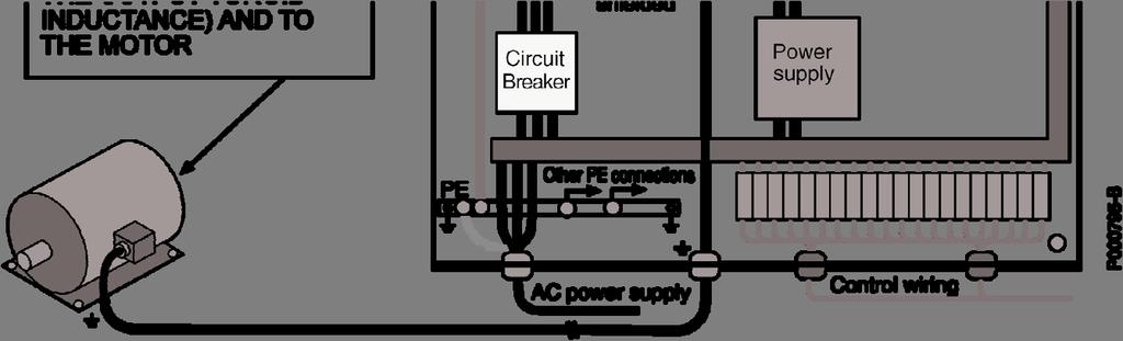

193 INSTALLATION AND PART 3 193/200
194 INSTALLATION AND OUTPUT TOROID FILTERS Ferrite is a simple radiofrequency filter. Ferrite cores are high-permeable ferromagnetic materials used to weaken cable disturbance: - in case of three-phase conductors, all phases must go through the ferrite; - in case of single-phase conductors (or 2-wire line) both phases must go through the ferrite (incoming and outcoming conductor cables that are to be filtered must go through the ferrite). See section Input and Output Filters for the selection of the output toroid filter to weaken radiofrequency interference THE CABINET To prevent input and output of electromagnetic emissions to and from the cabinet, draw particular attention to the cabinet doors, opening and cable paths. A) Use a seam-welded metal frame ensuring electrical continuity. Provide an unpainted, reference grounding support on the frame bottom. This steel sheet or metal grill is to be connected to the metal frame, which is also connected to the ground mains of the equipment. All components must be bolted directly to the grounding support. B) Hinged parts or mobile parts (i.e. doors) must be made of metal and must be capable of restoring electrical conductivity once closed. C) Segregate cables based on the type and intensity of electrical quantities and the type of devices which they are connected to (components that may generate electromagnetic disturbance and components that are particularly sensitive to disturbance): high sensitivity low sensitivity low perturbation high perturbation - analog inputs and outputs: voltage reference and current reference - sensors and measurement circuits (ATs and VTs) - DC supply (10V, 24V) - digital inputs and outputs: optoisolated commands, relay outputs - filtered AC supply - power circuits in general - inverter non-filtered AC supply - contactors - inverter-motor wires Measures to take when wiring the cabinet or the system: - Sensitive signals and perturbator signals must never exist within a cable. - Avoid that cables carrying sensitive signals and perturbator signals run parallel at short distance: whenever possible, paths of cables carrying sensitive signals and perturbator signals should be reduced to a minimum. - The distance between segregated cables should be proportional to the cable length. Whenever possible, cable crossing should be perpendicular. 194/200
195 INSTALLATION AND Wires connecting the motor or load mainly generate disturbance. Disturbance is important in inverter power drive systems or the devices installed on the machine, and could interfere with local communication circuits located near the inverter (radiotelephones, mobile phones). Follow the instructions below to solve these problems: - Provide a motor cable path as short as possible. - Screen the power cables to the motor; ground screening both to the inverter and to the motor. Excellent results are obtained using cables in which the protection connection (yellow-green cable) is external to the screening (this type of cables are available on the market with a cross-section up to 35sqmm per phase). If no screened cable having a suitable cross-section is available, segregate power cables in grounded, metal raceways. - Screen signal cables and ground screening on the inverter side. - Segregate power cable from signal cables. - Leave a clearance of at least 0.5m between signal cables and motor cables. - Series-connect a common mode inductance (toroid) (approx. 100μH) to the inverter-motor connection. Limiting the disturbance in the motor cables will also limit mains disturbance. Screened cables allow both signal sensitive cables and perturbator cables to run in the same raceway. When using screened cables, 360 screening is obtained with collars directly bolted to the ground support. PART 3 195/200
196 INSTALLATION AND INPUT AND OUTPUT FILTERS The inverters of the series may be delivered with incorporated input filters; in that case, models are marked with A1 and A2 in the ID number. If built-in filters are fitted, disturbance amplitude ranges between allowable emission limits as follows: A2 = integrated filter complying with EN (second environment), EN (first environment, category C2, up to Size 0086 included), EN55011 cl. A gr.2 (industrial environment), EN55011 cl. A gr.1 (industrial environment, up to size 0086 included), EN12015 (concerning lifts). A1 = integrated filter complying with the same standards as for A2 and with EN (first environment, category C1), EN55011 cl. B (residential environment), EN (residential environment). To weaken disturbance, an output toroid filter (e.g. 2xK618 filter) can be installed on the Sinus K Lift models provided with integrated A1 filter. Make sure that the three cables between the motor and the inverter go through the core. An output toroid filter is particularly recommended when using a screened cable for the motor wiring. Figure 54: Wiring the toroid filter for the inverters of the SINUS K series. NOTE NOTE Install the output toroid filter near the inverter to comply with the standards in force (leave a minimum clearance for the cable connections); follow the instructions given for the connection of the ground terminals and the terminals of the filter, the motor and the inverter. Install the toroid filter by leading the connection cables between the motor and the inverter inside the toroid. 196/200
197 INSTALLATION AND EUROPEAN UNION DIRECTIVES AND DECLARATIONS OF CONFORMITY PART 3 197/200


198 INSTALLATION AND 198/200


199 INSTALLATION AND PART 3 199/200

200 INSTALLATION AND 200/200
INSTRUCTION MANUAL - Installation Guidelines -
 PB MULTIFUNCTION AC DRIVE INSTRUCTION MANUAL - Installation Guidelines - Updated // R. English This manual is integrant and essential to the product. Carefully read the instructions contained herein as
USER MANUAL -Installation Instructions-
 15P0095B2 FULL DIGITAL INVERTER USER MANUAL -Installation Instructions- Updated 13/04/07 R. 07 English This manual is integrant and essential to the product. Carefully read the instructions contained herein
OPERATION MANUAL -Installation Instructions-
 15P0095B2 FULL DIGITAL INVERTER OPERATION MANUAL -Installation Instructions- Upd. 05/04/06 R 06 English This manual is integrant and essential to the product. Carefully read the instructions contained
S11 Adjustable Speed Drive Engineering Specification
 PART 1 - GENERAL 1.0 Scope This specification shall cover Toshiba S11 AC Variable Frequency Drives, 6 pulse for 3- phase 200-240VAC, 380-500VAC and single phase 200V to 240VAC. 1.1 References A. National
ATV12H018F1 variable speed drive ATV kW hp V - 1ph
 Characteristics variable speed drive ATV12-0.18kW - 0.25hp - 100..120V - 1ph Main Range of product Altivar 12 Product or component type Product destination Product specific application Assembly style Component
ATV12H037F1 variable speed drive ATV kW hp V - 1ph - with heat sink
 Characteristics variable speed drive ATV12-0.37kW - 0.55hp - 100..120V - 1ph - with heat sink Main Range of product Altivar 12 Product or component type Product destination Product specific application
ATV12HU40M3 variable speed drive ATV12-4kW - 5hp V - 3ph - with heat sink
 Characteristics variable speed drive ATV12-4kW - 5hp - 200..240V - 3ph - with heat sink Main Range of product Altivar 12 Product or component type Product destination Product specific application Assembly
ATV12HU22M2. Main. Range of product Altivar 12. Component name Quantity per set Set of 1. Built-in fan. Motor power hp Communication port protocol
 Product datasheet Characteristics ATV12HU22M2 Complementary Main Range of product Altivar 12 Product or component type Product destination Product specific application Assembly style Component name Variable
VF-nC1 Adjustable Speed Drive Engineering Specification
 PART 1 - GENERAL 1.0 Scope This specification shall cover Toshiba VF-nC1 AC Variable Frequency Drives, 6 pulse for 100V single-phase 0.1 to 0.75kW, 200V single-phase 0.2 to 2.2kW and 200V threephase 0.1
Index 2. G Gain settings 4 31 Glossary of terms A 2 Grommets 2 13
 Index A A Group functions 3 9 AC reactors 5 3 Acceleration 1 15, 3 8 characteristic curves 3 26 second function 3 24 two-stage 4 19 Acceleration stop function 3 21 Access levels 3 5, 3 36, 4 25 Access
D.C. BRUSHLESS MOTORS DRIVE. BLD07-IT Service Manual
 D.C. BRUSHLESS MOTORS DRIVE BLD07-IT Service Manual INTECNO s.r.l. Via Caduti di Sabbiuno n. 9/E 40011 Anzola Emilia (BO) - Italy tel. 051.19985350 fax 051.19985360 www.intecno-srl.com INDEX Description
ATV12H037F1 variable speed drive ATV kW hp V - 1ph - with heat sink
 Characteristics variable speed drive ATV12-0.37kW - 0.55hp - 100..120V - 1ph - with heat sink Product availability : Stock - Normally stocked in distribution facility Price* : 191.76 USD Main Range of
Manual Overview...1 2
 GETTING STARTED CHAPTER 1 Contents of this Chapter... Manual Overview.....................................1 2 Overview of this Publication..................................1 2 Who Should Read This Manual...............................1
D SERIES EM16 IP 20 / NEMA 1 & IP 66 / NEMA 4X COMPACT VECTOR CONTROL DRIVE EM 16 COMPACT VECTOR CONTROL DRIVE
 D SERIES EM16 IP 20 / NEMA 1 & IP 66 / NEMA 4X COMPACT VECTOR CONTROL DRIVE EM 16 COMPACT VECTOR CONTROL DRIVE 1 2 SERIES 1 2 pag. 4 pag. 5 Applications Model identification 3 pag. 5 4 pag. 6 Capacity
Ambient Conditions Storage Conditions Installation Minimum Clearances and Air Flow...2 3
 CHAPTER INSTALLATION 2 AND WIRING Contents of this Chapter... Ambient Conditions..............................2 2 Storage Conditions...............................2 2 Installation.....................................2
Variable Frequency Drive / Inverter (0.4 ~ 280kW)
") Variable Frequency Drive / Inverter (0.4 ~ 280kW) & Standard Features Configuration Comparison Comparison Table Enclosure IP00 IP20 NEMA 1 Rating Single phase 0.4 2.2kW 0.4 1.5kW Three phase 0.4 4kW Constant
Variable Frequency Drive / Inverter (0.4 ~ 280kW) & Standard Features Configuration Comparison Comparison Table Enclosure IP00 IP20 NEMA 1 Rating Single phase 0.4 2.2kW 0.4 1.5kW Three phase 0.4 4kW Constant
SECTION 16483D ADJUSTABLE FREQUENCY DRIVE - MICRODRIVE (MVX <10-HP)
") ADJUSTABLE FREQUENCY DRIVE - MICRODRIVE (MVX
ADJUSTABLE FREQUENCY DRIVE - MICRODRIVE (MVX
INDEX. i 1. B Braking Resistor Dimensions: A 24 Braking Resistors: A 20 Braking Units: A 20. DURAPULSE AC Drive User Manual
 INDEX A AC Drive Cover: 1 6 Dimensions: 2 4 External Parts and Labels: 1 6 Heat Sink Fins: 1 6 Input Mode Switch (Sink/Source): 1 6 Introduction to DuraPulse GS3 AC drive: 1 3 Keypad: 1 6 Model Number
System configuration. Ratings 400 V Class three-phase 90 to 800 kw 690 V Class three-phase 90 to 1000 kw SX-D. Frequency inverters.
 ~ ~ SX High performance Vector Control IP54 full range. Compact design & Robustness Built-in Filter according to C3 Class Built-in Fusses (From 200 kw) Safety according EN13849-1 and EN62061 standards
Operating Instructions
 4XH35QB151210 Small General Frequency Converter Operating Instructions 220V 0.75KW 5.5KW 400V 0.75KW 15KW Please read the instruction carefully and understand the contents so that it can be installed and
ADJUSTABLE SPEED DRIVES VF-S11 Sords Electric
 ADJUSTABLE SPEED DRIVES VF-S11 The Next Generation of Micro Inverters is Here. The S11 provides maximum torque with precise speed control. It features an easy-to-use, quiet and compact design. In addition,
E3 Adjustable Speed Drive Engineering Specification
 E3 Adjustable Speed Drive Engineering Specification PART 1 - GENERAL 1.0 Scope This specification shall cover Toshiba E3 AC Variable Frequency Drives, 6 pulse for 230V and 460V. 1.1 References A. National
General Purpose Drives
 AC Variable Speed Drive General Purpose Drives Dedicated to Low Power Applications 0.37kW 11kW / 0.5HP 15HP 200 480V 3 Phase Input AC Variable Speed Drive 0.37kW 11kW / 0.5HP 15HP 110 480V Single & 3 Phase
SX (400 V) System configuration
 System configuration") ~ ~ SX (400 V) High performance Vector Control IP54 full range. Compact design & Robustness Built-in Filter according to C3 Class Built-in Fuses (From 200 kw) Safety according EN13849-1 and EN62061 standards
~ ~ SX (400 V) High performance Vector Control IP54 full range. Compact design & Robustness Built-in Filter according to C3 Class Built-in Fuses (From 200 kw) Safety according EN13849-1 and EN62061 standards
SX (400V) System configuration
 System configuration") ~ ~ SX (400V) High performance Vector Control IP54 full range. Compact design & Robustness Built-in Filter according to C3 Class Built-in Fusses (From 200 kw) Safety according EN13849-1 and EN62061 standards
~ ~ SX (400V) High performance Vector Control IP54 full range. Compact design & Robustness Built-in Filter according to C3 Class Built-in Fusses (From 200 kw) Safety according EN13849-1 and EN62061 standards
SX (690 V) System configuration
 System configuration") SX (690 V) High performance Vector Control IP54 full range Compact design & Robustness Built-in Filter according to C3 Class Built-in Fuses (From 200 kw) Safety according EN13849-1 and EN62061 standards
SX (690 V) High performance Vector Control IP54 full range Compact design & Robustness Built-in Filter according to C3 Class Built-in Fuses (From 200 kw) Safety according EN13849-1 and EN62061 standards
ATS22C21Q soft starter-ats22-control 220V-power 230V(55kW)/ V(110kW)
/ V(110kW)") Characteristics soft starter-ats22-control 220V-power 230V(55kW)/400...440V(110kW) Product availability : Non-Stock - Not normally stocked in distribution facility Price* : 2383.00 USD Main Range of product
Characteristics soft starter-ats22-control 220V-power 230V(55kW)/400...440V(110kW) Product availability : Non-Stock - Not normally stocked in distribution facility Price* : 2383.00 USD Main Range of product
AV-300i Specifications. Saftronics Inc. PC10 Product Specifications PC10. Mini Vector AC Drive
 Saftronics Inc. www.saftronics.com TM AV-300i Specifications PC10 Product Specifications PC10 Mini Vector AC Drive 1 (1) T hree-phas e 230V input Drive Hp 1/8 1/4 1/2 1 2 3 5 7.5 10 Nominal applicable
D SERIES LM16. COMPACT DRIVE V/f and SLV CONTROL. LM16 COMPACT DRIVE V/f and SLV CONTROL
 D SERIES LM16 COMPACT DRIVE V/f and SLV CONTROL LM16 COMPACT DRIVE V/f and SLV CONTROL 1 2 SERIES 1 2 page 4 page 6 Introduction Fields of application 3 page 7 4 page 8 Designation Product offer 5 6 page
LXM32MD18N4 motion servo drive - Lexium 32 - three-phase supply voltage 208/480V kw
 Product data sheet Characteristics LXM32MD18N4 motion servo drive - Lexium 32 - three-phase supply voltage 208/480V - 1.8 kw Main Range of product Lexium 32 Product or component type Device short name
LXM32CD18N4 motion servo drive - Lexium 32 - three-phase supply voltage 208/480V kw
 Product data sheet Characteristics LXM32CD18N4 motion servo drive - Lexium 32 - three-phase supply voltage 208/480V - 1.8 kw Main Range of product Lexium 32 Product or component type Device short name
Frequency Converter Fv vector control converters for universal applications
 Frequency Converter Fv vector control converters for universal applications 2 Our goal: To be world market leader in providing benefits to customers With our broad portfolio of products and services we
Inverter Drive /Vector Drive Motors & Controls
 H2 Inverter/ Encoderless Vector Inverter Drive /Vector Drive & Controls 3/4 thru 50 180-264 VAC 3 Phase - 50/60 Hz 3/4 thru 60 340-528 VAC 3 Phase - 50/60 Hz 3/4 thru 60 515-660 VAC 3 Phase - 60 Hz HVAC
LXM32MU60N4 motion servo drive - Lexium 32 - three-phase supply voltage 208/480V kw
 Product data sheet Characteristics LXM32MU60N4 motion servo drive - Lexium 32 - three-phase supply voltage 208/480V - 0.4 kw Main Range of product Lexium 32 Product or component type Device short name
Installation and Operating Instructions. Power IT Power Factor Controller RVC
 Installation and Operating Instructions Power IT Power Factor Controller RVC Table of contents Page 1. Read this first... 3 About this Instruction Manual... 3 Safety... 3 Electromagnetic compatibility...
ADJUSTABLE SPEED DRIVES. HX7 Series. 18-Pulse
 ADJUSTABLE SPEED DRIVES HX7 Series 18-Pulse Toshiba HX7 In some industrial applications, users need reliable and efficient adjustable speed drives that do not contribute significant harmonic distortion
TECO F510 Inverter. Quick Start Guide. Step 1. Supply & Motor connection
 Quick Start Guide TECO F510 Inverter This guide is to assist you in installing and running the inverter and verify that it is functioning correctly for it s main and basic features. For detailed information
EFC 3600 Frequency converter for higher energy efficiency and improved process control
 EFC 3600 Frequency converter for higher energy eiciency and improved process control 2 Valuable energy used responsibly Rising energy costs and increasing demands on the environmentally sound products
VFSC9 ELECTRONIC SPEED CONTROLLER. Mounting and operating instructions
 ELECTRONIC SPEED CONTROLLER Mounting and operating instructions Table of contents SAFETY AND PRECAUTIONS 3 PRODUCT DESCRIPTION 4 ARTICLE CODES 4 INTENDED AREA OF USE 4 TECHNICAL DATA 4 STANDARDS 5 WIRING
This operation manual is intended for users with basic knowledge of electricity and electric devices.
 This operation manual is intended for users with basic knowledge of electricity and electric devices. Safety Information Safety Information Read and follow all safety instructions in this manual precisely
P-SERIES VFD 1-40HP (200~230VAC), 1-400HP (380~480VAC),3Ø Dual Rated for Constant & Variable Torque Integrated PID Control
, 1-400HP (380~480VAC),3Ø Dual Rated for Constant & Variable Torque Integrated PID Control") P-SERIES VFD 1-40HP (200~230VAC), 1-400HP (380~480VAC),3Ø Dual Rated for Constant & Variable Torque Integrated PID Control NEW FIRMWARE MAKES SETUP A SNAP Application based commissioning allows parameters
P-SERIES VFD 1-40HP (200~230VAC), 1-400HP (380~480VAC),3Ø Dual Rated for Constant & Variable Torque Integrated PID Control NEW FIRMWARE MAKES SETUP A SNAP Application based commissioning allows parameters
TAC ATV38, IP55. Variable Speed Drives for Asynchronous Motors. 3-phase. 380/460 V, Hz
 TAC ATV8, IP55 Variable Speed Drives for Asynchronous Motors. -phase. 80/460 V, 50-60 Hz E-60-24 24 May 2004 ATV 8 IP55 drives are specifically designed for pump and fan applications powered by a three-phase
CHAPTER AC DRIVE PARAMETERS. In This Chapter...
 CHAPTER AC DRIVE 4 PARAMETERS In This Chapter... GS2 Parameter Summary....................4 2 Detailed Parameter Listings.................4 11 Motor Parameters........................4 11 Ramp Parameters.........................4
TECHNICAL SPECIFICATION INVERTER VEGA DRIVE
 TECHNICAL SPECIFICATION INVERTER VEGA DRIVE ELETTRONICA SANTERNO Contents Overview 3 Features & selection guide 4/5 Data sheet 6/7 Wiring & connection terminals 8/9 Keypad & parameters navigation 10/11
INSTRUCTIONS YASKAWA. Upon receipt of the product and prior to initial operation, read these instructions thoroughly, and retain for future reference.
 YASKAWA DUAL ENCODER (PG) FEEDBACK CARD (PG-Z) INSTRUCTIONS Upon receipt of the product and prior to initial operation, read these instructions thoroughly, and retain for future reference. Package Contents:
ADJUSTABLE SPEED DRIVES. AS1 Drive
 ADJUSTABLE SPEED DRIVES AS1 Drive Toshiba s New ASD Product Line The AS1 drive builds on Toshiba s history of supplying powerful, reliable, and versatile drives. We have combined our best drive features
VFD - D700 Series Specifications. The latest low-cost variable speed control solution for centrifugal pumps.
 VFD - D700 Series Specifications The latest low-cost variable speed control solution for centrifugal pumps. Built-in PID Control to maintain pressure, flow, measured value, and much more 125% overload
FREQUENCY INVERTER VFR-013 QUICK START GUIDE
 FREQUENCY INVERTER VFR-013 QUICK START GUIDE Inoréa Automation & Industry 9 rue du Lugan 33130 BEGLES www.inorea.com Table of contents 1. PEOPLE SAFETY... 3 2. MATERIAL SAFETY... 3 3. NAME PLATE... 4 a.
ADJUSTABLE SPEED DRIVES. W7 Series. 18 Pulse
 ADJUSTABLE SPEED DRIVES W7 Series 18 Pulse Meets or Exceeds Your Specifications Standard Specifications Item Voltage Class 460V Maximum HP 60 75 100 125 150 200 250 300 400 500 600 700 800 Drive Rating
FUJI Inverter. Standard Specifications
 FUJI Inverter o Standard Specifications Norminal applied motor The rated output of a general-purpose motor, stated in kw. That is used as a standard motor. Rated capacity The rating of an output capacity,
6.9 Jump frequency - Avoiding frequency resonance
 E581595.9 Jump frequency - Avoiding frequency resonance : Jump frequency : Jumping width Function Resonance due to the natural frequency of the mechanical system can be avoided by jumping the resonant
SAFE TORQUE OFF FUNCTION - Application Manual -
 15W0102B300 SAFE TORQUE OFF FUNCTION - Application Manual - Issued on 04/03/2015 R.00 English This manual is integrant and essential to the product. Carefully read the instructions contained herein as
Industrial motor controller for brushed DC motors 12 VDC
 Industrial motor controller for brushed DC motors 12 VDC Design for output currents up to 5 A Control with the following functions: - reversal of direction of rotation - rotational speed control (external)
HV580 Series Frequency Inverter User Manual
 User Manual HNC Electric Limited Contents Contents...2 Chapter 1 Safety Information and Precautions...4 1.1 Safety Information... 4 1.2 General Precautions...7 Chapter 2 Product Information...10 2.1 Designation
HV580L Series Frequency Inverter User Manual
 User Manual HNC Electric Limited Contents Contents... 2 Chapter 1 Safety Information and Precautions... 4 1.1 Safety Information... 4 1.2 General Precautions... 7 Chapter 2 Product Information... 10 2.1
Invertek Optidrive E3 Frequency Inverter (IP20, 3ph output) Easy Start Guide
 Easy Start Guide") Invertek Optidrive E3 Frequency Inverter (IP20, 3ph output) Easy Start Guide The Invertek Optidrive E3 Frequency Inverter range is available to order from inverterdrive.com This guide is intended to complement
Invertek Optidrive E3 Frequency Inverter (IP20, 3ph output) Easy Start Guide The Invertek Optidrive E3 Frequency Inverter range is available to order from inverterdrive.com This guide is intended to complement
The new Yaskawa Varispeed G7 Inverter
 The new Yaskawa Varispeed G7 Inverter Unique new 3-level PWM flux vector Constant or variable torque applications control method 0.4 kw to 300 kw power range Exceptional low speed/high torque control Quick
Analog Servo Drive 20A20
 Description Power Range NOTE: This product has been replaced by the AxCent family of servo drives. Please visit our website at www.a-m-c.com or contact us for replacement model information and retrofit
CHAPTER MAINTENANCE AND TROUBLESHOOTING. In This Chapter... Maintenance and Inspection Troubleshooting...6 3
 CHAPTER MAINTENANCE AND 6 TROUBLESHOOTING In This Chapter... Maintenance and Inspection.................6 2 Monthly Inspection:..................................6 2 Annual Inspection....................................6
HPVFP High Performance Full Function Vector Frequency Inverter
 Advanced User Manual HPVFP High Performance Full Function Vector Frequency Inverter HP VER 1.00 1. HPVFP Parameter Set Overview...3 1.1. About this section...3 1.2. Parameter Structure Overview...3 1.3.
NX Series Inverters. HVAC Pocket Programming Guide
 NX Series Inverters HVAC Pocket Programming Guide HVAC Pocket Programming Guide HVAC Pocket Programming Guide / Contents This guide provides a single reference document for the user of NXL HVAC (product
LXM32AD18M2 motion servo drive - Lexium 32 - single phase supply voltage 115/230V - 0.5/1kW
 Product data sheet Characteristics LXM32AD18M2 motion servo drive - Lexium 32 - single phase supply voltage 115/230V - 0.5/1kW Main Range of product Lexium 32 Product or component type Device short name
GS1 Parameter Summary Detailed Parameter Listings...4 9
 CHAPTER AC DRIVE 4 PARAMETERS Contents of this Chapter... GS1 Parameter Summary...............................4 2 Detailed Parameter Listings..............................4 9 Motor Parameters.........................................4
Installation and Operational Instructions for ROBA -switch Type 017._00.2
 OBA -switch Type 017._00.2 Guidelines on the Declaration of Conformity A conformity evaluation has been carried out for the product in terms of the EC Low Voltage Directive 2014/35/ EC and the EMC Directive
Power supply CP-D 24/4.2 Primary switch mode power supply
 Data sheet Power supply CP-D 24/4.2 Primary switch mode power supply The CP-D range of modular power supply units in MDRC design (modular DIN rail components) is ideally suited for installation in distribution
Instruction Manual. General application Inverter. IMO idrive2 XKL
 Instruction Manual General application Inverter IMO idrive2 XKL Thank you for purchasing our idrive2 XKL series of inverters. This product is designed to drive a three-phase induction motor. Read through
ATS48D75Y soft starter for asynchronous motor - ATS48-65 A V KW
 Characteristics soft starter for asynchronous motor - ATS48-65 A - 208..690 V - 15..55 KW Main Range of product Altistart 48 Product or component type Product destination Product specific application Device
Type 3RW RW40 7. Control electronics Rated values. Terminal. external DC supply (to DIN 19240) through terminals and IN Relay outputs
 through terminals and IN Relay outputs") Function have all the same advantages as the 3RW30/31 soft starters. At the same they come with additional functions and a two-phase control method (Polarity Balancing) that is unique in the rating range
Function have all the same advantages as the 3RW30/31 soft starters. At the same they come with additional functions and a two-phase control method (Polarity Balancing) that is unique in the rating range
General Specifications FECA-TE /2010. Phone: Fax: Web:
 General Specifications FECA-TE-117 06/2010 1. Standard Specifications 1) Three-phase 230V series Output ratings Input ratings Braking Item Specifications Type (FRN C1S-2U) F12 F25 F50 001 002 003 005 Nominal
15P0073B1. Inverter SINUS M USER MANUAL. Eng lish
 15P0073B1 Inverter SINUS M USER MANUAL Update 04/12/05 R. 00 Eng lish This manual is integrant and essential to the product. Carefully read the instructions contained herein as they provide important hints
SAFETY INSTRUCTIONS WARNING
 Important User Information Thank you for purchasing LS Variable Frequency Drives! SAFETY INSTRUCTIONS Always follow safety instructions to prevent accidents and potential hazards from occurring. In this
G+ Mini Transition Guide. Product Transition Guide P3 Series 2 to G+ Mini
 Transition Guide Product Transition Guide to Rev: Page Intentionally Left Blank Transition Guide September 2008 Page 2 of 24 Table of Contents 1.1 Overview...4 1.2 Drive Replacement Checklist...4 1.3 Ratings
Multi-function, Compact Inverters. 3G3MV Series
 Multi-function, Compact Inverters 3G3MV Series There has been a great demand for inverters with more functions and easier motor control than conventional i OMRON's powerful, compact 3G3MV Series with versat
Industrial motor controller for brushed DC motors 24 VDC
 Industrial motor controller for brushed DC motors 24 VDC Design for output currents up to 5 A Control with the following functions: - reversal of direction of rotation - open-loop speed control (external)
Power supply CP-E 24/2.5
 2CDC 271 015 F0t06 a OUTPUT L+, L : terminals output b DC OK: terminal signalling output c INPUT L, N, PE: terminals input d OUTPUT OK: green LED output voltage OK e OUTPUT Adjust: potentiometer adjustment
AxCent Servo Drive A50A100
 Description Power Range The A50A100 PWM servo drive is designed to drive brushed type DC motors at a high switching frequency. A single red/green LED indicates operating status. The drive is fully protected
LXM32AD72N4 motion servo drive - Lexium 32 - three-phase supply voltage 208/480V kw
 Product data sheet Characteristics LXM32AD72N4 motion servo drive - Lexium 32 - three-phase supply voltage 208/480V - 0.4 kw Main Range of product Lexium 32 Product or component type Device short name
vacon nxs robust drive for heavy use
 vacon nxs robust drive for heavy use the reliable choice The Vacon is a compact AC drive in the power range of 0.7 560 kw and supply voltages of 208 690 V for heavy use in machines, buildings and all branches
Altivar 28 drive Altivar 28 enclosed drive
 Telemecanique drive enclosed drive March 00 Characteristics : pages 0 to pages 4 to 2 Dimensions, schemes : pages 24 to 29 Presentation, functions Presentation A frequency inverter for -phase asynchronous
ADJUSTABLE SPEED DRIVES. HX7 Series. 18 Pulse. Phone: Fax: Web: -
 ADJUSTABLE SPEED DRIVES HX7 Series 18 Pulse Toshiba HX7 In some industrial applications, users need reliable and efficient adjustable speed drives that do not contribute significant harmonic distortion
Analog Servo Drive 30A8
 Description Power Range NOTE: This product has been replaced by the AxCent family of servo drives. Please visit our website at www.a-m-c.com or contact us for replacement model information and retrofit
IF30. User's manual. Description. Table of contents IF30
 User's manual IF30 Description IF30 is an encoder interface unit designed to convert the output signals delivered by so-called sine-cosine-encoders and similar measuring systems (devices which deliver
Power supply CP-E 24/20.0
 2CDC 271 027 F0008 a OUTPUT L+, L+, L, L-: terminals output b INPUT L, N, PE: terminals input c 13-14: terminals - signalling contact d OUTPUT OK: green LED output voltage OK e OUTPUT LOW: red LED output
MAKING MODERN LIVING POSSIBLE. Operating Instructions. VLT Refrigeration Drive FC kw
 MAKING MODERN LIVING POSSIBLE Operating Instructions VLT Refrigeration Drive FC 103 1.1-90 kw Safety Safety WARNING HIGH VOLTAGE! Frequency converters contain high voltage when connected to AC mains input
Goodrive 300 Inver ter
 Goodrive 300 Inver ter Preface Preface Thanks for choosing our products. Goodrive300 series inverters are high performance open loop vector inverters for controlling asynchronous AC induction motors and
Dynamo Brushless DC Motor and GreenDriveTM Manual
 Dynamo Brushless DC Motor and GreenDriveTM Manual This manual was developed as a guide for use by FIRST Robotics Teams using Controller Part Number 840205-000 in conjunction with the Nidec Dynamo BLDC
8V General information. 2 Order data 8V
 8V05.00-8V05.00- General information Modular mechanical design using plug-in modules Integrated line filter Integrated braking resistor All connections are made using plug-in connectors Integrated electronic
CONTENTS XV300K GB r doc XV300K 2/13
 XV300K CONTENTS 1 PRELIMINARY CHECK GUARANTEE RECYCLING... 3 2 XV300K SPECIFICATIONS OF USE... 3 3 CODES - MODELS... 4 4 TECHNICAL SPECIFICATIONS... 4 5 STANDARD REFERENCES... 5 6 MECHANICAL INSTALLATION...
Softstarters. Specification guide. Type PST. Low Voltage Products & Systems
 Softstarters Type PST Low Voltage Products & Systems 2 Low Voltage Products & Systems 1SXU132171M0201 [AC 1006.8] - 5/03 ABB Inc. 888-385-1221 www.abb.com/lowvoltage Softstarters Type PST Specification
FREQUENCY-CONVERTER MFR 600A / 1500A Version 2
 Technical documentation for: FREQUENCY-CONVERTER MFR 600A / 1500A Version 2 Contents: 1. General description 2. Technical data 3. Function of the ramp generator 4. Electrical connection, examples for the
Analog Servo Drive 100A40
 Description Power Range The 100A40 PWM servo drive is designed to drive brush type DC motors at a high switching frequency. A single red/green LED indicates operating status. The drive is fully protected
RSMFX-2R MULTIFUNCTIONAL
 Mounting and operating instructions Table of contents SAFETY AND PRECAUTIONS 3 PRODUCT DESCRIPTION 4 ARTICLE CODES 4 INTENDED AREA OF USE 4 TECHNICAL DATA 4 STANDARDS 4 OPERATIONAL DIAGRAMS 5 WIRING AND
15P0059B3 DCREG2 DCREG4 USER MANUAL
 15P0059B3 DCREG2 15/07/08 R.06 SOFTWARE VERSION D5.00 English This manual is an integral and essential part of the product. Carefully read the instructions contained herein as they provide important hints
BC145 SIGNAL ISOLATOR BOARD
 BC145 SIGNAL ISOLATOR BOARD 4/17 Installation & Operating Manual MN1373 Any trademarks used in this manual are the property of their respective owners. Important: Be sure to check www.baldor.com to download
MU110-8R(K) Digital output module 8 channel. User guide
 Digital output module 8 channel. User guide") MU110-8R(K) Digital output module 8 channel User guide MU110-8R(K)_2019.01_0296_EN All rights reserved Subject to technical changes and misprints akytec GmbH Vahrenwalder Str. 269 A 30179 Hannover Germany
MU110-8R(K) Digital output module 8 channel User guide MU110-8R(K)_2019.01_0296_EN All rights reserved Subject to technical changes and misprints akytec GmbH Vahrenwalder Str. 269 A 30179 Hannover Germany
ATV212HU22M3X variable speed drive ATV kW - 3hp - 240V - 3ph - wo EMC - IP21
 Product data sheet Characteristics ATV212HU22M3X variable speed drive ATV212-2.2kW - 3hp - 240V - 3ph - wo EMC - IP21 Product availability : Stock - Normally stocked in distribution facility Price* : 618.00
MU110-16R(K) Digital output module 16 channel. User guide
 Digital output module 16 channel. User guide") MU110-16R(K) Digital output module 16 channel User guide MU110-16R(K)_2016.12_0220_EN All rights reserved Subject to technical changes and misprints akytec GmbH Vahrenwalder Str. 269 A 30179 Hannover Germany
MU110-16R(K) Digital output module 16 channel User guide MU110-16R(K)_2016.12_0220_EN All rights reserved Subject to technical changes and misprints akytec GmbH Vahrenwalder Str. 269 A 30179 Hannover Germany
ADJUSTABLE SPEED DRIVES FS1
 ADJUSTABLE SPEED DRIVES FS1 Now Available With LonWorks BACnet & MetasysN2 FS1 Model FLA & Dimensions (in.)/ Weight (lbs.) VOLTAGE HP MODEL NUMBER FLA FRAME Dimensions (in.) SHIPPING H W D WEIGHT (lbs.)
Analog Servo Drive 25A20DD
 Description Power Range NOTE: This product has been replaced by the AxCent family of servo drives. Please visit our website at www.a-m-c.com or contact us for replacement model information and retrofit
R&D TECHNICAL SPECIFI
 INTRODUCTION Present document defines technical specs of a three phase UPS covering the power range from 20 to 30 kva ON-LINE DOUBLE CONVERSION Uninterruptible Power Supply Systems with forced ventilation