Handbook Ref No. MH079/Issue E File Ref: UV2033vE.doc
|
|
|
- Abraham Golden
- 5 years ago
- Views:
Transcription


1 Handbook Ref No. MH079/Issue E File Ref: UV2033vE.doc
2
3 1. Introduction 2. Specification 3. Power On / Detector Select Sequence 4. Operation 5. Irradiance Measurements 6. Cosine Angular Response 7. Calibration Description 8. Care and Maintenance 9. Block Diagram 10. Programming via the RS232 interface 11. Environmental care, recycling and disposal Handbook Update Log Issue Date Pages changed A 27/7/99 New Issue B 23/11/00 Version 5 programming C 18/06/02 Calibration update D 18/12/07 Performance update E 19/12/11 Handbook reformat
4
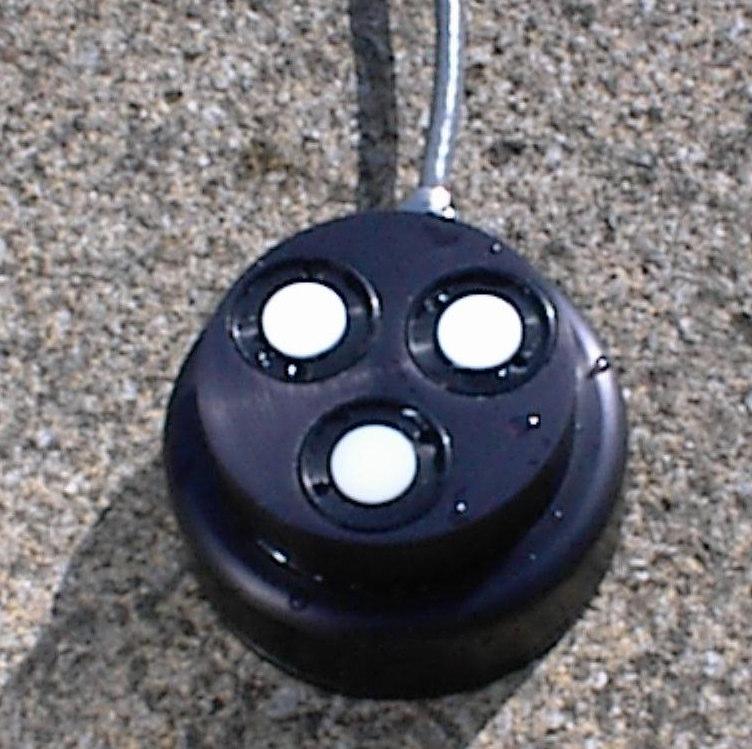
5 Irradian Limited The Irradian portable radiometer model UV203-3 is specially designed for the measurement of underwater irradiance in the UVA band, the UVB2 band and the radiometric band between 400 and 700nm. The equipment comprises of a display unit and a submersible detector head with three photodiode detectors, linked with a robust 10 metre cable. The micro-processor controlled display unit features a 4½ digit direct reading liquid crystal display, auto or manual gain control of the detector amplifiers and detector selection. Operations include back ground zero measurement and display hold. The radiometer can also be used to measure the average irradiance on a selected detector and record the minimum and maximum values during the averaging period. In addition the integrated irradiance in mj/m² or J/m² is calculated. The detector head comprises of three, high stability photodiode detectors with glass absorption filters for the selected spectral band and a cosine corrected input diffuser. Each of the detectors has its own high gain, low noise amplifier and digitiser. This design ensures only resilient digital signals are transmitted along the interconnecting cable. The model UV203-3 provides the following: 1 UV203-3 display unit with two PP9 type batteries 1 DET203-3UV-VIS triple detector with 10 metre cable 1 RS232 interface cable 1 Blanking plate 1 Handbook 1 Calibration certificate 1 CC-8 Foam lined carrying case. 1
6 DISPLAY UNIT Controller: Memory Key Operation Power Switch Serial Interface UV C51 8bit micro-processor with a MHz clock. On board non volatile RAM for calibration factors and set-up parameters. 7 switch key board with 11 LED indicators. (display backlight not fitted) Microprocessor reset at switch on. Background zero levels stored prior to shut off. Three wire RS232 serial interface baud, no parity, 1 stop bit. Integration Time 0.33s Conversion Scale Accuracy: Display: Power Supply: 17 bit Measurement accuracy ±1digit with a linearity error of <1%. 4½ digit LCD. Character height 10mm. Two, 9 volt PP3 Alkaline. Power Consumption: Shut down mode <5µA Operating 10-20mA Operating with RS ma Battery Life 150 hours*. * = without RS232 interface connection. 2
7 (continued): Ranges: Each of the filter rings have up to six ranges according to the table below: Full Scale \ Filter Ring UVA UVB2 RFF-Vis mw.m mw.m mw.m mw.m W.m W.m W.m W.m x10 W.m -2 Calibration Type: Standard Standard Mercury Note: Other filter rings and ranges are available on request. Standard Calibration: Mercury Calibration: The radiometer with detector and filter rings is calibrated at the peak response of each filter ring using a monochromatic source. The calibration plane is at the front of the filter face. The radiometer with detector and filter rings is calibrated at a wavelength corresponding to a mercury emission line. The calibration plane is 34 mm back from the front of the filter face, corresponding to the position of the photodiode. Spectroradiometric Cal. The radiometer with detector and filter rings is calibrated to match the measurement of a spectroradiometer on a particular source. Accuracy Absolute calibration accuracy ±7.5% traceable to NPL standards. 3
8 (continued): RS232 x4 DETECTOR +9V EXT. EXT. SUPPLY ON/OFF 203 Optical Radiometer Cover fixing screws Detector select button 4½ digit LCD display MODE select button Background ZERO button FUNCTION RESET button Mode RESET button Display HOLD Function RUN button Auto/manual RANGE button Power switch button. 4
9 (continued): Front Panel Controls: RANGE UNITS ZERO HOLD/RUN MODE FUNCTION/RESET RESET Detector Connector: RS232 Connector: Ext. power supply: Select auto ranging or manual range control. Select between UVA, UVB and RFF detectors. Initiates a zero or background measurement routine on all gain ranges. Display is held at present reading until HOLD button is pressed again. Select to run or hold a special mode. Select between, AVERAGE, MIN, MAX and INTEGRATE modes. Press RESET to return to normal measurement mode. Press to reset function values to zero Press to return to normal measurement mode from Manual range control or special modes. Note the display hold is not reset. Power on / off button Display backlight on off button (not fitted). 8 pin circular screw lock type connector. 5 pin circular screw lock type connector. 3 pin circular screw lock type connector. Temperature Range: 0 to 40 C. 80% RH. Dimensions: Protection: Weight: 180 x 130 x 60mm. High impact polystyrene. IP67 (short term soaking) 500g 5
10 (continued): SEALED TRIPLE DETECTOR, Model DET203-3UV-Vis The DET203-3UV-Vis detector comprises of an aluminium housing, three photodiode detectors with filter glasses amplifier and digitiser. Detector Housing: Cable: Black anodised aluminium alloy housing. Sealed waterproof to 10 metres 10 metre cable to 8 pin type connector UVA Detector RFF Detector UVB Detector 6
11 (continued): UVA DETECTOR Detector: 33mm² Silicon photodiode. Spectral response: Ref figure 1 λ 369 ±2nm, FWHM 37 ±2nm. Visible & NIR Blocking: >10 5 from 420 to 1000nm Angular Response: Temperature Coefficient: -0.1 to -0.2 %/ C Amplifier Gain Current to Frequency Linearity Error: Temperature Range: Accurately cosine corrected to Lambert's Cosine Law. Maximum error is less than ±3% from true response to 70 from normal incidence, reference section 4. 5x10 9 V/A to 5x10 3 V/A 0-0.5Mhz <1% across ranges Operation: 0 to +40 C Storage: -20 to +60 C Spectral Response of UVA Detector R e s p o n s e % Wavelength (nm) Figure 1 7
12 (continued): UVB2 DETECTOR Detector: 21mm² GaAsP photodiode. Spectral response: Ref figure 2 λ 311 ±1nm, FWHM 19 ±2nm. Visible & NIR Blocking: >10 5 from 400 to 1000nm Angular Response: Temperature Coefficient: to -0.2 %/ C Amplifier Gain Current to Frequency Linearity Error: Temperature Range: Accurately cosine corrected to Lambert's Cosine Law. Maximum error is less than ±3% from true response to 70 from normal incidence, reference section 4. 5x10 9 V/A to 5x10 3 V/A 0-0.5Mhz <1% across ranges Operation: 0 to +40 C Storage: -20 to +60 C Spectral Response of UVB2 Detector R e s p o n s e % Wavelength (nm) Figure 2 8
13 (continued): RFF DETECTOR Detector: Spectral response: Ref figure 3 Angular Response: 33mm² Silicon photodiode. Temperature Coefficient: 0 to -0.1 %/ C Amplifier Gain Current to Frequency Linearity Error: Temperature Range: Accurately cosine corrected to Lambert's Cosine Law. Maximum error is less than ±3% from true response to 70 from normal incidence, reference section 4. 5x10 9 V/A to 5x10 3 V/A 0-0.5Mhz <1% across ranges Operation: 0 to +40 C Storage: -20 to +60 C Spectral Response of RFF Detector R e s p o n s e % Wavelength(nm) Figure 3 9
14 POWER ON READ STORED CALIBRATION & ZERO LEVELS SELECT UVA DETECTOR AUTO RANGE UVA AMPLIFIER GAIN MEASURE UVA SIGNAL SUBTRACT ZERO LEVEL DISPLAY IRRADIANCE PRESS DETECTOR SELECT BUTTON PRESS DETECTOR SELECT BUTTON FOR RFF DETECTOR ZERO RANGE MODE FUNCTION RESET RUN HOLD RESET AUTO RANGE UVA AMPLIFIER GAIN MEASURE UVA SIGNAL SUBTRACT ZERO LEVEL DISPLAY IRRADIANCE ZERO RANGE MODE FUNCTION RESET RUN HOLD RESET 10
15 SETTING UP 1) With the unit OFF, screw the detector 8 way connector into the detector socket on the top of the display unit. 2) Note: Carefully clean the white cosine diffuser inputs on the top of the detector if they are marked or dirty. 3) Press and release the power switch on the UV203-3 display key pad. The micro controller will initiate with the display momentarily showing:- The radiometer will now search for the optimum range on the detector amplifier. A typical display is shown below. An LED will illuminate indicating the UVA detector selection and calibration with either the mw.m -2 or W.m -2 units LED on. 4) Press and release the UNITS switch to select the detector and calibration required. 5) It is recommended that the radiometer amplifiers are nulled periodically. Place the cover over the detector. Press and release the ZERO switch, the display will momentarily show:- Note it is necessary to perform the nulling procedure on each detector amplifier. The values for the three detector amplifiers are stored separately in the non volatile memory. 11
16 (continued): 6) The micro controller will now measure the amplifier offset on each of the gain ranges and store these values in the non volatile memory. All subsequent measurements will first have one of these offsets subtracted before displaying the measurement. At the end of the nulling sequence the display will show:- Note if the radiometer units are set to UVB the display will show and if set to RFF the display will show If the display does not show that the amplifier offset has been nulled, repeat the operation once again to give the display shown above. 7) Remove the detector light cover. The equipment is now ready for use. AVERAGE When the light is unstable, press and release the MODE switch. The radiometer will now switch to manual ranging, Manual LED on, if not yet previously in manual ranging. The Average LED will now switch on, but the Units LED will remain unchanged. To start an average sequence press and release the HOLD/RUN switch. Immediately the display will show a fluctuating signal, reflecting the light source fluctuations. After a short time the amplitude of the fluctuations will decrease and the display will begin to show a reading which represents the average light level during the period of the measurement. The averaging process can be halted by pressing the HOLD/RUN button. At any time the averaging sequence can be reset by pressing and releasing the FUNCTION RESET switch. If the light level fluctuations are large and any one reading causes the detector amplifier to overload at this range the averaging process will be terminated and the display will show:- To avoid an overload condition, RESET the radiometer and manually change the RANGE to a lower gain. e.g. from a range to
17 (continued): MIN & MAX LEVELS During an average measurement sequence the maximum and minimum values attained in the period are recorded. Press HOLD to halt the averaging sequence. Press the MODE button to select between Average, Min and Max. Note the Integrate display may overload and show - 0 L -. It is also possible to view a MIN or MAX recording sequence by selecting MIN or MAX prior to selecting RUN. Press FUNCTION RESET to set the maximum and average values to zero and the minimum to - 0 L -. Note the FUNCTION RESET will operate during a measurement sequence or in the HOLD mode. INTEGRATE For measurements of the integrated dosage or exposure press the MODE switch to select Integrate. Press the RUN switch to start the measurement. The display will now autorange as the dosage increases. Note the detector amplifier will not autorange and as with Average measurements if the amplifier overloads the display will show - 0 L - and the measurement will halt. Units for integrated measurements are shown below the main units on the radiometer, (in parenthesis) mj.m -2 and J.m -2. At the end of the integration period HOLD the display. Use the MODE switch to also display the Min, Max and Average values. Press FUNCTION RESET to set the integrate, maximum and average values to zero and the minimum to - 0 L -. Note the FUNCTION RESET will operate during a measurement sequence or in the HOLD mode. 13
18 CAUTION: ULTRA VIOLET RADIATION IS HAZARDOUS TO BOTH THE EYES AND SKIN. TAKE CARE TO AVOID PERSONAL EXPOSURE DURING MEASUREMENTS. Irradiance is the measurement of radiometric light per unit area, watts per metre, W/m -2. The part of the spectrum to be measured is defined by the filter fitted onto the detector. Ideally this should be a filter with a square spectral response. In practice it rarely is and the filter is defined with a peak response wavelength and a full width half maximum, FWHM bandwidth. In all applications it is vital to know the part of the spectrum being measured by the detector and filter, and if possible to know the spectrum of the light source. In addition the radiometer should be calibrated to best suit the measurement conditions. It may even be necessary to have more than one calibration factor for the same detector / filter combination. For most applications the measurement plane is horizontal and a cosine corrected diffuser is fitted to the front of the detector assembly. If the working surface is not horizontal then placing the detector on or parallel to the worktop is a more representative measurement of irradiance. Note that all the light sources in the hemisphere above the detector will contribute to the measurement. The sources may be obvious, lamps or windows or even walls or other reflecting surfaces. Take care not to shadow the detector during all measurements. Each detector has its own cosine corrected diffuser. Measurement errors will increase as the angle of irradiance increases from the normal to the filter ring front surface. A useful technique for measuring the sensitivity of the detector filter to non ultra violet light is to place a high pass filter glass over the front of the filter ring and record the reading. If the high pass filter blocks all the light across the spectral response region of the UV filter then a zero reading would imply the detector/filter is only sensitive to the UV light. Readings other than zero would imply there is some sensitivity to visible or near infra-red light. 14
19 ! " Irradiance is a measurement of the amount of light incident on a unit area (watts/m²). Any detector will measure this reliably when measuring a beam of light perpendicular to the detectors surface, however, when measuring scattered light or light from an extended source the sensor must have an accurate response over its 180 field of view. More importantly, this response should be proportional to the cosine of the angle of light incident on the detector. This comes from the fact that the projected area of any surface at an angle of i is proportional to Cos(i). To ensure that the integration of light from all angles is correct, the cosine diffuser matches the angular response so that response of the detector decreases with Cos(i) as the angle between the source and detector increases from 0 to 90. UV* Cos-113 True Cosine Response Figure 6 Irradian's cosine diffusers are corrected to match the cosine response to within ±3.5% up to angles of 70. This ensures that the meter correctly reads illuminance or visible light flux density whether it is measuring light from an extended or a point source. 15
20 # Irradian holds a number of tungsten halogen and deuterium lamps and a silicon photodiode which are routinely calibrated by the National Physics Laboratory in the UK. During manufacture each filter ring and detector has its spectral response measured. Changes are made to the filter glasses if the peak wavelength or filter bandwidth exceed the specification limits. A graph of the final filter/detector response is provided. The data on a disk is also available on request for importing to a spreadsheet. The radiometer with detector and filter rings is calibrated using monochromatic light at the peak wavelength of each filter or at a specified wavelength (ref calibration certificate). Other calibration techniques can be applied to suit the users application. For example matching the radiometer output to the output from a high accuracy spectroradiometer (SR9910) for a particular light source like PUVA tubes. As with all measuring equipment a routine calibration is recommended, typically annually, but with frequent use by a number of different users a shorter recalibration period may be necessary. Contact Irradian for any calibration requirements for this product and for further information. 16
21 $ 1) The UV203-3 display unit can be cleaned using a moist cloth with detergent. Do not use solvent or alcohol to clean surfaces. 2) The diffuser on each filter ring should be kept clean at all times. 3) The radiometer is a precision instrument, protect from shocks. 4) Avoid supporting the detector by the multi core cable. 17
22 % " Diffuser Filter Detector RS232 Driver Gain Control Amp v to f Multiplexer Counter Liquid Crystal Display µcontroller Display Driver UVA Detector/Amplifier Non Volitile RAM Diffuser Filter Detector Gain Control Keypad & LEDs Amp v to f Micro-Controlled Display Unit UVB Detector/Amplifier Diffuser Filter Detector Gain Control Amp v to f RFF Detector/Amplifier 18
23 "" " Serial Port Settings: 4800 baud, no handshaking Single letter commands S U F I H Z R B s t Toggle through possible gain ranges (manual mode) Reset to autorange with R command. Toggle through possible units, UVA, UVB & RFF as applicable. Toggle through possible functions. Function reset. Toggles hold/go. Zeros light meter. Resets light meter. Toggles backlight. Sends data continuously via the RS232. Sends one set of data via the RS
24 "" (continued): 10.1 Windows 3.1 & Windows 95 Setting up remote control via Microsoft TERMINAL.EXE 1) Connect the cable between the RS232 socket on the light meter and the COM port on the PC. 2) Switch on the light meter. 3) Run Terminal programme. 4) Go to the Settings / Communications screen and set the baud to 4800 and the COM port to suit. 5) Go to the Settings / Text Transfers and select Line at a time with 1/10th second delay. 6) Check the RS232 link by a switch to the manual range, LED on using the command 'S', (capital S). 7) Reset to the auto range, LED off using the command 'R', (capital R). 8) Type 't' for one packet of data and 's' for continuous data. Type 's' to stop the data flow. 9) To save the terminal setup go to File / Save As and save the settings. When restarting the programme the settings can be reloaded with File / Load filename. Now actions 4 and 5 can be omitted. Logging data continuously to a file using Microsoft TERMINAL.EXE 1) Run the Terminal programme with the correct settings. 2) Set up the radiometer and send the command 's' via Terminal to transmit data continuously from the radiometer. 3) Go to Transfers / Receive Text File. Enter filename for the stored data (e.g. log1.txt). 4) On entering the file name, Terminal will now store all the readings transmitted from the radiometer in a file log1.txt. The file is saved to the computer by pressing STOP on the terminal screen. 20
25 "" (continued): 10.2 Windows 95 & Windows 98 Setting up remote control via Microsoft HYPERTERMINAL.EXE 1) Connect the cable between the RS232 socket on the light meter and the COM port on the PC. 2) Switch on the light meter. 3) Run the HyperTerminal programme. 4) Enter a name for the session (e.g. UV203 etc.). 5) Select the type of connection required, either option 'direct to com 1' or 'direct to com 2' depending on which com port is to be used. 6) Enter the details for the serial connection: 4800 bits per second, 8 data bits, no parity, 1 stop bit and no flow control. 7) Click the properties icon or select via the File / Properties option to display the properties window. 8) Select the Settings tab and select Auto detect for the Emulation setting. 9) Click the ASCII Setup button. Enter 100 into the box marked Line delay. No other options are necessary. Click on OK to return to the main window. 10) Check the RS232 link by downloading a reading using the command 't', (lowercase t). This also allows auto detect to correctly identify the meter settings, showing N-1 next to the Auto detect message in the status bar. A reading should appear in the main window if the connection has been made successfully. 11) To save the terminal setup go to File / Save As and save settings. When restarting the programme the settings can be loaded directly by double-clicking on the *.ht icon that has been created. Now actions 4 to 9 can be omitted. 21
26 "" (continued): Logging data to a file using Microsoft HYPERTERMINAL.EXE 1) Run the HyperTerminal programme with the correct settings. 2) Set up the radiometer and send the command 's' via HyperTerminal to transmit data continuously from the radiometer. 3) Go to Transfer / Capture Text. Enter the filename for the stored data and the location to save to. (e.g. C:\HyperTerminal\Capture.txt). 4) Press the start button to store all the readings transmitted from the radiometer in a file Capture.txt. The status bar will now show a highlighted 'Capture' message. The file is saved to the computer by selecting Transfer / Capture Text / Stop. 5) Send the command 's' again via HyperTerminal to stop the continuous transitional of data from the radiometer. 22

27 &'" The purpose of the European Commission WEEE directive (Waste Electrical and Electronic Equipment; 2002/96/EC) is to ensure that electrical and electronic products are recycled using the best treatments, recovery and recycling techniques that are currently available. This is so that high health standards and a lasting environmental protection can be achieved and maintained. This product has been designed and manufactured using high quality materials and components, many of which can be recycled and reused. Please remember to observe the local regulations that govern both the disposal of the packaging materials accompanying this product and any used batteries. DO NOT DISPOSE OF THIS PRODUCT IN YOUR GENERAL WASTE BIN. Please inform yourself about your local WEEE collection system which is available for electrical and electronic products that are marked with the symbol shown here. When disposing of this meter, please use one of the following options: 1) Use your local designated WEEE collection facilities to dispose of the complete product (including cables, detectors, filters & accessories). 2) Return the complete product back to Irradian, marking it clearly as intended for WEEE disposal. 23
28
29
30
31
32 () 9 Elphinstone Road Telephone: +44 (0) Tranent Facsimile: +44 (0) East Lothian info@irradian.co.uk Scotland EH33 2LG Web:
Handbook Ref No. IH001/Issue D File Ref: PR203-v5D.doc
 Handbook Ref No. IH001/Issue D File Ref: PR203-v5D.doc 1. Introduction 2. Specification 3. Operation 4. Spectral Irradiance Measurements 5. Cosine Angular Response 6. Calibration Description 7. Care and
Handbook Ref No. MH063/Issue L File Ref: L203-v5L.doc
 Handbook Ref No. MH063/Issue L File Ref: L203-v5L.doc 1. Introduction 2. Specification 3. Operation 4. Illuminance Measurements 5. Luminance Measurements 6. Battery Replacement 7. Photopic Response 8.
Light Sensors for Environmental Chambers
 Skye Instruments Ltd., 21 Ddole Enterprise Park, Llandrindod Wells, Powys LD1 6DF UK Tel: +44 (0) 1597 824811 skyemail@skyeinstruments.com www.skyeinstruments.com Iss. 1.2 2 1 Skye Instruments Ltd. Skye
UV-A, UV-B & UV-I Sensors
 UV-A, UV-B & UV-I Sensors SKU 400 Series Skye Instruments Ltd. 21 Ddole Enterprise Park Llandrindod Wells Powys LD1 6DF UK Tel: +44 (0) 1597 824811 skyemail@skyeinstruments.com www.skyeinstruments.com
Red/Far-Red Sensor SKR 110. Skye Instruments Ltd., 21 Ddole Enterprise Park, Llandrindod Wells, Powys LD1 6DF UK Tel: +44 (0)
") SKR 110 Skye Instruments Ltd., 21 Ddole Enterprise Park, Llandrindod Wells, Powys LD1 6DF UK Tel: +44 (0) 1597 824811 skyemail@skyeinstruments.com www.skyeinstruments.com Iss. 1.1 Skye Instruments Ltd.
SKR 110 Skye Instruments Ltd., 21 Ddole Enterprise Park, Llandrindod Wells, Powys LD1 6DF UK Tel: +44 (0) 1597 824811 skyemail@skyeinstruments.com www.skyeinstruments.com Iss. 1.1 Skye Instruments Ltd.
2 Channel Light Sensor
 SKR 1840 Skye Instruments Ltd., 21 Ddole Enterprise Park, Llandrindod Wells, Powys LD1 6DF UK Tel: +44 (0) 1597 824811 skyemail@skyeinstruments.com www.skyeinstruments.com Iss. 1.1 Skye Instruments Ltd.
4 Channel Light Sensor
 SKR 1850 Skye Instruments Ltd., 21 Ddole Enterprise Park, Llandrindod Wells, Powys LD1 6DF UK Tel: +44 (0) 1597 824811 skyemail@skyeinstruments.com www.skyeinstruments.com Iss. 1.2 Skye Instruments Ltd.
4 - Channel SWIR Light Sensor
 SKR 1870 Skye Instruments Ltd., 21 Ddole Enterprise Park, Llandrindod Wells, Powys LD1 6DF UK Tel: +44 (0) 1597 824811 skyemail@skyeinstruments.com www.skyeinstruments.com Iss. 1.2 Skye Instruments Ltd.
HD HD HD AND HD PHOTO-RADIOMETERS LG-2
 HD 22. HD 22.2 INSTRUMENT TECHNICAL CHARACTERISTICS Instrument Dimensions (Length x Width x Height) 85x9x4mm Weight 47g (complete with batteries) Materials Display ABS, rubber 2x4½ digits plus symbols
Gentec-EO USA. T-RAD-USB Users Manual. T-Rad-USB Operating Instructions /15/2010 Page 1 of 24
 Gentec-EO USA T-RAD-USB Users Manual Gentec-EO USA 5825 Jean Road Center Lake Oswego, Oregon, 97035 503-697-1870 voice 503-697-0633 fax 121-201795 11/15/2010 Page 1 of 24 System Overview Welcome to the
LP PHOT LP RAD 03 LP PAR 03 LP UVA 03 LP UVB 03 LP PHOT 03S. Light
 LP PHOT 0 LP RAD 0 LP PAR 0 LP UVA 0 LP UVB 0 LP PHOT 0S : λ) f (agreement with the standard curve V(λ f (Cosine response)
BTS256-E WiFi - mobile light meter for photopic and scotopic illuminance, EVE factor, luminous color, color rendering index and luminous spectrum.
 Page 1 BTS256-E WiFi - mobile light meter for photopic and scotopic illuminance, EVE factor, luminous color, color rendering index and luminous spectrum. The BTS256-E WiFi is a high-quality light meter
BTS256-EF. Product tags: VIS, Spectral Measurement, Waterproof, WiFi. Gigahertz-Optik GmbH 1/7
 BTS256-EF http://www.gigahertz-optik.de/en-us/product/bts256-ef Product tags: VIS, Spectral Measurement, Waterproof, WiFi Gigahertz-Optik GmbH 1/7 Description Traditional lux meters are increasingly being
UV / VIS Spectrophotometer EMCLAB Instruments GmbH
 A Professional Manufacturer UV / VIS Spectrophotometer EMCLAB Instruments GmbH EMCLAB Instruments GmbH Bismarckstrasse 120 47057 Duisburg Germany Phone: +49 203 3064042 Fax: +49 203 3064044 E-mail: info@emc-lab.de
Product tags: VIS, Spectral Data, Color Temperature, CRI, Waterproof, WiFi, Luminous Color, LED, Photometry, General lighting
 BTS256-EF https://www.gigahertz-optik.de/en-us/product/bts256-ef Product tags: VIS, Spectral Data, Color Temperature, CRI, Waterproof, WiFi, Luminous Color, LED, Photometry, General lighting Gigahertz-Optik
SPECTRAL IRRADIANCE DATA
 The radiometric data on the following pages was measured in our Standards Laboratory. The wavelength calibrations are based on our spectral calibration lamps. Irradiance data from 250 to 2500 nm is based
BTS2048-UV. Product tags: UV, Spectral Data, LED Binning, Industrial Applications, LED. https://www.gigahertz-optik.de/en-us/product/bts2048-uv
 BTS2048-UV https://www.gigahertz-optik.de/en-us/product/bts2048-uv Product tags: UV, Spectral Data, LED Binning, Industrial Applications, LED Gigahertz-Optik GmbH 1/8 Description UV CCD spectroradiometer
LI-192 Underwater Quantum Sensor
 LI-192 Underwater Quantum Sensor The LI-192 Underwater Quantum Sensor measures PAR from all angles in one hemisphere. The LI-192 works in air or underwater at depths up to 560 meters. The measurements
Features. Description. General Specifications. VS Series Inclinometer : Dual Axis, RS232 and Analogue Output
 Features Dual axis measurement from ±5 to ±60 High resolution and accuracy Low temperature drift, with optional temperature compensation to further improve temperature performance. RS232 output interface
Technical Notes. Integrating Sphere Measurement Part II: Calibration. Introduction. Calibration
 Technical Notes Integrating Sphere Measurement Part II: Calibration This Technical Note is Part II in a three part series examining the proper maintenance and use of integrating sphere light measurement
LP RAD 03 LP PAR 03 LP UVA 03 LP UVB 03 LP PHOT 03S
 LP PHOT 0 LP RAD 0 LP PAR 0 LP UVA 0 LP UVB 0 : Typical sensitivity: 0.5.5 mv/(klux) Spectral range: V(λ) Calibration uncertainty: < % f (agreement with the standard curve V(λ)):
LI-193 Spherical Quantum Sensor
 LI-193 Spherical Quantum Sensor The LI-193 Spherical Quantum Sensor measures PAR in air or underwater from all directions at depths up to 350 meters. This sensor is useful for studies of phytoplankton,
Silicon Pyranometer Smart Sensor (Part # S-LIB-M003)
") (Part # S-LIB-M003) The smart sensor is designed to work with the HOBO Weather Station logger. The smart sensor has a plug-in modular connector that allows it to be added easily to a HOBO Weather Station.
(Part # S-LIB-M003) The smart sensor is designed to work with the HOBO Weather Station logger. The smart sensor has a plug-in modular connector that allows it to be added easily to a HOBO Weather Station.
Spectroradiometer specbos 1201
 Spectroradiometer specbos 1201 specbos 1201 is a precise and compact VIS spectroradiometer. It can be used in laboratory as well as production environment to measure the following quantities: Luminance,
BTS2048-BS. Product tags: VIS, Spectral Data, Industrial Applications, Laser.
 BTS2048-BS http://www.gigahertz-optik.de/en-us/product/bts2048-bs Product tags: VIS, Spectral Data, Industrial Applications, Laser Gigahertz-Optik GmbH 1/6 Description BTS2048-BS CCD spectroradiometer
REPORT OF CALIBRATION of One Standard of Spectral Irradiance ( nm)
") Newport Corp Stratford, CT 6/6/08 REPORT OF CALIBRATION of One Standard of Spectral Irradiance (250-2400 nm) Oriel Part# 63358 Lamp Serial Number: 7~1803 1. Material One 45 watt, quartz halogen, tungsten
Newport Corp Stratford, CT 6/6/08 REPORT OF CALIBRATION of One Standard of Spectral Irradiance (250-2400 nm) Oriel Part# 63358 Lamp Serial Number: 7~1803 1. Material One 45 watt, quartz halogen, tungsten
USER MANUAL. UV AB Light Meter. Model UV505. Additional User Manual Translations available at
 USER MANUAL UV AB Light Meter Model UV0 Additional User Manual Translations available at www.extech.com Introduction Thank you for selecting the Extech Model UV0 UV AB Light Meter. This device measures
GLOSSARY OF TERMS. Terminology Used for Ultraviolet (UV) Curing Process Design and Measurement
 Curing Process Design and Measurement") GLOSSARY OF TERMS Terminology Used for Ultraviolet (UV) Curing Process Design and Measurement This glossary of terms has been assembled in order to provide users, formulators, suppliers and researchers
GLOSSARY OF TERMS Terminology Used for Ultraviolet (UV) Curing Process Design and Measurement This glossary of terms has been assembled in order to provide users, formulators, suppliers and researchers
The Standard for over 40 Years
 Light Measurement The Standard for over 40 Years Introduction LI-COR radiation sensors measure the flux of radiant energy the energy that drives plant growth, warms the earth, and lights our world. The
PHALCON 2000 Installation Guide
 PHALCON 2000 Installation Guide PHAROS MARINE 1999 The copyright in this document is vested in AB Pharos Marine Ltd. and the document is issued in confidence for the purpose only for which it is supplied.
Fully Portable Spectrophotometer for Transmission Measurement
 November 2008 LCRT-2005-S Portable Spectrophotometer for Transmission Measurement Spectral Transmission in d/0 and 0/0 Measurement Geometries Transparency Measurement in real in-line Set-up Photometric
Table of Contents. Chapter 3. The 843-R Power Meter Unit.. 17
 Table of Contents Chapter 1. Introduction: How to Use This Manual... 3 Chapter 2. Quick Reference... 4 2.1 Getting Started... 4 2.2 Functions with No Sensor Connected... 5 2.3 Thermal Sensors... 8 2.4
LED Tester BTS256-LED
 1 LED Tester BTS256-LED The BTS256-LED tester is one of the most compact light measurement devices with integrated integrating sphere for high accuracy measurement of luminous flux, spectral and color
TracQ. Basic Data Acquisition and Spectroscopy Software
 Basic Data Acquisition and Spectroscopy Software TracQ Basic main application window. Many common spectroscopic measurements require coordinated operation of a detection instrument and light source, as
SpectroSense 2 SKL904. Skye Instruments Ltd., 21 Ddole Enterprise Park, Llandrindod Wells, Powys LD1 6DF UK Tel: +44 (0)
") SKL904 Skye Instruments Ltd., 21 Ddole Enterprise Park, Llandrindod Wells, Powys LD1 6DF UK Tel: +44 (0) 1597 824811 skyemail@skyeinstruments.com www.skyeinstruments.com Iss. 1.1 Skye Instruments Ltd.
SKL904 Skye Instruments Ltd., 21 Ddole Enterprise Park, Llandrindod Wells, Powys LD1 6DF UK Tel: +44 (0) 1597 824811 skyemail@skyeinstruments.com www.skyeinstruments.com Iss. 1.1 Skye Instruments Ltd.
OL Series 426 Low Light Level lntegrating Sphere Calibration Standards
 OL Series 426 Low Light Level lntegrating Sphere Calibration Standards GENERAL The OL Series 426 Low-Light-Level Calibration Standard is designed for accurately calibrating very sensitive microphotometers,
BTS256-PAR. Product tags: VIS, Spectral Data, PAR, Waterproof, General lighting. https://www.gigahertz-optik.de/en-us/product/bts256-par
 BTS256-PAR https://www.gigahertz-optik.de/en-us/product/bts256-par Product tags: VIS, Spectral Data, PAR, Waterproof, General lighting Gigahertz-Optik GmbH 1/8 Description Measurement and examination of
Advances in Measuring UV LED Arrays
 Advances in Measuring UV LED Arrays Joe May, Jim Raymont, Mark Lawrence EIT Instrument Markets May 8, 2018 Measurement Expectations Temperature Industrial thermometry: 1% accuracy Laboratory thermometry:
The Importance of Total Measured Optic Response in UV LED Measurement. Joe May, Jim Raymont, Mark Lawrence EIT Instrument Markets
 The Importance of Total Measured Optic Response in UV LED Measurement Joe May, Jim Raymont, Mark Lawrence EIT Instrument Markets October 18, 2017 Measurement Expectations Temperature Industrial thermometry:
Power Meter. Measurement Guide. for Anritsu RF and Microwave Handheld Instruments BTS Master Site Master Spectrum Master Cell Master
 Measurement Guide Power Meter for Anritsu RF and Microwave Handheld Instruments BTS Master Site Master Spectrum Master Cell Master Power Meter Option 29 High Accuracy Power Meter Option 19 Inline Peak
JETI Specbos Instruments
 Spectral measuring instruments for various applications JETI Specbos Instruments The new Specbos family offers compact, spectrometric instruments, designed to measure the color coordinates, spectral characteristics
200 us/2 ms/20 ms/200 ms, TDS ( PPM ) Real time data logger, Data logger no., RS232 CONDUCTIVITY METER Model : YK-2005CD
 Real time data logger, Data logger no., RS232 CONDUCTIVITY METER Model : YK-2005CD") 200 us/2 ms/20 ms/200 ms, TDS ( PPM ) Real time data logger, 16000 Data logger no., RS232 CONDUCTIVITY METER Model : YK-2005CD TABLE OF CONTENTS 1. FEATURES...1 2. SPECIFICATIONS... 2 2-1 General Specifications...2
200 us/2 ms/20 ms/200 ms, TDS ( PPM ) Real time data logger, 16000 Data logger no., RS232 CONDUCTIVITY METER Model : YK-2005CD TABLE OF CONTENTS 1. FEATURES...1 2. SPECIFICATIONS... 2 2-1 General Specifications...2
GCMS-3 GONIOSPECTROPHOTOMETER SYSTEM
 MURAKAMI Color Research Laboratory 11-3 Kachidoki 3-Chome Chuo-Ku Tokyo 104 Japan Tel: +81 3 3532 3011 Fax: +81 3 3532 2056 GCMS-3 GONIOSPECTROPHOTOMETER SYSTEM GSP-1 Main System Overview The colour and
Nuclear Associates
 Nuclear Associates 07-443 Clamshell Densitometer Users Manual February 2005 Manual No. 166001 Rev. 5 2004, 2005 Fluke Corporation, All rights reserved. Printed in U.S.A. All product names are trademarks
Technological Advances in General Lighting. New Lightmeter for Solid State Lighting. State-of-the-Art LED Illuminance Meter
 1 BTS256-E Preliminary Datasheet Technological Advances in General Lighting The latest trends in general lighting involve replacing traditional light sources with SSL Solid State Lighting for energy savings,
LI-1500 Light Sensor Logger
 LI-1500 Light Sensor Logger The LI-1500 Light Sensor Logger provides a direct digital readout and data logging from up to three LI-COR sensors at the same time. Log manually or set up one-time, daily,
Ultraviolet (UV-Index) TOCON Datasheets
 TOCON Datasheets") Ultraviolet (UV-Index) TOCON Datasheets UV photodiode with integrated preamplifier SiC based UV sensors with 0 to 5 V voltage output measures intensities from 1.8pW/cm² up to 18W/cm² 91 Boylston Street,
Ultraviolet (UV-Index) TOCON Datasheets UV photodiode with integrated preamplifier SiC based UV sensors with 0 to 5 V voltage output measures intensities from 1.8pW/cm² up to 18W/cm² 91 Boylston Street,
Broadbandradiometer specbos 1211
 Broadbandradiometer specbos 1211 specbos 1211 is a broadband and fast spectroradiometer which can be used in laboratory as well as production environment to measure the following quantities: Luminance,
SAFE USE &OPERATIONS MANUAL
 www.uvprocess.com Product information Updates on UV Process Supply products ITEM PART NO. VersaProbe standard package M007-092 (Standard package includes UV-A+B probe.) Individual UV-A Remote Probe M007-093
SL 200 instrument can process the energy intensity emitted by the solar radiation in a precise place of the earth.
 Solarimeter SL 200 Table of contents 1 Introduction...4 2 General information...4 2.1 Measured units...4 2.2 Use...4 3 Operating principle...5 3.1 Keyboard presentation...5 3.2 Instrument offers 3 groups
POWER ANALYZER OPERATION MANUAL. Model : DW-6090A
 POWER ANALYZER Model : DW-6090A Your purchase of this POWER ANALYZER marks a step forward for you into the field of precision measurement. Although this POWER ANALYZER is a complex and delicate instrument,
USB. Part No Wavelength range. Spectral bandwidth 5 nm 4 nm Optical system
 Visible range spectrophotometers V-1100 and VR-2000 V-1100 MODEL WITH MANUAL WAVELENGTH SETTINGS AND AUTOMATIC BLANK. VR-2000 MODEL WITH AUTOMATIC WAVELENGTH SETTINGS AND BLANK. V-1100 Part no. 4120025
INSTRUCTION MANUAL UV RADIOMETERS
 INSTRUCTION MANUAL UV RADIOMETERS PLEASE NOTE: This manual refers to instruments bought before December 2007. On newer instruments the connector type and the colour of the cables have changed and therefore
Lap Timer System RCA10. Instruction Manual. Farringdon Instruments Limited. Farringdon Instruments Limited
 Lap Timer System RCA10 Instruction Manual Farringdon Instruments Limited Farringdon Instruments Limited Unit 9 Oriel Court Omega Park Alton Hampshire GU34 2YT Telephone 01420 541591 Facsimile 01420 587212
Read and be familiar with this manual before operating or servicing this device. To ensure operator, technician, and patient safety, use only as
 Read and be familiar with this manual before operating or servicing this device. To ensure operator, technician, and patient safety, use only as specified in this manual. Product Manufacturer: Medical
Operating Manual. Model 721N. Visible Spectrophotometer
 Operating Manual of Model 721N Visible Spectrophotometer 1 Table of Contents 1. Chief uses... 3 2. Working Conditions... 3 3. Main Specifications...3 4.Operating Principles...4 5. Optical design...4 6.
LCR METER Model:
 LCR METER Model: 72-3520 1 CONTENTS Page Number Details 2 What s Included 3 Important Safety Information 3 Ambient Conditions 3 Features 3 Impedance Explanation 4 Measurement Mode 4 LCD Description 5 Product
Measuring the Performance of UV LED Light Sources
 Measuring the Performance of UV LED Light Sources Sink or Swim June 5, 2018 Jim Raymont EIT Instrument Markets Measurement Expectations Temperature Industrial thermometry: 1% accuracy Laboratory thermometry:
HAWK5000 Operators Manual
 HAWK5000 Operators Manual Keison Products P.O. Box 2124, Chelmsford CM1 3UP, England Tel: +44 (0) 1245 600560 Fax: +44 (0) 1245 600030 Email: sales@keison.co.uk www.keison.co.uk KANE INTERNATIONAL LIMITED
AvaLight-DHc Full-range Compact Light Source
 AvaLight-DHc Full-range Compact Light Source AvaLight-DHc Get the best out of two worlds with the AvaLight-DHc. It has both a deuterium light source and a halogen light source, providing you with adequate
QUANTUM Qflash T2 / X2 OPERATING INSTRUCTIONS
 QUANTUM Qflash T2 / X2 OPERATING INSTRUCTIONS 1.0 DESIGNATIONS T2 AND X2 1. Removable Reflector, two positions Normal and Wide angle. 2. Flash-tube 2A. Modeling Lamp (for Model X2 only) 3. Bounce Head,
LINEARPYROMETER LP4. Technical Documentation KE November TN
 1 LINEARPYROMETER LP4 Technical Documentation KE 256-6.2007 November 2010 5-TN-1622-100 2 1. General Description With the Linearpyrometer Type LP4 a measuring instrument has been made available for pyrometric
UV / VIS Spectrophotometer
 UV / VIS Spectrophotometer Single Beam Double Beam NANO EMCLAB Instruments GmbH EMCLAB Instruments GmbH Kulturstrasse 55 47055 Duisburg Germany Fon: +49 203 3064042 Fax: +49 203 41504809 E-mail: info@emc-lab.de
Professional Dual-Laser Infrared Thermometer with 50:1 Distance-to-Sight Ratio, Data Logging, USB Output, Single Type K Input, and Temperature Alarm
 User Manual 99 Washington Street Melrose, MA 02176 Phone 781-665-1400 Toll Free 1-800-517-8431 Visit us at www.testequipmentdepot.com Professional Dual-Laser Infrared Thermometer with 50:1 Distance-to-Sight
INSTRUCTION MANUAL LM192 LIGHT METER ALWAYS READ THESE INSTRUCTIONS BEFORE PROCEEDING CONTENTS. Precautions 1. SAFETY INFORMATION
 ALWAYS READ THESE INSTRUCTIONS BEFORE PROCEEDING LM9 LIGHT METER Thank you for buying one of our products. For safety and a full understanding of its benefits please read this manual before use. Technical
3 AXIS RF ELECTROMAGNETIC FIELD METER
 50 MHz to 3 GHz Radio Frequency Radiation Meters Electromagnetic Field strength measurement 3 AXIS RF ELECTROMAGNETIC FIELD METER Model : EMF-819 Your purchase of this RF EMF METER marks a step forward
The use of ultraviolet (UV) energy
 energy") Curing of Printing Inks by UV Technical Paper By Jim Raymont The use of ultraviolet (UV) energy is what differentiates UV-cured inks from water or solventbased inks. While a UV ink is dry to the touch
Curing of Printing Inks by UV Technical Paper By Jim Raymont The use of ultraviolet (UV) energy is what differentiates UV-cured inks from water or solventbased inks. While a UV ink is dry to the touch
Improved Radiometry for LED Arrays
 RadTech Europe 2017 Prague, Czech Republic Oct. 18, 2017 Improved Radiometry for LED Arrays Dr. Robin E. Wright 3M Corporate Research Process Laboratory, retired 3M 2017 All Rights Reserved. 1 Personal
OVA-50 Optical Variable Attenuator User s Manual
 OVA-50 Optical Variable Attenuator User s Manual Shineway Technologies, Inc. All rights reserved. Safety Instructions The WARNING sign denotes a hazard. It calls attention to a procedure, practice, or
RF EMF Strength Meter
 User's Guide RF EMF Strength Meter Model 480836 99 Washington Street Melrose, MA 02176 Phone 781-665-1400 Toll Free 1-800-517-8431 Visit us at www.testequipmentdepot.com Back to the Extech 480836 Product
CS-200. PORTABLE TRAFFIC LIGHT CONTROLLER (Software 1.05) OPERATION AND SERVICE MANUAL
 OPERATION AND SERVICE MANUAL") CS-200 PORTABLE TRAFFIC LIGHT CONTROLLER (Software 1.05) OPERATION AND SERVICE MANUAL CS-200 Operation and Service Manual Page 2 Manufactured by: LINCAST INTERNATIONAL PTY. LTD. 2/3 Sir Laurence Drive
CS-200 PORTABLE TRAFFIC LIGHT CONTROLLER (Software 1.05) OPERATION AND SERVICE MANUAL CS-200 Operation and Service Manual Page 2 Manufactured by: LINCAST INTERNATIONAL PTY. LTD. 2/3 Sir Laurence Drive
Automated Double Aperture Accessory
 For the Cary 1, 3, 100, 300, 4, 5, 400, 500, 500i, 4000, 5000, 6000i, Deep UV Installation Category II Pollution Degree 2 Equipment Class I Table of Contents Introduction Theory Operation Installation
Spectral Reflectance Sensor SRS-NDVI
 The Spectral Reflectance Sensor NDVI continuously monitors the NDVI of our plant canopy. Measure NDVI or PRI vegetation indices at the plot or plant stand scale. Non-destructive sampling of canopy greenup,
INSTRUCTION MANUAL DISSOLVED OXYGEN-METER MODEL CDO-01
 INSTRUCTION MANUAL DISSOLVED OXYGEN-METER MODEL CDO-01 EL-221, MIDC Electronic Zone, Mhape, Navi Mumbai-400710. Tel: 022- 61393000 CHAPTER 1 INTRODUCTION Contech CDO-01 measures Dissolved Oxygen and temperature
EULAMBIA ADVANCED TECHNOLOGIES LTD. User Manual EAT-EOM-CTL-2. Alexandros Fragkos
 EULAMBIA ADVANCED TECHNOLOGIES LTD User Manual Alexandros Fragkos (alexandros.fragkos@eulambia.com) 11/28/2016 28/11/2016 User Manual User Manual 28/11/2016 Electro-Optic Modulator Bias Control Unit v2.0
Operating Instructions for ISSI Series LM2X, LM2X-DM, LM2X-DMHP
 Operating Instructions for ISSI Series LM2X, LM2X-DM, LM2X-DMHP and LM2X-DMHP-RGB LED Modules August 31, 2006 Rev. 1 Caution This LED illuminator is manufactured with very high power LEDs. Please be aware
Coating Thickness Measurement System
 Spectral Sensors by Carl Zeiss Coating Thickness Measurement System INTRODUCTION Designed to meet the needs of industry, the LABCOAT system provides a simple and precise way to measure transparent coatings
netzerotools.com USER GUIDE Extech LT40 LED Light Meter Extech LT45 Color LED Light Meter LED Light Meter Model LT45 netzerotools.
 USER GUIDE Extech LT40 LED Light Meter Extech LT45 Color LED Light Meter LED Light Meter Model LT45 Introduction Congratulations on your purchase of the Extech LT45 LED Light Meter that measures light
Cyclops Integrator User s Manual
 Cyclops Integrator User s Manual August 7, 2015 P/N 998-2602 Revision B TURNER DESIGNS 1995 N. 1 st Street San Jose, CA 95112 Phone: (408) 749-0994 FAX: (408) 749-0998 Table of Contents 1. Introduction
RF EMF Strength Meter
 User's Guide RF EMF Strength Meter Model 480836 Safety Information CAUTION Before making a measurement, check if the low battery symbol ( + ) is shown on the display when the meter is switched on. Replace
Manual DATALOGGING LIGHT METER - PCE-174
 www.pce-industrial-needs.com Tursdale Technical Services Ltd Unit N12B Tursdale Business Park Co. Durham DH6 5PG United Kingdom Phone: +44 ( 0 ) 191 377 3398 Fax: +44 ( 0 ) 191 377 3357 info@tursdaletechnicalservices.co.uk
Operating Instructions
 CMYX Color mark sensor Operating Instructions CAUTIONS AND WARNINGS SET-UP DISTANCE ADJUSTMENT: As a general rule, the sensor should be fixed at a 15 to 20 angle from directly perpendicular to the target
ADI-100 Interrupter. Operator s Manual. 526 S. Seminole Bartlesville, OK /
 ADI-100 Interrupter Operator s Manual 526 S. Seminole Bartlesville, OK 74003 918/336-1221 www.sescocp.com ADI - 100 Interrupter FEATURES Clock Accuracy 100% during GPS lock Clock Drift 30 µsec per degree
Illuminance Meter. series
 Compatible with PWM-controlled sources New series Illuminance meters that conform to JIS AA Class and DIN Class B requirements. Compatible with new, next-generation light sources including PWM-controlled
STC65 RS485 Modbus. EnOcean Receiver/Transmitter with RS485 Modbus Interface. Data Sheet. Application. Security Advice Caution.
 STC65 RS485 Modbus EnOcean Receiver/Transmitter with RS485 Modbus Interface Data Sheet Subject to technical alteration Issue date: 27.06.2014 Application Bidirectional gateway for EnOcean-based sensors
\Ç à{x ÇtÅx Éy ALLAH à{x `xüv yâä
 \Ç à{x ÇtÅx Éy ALLAH à{x `xüv yâä Ultraviolet Radiation from Some Types of Outdoor Lighting Lamps Dr.Essam El-Moghazy Photometry and Radiometry division, National Institute for Standards (NIS), Egypt.
Experiment E-6 Rayleigh Scattering
 1 Experiment E-6 Rayleigh Scattering Objectives To learn about Rayleigh scattering and how it affects the color of the sky. To investigate visible, UVA, and UVB light throughout the day. Modules and Sensors
University of Wisconsin Chemistry 524 Spectroscopic Components *
 University of Wisconsin Chemistry 524 Spectroscopic Components * In journal articles, presentations, and textbooks, chemical instruments are often represented as block diagrams. These block diagrams highlight
UV PROCESS SUPPLY, INC. CON-TROL-CURE COMPACT RADIOMETER INSTRUCTION MANUAL PART # M
 1 The Compact Radiometer is a self captained UV dose measuring instrument designed with a low profile for use in UV curing ovens, printed circuit (photoresist) and printing plate exposure systems. The
Technical Description and User Manual E-band CW power meter DPM-12 s/n N-1204/21-T
 ELVA-1 Microwave Ltd. S.A. Mm-wave Division e-mail: sales@elva-1.com Internet: http://www.elva-1.com/ Technical Description and User Manual E-band CW power meter DPM-12 s/n N-1204/21-T 1 Specifications
RF EMF Strength Meter
 User's Guide RF EMF Strength Meter Model TES-593 Safety Information CAUTION Before making a measurement, check if the low battery symbol ( + ) is shown on the display when the meter is switched on. Replace
Dual-channel Lock-in Amplifier Module
 Dual-channel Lock-in Amplifier Module Introduction Phase-locked amplification and demodulation techniques of weak signals have a wide range of applications in Turnable Diode Laser Absorption Spectrum (TDLAS)
The "FISH" Quad Hand Sensor
 The "FISH" Quad Hand Sensor Physics and Media Group MIT Media Laboratory 20 Ames Street E15-022 Cambridge, Mass 02139-4307 (617) 253-2383 phm@media.mit.edu ** U S E R S G U I D E ********* TABLE OF CONTENTS
Horiba LabRAM ARAMIS Raman Spectrometer Revision /28/2016 Page 1 of 11. Horiba Jobin-Yvon LabRAM Aramis - Raman Spectrometer
 Page 1 of 11 Horiba Jobin-Yvon LabRAM Aramis - Raman Spectrometer The Aramis Raman system is a software selectable multi-wavelength Raman system with mapping capabilities with a 400mm monochromator and
Miniature Spectrometer Technical specifications
 Miniature Spectrometer Technical specifications Ref: MSP-ISI-TEC 001-02 Date: 2017-05-05 Contact Details Correspondence Address: Email: Phone: IS-Instruments Ltd. Pipers Business Centre 220 Vale Road Tonbridge
multi-function + auto-range, CATIII 1000V ACV/DCV/OHMS/4 to 4000 M ohm, 100V, 250V, 500V, 1000V INSULATION TESTER
 multi-function + auto-range, CATIII 1000V ACV/DCV/OHMS/4 to 4000 M ohm, 100V, 250V, 500V, 1000V INSULATION TESTER Model : DI-6400 Your purchase of this INSULATION TESTER marks a step forward for you into
LP UVA Introduction. 2 Working Principle. TEL r.a. FAX
 CENTRO DI TARATURA SIT N 124 TEL. +39.049.8977150 r.a. FAX +39.049.635596 LP UVA 02 1 Introduction The LP UVA 02 radiometer measures the global irradiance in the UVA spectral region on a plane surface
specification display & lighting hera spectrometer
 specification display & lighting hera spectrometer Contents 1 Hera: cost effective spectrometer... 3 2 Highlights... 3 3 Speed & ease of use... 4 1 General specification Hera... 4 2 Hera series specifications...
lightstudio light box to illuminate a scene with different standardized light types
 light box to illuminate a scene with different standardized light types Image Engineering GmbH & Co. KG. Augustinusstraße 9d. 50226 Frechen. Germany T +49 2234 995595 0. F +49 2234 995595 10. www.image-engineering.de
AM
 Us e rmanual Di gi t almul t i me t e r AM1109 EN 61010-1 CAT III 1000V Pollution Degree 2 Definition of Symbols: Caution: Refer to Accompanying Documents Caution: Risk of Electric Shock Double Insulation