TECHNICAL SPECIFICATIONS ELECTROMEN STEPPER MOTOR CONTROLLERS
|
|
|
- Kathlyn Benson
- 5 years ago
- Views:
Transcription


1 TECHNICL SPECIFICTIONS ELECTROMEN STEPPER MOTOR CONTROLLERS

2
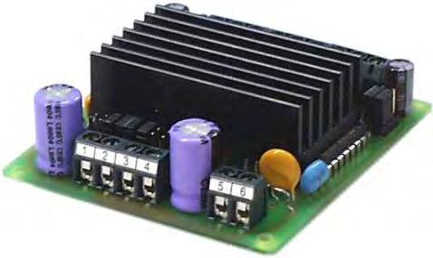
3 EM- STEPPER MOTOR CONTROLLER 40V FETURES Bipolar chopper Wide operating voltage range Full and half step operation -settable phase currents uxiliary oscillator cceleration ramp, 3-speed Self recovery fuse Rail mounting base fittable EM- is bipolar-chopper type stepper motor controller. Bipolar operation suits most stepper motors and provides the best torque. Phase current is set to desired level using chopping type current limit. The phase current ( current limit ) can be set in seven different levels using jumpers. wide phase current set range makes it possible to use the device with several different motors. EM-M also utilizes steady state current hold, in other words when the motor is stopped the controller decreases phase current, this feature reduces both the motor and controller thermal loss. Two steady state current hold modes are settable. The controller features an auxiliary oscillator, which has fifteen preprogrammed frequencies. The frequency is set with four control inputs. uxililary oscillator in EM- has also an acceleration ramp feature, which can be used to change frequencies flexibly, so that the motor will start up reliably even at high frequencies. There are three acceleration ramp intervals, that can also be bypassed. The inputs operate with so called negative logic, in other words the inputs are activated with connecting the input to ground, the inputs also work with TTL-logic level control. The power state of EM- has thermal protection for overload, the device has also self recovery fuse that protects the controller from over current and reversed input voltage polarity. TECHNICL DT: EM- BLOCK DIGRM Operating voltage -40Vdc Idle current approx. 40m / (0m shutdown "0") Current set 0.5; 0.3; 0.5; 0.3; 0.5; 0.9; and.0 Steady state I hold approx. 35 or % of current set Voltage loss 3V when Im= Fuse self recovery. ux. osc. freq. 0, 50, 00, 00, 300 Hz 400, 00, 800, 000 Hz.5; ;.5; 3; 3.5; 4 khz Freq. precision typ. % Digital control "off" when Uin 4-30V or open "on" when Uin 0-V Step freq. max. 9kHz Operating temp C Dimensions x5x5mm Weight approx. 00g FULL- / HLF STEP SHUTDOWN DIRECTION STEP UX OSCILLTOR STEP LOGIC PTC FUSE + REGULTION - STEDY STGE CURRENT HOLD CCELERTION RMP POWER STGE CURRENT LIMIT PHSE CURRENT INPUT 5 3 SM 4
4 OPERTING INSTRUCTIONS EM- Supply voltage -40Vdc filtered. Control inputs are activated using switches, or 0-5V voltage signals, or NPN-open collector outputs. 0V gnd full / half direction step input shutdown speed speed speed 3 speed 4 Current, steady state current hold and ramp are set with jumpers STEP: - full step switch on or 0V half step switch off or 5V DIRECTION: - Forward switch on or 0V Backwards switch off or 5V STEP-INPUT: - TTL or 0-5V pulse, trigs with falling edge SHUTDOWN: - switch on or 0V CHOOSING UXILIRY OSCILLTOR FREQUENCIES: - activate with switch on or 0V steady state current hold current set ramp mm mm CURRENT SET Phase current setting map ' B B' stepper motor 59mm 5mm supply 0V supply -4V STEDY STTE CURRENT HOLD When the motor is not run the current set changes to current hold. Steady state current hold is set either to 33% or % 33% % UXILIRY OSCILLTOR The aux. oscillator produces preprogrammed frequencies, the frequencies are set with four digital inputs. The aux. oscillator also features ramp, that can be used to change frequencies flexible, with better motor start up. Small frequencies change directly, but frequencies above 400 Hz change with slope. CUTION! ux. oscillator cannot be used with pulse input at the same time. ramp off ( direct ) fast ( Hz 0.s.) middle ( Hz 0.4s.) slow ( Hz 0.s.) freq./hz stop switches 3 4
5 EM-38 STEPPER MOTOR DRIVER 3-4V microstepping and presettable function inputs FETURES - Bibolar chopper -, /, /4.../4 steps - Four preset function inputs - PNP or TTL control - Quiet run current control - cceleration / deceleration ramps - DIN-rail base mountable EM-38 is a bipolar-chopper type microstepping steppermotor controller. The bipolar operation principle suits most stepper motors and provides the best torque. The microstepping function also enables great performance at low rpm. The stepping and current regulation has been synchronized, giving a smooth and quiet operation. There are different stepping options to choose from, ranging from full- to /4-step operation. This provides various possibilities for different speed applications. The controller has its own auxiliary oscillator, which can be used for pre-set speed driving. The pre-set speeds can be activated by using 4 digital function inputs. The oscillator features an acceleration ramp function, which allows frequencies to be altered flexibly. The motor will also start up reliably even to higher frequencies and it is possible to shift to the desired velocity with out pace drop. The auxiliary oscillator incorporates an indexing part, which offers the possibility of running presettable operational sequences. These secuences can be activated with the 4 digital inputs. The sequence is a movement with selected speed, direction and distance (as steps). ll the inputs are activated with positive logic commands. So the commands and functions are activated by connecting the input to a positive voltage. Control can also be done with TTL-logic level commands. ll of the controller settings are made digitally, using the separate setting device, EM-3 Interface Unit. With this device the settings are easily copied to an other or even to multiple controllers. EM-38 BLOCK DIGRM Operating voltage Idle current Current settings uxliary oscillator Frequency accuracy Ramp adjust Control level Max. step freq. Operating temp. Dimensions Weight -35Vdc n. 0m ( step 0. ) Hz typ. 0.5% 0.-5s ( 0 to 0000Hz ) "on" when Uin 4-30V "off" when Uin 0-V or open 5kHz 0-50 C 8x.5x5mm 00g 4 3 5V max. 0m DISBLE DIRECTION STOP / RESET STEP IN UXIRY STEP OSCILLTOR 0,5 PTC FUSE STEPPING LOGIC usteps...4 REGULTION POWER STGE PHSE CURRENT SETTING SM 5 B B STRT / STOP RMP CONTROL INPUT CONFIGURTION ll control inputs 4kohm (step in = kohm) 0kohm INDEX COUNTER ND SPEED MEMORY FOR PRE-SET FUNCTIONS SERIL PORT FOR PRMETER SETTING
6 CONNECTIONS Operating voltage -35Vdc, ripple smaller than 0%. The card has no internal fuse. The use of an external fuse is recommended. Incorrect supply polarity can damage the controller. ll control inputs work with positive control 4-30V. Inputs can be controlled with PLC or TTL signals. 5V auxiliary output (terminal ) can source max. 0m. CONTROL -inputs STEP IN is the input for stepping pulses. One steps is done with the positive edge of the input pulse. DIR/STOP/RESET input is normally used to choose the rotational direction. If preset functions are used (terminal 8 to ) this input can act as a stop input, and if preset sequence is used it will also reset the sequence counter. This input is triggered with up going pulse edge. DISBLE will shut down power stage and hold it disabled, this input has the highest priority. But it will not reset a sequence. So it is recommended to stop and reset functions before releasing disable to avoid any possible uncontrolled startup. PRESET IN -4 are presettable function inputs. These are used to activate chosen preset function. Function parameters include speed, direction, and distance in steps. If stepping distance is chosen to be zero, the drive will be continued as long as input is selected or STOP is activated. In other words the function works as preset speed driving. PRMETER SETTING The card settings are made with a EM-3 Interface Unit or Ementool Lite PC soft-ware and EM-8 USB-dongle. EM-3 is connected to a red connector on the card. t first it will display the cards type and program version. nswering yes for LOD and EDIT alternative the cards parameters are retrieved and displayed as a list that can be browsed with the arrow keys. djustment is done with +/- keys. The adjusted parameters are saved by pressing the SVE key for about seconds. fter this, a notification will appear that that the new values has been SEND and SVED. By choosing the MONITOR function, you can monitor the cards operation. Status LED codes continuous - power on disable input on - slow blinking temp. limit disable - fast blinking,5mm 4mm status LED -35V 0V gnd ' 5mm 59mm stepper motor dir / reset in step in disable EM B B' preset in preset in preset in 3 preset in 4 5V 0m out EM-3 PRMETER EFFECT.The stepping mode determines how much motor moves when card receives a step pulse. The most precise results are achieved with so called micro-stepping (partial step) setting and the highest possible resolution is /4-motor step agains one incoming step pulse..ramp setting is common for acceleration- and deceleration. Ramp is in use with preset functions. 3.The current drop function limits the current to the set percentace during the rest-stage. This reduces the amount of the heat that motor has to dissipate. Notice. Lower values than 00% can reduce precision in micro-stepping driving. 4. Phase current limiting during the drive. 5. and. are not in use..-. These are to determine preset functions which are activated with PRESET IN # inputs. There are four preset functions available to be determined..-0. Parameters to select the preset direction..-4. Parameters to set the stepping frequency = speed 5.-. Parameters for stepping amount = distance. For example: Par.5 set to 393 and Par. set to 4 will result in 4393 steps total when terminal 8 (preset in ) is activated. Notice. The movement is in ratio to the used stepping mode. With /4 mode the movement is smallest, that is: 4393/4 = /4 full steps MONITORBLE VLUES. last activated preset function. sequence step down counter to zero 3. Step counter. Reset with a new sequence. PRMETERS of EM-38 prog. default values in brackets.. Stepping mode ( 0- ) [) 0 = full step = half step = quarter step 3 = /8 step 4 = / step 5 = /3 step = /4 step. Ramp time 0.-5s ( -50 ) [0] 3. Current s after stop ( -4 ) [4]. 00% ( = normal ). 50% ( reduced ) 3. 5% ( reduced ) 4. 0% ( current disabled ) 4. Phase current 0.-3 ( -30 ) [0] 5. not in use (0-). not in use (0-) Preset run directions. preset. 0=fwd =rev [0] 8. preset. 0=fwd =rev [] 9. preset 3. 0=fwd =rev [0] 0.preset 4. 0=fwd =rev [] Preset run frequencies. preset Hz ( ) [30]. preset Hz ( ) [30] 3. preset Hz ( ) [00] 4. preset Hz ( ) [00] Index run counting values step Setting 0= continuous run 5. preset ( 0-999) [0]. preset x 0³ ( 0-000) [0]. preset ( 0-999) [0] 8. preset x 0³ ( 0-000) [0] 9. preset ( 0-999) [0] 0. preset x 0³ ( 0-000) [0]. preset ( 0-999) [0]. preset x 0³ ( 0-000) [0] 3. min start freq Hz ( ) [0]
7 EM-3 STEPPER MOTOR MICROSTEPPING CONTROLLER UNIT -45V FETURES: Bipolar chopper Wide supply voltage range Full-, half-, quarter-, and /8-step operation 8-programmable phase currents uxiliary oscillator cceleration- and braking ramp Self recovery fuse Very high efficiency Low heat dissipation Rail mounting base available EM-3 is bipolar-chopper type stepper motor controller. Bipolar operation suits most stepper motors and provides the best torque. The microstepping feature gives high performance also at low rpm. The power stage is mosfet-type so it runs with very high efficiency. There are four stepping modes: full, half, quarter and /8. Desired mode is set with two control inputs. The phase current ( current limit ) can be set in eight different levels using dip-switches. wide phase current set range makes it possible to use the device with several different motors. The controller features an auxiliary oscillator, which has preprogrammed frequencies. The frequency is set with three control inputs. uxililary oscillator in EM-3 has also an acceleration ramp feature, which can be used to change frequencies flexibly, so that the motor will start up reliably even at high frequencies. The acceleration ramp time is set with a trim. The inputs operate with so called positive logic, in other words the inputs are activated with connecting the input to positive voltage. The inputs also work with TTL-logic level control. The power state of EM-3 has self recovery fuse that protects the controller from over current and reversed input voltage polarity. TECHNICL DT: Operating voltage -45Vdc Idle current approx. 5m (enable "0") Current set 0.5;,0;.5;.0;.5; 3.0; 3,5 and 4.0 Voltage loss V when Im= Fuse 4 self recovery. ux. osc. freq. 00, 500, 000, 000 Hz 3000, 5000, 8000 Hz Ramp speed 0,...3s ( Hz) ux. freq. precision better than 0,5% Digital control "on" when Uin 4-30V "off" when Uin 0-V Step freq. max. 5 khz Operating temp C Dimensions 8x3x35mm Weight approx. 90g V ENBLE STEP MODE STEP MODE DIRECTION STEPPING UX. OSCILLTOR EM-3 BLOCK DIGRM STEPPING LOGIC REGULTION CCELERTION RMP 4 PTC FUSE SELECT POWER STGE CURRENT SET PHSE CURRENT INPUT B SM
8 EM-3 WIRING ND INSTLLTION Supply voltage -45Vdc, ripple less than 0% Make sure that the current feed capability of the voltage source is adequate for the application. The undervoltage situation can cause undesired effects for the function. The phase current is set with PHSE CURRENT switch ( see the table below ). Notice that the motor do not always need the nominal phase current. Often the motor works better with lower than the nominal current. Find the best current for your application, but do not exceed the nominal current of the motor. Control inputs are activated using switches or voltage signal. Driver has a positive control logic V = "on", 0-V or OPEN = "off" There are four stepping modes : full, half, /4 and /8. The full-step is good for higher speeds. The /8-step gives best resolution on positioning use, and also the smoothest run on low speeds. Stepping mode is selected with STEP MODE inputs & B ( look at table below ). If used with external stepping frequency source, connect frequency signal to STEP PULSE input. Incoming pulse level should be 4-30V, frequency max.5khz and minimum pulse lenght 5us. Internal stepping source (aux. oscillator) is set with UX. OSC. inputs, and 3 ( see the table ). ux. oscillator includes also the acceleration RMP. It gives a smooth start towards the selected frequency. The ramp time can be adjusted from 0. to 3sec. The UX. OSC. frequencies and the RMP time are based on 0MHz crystal frecuency. The chrystal can be changed to be anything between 4...0MHz. The UX. OSC. frequencies and ramp time are changed in the same proportion. ENBLE has the highest priority. NOTE. If ENBLE input is "off" the output stage is turned off, (output current is off) and also the UX. OSC is reset. So every time when the ENBLE input is turned "on" the UX. OSC. starts with the acceleration ramp. DIRECTION input is used to change the rotating direction. Direction change does not include the RMP function in it self. But if it is used with the ENBLE input the ramp and the smooth direction change can be achieved. gnd (0V) aux. osc in aux. osc in aux. osc in 3 step mode in B step mode in direction step pulse in enable 5V max 0m STEP MODE SET aux. oscillator acceleration ramp set: from 0, to 3seconds. crystal 0MHz phase current set full step: input and B "off" half step: input "on", B "off" /4 step: input "off", B"on" /8 step: input and B "on" FUSE supply link on...3v link off...45v "on" "off" 4 mm mm PHSE CURRENT SET 0.5 all "off".0 and 4 "on", others "off".5 and 5 "on", others "off".0,,4,5 "on", others "off".5 3 and "on", others "off" 3.0,3,4, "on", others "off" 3.5,3,5, "on", others "off" 4.0 all "on" supply -3V supply 0V ' B B' stepper motor 80 mm 8 mm UX. OSCILLTOR FREQ. (with 0MHz crystal) stop all aux. osc. input "off" 00Hz in "on", others "off" 500Hz in "on", others "off" 000Hz in, "on", others "off" 000Hz in3 "on", others "off" 3000Hz in,3 "on", others "off" 5000Hz in,3 "on", others "off" 8000Hz all aux. osc. input "on"
9 EM-8- STEPPER MOTOR MICROSTEPPING CONTROLLER UNIT 0-80V FETURES: Bipolar chopper Wide supply voltage range Full-, half-, quarter-, and /8-step operation 8-programmable phase currents uxiliary oscillator cceleration- and braking ramp Power reduction Very high efficiency Low heat dissipation Rail mounting base available EM-8- is bipolar-chopper type stepper motor controller. Bipolar operation suits most stepper motors and provides the best torque. The microstepping feature gives high performance also at low rpm. The power stage is mosfet-type so it runs with very high efficiency. There are four stepping modes: full, half, quarter and eighth. Desired mode is set with two control inputs. The phase current ( current limit ) can be set in eight different levels using dip-switches. wide phase current set range makes it possible to use the device with several different motors. utomatic power reduction will drop phase current when stepping pulses stop coming. The controller features an auxiliary oscillator, which has preprogrammed frequencies. The frequency is set with three control inputs. uxililary oscillator in EM-8- has also an acceleration ramp feature, which can be used to change frequencies flexibly, so that the motor will start up reliably even at high frequencies. The acceleration ramp time is set with a trim. The inputs operate with so called positive logic, in other words the inputs are activated with connecting the input to positive voltage. The inputs also work with TTL-logic level control. TECHNICL DT: EM-8 BLOCK DIGRM Operating voltage 0-80Vdc Idle current approx. 5m (enable "0") Current set 0,8;,4; ;, 3,; 3,8; 4,4; 5,0 Voltage loss V when Im= ux. osc. freq. 00, 500, 000, 000 Hz 3000, 5000, 8000 Hz Ramp speed 0,...3s ( Hz) ux. freq. precision better than 0,5% Digital control "on" when Uin 4-30V "off" when Uin 0-V or open Stepping options,/,/4,/8 step Power reduction -0% Power reduction delay 00ms from last pulse Step freq. max. 5 khz Operating temp C Dimensions 90x0x30mm Weight approx. 80g RUN/STOP STEP MODE STEP MODE DIRECTION STEPPING UX OSCILLTOR CONTROL GND REG STEPPING LOGIC POWER REDUCTION POWER STGE CURRENT SET PHSE CURRENT CCELERTION RMP B SM
10 EM-8- WIRING ND INSTLLTION Supply voltage 0-80Vdc, ripple less than 0% Make sure that the current feed capability of the voltage source is adequate for the application. The undervoltage situation can cause undesired effects for the function. The phase current is set with PHSE CURRENT switch ( see the table below ). Notice that the motor do not always need the nominal phase current. Often the motor works better with lower than the nominal current. Find the best current for your application, but do not exceed the nominal current of the motor. Control inputs are activated using switches or voltage signal. Driver has a positive control logic V = "on", 0-V or OPEN = "off" There are four stepping modes : full, half, /4 and /8. The full-step is good for higher speeds. The /8-step gives best resolution on positioning use, and also the smoothest run on low speeds. Stepping mode is selected with STEP MODE inputs & B ( look at table below ). If used with external stepping frequency source, connect frequency signal to STEP PULSE input. Incoming pulse level should be 4-30V, frequency max.5khz and minimum pulse lenght 5us. Internal stepping source (aux. oscillator) is set with UX. OSC. inputs, and 3 ( see the table ). ux. oscillator includes also the acceleration RMP. It gives a smooth start towards the selected frequency. The ramp time can be adjusted from 0. to 3sec. The UX. OSC. frequencies and the RMP time are based on 0MHz crystal frecuency. The chrystal can be changed to be anything between 4...0MHz. The UX. OSC. frequencies and ramp time are changed in the same proportion. ENBLE has the highest priority. NOTE. If ENBLE input is "off" the output stage is turned off, (output current is off) and also the UX. OSC is reset. So every time when the ENBLE input is turned "on" the UX. OSC. starts with the acceleration ramp. DIRECTION input is used to change the rotating direction. Direction change does not include the RMP function in it self. But if it is used with the ENBLE input the ramp and the smooth direction change can be achieved. gnd (0V) aux. osc in aux. osc in aux. osc in 3 step mode in B step mode in direction step pulse in enable 5V max 0m STEP MODE SET aux. oscillator acceleration ramp set: from 0, to 3seconds. crystal 0MHz phase current set full step: input and B "off" half step: input "on", B "off" /4 step: input "off", B"on" /8 step: input and B "on" off power reduction on "on" "off" 0 mm 0 mm PHSE CURRENT SET 0.8 all "off".4 and 4 "on", others "off".0 and 5 "on", others "off".,,4,5 "on", others "off" 3. 3 and "on", others "off" 3.8,3,4, "on", others "off" 4.,3,5, "on", others "off" 5.0 all "on" supply 0-80V supply 0V ' B B' stepper motor 85 mm 90 mm UX. OSCILLTOR FREQ. (with 0MHz crystal) stop all aux. osc. input "off" 00Hz in "on", others "off" 500Hz in "on", others "off" 000Hz in, "on", others "off" 000Hz in3 "on", others "off" 3000Hz in,3 "on", others "off" 5000Hz in,3 "on", others "off" 8000Hz all aux. osc. input "on"

11 EM-34 STEPPER MOTOR DRIVER -4V microstepping and presettable function inputs FETURES - Bibolar chopper -, /, /4.../4 steps - Four preset function inputs - PNP or TTL control - Quiet run current control - cceleration / deceleration ramps - DIN-rail base mountable EM-34 is a bipolar-chopper type microstepping steppermotor controller. The bipolar operation principle suits most stepper motors and provides the best torque. The microstepping function also enables great performance at low rpm. The stepping and current regulation has been synchronized, giving a smooth and quiet operation. There are different stepping options to choose from, ranging from full- to /4-step operation. This provides various possibilities for different speed applications. The controller has its own auxiliary oscillator, which can be used for pre-set speed driving. The pre-set speeds can be activated by using 4 digital function inputs. The oscillator features an acceleration ramp function, which allows frequencies to be altered flexibly. The motor will also start up reliably even to higher frequencies and it is possible to shift to the desired velocity with out pace drop. The auxiliary oscillator incorporates an indexing part, which offers the possibility of running presettable operational sequences. These secuences can be activated with the 4 digital inputs. The sequence is a movement with selected speed, direction and distance (as steps). ll the inputs are activated with positive logic commands. So the commands and functions are activated by connecting the input to a positive voltage. Control can also be done with TTL-logic level commands. ll of the controller settings are made digitally, using the separate setting device, EM-3 Interface Unit. With this device the settings are easily copied to an other or even to multiple controllers. EM-34 BLOCK DIGRM Operating voltage Idle current Current settings uxliary oscillator Frequency accuracy Ramp adjust Control level Max. step freq. Operating temp. Dimensions Weight -35Vdc n. 0m 0. - ( step 0. ) Hz typ. 0.5% 0.-5s ( 0 to 0000Hz ) "on" when Uin 4-30V "off" when Uin 0-V or open 5kHz 0-50 C 8x.5x5mm 00g 4 3 5V max. 0m DISBLE DIRECTION STOP / RESET STEP IN UXIRY STEP OSCILLTOR 0,5 PTC FUSE STEPPING LOGIC usteps...4 REGULTION POWER STGE PHSE CURRENT SETTING SM 5 B B STRT / STOP RMP CONTROL INPUT CONFIGURTION ll control inputs 4kohm (step in = kohm) 0kohm INDEX COUNTER ND SPEED MEMORY FOR PRE-SET FUNCTIONS SERIL PORT FOR PRMETER SETTING
12 CONNECTIONS Operating voltage -35Vdc, ripple smaller than 0%. The card has no internal fuse. The use of an external fuse is recommended. Incorrect supply polarity can damage the controller. ll control inputs work with positive control 4-30V. Inputs can be controlled with PLC or TTL signals. 5V auxiliary output (terminal ) can source max. 0m. CONTROL -inputs STEP IN is the input for stepping pulses. One steps is done with the positive edge of the input pulse. DIR/STOP/RESET input is normally used to choose the rotational direction. If preset functions are used (terminal 8 to ) this input can act as a stop input, and if preset sequence is used it will also reset the sequence counter. This input is triggered with up going pulse edge. DISBLE will shut down power stage and hold it disabled, this input has the highest priority. But it will not reset a sequence. So it is recommended to stop and reset functions before releasing disable to avoid any possible uncontrolled startup. PRESET IN -4 are presettable function inputs. These are used to activate chosen preset function. Function parameters include speed, direction, and distance in steps. If stepping distance is chosen to be zero, the drive will be continued as long as input is selected or STOP is activated. In other words the function works as preset speed driving. PRMETER SETTING The card settings are made with a EM-3 Interface Unit or Ementool Lite PC soft-ware and EM-8 USB-dongle. EM-3 is connected to a red connector on the card. t first it will display the cards type and program version. nswering yes for LOD and EDIT alternative the cards parameters are retrieved and displayed as a list that can be browsed with the arrow keys. djustment is done with +/- keys. The adjusted parameters are saved by pressing the SVE key for about seconds. fter this, a notification will appear that that the new values has been SEND and SVED. By choosing the MONITOR function, you can monitor the cards operation. Status LED codes continuous - power on disable input on - slow blinking temp. limit disable - fast blinking,5mm 4mm -35V V EM-34 ' stepper motor B B' 8mm 8mm 8 5V 0m out preset in preset in preset in 3 preset in 4 dir / reset in step in disable EM-3 gnd status LED PRMETER EFFECT.The stepping mode determines how much motor moves when card receives a step pulse. The most precise results are achieved with so called micro-stepping (partial step) setting and the highest possible resolution is /4-motor step agains one incoming step pulse..ramp setting is common for acceleration- and deceleration. Ramp is in use with preset functions. 3.The current drop function limits the current to the set percentace during the rest-stage. This reduces the amount of the heat that motor has to dissipate. Notice. Lower values than 00% can reduce precision in micro-stepping driving. 4. Phase current limiting during the drive. 5. and. are not in use..-. These are to determine preset functions which are activated with PRESET IN # inputs. There are four preset functions available to be determined..-0. Parameters to select the preset direction..-4. Parameters to set the stepping frequency = speed 5.-. Parameters for stepping amount = distance. For example: Par.5 set to 393 and Par. set to 4 will result in 4393 steps total when terminal 8 (preset in ) is activated. Notice. The movement is in ratio to the used stepping mode. With /4 mode the movement is smallest, that is: 4393/4 = /4 full steps MONITORBLE VLUES. last activated preset function. sequence step down counter to zero 3. Step counter. Reset with a new sequence. PRMETERS of EM-34 prog. default values in brackets.. Stepping mode ( 0- ) [] 0 = full step = half step = quarter step 3 = /8 step 4 = / step 5 = /3 step = /4 step. Ramp time 0.-5s ( -50 ) [0] 3. Current s after stop ( -4 ) [4]. 00% ( = normal ). 50% ( reduced ) 3. 5% ( reduced ) 4. 0% ( current disabled ) 4. Phase current 0.- ( -0 ) [0] 5. not in use ( 0-). not in use ( 0- ) Preset run directions. preset. 0=fwd =rev [0] 8. preset. 0=fwd =rev [] 9. preset 3. 0=fwd =rev [0] 0.preset 4. 0=fwd =rev [] Preset run frequencies. preset Hz ( ) [30]. preset Hz ( ) [30] 3. preset Hz ( ) [00] 4. preset Hz ( ) [00] Index run counting values step Setting 0= continuous run 5. preset ( 0-999) [0]. preset x 0³ ( 0-000) [0]. preset ( 0-999) [0] 8. preset x 0³ ( 0-000) [0] 9. preset ( 0-999) [0] 0. preset x 0³ ( 0-000) [0]. preset ( 0-999) [0]. preset x 0³ ( 0-000) [0] 3. min start freq Hz ( ) [0]
Testra Corporation ss483 Series Microstepping Motor Driver. Specifications Sep SoftStep FIRMWARE FEATURES
 SoftStep The New Art of Stepper Motor Control With SoftStep you get the benefits of ultra smooth microstepping regardless of your selected step size. The intelligent on board processor treats the input
TECHNICAL SPECIFICATIONS ELECTROMEN BRUSHLESS DC MOTOR SPEED CONTROLLERS
 TEHNIL SPEIFITIONS ELETROMEN RUSHLESS D MOTOR SPEED ONTROLLERS Page 3of 28 EM-240 RUSHLESS D-MOTOR ONTROLLER 12-24V 1.5 FETURES: Hall sensor supply and input Open or closed loop activity ontrolled direction
TECHNICAL SPECIFICATIONS ELECTROMEN BRUSH MOTOR POSITIONING CONTROLLERS
 TECHNICAL SPECIFICATIONS ELECTROMEN BRUSH MOTOR POSITIONING CONTROLLERS EM-4-SAF POSITIONING DRIVER -4V 4A FEATURES - analog feedback - multiple dynamic settings - solid state power stage - one or two
DM8010 tm. Hardware Reference Manual. Document Revision B3 May 16, 2018
 tm Hardware Reference Manual Document Revision B3 May 16, 2018 MICROKINETICS CORPORATION 3380 Town Point Drive Suite 330 Kennesaw, Georgia 30144 Tel: (770) 422-7845 Fax: (770) 422-7854 Table Of Contents
TECO F510 Inverter. Quick Start Guide. Step 1. Supply & Motor connection
 Quick Start Guide TECO F510 Inverter This guide is to assist you in installing and running the inverter and verify that it is functioning correctly for it s main and basic features. For detailed information
Contents. USER MANUAL NI ISM-7400 Integrated Stepper
 USER MANUAL NI ISM-7400 Integrated Stepper This manual describes the NI ISM-7400 integrated stepper. It describes electrical and mechanical characteristics of the devices, as well as I/O functionality.
CHAPTER 5 DESCRIPTION OF PARAMETER SETTINGS
 CHAPTER DESCRIPTION OF PARAMETER SETTINGS.1 Group 0: User Parameters 0-00 Identity Code of AC Drive Factory setting: d# Settings None V HP 1/4 1/2 1 2 3 11V/230V d0 d2 d4 d6 d8 460V -- -- -- d3 d d7 d9
Functional description of BSD-01v2 Module
 Functional description of BSD-01v2 Module The BSD-01v2 module is a complete microstepping driver with built-in translator suitable for driving bipolar step motors from 15 to 750mA and up to 30V. It comes
NJM37717 STEPPER MOTOR DRIVER
 STEPPER MOTOR DRIVER GENERAL DESCRIPTION PACKAGE OUTLINE NJM37717 is a stepper motor diver, which consists of a LS-TTL compatible logic input stage, a current sensor, a monostable multivibrator and a high
DUAL STEPPER MOTOR DRIVER
 DUAL STEPPER MOTOR DRIVER GENERAL DESCRIPTION The is a switch-mode (chopper), constant-current driver with two channels: one for each winding of a two-phase stepper motor. is equipped with a Disable input
TECHNICAL SPECIFICATIONS ELECTROMEN DC BRUSH MOTOR SPEED CONTROLLERS
 TECHNICAL SPECIFICATIONS ELECTROMEN DC BRUSH SPEED CONTROLLERS EM70 DC CONTROLLER V.A FEATURES: quadrants controlled direction change brake adjustable current limit acceleration and deceleration ramp
Hardware Manual PDO 3540
 Hardware Manual PDO 0 Step Motor Driver w/ Oscillator Step Motor Driver PDO 0 CURRENT (BASE = A) MOTOR DIR+ DIR STEP+ STEP EN+ EN SPEED+ SPEED- TACH+ TACH CW WPR CCW JOYSTICK EXT SPEED 0% IDLE POWER OSC
MSD Microstepping Motor Drive
 ELECTRIC LINEAR MOTION PRODUCTS MSD Microstepping Motor Drive USER'S MANUAL TOL-O-MATIC, INC Excellence in Motion 3600-4053C Copyright 1998 Tol-O-Matic, Incorporated. All rights reserved. Axidyne and Tol-O-Matic
3DM phase Digital Stepper Drive
 3DM2283 3-phase Digital Stepper Drive 150-220VAC, 0.5-8.2A peak, Auto-configuration, Low Noise Anti-Resonance provides optimal torque and nulls mid-range instability Motor auto-identification and parameter
Data Sheet. Stepper Motor Drive Boards. Features
 Data Pack B Issued March 0-6 Data Sheet Stepper Motor Drive Boards Unipolar stepper motor drive board (RS stock no. 7-6) and bipolar stepper motor drive board (RS stock no. -906) The unipolar drive board
HITACHI. L100-M Series Inverter Quick Reference Guide. Hitachi Industrial Equipment Systems Co., Ltd. Single-phase Input 100V Class
 HITACHI L1-M Series Inverter Quick Reference Guide Single-phase Input 1V Class Hitachi Industrial Equipment Systems Co., Ltd. Manual No. NB5741XD December 23 Caution: Be sure to read the L1 Inverter Manual
DeviceCraft Revision #1 11/29/2010
 DeviceCraft Revision #1 11/29/2010 DC Wiper Motor H-Bridge Servo / Speed Controller P/N 1020 Features: Dip Switch selectable mode of operation Both PID servo or speed controller Forward/Reverse operation
For more information on these functions and others please refer to the PRONET-E User s Manual.
 PRONET-E Quick Start Guide PRONET-E Quick Start Guide BASIC FUNCTIONS This guide will familiarize the user with the basic functions of the PRONET-E Servo Drive and assist with start up. The descriptions
CL86T. 24~80VDC, 8.2A Peak, Closed-loop, No Tuning. Descriptions. Closed-loop. Stepper. Applications. Datasheet of the Closed-loop Stepper CL86T
 CL86T Closed-loop Stepper 24~80VDC, 8.2A Peak, Closed-loop, No Tuning Closed-loop, eliminates loss of synchronization Broader operating range higher torque and higher speed Reduced motor heating and more
Functional description of BSD-01 Module. Features
 Functional description of BSD-01 Module The BSD-01 module is a complete microstepping driver with built-in translator suitable for driving bipolar step motors up to 750mA and 30V. It operates in Full-,
User's Manual. Step Motor Driver
 9/7/99 7080.ai User's Manual 7080 Step Motor Driver Applied Motion Products, Inc. 0 Westridge Drive Watsonville, CA 95076 Tel (8) 76-6555 (800) 55-609 Fax (8) 76-65 s drives controls Technical Specifications
ORIENTAL MOTOR GENERAL CATALOG
 ORIENTL MOTOR GENERL CTLOG STEPPING MOTORS 5-PHSE STEPPING MOTOR ND MICROSTEP DRIVER PCKGE RFK Features B-64 Specifications B-67 Speed vs.torque Characteristics B-68 Dimensions B-69 List of Motor and Combinations
30-80V, 8.2A Peak, No Tuning, Nulls loss of Synchronization
 2-phase Hybrid Servo Drive 30-80V, 8.2A Peak, No Tuning, Nulls loss of Synchronization Closed-loop, eliminates loss of synchronization Broader operating range higher torque and higher speed Reduced motor
Stepper Motor Driver CW8060
 Stepper Motor Driver CW8060 CW8060 1. Introduction Descriptions The CW8060 driver is a cost-effective and high performance stepping driver. The design is based on an advanced control technology. It applies
High Performance Microstep Systems
 P315/P315X High Performance Microstep Systems Description Common Features Torques from 65 to 3, oz-in. with speeds to 3, RPM continuous. Dip switch selectable resolutions up to 5,8 steps per revolution.
NJM3777 DUAL STEPPER MOTOR DRIVER NJM3777E3(SOP24)
") DUAL STEPPER MOTOR DRIER GENERAL DESCRIPTION The NJM3777 is a switch-mode (chopper), constant-current driver with two channels: one for each winding of a two-phase stepper motor. The NJM3777 is equipped
DUAL STEPPER MOTOR DRIER GENERAL DESCRIPTION The NJM3777 is a switch-mode (chopper), constant-current driver with two channels: one for each winding of a two-phase stepper motor. The NJM3777 is equipped
DMX-K-DRV-17 Integrated Step Motor Driver & Basic Controller
 DMX-K-DRV-17 Integrated Step Motor Driver & Basic Controller DMX-K-DRV-17 Manual - 1 - rev 1.35 COPYRIGHT 2015 ARCUS, ALL RIGHTS RESERVED First edition, June 2007 ARCUS TECHNOLOGY copyrights this document.
NX series Constant and variable torque Variable Speed Drives for induction motors
 Honeywell All in One Application Manual NX series Constant and variable torque Variable Speed Drives for induction motors Subject to changes without notice CONTENTS NX "All in One" APPLICATION MANUAL INDEX
Hardware Manual. STR4 & STR8 Step Motor Drives
 Hardware Manual STR4 & STR8 Step Motor Drives 92-3J 92-3J Contents Introduction... 3 Features... 3 Block Diagram... 4 Getting Started... 5 Mounting the Drive... 6 Connecting the Power Supply... 6 Drive
CHAPTER AC DRIVE PARAMETERS. In This Chapter...
 CHAPTER AC DRIVE 4 PARAMETERS In This Chapter... GS2 Parameter Summary....................4 2 Detailed Parameter Listings.................4 11 Motor Parameters........................4 11 Ramp Parameters.........................4
A3982. DMOS Stepper Motor Driver with Translator
 OUT2A SENSE2 VBB2 OUT2B ENABLE PGND PGND CP1 CP2 VCP VREG MS1 1 2 3 4 5 6 7 8 9 10 11 12 Charge Pump Reg Package LB Translator & Control Logic AB SO LUTE MAX I MUM RAT INGS Load Supply Voltage,V BB...35
Stepper Motor Driver CW230
 Stepper Motor Driver CW230 1. Introduction Descriptions The CW230 driver is a cost-effective and high performance stepping driver. The design is based on an advanced control technology. It applies to two-phase
Si3540 Programmable Step Motor Drive
 44 Westridge Dr. Watsonville, CA 9576 831/761-6555 8/525-169 FAX 831/761-6544 Si354 Programmable Step Motor Drive 38 Si354 Programmable Step Motor Drive Features Si, Si Command anguage (SC) or SiNet Hub
GS1 Parameter Summary Detailed Parameter Listings...4 9
 CHAPTER AC DRIVE 4 PARAMETERS Contents of this Chapter... GS1 Parameter Summary...............................4 2 Detailed Parameter Listings..............................4 9 Motor Parameters.........................................4
DMX-K-DRV-23 Integrated Step Motor Driver & Basic Controller
 DMX-K-DRV-23 Integrated Step Motor Driver & Basic Controller DMX-K-DRV-23 Manual - 1 - rev 1.35 COPYRIGHT 2013 ARCUS, ALL RIGHTS RESERVED First edition, June 2007 ARCUS TECHNOLOGY copyrights this document.
Datasheet of the MEZ Stepper Servo Drive MEZ 2D VDC, 8.2A Peak, Closed-loop, No Tuning. Version
 Datasheet of the MEZ Stepper Servo Drive MEZ D880 4-75VDC, 8.A Peak, Closed-loop, No Tuning Version 0.1.1 http://www.motionking.com Features Step and direction control Closed position loop for no loss
Industrial motor controller for brushed DC motors 24 VDC
 Industrial motor controller for brushed DC motors 24 VDC Design for output currents up to 5 A Control with the following functions: - reversal of direction of rotation - open-loop speed control (external)
vacon nx all in one application manual ac drives Phone: Fax: Web: -
 vacon nx ac drives all in one application manual vacon 1 INDEX Document ID:DPD00903A Revision release date: 30.3.2012 1. Basic Application...5 1.1. Introduction...5 1.1.1. Motor protection functions in
Integrated Easy Servo
 ies 1706 Integrated Easy Servo Motor + Drive + Encoder, 18 32VDC, NEMA17, 0.6Nm Features Easy servo control technology to combine advantages of open loop stepper systems and brushless servo systems Closed
ES86 Series Closed-loop Stepper Drive + Motor System (Drive+ Motor/Encoder)
") ES86 Series Closed-loop Stepper Drive + Motor System (Drive+ Motor/Encoder) Traditional stepper motor drive systems operate open loop providing position control without feedback. However, because of this,
ES86 Series Closed-loop Stepper Drive + Motor System (Drive+ Motor/Encoder) Traditional stepper motor drive systems operate open loop providing position control without feedback. However, because of this,
Stepper Motor Drive Circuit
 Stepper Motor Drive Circuit FEATURES Full-Step, Half-Step and Micro-Step Capability Bipolar Output Current up to 1A Wide Range of Motor Supply Voltage 10-46V Low Saturation Voltage with Integrated Bootstrap
CHAPTER 8 SUMMARY OF PARAMETER SETTINGS
 CHAPTER 8 SUMMARY OF PARAMETER SETTINGS VFD-S Series!: The parameter can be set during operation, *: Twice the value for 460V class. Group 0 User Parameters Parameters Explanation s 0-00 Identity Code
PBL 3717/2 Stepper Motor Drive Circuit
 April 998 PBL / Stepper Motor Drive Circuit Description PBL / is a bipolar monolithic circuit intended to control and drive the current in one winding of a stepper motor. The circuit consists of a LS-TTL
S, SX & SXF Series S, SX & SXF. Packaged. Packaged Microstepping Systems. The X Series... An Indexer and Drive
 Catalog 8-2/US S, SX & SXF Systems The S Family of drives and drive/indexer systems are standalone, packaged microstepping systems. Designed for reliability, the S step and direction input drive, the SX
HB-25 Motor Controller (#29144)
") Web Site: www.parallax.com Forums: forums.parallax.com Sales: sales@parallax.com Technical: support@parallax.com Office: (916) 624-8333 Fax: (916) 624-8003 Sales: (888) 512-1024 Tech Support: (888) 997-8267
Web Site: www.parallax.com Forums: forums.parallax.com Sales: sales@parallax.com Technical: support@parallax.com Office: (916) 624-8333 Fax: (916) 624-8003 Sales: (888) 512-1024 Tech Support: (888) 997-8267
Ocean Controls KT-5198 Dual Bidirectional DC Motor Speed Controller
 Ocean Controls KT-5198 Dual Bidirectional DC Motor Speed Controller Microcontroller Based Controls 2 DC Motors 0-5V Analog, 1-2mS pulse or Serial Inputs for Motor Speed 10KHz, 1.25KHz or 156Hz selectable
Silencer Series Brushless Controllers
 Silencer Series Brushless Controllers BDP-Q2-50-10, BDP-Q2-20-10 2-quadrant speed controller for brushless motors GENERAL Instruction Manual The BDP-Q2-50-10, BDP-Q2-20-10 controllers are 2-quadrant speed
Step Motor Driver SMD73 and SMD A RMS and 18-48VDC
 Step Motor Driver SMD73 and SMD74. 03 A RMS and 1848VDC Step Motor Driver SMD73 and SMD74 are a miniature driver that measures only 52.4x52.4 mm and is ideal for direct mounting onto a step motor. It fits
ES86 Series Closed-loop Stepper Drive + Motor System (Drive+ Motor/Encoder)
") ES86 Series Closed-loop Stepper Drive + Motor System (Drive+ Motor/Encoder) Traditional stepper motor drive systems operate open loop providing position control without feedback. However, because of this,
ES86 Series Closed-loop Stepper Drive + Motor System (Drive+ Motor/Encoder) Traditional stepper motor drive systems operate open loop providing position control without feedback. However, because of this,
D SERIES LM16. COMPACT DRIVE V/f and SLV CONTROL. LM16 COMPACT DRIVE V/f and SLV CONTROL
 D SERIES LM16 COMPACT DRIVE V/f and SLV CONTROL LM16 COMPACT DRIVE V/f and SLV CONTROL 1 2 SERIES 1 2 page 4 page 6 Introduction Fields of application 3 page 7 4 page 8 Designation Product offer 5 6 page
PKG-171-MBC25-PS-CBL System Diagram and Specifications
 PKG-171-MBC25-PS-CBL System Diagram and Specifications Included Components: 17Y102S-LW4-MS Stepper Motor MBC25081TB Stepper Driver PSAM24V2.7A Power Supply CBL-20AWG-04C-010-MS Motor Cable CBL-AA4366 Power
Driver. 3 Extension Cables ( Page E-155)
") Motorized ctuators System Configuration Not supplied DRS Series Compact Linear ctuator ccessories (Sold separately) Mounting Plates ( Page E-54) Limit Sensor (Connected by the customer) 2 DIN Rail Mounting
Motorized ctuators System Configuration Not supplied DRS Series Compact Linear ctuator ccessories (Sold separately) Mounting Plates ( Page E-54) Limit Sensor (Connected by the customer) 2 DIN Rail Mounting
NJM3773 DUAL STEPPER MOTOR DRIVER
 NJ77 DUAL STEPPE OTO DIE GENEAL DESCIPTION The NJ77 is a switch-mode (chopper), constant-current driver with two channels: one for each winding of a two-phase stepper motor. The NJ77 is also equipped with
A3984. DMOS Microstepping Driver with Translator
 Features and Benefits Low RDS(ON) outputs Automatic current decay mode detection/selection and current decay modes Synchronous rectification for low power dissipation Internal UVLO and thermal shutdown
Industrial motor controller for brushed DC motors 12 VDC
 Industrial motor controller for brushed DC motors 12 VDC Design for output currents up to 5 A Control with the following functions: - reversal of direction of rotation - rotational speed control (external)
ES86 Series Closed-loop Stepper Drive + Motor System (ES-D808 Drive+ Motor/Encoder)
") ES86 Series Closed-loop Stepper Drive + Motor System (ES-D808 Drive+ Motor/Encoder) Traditional stepper motor drive systems operate open loop providing position control without feedback. However, because
ES86 Series Closed-loop Stepper Drive + Motor System (ES-D808 Drive+ Motor/Encoder) Traditional stepper motor drive systems operate open loop providing position control without feedback. However, because
ies-2309 Integrated Easy Servo
 Datasheet of the integrated easy servo motor ies-09 ies-09 Integrated Easy Servo Motor + Drive + Encoder, 0-0VDC, NEMA, 0.9Nm Features Easy servo control technology to combine advantages of open-loop stepper
Datasheet of the Easy Servo Drive ES-D VAC or VDC, 8.2A Peak, Close-loop, No Tuning. Version
 Datasheet of the Easy Servo Drive ES-D1008 0-70 V or 30-100VDC, 8.A Peak, Close-loop, No Tuning Version 0.1.0 http://www.leadshine.com Features Step and direction control Closed position loop for no loss
NXL HVAC APPLICATION MANUAL Programming manual for NXL HVAC drives
 NXL HVAC APPLICATION MANUAL Programming manual for NXL HVAC drives Page 2 (68) Index Honeywell HVAC Application (Software [ALFIQ105] Ver.2.09) INDEX 1. INTRODUCTION... 3 2. CONTROL I/O... 3. HVAC APPLICATION
NX Series Inverters. HVAC Pocket Programming Guide
 NX Series Inverters HVAC Pocket Programming Guide HVAC Pocket Programming Guide HVAC Pocket Programming Guide / Contents This guide provides a single reference document for the user of NXL HVAC (product
Designated client product
 Designated client product This product will be discontinued its production in the near term. And it is provided for customers currently in use only, with a time limit. It can not be available for your
A 1/10/2013. Hardware Manual STR2M Step Motor Drive
 Hardware Manual 5000-235-001 STR2M Step Motor Drive 5000-235-001 STR2M Contents Safety Instructions... 3 Introduction... 5 Features... 5 Block Diagram... 6 Getting Started... 7 Mounting the Drive... 8
Model 805 PWM Proportional Valve / Solenoid Driver with Peak and Hold Control Modes
 Applied Processor and Measurement, Inc. FEATURES Model 805 PWM Proportional Valve / Solenoid Driver with Peak and Hold Control Modes Proportional Valve Driver with PWM output 3.5A max proportional control,
RoHS Directive-Compliant Compact Linear Actuators DRL Series. Features
 Motorized ctuators RoHS Directive-Compliant Compact Linear ctuators DRL Series In the compact linear actuator DRL Series, the drive mechanism adopts a -phase stepping motor with ball screw. This series
µservo drive user s guide
 µservo drive user s guide Features: Precise positioning with adjustable PID filter. Closed loop operation with incremental encoder feedback. Short circuit protection. Overtemperature protection. Fixed
HBS Series Hybrid Servos
 Hybrid Servos 46 Hybrid Servos From the stepper and servo, but surpass them in many applications! HBS Series Hybrid Servos Closed-loop, eliminates loss of synchronization The HBS series use an encoder
Technical Document. for the. CB 016N6 Driver Card
 Technical Document for the CB 06N6 Driver Card Contents Introduction 3 Page New functions 3 3 Dimensions 3 4 I/O Interface 4 5 Connectors 4-5 6 Switches 5-6 7 Potentiometers 7 8 LEDs and Error Indications
maxon motor maxon motor control 1-Q-EC Amplifier DECS 50/5 Order number
 maxon motor control 1-Q-EC Amplifier DECS 50/5 Order number 343253 June 2009 Edition The DECS 50/5 (Digital EC Controller Sensorless) is a 1-quadrant digital controller for the control of brushless DC
Technical manual. Microstep driver SMC11. NANOTEC ELECTRONIC GmbH & Co. KG Gewerbestraße 11 D Landsham near Munich, Germany
 Technical manual Microstep driver NANOTEC ELECTRONIC GmbH & Co. KG Gewerbestraße 11 D-85652 Landsham near Munich, Germany Tel. +49 (0)89-900 686-0 Fax +49 (0)89-900 686-50 info@nanotec.de Editorial Editorial
Introduction. 404 Westridge Dr. Watsonville, CA / / FAX 831/
 44 Westridge Dr. Watsonville, CA 9576 831/761-6555 8/525-169 FAX 831/761-6544 INTRODUCTION A PPLIED MOTION PRODUCTS, founded in 1978 specializes in high-precision, cost effective, motors and motion control
SJ100 Series Inverter Quick Reference Guide. Single-phase Input 200V Class Three-phase Input 200V Class Three-phase Input 400V Class
 HITACHI SJ1 Series Inverter Quick Reference Guide Single-phase Input 2V Class Three-phase Input 2V Class Three-phase Input 4V Class Hitachi Industrial Equipment Systems Co., Ltd. Manual No. NB5821XD Dec.
Before you operate the inverter, the parameters that you must first program are the basic parameters.
 . Main parameters Before you operate the inverter, the parameters that you must first program are the basic parameters..1 Searching for changes using the history function () : History function History
7I30 MANUAL Quad 100W HBridge
 7I30 MANUAL Quad 100W HBridge V1.3 This page intentionally almost blank Table of Contents GENERAL.......................................................... 1 DESCRIPTION.................................................
Operator Manual. 2-Phase Stepping Motor Drive ECMD 285, 2810, 2135, 21310
 Operator Manual 2-Phase Stepping Motor Drive ECMD 285, 2810, 2135, 21310 Tel.: 02164-7014-0 - Fax.: 02164-701419 Internet: http//:www.ec-motion.de email: info@ec-motion.de Page 1 ECMD 23/03 Product features
Hardware Manual. STR2 Step Motor Drive
 Hardware Manual STR2 Step Motor Drive STR2 Hardware Manual Contents Safety Instructions... 3 Introduction... 5 Features... 5 Block Diagram... 6 Getting Started... 7 Mounting the Drive... 8 Connecting the
SV9000 SVReady USER MANUAL CONTENTS OPEN SV9000 USER MANUAL. SV9000 Page 0-1
 SV9000 Page 0-1 SV9000 SVReady USER MANUAL CNTENTS A General...0-2 B Application selection...0-2 C Restoring default values of application parameters...0-2 D Language selection...0-2 1 Standard Control
user's manual nx frequency converters beam pump application asfiff13
 user's manual nx frequency converters beam pump application asfiff13 2 vacon Introduction INDEX 1. Introduction... 3 2. Commissioning... 4 2.1 Commissioning unbalanced load... 4 2.2 Commissioning balanced
PBL 3774/1. Dual Stepper Motor Driver PBL3774/1. February Key Features. Description PBL 3774/1
 February 999 PBL 77/ Dual Stepper otor Driver Description The PBL 77/ is a switch-mode (chopper), constant-current driver IC with two channels, one for each winding of a two-phase stepper motor. The circuit
No Gain Tuning. Hunting. Closed Loop System
 2 No Gain Tuning Conventional servo systems, to ensure machine performance, smoothness, positional error and low servo noise, require the adjustment of its servo s gains as an initial crucial step. Even
STPDRV-1 Stepper Motor Driver Data Sheet (R1.0) BFF Design Ltd
 BFF Design Ltd") STPDRV-1 Stepper Motor Driver Data Sheet (R1.0) BFF Design Ltd 1. Introduction The BFF STPDRV-1 card is a bi-polar stepper motor driver. It is designed to drive the BFF Motorised Trim Wheel or other user-designed
STPDRV-1 Stepper Motor Driver Data Sheet (R1.0) BFF Design Ltd 1. Introduction The BFF STPDRV-1 card is a bi-polar stepper motor driver. It is designed to drive the BFF Motorised Trim Wheel or other user-designed
Invertek Optidrive E3 Frequency Inverter (IP20, 3ph output) Easy Start Guide
 Easy Start Guide") Invertek Optidrive E3 Frequency Inverter (IP20, 3ph output) Easy Start Guide The Invertek Optidrive E3 Frequency Inverter range is available to order from inverterdrive.com This guide is intended to complement
Invertek Optidrive E3 Frequency Inverter (IP20, 3ph output) Easy Start Guide The Invertek Optidrive E3 Frequency Inverter range is available to order from inverterdrive.com This guide is intended to complement
Designated client product
 Designated client product This product will be discontinued its production in the near term. And it is provided for customers currently in use only, with a time limit. It can not be available for your
PBL 3775/1 Dual Stepper Motor Driver
 February 999 PBL 5/ Dual Stepper otor Driver Description The PBL 5/ is a switch-mode (chopper), constant-current driver IC with two channels, one for each winding of a two-phase stepper motor. The circuit
STEPPING MOTOR EMULATION
 OPERATING MANUAL SERIES SMTBD1 OPTIONAL FUNCTIONS (Version 2.0) European version 2.0 STEPPING MOTOR EMULATION OPTION C This manual describes the option "C" of the SMT-BD1 amplifier: Stepping motor emulation.
Low Cost, Small Package, 120VAC Microstepping Drive
 Catalog 8-4/USA E-AC Low Cost, Small Package, 12VAC Microstepping Drive Compumotor's new E-AC is a low-cost, high-performance, high-reliability microstepping drive in a small package. The design of the
PDO 2035 Stepper Drive with Digital Oscillator
 44 Westridge Dr. Watsonville, CA 9576 831/761-6555 8/525-169 FAX 831/761-6544 PDO 235 Stepper Drive with Digital Oscillator PDO 235 Packaged Pulse and Direction Step Motor Drive with Digital Oscillator
40 Amp Digital Bidirectional PWM Motor Controller with Regenerative Braking BIDIR-340-DR
 40 Amp Digital Bidirectional PWM Motor Controller with Regenerative Braking BIDIR-340-DR The BIDIR-340-DR is a fully solid-state motor controller that allows you to control the speed and direction of a
CI-tronic Soft start motor controller
 Data sheet CI-tronic Soft start motor controller MCI 3, MCI 15, MCI, MCI 30 I-O, MCI 40-3D I-O and MCI 50-3 I-O The MCI soft starters are designed for soft starting and stopping of 3 phase AC motors, thus
Step Motor Driver User Manual
 PA0076 Step Motor Driver User Manual JVL Industri Elektronik A/S LB0045-01GB Revised 21.9.2000 Copyright 1998-2000, JVL Industri Elektronik A/S. All rights reserved. This user manual must not be reproduced
[ 4 ] Using pulse train input (F01 = 12)
![[ 4 ] Using pulse train input (F01 = 12)](/thumbs/90/102625444.jpg "[ 4 ] Using pulse train input (F01 = 12)") [ 4 ] Using pulse train input (F01 = 12) Selecting the pulse train input format (d59) A pulse train in the format selected by the function code d59 can give a frequency command to the inverter. Three types
[ 4 ] Using pulse train input (F01 = 12) Selecting the pulse train input format (d59) A pulse train in the format selected by the function code d59 can give a frequency command to the inverter. Three types
STSPIN L6480 and L6482. ST motor drivers are moving the future
 STSPIN L6480 and L6482 ST motor drivers are moving the future Digital. Accurate. Versatile. 2 The L6480 and L6482 ICs integrate a complex logic core providing a set of high-level features Current control
vacon nx ac drives all in one application manual
 vacon nx ac drives all in one application manual PREFACE VACON 3 PREFACE Document ID: DPD00903F Date: 14.8.2017 Software code: Basic Application = ASFIFF01 Standard Application = ASFIFF02 Local/Remote
User's Manual. Step Motor Driver L E V E L
 /15/ User's Manual 550 Step Motor Driver Applied Motion Products, Inc. 404 Westridge Drive Watsonville, CA 50 Tel (31) 1-555 (00) 525-10 Fax (31) 1-544 E REVISION L E V E L s drives controls Technical
TMCM-160 Hardware. BLDC motor controller/driver module 5A/36V with RS232 / RS485 and analog interface. V1.11 August 8 th, 2007
 TMCM-160 Hardware BLDC motor controller/driver module 5A/36V with RS232 / RS485 and analog interface V1.11 August 8 th, 2007 Trinamic Motion Control GmbH & Co. KG Sternstraße 67 D 20357 Hamburg, Germany
HPVFP High Performance Full Function Vector Frequency Inverter
 Advanced User Manual HPVFP High Performance Full Function Vector Frequency Inverter HP VER 1.00 1. HPVFP Parameter Set Overview...3 1.1. About this section...3 1.2. Parameter Structure Overview...3 1.3.
The NMIH-0050 H-Bridge
 The NMIH-0050 H-Bridge Features: 5 A continuous, 6 A peak current Supply voltages from 5.3V up to 40V Terminal block for power / motor Onboard LEDs for motor operation/direction Onboard LED for motor supply
ORIENTAL MOTOR GENERAL CATALOG
 ORIENTL MOTOR GENERL CTLOG 5-PHSE HIGH-TORQUE STEPPING MOTOR ND DRIVER PCKGE UPK Series Standard and High-Speed Types B-1 List of and Combinations B-117 Wiring Diagram B-11 Description of Input/Output
LM5034 High Voltage Dual Interleaved Current Mode Controller with Active Clamp
 High Voltage Dual Interleaved Current Mode Controller with Active Clamp General Description The dual current mode PWM controller contains all the features needed to control either two independent forward/active
AF-300 G11 Specifications. GE Industrial Systems. Product Specifications AF-300 G11
 apple GE Industrial Systems Product Specifications AF-300 G11 TM 1 Category Item Description Nominal Motor 230 VAC, 3 Phase 1/4 Hp to 125 Hp 460 VAC, 3 Phase 1/2 Hp to 450 Hp Braking Torque (Standard)
Electronic regulator for PWM controlled proportional solenoid valves FABER -
 Electronic regulator for PWM controlled proportional solenoid valves STU Control Unit FABER - COM DESCRIPTION STU-PWM electronic card is a regulator for proportional solenoid valves, which can drive up