FDM-S1. Sampler or Receiver?
|
|
|
- Camilla Dalton
- 5 years ago
- Views:
Transcription
1 FDM-S1 Sampler or Receiver?
2 FDM-S1
3 FDM-S1
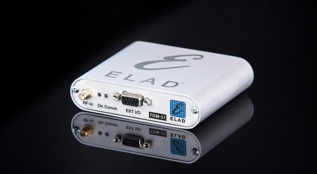
4 FDM-S1 Direct sampling SDR Receiver MHz font end Bandwidth Small size and weight x 27 x 88 mm g Powered by USB connection - Low power consumption < 2.2 W
5 FDM-S1

6 FDM-S1 L FDM-S1 is provided with proprietary software ELAD FDM-SW1
7 FDM-S1 Tunable frequencies: Receiver Mode: 0 30 MHz (Direct Sampling) Sampler Mode: MHz (Undersampling)
8 FDM-S1
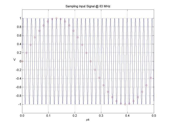
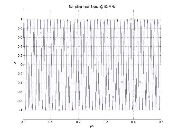
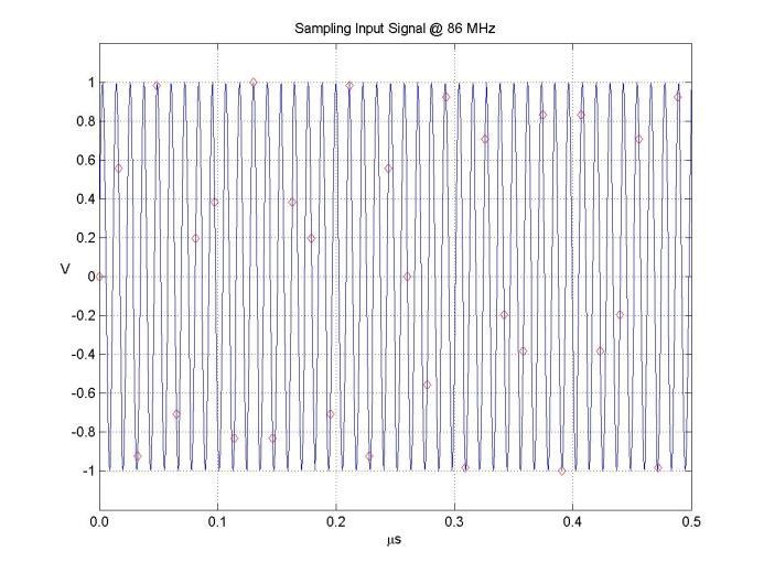
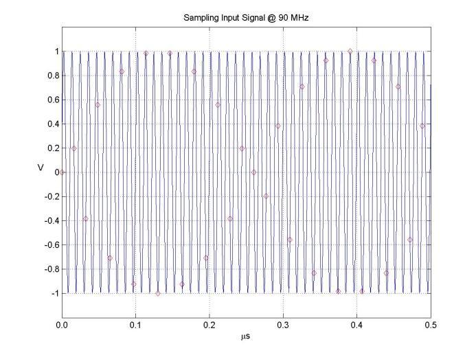
9 Sampling, Aliasing and Undersampling
10 Sampling theorem The sampling theorem states that if a signal s(t) contains no frequencies higher than B S(f)=0 per f>b f c 2B then it can be reconstructed exactly when it is sampled at a rate that is at least twice the maximum frequency component B. The frequency f N = f C /2 is called Nyquist frequency
11 Sampling theorem Example: FDM-S1 f c = MHz f n = B max = f c /2 = MHz According to the sampling theorem, we are able to analyze signals that contain frequency components up to 30 MHz
12 Sampling theorem
13 What happens when we don t comply with the sampling theorem? ALIASING
14 Aliasing In the presence of Aliasing, given a sampled signal s c (nt c ) (where T c =1/f c corresponds to the sampling interval), we are not able to know univocally the original signal s(t) Every frequency component of the original signal that has frequency greater than f N will be confused as a spectral component at frequency 0 f f N
15 Aliasing
16 Aliasing Due to the aliasing, in the 0 f f N frequency range we will have the superposition of each frequency that falls within the bandwidth of the analog-to-digital converter FDM-S1 front-end exhibits 200 MHz input bandwidth

17 Aliasing Aliasing
18 Aliasing Example: aliasing caused by FM broadcasting (89 MHz)
19 Aliasing Aliasing frequencies computation

20 Aliasing FDM-SW1 helps users highlighting frequencies that are multiples of the Nyquist frequency
21 Aliasing Be careful to correctly understand the signals that I obtain in the presence of aliasing
22 How can we avoid aliasing errors? Anti-Aliasing Filter
23 Anti-Aliasing Filter Filter which limits the bandwidth of the input signals cutting all the spectral components greater than the Nyquist frequency

24 Anti-Aliasing Filter


25 Anti-Aliasing Filter FDM-S1 has 30 MHz anti-aliasing filter
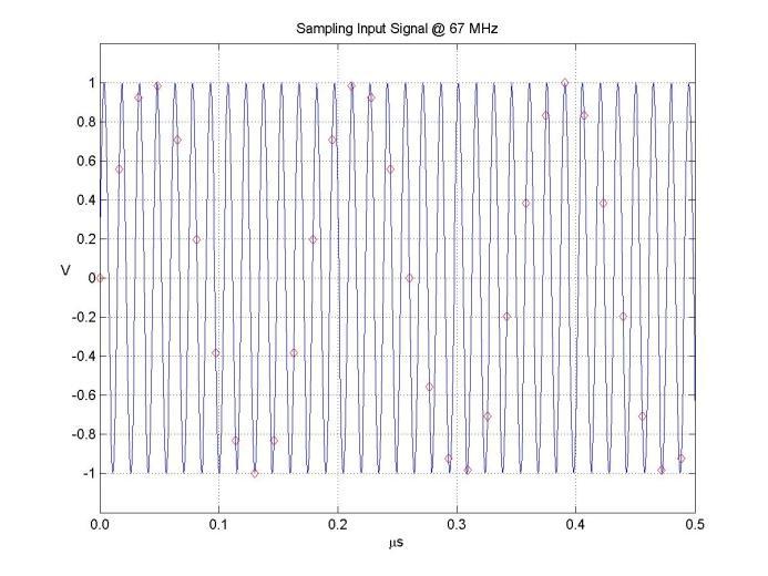
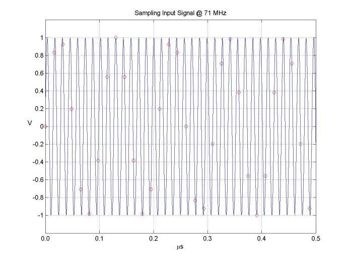
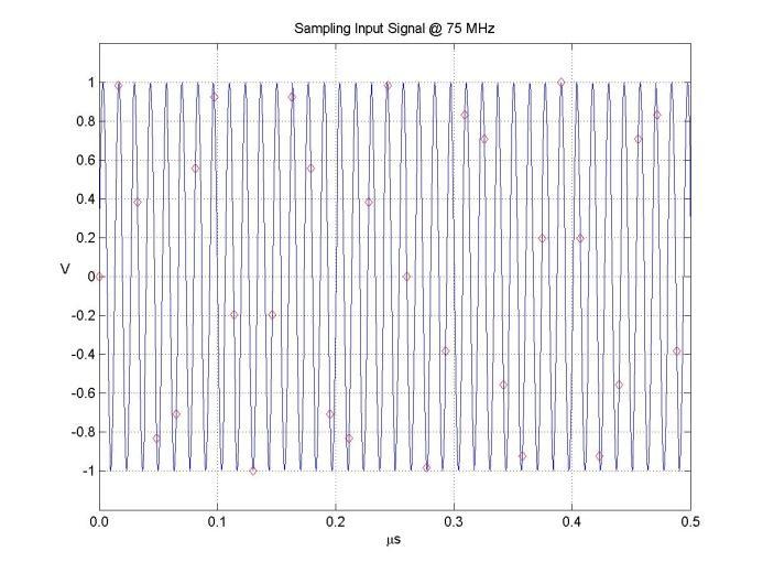
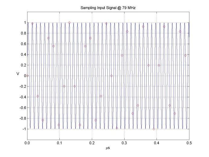
26 Is Aliasing always a bad issue? NO!!! We can take advantage of it UNDERSAMPLING
27 Undersampling Undersampling technique uses the Aliasing phenomenon to realize a digital mixer Undersampling is commonly implemented in several types of digital receiver, e.g. mobile phones Using undersampling technique, we are able to convert within the analysis band (0 f f N ) portions of the spectrum that are located at higher frequencies
28 Undersampling To avoid the superposition we must use preselection filters (band pass)

29 Undersampling

30 Undersampling with Preselector
31 Undersampling N.B.: preselection filter s bandwidth must satisfy the following rule N*f N B (N+1)*f N otherwise we will obtain aliasing again Example: filter for the FM MHz band
32 Undersampling No problem with the MHz band
33 Undersampling Elad will commercialize a partially mounted developing board (controlled by SW) to help users to develop custom preselection filters
34 FDM-SW1 Features
35 FDM-SW1 Features Innovative multi-level tuning bars - Fast tuning on the whole spectrum - Configurable span for Middle e Band bars - Patent Pending
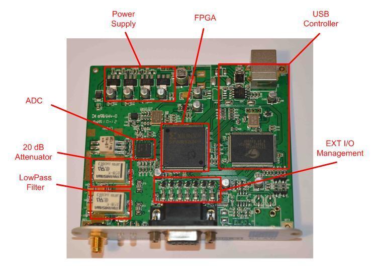
36 20 db attenuator FDM-SW1 Features Anti-aliasing filter (30 MHz Low-Pass)
 -")
37 FDM-SW1 Features Demodulation modes: - CW, CW SH+, CW SH-, USB, LSB, DSB - AM, SAM,FM, WB FM (Stereo + RDS) - DRM

38 FDM-SW1 Features Two Notch filters at IF stage
39 FDM-SW1 Features Adaptive De-Noiser (Audio) Adaptive Auto-Notch (Audio) Automatic Gain Control (Audio) - Slow, Medium, Fast and Manual

40 FDM-SW1 Features Advanced file recording/playback: - Fast file positioning using scrolling bar - Programmable recording - Settings memorization in the file s header
 EIBI database support Memories visualization on")
41 FDM-SW1 Features User station memory (file.xml) EIBI database support Memories visualization on the spectrum


42 FDM-SW1 Features 3 types of memories visualization

43 FDM-SW1 Features DX-Cluster connection and visualization of the connected users on the spectrum 3 types of visualization (same ways as memories)

44 FDM-SW1 Features Panadapter function - Configurable IF freq. and amplitude offset - Spectrum flip - CAT protocol (SW master or slave)
45 FDM-SW1 Features Possibility of using different USB sample rate (192, 384, 768, 1536 e 3072 khz, canali I/Q, 32 bit/sample) Possibility of using two soundcards Configurable presets - Frequency Step - Filter Bandwidth Possibility of using configurable default settings (mode, bandwidth, Att, LP30, etc) within user-defined frequency ranges Tmate and Tmate2 interface - Configurable function buttons

46 FDM-SW1 Features Apple virtual machine compatible (tested on VMware Fusion environment)
47 FDM-S1 Alternative Software


48 Alternative Software Thanks to a dll interface, FDM-S1 can be used with third party software
49 FDM-S1 Homebrew Radio Support

50 Homebrew Radio Support Users could improve the performances of FDM-S1 realizing custom filters on a developing board controlled by software (FDM-SW1 or third party)
51 SFE 1.0 board Homebrew Radio Support -DB9 interface between FDM-S1 and SFE board - 2 antenna input (SMA) - Possibility of switching 7 relays - 7 Led monitor for the 7 External I/O - 2 Led monitor for 5V from FDM-S1 and 12V Ext - Possibility of switching 1 bypass relay
52 Homebrew Radio Support SFE 1.0 schematic

53 Homebrew Radio Support SFE 1.0 setting using FDM-SW1

54 Homebrew Radio Support SFE 1.0 setting using third party software
55 ELAD Sales Network Sales of FDM-S1 are assigned only to EQP (Elad Qualified Partner) Woodbox Radio is EQP for Europe For professional uses and customizations, please contact directly ELAD company
56 Thanks Elad Team
sodirasdr Software-Radio Specification
 sodirasdr Software-Radio Specification Version of this document and SoDiRa software: 0.100 preview Table of contents Common Informations...3 Supported receiver...4 Internal direct supported receiver:...4
Technical Data. VXI HF Receiver WJ-8721 WATKINS-JOHNSON. Features
 May 1996 Technical Data WATKINS-JOHNSON VXI HF Receiver WJ-8721 The WJ-8721 is a fully synthesized, general-purpose HF receiver for surveillance, monitoring and direction finding for RF communi-cations
S.E. (Electronics/Electronics and Telecommunication Engg.) (Second Semester) EXAMINATION, 2014 COMMUNICATION THEORY (2008 PATTERN)
 (Second Semester) EXAMINATION, 2014 COMMUNICATION THEORY (2008 PATTERN)") Total No. of Questions 12] [Total No. of Printed Pages 7 Seat No. [4657]-49 S.E. (Electronics/Electronics and Telecommunication Engg.) (Second Semester) EXAMINATION, 2014 COMMUNICATION THEORY (2008 PATTERN)
Total No. of Questions 12] [Total No. of Printed Pages 7 Seat No. [4657]-49 S.E. (Electronics/Electronics and Telecommunication Engg.) (Second Semester) EXAMINATION, 2014 COMMUNICATION THEORY (2008 PATTERN)
ANALOG COMMUNICATION
 ANALOG COMMUNICATION TRAINING LAB Analog Communication Training Lab consists of six kits, one each for Modulation (ACL-01), Demodulation (ACL-02), Modulation (ACL-03), Demodulation (ACL-04), Noise power
PXA Configuration. Frequency range
 Keysight Technologies Making Wideband Measurements Using the Keysight PXA Signal Analyzer as a Down Converter with Infiniium Oscilloscopes and 89600 VSA Software Application Note Introduction Many applications
Technician License Course Chapter 2. Lesson Plan Module 3 Modulation and Bandwidth
 Technician License Course Chapter 2 Lesson Plan Module 3 Modulation and Bandwidth The Basic Radio Station What Happens During Radio Communication? Transmitting (sending a signal): Information (voice, data,
SIR-4011 MICROWAVE WIDEBAND DSP RECEIVER. WIDE FREQUENCY RANGE: GHz
 SIR-4011 MICROWAVE WIDEBAND DSP RECEIVER WIDE FREQUENCY RANGE: 0.5 18.0 GHz FEATURES Advanced Front Panel Graphics Display High Dynamic Range: In band Input IP3 > 0 dbm, NF< 15 db DSP Based AM, FM Video
A New Look at SDR Testing
 A New Look at SDR Testing (presented at SDR Academy 2016, Friedrichshafen, Germany) Adam Farson VA7OJ/AB4OJ Copyright 2016 A. Farson VA7OJ/AB4OJ 25-Dec-17 SDR Academy 2016 - SDR Testing 1 Performance issues
SoDiRa Software-Radio Specification
 SoDiRa Software-Radio Specification Version of this document and SoDiRa software: 0.100 preview Table of contents Common Informations...3 Supported receiver...4 Internal direct supported receiver:...4
Technical Data. Digital VXI VHF/UHF Receiver WJ-8629 WATKINS-JOHNSON
 Technical Data WATKINS-JOHNSON January 1997 Digital VXI VHF/UHF Receiver WJ-8629 The WJ-8629 is a general-purpose VHF/UHF receiver covering a 20 to 2700 MHz frequency range that utilizes Digital Signal
WiNRADiO. Scandinavia. G3 HF RECEIVERS. G313 e/i G31DDC Excalibur G33DDC Excalibur Pro G35DDC Excalibur Ultra
 WiNRADiO Scandinavia G3 HF RECEIVERS G313 e/i G31DDC Excalibur G33DDC Excalibur Pro G35DDC Excalibur Ultra 9 khz - 30 MHz (180 MHz) 9 khz - 49,995 MHz 9 khz - 49,995 MHz 1 khz - 45 MHz Malmö - Sweden Phone
Technical Data. Digital HF Receiver WJ-8712A WATKINS-JOHNSON. Features
 May 1996 Technical Data WATKINS-JOHNSON Digital HF Receiver WJ-8712A The WJ-8712A is a fully synthesized, general-purpose HF receiver for surveillance and monitoring of RF communications from 5 khz to
The Icom IC Adam Farson VA7OJ. A New Top-class HF/6m Transceiver. IC-7700 Information & Links
 The Icom IC-7700 A New Top-class HF/6m Transceiver Adam Farson VA7OJ IC-7700 Information & Links Copyright 2008 North Shore Amateur Radio Club NSARC HF Operators IC-7700 1 IC-7700 front panel This is a
TRANSCOM Manufacturing & Education
 www.transcomwireless.com 1 G6 Vector Signal Generator Overview G6 Vector Signal Generator is a high performance vector signal generator. It can generate arbitrary wave signal, continuous wave signal, common
PRODUCTS BROCHURE PRODUCTS OVERVIEW
 PRODUCTS BROCHURE WELCOME TO MOUNTAIN RF Mountain RF Sensors is engaged in the design and manufacture of specialty radio frequency (RF) products for government and military customers. The company is geared
ENSC327 Communications Systems 14: Multiplexing. School of Engineering Science Simon Fraser University
 ENSC327 Communications Systems 14: Multiplexing School of Engineering Science Simon Fraser University 1 Outline Required background (Recall various modulation schemes) Different Multiplexing strategies:
TitanSDR Receiver. User Manual v.1.9e
 TitanSDR Receiver User Manual v.1.9e Enablia S.r.l. (Italy) 2012 Before using the receiver, read carefully the Installation Manual and the User Manual. The symbol of the crossed out wheelie bin indicates
Technical Data. Compact Digital HF Receiver WJ-8710A WATKINS-JOHNSON. Features
 May 1996 Technical Data WATKINS-JOHNSON Compact Digital HF Receiver WJ-8710A The WJ-8710A is a fully synthesized, general-purpose HF receiver for surveillance and monitoring of RF communications from 5
WORLD BAND RADIO. AM/FM/SW/L W/AIR Band /SSB radio with LCD backlight OWNER S MANUAL
 WORLD BAND RADIO AM/FM/SW/L W/AIR Band /SSB radio with LCD backlight display and keypad direct entry OWNER S MANUAL WARNING Do not expose this appliance to rain or moisture Do not submerge or expose to
For the system to have the high accuracy needed for many measurements,
 Sampling and Digitizing Most real life signals are continuous analog voltages. These voltages might be from an electronic circuit or could be the output of a transducer and be proportional to current,
About the HDSDR software operations for the IC-R8600
 About the HDSDR software operations for the IC-R8600 These instructions describe how to use the HDSDR software. Before reading this guide, please read How to use the IC-R8600 as an SDR receiver that can
Using a Software Defined Radio As a Panadapter
 Using a Software Defined Radio As a Panadapter by Dave Core, K8WDA Presented to the Northern Kentucky Amateur Radio Club by Dave Core, K8WDA, on Oct. 9, 2017. What Is a Panadapter? Panadapter aka: Panoramic
Ascent Ground and Satellite Demonstration
 Ascent Ground and Satellite Demonstration By Ray Roberge, WA1CYB & Howie DeFelice, AB2S WA1CYB s1 Big Picture Goals Place more capable satellites into higher orbits Utilize software defined radios A programmable
Electronics A/D and D/A converters
 Electronics A/D and D/A converters Prof. Márta Rencz, Gábor Takács, Dr. György Bognár, Dr. Péter G. Szabó BME DED December 1, 2014 1 / 26 Introduction The world is analog, signal processing nowadays is
VHF/UHF Wideband ViXIceptor WJ-8621
 Developmental Specification WATKINS-JOHNSON May 1997 VHF/UHF Wideband ViXIceptor WJ-8621 The WJ-8621 is a general-purpose VHF/UHF receiver covering a 20 to 2700 MHz frequency range. WJ packages the unit
Sampling. A Simple Technique to Visualize Sampling. Nyquist s Theorem and Sampling
 Sampling Nyquist s Theorem and Sampling A Simple Technique to Visualize Sampling Before we look at SDR and its various implementations in embedded systems, we ll review a theorem fundamental to sampled
GAO-SAU-105 Spectrum Analyzer with Wide Frequency Range
 GAO-SAU-105 Spectrum Analyzer with Wide Frequency Range GAOTek Spectrum Analyzer with Wide Frequency Range has excellent performance to test dynamic range, phase noise, amplitude accuracy and test speed.
High Dynamic Range Receiver Parameters
 High Dynamic Range Receiver Parameters The concept of a high-dynamic-range receiver implies more than an ability to detect, with low distortion, desired signals differing, in amplitude by as much as 90
Keysight Technologies N9320B RF Spectrum Analyzer
 Keysight Technologies N9320B RF Spectrum Analyzer 9 khz to 3.0 GHz Data Sheet Definitions and Conditions The spectrum analyzer will meet its specifications when: It is within its calibration cycle It has
Agilent N9320B RF Spectrum Analyzer
 Agilent N9320B RF Spectrum Analyzer 9 khz to 3.0 GHz Data Sheet Definitions and Conditions The spectrum analyzer will meet its specifications when: It is within its calibration cycle It has been turned
: Triple PLL, lowest reference frequency 10 khz. : ± 5 khz in 10 Hz steps, synthesized.
 PETER DE CONINCK HAGENUK RX 1001MVB RECEIVER ONL4234 SERIAL N 5820-310-6162 BELGIAN SWL DRAWING N 97 8 2.164 Technical data Frequency range Frequency resolution Frequency tuning Frequency synthesizer Frequency
NCR Channelizer Server
 NCR Channelizer Server Thousands of Signals One Receiver Novator Channelizer Receiver system lets you analyze thousands of signals with a single receiver. It streams channelized data to other systems where
Software defined radio transceiver (SDR) CW & RTTY Skimmer Server Weak Signal Propagation Reporter (WSPR)
 CW & RTTY Skimmer Server Weak Signal Propagation Reporter (WSPR)") Red Pitaya STEMlab solutions are an indispensable part of equipment in Ham Radio Operators lab. With a single click STEMlab can be transformed into several applications like: Software defined radio transceiver
Red Pitaya STEMlab solutions are an indispensable part of equipment in Ham Radio Operators lab. With a single click STEMlab can be transformed into several applications like: Software defined radio transceiver
Outline. Communications Engineering 1
 Outline Introduction Signal, random variable, random process and spectra Analog modulation Analog to digital conversion Digital transmission through baseband channels Signal space representation Optimal
SC5407A/SC5408A 100 khz to 6 GHz RF Upconverter. Datasheet. Rev SignalCore, Inc.
 SC5407A/SC5408A 100 khz to 6 GHz RF Upconverter Datasheet Rev 1.2 2017 SignalCore, Inc. support@signalcore.com P R O D U C T S P E C I F I C A T I O N S Definition of Terms The following terms are used
ELAD FDM-DUO Dual Mode SDR Transceiver USER MANUAL
 ELAD FDM-DUO Dual Mode SDR Transceiver USER MANUAL www.eladit.com Contents Revision History... 4 1 Overview... 5 1.1 Notice... 5 1.2 Firmware versions... 5 1.3 Introduction... 5 1.3.1 Main Features...
A DSP IMPLEMENTED DIGITAL FM MULTIPLEXING SYSTEM
 A DSP IMPLEMENTED DIGITAL FM MULTIPLEXING SYSTEM Item Type text; Proceedings Authors Rosenthal, Glenn K. Publisher International Foundation for Telemetering Journal International Telemetering Conference
HS9000 SERIES. RoHS. Multi-Channel RF Synthesizers
 Holzworth has refined its multi-channel platform in the form of the HS9000 Series for integration of the HSM Series Single Channel Synthesizers. The HS9000 series is designed to achieve optimal channel-to-channel
An Introduction to Software Defined Radio. What is it? Why do I want one? How do I choose one?
 An Introduction to Software Defined Radio What is it? Why do I want one? How do I choose one? What is an SDR? A radio communication system where many components that have been traditionally implemented
Problems from the 3 rd edition
 (2.1-1) Find the energies of the signals: a) sin t, 0 t π b) sin t, 0 t π c) 2 sin t, 0 t π d) sin (t-2π), 2π t 4π Problems from the 3 rd edition Comment on the effect on energy of sign change, time shifting
Design Implementation Description for the Digital Frequency Oscillator
 Appendix A Design Implementation Description for the Frequency Oscillator A.1 Input Front End The input data front end accepts either analog single ended or differential inputs (figure A-1). The input
DSA-815 Demo Guide. Solution: The DSA 800 series of spectrum analyzers are packed with features.
 FAQ Instrument Solution FAQ Solution Title DSA-815 Demo Guide Date:08.29.2012 Solution: The DSA 800 series of spectrum analyzers are packed with features. Spectrum analyzers are similar to oscilloscopes..
AM and FM MODULATION Lecture 5&6
 AM and FM MODULATION Lecture 5&6 Ir. Muhamad Asvial, MEng., PhD Center for Information and Communication Engineering Research Electrical Engineering Department University of Indonesia Kampus UI Depok,
OBJECTIVES EQUIPMENT LIST
 1 Reception of Amplitude Modulated Signals AM Demodulation OBJECTIVES The purpose of this experiment is to show how the amplitude-modulated signals are demodulated to obtain the original signal. Also,
RF Tuning Range. Intermediate Frequencies. The RF tuning range of the SDRplay module is detailed below.
 The SDR-play RSP1 is a powerful wideband full-featured SDR which coers all frequencies from 1 khz up to 2 GHz. All it needs is a PC and an antenna to proide excellent communications receier functionality.
FYS3240 PC-based instrumentation and microcontrollers. Signal sampling. Spring 2017 Lecture #5
 FYS3240 PC-based instrumentation and microcontrollers Signal sampling Spring 2017 Lecture #5 Bekkeng, 30.01.2017 Content Aliasing Sampling Analog to Digital Conversion (ADC) Filtering Oversampling Triggering
Software Defined Radio! Primer + Project! Gordie Neff, N9FF! Columbia Amateur Radio Club! March 2016!
 Software Defined Radio! Primer + Project! Gordie Neff, N9FF! Columbia Amateur Radio Club! March 2016! Overview! What is SDR?! Why should I care?! SDR Concepts! Potential SDR project! 2! Approach:! This
PXIe Contents SPECIFICATIONS. 14 GHz and 26.5 GHz Vector Signal Analyzer
 SPECIFICATIONS PXIe-5668 14 GHz and 26.5 GHz Vector Signal Analyzer These specifications apply to the PXIe-5668 (14 GHz) Vector Signal Analyzer and the PXIe-5668 (26.5 GHz) Vector Signal Analyzer with
3.2 Measuring Frequency Response Of Low-Pass Filter :
 2.5 Filter Band-Width : In ideal Band-Pass Filters, the band-width is the frequency range in Hz where the magnitude response is at is maximum (or the attenuation is at its minimum) and constant and equal
Appendix B. Design Implementation Description For The Digital Frequency Demodulator
 Appendix B Design Implementation Description For The Digital Frequency Demodulator The DFD design implementation is divided into four sections: 1. Analog front end to signal condition and digitize the
Preliminary features of the SDR-X receiver SDR-X , PowerSDR Winrad Winrad DDS SFDR SFDR AD995 AD99 1
 Preliminary features of the SDR-X receiver The SDR-X receiver, in its full version is capable of continuously tuning the entire HF spectrum, 6m ( 50-52 MHz) band included. SSB, AM etc. demodulation, bandpass
JUMA-TRX2 DDS / Control Board description OH2NLT
 JUMA-TRX2 DDS / Control Board description OH2NLT 22.08.2007 General Key functions of the JUMA-TRX2 DDS / Control board are: - provide user interface functions with LCD display, buttons, potentiometers
LnR Precision, Inc. 107 East Central Avenue, Asheboro, NC
 LD5 CW/SSB QRP Transceiver Quick guide manual Description: At the development base of the digital signal processing unit, an algorithm is embedded for IQ processing of the channels with phase suppression
Digital HF Receiver WJ-8723
 Developmental Specification WATKINS-JOHNSON April 1996 Digital HF Receiver WJ-8723 Description The WJ-8723 is a fully synthesized, general-purpose HF receiver that monitors RF communications from 5 khz
Spectrum Analyzers: Sweep and Bandwidth Considerations
 1 ELEC 391 - Electrical Engineering Design Studio II Spectrum Analyzers: Sweep and Bandwidth Considerations Introduction to project management. Problem definition. Design principles and practices. Implementation
Music 270a: Fundamentals of Digital Audio and Discrete-Time Signals
 Music 270a: Fundamentals of Digital Audio and Discrete-Time Signals Tamara Smyth, trsmyth@ucsd.edu Department of Music, University of California, San Diego October 3, 2016 1 Continuous vs. Discrete signals
Lecture 6. Angle Modulation and Demodulation
 Lecture 6 and Demodulation Agenda Introduction to and Demodulation Frequency and Phase Modulation Angle Demodulation FM Applications Introduction The other two parameters (frequency and phase) of the carrier
RSP family of Full Featured Wideband SDR Receivers
 RSP family of Full Featured Wideband SDRuno SDR receivers What is an SDR? A radio communication system where components that have been traditionally implemented in hardware (e.g. mixers, filters, amplifiers,
Figure 1: Block diagram of Digital signal processing
 Experiment 3. Digital Process of Continuous Time Signal. Introduction Discrete time signal processing algorithms are being used to process naturally occurring analog signals (like speech, music and images).
Amplitude Modulated Systems
 Amplitude Modulated Systems Communication is process of establishing connection between two points for information exchange. Channel refers to medium through which message travels e.g. wires, links, or
Exercise 1: RF Stage, Mixer, and IF Filter
 SSB Reception Analog Communications Exercise 1: RF Stage, Mixer, and IF Filter EXERCISE OBJECTIVE DISCUSSION On the circuit board, you will set up the SSB transmitter to transmit a 1000 khz SSB signal
Digital Processing of Continuous-Time Signals
 Chapter 4 Digital Processing of Continuous-Time Signals 清大電機系林嘉文 cwlin@ee.nthu.edu.tw 03-5731152 Original PowerPoint slides prepared by S. K. Mitra 4-1-1 Digital Processing of Continuous-Time Signals Digital
TE 302 DISCRETE SIGNALS AND SYSTEMS. Chapter 1: INTRODUCTION
 TE 302 DISCRETE SIGNALS AND SYSTEMS Study on the behavior and processing of information bearing functions as they are currently used in human communication and the systems involved. Chapter 1: INTRODUCTION
Federal Communications Commission Office of Engineering and Technology Laboratory Division
 April 9, 2013 Federal Communications Commission Office of Engineering and Technology Laboratory Division Guidance for Performing Compliance Measurements on Digital Transmission Systems (DTS) Operating
Keysight X-Series Signal Analyzer
 Keysight X-Series Signal Analyzer This manual provides documentation for the following Analyzers: N9040B UXA N9030B PXA N9020B MXA N9010B EXA N9000B CXA N9063C Analog Demod Measurement Application Measurement
System on a Chip. Prof. Dr. Michael Kraft
 System on a Chip Prof. Dr. Michael Kraft Lecture 5: Data Conversion ADC Background/Theory Examples Background Physical systems are typically analogue To apply digital signal processing, the analogue signal
FMR MHz Receiver with Two Relay Outputs
 FMR-202 27MHz Receiver with Two Relay Features Crystal Controlled 2-Channel Digitally Encoded Applications Remote control of garage doors, gates, lights, alarms Description The FMR-202 is a crystal controlled
Technical Data. Digital HF Receiver HF-1000A WATKINS-JOHNSON. Features
 Technical Data November 1996 WATKINS-JOHNSON Digital HF Receiver HF-1000A The HF-1000A is a fully synthesized, general-purpose HF receiver that monitors RF communications from 5 khz to 30 MHz with 1-Hz
Demo / Application Guide for DSA815(-TG) / DSA1000 Series
 / DSA1000 Series") Demo / Application Guide for DSA815(-TG) / DSA1000 Series TX1000 Mobile Phone Frontend Mixer Bandpass Filter PA The schematic above shows a typical front end of a mobile phone. Our TX1000 RF Demo Kit shows
Demo / Application Guide for DSA815(-TG) / DSA1000 Series TX1000 Mobile Phone Frontend Mixer Bandpass Filter PA The schematic above shows a typical front end of a mobile phone. Our TX1000 RF Demo Kit shows
Digital Processing of
 Chapter 4 Digital Processing of Continuous-Time Signals 清大電機系林嘉文 cwlin@ee.nthu.edu.tw 03-5731152 Original PowerPoint slides prepared by S. K. Mitra 4-1-1 Digital Processing of Continuous-Time Signals Digital
Spectrum Analyzers R3132/3132N/3162 R3132/3132N/3162. Low cost, high performance. General-Purpose Spectrum Analyzer Adaptable to Various Applications
 Frequency band R3132 9 khz to 3 GHz R3132N:9 khz to 3 GHz R3162: 9 khz to 8 GHz High signal purity: -105 dbc (20 khz offset) Total level accuracy: ±1.5 db High speed GPIB useful for high speed productions
IC-R8500 Test Report. By Adam Farson VA7OJ/AB4OJ
 IC-R8500 Test Report By Adam Farson VA7OJ/AB4OJ Iss. 1, Dec. 14, 2015. Figure 1: The Icom IC-R8500. Introduction: This report presents results of an RF lab test suite performed on the IC- R8500 receiver.
LNS ultra low phase noise Synthesizer 8 MHz to 18 GHz
 LNS ultra low phase noise Synthesizer 8 MHz to 18 GHz Datasheet The LNS is an easy to use 18 GHz synthesizer that exhibits outstanding phase noise and jitter performance in a 3U rack mountable chassis.
Using High Speed Differential Amplifiers to Drive Analog to Digital Converters
 Using High Speed Differential Amplifiers to Drive Analog to Digital Converters Selecting The Best Differential Amplifier To Drive An Analog To Digital Converter The right high speed differential amplifier
Utilizzo del Time Domain per misure EMI
 Utilizzo del Time Domain per misure EMI Roberto Sacchi Measurement Expert Manager - Europe 7 Giugno 2017 Compliance EMI receiver requirements (CISPR 16-1-1 ) range 9 khz - 18 GHz: A normal +/- 2 db absolute
HF Receivers, Part 3
 HF Receivers, Part 3 Introduction to frequency synthesis; ancillary receiver functions Adam Farson VA7OJ View an excellent tutorial on receivers Another link to receiver principles NSARC HF Operators HF
ECE 6560 Multirate Signal Processing Chapter 13
 Multirate Signal Processing Chapter 13 Dr. Bradley J. Bazuin Western Michigan University College of Engineering and Applied Sciences Department of Electrical and Computer Engineering 1903 W. Michigan Ave.
D-808. FM Stereo/LW/MW/SW-SSB AIR RDS Synthesized Receiver
 XHDATA D-808 FM Stereo/LW/MW/SW-SSB AIR RDS Synthesized Receiver WARNING Do not expose this appliance to rain or moisture Do not submerge or expose to water Protect from high humidity and rain Only operate
Software Defined Radios
 Software Defined Radios What Is the SDR Radio? An SDR in general is a radio that has: Primary Functionality [modulation and demodulation, filtering, etc.] defined in software. DSP algorithms implemented
S.R.M. Institute of Science & Technology School of Electronics & Communication Engineering
 S.R.M. Institute of Science & Technology School of Electronics & Communication Engineering QUESTION BANK Subject Code : EC314 Subject Name : Communication Engineering Year & Sem : III Year, 6th Sem (EEE)
DSA700 Series Spectrum Analyzer
 DSA700 Series Spectrum Analyzer Product Features: All-Digital IF Technology Frequency Range from 100 khz up to 1 GHz Min. -155 dbm Displayed Average Noise Level (Typ.) Min.
TECSUN PL-365. FM stereo / MW / SW-SSB DSP RECEIVER OPERATION MANUAL ELECTRONIC IND. LTD. RADIOS AUSTRALIA
 TECSUN TECSUN RADIOS AUSTRALIA PL-365 FM stereo / MW / SW-SSB DSP RECEIVER OPERATION MANUAL TECSUN PL-365 FM STEREO/MW/SW-SSB DSP RECEIVER TECSUN RADIOS TECSUN AUSTRALIA ELECTRONIC IND. LTD. PL-365 Functional
EE390 Final Exam Fall Term 2002 Friday, December 13, 2002
 Name Page 1 of 11 EE390 Final Exam Fall Term 2002 Friday, December 13, 2002 Notes 1. This is a 2 hour exam, starting at 9:00 am and ending at 11:00 am. The exam is worth a total of 50 marks, broken down
Radio Frequency Design to Support Software Transceiver for Wireless Communications
 Radio Frequency Design to Support Software Transceiver for Wireless Communications Author: Cazzie Williams Western Michigan University Whirlpool Corporation Advisor/Sponsor: Dr. Frank Severance and Dr.
S.R.M Institute of Science and Technology (Deemed University) Department of Electronics & Communication Engineering
 Department of Electronics & Communication Engineering") S.R.M Institute of Science and Technology (Deemed University) Department of Electronics & Communication Engineering QUESTION BANK Subject Code : EC211 Subject Name : Communication Engineering Year & Sem
S.R.M Institute of Science and Technology (Deemed University) Department of Electronics & Communication Engineering QUESTION BANK Subject Code : EC211 Subject Name : Communication Engineering Year & Sem
Based with permission on lectures by John Getty Laboratory Electronics II (PHSX262) Spring 2011 Lecture 9 Page 1
 Spring 2011 Lecture 9 Page 1") Today 3// Lecture 9 Analog Digital Conversion Sampled Data Acquisition Systems Discrete Sampling and Nyquist Digital to Analog Conversion Analog to Digital Conversion Homework Study for Exam next week
Today 3// Lecture 9 Analog Digital Conversion Sampled Data Acquisition Systems Discrete Sampling and Nyquist Digital to Analog Conversion Analog to Digital Conversion Homework Study for Exam next week
(Translated with Google Translate. Sorry, probably not the best English )
") 1 Flashing Firmware The.hex file (in the download) may be flashed e.g. with BASCOM, AVR Studio (ATMEL Studio) or myarv Prog Tool via ISP. Details can be found here: http://dl6gl.de/software/avr-programmieren-mit-bascom-und-avr-studio
1 Flashing Firmware The.hex file (in the download) may be flashed e.g. with BASCOM, AVR Studio (ATMEL Studio) or myarv Prog Tool via ISP. Details can be found here: http://dl6gl.de/software/avr-programmieren-mit-bascom-und-avr-studio
The Discussion of this exercise covers the following points: Filtering Aperture distortion
 Exercise 3-1 PAM Signals Demodulation EXERCISE OBJECTIVE When you have completed this exercise you will be able to demonstrate the recovery of the original message signal from a PAM signal using the PAM
SAMPLING FREQUENCY SELECTION SCHEME FOR A MULTIPLE SIGNAL RECEIVER USING UNDERSAMPLING
 SAMPLING FREQUENCY SELECTION SCHEME FOR A MULTIPLE SIGNAL RECEIVER USING UNDERSAMPLING Yoshio Kunisawa (KDDI R&D Laboratories, yokosuka, kanagawa, JAPAN; kuni@kddilabs.jp) ABSTRACT A multi-mode terminal
BASEBAND SIGNAL PROCESSING FM BROADCAST SIGNAL ECE 3101
 BASEBAND SIGNAL PROCESSING FM BROADCAST SIGNAL ECE 3101 FM PRE-EMPHASIS 1. In FM, the noise increases with increasing modulation frequency. 2. To compensate for this effect, FM communication systems incorporate
ENSC327 Communications Systems 14: Multiplexing. Jie Liang School of Engineering Science Simon Fraser University
 ENSC327 Communications Systems 14: Multiplexing Jie Liang School of Engineering Science Simon Fraser University 1 Outline Multiplexing allows signals to share channels Many different strategies are possible
Analog signal generator that meets virtually every requirement
 GENERAL PURPOSE 44434/5 FIG 1 The R&S SMA1A offers excellent performance and compact design at a favorable price. Signal Generator R&S SMA1A Analog signal generator that meets virtually every requirement
The Fundamentals of Mixed Signal Testing
 The Fundamentals of Mixed Signal Testing Course Information The Fundamentals of Mixed Signal Testing course is designed to provide the foundation of knowledge that is required for testing modern mixed
Swept-tuned spectrum analyzer. Gianfranco Miele, Ph.D
 Swept-tuned spectrum analyzer Gianfranco Miele, Ph.D www.eng.docente.unicas.it/gianfranco_miele g.miele@unicas.it Reference level and logarithmic amplifier The signal displayed on the instrument screen
UNIT-I AMPLITUDE MODULATION (2 Marks Questions and Answers)
") UNIT-I AMPLITUDE MODULATION (2 Marks Questions and Answers) 1. Define modulation? Modulation is a process by which some characteristics of high frequency carrier Signal is varied in accordance with the
UNIT-I AMPLITUDE MODULATION (2 Marks Questions and Answers) 1. Define modulation? Modulation is a process by which some characteristics of high frequency carrier Signal is varied in accordance with the
PN9000 PULSED CARRIER MEASUREMENTS
 The specialist of Phase noise Measurements PN9000 PULSED CARRIER MEASUREMENTS Carrier frequency: 2.7 GHz - PRF: 5 khz Duty cycle: 1% Page 1 / 12 Introduction When measuring a pulse modulated signal the
Expert Electronics ColibriNANO SDR Receiver
 Mark J. Wilson, K1RO, k1ro@arrl.org Product Review Expert Electronics ColibriNANO SDR Receiver Reviewed by Pascal Villeneuve, VA2PV va2pv@arrl.net In recent years, software-defined radio (SDR) technology
AM Limitations. Amplitude Modulation II. DSB-SC Modulation. AM Modifications
 Lecture 6: Amplitude Modulation II EE 3770: Communication Systems AM Limitations AM Limitations DSB-SC Modulation SSB Modulation VSB Modulation Lecture 6 Amplitude Modulation II Amplitude modulation is
!"!#"#$% Lecture 2: Media Creation. Some materials taken from Prof. Yao Wang s slides RECAP
 Lecture 2: Media Creation Some materials taken from Prof. Yao Wang s slides RECAP #% A Big Umbrella Content Creation: produce the media, compress it to a format that is portable/ deliverable Distribution:
Triarchy VSG6G1C USB Vector RF Signal Generator Operating Manual
 Triarchy VSG6G1C USB Vector RF Signal Generator Operating Manual CW signal NB RF noise generator Analog modulation GMSK modulation Frequency sweeping Hopping with data Mod Page 1 of 27 8PSK GSM signal