MOBEXCOM P25 DIGITAL VE EHICULAR REPEATER APX Series Mobile Radios P25 Interface Installation & Programming Guide 8M083X25 R3
|
|
|
- Elisabeth Perry
- 6 years ago
- Views:
Transcription
1 MOBEXCOM P25 DIGITAL VEHICULAR REPEATER APX Series Mobile Radios P25 Interface Installation & Programming Guide 8M083X25 R3
2 NOTES 8M083X25 R3 ii
3 Related Publications Publication Number 8A083X30 8A083X20 8A083X21 8M083X02 8F083X03 8F083X14 8F083X15 8F083X16 8F083X04 Description DVRS User s Manual, APX Series Interface DVRS User s Manual, XTL2500 / XTL5000 Interface Tactical DVR User s Manual Tactical DVR Installation and Programming Guide DVRS - Product & RF Safety Booklet Indoor Fixed Mount DVRS Installation Guide, APX Interface Outdoor Fixed Mount DVRS Installation Guide, APX Interface Transportable DVRS Installation Guide, APX Interface Flash Loader and Tweaker Programmer Installation Guide Manual Revisions Rev # Date ECN tes & References 0 July na Original Release 1 August 7, Encryption restrictions update 2 vember 22, Firmware R1.01 / Tweaker 1.02 update 3 December 8, Firmware R1.10 Update 8M083X25 R3 iii
4 Foreword The P25 Digital Vehicular Repeater (DVR) is designed to be seamlessly interfaced to: Remote Mount XTL2500 or XTL5000 Digital Mobile Subscriber Unit (MSU) with M5, O3 or O5 Control Head Remote Mount APX Series MSU with or without control head This manual provides Installation and Programming guidelines for the Futurecom Mobexcom P25 DVR that is interfaced to the following remote mount APX Series Mobile radios: Mobile Radio Model Firmware Requirements tes APX2500 R or later Requires option GA00631 APX4500 R or later Requires option GA00631 APX5500 R or later Requires option GA00631 APX6500 R or later Requires option GA00631 APX7500 R or later Requires option GA00631 NOTE: Mobile Radio must be configured as Remote Mount in order to be compatible with the DVRS. For Installation and Programming guidelines of the XTL interfaced DVRS models, please refer to publication 8M083X01. When the DVR is interfaced to a Remote Mount Motorola Mobile Radio, the complete equipment package is referred to as Digital Vehicular Repeater System (DVRS). The DVR may also be used as a stand alone (Tactical) repeater. The operation of the Tactical DVR is described in publication 8A083X21. The Installation & Programming Guidelines referring to the Tactical DVR Model are described in document 8M083X02. For details on the DVRS Operation, please refer to the DVRS User s Guides 8A083X20 (XTL interface) or 8A083X30 (APX interface). For details on the APX TM 6500 or APX TM 7500 Mobile Radio operation, please refer to the applicable Manuals available from Motorola. 8M083X25 R3 iv
5 The DVRS Operation described in this Document requires the following Firmware: APX Series Mobile Radios - firmware release: Host R or later. APX Mobile Radio Control Head - firmware release R or later. APX Mobile Radios operating as the host mobile for the DVR require subscriber option GA00631 for operation. XTS1500 / XTS2500 / XTS firmware release R or later. APX2000 / APX4000 / APX6000 / APX7000 firmware release R or later. APX Portable Radios operating through a DVR, utilizing the enhanced DVR digital feature set require subscriber option QA DVR must be loaded with firmware release: Application 4C083X11 R01.10 or later. Tweaker Programming software 6A083X05 Version 1.04 or later. Computer Software Copyrights The products described in this manual include copyrighted Futurecom computer programs stored in semiconductor memories or other media. Laws in the United States, Canada and other countries preserve for Futurecom certain exclusive rights for copyrighted computer programs, including but not limited to, the exclusive right to copy or reproduce in any form the copyrighted computer programs. Any copyrighted computer program contained in the Futurecom products described in this manual may not be copied, reproduced, modified, reverse-engineered, or distributed in any manner without the express written permission of Futurecom. The purchase of Futurecom products shall not be deemed to grant either directly or by implication, estoppels, or otherwise, any license under the copyrights, patents or patent applications of Futurecom, except for the normal non-exclusive license to use that arises by operation of law in the sale of a product. 8M083X25 R3 v
6 The Tweaker Programming Software provided by Futurecom Systems Group ULC includes the following Publicly Available Software. Publicly Available Software List Name: MFC Grid Control Version: 2.24 Modified: Software Site: Source Code: Source Code Distribution Obligations. The Source Code may be obtained from the original Software Site. License: The Article associated with the Source Code is licensed under the Code Project Open License (CPOL), version Reference the Common Licenses Section for the terms of the CPOL. The Source Code licensed is under Custom Freeware / Open Source Software License, see below: Written by Chris Maunder <chris@codeproject.com> Copyright (c) All Rights Reserved. This code may be used in compiled form in any way you desire. This file may be redistributed unmodified by any means PROVIDING it is not sold for profit without the authors written consent, and providing that this notice and the authors name and all copyright notices remains intact. An letting me know how you are using it would be nice as well. This file is provided "as is" with no expressed or implied warranty. The author accepts no liability for any damage/loss of business that this product may cause. Additional tices: CInPlaceEdit, licensed under the CodeGuru License. Refer to the Common Licenses Section for the terms of the CodeGuru License. Credits: Zafir Anjum Eric Woodruff Ken Bertelson Joe Willcoxson 8M083X25 R3 vi
7 Publicly Available Software Common Licenses The Code Project Open License (CPOL) 1.02 Preamble This License governs Your use of the Work. This License is intended to allow developers to use the Source Code and Executable Files provided as part of the Work in any application in any form. The main points subject to the terms of the License are: Source Code and Executable Files can be used in commercial applications; Source Code and Executable Files can be redistributed; and Source Code can be modified to create derivative works. claim of suitability, guarantee, or any warranty whatsoever is provided. The software is provided "as-is". The Article accompanying the Work may not be distributed or republished without the Author's consent This License is entered between You, the individual or other entity reading or otherwise making use of the Work licensed pursuant to this License and the individual or other entity which offers the Work under the terms of this License ("Author"). License THE WORK (AS DEFINED BELOW) IS PROVIDED UNDER THE TERMS OF THIS CODE PROJECT OPEN LICENSE ("LICENSE"). THE WORK IS PROTECTED BY COPYRIGHT AND/OR OTHER APPLICABLE LAW. ANY USE OF THE WORK OTHER THAN AS AUTHORIZED UNDER THIS LICENSE OR COPYRIGHT LAW IS PROHIBITED. BY EXERCISING ANY RIGHTS TO THE WORK PROVIDED HEREIN, YOU ACCEPT AND AGREE TO BE BOUND BY THE TERMS OF THIS LICENSE. THE AUTHOR GRANTS YOU THE RIGHTS CONTAINED HEREIN IN CONSIDERATION OF YOUR ACCEPTANCE OF SUCH TERMS AND CONDITIONS. IF YOU DO NOT AGREE TO ACCEPT AND BE BOUND BY THE TERMS OF THIS LICENSE, YOU CANNOT MAKE ANY USE OF THE WORK. 1. Definitions. a. "Articles" means, collectively, all articles written by Author which describes how the Source Code and Executable Files for the Work may be used by a user. b. "Author" means the individual or entity that offers the Work under the terms of this License. c. "Derivative Work" means a work based upon the Work or upon the Work and other preexisting works. d. "Executable Files" refer to the executable files, binary files, configuration and any required data files included in the Work. e. "Publisher" means the provider of the website, magazine, CD-ROM, DVD or other medium from or by which the Work is obtained by You. f. "Source Code" refers to the collection of source code and configuration files used to create the Executable Files. g. "Standard Version" refers to such a Work if it has not been modified, or has been modified in accordance with the consent of the Author, such consent being in the full discretion of the Author. h. "Work" refers to the collection of files distributed by the Publisher, including the Source Code, Executable Files, binaries, data files, documentation, whitepapers and the Articles. i. "You" is you, an individual or entity wishing to use the Work and exercise your rights under this License. 8M083X25 R3 vii
8 2. Fair Use/Fair Use Rights. thing in this License is intended to reduce, limit, or restrict any rights arising from fair use, fair dealing, first sale or other limitations on the exclusive rights of the copyright owner under copyright law or other applicable laws. 3. License Grant. Subject to the terms and conditions of this License, the Author hereby grants You a worldwide, royalty-free, non-exclusive, perpetual (for the duration of the applicable copyright) license to exercise the rights in the Work as stated below: a. You may use the standard version of the Source Code or Executable Files in Your own applications. b. You may apply bug fixes, portability fixes and other modifications obtained from the Public Domain or from the Author. A Work modified in such a way shall still be considered the standard version and will be subject to this License. c. You may otherwise modify Your copy of this Work (excluding the Articles) in any way to create a Derivative Work, provided that You insert a prominent notice in each changed file stating how, when and where You changed that file. d. You may distribute the standard version of the Executable Files and Source Code or Derivative Work in aggregate with other (possibly commercial) programs as part of a larger (possibly commercial) software distribution. e. The Articles discussing the Work published in any form by the author may not be distributed or republished without the Author's consent. The author retains copyright to any such Articles. You may use the Executable Files and Source Code pursuant to this License but you may not repost or republish or otherwise distribute or make available the Articles, without the prior written consent of the Author. Any subroutines or modules supplied by You and linked into the Source Code or Executable Files of this Work shall not be considered part of this Work and will not be subject to the terms of this License. 4. Patent License. Subject to the terms and conditions of this License, each Author hereby grants to You a perpetual, worldwide, non-exclusive, no-charge, royalty-free, irrevocable (except as stated in this section) patent license to make, have made, use, import, and otherwise transfer the Work. 5. Restrictions. The license granted in Section 3 above is expressly made subject to and limited by the following restrictions: a. You agree not to remove any of the original copyright, patent, trademark, and attribution notices and associated disclaimers that may appear in the Source Code or Executable Files. b. You agree not to advertise or in any way imply that this Work is a product of Your own. c. The name of the Author may not be used to endorse or promote products derived from the Work without the prior written consent of the Author. d. You agree not to sell, lease, or rent any part of the Work. This does not restrict you from including the Work or any part of the Work inside a larger software distribution that itself is being sold. The Work by itself, though, cannot be sold, leased or rented. e. You may distribute the Executable Files and Source Code only under the terms of this License, and You must include a copy of, or the Uniform Resource Identifier for, this License with every copy of the Executable Files or Source Code You distribute and ensure that anyone receiving such Executable Files and Source Code agrees that the terms of this License apply to such Executable Files and/or Source Code. You may not offer or impose any terms on the Work that alter or restrict the terms of this License or the recipients' exercise of the rights granted hereunder. You may not sublicense the Work. You must keep intact all notices that refer to this License and to the disclaimer of warranties. You may not distribute the Executable Files or Source Code with any technological measures that control access or use of the Work in a manner inconsistent with the terms of this License. f. You agree not to use the Work for illegal, immoral or improper purposes, or on pages containing illegal, immoral or improper material. The Work is subject to applicable export laws. You agree to comply with all such laws and regulations that may apply to the Work after Your receipt of the Work. 6. Representations, Warranties and Disclaimer. THIS WORK IS PROVIDED "AS IS", "WHERE IS" AND "AS AVAILABLE", WITHOUT ANY EXPRESS OR IMPLIED WARRANTIES OR CONDITIONS OR GUARANTEES. YOU, THE USER, ASSUME ALL RISK IN ITS USE, INCLUDING COPYRIGHT INFRINGEMENT, PATENT INFRINGEMENT, SUITABILITY, ETC. AUTHOR EXPRESSLY DISCLAIMS ALL EXPRESS, IMPLIED OR STATUTORY WARRANTIES OR 8M083X25 R3 viii
9 CONDITIONS, INCLUDING WITHOUT LIMITATION, WARRANTIES OR CONDITIONS OF MERCHANTABILITY, MERCHANTABLE QUALITY OR FITNESS FOR A PARTICULAR PURPOSE, OR ANY WARRANTY OF TITLE OR NON-INFRINGEMENT, OR THAT THE WORK (OR ANY PORTION THEREOF) IS CORRECT, USEFUL, BUG-FREE OR FREE OF VIRUSES. YOU MUST PASS THIS DISCLAIMER ON WHENEVER YOU DISTRIBUTE THE WORK OR DERIVATIVE WORKS. 7. Indemnity. You agree to defend, indemnify and hold harmless the Author and the Publisher from and against any claims, suits, losses, damages, liabilities, costs, and expenses (including reasonable legal or attorneys fees) resulting from or relating to any use of the Work by You. 8. Limitation on Liability. EXCEPT TO THE EXTENT REQUIRED BY APPLICABLE LAW, IN NO EVENT WILL THE AUTHOR OR THE PUBLISHER BE LIABLE TO YOU ON ANY LEGAL THEORY FOR ANY SPECIAL, INCIDENTAL, CONSEQUENTIAL, PUNITIVE OR EXEMPLARY DAMAGES ARISING OUT OF THIS LICENSE OR THE USE OF THE WORK OR OTHERWISE, EVEN IF THE AUTHOR OR THE PUBLISHER HAS BEEN ADVISED OF THE POSSIBILITY OF SUCH DAMAGES. 9. Termination. a. This License and the rights granted hereunder will terminate automatically upon any breach by You of any term of this License. Individuals or entities who have received Derivative Works from You under this License, however, will not have their licenses terminated provided such individuals or entities remain in full compliance with those licenses. Sections 1, 2, 6, 7, 8, 9, 10 and 11 will survive any termination of this License. b. If You bring a copyright, trademark, patent or any other infringement claim against any contributor over infringements You claim are made by the Work, your License from such contributor to the Work ends automatically. c. Subject to the above terms and conditions, this License is perpetual (for the duration of the applicable copyright in the Work). twithstanding the above, the Author reserves the right to release the Work under different license terms or to stop distributing the Work at any time; provided, however that any such election will not serve to withdraw this License (or any other license that has been, or is required to be, granted under the terms of this License), and this License will continue in full force and effect unless terminated as stated above. 10. Publisher. The parties hereby confirm that the Publisher shall not, under any circumstances, be responsible for and shall not have any liability in respect of the subject matter of this License. The Publisher makes no warranty whatsoever in connection with the Work and shall not be liable to You or any party on any legal theory for any damages whatsoever, including without limitation any general, special, incidental or consequential damages arising in connection to this license. The Publisher reserves the right to cease making the Work available to You at any time without notice 11. Miscellaneous a. This License shall be governed by the laws of the location of the head office of the Author or if the Author is an individual, the laws of location of the principal place of residence of the Author. b. If any provision of this License is invalid or unenforceable under applicable law, it shall not affect the validity or enforceability of the remainder of the terms of this License, and without further action by the parties to this License, such provision shall be reformed to the minimum extent necessary to make such provision valid and enforceable. c. term or provision of this License shall be deemed waived and no breach consented to unless such waiver or consent shall be in writing and signed by the party to be charged with such waiver or consent. d. This License constitutes the entire agreement between the parties with respect to the Work licensed herein. There are no understandings, agreements or representations with respect to the Work not specified herein. The Author shall not be bound by any additional provisions that may appear in any communication from You. This License may not be modified without the mutual written agreement of the Author and You. 8M083X25 R3 ix
10 CodeGuru License As you know, this site is a valuable resource for the developer community. Please note, however, that to avoid legal complications, we need to obtain your permission to use any computer code and any related materials ("resources") that you are providing to us. Accordingly, by submitting any such resource to CodeGuru, you grant to QuinStreet a nonexclusive, worldwide, perpetual license to reproduce, distribute, adapt, perform, display, and sublicense the submitted resource (in both object and source code formats, as well as on and off the Web), and you acknowledge that you have the authority to grant such rights to QuinStreet. By submitting the resource, you also grant your article's readers the permission to use any source code in the resource for commercial or noncommercial software. PLEASE NOTE THAT YOU RETAIN OWNERSHIP OF ANY COPYRIGHTS IN ANY RESOURCES SUBMITTED! ALSO, IN MAKING THE RESOURCE AVAILABLE TO OTHER SITE VISITORS FOR DOWNLOADING, QUINSTREET WILL INFORM SUCH OTHER VISITORS THAT, ALTHOUGH THEY MAY DOWNLOAD ANY RESOURCES FOR COMMERCIAL OR NONCOMMERCIAL USES, THEY MAY NOT REPUBLISH THE SOURCE CODE SO THAT IT IS ACCESSIBLE TO THE PUBLIC WITHOUT FIRST OBTAINING THE COPYRIGHT OWNER'S PERMISSION. Document Copyrights part of this manual may be reproduced, distributed or transmitted in any form or by any means, for any purpose without written permission of Futurecom. Disclaimer The information in this document is carefully examined and is believed to be entirely reliable. However, no responsibility is assumed for inaccuracies. Futurecom Systems Group, ULC reserves the right to make changes to any products herein to improve readability, function or design. Futurecom does not assume any liability arising out of the application or use of any product or circuit described herein. Trademarks MOTOROLA, ASTRO, XTL TM 2500, XTL TM 5000, XTS TM 1500, XTS TM 2500, XTS TM 5000, APX TM 4000, APX TM 6000, APX TM 7000, APX TM 2500, APX TM 4500, APX TM 5500, APX TM 6500, APX TM 7500, MDC1200 are trademarks of Motorola Solutions Inc. 8M083X25 R3 x
11 Commercial Warranty Futurecom Systems Group, ULC. warrants to the original purchaser all standard products sold by Futurecom Systems Group, ULC to be free of defects in material and workmanship for one (1) year from the date of shipment from Futurecom Systems Group, ULC. Futurecom s warranty hereunder DOES NOT cover the following: (i) Defects or damage resulting from use of the product in other than its normal and customary manner. (ii) Defects or damage from improper installation, testing, operation, or maintenance. (iii) Defects or damage due to alterations, modifications or adjustments carried out by the Buyer without Futurecom s explicit approval. (iv) Defects or damage from misuse, accident, water or neglect. (v) Freight costs to the repair depot. (vi) Scratches or other cosmetic damage to the product surfaces that does not affect the operation of the product. (vii) rmal wear and tear. The warranty set forth herein is conditioned upon proper storage, installation, use and maintenance in accordance with applicable written recommendation of Futurecom. The warranty furnished hereunder does not extend to damage to items purchased hereunder resulting in whole or in part from the use of components, accessories, parts of supplies not furnished by Futurecom Systems Group, ULC. Futurecom s sole obligation shall be to repair or replace, at Futurecom s option, any defective component or item and pay transportation expenses for such replacement at no charge to Buyer who shall provide labor for the removal of the defective component or item and installation of its replacement at no charge to Futurecom. Buyer shall bear all risk of loss or damage to returned goods while in transit. In the event no defect or breach of warranty is discovered by Futurecom upon receipt of any returned item, the item will be returned to Buyer at Buyer s expense and Buyer will reimburse Futurecom for the transportation charges, labor and associated charges incurred in testing the allegedly defective item. Except as expressly provided herein, Futurecom makes no warranty of any kind, expressed or implied, with respect to any goods, parts and service provided by Futurecom including, but not limited to, the implied warranties or merchantability and fitness for a particular purpose. The sole and exclusive remedy for breach of any warranty is limited to the remedies provided in the paragraph above. Futurecom shall not in any event be liable for any other damages arising out of or in connection with furnishing of goods, parts or service hereunder, or the performance, use of, or inability to use any goods, parts or service, or otherwise, whether based on contract, tort or any other legal theory. To exercise this warranty, please contact Futurecom s Administration Department in Concord, Ontario, Canada at to obtain a return material authorization (RMA) and shipping instructions. product will be accepted for return without an RMA. The repair of a product by Futurecom pursuant to this warranty is warranted for the balance of the original warranty period, or at least 90 days from date of shipment to Buyer of the repaired product. If Extended Warranty is required, it must be purchased either at the time of original purchase or while the unit is under the standard first year warranty coverage. 8M083X25 R3 xi
12 Part I DVRS INSTALLATION
13 DVRS Installation & Programming Guide PART I Part I - Installation RF Energy Exposure Compliance, Awareness and Control Information and Operational Instructions... 4 Introduction... 5 Identifying Your DVRS Model... 7 Frequency Band of Operation... 7 Cross-Band In-Band DVR Dimensions Cross-Band DVR Dimensions In-Band DVR Dimensions DVRS Installation Basics Planning the Installation Installation Tools Required Mounting the DVR Cross-Band DVRS Mounting In-Band DVRS Mounting Mounting the Mobile Radio Connecting the DVRS Cables Power Cable RF Cables Control Cables Option Cables In-Band DVRS Option Cables Cross-Band DVRS Option Cables DVR Options DVR Auxiliary Cable AVRA Status Lights External Alarm DVRS Antenna Installationn Index Page 2 of 35
14 DVRS Installation & Programming Guide PART I List of Tables Table 1 DVRS vs Infrastructure Compatibility... 6 Table 2 VHF DVRS Configurations Table 3 UHF DVRS Configurations Table 4 700MHz DVRS Configurations Table 5 800MHz DVRS Configurations Table 6 DVRS RF Cables Table 7 DVRS Control Cable Types Table 8 Summary of DVRS Control and RF Cables List of Figures Figure 1 Cross-Band Full Duplex & Simplex Capablee DVRS - Conceptual Diagram... 7 Figure 2 Cross-Band Simplex Only Capable DVRS - Conceptual Diagram... 8 Figure 3 Vehicular Mount Cross Band DVRS Model Full Duplex & Simplex Capable... 9 Figure 4 Vehicular Mount Cross Band DVRS Model - Simplex Only Capable... 9 Figure 5 In-Band Full Duplex / Simplex Capable DVRS - Conceptual Diagram Figure 6 In-Band Simplex Only Capable DVRS - Conceptual Diagram Figure 7 Vehicular Mount In-Band 700 or 800MHz DVRS Model - Full Duplex & Simplex Capable Figure 8 Vehicular Mount In-Band VHF or UHF DVRS Model - Full Duplex & Simplex Capable Figure 9 Cross-Band DVR (Full Duplex and Simplex x Capable) - Dimensionss mm / [in]. 17 Figure 10 Cross-Band 11 Typical VHF/UHF In-Band DVR (Full Duplex & Simplex) - Dimensions mm / Simplex Only Capable - Dimensions mm / [in] Figure [in] Figure 12 Typical 700 / 800 In-Band DVR (Full Duplex & Simplex) - Dimensions mm / [in] Figure 13 DVR Mounting Details Full Duplex (Withh Duplexer) Figure 14 DVR Mounting Details Simplex Only Capable ( Duplexer) Figure 15 DVR Connectors - Front and Back View (With Duplexer) Figure 16 DVR-to- MSU Control Cable 7W083X Figure 17 DVR-to- MSU (with Siren) Control Cable 1W083B Figure 18 DVR Auxiliary Cable - 7W083X Figure 19 In-Band VHF or UHF DVRS Interconnect Cabling - Front Figure 20 In-Band VHF or UHF DVRS Interconnect Cabling - Back Figure 21 In-Band DVRS (700 or 800MHz) Interconnect Cabling - Front Figure 22 In-Band DVRS (700 or 800MHz) Interconnect Cabling - Back Figure 23 Cross-Band Full Duplex & Simplex Capable DVRS Interconnect Cabling - Front Figure 24 Cross-Band Full Duplex & Simplex Capable DVRS Interconnect Cabling Back Figure 25 Cross-Band 26 Cross-Band Simplex Only Capable DVRS Interconnect Cabling Back Simplex Only Capable DVRS Interconnect Cabling Front Figure Figure 27 Auxiliary Cable (7W083X06-01) DB15 Pinout Page 3 of 35
15 DVRS Installation & Programming Guide PART I RF Energy Exposure Complia ance, Awareness and Control Information and Operational Instructions This radio equipment is intended for use in occupational / controlled conditions, where users have full knowledge of their exposure and can exercise control over their exposure to meet FCCC limits. This radio device is NOT authorized for general population, consumer or any other use. ATTENTION! Changes or modifications not expressly approved by Futurecom Systems Group, ULC. could void the User ss authority to operate the equipment. To satisfy FCC/IC RF exposure requirements for mobile transmitting devices, the minimumm separation distances specified in the RF Safety Book 8F083X03 (shipped with the DVRS) should be maintained. To ensure compliance, operations at closer than this distance is not allowed. ATTENTION! Futurecom requires the P25 DVRS operator to ensure FCC Requirements for Radio Frequency Exposure are met. The minimum distance between all possible personnel and the body of the DVRS equippedd vehicle is specified in the RF Safety book shipped with the DVR. Failure to observe the Maximum Permissible Exposure (MPE) distance exclusion area around the antenna may expose persons within this area to RF energy above the FCCC exposuree limit for bystanders (general population). It is the responsibility of thee repeater operator to ensure MPE limits are observed at all times during repeater transmissions. The repeater operator must ensure at all times thatt no personn comes within MPE distance from the vehicle body. ATTENTION! The Transporta ble (suitcase) DVRS ships without an APX Mobile radio. Once an APX Mobile radio is installed, refer to the Product Safety and RF Exposure booklet 8F083X03 enclosed with your DVRS. Refer to the vehicle installationn guidelines for vehicle installation. For fixed site installation, refer to the Fixed DVRS Site Antennas section. Page 4 of 35
16 DVRS Installation & Programming Guide PART I Introduction The P25 Digital Vehicular Repeater (DVR) is designed to be seamlessly interfaced to: Remote Mount XTL5000 Digital Mobile Radioo with O5 or r O3 Control Head Or Remote Mount XTL2500 Digital Mobile Radioo with M5 Control Head Or Remote Mount APX Series Mobile Radios with or without a control head (O2, O3, O5, O7 or O9): Mobile Radio Model APX2500 APX4500 APX5500 APX6500 APX7500 NOTE: Firmware Requirements R or later R or later R or later R or later R or later tes Requires option GA00631 Requires option GA00631 Requires option GA00631 Requires option GA00631 Requires option GA00631 Mobile Radio must be configured as Remote Mount in order to be compatible with the DVRS. IMPORTANT! This manual described the DVR models that are interfaced to the APX Series Mobile Radios via P25 Interface. The MSU configured for DVRS operation can support up to two Control Heads. The P25 DVRS allows Portable Subscriber Units (PSU) to be used in areas where only Mobile Subscriber Unit (MSU) coverage is available and portable radio coverage is either intermittent or completely absent. Installed in the trunk of a car, fire truck, armored vehicle, ambulance, the P25 DVRS extends radio communications to the PSU users who are outside of the vehicle, inside a nearby building or in any marginal portable radio coverage areas. The DVRS extends voice (analog or digital, clear or encrypted) communications and supports key trunking system features. The DVRS can be configured to provide various advanced options to the users. Page 5 of 35
17 DVRS Installation & Programming Guide PART I Table 1 provides informationn on the DVRS infrastructure compatibility options. Portable Radio Type / Mode Conventional Analog Generic P25 Conventional P25 Conventional DVRS Enabled FIXED NETWORK TYPE / MOBILE RADIO MODE Conventional Analog incl. Mixed Receivee YES A NO YES FA Conventional P25 incl. Mixed Receive YES A/M YES D/M YES D/FA/M Table 1 DVRS vs Infrastructure Compatibility 3600 Analog / Digital Trunking YES A NO YES FA 9600 P25 Trunking FDMA YES A/M YES D/M YES D/FA/M 9600 P25 Trunking TDMA YES A DVRS Channel Types: A = Analog, D = Digital, M = Mixed, FA = Forced Analog (see Part II of this manual) NO YES FA Page 6 of 35
18 DVRS Installation & Programming Guide PART I Identifying Your DVRS Model Frequency Band of Operation Depending on the frequency band of operation of the APX6500 / APX7500 Mobile Subscriber Unit ( MSU) and DVR, the DVRS models are classified as follows: In-Band when the MSU and DVR operate in the same frequency band. Cross-Band when the MSU and DVR operate in two different frequency bands. Cross-Band Cross-Band DVRS models do not include any filters on the MSU side since the MSU and DVR are not intended to simultaneously operate in the same frequency band. In single band MSU configurations the MSU and DVR operate in different frequency bands. In dual band MSU configuration either the MSU & DVR operatee in 3 different frequency bands or one of the MSU frequency bands is lockedd out when DVR operation is enabled as shown on Figure 1. Figure 1 Cross-Band Full Duplex & Simplex Capable DVRS - Conceptual Diagram The Cross-Band DVRS typically includes a duplexerr which can accommodate full duplex and simplex DVR operation as shown on Figure 1. The cross-band duplexer however has a limited pass-band window and is tuned to the DVR frequencies provided on the purchase order. As an option, a cross-band DVRS can be configured for simplex only operation as shown on Figure 2. In this case the DVRS does not utilize any filters. Page 7 of 35
19 DVRS Installation & Programming Guide PART I Figure 2 Cross-Band Simplex Only Capable DVRS - Conceptual Diagram NOTE: The vehicular (side-by-side) mount Cross-Band DVR can be interfaced to a high power MSU, however, the transmit power of the MSU must be reduced to comply with the maximum power restrictionss described in the RF Safety Booklet 8F083X03, which is provided with the DVR. IMPORTANT! The DVRS is shipped equipped with custom filters tuned to the specified frequency range providedd by the customer. Programming the DVR / MSU to operate on frequencies outside of the original specified bands may result in intermittent or complete loss of communications. Frequency changes may require filter retuning or replacement. Page 8 of 35


20 DVRS Installation & Programming Guide PART I Figure 3 Vehicular Mount Cross Band DVRS Model Full Duplex & Simplex Capable Figure 4 Vehicular Mount Cross Band DVRS Model - Simplex Only Capable Page 9 of 35
21 NOTE: The DVR and MSU requiree two or three (in the antennas. 8M083X25 Rev. 3 DVRS Installation & Programming Guide PART I In-Band The in-band DVRS models are equipped with two sets of filters, which are required in orderr to ensuree interference-free operation when both the MSU and DVR are transmitting and receiving simultaneously in the same frequency band. The DVR is a full duplex capable repeater, equipped with a duplexer, which provides sufficient isolation to prevent desensee during DVR repeat activation. Thee DVR duplexer also provides 40 db isolation on the Mobile radio transmit / receive frequencies. The filters installed at the outpu of the MSU are designed to provide 40 db isolation on the DVR transmit and receive frequencies. IMPORTANT! The above filter isolation must be complemented by 30dB minimum antenna isolation (between the DVR and Mobile Radio antennas) in order to ensure interference-freee operation. It is recommended that the MSU in-band antenna is mounted on the roof top of the vehicle while thee DVR antenna is mounted on the trunk. Each DVRS is shipped equipped with custom filters tuned to the specified frequency bands note the frequency rangee specified on the filter labels. Programming the DVR / MSU radio to operate on frequencies outside of the original specified bands may result in intermittent or complete loss of communications. Frequency changes may require filter retuning or replacement. The In-Band DVRS models are also equipped with an RF Bypass Switch, which bypasses the filtering at the output of the MSU whenn a DVR Disabled TG is selected on the MSU Control Head (see Figure 5). When a DVR Enabled mode is selected on the MSU CH, the RF Switch connects the extra filters between the MSU Antenna port and the MSU antennaa to ensure interference-free operation. The complex in-band filtering is only feasiblee if sufficient frequency gap is present between the DVR frequencies and the MSU frequencies associated with the DVR - Enabled TGs. For more information on the feasible filtering options, please refer to the DVRS Ordering Guides. As an option, an in-band DVRS can also be configured as simplex only (Figure 6). The simplex in-band configuration n however still requires DVR and In-Band filters. case of dual band MSU) separate IMPORTANT! In alll In-Band DVRS configurations, the MSU Transmit power must not exceed 50 Watts on DVRS Enabled MSU Modes due to the in-band filters power rating. The in-band filters connected to the MSU have typical insertion loss of 1.5dB. Page 10 of 35
22 DVRS Installation & Programming Guide PART I Figure 5 In-Band Full Duplex / Simplex Capable DVRSS - Conceptual Diagram Figure 6 In-Band Simplex Only Capable DVRS - Conceptual Diagram Page 11 of 35


23 DVRS Installation & Programming Guide PART I - Full Duplex & Simplex Figure 7 Vehicular Mount In-Band 700 or 800MHz DVRS Model Capable Figure 8 Vehicular Mount In-Band VHF Capable or UHF DVRS Model - Full Duplex & Simplex Page 12 of 35
24 DVRS Installation & Programming Guide PART I APX MSU Model Dual Band APX MSU 700/800MHz & VHF Dual Band APX MSU 700/800MHz & UHF R1 Dual Band APX MSU 700/800MHz & UHF R2 Dual Band APX MSU UHF R1 & VHF Dual Band APX MSU UHF R2 & VHF Dual Band APX MSU UHF R1 & UHF R2 Single Band APX MSU VHF Single Band APX MSU UHF R1 Single Band APX MSU UHF R2 Single Band APX MSU 700 / 800MHz Table 2 VHF DVRS Configurations VHF ( MHz) DVRS Models X-Band with band locked VHF, Full Duplex X-Band with band locked VHF, Simplex In-Band & X-Band Capable, Full Duplex In-Band & X-Band Capable, Simplex X-Band Full Duplex X-Band Simplex X-Band Full Duplex X-Band Simplex X-Band with band locked VHF, Full Duplex X-Band with band locked VHF, Simplex In-Band & X-Band Capable, Full Duplex In-Band & X-Band Capable, Simplex X-Band with band locked VHF, Full Duplex X-Band with band locked VHF, Simplex In-Band & X-Band Capable, Full Duplex In-Band & X-Band Capable, Simplex X-Band Full Duplex X-Band Simplex In-Band Full Duplex In-Band Simplex X-Band Full Duplex X-Band Simplex X-Band Full Duplex X-Band Simplex X-Band Full Duplex X-Band Simplex Reference Fig. 1 & 3 Fig. 2 & 4 Fig. 5 & 7 Fig. 6 & 8 Fig. 1 & 3 Fig. 2 & 4 Fig. 1 & 3 Fig. 2 & 4 Fig. 1 & 3 Fig. 2 & 4 Fig. 5 & 7 Fig. 6 & 8 Fig. 1 & 3 Fig. 2 & 4 Fig. 5 & 7 Fig. 6 & 8 Fig. 1 & 3 Fig. 2 & 4 Fig. 5 & 7 Fig. 6 & 8 Fig. 1 & 3 Fig. 2 & 4 Fig. 1 & 3 Fig. 2 & 4 Fig. 1 & 3 Fig. 2 & 4 Page 13 of 35
25 DVRS Installation & Programming Guide PART I APX MSU Model Dual Band APX MSU 700/800MHz & VHF Dual Band APX MSU 700/800MHz & UHF R1 Dual Band APX MSU 700/800MHz & UHF R2 Dual Band APX MSU UHF R1 & VHF Dual Band APX MSU UHF R2 & VHF Dual Band APX MSU UHF R1 & UHF R2 Single Band APX MSU VHF Single Band APX MSU UHF R1 Single Band APX MSU UHF R2 Single Band APX MSU 700 / 800MHz Table 3 UHF DVRS Configurations UHF ( ; ; MHz) DVRS Models X-Band Full Duplex X-Band Simplex X-Band with band locked UHF, Full Duplex X-Band with band locked UHF, Simplex In-Band & X-Band Capable, Full Duplex In-Band & X-Band Capable, Simplex X-Band with band locked UHF, Full Duplex X-Band with band locked UHF, Simplex In-Band & X-Band Capable, Full Duplex In-Band & X-Band Capable, Simplex X-Band with band locked UHF, Full Duplex X-Band with band locked UHF, Simplex In-Band & X-Band Capable, Full Duplex In-Band & X-Band Capable, Simplex X-Band with band locked UHF, Full Duplex X-Band with band locked UHF, Simplex In-Band & X-Band Capable, Full Duplex In-Band & X-Band Capable, Simplex In-Band Full Duplex In-Band Simplex X-Band Full Duplex X-Band Simplex In-Band Full Duplex In-Band Simplex In-Band Full Duplex In-Band Simplex X-Band Full Duplex X-Band Simplex Reference Fig. 1 & 3 Fig. 2 & 4 Fig. 1 & 3 Fig. 2 & 4 Fig. 5 & 7 Fig. 6 & 8 Fig. 1 & 3 Fig. 2 & 4 Fig. 5 & 7 Fig. 6 & 8 Fig. 1 & 3 Fig. 2 & 4 Fig. 5 & 7 Fig. 6 & 8 Fig. 1 & 3 Fig. 2 & 4 Fig. 5 & 7 Fig. 6 & 8 Fig. 5 & 7 Fig. 6 & 8 Fig. 1 & 3 Fig. 2 & 4 Fig. 5 & 7 Fig. 6 & 8 Fig. 5 & 7 Fig. 6 & 8 Fig. 1 & 3 Fig. 2 & 4 Page 14 of 35
26 APX MSU Model Dual Band APX MSU 700/800MHz & VHF Dual Band APX MSU 700/800MHz & UHF R1 Dual Band APX MSU 700/800MHz & UHF R2 Dual Band APX MSU UHF R1 & VHF Dual Band APX MSU UHF R2 & VHF Dual Band APX MSU UHF R1 & UHF R2 Single Band APX MSU VHF Single Band APX MSU UHF R1 Single Band APX MSU UHF R2 Single Band APX MSU 700 / 800MHz Table 4 700MHz DVRS Configurations 8M083X25 Rev. 3 DVRS Installation & Programming Guide PART I 700MHz DVRS Models Reference X-Band with band locked 700/800, Full Duplex Fig. 1 & 3 X-Band with band locked 700/800, Simplex Fig. 2 & 4 In-Band & X-Band Capable, Full Duplex Fig. 5 & 7 In-Band & X-Band Capable, Simplex Fig. 6 & 7 X-Band with band locked 700/800, Full Duplex Fig. 1 & 3 X-Band with band locked 700/800, Simplex Fig. 2 & 4 In-Band & X-Band Capable, Full Duplex Fig. 5 & 7 In-Band & X-Band Capable, Simplex Fig. 6 & 7 X-Band with band locked 700/800, Full Duplex Fig. 1 & 3 X-Band with band locked 700/800, Simplex Fig. 2 & 4 In-Band & X-Band Capable, Full Duplex Fig. 5 & 7 In-Band & X-Band Capable, Simplex Fig. 6 & 7 X-Band Full Duplex Fig. 1 & 3 X-Band Simplex Fig. 2 & 4 X-Band Full Duplex Fig. 1 & 3 X-Band Simplex Fig. 2 & 4 X-Band Full Duplex Fig. 1 & 3 X-Band Simplex Fig. 2 & 4 X-Band Full Duplex Fig. 1 & 3 X-Band Simplex Fig. 2 & 4 X-Band Full Duplex Fig. 1 & 3 X-Band Simplex Fig. 2 & 4 X-Band Full Duplex Fig. 1 & 3 X-Band Simplex Fig. 2 & 4 In-Band Full Duplex Fig. 5 & 7 In-Band Simplex Fig. 6 & 7 Page 15 of 35
27 APX MSU Model Dual Band APX MSU 700/800MHz & VHF Dual Band APX MSU 700/800MHz & UHF R1 Dual Band APX MSU 700/800MHz & UHF R2 Dual Band APX MSU UHF R1 & VHF Dual Band APX MSU UHF R2 & VHF Dual Band APX MSU UHF R1 & UHF R2 Single Band APX MSU VHF Single Band APX MSU UHF R1 Single Band APX MSU UHF R2 Single Band APX MSU 700 / 800MHz Table 5 800MHz DVRS Configurations 8M083X25 Rev. 3 DVRS Installation & Programming Guide PART I 800MHz DVRS Models Reference X-Band with band locked 700/800, Full Duplex Fig. 1 & 3 X-Band with band locked 700/800, Simplex Fig. 2 & 4 In-Band & X-Band Capable, Full Duplex Fig. 5 & 7 In-Band & X-Band Capable, Simplex Fig. 6 & 7 X-Band with band locked 700/800, Full Duplex Fig. 1 & 3 X-Band with band locked 700/800, Simplex Fig. 2 & 4 In-Band & X-Band Capable, Full Duplex Fig. 5 & 7 In-Band & X-Band Capable, Simplex Fig. 6 & 7 X-Band with band locked 700/800, Full Duplex Fig. 1 & 3 X-Band with band locked 700/800, Simplex Fig. 2 & 4 In-Band & X-Band Capable, Full Duplex Fig. 5 & 7 In-Band & X-Band Capable, Simplex Fig. 6 & 7 X-Band Full Duplex Fig. 1 & 3 X-Band Simplex Fig. 2 & 4 X-Band Full Duplex Fig. 1 & 3 X-Band Simplex Fig. 2 & 4 X-Band Full Duplex Fig. 1 & 3 X-Band Simplex Fig. 2 & 4 X-Band Full Duplex Fig. 1 & 3 X-Band Simplex Fig. 2 & 4 X-Band Full Duplex Fig. 1 & 3 X-Band Simplex Fig. 2 & 4 X-Band Full Duplex Fig. 1 & 3 X-Band Simplex Fig. 2 & 4 In-Band Full Duplex Fig. 5 & 7 In-Band Simplex Fig. 6 & 7 Page 16 of 35

 -")
![Dimensionss mm / [in] Figure 10](/docs-images/77/76080266/images/28-6.jpg "Cross-Band Simplex Only Capable -")
28 DVRS Installation & Programming Guide PART I DVR Dimensions Cross-Band DVR Dimensions Figure 9 Cross-Band DVR (Full Duplex and Simplex Capable) - Dimensionss mm / [in] Figure 10 Cross-Band Simplex Only Capable - Dimensions mm / [in] Page 17 of 35


 -")


29 DVRS Installation & Programming Guide PART I In-Band DVR Dimensions Figure 11 Typical VHF/UHF In-Band DVR (Full Duplex & Simplex) - Dimensionss mm / [in] Figure 12 Typical 700 / 800 In-Band DVR (Full Duplexx & Simplex) - Dimensions mm / [in] Page 18 of 35
30 DVRS Installation Basics Planning the Installation 8M083X25 Rev. 3 DVRS Installation & Programming Guide PART I Before starting the installation, inspect the vehicle and determine how and where you intend to mount the two DVRS antennas (one or twoo connected to the Mobile Radio and one to the DVR), the DVR components, MSU, Control Head, MSU accessories. Ensure to provide adequate separation between the Mobile radio antennas and the DVR antenna, especially in in-band configurations. When planning the DVRS installation, make sure to leave adequate room around all DVRS modules to allow for easy RF and Control cabling connections, to enable programming / re-flashing access to both the DVR and MSU ports and access to the DVR mounting screws. Ensure all DVRS components are mounted within the interconnecting cables range. The DVRS operates only in negative ground, +12VDC electrical systems. Before starting the installation, make sure that the ground polarity of the vehicle is correct. Accidentally reversing the polarity will not damage the radio, but will cause the cable fuses to blow. CAUTION! Before installing any electrical equipment, check the vehicle manufacturer s User Manual. Installation Tools Required Description Needed for: Drill Mounting base installation screws. Center Punch Mounting base installation screws. Tightening the 8mm machine screws 6mm Allen Key to their mounting bases. Wire Cutters and DC power cable installation. Crimping Tool #1 Philips Screwdriver Tightening of cover screws. 3/16 Flat Screwdriver Tightening of connector screws. for securing DVR/Filters Page 19 of 35
31 DVRS Installation & Programming Guide PART I Mounting the DVR Cross-Band DVRS Mounting 1. Select the locations of the DVR and MSU suchh that the interconnecting cable can reach and there is enough space for securing thee side thumbscrews of the DVR. 2. Using the mounting base as a template, mark the positions of the 6 holes on the mounting surface. 3. Center-punch the spots you have marked and realign the mounting base in position. 4. Secure the mounting base with six self-drilling screws. 6mm or ¼ screws are recommended. 5. Leave enough room for adequate access to the DVR connectors and screws. 6. Route the cables throughh the mounting base as required. 7. Drop the DVR Assembly into the mounting base and slide it back. 8. Secure the DVR assembly with the two 8mm machine screws and split spring lock washers provided. 9. Tighten the 8mm machine screws with the 6mmm Allen Key. The required tightening torque is 21.7 Nm (16 lb in). 10. Connect all cables and then secure the front andd rear DVR covers by tightening the 4 thumbscrewss provided. Page 20 of 35


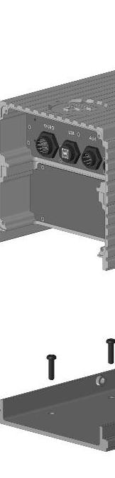

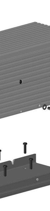

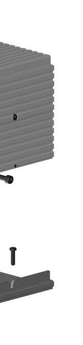


32 DVRS Installation & Programming Guide PART I Figure 13 DVR Mounting Details Full Duplex (With Duplexer) Figure 14 DVR Mounting Details Simplex Only Capable ( Duplexer) Page 21 of 35
33 DVRS Installation & Programming Guide PART I In-Band DVRS Mounting 1. Select the locations of the DVR, in-band filters and MSU such that the nterconnecting cables can reach and there is enough space for securing the side thumbscrews. 2. Using the mounting base as a template, mark the positions of the 12 holes on the mounting surface. 3. Center-punch the spots you have marked and realign the mounting base in position. 4. Secure the mounting bases with six self-drilling screws. 6mm or ¼ screws are recommended. 5. Leave enough room for adequate access to the DVRS connectors and screws. 6. Route the cables throughh the mounting bases ass required. 7. Drop the DVR and the tch Filter Assembliess into the mounting bases and slide each back. 8. Secure the DVR assembly with the two 8mm machine screws and split spring lock washers provided. 9. Tighten the two 8mm machine screws with the 6mm Allen Key. The required tightening torque is 21.7 Nm (16 lb in). 10. Repeat step 9 to install the tch filter assembly. 11. Connect all cables and then secure the front andd rear DVR covers by tightening the 4 thumbscrewss provided. 12. Secure the rear tch Filter cover by tightening the 4 thumbscrews provided. Page 22 of 35
34 DVRS Installation & Programming Guide PART I Mounting the Mobile Radio For detailed Mobile Radio and accessories Installation Instructions, pleasee refer to the Installation Manuals available from Motorola. Ensure the Remote Mount MSU is mounted beside the DVR within the range of the DVRS cabling. NOTE: Unless special cabling length is specified upon placing an order,, the DVR is shipped with a standard 3ft-long interconnect cable between the MSU and DVR. Connecting the DVRS Cables NOTE: The DVRS antenna ports (both DVR and APX sides) are mini UHF femalee and require antennas with matching mini UHF male terminations. Simplex Cross-Band Models (without any filters) require an antenna with TNC male connector. DVR RADIO USB U AUX POWER RX TX RX TX ANTEN Figure 15 DVR Connectors - Front and Back View (With Duplexer) ) Power Cable IMPORTANT! The DVRS operates only in negative starting the installation, make sure correct. ground, + 12VDC electrical systems. Before that the ground polarity of the vehicle is 1. Determine power cable routing between the VRS mounting location and the vehicle battery. 2. Locate an existing hole with a grommet in the vehicle firewall. If a firewall hole does not exist, drill an access hole in the firewall for cable passage. Install a grommet in the hole to avoid damage to the power cable. 3. From the inside of the vehicle, feed the red lead (without lug attached) through the access hole into the engine compartment. 4. Find a grounding point close to the VRS location. Shorten the black lead. Page 23 of 35
35 DVRS Installation & Programming Guide PART I 5. Strip the end of the black lead as required. Crimp the large lug on the black lead and connect it to the vehicle chassis ground. 6. Trim the red lead to the proper length. Strip the end of the red lead as required. Crimp the large lug on the red lead. 7. Locate the fuse holder as close to the battery ass possible and away from hot engine parts. Cut the red lead at this location and pull both cut ends through the fuse holder holes. Strip both ends and crimp the metal fuse holder ends on both ends. Install the fuse and close the fuse holder. 8. Connect the red lead lug to the battery positive (+ +) terminal. RF Cables The following RF cables are provided with the respective In-Band DVR Models: PN 7W083X W083X16-01 Order Code DDN9034 DDN9033 Description MSU to in-band filtering DVR Ant to In-Band Filtering Length 3 feet 3 feet Connectors Mini UHF male Mini UHF male DVR Models All In-Band Models. VHF & UHF In-Band Models. Table 6 DVRS RF Cables Control Cables The following Control Cable types are available: Part Number: Order Code Description Connector Type - Mobile Radio End Connector Type - DVR End Length Table 7 DVRS Control Cable Types 7W083X05-01 DDN9028 Standard MSU DVR Control Cable DB25 Male Over-molded 20-PIN Female 915mm (36 ) (Custom lengths up to 7620mm = 300 are available) 1W083B09-01 DDN9029 Optional MSU DVR Control Cable. Used when the MSU is interfaced to Siren HLN1439C DB25 Male to MSU DB25 Female to Siren Cable Over-molded 20-PIN Female 915mm (36 ) Page 24 of 35
 is required per DVRS Installation.")
36 DVRS Installation & Programming Guide PART I Figure 16 DVR-to-- MSU Control Cable 7W083X05-01 Figure 17 DVR-to-- MSU (with Siren) Control Cable 1W083B09-01 NOTE: Only one of the above Control Cables (shown on Figure 16 and Figure 17) is required per DVRS Installation. Page 25 of 35
37 DVRS Installation & Programming Guide PART I Option Cables The DVR Auxiliary port provides three Relay Driver Output Ports and two Switch Contact Input Ports, which can be interfaced to external logic. The DVR Auxiliary port is extended by the DVR Auxiliary jumper cable PN 7W083X06. Figure 18 DVR Auxiliary Cable - 7W083X06-01 In-Band DVRS Option Cables RF Switch Cable Connect the DB9 Female connector of the 7W083X09 cable to the DB9 male port labeled TO AUX which is located on the DVRS In-Band filtering shelf. Connect the other end of the 7W083X09 cable to the matching DB15 connector of the 7W083X06 cable. Connect the over-molded 9-pin connector of 7W083X06 to the matching DVR connector labeled AUX. To enable the RF Switch operation, the MSU RF F Bypass Switch box in the DVRS Hardware Setup menu must be checked. Other Option Cables To connect other external logic to the DVR, the DB15 connector of the RF Switch cable 7W083X09 can be opened and extra wires added to the corresponding pins as described in the DVR Options section of this document. Cross-Band DVRS Option Cables Connect the over-molded 9-pin connector of cable PN 7W083X06 to the matching DVR connector labeled AUX. Terminate the required external logic option cable (provided by others) with a DB15 male connector with the required pin out and connect it to the DB15 female connector of the 7W083X06 cable. The external logic options must be enabled in the DVR personality as described in the DVR Options section of this document. Page 26 of 35


38 DVRS Installation & Programming Guide PART I Figure 19 In-Band VHF or UHF DVRS Interconnect Cabling - Front Figure 20 In-Band VHF or UHF DVRS Interconnect Cabling - Back Page 27 of 35


")


39 DVRS Installation & Programming Guide PART I 1 2 Figure 21 In-Band DVRS (700 or 800MHz) Interconnect Cabling - Front Figure 22 In-Band DVRS (700 or 800MHz) Interconnect Cabling - Back Page 28 of 35


40 DVRS Installation & Programming Guide PART I 1 2 Figure 23 Cross-Band Full Duplex & Simplex Capablee DVRS Interconnect Cabling - Front 2 Figure 24 Cross-Band Full Duplex & Simplex Capablee DVRS Interconnect Cabling Back Page 29 of 35


41 DVRS Installation & Programming Guide PART I 2 1 Figure 25 Cross-Band Simplex Only Capable DVRS Interconnect Cabling Front 2 Figure 26 Cross-Band Simplex Only Capable DVRS Interconnect Cabling Back Page 30 of 35
Futurecom Systems Group, ULC. DVR APX Series P25 Interface Installation & Programming Guide
 Futurecom Systems Group, ULC DVR Installation & Programming Guide DVRS Installation & Programming Guide PART I NOTES Page 2 of 152 DVRS Installation & Programming Guide PART I Related Publications Publication
MOBEXCOM P25 DIGITAL VEHICULAR REPEATER. Transportable DVRS Installation Guide 8F083X02 Rev. 5
 MOBEXCOM P25 DIGITAL VEHICULAR REPEATER Transportable DVRS Installation Guide 8F083X02 Rev. 5 NOTES 8F083X02 Rev. 5 Page 2 of 21 Contents Contents... 3 Foreword... 5 Terminology Used... 5 Manual Revisions...
Futurecom Systems Group, ULC. PDR8000 Portable Digital Repeater Programming Guide. Document: 8K088X04 Revision: R2.
 Futurecom Systems Group, ULC PDR8000 Portable Digital Repeater Programming Guide Document: 8K088X04 Revision: R2.0 Date: 2017-10-02 Document Revisions Revision Date & References R1.0 2017-05-24 Initial
MOBEXCOM P25 DIGITAL VEHICULAR REPEATER
 MOBEXCOM P25 DIGITAL VEHICULAR REPEATER 8A083X20 () Rev 16 April 2014 NOTES 8A083X20 Rev. 16 April 2014 Page 2 of 70 Contents Contents...3 Foreword...8 Manual Revisions...8 Firmware...9 Computer Software
Ordering Guide. VRX1000 Vehicle Radio Extender. 8A087X01 Revision 2.9. December 19, 2018
 Ordering Guide VRX1000 Vehicle Radio Extender 8A087X01 Revision 2.9 Contents Revision History... 3 Ordering Instructions PLEASE READ CAREFULLY... 4 Important Notes... 5 1. Mobile Radio Type... 6 2. VRX1000
Ordering Guide. VRX1000 Vehicle Radio Extender. 8A087X01 Revision 2.7. April 20, 2018
 Ordering Guide VRX1000 Vehicle Radio Extender 8A087X01 Revision 2.7 Contents Revision History... 3 Ordering Instructions PLEASE READ CAREFULLY... 4 Important Notes... 5 1. VRX1000 Base Transceiver Frequency
Ordering Guide. P25 Digital Vehicular Repeater System. 8A083X31 Revision 3.4. December 19, 2018
 Ordering Guide P25 Digital Vehicular Repeater System 8A083X31 Revision 3.4 Important Notes 1. Only the frequency bands shown in this ordering guide are available as standard configurations. For custom
Technical Support, End User License & Warranty Information
 Technical Support, End User License & Warranty Information How to get Technical Support Pazzles provides free Technical Support for your Inspiration Vūe for a period of 1 year from the date of purchase.
Futurecom Systems Group, ULC. DVRS User s Guide. June 2018 Page 1 of 94
 Futurecom Systems Group, ULC DVRS June 2018 Page 1 of 94 NOTES June 2018 Page 2 of 94 Contents Contents... 3 Foreword... 8 Manual Revisions... 8 Firmware... 9 Computer Software Copyrights... 9 Document
User s Guide FM Transmitter
 TM 12-634 User s Guide FM Transmitter Please read this user s guide before using your new FM Transmitter. 12-634_en.indd 1 Package contents FM Transmitter USB Cable User s Guide Quick Start IMPORTANT SAFETY
Radio Remote(s) (Installation Manual)
 (Installation Manual)") Radio Remote(s) (Installation Manual) 87 Progress Avenue, Tyngsboro, MA 01879, USA Phone (978) 649-4ECU Fax (978) 649-8363 http://www.qtiusa.com Trademarks, Version, Printing, and Copyright Trademarks
Radio Remote(s) (Installation Manual) 87 Progress Avenue, Tyngsboro, MA 01879, USA Phone (978) 649-4ECU Fax (978) 649-8363 http://www.qtiusa.com Trademarks, Version, Printing, and Copyright Trademarks
DVRS BERKS COUNTY APX TM 7500 O5. Select image from Photo Library Insert and resize image to fill up this white area Send (image) to back
 to back") APX Two-Way Radios APX TM 7500 O5 DVRS Select image from Photo Library Insert and resize image to fill up this white area Send (image) to back BERKS COUNTY Copyrights/Disclaimer Computer Software Copyrights
APX Two-Way Radios APX TM 7500 O5 DVRS Select image from Photo Library Insert and resize image to fill up this white area Send (image) to back BERKS COUNTY Copyrights/Disclaimer Computer Software Copyrights
Copyright Teletronics International, Inc. Patent Pending
 Copyright 2003 By Teletronics International, Inc. Patent Pending FCC NOTICES Electronic Emission Notice: This device complies with Part 15 of the FCC rules. Operation is subject to the following two conditions:
RFTX-1 Installation Manual
 RFTX-1 Installation Manual complete control Universal Remote Control RFTX-1 Installation Manual 2009-2014 Universal Remote Control, Inc. The information in this Owner s Manual is copyright protected. No
Gypsy Statement of Limited Warranty. Part 1 General Terms
 Gypsy Statement of Limited Warranty Part 1 General Terms This Statement of Limited Warranty includes Part 1 General Terms, and Part2 Warranty Information. The warranties provided by PROVO CRAFT AND NOVELTY,
X80 Activator. User's Manual. Version 1.1.
 X80 Activator User's Manual Version 1.1 www.buckeyecam.com Table of Contents 1. Warnings... 3 2. Overview... 4 3. Getting Started... 5 4. Using the Activate Button... 7 5. Wiring... 8 6. Specifications...
Easy-Link Plus Version 2.2
 Easy-Link Plus Easy-Link Plus Version 2.2 Copyright 1994-2000 IDA Corporation All Rights Reserved This device complies with Part 15 of the FCC Rules. Operation is subject to the following two conditions:
AIS 300 Installation Instructions
 Use these instructions to install the Garmin AIS 300 Automatic Identification System (AIS) Class B receiver device. Compare the contents of this package with the packing list on the box. If any pieces
One Shelf, Wall Mounted A/V Component Stand Installation Guide Model: EX101SS
 One Shelf, Wall Mounted A/V Component Stand Installation Guide Model: EX0SS For technical assistance or troubleshooting please call -855-994-3832. This product is intended for use only with Audio/Video
Warranty Terms & Conditions
 Warranty Terms & Conditions Is my guitar under warranty? How long, what specific parts? Ibanez Electric Guitars and Basses Limited Warranty Ibanez Electric Guitars and Basses sold in the United States
MEDICINE LICENSE TO PUBLISH
 MEDICINE LICENSE TO PUBLISH This LICENSE TO PUBLISH (this License ), dated as of: DATE (the Effective Date ), is executed by the corresponding author listed on Schedule A (the Author ) to grant a license
Copyright Teletronics International, Inc. Patent Pending
 Copyright 1999 by Teletronics International, Inc. Patent Pending All Rights Reserved. No part or parts of this document may be reproduced, translated, stored in any electronic retrieval system, or transmitted,
CDT. Service and Installation Manual. Manual Revision Oct 2014
 CDT Service and Installation Manual Manual Revision Oct 2014 2014 Cimarron Technologies Corp., Escondido, CA, USA. All rights reserved. No part of this manual may be reproduced in any way without the express
Tilting, Swiveling & Rotating Flat Panel Wall Mount
 Tilting, Swiveling & Rotating Flat Panel Wall Mount Model: VXA980TC +5 to -5 +5 to -5 Supports most 0-80 Flat Panel TVs Maximum Weight Capacity: 32 lbs. Supports VESA Sizes up to 600x500 For technical
SureCall TM CM800 65dB
 SureCall TM CM800 65dB Cellular Band Building Repeater User Manual Model: CM800 FCC ID: RSNCM2000 CONTENTS OF THE PACKAGE fdgbsddg 1. CM800 Amplifier with connectors: N female type 2. Mounting Kit 3. 110V
Inline Antenna Signal Amplifier
 1500528 User s Guide Inline Antenna Signal Amplifier We hope you enjoy your In-Line Antenna Signal Amplifier from RadioShack. Please read this user s guide before using your new signal amplif ier. Package
Tilting Flat Panel Wall Mount Installation Guide
 Tilting Flat Panel Wall Mount Installation Guide Model: A580TM Easy installation Built-in level for easy positioning Safety bolts lock the TV on the mount Easy to adjust tilt angles: +5 to -15 degrees
SureCall TM CM dB Dual Band Universal Inbuilding Repeater
 SureCall TM CM2020 65dB Dual Band Universal Inbuilding Repeater User Manual Model: CM2020 65dB FCC ID: RSNDUAL-65UNDER CANADA IC:7784A-D65UNDER wpsantennas.com 1-877-594-5766 CONTENTS OF THE PACKAGE fdgbsddg
PixController, Inc. Wireless Vibration Sensor For Indoor and Outdoor Use
 PixController, Inc. Wireless Vibration Sensor For Indoor and Outdoor Use Model: SEN-440 User s Manual Version 1.00 WARRANTY REGISTRATION PixController, Inc. warrants products sold by it and guarantees
ASSEMBLY INSTRUCTIONS
 AVSC-2123 Audio Video System ASSEMBLY INSTRUCTIONS PATENT PENDING FOR YOUR SAFETY, PLEASE FOLLOW THESE PRECAUTIONS:! ALWAYS REMOVE THE TV AND OTHER EQUIPMENT FROM THE FURNITURE PRIOR TO MOVING THE ASSEMBLED
Radio Remote Controls Manual K Series
 Radio Remote Controls Manual K Series PN 52764 2010.12.20 Rev. 2 K Series radio control manual 1 Conductix Incorporated The technical data and images which appear in this manual are for informational purposes
supplied o-ring grease can be used to hold the o-ring in the groove during installation.
 42GOXX16A4-XT-1-1 ANTENNA GUIDE OM-20000158 Rev 1 December 2013 The 42G1215A-XT-1 is an active GPS antenna that receives the GPS L1 1575.42 MHz frequency, the GLONASS L1 1602 1626 MHz frequencies, the
Model DB Disc Caliper Brake AIR CHAMP PRODUCTS. User Manual. (i) MTY (81)
 MTY (81)") DIST. AUTORIZADO MEX (55) 53 63 3 3 QRO (44) 95 7 60 MTY (8) 83 54 0 8 AIR CHAMP PRODUCTS User Manual Model DB Disc Caliper Brake (i) FORM NO. L-00-G-030 MEX (55) 53 63 3 3 MTY (8) 83 54 0 8 DIST. AUTORIZADO
DIST. AUTORIZADO MEX (55) 53 63 3 3 QRO (44) 95 7 60 MTY (8) 83 54 0 8 AIR CHAMP PRODUCTS User Manual Model DB Disc Caliper Brake (i) FORM NO. L-00-G-030 MEX (55) 53 63 3 3 MTY (8) 83 54 0 8 DIST. AUTORIZADO
FP-4855 Flat Panel Television Stand ASSEMBLY INSTRUCTIONS
 FP-4855 Flat Panel Television Stand ASSEMBLY INSTRUCTIONS Patent Pending Italian Designed A Product of China Do not discard these instructions M-1_051607v3 Bell O International Corp. will not be responsible
Tilting & Swiveling Flat Panel Wall Mount Installation Guide Model: AXS2040
 Tilting & Swiveling Flat Panel Wall Mount Installation Guide Model: AXS2040 20-40 66 lbs. Supports VESA sizes up to: 200x200 For technical assistance or troubleshooting please call 1-855-994-2825 or visit
Tension Control Clutch Model TCC-7
 AIR CHAMP PRODUCTS User Manual Tension Control Clutch Model TCC-7 (i) FORM NO. L-20176-B-0501 In accordance with Nexen s established policy of constant product improvement, the specifications contained
900MHz Digital Hybrid Wireless Outdoor Speakers
 4015004 900MHz Digital Hybrid Wireless Outdoor Speakers User s Manual This 900 MHz digital hybrid wireless speaker system uses the latest wireless technology that enables you to enjoy music and TV sound
DA6002D-DA10004D. INSTALLATION / OWNER'S MANUAL Mobile Power Amplifiers
 DA6002D-DA10004D INSTALLATION / OWNER'S MANUAL Mobile Power Amplifiers Preparation Please read entire manual before installation. Due to the technical nature of amplifiers, it is highly recommended that
o-ring grease can be used to hold the o-ring in the groove during installation.
 42G1215A-XT-1-2 and 42G1215A-XT-1-3 ANTENNA GUIDE OM-20000154 Rev 1 December 2013 The 42G1215A-XT-1-3 and 42G1215A-XT-1-2 are active antennas designed to operate at the GPS L1 and L2 frequencies, 1575.42
DA560D COMPACT SERIES. INSTALLATION / OWNER'S MANUAL Mobile Power Amplifiers
 DA560D COMPACT SERIES INSTALLATION / OWNER'S MANUAL Mobile Power Amplifiers Preparation Please read entire manual before installation. Due to the technical nature of amplifiers, it is highly recommended
Single Flex and Double Flex Couplings (i)
") Single Flex and Double Flex Couplings (i) FORM NO. L00G00 In accordance with Nexen s established policy of constant product improvement, the specifications contained in this manual are subject to change
Single Flex and Double Flex Couplings (i) FORM NO. L00G00 In accordance with Nexen s established policy of constant product improvement, the specifications contained in this manual are subject to change
HDTV Antenna. Contemporary Indoor. User s Guide
 User s Guide 15-246 Contemporary Indoor HDTV Antenna Thank you for purchasing your HDTV/FM HD Radio Antenna from RadioShack. Please read this user s guide before installing, setting up, and using your
View Terms and Conditions: Effective 12/5/2015 Effective 6/17/2017
 View Terms and Conditions: Effective 12/5/2015 Effective 6/17/2017 Comerica Mobile Banking Terms and Conditions - Effective 12/5/2015 Thank you for using Comerica Mobile Banking combined with your device's
Using the USB Output Port to Charge a Device
 Table of Contents ----------------------------------- 2 Features ----------------------------------------------- 3 Controls and Functions ---------------------------------- 4 ER210 Power Sources -----------------------------------
BE369 Deadbolt Installation Instructions
 1 BE369 Deadbolt Installation Instructions Important Information Lock Programming Code Alternate Faceplate six (6) digits User Code A User Code B four (4) digits four (4) digits Web Support: www.part2.schlage.com
PTT- Z or PTT-U PUSH-TO-TALK Specification
 Federal Communication Commission Interference Statement This equipment has been tested and found to comply with the limits for a Class B digital device, pursuant to Part 15 of the FCC Rules. These limits
DA604D DA954D DA501D DA801D COMPACT SERIES. INSTALLATION / OWNER'S MANUAL Mobile Power Amplifiers
 DA604D DA954D DA501D DA801D COMPACT SERIES INSTALLATION / OWNER'S MANUAL Mobile Power Amplifiers Preparation Please read entire manual before installation. Due to the technical nature of amplifiers, it
o-ring grease can be used to hold the o-ring in the groove during installation.
 42G1215A-XT-1 ANTENNA GUIDE OM-20000152 Rev 1 December 2013 The 42G1215A-XT-1 is an active antenna designed to operate at the GPS L1 and L2 frequencies, 1575.42 and 1227.60 MHz. The antenna is aircraft
ER200 COMPACT EMERGENCY CRANK DIGITAL WEATHER ALERT RADIO OWNER S MANUAL
 ER200 COMPACT EMERGENCY CRANK DIGITAL WEATHER ALERT RADIO OWNER S MANUAL Table of Contents -------------------------------------- 2 Features ----------------------------------------------- 3 Controls and
00108/00110 INSTRUCTION MANUAL
 00108/00110 INSTRUCTION MANUAL Removable and Adjustable Mudflap System IMPORTANT! Please Read this Instruction Booklet prior to assembly of your Rock Tamer Kit. IMPORTANT! Exhaust Systems Note: Any modifications
XPR522 XPR540. XPR SERIES INSTALLATION / OWNER'S MANUAL Mobile Power Amplifiers
 XPR522 XPR540 XPR SERIES INSTALLATION / OWNER'S MANUAL Mobile Power Amplifiers Preparation Please read entire manual before installation. Due to the technical nature of amplifiers, it is highly recommended
TI Designs: Biometric Steering Wheel. Amy Ball TIDA-00292
 www.ti.com 2 Biometric Steering Wheel - -Revised July 2014 www.ti.com TI Designs: Biometric Steering Wheel - -Revised July 2014 Biometric Steering Wheel 3 www.ti.com 4 Biometric Steering Wheel - -Revised
Installation Manual Roof Zone Ladder Rack
 Installation Manual Roof Zone Ladder Rack 102113,E1346 Installation Time: About 90 minutes. Depending on truck and Do-it-Yourself experience level Tools Required: Electric Drill with 1/2 Chuck 1/2 & 7/32
SIR-WRR1. User's Guide SIRIUS Echo Antenna. Signal Repeater System Accessory
 SIR-WRR1 User's Guide SIRIUS Echo Antenna Signal Repeater System Accessory Desktop SIRIUS Docking Echo Station Antenna FCC NOTICE: This device complies with part 15 of the FCC Rules and with RSS-210 of
Comfort 10S Wall Hardwire Installation and Operations Manual
 Comfort 10S Wall Hardwire Installation and Operations Manual 10/24/2012 REQUIRED TOOLS STARHEAD SCREWDRIVERS DRILL & BIT FLAT HEAD SCREWDRIVERS ALLEN KEY PENCIL MEASURING TAPE LEVEL ELECTRICAL REQUIREMENTS:
Owner s Manual & Safety Instructions
 Owner s Manual & Safety Instructions Save This Manual Keep this manual for the safety warnings and precautions, assembly, operating, inspection, maintenance and cleaning procedures. Write the product s
Installation Instructions
 Articulating Hex Monitor Mount Stand Installation Instructions UNPACKING Carefully open the carton, remove contents, and place them on a protected surface to avoid damage. Check the parts and the Supplied
User Manual. ProRF Encoder Transmitter & Receiver
 User Manual ProRF Encoder Transmitter & Receiver WARRANTY Accurate Technology, Inc. warrants the ProScale Systems against defective parts and workmanship for 1 year commencing from the date of original
User Manual January Opticom Infrared System RC790 Remote Coding Unit
 User Manual January 2010 Opticom Infrared System RC790 Remote Coding Unit 1. Description The Opticom Infrared System RC790 Remote Coding Unit is used to remotely program Model 794 series LED emitters.
Instruction Sheet REB SERIES. Rotating Sliding Base REB18
 Instruction Sheet REB SERIES Rotating Sliding Base REB14 REB18 THANK YOU Thank you for purchasing the REB Series Rotating Sliding Base. Please read these instructions thoroughly before installing this
The BioBrick Public Agreement. DRAFT Version 1a. January For public distribution and comment
 The BioBrick Public Agreement DRAFT Version 1a January 2010 For public distribution and comment Please send any comments or feedback to Drew Endy & David Grewal c/o endy@biobricks.org grewal@biobricks.org
Contents. Page English 1. French. Spanish. Reset of MIN/MAX records 915 MHz Reception Mounting Care and Maintenance Warranty Information
 Contents Language Page English 1 French Spanish WIRELESS 915 MHz TEMPERATURE STATION Instruction Manual TABLE OF CONTENTS Topic Page Inventory of Contents Features Setting Up Battery Installation Function
Futurecom Systems Group, ULC. VRX1000 Functional Description
 Futurecom Systems Group, ULC Functional Description NOTES June 2018 Page 2 of 74 Contents Contents... 3 List of Tables... 6 List of Figures... 6 Manual Revisions... 7 Computer Software Copyrights... 7
14 CHANNEL FAMILY RADIO SYSTEM MODEL # FR142
 14 CHANNEL FAMILY RADIO SYSTEM MODEL # FR142 2001 Audiovox Electronics Corp., Hauppauge, NY 11788 Printed in China 128-6020 052FR142104 BEFORE OPERATING THIS PRODUCT PLEASE READ THESE INSTRUCTIONS COMPLETELY
g GETTING STARTED D PC System Requirements Computer: Pentium 90 MHz processor or equivalent.
 g GETTING STARTED D PC System Requirements Computer: Pentium 90 MHz processor or equivalent. Operating Systems: Windows 2000, Windows XP, or Windows Vista. Memory: 16 MB of RAM Controls: A keyboard and
Ordering Information. Stepping Relay Unit G9B. Model Number Legend
 Stepping Relay Unit CSM DS_E_4_1 Ideal for Controlling Pumps and Production Lines with Six or Twelve Stepping Circuits Built-in relays switch 2 A at 250 VAC or 30 VDC. Initialization of stepping with reset
ATTENTION: PLEASE READ AND UNDERSTAND ALL INSTRUCTIONS AND WARNINGS BEFORE ASSEMBLING, INSTALLING OR USING THIS PRODUCT.
 INSTALLATION MANUAL Models 96111-3-02 & 96511-3-02 Bulkheads for 2014 and Later Ford Transit Connect Vans ATTENTION: PLEASE READ AND UNDERSTAND ALL INSTRUCTIONS AND WARNINGS BEFORE ASSEMBLING, INSTALLING
Low Voltage Brushed Motor System
 Low Voltage Brushed Motor System Tests performed: 1. RPM vs Output Voltages 2. Thermal Imaging 3. Output Voltage, Output Current, and Direction Voltage for100% duty Cycle a. Forward Direction b. Reverse
ATTENTION: PLEASE READ AND UNDERSTAND ALL INSTRUCTIONS AND WARNINGS BEFORE ASSEMBLING, INSTALLING OR USING THIS PRODUCT.
 PLAN YOUR VAN (TIPS FOR FASTER INSTALLATION) Installing your Transit bulkhead is very clear cut following these instructions. Before cutting or drilling in the floor, verify the location of you gas tank,
380 SERIES REPAIR PARTS INDEX. NOTE! Read and understand the pump and motor instructions before attempting to install, disassemble or repair the pump.
 380 SERIES REPAIR PARTS INDEX NOTE! Read and understand the pump and motor instructions before attempting to install, disassemble or repair the pump. Part # A-03-222 2014 Pentair Ltd. 07/31/14 SECTION
Where to Obtain More Information
 BCI25D 10/10/2 4:33 PM Page 1 General Explanation of BCi25D The BCi25D is an APCO Project 25 Digital Card that enables you to monitor APCO Project 25 Systems. When the BCi25D card is installed into either
500S Smart Antenna Installation and Operation Manual. P/N Rev. A 09/17 E29808
 500S Smart Antenna Installation and Operation Manual P/N 016-0171-668 Rev. A 09/17 E29808 Copyright 2017 1 Disclaimer While every effort has been made to ensure the accuracy of this document, Raven Industries
Installation Procedures For 2013 Mustang V-6 and 5.0
 Installation Procedures For 2013 Mustang V-6 and 5.0 Warning: Please read directions completely before starting. If you have any questions please contact BMPP before beginning your installation.. Also
2001A. 200KHz Function Generator Instruction Manual. 99 Washington Street Melrose, MA Phone Toll Free
 2001A 200KHz Function Generator Instruction Manual 99 Washington Street Melrose, MA 02176 Phone 781-665-1400 Toll Free 1-800-517-8431 Visit us at www.testequipmentdepot.com WARRANTY Global Specialties
MIRAGE BD-38-G DUAL BAND POWER AMPLIFIER
 MIRAGE BD-38-G DUAL BAND POWER AMPLIFIER MIRAGE BD-38-G Dual Band Amplifier INTRODUCTION: The Mirage BD-38-G is a 80/60 watt dual band power amplifier for use with today's dual band handie talkies operating
VAN STORAGE SOLUTIONS FOR THE WAY YOU WORK
 WWW.WEATHERGUARD.COM VAN STORAGE SOLUTIONS FOR THE WAY YOU WORK Weather Guard / KNAACK 420 E. Terra Cotta Ave. Crystal Lake, IL 60014 USA 800-456-7865 (Toll Free) 800-334-2981 (Fax) Knaack.OrderEntry@wernerco,.com
Guide. Installation. Wilson Electronics, Inc. Direct Connection High Power iden Amplifi er 800 MHz Band. Contents:
 Amplifier Installation Guide Direct Connection High Power iden Amplifi er 800 MHz Band Contents: Guarantee and Warranty 1 Before Getting Started / How it Works 3 Installing a Wilson Outside Antenna - In-Vehicle
RPR-265. Power Rack (Cage)
") ASSEMBLY INSTRUCTIONS 3 3/4" RPR-5 50 3/4" 51 1/4" Power Rack (Cage) TuffStuff Fitness Equipment, Inc. 15 E. Franklin Avenue Pomona, CA 9166, USA Ph: 909-6-1600 Fax: 909-6-496 E-mail: service@tuffstuff.net
ASSEMBLY INSTRUCTIONS 3 3/4" RPR-5 50 3/4" 51 1/4" Power Rack (Cage) TuffStuff Fitness Equipment, Inc. 15 E. Franklin Avenue Pomona, CA 9166, USA Ph: 909-6-1600 Fax: 909-6-496 E-mail: service@tuffstuff.net
XIA3145 INSTALLATION/OWNER S MANUAL 2/1-Channel Mobile Power Amplifier
 XIA3145 INSTALLATION/OWNER S MANUAL 2/1-Channel Mobile Power Amplifier XIA3145 INSTALLATION Preparation Please read entire manual before installation. Due to the technical nature of amplifiers, it is highly
Installation Procedures 2015 Corvette C-7 Z06 With Carbon Fiber Kit SNS 50a
 Installation Procedures 2015 Corvette C-7 Z06 With Carbon Fiber Kit SNS 50a Warning: Please read directions completely before starting. If you have any questions please contact BMPP before beginning your
Radio Remote Controls Manual K Series
 Radio Remote Controls Manual K Series 1 PN 52764 2010.12.20 Rev. 2 K SERIES RADIO CONTROL MANUAL Conductix Incorporated The technical data and images which appear in this manual are for informational purposes
Field Hub Installation Guide. P/N Rev. C 05/15
 Field Hub Installation Guide P/N016-0171-380 Rev. C 05/15 E21714 Copyright 2015 Disclaimer While every effort has been made to ensure the accuracy of this document, Raven Industries assumes no responsibility
XPA2100 XPA4100 XPA6100. XPA SERIES INSTALLATION/OWNER S MANUAL Mobile Power Amplifiers
 XPA2100 XPA4100 XPA6100 XPA SERIES INSTALLATION/OWNER S MANUAL Mobile Power Amplifiers XPA SERIES INSTALLATION Preparation Please read entire manual before installation. Due to the technical nature of
Installation Procedures Maserati Gran Turismo Sport SNS 85
 Installation Procedures 2012-2017 Maserati Gran Turismo Sport SNS 85 Warning: Please read directions completely before starting. If you have any questions please contact BMPP before beginning your installation.
DXE-NCCFL Receive Filter Sets
 DXE-NCCFL Receive Filter Sets The advanced plug-in filter modules (DXE-NCCFL Series) offer frequency-specific receive system enhancements for the DXE- NCC-1 Receive Antenna Phasing Controller. All filter
Signal Isolation Module. Instruction Manual SIM
 Signal Isolation Module Instruction Manual SIM200-000 Table of Contents 1. General Description... 3 2. Specifications... 3 2.1 Electrical... 3 2.2 Physical... 4 3. Installation... 4 3.1 Wiring Guidelines...
Owner s Manual & Safety Instructions
 Owner s Manual & Safety Instructions Save This Manual Keep this manual for the safety warnings and precautions, assembly, operating, inspection, maintenance and cleaning procedures. Write the product s
Installation Guide. Delphi XM FM Direct Accessory. For Use With Roady2 and SKYFi2 Satellite Radio Receivers
 Delphi XM FM Direct Accessory Installation Guide For Use With Roady2 and SKYFi2 Satellite Radio Receivers Warning: This guide and the user guide that came with your Roady2 or SKYFi2 contain important safety
Model 935A. Dual Tone Sender INSTRUCTION MANUAL
 Model 935A Dual Tone Sender INSTRUCTION MANUAL Monroe Electronics 100 Housel Ave Lyndonville NY 14098 800-821-6001 585-765-2254 fax 585-765-9330 monroe-electronics.com Printed in USA Copyright Monroe Electronics,
Datasheet of SAW Device
 Datasheet of SAW Device SAW Duplexer for Band1 / Unbalanced / LR /216 Murata PN: SAYRF1G95GEFA Feature High Band34 Attenution High Isolation LTE-A Note : Murata SAW Component is applicable for Cellular
TLKR T60 OWNER'S MANUAL EN DE FR IT ES PR NL DA NO TU PL SV RU
 TLKR T60 OWNER'S MANUAL EN DE FR IT ES PR NL DA NO TU PL SV RU SF 1 PRODUCT SAFETY AND RF EXPOSURE FOR PORTABLE TWO-WAY RADIOS! Caution ATTENTION! Before using this product, read the RF energy awareness
Two Element Phased Vertical Array System
 Two Element Phased Vertical Array System COM-PVS-160/80/40/30/20 COM-PVS-2-INS-Revision 7 COMTEK SYSTEMS 2011 P.O. Box 1491 - Akron, OH 44309-1491 USA Phone: (800) 777-0703 Technical Support and International:
ACT-IR220Li/220LN IrDA Serial Port Adapter
 ACT-IR220Li/220LN IrDA Serial Port Adapter Product Specification Summary ACTiSYS Corp. 48511 Warm Springs Blvd, Suite 206 Fremont, CA 94539, USA TEL: (510) 490-8024, FAX: (510) 623-7268 E-Mail: irda-support@actisys.com
Line 6 L I M I T E D R E F URBISH E D (B-ST O C K) W A RR ANT Y
 W A RR ANT Y") Line 6 L I M I T E D W A RR A N T Y PO L I C Y PLEASE READ THIS DOCUMENT CAREFULLY. IT CONTAINS IMPORTANT INFORMATION ABOUT YOUR RIGHTS AND OBLIGATIONS, AS WELL AS LIMITATIONS AND EXCLUSIONS THAT MAY APPLY
Line 6 L I M I T E D W A RR A N T Y PO L I C Y PLEASE READ THIS DOCUMENT CAREFULLY. IT CONTAINS IMPORTANT INFORMATION ABOUT YOUR RIGHTS AND OBLIGATIONS, AS WELL AS LIMITATIONS AND EXCLUSIONS THAT MAY APPLY
Ditch Witch 750 Tracker Specs Provided by FOREWORD
 750/752 Display - FOREWORD 1 Ditch Witch 750 Tracker Specs Provided by www.aaatesters.com FOREWORD This manual is an important part of your equipment. It provides safety information and operation instructions
COMBILOG ANTENNA MODEL AC MHz. rev: 0202
 COMBILOG ANTENNA 30-2000 MHz MODEL AC-220 rev: 0202 WARRANTY All equipment manufactured by Com-Power Corporation is warranted against defects in material and workmanship for a period of two (2) years from
MaxLite LED Self-Driven LiteBars
 Accessories Length: 4, 12, 40 Connector Box Straight Joiner Wire Joiner Mounting Clip Distribution Box Left Joiner Wire Joiner with Plug length: 40 Magnet Bracket Right Joiner End Cap Rotation Bracket
Installation Procedures 2018 Mustang GT & EcoBoost SNS 135
 Installation Procedures 2018 Mustang GT & EcoBoost SNS 135 Warning: Please read directions completely before starting. If you have any questions, please contact BMPP before beginning your installation.
Datasheet of SAW Device
 Datasheet of SAW Device SAW Single Filter for Band2 / Unbalanced / 5pin /1109 Murata PN: SAFFB1G96AB0F0A Feature GSM1900/Band2 Rx Note : Murata SAW Component is applicable for Cellular /Cordless phone
TARGETuner Antenna Management System for Screwdriver Antennas
 TARGETuner Antenna Management System for Screwdriver Antennas www.westmountainradio.com 1020 Spring City Drive Waukesha, WI 53186 262-522-6503 sales@westmountainradio.com 2014, All rights reserved. All