MCR91508POS 8 Channel receiver with 8 positive output switching
|
|
|
- Erick Watkins
- 6 years ago
- Views:
Transcription


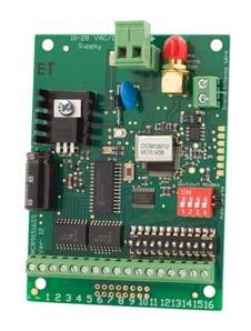
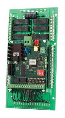
1 MCR91508R, MCR91508POS and MCR91508SS 8-Channel, 915MHz Receiver with Frequency Hopping Features Frequency hopping between 915 to 927MHz Eight channels with simultaneous channel reception Digital Coding, 12-way dipswitch or encrypted coding Crystal Controlled for high stability and accuracy Can operate several transmitters and receivers next to each with no interferences or jamming On-board Red LED to indicate reception of a signal Three versions available - MCR91508R relay output - MCR91508POS positive switching output - MCR91508SS open collector output Wide operating supply voltage and low current consumption ELSEMA Applications Industrial Automation, eg Crane Control, winches, wireless cement truck operation Equipment and machinery control Security and Automotive Systems Advanced home automation i.e. Alarms, gates, doors, garden lights, swimming pool control etc. MCR91508R 8 Channel receiver with 8 relay outputs MCR91508POS 8 Channel receiver with 8 positive output switching MCR91508SS 8 Channel receiver with 8 open collector outputs Description The receivers use fast frequency hopping (FFH) to allow up to eight receivers to be used in the same area. No interference or jamming will occur. The FFH technology is usually used in very expensive equipment with military or medical applications. The receivers use a dual digital coding called Multicode Technology (MCR). This MCR digital coding can be either the 12-way dipswitch or the encrypted coding. The 12-way dip switch allows for simple programming and involves the user to simply match the 12-way dip switch on both the transmitter and receiver. The encrypted coding is a random generated code which is programmed wirelessly to the transmitter and receiver. The encrypted code is usually used when more codes are required for high security applications. See setup instructions for more details on the dipswitch and encrypted coding. The combination of FFH and MCR technology brings you a very sophisticated receiver yet easy to use. Connecting Elsema s ANT915-SMA to the receivers SMA connector will increase the operating range.
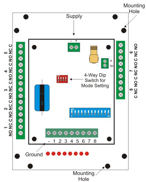
 ELSEMA DIP Switch Mode Settings The output relay will respond in the following manner when receiving the correct signal from a transmitter \"All Momentary\": Relay on, only while correct signal is")
2 Different Modes for each Output Modes are user selectable from the 4-way dip switch, shown below. (Dipswitch 4 is reserved for specific customer mode. Normally not used.) ELSEMA DIP Switch Mode Settings The output relay will respond in the following manner when receiving the correct signal from a transmitter "All Momentary": Relay on, only while correct signal is received "All Latching": Outputs alternate at every correct incoming signal "Momentary & Latching": Outputs 1-4 are momentary & 5-8 are latching "Security Latching on": Outputs will be on until supply to receiver is momentarily interrupted "Momentary & Latching ": Outputs 1-6 are momentary & 7-8 are latching "Momentary & Latching ": Outputs 1-2 are momentary & 3-8 are latching "Momentary & Latching ": Outputs 1-3 are momentary & 4-8 are latching "Security Latching on": Output 1 is security latching & 2-8 are momentary * Dipswitch 4 is reserved Momentary - Output is active for as long as the transmitter button is pressed. This is a standard mode on most automatic gates or garage door openers. Latching Security Latching - Output remains active until next press of the transmitter button. Similar to switching "on" and "off" a light. - Output remains active until power to the receiver is removed. Similar to security alarms and fire alarms. To activate the security latching mode, a link needs to be soldered into the hole marked as latching. Customised Software Custom output modes can be programmed to do special functions. Call Elsema for more details.


3 Products in the Range MCR91501P 1-Channel 915MHz Receiver with Open Collector Output MCR91501PT 1 Channel Receiver with 5- way screw type Terminal MCR91502P 2-Channel 915MHz Receiver with Open Collector Output MCR91502PT 2 Channel Receiver with 5- way screw type Terminal MCR91501R 1-Channel 915MHz Receiver with Relay Output MCR91502R 2-Channel 915 MHz Receiver with Relay Output MCR91503R 3-Channel 915MHz Receiver with Relay Output MCR91504R 4-Channel 915MHz Receiver with Relay Output MCR91508SS 8-Channel 915MHz Receiver with Open Collector Output MCR91508R 8-Channel 915 MHz Receiver with Relay Output MCR91512SS 12-Channel 915MHz Receiver with Open Collector Output MCR91512R 12-Channel 915MHz Receiver with Relay Output MCR91516SS 16-Channel 915MHz Receiver with Open Collector Output MCR91516R 16-Channel 915 MHz Receiver with Relay Output
4 Antenna The receiver has a 50 ohms SMA connector to allow a proper 915MHz antenna to be connected. Elsema stocks the ANT915S-SMA suitable for connection to the receiver. See picture below. Case The C1015 or C1020 case and QM100 mounting bracket can be used to enclose the MCR91508SS receiver into a case. The MCR91508R only needs the C1217 case since the board screws directly onto the case screw studs. These 8-channel receivers can be supplied without a case, this allows the receiver to be integrated according to your needs.

5 Technical Data MCR91508R MCR91508POS MCR91508SS Supply Voltage 10.0 to 28.0 VAC or 11.0 to 36.0 VDC Can use Elsema AC power pack PP12 or PP24 Current Consumption 30 ma stand by at 12 VDC or 50 ma with 1 relay On or 190mA with 8 relays On 30 ma stand by at 12 VDC 30 ma stand by at 12 VDC Frequencies Operating Temperature Range 915 to 928 MHz for Australia 921 to 929 MHz for New Zealand 902 to 928 for United States of America and Canada -5 to 50 C Sensitivity 1uV (For output to switch on) Decoding System On board 12-way code switch (4096 Codes) Encrypted coding (Over 16 million codes) Outputs Antenna Eight change over relay outputs, rated at 8 Amps 240 VAC 50 Volts, 120 ma with all outputs ON ANT915S-SMA for long range applications or piece of approximately 160mm wire for short range applications Chart indicates that eight outputs can be ON simultaneously with each output collector current being 125 ma. Outputs can hold 40 Volts in Off state. Mounting Clip into a QM100 Quick Mount (Only MCR91508SS) Mounting hole size 3.97 mm or 5/32" Dimensions 130 X 94 X 55 mm 95 X 70 X 27 mm Weight 200g 55g 55g Useable Transmitters Operating range All Elsema type MCT915xx series Up to 150 metres. More than 350 metres if SMA version transmitter is used.
6 Block Diagram MCR91508SS
7 MCR91508R
8 Application Notes (MCR91508SS) Care should be taken with the open collector outputs that they are protected from inductive loads. This is done by connecting diodes across your DC inductive load. See diagram below
9 Application Notes (MCR91508POS) View A2982LW datasheet

10 12-Way Dipswitch Setup Instructions To program the transmitter to the receiver you simply match the transmitter and receiver dipswitches. Do not use all dipswitches in the off position. This sets the transmitter to encrypted coding. See encrypted coding instructions. To avoid interference or jamming from other MCT series transmitters make sure that the first 8 dip switches (Dipswitch 1 to 8) are different. The first 8 dipswitches select different frequencies. Advanced Dipswitch Programming Features This feature allows the user to configure very sophisticated systems by mixing and matching different MCT transmitters to MCR receivers. Dipswitches 9, 10, 11 and 12 will determine the position of the first channel on the transmitter and receiver. Other channels are automatically sequentially placed. Example: Using a 4-channel MCR91504 receiver with a 1-channel MCT91501 transmitter. If the MCR91504 has set to the 12 way dipswitch, this sets the receiver first relay (Ch.1) to position 9 i.e The other channel addresses are sequentially placed.


11 This is shown in the table below: To program a 1-button MCT91501 transmitter to receiver relay channel 4 you need to set the transmitters dip switch to To program a 2-button MCT91502 transmitter to receiver relay channel 2 and 3 you need to set the transmitter dip switch to The second button on the transmitter automatically operates relay 3 This example is shown graphically below:
12 Encrypted Coding Setup Instructions To change the transmitter and receiver to encrypted coding set all dipswitches on the 12-way dipswitch to the off position. The encrypted code is a randomly selected code out of 16 million different combinations. The user can change the code by shorting out the Add/Delete pin on the receiver. The orange LED comes on while the Add/ Delete pins are shorted, to confirm the change of code was successful. If this is done all transmitters and receivers need to be programmed again with the new code. Any programming combination is possible, for example transmitter to transmitter, receiver to receiver, transmitter to receiver or visa versa. Programming Steps 1. Make sure all dip switches are in an off position on all transmitters and receivers. 2. Make sure power is connected to the receiver and transmitter. 3. If programming from a receiver, short out the Add/Delete pin to select a random code. The receivers orange LED comes on to confirm the change of code was successful. Do not do this step if you are adding extra transmitters to the receiver since already programmed units will be deleted. 4. Set one of the units, either receiver or transmitter, to broadcast its code. The broadcaster s code will be programmed to the other units. 4a. To broadcast the receivers code make sure all 12 dipswitches are off and then flick dip switch 12 on and then off. This is confirmed by the green LED being on for 10 seconds. 4b. To broadcast the transmitter code hold down button 1 and flick dip switch 12 on and then off. This is confirmed by the green LED being on for 10 seconds. You can release button While broadcasting the code press button 1 on a different transmitter or receiver for 1 second and then release the button. The orange LED will flash twice to confirm successful programming. Broadcasting will be latched on for 10 seconds or stop if any dipswitch is turned on. If orange LED did not flash twice try programming again but move closer to the broadcasting unit. During programming all channels are channelised programmed. That is, button 1 to relay 1, button 2 to relay 2, button 3 to relay 3, etc. This programming method allows a user to program unlimited number of transmitters to the receiver or visa versa. You can even program a transmitter to a new transmitter. You do not need to get access to the receiver. Many of the Multicode technology features are industry firsts, so take your time to read the manuals and let the technology take you away. Watch your competitors follow you Manufactured by Elsema Pty Ltd 31 Tarlington Place, Smithfield NSW 2164 Ph: Fax: Website:
The combination of FFH and MCR technology brings you a very sophisticated receiver yet easy to use.
 MCR91512SS and MCR91512R 12-Channel, 915MHz Receiver with Frequency Hopping Features Frequency hopping between 915 to 928MHz Eight channels with simultaneous channel reception Digital Coding, 12-way dipswitch
MCR91501R 1-Channel, 915MHz Receiver with Frequency Hopping
 MCR91501R 1-Channel, 915MHz Receiver with Frequency Hopping Features Frequency hopping between 915 to 928MHz Digital Coding, 12-way dipswitch or encrypted coding Crystal Controlled for high stability and
MCT91501, MCT91502, MCT91503, MCT MHz Hand Held Transmitter with Fast Frequency Hopping
 MCT91501, MCT91502, MCT91503, MCT91504 915-927 MHz Hand Held Transmitter with Fast Frequency Hopping Features include: Available with 1, 2, 3 or 4 channels, 8, 12 and 16-channels is available with the
FMR ELSEMA 1-Channel 151MHz Receiver - FMR15101
 FMR15101 1-Channel 151MHz Receiver Features Single channel receiver with relay output Supply voltage can be AC or DC Low current consumption Built-in noise or signal strength indicator User can select
FMR ELSEMA 2-Channel 151MHz Receiver - FMR15102
 FMR15102 2-Channel 151MHz Receiver Features Two channel receiver with relay outputs Supply voltage can be AC or DC Low current consumption Built-in noise or signal strength indicator User can select 8
GLR43308 and GLR2708. Setup and programming instructions. for the 8 channel Gigalink receiver. Programming Videos
 GLR43308 and GLR2708 Setup and programming instructions for the 8 channel Gigalink receiver Programming Videos www.elsema.com NOTES IMPORTANT WARNING AND SAFETY INSTRUCTIONS All installations and testing
ELSEMA 1-Channel 433MHz Receiver with 16A Relay Output- GLR
 GLR43301240 1-Channel 433MHz Gigalink, Receiver with Mains AC Supply Features Supply voltage 240VAC (also available in 110-120VAC supply for international markets) High efficiency toroidal transformer
FMR Description
 1-Channel 151MHz FM Receiver with mains AC supply Features Supply voltage 240VAC (also available in 110-120VAC supply for international markets) High efficiency toroidal transformer High capacity output
ELSEMA GLR Applications Automatic gates. Security systems. Timer controlled outputs. Simple on/off functions.
 GLR43301 Single Channel 433MHz Gigalink Receiver with Timer Controlled Relay Output Features Wide supply connection 10.0 to 28.0 Volts AC/DC Highly sensitive receiver input stage. When used with GLT433
ELSEMA. GLR2701 Single Channel 27MHz Gigalink Receiver with Timer Controlled Relay Output
 GLR2701 Single Channel 27MHz Gigalink Receiver with Timer Controlled Relay Output ELSEMA Features Wide supply connection 11.0 to 28.0 Volts AC/DC Highly sensitive receiver input stage. When used with GLT27.
FMR MHz Receiver with Two Relay Outputs
 FMR-202 27MHz Receiver with Two Relay Features Crystal Controlled 2-Channel Digitally Encoded Applications Remote control of garage doors, gates, lights, alarms Description The FMR-202 is a crystal controlled
FMT15101E, FMT15102E, FMT15104E, FMT15108E (Enclosed version) FMT15108 (No Case version)
 FMT15108 (No Case version)") FMT15101E, FMT15102E, FMT15104E, FMT15108E (Enclosed version) FMT15108 (No Case version) 1, 2, 4, 8-Channel 151MHz Transmitter Features Long range up to 5km. 100mW Transmitter with current consumption
FMT15101E, FMT15102E, FMT15104E, FMT15108E (Enclosed version) FMT15108 (No Case version) 1, 2, 4, 8-Channel 151MHz Transmitter Features Long range up to 5km. 100mW Transmitter with current consumption
MD12-2 Metal Loop Detector
 MD12-2 Metal Loop Detector Features Supply 12VDC Adjustable sensitivity (8 levels via dip switch) 2 x Relay outputs (each can be configured individually) Power up and loop activation LED indicator. Industry
FMT15101E, FMT15102E, FMT15104E, FMT15108E (Enclosed version) FMT15101, FMT15102, FMT15104, FMT15108 (No Case version)
 FMT15101, FMT15102, FMT15104, FMT15108 (No Case version)") FMT15101E, FMT15102E, FMT15104E, FMT15108E (Enclosed version) FMT15101, FMT15102, FMT15104, FMT15108 1, 2, 4, 8-Channel 151MHz Transmitter Features Long range up to 5km. 100mW Transmitter with current
FMT15101E, FMT15102E, FMT15104E, FMT15108E (Enclosed version) FMT15101, FMT15102, FMT15104, FMT15108 1, 2, 4, 8-Channel 151MHz Transmitter Features Long range up to 5km. 100mW Transmitter with current
ELSEMA 1,2,3,4,8 -Channel 433MHz GIGALINK Transmitter GLT43300,GLT43301,GLT43302,GLT43303,GLT43304,GLT43308
 433MHz HAND HELD GIGALINK TRANSMITTERS GLT43300, GLT43301, GLT43302, GLT43303, GLT43304 and GLT43308 Features One, two, three, four & eight buttons. More than four billion code combinations Ability to
ELSEMA 1,2,3,4,8 -Channel 433MHz,25mWatt Transmitter
 ELSEMA GLT4330112E, GLT4330212E, GLT4330412E, GLT4330812E, GLT4330812NC 433MHz, 25mW GIGALINK TRANSMITTERS Features One, two, four & eight channels. Wide supply connection 11.0 to 24.0 Volts DC. More than
PCK43302, PCK MHz Penta series Keyring Remotes with Frequency Hopping
 PCK43302, PCK43304 433MHz Penta series Keyring Remotes with Frequency Hopping FEATURES Small Size keyring remote with 2 or 4 buttons Dual Coding System, dip switch and encrypted code Transmission on 5
ELSEMA 1,2,3,4,8 -Channel 433MHz GIGALINK Transmitter GLT43300,GLT43301,GLT43302,GLT43303,GLT43304,GLT43308
 GLT43300/1/2/3/4/8 433MHz HAND HELD GIGALINK TRANSMITTERS Features One, two, three, four & eight channels. More than four billion code combinations and no dipswitch visible, enabling it to be used for
Operating Instructions
 LR650 Operating Instructions This product is an accessory or part of a system. Always read and follow the manufacturer s instructions for the equipment you are connecting this product to. Comply with all
MINIATURE AM / FM DECODER MODULES
 FEATURES MINIATURE RF RECEIVER /DECODER. 40 PIN DIP I/C PROFILE. SUPPLIED AS AM OR FM. LED INDICATION OF DATA RECEPTION. EASY LEARN TRANSMITTER SWITCH FEATURE. CAN BE USED WITH AUTO TRANSMITTING ENCODER.
Operating Distance An operating distance (in conjunction with our GLR27 series receivers) of 350 metres is possible.
 of 350 metres is possible.") ELSEMA 27MHz HAND HELD GIGALINK TRANSMITTERS GLT2700, GLT2701, GLT2702, GLT2703, GLT2704 and GLT2708 Features Over 4 billion code combinations Can program any number of transmitters to a receiver High
ELSEMA 27MHz HAND HELD GIGALINK TRANSMITTERS GLT2700, GLT2701, GLT2702, GLT2703, GLT2704 and GLT2708 Features Over 4 billion code combinations Can program any number of transmitters to a receiver High
Installation Notes. SCR Single Channel
 Installation Notes SCR Single Channel Receiver Part No. 100-187 Receives ARM / Disarm / PANIC / Low Batt channels from Ness Radio Keys or Radio PIRs / Radio Reeds. Supports up to four transmitters. Simple
Lazerpoint TM RF RX-91 Basic Receiver Installation Instructions
 Lazerpoint TM RF RX-91 Basic Receiver Installation Instructions Ver. 1.01 Section 1 General Description Camden Lazerpoint Radio Controls comprise the following models: - CM-TX-9 Wall switch ready transmitter
Wireless Rain and Wireless Rain/Freeze Sensor
 Wireless Rain and Wireless Rain/Freeze Sensor Installation and Operating Instructions for: WRC: Wireless Rain Sensor Combo WRT: Wireless Rain Sensor Transmitter WSR: Wireless Rain Sensor Receiver WRFC:
PRO Professional Radio Control Series Applications
 204 205 Ready to Use Remote Control 4, 8/16 Channel Systems Range: Up to 200 metres at 433MHz Up to 1,000 metres at 433MHz NB Relay Outputs: Momentary, Latching, Timed Receiver IP65 Applications Lighting
Transmitters & Receivers
 Transmitters & Receivers Contents 4 Channel Multi-Function Receiver / Transmitter Set - 433.92 MHz with Onboard Relays RXPROR4...2 4 Channel Universal Wireless Receiver ALE-4RX...3 2 Channel Transmitter
FIREFLY FIREBLADE RADIO REMOTE CONTROL SYSTEMS. Applications
 Features 1,2,4 or 8 Channel Systems 12 / 24Vdc or 230Vac Supply Range FireFly up to 100 metres FireBlade up to 1,000 metres Reliable FM Technology High Security RF Protocol Easy Learn Tx Encoder Feature
P700WLS IoProx Receiver
 Installation Manual Warning! This manual contains information on limitations regarding product use and function and information on the limitations as to liability of the manufacturer. The entire manual
SF Series. 900 MHz Wireless Switch Follower/Remote Control Receiver (with On-Board 10-Amp Relays) Typical Applications
 Typical Applications") Long Range Wireless Applications 900 MHz Wireless Switch Follower/Remote Control Receiver (with On-Board 10-Amp Relays) The switch followers are a two way system designed to provide a quick and cost effective
Long Range Wireless Applications 900 MHz Wireless Switch Follower/Remote Control Receiver (with On-Board 10-Amp Relays) The switch followers are a two way system designed to provide a quick and cost effective
INSTRUCTION MANUAL PLUG AND SEND WIRELESS MONITOR SYSTEM TABLE OF CONTENTS
 DEVAR Inc. 706 Bostwick Ave., Bridgeport CT 06605 Tel 203 368 6751 Fax 203 368 3747 http://www.devarinc.com e-mail: info@devarinc.com INSTRUCTION MANUAL PLUG AND SEND WIRELESS MONITOR SYSTEM TABLE OF CONTENTS
118, 128, KEELOQ REMOTE CONTROL SYSTEMS, 12 / 24Vdc,
 Complete Remote Control System 1 4 Channel Remote Control Systems 12 or 24Vdc Supply AM / FM Remote Receiver Decoder High Security Protocol Easy Learn Tx Encoder Feature Easy Installation via Screw Terminals.
Wireless Pulse Transmitter and Receiver System. Ideal for slumpstand wireless metering application
 WPTR FEATURES 1-channel wireless pulse transmission. Wireless Pulse Transmitter and Receiver System Ideal for slumpstand wireless metering application Ideal for slumpstands where wiring back to batch room
Blue Point Engineering Inc.
 Engineering Inc. ireless Radio Control of Puppets Setup Overview RF Control C Pointing the ay to Solutions! Hardware Setup Overview Page 1 Servo No.1 Servo No.2 Control Signal Line RX8ch1,2 Servo Board
2 hopping code buttons. 4 hopping code buttons. Visor mount or. 2 hopping code buttons. Wall mount. Visor mount or. 4 hopping code buttons.
 Product Range Summary 433MHz receivers and remote controls 433 MHz remote controls M842 2-button mini remote 433 MHz 2 hopping code buttons Key ring or wall mount 2 x CR2025 (3V) button cells 45 x 58 x
VIPER Remote Control Systems
 433MHz FM Technology 1 4 Channels each 1000W Rated upto 150metres Range 12-30Vdc / 230Vac supply Waterproof (IP68) High Security RF Protocol 4 Relays 5A @ 230Vac Outputs Momentary or Latching Any Switch
Ness MCR Multi-Channel Radio Receiver
 Installer s MANUAL Ness MCR Multi-Channel Radio Receiver Installation and programming manual Revision 2.1 www.nesscorporation.com National Customer Service Centre Ph: 1300 551 991 customerservice@ness.com.au
OSMAC RDR Low-voltage Retrofit Kit
 OSMAC RDR Low-voltage Retrofit Kit Part Number RDR0160LVN0 User s Guide Installation of the RDR (Radio Data Receiver) low-voltage unit will enable you to remotely operate your existing Vari-Time 4000 satellite
Blue Point Engineering
 Overview Blue Point Instruction Board 2-CH Boards, Terminal Block and Ribbon Cable I Type: RF Radio (315 MHz) 1-2 Channels (FCC Part 15 Compliant Components). Operating Voltage: 6-15 VDC @ 1 Amp (Wall
PROFLY / PROBLADE Professional Radio Control PRO-BLADE8
 PRO-BLADE8 Ready to Use Remote Control 8 Channel Systems Range: PROFLY Up to 100 metres PROBLADE Up to 500 metres Relay Outputs: Momentary, Latching, Timed Receiver IP65 Applications Lighting Control General
SF C-Series. 900 MHz Wireless Switch Follower/Remote Control Receiver (with On-Board 10-Amp Relays) Typical Applications
 Typical Applications") Long Range Wireless Applications 900 MHz Wireless Switch Follower/Remote Control Receiver (with On-Board 10-Amp Relays) The SF900C Series Remote Control/Switch Followers are a twoway system designed to
Long Range Wireless Applications 900 MHz Wireless Switch Follower/Remote Control Receiver (with On-Board 10-Amp Relays) The SF900C Series Remote Control/Switch Followers are a twoway system designed to
Heavy Duty Rolling Door Openers
 Heavy Duty Rolling Door Openers GDO-10 Toro Featuring TrioCode Technology DOOR OPENERS GATE OPENERS REMOTE CONTROL ACCESS SOLUTIONS smart simple secure. At Automatic Technology our every innovation, product
Radio Encoder / Decoder IC s
 16 I/O Telemetry Encoder/ Decoder Enables Easy Radio Control Connects directly to RF Modules Simple CMOS/TTL Data Interface Performs all Data Encryption for Reliable Operation. Achieves Maximum Range From
SF C-Series. 900 MHz Wireless Switch Follower/Remote Control Receiver (with On-Board 10-Amp Relays) Typical Applications
 Typical Applications") Long Range Wireless Applications 900 MHz Wireless Switch Follower/Remote Control Receiver (with On-Board 10-Amp Relays) The SF900C Series Remote Control/Switch Followers are a twoway system designed to
Long Range Wireless Applications 900 MHz Wireless Switch Follower/Remote Control Receiver (with On-Board 10-Amp Relays) The SF900C Series Remote Control/Switch Followers are a twoway system designed to
The World s Most Advanced Wireless Door Control System
 The World s Most Advanced Wireless Door Control System Only LAZERPOINT RF provides the largest selection of activation devices, the most reliable performance and the lowest installation cost! www.camdencontrols.com/lazerpoint
G703. Installation instructions. residential gate opener for sliding gates. remote control openers security at your fingertips
 remote control openers security at your fingertips G703 residential gate opener for sliding gates Installation instructions Toll free helpline Please have your serial number and model name available before
Quik Bridge Loop Receiver Installation Instructions
 Quik Bridge Loop Receiver Installation Instructions Support for a piezo (used for RF testing only) which, when used sounds the number of transmissions received from learned transmitters. Compatibility
Modular Radio Telemetry System
 Simple to Use Remote Control 8 Channels per Transmitter 16 Channels per Receiver Upto 48 Transmitters per system Auto Transmit Mode Secure RF Protocol Automatic Watchdog Transmission Range: Upto 200 metres
MODEL NC221 MOBILE TWO-TONE SEQUENTIAL DECODER INSTRUCTION MANUAL
 15385 Carrie Drive Grass Valley, CA 95949 Office: (530) 477-8400 Tech. Support: (530) 477-8402 FAX: (530) 477-8403 Sales: (800) 874-8663 Email: tech@norcommcorp.com Web:www.norcommcorp.com MODEL NC221
ET RXTX-RC Weatherproof Repeater Version 2011/010. Specifications. Encryption: Rolling Code. Frequency: MHz
 ET RXTX-RC Weatherproof Repeater Version 2011/010 Specifications Encryption: Rolling Code Frequency: 433.92 MHz Transmitting range: Up to 900m (Line of sight, radio clutter free) Power input: 12 24V Ac/Dc
EN4216MR 16 Zone Multi-Condition Receiver with Relay Outputs Installation and Operation Manual
 EN4216MR 16 Zone Multi-Condition Receiver with Relay Outputs Installation and Operation Manual 1 Overview The EN4216MR receiver allows you to add up to 16 transmitters and five outputs to any application,
X80 Activator. User's Manual. Version 1.1.
 X80 Activator User's Manual Version 1.1 www.buckeyecam.com Table of Contents 1. Warnings... 3 2. Overview... 4 3. Getting Started... 5 4. Using the Activate Button... 7 5. Wiring... 8 6. Specifications...
4612 Reference Guide
 Reference Guide Compatible Equipment All 4600 transmitters. 4594UK-00 1/4 Wave Whip Aerial for indoor use 4595UK-00 Four Element Yagi Directional Aerial 4597UK-01 1/2 Wave Base Loaded Vertical Aeria for
Flexible Receiver. Installation Notes. Product Part No (304MHz)
") Installation Notes Ness SR PLUS Flexible Receiver Product Part No. 106-179 (304MHz) Receives ARM / Disarm / PANI / / Low Batt channels from Ness Radio Keys or Radio PIRs / Radio Reeds. Supports up to four
Installation Notes Ness SR PLUS Flexible Receiver Product Part No. 106-179 (304MHz) Receives ARM / Disarm / PANI / / Low Batt channels from Ness Radio Keys or Radio PIRs / Radio Reeds. Supports up to four
DatasheetDirect.com. Visit to get your free datasheets. This datasheet has been downloaded by
 DatasheetDirect.com Your dedicated source for free downloadable datasheets. Over one million datasheets Optimized search function Rapid quote option Free unlimited downloads Visit www.datasheetdirect.com
4 Series Screened. 3.5kV, 3.5A
 18 Low Cost Form A, B or Latching Contacts Excellent RF Characteristics High Isolation Voltage Excellent Lifetime Characteristics Reed switch connections via PCB through-hole or flying lead 4 Series Screened.
Modular Radio Telemetry System
 Simple to Use Remote Control 8 Channels per Transmitter 16 Channels per Receiver Upto 48 Transmitters per system Auto Transmit Mode Secure RF Protocol Automatic Watchdog Transmission Range: Upto 200 metres
IRIS \ IRIS-I QUICK SET-UP GUIDE STEP 1 INSTALL
 IRIS \ IRIS-I QUICK SET-UP GUIDE STEP 1 INSTALL Confirm contents of package: 1 sensor, 1 cable, 1 wide lens (default), 1 narrow lens, mounting template, User s Guide. Install the sensor at the desired
IMPORTANT: READ AND UNDERSTAND ALL INSTRUCTIONS BEFORE BEGINNING INSTALLATION
 INSTALLATI INSTRUCTIS Model: RB-G-K10 IMPORTANT: READ AND UNDERSTAND ALL INSTRUCTIS BEFORE BEGINNING INSTALLATI The Miller Edge RBand Monitored Gate Edge Transmitter/Receiver system is intended to provide
ST12 CODEC IR/RF Remote Control Encoder/Decoder IC 1. Overview
 ST CODEC / Remote Control Encoder/Decoder IC. Overview ST CODEC is Radio Frequency and Infrared encoder/decoder IC for remote control applications having unique features and flexibility not available with
HORNET Remote Control Systems
 HORNET Remote Control Systems Up to 100metres Range 1 3 Button versions 12-30Vdc 0r 230Vac versions Reliable FM Technology Up to four 1000W Relay switches Waterproof Receiver (IP68) Momentary or Latching
IMPORTANT: THIS DEVICE MUST BE PROFESSIONALLY INSTALLED READ AND UNDERSTAND ALL INSTRUCTIONS BEFORE BEGINNING INSTALLATION
 INSTALLATI INSTRUCTIS Models: RB-G-K10, RB-TX10 IMPORTANT: THIS DEVICE MUST BE PROFESSIALLY INSTALLED READ AND UNDERSTAND ALL INSTRUCTIS BEFORE BEGINNING INSTALLATI The Miller Edge RBand Monitored Gate
Wireless Interface RAD-ISM-900-SET-BD-BUS Two-way (point-to-point) Monitoring and Control with Expandable I/O Options User Manual
 Monitoring and Control with Expandable I/O Options User Manual") Wireless Interface RAD-ISM-900-SET-BD-BUS Two-way (point-to-point) Monitoring and Control with Expandable I/O Options User Manual ) ) ) ) ) ) ) ) ) ) ) ) Notice: These devices must be wired in accordance
Wireless Interface RAD-ISM-900-SET-BD-BUS Two-way (point-to-point) Monitoring and Control with Expandable I/O Options User Manual ) ) ) ) ) ) ) ) ) ) ) ) Notice: These devices must be wired in accordance
Remote Switching. Remote Gates. Paging.
 Features Miniature RF Receiver and Decoder. Advanced Keeloq Decoding Advanced Laser Trimmed Ceramic Module AM Range up to 100 Metres FM Range up to 150 Metres Easy Learn Transmitter Feature. Outputs, Momentary
With Audible Detect Signal
 T-100 SERIES SINGLE CHANNEL SHELF MOUNT DETECTOR Meets and exceeds NEMA TS 1 specification. Six front panel DIP switches provide: Seven levels of sensitivity plus off. Presence or Pulse mode. Four loop
9RCT4334 Four Button. 2 3/4 X 1 3/8 X 9/16 (70mm x 35mm x 14mm) 2 3/4 x 2 1/8 x 1 (70mm x 55mm x 25mm)
 2 3/4 x 2 1/8 x 1 (70mm x 55mm x 25mm)") INSTALLATI 9RCR433/9RCT433 433MHz Transmitters & Receiver Description The 433MHz Series Transmitters and Receiver are ideal for the wireless activation and/or sequencing of automatic doors and remote access
INSTALLATI 9RCR433/9RCT433 433MHz Transmitters & Receiver Description The 433MHz Series Transmitters and Receiver are ideal for the wireless activation and/or sequencing of automatic doors and remote access
Quik Bridge Two- Channel Receiver Document Number: Rev. C September 1999
 Quik Bridge Two- Channel Receiver Document Number: 466-547 Rev. C September 999 97G07A.DSF 60-760 INSTALLATION INSTRUCTIONS Product Summary The Quik Bridge Two-Channel Receiver allows two zones of a hardwired
SCADA and Telemetry Solutions. SCADALink IO900. Modular Wireless I/O System. User Manual Version V1.3 for SCADALink IO900 BENTEK SYSTEMS LTD
 Modular Wireless I/O System User Manual Version V. for BENTEK SYSTEMS LTD #, 0 Ave S.E. Calgary, AB, Canada TB 0L Ph:(0) Fax:(0) email: sales@scadalink.com web: The is a Modular Wireless I/O System that
LAZERPOINT RF WIRELESS DOOR ACTIVATION SYSTEM
 RF TRANSMITTERS & RECEIVERS LAZERPOINT RF WIRELESS DOOR ACTIVATION SYSTEM CM-TXLF SERIES LAZERPOINT RF WIRELESS DOOR ACTIVATION SYSTEM Lazerpoint RF by Camden Door Controls is the industry s most advanced
Connect + compatible
 Connect + compatible Looking for a quick setup up guide? There is lots of useful information in this book, but if all you are after is quick set up look for the following headings in this book 1) Setting
LAZERPOINT RF WIRELESS DOOR ACTIVATION SYSTEM
 DOOR ACTIVATION DEVICES RF TRANSMITTERS & RECEIVERS LAZERPOINT RF WIRELESS DOOR ACTIVATION SYSTEM CM-TXLF SERIES LAZERPOINT RF WIRELESS DOOR ACTIVATION SYSTEM Lazerpoint RF by Camden Door Controls is the
IMPORTANT: THIS DEVICE MUST BE PROFESSIONALLY INSTALLED. READ AND UNDERSTAND ALL INSTRUCTIONS BEFORE BEGINNING INSTALLATION.
 INSTALLATI INSTRUCTIS Model: RB-G-K10 IMPORTANT: THIS DEVICE MUST BE PROFESSIALLY INSTALLED. READ AND UNDERSTAND ALL INSTRUCTIS BEFORE BEGINNING INSTALLATI. The Miller Edge RBand Monitored Gate Edge Transmitter/Receiver
FLUX 11 Pocket installation manual SENSITIVE INDUCTIVE LOOP DECTOR
 FLUX 11 Pocket installation manual SENSITIVE INDUCTIVE LOOP DECTOR 1. Introduction The FLUX 11 is a single channel plug-in inductive loop detector designed for vehicle access applications, and interfaces
Remote Site Monitoring
 Remote Site Monitoring FEATURES AT A GLANCE Codan Radio Communications now offers Remote Site Monitoring options that provide live site information, giving you the power to respond intelligently to communications
P700-WLS ioprox Receiver
 Installation Manual DN1628-1611 Pre-Installation Notes Copyright 2016 Tyco International Ltd. and its Respective Companies. All Rights Reserved. All specifications were current as of publication date and
INSTRUCTION MANUAL MODEL 2779 SUBCARRIER MODULATOR
 INSTRUCTION MANUAL MODEL 2779 SUBCARRIER MODULATOR Data, drawings, and other material contained herein are proprietary to Cross Technologies, Inc., and may not be reproduced or duplicated in any form without
STI REPEATER HOW THE PRODUCT WORKS BEFORE YOU START. Installation and Operation Manual. Model: STI-34109
 Installation and Operation Manual STI REPEATER Model: STI-34109 Thank you for purchasing this fine product. Your satisfaction is very important to us. Please read this manual carefully to get the most
This document is the property of Teleco Automation Srl who reserves all reproduction and copying rights
 1- GENERAL DESCRIPTION Electronic for the remote control of tubular motors for roller blinds, rolling shutters, doors with limit switch inside or outside the motor, radio receiver section with transmitter
WLS-5500 Receiver (KSF & W26)
") WLS-5500 Receiver (KSF & W26) Installation Manual DN1869-0912 Warning! This manual contains information on limitations regarding product use and function and information on the limitations as to liability
WLS-5500 Receiver (KSF & W26) Installation Manual DN1869-0912 Warning! This manual contains information on limitations regarding product use and function and information on the limitations as to liability
Table of Contents. Wall Mount Installation Page 2 Double Mount Installation Page 3. Wiring Information... Page 4. Operational Instructions Pages 5-8
 MOUNTING Table of Contents Wall Mount Installation Page 2 Double Mount Installation Page 3 WIRING INFORMATION Wiring Information... Page 4 OPERATION Operational Instructions Pages 5-8 FREQUENTLY ASKED
IMPORTANT! Please take the time to read through the manual before you start to install/program your equipment.
 PRODUCT DESCRIPTION IMPORTANT! Please take the time to read through the manual before you start to install/program your equipment. The systems KRC11, 12, 13 and 14 consists of two parts: the transmitter
WARRANTY. Long Range Systems, LLC, 20 Canal St, Suite 4N, Franklin, NH 03235
 WARRANTY Long Range Systems, Inc. warrants the trap release product against any defects that are due to faulty material or workmanship for a one-year period after the original date of consumer purchase.
V6889 IMPORTANT! KEEP INSTRUCTIONS FOR FUTURE REFERENCE. sher-price.com.au
 V6889 IMPORTANT! KEEP INSTRUCTIONS FOR FUTURE REFERENCE. www.fi sher-price.com.au IMPORTANT! DANGER To prevent electric shock, do not immerse in water; wipe clean with damp cloth. WARNING To prevent strangulation
The wireless alternative to expensive cabling...
 The wireless alternative to expensive cabling... ELPRO 905U Wireless Solutions for Process Applications New Products... New Solutions The ELPRO 905U range of wireless I/O provides a low cost alternative
REFERENCE AIRBASS Wireless Subwoofer Volume Control System
 REFERENCE AIRBASS Wireless Subwoofer Volume Control System This device complies with F.C.C. Rules part 15. Operation is subject to the following two conditions: (1) This device may not cause harmful interference
1/5. MBD-8 Release. Functions and operation
 1/5 MBD-8 Release The MBD-8E is a remote controller compatible with all 8-antenna switchers made by Hamplus. It has a band decoder that receives the information from the radio equipment connected to it.
200, 201 Series Radio Telemetry Transmitters
 200 DIN Rail Transmitter Encoder Up to 8 Input Channels Volt Free contact Inputs via Screw Terminals 12 / 24Vdc Supply Range; 433MHz Up to 200 Metres 433MHz NB Up to 1,000 Metres 458MHz Up to 6,000 Metres
Remote Switching. Remote Gates. Paging.
 Features Miniature RF Receiver and Decoder. Advanced Keeloq Decoding AM Range up to 100 Metres FM Range up to 150 Metres Easy Learn Transmitter Feature. Outputs, Momentary or Latching & Serial Data. Direct
Delta 3 MegaCode. Industry s best choice in radio controls.
 Delta 3 MegaCode Industry s best choice in radio controls. Standard and high security formats for garage door opener control. Widest range of transmitter styles. Radios for all your commercial, industrial,
Doc Rev - B. INSTALLATION AND PROGRAMMING INSTRUCTIONS FOR THE ClikCard NARROW BAND RESIDENTIAL GARAGE DOOR RECEIVER
 Doc - 6001238 Rev - B INSTALLATION AND PROGRAMMING INSTRUCTIONS FOR THE ClikCard NARROW BAND RESIDENTIAL GARAGE DOOR RECEIVER TABLE OF CONTENTS PART 1 INTRODUCTION AND BASICS...1 A. MOUNTING THE RECEIVER
Wireless Room Temperature and Humidity Transmitter (Units without Temperature Setpoint or Override) Installation and Operating Instructions
 Installation and Operating Instructions") Wireless Temperature and Humidity Overview and Indentification The Wireless Temperature and Humidity measures the room temperature and Relative Humidity and transmits the data at 418MHz or 433MHz RF to
Wireless Temperature and Humidity Overview and Indentification The Wireless Temperature and Humidity measures the room temperature and Relative Humidity and transmits the data at 418MHz or 433MHz RF to
SPA WIRELESS SWITCHES AND RECEIVERS MANUAL
 SPA WIRELESS SWITCHES AND RECEIVERS MANUAL 2 2 3 Topline Electronics Ltd Introduction Topline were established in 1986 to provide high quality equipment. Topline now provide integrated dosing equipment
OWNER S MANUAL 311DRH 311DR 221R 211R 200R 31LT 31IT 32BT 32IT 31HT 31XT
 VHF PERFORMANCE SERIES WIRELESS MICROPHONE SYSTEMS OWNER S MANUAL 311DRH 311DR 221R 211R 200R 31LT 31IT 32BT 32IT 31HT 31XT AZDEN CORPORATION P.O. Box 10-147 New Hyde Park Road Franklin Square, NY 11010
Motor 1- GENERAL DESCRIPTION
 1- GENERAL DESCRIPTI TELECO AUTOMATI SRL - Via dell Artigianato, 16-31014 Colle Umberto (TV) ITALY TELEPHE: ++39.0438.388511 FAX: ++39.0438.388536 This document is the property of Teleco Automation Srl
COD GB / 1.0 RBAND/UMS - RBAND/CSM
 INTRODUCTION DESCRIPTION The RadioBand system is designed of Industrial, Commercial and Domestic door and gate applications where a safety edge is used. The system provides a wireless system replacing
SA-505 Supervised Wireless Multi-Layer Repeater Installation Manual 1. General Description
 SA-505 Supervised Wireless Multi-Layer Repeater Installation Manual 1. General Description The SA-505 is a sophisticated wireless learning and layering repeater for indoor use. It extends the range of
RCDC2 Radio Controlled Device Controller- 2 channel
 RCDC2 Radio Controlled Device Controller- 2 channel Power input can be anywhere from +9VDC to +24VDC and is applied as shown above. Compact- only 3.3 square The 2 relays are SPDT (single pole, double throw:
4-20mA, 0-10V and general process measuring bargraph displays
 Page 1 of 6 Digital panel meters Large displays Bargraphs Transmitters 4-20mA, 0-10V process input bargraph displays Display almost any physical variable... The bargraph displays on this page accept most
RS Series. électronique. Typical applications : Industrial equipment : Industrial lifting :
 Typical applications : RS Series Industrial equipment : Wireless safety signal transmission from a mobile equipment to a control panel. Supervision of a secure wireless access gate to a dangerous zone.
SAPLING WIRELESS SYSTEM
 SAPLING WIRELESS SYSTEM Sapling Wireless System DESCRIPTION A Wireless Clock System starts with a master clock with a transmitter. The master clock s transmitter transmits the time data to the secondary
EN4232MR 32 Zone Multi-Condition Receiver with Relay Outputs Installation and Operation Manual
 EN4232MR 32 Zone Multi-Condition Receiver with Relay Outputs Installation and Operation Manual 1 Overview The EN4232MR receiver allows you to add up to 32 transmitters and 11 outputs to any application,