WIDE SELECTION OF LINE UP RANGE FROM GENERAL INDUSTRIAL, MEDICAL, HEAVY DUTY TO POWER SUPPLY WITH PEAK OUTPUT HWS
|
|
|
- Hollie O’Connor’
- 6 years ago
- Views:
Transcription
1

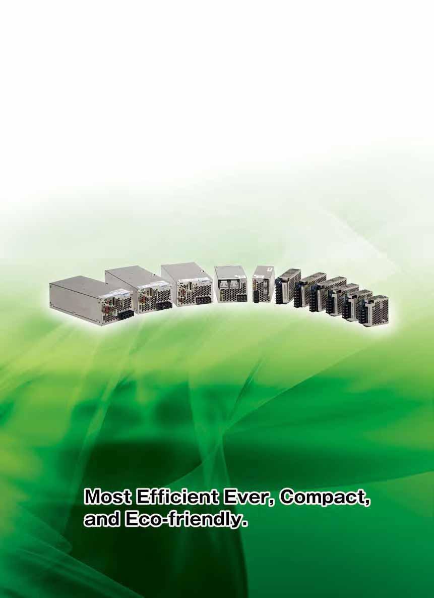
2 HWSSeries WIDE SELECTION OF LINE UP RANGE FROM GENERAL INDUSTRIAL, MEDICAL, HEAVY DUTY TO POWER SUPPLY WITH PEAK OUTPUT HWS Series put together the concept of "Environment-friendly", "User-friendly", and "Safety" as its foundation to offer wide range of product. Environmental-friendly Green power line Complies with RoHS Directive Energy Saving HWS User-friendly Miniature package Unified style Extensive product line High reliability design Safety-oriented design Safe to operate HWS Series Line Up HWSGeneral industrial HWS/MEMedical standard (IEC60601) compliance HWS/HDSuitable for harsh environment/heavy duty equipment HWS-PPeak power load HWS Series Model Name HWS- Option code Output voltage Output power Output power In addition to 11 models for 15W 1800W, there are 2 models for peak power models which bring the total of 13 models. Output voltage Wide variety of line up from 3.3V to 48V. 60V is also available for 1000W and above models. Option code Code ME HD A R ADIN PV FG Contents EN/UL60601 Approved, low leakage current for medical application Double-sided coating and -40start up, suitable for harsh environment Cover for additional safety operation Remote ON/OFF by external voltage DIN Reel type External voltage adjustment Low leakage current type Not all models are available for above option and longer delivery might be needed for option models. Please contact our sales for more information
 90 85 HWS150 80 75 70 Previous model of 150W 65 60 3.")


3 HWSSeries AC/DC Switching Power Supply HWS Line up P7 Environment-friendly Complies to RoHS Directives Energy saving Reducing power loss during operation through high efficient design. Fan will stop during output "OFF" initiated by remote ON/OFF. Previous model Saves 19W HWS 150W Efficiency (%) HWS Previous model of 150W Output voltage User-friendly Exhaust type forced air cooling using built-in fans installed at the rear of the unit (300W W ) No space is required at the side between power supplies when multiple units are used. Built-in automated speed control fan contribute to low acoustic noise during normal temperature operation. Miniature Package By increasing efficiency and optimization of componets and circuit design, we achieved over 50% miniaturization. Miniaturization of over 50% 150W 42±1 Previous model 1500W 126.5±1 Previous model Unified style Unified style of 82mm height make it more convenient in design when multiple units are used. All models can be embedded in 19-inch 2U rack mount Fit in 19-inch 2U rack mount H82mm Safety Reliability design Safety design Long Life 105 long life elec. capacitors are used and design to operate for 24 hours/365 days continously using guranteed life time from component manufacturers. High efficiency design Synchronous rectification circuit is used in 3.3V/5V output to support lower voltage higher current. These products achieved more than 80% efficiency Warranty: 5 years Designed to meet worldwide safety regulation. It also meet the requirement for CE marking, which is a safety standard in European Union. UL508/CSA C22.2 No.14-M95 UL /CSA C22.2 No EN50178 Safety terminal Previously, cover was required to ensure safety in the terminal. With safety terminal, life areas are covered by terminal block and direct contact with finger can be prevented (finger protection). With integral construction between screw and terminal, it will prevent the screw from dropping off into the unit (300W 1800W type are using input terminal) Live area, terminal screw are covered. Safety terminal does not require terminal cover Terminal are tightened with screwdriver. Screw cannot fall out or loss Terminal structure with integrated screw inserting round crimp terminal safety is assured even without terminal cover HWS featured red marking on the + side and black marking on the - of the output terminal. This reduce the possibility of incorrect connection Safe operation While swicthing power supply provide stable DC power, there are environmental condition requirement that unique to the different fields in which equipment is used. The momentary voltage drop (voltage sag) power supply fault that may occur due to certain natural disaster or lightning is a critical issue for semiconductor factories and semiconductor manufacturing equipment. The supply voltage sag (voltage drop) and duration is stipulated by the SEMIF , " Specification For Semiconductor Processing Equipment Voltage Sag Immunity" standard which is a US semicondutor equipment standard and can be met when 200VAC input is used.
4 HWSSeries HWS/ME AC/DC Switching power supply for medical application Era where standard power supply used in medical application Line up P51 Medical safety standard (EN60601/UL60601) compliance Contribute to shortened the time needed in developing medical equipment and reduce its cost 7 models with 42 line ups Main applications Medical lasers, X-Ray, Microwave theraphy equipment Diagnosis equipments, Analysis/testing devices Leakage current: max. 0.5mA EMC Immunity (All models) Items Electrostatic Radiated susceptibility Electrical fast transient/burst Surge Conducted susceptibility Power frequency magnetic field Voltage dips. Short interuption Standard lec lec lec lec lec lec lec Compliance Level Level3 (Level 2,3 for 300W, 600W) Level 3 Level 3 Level 3,4 Level 3 Level 4 Complied Notes Aerial discharge: 8kV Contact discharge:6kv (4kV for 1500W) 10V/m 2kV Common: 4.0kV Differential mode: 2.0kV 10V 30A/m Emission (HWS30,50,100,150,300/ME) Emission (HWS 600,1500/ME) Test items Standard Notes Test items Standard Notes Radiated electric field EN55022/EN55011,FCC,VCCI Class B Compliance Radiated electric field EN55022/EN55011,FCC,VCCI Class A Compliance Conducted emissions EN55022/EN55011,FCC,VCCI Class B Compliance Conducted emissions EN55022/EN55011,FCC,VCCI Class A Compliance Conducted harmonics IEC Conformed Conducted harmonics IEC Conformed Flicker IEC Conformed Flicker IEC Conformed Attention: Please read the instruction manual carefully before using this product. On top of the following condition, please refer to to "HWS Series" standard instruction manual (p25-). Please confirm whether there is insulation materials used inside the equipment (whether there is patient direct contact or indirect contact with the equipment). All models are approved for basic insulation, therefore additional insulation circuit may be needed in the equipment. HWS/HD AC/DC Standard switching power supply for rugged and heavy duty Harsh environment applications Line up P31-40 Start up Main applications PCB coating Designed to meet MIL-STD-810F (shock and vibration) LED display Device Process control Factory machinery

5 HWSSeries AC/DC Switching power supply with peak power capability Support drive load with 3 times of peak power Line up P69 Up to 3 times of peak current Main applications High power in compact size Low acoustic noise with automated speed control fan Factory machiney Semiconductor testing device Textile machinery, Cash dispenser Up to 3 times peak current to give powerful support to motor and printer head application High Reliability and User Friendly Power Supply for Drive Load Application The growth of motor and printer head applications, the center of multifunction and high speed machineries, have been increased from year to year. HWS-P is superior to provide function to support instant current in typical drive load with up to 3 times peak current in compact size. By taking into consideration on the demand of high reliability industrial equipment, elec. capacitor is expected to have 7 year of life (Ta=40. Also, 5 year warranty is provided. The design include OCP circuit with shut off function, OVP circuit, temperature sensor for automatic speed control fan as well as built-in OTP circuit. All of these functions give a better safety and ease to the users. Output Voltage Mode Ave. output current HWS300P HWS600P Peak current Ave. output Peak current 100V input 200V input current 100V input 200V input 24V 12.5A 21.0A 42.0A 25.0A 40.5A 83.0A 36V 8.4A 14.0A 28.0A 16.7A 27.0A 55.5A 48V 6.3A 10.5A 21.0A 12.5A 20.0A 41.5A
6 HWS Specifications HWS15 8 HWS30 10 HWS50 12 HWS80 14 HWS HWS HWS HWS HWS HWS HWS1800T 28 HWS/HD 31 Contents Specifications HWS30/HD 32 HWS50/HD 34 HWS100/HD 36 HWS150/HD 38 HWS300/HD 40 HWS600/HD 42 HWS1000/HD 44 HWS1500/HD 46 HWS1800T/HD 48 HWS/ME 51 Specifications HWS30/ME 52 HWS50/ME 54 HWS100/ME 56 HWS150/ME 58 HWS300/ME 60 HWS600/ME 62 HWS1000/ME 64 HWS1500/ME 66 HWS-P 69 Specifications HWS300P 70 HWS600P 72 HWS Series All 74 Block Diagram HWS15, 30, 50, 80, 100, HWS300, 600, HWS1500, 1800T 76 Sequence Time Chart HWS300, 600, HWS1500, 1800T 78 HWS15, 30, 50, 80, 100, HWS300, HWS HWS HWS1800T 113 HWS300P, 600P 124 7

7 HWS 5
8 HWS 15 HWS15 Specifications(Read instruction manual carefully, before using the power supply unit.) ITEMS/UNITS MODEL HWS15-3 HWS15-5 HWS15-12 HWS15-15 HWS15-24 HWS15-48 Voltage Range (*2) V AC or DC Frequency (*2) Hz Input Efficiency (100/200VAC)(typ) (*1) 68 / / / / / 80 Current (100/200VAC)(typ) (*1) A 0.3 / / 0.2 Inrush Current (100/200VAC)(typ) (*3) A 14 / 28, Ta=25, cold start Leakage Current (*10) ma Less than 0.5. (0.2 (typ) at 100VAC / 0.4 (typ) at 230VAC) Nominal Voltage VDC Maximum Current A Maximum Power W Maximum Line Regulation (*5) mv Output Maximum Load Regulation (*6) mv Temperature Coefficient Less than 0.02% / Maximum Ripple & Noise (0<Ta<70) (*4) mvp-p Maximum Ripple & Noise (10<Ta<0) (*4) mvp-p Hold-up Time (typ) (*9) ms 20 Voltage Adjustable Range VDC Over Current Protection (*7) A >3.15 >1.36 >1.05 >0.68 >0.34 Over Voltage Protection (*8) VDC Remote Sensing - Function Remote ON/OFF Control - Parallel Operation - Series Operation Line DIP Built to meet SEMI-F47 (200VAC Line only) Operating Temperature (*11) -10 to +70 (-10 to +50: 100%, +60: 60%, +70: 20%) Storage Temperature -30 to +85 Operating Humidity RH (No dewdrop) Storage Humidity RH (No dewdrop) Environment At no operating, 10-55Hz (sweep for 1min) Vibration 19.6m/s² constant, X, Y, Z 1hour each. Shock (In package) Less than 196.1m/s² Cooling Convection cooling Input - FG : 2kVAC (20mA), Input - Output : 3kVAC (20mA) Withstand Voltage Isolation Output - FG : 500VAC (100mA) for 1min Isolation Resistance More than 100M at 25 and 70%RH Output - FG : 500VDC Safety Standards (*12) Approved by UL , CSA C22.2 No , EN , EN50178 UL508 (with cover models only), CSA C22.2 No.14-M95 (with cover models only) Built to meet UL508, DENAN PFHC Built to meet IEC Standards EMI Built to meet EN55011/EN55022-B, FCC-B, VCCI-B Immunity Built to meet IEC (Level 2,3), -3(Level 3), -4(Level 3), -5(Level 3,4), -6(Level 3), -8(Level 4), -11 Weight (typ) g 180 Mechanical Size (W x H x D) mm 26.5 x 82 x 80 (Refer to outline drawing) (*1) At 100/200VAC, Ta=25 and maximum output power. (*2) For cases where conformance to various safety specs (UL, CSA, EN) are required, to be described as VAC (50/60Hz). (*3) Not applicable for the in-rush current to noise filter for less than 0.2ms. (*4) Measure with JEITA RC-9131A probe, bandwidth of scope :100MHz. For start up at low ambient temperature and low input voltage, output ripple noise might not meet specification. However, there is no overshoot at start up and output ripple noise specification can be met after one second. (*5) VAC, constant load. (*6) No load-full load, constant input voltage. (*7) Foldback current limit with automatic recovery. Not operate at over load or dead short condition for more than 30 seconds. (*8) OVP circuit will shutdown output, manual reset (Re power on). (*9) At 100/200VAC, Ta=25, nominal output voltage and maximum output current. (*10) Measured by the each measuring method of UL, CSA, EN and DENAN (at 60Hz). (*11) Ratings - Derating at standard mounting. - Load (%) is percent of maximum output power or maximum output current, whichever is greater. - As for other mountings, refer to derating curve. (*12) As for DENAN, built to meet at 100VAC.
9 HWS 15 Outline Drawing Output Derating
10 HWS 30 HWS30 Specifications(Read instruction manual carefully, before using the power supply unit.) ITEMS/UNITS MODEL HWS30-3 HWS30-5 HWS30-12 HWS30-15 HWS30-24 HWS30-48 Voltage Range (*2) V AC or DC Frequency (*2) Hz Input Efficiency (100/200VAC)(typ) (*1) 70 / / / / / 83 Current (100/200VAC)(typ) (*1) A 0.6 / / 0.4 Inrush Current (100/200VAC)(typ) (*3) A 14 / 28, Ta=25, cold start Leakage Current (*10) ma Less than 0.5. (0.2 (typ) at 100VAC / 0.4 (typ) at 230VAC) Nominal Voltage VDC Maximum Current A Maximum Power W Maximum Line Regulation (*5) mv Output Maximum Load Regulation (*6) mv Temperature Coefficient Less than 0.02% / Maximum Ripple & Noise (0 Ta 70) (*4) mvp-p Maximum Ripple & Noise (10 Ta< 0) (*4) mvp-p Hold-up Time (typ) (*9) ms 20 Voltage Adjustable Range VDC Over Current Protection (*7) A >6.3 >2.62 >2.1 >1.36 >0.68 Over Voltage Protection (*8) VDC Remote Sensing - Function Remote ON/OFF Control - Parallel Operation - Series Operation Line DIP Built to meet SEMI-F47 (200VAC Line only) Operating Temperature (*11) -10 to +70 (-10 to +50: 100%, +60: 60%, +70: 20%) Storage Temperature -30 to +85 Operating Humidity RH (No dewdrop) Storage Humidity RH (No dewdrop) Environment At no operating, 10-55Hz (sweep for 1min) Vibration 19.6m/s² constant, X, Y, Z 1hour each. Shock (In package) Less than 196.1m/s² Cooling Convection cooling Input - FG : 2kVAC (20mA), Input - Output : 3kVAC (20mA) Withstand Voltage Isolation Output - FG : 500VAC (100mA) for 1min Isolation Resistance More than 100M at 25 and 70%RH Output - FG : 500VDC Safety Standards (*12) Approved by UL , CSA C22.2 No , EN , EN50178 UL508 (with cover models only), CSA C22.2 No.14-M95 (with cover models only) Built to meet DENAN PFHC Built to meet IEC Standards EMI Built to meet EN55011/EN55022-B, FCC-B, VCCI-B Immunity Built to meet IEC (Level 2,3), -3(Level 3), -4(Level 3), -5(Level 3,4), -6(Level 3), -8(Level 4), -11 Weight (typ) g 220 Mechanical Size (W x H x D) mm 26.5 x 82 x 95 (Refer to outline drawing) (*1) At 100/200VAC, Ta=25 and maximum output power. (*2) For cases where conformance to various safety specs (UL, CSA, EN) are required, to be described as VAC (50/60Hz). (*3) Not applicable for the in-rush current to noise filter for less than 0.2ms. (*4) Measure with JEITA RC-9131A probe, bandwidth of scope :100MHz. For start up at low ambient temperature and low input voltage, output ripple noise might not meet specification. However, there is no overshoot at start up and output ripple noise specification can be met after one second. (*5) VAC, constant load. (*6) No load-full load, constant input voltage. (*7) Foldback current limit with automatic recovery. Not operate at over load or dead short condition for more than 30 seconds. (*8) OVP circuit will shutdown output, manual reset (re power on). (*9) At 100/200VAC, Ta=25, nominal output voltage and maximum output current. (*10) Measured by the each measuring method of UL, CSA, EN and DENAN (at 60Hz). (*11) Ratings - Derating at standard mounting. - Load (%) is percent of maximum output power or maximum output current, whichever is greater. - As for other mountings, refer to derating curve. (*12) As for DENAN, built to meet at 100VAC.
11 HWS 30 Outline Drawing Output Derating
12 HWS 50 HWS50 Specifications(Read instruction manual carefully, before using the power supply unit.) ITEMS/UNITS MODEL HWS50-3 HWS50-5 HWS50-12 HWS50-15 HWS50-24 HWS50-48 Voltage Range (*2) V AC or DC Frequency (*2) Hz Power Factor (100/200VAC)(typ) (*1) 0.98 / / 0.95 Input Efficiency (100/200VAC)(typ) (*1) 76 / / / / / 85 Current (100/200VAC)(typ) (*1) A 0.5 / / 0.35 Inrush Current (100/200VAC)(typ) (*3) A 14 / 28, Ta=25, cold start Leakage Current (*10) ma Less than 0.5. (0.2 (typ) at 100VAC / 0.4 (typ) at 230VAC) Nominal Voltage V Maximum Current A Maximum Power W Maximum Line Regulation (*5) mv Output Maximum Load Regulation (*6) mv Temperature Coefficient Less than 0.02% / Maximum Ripple & Noise (0 Ta 70) (*4) mvp-p Maximum Ripple & Noise (10 Ta< 0) (*4) mvp-p Hold-up Time (typ) (*9) ms 20 Voltage Adjustable Range VDC Over Current Protection (*7) A >10.5 >4.51 >3.67 >2.31 >1.15 Over Voltage Protection (*8) V Remote Sensing - Function Remote ON/OFF Control (/R Option) Parallel Operation - Series Operation Line DIP Built to meet SEMI-F47 (200VAC Line only) Operating Temperature (*11) -10 to +70 (-10 to +50: 100%, +60: 60%, +70: 20%) Storage Temperature -30 to +85 Operating Humidity RH (No dewdrop) Storage Humidity RH (No dewdrop) Environment At no operating, 10-55Hz (sweep for 1min) 19.6m/s² constant, Vibration X, Y, Z 1hour each. Shock (In package) Less than 196.1m/s² Cooling Convection cooling Input - FG : 2kVAC (20mA), Input - Output : 3kVAC (20mA) Withstand Voltage Isolation Output - FG : 500VAC (100mA) for 1min Isolation Resistance More than 100M at 25 and 70%RH Output - FG : 500VDC Safety Standards (*12) Approved by UL , CSA C22.2 No , EN , EN50178 UL508 (with cover models only), CSA C22.2 No.14-M95 (with cover models only) Built to meet DENAN PFHC Built to meet IEC Standards EMI Built to meet EN55011/EN55022-B, FCC-B, VCCI-B Immunity Built to meet IEC (Level 2,3), -3(Level 3), -4(Level 3), - 5(Level 3,4), -6(Level 3), -8(Level 4), -11 Weight (typ) g 280 Mechanical Size (W x H x D) mm 26.5 x 82 x 120 (Refer to outline drawing) (*1) At 100/200VAC, Ta=25 and maximum output power. (*2) For cases where conformance to various safety specs (UL, CSA, EN) are required, to be described as VAC (50/60Hz). (*3) Not applicable for the in-rush current to noise filter for less than 0.2ms. (*4) Measure with JEITA RC-9131A probe, bandwidth of scope : 100MHz. (*5) VAC, constant load. (*6) No load-full load, constant input voltage. (*7) Constant current limit and hiccup with automatic recovery. Not operate at over load or dead short condition for more than 30 seconds. (*8) OVP circuit will shutdown output, manual reset (re power on). (*9) At 100/200VAC, nominal output voltage and maximum output current. (*10) Measured by the each measuring method of UL, CSA, EN and DENAN (at 60Hz). (*11) Ratings - Derating at standard mounting. - Load (%) is percent of maximum output power or maximum output current, whichever is greater. - As for other mountings, refer to derating curve. (*12) As for DENAN, built to meet at 100VAC.
13 HWS 50 Outline Drawing Output Derating
14 HWS 80 HWS80 Specifications(Read instruction manual carefully, before using the power supply unit.) ITEMS/UNITS MODEL HWS80-3 HWS80-5 HWS80-12 HWS80-15 HWS80-24 HWS80-48 Voltage Range (*2) V AC or DC Frequency (*2) Hz Power Factor (100/200VAC)(typ) (*1) 0.98 / / 0.95 Input Efficiency (100/200VAC)(typ) (*1) 77 / / / / 86 Current (100/200VAC)(typ) (*1) A 0.72 / / 0.52 Inrush Current (100/200VAC)(typ) (*3) A 14 / 28, Ta=25, cold start Leakage Current (*10) ma Less than 0.5. (0.2 (typ) at 100VAC / 0.4 (typ) at 230VAC) Nominal Voltage VDC Maximum Current A Maximum Power W Maximum Line Regulation (*5) mv Output Maximum Load Regulation (*6) mv Temperature Coefficient Less than 0.02% / Maximum Ripple & Noise (0 Ta 70) (*4) mvp-p Maximum Ripple & Noise (10 Ta< 0) (*4) mvp-p Hold-up Time (typ) (*9) ms 20ms Voltage Adjustable Range VDC Over Current Protection (*7) A >16.8 >7.04 >5.67 >3.57 >1.79 Over Voltage Protection (*8) VDC Remote Sensing Function Remote ON/OFF Control (/R Option) Parallel Operation - Series Operation Line DIP Built to meet SEMI-F47 (200VAC Line only) Operating Temperature (*11) -10 to +70 (-10 to +50: 100%, +60: 60%, +70: 20%) Storage Temperature -30 to +85 Operating Humidity RH (No dewdrop) Storage Humidity RH (No dewdrop) Environment At no operating, 10-55Hz (sweep for 1min) Vibration 19.6m/s² constant, X, Y, Z 1hour each. Shock (In package) Less than 196.1m/s² Cooling Convection cooling Input - FG : 2kVAC (20mA), Input - Output : 3kVAC (20mA) Withstand Voltage Isolation Output - FG : 500VAC (100mA) for 1min Isolation Resistance More than 100M at 25 and 70%RH Output - FG : 500VDC Safety Standards (*12) Approved by UL , CSA C22.2 No , EN , EN50178 UL508 (with cover models only), CSA C22.2 No.14-M95 (with cover models only) Built to meet DENAN PFHC Built to meet IEC Standards EMI Built to meet EN55011/EN55022-B, FCC-B, VCCI-B Immunity Built to meet IEC (Level 2,3), -3(Level 3), -4(Level 3), -5(Level 3,4), -6(Level 3), -8(Level 4), -11 Weight (typ) g 450 Mechanical Size (W x H x D) mm 28 x 82 x 160 (Refer to outline drawing) (*1) At 100/200VAC, Ta=25 and maximum output power. (*2) For cases where conformance to various safety specs (UL, CSA, EN) are required, to be described as VAC (50/60Hz). (*3) Not applicable for the in-rush current to noise filter for less than 0.2ms. (*4) Measure with JEITA RC-9131A probe, bandwidth of scope : 100MHz. (*5) VAC, constant load. (*6) No load-full load, constant input voltage. (*7) Constant current limit and hiccup with automatic recovery. Not operate at over load or dead short condition for more than 30 seconds. (*8) OVP circuit will shutdown output, manual reset (re power on). (*9) At 100/200VAC, nominal output voltage and maximum output current. (*10) Measured by the each measuring method of UL, CSA, EN and DENAN (at 60Hz). (*11) Ratings - Derating at standard mounting. - Load (%) is percent of maximum output power or maximum output current, whichever is greater. - As for other mountings, refer to derating curve. (*12) As for DENAN, built to meet at 100VAC.
15 HWS 80 Outline Drawing Output Derating
16 HWS 100 HWS100 Specifications(Read instruction manual carefully, before using the power supply unit.) ITEMS/UNITS MODEL HWS100-3 HWS100-5 HWS HWS HWS HWS Voltage Range (*2) V AC or DC Frequency (*2) Hz Power Factor (100/200VAC)(typ) (*1) 0.98 / / 0.95 Input Efficiency (100/200VAC)(typ) (*1) 78 / / / 87 Current (100/200VAC)(typ) (*1) A 0.9 / / 0.65 Inrush Current (100/200VAC)(typ) (*3) A 14 / 28, Ta=25, cold start Leakage Current (*10) ma Less than 0.5. (0.2 (typ) at 100VAC / 0.4 (typ) at 230VAC) Nominal Voltage VDC Maximum Current A Maximum Power W Maximum Line Regulation (*5) mv Output Maximum Load Regulation (*6) mv Temperature Coefficient Less than 0.02% / Maximum Ripple & Noise (0 Ta 70)(*4) mvp-p Maximum Ripple & Noise (10 Ta< 0) (*4) mvp-p Hold-up Time (typ) (*9) ms 20 Voltage Adjustable Range VDC Over Current Protection (*7) A >21.0 >8.92 >7.35 >4.72 >2.20 Over Voltage Protection (*8) VDC Remote Sensing Function Remote ON/OFF Control (/R Option) Parallel Operation - Series Operation Line DIP Built to meet SEMI-F47 (200VAC Line only) Operating Temperature (*11) -10 to +70 (-10 to +50: 100%, +60: 60%, +70: 20%) Storage Temperature -30 to +85 Operating Humidity RH (No dewdrop) Storage Humidity RH (No dewdrop) Environment At no operating, 10-55Hz (sweep for 1min) 19.6m/s² constant, Vibration X, Y, Z 1hour each. Shock (In package) Less than 196.1m/s² Cooling Convection cooling Input - FG : 2kVAC (20mA), Input - Output : 3kVAC (20mA) Withstand Voltage Isolation Output - FG : 500VAC (100mA) for 1min Isolation Resistance More than 100M at 25 and 70%RH Output - FG : 500VDC Safety Standards (*12) Approved by UL , CSA C22.2 No , EN , EN50178 UL508 (with cover models only), CSA C22.2 No.14-M95 (with cover models only) Built to meet, DENAN PFHC Built to meet IEC Standards EMI Built to meet EN55011/EN55022-B, FCC-B, VCCI-B Immunity Built to meet IEC (Level 2,3), -3(Level 3), -4(Level 3), -5(Level 3,4), -6(Level 3), -8(Level 4), -11 Weight (typ) g 450 Mechanical Size (W x H x D) mm 28 x 82 x 160 (Refer to outline drawing) (*1) At 100/200VAC, Ta=25 and maximum output power. (*2) For cases where conformance to various safety specs (UL, CSA, EN) are required, to be described as VAC (50/60Hz). (*3) Not applicable for the in-rush current to noise filter for less than 0.2ms. (*4) Measure with JEITA RC-9131A probe, bandwidth of scope :100MHz. (*5) VAC, constant load. (*6) No load-full load, constant input voltage. (*7) Constant current limit and hiccup with automatic recovery. Not operate at over load or dead short condition for more than 30 seconds. (*8) OVP circuit will shutdown output, manual reset (re power on). (*9) At 100/200VAC, nominal output voltage and maximum output current. (*10) Measured by the each measuring method of UL, CSA, EN and DENAN (at 60Hz). (*11) Ratings - Derating at standard mounting. - Load (%) is percent of maximum output power or maximum output current, whichever is greater. - As for other mountings, refer to derating curve (*12) As for DENAN, built to meet at 100VAC.
17 HWS 100 Outline Drawing Output Derating
18 HWS 150 HWS150 Specifications(Read instruction manual carefully, before using the power supply unit.) ITEMS/UNITS MODEL HWS150-3 HWS150-5 HWS HWS HWS HWS Voltage Range (*2) V AC or DC Frequency (*2) Hz Power Factor (100/200VAC)(typ) (*1) 0.98 / / 0.95 Input Efficiency (100/200VAC)(typ) (*1) 78 / / / 88 Current (100/200VAC)(typ) (*1) A 1.3 / / 0.95 Inrush Current (100/200VAC)(typ) (*3) A 14 / 28, Ta=25, cold start Leakage Current (*10) ma Less than 0.5. (0.2 (typ) at 100VAC / 0.4 (typ) at 230VAC) Nominal Voltage V Maximum Current A Maximum Power W Maximum Line Regulation (*5) mv Output Maximum Load Regulation (*6) mv Temperature Coefficient Less than 0.02% / Maximum Ripple & Noise (0 Ta 70) (*4) mvp-p Maximum Ripple & Noise (10 Ta< 0) (*4) mvp-p Hold-up Time (typ) (*9) ms 20 Voltage Adjustable Range VDC Over Current Protection (*7) A >31.5 >13.6 >10.5 >6.82 >3.46 Over Voltage Protection (*8) V Remote Sensing (*8) Function Remote ON/OFF Control (/R Option) Parallel Operation - Series Operation Line DIP Built to meet SEMI-F47 (200VAC Line only) Operating Temperature (*11) -10 to +70 (-10 to +50: 100%, +60: 60%, +70: 20%) Storage Temperature -30 to +85 Operating Humidity RH (No dewdrop) Storage Humidity RH (No dewdrop) Environment At no operating, 10-55Hz (sweep for 1min) 19.6m/s² constant, Vibration X, Y, Z 1hour each. Shock (In package) Less than 196.1m/s² Cooling Convection cooling Input - FG : 2kVAC (20mA), Input - Output : 3kVAC (20mA) Withstand Voltage Isolation Output - FG : 500VAC (100mA) for 1min Isolation Resistance More than 100M at 25 and 70%RH Output - FG : 500VDC Safety Standards (*12) Approved by UL , CSA C22.2 No , EN , EN50178 UL508 (with cover models only), CSA C22.2 No.14-M95 (with cover models only)built to meet DENAN PFHC Built to meet IEC Standards EMI Built to meet EN55011/EN55022-B, FCC-B, VCCI-B Immunity Built to meet IEC (Level 2,3), -3(Level 3), -4(Level 3), -5(Level 3,4), -6(Level 3), -8(Level 4), -11 Weight (typ) g 500 Mechanical Size (W x H x D) mm 37 x 82 x 160 (Refer to outline drawing) (*1) At 100/200VAC, Ta=25 and maximum output power. (*2) For cases where conformance to various safety specs (UL, CSA, EN) are required, to be described as VAC (50/60Hz). (*3) Not applicable for the in-rush current to noise filter for less than 0.2ms. (*4) Measure with JEITA RC-9131A probe, bandwidth of scope : 100MHz. (*5) VAC, constant load. (*6) No load-full load, constant input voltage. (*7) Constant current limit and hiccup with automatic recovery. Not operate at over load or dead short condition for more than 30 seconds. (*8) OVP circuit will shutdown output, manual reset (re power on). (*9) At 100/200VAC, nominal output voltage and maximum output current. (*10) Measured by the each measuring method of UL, CSA, EN and DENAN (at 60Hz). (*11) Ratings - Derating at standard mounting. - Load (%) is percent of maximum output power or maximum output current, whichever is greater. - As for other mountings, refer to derating curve. (*12) As for DENAN, built to meet at 100VAC.
19 HWS 150 Outline Drawing Output Derating
20 HWS 300 HWS300 Specifications(Read instruction manual carefully, before using the power supply unit.) ITEMS/UNITS MODEL HWS300-3 HWS300-5 HWS HWS HWS HWS Voltage Range (*2) V AC or DC Frequency (*2) Hz Power Factor (100/200VAC)(typ) (*1) 0.99 / 0.95 Input Efficiency (100/200VAC)(typ) (*1) 74 / / / / 85 Current (100/200VAC)(typ) (*1) A 2.7 / / / 2.1 Inrush Current (100/200VAC)(typ) (*3) A 20 / 40 Leakage Current (*10) ma Less than (0.2 (typ) at 100VAC / 0.44 (typ) at 230VAC) Nominal Voltage VDC Maximum Current (*13) A (16.5) 7 Maximum Power W Maximum Line Regulation (*5) mv Output Maximum Load Regulation (*6) mv Temperature Coefficient Less than 0.02% / Maximum Ripple & Noise (0 Ta 70) (*4) mvp-p Maximum Ripple & Noise (10 Ta< 0) (*4) mvp-p Hold-up Time (typ) (*9) ms 20 Voltage Adjustable Range VDC Over Current Protection (*7) A >63 > 28.4 >23.1 >16.7 >7.4 Over Voltage Protection (*8) V Remote Sensing Remote ON/OFF Control Function Parallel Operation Series Operation Monitoring Signal PF (Open collector output) Line DIP Designed to meet SEMI-F47 (200VAC Line only) Operating Temperature (*11) -10 to +70 (-10 to +50: 100%, +70: 50%) Storage Temperature -30 to +85 Operating Humidity RH (No dewdrop) Storage Humidity RH (No dewdrop) Environment At no operating, 10-55Hz (sweep for 1min) 19.6m/s² constant, Vibration X, Y, Z 1hour each. Shock (In package) Less than 196.1m/s² Cooling Forced air by blower fan Withstand Voltage Isolation Isolation Resistance Input - FG : 2.5kVAC (20mA), Input - Output : 3kVAC (20mA) Output - FG: 500VAC (100mA), Output-CNT: 100VAC(100mA) for 1min More than 100M Output - FG : 500VDC More than 10M Output -CNT : 100VDC at 25 and 70%RH Approved by UL , UL508 (24V model only), CSA C22.2 No , Safety Standards (*12) CSA C22.2 No.14-M95 (24V model only), EN , EN50178 Designed to meet DENAN PFHC Designed to meet IEC Standards EMI Designed to meet EN55011/EN55022-B, FCC-B, VCCI-B Designed to meet IEC (Level 2,3), -3(Level 3), -4(Level3), Immunity -5(Level 3,4), -6(Level 3), -8(Level 4), -11 Weight (typ) g 1000 Mechanical Size (W x H x D) mm 61 x 82 x 165 (Refer to outline drawing) (*1) At 100/200VAC, Ta=25 and maximum output power. (*2) For cases where conformance to various safety specs (UL, CSA, EN) are required, to be described as VAC (50/60Hz). (*3) Not applicable for the inrush current to noise filter for less than 0.2ms. (*4) Measure with JEITA RC-9131A probe, bandwidth of scope :100MHz. (*5) VAC, constant load. (*6) No load-full load, constant input voltage. (*7) 3.3, 5V model: Constant current limit and hiccup with automatic recovery V model: Constant current limit with automatic recovery. Avoid to operate at over load or short circuit condition for more than 30 seconds. (*8) OVP circuit will shut the output down, manual reset (CNT reset or Re power on). (*9) At 100/200VAC, nominal output voltage and maximum output current. (*10) Measured by the each measuring method of UL, CSA, EN and DENAN (at 60Hz), Ta=25. (*11) Ratings - Derating at standard mounting. Refer to output derating curve. - Load (%) is percent of maximum output power or maximum output current, whichever is greater. (*12) As for DENAN, designed to meet at 100VAC. (*13) ( ): Peak output current at 200VAC. Operaing time at peak output is less than 10 sec, duty is less than 35%.
21 HWS 300 Outline Drawing Output Derating
22 HWS 600 HWS600 Specifications(Read instruction manual carefully, before using the power supply unit.) ITEMS/UNITS MODEL HWS600-3 HWS600-5 HWS HWS HWS HWS Voltage Range (*2) V AC or DC Frequency (*2) Hz Power Factor (100/200VAC)(typ) (*1) 0.99 / 0.95 Input Efficiency (100/200VAC)(typ) (*1) 75 / / / / / 86 Current (100/200VAC)(typ) (*1) A 5.4 / / / 3.9 Inrush Current (100/200VAC)(typ) (*3) A 20 / 40 Leakage Current (*10) ma Less than (0.2 (typ) at 100VAC / 0.44 (typ) at 230VAC) Nominal Voltage VDC Maximum Current (*13) A (31) 13 Maximum Power W Maximum Line Regulation (*5) mv Output Maximum Load Regulation (*6) mv Temperature Coefficient Less than 0.02 / Maximum Ripple & Noise (0 Ta 70) (*4) mvp-p Maximum Ripple & Noise (-10 Ta 0) (*4) mvp-p Hold-up Time (typ) (*9) ms 20ms Voltage Adjustable Range VDC Over Current Protection (*7) A >126 >55.7 >45.2 >31.4 >13.7 Over Voltage Protection (*8) VDC Remote Sensing Remote ON/OFF Control Function Parallel Operation Series Operation Monitoring Signal PF (Open collector output) Line DIP Designed to meet SEMI-F47 (200VAC Line only) Operating Temperature (*11) -10 to +70 (-10 to +50: 100, +70: 50) Storage Temperature -30 to +85 Operating Humidity RH (No dewdrop) Storage Humidity RH (No dewdrop) Environment At no operating, 10-55Hz (sweep for 1min) 19.6m/s² constant, Vibration X, Y, Z 1hour each. Shock (In package) Less than 196.1m/s² Cooling Forced air by blower fan Withstand Voltage Isolation Isolation Resistance Input - FG : 2.5kVAC (20mA), Input - Output : 3kVAC (20mA) Output - FG : 500VAC (100mA), Output - CNT : 100VAC (100mA) for 1min More than 100M Output - FG : 500VDC More than 10M Output - CNT: 100VDC at 25 and 70RH Approved by UL , UL508 (24V model only), CSA C22.2 No , Safety Standards (*12) CSA C22.2 No.14-M95 (24V model only), EN , EN50178,Designed to meet DENAN PFHC Designed to meet IEC Standards EMI Designed to meet EN55011/EN55022-B, FCC-B, VCCI-B Designed to meet IEC (Level 2,3), -3(Level 3), Immunity -4(Level 3), -5(Level 3,4), -6(Level 3), -8(Level 4), -11 Weight (typ) g 1600 Mechanical Size (W x H x D) mm 100 x 82 x 165 (Refer to outline drawing) (*1) At 100/200VAC, Ta=25 and maximum output power. (*2) For cases where conformance to various safety specs (UL, CSA, EN) are required, to be described as VAC (50/60Hz). (*3) Not applicable for the inrush current to noise filter for less than 0.2ms. Inrush current is 30A (typ) when PFHC start-up. (*4) Measure with JEITA RC-9131A probe, bandwidth of scope :100MHz. (*5) VAC, constant load. (*6) No load - full load, constant input voltage. (*7) 3V and 5V model: Constant current limit and hiccup with automatic recovery V model: Constant current limit with automatic recovery. Avoid to operate at over load or short circuit condition for more than 30 seconds. (*8) OVP circuit will shut the output down, manual reset (CNT reset or re-power on). (*9) At 100/200VAC, nominal output voltage and maximum output current. (*10) Measured by the each measuring method of UL, CSA, EN and DENAN (at 60Hz), Ta=25. (*11) Ratings - Derating at standard mounting. Refer to output derating curve. - Load (%) is percent of maximum output power or maximum output current, whichever is greater. (*12) As for DENAN, designed to meet at 100VAC. (*13) ( ): Peak output current at 200VAC. Operating time at peak output is less than 10 sec, duty is less than 35%.
23 HWS 600 Outline Drawing Output Derating
24 HWS 1000 HWS1000 Specifications(Read instruction manual carefully, before using the power supply unit.) ITEMS/UNITS Input Output MODEL Voltage Range (*2) V AC or DC Frequency (*2) Hz Power Factor (100/200VAC)(typ) (*1) 0.98 / 0.95 Efficiency (100/200VAC)(typ) (*1) 71 / / / / / / / / / / 88 Current (100/200VAC)(typ) (*1) A 9.6 / / 7.0 Inrush Current (100/200VAC)(typ) (*3) A 20 / 40 Leakage Current (100/240VAC) (*10) ma 1.2 max Nominal Voltage VDC Maximum Current A Maximum Peak Current (*13) A Maximum Power W Maximum Peak Power (*13) W Maximum Line Regulation (*5) mv Maximum Load Regulation (*6) mv Temperature Coefficient Less than 0.02%/ Maximum Ripple & Noise (*4) 0 to +71C mvp-p to 0C mvp-p Hold-up Time (typ) (*9) ms 20 Voltage Adjustable Range VDC Over Current Protection (*7) A >210.0 >175.3 >168.0 >105.0 >84.0 >61.4 >40.9 >30.6 >24.5 Over Voltage Protection (*8) VDC Remote Sensing Remote ON/OFF Control Function Parallel Operation Series Operation Monitoring Signal PF (Open collector output) Line DIP Built to meet SEMI-F47 (200VAC line only) Operating Temperature (*11) -10 to +71, start up -20 to to Storage Temperature -30 to +85 Environment Operating Humidity RH (No Condensing) Storage Humidity RH (No Condensing) Vibration At no operating, 10-55Hz (sweep for 1min.) 19.6m/s² constant, X, Y, Z 1hour each. Shock (In package) Less than 196.1m/s² Cooling Forced air by blower fan Withstand Voltage Isolation Isolation Resistance Input - FG : 2kVAC (20mA), Input - Output : 3kVAC (20mA) Output-FG : 500VAC (300mA) (60V model 651VAC (390mA)), Output-CNT:100VAC (100mA) for 1min. More than 100M Output - FG : 500VDC More than 10M Output - CNT 100VDC at 25 and 70%RH Safety Standards (*12) Approved by UL , CSA C22.2 No , EN ,EN Built to meet DENAN. PFHC Built to meet IEC Standards EMI Built to meet EN55011/EN55022-B, FCC-ClassB, VCCI-ClassB, CISPR-ClassB. Immunity Built to meet IEC (Level 2,3), -3(Level 3), -4(Level 3), -5(Level 3,4), -6(Level 3), -8(Level 4), -11 Weight (max) g 3200 Mechanical Size (W x H x D) mm x 82 x 240 (Refer to outline drawing) (*1) At Ta=25 and maximum output power. (*2) For cases where conformance to various safety specs (UL, CSA, EN) are required, input voltage range will be VAC (50/60Hz). (*3) First in-rush current. Not applicable to the first 0.2ms in-rush current flowing into the power supply noise filter. (*4) Measure with JEITA RC-9131A probe, bandwidth of scope :100MHz. At 100uF electric capacitor and 0.47uF film capacitor on the test fixture board.) (*5) VAC, constant load. (*6) No load-full load, constant input voltage. (*7) Constant current limit with automatic recovery. Over current condition for more than 5 seconds will cause the output to shutdown. Output current exceeding maximum rated output current for more then 10 seconds continuously will result to output shutdown. (*8) OVP circuit will shut down output, manual reset (power cycle) or ON/OFF CNT signal reset. (*9) At 100/200VAC, nominal output voltage and maximum output current. (*10) Measured by the each measuring method of UL, CSA, EN and DENAN (at 60Hz), Ta=25. (*11) Ratings - Derating at standard mounting. -Load (%) is percent of maximum output power or maximum output current, whichever is greater. -As for other mountings, refer to derating curve. (*12) As for DENAN, built to meet at 100VAC. (*13) Peak output current is less than 10 seconds, and duty 35% max.(200vac Line only)
25 HWS 1000 Outline Drawing Output Derating
26 HWS 1500 HWS1500 Specifications(Read instruction manual carefully, before using the power supply unit.) ITEMS/UNITS Input Output Function MODEL HWS HWS HWS HWS HWS HWS HWS HWS HWS HWS Voltage Range (*2) V AC or DC Frequency (*2) Hz Power Factor (100/230VAC)(typ) (*1) 0.98 / 0.94 Efficiency (100/200VAC)(typ) (*1) 72 / / / / / / / / 90 Current (100/200VAC)(typ) (*1) A 15.0 / / / 10.0 Inrush Current (100/200VAC)(typ) (*3) A 20 / 40 Leakage Current (100/240VAC) (*10) ma 1.5 max Nominal Voltage VDC Maximum Current (100/200VAC) A 300 / / / / / / / / / 28 Maximum Peak Current (*13) A Maximum Power (100/200VAC) W 990 / / / / / / 1680 Maximum Peak Power (*13) W Maximum Line Regulation (*5) mv Maximum Load Regulation (*6) mv Temperature Coefficient Less than 0.02%/ +25 to +70 mvp-p Maximum 0 mvp-p Ripple & Noise (*4) -10 mvp-p Hold-up Time (typ) (*9) ms Voltage Adjustable Range VDC Over Current Protection (*7) A >315.0 >262.5 >210.0 >131.2 >105.0 >68.2 >44.1 >33.6 >26.8 Over Voltage Protection (*8) VDC Remote Sensing Remote ON/OFF Control Parallel Operation Series Operation Monitoring Signal PF (Open collector output) Line DIP Built to meet SEMI-F47 (200VAC Line only) Operating Temperature (*11) -10 to +70, start up -20 to +70 at Input Voltage 100VAC/200VAC -10 to +40 C W / / / C W / / / C W / / / C W / / / 840 Environment Storage Temperature -30 to +85 Operating Humidity RH (No Condensing) Storage Humidity RH (No Condensing) Vibration At no operating, 10-55Hz (sweep for 1min.) 19.6m/s² constant, X, Y, Z 1hour each. Shock (In package) Less than 196.1m/s² Cooling Forced air by blower fan Input - FG : 2kVAC (20mA), Input - Output : 3kVAC (20mA), Output - CNT : 100VAC (100mA) Withstand Voltage Isolation Output - FG : 500VAC (300mA), (60V model 651VAC (390mA) ) for 1min. Isolation Resistance More than 100M Output - FG : 500VDC More than 10M Output - CNT 100VDC at 25 and 70%RH Safety Standards (*12) Approved by UL , CSA C22.2 No , EN , EN Built to meet DENAN. PFHC Built to meet IEC Standards EMI Built to meet EN55011/EN55022-A, FCC-ClassA, VCCI-ClassA. Immunity Built to meet IEC (Level 2,3), -3(Level 3), -4(Level 3), -5(Level 3,4), -6(Level 3), -8(Level 4), -11 Weight (typ) g Mechanical Size (W x H x D) mm x 82 x 280 (Refer to outline drawing) (*1) At Ta=25 and maximum output power. (*2) For cases where conformance to various safety specs (UL, CSA, EN) are required, input voltage range will be VAC (50/60Hz). (*3) First in-rush current. Not applicable to the first 0.2ms in-rush current flowing into the power supply noise filter. (*4) Measure with JEITA RC-9131A probe, bandwidth of scope: 100MHz. (at 100uF electric capacitor and 0.47uF film capacitor on the test fixture board.) Ripple noise spec for ambient temperature between -10 to 25 is a linearity value with respect to the -10 degrees C and 25 degrees C specs. (*5) VAC, constant load. (*6) No load-full load, constant input voltage. (*7) Constant current limit with automatic recovery. Over current condition for more than 5 seconds will cause the output to shutdown. Output current exceeding maximum rated output current for more then 10 seconds continuously will result to output shutdown. (*8) OVP circuit will shut down output, manual reset (power cycle) or ON/OFF CNT signal reset. (*9) At 100/200VAC, nominal output voltage and maximum output current. (*10) Measured by the each measuring method of UL, CSA, EN and DENAN (at 60Hz), Ta=25. (*11) Ratings - Derating at standard mounting. - Load (%) is percent of maximum output power or maximum output current, whichever is greater. - As for other mountings, refer to derating curve. (*12) As for DENAN, built to meet at 100VAC. (*13) Peak output current is less than 10 seconds, and duty 35% max. (200VAC Line only)
27 HWS 1500 Outline Drawing Output Derating
 ITEMS/UNITS Input Output MODEL Voltage Range (*2) V 3 AC170-265 Frequency (*2) Hz 47-63 Power Factor (200VAC)(typ) (*1) 0.")
28 HWS 1800T HWS1800T Specifications(Read instruction manual carefully, before using the power supply unit.) ITEMS/UNITS Input Output MODEL Voltage Range (*2) V 3 AC Frequency (*2) Hz Power Factor (200VAC)(typ) (*1) 0.94 Efficiency (200VAC)(typ) (*1) Current (200VAC)(typ) (*1) A Inrush Current (200VAC)(typ) (*3) A 40 Leakage Current (240VAC) (*10) ma 2.6 max Nominal Voltage VDC Maximum Current A Maximum Peak Current (*12) A Maximum Power W Maximum Peak Power (*12) W Maximum Line Regulation (*5) mv Maximum Load Regulation (*6) mv Temperature Coefficient Less than 0.02%/ Maximum Ripple & Noise +25 to +71 mvp-p mvp-p mvp-p (*4) Hold-up Time (typ) (*9) ms Voltage Adjustable Range VDC Over Current Protection (*7) A >315.0 >303.0 >242.4 >151.5 >121.2 >106.0 >70.7 >53.0 >42.4 Over Voltage Protection (*8) VDC Remote Sensing Remote ON/OFF Control Function Output Voltage External Control Parallel Operation Series Operation Monitoring Signal PF (Open collector output) Line DIP Built to meet SEMI-F47 Operating Temperature (*11) -10 to +71, Start up -20 to to +40 W W W W Environment Storage Temperature -30 to +85 Operating Humidity RH (No Condensing) Storage Humidity RH (No Condensing) Vibration At no operating, 10-55Hz (sweep for 1min.) 19.6m/s² constant, X, Y, Z 1hour each. Shock (In package) Less than 196.1m/s² Cooling Forced air by blower fan Withstand Voltage Isolation Isolation Resistance Safety Standards EMI Standards Immunity Mechanical Input - FG : 2kVAC (20mA), Input - Output : 3kVAC (20mA), Output-FG : 500VAC (300mA), (60V model 651VAC(390mA)), Output-CNT:100VAC (100mA) for 1min More than 100M Output - FG : 500VDC More than 10M Output - CNT 100VDC at 25 and 70%RH Approved by UL , CSA C22.2 No , EN Built to meet EN55011/EN55022-A, FCC-ClassA, VCCI-ClassA. Built to meet IEC (Level 2,3), -3(Level 3), -4(Level 3), -5(Level 3,4), -6(Level 3), -8(Level 4), -11 Weight (typ) g Size (W x H x D) mm x 82 x 280 (Refer to outline drawing) (*1) At Ta=25 and maximum output power. (*2) For cases where conformance to various safety specs (UL, CSA, EN) are required, input voltage range will be VAC (50/60Hz). (*3) First in-rush current. Not applicable to the first 0.2ms in-rush current flowing into the power supply noise filter. (*4) Measure with JEITA RC-9131A probe, bandwidth of scope: 100MHz. At 100uF electric capacitor and 0.47uF film capacitor on the test fixture board.) Ripple noise spec for ambient temperature between -10 to 25 is a linearity value with respect to the -10 degrees C and 25 degrees C specs. (*5) VAC, constant load. (*6) No load-full load, constant input voltage. (*7) Constant current limit with automatic recovery. Over current condition for more than 5 seconds will cause the output to shutdown. Output current exceeding maximum rated output current for more then 10 seconds continuously will result to output shutdown. (*8) OVP circuit will shut down output, manual reset (power cycle) or ON/OFF CNT signal reset. (*9) At 200VAC(50/60Hz), nominal output voltage and maximum output current. (*10) Measured by the each measuring method of UL, CSA and EN (at 60Hz), Ta=25. (*11) Ratings - Derating at standard mounting. - As for other mountings, refer to derating curve. (*12) Peak output current is less than 10 seconds, and duty 35% max.
29 HWS 1800T Outline Drawing FG L3 L2 L1 Output Derating
30

31 HWS/HD UL / CSA C22.2 No EN / EN
32 HWS30/HD HWS30/HD Specifications(Read instruction manual carefully, before using the power supply unit.) ITEMS/UNITS Input Output MODEL HWS30-3/HD HWS30-5/HD HWS30-12/HD HWS30-15/HD HWS30-24/HD HWS30-48/HD Voltage Range (*2) V AC or DC Frequency (*2) Hz Efficiency (100/200VAC)(typ) (*1) 70/73 77/80 81/83 83/86 82/83 Current (100/200VAC)(typ) (*1) A 0.6/ /0.4 Inrush Current (typ) (*3) A 14A at 100VAC, 28 at 200VAC, Ta=25C, Cold Start Leakage Current (*10) ma Less than 0.5m. (0.2(Typ) at 100VAC / 0.4mA(Typ) at 230VAC) Nominal Voltage VDC Maximum Current A Maximum Power W Maximum Line Regulation (*5) mv Maximum Load Regulation (*6) mv Temperature Coefficient Less than 0.02% / Maximum Ripple & Noise (0Ta71) (*4) mvp-p Maximum Ripple & Noise (-10Ta< 0) (*4) mvp-p Hold-up Time (typ) (*9) ms 20 Voltage Adjustable Range VDC Over Current Protection (*7) A >6.3 >2.62 >2.1 >1.36 >0.68 Over Voltage Protection (*8) VDC Function Remote Sensing - Parallel Operation - Series Operation Line DIP Designed to meet SEMI-F47 (200VAC Line only) Isolation Environment Standards Mechanical Operating Temperature (*11) -10 to +71 (-10 to +50:100%,+60:60%,+71:20%) Guarantee Start up at -40 to -10 Storage Temperature -40 to +85 Operating Humidity RH 30 to 90 (No dewdrop) Storage Humidity RH 10 to 95 (No dewdrop) Vibration (*12) Shock (In package) Cooling Withstand Voltage Isolation Resistance Safety Standards (*13) PFHC EMI Immunity At no operating, 10-55Hz (Sweep for 1min) 19.6m/s² Constant, X,Y,Z 1hour each. Designed to meet MIL-STD-810F Category 4, 10 Less than 196.1m/s² Designed to meet MIL-STD-810F Procedure I, VI Convection Cooling Input - FG : 2kVAC (20mA), Input - Output : 3kVAC (20mA) Output - FG : 500VAC (100mA) for 1min More than 100M at 25C and 70%RH Output - FG : 500VDC Approved by UL , CSA , EN , EN50178 Designed to meet UL508, DENAN Designed to meet IEC Designed to meet EN55011/EN55022-B, FCC-B, VCCI-B Designed to meet IEC (Level 2,3), -3(Level 3), -4(Level 3), -5(Level 3,4), -6(Level 3), -8(Level 4), -11 Weight (typ) g 220g Size (WHD) mm 26.5 x 82 x 95 ( Refer to Outline Drawing ) (*1) At 100/200VAC, Ta=25 C and maximum output power. (*2) For cases where conformance to various safety specs (UL, CSA, EN) are required, to be described as VAC(50/60Hz). (*3) Not applicable for the in-rush current to Noise Filter for less than 0.2ms. (*4) Measure with JEITA RC-9131A probe, Bandwidth of scope :100MHz. For start up at low ambient temperature and low input voltage, output ripple noise might not meet specification. However, there is no overshoot at start up and output ripple noise specification can be met after one second. (*5) VAC, constant load. (*6) No load-full load, constant input voltage. (*7) Foldback current limit with automatic recovery. Not operate at over load or dead short condition for more than 30seconds. (*8) OVP circuit will shutdown output, manual reset (Re power on). (*9) At 100/200VAC, Ta=25 C, nominal output voltage and maximum output current. (*10) Measured by the each measuring method of UL,CSA,EN and DENAN(at 60Hz). (*11) Ratings - Derating at standard mounting. - Load (%) is percent of maximum output power or maximum output current, whichever is greater. - As for other mountings, refer to derating curve. - For conditions of start up at -40C to -30C, refer to derating curve. - For conditions of start up at -30C to -10C, refer to derating curve. (*12) Category 4 exposure levels : Track transportation over U.S. highways, Composite two-wheeled trailer. (*13) As for DENAN, designed to meet at 100VAC.
33 HWS30/HD Outline Drawing Output Derating Start-up condition at low temperature
34 HWS50/HD HWS50/HD Specifications(Read instruction manual carefully, before using the power supply unit.) ITEMS/UNITS MODEL HWS50-3/HD HWS50-5/HD HWS50-12/HD HWS50-15/HD HWS50-24/HD HWS50-48/HD Voltage Range (*3) V AC or DC Frequency (*3) Hz Power Factor (100/200VAC)(typ) (*2) 0.98 / / 0.95 Input Efficiency (100/200VAC)(typ) (*2) 76 / / / / / 85 Current (100/200VAC)(typ) (*2) A 0.5 / / 0.35 Inrush Current (100/200VAC)(typ) (*4) A 14 / 28 Ta=25, cold start Leakage Current (*11) ma Less than 0.5. (0.2 (typ) at 100VAC / 0.4 (typ) at 230VAC) Nominal Voltage VDC Minimum Current (*1) A Maximum Current A Maximum Power W Maximum Line Regulation (*6) mv Output Maximum Load Regulation (*7) mv Temperature Coefficient Less than 0.02% / Maximum Ripple & Noise (0<Ta<71) (*5) mvp-p Maximum Ripple & Noise (10<Ta< 0) (*5) mvp-p Hold-up Time (typ) (*10) ms 20 Voltage Adjustable Range VDC Over Current Protection (*8) A >10.5 >4.51 >3.67 >2.31 >1.15 Over Voltage Protection (*9) VDC Remote Sensing - Function Parallel Operation - Series Operation Line DIP Designed to meet SEMI-F47 (200VAC Line only) Operating Temperature (*12) -10 to +71 (-10 to +50: 100%, +60: 60%, +71: 20%) Guarantee start up at -40 to -10 Storage Temperature -40 to +85 Operating Humidity RH (No dewdrop) Storage Humidity RH (No dewdrop) Environment Vibration (*13) At no operating, 10-55Hz (sweep for 1min) 19.6m/s² constant, X, Y, Z 1hour each. Designed to meet MIL-STD-810F Category 4, 10 Shock (In package) Less than 196.1m/s² Designed to meet MIL-STD-810F Procedure I, VI Cooling Convection cooling Input - FG : 2kVAC (20mA), Input - Output : 3kVAC (20mA) Withstand Voltage Isolation Output - FG : 500VAC (100mA) for 1min Isolation Resistance More than 100M at 25 and 70%RH Output - FG : 500VDC Safety Standards (*14) Approved by UL , CSA C22.2 No , EN , EN50178 Designed to meet UL508, DENAN PFHC Designed to meet IEC Standards EMI Designed to meet EN55011/EN55022-B, FCC-B, VCCI-B Immunity Designed to meet IEC (Level 2,3), -3(Level 3), -4(Level 3), -5(Level 3,4), -6(Level 3), -8(Level 4), -11 Weight (typ) g 280 Mechanical Size (W x H x D) mm 26.5 x 82 x 120 (Refer to outline drawing) (*1) Output voltage might be unstable when start up at -40 to -10 and no load. In that case, apply minimum output current. (*2) At 100/200VAC, Ta=25 and maximum output power. (*3) For cases where conformance to various safety specs (UL, CSA, EN) are required, to be described as VAC (50/60Hz). (*4) Not applicable for the in-rush current to noise filter for less than 0.2ms. (*5) Measure with JEITA RC-9131A probe, bandwidth of scope :100MHz. (*6) VAC, constant load. (*7) No load-full load, constant input voltage. (*8) Constant current limit and hiccup with automatic recovery. Not operate at over load or dead short condition for more than 30 seconds. (*9) OVP circuit will shutdown output, manual reset (re power on). (*10) At 100/200VAC, nominal output voltage and maximum output current. (*11) Measured by the each measuring method of UL, CSA, EN and DENAN (at 60Hz). (*12) Ratings - Derating at standard mounting. - Load (%) is percent of maximum output power or maximum output current, whichever is greater. - As for other mountings, refer to derating curve. - For conditions of start up at -40 to -10, refer to derating curve. (*13) Category 4 exposure levels : Track transportation over U.S. highways, composite two-wheeled trailer. (*14) As for DENAN, dsigned to meet at 100VAC.
35 HWS50/HD Outline Drawing =NOTES= *At Ta : -30 to -10C. *Output voltage : Nominal output voltage. *Input voltage : Not gradual start up. *Do not use the load that is constant current mode. *Avoid forced air cooling. It is assumed that inside of power supply is heated by self-heating within 1 minutes. *No dewdrop. *Output voltage might be unstable at no load. In that case, apply minimum output current. *Pay attention to above items before using the unit. Incorrect usage could lead to unstable output voltage. Output Derating Start-up condition at low temperature =NOTES= *At Ta : -40 to -10C. *Output voltage : Nominal output voltage. *Input voltage : Not operate at 85-90VAC, and not gradual start up. *Do not use the load that is constant current mode. *Avoid forced air cooling. It is assumed that inside of power supply is heated by self-heating within 3 minutes. *No dewdrop. *Output voltage might be unstable at no load. In that case, apply minimum output current. *Pay attention to above items before using the unit. Incorrect usage could lead to unstable output voltage.
36 HWS100/HD HWS100/HD Specifications(Read instruction manual carefully, before using the power supply unit.) ITEMS/UNITS MODEL HWS100-3/HD HWS100-5/HD HWS100-12/HD HWS100-15/HD HWS100-24/HD HWS100-48/HD Voltage Range (*3) V AC or DC Frequency (*3) Hz Power Factor (100/200VAC)(typ) (*2) 0.98 / / 0.95 Input Efficiency (100/200VAC)(typ) (*2) 78 / / / 87 Current (100/200VAC)(typ) (*2) A 0.9 / / 0.65 Inrush Current (100/200VAC)(typ) (*4) A 14 / 28, Ta=25, cold start Leakage Current (*11) ma Less than 0.5. (0.2 (typ) at 100VAC / 0.4 (typ) at 230VAC) Nominal Voltage VDC Minimum Current (*1) A Maximum Current A Maximum Power W Maximum Line Regulation (*6) mv Output Maximum Load Regulation (*7) mv Temperature Coefficient Less than 0.02% / Maximum Ripple & Noise (0<Ta<71) (*5) mvp-p Maximum Ripple & Noise (10<Ta 0) (*5) mvp-p Hold-up Time (typ) (*10) ms 20 Voltage Adjustable Range VDC Over Current Protection (*8) A >21.0 >8.92 >7.35 >4.72 >2.20 Over Voltage Protection (*9) VDC Remote Sensing Function Parallel Operation - Series Operation Line DIP Designed to meet SEMI-F47 (200VAC Line only) Operating Temperature (*12) -10 to +71 (-10 to +50: 100%, +60: 60%, +71: 20%) Guarantee start up at -40 to -10 Storage Temperature -40 to +85 Operating Humidity RH (No dewdrop) Storage Humidity RH (No dewdrop) Environment Vibration (*13) At no operating, 1055Hz (sweep for 1min) 19.6m/s² constant, X, Y, Z 1hour each. Designed to meet MIL-STD-810F Category 4, 10 Shock (In package) Less than 196.1m/s² Designed to meet MIL-STD-810F Procedure I, VI Cooling Convection cooling Input - FG : 2kVAC (20mA), Input - Output : 3kVAC (20mA) Withstand Voltage Isolation Output - FG : 500VAC (100mA) for 1min Isolation Resistance More than 100M at 25 and 70%RH Output - FG : 500VDC Safety Standards (*14) Approved by UL , CSA C22.2 No , EN , EN50178 Designed to meet UL508, DENAN PFHC Designed to meet IEC Standards EMI Designed to meet EN55011/EN55022-B, FCC-B, VCCI-B Immunity Designed to meet IEC (Level 2,3), -3(Level 3), -4(Level 3), -5(Level 3,4), -6(Level 3), -8(Level 4), -11 Weight (typ) g 450 Mechanical Size (W x H x D) mm 28 x 82 x 160 (Refer to outline drawing) (*1) Output voltage might be unstable when start up at -40 to -10 and no load. In that case, apply minimum output current. (*2) At 100/200VAC, Ta=25 and maximum output power. (*3) For cases where conformance to various safety specs (UL, CSA, EN) are required,to be described as VAC (50/60Hz). (*4) Not applicable for the in-rush current to noise filter for less than 0.2ms. (*5) Measure with JEITA RC-9131A probe, bandwidth of scope :100MHz. (*6) VAC, constant load. (*7) No load-full load, constant input voltage. (*8) Constant current limit and hiccup with automatic recovery. Not operate at over load or dead short condition for more than 30 seconds. (*9) OVP circuit will shutdown output, manual reset (re power on). (*10) At 100/200VAC, nominal output voltage and maximum output current. (*11) Measured by the each measuring method of UL, CSA, EN and DENAN (at 60Hz). (*12) Ratings - Derating at standard mounting. - Load (%) is percent of maximum output power or maximum output current, whichever is greater. - As for other mountings, refer to derating curve. - For conditions of start up at -40 to -10, refer to derating curve. (*13) Category 4 exposure levels : Track transportation over U.S. highways, composite two-wheeled trailer. (*14) As for DENAN, dsigned to meet at 100VAC.
37 HWS100/HD Outline Drawing ACCESSORIES * SHORT PIECE (NET 2) FOR SHORT- ING PURPOSE (+S to +V, -S to -V) : MOUNTED AT TIME OF SHIPMENT. M4 M4 Output Derating Start-up condition at low temperature =NOTES= *At Ta : -30 to -10. *Output voltage : Nominal output voltage. *Input voltage : Not gradual start up. *Do not use the load that is constant current mode. *Avoid forced air cooling. It is assumed that inside of power supply is heated by self-heating within 1 minutes. *No dewdrop. *Output voltage might be unstable at no load. In that case, apply minimum output current. *Pay attention to above items before using the unit. Incorrect usage could lead to unstable output voltage. =NOTES= *At Ta : -40 to -10. *Output voltage : Nominal output voltage. *Input voltage : Not operate at 85-90VAC, and not gradual start up. *Do not use the load that is constant current mode. *Avoid forced air cooling. It is assumed that inside of power supply is heated by self-heating within 3 minutes. *No dewdrop. *Output voltage might be unstable at no load. In that case, apply minimum output current. *Pay attention to above items before using the unit. Incorrect usage could lead to unstable output voltage.
38 HWS150/HD HWS150/HD Specifications(Read instruction manual carefully, before using the power supply unit.) ITEMS/UNITS MODEL HWS150-3/HD HWS150-5/HD HWS150-12/HD HWS150-15/HD HWS150-24/HD HWS150-48/HD Voltage Range (*3) V AC or DC Frequency (*3) Hz Power Factor (100/200VAC)(typ) (*2) 0.98 / / 0.95 Input Efficiency (100/200VAC)(typ) (*2) 78 / / / 88 Current (100/200VAC)(typ) (*2) A 1.3 / / 0.95 Inrush Current (100/200VAC)(typ) (*4) A 14 / 28, Ta=25, cold start Leakage Current (*11) ma Less than 0.5. (0.2 (typ) at 100VAC / 0.4 (typ) at 230VAC) Nominal Voltage VDC Minimum Current (*1) A Maximum Current A Maximum Power W Maximum Line Regulation (*6) mv Output Maximum Load Regulation (*7) mv Temperature Coefficient Less than 0.02% / Maximum Ripple & Noise (0<Ta<71) (*5) mvp-p Maximum Ripple & Noise (10<Ta 0) (*5) mvp-p Hold-up Time (typ) (*10) ms 20 Voltage Adjustable Range VDC Over Current Protection (*8) A >31.5 >13.6 >10.5 >6.82 >3.46 Over Voltage Protection (*9) VDC Remote Sensing Function Parallel Operation - Series Operation Line DIP Designed to meet SEMI-F47 (200VAC Line only) Operating Temperature (*12) -10 to +71 (-10 to +50: 100%, +60: 60%, +71: 20%) Guarantee start up at -40 to -10 Storage Temperature -40 to +85 Operating Humidity RH (No dewdrop) Storage Humidity RH (No dewdrop) Environment Vibration (*13) At no operating, 10-55Hz (sweep for 1min) 19.6m/s² constant, X, Y, Z 1hour each. Designed to meet MIL-STD-810F Category 4, 10 Shock (In package) Less than 196.1m/s² Designed to meet MIL-STD-810F Procedure I, VI Cooling Convection cooling Input - FG : 2kVAC (20mA), Input - Output : 3kVAC (20mA) Withstand Voltage Isolation Output - FG : 500VAC (100mA) for 1min Isolation Resistance More than 100M at 25 and 70%RH Output - FG : 500VDC Safety Standards (*14) Approved by UL , CSA C22.2 No , EN , EN50178 Designed to meet UL508, DENAN PFHC Designed to meet IEC Standards EMI Designed to meet EN55011/EN55022-B, FCC-B, VCCI-B Immunity Designed to meet IEC (Level 2,3), -3(Level 3), -4(Level 3), -5(Level 3,4), -6(Level 3), -8(Level 4), -11 Weight (typ) g 500 Mechanical Size (W x H x D) mm 37 x 82 x 160 (Refer to outline drawing) (*1) Output voltage might be unstable when start up at -40 to -10 and no load. In that case, apply minimum output current. (*2) At 100/200VAC, Ta=25 and maximum output power. (*3) For cases where conformance to various safety specs (UL, CSA, EN) are required,to be described as VAC (50/60Hz). (*4) Not applicable for the in-rush current to noise filter for less than 0.2ms. (*5) Measure with JEITA RC-9131A probe, bandwidth of scope :100MHz. (*6) VAC, constant load. (*7) No load-full load, constant input voltage. (*8) Constant current limit and hiccup with automatic recovery. Not operate at over load or dead short condition for more than 30 seconds. (*9) OVP circuit will shutdown output, manual reset (re power on). (*10) At 100/200VAC, nominal output voltage and maximum output current. (*11) Measured by the each measuring method of UL, CSA, EN and DENAN (at 60Hz). (*12) Ratings - Derating at standard mounting. - Load (%) is percent of maximum output power or maximum output current, whichever is greater. - As for other mountings, refer to derating curve. - For conditions of start up at -40 to -10, refer to derating curve. (*13) Category 4 exposure levels : Track transportation over U.S. highways, composite two-wheeled trailer. (*14) As for DENAN, dsigned to meet at 100VAC.
39 HWS150/HD Outline Drawing =NOTES= *At Ta : -30 to -10C. *Output voltage : Nominal output voltage. *Input voltage : Not gradual start up. *Do not use the load that is constant current mode. * Avoid forced air cooling. It is assumed that inside of power supply is heated by self-heating within 1 minutes. *No dewdrop. * Output voltage might be unstable at no load. In that case, apply minimum output current. * Pay attention to above items before using the unit. Incorrect usage could lead to unstable output voltage. ACCESSORIES * SHORT PIECE (NET 2) FOR SHORTING PURPOSE (+S+V, -S-V) : MOUNTED AT TIME OF SHIPMENT. Output Derating Start-up condition at low temperature =NOTES= *At Ta : -40 to -10C. *Output voltage : Nominal output voltage. *Input voltage : Not operate at 85-90VAC, and not gradual start up. *Do not use the load that is constant current mode. * Avoid forced air cooling. It is assumed that inside of power supply is heated by self-heating within 3 minutes. *No dewdrop. * Output voltage might be unstable at no load. In that case, apply minimum output current. * Pay attention to above items before using the unit. Incorrect usage could lead to unstable output voltage.
40 HWS300/HD HWS300/HD Specifications(Read instruction manual carefully, before using the power supply unit.) ITEMS/UNITS MODEL HWS300-3/HD HWS300-5/HD HWS300-12/HD HWS300-15/HD HWS300-24/HD HWS300-48/HD Voltage Range (*3) V AC or DC Frequency (*3) Hz Power Factor (100/200VAC)(typ) (*2) 0.99 / 0.95 Input Efficiency (100/200VAC)(typ) (*2) 74 / / / / 85 Current (100/200VAC)(typ) (*2) A 2.7 / / / 2.1 Inrush Current (100/200VAC)(typ) (*4) A 20 / 40 Leakage Current (*11) ma Less than (0.2 (typ) at 100VAC / 0.44 (typ) at 230VAC) Nominal Voltage VDC Maximum Current (*1) A (16.5) 7 Maximum Power W Maximum Line Regulation (*6) mv Output Maximum Load Regulation (*7) mv Temperature Coefficient Less than 0.02% / Maximum Ripple & Noise (0<Ta<70) (*5) mvp-p Maximum Ripple & Noise (10<Ta< 0) (*5) mvp-p Hold-up Time (typ) (*10) ms 20 Voltage Adjustable Range VDC Over Current Protection (*8) A >63 >63 >28.4 >23.1 >16.7 >7.4 Over Voltage Protection (*9) VDC Remote Sensing Remote ON/OFF Control Function Parallel Operation Series Operation Monitoring Signal PF (Open collector output) Line DIP Designed to meet SEMI-F47 (200VAC Line only) Operating Temperature (*12)(*13) -10 to +71 (-10 to +50: 100%, +71: 50%) Guarantee Start up at -40 to -10 Storage Temperature -40 to +85 Operating Humidity RH (No dewdrop) Storage Humidity RH (No dewdrop) Environment Vibration (*14) Shock (In package) Cooling Withstand Voltage Isolation Isolation Resistance At no operating, 10-55Hz (sweep for 1min) 19.6m/s² constant, X, Y, Z 1hour each. Designed to meet MIL-STD-810F Category 4,10 Less than 196.1m/s² Designed to meet MIL-STD-810F Procedure I, VI Forced air by blower fan Input - FG : 2.5kVAC (20mA), Input - Output : 3kVAC (20mA) Output - FG: 500VAC (100mA), Output-CNT: 100VAC(100mA) for 1min More than 100M Output - FG : 500VDC More than 10M Output -CNT : 100VDC at 25 and 70%RH Approved by UL , CSA C22.2 No , EN , EN50178 Safety Standards (*15) Designed to meet DENAN PFHC Designed to meet IEC Standards EMI Designed to meet EN55011/EN55022-B, FCC-B, VCCI-B Designed to meet IEC (Level 2,3), -3(Level 3), -4(Level 3), Immunity -5(Level 3,4), -6(Level 3), -8(Level 4), -11 Weight (typ) g 1000 Mechanical Size (W x H x D) mm 61 x 82 x 165 (Refer to outline drawing) (*1) ( ): Peak output current at 200VAC. Operaing time at peak output is less than 10sec, duty is less than 35%. (*2) At 100/200VAC, Ta=25 and maximum output power. (*3) For cases where conformance to various safety specs (UL, CSA, EN) are required, to be described as VAC (50/60Hz). (*4) Not applicable for the in-rush current to noise filter for less than 0.2ms. (*5) Measure with JEITA RC-9131A probe, bandwidth of scope :100MHz. (*6) VAC, constant load. (*7) No load-full load, constant input voltage. (*8) 3.3, 5V model: Constant current limit and hiccup with automatic recovery V model: Constant current limit with automatic recovery. Avoid to operate at over load or short circuit condition for more than 30 seconds. (*9) OVP circuit will shut the output down, manual reset (CNT reset or re power on). (*10) At 100/200VAC, nominal output voltage and maximum output current. (*11) Measured by the each measuring method of UL, CSA, EN and DENAN (at 60Hz), Ta=25. (*12) Ratings - Derating at standard mounting. Refer to output derating curve. - Load (%) is percent of maximum output power or maximum output current, whichever is greater. (*13) For -40C to -10C need 3minutes to stabilize the output voltage. (*14) Category 4 exposure levels : Truck transportation over U.S. highways, composite two-wheeled trailer. (*15) As for DENAN, designed to meet at 100VAC.
41 HWS300/HD Outline Drawing == NOTES == A : MODEL NAME, NOMINAL OUTPUT VOLT- AGE AND MAXIMUM OUTPUT CURRENT ARE SHOWN IN THE NAME PLATE IN ACCORDANCE WITH THE SPECIFICA- TIONS. B : M4 TAPPED HOLES (8) FOR CUSTOMER CHASSIS MOUNTING.(SCREW PENETRATION DEPTH 6m/m MAX.) == ACCESSORIES == * COVER FOR BARRIER TERMINAL STRIP (ATTACHED ON TERMINAL AT SHIPMENT) * SHORT PIECE SHORTING +Vm +S, -Vm -S, CNT TOG (ATTACHED ON CN1 AT SHIPMENT) == SIGNAL CONNECTOR USED == PART DESCRIPTION PIN HEADER PART NAME S12B-PHDSS == MATCHING HOUSINGS, PINS & TOOL == PART DESCRIPTION SOCKET HOUSING TERMINAL PINS HAND CRIMPING TOOL Output Derating PART NAME PHDR-12VS SPHD-002T-P0.5(AWG28~24) SPHD-001T-P0.5(AWG26~22) YRS-620(SPHD-002T-P0.5) YC-610R(SPHD-001T-P0.5) MANUFACT JST JST JST
42 HWS600/HD HWS600/HD Specifications(Read instruction manual carefully, before using the power supply unit.) ITEMS/UNITS MODEL HWS600-3/HD HWS600-5/HD HWS600-12/HD HWS600-15/HD HWS600-24/HD HWS600-48/HD Voltage Range (*3) V AC or DC Frequency (*3) Hz Power Factor (100/200VAC)(typ) (*2) 0.99 / 0.95 Input Efficiency (100/200VAC)(typ) (*2) 75 / / / / / 86 Current (100/200VAC)(typ) (*2) A 5.4 / / / 3.9 Inrush Current (100/200VAC)(typ) (*4) A 20 / 40 Leakage Current (*11) ma Less than (0.2 (typ) at 100VAC / 0.44 (typ) at 230VAC) Nominal Voltage VDC Maximum Current (*1) A (31) 13 Maximum Power W Maximum Line Regulation (*6) mv Output Maximum Load Regulation (*7) mv Temperature Coefficient Less than 0.02% / Maximum Ripple & Noise (0<Ta<70) (*5) mvp-p Maximum Ripple & Noise (10<Ta< 0) (*5) mvp-p Hold-up Time (typ) (*10) ms 20 Voltage Adjustable Range VDC Over Current Protection (*8) A >126 >55.7 >45.2 >31.4 >13.7 Over Voltage Protection (*9) VDC Remote Sensing Remote ON/OFF Control Function Parallel Operation Series Operation Monitoring Signal PF (Open Collector Output) Line DIP Designed to meet SEMI-F47 (200VAC Line only) Operating Temperature (*12)(*13) -10 to +71 (-10 to +50: 100%, +71: 50%) Guarantee start up at -40 to -10 Storage Temperature -40 to +85 Operating Humidity RH 10-90%RH (No dewdrop) Storage Humidity RH 10-95%RH (No dewdrop) Environment At no operating, 10-55Hz (sweep for 1min) 19.6m/s² constant, X, Y, Z 1hour each. Vibration (*14) Designed to meet MIL-STD-810F Category 4, 10 Shock (In package) Less than 196.1m/s² Designed to meet MIL-STD-810F Procedure I, VI Cooling Forced air by blower fan Withstand Voltage Isolation Isolation Resistance PFHC Standards EMI Mechanical Safety Standards (*15) Input - FG : 2.5kVAC (20mA), Input - Output : 3kVAC (20mA) Output - FG : 500VAC (100mA),Output - CNT : 100VAC(100mA) for 1min More than 100M Output - FG : 500VDC More than 10M Output - CNT : 100VDC at 25 and 70%RH Approved by UL , CSA C22.2 No , EN , EN50178 Designed to meet DENAN Designed to meet IEC Designed to meet EN55011/EN55022-B, FCC-B, VCCI-B Immunity Designed to meet IEC (Level 2,3), -3(Level 3), -4(Level 3), -5(Level 3,4), -6(Level 3), -8(Level 4), -11 Weight (typ) g 1600 Size (W x H x D) mm 100 x 82 x 165 (Refer to outline drawing) (*1) ( ): Peak output current at 200VAC. Operating time at peak output is less than 10sec, duty is less than 35%. (*2) At 100/200VAC, Ta=25 and maximum output power. (*3) For cases where conformance to various safety specs (UL, CSA, EN) are required, to be described as VAC (50/60Hz). (*4) Not applicable for the in-rush current to noise filter for less than 0.2ms. Inrush Current is 30A (typ) when PFHC start-up. (*5) Measure with JEITA RC-9131A probe, bandwidth of scope : 100MHz. (*6) VAC, constant load. (*7) No load - Full load, constant input voltage. (*8) 3V and 5V model: Constant current limit and hiccup with automatic recovery V model: Constant current limitwith automatic recovery. Avoid to operate at over load or short circuit condition for more than 30 seconds. (*9) OVP circuit will shut the output down, manual reset (CNT reset or Re-power on). (*10) At 100/200VAC, nominal output voltage and maximum output current. (*11) Measured by the each measuring method of UL, CSA, EN and DENAN (at 60Hz), Ta=25. (*12) Ratings - Derating at standard mounting. Refer to output derating curve. - Load (%) is percent of maximum output power or maximum output current, whichever is greater. (*13) For -40 to -10 need 3 minutes to stabilize the output voltage. (*14) Category 4 exposure levels : Truck transportation over U.S. highways, composite two-wheeled trailer. (*15) As for DENAN, designed to meet at 100VAC.
43 HWS600/HD Outline Drawing == SIGNAL CONNECTOR USED == PART DESCRIPTION PART NAME MANUFACT PIN HEADER S12B-PHDSS JST == MATCHING HOUSINGS, PINS & TOOL == PART DESCRIPTION PART NAME MANUFACT SOCKET HOUSING PHDR-12VS JST TERMINAL PINS SPHD-002T-P0.5(AWG2824) SPHD-001T-P0.5(AWG2622) JST HAND CRIMPING TOOL YRS-620(SPHD-002T-P0.5) YC-610R(SPHD-001T-P0.5) JST == ACCESSORIES == * COVER FOR BARRIER TERMINAL STRIP (ATTACHED ON TERMINAL AT SHIPMENT) * SHORT PIECE SHORTING +Vm -+S, -Vm - -S, CNT TOG (ATTACHED ON CN1 AT SHIPMENT) Output Derating
44 HWS1000/HD HWS1000/HD Specifications(Read instruction manual carefully, before using the power supply unit.) ITEMS/UNITS MODEL Input Output Voltage Range (*2) V AC or DC Frequency (*2) Hz Power Factor (100/200VAC)(typ) (*1) 0.98/0.95 Efficiency (100/200VAC)(typ) (*1) 71/73 76/78 79/81 80/82 82/85 83/85 85/87 85/88 86/88 85/88 Current (100/200VAC)(typ) (*1) A 9.6/ /7.0 Inrush Current (100/200VAC)(typ) (*3) A 20/40 Leakage Current (100/240VAC) (*10) ma 1.2 max Nominal Voltage VDC Maximum Current A Maximum Peak Current (*13) A Maximum Power W Maximum Peak Power (*13) W Maximum Line Regulation (*5) mv Maximum Load Regulation (*6) mv Temperature Coefficient Less than 0.02% / Maximum Ripple & Noise (*4) 0 to +71 mvp-p to 0 mvp-p Hold-up Time (typ) (*9) ms 20 Voltage Adjustable Range VDC Over Current Protection (*7) A >210.0 >175.3 >168.0 >105.0 >84.0 >61.4 >40.9 >30.6 >24.5 Over Voltage Protection (*8) VDC Remote Sensing Remote ON/OFF Control Function Parallel Operation Series Operation Monitoring Signal PF(Open collector output) Line DIP Built to meet SEMI-F47 (200VAC Line only) Other Function PCB Coating on solder side and component side. Operating Temperature (*11) -10 to + 71, Guarantee Start up -40 to to +40 C C C 50 Storage Temperature -40 to +85 Environment Operating Humidity RH (No Condensing) Storage Humidity RH (No Condensing) Vibration (*14)(*15) At no operating, 10-55Hz (Sweep for 1min.) 19.6m/s² Constant, X,Y,Z 1hour each. Designed to meet MIL-STD-810F Category 4 figure 514.5C-1, category 10 Shock (In package) (*15) Less than 196.1m/s² Designed to meet MIL-STD-810F Procedure I Cooling Forced Air By Blower Fan Isolation Withstand Voltage Input - FG : 2kVAC (20mA), Input - Output : 3kVAC (20mA) Output - FG : 500VAC (300mA), (60V model 651VAC(390mA)), Output - CNT:100VAC (100mA) for 1min. Isolation Resistance More than 100M Output - FG : 500VDC More than 10M Output - CNT : 100VDC at 25 and 70%RH Safety Standards (*12) Approved by UL , CSA C22.2 No , EN , EN Built to meet DENAN. PFHC Built to meet IEC Standards EMI Built to meet EN55011/EN55022-B, FCC-ClassB, VCCI-ClassB, CISPR-ClassB. Immunity Built to meet IEC (Level 2,3), -3(Level 3), -4(Level 3), -5(Level 3,4), -6(Level 3), -8(Level 4), -11 Weight (max) g 3200 Mechanical Size (WHD) mm x 82 x 240 ( Refer to outline drawing ) (*1) At Ta=25 and maximum output power. (*2) For cases where conformance to various safety specs (UL, CSA,EN) are required, input voltage range will be VAC(50/60Hz). (*3) First in-rush current. Not applicable to the first 0.2ms in-rush current flowing into the power supply noise filter. (*4) Measure with JEITA RC-9131A probe, Bandwidth of scope :100MHz. (at 100uF electric capacitor and 0.47uF film capacitor on the test fixture board.) (*5) VAC, constant load. (*6) No load-full load, constant input voltage. (*7) Constant current limit with automatic recovery. Over current condition for more than 5 seconds will cause the output to shutdown. Output current exceeding maximum rated output current for more than 10 seconds continuously will result to output shutdown. (*8) OVP circuit will shut down output, manual reset (Power cycle) or ON/OFF CNT signal reset. (*9) At 100/200VAC, nominal output voltage and maximum output current. (*10) Measured by the each measuring method of UL, CSA, EN and DENAN(at 60Hz), Ta=25. (*11) Ratings - Derating at standard mounting. - Load (%) is percent of maximum output power or maximum output current,whichever is greater. - As for other mountings, refer to derating curve. - For conditions of start up at -40 to 10, refer to derating curve. (*12) As for DENAN,built to meet at 100VAC. (*13) Peak output current is less than 10 seconds, and duty 35% max.(200vac Line only) (*14) Category 4 exposure levels : Truck transportation over U.S. highways, Composite two-wheeled trailer. (*15) It is compulsory to fix BRACKET onto product for MIL-STD-810F Procedure and MIL-STD-810F category 10 compliance. Refer to mounting method.
45 HWS1000/HD Outline Drawing NOTES A: I/O SIGNAL CONNECTOR CONNECTOR : S12B-PHDSS(LF)(SN) (JST) MATCHING HOUSING : PHDR-12VS (JST) MATCHING CONTACT : SPHD-002T-P0.5(AWG2824) (JST) OR SPHD-001T-P0.5(AWG2622) (JST) OR BPHD-001T-P0.5(AWG2622) (JST) HAND CRIMPING TOOL : YRS-620(SPHD-002T-P0.5) (JST) YC-610R(SPHD-001T-P0.5) (JST) YC-610R(BPHD-001T-P0.5) (JST) Output Derating ACCESSORIES * ATTACHED CONNECTOR (3~7V) SHORTING +S+V, -S-V, PVREF & CNTTOG ATTACHED ON CN01 AT SHIPMENT * ATTACHED CONNECTOR (12_60V) SHORTING +S~+V, -S~-V, PV~REF & CNT~TOG ATTACHED ON CN01 AT SHIPMENT * A separate connector not included is required in order to utilize the power supply function. Start-up condition at low temperature =NOTES= 1) Input voltage: Not gradual start up. 2) No Condensing.
46 HWS1500/HD HWS1500/HD Specifications(Read instruction manual carefully, before using the power supply unit.) ITEMS/UNITS Input Output Function Environment MODEL HWS1500-3/HD HWS1500-5/HD HWS1500-6/HD HWS1500-7/HD HWS /HD HWS /HD HWS /HD HWS /HD HWS /HD HWS /HD Voltage Range (*2) V AC Frequency (*2) Hz Power Factor (100/230VAC)(typ) (*1) 0.98 / 0.94 Efficiency (100/200VAC)(typ) (*1) 72 / / / / / / / / 90 Current (100/200VAC)(typ) (*1) A 15.0 / / / 10.0 Inrush Current (100/200VAC)(typ) (*3) A 20 / 40 Leakage Current (100/240VAC) (*10) ma 1.5 max Nominal Voltage V Maximum Current (100/200VAC) A 300 / / / / / / / / / 28 Maximum Peak Current (*13) A Maximum Power (100VAC/200VAC) W 990/ / / / / /1680 Maximum Peak Power (*13) W Maximum Line Regulation (*5) mv Maximum Load Regulation (*6) mv Temperature Coefficient Less than 0.02%/ +25 to +71 mvp-p Maximum 0 mvp-p Ripple & Noise (*4) -10 mvp-p Hold-up Time (typ) (*9) ms Voltage Adjustable Range VDC Over Current Protection (*7) A > > > > > > 68.2 > 44.1 > 33.6 > 26.8 Over Voltage Protection (*8) VDC Remote Sensing Remote ON/OFF Control Parallel Operation Series Operation Monitoring Signal PF (Open collector output) Line DIP Designed to meet SEMI-F47 (200VAC Line only) Other Function PCB Coating on solder side and component side. Operating Temperature (*11) -10 to +71, Guarantee start up at -40 to -10 at Input Voltage 100VAC/200VAC -10 to +40 C W / / / C W / / / C W / / / C W / / / 840 Storage Temperature -40 to +85 Operating Humidity RH (No Condensing) Storage Humidity RH (No Condensing) Vibration (*14)(*15) At no operating, 10-55Hz (sweep for 1min.) 19.6m/s² constant, X,Y,Z 1hour each. Designed to meet MIL-STD-810F Category 4 figure 514.5C-1 and Category 10 Shock (In package) (*15) Less than 196.1m/s 2 Designed to meet MIL-STD-810F Procedure I Cooling Forced air by blower fan Withstand Voltage Isolation Isolation Resistance Input - FG : 2kVAC (20mA), Input - Output : 3kVAC (20mA), Output - CNT : 100VAC (100mA) Output - FG : 500VAC (300mA), (60V model 651VAC (390mA) ) for 1min. More than 100M Output - FG : 500VDC More than 10M Output - CNT : 100VDC at 25 and 70%RH Safety Standards (*12) Approved by UL , CSA C22.2 No., , EN , EN Designed to meet DENAN. PFHC Designed to meet IEC Standards EMI Designed to meet EN55011/EN55022-A, FCC-ClassA, VCCI-ClassA. Designed to meet IEC (Level 2,3), -3(Level 3), -4(Level 3), Immunity -5(Level 3,4), -6(Level 3), -8(Level 4), -11 Weight (typ) g Mechanical Size (W x H x D) mm x 82 x 280 (Refer to outline drawing) (*1) At Ta=25 and maximum output power. (*2) For cases where conformance to various safety specs (UL, CSA, EN) are required, input voltage range will be VAC (50/60Hz). (*3) First in-rush current. Not applicable to the first 0.2ms in-rush current flowing into the power supply noise filter. (*4) Measure with JEITA RC-9131A probe, bandwidth of scope :100MHz. at 100uF electric capacitor and 0.47uF film capacitor on the test fixture board.) Ripple noise spec for ambient temperature between -10 to 25 is a linearity value with respect to the -10 degrees C and 25 degrees C specs. (*5) VAC, constant load. (*6) No load-full load, constant input voltage. (*7) Constant current limit with automatic recovery. Over current condition for more than 5 seconds will cause the output to shutdown. Output current exceeding maximum rated output current for more than 10 seconds continuously will result to output shutdown. (*8) OVP circuit will shut down output, manual reset (power cycle) or ON/OFF CNT signal reset. (*9) At 100/200VAC, nominal output voltage and maximum output current. (*10) Measured by the each measuring method of UL, CSA, EN and DENAN (at 60Hz), Ta=25. (*11) Ratings - Derating at standard mounting. - Load (%) is percent of maximum output power or maximum output current, whichever is greater. - As for other mountings, refer to derating curve. - For conditions of start up at -40 to -10, refer to derating curve. (*12) As for DENAN, designed to meet at 100VAC. (*13) Peak output current is less than 10 seconds, and duty 35% max.(200vac Line only) (*14) Category 4 exposure levels : Track transportation over U.S. highways. (*15) It is compulsory to fix BRACKET onto product for MIL-STD-810F Procedure and MIL-STD-810F category 10 compliance. Refer to mounting method.
47 HWS1500/HD Outline Drawing NOTES A: I/O SIGNAL CONNECTOR CONNECTOR : S12B-PHDSS(LF)(SN) (JST) MATCHING HOUSING : PHDR-12VS (JST) MATCHING CONTACT : SPHD-002T-P0.5(AWG2824) (JST) OR SPHD-001T-P0.5(AWG2622) (JST) OR BPHD-001T-P0.5(AWG2622) (JST) HAND CRIMPING TOOL : YRS-620(SPHD-002T-P0.5) (JST) YC-610R(SPHD-001T-P0.5) (JST) YC-610R(BPHD-001T-P0.5) (JST) Output Derating ACCESSORIES * ATTACHED CONNECTOR (3~7V) SHORTING +S+), -S-), PVREF & CNTTOG ATTACHED ON CN01 AT SHIPMENT * ATTACHED CONNECTOR (12_60V) SHORTING +S~+V, -S~-V, PV~REF & CNT~TOG ATTACHED ON CN01 AT SHIPMENT * A separate connector not included is required in order to utilize the power supply function. Start-up condition at low temperature =NOTES= 1) Input voltage: Not gradual start up. 2) No condensing. 3) Output voltage becomes more stable by performing the following. a) Electrolytic capacitor is added to an output. +3.3V, +5V, +6V : LXZ 10V 5600uF (NIPPON CHEMI-CON) x 3 parallel +7.5V : LXZ 16V 3900uF (NIPPON CHEMI-CON) x 3 parallel +12V : LXZ 25V 2700uF (NIPPON CHEMI-CON) x3 parallel +15V : LXZ 25V 2700uF (NIPPON CHEMI-CON) x3 parallel +24V : LXZ 35V 1800uF (NIPPON CHEMI-CON) x3 parallel +36V : LXZ 50V 1000uF (NIPPON CHEMI-CON) x3 parallel +48V : LXZ 63V 820uF (NIPPON CHEMI-CON) x3 parallel +60V : LXV 100V 270uF (NIPPON CHEMI-CON) x 3 parallel b) Remote sensing function is used. Connect "+S" terminal to "+" terminal of the electrolytic capacitor and "-S" terminal to "-" terminal of the electrolytic capacitor with sensing wires. 4) Pay attention to above items before using the unit. Incorrect usage could lead to unstable output voltage.
48 HWS1800T/HD HWS1800T/HD Specifications(Read instruction manual carefully, before using the power supply unit.) ITEMS/UNITS Input Output MODEL HWS1800T -3/HD HWS1800T -5/HD HWS1800T -6/HD HWS1800T -7/HD HWS1800T -12/HD HWS1800T -15/HD HWS1800T -24/HD HWS1800T -36/HD HWS1800T -48/HD HWS1800T -60/HD Voltage Range (*2) V 3 AC Frequency (*2) Hz Power Factor (200VAC)(typ) (*1) 0.94 Efficiency (200VAC)(typ) (*1) Current (200VAC)(typ) (*1) A Inrush Current (200VAC)(typ) (*3) A 40 Leakage Current(240VAC) (*10) ma 2.6 max Nominal Voltage VDC Maximum Current A Maximum Peak Current (*12) A Maximum Power W Maximum Peak Power (*12) W Maximum Line Regulation (*5) mv Maximum Load Regulation (*6) mv Temperature Coefficient Less than 0.02%/ C Maximum Ripple & Noise (*4) +25 to +71 C mvp-p C mvp-p C mvp-p Hold-up Time (typ) (*9) ms Voltage Adjustable Range VDC Over Current Protection (*7) A >315.0 >303.0 >242.4 >151.5 >121.2 >106.0 >70.7 >53.0 >42.4 Over Voltage Protection (*8) VDC Remote Sensing Remote ON/OFF Control Function Parallel Operation Series Operation Monitoring Signal PF(Open collector output) Line DIP Built to meet SEMI-F47 Other Function PCB Coating on solder side and component side. Operating Temperature (*11) -10 to +71, Guarantee Start up -40 to to +40 W W W W Storage Temperature -40 to +85 Environment Operating Humidity RH (No Condensing) Storage Humidity RH (No Condensing) Vibration (*13)(*14) At no operating, 10-55Hz (Sweep for 1min.) 19.6m/s² Constant, X,Y,Z 1hour each. Designed to meet MIL-STD-810F Category 4 figure 514.5C-1, Category 10 Shock (In package) (*14) Less than 196.1m/s² Designed to meet MIL-STD-810F Procedure I Cooling Forced Air By Blower Fan Withstand Voltage Isolation Isolation Resistance Input - FG : 2kVAC (20mA), Input - Output : 3kVAC (20mA) Output-FG : 500VAC (300mA), (60V model 651VAC(390mA)), Output-CNT:100VAC (100mA) for 1min. More than 100M Output - FG : 500VDC More than 10M Output - CNT : 100VDC at 25 and 70%RH Safety Standards Approved by UL , CSA C22.2 No , EN Standards EMI Built to meet EN55011/EN55022-A, FCC-ClassA, VCCI-ClassA Immunity Built to meet IEC (Level 2,3), -3(Level 3), -4(Level 3), -5(Level 3,4), -6(Level 3), -8(Level 4), -11 Weight (typ) g Mechanical Size (WHD) mm x 82 x 280 ( Refer to Outline Drawing ) (*1) At Ta=25 C and maximum output power. (*2) For cases where conformance to various safety specs (UL, CSA, EN) are required, input voltage range will be VAC(50/60Hz). (*3) First in-rush current. Not applicable to the first 0.2ms in-rush current flowing into the power supply noise filter. (*4) Measure with JEITA RC-9131A probe, Bandwidth of scope :100MHz. (at 100uF electric capacitor and 0.47uF film capacitor on the test fixture board.) Ripple noise spec for ambient temperature between -10 to 25 is a linearity value with respect to the -10 degrees C and 25 degrees C specs. (*5) VAC, constant load. (*6) No load-full load, constant input voltage. (*7) Constant current limit with automatic recovery. Over current condition for more than 5 seconds will cause the output to shutdown. Output current exceeding maximum rated output current for more than 10 seconds continuously will result to output shutdown. (*8) OVP circuit will shut down output, manual reset (Power cycle) or ON/OFF CNT signal reset. (*9) At 200VAC(50/60Hz), nominal output voltage and maximum output current. (*10) Measured by the each measuring method of UL, CSA and EN (at 60Hz), Ta=25 C. (*11) Ratings - Derating at standard mounting. - As for other mountings, refer to derating curve. - For conditions of start up at -40 C~-10 C, refer to derating curve. (*12) Peak output current is less than 10 seconds, and duty 35% max. (*13) Category 4 exposure levels : Truck transportation over U.S. highways. (*14) It is compulsory to fix BRACKET onto product for MIL-STD-810F Procedure and MIL-STD-810F category 10 compliance.
49 HWS1800T/HD Outline Drawing FG L3 L2 L1 NOTES A: I/O SIGNAL CONNECTOR CONNECTOR : S12B-PHDSS(LF)(SN) (JST) MATCHING HOUSING : PHDR-12VS (JST) MATCHING CONTACT : SPHD-002T-P0.5(AWG2824) (JST) OR SPHD-001T-P0.5(AWG2622) (JST) OR BPHD-001T-P0.5(AWG2622) (JST) HAND CRIMPING TOOL : YRS-620(SPHD-002T-P0.5) (JST) YC-610R(SPHD-001T-P0.5) (JST) YC-610R(BPHD-001T-P0.5) (JST) Output Derating Start-up condition at low temperature =NOTES= 1) Input voltage: Not gradual start up. 2) No Condensing. 3) Output voltage becomes more stable by performing the following. a) Electrolytic capacitor is added to an output. +3.3V,+5V,+6V : LXZ 10V 5600uF (NIPPON CHEMI-CON) x 3 parallel +7.5V : LXZ 16V 3900uF (NIPPON CHEMI-CON) x 3 parallel +12V : LXZ 25V 2700uF (NIPPON CHEMI-CON) x3 parallel +15V : LXZ 25V 2700uF (NIPPON CHEMI-CON) x3 parallel +24V : LXZ 35V 1800uF (NIPPON CHEMI-CON) x3 parallel +36V : LXZ 50V 1000uF (NIPPON CHEMI-CON) x3 parallel +48V : LXZ 63V 820uF (NIPPON CHEMI-CON) x3 parallel +60V : LXV 100V 270uF (NIPPON CHEMI-CON) x 3 parallel b) Remote sensing function is used. Connect "+S" terminal to "+" terminal of the electrolytic capacitor and "-S" terminal to "-" terminal of the electrolytic capacitor with sensing wires. 4) Pay attention to above items before using the unit. Incorrect usage could lead to unstable output voltage. ACCESSORIES * ATTACHED CONNECTOR (3~7V) SHORTING +S+), -S-), PVREF & CNTTOG ATTACHED ON CN01 AT SHIPMENT * ATTACHED CONNECTOR (12_60V) SHORTING +S~+V, -S~-V, PV~REF & CNT~TOG ATTACHED ON CN01 AT SHIPMENT * A separate connector not included is required in order to utilize the power supply function.
50 HWS1000/HD, 1500/HD, 1800T/HD POWER SUPPLY MOUNTING FOR MIL-STD

51 HWS/ME UL / CSA C22.2 No M90 EN
52 HWS30/ME HWS30/ME Specifications(Read instruction manual carefully, before using the power supply unit.) ITEMS/UNITS MODEL HWS30-5/ME HWS30-12/ME HWS30-15/ME HWS30-24/ME HWS30-48/ME Voltage Range (*2) V AC or DC Frequency (*2) Hz Input Efficiency (100/200VAC)(typ) (*1) 77 / / / / 83 Current (100/200VAC)(typ) (*1) A 0.8 / 0.4 Inrush Current (100/200VAC)(typ) (*3) A 14 / 28 at Ta=25, cold start Leakage Current (*10) ma Less than 0.5. (0.2 (typ) at 100VAC / 0.4 (typ) at 230VAC) Nominal Voltage VDC Maximum Current A Maximum Power W Maximum Line Regulation (*5) mv Output Maximum Load Regulation (*6) mv Temperature Coefficient Less than 0.02% / Maximum Ripple & Noise (0 Ta 70) (*4) mvp-p Maximum Ripple & Noise (10 Ta 0) (*4) mvp-p Hold-up Time (typ) (*9) ms 20 Voltage Adjustable Range VDC Over Current Protection (*7) A >6.3 >2.62 >2.1 >1.36 >0.68 Over Voltage Protection (*8) VDC Remote Sensing - Function Parallel Operation - Series Operation Line DIP Designed to meet SEMI-F47 (200VAC Line only) Operating Temperature (*11) -10 to +70 (-10 to +50: 100%, +60: 60%, +70: 20%) Storage Temperature -30 to +85 Operating Humidity RH (No dewdrop) Storage Humidity RH (No dewdrop) Environment At no operating, 10-55Hz (sweep for 1min) Vibration 19.6m/s² constant, X, Y, Z 1hour each. Shock (In package) Less than 196.1m/s² Cooling Convection cooling Input - FG : 2kVAC (20mA), Input - Output : 3kVAC (20mA) Withstand Voltage Isolation Output - FG : 500VAC (100mA) for 1min Isolation Resistance More than 100M at 25 and 70%RH Output - FG : 500VDC Safety Standards (*12) Approved by UL , EN , CSA-C22.2 No M90 PFHC Designed to meet IEC Voltage Fluctuations / Flicker Emissions Designed to meet IEC Standards EMI Designed to meet EN55011/EN55022-B, FCC-B, VCCI-B Immunity Designed to meet IEC (Level 3), -3(Level 3), -4(Level 3), -5(Level 3,4), -6(Level 3), -8(Level 4), -11 Weight (typ) g 220 Mechanical Size (W x H x D) mm 26.5 x 82 x 95 (Refer to outline drawing) (*1) At 100/200VAC, Ta=25 and maximum output power. (*2) For cases where conformance to various safety specs (UL, EN, CSA) are required, to be described as VAC (50/60Hz). (*3) Not applicable for the in-rush current to noise filter for less than 0.2ms. (*4) Measure with JEITA RC-9131A probe, bandwidth of scope:100mhz. For start up at low ambient temperature and low input voltage, output ripple noise might not meet specification. However, there is no overshoot at start up and output ripple noise specification can be met after one second. (*5) VAC, constant load. (*6) No load-full load, constant input voltage. (*7) Foldback current limit with automatic recovery. Not operate at over load or dead short condition for more than 30 seconds. (*8) OVP circuit will shutdown output, manual reset (re power on). (*9) At 100/200VAC, nominal output voltage and maximum output current. (*10) Measured by the each measuring method of UL, EN and CSA (at 60Hz). When using it as a patient care equipment, all outer surfaces of the equipment shall be constructed of nonconductive material. See clause 19.5DV.2 of UL (*11) Ratings - Derating at standard mounting. - Load (%) is percent of maximum output power or maximum output current, whichever is greater. - As for other mountings, refer to derating curve. (*12) As for UL , EN and CSA-C22.2 No M90, basic insulation.
53 HWS30/ME Outline Drawing Output Derating
54 HWS50/ME HWS50/ME Specifications(Read instruction manual carefully, before using the power supply unit.) ITEMS/UNITS MODEL HWS50-5/ME HWS50-12/ME HWS50-15/ME HWS50-24/ME HWS50-48/ME Voltage Range (*2) V AC or DC Frequency (*2) Hz Power Factor (100/200VAC)(typ) (*1) 0.99 / 0.95 Input Efficiency (100/200VAC)(typ) (*1) % 82 / / / / 85 Current (100/200VAC)(typ) (*1) A 0.7 / 0.35 Inrush Current (100/200VAC)(typ) (*3) A 14/28at, Ta=25, cold start Leakage Current (*10) ma Less than 0.5. (0.2 (typ) at 100VAC / 0.4 (typ) at 230VAC) Nominal Voltage VDC Maximum Current A Maximum Power W Maximum Line Regulation (*5) mv Output Maximum Load Regulation (*6) mv Temperature Coefficient Less than 0.02% / Maximum Ripple & Noise (0<Ta<70) (*4) mvp-p Maximum Ripple & Noise (10<Ta< 0) (*4) mvp-p Hold-up Time (typ) (*9) ms 20 Voltage Adjustable Range VDC Over Current Protection (*7) A >10.5 >4.51 >3.67 >2.31 >1.15 Over Voltage Protection (*8) VDC Remote Sensing - Function Parallel Operation - Series Operation Line DIP Designed to meet SEMI-F47 (200VAC Line only) Operating Temperature (*11) -10 to +70 (-10 to +50: 100%, +60: 60%, +70: 20%) Storage Temperature -30 to +85 Operating Humidity RH (No dewdrop) Storage Humidity RH (No dewdrop) Environment At no operating, 10-55Hz (sweep for 1min) Vibration 19.6m/s² constant, X, Y, Z 1hour each. Shock (In package) Less than 196.1m/s² Cooling Convection cooling Input - FG : 2kVAC (20mA), Input - Output : 3kVAC (20mA) Withstand Voltage Isolation Output - FG : 500VAC (100mA) for 1min Isolation Resistance More than 100M at 25 and 70%RH Output - FG : 500VDC Safety Standards (*12) Approved by UL , EN , CSA-C22.2 No M90 PFHC Designed to meet IEC Voltage Fluctuations / Flicker Emissions Designed to meet IEC Standards EMI Designed to meet EN55011/EN55022-B, FCC-B, VCCI-B Immunity Designed to meet IEC (Level 3), -3(Level 3), -4(Level 3), -5(Level 3,4), -6(Level 3), -8(Level 4), -11 Weight (typ) g 280 Mechanical Size (W x H x D) mm 26.5 x 82 x 120 (Refer to outline drawing) (*1) At 100/200VAC, Ta=25 and maximum output power. (*2) For cases where conformance to various safety specs (UL, EN, CSA) are required, to be described as VAC (50/60Hz). (*3) Not applicable for the in-rush current to noise filter for less than 0.2ms. (*4) Measure with JEITA RC-9131A probe, bandwidth of scope: 100MHz. (*5) VAC, constant load. (*6) No load-full load, constant input voltage. (*7) Constant current limit and Hiccup with automatic recovery. Not operate at over load or dead short condition for more than 30 seconds. (*8) OVP circuit will shutdown output, manual reset (re power on). (*9) At 100/200VAC, nominal output voltage and maximum output current. (*10) Measured by the each measuring method of UL, EN and CSA (at 60Hz). When using it as a patient care equipment, all outer surfaces of the equipment shall be constructed of nonconductive material. See clause 19.5DV.2 of UL (*11) Ratings - Derating at standard mounting. - Load (%) is percent of maximum output power or maximum output current, whichever is greater. - As for other mountings, refer to derating curve. (*12) As for UL , EN and CSA-C22.2 No M90, basic insulation.
55 HWS50/ME Outline Drawing Output Derating
56 HWS100/ME HWS100/ME Specifications(Read instruction manual carefully, before using the power supply unit.) ITEMS/UNITS MODEL HWS100-5/ME HWS100-12/ME HWS100-15/ME HWS100-24/ME HWS100-48/ME Voltage Range (*2) V AC or DC Frequency (*2) Hz Power Factor (100/200VAC)(typ) (*1) 0.99 / 0.95 Input Efficiency (100/200VAC)(typ) (*1) 83 / / 87 Current (100/200VAC)(typ) (*1) A 1.3 / 0.65 Inrush Current (100/200VAC)(typ) (*3) A 14/28 at, Ta=25, cold start Leakage Current (*10) ma Less than 0.5. (0.2 (typ) at 100VAC / 0.4 (typ) at 230VAC) Nominal Voltage VDC Maximum Current A Maximum Power W Maximum Line Regulation (*5) mv Output Maximum Load Regulation (*6) mv Temperature Coefficient Less than 0.02% / Maximum Ripple & Noise (0<Ta<70) (*4) mvp-p Maximum Ripple & Noise (10<Ta< 0) (*4) mvp-p Hold-up Time (typ) (*9) ms 20 Voltage Adjustable Range VDC Over Current Protection (*7) A >21.0 >8.92 >7.35 >4.72 >2.20 Over Voltage Protection (*8) VDC Remote Sensing Function Parallel Operation - Series Operation Line DIP Designed to meet SEMI-F47 (200VAC Line only) Operating Temperature (*11) -10 to +70 (-10 to +50: 100%, +60: 60%, +70: 20%) Storage Temperature -30 to +85 Operating Humidity RH (No dewdrop) Storage Humidity RH (No dewdrop) Environment At no operating, 10-55Hz (sweep for 1min) Vibration 19.6m/s² constant, X, Y, Z 1hour each. Shock (In package) Less than 196.1m/s² Cooling Convection cooling Input - FG : 2kVAC (20mA), Input - Output : 3kVAC (20mA) Withstand Voltage Isolation Output - FG : 500VAC (100mA) for 1min Isolation Resistance More than 100M at 25 and 70%RH Output - FG : 500VDC Safety Standards (*12) Approved by UL , EN , CSA-C22.2 No M90 PFHC Designed to meet IEC Voltage Fluctuations / Flicker Emissions Designed to meet IEC Standards EMI Designed to meet EN55011/EN55022-B, FCC-B, VCCI-B Immunity Designed to meet IEC (Level 3), -3(Level 3), -4(Level 3), -5(Level 3,4), -6(Level 3), -8(Level 4), -11 Weight (typ) g 450 Mechanical Size (W x H x D) mm 28 x 82 x 160 (Refer to outline drawing) (*1) At 100/200VAC, Ta=25 and maximum output power. (*2) For cases where conformance to various safety specs (UL, EN, CSA) are required, to be described as VAC (50/60Hz). (*3) Not applicable for the in-rush current to noise filter for less than 0.2ms. (*4) Measure with JEITA RC-9131A probe, bandwidth of scope: 100MHz. (*5) VAC, constant load. (*6) No load-full load, constant input voltage. (*7) Constant current limit and Hiccup with automatic recovery. Not operate at over load or dead short condition for more than 30 seconds. (*8) OVP circuit will shutdown output, manual reset (re power on). (*9) At 100/200VAC, nominal output voltage and maximum output current. (*10) Measured by the each measuring method of UL, EN and CSA (at 60Hz). When using it as a patient care equipment, all outer surfaces of the equipment shall be constructed of nonconductive material. See clause 19.5DV.2 of UL (*11) Ratings - Derating at standard mounting. - Load (%) is percent of maximum output power or maximum output current, whichever is greater. - As for other mountings, refer to derating curve. (*12) As for UL , EN and CSA-C22.2 No M90, basic insulation.
57 HWS100/ME Outline Drawing ACCESSORIES * SHORT PIECE (NET 2) FOR SHORTING PURPOSE (+S to +V, -S to -V) : MOUNTED AT TIME OF SHIPMENT. Output Derating
58 HWS150/ME HWS150/ME Specifications(Read instruction manual carefully, before using the power supply unit.) ITEMS/UNITS Input Output Function MODEL HWS150-5/ME HWS150-12/ME HWS150-15/ME HWS150-24/ME HWS150-48/ME Voltage Range (*2) V AC or DC Frequency (*2) Hz Power Factor (100/200VAC)(typ) (*1) 0.99 / 0.95 Efficiency (100/200VAC)(typ) (*1) 83 / / 88 Current (100/200VAC)(typ) (*1) A 1.9 / 0.95 Inrush Current (100/200VAC)(typ) (*3) A 14 / 28 at Ta=25, cold start Leakage Current (*10) ma Less than 0.5. (0.2 (typ) at 100VAC / 0.4 (typ) at 230VAC) Nominal Voltage VDC Maximum Current A Maximum Power W Maximum Line Regulation (*5) mv Maximum Load Regulation (*6) mv Temperature Coefficient (%) Less than 0.02% / Maximum Ripple & Noise (0<Ta<70) (*4) mvp-p Maximum Ripple & Noise (10<Ta< 0) (*4) mvp-p Hold-up Time (typ) (*9) ms 20 Voltage Adjustable Range VDC Over Current Protection (*7) A >31.5 >13.6 >10.5 >6.82 >3.46 Over Voltage Protection (*8) VDC Remote Sensing Parallel Operation - Series Operation Line DIP Designed to meet SEMI-F47 (200VAC Line only) Operating Temperature (*11) -10 to +70 (-10 to +50: 100%, +60: 60%, +70: 20%) Storage Temperature -30 to +85 Operating Humidity RH (No dewdrop) Storage Humidity RH (No dewdrop) Environment Vibration Shock (In package) Cooling At no operating, 10-55Hz (sweep for 1min) 19.6m/s² constant, X, Y, Z 1hour each. Less than 196.1m/s² Convection cooling Isolation Withstand Voltage Input - FG : 2kVAC (20mA), Input - Output : 3kVAC (20mA) Output - FG : 500VAC (100mA) for 1min Isolation Resistance More than 100M at 25 and 70%RH Output - FG : 500VDC Safety Standards (*12) Approved by UL , EN , CSA-C22.2 No M90 PFHC Designed to meet IEC Voltage Fluctuations / Flicker Emissions Designed to meet IEC Standards EMI Designed to meet EN55011/EN55022-B, FCC-B, VCCI-B Immunity Designed to meet IEC (Level 3), -3(Level 3), -4(Level 3), -5(Level 3,4), -6(Level 3), -8(Level 4), -11 Weight (typ) g 500 Mechanical Size (W x H x D) mm 37 x 82 x 160 (Refer to outline drawing) (*1) At 100/200VAC, Ta=25 and maximum output power. (*2) For cases where conformance to various safety specs (UL, EN, CSA) are required,to be described as VAC (50/60Hz). (*3) Not applicable for the in-rush current to noise filter for less than 0.2ms. (*4) Measure with JEITA RC-9131A probe, bandwidth of scope: 100MHz. (*5) VAC, constant load. (*6) No load-full load, constant input voltage. (*7) Constant current limit and Hiccup with automatic recovery. Not operate at over load or dead short condition for more than 30 seconds. (*8) OVP circuit will shutdown output, manual reset (re power on). (*9) At 100/200VAC, nominal output voltage and maximum output current. (*10) Measured by the each measuring method of UL, EN and CSA (at 60Hz). When using it as a patient care equipment, all outer surfaces of the equipment shall be constructed of nonconductive material. See clause 19.5DV.2 of UL (*11) Ratings - Derating at standard mounting. - Load (%) is percent of maximum output power or maximum output current, whichever is greater. - As for other mountings, refer to derating curve. (*12) As for UL , EN and CSA-C22.2 No M90, basic insulation.
59 HWS150/ME Outline Drawing ACCESSORIES * SHORT PIECE (NET 2) FOR SHORTING PURPOSE (+S to +V, -S to -V) : MOUNTED AT TIME OF SHIPMENT. Output Derating
60 HWS300/ME HWS300/ME Specifications(Read instruction manual carefully, before using the power supply unit.) ITEMS/UNITS MODEL HWS300-12/ME HWS300-15/ME HWS300-24/ME HWS300-48/ME Voltage Range (*3) V AC or DC Frequency (*3) Hz Power Factor (100/200VAC)(typ) (*2) 0.99 / 0.95 Input Efficiency (100/200VAC)(typ) (*2) 80 / / 85 Current (100/200VAC)(typ) (*2) A 4.1 / 2.1 Inrush Current (100/200VAC)(typ) (*4) A 20 / 40 Leakage Current (*11) ma Less than 0.5. (0.15 (typ) at 100VAC / 0.39 (typ) at 230VAC) Nominal Voltage VDC Maximum Current (*1) A (16.5) 7 Maximum Power W Maximum Line Regulation (*6) mv Output Maximum Load Regulation (*7) mv Temperature Coefficient Less than 0.02% / Maximum Ripple & Noise (0<Ta<70) (*5) mvp-p Maximum Ripple & Noise (10<Ta< 0) (*5) mvp-p Hold-up Time (typ) (*10) ms 20 Voltage Adjustable Range VDC Over Current Protection (*8) A >28.4 >23.1 >16.7 >7.4 Over Voltage Protection (*9) VDC Remote Sensing Remote ON/OFF Control Function Parallel Operation Series Operation Monitoring Signal PF (Open collector output) Line DIP Designed to meet SEMI-F47 (200VAC Line only) Operating Temperature (*12) -10 to +70 (-10 to +50: 100%, +70: 50%) Storage Temperature -30 to +85 Operating Humidity RH 10 to 90 (No dewdrop) Storage Humidity RH 10 to 95 (No dewdrop) Environment At no operating, 10-55Hz (sweep for 1min) Vibration 19.6m/s² constant, X, Y, Z 1hour each. Shock (In package) Less than 196.1m/s² Cooling Forced air by blower fan Withstand Voltage Isolation Isolation Resistance Input - FG : 2.5kVAC (20mA), Input - Output : 3kVAC (20mA) Output - FG: 500VAC (100mA), Output-CNT: 100VAC(100mA) for 1min More than 100M Output - FG : 500VDC More than 10M Output -CNT : 100VDC at 25 and 70%RH Safety Standards (*13) Approved by UL , EN , CSA-C22.2 No601.1-M90 PFHC Designed to meet IEC Voltage Fluctuations / Flicker Emissions Designed to meet IEC Standards EMI Designed to meet EN55011/EN55022-B, FCC-B, VCCI-B Immunity Designed to meet IEC (Level 3), -3(Level 3), -4(Level 3), -5(Level 3,4), -6(Level 3), -8(Level 4), -11 Weight (typ) g 1000 Mechanical Size (W x H x D) mm 61 x 82 x 165 (Refer to outline drawing) (*1) ( ):Peak output current at 200VAC. Operating time at peak output is less than 10 sec, duty is less than 35%. (*2) At 100/200VAC, Ta=25 and maximum output power. (*3) For cases where conformance to various safety specs (UL, EN, CSA) are required, to be described as VAC (50/60Hz). (*4) Not applicable for the inrush current to noise filter for less than 0.2ms. (*5) Measure with JEITA RC-9131A probe, bandwidth of scope: 100MHz. (*6) VAC, constant load. (*7) No load-full load, constant input voltage. (*8) Constant current limit with automatic recovery. Avoid to operate at over load or short circuit condition for more than 30 seconds. (*9) OVP circuit will shut the output down, manual reset (CNT reset or re power on). (*10) At 100/200VAC, nominal output voltage and maximum output current. (*11) Measured by the each measuring method of UL, EN, and CSA (at 60Hz), Ta=25. When using it as a patient care equipment, all outer surfaces of the equipment shall be constructed of nonconductive material. See clause 19.5DV.2 of UL (*12) Ratings - Derating at standard mounting. Refer to output derating curve. - Load (%) is percent of maximum output power or maximum output current, whichever is greater. (*13) As for UL , EN and CSA-C22.2No601.1-M90, basic insulation.
61 HWS300/ME Outline Drawing Output Derating
62 HWS600/ME HWS600/ME Specifications(Read instruction manual carefully, before using the power supply unit.) ITEMS/UNITS MODEL Voltage Range (*3) V AC or DC Frequency (*3) Hz Power Factor (100/200VAC)(typ) (*2) 0.99 / 0.95 Input Efficiency (100/200VAC)(typ) (*2) 80/83 81/84 82/85 83/86 Current (100/200VAC)(typ) (*2) A 7.5/ / 3.9 Inrush Current (100/200VAC)(typ) A 20 / 40 Leakage Current (*11) ma Less than 0.5. (0.12 (typ) at 100VAC / 0.34 (typ) at 230VAC) Nominal Voltage VDC Maximum Current (*1) A (31) 13 Maximum Power W Maximum Line Regulation (*6) mv Output Maximum Load Regulation (*7) mv Temperature Coefficient (%) Less than 0.02% / C Maximum Ripple & Noise (0 Ta 70C) (*5) mvp-p Maximum Ripple & Noise (10 Ta< 0C) (*5) mvp-p Hold-up Time (typ) (*10) ms 20 Voltage Adjustable Range VDC Over Current Protection (*8) A >126 >55.7 >45.2 >31.4 >13.7 Over Voltage Protection (*9) VDC Remote Sensing Remote ON/OFF Control Function Parallel Operation Series Operation Monitoring Signal PF (Open collector output) Line DIP Designed to meet SEMI-F47 (200VAC Line only) Operating Temperature (*12) -10 to +70 ( : 100%, +70: 50%) Storage Temperature -30 to +85 Operating Humidity RH (No dewdrop) Storage Humidity RH (No dewdrop) Environment At no operating, 10-55Hz (sweep for 1min) Vibration 19.6m/s² constant, X,Y,Z 1hour each. Shock (In package) Less than 196.1m/s² Cooling Forced air by blower fan Withstand Voltage Isolation Isolation Resistance Input - FG : 2.5kVAC (20mA), Input - Output : 3kVAC (20mA) Output - FG : 500VAC (100mA), Output - CNT : 100VAC (100mA) for 1min More than 100M Output - FG : 500VDC More than 10M Output - CNT : 100VDC at 25C and 70%RH Safety Standards (*13) Approved by UL , EN , CSA-C22.2 No601.1-M90 PFHC Designed to meet IEC Voltage Fluctuations / Flicker Emissions Designed to meet IEC Standards EMI Designed to meet EN55011/EN55022-A, FCC-A, VCCI-A Immunity Designed to meet IEC (Level 3), -3(Level 3), -4(Level 3), -5(Level 3,4), -6(Level 3), -8(Level 4), -11 Weight (typ) g 1600 Mechanical Size (W x H x D) mm 100 x 82 x 165 (Refer to outline drawing) (*1) ( ): Peak output current at 200VAC. Operating time at peak output is less than 10 sec, duty is less than 35%. (*2) At 100/200VAC, Ta=25C and maximum output power. (*3) For cases where conformance to various safety specs (UL, CSA, EN) are required, to be described as VAC (50/60Hz). (*4) Not applicable for the inrush current to noise filter for less than 0.2ms. Inrush current is 30A (typ) when PFHC start-up. (*5) Measure with JEITA RC-9131A probe, bandwidth of scope: 100MHz. (*6) VAC, constant load. (*7) No load - full load, constant input voltage. (*8) Constant current limit with automatic recovery. Avoid to operate at over load or short circuit condition for more than 30 seconds. (*9) OVP circuit will shut the output down, manual reset (CNT reset or re-power on). (*10) At 100/200VAC, nominal output voltage and maximum output current. (*11) Measured by the each measuring method of UL, EN, and CSA (at 60Hz), Ta=25C. When using it as a patient care equipment, all outer surfaces of the equipment shall be constructed of nonconductive material. See clause 19.5DV.2 of UL (*12) Ratings - Derating at standard mounting. Refer to output derating curve. - Load (%) is percent of maximum output power or maximum output current, whichever is greater. (*13) As for UL , EN and CSA-C22.2 No601.1-M90, basic insulation.
63 HWS600/ME Outline Drawing == SIGNAL CONNECTOR USED == PART DESCRIPTION PIN HEADER PART NAME S12B-PHDSS MANUFACT JST == MATCHING HOUSINGS, PINS & TOOL == PART DESCRIPTION SOCKET HOUSING TERMINAL PINS HAND CRIMPING TOOL PART NAME PHDR-12VS SPHD-002T-P0.5(AWG2824) SPHD-001T-P0.5(AWG2622) YRS-620(SPHD-002T-P0.5) YC-610R(SPHD-001T-P0.5) MANUFACT JST JST JST == ACCESSORIES == *COVER FOR BARRIER TERMINAL STRIP (ATTACHED ON TERMINAL AT SHIPMENT) *SHORT PIECE SHORTING +Vm+S, -Vm-S, CNTTOG (ATTACHED ON CN1 AT SHIPMENT) Output Derating
 ITEMS/UNITS Input Output MODEL Voltage Range (*2) V AC85-265 or DC120-330 Frequency (*2) Hz 47-63 Power Factor (100/200VAC)(typ) (*1) 0.98/0.")
64 HWS1000/ME HWS1000/ME Specifications(Read instruction manual carefully, before using the power supply unit.) ITEMS/UNITS Input Output MODEL Voltage Range (*2) V AC or DC Frequency (*2) Hz Power Factor (100/200VAC)(typ) (*1) 0.98/0.95 Efficiency (100/200VAC)(typ) (*1) 85/87 85/88 86/88 Current (100/200VAC)(typ) (*1) A 13.5/7.0 Inrush Current (100/200VAC)(typ) (*3) A 20/40 Leakage Current (*10) ma Less than 0.5 (0.2(Typ) at 100VAC / 0.4(typ) at 230VAC) Nominal Voltage VDC Maximum Current A Maximum Peak Current (*13) A Maximum Power W 1104 Maximum Peak Power (*13) W 1404 Maximum Line Regulation (*5) mv Maximum Load Regulation (*6) mv Temperature Coefficient Less than 0.02%/ Maximum Ripple & Noise (*4) 0 to +71 mvp-p to 0 mvp-p Hold-up Time (typ) (*9) ms 20 Voltage Adjustable Range VDC Over Current Protection (*7) A >61.4 >40.9 >30.6 Over Voltage Protection (*8) VDC Remote Sensing Remote ON/OFF Control Function Parallel Operation Series Operation Monitoring Signal PF(Open collector output) Line DIP Built to meet SEMI-F47 (200VAC Line only) Operating Temperature (*11) -10 to + 71, Start up -20 to to +40 C C C 50 Storage Temperature -30 to +85 Environment Operating Humidity RH (No Condensing) Storage Humidity RH (No Condensing) Vibration Shock (In package) Cooling Withstand Voltage Isolation Isolation Resistance At no operating, 10-55Hz (Sweep for 1min.) 19.6m/s² Constant, X,Y,Z 1hour each. Less than 196.1m/s² Forced Air By Blower Fan Input - FG : 2kVAC (20mA), Input - Output : 3kVAC (20mA) Output-FG : 500VAC (300mA), Output-CNT:100VAC (100mA) for 1min. More than 100M Output - FG : 500VDC More than 10M Output - CNT : 100VDC at 25 and 70%RH Safety Standards (*12) Approved by UL , EN ,CSA C22.2 No M90(C-UL) PFHC Built to meet IEC Voltage Fluctuations/Flicker Emissions Built to meet IEC Standards EMI Built to meet EN55011/EN55022-A, FCC-ClassA, VCCI-ClassA, CISPR-ClassA. Immunity Built to meet IEC (Level 2,3), -3(Level 3), -4(Level 3), -5(Level 3,4), -6(Level 3), -8(Level 4), -11 Weight (max) g 3200 Mechanical Size (WHD) mm x 82 x 240 ( Refer to Outline Drawing ) (*1) At Ta=25 and maximum output power. (*2) For cases where conformance to various safety specs (UL, CSA, EN) are required,input voltage range will be VAC(50/60Hz). (*3) First in-rush current. Not applicable to the first 0.2ms in-rush current flowing into the power supply noise filter. (*4) Measure with JEITA RC-9131A probe, Bandwidth of scope :100MHz. (at 100uF electric capacitor and 0.47uF film capacitor on the test fixture board.) (*5) VAC, constant load. (*6) No load-full load, constant input voltage. (*7) Constant current limit with automatic recovery. Over current condition for more than 5 seconds will cause the output to shutdown. Output current exceeding maximum rated output current for more than 10 seconds continuously will result to output shutdown. (*8) OVP circuit will shut down output, manual reset (Power cycle) or ON/OFF CNT signal reset. (*9) At 100/200VAC, nominal output voltage and maximum output current. (*10) Measured by the each measuring method of UL, CSA, EN and DENAN (at 60Hz), Ta=25. When using it as a patient care equipment, all outer surfaces of the equipment shall be constructed of nonconductive material. See clause 19.5DV.2 of UL (*11) Ratings - Derating at standard mounting. - Load (%) is percent of maximum output power or maximum output current, whichever is greater. - As for other mountings, refer to derating curve. (*12) As for UL , EN and CSA-C22.2 No M90(C-UL) basic insulation. (*13) Peak output current is less than 10 seconds, and duty 35% max. (200VAC Line only)
65 E L HWS1000/ME Outline Drawing N (AC) Output Derating
66 HWS1500/ME HWS1500/ME Specifications(Read instruction manual carefully, before using the power supply unit.) ITEMS/UNITS MODEL HWS /ME HWS /ME HWS /ME Input Output Voltage Range (*2) V AC Frequency (*2) Hz Power Factor (100/230VAC)(typ) (*1) 0.98 / 0.94 Efficiency (100/200VAC)(typ) (*1) % 84 / / 90 Current (100/200VAC)(typ) (*1) A 19.0 / 10.0 Inrush Current (100/200VAC)(typ) (*3) A 20 / 40 Leakage Current (*10) ma Less than 0.5. (0.2 (typ) at 100VAC / 0.4 (typ) at 230VAC) Nominal Voltage VDC Maximum Current (100/200VAC) A 65 / / / 32 Maximum Peak Current (*13) A Maximum Power (100/200VAC) W 1560 / / / 1536 Maximum Peak Power (*13) W Maximum Line Regulation (*5) mv Maximum Load Regulation (*6) mv Temperature Coefficient Less than 0.02%/ Maximum Ripple & Noise (*4) 0 to +70 mvp-p to 0 mvp-p Hold-up Time (typ) (*9) ms 20 Voltage Adjustable Range VDC Over Current Protection (*7) A >110.2 >73.5 >33.6 Over Voltage Protection (*8) VDC Remote Sensing Remote ON/OFF Control Function Parallel Operation Series Operation Monitoring Signal PF (Open collector output) Line DIP Built to meet SEMI-F47 (200VAC Line only) Operating Temperature (*11) -10 to +70 ( -10 to +50: 100%, +60: 75%, +70: 50%), start up -20 to 70 Storage Temperature -30 to +85 Operating Humidity %RH (No Condensing) Environment Storage Humidity %RH (No Condensing) Vibration At no operating, 10-55Hz (sweep for 1min.) 19.6m/s² constant, X, Y, Z 1hour each. Shock (In package) Less than 196.1m/s² Cooling Forced air by blower fan Withstand Voltage Isolation Isolation Resistance Input - FG : 2kVAC (20mA), Input - Output : 3kVAC (20mA) Output-FG : 500VAC (300mA), Output-CNT:100VAC (100mA) for 1min. More than 100M Output - FG : 500VDC More than 10M Output - CNT : 100VDC at 25 and 70%RH Safety Standards (*12) Approved by UL , EN , CSA C22.2 No M90 (C-UL) PFHC Built to meet IEC Voltage Fluctuations / Flicker Emissions Built to meet IEC Standards EMI Approved by EN55011 / EN55022-A, FCC-Class A, VCCI-Class A Immunity Built to meet IEC (Level 2,3), -3(Level 3), -4(Level 3), -5(Level 3,4), -6(Level 3), -8(Level 4), -11 Weight (typ) g 3800 Mechanical Size (W x H x D) mm x 82 x 280 (Refer to outline drawing) (*1) At Ta=25 and maximum output power. (*2) For cases where conformance to various safety specs (UL, CSA, EN) are required, input voltage range will be VAC (50/60Hz). (*3) First in-rush current. Not applicable to the first 0.2ms in-rush current flowing into the power supply noise filter. (*4) Measure with JEITA RC-9131A probe, Bandwidth of scope :100MHz. (at 100uF electric capacitor and 0.47uF film capacitor on the test fixture board.) (*5) VAC, constant load. (*6) No load-full load, constant input voltage. (*7) Constant current limit with automatic recovery. Over current condition for more than 5 seconds will cause the output to shutdown. Output current exceeding maximum rated output current for more than 10 seconds continuously will result to output shutdown. (*8) OVP circuit will shut down output, manual reset (Power cycle) or ON/OFF CNT signal reset. (*9) At 100/200VAC, nominal output voltage and maximum output current. (*10) Measured by the each measuring method of UL, EN and CSA (at 60Hz). When using it as a patient care equipment, all outer surfaces of the equipment shall be constructed of nonconductive material. See clause 19.5DV.2 of UL (*11) Ratings - Derating at standard mounting. - Load (%) is percent of maximum output power or maximum output current, whichever is greater. - As for other mountings, refer to derating curve. (*12) As for UL , EN and CSA-C22.2 No M90 (C-UL) basic insulation. (*13) Peak output current is less than 10 seconds, and duty 35% max. (200VAC Line only)
67 HWS1500/ME Outline Drawing Output Derating
68


69 HWS-P UL / CSA C22.2 No EN / EN
HWS SERIES HWS HWS HWS HD HWS ME HWS-P. Instruction Manual. No.14-M95 (HWS300,600 24Vout only)
") HWS SERIES HWS No.14-M95 (HWS300,600 24Vout only) 5 HWS 300 ITEMS/UNITS MODEL HWS300-3 HWS300-5 HWS300-12 HWS300-15 HWS300-24 HWS300-48 Voltage Range (*2) V AC85-265 or DC120-330 Frequency (*2) Hz 47-63
HWS SERIES HWS No.14-M95 (HWS300,600 24Vout only) 5 HWS 300 ITEMS/UNITS MODEL HWS300-3 HWS300-5 HWS300-12 HWS300-15 HWS300-24 HWS300-48 Voltage Range (*2) V AC85-265 or DC120-330 Frequency (*2) Hz 47-63
ZWD100PAF. Conformity to RoHS Directive
 SERIES Dual Output W - 225W Features 15 Complies the standard of the harmonics current limiter Worldwide input: 85-265VAC Peak load accommodatable double power: Approximately twice the value of average
ZWD100PAF. Conformity to RoHS Directive
 -SERIES Dual Output W - 225W Features 15 Complies the standard of the harmonics current limiter Worldwide input: 85-265VAC Peak load accommodatable double power: Approximately twice the value of average
SPECIFICATIONS (CONVECTION COOLING)
") 191-01-01/-B SPECIFICTIONS (CONVECTION COOLING) MODEL ZWQ130-5223/ ZWQ130-5225/ 1 Nominal Output Voltage V 5 12-12 3.3 5 12-12 5 2 Minimum Output Current (Convection) (*1) 1.5 0 0 0 1.5 0 0 0 3 Minimum
191-01-01/-B SPECIFICTIONS (CONVECTION COOLING) MODEL ZWQ130-5223/ ZWQ130-5225/ 1 Nominal Output Voltage V 5 12-12 3.3 5 12-12 5 2 Minimum Output Current (Convection) (*1) 1.5 0 0 0 1.5 0 0 0 3 Minimum
CS Series. Compact, Cost-effective, High Reliability Switching Power Supply. TDK-Lambda Introduces CS series
 TDK-Lambda Introduces CS series Compact, Cost-effective, High Reliability Switching Power Supply CS Series High Reliability, Industrial AC-DC Power Supply For the requirements of high reliability of industrial
AC/DC Power Supply Single-Output
 AC/DC Power Supply Single-Output The PFD-series is switcher designed to meet harmonic current distortion. The series has nominal 120 watts with a peak load of 240 watts during 10 seconds. The PFD is especially
3 in 1 Dimmable (0-10Vdc, PWM signal, or resistance)
") FEATURES: AC Input 100~277VAC Built-in Active PFC Function Protection: SCP / OVP / OTP 12V Auxiliary Output Built-in 3 in 1 dimming function (0-10Vdc, 10V PWM signal, or resistance) Power saving < 0.35W
FEATURES: AC Input 100~277VAC Built-in Active PFC Function Protection: SCP / OVP / OTP 12V Auxiliary Output Built-in 3 in 1 dimming function (0-10Vdc, 10V PWM signal, or resistance) Power saving < 0.35W
DSA150 Series. xxx Series. 150 Watts. AC-DC Power Supplies. Models & Ratings. Mechanical Details 3.92 (99.8) 2.18 (55.5) 4.92 (125.
 2.18 (55.5) 4.92 (125.") 15 Watts xxx Series Ultra Slim Design 15% Peak Load for 3 seconds Ambient Operation from -1 C to +7 C High Efficiency Selectable Overload Characteristic Selectable Remote Inhibit or Enable 3 Year Warranty
15 Watts xxx Series Ultra Slim Design 15% Peak Load for 3 seconds Ambient Operation from -1 C to +7 C High Efficiency Selectable Overload Characteristic Selectable Remote Inhibit or Enable 3 Year Warranty
LB115S 115W Single Output
 Features Small size of 2 x 4 x 1.3 75W convection cooled/115 Watts with 200 LFM Universal Input 90-264Vac Meets EN55015 Conducted EMI Meets IEC61000-3-2 Class C for less than 1 Watt to full power Approved
HEC-45LTN-45PFAS Rev A
 A. Features High Efficiency (Up to 85%). Active Power Factor Correction (Typical 0.96). Isolation Class II. All-Round Protection: OVP/SCP/OPP. Fully isolated plastic case with IP20 and dry location. Class
Output Voltage* (nom.)(adjustable)
(adjustable)") Industrial Power Supplies TIB Series, 80 480 W Slim profile, reduced module width High Power Factor up to 99% High efficiency up to 94% True back power immunity Low heat dissipation 150% peak current Automatic
Industrial Power Supplies TIB Series, 80 480 W Slim profile, reduced module width High Power Factor up to 99% High efficiency up to 94% True back power immunity Low heat dissipation 150% peak current Automatic
All specifications valid at normal input voltage, full load and +25 C after warm-up time unless otherwise stated.
 KEY FEATURES Din Rail Switching Power Supply 180 Watt with 18CFM FAN for 12V to 48V Output Voltage 150 Watt with 30CFM FAN for 5V Output Voltage High Efficiency up to 93% Universal Input: 90-264 VAC Low
TB65 65W Single Output Test and Measurement/Industrial Series
 Features 2.0 x 3.5 x 1.3 Package TB65 Up to 65W Convection Cooled Output Power Compliant to high levels of EMC per EN61000-4 15kV ESD (Air), 8kV (Contact) 4kV Surge Meets Class B Conducted EMI with 6db
LCL Series. SIngle Output Industrial Supplies. High Efficiency. Low Cost. 150 W Convection Cooled. 300 W & 500 W with Internal Fans
 LCL Series SIngle Output Industrial Supplies High Efficiency Low Cost 150 W Convection Cooled 300 W & 500 W with Internal Fans Outputs form 12 V to 48 V 3 Year Warranty The LCL series is a low cost chassis
HEC-150RTN-48QSCA. A. Features. B. Description. C. Models. D. Electronic Specifications - Input Specifications
 HEC130/150RTN48QSCA A. Features High Efficiency (Up to 90%). Active Power Factor Correction (Typical 0.96). Isolation Class I (With FG) AllRound Protection: OVP/SCP/OTP/OPP. Fully isolated Metal case with
DSR120 Series. xxx Series. 120 Watts. AC-DC Power Supplies. Models & Ratings. Mechanical Details
 120 Watts xxx Series Ultra Slim Design - 32 mm 150% Peak Load for 3 seconds Ambient Operation from -25 C to +70 C Full Load at 60 C (24V/48V) High Efficiency - Up to 92% Volt-Free Contact for OK Selectable
PDAM500 Series 500W Power Supply
 UL / IEC / EN 60601 3.1 Edition & UL / IEC / EN 60950 AM2 Safety Approvals High power density: 500W in 3 x 5 footprint Open Frame or Enclosed Versions Available Remote ON/OFF Function Built-in 12V/0.3A
CLP0205 Open Frame Power Supply Vac input; 5Vdc output; 200W Output Power; 0.25A stdby
 ; 12Vout @ 0.25A stdby Applications Industrial equipment LED Signage Telecommunications equipment Description Features Compact size 50.8mm x 101.6mm x 36.1mm (2in x 4in x 1.4in) with density of 18W/in
C B. Models. Models 2MOPP
 AC/DC Medical Power Supplies High power density 3" x 5" open frame medical power supply 450 Watt with forced air cooling 320 Watt convection cooled without derating up to 50 C Medical certification to
TMT Series, 10 to 50 Watt. Order Code Output Power Output 1 PCB-Mount Chassis Mount max.
 TMT Series, 10 to 50 Watt Features Ultra compact, fully encapsulated plastic case Single-, dual- and triple output models 2 package styles: - with screw terminal block for chassis mount - with solder pins
60W 75W 80W 81.6W 81W 82.8W 81.9W 81.6W 81W
 SPECIFICATION MODEL OUTPUT INPUT PROTECTION - - -0-4 -0 - -4-48 -4 DC VOLTAGE V V 0V 4V 0V V 4V 48V 4V CONSTANT CURRENT REGION Note.4 7. ~V 9 ~ V ~ 0V 4.4 ~ 4V 8 ~ 0V. ~ V. ~ 4V 8.8 ~ 48V.4 ~ 4V RATED
RKE SERIES Single phase input / single output 1500W
 RKE SERIES Single phase input / single output 1500W 5 Features Ultracompact highcapacity frontend power supply Meeting the standards for the harmonics current limiter Complying with the semiconductorprocess
HEC-30/35LTA-33TDAA Rev A
 A. Features High Efficiency (Up to 86%). Active Power Factor Correction (Typical 0.95). Isolation Class II All-Round Protection: OVP/SCP/OTP/OPP. Fully isolated metal case with IP20 and dry location. 1-10V,
For more information, please visit the product page. output. output current max (A)
") date 12/12/217 page 1 of 1 SERIES: VMS-2 DESCRIPTION: AC-DC POWER SUPPLY FEATURES compact 2 x 4 high power-density design (CNF version is 2.4 x 4.6 ) universal input range efficiencies up to 93.5% 4th
date 12/12/217 page 1 of 1 SERIES: VMS-2 DESCRIPTION: AC-DC POWER SUPPLY FEATURES compact 2 x 4 high power-density design (CNF version is 2.4 x 4.6 ) universal input range efficiencies up to 93.5% 4th
Typical Efficiency (2) Max. Output Power. 24 Vdc 90 ~ 305 Vac 0~1080mA 26 W 84% EUV-026S024PS(3)
 Max. Output Power. 24 Vdc 90 ~ 305 Vac 0~1080mA 26 W 84% EUV-026S024PS(3)") EUV026SxxxPS Features High Efficiency (Up to 86%) Active Power Factor Correction (Typical 0.95) Constant Output Voltage Waterproof (IP66) and Damp Location AllAround Protection: OVP, SCP, OCP Class 2 and
EUV026SxxxPS Features High Efficiency (Up to 86%) Active Power Factor Correction (Typical 0.95) Constant Output Voltage Waterproof (IP66) and Damp Location AllAround Protection: OVP, SCP, OCP Class 2 and
80W Single Output Switching Power Supply
 SPECIFICATION MODEL OUTPUT INPUT PROTECTION ENVIRONMENT SAFETY & EMC OTHERS NOTE DC VOLTAGE CONSTANT CURRENT REGION Note.4 RATED CURRENT RATED POWER RIPPLE & NOISE (max.) Note. 0mVp-p 0mVp-p 0mVp-p 0mVp-p
MB120S 120W Single Output Medical Series
 Features 2 x 4 x 1.25 Package, Ideal for 1U Applications 10-year Life design with Premium E-Caps 100 Watts convection cooled Class B Conducted and Radiated EMI performance BF Isolation Type Rated Designed
All specifications valid at normal input voltage, full load and +25 C after warm-up time unless otherwise stated.
 DPO-500 KEY FEATURES Open Frame Switching Power Supply Remote ON/OFF Function 240 Watt with Free Air Convection 500 Watt with 30CFM FAN Built-in 12V/0.3A Auxiliary Output Standby 5V@1A with Fan, @0.6A
HEC-35LTA-XXTSAA Rev A
 A. Features High Efficiency (Up to 87%). Active Power Factor Correction (Typical 0.95). Isolation Class II. All-Round Protection: OVP/SCP/OTP/OPP. Fully isolated plastic case with IP20 and dry location.
50W Constant Current (700mA) Dimming LED Driver
 Dimming LED Driver") 50W Constant Current (700mA) Dimming LED Driver IZC070-050A-9267C-SA Product Overview The IZC070-050A-9267C-SA operate from a 90-305 Vac input range. This unit will provide up to a 700mA of output current
50W Constant Current (700mA) Dimming LED Driver IZC070-050A-9267C-SA Product Overview The IZC070-050A-9267C-SA operate from a 90-305 Vac input range. This unit will provide up to a 700mA of output current
VOF XX - XXX - X
 date 01/31/018 page 1 of 10 SERIES: VOF-300 DESCRIPTION: AC-DC POWER SUPPLY FEATURES up to 300W continuous power universal input voltage range industry standard 3 x 5 footprint power factor correction
These power supplies are ideal for telecom, datacom, industrial equipment and other applications.
 The ABC350 Series of open frame power supplies feature a wide universal AC input range of 90 264 VAC, offering 350 W of output power in a compact 3 x 5 x 1 inch footprint, with a variety of isolated single
60W Single Output Switching Power Supply
 H LG-60H series Features : Universal AC input / Full range (up to 305VAC) Built-in active PFC function Protections: Short circuit / Over current / Over voltage / Over temperature Cooling by free air convection
HEC-40LTN-XXPSCA Rev A
 HEC40LTNXXPSCA Rev A A. Features High Efficiency (Up to 89%). Active Power Factor Correction (Typical 0.95). Isolation Class II AllRound Protection: OVP/SCP/OTP/OPP. Fully isolated plastic case with IP67
Power Factor (2) 600 ma 90 ~ 305 Vac Vdc 34.2 W 86% 0.95 LUC-040S060RSP. Efficiency (2) Parameter Min. Typ. Max. Notes
 600 ma 90 ~ 305 Vac Vdc 34.2 W 86% 0.95 LUC-040S060RSP. Efficiency (2) Parameter Min. Typ. Max. Notes") Features Trailing Edge AC Dimmable Constant Current Output High Efficiency (Up to 86%) Active Power Factor Correction (Up to 0.95) All-Around Protection: OVP, SCP and OLP Description The series operates
Features Trailing Edge AC Dimmable Constant Current Output High Efficiency (Up to 86%) Active Power Factor Correction (Up to 0.95) All-Around Protection: OVP, SCP and OLP Description The series operates
VP ELECTRONIQUE MASSY - Tel:
 KEY FEATURES Switching Power Module for PCB Mountable Fully Encapsulated Plastic Case Universal Input Range 90-264VAC, 47-440 Hz Regulated Low Ripple and Noise Small Size But Higher Wattage Screw Terminal
HEC-100RTA-48QSCA Rev A1.0
 HEC100RTA48QSCA Rev A1.0 A. Features High Efficiency (Up to 90%). Active Power Factor Correction (Typical 0.96). Isolation Class I (With FG) AllRound Protection: OVP/SCP/OTP/OPP. Fully isolated Metal case
SELV. 95 ~ 108% Constant current limiting, recovers automatically after fault condition is removed
 ID 2000000000 185W Single Output Switching Power Supply SELV series Features : Universal AC input I Full range (up to 305VAC) Built-in active PFC function High efficiency up to 94% Protections: Short circuit
HEC-70LCN-350TDAF Rev B
 A. Features High Efficiency (Up to 90%). Active Power Factor Correction (Up to 0.96). Isolation Class II. All-Round Protection: OVP/SCP/OPP Fully isolated metal case with IP20 and dry location. Class 2
The MPB150 product line is approved to the latest international regulatory standards, and displays the CE Mark.
 The MPB150 Series incorporates patented high efficiency circuitry, high power density and active Power Factor Correction (PFC) to meet the requirements of networking and data communications systems, as
TECHNICAL DATASHEET MDS Medical AC-DC Open Frame 065APS18 B Highlights & Features Safety Standards Model Number: Unit Weight Dimensions (W x L x H):
:") 065APS18 B Highlights & Features Safety Approvals to IEC 60601-1 3.1rd ed. & IEC 60950-1 Compliant with IEC 60601-1-2 4th Ed. Requirements Low touch current (
065APS18 B Highlights & Features Safety Approvals to IEC 60601-1 3.1rd ed. & IEC 60950-1 Compliant with IEC 60601-1-2 4th Ed. Requirements Low touch current (
Compliance. Safety Approvals USA Canada Europe. Isolation: General. Dimensions. AC Input CN1 Output CN2 Optional CN3. Weight
 IEC 1-1-2 4th Edition Compliant BF (Body Floating) Rated Class II Construction for Home Health Care Applications Class I With Functional Ground Connection 3 x 5 Footprint ua @ 264VAC Earth Leakage Current
All specifications valid at normal input voltage, full load and +25 C after warm-up time unless otherwise stated.
 KEY FEATURES Open Frame Switching Power Supply Remote ON/OFF Function 240 Watt with Free Air Convection 500 Watt with 30CFM FAN Built-in 12V/0.3A Auxiliary Output Standby 5V@1A with Fan, @0.4A without
95 ~ 108% Protection type : Constant current limiting, recovers automatically after fault condition is removed SHORT CIRCUIT
 -12 A 120W Single Output Switching Power Supply series Features : Universal AC input I Full range (up to 305VAC) Built-in active PFC function High efficiency up to 93.5% Protections: Short circuit I Over
H L G -150H s er i es
 F 110 M M SELV Features : Universal AC input / Full range (up to 305VAC) Built-in active PFC function High efficiency up to 94% Protections: Short circuit / Over current / Over voltage / Over temperature
HLG-600H IP65 IP67. series. 600W Single Output Switching Power Supply. Features. Applications
 600W Single Output Switching Power Supply F 110 M M SELV HLG-600H series IP65 IP67 Features Universal AC input / Full range (up to 305VAC) Built-in active PFC function No load power consumption
General. Efficiency Isolation. Dimensions Net Weight. Safety & EMC
 10KV Lightning Surge Protection Smart Over-Temperature Protection Universal AC Input up to 305Vac High Efficiency (Up to 92%) Active Power Factor Correction Constant Current With Dimming Options Waterproof
All specifications valid at normal input voltage, full load and +25 C after warm-up time unless otherwise stated.
 KEY FEATURES U Bracket Switching Power Supply Universal Input: 90-264 VAC Active P.F.C. Function, PF>0.95 300W Convection without FAN 480W Convection with 18CFM FAN Protections: Over Load / Over Voltage
Electrical Specifications
 300 Watt Industrial Features 3 x 5 x 1.5 inches Wide range AC input EMI Class B CE marked to LVD Class 1 & Class 2 options Input Voltage Input Frequency Electrical Specifications 90-264 VAC/120-390 VDC,
General. Environmental. EMC & Safety
 65// Watts ECS Series IT & Medical Safety Approvals xppower.com 65// W - Ratings Class I & Class II Construction Industry Standard 2 x 4 Package
PEAK OUTPUT CURRENT 1. MAP V 4.7V to 5.8V 8A 11A 0.2% ±1% 1% 4.9V to 5.1V PEAK OUTPUT CURRENT 4 LINE REGULATION
 The Bel Power Solutions MAP30/40/42 Series of power supplies combines low cost and universal input in a board-only power solution to meet commercial and industrial requirements. Full international safety,
LFWLP W 12V 15.00A 25.00A 92%
 WLP350 Series 350 Watts Low profile 1 5 x 3 footprint 200W / 350W Fan Up to 94% efficient Cover kits available EN55032 Level B conducted & radiated 5 Year warranty The LFWLP350 series of low profile, open
IP65 IP67. Can be adjusted by internal potentiometer A type only. 500ms, 80ms / 347VAC / 480VAC at 95% load 180 ~ 528VAC 254VDC ~ 747VDC 47 ~ 63Hz
 HVGC-65-350 A F 110 M M Features : Constant current design Wide input range 180~528VAC Built-in active PFC function High efficiency up to 90.5% Protections: Short circuit / Over voltage / Over temperature
XSOLO ULTRA-COMPACT, HIGH-EFFICIENCY 500 W AND 1000 W SINGLE OUTPUT POWER SUPPLIES
 XSOLO ULTRA-COMPACT, HIGH-EFFICIENCY 500 W AND 1000 W SINGLE OUTPUT POWER SUPPLIES Advanced Energy's Xsolo series, part of our low voltage solutions, delivers an incredible convection-cooled 504 W in an
75W Constant Current (700mA) LED Driver
 LED Driver") 75W Constant Current (700mA) LED Driver IZC070-075A-9267C-SA Product Overview The IZC070-075A-9267C-SA operates from a 90-305 Vac input range. This unit will provide up to 700mA of output current and a
75W Constant Current (700mA) LED Driver IZC070-075A-9267C-SA Product Overview The IZC070-075A-9267C-SA operates from a 90-305 Vac input range. This unit will provide up to 700mA of output current and a
This convection-cooled series is designed for use in commercial and industrial environments in temperatures up to 50 C.
 RoHS Lead-Solder-Exemption Compliant Automatic 115/230 Input Voltage Selection All Outputs Fully Regulated Remote Sense, Overvoltage Protection and Overtemperature Protection Power Fail Signal Included
Features. Regulated Converter. RAC02-SE/277 2 Watt Single Output RAC02- SE/277. AC/DC Converter
 Features Regulated Converter Description 5mW max. no load power consumption Efficiency up to 76% Isolated output kvac / min SCP, OVP protection Wide operating temperature range: -4 C to +85 C Universal
Medical Safety Approvals (-M versions) Industrial Heavy Duty Terminals. Output Power up to 1500 W. High Power Density - 18W/in 3
 Industrial Heavy Duty Terminals. Output Power up to 1500 W. High Power Density - 18W/in 3") HPU1K5 Series Low Profile 1.7 (43.2 mm), Industrial Supply Medical Safety Approvals (-M versions) Industrial Heavy Duty Terminals Output Power up to 1500 W Load dependant variable speed fans for audible
HPU1K5 Series Low Profile 1.7 (43.2 mm), Industrial Supply Medical Safety Approvals (-M versions) Industrial Heavy Duty Terminals Output Power up to 1500 W Load dependant variable speed fans for audible
Features : 36V. Can be adjusted by internal potentiometer A type only 6 ~ 10A 4.0 ~ 6.7A 3 ~ 5A ±2.0% ±0.5%
 Features : Universal AC input / Full range (up to 305VAC) Built-in active PFC function Protections: Short circuit / Over current / Over voltage / Over temperature OCP point adjustable through output cable
Max. Output Power. Typical Efficiency (1) 12 Vdc 90 ~ 305 Vac 0~8.33 A 100 W 91% EUV-100S012ST
 12 Vdc 90 ~ 305 Vac 0~8.33 A 100 W 91% EUV-100S012ST") EUV100SxxxST Features Ultra High Efficiency (Up to ) High Power Factor (0.99 Typical) Constant Voltage Lightning Protection AllRound Protection: OVP, OCP, SCP, OTP Waterproof (IP67) Description The EUV100SxxxST
EUV100SxxxST Features Ultra High Efficiency (Up to ) High Power Factor (0.99 Typical) Constant Voltage Lightning Protection AllRound Protection: OVP, OCP, SCP, OTP Waterproof (IP67) Description The EUV100SxxxST
SPECIFICATIONS. Input Output Approvals
 Technical Data Sheet 172 Watt 15 Volt, Single Output, High V. Output Power Supply with PFC for LEDs UNIT CODE LED-HLG 185H-15 DESCRIPTION 172 Watt, Volt, Single Output, Waterproof, LED Power Supply with
Features. Regulated Converters. RAC01-C RAC02-C 1-2 Watt Single Output RAC0_- C. AC/DC Converter
 Features Regulated Converters Description Compact low profile AC-DC power supply mw no load power consumption Class II power supply with kvac isolation Universal input voltage range (~VAC) Low output ripple/noise
Typical Efficiency (1) 24 Vdc 90 ~ 305 Vac 0~4.00 A 96 W 87% EUV-096S024SV. 36 Vdc 90 ~ 305 Vac 0~2.66 A 96 W 88%
 24 Vdc 90 ~ 305 Vac 0~4.00 A 96 W 87% EUV-096S024SV. 36 Vdc 90 ~ 305 Vac 0~2.66 A 96 W 88%") EUV096SxxxSV Features Ultra High Efficiency (Up to 90%) High Power Factor (0.99 Typical) Constant Voltage Lightning Protection AllRound Protection: OVP, OCP, SCP, OTP Waterproof (IP67) SELV 5 Years Warranty
EUV096SxxxSV Features Ultra High Efficiency (Up to 90%) High Power Factor (0.99 Typical) Constant Voltage Lightning Protection AllRound Protection: OVP, OCP, SCP, OTP Waterproof (IP67) SELV 5 Years Warranty
Electrical Specifications VAC/390 VDC, Universal (Derate from 100% at 115VAC to 78% at 90VAC)
") MWLC550 Medical Features 5 x 3 x 1.5 Inches Form factor Up to 550 Watts with Forced Air Cooled Efficiencies up to 92% -40 to 70 degree operating temperature* 12V / 0.5A Fan Output, Thermal Shut-Down feature
MWLC550 Medical Features 5 x 3 x 1.5 Inches Form factor Up to 550 Watts with Forced Air Cooled Efficiencies up to 92% -40 to 70 degree operating temperature* 12V / 0.5A Fan Output, Thermal Shut-Down feature
Typical Efficiency (1) 24 Vdc 90 ~ 305 Vac 0~4.00 A 96 W 87% EUV-096S024ST (2)(4)(6)
 24 Vdc 90 ~ 305 Vac 0~4.00 A 96 W 87% EUV-096S024ST (2)(4)(6)") EUV096SxxxST Features Ultra High Efficiency (Up to 90%) High Power Factor (0.99 Typical) Constant Voltage Lightning Protection AllRound Protection: OVP, OCP, SCP, OTP Waterproof (IP67) and UL Dry / Damp
EUV096SxxxST Features Ultra High Efficiency (Up to 90%) High Power Factor (0.99 Typical) Constant Voltage Lightning Protection AllRound Protection: OVP, OCP, SCP, OTP Waterproof (IP67) and UL Dry / Damp
Output Current Range. Max. Output Power. 12 Vdc 90 ~ 305 Vac 10.8~13.2V 0~2900mA 35 W 82% EUV-035S012ST(3)
") EUV035SxxxST Features High (Up to 86%) Active Power Factor Correction (Typical 0.92) Constant Waterproof (IP67) and Damp & Wet Location AllRound Protection: OVP, SCP, OCP Description The EUV035SxxxST Series
EUV035SxxxST Features High (Up to 86%) Active Power Factor Correction (Typical 0.92) Constant Waterproof (IP67) and Damp & Wet Location AllRound Protection: OVP, SCP, OCP Description The EUV035SxxxST Series
These power supplies are ideal for medical, telecom, datacom, industrial equipment and other applications.
 The ABC550 Series of open frame power supplies feature a wide universal AC input range of 90 264 VAC, offering up to 550 W of output power with forced air cooling, or 250 W with conduction cooling in a
solo Ultra-high efficiency 1U size Xsolo Single Output Power Supply 500W W 2 FEATURES APPLICATIONS INCLUDE
 XS XS solo Ultra-high efficiency 1U size FEATURES The family of single output power supplies provides up to an incredible 1008W in an extremely compact package. Single output: 24V, 36V or 48V IEC60950
CB Scheme UL508 UL ATEX II3G
 Industrial Power Supplies UL Hazloc Class I, division 2 approval and ATEX certification SEMI F47 compliant for voltage sag immunity Rugged metal case with optional side-mounting Very high efficiency up
Model Vnom Power Description Set Point Dynamic Vtrim Imax Remote Power (V) (W) Adjust Range (V) Range (V) (A) Sense Good
 (W) Adjust Range (V) Range (V) (A) Sense Good") XS XS Xsolo 400W-800W solo Ultra-high efficiency 1U size FEATURES Single output: 24V or 48V EN60950 2 nd Edition & EN60601-1 2 nd and 3 rd Edition Ultra high efficiency, >92% Low profile: 1U height (40mm)
XS XS Xsolo 400W-800W solo Ultra-high efficiency 1U size FEATURES Single output: 24V or 48V EN60950 2 nd Edition & EN60601-1 2 nd and 3 rd Edition Ultra high efficiency, >92% Low profile: 1U height (40mm)
Notes: Note1: Efficiency is tested at nominal input and full load at +25 C ambient. Output Voltage 400VAC 320VAC 360VAC 400VAC 400VAC
 Features DIN-Rail 2 and 3-phase operation Input voltage range: 320 575VAC Output trim range: 22.5 29.5VDC High electrical strength; high reliability Permanent overload and short-circuit protection Parallel
Features : IP65 IP67 SELV
 ID 2000000000 320W Single Output Switching Power Supply SELV HLG-320H series Features : Universal AC input I Full range (up to 305VAC) Built-in active PFC function High efficiency up to 95% Protections:
PF 0.96/230VAC PF 0.96/115VAC at full load and rated output voltage PF 0.9 at 60 ~ 100% load INPUT EFFICIENCY (Typ.)
") SPECIFICATION MODEL -15-20 -2-30 -36-2 -8-5 DC VOLTAGE 15V 20V 2V 30V 36V 2V 8V 5V CONSTANT CURRENT REGION Note. 9 15V 12 20V 1. 2V 18 30V 21.6 36V 25.2 2V 28.8 8V 32. 5V RATED CURRENT 5A.5A 3.75A 3A 2.5A
SPECIFICATION MODEL -15-20 -2-30 -36-2 -8-5 DC VOLTAGE 15V 20V 2V 30V 36V 2V 8V 5V CONSTANT CURRENT REGION Note. 9 15V 12 20V 1. 2V 18 30V 21.6 36V 25.2 2V 28.8 8V 32. 5V RATED CURRENT 5A.5A 3.75A 3A 2.5A
1500W Programmable Single Output AK V. 48V Rated Current. 31.3A Current Range 100A. 0~31.3A Rated Power 0~100A 1500W
 500W Programmable Single Output AK-500 series Features: Universal AC input / Full range Programmable output Voltage (0% ~ 05%) Programmable output Current (40% ~ 05%) +5V / 0.5A auxiliary output High power
Environmental. Electrical Specifications at 25 O C TYPE HL E Output Constant Current
 LED Optimized Drivers 40 Watt - Model: Environmental 40W Drive Mode: Constant Current or Constant Voltage : 40W Max. Input Voltage: 90 to 305VAC, 47-63Hz Number of Outputs: One Output Voltages: 3VDC -
Environmental. Electrical Specifications at 25 O C E Output Constant Current
 LED Optimized Drivers 75 Watt - 75W Model: Environmental Drive Mode: Constant Current or Constant Voltage Technology: PFC Corrected 2-Stage Switch Mode : 75W Max. Input Voltage: 90 to 305VAC, 47-63Hz Number
24V 30V 60W 60W 60W 60W 61.2W 60.9W 62.4W 62.1W
 IP64 SPECIFICATION MODEL HLN-H-15 HLN-H- HLN-H-24 HLN-H-30 HLN-H-36 HLN-H-42 HLN-H-48 HLN-H-54 DC VOLTAGE 15V V 24V 30V 36V 42V 48V 54V CONSTANT CURRENT REGION Note.4 9 ~ 15V 12 ~ V 14.4 ~ 24V 18 ~ 30V
Features. Regulated Converters. RAC05-K 5 Watt 1 x 1 Single Output RAC05- SK. AC/DC Converter
 Features Regulated Converters 5W Class II Power Supply in Compact 1 x 1 Package (High Power Density) Internal EMC Class B Filter UL/IEC/EN695-1 certified UL/IEC/EN62368-1 certified Electrical Protection
Features. Regulated Converter. RAC02-SE/277/W 2 Watt Single Output. RAC02- SE/277/W Wired. AC/DC Converter
 Features Regulated Converter Description 35mW max. no load power consumption Efficiency up to 76% Isolated output 3kVAC / 1 minute SCP, OVP protection Wide operating temperature range: -4 C to +85 C Universal
Environmental. Electrical Specifications at 25 O C TYPE HL E Output Constant Current
 LED Optimized Drivers 40 Watt - CONSTANT VOLTAGE OR CONSTANT CURRENT LED DRIVER WITH Model: Environmental 40W Drive Mode: Constant Current or Constant Voltage Technology: PFC Off-Line Switch Mode : 40W
Features : IP65 IP67 SELV
 F 110 SELV Features : H LG-24 0 H se ri es Universal AC input / Full range (up to 305VAC) Built-in active PFC function Protections: Short circuit / Over current / Over voltage / Over temperature Cooling
Output Voltage nom. (adjustable)
") Industrial Power Supplies TIB Series, 80 480 W Slim profile, reduced module width Alternative side-mounting for flat panels Active Power Factor High efficiency up to 94% Back power immunity 150% peak current
Industrial Power Supplies TIB Series, 80 480 W Slim profile, reduced module width Alternative side-mounting for flat panels Active Power Factor High efficiency up to 94% Back power immunity 150% peak current
IP64 HLN-40H-12 HLN-40H-15 HLN-40H-20 HLN-40H-24 HLN-40H-30 HLN-40H-36 HLN-40H-42 HLN-40H-48 HLN-40H-54 12V 20V 12 ~ 20V
 IP64 SPECIFICATION MODEL OUTPUT INPUT PROTECTION ENVIRONMENT SAFETY & EMC OTHERS NOTE DC VOLTAGE CONSTANT CURRENT REGION Note.4 7.2 ~12V RATED CURRENT RATED POWER RIPPLE & NOISE (max.) Note.2 CURRENT ADJ.
IP64 36V 21.6 ~ 36V 4A 3A 2.5A 2A 1.7A 1.45A 1.3A 24V 14.4 ~ 24V 30V 18 ~ 30V. 60W 60W 60W 60W 61.2W 60.9W 62.4W 150mVp-p 17 ~ 22V.
 IP64 SPECIFICATION MODEL OUTPUT INPUT PROTECTION ENVIRONMENT SAFETY & EMC OTHERS NOTE DC VOLTAGE CONSTANT CURRENT REGION Note.4 9 ~ 15V RATED CURRENT RATED POWER RIPPLE & NOISE (max.) Note.2 150mVp-p VOLTAGE
420 W High Line Output Power. Rugged Industrial Construction. -40 C to +70 C Operation. 5 V Standby. Screw Terminals. SEMI F47 Compliant
 SHP350 Series 420 W High Line Output Power Rugged Industrial Construction Variable Speed Fan for Noise Reduction -40 C to +70 C Operation AC OK, Remote On/Off and Active Current Share Screw Terminals SEMI
Environmental. Electrical Specifications at 25 O C TYPE HL E Output Constant Current
 LED Optimized Drivers 25 Watt - CONSTANT VOLTAGE OR CONSTANT CURRENT LED DRIVER WITH 25W Model: Environmental Drive Mode: Constant Current or Constant Voltage Technology: PFC Off-Line Switch Mode : 25W
Output Voltage nom. (adjustable)
") Industrial Power Supplies TIB Series, 80 480 W Slim profile, for DI-rail mounting Alternative side-mounting for flat panels High power factor by active power correction Very high efficiency up to 94.5%
Industrial Power Supplies TIB Series, 80 480 W Slim profile, for DI-rail mounting Alternative side-mounting for flat panels High power factor by active power correction Very high efficiency up to 94.5%
240W Single Output Switching Power Supply SELV
 KT-CDR 40W Single Output Switching Power Supply series Features : Universal input / Full range (up to 305V) Built-in active PFC function Protections: Short circuit / Overload / Over voltage / Over temperature
Model Vnom Power Description Set Point Dynamic Vtrim Imax Remote Power (V) (W) Adjust Range (V) Range (V) (A) Sense Good
 (W) Adjust Range (V) Range (V) (A) Sense Good") XS XS 400W-800W solo Ultra-high efficiency 1U size FEATURES Single output: 24V or 48V EN60950 2 nd Edition & EN60601-1 2 nd and 3 rd Edition Ultra high efficiency, >92% Low profile: 1U height (40mm) Convection
XS XS 400W-800W solo Ultra-high efficiency 1U size FEATURES Single output: 24V or 48V EN60950 2 nd Edition & EN60601-1 2 nd and 3 rd Edition Ultra high efficiency, >92% Low profile: 1U height (40mm) Convection
TE60 60W Single Output External Power Test & Measurement/Industrial Series
 Features Meets DoE Efficiency Level VI Requirements No load input power Average Efficiency Up to 60W of AC-DC Power Universal Input 90-264Vac Input Range IP22 Rated Enclosure Meets Heavy Industrial Levels
Electrical Specifications
 450 Watt Medical Features 4 x 6.5 x 1.61 inches Approval to EN60601 3rd Edition Dual Fusing Current Sharing Option Cover and Fan Options Peak Power Capability Class B EMI & Medical (BF) Safety Approvals
Notes: Note1: Efficiency is tested at nominal input and full load at +25 C ambient. Output Voltage 400VAC 400VAC
 Features DIN-Rail Description 2 and 3-phase operation Input voltage range: 320 575VAC Output trim range: 22.5 29.5VDC High electrical strength; high reliability Permanent overload and short-circuit protection
HLN-40H SERIES 40 Watt LED Power Supply Measures: 6.34 x 2.42 x 1.38
 IP64 SPECIFICATION MODEL HLN-40H-12 HLN-40H-15 HLN-40H- HLN-40H-24 HLN-40H-30 HLN-40H-36 HLN-40H-42 HLN-40H-48 HLN-40H-54 DC VOLTAGE 12V 15V V 24V 30V 36V 42V 48V 54V CONSTANT CURRENT REGION Note.4 7.2
AC-DC Switching Power Module CFM61S Series APPLICATION NOTE
 AC-DC Switching Power Module CFM61S Series APPLICATION NOTE Approved By: Department Approved By Checked By Written By Enoch Calvin Jeter Research and Development Department Ovid David Benny Quality Assurance
Max. Output Power. Typical Efficiency (2) 12 Vdc 90 ~ 305 Vac 0~12.5 A 150 W 92% EUV-150S012ST
 12 Vdc 90 ~ 305 Vac 0~12.5 A 150 W 92% EUV-150S012ST") EUV150SxxxST Features High Efficiency (Up to ) Constant Voltage Output Input Surge Protection: 4kV lineline, 6kV lineearth AllAround Protection: OVP, OCP, SCP, OTP Waterproof (IP67) and UL Dry / Damp /
EUV150SxxxST Features High Efficiency (Up to ) Constant Voltage Output Input Surge Protection: 4kV lineline, 6kV lineearth AllAround Protection: OVP, OCP, SCP, OTP Waterproof (IP67) and UL Dry / Damp /
18V 35V 65V 40A 60A 1.5W 1.2W ms 40ms. 20ms 20ms
 Features DIN Rail Description Universal AC Input (85264VAC) Protections: SCP, OVP, OLP, OTP DC OK Indicator LED with Relay Contacts 5% (8W) peak load capacity Builtin active PFC,PF>,95 High effciency up
NLP65 SERIES 75 Watt Open Frame Power Supply Measures: 5.00 x 3.00 x 1.26
 Total Power: 65-75 W Input Voltage: 85-264 VAC 120-370 VDC* # of Outputs: Single, dual, triple SPECIAL FEATURES Universal Input 3 x 5 footprint Low profile fits 1U applications EN61000-3-2 compliance option
SAMSUNG ELECTRO-MECHANICS CO., LTD
 Model Name : Features : ㅡ Suitable for LED lighting application ㅡ UL8750, UL1310 Class 2 ㅡ For use in Dry and Damp Location ㅡ Full-protection provided: OCP/OVP/OTP/SCP ㅡ 0-10V Dimming Control ㅡ IP67 ㅡ
The MBC550 range is ideally suited to a wide variety of medical applications, and also where airflow is limited or not available.
 The MBC550 Series of open frame medical power supplies feature a wide universal AC input range of 90 264 VAC, offering up to 550 W of output power with forced air cooling, or 250 W with conduction cooling
MTC Series 15 W AC/DC Switching Power Supply Module Medical
 Switching Power Modules for PCB Mounting Fully Encapsulated Plastic Case Universal Input Range 90-264VAC, 47-440 Hz Regulated Low Ripple and Noise & High Efficiency Isolation class II UL60601-1 / IEC60601-1