Operating Manual B+K PRECISION Multi-Function Generator
|
|
|
- Meghan Cook
- 6 years ago
- Views:
Transcription

1 Operating Manual B+K PRECISION 4051 Multi-Function Generator Savi Ranch Parkway, Yorba Linda, CA U.S.A. Phone: , Fax: Web:
2 Limited One Year Warranty B+K Precision warrants to the original purchaser that its product and the component parts thereof, will be free from defects in workmanship and material for a period of one year from the date of purchase. B+K Precision will, without charge, repair or replace, at its option, defective product or component parts. Returned product must be freight prepaid and accompanied by proof of the purchase date in the form a sales receipt. To obtain warranty coverage in the U.S.A., this product must be registered by completing and mailing the enclosed warranty card to B+K Precision, Savi Ranch Parkway, Yorba Linda, CA U.S.A. within fifteen (15) days from proof of purchase. Exclusion: This warranty does not apply in the event of misuse or abuse of the product or as a result of unauthorized alternations or repairs. It is void if the serial number is alternated, defaced or removed. B+K Precision shall not be liable for any consequential damages, including without limitation damages resulting from loss of use. Some states do not allow limitation of incidental or consequential damages, so the above limitation or exclusion may not apply to you. This warranty gives you specific rights and you may have other rights, which vary from state-to-state. Model Number: Date Purchased: Purchase Agent: Owner:
3 MODEL 4051 Multi-Function Generator Operating Manual IMPORTANT: The information in this document is subject to change without notice. B+K Precision Corporation assumes no responsibility for any error which may appear in this document.
4
5 Warranty: Inside Front Cover BK PRECISION MODEL 4051 Operating Manual Table of Contents Section One: GENERAL INFORMATION INTRODUCTION FEATURES UNPACKING AND INSPECTION INSTRUMENT IDENTIFICATION INSTRUMENT POWER AND CARE Section Two: FUNCTIONS INTRODUCTION FUNCTION KEY SWITCH CAL KEY SOURCE KEY SWEEP KEY BURST KEY MOD KEY SET KEY RNG UP KEY RNG DN KEY WAVEFORM KEY SYM KEY OFFSET KEY LOGIC KEY ADJUST KEY FUNCTION KEY CONTROL KNOB DIGITAL ENCODER AMPLITUDE POT BNC OUTPUT AND INPUT JACK OHM OUTPUT TTL/CMOS OUTPUT EXT. COUNTER INPUT VCG/MOD INPUT BURST INPUT LOGIC/DVM PROBE JACK TRIPLE OUTPUT DC POWER SUPPLY JACK Vs JACK Vs JACK V/3.3 V (VCC) JACK GND JACK RESET SWITCH POWER ON/OFF SWITCH LCD RS-232C SERIAL PORT VCG OUTPUT HEAT ACTIVATED COOLING FAN Section Three: OPERATION THEORY OF OPERATION BASIC FUNCTION GENERATOR OPERATION COARSE FREQUENCY ADJUSTMENT FINE FREQUENCY ADJUSTMENT FREQUENCY LOCKING RANGING SELECTION WAVEFORM SELECTION Page 1
6 DUTY CYCLE (SYMMETRY) CONTROL DC OFFSET CONTROL OUTPUT LEVEL AMPLITUDE CONTROL SWEEP OPERATION BURST OPERATION MODULATION OPERATION MULTIPLE FUNCTION OPERATION AUTORANGING FREQUENCY (EXT. CNTR) COUNTER OPERATION LOW FREQUENCY COUNTER OPERATION TOTALIZE COUNTER (TOTAL) OPERATION DIGITAL VOLTMETER (DVM) OPERATION CMOS LOGIC OUTPUT LEVEL (C-LEVEL) ADJUSTMENT POSITIVE POWER SUPPLY (+Vs) ADJUSTMENT NEGATIVE POWER SUPPLY (-Vs) ADJUSTMENT LOGIC POWER SUPPLY (Vcc) CONTROL TTL/CMOS LOGIC CONTROL OPERATION PROGRAM MEMORY OPERATION PROGRAM MEMORY STORAGE OPERATION PROGRAM MEMORY RETRIEVAL COMPUTER REMOTE CONTROL OPERATION RESTORE FACTORY DEFAULT SETTINGS INPUT AND OUTPUT PROTECTION BNC OUTPUT JACK BNC INPUT JACK LOGIC/DVM PROBE INPUT POWER SUPPLY ONE-STEP OUTPUT AMPLITUDE CONTROL LOGIC PROBE OPERATION LIMITATIONS OF THE NEGATIVE POWER SUPPLY Section Four: OPERATING STEPS & TROUBLESHOOTING INTRODUCTION BASIC FUNCTION GENERATOR MODE FREQUENCY SWEEPING OPERATION OUTPUT SIGNAL BURST OPERATION OUTPUT SIGNAL MODULATION OPERATION FREQUENCY COUNTER, LOW FREQUENCY COUNTER, AND TOTALIZE COUNTER OPERATION MULTI-FUNCTION SIMULTANEOUS OPERATION POSITIVE AND NEGATIVE (+Vs & -Vs) POWER SUPPLY ADJUSTMENT CMOS OUTPUT LEVEL (C-LEVEL) AND ADJUSTMENT PROGRAM MEMORY OPERATION RS-232C COMPUTER INTERFACE EXAMPLE TROUBLESHOOTING GUIDE Section Five: SPECIFICATIONS Section Six: PANEL DIAGRAMS Page 2
7 N O T E S Page 3
8 Page 4 N O T E S
9 GENERAL INFORMATION SECTION ONE: GENERAL INFO 1.1 INTRODUCTION The MODEL 4051 programmable multifunction generator is an exceptionally versatile and economical instrument for applications in R&D, Manufacturing Tests, Service Repair, and Training. Featuring an adjustable triple output power supply and waveform generator, it has the ability to provide power and signal sources for a circuit while the universal logic probe, auto-ranging frequency counter, and digital voltmeter allow users to simultaneously analyze and measure circuit activity. This compact device combines the functionality of five standard laboratory instruments into one integrated unit, making the task of switching instruments as easy as pressing a button. 1.2 FEATURES: Autoranging frequency and low frequency counter covers the measurement range from 0.04 Hz to 35 MHz with fixed TTL/CMOS logic threshold or variable triggering level. Totalize counter counts up to counts. 35 MHz universal logic probe for TTL logic and CMOS logic (from 3 V to 16 V), display all the logic states with six different unique formats. 4-digit auto-ranging DC Voltmeter covers the range ± 0 ~ 250 V. Triple outputs Power Supply: 1) 5 V/3.3 V logic supply, with 5 A output current. 2) +Vs variable 0 to +24 V, with 1.5 A output current. 3) Vs variable 0 to 24 V, with 1.5 A output current. +Vs and Vs supply can be separated or dual tracking adjusted, and each supply has short circuit, over current, and over temperature protection. Digital display monitors each supply voltage while the supply is being adjusted. Memory Backup for previous settings, allowing this unit to work similar to a conventional mechanical switch operated instrument. All Page 5
10 GENERAL INFORMATION modes, settings, and quantity adjustments in use are memorized and can be restored immediately after power up. LCD Back-light display high brightness, uniform cold cathode fluorescent lamp back-lighting provides a high contrast display easily readable from multiple angles even from a distance. Sweep function generator covering the frequency range of 0.14 Hz to 20 MHz with large 6-digit display, Coarse and Fine adjustments, DC offset and Duty cycle controls, Wave form provided with Sine, Triangle, Square, Saw-tooth, ±Ramp, ±Pulse. With operating modes of Normal, Sweep(linear or logarithm), Burst(single or multiple), Modulation (FM or AM), VCG. Output amplitude range of 20mV to 20 Vp-p. TTL/CMOS logic output: CMOS output level can be adjusted from 3.0 V to 16.0 V. The TTL signal can be switched between 5 V or 3.3 V output, it has the same frequency as the main generator. User friendly key switch operation As function keys are pressed, corresponding functions and previous settings are retrieved and the previous adjusted quantity displays on the LCD bar graph. The digital encoder can adjust and memorize up to 18 active quantities, allow users to switch between functions without losing already made adjustments. Auto frequency locking capability unlike conventional function generators, the output frequency of the MODEL 4051 can be automatically locked within ±0.2% range at the tuned frequency, without drift caused by temperature, moisture or component degeneration. One time set up program memory provides data memory which can store up to ten different files and can be retrieved with a single keystroke. RS232 interface port enables network connectivity by a computer to perform remote monitoring or control of sensors or actuators in corrective or analysis applications. Page 6
11 GENERAL INFORMATION 1.3 UNPACKING AND INSPECTION The MODEL 4051 multi-task lab instrument was carefully tested and inspected both mechanically as well as electronically prior to shipment. Upon receiving the instrument, carefully unpack all items from the shipping cartons and inspect them for any obvious signs of physical damage that may have occurred during delivery. Report any such damage to transit agent immediately. Save both the packing box and foam blocks for future use in case re-shipment is required. After unpacking the system, check for the following included items. One programmable multifunction generator One logic probe One BNC cable One Power Cord One Operating Manual 1.4 INSTRUMENT IDENTIFICATION Each BK Precision instrument has an eight-character serial number (e.g ). The first two digits identify year of manufacturing, the second two digits identify the month, and the last four digits refer to the manufactured run quantity. 1.5 INSTRUMENT POWER AND CARE The AC power is internally set for 120 V or 220 VAC by a jumper. The power setting is marked clearly on the back panel. Be sure to check the back panel before connecting the line voltage. The line voltage must be within ±10% of the setting voltage. Line frequency must be within a range of 46 Hz to 68 Hz. The instrument should not be turned on and off quickly and repeatedly as loss of data saved in system memory may result. Replacement fuses must be 2 A for the 120 VAC or 1 A for the 220 VAC. The fuse holder is inside the AC power receptacle. If the MODEL 4051 needs cleaning, the rubber boot can be easily removed for cleaning purposes. To reassemble the rubber boot, push the four rubber tabs back into their holes with a pin or a small screwdriver. Page 7
12
13 FUNCTIONS SECTION TWO: FUNCTIONS 1.1 INTRODUCTION Push-button key switches access all functions of the MODEL Keys may be dedicated or multiplexed with multiple function assignments. As a function key is pressed, a related function status message is shown on the LCD display. The digital encoder can adjust and memorize the active quantity of each accessed function, allowing the user to switch between functions without losing already made adjustments. Output and Input connections to the MODEL 4051 are provided through BNC jacks. Four banana jacks are available for use with the triple output power supply. Note: BK Precision also offers the MODEL 4050, a specially configured MODEL 4051 without a triple output power supply. 2.2 FUNCTION KEY SWITCH There are fourteen key switches around the LCD display. Each key cap is printed with the name of a dedicated function or a general control name. When a function key is pressed, on-screen messages appear to indicate the active operation. Function Key Buttons: CAL, SOURCE, SWEEP, BURST, MOD, SET, RNG UP, RNG DN, WAVEFORM, SYM, OFFSET, LOGIC, FUNCTION, ADJUST CAL KEY While the MODEL 4051 is set in function generator mode, the CAL key can reset the 50 OHM output signal to 50% duty and the DC offset to zero. Operating in the Positive(+VS) or Negative (-VS) power supply adjustment mode, this key enables or inhibits the Tracking adjustment mode for both power supplies. The CAL key also restores saved settings from program memory SOURCE KEY The control signal for Sweep, Burst, and Modulation operations of the function generator can be selected either from an Internal (INT) or External (EXT) source. The SOURCE key toggles between sources for the control signal when pressed. By default, functions are set to (INT) mode. The Source key also serves as the entry key to Program memory, either for memory storage or memory recall operations. In SINGLE BURST mode, the SOURCE key is used to fire a single pulse manually when TIME is set to the maximum quantity. Page 9
14 FUNCTIONS SWEEP KEY The frequency sweeping function can be selected either in Linear (LIN) or Logarithm (LOG) mode. Pressing the SWEEP key can toggle between these two operations. By default the Sweep function is set to LIN mode BURST KEY The output signal from the 50 OHM BNC Jack can be controlled as a single (SINGLE PULSE) Burst or a multiple (MULTP) Burst of a pulse train. Pressing this key can toggle between these two types of operations. By default the Burst function is set to SINGLE mode MOD KEY The main generator output can be modulated by an internal signal (a standard 1 KHz sine wave) or an external signal from the VCG/MOD BNC Jack. Pressing this key selects between frequency modulation (FM) or Amplitude modulation (AM). By default, the modulation function is set to FM SET KEY Under normal operation, the SET key turns the back light of the LCD display on or off. When the function generator is set to perform a Sweep, Burst, or Modulation operation, this key allows the user to strobe each step and adjust quantity during set up. This key also allows the user to store current settings to program memory RNG UP KEY Pressing this key can increase the output frequency by a decade until the range reaches 20 MHz. The current range is displayed by the side of this key in a total of eight different ranges RNG DN KEY Pressing this key can decrease the frequency range by a decade, until the range reaches 2 Hz. Page 10
15 FUNCTIONS WAVEFORM KEY Selects the waveform of the output signal Sine, Square, or Triangle waveform. The displayed waveform by the side of this key is the current output waveform SYM KEY This key enables the duty cycle function, which adjusts the symmetry of the main output signal and TTL/CMOS signal. The arrow signs on the display ( or ) indicates the adjusted direction. For a signal with a duty cycle other than 50%, one of the arrows will be displayed constantly OFFSET KEY This key enables DC offset adjustment of the main output signal. The positive and negative (+),(-) signs on the display indicates the direction of the DC offset. As long as an offset exists, a sign will be displayed. Secondary function: In multifunction sequence mode, this key serves as the backward key LOGIC KEY Selects the logic signal for TTL 5 V, TTL 3.3 V or CMOS Logic at the TTL/CMOS output Jack, the logic threshold levels of the logic probe, the triggering levels of the counters, and the logic power supply (Vcc) outputs ADJUST KEY Pressing this key at any time will abort other functions and enter into function generator coarse frequency adjustment mode. This key can then toggle between coarse and fine frequency adjustments. The type of quantity being adjusted is indicated by the blinking sign displayed above the ADJUST key FUNCTION KEY Controls functions and displays for operations outside of the function generator. Press to start the multifunction sequence mode. Upon entering this multifunction sequence, each additional press of the FUNCTION key advances forward one step in the sequence, the OFFSET key steps backward, and the ADJUST key aborts the sequence. Page 11
16 FUNCTIONS On the MODEL 4051, the function sequence advances in the following order: Function Generator->Freq. Counter(EXT CNTR)->Low Freq. Counter(EXT CNTR TOTAL)->TOTALIZE Counter(TOTAL)-> Digital Voltmeter (DVM)->CMOS level(c-level)->positive Supply*(+Vs)->Negative Supply*(-Vs)->Logic Supply*(Vcc) Note: On the specially configured MODEL 4050 unit, the sequence loops to the beginning after the CMOS Level function since it lacks the MODEL 4051 s triple output power supply. 2.3 CONTROL KNOB There are two control knobs on the front panel, one is dedicated to the signal output level control, and the other is multiplexed for all other adjustments DIGITAL ENCODER The digital encoder can adjust and memorize up to 18 active quantities, allowing users to switch between functions without losing already made adjustments. The active item being adjusted by the encoder will blink on the LCD. The full range of each adjustable quantity corresponds to the twelve sections of the bar graph AMPLITUDE POT Controls the amplitude of the signal at the output jack with 20Vp-p into the open circuit, 10Vp-p into the 50 OHM. Attenuation factors can be a total of 40 db from the maximum. 2.4 BNC OUTPUT AND INPUT JACKS There are five BNC jacks located on the right side of the front panel, two for output signals and three for input signals OHM MAIN OUTPUT Used for main function generator output with superimposed DC offset and Duty cycle adjustment TTL/CMOS OUTPUT Provides TTL 5 V, TTL 3.3 V or CMOS square waves. When the selected output waveform is the square waveform, it has the same frequency and duty cycle as the main output, but is independent of output level control from the Amplitude Pot and DC offset controls EXT. COUNTER INPUT Used for measuring the frequency (3 Hz to 35 MHz) of a small amplitude signal or a signal with DC bias. This input jack accepts AC coupling only and the input signal must be greater than 3Hz. Page 12
17 FUNCTIONS VCG/MOD INPUT Used for external control signal input for Sweep or modulation operations when the SOURCE key is toggled to EXT. In Sweep operations, this jack is used for Voltage Control Generator (VCG) Input. A higher positive voltage will decrease the generator output frequency. In Modulation operations, this jack is used for modulation input source BURST INPUT Used to input an external gating signal for Burst operations. The user is able to apply a TTL logic signal with proper width through this port when connected to an external (EXT) source. 2.5 LOGIC/DVM PROBE JACK Used to connect the furnished logic probe for voltage and frequency measurement (0.04 Hz to 35 MHz) and logic circuit activity analysis. 2.6 TRIPLE OUTPUT DC POWER SUPPLY JACK On the MODEL 4051, a triple output power supply is provided through four banana sockets located on the left lower side of the front panel. On the MODEL 4050 special configuration, there is no triple output power supply and the four banana sockets are not available Vs JACK Variable positive supply output from 0 to +24 V with typical output current 1.5 A Vs JACK Variable negative supply output from 0 to 24 V with typical output current 1.5 A. The negative supply can be adjusted independently, or tracked with +Vs (positive) supply V/3.3 V (VCC) JACK Logic supply output 5 V or 3.3 V depending on selected mode with typical output current of 5 A GND JACK Ground terminal for power supply and system inputs/outputs. 2.7 RESET SWITCH The reset switch is located through a pin hole on the front panel. When activated, it resets the MODEL 4051 to its factory default state. You should only reset your machine if any of the following conditions occurs: The voltage of the golden capacitor has dropped below 1.8V due to the unit being in non-operation state for a long period of time and all display and key switches are stuck after the power is turned on. Page 13
18 FUNCTIONS Any part of the display and key switches are not functioning normally due to static charge or improper operation. All previous settings in the memory file need to be erased. To reset, the machine, the power must be turned on. Insert a paper clip or pin through the RESET pin-hole and push down until the display resets. 2.8 POWER ON/OFF SWITCH The power switch is located on the lower left corner of the panel, with a red LED as the power indicator. 2.9 LCD 5 x1.5 Liquid Crystal Display with CCFL back light. In the display center, there is a 6-digit indicator used to show: output signal for the function generator incoming signal for the counter System messages are displayed around the four edges of the LCD near its corresponding function key. Displayed system messages identify the current operation and settings. When adjustments are made using the Digital Encoder, blinking signs indicate the settings being affected RS-232C SERIAL PORT A DB9 sub female connector is located on the back panel to allow the user to connect the unit to a computer for: remote monitoring control of sensors or activators in corrective or analytical applications This connector connects pin 2 to TXD, pin 3 to RXD, pin5 to ground, and is set at 9600bps 1 stop, 8-bit no parity mode. voltage measurement displays for the Digital Voltmeter (DVM) settings for the triple output DC power supply Page 14
19 FUNCTIONS 2.11 VCG OUTPUT The BNC Jack on the back panel is used for voltage controlled generator output. The output voltage is proportional to the generator frequency HEAT ACTIVATED COOLING FAN When the ambient temperature inside the unit reaches a designated level, a heat sensing cooling fan activates. Fan speed will increase or decrease in response to the inside temperature. Prior to the fan coming on, it s normal to hear a low whistling noise coming from the machine. (On the MODEL 4050 machine, the fan is powered by a constant DC voltage instead of a heat sensing circuit.) Page 15
20 FUNCTIONS Page 16
21 OPERATION SECTION THREE: OPERATION 3.1 THEORY OF OPERATION The MODEL 4051 programmable multifunction Generator is a versatile signal source, combining four common lab instruments into one low cost, user friendly, and highly portable unit. The heart of the function generator is a VCG (Voltage-Controlled Generator) that produces precision sine, square or triangle waves over the 0.2 Hz to 20 MHz range. A built in auto ranging frequency counter displays the output frequency of the generator, or external signals from the counter input or logic probe. Coarse and fine frequency tuning controls permit precision setting of the output frequency which is then locked within ± 0.2% by the auto frequency locking function to eliminate drift caused by temperature, moisture or component degeneration. A continuously variable DC offset allows the output to be injected directly into circuits at the correct bias level, and the variable duty cycle of the output signal converts the instrument to a pulse generator capable of generating rectangular waves or positive or negative going pulses, ramp or sawtooth waves, and slewed sine waves. The sweep generator can digitize start and stop frequencies with variable sweep time displayed in linear or logarithmic mode. Burst operation enables the generator output to be controlled by an internal or external signal with a single burst or multiple bursts of a pulse train at a variable width and timing. The output can also be amplitude or frequency modulated by a 1 KHz sine wave internally or by an external applied signal. Digital adjustments of active quantities is performed by the digital encoder on up to 18 different quantities. The active adjustment displays on the bar graph, expanding to the right with increasing quantities and shrinking to the left with decreasing quantities. Some digital values may be converted into analog quantities by a digital to analog (D/A) converter for analog circuit controls. Electrical power for the system is delivered through a switching AC to DC converter. The MODEL 4051 has three DC to DC converters to provide output and protection for the triple output power supply. Each Page 17
22 OPERATION supply can be monitored by the DVM while being adjusted. The auto-ranging DVM can also measure the DC voltage inputted from the logic probe. The universal logic probe is able to display all logic states in six unique formats. A memory backup feature saves settings and allows the MODEL 4051 to work similar to a conventional mechanical switch operated instrument, restoring previous modes, settings, and quantity adjustments from previous use. Up to ten different data sets can be stored to memory, allowing for quick changes between different testing specifications for different testing needs. A built-in RS232C serial port to the computer enables the user to perform remote monitoring, control of sensors, or control of actuators in corrective or analytical applications. The MODEL 4051 is a versatile instrument, capable of providing a variety of output waveform and functions. To gain a working familiarity with the unit, it is recommended that it be connected initially to an oscilloscope so that the effects of the various controls on the output waveform can be observed. 3.2 BASIC FUNCTION GENERATOR OPERATION Pressing the ADJUST key at any time during function operation will abort from other functions and enter the Basic Function Generator mode. In this mode, frequency and frequency range will be displayed on the LCD screen. As the digital encoder is turned, the active quantity being adjusted will be identified by a blinking sign COARSE FREQUENCY ADJUSTMENT Pressing the ADJUST key at any time will abort any active operations and enter into the Basic Function Generator in Coarse Frequency Adjustment mode and the COARSE FREQ sign will blink on the LCD screen to indicate the current mode. Turning the digital encoder clockwise will increase the frequency and turning it counter clockwise will decrease the frequency by large units. The bar graph will also grow or shrink to indicate the percentage of the current adjusted quantity at this range. Fine frequency adjustments can be made by pressing the ADJUST key again. Page 18
23 OPERATION FINE FREQUENCY ADJUSTMENT When the ADJUST key is pressed, the default adjustment mode is coarse frequency. Pressing the ADJUST key a second time will change the adjustment mode to fine frequency. Fine frequency mode is indicated by a blinking FINE FREQ sign on the LCD screen. When the digital encoder is turned during fine frequency mode, quantity adjustments will increase or decrease by smaller units. To return to coarse frequency mode, press the ADJUST key again FREQUENCY LOCKING After a desired frequency is tuned by coarse or fine frequency adjustment, the frequency locking function is automatically activated, holding the variation of the tuned frequency within ±0.2%. This function is only available when the COARSE FREQ or FINE FREQ is displayed above the ADJUST key. NOTE: When either the COARSE FREQ or FINE FREQ is set to maxium or minimum quantities, the auto-frequency locking feature may not function properly due to inadequate adjusting range RANGING SELECTION Pressing the RNG UP or the RNG DN keys can instantly change the frequency by a decade. Eight available ranges can be selected from 2 Hz to 20 MHz. To use this function, select the range and then adjust the frequency by using the coarse and/or fine frequency adjustments. Output frequencies from 0.15 Hz to 20 MHz can be precisely and rapidly set. The frequency display in the 2 Hz range may take extra time to respond WAVEFORM SELECTION At any time except in frequency counter mode, pressing the WAVEFORM key can change the output waveform sine, square, and triangle. The corresponding waveform appears sequentially each time the key is pressed. Page 19
24 OPERATION DUTY CYCLE (SYMMETRY) CONTROL SINE 0V SQUARE 0V TRIANGLE 0V TTL 0V CMOS 0V FIGURE 3.1 Output Waveform and Phase Relationship When the SYM key is pressed while in basic function generator mode, the message DUTY CYCLE will blink above the ADJUST key to indicate activation of duty cycle controls. Turning the encoder clockwise will increase the duty cycle percentage. Turning it counterclockwise will adjust the duty cycle percentage downward. If the duty cycle percentage is above 50%, a arrow will display next to the ADJUST key and when the duty cycle percentage is below 50%, a will be displayed. If the duty cycle is at exactly 50%, no arrows will be displayed as long as the generator outputs the signal. Pressing the CAL key will bring the signal back to symmetry again and the duty cycle arrows will disappear. As the main generator output waveform is a square wave, changing the duty cycle of the generator will convert it into rectangular waves or pulses. For a triangle wave, the result is a ramp or saw-tooth waveform. For a sine wave, a distorted wave shape called a slewed sine is produced. The MODEL 4051 provides for symmetry variation from 15% to 85%. The TTL/CMOS logic output has the same variation Page 20
25 OPERATION rate when the waveform key is set for a square wave. Varying the duty cycle will result in a slight change in frequency, which can be corrected by adjusting the coarse or fine frequency controls. Pulse (Square) Ramp (Triangle) Slewed (Sine) DC OFFSET CONTROL A DC component can be added to the output signal by pushing the OFFSET key. When DC Offset Control is activated, the message DC OFFSET is flashed on the screen. The offset component is adjusted using the digital encoder. Positive adjustments are made by turning the encoder counterclockwise, resulting in a + message and negative adjustments are made by turning the encoder clockwise, resulting in a - message as long as the generator outputs the signal. Pressing the CAL key will restore the DC Offset to zero and no sign will display. The DC component introduced can be varied by ±10 V as output in an open circuit or ± 5 V to a 50 OHM load termination when the amplitude control knob is set to Min. If the desired output signal is large and clipping occurs, an oscilloscope should be used to observe the signal. The DC offset does not affect the TTL/CMOS output Jack. FIGURE 3.2 Effect of Symmetry Variation Page 21
26 OPERATION OUTPUT LEVEL AMPLITUDE CONTROL 1. Zero DC Offset with Maximum Signal 2. Offset Limits Without Clipping The amplitude level of the output signal is adjusted using the Amplitude control knob. Rotating this knob clockwise varies the output amplitude from minimum to 40db above minimum. The main generator output level is 20 Vp-p into an open circuit and 10 Vp-p into a 50 OHM load termination. The output level of the TTL/CMOS output jacks is independent of the Output Level Amplitude Control knob. 3. Excessive Offset Positive DC Offset Positive DC Offset FIGURE 3.3 Use of DC OFFSET Control Negative DC Offset Negative DC Offset 3.3 SWEEP OPERATION The Sweep function of the MODEL 4051 provides automatic variation of the output frequency. From a starting setting to a designated stop setting, the frequency can be increased or decreased in a linear or logarithmic format. Before entering the sweep operation, select the waveform and make adjustments to the frequency, amplitude, duty cycle, and DC offset of the output signal as described previously. To perform a Sweep Operation, press the SWEEP key while in Basic Function Generator mode. The display Page 22
27 OPERATION should show the sign LIN under the SWEEP key and INT under the SOURCE key. To toggle between linear (LIN) and logarithmic(log) modes, press the SWEEP key. To toggle between Internal (INT) or External (EXT) control signal source, press the SOURCE key. Note: During the Sweep operation or after Sweep mode is selected, some key switches are disabled. To abort the function and return to Basic Function Generator mode, press the SWEEP or ADJUST key. The frequency variation pace is determined by the initial selection of LINEAR or LOGARITHMIC. If the sweep mode frequency range or frequency points need adjustment, press the SET key to stop the sweep operation and return to the original set up procedure to modify the operation as desired. If the start frequency selected is lower than the stop frequency, the frequency sweep is increased from low to high, otherwise, the frequency sweep is decreased from high to low. To perform a Sweep operation using internal control signal source: Make sure the signal source is set to INT. Press the SOURCE button to toggle. Press the SET key to strobe the selection. The START message will blink to prompt for a desired starting frequency. Adjust the encoder, the ranging keys, and then press the SET key again to strobe the starting point. When the STOP sign flashes, turn the encoder to select the ending frequency. Press the SET key to strobe the selection. The Sweep Operation starts and the display flashes start frequency and stop frequency and blinks the TIME sign. Turn the encoder to adjust the sweeping time from START to STOP. While the digital encoder is being turned, the sweep operation will temporarily stop. To perform a Sweep operation using external control signal source: Make sure that the signal source is set to EXT. Press the SOURCE button to toggle. Press the SET key. EXT and COARSE FREQ will flash on the display to indicate that the 4051 is ready for an external signal. Use the encoder to adjust the starting frequency. Plug in an external control voltage source to the VCG/MOD BNC Page 23


28 OPERATION input jack. The MODEL 4051 can now be operated as a voltage controlled generator. The following operations can be performed with an external source: Apply a positive DC voltage to the VCG/MOD Input to decrease the frequency. Applying approximately +10 V at the input can decrease the output frequency by about 10 times (10:1 ratio). Applied voltage should not exceed V or the output signal may stop oscillating or become invalid. To operate the function generator as a sweep generator, apply a positive ramp signal to the VCG/MOD input jack. As the ramp voltage increases, the frequency decreases. The rate of sweep can be adjusted by varying the frequency of the ramp signal. A specific frequency can be selected by applying a fixed DC voltage to the input jack, or the output frequencies can be stepped by applying a stepping DC voltage. Note: Linear (LIN) and Logarithmic(LOG) modes are not available when using an external source since the Sweep mode and timing are fully controlled by the external source. 3.4 BURST OPERATION Figure 3.4 Sweep Operation The burst function of the 4051 allows for the gating capability of the generator output signal to be switched on and off either by an internally generated signal or by an externally applied signal. The gating operation can be selected as Single shot or a Multiple pulse train. When the BURST key is pressed during Basic Function Generator mode the display shows the message SINGLE under the BURST key and INT under the SOURCE key. To toggle between SINGLE and MULTP burst mode, press the BURST key again. To toggle between an Internally(INT) or Externally(EXT) triggered signal source, press the SOURCE key. Page 24
29 OPERATION Note: During the Burst operation or after Burst mode is selected, some key switches are disabled. To abort the function and return to Basic Function Generator mode, press the BURST or ADJUST key. Before entering the Burst operation, select the desired waveform and then adjust the frequency, amplitude, symmetry, and the DC offset of the signal as needed. To perform Burst operation using an Internal(INT) trigger source in Single Burst mode: Make sure an Internal(INT) source is selected. Press the BURST key to select SINGLE burst mode operation. Press the SET key. The TIME message will blink and a single shot of pulse is present at the output jack. The output signal in burst operation is triggered at the middle point of the rising edge, regardless of whether the MODEL 4051 is operating in single or multiple burst mode. The output signal burst is always a full cycle increment or decrement. To adjust the time in between each single burst, turn the digital encoder. When the TIME bar graph is set all the way to the right at max., automatic single burst generation is disabled, and each single shot must be fired manually by pressing the SOURCE key. To perform Burst operations using an Internal(INT) trigger source in Multiple Burst mode: Make sure an Internal(INT) trigger source is selected. Press the SOURCE key to toggle. Press the BURST key until MULTP burst mode is selected. Press the SET key. WIDTH will blink on the LCD Screen. Turn the Digital Encoder to adjust the number of pulses in each burst. The burst width can be continuously variable from 5% to 90% of internal gating frequency. Press the SET key to stop the burst operation and return to setup and make any modifications as needed. To perform Burst operations using an External(EXT) trigger source: Make sure an External(EXT) trigger source is selected. Press the SOURCE key to toggle. Connect an external logic control signal to the BURST BNC input jack. The output signal will be triggered at the negative going edge of the external signal in a single or multiple bursts, depending on the Burst setting. Note: Width and Time settings are not available when using an external source since the Burst width and time intervals are fully controlled by the external source. Page 25
30 OPERATION Figure 3.6 Multiple Burst Figure 3.5 Single Burst/Key Pulse 3.5 MODULATION OPERATION The output signal of the MODEL 4051 can be either frequency modulated or amplitude modulated by the internal 1 KHz sine wave signal or it can be modulated by an external signal applied through the VCG/MOD input jack. Pressing the MOD key during Basic Function Generator mode activates Page 26
31 OPERATION the Modulation operation and the LCD will show FM under the MOD key and INT under the SOURCE key to indicate the default modes of the Modulation operation. Press the MOD key to toggle between frequency modulation(fm) and amplitude modulation(am). Press the SOURCE key to toggle between an Internal(INT) or External(EXT) output signal source. Before entering the modulation operation, select the waveform and adjust the frequency, amplitude, duty cycle, and DC offset of the output signal as described above. To perform the Modulation operation using an Internal Source: Make sure an Internal(INT) output signal source is selected. Press the SOURCE key to toggle. Press the SET key. The F sign will flash, indicating that the output signal is being frequency modulated by the internal 1 KHz sine wave signal. Turning the encoder will vary the amount of deviation. Pressing the SET key again will terminate the modulation operation, and return the user to the original starting point. Pressing the MOD key will change the operation to AM (amplitude modulation). Push the SET key to strobe the selection. The % sign will flash, and the output signal will be amplitude modulated by the internal 1 KHz signal, reducing the output signal s amplitude. Turn the encoder clockwise to increase the percent of modulation, counterclockwise to decrease it. To perform the Modulation operation using an External Source: Make sure an External(EXT) modulating signal is selected. Press the SOURCE key to toggle. Make sure a suitable external modulating signal is connected to the VCG/MOD input jack. The output signal will be frequency modulated or amplitude modulated by this input signal depending on the selection of the MOD key in FM or AM. The encoder can adjust the degree of the modulation as described above. During the Modulation operation or after Modulation mode is selected, some key switches are disabled. To abort the function and return to Basic Function Generator mode, press the MOD key or ADJUST key. Note: For best results, the frequency of the carrier signal must be greater than the frequency of the modulating signal. Page 27
32 OPERATION 3.6 MULTIPLE FUNCTION OPERATION In addition to the function generator operation described previously, the MODEL 4051 also performs the functions of four other instruments. To access the other instruments, enter multi-function mode by pressing the FUNCTION key. Upon each key-press, the MODEL 4051 will step through its programmed functions, one at a time. Functions will cycle through in the following order: Upon entering the multifunction sequence, the FUNCTION key will step forward through the sequence and the OFFSET key will step backwards until the EXT CNTR is reached (the first function). The ADJUST key will abort the sequence at any time and return to Basic Function Generator mode AUTORANGING FREQUENCY COUNTER Figure 3.7 Example of AM Modulation To start this operation, press the FUNCTION key while the MODEL 4051 is in Basic Function Generator mode. When the display shows the message EXT CNTR and 0.00 Hz, the frequency counter is waiting for a signal to be measured. Page 28
33 OPERATION or a variable triggering level. To measure a logic signal or signal with a large swing in amplitude: Plug in the logic probe and select the appropriate logic threshold for TTL or CMOS by pushing the LOGIC key. TTL 5 V and TTL 3.3 V have the same logic threshold. The CMOS threshold is controlled by the C-LEVEL. (Refer to C-LEVEL control). Adjust the C-LEVEL until the voltage is equal to the V DD of the circuit to be measured. For measuring the frequency with a large swing in amplitude, the TTL or CMOS logic threshold can also be selected as the triggering level. To measuring an AC signal with a DC bias or a signal with small amplitude swing: Make sure the signal is connected to the EXT COUNTER input jack on the front panel. Press LOGIC key until VOLTAGE SETTING displays. Turn the digital encoder clockwise until the bar graph is at max. Adjust the encoder in a counterclockwise direction to reduce the triggering level until the first reading is shown. For a stable measurement, continue reducing the bar graph to the middle point of the remaining bar graph. This auto-ranging frequency counter can measure the signal from 3 Hz to 35 MHz, with a fixed logic threshold as a triggering point For frequencies less than 3 Hz, the display will flash with 0.00 Hz indicating that the under range is detected and the user must change to low frequency counter for lower frequency measurement. Upon entering frequency counter mode, all the waveform generator functions of the MODEL 4051 are disabled, but the functions of the triple output power supply and logic probe are still available. The logic probe will be disabled once variable voltage setting mode is selected LOW FREQUENCY COUNTER OPERATION When the MODEL 4051 is set to frequency counter (EXT CNTR) mode, pressing the FUNCTION key produces the EXT CNTR TOTAL message and 0.00 Hz on the LCD. The low frequency counter acts like a timer and is able to measure slower events from 0.04 Hz to 3 Hz. Input to the low frequency counter must be made through the logic probe and not from the EXT COUNTER input jack. Selecting the appropriate triggering level and input port for the low frequency counter operation is identical to the procedure described in section For a signal with frequency Page 29
34 OPERATION over 3 Hz, the display will flash with 3.00 Hz, indicating an over-range detection. It will be necessary to shift back to frequency counter (EXT CNTR) mode for measurement of higher frequencies by pressing the OFFSET key. Since the low frequency counter is designed to measure slow events, it will take longer before its readings are displayed on the LCD. Signals below 0.04 Hz are not measured and the display will remain unchanged at 0.00 Hz. During low frequency counter operations, the previous measurement reading will be cleared only as the next event cycle is detected. The reading will not automatically reset to 0.00 Hz like it does during the frequency counter operation. The display can be manually reset to 0.00 Hz by pressing the CAL key. Note: Upon entering the low frequency counter mode, the function of the waveform generator is disabled. Only the power supply and logic probe are still available. All the conditions and applications remain unchanged as in frequency counter mode TOTALIZE COUNTER (TOTAL) OPERATION When the FUNCTION key is pressed while in low frequency counter (EXT CNTR TOTAL) mode, the LCD will show the message TOTAL and 0, indicating a step through into the Totalize Counter Operation. The totalize counter counts the number of transitions in a series of pulse trains with random frequencies and sequences and aggregates the counts. The counter is triggered at the positive going edge of the input clock and will count up to 999,999 with a bandwidth of DC to 5.0 KHz. To select the appropriate logic threshold, triggering level, and signal input port, follow the procedure outlined in section To initiate the Totalize Counter to perform a new reading, press the CAL key to reset the counter to 0. Note: Upon entering the Totalize Counter mode, the function of the waveform generator is disabled. Only the power supply and logic probe are still available. All the conditions and applications remain unchanged as in the Low Frequency Counter mode DIGITAL VOLTMETER (DVM) OPERATION The next step in the multi-function sequence after the Totalize Counter is the Digital Voltmeter operation. When the FUNCTION key is pressed to step forward, the LCD will show the message DVM and the voltage. The DVM operation is able to measure the DC voltage up to ± 250 V in three auto-ranging measurements input Page 30
35 OPERATION from the tip of the logic probe. While performing DVM operations, the waveform generator is able to make changes in the frequency range, waveform, and coarse frequency. The DC offset and duty cycle will be disabled but both settings can be adjusted prior to entering into multi-function mode. Since the LOGIC key controls the logic probe s voltage threshold and the power supply maintains the preset output voltages, setting the multi-function sequence in DVM mode allows for the most convenience in performing multiple testing operations simultaneously CMOS LOGIC OUTPUT LEVEL ADJUSTMENT Pressing the FUNCTION key from the DVM Operation will advance into the CMOS Logic Output Level Adjustment Operation which is indicated by the message C-LEVEL and the previous adjusted V DD supply voltage for CMOS logic displayed on the LCD. The V DD supply voltage may be changed using the digtial encoder. Turning the encoder clockwise increases the voltage up to 16.0 V. Counterclockwise rotations decreases the voltage down to 3.0 V. Note that the voltage being displayed and adjusted is actually the V DD voltage that is being applied to the CMOS Output Driver and not the actual CMOS output signal level. Under normal conditions, the CMOS output signal level is slightly less than its V DD supply voltage. The user can also view the change from an externally connected scope by connecting the scope input to the TTL/CMOS output jack and then setting the LOGIC key setting to CMOS. The C-LEVEL Adjustment function controls the CMOS output level swing and also the threshold of the CMOS logic probe. C-LEVEL voltage levels must be adjusted to be equal or close to the voltage of the circuit under test. Once the C-LEVEL voltage value is set, stepping forward or backward in the multifunction sequence will not affect its value. To change the C-LEVEL voltage value, the C-LEVEL Operation must be accessed again by stepping forward (FUNCTION) or backward (OFFSET) into it from multifunction mode operation. Note: The output frequency of the CMOS logic increases as the supply voltage increases (7 15 V). Page 31
36 OPERATION POSITIVE POWER SUPPLY (+Vs) ADJUSTMENT Pressing the FUNCTION key from the C-LEVEL Operation steps the MODEL 4051 into the Positive Power Supply Adjustment Operation, indicated by the message +Vs and the previously adjusted voltage on the LCD. Adjustments can be made to the voltage using the digital encoder. Clockwise turns of the encoder will increment the voltage up to 24 V and counterclockwise turns will decrease the voltage down to 0 V. During this operation, the CAL key will turn on or off TRACKING functionality. After the CAL key is pressed and the message TRACKING is shown on the display, the negative power supply (-Vs) will be adjusted to mirror the positive power supply (+Vs) voltage value in the opposite polarity. Once TRACKING mode is deactivated, the positive and negative power supply voltages can be adjusted separately again. Once the Positive Power Supply adjustment is set, it will remain set while other functions are accessed. To change the +Vs value, the Positive Power Supply Adjustment operation must be accessed again by stepping into it while in multifunction operation mode NEGATIVE POWER SUPPLY (-Vs) ADJUSTMENT Pressing the FUNCTION key from the Positive Power Supply Adjustment Operation will step into the Negative Power Supply (-Vs) Adjustment Operation, which is indicated with the message -Vs and the previous adjusted voltage value on the LCD. The value can be adjusted using the digital encoder with clockwise turns increasing voltage up to -24 V and counterclockwise turns decreasing voltage down to 0 V. During this operation, the CAL key will turn on or off TRACKING functionality. After the CAL key is pressed and the message TRACKING is shown on the display, the negative power supply (-Vs) will be automatically adjusted to mirror the positive power supply (+Vs) voltage value in the opposite polarity. Once TRACKING mode is deactivated, the positive and negative power supply voltages can be adjusted separately again. Once the Negative Power Supply adjustment is set in this operation, it will remain set while other functions are accessed. To change the -Vs value, the Negative Power Supply Adjustment operation must be accessed again by stepping into it while in multifunction mode. Page 32
37 OPERATION LOGIC POWER SUPPLY (Vcc) CONTROL Pressing the FUNCTION key from the Negative Power Supply (-Vs) Adjustment Operation will step into the Logic Power Supply (Vcc) Control operation, which is indicated with the message Vcc and 5.0 V or 3.3 V (depending upon the LOGIC key setting) displaying on the LCD. The 5.0 V value is selected when the LOGIC key is set to TTL 5 V mode or when CMOS is selected. The 3.3 V value is selected when the LOGIC key is set to TTL 3.3 V mode. Note: Changing the logic power supply mode while power is being applied to the circuit under test may result in permanent damage to the circuit. Do not change the logic power supply mode while the circuit is being powered by the MODEL The Logic Power Supply (Vcc) Control Operation is the last step in the multifunction operation sequence. Pressing the FUNCTION key will cycle the user back to the first step of the sequence, and return to Basic Function Generator mode. 3.7 TTL/CMOS LOGIC CONTROL OPERATION The LOGIC key is used to select the signal output at the TTL/CMOS output jack, the threshold level of the logic probe, triggering level of the counter, and the logic power supply. - For injecting the signal, connect the logic power supply to the external TTL circuit and then press the LOGIC key to select TTL mode of 5.0 V or 3.3 V (depending on external circuit). - The TTL 5 V and 3.3 V operations have the same fixed logic threshold. Setting the TTL mode to the correct level (5 V or 3.3 V) will allow the logic probe to function properly for either type of circuit. - The threshold of the CMOS logic varies as its supply voltage changes. To address this, adjust the CMOS logic voltage equal or close to the external CMOS circuit s supply voltage and press the LOGIC key to toggle the mode to CMOS before injecting the signal or probing the logic probe into the circuit. - In order to use the logic probe to measure the frequency of a large amplitude signal, the appropriate logic threshold (TTL or CMOS) must be selected for the desired triggering level. Page 33
38 OPERATION 3.8 PROGRAM MEMORY OPERATION The memory backup feature allows the MODEL 4051 to work similar to a conventional mechanical switch operated instrument. All previous modes, settings and quantity adjustments are restored immediately after power up. The MODEL 4051 also features data memory which stores up to ten different files that can be retrieved with the press of a key. Memory storage or retrieval operations can only be performed from the Basic Function Generator mode which can be accessed at any time by pressing the ADJUST key PROGRAM MEMORY STORAGE OPERATION All adjustments and values used in the MODEL 4051 s many operations can be saved to memory and retrieved for future use. The MODEL 4051 has room for eleven stored files, one for storage of active data from current operations and ten for permanent storage. To store all current values and adjustments to a file, press the SOURCE key while in Basic Function Generator mode. The display will change to show P-01 and with each key press, the number increments up to P-10. These are storage slots for data files. Slots that are already used will be marked with a CAL sign when its number is displayed. Unused slots do not show the CAL sign. The user can save current values to any slot by pressing the SET key. Saving data sets to an occupied data slot will result in the loss of the data in the slot as the current data overwrites the previously stored data PROGRAM MEMORY RETRIEVAL Files stored using the Program Memory Storage Operation can be retrieved from the Basic Function Generator mode by pressing the SOURCE key until the desired data set is reached. To retrieve the data set, press the CAL key. The stored values and settings will be loaded into active memory and all subsequent adjustments in operations will be performed from the retrieved values and modes. To terminate a memory program operation and return to basic function mode, press the ADJUST key. Page 34
39 OPERATION 3.9 COMPUTER REMOTE CONTROL OPERATION The RS-232C serial port on the back panel of the MODEL 4051 provides a communication interface to a computer for remote controlled operation. The interface cable has DB9 sub female-to-male connectors. The connections between these two connectors are pin-to-pin straight connections. The settings of the RS232 protocols have a baud rate of 9600 bps in 8-bit, one stop, no parity mode. After the inputs and outputs of the MODEL 4051 are connected to the external devices, which may be either sensors or activators, remote monitoring and control of these devices can be performed for correctional or analytical applications through the connected computer or a networked computer. All functions can be controlled remotely by a computer except for the amplitude control potential for the output signal. On Windows operating systems, no additional software is required. The standard Terminal program can be used to remotely control the When connected to a remote control point, the 4051 responds to the following keyboard commands. Button Key Button Key RNG UP U RNG DN D OFFSET O CAL C SOURCE R SET S ADJUST A FUNCTION F SWEEP P BURST B MOD M SYM Y LOGIC L WAVEFORM W Each function key is represented by a key on the computer keyboard Pressing the corresponding key on the computer performs the same purpose as pushing the actual key on the MODEL 4051 s front panel. Press the ENTER key to view changes or responses from the The Digital Encoder can be adjusted either by steps or by the minimum amount. The numerical keys on the computer keyboard represent the percentage of bar graph adjustments within the whole range. 0 0%, 1 10%, 2 20%, 3 30%, 4 40%, 5 50%, 6 60%, 7 70%, 8 80%, 9 90%, * 100% (Full Range) The user adjusts the quantity by entering the appropriate numerical number in a stepwise increasing or decreasing pattern and then presses the ENTER key Page 35
40 OPERATION to view the response. Highly specific numbers can also be obtained by pressing the + or keys on the keyboard to increment or decrease by the minimum adjustment FACTORY DEFAULT SETTINGS When the reset key is pressed and held down, the ten storage slots are cleared and the active settings default back to the original factory settings (listed below). Frequency Range: 20K Waveform: Sine Wave Coarse or Fine Frequency Adjust: Bar graph in the Mid Range DC Offset: 0 (mid range) Duty Cycle: 50% (mid range) Logic: TTL 5 V (controls logic probe threshold. Logic signal and power supply Vcc outputs) Counter Triggering Voltage: Mid Range +Vs: 12 V (Mid Range) TRACKING: Off -Vs: -12 V (Mid Range) C-LEVEL: 5 V Source: INT (Internal) SWEEP: LIN (Linear) Start Frequency: Maximum Setting Stop Frequency: Minimum Setting TIME: Mid Range BURST: Single MOD: FM FM: Mid Range 3.11 INPUT AND OUTPUT PROTECTION Excessive voltage present at the input or output of the MODEL 4051 may cause internal circuit damage. The user should be aware of the maximum limitations of each port BNC OUTPUT JACK The 50 OHM main generator output is continuously protected up to ± 25 V and from short circuits to the ground, while providing a 20 Vp-p output signal into the open circuit and 10 Vp-p into the 50 OHM load. The TTL/CMOS logic signal output is also continuously protected up to ±25 V and from short circuits to the ground BNC INPUT JACK The Ext Counter protects up to the maximum measurement range of ± 260 V DC/AC continuously. The VCG/MOD and BURST input jack are protected up to ±25 V continuously. Page 36
41 OPERATION LOGIC/DVM PROBE INPUT The logic probe tip protects up to the maximum measurement range of ± 260 V DC/AC continuously POWER SUPPLY All the triple output power supplies on the MODEL 4051 are equipped with short circuit, over-current, over-temperature and over-voltage protection. Although the MODEL 4051 has been carefully designed with appropriate protective circuitry, exceeding the limitations may still cause damage. The following protective measures and considerations are highly recommended: Verify that all signal inputs are connected to valid input sources. Verify the polarity of connections plugged into the power supply ports. For continuous operation of the triple output supplies, limit total maximum output power to under 80 W. The switching AC to DC converter, which supplies all the power to the MODEL 4051, has a maximum output power of 120 W. If the total power exceeds this limit, the switching power supply will be turned off automatically. To restore power turn off the power switch, wait for a few seconds, and then turn the power switch back on again ONE-STEP OUTPUT AMPLITUDE CONTROL In addition to the output amplitude control available through the Amplitude Potential knob, the 4051 also features a one-step output amplitude control that will decrease or increase the output amplitude by 20 db. When the 4051 is not in multifunction sequence mode, one-step 20 db output amplitude control can be accessed by pressing the CAL key. Pressing the CAL key the first time will decrease the output signal by 20 db and the CAL sign will appear on the LCD screen to indicate that the one-step output amplitude control function is active. Pressing the CAL key again will increase the output signal by 20 db. While in function generator mode, pressing the CAL key will first reset the duty cycle to 50% and the DC offset to zero if they are not already neutral. Page 37
42 OPERATION Subsequent key presses of the CAL key will adjust the output signal down or up by 20 db. Adjustments made using the one-step amplitude control function can be fine tuned by turning the amplitude potential knob LOGIC PROBE OPERATION The furnished logic probe allows the user to analyze the circuit activities on the circuit board. The frequency or DC Voltage with the logic state of the signals can be measured and displayed simultaneously. Logic signal data is displayed through the red and green LED lights on the logic probe. RED LED GREEN LED 2v 0v LOGIC LOW 2v 0v LOGIC HIGH 2v 0v SQUARE WAVE (+) GOING PULSE 2v 0v (-) GOING PULSE 2v 0v TRI-STATE OFF ON FLASH* OFF FLASH OFF ON OFF FLASH* FLASH OFF OFF * The light intensity of the flashing Red and Green LEDs indicates the duty cycle of the clock. For the logic probe to function properly, the correct type and voltage threshold must be selected. Make sure that TTL 3.3 V or TTL 5.0 V mode is selected 2v 0v for testing TTL circuits and CMOS mode for CMOS circuits. In CMOS mode the C-LEVEL voltage level must be adjusted to be equal or come close to the Vdd of the circuit under test LIMITATIONS OF THE NEGATIVE POWER SUPPLY For continuous operation, the 4051 s negative output power supply has output current limitations. When the output voltage is -24V, the maximum available current is 1.5A. As the output voltage decreases, the voltage between the input and output of the regulator increases and excess heat is generated. If output current were maintained at maxium levels, thermal shut-down of the linear regulator could occur. With lower output voltages, output loading must be reduced. As the output voltage drops below -5V, the current should be limited to.5a. The Positive Supply (+Vs) does not have the same limitations as the Negative Power Supply (-Vs) because it is a switching regulator. Page 38
43 OPERATING STEPS & TROUBLESHOOTING SECTION FOUR: OPERATING STEPS AND TROUBLESHOOTING 4.1 INTRODUCTION In the previous chapter, all operations of the MODEL 4051 were described in detail. For improved ease of use, this chapter provides step-by-step operating instructions for each of the 4051 s applications. 4.2 BASIC FUNCTION GENERATOR MODE Pressing the ADJUST key at any time will abort any active functions and return the user to the Basic Function Generator in coarse frequency adjustment mode. 1. Press the ADJUST key again to toggle into fine frequency adjustment mode if desired. 2. Press RNG UP or RNG DN to select the frequency range. 3. Press WAVEFORM to select the output signal waveform in sine, square or triangle. 4. Press the SYM key and turn the digital encoder knob to make adjustments to the output signal duty cycle. 5. Press the OFFSET key to adjust the DC Offset to the output signal. 6. Press the CAL key to reset the Duty Cycle and DC Offset back to neutral. 7. Press the LOGIC key to select the TTL/CMOS logic output signal for TTL 5 V, TTL 3.3 V, or CMOS. 8. Press the SET key to turn ON/OFF the LCD back light. 4.3 FREQUENCY SWEEPING OPERATION Press the ADJUST key to return to basic function generator mode. (A) Linear (LIN) Sweeping with Internal (INT) Control Source 1. Press the SWEEP key. 2. Press the SET key. 3. Turn the encoder to adjust the starting frequency. 4. Press the SET key. 5. Turn the encoder to adjust the stop frequency. Page 39
44 OPERATING STEPS & TROUBLESHOOTING 6. Press SET key. 7. The Sweeping operation is present at the output. Turn the encoder to adjust the sweeping speed. 8. Press SET key to stop the operation and return to step (2). Press SWEEP key or ADJUST key to abort the sweeping operation. (B) Logarithm (LOG) Sweeping with Internal (INT) Control Source 1. Press the SWEEP key twice. 2. Remaining steps are identical to the steps given for linear sweeping, from step (2) to step (8). (C) Frequency Sweeping with External (EXT) Control Source 1. Press SWEEP key. 2. Press SOURCE key to switch to external control source. Sweep mode options (LIN) or (LOG) will become disabled. 3. Press SET key. When EXT and COARSE FREQ flashes on the display, turn the encoder to adjust the max. starting frequency. 4. Apply positive stepping or ramping signals to the VCG/ MOD input jack. At the starting max. frequency, the applied signal must be 10.0 V or lower. As the frequency decreases, the max. allowed voltage also decreases. - the output frequency decreases as the voltage rises over V and the output signal will stop oscillating or will generate an invalid signal. - the frequency variation speed depends on the frequency of the input signal. 5. Press the SET key to stop the operation, and return to step (2). Press the SWEEP key or the ADJUST key to abort the operation. 4.4 OUTPUT SIGNAL BURST OPERATION Press the ADJUST key to return to basic function generator mode. (A) SINGLE burst with Internal (INT) Control Source 1. Press the BURST key. 2. Press the SET key - A single burst signal will be present at the output. - Turn the encoder and adjust the burst TIME to maxium. Each pulse can be generated manually by pressing the SOURCE key. 3. Press SET key to stop the operation and return to step 2. Press BURST key or ADJUST key to abort the operation. Page 40
45 OPERATING STEPS & TROUBLESHOOTING (B) Multiple (MULTP) Burst with Internal (INT) Control Signal 1. Press the BURST key twice. 2. Press the SET key - multiple bursts of the signal will be present at the output - turn the encoder to adjust the number of pulses in a burst (burst width). 3. Press the SET key to stop the operation and return to step (2). Press the BURST key or the ADJUST key at any time to abort the operation. (C) SINGLE Burst with External (EXT) Control Signal Source 1. Press the BURST key. 2. Press the SOURCE key. 3. Press the SET key. - A single signal burst will be fired, triggering on the negative going edge of the control signal connected to the BURST BNC input jack. 4. Press the SET key to stop the operation and return to step (3). Press the BURST key or ADJUST key to abort the operation at any time. (D) Multiple (MULTP) Burst with External Control Source 1. Press the BURST key. 2. Press the SOURCE key. 3. Press the SET key. 4. A multiple signal burst will be fired, triggering on the negative going edge of the control signal connected to the BURST BNC input jack. The burst width and timing depends on the control signal s duty cycle and frequency. 5. Press the SET key to stop the operation and return to step (3). Press the BURST key or ADJUST key to abort the operation at any time. 4.5 OUTPUT SIGNAL MODULATION OPERATION Press the ADJUST key to return to basic function generator mode. (A) Frequency Modulate (FM) the Output Signal with Internal (INT) 1 KHz Sine Wave 1. Press the MOD key. 2. Press the SET key. Page 41
46 OPERATING STEPS & TROUBLESHOOTING 3. The output signal is frequency modulated by the internal 1KHz sine signal. Turn the encoder to adjust the degree of the frequency deviation. 4. Press the SET key to stop the operation, and return to step (2). Press the MOD key or ADJUST key to abort the operation. (B) Amplitude Modulate (AM) the Output Signal with Internal (INT) 1KHz Sine Wave 1. Press the MOD key twice. 2. Press the SET key. 3. The output signal is amplitude modulated by the internal 1KHz sine signal. Turn the encoder to adjust the percentage of the amplitude modulation. 4. Press the SET key to stop the operation, and return to step (2). Press the MOD key or ADJUST key to abort the operation at any time. (C) Frequency Modulate (FM) the Output Signal with External (EXT) Signal Source 1. Press the MOD key. 3. Press the SET key. 4. The output signal is frequency modulated by the external signal connected to the VCG/MOD BNC input jack. Turn the encoder to adjust the degree of frequency deviation. 5. Press the SET key to stop the operation, and return to step (3). Press the MOD or ADJUST key to abort the operation at any time. (D) Amplitude Modulate (AM) the Output Signal with External (EXT) Signal Source 1. Press the MOD key twice. 2. Press the SOURCE key. 3. Press the SET key. 4. The output signal is amplitude modulated by the external signal connected to the VCG/MOD BNC input jack. Turn the encoder to adjust the percentage of amplitude modulation. 5. Press the SET key to stop the operation, and return to step (3). Press the MOD or ADJUST key to abort the operation at any time. 2. Press the SOURCE key. Page 42
47 OPERATING STEPS & TROUBLESHOOTING 4.6 FREQUENCY COUNTER, LOW FREQUENCY COUNTER, AND TOTALIZE COUNTER OPERATION The frequency counter measures signal from 3 Hz to 35 MHz. The low frequency counter measures signal from 0.04 Hz to 3 Hz, and the Totalize counter counts the transition of the signal. During the operation of these three counters, the function generator is disabled as a result of having no output signal at the TTL/CMOS and main generator output due to circuit sharing. (A) Measuring the logic signal or a signal with large swing in amplitude. 1. Plug the logic probe into the LOGIC/DVM socket 2. Press the FUNCTION key once for the frequency counter (EXT CNTR). Press twice for the low frequency counter (EXT CNTR TOTAL). Press three times for the Totalize counter (TOTAL). 3. Press LOGIC key to select the appropriate logic threshold for the triggering voltage of the counter. 4. Probe the signal source with the tip of the logic probe, the measurement result will display on the LCD screen. 5. The low frequency counter measures slower events and needs more time to complete a cycle. The previous result will be cleared at the triggering edge of the next event or manually by pressing the CAL key. 6. When operating the Totalize Counter, the CAL key needs to be pressed to clear the display before the next measurement can be taken. (B) Measure the AC signal with a DC bias or a Signal with small Amplitude swing. 1. Connect the signal to the EXT COUNTER BNC input jack. 2. Press the FUNCTION key to select one of the Counter functions. 3. Press the LOGIC key until the display shows VOLTAGE SETTING. 4. Turn the encoder to adjust the triggering voltage level of the counter until a stable reading is reached. 4.7 MULTI-FUNCTION SIMULTANEOUS OPERATION 1. Adjust the Duty Cycle and DC Offset of the generator as needed. 2. Press the FUNCTION key to adjust the voltage of the power supply (+Vs and Vs) for the circuit being tested. 3. Press the LOGIC key to select the appropriate logic family Page 43
48 OPERATING STEPS & TROUBLESHOOTING for the circuit and the logic probe. 4. Press the OFFSET key to back step to DVM mode. 5. The logic probe can now analyze circuit activity. - The LCD screen shows the voltage reading of the test probe being probed. - The triple output power supply maintains the preset output voltage. - The waveform generator is still available to the user for making changes to the frequency range, waveform, and coarse frequency. 4.8 POSITIVE AND NEGATIVE (+Vs & -Vs) POWER SUPPLY ADJUSTMENT (A) Separate Positive and Negative Adjustments. 1. Press the FUNCTION key until display shows +Vs 2. Adjust the positive voltage by turning the encoder clockwise to increase the voltage and turning it counterclockwise to decrease the voltage until the desired output voltage is displayed on the LCD. 3. Press the FUNCTION key again. The display should show -Vs to indicate negative voltage adjustment mode. 4. Adjust the negative voltage using the digital encoder as in step 2. (B) Synchronized Positive and Negative Adjustments (Dual Tracking) 1. Press the FUNCTION key until the display shows either +Vs or -Vs and the previously set voltage. 2. Press the CAL key. 3. The TRACKING sign will be displayed and the negative polarity will instantly track to the positive polarity. When TRACKING mode is activated, any adjustments made to the positive (+Vs) or negative (-Vs) polarity will change the positive (+Vs) polarity and track the negative (-Vs) polarity to match it. 4. Press the CAL key again to turn off TRACKING. If no adjustments were made to the voltage quantity while TRACKING mode was on, the negative (-Vs) polarity will be restored to its pre-tracking value. If any voltage value adjustments were made during TRACKING mode by turning the digital encoder, both the positive (+Vs) and negative (-Vs) polarity values will remain at their adjusted tracked values. 4.9 CMOS OUTPUT LEVEL (C-LEVEL) AND ADJUSTMENT The default C-level output value is set to 5 V. For a CMOS circuit with Vdd supply voltage other than Page 44
49 OPERATING STEPS & TROUBLESHOOTING 5 V, adjust the C-LEVEL until it s equal or close to the supply voltage. This will allow the CMOS output signal and the threshold of the logic probe to accommodate the circuit under test. 1. Press the FUNCTION key until the display shows C-LEVEL with the previous setting voltage. 2. Turn the encoder clockwise to increase the voltage and counterclockwise to decrease the voltage until the desired Vdd is reached. Note: The the actual CMOS output signal level is slightly less than the displayed C-LEVEL Voltage PROGRAM MEMORY OPERATION Press the ADJUST key to return to basic function generator mode. (A) To Save Current Settings to Memory 1. Press the SOURCE key to scroll through the ten storage slots. Occupied slots are denoted with the CAL sign. 2. Press the SET key to save active settings to the numbered storage slot shown on the display. If the slot is occupied, the data saved in it will be overwritten with the current active settings. (B) To Retrieve Saved Settings from Memory 1. Press the SOURCE key to scroll through the ten storage slots. 2. Stop on the desired program number. The slot should be marked with the CAL sign, indicating that the slot is being used for data storage. 3. Press the CAL key and the settings saved to the memory slot will be retrieved and loaded for immediate use RS-232C COMPUTER INTERFACE EXAMPLE Most PCs running the Windows operating systems are able to support the RS-232C interface used by the MODEL 4051 to connect to a computer for remote testing operations. No additional software is required. The following set-up instructions for the remote interface are written specifically for the Windows 98 operating system. Set-up for other Windows operating systems should be similar. 1. Use the DB9 Male to Female Serial Cable for straight through connections. 2. Connect the male side of the DB9 cable to the MODEL 4051 and the female side to the COM1 port of the PC. If COM1 is in use, plug it into the COM2 port. Page 45
50 OPERATING STEPS & TROUBLESHOOTING 3. From a Windows PC, launch the Hyperterminal program or an equivalent terminal program. 4. Change the Hyperterminal program s settings to connect directly to the COM port the cable was plugged into. 5. Connect using the following parameters: Bits per second: 9600 Data bits: 8 Parity: None Stop bit: 1 Flow control: Xon/Xoff Click OK to exit to the next window. The chosen ICON name will show on the screen. (Once the ICON name has been set up, just double click it on the communication window. 6. Make sure all cable connections are secure to the computer and the MODEL 4051, then turn on the Press the ENTER key on the computer keyboard. If the remote interface set-up was successful, you should the information in figure 4.1 on the computer monitor screen. ******************************************************************************** RNG UP->U, RNG DN->D, OFFSET->O, CAL->C, SOURCE->R, SET->S, ADJUST->A FUNCTION->F, SWEEP->P, BURST->B, MOD->M, SYM->Y, LOGIC->L, WAVEFORM->W ENCODER=>+=up,-=down,0=0%,1=10%,2=20%,3=30%,4=40%,5=50%,6=60%,7=70 %,8=80%,9=90%, *=100% >PRESS ENTER TO UPDATE CURRENT READOUT!< ==========>CURRENT_READOUT: KHz<========== FUNCTION: GENERAL DUTY_CYCLE: NEUTRAL DC_OFFSET: NEUTRAL RANGE: 20KHz LOGIC: TTL_5 V WAVE_FORM: SINE SOURCE: INT TRACKING_STATUS: NON-TRACKING SETTING: COARSE ENCODER_SETTING(%)= 50 > Figure 4.1 Initial Output on PC Screen 8. To operate the 4051 through the remote interface, please see section 3.8 for detailed instructions. Page 46
51 OPERATING STEPS & TROUBLESHOOTING 4.12 TROUBLESHOOTING GUIDE If you experience problems operating your MODEL 4051, please review the troubleshooting tips in this section for solutions to common problems before contacting your dealer. PROBLEM: As the power is turned ON some of the key switches are disabled or the LCD display acts erratically. - Static charges, prolonged non-operation, and improper user operation of the MODEL 4051 may cause the switches or LCD screen to malfunction. To correct this problem press the ADJUST key. If the machine still does not respond, reset the machine by using a pin to hold down the Reset button on the front of the PROBLEM: The logic probe functions improperly or with only the green LED (logic low) flashing - For the logic probe to function properly, the correct type and voltage threshold must be selected. Make sure that TTL 3.3 V or TTL 5.0 V mode is selected for testing TTL circuits and CMOS mode for CMOS circuits. In CMOS mode the C-LEVEL voltage level must be adjusted to be equal or come close to the Vdd of the circuit under test. PROBLEM: The LCD Screen and the LED Power light fails to light up when the power switch is flipped to the ON position. - Check the AC power cord and make sure that it is securely connected to the AC power plug on the MODEL Check the fuse in the compartment of the AC receptacle. PROBLEM: There is no output signal from the main and TTL/CMOS output ports - Check the MODEL 4051 to see if it is in Low Frequency Counter, Frequency Counter, or Totalize Counter mode. When the 4051 is in one of the counter modes, the output signal to the TTL/CMOS and main output is disabled as a result of circuit sharing. PROBLEM: The power supply voltage drops as loading is added to it. - Each power supply has a maximum output current limit. If loading exceeding it s maximum output is added to it, the supplied voltage will drop. Please see the technical specifications for maximum output current values. PROBLEM: The output frequency of the generator appears to drift. - The automatic frequency locking functionality is only active when the MODEL 4051 is set to Coarse Frequency or Fine Frequency adjustment mode. During adjustments Page 47
52 OPERATING STEPS & TROUBLESHOOTING in DUTY CYCLE, DC OFFSET or Voltage Adjustment mode frequency drift may occur. PROBLEM: Adjustments to the C-LEVEL voltage fails to change the amplitude of the CMOS output signal in an external scope. - Make sure that CMOS mode is selected. If TTL 5 V or TTL 3.3 V mode is selected, press the LOGIC key until CMOS mode is displayed. PROBLEM: When the power is turned ON the display lights up for a very short time then turns off. - Turn off the machine and remove all loads that are connected to the triple output supply. Turn the power back on. If the problem still exists, there may be a short inside the circuit board or a connector may be improperly connected. PROBLEM: The mode is stuck on Low Frequency Counter Mode (EXT CNTR TOTAL) after the FUNCTION Key is pressed and all the keys are disabled. - There may be an external signal connected to the EXT. COUNTER Input Jack or the Logic Probe tip, causing a continuous interrupt to the machine. Disconnect both of these inputs and press the FUNCTION key again. PROBLEM: When adjusting the frequency using the digital encoder, the frequency changes in incremental values. - This is normal behavior. The MODEL 4051 employs an 8-bit digital to analog converter to control the COARSE FREQ and FINE FREQ adjustments, dividing each range into 256 steps of incremental values. Each adjustment to the frequency will increase or decrease the frequency by the value of one step instead of a continuous numerical value. PROBLEM: When the power is turned OFF and then quickly turned ON again, the LED power light is on, but the display remains off. - Turn off the machine and leave it off for a few seconds before turning it on again. The switching power supply of the MODEL 4051 requires more time to discharge when no load is connected. Page 48
53 SPECIFICATIONS SECTION FIVE: SPECIFICATIONS FUNCTION GENERATOR: FREQUENCY CHARACTERISTICS Wave forms: Sine, Square, Triangle, ±Pulse, ±Ramp Range: 0.15 Hz to 20 MHz in 8 ranges Resolution: 0.01, 0.1, 1, 10, 100 Hz Display Tuning Range: Coarse: 10:1, Fine: ±3% of Coarse Setting Variable Duty Cycle: 15:85:15 Continuously variable Operating Modes: Normal, Sweep, VCG, AM, FM, Single Burst, Multiple Burst Frequency Stability: ±0.2% of the tuning frequency OUTPUT CHARACTERISTICS Impedance: 50 ohm ±10% Level: 200 mv to 20V p-p Open-circuit, 10V p-p into 50 ohm to 10 MHz Amplitude Control: Variable, 20 db range typical DC Offset: Preset: ±0.10 V typical, Variable: ±10V opencircuit, ±5 V into 50 ohm Sine Wave Distortion: < 1.0 % THD from 10 Hz to 100 KHz Flatness: ±3% (0.3 db) 0.15 Hz to 200 KHz ±5% (0.45 db) 200 KHz to 10 MHz ±20% (2.0 db) 10 MHz to 20 MHz Square Wave Symmetry: < 2% 0.15 Hz to 100 KHz Rise Time: 20 ns Overshoot & Undershoot: 6% Triangle Wave Linearity: 98% up to 100 KHz TTL OUTPUT (Open - Circuit Condition for Frequencies 2 MHz) Max. Logic Low Level Voltage: 0.4 V Min. Logic High Level Voltage: 2.6 V Rise Time: 15 ns Duty Cycle: 50% typical CMOS OUTPUT (Open - Circuit Condition for Frequencies 2 MHz) Level: Output from 3.0 V to 15.0 V ±0.5 Vp-p Rise Time: 120 ns VCG (Voltage Controlled Generator) INPUT Input Voltage: 0-10V ±0.5 V causes a 10:1 frequency change Impedance: 10K ohm ±5% SWEEP OPERATION Mode: LIN/LOG Source: Internal, External Width: 10:1, continuously variable Rate: 10 ms to 1 sec, continuously variable Sweep Output: 0 to 2 V Start/Stop Frequency: By digital setting Page 49
54 SPECIFICATIONS AM MODULATION CHARACTERISTICS Source: Internal, External Modulation Ratio: 5% to 100% INT. Modulation: 1 KHz EXT. Modulation: DC to 500 KHz EXT. Sensitivity: Less than 10Vp-p for 100% modulation FM MODULATION CHARACTERISTICS Source: Internal, External Deviation: 0 to 5% INT. Modulation: 1 KHz EXT. Modulation: DC to 500 KHz EXT. Sensitivity: Less than 10 Vp-p for 100% modulation BURST CHARACTERISTICS Mode: Multiple, Single, or Key controlled one shot Source: Internal, External Burst Width: Continuously variable from 5% to 90% of internal gating frequency Repetition Rate: 0.5 Hz to 50 Hz, internal or DC to 500 KHz external Burst Frequency: Determined by the main generator frequency setting. Tone burst is in integral cycles of gated frequency. FREQUENCY COUNTER (Display shown EXT. CNTR ) Range: 3.0 Hz to 35 MHz Auto-ranging Resolution: 0.01, 0.1, 1, 10, 100 Hz Max. Display: 6 digits Input Port: Logic Probe or EXT. CNTR BNC Jack AUTO-RANGING COUNTER Input Characteristics: Impedance: 1 M OHM / 100 pf Coupling: AC (Ext. counter BNC input)/dc (logic probe input) Max. Overload Protection: ±260 V AC/DC Sensitivity: 0.45 Vrms Accuracy: Time base accuracy ±1 count ±trigger Triggering Threshold: Selectable for TTL, CMOS, logic threshold or V continuously adjustable triggering level. LOW FREQUENCY COUNTER (Display shown EXT. CNTR TOTAL ) Range: 0.04 Hz to 3 Hz Resolution: 0.01, Hz Max. Display: 4 digits Input Port: Logic Probe only TRANSITION (TOTALIZE) COUNTER ( Display shown TOTAL ) Frequency Range: up to 5.0 KHz Max. Display: 6 digits Reset Key: CAL Input Port: Logic Probe for DC coupling or EXT. CNTR BNC Jack when frequency is greater than 3Hz. AUTO-RANGING DVM Input Range: 0 to ±2.500 V, ±25.00 V DC, ±250.0 V Auto-ranging Resolution: 1 mv, 10 mv, 100 mv Accuracy: ±0.75% Input Protection: Max. ±260 V DC/AC Impedance: 1 M OHM Max. Display: 4 digits Page 50
55 SPECIFICATIONS UNIVERSAL LOGIC PROBE Logic Threshold: TTL *Vdd is controled by C-Level CMOS High Threshold 2.0V ± 10% 70% Vdd* ±15% Low Threshold 0.8V ± 10% 30% Vdd* ±15% MAX. Repetitive Frequency Response: 35 MHz (With probe miniature clip to GND) Min. Single Pulse Detection: 15 ns (With probe miniature clip to GND) Display Format: Logic High, Logic Low, Square clock, Positive Going Pulse, Negative Going Pulse, Tri-state. TRIPLE OUTPUT DC POWER SUPPLY Vcc +Vs -Vs Output Voltage 5 V/3.3 V 0~+24 V 0~-24 V Output Current Min. 5.0 A 1.5 A.5 A* Max. 6.5 A 2.0 A 1.5 A* DVM display 3-digit 4-digit 4-digit Overload Protection Short Circuit, Over-current, Over-voltage, Reverse Polarity, Over-temperature Ripple & Noise 10 mvrms 10 mvrms 10 mvrms Dual Tracking** N/A YES YES * For continuous operation, the output current of -Vs supply reduces as output voltage drops. (see 3.14 for limitations of the -Vs supply) ** -Vs tracks +Vs or independent adjustment PHYSICAL PROPERTIES: Dimensions: 53 x 9.5 x 10.5 Shipping Weight: 7.5 lbs (3.4 Kg) Power Requirements: 115 VAC or 230 VAC 10% 50 Hz or 60 Hz, Approximately Accessories: Operational manual, AC power cord, BNC cable with clips, Logic Probe Options: 1) RS-232C D-sub 9-pin Male to Female interface cable 2) Universal Solderless Breadboard Kit with Banana Plugs (connects to MODEL 4051 directly) Page 51


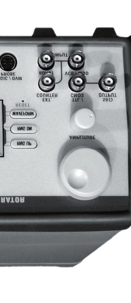

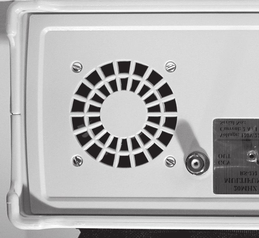
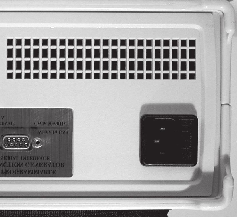

56 PANEL DIAGRAMS PANEL DIAGRAMS: MODEL 4051 MULTIFUNCTION GENERATOR Page
INSTRUCTION MANUAL. Model 4012A. 5 MHz SWEEP FUNCTION GENERATOR. with DIGITAL DISPLAY
 INSTRUCTION MANUAL Model 4012A 5 MHz SWEEP FUNCTION GENERATOR with DIGITAL DISPLAY TEST INSTRUMENT SAFETY WARNING Normal use of test equipment exposes you to a certain amount of danger from electrical
INSTRUCTION MANUAL MANUAL DE INSTRUCCIONES
 INSTRUCTION MANUAL MANUAL DE INSTRUCCIONES MODEL 4017A MODELO 4017A 10 MHz SWEEP FUNCTION GENERATOR with DIGITAL DISPLAY 10MHz GENERADOR DE BARRIDO/FUNCIONES CON EXHIBICION DIGITAL TEST INSTRUMENT SAFETY
INSTRUCTION MANUAL MANUAL DE INSTRUCCIÓN
 INSTRUCTION MANUAL MANUAL DE INSTRUCCIÓN Model 4040A MODELO 4040A 20 MHz SWEEP/FUNCTION GENERATOR with FREQUENCY COUNTER 20 MHz GENERADOR DE BARRIDO/FUNCIONES CON CONTADOR DE FRECUENCIA TEST INSTRUMENT
INSTRUCTION MANUAL MODEL 4010A. 2 MHz FUNCTION GENERATOR MANUAL DE INSTRUCCIONES MODELO 4010A. 2MHz GENERADOR DE FUNCIONES
 INSTRUCTION MANUAL MANUAL DE INSTRUCCIONES MODEL 4010A MODELO 4010A 2 MHz FUNCTION GENERATOR 2MHz GENERADOR DE FUNCIONES TEST INSTRUMENT SAFETY WARNING Normal use of test equipment exposes you to a certain
Model 4007DDS. 7 MHz Sweep Function Generator
 Model 4007DDS 7 MHz Sweep Function Generator 1 Model 4007DDS - Instruction Manual Limited Two-Year Warranty B&K Precision warrants to the original purchaser that its products and the component parts thereof,
Introduction. Specifications. Features. Controls. Model 103
 Index Page # Model 103 2 Introduction 2 Specifications 2 Features 2 Controls 2 Hints and Tips 3 Input Sensitivity (typical) 3 RF Signal Strength Bargraph 3 Frequency Display Resolution 3 Model 104 4 Introduction
DDS Function Generator
 Model: 4007B, 4013B DDS Function Generator USER MANUAL Safety Summary The following safety precautions apply to both operating and maintenance personnel and must be observed during all phases of operation,
CIRCUIT-TEST ELECTRONICS
 USER'S MANUAL Sweep Function Generator with Counter SWF-8030 CIRCUIT-TEST ELECTRONICS www.circuittest.com TABLE OF CONTENTS SAFETY INFORMATION...page 3 INTRODUCTION... 4 SPECIFICATIONS... 5 FRONT PANEL
HP 33120A Function Generator / Arbitrary Waveform Generator
 Note: Unless otherwise indicated, this manual applies to all Serial Numbers. The HP 33120A is a high-performance 15 MHz synthesized function generator with built-in arbitrary waveform capability. Its combination
Sweep Function Generator with External Frequency Counter Instruction Manual
 4005 Sweep Function Generator with External Frequency Counter Instruction Manual Revision: 11/2010 2 Model 4005 5MHz Sweep/Function Generator Thank you for purchasing the Model 4005. For proper use of
Model Hz to 10MHz Precision Phasemeter. Operating Manual
 Model 6610 1Hz to 10MHz Precision Phasemeter Operating Manual Service and Warranty Krohn-Hite Instruments are designed and manufactured in accordance with sound engineering practices and should give long
MULT SWP X1K K VERN START FREQ DURATION AMPLITUDE 0 TTL OUT RAMP
 Signal Generators This document is a quick reference guide to the operation of the signal generators available in the laboratories. Major functions will be covered, but some features such as their sweep
Property of Ramsey Electronics, Inc. Do not reproduce or distribute.
 USER GUIDE JANUARY, 2005 Rev. 1.3 SG560 SIGNAL GENERATOR Copyright Ramsey Electronics, Inc. 2005, All rights reserved 1 TABLE OF CONTENTS Introduction Opening the Box...4 Quick Start...4 Introduction...5
Publication Number ATFxxB Series DDS FUNCTION WAVEFORM GENERATOR. User s Guide
 Publication Number 101201 ATFxxB Series DDS FUNCTION WAVEFORM GENERATOR User s Guide Introduction This user's guide is used for all models of ATFxxB series of DDS function generator. xx in the model number
5MHz FUNCTION GENERATOR
 5MHz FUNCTION GENERATOR MODEL GF-8056 User s Manual Elenco TM Electronics, Inc. Copyright 2004 by Elenco TM Electronics, Inc. All rights reserved. 753117 No part of this book shall be reproduced by any
Instruction Manual. Model 1856D 3.7GHz Frequency Counter
 Instruction Manual Model 1856D 3.7GHz Frequency Counter WARRANTY Warranty service covers a period of one year from the date of original purchase. In case of technical failure within one year, repair service
5MHz FUNCTION GENERATOR
 5MHz FUNCTION GENERATOR MODEL GF-8056 99 Washington Street Melrose, MA 02176 Phone 781-665-1400 Toll Free 1-800-517-8431 Visit us at www.testequipmentdepot.com User s Manual Elenco TM Electronics, Inc.
Digital Function Generator
 Digital Function Generator 13654-99 PHYWE Systeme GmbH & Co. KG Robert-Bosch-Breite 10 37079 Göttingen Germany Tel. +49 (0) 551 604-0 Fax +49 (0) 551 604-107 E-mail info@phywe.de Operating Instructions
WRM-10 TM TRANSFORMER WINDING RESISTANCE METER
 WRM-10 TM TRANSFORMER WINDING RESISTANCE METER USER S MANUAL Vanguard Instruments Company, Inc. 1520 S. Hellman Ave. Ontario, California 91761, USA TEL: (909) 923-9390 FAX: (909) 923-9391 June 2009 Revision
FUNCTION GENERATOR OPERATION MANUAL
 FUNCTION GENERATOR OPERATION MANUAL INDEX 1. Introduction (3) 2. Specifications (3) 3. Working Theory (7) 4. Structure (8) 5. Operation & Maintenance (9) 6. Accessories (14) 1 This instrument is a highly
LAB I. INTRODUCTION TO LAB EQUIPMENT
 1. OBJECTIVE LAB I. INTRODUCTION TO LAB EQUIPMENT In this lab you will learn how to properly operate the oscilloscope Agilent MSO6032A, the Keithley Source Measure Unit (SMU) 2430, the function generator
Arbitrary/Function Waveform Generators 4075B Series
 Data Sheet Arbitrary/Function Waveform Generators Point-by-Point Signal Integrity The Arbitrary/Function Waveform Generators are versatile high-performance single- and dual-channel arbitrary waveform generators
AC/DC True RMS Power Clamp Meter ELECTRONIC TEST INSTRUMENTS MODEL 325
 AC/DC True RMS Power Clamp Meter ELECTRONIC TEST INSTRUMENTS MODEL 325 CONTENTS 1. FEATURES... 2 2. Safety precaution... 2 Symbols Description... 3 3. Specifications... 4 4. Electrical Specifications...
INSTRUCTION MANUAL. Model Model V/30A/150W DC Electronic Load
 INSTRUCTION MNUL Model Model 60/30/ RNING Safety Regulations To avoid electrical shock, do not open the cabinet. Refer servicing to qualified personnel only. To avoid injuries, always disconnect power,
Harris IRT Enterprises Multi-Channel Digital Resistance Tester Model XR
 Harris IRT Enterprises Multi-Channel Digital Resistance Tester Model 6012-06XR Specifications & Dimensions 2 Theory of Operation 3 System Block Diagram 4 Operator Controls & Connectors 5 Test Connections
Model BPG-1P Biphasic Pulse Generator
 MicroProbes for Life Science Model BPG-1P Biphasic Pulse Generator Owner Manual Version: January, 2018 18247-D Flower Hill Way Gaithersburg, MD 20879 Phone: +1 301 330-9788 Fax: +1 301 330-9667 w w w.microprobes.com
2001A. 200KHz Function Generator Instruction Manual. 99 Washington Street Melrose, MA Phone Toll Free
 2001A 200KHz Function Generator Instruction Manual 99 Washington Street Melrose, MA 02176 Phone 781-665-1400 Toll Free 1-800-517-8431 Visit us at www.testequipmentdepot.com WARRANTY Global Specialties
Sampling and Reconstruction
 Experiment 10 Sampling and Reconstruction In this experiment we shall learn how an analog signal can be sampled in the time domain and then how the same samples can be used to reconstruct the original
Model 7000 Low Noise Differential Preamplifier
 Model 7000 Low Noise Differential Preamplifier Operating Manual Service and Warranty Krohn-Hite Instruments are designed and manufactured in accordance with sound engineering practices and should give
RIGOL. Quick Guide. DG2000 Series Function/Arbitrary Waveform Generator. Sept RIGOL Technologies, Inc.
 Quick Guide DG2000 Series Function/Arbitrary Waveform Generator Sept. 2010 RIGOL Technologies, Inc. Guaranty and Declaration Copyright 2010 RIGOL Technologies, Inc. All Rights Reserved. Trademark Information
PIECAL Model 541 Frequency Calibrator with Totalizer Operating Instructions
 PIECAL Model 541 Frequency Calibrator with Totalizer Operating Instructions Easy to use With the Model 541 you can check & calibrate all your frequency instruments and measure flow sensors. Take it into
Berkeley Nucleonics Corp. Model 625 Quick Start Guide
 Berkeley Nucleonics Corp. Model 625 Quick Start Guide 1. Apply power to the 625. After a display of the hardware and software versions and serial number, the unit enters the Basic Sinewave mode of operation.
The University of Jordan Mechatronics Engineering Department Electronics Lab.( ) Experiment 1: Lab Equipment Familiarization
 Experiment 1: Lab Equipment Familiarization") The University of Jordan Mechatronics Engineering Department Electronics Lab.(0908322) Experiment 1: Lab Equipment Familiarization Objectives To be familiar with the main blocks of the oscilloscope and
The University of Jordan Mechatronics Engineering Department Electronics Lab.(0908322) Experiment 1: Lab Equipment Familiarization Objectives To be familiar with the main blocks of the oscilloscope and
RIGOL Data Sheet. DG1000 Series Dual-Channel Function/Arbitrary Waveform Generator. Product Overview. Main Features. Applications. Easy to Use Design
 RIGOL Data Sheet DG1000 Series Dual-Channel Function/Arbitrary Waveform Generator Product Overview DG1000 series Dual-Channel Function/Arbitrary Waveform Generators adopt DDS technology, which enables
PIECAL 311 Automated Universal RTD Calibrator Operating Instructions. Product Description
 Product Description Easy to use With the PIECAL 311 you can check & calibrate all your RTD instruments and measure RTD Sensors. Automatic indication of connections on the display for simple hookups. Take
PIECAL 211 Automated RTD Calibrator Operating Instructions. Product Description. Practical Instrument Electronics
 Product Description Easy to use With the PIECAL 211 you can check & calibrate all your RTD instruments and measure RTD Sensors. Automatic indication of connections on the display for simple hookups. Take
9530/8530 Series Pulse Generator Operating Manual
 9530/8530 Series Pulse Generator Operating Manual QUANTUM COMPOSERS, INC PO Box 4248 Bozeman, MT 59772 (406)582-0227 phone (406)582-0237 fax www.quantumcomposers.com Rev 4.9 Contents 1. INTRODUCTION...
PREMIUMAUDIOVIDEOLIGHTINGANDPOWERPRODUCTS
 FACTOR ELECTRONICS PREMIUMAUDIOVIDEOLIGHTINGANDPOWERPRODUCTS VT-1 / VT-4 Professional Tuners With RBDS Owners Manual Owners Manual IMPORTANT NOTE: THIS OWNER'S MANUAL IS PROVIDED AS AN INSTALLATION AND
INSTRUCTION MANUAL FUNCTION GENERATOR FG-274 B
 INSTRUCTION MANUAL FUNCTION GENERATOR FG-274 B71-0173-11 CONTENTS USING THE PRODUCT SAFELY Ⅰ-Ⅳ 1. FEATURES... 1 2. SPECIFICATIONS... 2 3. FRONT AND REAR PANELS... 5 3.1. Front Panel... 5 3.2. Rear Panel...
B MTS Systems Corp., Model Function Generator
 0189 115585-02 B MTS Systems Corp., 1988 Model 410.81 Function Generator Table of Contents Section 1 Introduction 1.1 Functional Description 1-1 1.2 Specifications 1-2 Section 2 Operation 2.1 Control Mode
ArbStudio Arbitrary Waveform Generators. Powerful, Versatile Waveform Creation
 ArbStudio Arbitrary Waveform Generators Powerful, Versatile Waveform Creation UNMATCHED WAVEFORM UNMATCHED WAVEFORM GENERATION GENERATION Key Features 125 MHz bandwidth 1 GS/s maximum sample rate Long
RIGOL Data Sheet. DG3000 Series Function/Arbitrary Waveform Generator DG3121A, DG3101A, DG3061A. Product Overview. Easy to Use Design.
 RIGOL Data Sheet DG3000 Series Function/Arbitrary Waveform Generator DG3121A, DG3101A, DG3061A Product Overview DG3000 Series Function/Arbitrary Waveform Generators adopt DDS technology, which enables
Metrix Electronics Ltd Tel: +44 (0)
") While signal generators traditionally produce sine waves with accurate frequencies and amplitudes, modern function generators provide capabilities such as pulses, square, triangle, and sawtooth waves.
While signal generators traditionally produce sine waves with accurate frequencies and amplitudes, modern function generators provide capabilities such as pulses, square, triangle, and sawtooth waves.
MODEL 625A SMARTARB BNC A BEST BUY. Eliminates Phase Jitter
 A BEST BUY The Model 625A SMARTARB was designed to provide more operating modes, more functions and more measurement modes than any other unit in its price class. Further upgrading and additions of these
Key Reference. Agilent Technologies E8257D/67D PSG Signal Generators. Manufacturing Part Number: E Printed in USA July 2007
 Agilent Technologies E8257D/67D PSG Signal Generators This guide applies to the following signal generator models: E8267D PSG Vector Signal Generator E8257D PSG Analog Signal Generator Due to our continuing
FREQUENCY SYNTHESIZERS, SIGNAL GENERATORS
 SYNTHESIZED SIGNAL GENERATOR MG3641A/MG3642A 12 khz to 1040/2080 MHz NEW New Anritsu synthesizer technology permits frequency to be set with a resolution of 0.01 Hz across the full frequency range. And
SDI SPECTRADYNAMICS, INC GHZ RUBIDIUM FREQUENCY SYNTHESIZER OPERATING MANUAL
 SPECTRADYNAMICS, INC. 6.834 GHZ RUBIDIUM FREQUENCY SYNTHESIZER RB-1 OPERATING MANUAL SPECTRADYNAMICS, INC 1849 Cherry St. Unit 2 Louisville, CO 80027 Phone: (303) 665-1852 Fax: (303) 604-6088 www.spectradynamics.com
impact VC-500LR Monolight INSTRUCTIONS
 impact lighting equipment and accessories VC-500LR Monolight INSTRUCTIONS Congratulations on your purchase of the Impact VC-500LR Monolight. We feel that it will contribute much to your photographic skill
Instruction Notes for 108A L Sensor Input
 Operation Manual Instruction Notes for 108A L14-1800 Digital Control Module ON/OFF Main Power Switch Alarm Limits/ Cycle Switch Load Outlet (x2) General Description Sensor Input This temperature control
WaveStation Function/Arbitrary Waveform Generators
 WaveStation Function/Arbitrary Waveform Generators Key Features High performance with 14-bit, 125 MS/s and 16 kpts 2 channels on all models Large 3.5 color display for easy waveform preview Over 40 built-in
WaveStation Function/Arbitrary Waveform Generators
 WaveStation Function/Arbitrary Waveform Generators Key Features High performance with 14-bit, 125 MS/s and 16 kpts 2 channels on all models Large 3.5 color display for easy waveform preview Over 40 built-in
SRVODRV REV7 INSTALLATION NOTES
 SRVODRV-8020 -REV7 INSTALLATION NOTES Thank you for purchasing the SRVODRV -8020 drive. The SRVODRV -8020 DC servo drive is warranted to be free of manufacturing defects for 1 year from the date of purchase.
Frequency Calibrator with Totalizer
 Frequency Calibrator with Totalizer Model 942 0.001% accuracy Locked to high stability crystal Six real world ranges 1 to 20000 counts-per-hour to 2000.0 counts-per-minute 0.01 to 999.99 Hz to 9999.9 Hz
PIECAL 311 Automated Universal RTD Calibrator Operating Instructions. Product Description. Practical Instrument Electronics
 Product Description Easy to use With the PIECAL 311 you can check & calibrate all your RTD instruments and measure RTD Sensors. Automatic indication of connections on the display for simple hookups. Take
Signal Forge 2500M Frequency Expansion Module. 1.5 GHz to 2.6 GHz. User Manual
 TM TM Signal Forge 2500M Frequency Expansion Module 1.5 GHz to 2.6 GHz User Manual Technical Support Email: Support@signalforge.com Phone: 512.275.3733 x2 Contact Information Web: www.signalforge.com Sales
OPERATION & SERVICE MANUAL FOR FC 110 AC POWER SOURCE
 OPERATION & SERVICE MANUAL FOR FC 100 SERIES AC POWER SOURCE FC 110 AC POWER SOURCE VERSION 1.3, April 2001. copyright reserved. DWG No. FC00001 TABLE OF CONTENTS CHAPTER 1 INTRODUCTION... 1 1.1 GENERAL...
PHYSICS 171 UNIVERSITY PHYSICS LAB II. Experiment 4. Alternating Current Measurement
 PHYSICS 171 UNIVERSITY PHYSICS LAB II Experiment 4 Alternating Current Measurement Equipment: Supplies: Oscilloscope, Function Generator. Filament Transformer. A sine wave A.C. signal has three basic properties:
Model and
 Function Generator Model 72-14110 and 72-14111 0 Contents Function Generator... 0 Model 72-14110 and 72-14111... 0 Chapter 1 Safety Information... 3 1.1 Safety Terms and Symbols... 3 1.2 General Safety
PIECAL 211 Automated Universal RTD Calibrator Operating Instructions. Product Description. Practical Instrument Electronics
 Product Description Easy to use With the PIECAL 211 you can check & calibrate all your RTD instruments and measure RTD Sensors. Automatic indication of connections on the display for simple hookups. Take
Agilent 33250A 80 MHz Function / Arbitrary Waveform Generator. User s Guide
 User s Guide Publication Number 33250-90002 (order as 33250-90100 manual set) Edition 2, March 2003 Copyright Agilent Technologies, Inc. 2000, 2003 For Safety information, Warranties, and Regulatory information,
Rigol DG1022A Function / Arbitrary Waveform Generator
 Rigol DG1022A Function / Arbitrary Waveform Generator The Rigol DG1000 series Dual-Channel Function/Arbitrary Waveform Generator adopts DDS (Direct Digital Synthesis) technology to provide stable, high-precision,
WaveStation Function/Arbitrary Waveform Generators
 Function/Arbitrary Waveform Generators Key Features High performance with 14-bit waveform generation, up to 500 MS/s sample rate and up to 512 kpts memory 2 channels on all models Large color display for
DSTS-3B DEPTHSOUNDER TEST SET OPERATOR S MANUAL
 Page 1 1.0 INTRODUCTION DSTS-3B DEPTHSOUNDER TEST SET OPERATOR S MANUAL The DSTS-3B is a full-featured test set designed for use with all types of echo sounders from small flashers to large commercial
Dual Channel Function/Arbitrary Waveform Generators 4050B Series
 Data Sheet Dual Channel Function/Arbitrary Waveform Generators The Dual Channel Function/ Arbitrary Waveform Generators are capable of generating stable and precise sine, square, triangle, pulse, and arbitrary
LAB I. INTRODUCTION TO LAB EQUIPMENT
 LAB I. INTRODUCTION TO LAB EQUIPMENT 1. OBJECTIVE In this lab you will learn how to properly operate the basic bench equipment used for characterizing active devices: 1. Oscilloscope (Keysight DSOX 1102A),
Frequency Calibrator with Totalizer
 99 Washington Street Melrose, MA 02176 Phone 781-665-1400 Toll Free 1-800-517-8431 Frequency Calibrator with Totalizer Model 942 0.001% accuracy Locked to high stability crystal Six real world ranges 1
Model Operating Manual
 Model 7500 DC to 1MHz Wideband Power Amplifier Operating Manual Copyright 2004. All rights reserved. Contents of this publication may not be reproduced in any form without the written permission of Krohn-Hite
Dual Channel Function/Arbitrary Waveform Generators 4050 Series
 Data Sheet Dual Channel Function/Arbitrary Waveform Generators The Dual Channel Function/Arbitrary Waveform Generators are capable of generating stable and precise sine, square, triangle, pulse, and arbitrary
Dual Channel Function/Arbitrary Waveform Generators 4050 Series
 Data Sheet Dual Channel Function/Arbitrary Waveform Generators The Dual Channel Function/Arbitrary Waveform Generators are capable of generating stable and precise sine, square, triangle, pulse, and arbitrary
ArbStudio Arbitrary Waveform Generators
 ArbStudio Arbitrary Waveform Generators Key Features Outstanding performance with 16-bit, 1 GS/s sample rate and 2 Mpts/Ch 2 and 4 channel models Digital pattern generator PWM mode Sweep and burst modes
P G A Digital Stimulator Instruction Manual
 P G 4 0 0 0 A Digital Stimulator Instruction Manual 2005 Cygnus Technology, Inc. Technology, Inc. P.O.Box 219 Delaware Water Gap, PA 18327 Tel: (570) 424-5701 Fax: (570) 424-5630 Email: sales@cygnustech.com
Arbitrary/Function Generator AFG1000 Series Datasheet
 Arbitrary/Function Generator AFG1000 Series Datasheet 99 Washington Street Melrose, MA 02176 Phone 781-665-1400 Toll Free 1-800-517-8431 Visit us at www.testequipmentdepot.com Compatible with TekSmartLab
Data Sheet. DG1000 series Dual-Channel Function/Arbitrary Waveform Generators. Product Overview. Main Features. Applications. Easy to Use Design
 Data Sheet DG1000 Series Dual-Channel Function/Arbitrary Waveform Generator Product Overview DG1000 series Dual-Channel Function/Arbitrary Waveform Generators adopt Direct Digital Synthesis (DDS) technology,
Function Generator Guide Tektronix AFG3102
 Tektronix AFG3102 ersion 2008-Jan-1 Dept. of Electrical & Computer Engineering Portland State University Copyright 2008 Portland State University 1 Basic Information This guide provides basic instructions
RIGOL Data Sheet. DG2000 Series Function/Arbitrary Waveform Generator DG2041A, DG2021A. Product Overview. Main Features.
 RIGOL Data Sheet DG2000 Series Function/Arbitrary Waveform Generator DG2041A, DG2021A Product Overview DG2000 Series Function/Arbitrary Waveform Generators adopt DDS technology, which enables to generate
INSTRUCTION MANUAL MODEL 2455T SUBCARRIER MODULATOR
 INSTRUCTION MANUAL MODEL 2455T SUBCARRIER MODULATOR Data, drawings, and other material contained herein are proprietary to Cross Technologies, Inc., and may not be reproduced or duplicated in any form
9200 Series, 300 MHz Programmable Pulse Generator
 9200 Series, 300 MHz Programmable Pulse Generator Main Features Variable edge pulses (1 nsec to 1 msec) at rates to 250 MHz Fast 300 psec edges to 300 MHz Wide output swings to 32 V at pulse rates to 50
RIGOL Data Sheet. DS1000E, DS1000D Series Digital Oscilloscopes DS1102E, DS1052E, DS1102D, DS1052D. Product Overview. Easy to Use Design.
 RIGOL Data Sheet DS1000E, DS1000D Series Digital Oscilloscopes DS1102E, DS1052E, DS1102D, DS1052D Product Overview The DS1000E, DS1000D series instruments are economical, high-performance digital oscilloscopes.
Operator Manual 1.4 FRACSIM MINI
 FracSim Meters FracSim Meters was founded with the intention of providing specifically designed tools for the well service industry. Our goal is to provide quality tools with a robust design to meet the
Advanced Test Equipment Rentals ATEC (2832)
") Established 1981 Advanced Test Equipment Rentals www.atecorp.com 800-404-ATEC (2832) INSTRUCTION MANUAL MODEL 960 SERIES MICRO SWEEP 1 TO 18.0 GHz MICROWAVE GENERATORS 1985 Wavetek THIS DOCUMENT CONTAINS
Established 1981 Advanced Test Equipment Rentals www.atecorp.com 800-404-ATEC (2832) INSTRUCTION MANUAL MODEL 960 SERIES MICRO SWEEP 1 TO 18.0 GHz MICROWAVE GENERATORS 1985 Wavetek THIS DOCUMENT CONTAINS
BLD75-1. Bilevel Step Motor Driver. User s Guide. #L010125
 BLD75-1 Bilevel Step Motor Driver User s Guide A N A H E I M A U T O M A T I O N #L010125 1 Features Unipolar Operation 10 Amps per Phase Operating Current (Kick Current) 7 Amps per Phase Standstill Current
PIN/PINLESS DEEP SENSING MOISTURE METER WITH SPHERICAL SENSOR AND REMOTE PROBE
 99 Washington Street Melrose, MA 02176 Phone 781-665-1400 Toll Free 1-800-517-8431 Visit us at www.testequipmentdepot.com PIN/PINLESS DEEP SENSING MOISTURE METER WITH SPHERICAL SENSOR AND REMOTE PROBE
RIGOL. Quick Guide. DG1000 Series Dual-Channel Function/Arbitrary Waveform Generator. Jul RIGOL Technologies, Inc.
 Quick Guide DG1000 Series Dual-Channel Function/Arbitrary Waveform Generator Jul. 2012 RIGOL Technologies, Inc. Guaranty and Declaration RIGOL Copyright 2011 RIGOL Technologies, Inc. All Rights Reserved.
The Oscilloscope. Vision is the art of seeing things invisible. J. Swift ( ) OBJECTIVE To learn to operate a digital oscilloscope.
 OBJECTIVE To learn to operate a digital oscilloscope.") The Oscilloscope Vision is the art of seeing things invisible. J. Swift (1667-1745) OBJECTIVE To learn to operate a digital oscilloscope. THEORY The oscilloscope, or scope for short, is a device for drawing
The Oscilloscope Vision is the art of seeing things invisible. J. Swift (1667-1745) OBJECTIVE To learn to operate a digital oscilloscope. THEORY The oscilloscope, or scope for short, is a device for drawing
High Performance Microphone Splitter. Artcessories. User's Manual
 High Performance Microphone Splitter Artcessories User's Manual IMPORTANT SAFETY INSTRUCTION READ FIRST This symbol, whenever it appears, alerts you to the presence of uninsulated dangerous voltage inside
Model 310H Fast 800V Pulse Generator
 KEY FEATURES Temperature Stability +/-5ppm 100 V to 800 V into 50 Ω
Key Reference. Agilent Technologies E8663B Analog Signal Generator
 Agilent Technologies E8663B Analog Signal Generator For the latest revision of this guide, go to http://www.agilent.com/find/e8663b and click Product Library. Manufacturing Part Number: E8663-90004 Printed
INSTRUCTION MANUAL MODEL 2779 SUBCARRIER MODULATOR
 INSTRUCTION MANUAL MODEL 2779 SUBCARRIER MODULATOR Data, drawings, and other material contained herein are proprietary to Cross Technologies, Inc., and may not be reproduced or duplicated in any form without
80MHz/50MHz Arbitrary Function Generator
 80MHz/50MHz Arbitrary Function Generator AFG-3000 Series NEW The AFG-3000 Series is an Arbitrary Waveform and Digital-Synthesized Function Generator designed for industrial, scientific research and educational
Table of Contents 9.0 WARRANTY. 1.0 Introduction Package Contents. 2.0 Safety Instructions Overview...003
 9.0 WARRANTY Table of Contents ELECTROMATIC Equipment Co., Inc. (ELECTROMATIC) warrants to the original purchaser that this product is of merchantable quality and confirms in kind and quality with the
R9999 ROBERTS. PLL Synthesised 3 band radio with station name display. Sound for Generations. Please read this manual before use
 ROBERTS Sound for Generations R9999 PLL Synthesised 3 band radio with station name display Please read this manual before use Contents Important Information... 1 Automatic plug and play setup... 2 Controls...
25 MHz Arbitrary Function Generator
 Model: 4075, 4078 25 MHz Arbitrary Function Generator USER MANUAL SERVICE INFORMATION Warranty Service: Please go the support and service section on our website www.bkprecision.com to obtain a RMA #. Return
PAMS. User s Manual. Portable Attenuation Measurement System. The solution for making easy shielding effectiveness measurements.
 PAMS Portable Attenuation Measurement System User s Manual The solution for making easy shielding effectiveness measurements. 310-010042-001 TABLE OF CONTENTS Warranty Statement 1 Chapter 1 General Information
Series 3000 Model R-107A
 Series 3000 Model R-107A DUAL TONE SENDER INSTRUCTION MANUAL Monroe Electronics 100 Housel Ave Lyndonville NY 14098 800-821-6001 585-765-2254 fax 585-765-9330 monroe-electronics.com Printed in USA Copyright
SL300 Snow Depth Sensor USL300 SNOW DEPTH SENSOR. Revision User Manual
 USL300 SNOW DEPTH SENSOR Revision 1.1.2 User Manual 1 Table of Contents 1. Introduction... 3 2. Operation... 3 2.1. Electrostatic Transducer... 4 2.2. SL300 Analog Board... 4 2.3. SL300 Digital Circuit
Model 4402B. Ultra-Pure Sinewave Oscillator 1Hz to 110kHz Typical Distortion of % Serial No. Operating Manual
 Model 4402B Ultra-Pure Sinewave Oscillator 1Hz to 110kHz Typical Distortion of 0.0005% Serial No. Operating Manual 15 Jonathan Drive, Unit 4, Brockton, MA 02301 U.S.A. Tel: (508) 580-1660; Fax: (508) 583-8989
8120 FUNCTION GENERATOR Operation Manual
 8120 FUNCTION GENERATOR Operation Manual Copyright Copyright 1996 by this company. All rights reserved. No part of this publication may be reproduced in any form or by any means without the written permission
TG1010A AIM & THURLBY THANDAR INSTRUMENTS. 10MHz programmable DDS function generator. Direct Digital Synthesis
 AIM & THURLBY THANDAR INSTRUMENTS TG1010A 10MHz programmable DDS function generator Arbitrary Waveform Capability, Extensive Modulation Modes Direct Digital Synthesis All the versatility of a function
GM8036 Laser Sweep Optical Spectrum Analyzer. Programming Guide
 GM8036 Laser Sweep Optical Spectrum Analyzer Programming Guide Notices This document contains UC INSTRUMENTS CORP. proprietary information that is protected by copyright. All rights are reserved. This
Operating Guide. For Series 2 & 3 Phantoms PMR-GP2
 PMR-GP2 For Series 2 & 3 Phantoms Operating Guide PMR-HH3 Table of Contents Introduction 3 Features 5 Installation - GP2,3 6 Installation - HH2,3 12 Operation 13 Tips & Troubleshooting 20 Specifications