3 When acknowledgment is received, you hear. short, medium-pitched tone sounds. four tones; alarm ends; radio exits. Send an Emergency Call
|
|
|
- Ginger Rose
- 6 years ago
- Views:
Transcription


1
2
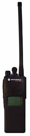
3 ASTRO XTS 1500 Digital Portable Radio, Model 1.5 Quick Reference Card Product Safety and RF Exposure Compliance! C a u t i o n Before using this product, read the operating instructions for safe usage contained in the Product Safety and RF Exposure booklet enclosed with your radio. ATTENTION! This radio is restricted to occupational use only to satisfy FCC RF energy exposure requirements. Before using this product, read the RF energy awareness information and operating instructions in the Product Safety and RF Exposure booklet enclosed with your radio (Motorola Publication part number C98) to ensure compliance with RF energy exposure limits. 3-Position Rotary Switch Channel Select Knob On/Off/ Volume Knob Top Button _ Top Side Button _ Speaker/Mic PTT Button Display Side Button 1 _ Side Button 2 _ Write your radio s programmed features on the dashed lines. Radio On/Off 1 On On/Off/Volume knob clockwise. 2 Off On/Off/Volume knob counterclockwise. Zones/Channels 1 Zone Move Zone switch to desired zone. 2 Channel Turn Channel Selector knob to desired channel. Receive/Transmit 1 Radio on and select zone/channel. 2 Listen for a transmission. OR Press and hold Volume Set button. Release Volume Set button. OR Press Monitor button and listen for activity. 3 Adjust volume, if necessary. 4 Press and hold PTT to transmit; release to listen. Send an Emergency Alarm 1 Radio on and press Emergency button. You see red LED; you hear short, medium-pitched tone. 2 Display shows EMERGENCY. 3 When acknowledgment is received, you hear four tones; alarm ends; radio exits emergency. Send an Emergency Call 1 Radio on and press Emergency button. A short, medium-pitched tone sounds. 2 Press and hold PTT. Announce your emergency into the microphone. 3 Release PTT to end call. 4 Press and hold Emergency button for one second to exit. Answer a Phone Call 1 Phone-like ringing, LED blinks GREEN, PHONE CALL and m are displayed. 2 Press Call Response button. 3 Press PTT button to talk; release to listen. 4 Press Call Response button again to hang up.
4 Display Status Symbols m Call Received. Receiving an individual call. p View Mode. The radio is in the view mode. s Received Signal Strength Indication (RSSI). Received signal strength for the current site (trunking only). The more stripes in the symbol, the stronger the signal. b Battery. Conventional = Blinks when the battery is low. Smart = The number of bars (0-3) shown indicates the charge remaining in your battery. Note: Smart battery will be available at a future date. r Talkaround. You are talking directly to another radio or through a repeater. On = direct Off = repeater C Monitor (Carrier Squelch). This channel is being monitored. T Scan. The radio is scanning a scan list.
5 This declaration is applicable to your radio only if your radio is labeled with the FCC logo shown below. DECLARATION OF CONFORMITY Per FCC CFR 47 Part 2 Section (a) Responsible Party Name: Motorola, Inc. Address: 1301 E. Algonquin Rd, Schaumburg, IL USA Phone Number: Hereby declares that the product: Model Name: XTS 1500 conforms to the following regulations: FCC Part 15, subpart B, section (a), (d) and section (a) Class B Digital Device As a personal computer peripheral, this device complies with Part 15 of the FCC Rules. Operation is subject to the following two conditions: 1. this device may not cause harmful interference, and 2. this device must accept any interference received, including interference that may cause undesired operation. Note: This equipment has been tested and found to comply with the limits for a Class B digital device, pursuant to part 15 of the FCC Rules. These limits are designed to provide reasonable protection against harmful interference in a residential installation. This equipment generates, uses and can radiate radio frequency energy and, if not installed and used in accordance with the instructions, may cause harmful interference to radio communications. However, there is no guarantee that interference will not occur in a particular installation. If this equipment does cause harmful interference to radio or television reception, which can be determined by turning the equipment off and on, the user is encouraged to try to correct the interference by one or more of the following measures: Reorient or relocate the receiving antenna. Increase the separation between the equipment and receiver. Connect the equipment into an outlet on a circuit different from that to which the receiver is connected. Consult the dealer or an experienced radio/tv technician for help. i
6 Product Safety and RF Exposure Compliance! C a u t i o n Before using this product, read the operating instructions for safe usage contained in the Product Safety and RF Exposure booklet enclosed with your radio. ATTENTION! This radio is restricted to occupational use only to satisfy FCC RF energy exposure requirements. Before using this product, read the RF energy awareness information and operating instructions in the Product Safety and RF Exposure booklet enclosed with your radio (Motorola Publication part number C98) to ensure compliance with RF energy exposure limits. For a list of Motorola-approved antennas, batteries, and other accessories, visit the following web site which lists approved accessories: Computer Software Copyrights The Motorola products described in this manual may include copyrighted Motorola computer programs stored in semiconductor memories or other media. Laws in the United States and other countries preserve for Motorola certain exclusive rights for copyrighted computer programs, including, but not limited to, the exclusive right to copy or reproduce in any form the copyrighted computer program. Accordingly, any copyrighted Motorola computer programs contained in the Motorola products described in this manual may not be copied, reproduced, modified, reverseengineered, or distributed in any manner without the express written permission of Motorola. Furthermore, the purchase of Motorola products shall not be deemed to grant either directly or by implication, estoppel, or otherwise, any license under the copyrights, patents or patent applications of Motorola, except for the normal non-exclusive license to use that arises by operation of law in the sale of a product. ii ASTRO XTS 1500 Model 1.5
7 Documentation Copyrights No duplication or distribution of this document or any portion thereof shall take place without the express written permission of Motorola. No part of this manual may be reproduced, distributed, or transmitted in any form or by any means, electronic or mechanical, for any purpose without the express written permission of Motorola. Disclaimer The information in this document is carefully examined, and is believed to be entirely reliable. However, no responsibility is assumed for inaccuracies. Furthermore, Motorola reserves the right to make changes to any products herein to improve readability, function, or design. Motorola does not assume any liability arising out of the applications or use of any product or circuit described herein; nor does it cover any license under its patent rights, nor the rights of others. iii
8 Notes iv ASTRO XTS 1500 Model 1.5
9 Contents Contents Declaration of Conformity... i Product Safety and RF Exposure Compliance... ii Computer Software Copyrights... ii Documentation Copyrights...iii Disclaimer...iii General Radio Operation... 1 Notations Used in This Manual... 1 XTS 1500 Model 1.5 Radio... 2 Physical Features of the XTS 1500 Model 1.5 Radio... 3 Programmable Features... 4 Display... 5 Backlight... 5 Status Symbols... 6 Light Emitting Diode (LED) Indicators... 7 Alert Tones... 7 Standard Accessories Battery Antenna Belt Clip Universal Connector Cover Remove the Connector Cover Attach the Connector Cover Remote Speaker Microphone Adapter Remove the Adapter Attach the Adapter Radio On and Off Turn the Radio On Turn the Radio Off Zones and Channels Select a Zone Select a Channel Mode Select Button Receive / Transmit Without Using the Volume Set and Monitor Buttons Use the Preprogrammed Volume Set Button Use the Preprogrammed Monitor Button v
10 Contents Conventional Mode Operation...23 Common Radio Features Conventional Squelch Options...25 Analog Squelch...25 PL Defeat...25 Time-Out Timer...26 Emergency...27 Send an Emergency Alarm...27 Send an Emergency Call...28 Scan...30 Turn Scan On and Off...30 View a Scan List...30 Scan List Empty...30 Delete a Nuisance Channel...31 Conventional Scan Only...32 Telephone Calls (Trunking Only)...33 Answer a Phone Call...33 Private Calls (Trunking Only)...34 Answer a Private Call...34 Call Alert Paging...35 Answer a Call Alert Page...35 Repeater or Direct Operation...36 Select Repeater or Direct Operation...36 Special Radio Features PTT ID...37 Transmit...37 Trunking System Controls...37 Failsoft...37 Out-of-Range...38 Site Lock...38 Site View and Change...39 Helpful Tips Radio Care...39 Cleaning...39 Handling...39 Service...40 Battery...40 vi ASTRO XTS 1500 Model 1.5
11 Contents Battery Life Charging the Battery Battery Recycling and Disposal Antenna Radio Operating Frequencies Accessories Antennas Batteries Carry Accessories Belt Clips Body-Worn Chargers Enhanced and Multi-Unit Line Cords Microphones, Remote Speaker Surveillance Accessories Adapters and Adapter Cable CommPort Integrated Microphone/Receivers Earpieces Headsets and Headset Accessories Radio Interface Modules for Ear Microphones Switches Appendix: Maritime Radio Use in the VHF Frequency Range Special Channel Assignments Emergency Channel Non-Commercial Call Channel Operating Frequency Requirements Glossary Commercial Warranty Limited Warranty Index vii
12 Notes viii ASTRO XTS 1500 Model 1.5
13 General Radio Operation Notations Used in This Manual You will notice the use of WARNING, CAUTION, and Note notations throughout this manual. These notations are used to emphasize that safety hazards exist and that care must be taken or observed.! WARNING An operational procedure, practice, condition, etc. exists which may result in injury or death if not carefully observed.! C a u t i o n An operational procedure, practice, condition, etc. exists which may result in damage to the equipment if not carefully observed. Note: An operational procedure, practice, or condition, etc. which is essential to emphasize. The following special notations identify certain items: Example Description Top button SELF TEST Buttons are shown in bold print. Information appearing in the radio s display is shown using the special display font. ASTRO XTS 1500 Model 1.5 1
14 General Radio Operation XTS 1500 Model 1.5 Radio
15 General Radio Operation Physical Features of the XTS 1500 Model 1.5 Radio Item Page Item Page 1 Antenna 8 On/Off/Volume 13 Control Knob 17 2 Top Button 9 Microphone (programmable) 46 3 Light Emitting Diode (LED) 7 10 Top Side (Select) Button (programmable) 4 Speaker 11 Push-to-Talk (PTT) Button 5 Universal Connector 6 Channel Selector Knob (programmable) 7 3-Position Concentric Switch (programmable) Side Button 1 (programmable) 13 Side Button 2 (programmable) 14 Battery Display 5 ASTRO XTS 1500 Model 1.5 3
16 General Radio Operation Programmable Features The programmable controls on your radio can be programmed by a qualified technician to operate certain software-activated features. The features that can be assigned to these controls, and the page numbers where these features can be found, are listed below. Table 1: Programmable Features Feature Page Feature Page Call Response 35 Phone 33 Channel Selection 18 PL Defeat 25 Conventional Squelch Options 25 Repeater/Direct 36 Dynamic Priority 32 Scan On/Off 30 Emergency 27 Site Lock/Unlock 38 Light 5 Site Search 39 Monitor 22 Volume Set 21 Nuisance Delete 31 Zone Selection 18 As an additional guide, please use the empty spaces provided in your Quick Reference Card to indicate the features that are programmed to the various controls for your radio. Additionally, in this manual, all reference to a programmed control is made with reference to the actual feature (for example, the Volume Set button). Any references in this manual to controls that are preprogrammed means that a qualified radio technician must use the radio s programming software to assign a feature to a control. 4
17 General Radio Operation Display This figure is typical of what you see on your radio. The 64 x 96 pixel liquid crystal display (LCD) shows radio status, text, and menu entries. Backlight If poor light conditions make the display difficult to read, turn on the radio s backlight by pressing the Light button. The light will remain on for a preprogrammed time before it turns off automatically, or you can turn it off immediately by pressing the Light button again. ASTRO XTS 1500 Model 1.5 5
18 General Radio Operation Status Symbols The top two rows in the display contain symbols indicating the radio s status. Table 2: Status Symbols Symbol Indication Page m Call Received. Blinks when an Individual Call is received. 33 p View Mode. View a list. 30 s b r C Received Signal Strength Indication (RSSI). The received signal strength for the current site. Trunked only. The more stripes in the symbol, the stronger the received signal. Battery. Conventional = Blinks when the battery is low. Smart = The number of bars (0-3) shown indicates the charge remaining in your battery. Blinks when battery level reaches 10% or less. Note: Smart battery will be available at a future date. Talkaround. On = Talking directly to another radio, not through a repeater. Conventional operation only. Off = Talking through a repeater. Monitor (Carrier Squelch). The selected channel is being monitored. Conventional operation only. T Scan. The radio is scanning a scan list
19 General Radio Operation Light Emitting Diode (LED) Indicators Table 3: LED Indicators This LED Color: RED (Non-blinking) RED (Blinking) GREEN (Blinking) Transmitting Indicates: Channel Busy OR Low Battery (lights while transmitting) Receiving Individual Call Alert Tones Your radio uses alert tones to inform you of radio conditions. Table 4: Alert Tones You hear: Tone Name Heard: Short, Low-Pitched Tone Invalid Key-Press Radio Self-Test Failed Reject Time-Out Timer Warning when the wrong key is pressed. when the radio fails the powerup self test. when an unauthorized request is made. four seconds before time out. ASTRO XTS 1500 Model 1.5 7
20 General Radio Operation Long, Low-Pitched Tone A Group of Low-Pitched Tones (Busy Tone) Short, Medium- Pitched Tone Table 4: Alert Tones (Continued) You hear: Tone Name Heard: No ACK Received Time-Out Timer Timed Out Talk Prohibit/ PTT Inhibit Out-of-Range Invalid Mode Individual Call Warning Tone Busy Valid Key-Press Radio Self-Test Pass Priority Channel Received Emergency Alarm Entry Central Echo when the radio does not receive an acknowledgment. after time out. when the PTT button is pressed, and transmissions are prevented. when the PTT button is pressed, but the radio is out of range of the system. when the radio is set to an unprogrammed channel. when the radio is in Individual Call without any activity for more than 6 seconds. when the system is busy. when the correct key is pressed. when the radio passes its power-up self-test. when activity on a priority channel is received. when entering the emergency state. when the central controller has received a request from a radio. 8
21 General Radio Operation Table 4: Alert Tones (Continued) You hear: Tone Name Heard: Long, Medium- Pitched Tone Volume Set Emergency Exit Failsoft Automatic Call Back A Group of Talk Permit Medium- Pitched Tones Console Acknowledge A Group Of Low Pitched Tones followed by a Group of High Pitched Tines A Group of High Pitched Times followed by a Group of Low Pitched Tones Short, High- Pitched Tone (Chirp) Received Individual Call Scan Alert On Scan Alert Off Low-Battery Chirp Ringing Phone Call Received when volume changed on a quiet channel. upon exiting the emergency state. when the trunking system fails. when the voice channel is available from the previous request. (when pressing the PTT button) verifies the system is accepting transmissions. when a status, emergency alarm, or reprogram request acknowledgment is received. when a Call Alert, or Private Conversation Call is received. when the Scan feature is activated through the pre-programmed button or 3-Position Rotary Switch. when the Scan feature is deactivated through the pre-programmed button or 3-Position Rotary Switch. when the battery is below the preset threshold value. when a landline phone call is received. ASTRO XTS 1500 Model 1.5 9
22 General Radio Operation Standard Accessories Battery! WARNING To avoid a possible explosion: DO NOT replace the battery in any area labeled hazardous atmosphere. DO NOT discard batteries in a fire. Charge the Battery The Motorola approved battery shipped with your radio is uncharged. Prior to using a new battery, charge it for a minimum of 16 hours to ensure optimum capacity and performance. For a list of Motorola approved batteries available for use with your XTS 1500 radio, see Batteries on page 44. Note: When charging a battery attached to a radio, turn the radio off to ensure a full charge. Battery Charger To charge the battery, place the battery, with or without radio, in a Motorola-approved charger. The charger s LED indicates the charging progress; see your charger s user guide. For a list of chargers, see Chargers on page
23 General Radio Operation Attach the Battery 1 With the radio off, fit the three extensions at the bottom of the battery into the bottom slots on the radio. 2 Press both sides at the top of the battery against the radio until both latches click into place. Remove the Battery 1 With the radio off, slide down the latches on the sides of the battery. 2 Pull the top of the battery away from the radio. ASTRO XTS 1500 Model
24 General Radio Operation Smart Battery Condition This feature allows you to view the condition of your Smart Battery. 1 Press the Smart Battery button. CAPACITY 70% INIT 10/01 EST CHGS 11 Note: If a Smart Battery is not powering your radio: SMART BATT DATA NOT AVAILABLE 2 Press the Smart Battery button again to exit. 12
25 General Radio Operation Antenna For information regarding other available antennas, see page 44. Attach the Antenna With the radio off, turn the antenna clockwise to attach it. Remove the Antenna With the radio off, turn the antenna counterclockwise to remove it. ASTRO XTS 1500 Model
26 General Radio Operation Belt Clip Attach the Belt Clip 1 Align the grooves of the belt clip with those of the battery. 2 Press the belt clip downward until you clear a click. Remove the Belt Clip 1 Use a flat-bladed screwdriver to press the belt clip tab away from the battery. 2 Slide the belt clip upward to remove it. 14
27 General Radio Operation Universal Connector Cover The universal connector cover is located on the antenna side of the radio. It is used to connect certain accessories to the radio. Note: To prevent damage to the connector, shield it with the connector cover when not in use. Remove the Connector Cover 1 Insert a flat-bladed screwdriver into the area between the bottom of the cover and the slot below the connector. 2 Hold the top of the cover with your thumb while you pry the bottom of the cover away from the radio with the screwdriver. Attach the Connector Cover 1 Insert the hooked end of the cover into the top of the connector. Press downward on the cover s top to seat it into the slot. 2 Press the cover s lower tab below the connector until it snaps in place. ASTRO XTS 1500 Model
28 General Radio Operation Remote Speaker Microphone Adapter The Remote Speaker Microphone (RSM) adapter is located on the back of the radio, just above the battery. It must be used to connect the RSM accessories (see page 46) to the radio. If the RSM is not used, the adapter should be removed. Remove the Adapter Lift the larger side (below the antenna port) of the adapter away from the radio using your finger. If you cannot easily remove the adapter with your finger, use a small, flat blade screwdriver to pry the larger end side of the adapter away from the radio. Attach the Adapter 1 With the Motorola side of the adapter facing out, snap the smaller end of the adapter into place in the shroud indent, below the On/Off Volume Control Knob. 2 Snap the larger end of the adapter into place in the shroud indent, below the antenna port. 16
29 General Radio Operation Radio On and Off Turn the Radio On Turn the On/Off/Volume Control knob clockwise. If the power-up test is successful, you will briefly see SELF TEST and then the home display. If the power-up test is unsuccessful, you will see ERROR XX/YY. (XX/YY is an alphanumeric code.) Turn off the radio, check the battery, and turn the radio on again. If the radio continues to fail the power-up test, record the ERROR XX/YY code and contact a qualified service technician. SELF TEST ERROR XX/YY Turn the Radio Off Turn the On/Off/Volume Control knob counterclockwise until it clicks. ASTRO XTS 1500 Model
30 General Radio Operation Zones and Channels A zone is a grouping of channels. A channel is a group of radio characteristics, such as transmit/receive frequency pairs. Before you use your radio to receive or send messages, you should select the zone. Select a Zone 1 If a control on your radio has been preprogrammed as the Zone Switch, move the Zone Switch to the position for the zone you want. Note: If the zone you selected is unprogrammed, repeat this step. FIRE DISP NW Long, medium-pitched tone UNPROGRAMMED Select a Channel 1 After you selected the zone you want, turn the preprogrammed Channel Selector knob to the desired channel. 2 If the channel you selected is unprogrammed, select a different channel. Long, medium-pitched tone UNPROGRAMMED 18
31 General Radio Operation Mode Select Button This feature lets you program the current zone and channel to a Mode Select button with a long press on the Mode Select button. After the buttons are programmed, you can return to the preprogrammed zone and channel with a short press on the programmed Mode Select button.the buttons that are assigned for this feature are labeled in the following picture. Top Button Top Side Button Side Button 1 Side Button 2 ASTRO XTS 1500 Model
32 General Radio Operation Receive / Transmit Radio users who switch from analog to digital radios often assume that the lack of static on a digital channel is an indication that the radio is not working properly. This is not the case. Digital technology quiets the transmission by removing the noise from the signal and allowing only the clear voice or data information to be heard. This section emphasizes the importance of knowing how to monitor a channel for traffic before keying-up to send a transmission. Without Using the Volume Set and Monitor Buttons 1 Turn the radio on and select the desired zone and channel. 2 Listen for a transmission. 3 Adjust the Volume Control knob if necessary. 4 Press and hold the PTT button to transmit. The LED lights RED while transmitting. 5 Release the PTT button to receive (listen). 20
33 General Radio Operation Use the Preprogrammed Volume Set Button 1 Turn the radio on and select the desired zone and channel. See Turn the Radio On, page 17 and Zones and Channels, page Press and hold the Volume Set button to hear the volume set tone. 3 Release the Volume Set button. 4 Adjust the Volume Control Knob if necessary. 5 Press and hold the PTT button to transmit. LED lights RED while transmitting. 6 Release the PTT button to receive (listen). ASTRO XTS 1500 Model
34 General Radio Operation Use the Preprogrammed Monitor Button 1 Turn the radio on and select the desired zone and channel. 2 Press the Monitor button and listen for activity. (See the following Conventional Mode Operation.) C 3 Adjust the Volume Control knob if necessary. 4 Press and hold the PTT button to transmit. The LED lights RED while transmitting. 5 Release the PTT button to receive (listen). 22
35 General Radio Operation Conventional Mode Operation 6 Your radio may be programmed to receive Private-Line (PL) calls. 1 Momentarily press the Monitor button to listen for activity. 2 Press and hold the Monitor button to set continuous monitor operation. (The duration of the button press is programmable.) 3 Press the Monitor button again, or the PTT button, to return to the original squelch setting. Note: If you try to transmit on a receive-only channel, you will hear an invalid tone until you release the PTT button. C ASTRO XTS 1500 Model
36 General Radio Operation Notes 24
37 Common Radio Features Conventional Squelch Options Analog Squelch Tone Private Line (PL), Digital Private-Line (DPL), and carrier squelch can be available (preprogrammed) per channel. When in: Carrier squelch (C) PL, DPL This condition occurs: You hear all traffic on a channel. The radio responds only to your messages. PL Defeat With this feature, you can override any coded squelch (DPL, PL, or network ID) that might be programmed to a channel. Place the preprogrammed PL Defeat switch in the PL Defeat position. You can now hear any activity on the channel. The radio is muted if no activity is present. When this feature is active, the Carrier Squelch status indicator (C) will be displayed. C ASTRO XTS 1500 Model
38 Common Radio Features Time-Out Timer The time-out timer turns off your radio s transmitter. The timer is set for 60 seconds at the factory, but it can be programmed from 0 to 7.75 minutes (465 seconds) by a qualified radio technician. 1 Hold down the PTT longer than the programmed time. You will hear a short, lowpitched warning tone, the transmission is cut-off, and the LED will go out until you release the PTT. Short warning tone Transmission is cut-off LED goes out 2 Release the PTT button. LED re-lights Timer resets 3 Press the PTT to re-transmit. Time-out timer restarts. Timer restarts RED LED 26
39 Common Radio Features Emergency If the top (orange) button is programmed to send an emergency signal, then this signal overrides any other communication over the selected channel. Your radio can be programmed for the following: Emergency Alarm Emergency Alarm with Emergency Call Emergency Call Consult a qualified radio technician for emergency programming of your radio. Send an Emergency Alarm An Emergency Alarm will send a data transmission to the dispatcher, identifying the radio sending the emergency. 1 With your radio turned on, press the Emergency button. The current zone/ channel is displayed alternately with EMERGENCY, the LED lights RED, and a tone sounds. Note: If the selected channel does not support emergency, the display shows NO EMERGENCY. Select a channel that does show EMERGENCY. EMERGENCY RED LED Short medium-pitched tone NO EMERGENCY To exit emergency at any time, press and hold the Emergency button for about a second. ASTRO XTS 1500 Model
40 Common Radio Features 2 When you receive the dispatcher s acknowledgment, you see ACK RECEIVED, four tones sound, the alarm ends, and the radio exits the emergency mode. If no acknowledgement is received, you see NO ACKNOWLDG, the alarm ends, and the radio exits the emergency mode. Note: Send an Emergency Call ACK RECEIVED Four tones Alarm ends Radio exits emergency NO ACKNOWLDG For Emergency Alarm with Emergency Call: The radio enters the Emergency Call state either after it receives the dispatcher s acknowledgment, or if you press the PTT button while in Emergency Alarm. Go to step 2 below: Send an Emergency Call. An Emergency Call will send a type of dispatch giving your radio priority access to channels. 1 With your radio turned on, press the Emergency button. The current zone/ channel is displayed alternately with EMERGENCY, and a short, medium-pitched tone sounds. Short tone EMERGENCY Note: To exit emergency at any time, press and hold the Emergency button for about a second. 2 Press and hold the PTT button and announce your emergency into the microphone. 28
41 Common Radio Features 3 Release the PTT button to end the transmission and wait for a response from the dispatcher. 4 Press and hold the Emergency button for about a second to exit emergency. The radio operates in the normal dispatch manner while in Emergency Call, except, if enabled, it will return to one of the following: Using this operation: 1 Tactical/Non- Revert 2 Non-Tactical/ Revert Means you will talk: on the channel you selected before you entered the emergency state. on a preprogrammed emergency channel. The emergency alarm is sent to this same channel. Note: For ALL Emergency signals: You can change channels while in Emergency operation if the new channel is also programmed for Emergency. The emergency alarm or call continues on the new channel. If the new channel is NOT programmed for Emergency, an invalid tone sounds until you exit the Emergency state or change to a channel programmed for emergency. ASTRO XTS 1500 Model
42 Common Radio Features Scan The scan feature allows you to monitor traffic on different channels by scanning a preprogrammed list of channels. The list must be preprogrammed by a qualified technician. Turn Scan On and Off Place the Scan On/Off switch in the On or Off position. The current scan state is displayed. When scan is on, the scan status symbol (T) is displayed. View a Scan List 1 Press and hold the preprogrammed Scan button. 2 Turn the Channel Knob to scroll through the list. 3 Move the Zone Select switch to the desired zone. 4 Press and release the preprogrammed Scan button when finished. Z1 CHAN T p Scan List Empty If the scan list has no members, EMPTY LIST is displayed. EMPTY LIST can be changed by turning scan off, or a qualified technician adds members to the scan list. EMPTY LIST 30
43 Common Radio Features Delete a Nuisance Channel When the radio scans to a channel that you do not wish to hear (nuisance channel), you can temporarily delete the channel from the scan list. 1 When the radio is locked onto the channel to be deleted, press the preprogrammed Nuisance Delete button. Repeat this step to delete more channels. Note: You cannot delete priority channels or the designated transmit channel. 2 The radio continues scanning the remaining channels in the list. To resume scanning the deleted channel, change channels or turn scan off and then back on again. ASTRO XTS 1500 Model
44 Common Radio Features Conventional Scan Only Make a Dynamic Priority Change While the radio is scanning, the dynamic priority change feature lets you temporarily change any channel in a scan list (except the priorityone channel) to the priority-two channel. The replaced priority-two channel becomes a non-priority channel. This change remains in effect until scan is turned off, then scanning reverts back to the preprogrammed state. 1 When the radio is locked onto the channel to be designated as priority-two, press the preprogrammed Dynamic Priority button. Note: The priority-one channel cannot be changed to priority-two. 2 The radio continues scanning the remaining channels in the list. To resume scanning the preprogrammed priority-two channel, you must leave and re-enter scan operation. 32
45 Common Radio Features Telephone Calls (Trunking Only) Use your radio to receive standard phone calls. A landline phone can be used to call a radio. Answer a Phone Call 1 When a phone call is received, you hear a telephone-type ringing, the LED blinks GREEN, the call-received symbol (m) blinks, and PHONE CALL is displayed. 2 Press the Call Response button within 20 seconds after the call indicators begin. 3 Press and hold the PTT button to talk; release it to listen. 4 Press the Call Response button again to hang up and return to the home display. m PHONE CALL Telephone ringing Blinking GREEN LED ASTRO XTS 1500 Model
46 Common Radio Features Private Calls (Trunking Only) These one-to-one calls between two radios are not heard by others in the current talkgroup. The calling radio automatically verifies that the receiving radio is active on the system and that it can display the caller s ID. Answer a Private Call 1 When a private call is received, you hear two alert tones, the LED blinks GREEN, the call-received symbol (m) blinks, and CALL RECEIVD is displayed. 2 Press the Call Response button within 20 seconds. If the caller s name is in the call list, it will be displayed. OR If the name is not in the call list, the caller s ID number is displayed. 3 Press and hold the PTT button to talk; release it to listen. 4 Press the Call Response button again to hang up. m CALL RECEIVD Two tones Blinking GREEN LED 34
47 Common Radio Features Call Alert Paging Call Alert allows your radio to work like a pager. Answer a Call Alert Page 1 When a Call Alert Page is received, you hear four repeating alert tones, the LED blinks GREEN, the call-received symbol (m) blinks, and PAGE RECEIVED is displayed. 2 Press and hold the PTT button to talk, release it to listen. PAGE RECEIVD Four repeating alert tones Blinking GREEN LED m ASTRO XTS 1500 Model
48 Common Radio Features Repeater or Direct Operation Also known as TALKAROUND operation, DIRECT lets you bypass the repeater and connect directly to another radio. The transmit and receive frequencies are the same. REPEATER operation increases the radio s range by connecting with other radios through a repeater. Transmit and receive frequencies are different. Select Repeater or Direct Operation Place the preprogrammed Repeater/Direct switch in Repeater or Direct position. r indicates direct mode. r 36
49 Special Radio Features PTT ID Transmit Your radio s ID number is automatically sent every time the PTT button is pressed. This is a per-channel feature. For digital voice transmissions, your radio s ID is sent continuously during the voice message. Trunking System Controls Failsoft The failsoft system ensures continuous radio communications during a trunked system failure. If a trunking system fails completely, the radio goes into failsoft operation, and automatically switches to its failsoft channel. During failsoft operation: Your radio transmits and receives in conventional operation on a predetermined frequency. You hear a medium-pitched tone every 10 seconds. Your radio s FAILSOFTID Medium-pitched tone When the trunking system returns to normal operation, your radio automatically leaves failsoft operation and returns to trunked operation. ASTRO XTS 1500 Model
50 Special Radio Features Out-of-Range If you go out of the range of the system, and can no longer lock onto a control channel: The display shows OUT OF RANGE and the currently selected zone/ channel combination, and/or you hear a low-pitched tone. Your radio remains in this out-ofrange condition until it locks onto a control channel, or it locks onto a failsoft channel, or it is turned off. Your OUT radio s OF RANGE ID AND/OR Low-pitched tone Locks onto a control channel, or Locks onto a failsoft channel, or Turned off. Site Lock This feature allows your radio to lock onto a specific site and not roam among wide-area talkgroup sites. This feature should be used with caution, since it inhibits roaming to another site in a wide-area system. 1 Press the Site Lock/Unlock button. The current lock state is momentarily displayed. 2 Press and hold the Site Lock/ Unlock button until you see the desired lock state. OR OR SITE LOCKED SITE UNLOCKED SITE LOCKED SITE UNLOCKED 38
51 Special Radio Features Site View and Change View the Current Site Momentarily press the preprogrammed Site Search button. The display shows either the number of the current site and its corresponding Received Signal Strength Indicator (RSSI) symbol (s). (See Table 2 on page 6. OR If the radio is scanning for a new site, the display momentarily shows SCANING SITE. s SITE 2 SCANING SITE Change the Current Site Press and hold down the preprogrammed Site Search button to manually force the change to a new site. You hear a tone, and the display shows SCANING SITE while the radio scans for a new site. The radio returns to the home display when it finds a new site. Tone SCANING SITE ASTRO XTS 1500 Model
52 Special Radio Features Notes 40
53 Helpful Tips Helpful Tips Radio Care Cleaning To clean the external surfaces of your radio: 1 Combine one teaspoon of mild dishwashing detergent to one gallon of water (0.5% solution). 2 Apply the solution sparingly with a stiff, non-metallic, shortbristled brush, making sure excess detergent does not get entrapped near the connectors, controls or crevices. Dry the radio thoroughly with a soft, lint-free cloth. 3 Clean battery contacts with a lint-free cloth to remove dirt or grease.! C a u t i o n Do not use solvents to clean your radio. Spirits may permanently damage the radio housing. Do not submerge the radio in the detergent solution. Handling Do not pound, drop, or throw the radio. Never carry the radio by the antenna. Avoid subjecting the radio to an excess of liquids. Avoid subjecting the radio to corrosives, solvents or spirits. Do not disassemble the radio. Keep the accessory-connector cover in place until ready to use the connector. Replace the cover immediately once the accessory has been disconnected. ASTRO XTS 1500 Model
54 Helpful Tips Service Proper repair and maintenance procedures will assure efficient operation and long life for this product. A Motorola maintenance agreement will provide expert service to keep this and all other communication equipment in perfect operating condition. A nationwide service organization is provided by Motorola to support maintenance services. Through its maintenance and installation program, Motorola makes available the finest service to those desiring reliable, continuous communications on a contract basis. For a contract service agreement, please contact your nearest Motorola service or sales representative, or an authorized Motorola dealer. Express Service Plus (ESP) is an optional extended service coverage plan, which provides for the repair of this product for a period of three years from the date of shipment from the factory, or the date of delivery if purchased from an authorized Motorola two-way radio dealer. For more information about ESP, contact the Motorola Radio Support Center, 2204 Galvin Drive, Elgin, IL 60123, Battery Battery Life Battery life is determined by several factors. Among the more critical are the regular overcharge of batteries and the average depth of discharge with each cycle. Typically, the greater the overcharge and the deeper the average discharge, the fewer cycles a battery will last. For example, a battery which is overcharged and discharges 100% several times a day, will last fewer cycles than a battery that receives less of an overcharge and is discharged to 50% per day. Further, a battery which receives minimal overcharging and averages only 25% discharge, will last even longer. 40
55 Helpful Tips Charging the Battery Motorola batteries are designed specifically to be used with a Motorola charger and vice-versa. Charging in non-motorola equipment may lead to battery damage and void the battery warranty. Motorola-authorized battery chargers may not charge batteries other than the ones listed on page 44. The battery should be at about 77 F (25 C) (room temperature), whenever possible. Charging a cold battery (below 50 F [10 C]) may result in leakage of electrolyte and ultimately in failure of the battery. Charging a hot battery (above 95 F [35 C]) results in reduced discharge capacity, affecting the performance of the radio. Motorola rapid-rate battery chargers contain a temperature-sensing circuit to ensure that batteries are charged within the temperature limits stated above. Battery Charge Status Your radio can indicate your battery s charge status by the following: LED and Sounds you can see the LED flash red when the PTT Button is pressed indicating low battery. you hear a low-battery chirp (short, high-pitched tone) Conventional Fuel Gauge Symbol A blinking fuel gauge symbol (b) is displayed only when the battery voltage drops to low level. In this case, replace the battery with a fully charged one. Smart Fuel Gauge Symbol Note: Smart battery will be available at a future date. Consult the Smart Battery manual. All conditions must be met for a battery to be classified as a Smart Battery. When your radio has a Smart Battery installed, the fuel gauge symbol is always displayed. ASTRO XTS 1500 Model
56 Helpful Tips Gauge shows: b If the battery s charge is: 71% to 100% full j 41% to 70% k 11% to 40% l 10% or less (at 10%, the gauge begins blinking) Replace the battery with a fully charged one when the fuel gauge shows the lowest level. Battery Recycling and Disposal Nickel-cadmium (NiCd) rechargeable batteries can be recycled. However, recycling facilities may not be available in all areas. Under various U.S. state laws and the laws of several other countries, NiCd batteries must be recycled and cannot be disposed of in landfills or incinerators. Contact your local waste management agency for specific requirements and information in your area. Motorola fully endorses and encourages the recycling of NiCd batteries. In the U.S. and Canada, Motorola participates in the nationwide Rechargeable Battery Recycling Corporation (RBRC) program for NiCd battery collection and recycling. Many retailers and dealers participate in this program. For the location of the drop-off facility closest to you, access RBRC's Internet web site at or call BATTERY. This internet site and telephone number also provide other useful information concerning recycling options for consumers, businesses, and governmental agencies. 42
57 Helpful Tips Antenna Radio Operating Frequencies Before installing the antenna, make sure it matches your radio s operating frequency. Antennas are frequency sensitive and are color coded according to their frequency range. The color code indicator is located in the center of the antenna s base. color The following antenna types are compatible with your radio: Antenna Type Approx. Length in. mm. Insulato r Color Code Frequenc y Range (MHz) Antenna Kit No. VHF whip, wideband RED NAD6563 VHF helical YELLOW NAD6566 VHF helical BLACK NAD6567 VHF helical BLUE NAD6568 UHF helical RED NAE6546 UHF helical GREEN NAE6547 UHF helical BLACK NAE6548 UHF whip, wideband GRAY NAE MHz whip, halfwave RED NAF MHz whip, halfwave BLUE NAF MHz dipole RED NAF MHz dipole BLUE NAF /900 MHz stubby, quarterwave WHITE NAF /800 MHz whip 7 17 GREEN NAF5080 ASTRO XTS 1500 Model
58 Accessories Accessories Motorola provides the following approved accessories to improve the productivity of your XTS 1500 portable two-way radio. For a list of Motorola-approved antennas, batteries, and other accessories, visit the following web site which lists approved accessories: Antennas NAD6563 NAD6566 NAD6567 NAD6568 NAE6546 NAE6547 NAE6548 NAE6549 NAF5037 NAF5038 NAF5039 NAF5040 NAF5042 NAF5080 VHF whip ( MHz) VHF ( MHz) VHF ( MHz) VHF ( MHz) UHF ( MHz) UHF ( MHz) UHF ( MHz) UHF whip ( MHz) 800 MHz whip, halfwave ( MHz) 900 MHz whip, halfwave ( MHz) 800 MHz dipole ( MHz) 900 MHz dipole ( MHz) 800/900 MHz stubby, quarterwave ( MHz) 700/800 MHz whip ( MHz) Batteries *NNTN6263 NTN9815 NTN9816 NiMH ultra-high-capacity, Immersible, IMPRES NiCd high-capacity NiCd high-capacity, Factory Mutual Intrinsically Safe 44
59 Accessories *NTN9857 *NTN9858 NiMH ultra-high-capacity, Factory Mutual Intrinsically Safe, IMPRES NiMH ultra-high-capacity, IMPRES * Batteries include an over-discharge protection circuit (similar to those in Li-Ion batteries) to extend life of batteries by preventing excessive battery discharge during customer use. Motorola strongly recommends charging these batteries with Motorola-approved IMPRES TM desktop charges programmed with version 3.4 of the IMPRES TM desktop charger software. Carry Accessories Belt Clips HLN6853 Belt clip, 2 1/4 inch Body-Worn NNTN4115 NNTN4116 NNTN4117 NLN6349 NTN5243 TDN9675 Carrying case, leather with 3-in. swivel belt loop and T-strap Carrying case, leather with 2.5-in. swivel belt loop and T-strap Carrying case, leather with 3-in. belt loop and T-strap Shoulder strap for carrying radio Shoulder strap for carrying radio Wrist strap for carrying radio Chargers NLN7967 NLN7968 NTN1168 Wall-mount kit for multi-unit charger Rack-mount kit for multi-unit charger Single-unit dual rate, rapid charger 120V ASTRO XTS 1500 Model
60 Accessories NTN1169 NTN1170 NTN1177 NTN1178 NTN1179 NTN1667 NTN1668 NTN1669 NTN1873 NTN1874 NTN1875 NTN4796 NTN7209 RLN4884 Single-unit dual rate, rapid charger 220V (2-prong Euro plug) Single-unit dual rate, rapid charger 240V (3-prong UK plug) Multi-unit, dual rate, rapid charger 110V Multi-unit, dual rate, rapid charger 240V (3-prong UK plug) Multi-unit, rapid charger 240V (UK 13 MAP Plug) Tri-chemistry, 110V Tri-Chemistry, 220V Single Unit Charger (2 Prong Euro Plug) Tri-chemistry, 230V IMPRES rapid charger 110V single-unit IMPRES rapid charger 220V single-unit IMPRES rapid charger 240V single-unit Multi-unit, tri-chemistry, rapid rate, 110V Single-unit dual rate, rapid charger w/o cord Single-unit Travel Charger Enhanced and Multi-Unit Line Cords NTN7373 NTN7374 NTN V interchangeable line 220V interchangeable line (2-prong Euro plug) 240V interchangeable line (3-prong UK plug) Microphones, Remote Speaker NMN6191 Remote speaker mic, noise-canceling (includes 6.0-ft. coiled cord assembly, 3.5-mm earjack, swivel clip, quick disconnect) 46
61 Accessories NMN6193 NNTN4285 ZMN6031 ZMN6032 ZMN6038 ZMN6039 *RMN5074 *RMN5073 *RMN5072 Remote speaker mic Remote speaker mic adapter Speaker mic, 3-piece Speaker mic, 2-piece Speaker mic, 2-piece, extra loud Speaker mic, 3-piece, extra loud 18 inch Public Safety Microphone 24 inch Public Safety Microphone 30 inch Public Safety Microphone Note: Accessories *RMN5074, *RMN5073 and *RMN5072 are not to be used with VHF band radios. For 900MHz band radios, use these accessories only with antenna NAF5042. Surveillance Accessories Adapters and Adapter Cable BDN6673 BDN6676 NTN8613 Headset adapter cable (for use with BDN6635 and BDN6645) Adapter Surveillance accessory adapter CommPort Integrated Microphone/Receivers NTN1624 NTN1625 NTN1663 CommPort with palm PTT CommPort ear mic with PTT for noise levels up to 100 db (requires BDN6676 adapter) CommPort ear mic with ring PTT for noise levels up to 100 db (requires BDN6676 adapter) ASTRO XTS 1500 Model
62 Accessories NTN1736 CommPort ear mic with snap-on side PTT for noise levels up to 100 db (requires BDN6676 adapter) Earpieces BDN6641 BDN6664 BDN6665 BDN6666 BDN6667 BDN6668 BDN6669 BDN6670 BDN6677 BDN6678 BDN6719 BDN6726 BDN6727 BDN6728 BDN6729 BDN6730 BDN6731 Ear mic, high noise level up to 105 db, grey (must order BDN6671 interface module) Earpiece with standard earphone, beige Earpiece with extra-loud earphone (exceeds OSHA limits), beige Earpiece with volume control, beige Earpiece, mic and PTT combined, beige Earpiece, mic and PTT separate, beige Earpiece, mic and PTT combined, with extra-loud earphone (exceeds OSHA limits), beige Earpiece, mic and PTT separate with extra-loud earphone (exceeds OSHA limits), beige Ear mic, standard, noise up to 95 db (must order BDN6671 interface module), black Ear mic, standard, noise up to 95 db (must order BDN6671 interface module), beige Earpad, with 3.5mm threaded plug Earpiece with standard earphone, black Earpiece with extra-loud earphone (exceeds OSHA limits), black Earpiece with volume control, black Earpiece, mic and PTT combined, black Earpiece, mic and PTT separate, black Earpiece, mic and PTT combined, with extra-loud earphone (exceeds OSHA limits), black 48
63 Accessories BDN6732 BDN6780 BDN6781 Earpiece, mic and PTT separate, with extra-loud earphone (exceeds OSHA limits), black Earbud, single with mic and PTT combined, beige Earbud, single, receive only, black Headsets and Headset Accessories BDN6635 BDN6636 BDN6645 NMN1020 NMN6245 NMN6246 NMN6258 NMN6259 RMN4049 Heavy-duty VOX headset with noise-canceling boom mic (requires BDN6673 adapter) Heavy-duty VOX headset with throat mic (requires BDN6673) Noise-canceling boom mic headset with PTT on earcup Safety helmet headset (requires BDN6676 adapter) Light-weight headset Ultralite headset with boom mic Over-the-head headset with in-line PTT Medium-weight, dual headset with NC mic TEMCO temple transducer Radio Interface Modules for Ear Microphones BDN6671 BDN6708 Push-to-talk (PTT) and voice-activated (VOX) interface module (for use with BDN6641, BDN6677 and BDN6678) PTT interface module (for use with BDN6641, BDN6677 and BDN6678) Switches E83 Remote PTT body switch NTN7660 Tilt / Man down switch ASTRO XTS 1500 Model
64 Accessories Notes 50
65 Appendix: Maritime Radio Use in the VHF Frequency Range Special Channel Assignments Emergency Channel If you are in imminent and grave danger at sea and require emergency assistance, use VHF Channel 16 to send a distress call to nearby vessels and the United States Coast Guard. Transmit the following information, in this order: 1 MAYDAY, MAYDAY, MAYDAY. 2 THIS IS, CALL SIGN. State the name of the vessel in distress 3 times, followed by the call sign or other identification of the vessel, stated 3 times. 3 Repeat MAYDAY and the name of the vessel. 4 WE ARE LOCATED AT. State the position of the vessel in distress, using any information that will help responders to locate you, e.g.: latitude and longitude bearing (state whether you are using true or magnetic north) distance to a well-known landmark vessel course, speed or destination 5 State the nature of the distress. 6 Specify what kind of assistance you need. 7 State the number of persons on board and the number needing medical attention, if any. 8 Mention any other information that would be helpful to responders, such as type of vessel, vessel length and/or tonnage, hull color, etc. 9 OVER. 10 Wait for a response. 11 If you do not receive an immediate response, remain by the radio and repeat the transmission at intervals until you receive a response. Be prepared to follow any instructions given to you. ASTRO XTS 1500 Model
ASTRO. XTS 2500 & XTS 2500I Model 1.5 User Guide
 COLOR CHORDS 7 ASTRO XTS 2500 & XTS 2500I Model 1.5 User Guide TM TM ASTRO XTS 2500 / XTS 2500I Digital Portable Radio, Model 1.5 Quick Reference Card Product Safety and RF Exposure Compliance! Caution
ASTRO. MT 1500 Model 1 User Guide
 COLOR CHORDS 7 ASTRO MT 1500 Model 1 User Guide MT 1500 Portable Radio Quick Reference Card Product Safety and RF Exposure Compliance! Caution Before using this product, read the operating instructions
ASTRO XTS TM 5000 Digital Portable Radio Model II. User Guide
 ASTRO XTS TM 5000 Digital Portable Radio Model II User Guide ASTRO XTS 5000 Digital Portable Radio, Model II Quick Reference Card Product Safety and RF Exposure Compliance! Caution Before using this product,
ASTRO XTS TM 5000 Digital Portable Radio Model II. User Guide
 ASTRO XTS TM 5000 Digital Portable Radio Model II User Guide ASTRO XTS 5000 Digital Portable Radio, Model II Quick Reference Card Product Safety and RF Exposure Compliance! Caution Before using this product,
BASIC USER GUIDE BASIC USER GUIDE CONTENTS. GeneralInformation... 2
 GP360 GP360 1 2 7 8 12 3 4 5 9 10 11 13 6 CONTENTS GeneralInformation... 2 Operation and Control Functions..... 2 Radio Controls...................... 2 Audio Signal Tones.................. 3 Programmable
PROFESSIONAL DIGITAL TWO-WAY RADIO SYSTEM MOTOTRBO DGP SERIES CONNECT PLUS NON-DISPLAY PORTABLE USER GUIDE
 PROFESSIONAL DIGITAL TWO-WAY RADIO SYSTEM MOTOTRBO DGP SERIES CONNECT PLUS NON-DISPLAY PORTABLE USER GUIDE Declaration of Conformity DECLARATION OF CONFORMITY Per FCC CFR 47 Part 2 Section 2.1077(a) Responsible
ASTRO. XTS 2500 & XTS 2500I Model 3 User Guide
 COLOR CHORDS 7 ASTRO XTS 2500 & XTS 2500I Model 3 User Guide TM TM ASTRO XTS 2500/XTS 2500I Digital Portable Radio Quick Reference Card Product Safety and RF Exposure Compliance Before using this product,
Commercial Series. CP140 Portable Radio. User Guide
 Commercial Series CP140 Portable Radio User Guide Issue: October 2003 CONTENTS Computer Software Copyrights... 2 Radio Overview..... 3 Operation and Control Functions..... 3 Radio Controls.... 3 LED Indicator.....
GP344R User Guide B98-B. English
 M GP344R User Guide 6864110B98-B M COMPUTER SOFTWARE COPYRIGHTS COMPUTER SOFTWARE COPYRIGHTS The Motorola products described in this manual may include copyrighted Motorola computer programs stored in
Professional Radio P040
 Professional Radio P040 User Guide 68P64110B67A Issue: April 2002 CONTENTS Radio Overview.................... 3 Parts of the Radio................... 3 On-Off/Volume Knob............... 4 Channel Selector
ASTRO Digital XTS 2500 Model III User Guide
 ASTRO Digital XTS 2500 Model III User Guide 68P81095C05-O Document Creation Date: 5/2/01 Document Modification Date: 8/23/01 Preface Before operating your radio, please review the Safety and General Information
PROFESSIONAL DIGITAL TWO-WAY RADIO & SMARTNET AND SMARTZONE PORTABLE RADIOS MOTOTRBO XPR 6580 IS DISPLAY PORTABLE USER GUIDE
 PROFESSIONAL DIGITAL TWO-WAY RADIO & SMARTNET AND SMARTZONE PTABLE RADIOS MOTOTRBO XPR 6580 IS DISPLAY PTABLE USER GUIDE Declaration of Conformity This declaration is applicable to your radio only if
ASTRO XTL TM Digital Mobile Radio. W3 Control Head User's Guide
 ASTRO XTL TM 5000 Digital Mobile Radio W3 Control Head User's Guide ASTRO XTL 5000 Digital Mobile Radio with W3 Control Head Quick Reference Card Product Safety and RF Exposure Compliance! C a u t i o
9/14/2017. APX 4000 Portable Radio. Before You Begin. APX 4000: Introduction. Rensselaer County Bureau of Public Safety 800 MHz Radio User Training
 9/14/2017 Rensselaer County Bureau of Public Safety 800 MHz Radio User Training Portable Radio Before You Begin View the Operations Training Presentation first, it covers: Overview of Rensselaer County
SMARTNET /SMARTZONE TRUNKED. MOTOTRBO ATS 2500i XiR P8260/ XiR P8268 DISPLAY PORTABLE USER GUIDE
 SMARTNET /SMARTZONE TRUNKED MOTOTRBO ATS 2500i XiR P8260/ XiR P8268 DISPLAY PTABLE USER GUIDE Contents This User Guide contains all the information you need to use the MOTOTRBO XiR Series Portable Radios.
DP 3600 / DP 3601 Display Portable
 Professional Digital Two-Way Radio System DP 3600 / DP 3601 Display Portable User Guide Contents This User Guide contains all the information you need to use the MOTOTRBO Series Portables. Important Safety
*68P81072C40-O* MTX Series Models B5 and B7 Privacy Plus Portable Radios. operating instructions 68P81072C40-O
 *68P8172C4-O* MTX Series Models B5 and B7 Privacy Plus Portable Radios operating instructions 68P8172C4-O 1 MTX Series Models B5 and B7 Privacy Plus Portable Radios Contents Introduction Inspection and
PROFESSIONAL DIGITAL TWO-WAY RADIO SYSTEM MOTOTRBO XPR SERIES CONNECT PLUS DISPLAY PORTABLE USER GUIDE
 PROFESSIONAL DIGITAL TWO-WAY RADIO SYSTEM MOTOTRBO XPR SERIES CONNECT PLUS DISPLAY PTABLE USER GUIDE Declaration of Conformity This declaration is applicable to your radio only if your radio is labeled
Portable Radio Operation
 ALASKA LAND MOBILE RADIO (ALMR) MOTOROLA XTS-5000 Portable Radio Operation February 10, 2009 1 Welcome This tutorial has been prepared exclusively for you, the user of the statewide Alaska Land Mobile
Bucks County APX TM 6500 O5 Control Head
 APX Two-Way Radios APX6500 05 Select image from Photo Library Insert and resize image to fill up this white area Send (image) to back Bucks County APX TM 6500 O5 Control Head System Requirements System
GD
 PROFESSIONAL DIGITAL TWO-WAY RADIO MOTOTRBO DP4000/DP4000e SERIES PORTABLE RADIOS QUICK REFERENCE GUIDE en-us JULY 2017 2017 Motorola Solutions, Inc. All rights reserved. @68012007019@ 68012007019-GD English
BERKS COUNTY. APX TM 6500 O5 Control Head. Select image from Photo Library Insert and resize image to fill up this white area Send (image) to back
 to back") APX Two-Way Radios BERKS COUNTY Select image from Photo Library Insert and resize image to fill up this white area Send (image) to back APX TM 6500 O5 Control Head DECLARATION OF CONFORMITY This declaration
APX Two-Way Radios BERKS COUNTY Select image from Photo Library Insert and resize image to fill up this white area Send (image) to back APX TM 6500 O5 Control Head DECLARATION OF CONFORMITY This declaration
APX User Guide Model 1. APX Two-Way Radios
 APX 6000 User Guide Model 1 APX Two-Way Radios m ASTRO APX 6000 Series Digital Portable Radios Quick Reference Card Product Safety and RF Exposure Compliance! Caution ATTENTION! This radio is restricted
PROFESSIONAL DIGITAL TWO-WAY RADIO SYSTEM MOTOTRBO DP 3600/DP 3601 DISPLAY PORTABLE QUICK REFERENCE GUIDE
 PROFESSIONAL DIGITAL TWO-WAY RADIO SYSTEM MOTOTRBO DP 3600/DP 3601 DISPLAY PTABLE QUICK REFERENCE GUIDE m DP 3600/3601 Portables Quick Reference Guide Important Safety Information Product Safety and RF
PROFESSIONAL DIGITAL TWO-WAY RADIO SYSTEM. MOTOTRBO XiR M8220/ XiR M8228 NUMERIC DISPLAY MOBILE USER GUIDE
 PROFESSIONAL DIGITAL TWO-WAY RADIO SYSTEM MOTOTRBO XiR M8220/ XiR M8228 NUMERIC DISPLAY MOBILE USER GUIDE Contents This User Guide contains all the information you need to use the MOTOTRBO XiR Series
PROFESSIONAL DIGITAL TWO-WAY RADIOS MOTOTRBO TM DP1400 NON-DISPLAY PORTABLE USER GUIDE
 PROFESSIONAL DIGITAL TWO-WAY RADIOS MOTOTRBO TM DP1400 NON-DISPLAY PORTABLE USER GUIDE en de-de fr-fr it-it es-es tr pl ru ar-eg Contents This User Guide contains all the information you need to use the
BE
 PROFESSIONAL DIGITAL TWO-WAY RADIO MOTOTRBO DP3441/DP3441e, DP3661e SERIES PORTABLE RADIOS QUICK REFERENCE GUIDE en-us JULY 2017 2017 Motorola Solutions, Inc. All rights reserved. @68012009021@ 68012009021-BE
TWO-WAY RADIO. Þ ß Ô ² ú RPV516/RPU416. Owner's Manual
 TM TWO-WAY RADIO Þ ß Ô ² ú RPV516/RPU416 Owner's Manual Thank you! We are grateful that you choose RELM for your land mobile applications. We believe this easyto-use transceiver will provide dependable
ASTRO XTL Digital Mobile Radio. User's Guide
 ASTRO XTL 1500 Digital Mobile Radio User's Guide ASTRO XTL 1500 Digital Mobile Radio with Control Head Quick Reference Card Product Safety and RF Exposure Compliance! Caution Before using this product,
MOTOROLA COMMERCIAL SERIES BASIC USER GUIDE CM140 & CM160
 MOTOROLA COMMERCIAL SERIES BASIC USER GUIDE CM140 & CM160 11 1 2 4 10 CHAN 34 P1 P2 P3 P4 11 8 3 5 6 7 10 9 English BASIC USER GUIDE Contents RadioOverview... 2 Radio Controls...................... 2 Microphone
User manual AWR-8000 / AWR Advanced Wireless Communications
 User manual AWR-8000 / AWR-8001 Advanced Wireless Communications THANK YOU! Thank you for your purchase of Advanced Wireless Communications AWR-8000 / AWR-8001 two-way radio. This portable two-way radio
RELM Wireless Corporation
 RELM Wireless Corporation 1 THANK YOU Thank you for your purchase of the RELM two-way portable radio. This easy-to-use radio adopts the latest advanced technology, providing reliable communication performance
INSTRUCTION MANUAL VHF FM TRANSCEIVER TK-2206 UHF FM TRANSCEIVER TK-3206 B (M,M3 )
") INSTRUCTION MANUAL VHF FM TRANSCEIVER TK-2206 UHF FM TRANSCEIVER TK-3206 B62-1763-00 (M,M3 ) 09 08 07 06 05 04 03 02 01 00 THANK YOU We are grateful you chose KENWOOD for your land mobile radio applications.
INSTRUCTION MANUAL VHF FM TRANSCEIVER TK-2206 UHF FM TRANSCEIVER TK-3206 B62-1763-00 (M,M3 ) 09 08 07 06 05 04 03 02 01 00 THANK YOU We are grateful you chose KENWOOD for your land mobile radio applications.
APX TWO-WAY RADIOS * * APX 4000Li Model 1 USER GUIDE. APRIL Motorola Solutions, Inc. All rights reserved DD
 APX TWO-WAY RADIOS APX 4000Li Model 1 USER GUIDE APRIL 2017 2017 Motorola Solutions, Inc. All rights reserved *68012005016* 68012005016-DD Contents Declaration of Conformity...9 Chapter 1: Important Safety
UG_FCvr_6.pdf 2/10/2009 5:02:10 PM C M Y CM MY CY CMY K
 UG_FCvr_6.pdf 2/10/2009 5:02:10 PM C M Y CM MY CY CMY K m ASTRO APX 7000 Series Digital Portable Radios Quick Reference Card Product Safety and RF Exposure Compliance! Caution Before using this product,
GTX Mobile Radio User Guide page. GTX Mobile Radio. 68P02946C75-A page 1
 User Guide page page 1 page 2 GENERAL INFORMATION With the GTX mobile radio you have made an excellent choice. Your GTX mobile radio has left our factory only after extensive tests. D A N G E R When installing
Battery Informationy/Antenna and Other Accessories Charging the Battery
 Thank You Thank you for your purchase of HYT portable two-way radio. HYT portable radios will provide you with clear and reliable communications in high efficiency. Please read this manual before your
APX TM 6000, Model 3. APX Two-Way Radios. 1) Select/copy image from Photo Library. 2) Insert and resize selected image to fill up this white area.
 Select/copy image from Photo Library. 2) Insert and resize selected image to fill up this white area.") APX Two-Way Radios 1) Select/copy image from Photo Library 2) Insert and resize selected image to fill up this white area. 3) Right click on the image, Order -> Send to Back. APX TM 6000, Model 3 CONTENTS
APX Two-Way Radios 1) Select/copy image from Photo Library 2) Insert and resize selected image to fill up this white area. 3) Right click on the image, Order -> Send to Back. APX TM 6000, Model 3 CONTENTS
Two-Way Radios. Quick Start Guide. XT460 Display model
 Two-Way Radios Quick Start Guide XT460 Display model CONTENTS Contents..................................... 1 Safety....................................... 2 Batteries and Chargers Safety Information........
PROFESSIONAL DIGITAL TWO-WAY RADIO SYSTEM MOTOTRBO DP 3400/DP 3401 NON-DISPLAY PORTABLE USER GUIDE
 PROFESSIONAL DIGITAL TWO-WAY RADIO SYSTEM MOTOTRBO DP 3400/DP 3401 NON-DISPLAY PTABLE USER GUIDE Contents This User Guide contains all the information you need to use the MOTOTRBO DP Series Digital Portable
PROFESSIONAL DIGITAL TWO-WAY RADIO MOTOTRBO DP4401 EX NON-DISPLAY PORTABLE USER GUIDE. DP4401 Ex
 PROFESSIONAL DIGITAL TWO-WAY RADIO MOTOTRBO DP4401 EX NON-DISPLAY PTABLE USER GUIDE DP4401 Ex en de-de fr-fr it-it es-es tr pl ru ar-eg Contents This User Guide contains all the information you need to
Montgomery County Emergency Services 800 MHz Rebanding Training. MTS 2000 Type II & III. Portable Radio
 Montgomery County Emergency Services 800 MHz Rebanding Training Portable Radio Before You Begin View the main training video first, it covers: General Radio Review Overview of Montgomery County s Radio
Walkie-Talkie. User Manual and Instruction. Getting Started
 Walkie-Talkie User Manual and Instruction Getting Started Installing the AA Batteries Your radio uses 3 AA Alkaline batteries. 1. With the back of the radio facing you, lift the battery latch up to release
ASTRO XTL 1500 Digital Mobile Radio with Control Head
 ASTRO XTL 1500 Digital Mobile Radio with Control Head Quick Reference Card Product Safety and RF Exposure Compliance! Caution Before using this product, read the operating instructions for safe usage contained
TLKR T60 OWNER'S MANUAL EN DE FR IT ES PR NL DA NO TU PL SV RU
 TLKR T60 OWNER'S MANUAL EN DE FR IT ES PR NL DA NO TU PL SV RU SF 1 PRODUCT SAFETY AND RF EXPOSURE FOR PORTABLE TWO-WAY RADIOS! Caution ATTENTION! Before using this product, read the RF energy awareness
Digital Portable Radio
 II TP620 Digital Portable Radio We are very grateful for your purchasing KIRISUN brand two-way radios produced by Kirisun Communications Co., Ltd. We believe KIRISUN two-way radio, which always incorporates
GM350 User Guide. GM350 User Guide. Safety Information. English
 GM350 User Guide GM350 User Guide Contents Page: Safety Information...1 General Information... 2 Radio Controls/Indicators... 2 Audio Signals... 3 Display Icons...3 Radio On/Off...3 Channel Selection...
SECTION III OPERATION
 SECTION III OPERATION 3.1 INTRODUCTION This section contains information concerning the operation procedures for the BK Radio GPH Flex Mode Series handheld VHF radios. Information on installation and programming
PROFESSIONAL DIGITAL TWO-WAY RADIO MOTOTRBO XPR 5350/XPR 5380/XPR 5350e/XPR 5380e NUMERIC DISPLAY MOBILE USER GUIDE
 PROFESSIONAL DIGITAL TWO-WAY RADIO MOTOTRBO XPR 5350/XPR 5380/XPR 5350e/XPR 5380e NUMERIC DISPLAY MOBILE USER GUIDE Contents Declaration of Conformity...7 Important Safety Information...9 Software Version...10
APX 6000 Portable Radio
 Montgomery County Emergency Services 800 MHz Rebanding Training Portable Radio Before You Begin View the main training video first, it covers: General Radio Review Overview of Montgomery County s Radio
PROFESSIONAL DIGITAL TWO-WAY RADIO MOTOTRBO DP2600 LIMITED KEYPAD PORTABLE USER GUIDE
 PROFESSIONAL DIGITAL TWO-WAY RADIO MOTOTRBO DP2600 LIMITED KEYPAD PTABLE USER GUIDE Contents This User Guide contains all information you need to use the MOTOTRBO DP2600 Digital Portable Radio. Notes......................................
Talkabout T82/ T82 EXTREME OWNER S MANUAL
 Talkabout T82/ T82 EXTREME OWNER S MANUAL B RF ENERGY EXPOSURE AND PRODUCT SAFETY GUIDE FOR PORTABLE TWO-WAY RADIOS ATTENTION! Before using this product, read the RF Energy Exposure and Product Safety
PROFESSIONAL DIGITAL TWO-WAY RADIOS MOTOTRBOTM DP3441 NON DISPLAY PORTABLE USER GUIDE
 source-lacr.fm Page 1 Tuesday, May 14, 2013 10:55 AM PROFESSIONAL DIGITAL TWO-WAY RADIOS MOTOTRBOTM DP3441 NON DISPLAY PTABLE USER GUIDE Contents This User Guide contains all the information you need
GM950 User Guide. GM950 User Guide. Safety Information. English
 GM950 User Guide GM950 User Guide Contents Page: Safety Information... 1 General Information... 2 Radio Controls and Indicators... 2 Audio Signals... 3 Display Icons... 3 Radio On/Off... 3 Channel Selection...
MTH650. TETRA Portable Terminal Basic User Guide D41-A
 MTH650 TETRA Portable Terminal Basic User Guide 6866537D41-A 19 20 21 1 18 2 17 (b) 3 16 4 17 (a) 15 (a and b) 14 13 12 5 6 7 8 11 9 10 Contents Safety Information............................. 3 MTH650
OPERATING MANUAL Series. FM Portable Radio. Intrinsically-Safe SMARTNET, SmartZone Conventional
 7700 Series OPERATING MANUAL FM Portable Radio Intrinsically-Safe SMARTNET, SmartZone Conventional 1 LAND MOBILE PRODUCT WARRANTY - The manufacturer s warranty statement for this product is available
PROFESSIONAL DIGITAL TWO-WAY RADIO MOTOTRBO DP2400 NON-DISPLAY PORTABLE USER GUIDE. fr-fr. it-it
 PROFESSIONAL DIGITAL TWO-WAY RADIO MOTOTRBO DP2400 NON-DISPLAY PORTABLE USER GUIDE en de-de fr-fr it-it es-es tr pl ru ar Contents Important Safety Information...5 Software Version...6 Computer Software
USER MANUAL Universal Gateway U9921-GUV (P/N: 40994G-01)
") USER MANUAL Universal Gateway U9921-GUV (P/N: 40994G-01) 2012 DAVID CLARK COMPANY INCORPORATED Cautions and Warnings READ AND SAVE THESE INSTRUCTIONS. Follow the instructions in this installation manual.
USER MANUAL Universal Gateway U9921-GUV (P/N: 40994G-01) 2012 DAVID CLARK COMPANY INCORPORATED Cautions and Warnings READ AND SAVE THESE INSTRUCTIONS. Follow the instructions in this installation manual.
OWNER S MANUAL FM HANDHELD TRANSCEIVER
 , OWNER S MANUAL RPU4200A FM HANDHELD TRANSCEIVER NOTE, OWNER S MANUAL RPU4200A FM HANDHELD TRANSCEIVER We are very grateful for your purchasing brand twoway radios produced by Relm Wireless Corporation.
Two-Way Radios. User Guide. RMU2080 & RMV2080 Non-Display models
 Two-Way Radios User Guide RMU2080 & RMV2080 Non-Display models Open Source Software Legal Notices: This Motorola product contains Open Source Software. For information regarding licenses, acknowledgements,
Preface. This manual is applicable to the following product: PD70X/70XG Digital Portable Radio (X may represent 2, 5, 6 or 8)
") Preface Thanks for your favor in our product. This manual is helpful for you to quickly know how to use the product. Please refer to the corresponding Feature Book for detailed features and operations.
Preface Thanks for your favor in our product. This manual is helpful for you to quickly know how to use the product. Please refer to the corresponding Feature Book for detailed features and operations.
PX- Series Portable Radio Service Manual
 PX- Series Portable Radio Service Manual UNIMO Technology Co., Ltd. * This Service Manual is subject to be changed without notice for performance improvement of PX-Series Radio. * Version #1 (February
APX TWO-WAY RADIOS *MN002667A01* APX 8000XE Model 1 USER GUIDE. JULY Motorola Solutions, Inc. All rights reserved MN002667A01-AG
 APX TWO-WAY RADIOS APX 8000XE Model 1 USER GUIDE JULY 2018 2018 Motorola Solutions, Inc. All rights reserved *MN002667A01* MN002667A01-AG Contents Declaration of Conformity...8 Important Safety Information...
SAFETY INFORMATION IMPORTANT FCC LICENSING INFORMATION
 This device complies with part 15 of the FCC Rules. Operation is subject to the following two conditions: (1) This device does not cause harmful interference, and (2) This device must accept any interference
PROFESSIONAL DIGITAL TWO-WAY RADIO MOTOTRBO DM4400/DM4401/DM4400e/DM4401e NUMERIC DISPLAY MOBILE USER GUIDE. es-es
 PROFESSIONAL DIGITAL TWO-WAY RADIO MOTOTRBO DM4400/DM4401/DM4400e/DM4401e NUMERIC DISPLAY MOBILE USER GUIDE en de-de fr-fr pl ru ar-eg it-it es-es tr Contents Important Safety Information...8 Software
XU/XV-100 Series User Manual
 XU/XV-100 Series User Manual This device complies with Part 15 of FCC Rules. Operation is subject to the following two conditions: This device may not cause harmful interference, and 2) This device must
PROFESSIONAL DIGITAL TWO-WAY RADIO MOTOTRBO DGP 5050/DGP 8050/ DGP 5050e/DGP 8050e NON-DISPLAY PORTABLE USER GUIDE
 PROFESSIONAL DIGITAL TWO-WAY RADIO MOTOTRBO DGP 5050/DGP 8050/ DGP 5050e/DGP 8050e NON-DISPLAY PORTABLE USER GUIDE Contents Declaration of Conformity... 9 Important Safety Information...11 Software Version...12
PROFESSIONAL DIGITAL TWO-WAY RADIO MOTOTRBO DGP 5550/DGP 8550 COLOR DISPLAY PORTABLE USER GUIDE
 PROFESSIONAL DIGITAL TWO-WAY RADIO MOTOTRBO DGP 5550/DGP 8550 COLOR DISPLAY PORTABLE USER GUIDE Contents Declaration of Conformity... Important Safety Information...3 Software Version...4 Computer Software
Radio Communications Supply & Installation Specialist. Website
 Radio Communications Supply & Installation Specialist Website www.radiotronics.co.uk Email sales@radiotronics.co.uk Telephone Numbers 0345 0 955 955 02087 190 180 User Guide for: Instructional Icons The
You can connect an optional speaker/microphone and earphone to the radio (neither supplied, available at your local RadioShack store).
.") 21-1903 RadioShack Copyright 22 Ch GMRS/FRS Two-way Radio Your RadioShack 22 Channel FRS/GMRS Two-way Radio provides short-range voice radio communication that lets families and groups keep in touch with
21-1903 RadioShack Copyright 22 Ch GMRS/FRS Two-way Radio Your RadioShack 22 Channel FRS/GMRS Two-way Radio provides short-range voice radio communication that lets families and groups keep in touch with
Motorola, the Stylized M Logo, and all other trademarks indicated as such herein are Trademarks of Motorola, Inc. Reg. U.S. Pat. & Tm. Off.
 Motorola, the Stylized M Logo, and all other trademarks indicated as such herein are Trademarks of Motorola, Inc. Reg. U.S. Pat. & Tm. Off. 2007 Motorola, Inc. All rights reserved. Printed in the U.S.A.
Accessories and Batteries for the Commercial Portable Two-Way Radios. Motorola CP1660, CP1600, CP1300, CP477 and CP476
 Accessories and Batteries for the Commercial Portable Two-Way Radios Motorola CP1660, CP1600, CP1300, CP477 and CP476 Enhanced functionality, reliable communication for higher levels of productivity The
Headset Intercom System. Operating Instructions
 Headset Intercom System Model C1025 Operating Instructions Headset and Transceiver Pack Base Station Model C1025 Table of Contents Intended Use...iii FCC Information...iii Service...iii System Descriptions...1
PROFESSIONAL DIGITAL TWO-WAY RADIO MOTOTRBO XPR 7350/XPR 7380/ XPR 7350e/XPR 7380e NON-DISPLAY PORTABLE USER GUIDE
 PROFESSIONAL DIGITAL TWO-WAY RADIO MOTOTRBO XPR 7350/XPR 7380/ XPR 7350e/XPR 7380e NON-DISPLAY PORTABLE USER GUIDE Contents Declaration of Conformity... 8 Important Safety Information...10 Software Version...11
PROFESSIONAL DIGITAL TWO-WAY RADIO MOTOTRBO PORTABLE RADIOS
 PROFESSIONAL DIGITAL TWO-WAY RADIO MOTOTRBO PORTABLE RADIOS DP4000/DP4000e SERIES ACSSORIES Your radio is compatible with the accessories listed here. Contact your dealer for details. Antennas PMAE4079_
Instruction Manual. Digital Two-way Radio
 II FP520 Digital Two-way Radio We are very grateful for your purchasing KIRISUN brand two-way radios produced by Kirisun Communications Co., Ltd. We believe KIRISUN two-way radio, which always incorporates
Owner s Manual For Models G-225 & G-227 GMRS/FRS Radio
 Owner s Manual For Models G-225 & G-227 GMRS/FRS Radio FEATURING 22 Channels 38 CTCSS codes VOX Monitor function Call Alert Back-Lit LCD Vibrate Alert (G-227 Only) Scan Roger Beep Tone This device complies
INSTRUCTION MANUAL FM HANDHELD TRANSCEIVER
 INSTRUCTION MANUAL PT558 FM HANDHELD TRANSCEIVER NOTE INSTRUCTION MANUAL PT558 FM HANDHELD TRANSCEIVER We are very grateful for your purchasing brand twoway radios produced by Kirisun Electronics (Shenzhen)
Function Key Settings THE TAIT ORCA 5000 CORPORATE HEAD OFFICE NEW ZEALAND. Tait Electronics Ltd CANADA. P O Box 1645, Christchurch
 Custom Settings 5015 CONVENTIONAL TAIT ORCA Function Key Settings Short Press Long Press THE TAIT ORCA 5000 F1: CORPORATE HEAD OFFICE SERIES OF F2: Ext1: Ext2: Handset Mode Volume Keys Volume Up: Volume
QP350 Digital Two-Way Radio USER MANUAL
 7120350101 QP350 Digital Two-Way Radio USER MANUAL Quantun Electronics, LLC THANK YOU We are grateful for you choice of Quantun production. This Professional Digital two-way radio incorporates the advanced
PROFESSIONAL DIGITAL TWO-WAY RADIO MOTOTRBO DP4800/DP4801 COLOUR DISPLAY PORTABLE USER GUIDE
 PROFESSIONAL DIGITAL TWO-WAY RADIO MOTOTRBO DP4800/DP4801 COLOUR DISPLAY PTABLE USER GUIDE EN DE FR IT ES TU PL RU AR Contents This User Guide contains all the information you need to use the MOTOTRBO
USER MANUAL Wireless Belt Station U9913-BSW (P/N: 40992G-07)
") USER MANUAL Wireless Belt Station U9913-BSW (P/N: 40992G-07) 2014 DAVID CLARK COMPANY INCORPORATED Cautions and Warnings READ AND SAVE THESE INSTRUCTIONS. Follow the instructions in this installation
USER MANUAL Wireless Belt Station U9913-BSW (P/N: 40992G-07) 2014 DAVID CLARK COMPANY INCORPORATED Cautions and Warnings READ AND SAVE THESE INSTRUCTIONS. Follow the instructions in this installation
RMV25 / RMV50 RMU25 / RMU45
 RMV25 / RMV50 RMU25 / RMU45 Owner's Manual TABLE OF CONTENTS INTRODUCTION... 3 FCC Requirements... 3 SAFETY WARNING INFORMATION... 3 CONTROLS and INDICATORS... 5 FRONT PANEL... 5 LCD Icons and Indicators...
1. SAFETY INFORMATION
 1. SAFETY INFORMATION NOTE TO USER Illegal operation is punishable by fine, imprisonment or both. Refer service to Advanced Wireless Communications only. SAFETY It is important that the operator is aware
User s Guide GMRS-310. Topaz3, LLC NW Air World Drive Kansas City, Missouri
 GMRS-310 User s Guide Topaz3, LLC 10828 NW Air World Drive Kansas City, Missouri 64153 www.topaz3.com Toll-free: 800-821-7848 Phone: 816-891-6320 Fax: 816-891-8815 e-mail: sales@topaz3.com Printed in China
T80/T80 EXTREME/T81 HUNTER
 T80/T80 EXTREME/T81 HUNTER OWNER'S MANUAL en pt-pt de-de fr-fr it-it es-es nl-nl da sv fi no-no hu pl ru uk RF ENERGY EXPOSURE AND PRODUCT SAFETY GUIDE FOR PORTABLE TWO- WAY RADIOS ATTENTION! Before using
EX500. Expert Series Two-Way Radio User Guide Guide de l'utilisateur de l'appareil radio émetteur-récepteur
 EX500 Expert Series Two-Way Radio User Guide Guide de l'utilisateur de l'appareil radio émetteur-récepteur CONTENTS Computer Software Copyrights....... 2 Safety............................ 3 Radio Overview....................
Owner s Manual. Model G-223. GMRS/FRS Radio. FEATURES 22 Channels Scan 22 Key Pad Lock Call Alert Power HI/LO Roger Beep Tone
 Owner s Manual Model G-223 GMRS/FRS Radio FEATURES 22 Channels Scan 22 Key Pad Lock Call Alert Power HI/LO Roger Beep Tone This device complies with Part 15 of the FCC rules. Operation is subject to the
GM600 User Guide. GM600 User Guide. English. Contents
 GM600 User Guide GM600 User Guide Contents Page: General Information...2 Radio Care...2 Safety Information...2 Radio Controls...3 Audio Tones...4 Display Icons...4 Display...5 Getting Started...5 Turning
INSTRUCTION MANUAL VHF FM TRANSCEIVER TK-2200 UHF FM TRANSCEIVER TK-3200 B (K,K2)
") INSTRUCTION MANUAL VHF FM TRANSCEIVER TK-2200 UHF FM TRANSCEIVER TK-3200 B62-79-00 (K,K2) 09 08 07 06 05 04 03 02 0 00 THANK YOU We are grateful for your purchase of this KENWOOD product and welcome you
INSTRUCTION MANUAL VHF FM TRANSCEIVER TK-2200 UHF FM TRANSCEIVER TK-3200 B62-79-00 (K,K2) 09 08 07 06 05 04 03 02 0 00 THANK YOU We are grateful for your purchase of this KENWOOD product and welcome you
RM Series /Séries RM Two-Way Radios Radios bidirectionnelles
 RM Series /Séries RM Two-Way Radios Radios bidirectionnelles User Guide Guide de l utilisateur en-us fr-ca Models RMU 2040, RMM2050 / Modèles RMU2043 Open Source Software Legal Notices: This Motorola product
Operating Guide SMH 1525DT SMU 4525KT Technology Drive West Melbourne, FL RELM Wireless Corporation. All Rights Reserved CC OG 23
 W I R E L E S S C O R P O R AT I O N Operating Guide 7100 Technology Drive West Melbourne, FL 32904 2000 RELM Wireless Corporation. All Rights Reserved CC OG 23 ULUD01083ZZ RELM WIRELESS CORP. 7100 Technology
Professional Radio. reliable. flexible. powerful. User Guide Guide de l usager
 reliable powerful User Guide Guide de l usager MTX850 and MTX950 Portable Radio for Privacy Plus Systems Radio Portatif pour Systémes Privacy Plus flexible MTX850 As Dedicated As You Are Professional Radio
Motorola EP350 Series Industrial Portable Two-Way Radios
 Motorola EP350 Series Industrial Portable Two-Way Radios Motorola EP350 Series Reliable Communication and Enhanced Functionality A higher level of productivity In today s demanding business environment,
DVRS BERKS COUNTY APX TM 7500 O5. Select image from Photo Library Insert and resize image to fill up this white area Send (image) to back
 to back") APX Two-Way Radios APX TM 7500 O5 DVRS Select image from Photo Library Insert and resize image to fill up this white area Send (image) to back BERKS COUNTY Copyrights/Disclaimer Computer Software Copyrights
APX Two-Way Radios APX TM 7500 O5 DVRS Select image from Photo Library Insert and resize image to fill up this white area Send (image) to back BERKS COUNTY Copyrights/Disclaimer Computer Software Copyrights
Commercial Portable Two-Way Radio. Motorola CP185. Enhanced functionality, reliable communication for a higher level of productivity
 Commercial Portable Two-Way Radio Motorola CP185 Enhanced functionality, reliable communication for a higher level of productivity CP185 Reliable communication with enhanced functionality making it easier
INSTRUCTION MANUAL MODE D EMPLOI MANUAL DE INSTRUCCIONES MANUALE DI ISTRUZIONI BEDIENUNGSANLEITUNG GEBRUIKSAANWIJZING
 INSTRUCTION MANUAL MODE D EMPLOI MANUAL DE INSTRUCCIONES MANUALE DI ISTRUZIONI BEDIENUNGSANLEITUNG GEBRUIKSAANWIJZING ProTalk TK-320 UHF FM TRANSCEIVER ÉMETTEUR-RÉCEPTEUR FM UHF TRANSCEPTOR DE FM UHF RICETRASMETTITORE
USER MANUAL Digital Wireless Gateway U9120-W4 (P/N: 44002G-01)
") USER MANUAL Digital Wireless Gateway U9120-W4 (P/N: 44002G-01) 19549P-82 (11-16) 2016 DAVID CLARK COMPANY INCORPORATED Cautions and Warnings READ AND SAVE THESE INSTRUCTIONS. Follow the instructions in
USER MANUAL Digital Wireless Gateway U9120-W4 (P/N: 44002G-01) 19549P-82 (11-16) 2016 DAVID CLARK COMPANY INCORPORATED Cautions and Warnings READ AND SAVE THESE INSTRUCTIONS. Follow the instructions in
USER MANUAL. Sens it SENS IT 2.4
 USER MANUAL www.sensit.io Sens it SENS IT 2.4 SUMMARY SAFETY INSTRUCTIONS 4 I. CONTENT OF THE PACK 4 II. PRESENTATION 5 III. HOW TO START 8 IV. TECHNICAL SPECIFICATIONS 9 V. WARNING STATEMENTS 10 VI. CREDITS
VHF FM TRANSCEIVER/ UHF FM TRANSCEIVER INSTRUCTION MANUAL ÉMETTEUR-RÉCEPTEUR FM VHF/ ÉMETTEUR-RÉCEPTEUR FM UHF MODE D EMPLOI
 TK-2202/ TK-3202 VHF FM TRANSCEIVER/ UHF FM TRANSCEIVER INSTRUCTION MANUAL ÉMETTEUR-RÉCEPTEUR FM VHF/ ÉMETTEUR-RÉCEPTEUR FM UHF MODE D EMPLOI TRANSCEPTOR DE FM VHF/ TRANSCEPTOR DE FM UHF MANUAL DE INSTRUCCIONES