Motorola, the Stylized M Logo, and all other trademarks indicated as such herein are Trademarks of Motorola, Inc. Reg. U.S. Pat. & Tm. Off.
|
|
|
- Dennis Kennedy
- 6 years ago
- Views:
Transcription
1
2 Motorola, the Stylized M Logo, and all other trademarks indicated as such herein are Trademarks of Motorola, Inc. Reg. U.S. Pat. & Tm. Off Motorola, Inc. All rights reserved. Printed in the U.S.A.
3 CONTENTS Contents Computer Software Copyrights Safety Product Safety and RF Exposure Compliance Batteries and Chargers Safety Information6 Operational Safety Guidelines Radio Overview Parts of the radio ON/OFF/Volume Knob Channel Selector Knob Microphone Antenna LED Indicator Side Buttons The Lithium-Ion (Li-Ion) Battery Batteries and Chargers Battery Features and Charging Options.. 11 About the Li-Ion Battery Battery Recycling and Disposal Installing the Lithium-Ion (Li-Ion) Battery Removing the Lithium-Ion (Li-Ion) Battery Alkaline battery pack (optional accessory) Installing Alkaline Battery Pack Removing Alkaline Batteries Power Supply, Adaptors and Drop-in Tray Charger Installing Spring Action Belt Clip Battery Life Information Charging the Battery Charging with the Drop-in Tray Single Unit Charger Charging a Stand-alone Battery Charging a Standard Battery Identifying the Drop-In Charger s Position Before Charging Battery Charging a High Capacity Battery Drop-in Tray Charger LED Indicators..21 Estimated Charging Time CONTENTS 1
4 CONTENTS Charging a Radio and Battery Using a Multi- Unit Charger-MUC (Optional Accessory) Getting Started Turning radio ON/OFF Adjusting volume Selecting a Channel Talking and Monitoring Receiving a Call Talk Range Radio LED Indicators Hands-Free Use/VOX With Compatible VOX Accessories Hands Free without Accessories (ivox)30 Setting VOX Sensitivity Microphone Gain Battery Save Reset To Factory Defaults End of Transmission Tone (Roger Beep Tone) Programming Features Programming Mode Learning To Read The Values The Radio Signals You Reading Frequencies Values Reading CTCSS/DPL Values Reading Auto-Scan Values Programming Frequencies, Codes and Auto-Scan Saving Settings Programming Mode FAQ Programming values example Example of Programming a Frequency 39 Scan Editing Scan List Nuisance Channel Delete CPS (Computer Programming Software).43 Bandwidth Select Time-Out Timer Battery Type Setting Call Tones Scramble Cloning Radios
5 When ordering the MUC What to do if cloning fails Cloning using the CPS (Computer Programming Software) Troubleshooting Use and Care Frequency and Code Charts Motorola Limited Warranty For The United States and Canada What Does this Warranty Cover? Products and Accessories Exclusions Exclusions Export Law Assurances Accessories Audio Accessories Battery Carry Accessories Software Applications Cables Chargers CONTENTS 3
6 COMPUTER SOFTWARE COPYRIGHTS COMPUTER SOFTWARE COPYRIGHTS The Motorola products described in this manual may include copyrighted Motorola computer programs stored in semiconductor memories or other media. Laws in the United States and other countries preserve for Motorola certain exclusive rights for copyrighted computer programs, including, but not limited to, the exclusive right to copy or reproduce in any form the copyrighted computer program. Accordingly, any copyrighted Motorola computer programs contained in the Motorola products described in this manual may not be copied, reproduced, modified, reverse-engineered, or distributed in any manner without the express written permission of Motorola. Furthermore, the purchase of Motorola products shall not be deemed to grant either directly or by implication, estoppel, or otherwise, any license under the copyrights, patents or patent applications of Motorola, except for the normal non-exclusive license to use that arises by operation of law in the sale of a product. 4
7 SAFETY SAFETY PRODUCT SAFETY AND RF EXPOSURE COMPLIANCE! C a u t i o n Before using this product, read the operating instructions and RF energy awareness information contained in the Product Safety and RF Exposure booklet enclosed with your radio. For a list of Motorola-approved antennas, batteries, and other accessories, visit the following website which lists approved accessories: ATTENTION! This radio is restricted to occupational use only to satisfy FCC RF energy exposure requirements. 5
8 BATTERIES AND CHARGERS SAFETY INFORMATION BATTERIES AND CHARGERS SAFETY INFORMATION This document contains important safety and operating instructions. Read these instructions carefully and save them for future reference. Before using the battery charger, read all the instructions and cautionary markings on the charger, the battery, and the radio using the battery. 1. To reduce risk of injury, charge only the rechargeable Motorola-authorized batteries. Other batteries may explode, causing personal injury and damage. 2. Use of accessories not recommended by Motorola may result in risk of fire, electric shock, or injury. 3. To reduce risk of damage to the electric plug and cord, pull by the plug rather than the cord when disconnecting the charger. 4. An extension cord should not be used unless absolutely necessary. Use of an improper extension cord could result in risk of fire and electric shock. If an extension cord must be used, make sure that the cord size is 18AWG for lengths up to 6.5 feet (2.0 m), and 16AWG for lengths up to 9.8 feet (3.0 m). 5. To reduce risk of fire, electric shock, or injury, do not operate the charger if it has been broken or damaged in any way. Take it to a qualified Motorola service representative. 6. Do not disassemble the charger; it is not repairable and replacement parts are not available. Disassembly of the charger may result in risk of electrical shock or fire. 7. To reduce risk of electric shock, unplug the charger from the AC outlet before attempting any maintenance or cleaning 6
9 OPERATIONAL SAFETY GUIDELINES Turn the radio OFF when charging battery. The charger is not suitable for outdoor use. Use only in dry locations/conditions. Connect charger only to an appropriately fused and wired supply of the correct voltage (as specified on the product). Disconnect charger from line voltage by removing main plug. The outlet to which this equipment is connected should be nearby and easily accessible. Maximum ambient temperature around the power supply equipment must not exceed 40 C (104 F). Make sure the cord is located where it will not be stepped on, tripped over, or subjected to water, damage, or stress. BATTERIES AND CHARGERS SAFETY INFORMATION 7
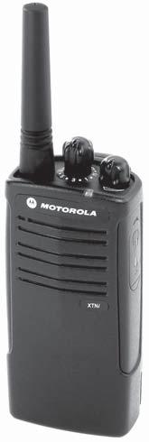
10 RADIO OVERVIEW PARTS OF THE RADIO Antenna Channel Selector Knob Microphone ON/ OFF/ Volume PTT (Push-to- Talk) Button LED Indicator SB1 - Monitor Button RADIO OVERVIEW Model Label Lithium-Ion Battery SB2 - Scan/ Nuisance Channel Delete 8
11 ON/OFF/Volume Knob Side Button 1 (SB1) Used to turn the radio ON or OFF and to adjust the radio s volume. Channel Selector Knob Used to switch the radio to different channels. Microphone Speaks clearly into the microphone when sending a message. Antenna The radio's antenna is non-removable. LED Indicator Used to give battery status, power-up status, radio call information and scan status Side Buttons Push-to-Talk (PTT) Button Press and hold down this button to talk, release it to listen. The Side Button 1 is a general button that can be configured by the Computer Programming Software - CPS. The default setting of SB1 button is Monitor. Side Button 2 (SB2) The Side Button 2 is a general button that can be configured by the CPS. The SB2 default setting is Scan/Nuisance Channel Delete. The Lithium-Ion (Li-Ion) Battery XTNi Series provides different types of batteries. For more information, see Battery Features and Charging Options on page 11. RADIO OVERVIEW 9
12 RADIO OVERVIEW This User Guide covers multiple XTNi Series models, and may detail some features your radio does not have. The model number of the radio is shown on the front of the radio, underneath the speaker, and tells you the following information: Model Frequency Band Transmit Power (Watts) Number of Channels Antenna XTNi PMR Non-removable 10
13 BATTERIES AND CHARGERS XTNi Series radios provide Lithium-Ion (Li- Ion) batteries that comes in different capacities that will define the battery life. It also offers the option to use Alkaline batteries.the radio comes equipped with a rapid charger. BATTERY FEATURES AND CHARGING OPTIONS About the Li-Ion Battery The XTNi radio series come equipped with a rechargeable Li-Ion battery. This battery should be charged before initial use to ensure optimum capacity and performance. Battery life is determined by several factors. Among the more critical are the regular overcharge of batteries and the average depth of discharge with each cycle. Typically, the greater the overcharge and the deeper the average discharge, the fewer cycles a battery will last. For example, a battery which is overcharged and discharged 100% several times a day, lasts fewer cycles than a battery that receives less of an overcharge and is discharged to 50% per day. Further, a battery which receives minimal overcharging and averages only 25% discharge, lasts even longer. Motorola batteries are designed specifically to be used with a Motorola charger and vice versa. Charging in non-motorola equipment may lead to battery damage and void the battery warranty. The battery should be at about 77 F (25 C) (room temperature), whenever possible. Charging a cold battery (below 50 F [10 C]) may result in leakage of electrolyte and ultimately in failure of the battery. Charging a hot battery (above 95 F [35 C]) results in reduced discharge capacity, affecting the performance of the radio. Motorola rapid-rate battery chargers contain a temperature-sensing circuit to ensure that batteries are charged within the temperature limits stated above. BATTERIES AND CHARGERS 11
14 BATTERIES AND CHARGERS Battery Recycling and Disposal Li-Ion rechargeable batteries can be recycled. However, recycling facilities may not be available in all areas. Under various U.S. state laws and the laws of several other countries, batteries must be recycled and cannot be disposed of in landfills or incinerators. Contact your local waste management agency for specific requirements and information in your area. Motorola fully endorses and encourages the recycling of Li-Ion batteries. In the U.S. and Canada, Motorola participates in the nationwide Rechargeable Battery Recycling Corporation (RBRC) program for Li-Ion battery collection and recycling. Many retailers and dealers participate in this program. For the location of the drop-off facility closest to you, access RBRC's Internet web site at or call BATTERY. This internet site and telephone number also provides other useful information concerning recycling options for consumers, businesses and governmental agencies. 12
15 Installing the Lithium-Ion (Li-Ion) Battery Removing the Lithium-Ion (Li-Ion) Battery battery latch battery latch BATTERIES AND CHARGERS slots 1. Turn OFF the radio. 2. With the Motorola logo side up on the battery pack, fit the tabs at the bottom of the battery into the slots at the bottom of the radio s body. 3. Press the top part of the battery towards the radio until a click is heard. Note: To learn about the Li-Ion Battery Life features, refer to About the Li-Ion Battery on page Turn OFF the radio. 2. Push down the battery latch and hold it depressed while removing the battery. 3. Pull the battery away from the radio. 13
16 Alkaline battery pack (optional accessory) Removing Alkaline Batteries BATTERIES AND CHARGERS Installing Alkaline Battery Pack Alkaline Battery Door Alkaline Battery Door 1. Turn OFF the radio, if it is turned on. 2. Remove Li-Ion battery 3. Assemble alkaline battery pack (optional accessory) in the same steps as installing the Li- Ion battery pack. 4. Remove battery door from alkaline battery pack. 5. Slide the 5 AA alkaline batteries into the frame, matching the markings inside the compartment. 1. Turn OFF the radio, if it is turned on. 2. Slide the battery latches, on both sides of the battery, downwards. 3. Pull the top of the battery away from the radio s body, and lift the battery from the radio s body. 14
17 Power Supply, Adaptors and Drop-in Tray Charger Adaptor Adaptor BATTERIES AND CHARGERS Power Supply Drop-in Tray Charger Your radio comes with one Drop-in Tray Charger, one Power Supply (also known as Transformer) and a set of adaptors. Your power supply, has a switchable capability which allows to suit any of the adaptors that comes with your radio package. The adaptor you should choose to install depends on the region you're located. Once you have identified the adaptor that matches your electrical outlet, proceed to install it as follows: Power Supply Power Supply Install Remove Slide down the adaptor grooves into the power supply until it snaps into place. Slide the adaptor upward to remove. Note: The adaptor shown in the pictures are just for illustration purposes. The adaptor you should install may be different. 15
18 Installing Spring Action Belt Clip Battery Life Information BATTERIES AND CHARGERS belt clip tab spring action belt clip Li-Ion Battery Life Depending on the radio model and/or region the battery capacity will be different. This feature will determine the estimated battery life. When the Battery Save feature is ON (enabled by default) the battery life will be longer. The following chart summarizes battery life estimations: Li-Ion Battery Life with Battery Save feature ON 1. Slide the spring action belt clip rails into the belt clip grooves on the back of the battery pack and slide it down until the belt clip tab snaps into place. 2. To remove, pull back the metal release tab on the belt clip tab and push the spring action belt clip upward to remove. Battery 0.5 Watt Standard 16 hours High Capacity 32 hours Note: Battery life is estimated based on 5% transmit/ 5% receive/ 90% standby standard duty cycle. 16
19 Alkaline Battery Life Charging the Battery The following chart provides estimations about the Battery Life using the Alkaline Batteries: Alkaline Battery Life Battery Save Feature ON 0.5 Watt 37 hours To charge the battery (with the radio attached), place it in a Motorola-approved Drop-in Tray Single Unit Charger or Drop-in Tray Multi-Unit Charger. Charging with the Drop-in Tray Single Unit Charger BATTERIES AND CHARGERS Note: Battery life are being estimated based on 5% transmit/ 5% receive/ 90% standby standard duty cycle. Power Supply (Transformer) Drop-in Tray Charger Port Drop-in Tray Charger 1. Place the drop-in tray charger on a flat surface. 2. Insert the connector of the power supply into the port on the side of the drop-in tray charger. 3. Plug the AC adaptor into a power outlet. 4. Insert the radio into the tray with the front of the 17
20 BATTERIES AND CHARGERS radio facing the front of the charger, as shown. Note: When charging a battery attached to a radio, turn the radio OFF to ensure a full charge. See Operational Safety Guidelines on page 7 for more information. Charging a Stand-alone Battery Important: Ensure that the bracket in the charger is adjusted to the correct position for either Standard or High-capacity battery. See Charging a Standard Battery on page 18. Charging a Standard Battery The drop-in tray charger has a removable bracket that is adjustable depending on the type of battery that needs to be charged. It is designed to charge either the battery (with the radio) or a standalone battery. The drop-in tray charger comes by default set up to charge a standard battery. The following image on page page 19 shows the orientation for each battery: To charge a battery whilst not attached to the radio - at step 4 above, insert the battery into the tray, with the inside surface of the battery facing the front of the charger, as shown. Ensure the slots in the battery correctly engage in the charger. 18
21 Identifying the Drop-In Charger s Position Before Charging Battery Adjustable bracket Adjustable bracket BATTERIES AND CHARGERS Standard High and Ultra High Capacity 19
22 Charging a High Capacity Battery BATTERIES AND CHARGERS Removable Piece Removable Piece Turn around horizontal 180 degree To convert the charger from the default setup to accommodate the high capacity: 1. Squeeze both tabs on each side of the removable bracket in the drop-in charger tray carefully and lift the bracket from the charger tray. 2. Rotate the removable bracket 180 degrees and replace it by fitting it in the charger slot until it clicks. The label on the removable bracket should show High & Ultra Capacity Battery facing front of the charger. 3. Repeat same procedure to return position back to charging a Standard Battery. Label on the removable bracket should show Standard Battery facing front. Note: Make sure the bracket is assembled correctly for both standalone battery and battery (with radio) to be properly charged. 20
23 Drop-in Tray Charger LED Indicators Standard Charger LED Indicator Status LED Status Comments Power ON Steady red indication for 3 seconds The charger has powered up Charging Blinking red (slow) The charger is currently charging Charging Complete Steady red indication Battery is fully charged Battery Fault(*) Blinking red (fast) Battery had a fault when battery was inserted Notes: (*) Normally re-seating the battery pack will correct this issue. (**) Battery temperature is too warm or too cold or wrong power supply is being used BATTERIES AND CHARGERS Rapid Charger LED Indicator Status LED Status Comments Power ON Steady green indication for 3 seconds The charger has powered up Charging Blinking green The charger is currently charging Top-off Charging Blinking green (slow) Battery is near fully charged Charge Complete Steady green indication Battery is fully charged Battery Fault (*) Blinking red (fast) Battery has a fault when battery was inserted Waiting to Charge (**) Double-blink yellow indications Battery charging conditions not suitable Notes: (*) Normally re-seating the battery pack will correct this issue. (**) Battery temperature is too warm or too cold or wrong power supply is being used 21
24 Estimated Charging Time BATTERIES AND CHARGERS The following table gives the estimated times to charge the battery. For further details, see Accessories on page 58. Estimated Charging Time Charging Solution Rapid Charging Solution Battery Capacity Standard High 1.5 hours 3 hours 22
25 Charging a Radio and Battery Using a Multi- Unit Charger-MUC (Optional Accessory) The Multi-Unit Charger (MUC) allows drop-in charging of up to 6 radios or batteries. Batteries can be charged with the radios or removed and placed in the MUC separately. Each of the 6 charging pockets can hold a radio or battery, but not both. 1. Place the charger on a flat surface. 2. Insert the power cord plug into the jack on the MUC. 3. Plug the cord into an AC outlet. 4. Turn the radio OFF. 5. Set removable bracket for battery type. 6. Insert the radio or battery into the charging pocket. Notes: This Multi-Unit Charger will also allow you to clone up to 3 radios (3 Source radios and 3 Target radios). When cloning, the MUC does not need to be plugged into a power source, but all radios require charged batteries. Further details on MUC s operation are explained in the Instructions Sheet provided with the MUC. Refer to the Accessories section to identify the part number for ordering the MUC. MUC LED Indicator Status LED Status Comments Charging Charge Complete Battery Fault (*) Steady Red Indication Steady Green Indication Red Fast blinking The charger is currently charging Battery is fully charged Battery had a fault when battery was inserted (*) Normally re-seating the battery pack will correct this issue. BATTERIES AND CHARGERS 23
26 GETTING STARTED GETTING STARTED For the following explanations, refer to page 8 of the user guide. TURNING RADIO ON/OFF To turn ON the radio, rotate the ON/OFF/ Volume Knob clockwise. The radio will chirp and the LED will briefly blink red. To turn the radio OFF, rotate the ON/OFF/ Volume Knob counterclockwise until you hear a click and the radio LED indicator turns OFF. ADJUSTING VOLUME Turn the ON/OFF/Volume Knob clockwise to increase the volume, or counterclockwise to decrease the volume. Note: Do not hold the radio too close to the ear when it is at a high volume setting or when adjusting the volume setting. SELECTING A CHANNEL To select a channel, rotate the Channel Selector Knob and select the desired channel number. Program each channel separately. Each channel has its own Frequency, Interference Eliminator Code and Scan Settings. TALKING AND MONITORING It is important to monitor for traffic before transmitting to avoid talking over someone who is already transmitting To monitor, press and hold the SB1(*) button for 2 to 3 seconds to access channel traffic. If no activity is present, you will hear static. To release, press SB1 again. Once channel traffic has cleared, proceed with your call by pressing the PTT button. When transmitting, the radio LED will blink red every 3 seconds. (*) This assumes SB1 has not been programmed for a different mode. 24
27 RECEIVING A CALL TALK RANGE 1. Select a channel by rotating the Channel Selector Knob until you reach the desired channel. 2. Make sure the PTT button is released and listen for voice activity. 3. The LED indicator blinks RED while the radio is receiving a call. 4. To respond, hold the radio vertically 1 to 2 inches (2.5 to 5cm) from mouth. Press the PTT button to talk; release it to listen. Note: Note: Please notice that when radio is receiving or transmitting, LED is always RED. In order to listen to all activity on a current channel, short press the SB1 to set the CTCSS/DPL code to 0. This feature is called CTCSS/DPL Defeat (Squelch set to SILENT). XTNi radios have been designed to maximize performance and improve transmission range in the field. It is recommended that you do not use the radios closer than 1.5 meters apart, to avoid interference. Talk range depends on the terrain. It will be affected by concrete structures, heavy foliage and by operating radios indoors or in vehicles. Optimal range occurs in flat, open areas with up to 9 kilometres of coverage. Medium range occurs when buildings and trees are in the way. Minimal range occurs when dense foliage and mountains obstruct the communication path. To establish a proper two-way communication, the channel, frequency, and interference eliminator codes must be the same on both radios. This depends on the stored profile that has been preprogrammed on the radio: GETTING STARTED 25
28 GETTING STARTED 1. Channel: Current channel that the radio is using, depending upon radio model. 2. Frequency: The frequency the radio uses to transmit/receive. 3. Interference Eliminator Code: These codes help minimize interference by providing a choice of code combinations. 4. Scramble Code: Codes that make the transmissions sound garbled to anyone listening who is not set to that specific code. 5. Bandwidth: Some frequencies have selectable channel spacing, which must match other radios for optimum audio quality. For details of how to set up frequencies and CTCSS/DPL codes in the channels, refer to Programming Mode on page 31. Note: Interference Eliminator Codes are referred also as CTCSS/DPL codes or PL/DPL codes 26
29 RADIO LED INDICATORS RADIO STATUS LED INDICATION Channel Alias Edit Channel Busy Cloning Mode Cloning In Progress Fatal Error at Power up Low Battery Low Battery Shutdown Monitor Power-Up Idle Programming Mode / Channel Mode Scan Mode Transmit (Tx)/Receive (RX) Note: Red heartbeat Solid orange Two orange heartbeats Solid orange One green blink, one orange blink, one green blink, then repeat for 4 seconds Orange blink Orange heartbeat LED is OFF Solid red for 2 seconds Green heartbeat Red heartbeat) Red heartbeat Channel Alias Edit only applies to Display Models GETTING STARTED 27
30 HANDS-FREE USE/VOX usethe CPS (Computer Programming Software) to make sure the VOX level is set to a level different from "0". Then, perform the following steps: 1. Turn radio OFF. 2. Open accessory cover. GETTING STARTED Motorola XTNi radios can operate handsfree (VOX) when used with compatible VOX accessories. A short delay occurs between talking and the radio transmission. With Compatible VOX Accessories The default factory setting for VOX sensitivity level is OFF (level 0 ). Before using VOX, 3. Insert plug of audio accessory firmly into accessory port. 4. Turn radio ON. Radio LED will blink double red 5. Lower radio volume BEFORE placing accessory near ear. 6. To transmit, speak into accessory microphone and to receive, stop talking. 7. VOX can be temporarily disabled by pressing the PTT button or by removing the audio accessory. Note: To order accessories, contact your Motorola dealer. 28
31 Hands Free without Accessories (ivox) Enable ivox by pressing the PTT button while turning the radio ON. Default value is OFF (level 0). If you want touse the VOX feature, VOX level should be set at a level different from 0. ivox operation can be temporarily disabled by pressing PTT. A short press of the PTT button will reenable ivox. There is a short delay between when talking and the radio transmission. Note: The ivox feature is only available on XTNId (Display model). Setting VOX Sensitivity The sensitivity of the radio's accessory or microphone can be adjusted during VOX operation to suit different operating environments. VOX/iVOX sensitivity can be programmed via the CPS. 1 = Low sensitivity 2 = Medium sensitivity 3 = High sensitivity Microphone Gain The sensitivity of the radio's microphone can be adjusted to fit different users or operating environments. This feature can be adjusted only through the CPS. Microphone default setting is set to level 2 (Medium gain). Battery Save Battery Save feature extends battery life as your radio goes into Idle state each time there is no radio activity. To enable/disable press SB1 and SB2 buttons simultaneously for 2 or 3 GETTING STARTED 29
32 seconds while powering up the radio until you hear a quick series of beeps. To have a slightly better attack time, set Battery Save feature to OFF so that the radio is always ready to transmit or receive without any delays. Note: Battery Save feature is set to ON by default Reset To Factory Defaults GETTING STARTED Reset To Factory Defaults will set back all radio features to the original factory default settings. To do so press PTT, SB2 and SB1 simultaneously while turning ON the radio until you hear a high tone chirp beep. End of Transmission Tone (Roger Beep Tone) Short press the SB1 button while turning ON the radio to enable/disable End of Transmission Tone. Note: By default, this feature is OFF. 30
33 PROGRAMMING FEATURES To easily program all the features in your radio, it is recommended to use the CPS Kit which includes the Programming Cable, CPS and accessories sections. Programming Mode Programming Mode is special radio mode that allows you to program basic radio's features by using the radio s panel programming. When the radio is set to Programming Mode, you are able to read and modify three features: Frequencies, Codes (CTCSS/DPL) and, Auto-scan. The Programming Frequencies feature allows you to select frequencies for each channel. The Interference Eliminator Code (CTCSS/ DPL) helps minimize interference by providing you with a choice of code combinations that filter out static, noise, and unwanted messages. The Auto Scan feature allows you to set a particular channel to automatically enable scan each time you switch to that channel ( you will not need to press any button to start scanning). Learning To Read The Values The Radio Signals You As the non-display model does not have a display to show the values that are being programmed, the radio will communicate this information using beeps and LED indications. The radio's LEDs will blink two colors: 'orange' to signal '0' and red for other values from '1' to '9'. Short and long red blinks differentiate the specific number the radio is showing you. As the radio blinks the number, it will generate a combination of short and long beeps. PROGRAMMING FEATURES 31
34 PROGRAMMING FEATURES Table 1: Programming Mode: Reading your Radio's Features Values Number Confirmation Beep LED Indication 0 Zero beep One short orange blink 1 One beep One short red blink 2 Two beeps Two short red blinks 3 Three beeps Three short red blinks 4 Four beeps Four short red blinks 5 Long beep One long red blink 6 Long beep and one beep One long and one short red blinks 7 Long beep and two beeps One long and two short red blinks 8 Long beep and three beeps One long and three short red blinks 9 Long beep and four beeps One long and four short red blinks 32
35 Frequencies PROGRAMMING MODE 1 2 CTCSS/DPL First Digit PTT Second Digit PTT First Digit PTT Second Digit PTT Third Digit PTT Long PTT Long PTT 3 PTT Enter Programming Mode (PTT + SB1 + Turn ON radio) Idle Programming Mode PTT Roll Over key chirp Auto-Scan ON/ OFF Exit Long PTT Figure 1 Entering Programming Mode PROGRAMMING FEATURES 33
36 PROGRAMMING FEATURES Entering Programming Mode Note: Before programming the features, make sure your radio is set to the channel you wish to program. You can do so before entering Programming Mode or at any time during the Programming Mode by turning the Channel Selector Knob to the desired channel. To read or modify frequencies, codes and auto-scan, set the radio to 'Programming Mode' by long pressing both the PTT and the SB1 button simultaneously while turning ON the radio for 3 to 5 seconds until a chirp sounds to indicate that you have entered 'Idle' Programming Mode (*).The radio LED will start blinking a green heartbeat. Note: (*)'Idle' Programming Mode is the stage of the Programming Mode in which the radio is waiting for the user to start the radio programming cycle (refer to the Programming Mode picture above). Once you are in the 'Idle' Programming Mode, you will be able to read the radio frequencies, codes and auto-scan setting by short pressing the PTT button to move along the different programmable features. Reading Frequencies Values When reading frequencies values you need to read two digits as XTNi series radios have 16(*) frequencies for UHF (refer to UHF Frequencies tables). Once in Idle Programming Mode, the radio will signal the first value it was programmed when you short press the PTT button (see picture below). This value corresponds to the frequency's first digit value. If you short press the PTT button again, the radio will signal you the second digit value. 34
37 1 Frequencies First PTT Second PTT Digit Digit Reading CTCSS/DPL Values The following is an example of the order in which your radio will be signaling the 118 CTCSS/DPL code: : First Digit Third Digit If you continue short pressing the PTT button, as shown in the Entering Programming Mode on page 33 (Stage 2) the radio will move forward to programming CTCSS/PL Codes. When reading the values for CTCSS/PL Codes the radio signals you the digit codes each time you short press the PTT button. You will have to read three digits as XTNi Series have up to 122 codes available (refer to Frequencies and Codes Charts Section). Second Digit Example of how to program values Short press the PTT button. The radio will signal you the first digit 1, short press PTT button again and the radio will show the second digit 1 and finally, short press PTT again and radio will show the third digit 8. PROGRAMMING FEATURES 35
38 PROGRAMMING FEATURES Reading Auto-Scan Values After finishing reading CTCSS/DPL codes, if you short press PTT once again, the radio will take you to Auto-Scan ( Entering Programming Mode on page 33 (stage 3) Auto-Scan only has two values: If the radio signals the value... Note: 0 OFF 1 ON It means Auto- Scan is... AutoScan is set to OFF by default. Note that while in Auto-Scan Mode, if you short press PTT button, the radio will return to the Idle Programming Mode. It will then generate a roll-over chirp and it will start blinking a green heartbeat. Programming Frequencies, Codes and Auto-Scan Each time your radio signals and beeps, you can change the current setting value by either increasing it by short pressing SB1 or decreasing it by short pressing SB2. The radio will then signal the new setting it has been programmed to. Saving Settings If you are satisfied with the new setting, you can either: short press PTT to continue programming, long press PTT to save and return to 'Idle' Programming Mode, or long press the PTT button twice to exit 'Idle' Programming Mode and return to the normal radio operation. 36
39 Notes: If you don't want to save the value you just programmed, turn radio OFF or change channel using the channel knob. If you roll-over to the beginning at Idle Programming Mode you will hear a chirp and radio LED will start blinking green again. All values that were changed will be automatically saved. Programming Mode FAQ 1. I got distracted while programming and forgot which digit I was programming. What should I do? Return to 'Idle' Programming Mode and start over, as you will not be able to go back into the Programming Mode (the radio does not provide further way to let you know the specific stage you are when programming). Therefore you can: Long press the PTT button. The radio will return to the 'Idle' Programming Mode or, Turn OFF the radio and enter Programming Mode again (see instructions in the beginning of this section) 2. I am trying to program a frequency (or code) value but the radio would not do it. It rolled over and took me back to value 0. The radio will not allow you to program any values that are not available in the frequencies and codes pool. For example, if you try to program code 128, the radio would not accept it, as the maximum value allowed is 122. Same thing will happen with frequencies. Check the Frequencies and Codes Charts section to make sure you are programming a valid number. 3. I am trying to enter the Programming Mode but the radio would not do it. The radio might be locked using the CPS for not allowing Front-Panel Programming. To reenable, use the CPS. PROGRAMMING FEATURES 37
40 PROGRAMMING FEATURES 4. When I was programming I made a mistake and program the wrong value. How can I erase it or re-program it? If you make a mistake while programming a value you have two choices: a) The radio roll-over (and generates a 'wraparound' sound) each time it reaches a maximum (9) or minimum (0) value. Keep increasing (short press SB1) or decreasing (short pressing SB2) until you get the desired value or, b) Turn OFF the radio and start-over. 5. I just programmed the value I wanted. How do I exit Programming Mode? If you are in Programming Mode you can exit by long pressing the PTT button twice. If you are already in the Idle Programming Mode, long press the PTT button once. 6. I am done programming the features in this channel and want to program another channel. Switch to the new channel you wish to program by using the Channel Selector Knob. The radio will go into to the 'Idle' Programming Mode. If you wish to save the changes, make sure you are in the Idle Programming Mode before switching the channel as otherwise you will lose changes made. PROGRAMMING VALUES EXAMPLE Example of Programming a Frequency Assuming current frequency value is set up to channel 1, with the UHF default frequency 02 (equivalent to Mhz), and you want to change it to Frequency Number = 13 (which is mapped to Mhz), follow this sequence: Enter Programming Mode 38
41 Short press the PTT button to enter Frequency Mode. Radio will signal current value 0 (orange blink) Press the SB1 button once to increase first digit to 1. Short press the PTT button once to move ahead and program the frequency s second digit. Radio will signal current value which is 2 (two red blinks). Press the SB1 button to increase the digit value to 3. Long press the PTT button. LED indicator will show a green heartbeat to indicate 'Idle' state. Long press the PTT button to exit Programming Mode or turn radio OFF. Example of Programming a Code Assuming current code value is set to factory default 001, and you want to change it to CTCSS/DPL Code = 103 follow the sequence below: Enter Programming Mode Short press the PTT button three times (Enter CTCSS/DPL Programming Selection Mode). Radio LED will blink orange to indicate that current value is 0 Press the SB1 button once (to change first digit to 1 ) LED indicator will blink red. Short press the PTT button (to move forward and program second digit). Radio LED will blink orange to indicate current value is 0. Short press the PTT button and move ahead to program the third digit. LED indicator will blink red to indicate current value is 1. Press the SB1 button to change the third digit to 2. Press the SB1 button to change again this third digit to 3. Radio will signal the chosen value. Long press the PTT button to save changes and return to 'Idle' Programming Mode. Once in 'Idle' Programming Mode, LED indicator will start blinking a green heartbeat. Long press the PTT button to exit Programming Mode. PROGRAMMING FEATURES 39
42 PROGRAMMING FEATURES Example of Programming Auto Scan Auto-Scan is the last Programming Mode and can be set to "ON" or "OFF" on a particular channel. To set Auto Scan to ON : 1. Enter Programming Mode and select the desired channel (see "Entering Programming Mode" picture in page 38). 2. Short press the PTT button six times to enter Auto Scan Programming Selection Mode. The radio will signal beeps and will show the current Auto Scan setting (please refer to "Reading Auto-scan Settings" in page 41). 3. Short press the SB1 button to toggle ON/ OFF the auto-scan feature in the channel. When ON radio LED will blink RED once. When OFF radio LED will blink ORANGE once. OTHER PROGRAMMING FEATURES SCAN Scan allows you to monitor other channels in order to detect conversations. When the radio detects a transmission, it will stop scanning and will stay on the active channel. This will allow you to listen and talk to the people on that stopped channel without having to change the channel knob. If there is talking going on channel 2 during this time, the radio will stay on channel 1 and you will not hear channel 2. After talking has stopped in channel 1, the radio will wait 5 seconds before resuming scan again. To start scanning, press the SB2 button (*). When the radio detects channel activity, it will stops on that channel until the activity ends. You can talk to the person(s) transmitting without having to switch channels by pressing PTT. To stop scanning, short press the SB2 button again. By pressing the PTT button while the radio is 40
43 scanning, the radio will transmit on the channel which was selected before Scan was activated. If no transmission occurs within five seconds, scanning will resume. If you want to scan a channel without Interference Eliminator Codes (CTCSS/DPL), set the code settings for the channels to 0 in the CTCSS/DPL Programming Selection Mode. Whenever the radio is set up in Scan, the LED will signal a red blink. Note: (*)Assumes the SB2 button is not programmed to other function different from the default. If Auto-Scan has been enabled for a particular channel, do not press SB2 to scan the channel, as the radio will do it automatically. Editing Scan List Scan Lists can be edited by using the CPS (refer to CPS (Computer Programming Software) on page 42. Nuisance Channel Delete Nuisance Channel Delete allows you to temporarily remove channels from the Scan List. This feature is useful when irrelevant conversations on a nuisance channel tie up the radio's scanning feature. To delete a channel from the scan list: Start Scanning by short pressing the SB2 button(*) Wait until the radio stops on the channel you wish to eliminate, then long press the SB2 button to delete it. The channel will not be removed until you exit Scan by short pressing the SB2 button again or by turning the radio OFF. Note: (*) Assumes the SB2 button is not programmed to another function different from the default. PROGRAMMING FEATURES 41
44 PROGRAMMING FEATURES CPS (COMPUTER PROGRAMMING SOFTWARE) Drop-in Charger Tray Mini-connector Radio to be programmed USB Connector CPS Programming Cable CPS Software The easiest way to program or change features in your radio is by using the Computer Programming Software (CPS) and the CPS Programming Cable(*). To do so, connect the XTNi radio via the Dropin Charger Tray and CPS Programming Cable as shown in the picture above. The CPS allows the user to program frequencies, PL/DPL codes, as well as other features such as: Direct Frequency Input, Repeater/Talkaround, Bandwidth Select, Timeout Timer, Power Select, Battery Type Select, Scan List, Call Tones, Scramble, Reverse Burst etc. CPS is a very useful tool as it can also lock the frontpanel radio programming or restrict any specific radio feature to be changed (to avoid preset radio values to be accidentally erased). It also provides security by giving the option to set up a password for profile radio's management. Please refer to Features Summary Chart Section at the end of the User's Guide for more details. Note: Features should be enabled by an Authorized Motorola Dealer. Contact your Motorola Point of Purchase for details Note: (*) CPS Programming Cable is an accessory sold separately. For part number information refer to the Accessories Section. 42
45 Bandwidth Select Scramble Default setting for Bandwidth Select is 12.5 KHz. Some frequencies have selectable channel spacing, which must match other radios for optimum audio quality. Time-Out Timer When pressing PTT buttons, transmissions can be terminated by setting up a Time-Out Timer. The radio can be programmed to turn the radio OFF in either 60, 120 or 180 seconds. Battery Type Setting The XTNi radio can be powered by either Alkaline or Lithium-Ion batteries. Call Tones Call Tones enable you to transmit to other radios in your group by alerting them that you are about to talk or alerting them without speaking. The Scramble feature makes transmissions sound garbled to anyone listening without the same code. Scramble default value is OFF. Note: Some of the features available with the CPS software may vary depending on the radio model. Reverse Burst Reverse Burst eliminates unwanted noise (squelch tail) during loss of carrier detection. Can select values 180/240. Notes: The features described in previous pages are just some of the features CPS has. CPS offers more capabilities. For more information please refer to the HELP file in the CPS. Some of the features available with the CPS software may vary depending on the radio model. PROGRAMMING FEATURES 43
46 PROGRAMMING FEATURES CLONING RADIOS You can copy XTNi Series radio profiles from one Source radio to a Target radio by using any of these 3 methods: 1. One Multi Unit Charger (optional accessory) 2. Two single unit chargers and a Radio-to- Radio cloning cable (optional accessory) 3. the CPS Cloning with a Multi-Unit Charger (MUC) To clone radios using the MUC, there must be at least two radios: a Source radio(radio to be cloned or copied) and a Target radio (radio which profile will be changed to be the same as the source radio.) The Source radio has to be in Pocket 1, 3 or 5 while the Target radio to be cloned has to be in Pockets 2, 4 or 6, matching the MUC s pockets by pairs as follows: 1 and 2 or 3 and 4 or 5 and 6. When cloning, the MUC does not need to be plugged into a power source, but ALL radios require charged batteries. Follow these steps for cloning: 1. Turn ON the Target radio and place it into one of the MUC Target Pockets 2. Power the Source radio following the sequence below: - Long press the PTT button and SB2 simultaneously while turning the radio ON. - Wait for 3 seconds before releasing the buttons until a distinctive audible tone is heard. 3. Place the Source radio in the source pocket that pairs with the target pocket you chose in step 1. 44
47 Press and release SB1. 4. After cloning is completed, the Source radio will sound either a pass tone (cloning was successful) or a fail tone (cloning process has failed). The pass tone sounds like a good key chirp whereas the fail tone sounds similar to a bonk tone. If the Source radio is a display model, it will either show Pass or Fail on the display (a tone will be heard within 5 seconds). 5. Once you have completed the cloning process, turn the radios OFF and ON to exit the cloning mode. If cloning fails please refer to What to do if cloning fails on page 47. Further details on how to clone units are explained in the instructions sheet provided with the MUC.! W A R N I N G Paired Target radios and Source Readios must be of the same type in order for the cloning to run successfully. Cloning Radio using the Radio to Radio (R2R) Cloning Cable (optional accessory) When ordering the MUC See Chargers on page 59 for the MUC part number. Note: (*) MUC pockets numbers should be readfrom left to right with the Motorola logo facing front. PROGRAMMING FEATURES 45
48 PROGRAMMING FEATURES Operating Instructions 1. Before beginning the cloning process, make sure you have: A fully charged battery on each one of the radios. Two Single Unit Chargers (SUC). Turned OFF the radios and, Both radios are of the same radio model. 2. Unplug any cables (power supply or USB cables) from the SUCs. 3. Plug one side of the cloning cable mini connector to one SUC. Plug the other end to the second SUC. Note: During the cloning process no power is being applied to the SUC. The batteries will not be charged. A data communication is being established between the two radios. 4. Turn ON the Target radio and place it into one of the SUCs. 5. On the Source radio, power the radio following the sequence below: Long press the PTT button and SB2 simaltaneously while turning the radio ON. Wait for 3 seconds before releasing the buttons until a distinctive audible tone is heard. 6. Place the Source radio in its SUC, press and release SB1. 7. After cloning is completed, the Source radio will sound either a pass tone (cloning was successful) or a fail tone (cloning process has failed). The pass tone sounds like a good key chirp whereas the fail tone sounds similar to a bonk tone. If the Source radio is a display model it will either show Pass or Fail on the display (a tone will be heard in no more than 5 seconds). 8. Once you have completed the cloning process, turn the radios OFF and ON in order to exit clone mode. 46
49 What to do if cloning fails The radio will emit an audible bonk indicating that the cloning process has failed. In the event that cloning fails, try performing each of the following before trying to start the cloning process again: Attention: This cloning cable is designed to operate only with compatible Motorola RLN6170 (Rapid) Single Unit Charger. When ordering Cloning Cable please refer to P/N RLN6303. For details about accessories refer to Accessories section. 1. Ensure that the batteries on both radios are fully charged. 2. Check the cloning cable connection on both SUCs. 3. Ensure that the battery is engaged properly on to the radio. 4. Ensure that there is no debris in the charging tray or on the radio contacts. 5. Ensure that the Source radio is in cloning mode. 6. Ensure that the Target radio is turned ON. 7. Ensure both radios are both from the same type. (same frequency band, same front panel (display/non display), same region and same transmission power). Cloning using the CPS (Computer Programming Software) When cloning using this method, you will need to have the CPS software, a Drop-in Tray Charger and the CPS Programming Cable. Information on how to clone using the CPS is available either in the CPS Help File --> Content and Index --> Cloning Radios or in the CPS Programming Cable Accessory Leaflet. Note: (*) CPS Programming Cable is an accessory sold separately. For part number information refer to the Accessories Section. PROGRAMMING FEATURES 47
50 TROUBLESHOOTING TROUBLESHOOTING No Power Symptom Hearing other noises or conversation on a channel Try This Recharge or replace the Li-Ion battery. Replace AA batteries. Extreme operating temperatures affect battery life. Refer to "About the Li- Ion Battery" on page 11. Confirm Interference Eliminator Code is set. Frequency or Interference Eliminator Code may be in use. Change settings: either change frequencies or codes on all radios. Make sure radio is at the right frequency and code when transmitting. Refer to ""Talking and Monitoring" on page 24. Message Scrambled Limited talk range Scramble Code might be ON, and/or setting does not match other radios' settings. Steel and/or concrete structures, heavy foliage, buildings or vehicles decrease range. Check for clear line of sight to improve transmission. Wearing radio close to body such as in a pocket or on a belt decreases range. Change location of radio. Refer to "Talking and Monitoring" on page
Two-Way Radios. Quick Start Guide. XT460 Display model
 Two-Way Radios Quick Start Guide XT460 Display model CONTENTS Contents..................................... 1 Safety....................................... 2 Batteries and Chargers Safety Information........
Two-Way Radios. User Guide. RMU2080 & RMV2080 Non-Display models
 Two-Way Radios User Guide RMU2080 & RMV2080 Non-Display models Open Source Software Legal Notices: This Motorola product contains Open Source Software. For information regarding licenses, acknowledgements,
RM Series /Séries RM Two-Way Radios Radios bidirectionnelles
 RM Series /Séries RM Two-Way Radios Radios bidirectionnelles User Guide Guide de l utilisateur en-us fr-ca Models RMU 2040, RMM2050 / Modèles RMU2043 Open Source Software Legal Notices: This Motorola product
Commercial Series. CP140 Portable Radio. User Guide
 Commercial Series CP140 Portable Radio User Guide Issue: October 2003 CONTENTS Computer Software Copyrights... 2 Radio Overview..... 3 Operation and Control Functions..... 3 Radio Controls.... 3 LED Indicator.....
CONTENTS CONTENTS. Safety Batteries and Chargers Safety Information 2 Operational Safety Guidelines...3. Introduction... 4 Package Contents...
 . CONTENTS Safety.............................. 1 Batteries and Chargers Safety Information 2 Operational Safety Guidelines.............3 Introduction......................... 4 Package Contents......................4
Professional Radio P040
 Professional Radio P040 User Guide 68P64110B67A Issue: April 2002 CONTENTS Radio Overview.................... 3 Parts of the Radio................... 3 On-Off/Volume Knob............... 4 Channel Selector
GP344R User Guide B98-B. English
 M GP344R User Guide 6864110B98-B M COMPUTER SOFTWARE COPYRIGHTS COMPUTER SOFTWARE COPYRIGHTS The Motorola products described in this manual may include copyrighted Motorola computer programs stored in
BASIC USER GUIDE BASIC USER GUIDE CONTENTS. GeneralInformation... 2
 GP360 GP360 1 2 7 8 12 3 4 5 9 10 11 13 6 CONTENTS GeneralInformation... 2 Operation and Control Functions..... 2 Radio Controls...................... 2 Audio Signal Tones.................. 3 Programmable
LSC Radio User Guide Information and Guidelines
 LSC Radio User Guide Information and Guidelines The following user guide applies to both the Motorola VL50 and CLS1410 Radio s. Below are guidelines established for usage. 1) Radios and headsets are to
Walkie-Talkie. User Manual and Instruction. Getting Started
 Walkie-Talkie User Manual and Instruction Getting Started Installing the AA Batteries Your radio uses 3 AA Alkaline batteries. 1. With the back of the radio facing you, lift the battery latch up to release
TLKR T60 OWNER'S MANUAL EN DE FR IT ES PR NL DA NO TU PL SV RU
 TLKR T60 OWNER'S MANUAL EN DE FR IT ES PR NL DA NO TU PL SV RU SF 1 PRODUCT SAFETY AND RF EXPOSURE FOR PORTABLE TWO-WAY RADIOS! Caution ATTENTION! Before using this product, read the RF energy awareness
GD
 PROFESSIONAL DIGITAL TWO-WAY RADIO MOTOTRBO DP4000/DP4000e SERIES PORTABLE RADIOS QUICK REFERENCE GUIDE en-us JULY 2017 2017 Motorola Solutions, Inc. All rights reserved. @68012007019@ 68012007019-GD English
BE
 PROFESSIONAL DIGITAL TWO-WAY RADIO MOTOTRBO DP3441/DP3441e, DP3661e SERIES PORTABLE RADIOS QUICK REFERENCE GUIDE en-us JULY 2017 2017 Motorola Solutions, Inc. All rights reserved. @68012009021@ 68012009021-BE
Talkabout T82/ T82 EXTREME OWNER S MANUAL
 Talkabout T82/ T82 EXTREME OWNER S MANUAL B RF ENERGY EXPOSURE AND PRODUCT SAFETY GUIDE FOR PORTABLE TWO-WAY RADIOS ATTENTION! Before using this product, read the RF Energy Exposure and Product Safety
PROFESSIONAL DIGITAL TWO-WAY RADIO SYSTEM MOTOTRBO DP 3600/DP 3601 DISPLAY PORTABLE QUICK REFERENCE GUIDE
 PROFESSIONAL DIGITAL TWO-WAY RADIO SYSTEM MOTOTRBO DP 3600/DP 3601 DISPLAY PTABLE QUICK REFERENCE GUIDE m DP 3600/3601 Portables Quick Reference Guide Important Safety Information Product Safety and RF
User manual AWR-8000 / AWR Advanced Wireless Communications
 User manual AWR-8000 / AWR-8001 Advanced Wireless Communications THANK YOU! Thank you for your purchase of Advanced Wireless Communications AWR-8000 / AWR-8001 two-way radio. This portable two-way radio
PROFESSIONAL DIGITAL TWO-WAY RADIO SYSTEM MOTOTRBO DGP SERIES CONNECT PLUS NON-DISPLAY PORTABLE USER GUIDE
 PROFESSIONAL DIGITAL TWO-WAY RADIO SYSTEM MOTOTRBO DGP SERIES CONNECT PLUS NON-DISPLAY PORTABLE USER GUIDE Declaration of Conformity DECLARATION OF CONFORMITY Per FCC CFR 47 Part 2 Section 2.1077(a) Responsible
TWO-WAY RADIO MODEL CXR925
 Making Life Easier and Safer Owner s Manual Staying in touch with your family and friends is convenient and easy when using your microtalk radio. Some of the many uses you will discover include: Communicating
PROFESSIONAL DIGITAL TWO-WAY RADIOS MOTOTRBO TM DP1400 NON-DISPLAY PORTABLE USER GUIDE
 PROFESSIONAL DIGITAL TWO-WAY RADIOS MOTOTRBO TM DP1400 NON-DISPLAY PORTABLE USER GUIDE en de-de fr-fr it-it es-es tr pl ru ar-eg Contents This User Guide contains all the information you need to use the
XU/XV-100 Series User Manual
 XU/XV-100 Series User Manual This device complies with Part 15 of FCC Rules. Operation is subject to the following two conditions: This device may not cause harmful interference, and 2) This device must
DTR Frequently Asked Questions (FAQ) LEAFLET
 LEAFLET") DIGITAL TWO-WAY RADIO DTR Frequently Asked Questions (FAQ) LEAFLET April 2019 2019 Motorola Solutions, Inc. All rights reserved. *MN005512A01* MN005512A01-AA Contents Product Safety and RF Exposure Compliance...3
DIGITAL TWO-WAY RADIO DTR Frequently Asked Questions (FAQ) LEAFLET April 2019 2019 Motorola Solutions, Inc. All rights reserved. *MN005512A01* MN005512A01-AA Contents Product Safety and RF Exposure Compliance...3
OWNER S MANUAL FM HANDHELD TRANSCEIVER
 , OWNER S MANUAL RPU4200A FM HANDHELD TRANSCEIVER NOTE, OWNER S MANUAL RPU4200A FM HANDHELD TRANSCEIVER We are very grateful for your purchasing brand twoway radios produced by Relm Wireless Corporation.
MOTOROLA COMMERCIAL SERIES BASIC USER GUIDE CM140 & CM160
 MOTOROLA COMMERCIAL SERIES BASIC USER GUIDE CM140 & CM160 11 1 2 4 10 CHAN 34 P1 P2 P3 P4 11 8 3 5 6 7 10 9 English BASIC USER GUIDE Contents RadioOverview... 2 Radio Controls...................... 2 Microphone
Battery Informationy/Antenna and Other Accessories Charging the Battery
 Thank You Thank you for your purchase of HYT portable two-way radio. HYT portable radios will provide you with clear and reliable communications in high efficiency. Please read this manual before your
GETTING STARTED. Radio layout. LCD display with icons
 GETTING STARTED Radio layout LCD display with icons 1. Key lock button 2. Battery meter 3. Main channel indicator 4. Scan icon 5. Roger beep indicator 6. CTCSS sub-channel indicator 7. VOX indicator 1
DP 3600 / DP 3601 Display Portable
 Professional Digital Two-Way Radio System DP 3600 / DP 3601 Display Portable User Guide Contents This User Guide contains all the information you need to use the MOTOTRBO Series Portables. Important Safety
Headset Intercom System. Operating Instructions
 Headset Intercom System Model C1025 Operating Instructions Headset and Transceiver Pack Base Station Model C1025 Table of Contents Intended Use...iii FCC Information...iii Service...iii System Descriptions...1
TLKR T92 H2O OWNER'S MANUAL. it-it. nl-nl. fi-fi. pt-pt. nb-no tr-tr pl-pl ru-ru uk-ua
 TLKR T92 H2O OWNER'S MANUAL en de-de fr-fr it-it es-es pt-pt nl-nl da-dk sv-se fi-fi nb-no tr-tr pl-pl ru-ru uk-ua RF ENERGY EXPOSURE AND PRODUCT SAFETY GUIDE FOR PORTABLE TWO- WAY RADIOS ATTENTION! Before
Owner s Manual. Model G-223. GMRS/FRS Radio. FEATURES 22 Channels Scan 22 Key Pad Lock Call Alert Power HI/LO Roger Beep Tone
 Owner s Manual Model G-223 GMRS/FRS Radio FEATURES 22 Channels Scan 22 Key Pad Lock Call Alert Power HI/LO Roger Beep Tone This device complies with Part 15 of the FCC rules. Operation is subject to the
DC Instruction Manual. Professional FM Transceiver
 DC-1074 Professional FM Transceiver Instruction Manual Use of the citizen band radio service is licensed in Australia by ACMA Radiocommunications (Citizen Band Radio Stations) Class Licence and in New
PROFESSIONAL DIGITAL TWO-WAY RADIO SYSTEM. MOTOTRBO XiR M8220/ XiR M8228 NUMERIC DISPLAY MOBILE USER GUIDE
 PROFESSIONAL DIGITAL TWO-WAY RADIO SYSTEM MOTOTRBO XiR M8220/ XiR M8228 NUMERIC DISPLAY MOBILE USER GUIDE Contents This User Guide contains all the information you need to use the MOTOTRBO XiR Series
Owner s Manual For Models G-225 & G-227 GMRS/FRS Radio
 Owner s Manual For Models G-225 & G-227 GMRS/FRS Radio FEATURING 22 Channels 38 CTCSS codes VOX Monitor function Call Alert Back-Lit LCD Vibrate Alert (G-227 Only) Scan Roger Beep Tone This device complies
Pair of PMR446 Two-Way Personal Radios Model: TP391
 Pair of PMR446 Two-Way Personal Radios Model: TP391 USER MANUAL MANUALE D USO MANUEL DE L UTILISATEUR BEDIENUNGSANLEITUNG MANUAL DE USUARIO MANUAL DO USUÁRIO HANDLEIDING BRUKSANVISNING P/N:086L004722-016
T80/T80 EXTREME/T81 HUNTER
 T80/T80 EXTREME/T81 HUNTER OWNER'S MANUAL en pt-pt de-de fr-fr it-it es-es nl-nl da sv fi no-no hu pl ru uk RF ENERGY EXPOSURE AND PRODUCT SAFETY GUIDE FOR PORTABLE TWO- WAY RADIOS ATTENTION! Before using
TWO-WAY RADIO. Þ ß Ô ² ú RPV516/RPU416. Owner's Manual
 TM TWO-WAY RADIO Þ ß Ô ² ú RPV516/RPU416 Owner's Manual Thank you! We are grateful that you choose RELM for your land mobile applications. We believe this easyto-use transceiver will provide dependable
Greaval GV-8S. User Manual
 Greaval GV-8S User Manual Version 2017 A B C D E F G LED Indicator Lights red during transmit, green when receiving a signal Channel Switch Rotate to select a channel. No. 16 is the scanning channel Power
RELM Wireless Corporation
 RELM Wireless Corporation 1 THANK YOU Thank you for your purchase of the RELM two-way portable radio. This easy-to-use radio adopts the latest advanced technology, providing reliable communication performance
1. SAFETY INFORMATION
 1. SAFETY INFORMATION NOTE TO USER Illegal operation is punishable by fine, imprisonment or both. Refer service to Advanced Wireless Communications only. SAFETY It is important that the operator is aware
Instruction Manual. Model: TX-446. Tech Private Mobile Radio (PMR)446MHz
446MHz") Instruction Manual Tech Private Mobile Radio (PMR)446MHz Model: TX-446 TTI TECH CO., LTD. Eundo Bldg, 737-19, Banpo-1dong, Seocho-ku, Seoul, Korea, 137-041 http://www.ttikorea.co.kr TABLE OF CONTENTS 1.
Instruction Manual Tech Private Mobile Radio (PMR)446MHz Model: TX-446 TTI TECH CO., LTD. Eundo Bldg, 737-19, Banpo-1dong, Seocho-ku, Seoul, Korea, 137-041 http://www.ttikorea.co.kr TABLE OF CONTENTS 1.
INSTRUCTION MANUAL FM HANDHELD TRANSCEIVER
 INSTRUCTION MANUAL PT558 FM HANDHELD TRANSCEIVER NOTE INSTRUCTION MANUAL PT558 FM HANDHELD TRANSCEIVER We are very grateful for your purchasing brand twoway radios produced by Kirisun Electronics (Shenzhen)
Digital Portable Radio
 II TP620 Digital Portable Radio We are very grateful for your purchasing KIRISUN brand two-way radios produced by Kirisun Communications Co., Ltd. We believe KIRISUN two-way radio, which always incorporates
GM350 User Guide. GM350 User Guide. Safety Information. English
 GM350 User Guide GM350 User Guide Contents Page: Safety Information...1 General Information... 2 Radio Controls/Indicators... 2 Audio Signals... 3 Display Icons...3 Radio On/Off...3 Channel Selection...
UH45 Series. UHF CB Transceiver. For more exciting new products please visit our website: Australia:
 UH45 Series UHF CB Transceiver For more exciting new products please visit our website: Australia: www.uniden.com.au Controls & Indicators Included in your Package UH45 Series Radio Operating Guide Belt
PROFESSIONAL DIGITAL TWO-WAY RADIO SYSTEM MOTOTRBO DP 3400/DP 3401 NON-DISPLAY PORTABLE USER GUIDE
 PROFESSIONAL DIGITAL TWO-WAY RADIO SYSTEM MOTOTRBO DP 3400/DP 3401 NON-DISPLAY PTABLE USER GUIDE Contents This User Guide contains all the information you need to use the MOTOTRBO DP Series Digital Portable
RMV25 / RMV50 RMU25 / RMU45
 RMV25 / RMV50 RMU25 / RMU45 Owner's Manual TABLE OF CONTENTS INTRODUCTION... 3 FCC Requirements... 3 SAFETY WARNING INFORMATION... 3 CONTROLS and INDICATORS... 5 FRONT PANEL... 5 LCD Icons and Indicators...
SMARTNET /SMARTZONE TRUNKED. MOTOTRBO ATS 2500i XiR P8260/ XiR P8268 DISPLAY PORTABLE USER GUIDE
 SMARTNET /SMARTZONE TRUNKED MOTOTRBO ATS 2500i XiR P8260/ XiR P8268 DISPLAY PTABLE USER GUIDE Contents This User Guide contains all the information you need to use the MOTOTRBO XiR Series Portable Radios.
INSTRUCTION MANUAL VHF FM TRANSCEIVER TK-2206 UHF FM TRANSCEIVER TK-3206 B (M,M3 )
") INSTRUCTION MANUAL VHF FM TRANSCEIVER TK-2206 UHF FM TRANSCEIVER TK-3206 B62-1763-00 (M,M3 ) 09 08 07 06 05 04 03 02 01 00 THANK YOU We are grateful you chose KENWOOD for your land mobile radio applications.
INSTRUCTION MANUAL VHF FM TRANSCEIVER TK-2206 UHF FM TRANSCEIVER TK-3206 B62-1763-00 (M,M3 ) 09 08 07 06 05 04 03 02 01 00 THANK YOU We are grateful you chose KENWOOD for your land mobile radio applications.
9/14/2017. APX 4000 Portable Radio. Before You Begin. APX 4000: Introduction. Rensselaer County Bureau of Public Safety 800 MHz Radio User Training
 9/14/2017 Rensselaer County Bureau of Public Safety 800 MHz Radio User Training Portable Radio Before You Begin View the Operations Training Presentation first, it covers: Overview of Rensselaer County
ALAN 777 PMR 446 Radio Set User manual
 ALAN 777 PMR 446 Radio Set User manual The all new ALAN 777 represents the very latest and most advanced technology currently available on the PMR446 and LPD market. With its stylish lines and modern design,
Two-Way Radio Model MT 600
 Two-Way Radio Model MT 600 ENGLISH 1 10 9 2 3 4 1. Antenna 2. External Speaker/ Microphone/Charge Jack 3. Mode/Power Button 4. Lock Button 5. Channel Select Buttons 6. Speaker/Microphone 7. Light/Max Range
Model: TP380 User Manual
 Model: TP380 User Manual 1 UHF RADIO TRANSCEIVER MODEL: TP380 USER MANUAL INTRODUCTION Thank you for selecting the Oregon Scientific TP380 as your product of choice. This product is a portable, easy-to-use
UH043SX-2NB. UHF CB Transceiver. For more exciting new products please visit our website: Australia: New Zealand:
 UH043SX-2NB UHF CB Transceiver For more exciting new products please visit our website: Australia: www.uniden.com.au New Zealand: www.uniden.co.nz Controls & Indicators Included in your Package UH043SX-NB
AWR Advantage & AWR Advantage Plus. User manual. Advanced Wireless Communications
 AWR Advantage & AWR Advantage Plus User manual 0 Advanced Wireless Communications THANK YOU! Thank you for your purchase of Advanced Wireless Communications AWR Advantage/AWR Advantage Plus two-way radio.
INSTRUCTION MANUAL MODE D EMPLOI MANUAL DE INSTRUCCIONES MANUALE DI ISTRUZIONI BEDIENUNGSANLEITUNG GEBRUIKSAANWIJZING
 INSTRUCTION MANUAL MODE D EMPLOI MANUAL DE INSTRUCCIONES MANUALE DI ISTRUZIONI BEDIENUNGSANLEITUNG GEBRUIKSAANWIJZING ProTalk TK-320 UHF FM TRANSCEIVER ÉMETTEUR-RÉCEPTEUR FM UHF TRANSCEPTOR DE FM UHF RICETRASMETTITORE
PROFESSIONAL DIGITAL TWO-WAY RADIO MOTOTRBO DP4401 EX NON-DISPLAY PORTABLE USER GUIDE. DP4401 Ex
 PROFESSIONAL DIGITAL TWO-WAY RADIO MOTOTRBO DP4401 EX NON-DISPLAY PTABLE USER GUIDE DP4401 Ex en de-de fr-fr it-it es-es tr pl ru ar-eg Contents This User Guide contains all the information you need to
Handheld UHF CB Radio
 Handheld UHF CB Radio Instruction Manual Model: AUHR-014 Customer Helpline 1300 886 649 Welcome Congratulations on choosing to buy an ONIX product. All products brought to you by Onix are manufactured
Dear Valued Customer,
 Dear Valued Customer, Thank you for choosing Listen! All of us at Listen are dedicated to provide you with the highest quality products available. We take great pride in their outstanding performance because
PMR446 Radio Instruction Manual
 Tectalk PRO PMR446 Radio Instruction Manual Thank you for purchasing this radio. All our products are built to offer excellent value by combining advanced features, great design and manufacturing quality.
T2 Portable Two Way Radio
 OPUS T2 Portable Two Way Radio User Manual www.opusradio.eu Introduction Thank you for purchasing this Opus two-way radio. Opus products offer excellent value for money by combining simple operation with
Operating Guide SMH 1525DT SMU 4525KT Technology Drive West Melbourne, FL RELM Wireless Corporation. All Rights Reserved CC OG 23
 W I R E L E S S C O R P O R AT I O N Operating Guide 7100 Technology Drive West Melbourne, FL 32904 2000 RELM Wireless Corporation. All Rights Reserved CC OG 23 ULUD01083ZZ RELM WIRELESS CORP. 7100 Technology
SAFETY INFORMATION IMPORTANT FCC LICENSING INFORMATION
 This device complies with part 15 of the FCC Rules. Operation is subject to the following two conditions: (1) This device does not cause harmful interference, and (2) This device must accept any interference
MobileRadio. Owner'sManual
 EMH MobileRadio Owner'sManual TABLE OF CONTENTS Introduction... 1 Basic Operation... 2 Code Guard Operation... 3 EMH Radio Controls... 4 Button Functions... 4 Built-in Features... 7 Keypad Microphone Operation...
GM950 User Guide. GM950 User Guide. Safety Information. English
 GM950 User Guide GM950 User Guide Contents Page: Safety Information... 1 General Information... 2 Radio Controls and Indicators... 2 Audio Signals... 3 Display Icons... 3 Radio On/Off... 3 Channel Selection...
PROFESSIONAL DIGITAL TWO-WAY RADIO SYSTEM MOTOTRBO XPR SERIES CONNECT PLUS DISPLAY PORTABLE USER GUIDE
 PROFESSIONAL DIGITAL TWO-WAY RADIO SYSTEM MOTOTRBO XPR SERIES CONNECT PLUS DISPLAY PTABLE USER GUIDE Declaration of Conformity This declaration is applicable to your radio only if your radio is labeled
Montgomery County Emergency Services 800 MHz Rebanding Training. MTS 2000 Type II & III. Portable Radio
 Montgomery County Emergency Services 800 MHz Rebanding Training Portable Radio Before You Begin View the main training video first, it covers: General Radio Review Overview of Montgomery County s Radio
INSTRUCTION MANUAL VHF FM TRANSCEIVER TK-2200 UHF FM TRANSCEIVER TK-3200 B (K,K2)
") INSTRUCTION MANUAL VHF FM TRANSCEIVER TK-2200 UHF FM TRANSCEIVER TK-3200 B62-79-00 (K,K2) 09 08 07 06 05 04 03 02 0 00 THANK YOU We are grateful for your purchase of this KENWOOD product and welcome you
INSTRUCTION MANUAL VHF FM TRANSCEIVER TK-2200 UHF FM TRANSCEIVER TK-3200 B62-79-00 (K,K2) 09 08 07 06 05 04 03 02 0 00 THANK YOU We are grateful for your purchase of this KENWOOD product and welcome you
Commercial Series CM160
 Commercial Series CM160 User Guide 6866545D04 - O Issue: October 2003 3 1 5 6 2 CHAN 34 P1 P2 P3 P4 7 4 10 10 11 11 8 9 CONTENTS RadioOverview... 3 Radio Controls...................... 3 Microphone Controls.................
QP350 Digital Two-Way Radio USER MANUAL
 7120350101 QP350 Digital Two-Way Radio USER MANUAL Quantun Electronics, LLC THANK YOU We are grateful for you choice of Quantun production. This Professional Digital two-way radio incorporates the advanced
Two-Way Radio Model MT 925 PRO
 Two-Way Radio Model MT 925 PRO ENGLISH Antenna External Speaker/ Microphone Jack ON-OFF/VOLUME Knob Power/Transmit-Receive Indicator TALK Button CHANNEL UP/ CHANNEL DOWN Buttons LIGHT/MAX RANGE Button
PROFESSIONAL DIGITAL TWO-WAY RADIO & SMARTNET AND SMARTZONE PORTABLE RADIOS MOTOTRBO XPR 6580 IS DISPLAY PORTABLE USER GUIDE
 PROFESSIONAL DIGITAL TWO-WAY RADIO & SMARTNET AND SMARTZONE PTABLE RADIOS MOTOTRBO XPR 6580 IS DISPLAY PTABLE USER GUIDE Declaration of Conformity This declaration is applicable to your radio only if
APX 6000 Portable Radio
 Montgomery County Emergency Services 800 MHz Rebanding Training Portable Radio Before You Begin View the main training video first, it covers: General Radio Review Overview of Montgomery County s Radio
PROFESSIONAL DIGITAL TWO-WAY RADIO MOTOTRBO DP2400 NON-DISPLAY PORTABLE USER GUIDE. fr-fr. it-it
 PROFESSIONAL DIGITAL TWO-WAY RADIO MOTOTRBO DP2400 NON-DISPLAY PORTABLE USER GUIDE en de-de fr-fr it-it es-es tr pl ru ar Contents Important Safety Information...5 Software Version...6 Computer Software
PROFESSIONAL DIGITAL TWO-WAY RADIOS MOTOTRBOTM DP3441 NON DISPLAY PORTABLE USER GUIDE
 source-lacr.fm Page 1 Tuesday, May 14, 2013 10:55 AM PROFESSIONAL DIGITAL TWO-WAY RADIOS MOTOTRBOTM DP3441 NON DISPLAY PTABLE USER GUIDE Contents This User Guide contains all the information you need
Making Life Easier and Safer
 10293_LI7200WX_vB.qxd 9/5/07 10:55 AM Page RC1 Making Life Easier and Safer Owner s Manual Staying in touch with your family and friends is convenient and easy when using your microtalk radio. Some of
Making Life Easier and Safer
 10289_LI5600DX_PH2 8/10/07 11:28 AM Page RC1 Making Life Easier and Safer Owner s Manual Staying in touch with your family and friends is convenient and easy when using your microtalk radio. Some of the
Making Life Easier and Safer
 Making Life Easier and Safer Owner s Manual Staying in touch with your family and friends is convenient and easy when using your microtalk radio. Some of the many uses you will discover include: Communicating
Instruction Manual. Digital Two-way Radio
 II FP520 Digital Two-way Radio We are very grateful for your purchasing KIRISUN brand two-way radios produced by Kirisun Communications Co., Ltd. We believe KIRISUN two-way radio, which always incorporates
Content. Maintenance. Features ENGLISH. 1 transceiver 1 antenna 1 battery pack 1 belt clip 1 fast desktop charger User manual
 ENGLISH Content 1 transceiver 1 antenna 1 battery pack 1 belt clip 1 fast desktop charger User manual If any items are missing, contact your dealer. Maintenance Your Two Way Radio is an electronic product
UBZ-LJ8 FM TRANSCEIVER INSTRUCTION MANUAL EMETTEUR-RECEPTEUR FM MODE D EMPLOI RICETRASMETTITORE FM MANUALE DI ISTRUZIONI
 UBZ-LJ8 FM TRANSCEIVER INSTRUCTION MANUAL EMETTEUR-RECEPTEUR FM MODE D EMPLOI TRANSCEPTOR DE FM MANUAL DE INSTRUCCIONES RICETRASMETTITORE FM MANUALE DI ISTRUZIONI FM-HANDFUNKSPRECHGERÄT BEDIENUNGSANLEITUNG
PROFESSIONAL DIGITAL TWO-WAY RADIO SYSTEM MOTOTRBO XPR SERIES CONNECT PLUS DISPLAY PORTABLE QUICK REFERENCE GUIDE GUIDE DE RÉFÉRENCE RAPIDE.
 PROFESSIONAL DIGITAL TWO-WAY RADIO SYSTEM MOTOTRBO XPR SERIES CONNECT PLUS DISPLAY PTABLE en fr-ca QUICK REFERENCE GUIDE GUIDE DE RÉFÉRENCE RAPIDE m MOTOTRBO Connect Plus XPR Series Digital Portable Radios
Owner s Manual TWO-WAY RADIO MODEL CXR800
 Making Life Easier and Safer Owner s Manual Staying in touch with your family and friends is convenient and easy when using your microtalk radio. Some of the many uses you will discover include: Communicating
CXR925. Making Life Easier and Safer. Owner s Manual TWO-WAY RADIO MODEL
 Making Life Easier and Safer Owner s Manual Staying in touch with your family and friends is convenient and easy when using your microtalk radio. Some of the many uses you will discover include: Communicating
PROFESSIONAL DIGITAL TWO-WAY RADIO MOTOTRBO DM4400/DM4401/DM4400e/DM4401e NUMERIC DISPLAY MOBILE USER GUIDE. es-es
 PROFESSIONAL DIGITAL TWO-WAY RADIO MOTOTRBO DM4400/DM4401/DM4400e/DM4401e NUMERIC DISPLAY MOBILE USER GUIDE en de-de fr-fr pl ru ar-eg it-it es-es tr Contents Important Safety Information...8 Software
XT400 SERIES BUILT TOUGH TO DO BUSINESS BETTER
 XT400 SERIES BUILT TOUGH TO DO BUSINESS BETTER MOTOROLA, MOTO, MOTOROLA SOLUTIONS and the Stylized M Logo are trademarks or registered trademarks of Motorola Trademark Holdings, LLC and are used under
Operating Instructions DBH03R - 80 Channel 0.5 watt UHF Hand held CB radios with rechargeable batteries & USB charge cable.
 Operating Instructions DBH03R - 80 Channel 0.5 watt UHF Hand held CB radios with rechargeable batteries & USB charge cable. DBH03RTC - 80 Channel 0.5 watt UHF Hand held CB radios with rechargeable batteries,
Owner s Manual Model FR-230 Two Way Family Radio
 Owner s Manual Model FR-230 Two Way Family Radio Family Radio Service Customer Service 1-800-645-4994 Rev NC Released on 4-21-99. Rev A 4/22/99 Changed Phone # to 1-800-645-4994 Rev B 4/27/99 1st production-changed
Making Life Easier and Safer
 The Cobra line of quality products includes: CB Radios microtalk Radios Radar/Laser Detectors Safety Alert Traffic Warning Systems Handheld GPS Receivers Mobile GPS Navigation Systems HighGear Accessories
You can connect an optional speaker/microphone and earphone to the radio (neither supplied, available at your local RadioShack store).
.") 21-1903 RadioShack Copyright 22 Ch GMRS/FRS Two-way Radio Your RadioShack 22 Channel FRS/GMRS Two-way Radio provides short-range voice radio communication that lets families and groups keep in touch with
21-1903 RadioShack Copyright 22 Ch GMRS/FRS Two-way Radio Your RadioShack 22 Channel FRS/GMRS Two-way Radio provides short-range voice radio communication that lets families and groups keep in touch with
477 MHz UHF HANDHELD RADIOS
 UHF handhelds 477 MHz UHF HANDHELD RADIOS > Including the new water and dust proof range > Compact, rugged and reliable Introducing the new TX6500S 5 watt handheld IP67* UHF CB radio, GME s latest powerhouse
Revenda Premium Motorola Locação Vendas Assistência Técnica Ligue ou
 T5000 & T5500 user guide --- Pg 1 Contents FCC Licensing Information Control Buttons Getting Started Installing the the AA Batteries Installing the NiCd Battery Pack Battery Meter Attaching the Belt Clip
G11 I N S T R U C T I O N G U I D E. Midland PMR446 Transceiver
 PMR446 Transceiver G11 I N S T R U C T I O N G U I D E Midland PMR446 Transceiver MIDLAND G11 PMR446 Transceiver Thanks for choosing Midland! G11 is a portable transceiver that is free use in almost all
FX-70 TWIN PMR 446. Instruction manual. English manual
 FX-70 TWIN PMR 446 Instruction manual English manual 1.Fitting the Battery pack 2.How to fix the unit into the wristbelt.charging the battery pack 6 6 8 4.Using the Stopwatch 5.Using the Personal Mobile
Two-Way Radio Model MT 525
 Two-Way Radio Model MT 525 Antenna CALL Button ENGLISH External Speaker/ Microphone Jack This equiment is intended for use in: AT EE HU LI BE ES IE LU CY FI IS MT CZ FR IT NL DE GB LT NO DK GR LV PL Countries
PX- Series Portable Radio Service Manual
 PX- Series Portable Radio Service Manual UNIMO Technology Co., Ltd. * This Service Manual is subject to be changed without notice for performance improvement of PX-Series Radio. * Version #1 (February
CXT395. Making Life Easier and Safer. Owner s Manual TWO-WAY RADIO MODEL
 Making Life Easier and Safer Owner s Manual Staying in touch with your family and friends is convenient and easy when using your microtalk radio. Some of the many uses you will discover include: Communicating
MIDLAND (TEAM MEMBER) RADIO-RELATED INFORMATION OPERATION OF THE WOUXAN UVA-1 OR DB16X IC RADIOS
 RADIO-RELATED INFORMATION OPERATION OF THE WOUXAN UVA-1 OR DB16X IC RADIOS") MIDLAND TEAM MEMBER) RADIO-RELATED INFORMATION When your radio is to be stored for an extended period, you should remove the batteries so that they will not corrode and damage the radio. You may need to
MIDLAND TEAM MEMBER) RADIO-RELATED INFORMATION When your radio is to be stored for an extended period, you should remove the batteries so that they will not corrode and damage the radio. You may need to
X-TRA TALK. GXT500/550 Series GMRS/FRS Radio OWNER'S MANUAL.
 X-TRA TALK GXT500/550 Series GMRS/FRS Radio OWNER'S MANUAL TABLE OF CONTENTS 2 Introduction 3 Important Notice, FCC Licensing 4 LCD Display 5 Controls 5 Battery Installation 6 Installing the Belt Clip
Radio Communications Supply & Installation Specialist. Website
 Radio Communications Supply & Installation Specialist Website www.radiotronics.co.uk Email sales@radiotronics.co.uk Telephone Numbers 0345 0 955 955 02087 190 180 User Guide for: Instructional Icons The
Model GMRS200W. Owner s Manual of Released: PTT/CALL
 General Mobile Radio Service (GMRS) Model GMRS200W PTT/CALL Owner s Manual 1-800-290-6650 Released: 4-25-03 1 of 16 CAUTIONS WHEN RECHARGING LITHIUM ION (Li-ion) BATTERY WITH THE AUDIOVOX CHARGER, USE
14 CHANNEL FAMILY RADIO SYSTEM MODEL # FR142
 14 CHANNEL FAMILY RADIO SYSTEM MODEL # FR142 2001 Audiovox Electronics Corp., Hauppauge, NY 11788 Printed in China 128-6020 052FR142104 BEFORE OPERATING THIS PRODUCT PLEASE READ THESE INSTRUCTIONS COMPLETELY