FERRITE CORES 2012 CATALOG
|
|
|
- Richard Goodman
- 6 years ago
- Views:
Transcription


1 FERRITE CORES 2012 CATALOG
2 Part Number Index TOROIDS E CORES SHAPES TOROID PG TOROID PG 40200TC TC TC TC TC TC TC TC TC TC TC TC TC TC TC TC TC TC TC TC TC TC TC TC TC TC TC TC TC TC TC TC TC TC TC TC TC TC TC TC TC TC TC TC TC TC TC TC TC TC TC TC TC TC TC TC TC TC TC TC TC TC TC TC TC TC TC 20 E, I PG EER PG PLANAR E, I PG 40904EC EC EC EC EC EC EC EC IC EC EC EC EC EC IC EC EC EC EC EC IC EC EC EC EC 24 EFD 42216IC IC EC EC EC EC IC EC EC EC EC EC IC EC EC EC EC EC IC EC 24 ER 44008EC EC EC IC EC EC EC EC EC IC EC IC EC IC EC IC EC EC EC EC EC IC EC IC EC EC EC IC EC EC EC EC EC EC EC EC EC EC 26 ETD 47133EC EC EC EC EC EC EC EC 36 EC 44949EC EC EC EC EC EC EC 28 BLOCK PG RM PG 49966FB UG FB UG 50 EP 42316UG UG UG UG UG UG UG UG 44 RS-DS 42120UG UG 52 Pot 41811UG UG UG UG UG UG UG UG UG UG UG UG UG UG 46 U, I 42213UG UC UG IC UG UC UG UC UG UC UG IC 54 PQ 42530UC UG UC UG IC UG UC UG UC UG UC UG UC UG IC UG 48 UR 43230UG UC UG UC UG UC UG UC 56 RM 45716UC UG UC UG UC UG 50 Part Number Index - MAGNETICS

3 Index Applications & Materials 2-11 Block Cores Gapped Cores EP Cores Toroids Pot Cores E, I Cores PQ Cores EC Cores RM Cores EER Cores RS/DS Cores EFD Cores U, I Cores ER Cores UR Cores ETD Cores Hardware Planar E, I Cores Power Design

4 Applications & Materials Ferrites are dense, homogenous ceramic structures made by mixing iron oxide with oxides or carbonates of one or more metals such as zinc, manganese, nickel or magnesium. They are pressed, then fired in a kiln at 1093 C, and machined as needed to meet various operational requirements. Ferrite parts can be easily and economically molded into many different geometries. Many diverse materials are available, providing many choices of desirable electrical and mechanical properties. Magnetics ferrite cores are manufactured for a wide variety of applications. Magnetics has the leading MnZn ferrite materials for power transformers, power inductors, wideband transformers, common mode chokes and many other applications. ADVANTAGES OF MAGNETICS FERRITES permeability materials epoxy, nylon and Parylene C dimension: wide range of coil former and assembly hardware available!!!!! FERRITE APPLICATIONS APPLICATIONS DESIRED PROPERTIES PREFERRED MATERIALS AVAILABLE SHAPES Broadband Transformers Low loss, high µ. Good frequency response. J, W Pot cores, Toroids, E, U & I cores, RM, EP cores Common Mode Chokes Very high µ (permeability). J, W Toroids, E Cores Converter and Inverter Transformers Low losses, high saturation. F, L, P, R, T Toroids, E, U, & I cores, pot cores, RS cores, Planar cores Differential Mode Inductors Linear Filters and Sensors Low losses, high temperature stability, good stability across load conditions. Good loss factor, linearity and temperature linearity at low drive level. 2 Applications & Materials - MAGNETICS F, P, R, T Gapped Pot cores, EP cores, E cores, RM cores, Planar cores, PQ cores C, E, V Pot cores, Toroids Narrow Band Transformers Moderate Q, high µ, high stability. F, J Pot cores, Toroids, RM, EP Noise Filters High µ, good frequency response. J, W Toroids Power Inductors Power Transformers Low losses at high flux densities and temperatures. High saturation. Good stability across load conditions. High µ and low losses at high flux densities and temperatures. High saturation. Low exciting currents. F, L, P, R, T Pot cores, E cores, PQ cores, RM cores, Planar cores F, L, P, R, T Ungapped pot cores, E, U & I cores, Toroids, EP cores, RS cores, DS cores, PQ cores, Planar cores Pulse Transformers High µ, low loss, high B saturation. J, W Toroids Telecom Inductors Low losses, high temperature stability, good stability across load conditions. F, P, R, T Pot cores, EP cores, E cores, RM cores, Planar cores

 25 C Remanence 25 C Power Loss (PL) Sine Wave, in mw/cm 3 (typical) Bm 10 khz Br 25")
5 INDUCTORS & POWER TRANSFORMERS EMI/RFI FILTERS & BROADBAND TRANSFORMERS LINEAR FILTERS & SENSORS MATERIAL L R P F T J W C E V Initial Permeability µi 900 ± 25% Maximum Usable Frequency (50% roll-off) Relative Loss Factor X C 2,300 ± 25% 2,500 ± 25% 3,000 ± 20% 3,000 ± 25% 5,000 ± 20% 10,000 ± 30% 900 ± 25% 2,000 ± 25% f MHz ± 3 ^1.8 ^1.8 ^1.5 ^1.5 ^0.7 ^0.5 < 8 < 3 < 1.5 tan d/ µ iac ^15 (100 khz) < 7 (10 khz) 300 khz max 100 khz typ. Curie Temperature Tc C > 300 > 210 > 210 > 210 > 220 > 145 > 135 > 200 > 160 > 170 Flux 1,194 A/m (15 Oe) 25 C Remanence 25 C Power Loss (PL) Sine Wave, in mw/cm 3 (typical) Bm 10 khz Br 25 khz 200 mt (2,000 G) 100 khz 100 mt (1,000 G) 500 khz 50 mt (500 G) G mt G mt 4, , , , , , , , , ,500 C C C C C C C C C C C C 130 Resistivity r Q -m Density d g/cm , , , , , , ,300 ± 25% 100 khz max 4, ,
6 L Material A high-frequency high-temperature power material. L material is optimized for transformers and inductors from 500 khz 3 MHz. Core losses are minimized between C. Initial Perm (10kHz), Uncoated ± 25% Initial Perm (10kHz), Coated ± 25% Saturation Flux Density (4,200 G at 15 Oe, 25 C) mt, 11.9 A T/cm Curie Temperature C PERMEABILITY(µ) PERMEABILITY vs. TEMPERATURE CORE LOSS mw cm MHz 25 mt CORE LOSS vs. TEMPERATURE 500 khz 50 mt 3 MHz 10 mt 1 MHz 50 mt TEMPERATURE C TEMPERATURE C 2500 PERMEABILITY vs. FLUX DENSITY 1000 CORE LOSS vs. FLUX DENSITY AT 100 C MHz 2 MHz PERMEABILITY(µ) C 25 C CORE LOSS mw cm MHz 500 khz FLUX DENSITY (mt) PERMEABILITY vs. FREQUENCY FLUX DENSITY (mt) 1000 PERMEABILITY(µ) FREQUENCY (khz) 4 L Material - MAGNETICS
7 P Material A low-medium frequency general-purpose power converter material. Engineered for lowest losses at 95 C. Available in almost all core sizes and shapes. Initial Perm (10kHz) ,500 ± 25% Saturation Flux Density (4,700 G at 15 Oe, 25 C) mt, 11.9 A T/cm Curie Temperature C 5000 PERMEABILITY vs. TEMPERATURE 300 CORE LOSS vs. TEMPERATURE PERMEABILITY(µ) CORE LOSS mw cm kHz PERMEABILITY(µ) TEMPERATURE C PERMEABILITY vs. FLUX DENSITY C C FLUX DENSITY (mt) PERMEABILITY vs. FREQUENCY 4000 CORE LOSS mw cm TEMPERATURE C CORE LOSS vs. FLUX DENSITY AT 100 C 500kHz 400kHz 200kHz 100kHz 50kHz 25kHz FLUX DENSITY (mt) FLUX DENSITY vs. TEMPERATURE PERMEABILITY(µ) B sat mt H =11.9 A T/cm FREQUENCY (khz) TEMPERATURE C 5
8 R Material A medium frequency multi-purpose power transformer, inductor and filter material. Widely available in shapes and toroids. Engineered for lowest losses at 95 C. Initial Perm (10kHz) ,300 ± 25% Saturation Flux Density (4,700 G at 15 Oe, 25 C) mt, 11.9 A T/cm Curie Temperature C 5000 PERMEABILITY vs. TEMPERATURE 300 CORE LOSS vs. TEMPERATURE PERMEABILITY(µ) CORE LOSS mw cm kHz PERMEABILITY(µ) TEMPERATURE C 100 C 25 C PERMEABILITY vs. FLUX DENSITY FLUX DENSITY (mt) PERMEABILITY vs. FREQUENCY CORE LOSS mw cm TEMPERATURE C CORE LOSS vs. FLUX DENSITY AT 100 C 500kHz 200kHz 100kHz 25kHz FLUX DENSITY (mt) FLUX DENSITY vs. TEMPERATURE PERMEABILITY(µ) B sat mt H =11.9 A T/cm FREQUENCY (khz) 6 R Material - MAGNETICS TEMPERATURE C
9 F Material A medium frequency general-purpose power transformer, inductor and filter material. Slightly higher in perm than P or R Material. Engineered for lowest losses at 60 C. Initial Perm (10kHz) ,000 ± 20% Saturation Flux Density (4,700 G at 15 Oe, 25 C) mt, 11.9 A T/cm Curie Temperature C 5000 PERMEABILITY vs. TEMPERATURE 300 CORE LOSS vs. TEMPERATURE PERMEABILITY(µ) CORE LOSS mw cm kHz PERMEABILITY(µ) TEMPERATURE C PERMEABILITY vs. FLUX DENSITY C C 2000 CORE LOSS mw cm TEMPERATURE C CORE LOSS vs. FLUX DENSITY AT 100 C 300kHz 200kHz 100kHz 50kHz 25kHz FLUX DENSITY (mt) PERMEABILITY vs. FREQUENCY FLUX DENSITY (mt) 500 FLUX DENSITY vs. TEMPERATURE PERMEABILITY(µ) B sat mt H =11.9 A T/cm FREQUENCY (khz) TEMPERATURE C 7
10 T Material A power material for transformers and inductors operating from 20kHz to 750kHz. T material offers stability in both perm and losses over a wide temperature range. Initial Perm (10kHz) ,000 ± 25% Saturation Flux Density (5,300 G at 15 Oe, 25 C) mt, 11.9 A T/cm Curie Temperature C 5000 PERMEABILITY vs. TEMPERATURE 300 CORE LOSS vs. TEMPERATURE PERMEABILITY(µ) CORE LOSS mw cm kHz PERMEABILITY(µ) TEMPERATURE C 100 C 25 C PERMEABILITY vs. FLUX DENSITY CORE LOSS mw cm TEMPERATURE C 100 CORE LOSS vs. FLUX DENSITY AT 100 C 400kHz 200kHz 100kHz FLUX DENSITY (mt) PERMEABILITY vs. FREQUENCY FLUX DENSITY (mt) PERMEABILITY(µ) FREQUENCY (khz) 8 T Material - MAGNETICS
11 J Material A medium perm general-purpose material. Well suited both for EMI/RFI filtering and broadband transformers. Initial Perm (10kHz) ,000 ± 20% Saturation Flux Density (4,300 G at 15 Oe, 25 C) mt, 11.9 A T/cm Curie Temperature C PERMEABILITY vs. TEMPERATURE 8000 PERMEABILITY vs. FREQUENCY PERMEABILITY(µ) PERMEABILITY(µ) TEMPERATURE C PERMEABILITY vs. DC BIAS FREQUENCY (khz) PERMEABILITY(µ) H (A/M) 9
12 W Material A high permeability material used for EMI/RMI suppression, common mode chokes, pulse and broadband transformers. Available in shapes and toroids. Initial Perm (10kHz) ,000 ± 30% Saturation Flux Density (3,900 G at 15 Oe, 25 C) mt, 11.9 A T/cm Curie Temperature C PERMEABILITY(µ) PERMEABILITY vs. TEMPERATURE PERMEABILITY(µ) PERMEABILITY vs. FREQUENCY TEMPERATURE C PERMEABILITY vs. DC BIAS FREQUENCY (khz) PERMEABILITY(µ) H (A/m) 10 W Material - MAGNETICS
13 Materials C E V C, E and V materials work well for Telecom Filters, Wideband, Matching and Pulse transformer applications, and High Q inductors. Initial Perm Saturation Flux Density Curie Temperature ± 25% 380 mt, 11.9 A T/cm (3,800 G at 25 C, 15 Oe) 200 C 2,000 ± 25% 360 mt, 11.9 A T/cm (3,600 G at 25 C, 15 Oe) 160 C 2,300 ± 25% 440 mt, 11.9 A T/cm (4,400 G at 25 C, 15 Oe) 170 C 1200 PERMEABILITY vs. TEMPERATURE C MATERIAL 1000 PERMEABILITY vs. FREQUENCY C MATERIAL PERMEABILITY(µ) TEMPERATURE C PERMEABILITY vs. TEMPERATURE E MATERIAL 3000 PERMEABILITY(µ) FREQUENCY (khz) 2500 PERMEABILITY vs. FREQUENCY E MATERIAL 2000 PERMEABILITY(µ) PERMEABILITY(µ) TEMPERATURE C FREQUENCY (khz) 4000 PERMEABILITY vs. TEMPERATURE V MATERIAL 3000 PERMEABILITY vs. FREQUENCY V MATERIAL PERMEABILITY(µ) TEMPERATURE C PERMEABILITY(µ) FREQUENCY (khz) 11
14 Gapped Cores How To Order Part Number Same as for ungapped cores Gap Code Gap Code 0P44317 The letter indicates the type of gap and a three-digit number defines the value. Code Meaning Example A _ A L (if <1000) X _ F _ G _ M _ A L if 1000 or greater (add 1000 to code) A L if <100, non-integer (divide code by 10) Depth of Grind in mils (1000 ths of an inch) Depth of Grind, mm (divide code by 10) A450 DF42311A275 (A L =275) OP44721X250 (A L =1250) OR42510F807 (A L =80.7) OF44317G079 (Gap=0.079 ) OF43019M015 (Gap=1.5 mm) A L is inductance factor, mh/1000 Turns, or nh/t². Either the A L or the depth of grind (not both) is controlled during production of gapped cores. See the chart on pages for tolerances. Gap-to-Gap vs Ungapped-to-Gap Core Sets Gap-to-gap combination means the gap is symmetrical. Half of the total gap is removed from each piece. Ungapped-to-gap combination means an asymmetrical gap; the entire gap is taken from one piece, and the other piece is ungapped. Gapping for A L In most applications, defining the gap with the A L results in inductors with the least variation. Electrical measurement is inherently more precise, and compensation is made for variability in material permeability and core geometry. When specifying and ordering E cores (including EC, EFD, EER, ETD, and Planar E cores) gapped to an A L, it is important to note which cores are produced in gap-to-gap combination, because two gapped pieces are assembled to achieve the A L. Alternatively, for E cores provided ungapped-togap, an ungapped piece must be used with a gapped part to achieve the A L. Pot, RS, DS, RM, PQ, and EP cores are sold as sets whether the combination is gap-to-gap or ungapped-to-gap. A L testing and limits are calculated to three significant digits, based on the normal value. For example, A L =99±3% is interpreted as 96.0 Minimum, 99.0 Nominal, and Maximum. Magnetics tests gapped A L values with full bobbins, usually 100 turns, or 250 turns for deep gaps. The drive level is low (5 Gauss) and the frequency is set low enough to avoid resonance effects. Measured inductance in an application may vary significantly from the theoretical value due to low turns, low bobbin fill, leakage effects, resonance effects, or elevated drive levels. It is important for the users to verify the correlation between the test of the core and the specific test being applied to the inductor or transformer. Planar E cores, Planar RM, and Planar PQ cores are especially susceptible to correlation discrepancies. Gapping for Depth of Grind For parts ordered in pieces (E and I cores). The depth of grind is given for each piece. For parts orders in sets, the depth of grind is given as a total for the set, and may be ungappedto-gap core pieces, or gap-to-gap. To make an ungapped-to-gap set, use one piece of each. For example, use 0R41808G050 with 0R41808EC for an asymmetrical gap of ± For the same gap, but symmetric, use two pieces of 0R41808G025. For deep gaps, however, better consistency often results when the depth of grind is specified. In such cases, variation in the finished inductor is dominated by the variation in the windings, especially if the number of turns is low. 12 Gapped Cores - MAGNETICS
15 Gapped Cores Depth of Grind Tolerances Tolerance Ranges for Pot, RS, DS, RM, PQ, and EP cores Inches Millimeters Gap Tolerance Gap Tolerance Gap Condition ± mm 0.9 mm ±0.03 mm Ungapped to gap combination ± mm 1.9 mm ±0.04 mm ± mm 2.9 mm ±0.07 mm Ungapped to gap combination (Except if the gap is more than 10% of the minimum bobbin depth for the set*, then gap-to-gap combination.) Gap to gap combination (Except if the gap is less than 10% of the minimum bobbin depth for the set*, then ungapped-to-gap combination.) ± mm 3.8 mm ±0.07 mm Gap to gap combination ± mm 5.0 mm ±0.12 mm Gap to gap combination *The bobbin depth for the set is the 2D dimension or 2 times the D dimension Tolerance Ranges for E, EC, ER, EER, EFD, ETD and Planar E cores Inches Millimeters Gap Tolerance Gap Tolerance ± mm 0.9 mm ±0.03 mm ± mm 1.9 mm ±0.04 mm ± mm 3.8 mm ±0.07 mm ± mm 5.0 mm ±0.12 mm 13
16 Gapped Cores A L Value Tolerances Size Gap to Gap ±3% Ungapped to gap combination ±3% ±5% ±7% ±10% E Cores Page !86!117! !170!229! !140!190! !192!258! !376!512! !318!432! !333!452! !643!874! !655!891! !491!668! !353!475! !687!934! !738!1003! !1029!1400! !872!1185! !1480! !1903! !1222!1676! !1920! ! !480!650! !450!550! ! ! 682!900! !775!1040! ! ! !745!925 EC Cores Page !702!954! !1004!1365! !1471! !1999 Size Gap to Gap ±3% Ungapped to gap combination ±3% ±5% ±7% ±10% EER/ETD Cores Page 30, !806!1095! !913!1241! !1028!1398! !1415!1925! !1423!1935! !1736! !1999 EFD Cores Page !130!170! !127!172! !350!430! !475!646! !790!975!1125 ER Cores Page !110!150! !140!190! !190!250! !325!445! !525!710! !1050!1460!1975 Planar E Cores* Page !122!166! !123!167! !329!448! !304!414! !656!892! !1040!1427! !1088!1491! !1547! !821!1116! !1828! !1828! ! *These tolerances also apply to Planar E-I combination. 14 Gapped Cores - MAGNETICS
17 Gapped Cores A L Value Tolerances Size Gap to Gap ±3% Ungapped to gap combination ±3% ±5% ±7% ±10% Pot Cores Page !95!125! !135!180! !220!285! !307!417! !523!712! !510!700! !779!1060! !1125!1543! !1642! ! !1999 RS (Round-Slab) Cores Page !283!385! !400!525! !708!963! !731!994! !998!1369! !1485! ! !1999 DS (Double Slab) Cores Page !625!850! !706!961! !930!1276! !1412!1922! !1797! !1999 Size Gap to Gap ±3% Ungapped to gap combination ±3% ±5% ±7% ±10% PQ Cores Page !755!1027! !754!1026! !1258!1728! !1044!1421! !1436!1955! !1423!1936! !885!1207! !1369!1878! !1305!1775! !1575! !1625! RM Cores Page !75!170! !258!352! !381!519! !381!519! !633!862! !1002!1374! !1580!1999 EP Cores Page !125! !125! !175!275! !275!400! !630!850!1250 Chart shows type of combination and the guaranteed tolerance for corresponding A L ranges. Ranges indicated are the tolerances for standard gapped. For ± 5%, ± 7%, and ± 10%, the maximum A L for each is shown. Standard cores are manufactured to the smallest allowed tolerances. 15
18 Toroids 2.54 mm 12.7 mm Ferrite toroids offer high magnetic efficiency as there is no air gap, and the cross sectional area is uniform. Available in many sizes (O.D. from 2.54 mm to 140 mm) and materials (permeabilities ranging from 900 to 10,000), this section lists common sizes. Typical applications for high permeability toroids (J and W materials) include common mode chokes, broadband transformers, pulse transformers and current transformers. L, R, P, F and T material toroids are excellent choices for high frequency transformers. Special sizes in J material are available for Ground Fault Interrupter applications. COATING NOMINAL A L (MH/1000T) SIZE (mm) ORDERING CODE V Y Z L ± 25% R ± 25% P ± 25% F ± 20% J ± 20% W ± 30% C ± 25% 2.54 x 1.27 x _40200TC , x 1.78 x _40301TC , x 2.24 x _40502TC , x 2.24 x _40503TC ,475 2, x 2.29 x _40401TC , x 2.29 x _40402TC ,140 1,900 3, x 3.05 x _40601TC , x 3.05 x _40603TC ,020 1,225 2,040 4, x 3.18 x _40705TC 751 1,920 2,088 2,505 4,175 8, x 5.59 x _40907TC 683 1,730 1,884 2,260 3,765 7, x 4.75 x _41003TC 399 1,000 1,095 1,314 2,196 4, x 4.75 x _41005TC 599 1,510 1,650 1,980 3,308 6, x 5.16 x _41206TC 1,029 2,600 2,820 3,384 5,640 11,280 1, x 8.14 x _41303TC ,488 2, x 8.14 x _41304TC ,116 1,860 3, x 8.14 x _41305TC 407 1,090 1,190 1,430 2,380 4, x 8.14 x _41306TC 508 1,360 1,485 1,782 2,968 5, Nominal A L values for L perm are based on uncoated toroids. For specific values of any core, see the datasheet. HOW TO ORDER Coating code Ferrite core material Used for all ferrite types Approximate diameter in mm Approximate height in mm Geometry code COATING CODE 0 Bare core V Nylon coating Y Parylene coating Z Epoxy coating O J TC 16 Toroids 2.54 mm 12.7 mm - MAGNETICS
19 SIZE (mm) ORDERING CODE I e (mm) A e (mm 2 ) MAGNETIC DATA V e (mm 3 ) Window Area (cm2 ) WaAc (cm 4 ) Weight (grams per piece) 2.54 x 1.27 x _40200TC x 1.78 x _40301TC x 2.24 x _40502TC x 2.24 x _40503TC x 2.29 x _40401TC x 2.29 x _40402TC x 3.05 x _40601TC x 3.05 x _40603TC x 3.18 x _40705TC x 5.59 x _40907TC x 4.75 x _41003TC x 4.75 x _41005TC x 5.16 x _41206TC x 8.14 x _41303TC x 8.14 x _41304TC x 8.14 x _41305TC x 8.14 x _41306TC BARE NOMINAL DIMENSIONS (mm) HARDWARE Headers & Mounts BARE LIMITING DIMENSIONS (mm) SIZE (mm) ORDERING CODE OD (A) ID (B) HT (C) OD (A) max ID (B) min HT (C) max 2.54 x 1.27 x _40200TC x 1.78 x _40301TC x 2.24 x _40502TC x 2.24 x _40503TC x 2.29 x _40401TC x 2.29 x _40402TC x 3.05 x _40601TC x 3.05 x _40603TC x 3.18 x _40705TC x 5.59 x _40907TC x 4.75 x _41003TC x 4.75 x _41005TC x 5.16 x _41206TC x 8.14 x _41303TC x 8.14 x _41304TC x 8.14 x _41305TC x 8.14 x _41306TC Cups Refer to page 58 for hardware information. 17
20 Toroids 12.7 mm mm COATING NOMINAL A L (MH/1000T) SIZE (mm) ORDERING CODE V Y Z L ± 25% R ± 25% P ± 25% F ± 20% T ± 25% J ± 20% W ± 30% C ± 25% 12.7 x 7.14 x _41405TC 526 1,320 1,440 1,730 2,890 5, x 7.14 x _41406TC 658 1,660 1,805 2,166 3,612 7, x 7.14 x _41407TC 495 1,240 1,356 1,630 2,715 5, x 7.14 x _41410TC 790 1,990 2,162 2,595 4,335 8, x 7.37 x _41506TC 415 1,020 1,111 1,334 2,295 4, x 7.01 x _41435TC 419 1,040 1,130 1,350 2,260 4, x 8.99 x 5.0 0_41450TC ,080 1,290 2,160 4, x 9.07 x 4.7 0_41605TC 475 1,260 1,375 1,650 1,650 2,760 5, x 9.07 x 9.4 0_41610TC 950 2,450 2,660 3,200 5,410 10, x 9.75 x _41809TC 1,177 2,810 3,050 3,660 6,115 12,200 1, x 12.7 x _42106TC 553 1,380 1,500 1,680 2,800 5, x 12.7 x _42109TC 774 1,930 2,100 2,520 4,200 8, x 13.7 x _42206TC 547 1,380 1,510 1,812 1,821 3,020 6, x 13.7 x 7.9 0_42207TC 680 1,720 1,875 2,250 3,700 7, x 13.7 x _42212TC 1,093 2,770 3,020 3,624 6,040 12,080 1, x x _42507TC 705 1,800 1,958 2,348 3,913 7, x x _42508TC 891 2,220 2,420 2,900 4,830 9,660 Nominal A L values for L perm are based on uncoated toroids. For specific values of any core, see the datasheet. HOW TO ORDER Coating code Ferrite core material Used for all ferrite types Approximate diameter in mm Approximate height in mm Geometry code COATING CODE 0 Bare core V Nylon coating Y Parylene coating Z Epoxy coating O J TC 18 Toroids 12.7 mm mm - MAGNETICS
21 SIZE (mm) ORDERING CODE I e (mm) A e (mm 2 ) MAGNETIC DATA V e (mm 3 ) Window Area (cm2 ) WaAc (cm 4 ) Weight (grams per piece) HARDWARE Headers & Mounts 12.7 x 7.14 x _41405TC x 7.14 x _41406TC x 7.14 x _41407TC x 7.14 x _41410TC x 7.37 x _41506TC x 7.01 x _41435TC x 8.99 x 5.0 0_41450TC x 9.07 x 4.7 0_41605TC x 9.07 x 9.4 0_41610TC , x 9.75 x _41809TC , x 12.7 x _42106TC , x 12.7 x _42109TC , x 13.7 x _42206TC , x 13.7 x 7.9 0_42207TC , x 13.7 x _42212TC , x x _42507TC , x x _42508TC , BARE NOMINAL DIMENSIONS (mm) BARE LIMITING DIMENSIONS (mm) SIZE (mm) ORDERING CODE OD (A) ID (B) HT (C) OD (A) max ID (B) min HT (C) max 12.7 x 7.14 x _41405TC x 7.14 x _41406TC x 7.14 x _41407TC x 7.14 x _41410TC x 7.37 x _41506TC x 7.01 x _41435TC x 8.99 x 5.0 0_41450TC x 9.07 x 4.7 0_41605TC x 9.07 x 9.4 0_41610TC x 9.75 x _41809TC x 12.7 x _42106TC x 12.7 x _42109TC x 13.7 x _42206TC x 13.7 x 7.9 0_42207TC x 13.7 x _42212TC x x _42507TC x x _42508TC Cups Refer to page 58 for hardware information. 19
22 Toroids 26.9 mm 46.9 mm COATING NOMINAL A L (MH/1000T) SIZE (mm) ORDERING CODE V Y Z R ± 25% P ± 25% F ± 20% T ± 25% J ± 20% W ± 30% 26.9 x 14.2 x _42712TC 3,610 3,920 4,710 7,650 15, x 19 x _42908TC 1,450 1,585 1,902 3,170 6, x 19 x _42915TC 2,960 3,222 3,868 6,447 12, x 19.1 x _43113TC 2,850 3,100 3,720 6,200 12, x 15 x 4.5 0_43205TC 1,480 1,610 1,930 3,220 6, x 23 x 10 0_43610TC 2,030 2,210 2,726 4,543 9, x 23 x 15 0_43615TC 3,100 3,366 4,040 6,736 13, x 23 x 20 0_43620TC 9, x 19 x _43806TC 2,020 2,200 2,640 4,400 8, x 19 x _43813TC 3,850 4,185 5,020 8,365 16, x 19 x _43825TC 8,060 8,762 10,040 16,730 33, x 26.2 x 18 0_44015TC 3,860 4,200 5,040 5,040 8,408 16, x 19 x _44416TC 5,360 5,830 7,000 11,600 23, x 19 x _44419TC 7,970 9, x 27 x 15 0_44715TC 3,700 4,030 4,840 8,075 16,100 Nominal A L values for L perm are based on uncoated toroids. For specific values of any core, see the datasheet. HOW TO ORDER Coating code Ferrite core material Used for all ferrite types Approximate diameter in mm Approximate height in mm Geometry code COATING CODE 0 Bare core V Nylon coating Y Parylene coating Z Epoxy coating O J TC 20 Toroids 26.9 mm 46.9 mm - MAGNETICS
23 SIZE (mm) ORDERING CODE I e (mm) A e (mm 2 ) MAGNETIC DATA V e (mm 3 ) Window Area (cm2 ) WaAc (cm 4 ) Weight (grams per piece) HARDWARE Headers & Mounts 26.9 x 14.2 x _42712TC , x 19 x _42908TC , x 19 x _42915TC , x 19.1 x _43113TC , x 15 x 4.5 0_43205TC , x 23 x 10 0_43610TC , x 23 x 15 0_43615TC , x 23 x 20 0_43620TC , x 19 x _43806TC , x 19 x _43813TC , x 19 x _43825TC , x 26.2 x 18 0_44015TC , x 19 x _44416TC , x 19 x _44419TC , x 27 x 15 0_44715TC , BARE NOMINAL DIMENSIONS (mm) BARE LIMITING DIMENSIONS (mm) SIZE (mm) ORDERING CODE OD (A) ID (B) HT (C) OD (A) max ID (B) min HT (C) max 26.9 x 14.2 x _42712TC x 19 x _42908TC x 19 x _42915TC x 19.1 x _43113TC x 15 x 4.5 0_43205TC x 23 x 10 0_43610TC x 23 x 15 0_43615TC x 23 x 20 0_43620TC x 19 x _43806TC x 19 x _43813TC x 19 x _43825TC x 26.2 x 18 0_44015TC x 19 x _44416TC x 19 x _44419TC x 27 x 15 0_44715TC Cups Refer to page 58 for hardware information. 21

24 Toroids 49.1 mm 140 mm COATING NOMINAL A L (MH/1000T) SIZE (mm) ORDERING CODE V Y Z R ± 25% P ± 25% F ± 20% J ± 20% W ± 30% 49.1 x 33.8 x _44916TC 2,710 2,950 3,540 5,900 11, x 31.8 x _44920TC 2,790 3,032 3,640 6,065 12, x 31.8 x _44925TC 3,420 3,718 4,460 7,435 14, x 33.8 x _44932TC 5,430 5,900 7,080 11,800 23, x x _46013TC 4,800 9, x x _46019TC 7, x 35.6 x _46113TC 3,140 3,491 4,107 6,845 13, x 38 x _46325TC 21, x 38 x _46326TC 5,770 6,270 7,530 12, x 38.9 x _47313TC 3,700 4,024 4,880 8,140 16, x 38.9 x _47325TC 7,400 8,050 9,760 16, x 55.5 x _48613TC 2,510 2,726 3,310 5,520 11, x 55.5 x _48625TC 5,040 5,480 6,570 10, x 55.5 x _48626TC 18, x 65.8 x 15 0_49715TC 3,025 3,464 3,945 6,575 11, x 65 x 18 0_49718TC 4,127 4,486 5,383 8,972 15, x 65 x 25 0_49725TC 5,732 6,230 7,477 12,461 21, x 106 x 25 0_49740TC 3,200 3,477 4,173 6,955 11,823 HOW TO ORDER Coating code Ferrite core material Used for all ferrite types Approximate diameter in mm Approximate height in mm Geometry code COATING CODE 0 Bare core V Nylon coating Y Parylene coating Z Epoxy coating O J TC 22 Toroids 49.1 mm 140 mm - MAGNETICS


25 SIZE (mm) ORDERING CODE I e (mm) A e (mm 2 ) MAGNETIC DATA V e (mm 3 ) Window Area (cm2 ) WaAc (cm 4 ) Weight (grams per piece) HARDWARE Headers & Mounts 49.1 x 33.8 x _44916TC , x 31.8 x _44920TC , x 31.8 x _44925TC , x 33.8 x _44932TC , x x _46013TC , x x _46019TC , x 35.6 x _46113TC , x 38 x _46325TC , x 38 x _46326TC , x 38.9 x _47313TC , x 38.9 x _47325TC , x 55.5 x _48613TC , x 55.5 x _48625TC , x 55.5 x _48626TC , x 65.8 x 15 0_49715TC , x 65 x 18 0_49718TC , x 65 x 25 0_49725TC , x 106 x 25 0_49740TC , BARE NOMINAL DIMENSIONS (mm) BARE LIMITING DIMENSIONS (mm) SIZE (mm) ORDERING CODE OD (A) ID (B) HT (C) OD (A) max ID (B) min HT (C) max 49.1 x 33.8 x _44916TC x 31.8 x _44920TC x 31.8 x _44925TC x 33.8 x _44932TC x x _46013TC x x _46019TC x 35.6 x _46113TC x 38 x _46325TC x 38 x _46326TC x 38.9 x _47313TC x 38.9 x _47325TC x 55.5 x _48613TC x 55.5 x _48625TC x 55.5 x _48626TC x 65.8 x 15 0_49715TC x 65 x 18 0_49718TC x 65 x 25 0_49725TC x 106 x 25 0_49740TC Cups Refer to page 58 for hardware information. 23
26 E, I Cores 9 mm 35 mm E cores are less expensive than pot cores, and have the advantage of simple bobbin winding plus easy assembly. E cores do not, however, offer self-shielding. Lamination size E cores are available to fit commercially offered bobbins previously designed to fit the strip stampings of standard lamination sizes. Metric and DIN sizes are also available. E cores can be pressed to different thicknesses, providing a selection of cross-sectional areas. E cores can be mounted in different directions and, if desired, provide a low profile. Typical applications for E cores include differential mode, power and telecom inductors, as well as, broadband, power, converter and inverter transformers. NOMINAL A L (MH/1000T) TYPE/SIZE ORDERING CODE L R P F T J W E 9/4/2 0_40904EC ,040 E 13/7/3 0_41203EC ,367 E 13/7/6 0_41205EC 700 1,467 1,600 1,950 3,300 E 17/7/4 0_41707EC 520 1,013 1,100 1,300 1,900 E 19/8/5 0_41808EC 550 1,153 1,253 1,500 1,500 2,500 4,293 E 19/8/10 0_41810EC 1,000 2,300 2,500 3,000 5,000 8,600 E 25/10/7 0_42510EC 800 1,767 1,920 2,300 3,700 7,660 E 25/13/7 0_42513EC 900 1,900 2,314 2,460 4,000 E 25/16/6 0_42515EC 540 1,153 1,253 1,500 2,400 4,107 I 25/3/6 0_42515IC 820 1,760 1,913 2,290 3,667 E 25/10/13 0_42520EC 1,600 3,533 3,840 4,600 7,400 13,813 E 25/13/11 0_42526EC 2,800 3,512 4,068 4,068 5,951 E 25/16/13 0_42530EC 1,070 2,307 2,507 3,000 4,800 8,213 E 31/15/7 0_43007EC 920 2,060 2,240 2,700 3,800 8,200 E 31/13/9 0_43009EC 1,400 2,893 3,147 3,780 5,893 E 34/14/9 0_43515EC 2,667 2,907 3,500 5,813 11,414 E 35/21/9 0_43520EC 1,947 2,120 2,555 4,240 HOW TO ORDER Shape code Ferrite core material Used for all ferrite types Approximate length in mm Approximate height in mm Geometry code GEOMETRY CODE EC E core IC I core O R EC Cores are sold per piece (for sets multiply by 2). Any practical gap available. See page E, I Cores - MAGNETICS
27 TYPE/SIZE ORDERING CODE I e (mm) A e (mm 2 ) MAGNETIC DATA A min (mm 2 ) DIMENSIONS (mm) HARDWARE TYPE/SIZE ORDERING CODE A B C D E F L M E 9/4/2 0_40904EC 9.0 ± ± ± min 4.85 min 1.91 ± ± ± 0.25 E 13/7/3 0_41203EC 12.7 ± ± ± min 9.19 min 3.18 ± nom 3.05 min E 13/7/6 0_41205EC 12.7 ± ± ± min 9.2 min 3.2 ± ref 3.05 min E 17/7/4 0_41707EC 16.8 ± ± ± min 10.4 min 3.56 ± nom 3.63 min E 19/8/5 0_41808EC 19.1 ± ± ± ± ± ± nom 4.79 nom E 19/8/10 0_41810EC 19.1 ± ± ± min 14.0 min 4.75 ± ref 4.79 ref E 25/10/7 0_42510EC 25.4 ± ± ± min 18.8 min 6.35 ± nom 6.1 min E 25/13/7 0_42513EC / / / / / / ref 5.35 ref E 25/16/6 0_42515EC 25.4 ± ± ± min 18.8 min 6.35 ± ± ± 0.25 I 25/3/6 0_42515IC 25.4 ± ± ± 0.25 E 25/10/13 0_42520EC 25.4 ± ± ± min 18.8 min 6.35 ± max 6.1 min E 25/13/11 0_42526EC / / / / / / ref 5.37 ref E 25/16/13 0_42530EC 25.4 ± ± ± min 18.8 min 6.35 ± ± ± 0.25 E 31/15/7 0_43007EC / ± ± 0/ / / / nom 6.15 nom E 31/13/9 0_43009EC ± ± ± min 21.4 min 9.4 ± nom 6.0 min E 34/14/9 0_43515EC 34.3 ± ± ± ± min 9.3 ± max 8.0 min E 35/21/9 0_43520EC 34.9 ± ± ± min 25.1 min 9.53 ± ± nom V e (mm 3 ) WaAc (cm 4 ) Weight (grams per set) E 9/4/2 0_40904EC E 13/7/3 0_41203EC E 13/7/6 0_41205EC E 17/7/4 0_41707EC E 19/8/5 0_41808EC E 19/8/10 0_41810EC , E 25/10/7 0_42510EC , E 25/13/7 0_42513EC , E 25/16/6 0_42515EC , I 25/3/6 0_42515IC , E 25/10/13 0_42520EC , E 25/13/11 0_42526EC , E 25/16/13 0_42530EC , E 31/15/7 0_43007EC , E 31/13/9 0_43009EC , E 34/14/9 0_43515EC , E 35/21/9 0_43520EC , Bobbins Clips Refer to page 58 for hardware information. 25

28 E, I Cores 40 mm 100 mm NOMINAL A L (MH/1000T) TYPE/SIZE ORDERING CODE R P F T J W E 40/17/11 0_44011EC 4,000 4,347 5,200 7,293 E 42/21/9 0_44016EC 2,667 2,907 3,495 5,647 E 43/21/15 0_44020EC 4,600 5,000 6,000 5,300 9,700 I 43/6/15 0_44020IC 6,253 6,800 E 43/21/20 0_44022EC 5,533 6,013 7,600 6,950 10,613 E 42/33/20 0_44033EC 4,000 4,709 5,562 8,727 E 41/17/12 0_44317EC 3,900 4,240 5,900 9,800 18,293 E 47/20/16 0_44721EC 5,360 5,827 8,300 E 56/28/21 0_45528EC 6,293 6,840 8,220 8,625 E 56/28/25 0_45530EC 7,520 8,173 9,800 9,860 14,920 E 56/24/19 0_45724EC 8,093 8,800 10,400 10,440 14,580 24,000 E 60/22/16 0_46016EC 5,733 6,240 6,590 E 65/32/27 0_46527EC 8,600 9,200 10,600 E 70/33/32 0_47133EC 10,800 11,600 13,400 E 72/28/19 0_47228EC 5,960 6,480 7,780 11,850 E 80/38/20 0_48020EC 4,673 5,080 6,000 E 100/59/27 0_49928EC 6,227 6,773 HOW TO ORDER Shape code Ferrite core material Used for all ferrite types Approximate length in mm Approximate height in mm Geometry code O R EC GEOMETRY CODE EC E core IC I core Cores are sold per piece (for sets multiply by 2). Any practical gap available. See page E, I Cores - MAGNETICS


29 TYPE/SIZE ORDERING CODE I e (mm) A e (mm 2 ) MAGNETIC DATA A min (mm 2 ) V e (mm 3 ) WaAc (cm 4 ) Weight (grams per set) E 40/17/11 0_44011EC , E 42/21/9 0_44016EC , E 43/21/15 0_44020EC , I 43/6/15 0_44020IC , E 43/21/20 0_44022EC , E 42/33/20 0_44033EC , E 41/17/12 0_44317EC , E 47/20/16 0_44721EC , E 56/28/21 0_45528EC , E 56/28/25 0_45530EC , E 56/24/19 0_45724EC , E 60/22/16 0_46016EC , E 65/32/27 0_46527EC , E 70/33/32 0_47133EC , HARDWARE Bobbins E 72/28/19 0_47228EC , Refer to page 44 for hardware information. E 80/38/20 0_48020EC , E 100/59/27 0_49928EC , DIMENSIONS (mm) Clips Refer to page 58 for hardware information. TYPE/SIZE ORDERING CODE A B C D E F L M E 40/17/11 0_44011EC 40.0 ± ± ± min 27.6 min 10.7 ± ± nom E 42/21/9 0_44016EC ± ± ± min 29.5 min ± ± ± 0.25 E 43/21/15 0_44020EC / ± / / / / nom 8.65 nom I 43/6/15 0_44020IC / ± /-0.6 E 43/21/20 0_44022EC / ± / / / / nom 8.65 nom E 42/33/20 0_44033EC / / / / / / ref 9.13 ref E 41/17/12 0_44317EC 40.6 ± ± ± min 28.6 min ± max 7.95 min E 47/20/16 0_44721EC 46.9 ± ± ± min 32.4 ± ± nom 7.87 min E 56/28/21 0_45528EC / ± / / / / ref ref E 56/28/25 0_45530EC / ± ± min 37.5 min / ref ref E 56/24/19 0_45724EC 56.1 ± ± ± ± min 18.8 ± nom 9.03 nom E 60/22/16 0_46016EC ± ± ± min 44.0 min ± ± ± 0.25 E 65/32/27 0_46527EC / / / / / / ref ref E 70/33/32 0_47133EC 70.5 ± / / / / / nom 13.0 nom E 72/28/19 0_47228EC 72.4 ± ± ± min 52.6 min 19.0 ± ± min E 80/38/20 0_48020EC 80.0 ± ± ± ± min 19.8 ± nom min E 100/59/27 0_49928EC ± ± ± ± min 27.5 ± ± ±
30 EC Cores A cross between a pot core and an E core, EC cores have a round center post that provides a wide opening on each side, and therefore, minimum winding resistance. The long legs support low leakage inductance designs. EC cores have standard channels for clamping assemblies. Plain bobbins, printed circuit bobbins and clamps are available for most sizes. Magnetics EC cores are typically used in differential mode inductor and power transformer applications. NOMINAL A L (MH/1000T) TYPE/SIZE ORDERING CODE R P F EC 35 0_43517EC 2,213 2,400 3,000 EC 41 0_44119EC 2,947 3,200 3,700 EC 52 0_45224EC 3,867 4,200 5,040 EC 70 0_47035EC 4,413 4,800 5,760 HOW TO ORDER Shape code Ferrite core material Used for all ferrite types Approximate length in mm Approximate width in mm Geometry code O R EC EC cores are sold per piece (for sets multiply by 2). Any practical gap available. See page EC Cores - MAGNETICS


31 TYPE/SIZE ORDERING CODE I e (mm) A e (mm 2 ) MAGNETIC DATA A min (mm 2 ) V e (mm 3 ) WaAc (cm 4 ) Weight (grams per set) HARDWARE Bobbins EC 35 0_43517EC , EC 41 0_44119EC , EC 52 0_45224EC , EC 70 0_47035EC , Clips Refer to page 58 for hardware information. DIMENSIONS (mm) TYPE/SIZE ORDERING CODE A B C D E F S T EC 35 0_43517EC 34.5 ± ± ± ± ± ± ± ± 0.8 EC 41 0_44119EC 40.6 ± ± ± ± ± ± ± ± 1 EC 52 0_45224EC 52.2 ± ± ± ± ± ± ± ± 1.3 EC 70 0_47035EC 70.0 ± ± ± ± ± ± ± ±
32 EER Cores EER cores are an economical choice for transformers and inductors. The round centerpost offers the advantage of a shorter winding path length than winding around a square centerpost of equal area. Differential mode inductors and power transformers are typical applications for Magnetics EER cores. NOMINAL A L (MH/1000T) TYPE/SIZE ORDERING CODE L R P F EER 28/14/11 0_42814EC 1,340 2,700 3,352 3,896 EER 28/16/11 0_42817EC 1,150 2,500 2,913 3,400 EER 35L 0_43521EC 2,693 2,960 3,550 EER 40/22/13 0_44013EC 3,300 3,520 4,000 EER 42 0_44216EC 3,840 4,173 5,000 EER 48/18/17 0_44818EC 6,400 6,850 7,950 EER 48/21/21 0_44821EC 5,700 7,059 8,274 EER 53/18/18 0_45418EC 6,100 6,500 7,440 HOW TO ORDER Shape code Ferrite core material Used for all ferrite types Approximate length in mm Approximate height or width in mm Geometry code O R EC EER cores are sold per piece (for sets multiply by 2). Any practical gap available, see page EER Cores - MAGNETICS

 TYPE/SIZE ORDERING CODE A B C D E F EER 28/14/11 0_42814EC 28.55 ± 0.55 14 ± 0.2 11.4 ± 0.35 9.75 ± 0.4 21.75 ± 0.5 9.9 ± 0.25 EER 28/16/11 0_42817EC 28.55 ± 0.55 16.7 ± 0.25 11.4 ± 0.35 12.")
33 TYPE/SIZE ORDERING CODE I e (mm) A e (mm 2 ) MAGNETIC DATA A min (mm 2 ) V e (mm 3 ) WaAc (cm 4 ) Weight (grams per set) EER 28/14/11 0_42814EC , EER 28/16/11 0_42817EC , EER 35L 0_43521EC , EER 40/22/13 0_44013EC , EER 42 0_44216EC , EER 48/18/17 0_44818EC , EER 48/21/21 0_44821EC , EER 53/18/18 0_45418EC , HARDWARE Bobbins Clips Refer to page 58 for hardware information. DIMENSIONS (mm) TYPE/SIZE ORDERING CODE A B C D E F EER 28/14/11 0_42814EC ± ± ± ± ± ± 0.25 EER 28/16/11 0_42817EC ± ± ± ± ± ± 0.25 EER 35L 0_43521EC 35.0 ± ± ± ± ± ± 0.25 EER 40/22/13 0_44013EC 40.0 ± ± ± ± ± ± 0.25 EER 42 0_44216EC ± ± ± min 31.0 ± ± 0.3 EER 48/18/17 0_44818EC 48.0 ± ± ± ± ± ± 0.4 EER 48/21/21 0_44821EC 48.0 ± ± 0/ ± 0.3/ ± 0.7/-0 38 ± 0.5/ ± 0.3 EER 53/18/18 0_45418EC 53.5 ± ± ± ± ± ±
34 EFD Cores The industry standard flat design of EFD cores offers excellent space utilization for transformers or inductors. The optimized cross-sectional area is ideal for very flat compact transformer applications. Hardware accessories are available. EFD cores are designed for compact transformers and inductor applications. NOMINAL A L (MH/1000T) TYPE/SIZE ORDERING CODE L R P F T J EFD 10 0_41009EC EFD 12 0_41212EC ,600 EFD 15 0_41515EC ,170 1,140 1,933 EFD 20 0_42019EC 650 1,300 1,633 1,881 1,540 2,696 EFD 25 0_42523EC 1,000 2,093 2,280 2,730 2,660 4,507 EFD 30 0_43030EC 1,000 2,200 2,695 3,137 2,520 4,668 HOW TO ORDER Shape code Ferrite core material Used for all ferrite types Approximate length in mm Approximate width (per set) in mm Geometry code O R EC EFD cores are sold per piece (for sets multiply by 2). Any practical gap available. See page EFD Cores - MAGNETICS

 TYPE/SIZE ORDERING CODE A B C D E F K L M EFD 10 0_41009EC 10.5 ± 0.3 5.2 ± 0.")
35 MAGNETIC NOMINAL DATAA L (MH/1000T) HARDWARE I TYPE/SIZE ORDERING CODE e A L e A min V R P e WaAc F Weight T Bobbins J Clips (mm) (mm 2 ) (mm 2 ) (mm 3 ) (cm 4 ) (grams per set) EFD 10 0_41009EC EFD 12 0_41212EC ,600 EFD 15 0_41515EC , ,140 1,933 EFD 20 0_42019EC , ,633 1,460 1, ,540 2,696 EFD 25 0_42523EC , , ,280 3,300 2, ,660 4,507 EFD 30 0_43030EC , , ,695 4,700 3, ,520 4,668 Refer to page 58 for hardware information. DIMENSIONS (mm) TYPE/SIZE ORDERING CODE A B C D E F K L M EFD 10 0_41009EC 10.5 ± ± ± ± ± ± ± ref 1.55 ref EFD 12 0_41212EC 12.5 ± ± ± ± ± ± ± ref 1.8 ref EFD 15 0_41515EC 15.0 ± ± ± ± ± ± ± nom 2.85 nom EFD 20 0_42019EC 20.0 ± ± ± ± ± ± ± ref 3.25 ref EFD 25 0_42523EC 25.0 ± ± ± min 18.1 min 11.4 ± ± ± ± 0.2 EFD 30 0_43030EC 30.0 ± ± ± ± ± ± ± ref 3.9 ref 33
36 ER Cores ER cores are a cross between E cores and pot cores. The round centerpost of the ER core offers minimal winding resistance. In addition, they offer better space utilization and shielding than with rectangular center leg planar cores. When compared with non-planar cores, ERs offer minimal height and better thermal performance. E/I combinations facilitate economical assembly. Surface mount accessories are available. Typical applications of ER cores include differential mode inductors and power transformers. NOMINAL A L (MH/1000T) TYPE/SIZE ORDERING CODE L R P F ER 9/5 0_40906EC ,053 1,270 ER 11/6 0_41126EC 725 1,400 1,690 1,780 ER 12.5/8.5 0_41308EC 950 1,700 1,800 1,950 I 12.5/8.5 0_41308IC 1,000 1,800 1,900 2,000 ER 14.5/6 0_41426EC 850 1,600 1,700 1,850 ER 18/3/10 0_41826EC 1,300 2,623 2,770 3,104 ER 20/7/14 C_42014EC 1,600 3,788 4,026 4,575 I 20/7/14 C_42014IC 2,150 4,500 4,900 5,500 ER 20/7/14 F_42014EC 1,600 3,788 4,026 4,575 I 20/7/14 F_42014IC 2,150 4,479 4,740 5,338 ER 23/3/12 0_42313EC 1,850 3,800 4,030 4,540 ER 25/5.5/18 0_42517EC 3,300 7,021 7,447 8,427 I 25/2/18 0_42517IC ER 25/8/18 0_42521EC 2,300 5,440 5,801 6,649 ER 30/8/20 0_43021EC 2,400 5,465 5,841 6,729 I 30/2.5/20 0_43021IC 3,200 6,550 7,784 8,850 ER 32/6/25 0_43225EC 6,950 7,350 8,200 HOW TO ORDER Shape code Ferrite core material Used for all ferrite types Approximate length in mm Approximate depth in mm Geometry code O R EC SHAPE CODE C Planar E core with clip recesses F or O Planar E core option: no clip recesses GEOMETRY CODE EC ER core IC I core For clip slot dimensions see individual data sheets. ER cores are sold per piece (for sets multiply by 2). Any practical gap available. See page 14. ER CORE I CORE 34 ER Cores - MAGNETICS


37 TYPE/SIZE ORDERING CODE I e (mm) A e (mm 2 ) MAGNETIC DATA A min (mm 2 ) DIMENSIONS (mm) HARDWARE Refer to page 58 for hardware information. TYPE/SIZE ORDERING CODE A B C D E F G ER 9/5 0_40906EC / ± / / / / /-0 ER 11/6 0_41126EC / ± / / / / /-0.25 ER 12.5/8.5 0_41308EC 12.8 ± ± ± ± ± ± ± 0.3 I 12.5/8.5 0_41308IC 12.8 ± ± ± 0.25 ER 14.5/6 0_41426EC / ± / / / /-0.2 ER 18/3/10 0_41826EC 18.0 ± ± ± ± ± ± min ER 20/7/14 C_42014EC 20.0 ± ± ± ± ± ± ± 0.35 I 20/7/14 C_42014IC 20.0 ± ± ± ± ± 0.1 ER 20/7/14 F_42014EC 20.0 ± ± ± ± ± ± ± 0.35 I 20/7/14 F_42014IC 20.0 ± ± ± 0.3 ER 23/3/12 0_42313EC 23.2 ± ± ± ± ± ± min ER 25/5.5/18 0_42517EC 25.0 ± ± ± ± ± ± ± 0.7 I 25/2/18 0_42517IC 25.0 ± ± ± 0.3 ER 25/8/18 0_42521EC 25.0 ± ± ± ± ± ± ± 0.7 ER 30/8/20 0_43021EC 30.0 ± ± ± ± ± ± ± 0.4 I 30/2.5/20 0_43021IC 30.0 ± ± ± 0.3 ER 32/6/25 0_43225EC / ± ± / ± ± ± 0.4 V e (mm 3 ) WaAc (cm 4 ) Weight (grams per set) Bobbins ER 9/5 0_40906EC ER 11/6 0_41126EC ER 12.5/8.5 0_41308EC I 12.5/8.5 0_41308IC ER 14.5/6 0_41426EC ER 18/3/10 0_41826EC ER 20/7/14 C_42014EC , I 20/7/14 C_42014IC , ER 20/7/14 F_42014EC , I 20/7/14 F_42014IC , ER 23/3/12 0_42313EC , ER 25/5.5/18 0_42517EC , I 25/2/18 0_42517IC ER 25/8/18 0_42521EC , ER 30/8/20 0_43021EC , I 30/2.5/20 0_43021IC , ER 32/6/25 0_43225EC , Clips 35
38 ETD Cores ETD cores are an economical choice for transformers or inductors. ETDs offer a round centerpost for minimum winding resistance. Dimensions are optimized for power transformer efficiency. Hardware accessories are available. Typical applications of Magnetics ETD cores include differential mode inductors and power transformers. NOMINAL A L (MH/1000T) TYPE/SIZE ORDERING CODE L R P F ETD 29 0_42929EC 1,100 2,250 2,843 3,316 ETD 34 0_43434EC 2,707 2,933 3,600 ETD 39 0_43939EC 2,973 3,227 4,050 ETD 44 0_44444EC 3,667 4,000 4,950 ETD 49 0_44949EC 4,093 4,440 5,400 ETD 54 0_45454EC 5,200 6,281 7,400 ETD 59 0_45959EC 5,747 6,240 7,500 HOW TO ORDER O R EC Shape code Ferrite core material Used for all ferrite types Approximate length in mm Approximate height (per set) in mm Geometry code ETD cores are sold per piece (for sets multiply by 2.) Any practical gap available. See page ETD Cores - MAGNETICS

 TYPE/SIZE ORDERING CODE A B C D E F ETD 29 0_42929EC 30.6 + 0/-1.6 15.8 ± 0.2 9.8 + 0/-6 11.0 ± 0.3 22.0 + 1.4/-0 9.8 + 0/-0.6 ETD 34 0_43434EC 35.0 + 0/-1.6 17.3 ± 0.2 11.1 + 0/-0.")
39 TYPE/SIZE ORDERING CODE I e (mm) A e (mm 2 ) MAGNETIC DATA A min (mm 2 ) V e (mm 3 ) WaAc (cm 4 ) Weight (grams per set) HARDWARE Bobbins ETD 29 0_42929EC , ETD 34 0_43434EC , ETD 39 0_43939EC , ETD 44 0_44444EC , ETD 49 0_44949EC , ETD 54 0_45454EC , ETD 59 0_45959EC , Clips Refer to page 58 for hardware information. DIMENSIONS (mm) TYPE/SIZE ORDERING CODE A B C D E F ETD 29 0_42929EC / ± / ± / /-0.6 ETD 34 0_43434EC / ± / / / /-6 ETD 39 0_43939EC / ± / / / /-0.6 ETD 44 0_44444EC / ± / / / /-0.6 ETD 49 0_44949EC / ± / / / /-0.6 ETD 54 0_45454EC 54.5 ± ± ± ± ± ± 0.4 ETD 59 0_45959EC 59.8 ± ± ± min 44.7 ± ±
40 Planar E, I Cores 14 mm 36 mm Planar E cores are offered in all of the IEC standard sizes, and a number of other sizes. The leg length and window height (B and D dimensions) are adjustable for specific applications without new tooling. This permits the designer to adjust the final core specification to exactly accommodate the planar conductor stack height, with no wasted space. Clips and clip slots are available in many cases, which is useful for prototyping. I cores are also offered standard, reducing path length and increasing inductance. Planar cores provide the lowest profile design. E-I planar combinations allow practical face bonding in high volume assembly. The flat back can accommodate a heat sink. Differential mode inductors, DC/DC, and AC/DC converters are typical applications for planar cores. NOMINAL A L (MH/1000T) TYPE/SIZE ORDERING CODE L R P F 14/2.5/5 0_41425EC 780 1,519 1,595 1,765 E 14 C C_41434EC 600 1,327 1,399 1,563 I 14 C C_41434IC 780 1,504 1,580 1,749 E 18 C C_41805EC 1,500 3,244 3,430 3,853 I 18 C C_41805IC 1,800 3,606 3,801 4,241 E 18 F_41805EC 1,550 3,244 3,430 3,853 I 18 F_41805IC 1,800 3,641 3,837 4,278 E 22/4/7 0_42107EC 1,350 2,920 3,173 3,810 I 22/4/7 0_42107IC 1,480 3,320 3,600 4,330 E 22 C C_42216EC 2,300 5,066 5,387 6,131 I 22 C C_42216IC 2,900 6,147 6,506 7,327 E 22 F_42216EC 2,400 5,066 5,387 6,131 I 22 F_42216IC 2,900 6,207 6,568 7,932 E 32 C C_43208EC 3,200 6,521 6,918 7,834 I 32 C C_43208IC 3,700 7,321 7,745 8,711 E 32 F_43208EC 3,200 6,521 6,918 7,834 I 32 F_43208IC 3,700 7,321 7,745 8,711 E 36/6/18 0_43618EC 6,678 7,090 8,039 I 36/6/18 0_43618IC 7,303 7,736 8,729 HOW TO ORDER Shape code Ferrite core material Used for all ferrite types Approximate length in mm Approximate width in mm Geometry code C R EC SHAPE CODE C Planar core with clip recesses F or O Planar core option: no clip recesses For clip slot dimensions see individual data sheets GEOMETRY CODE EC Planar E core IC Planar I core Cores are sold per piece (for sets multiply by 2). Any practical gap available, see page 14. E CORE I CORE 38 Planar E, I Cores - MAGNETICS
41 TYPE/SIZE ORDERING CODE I e (mm) A e (mm 2 ) MAGNETIC DATA A min (mm 2 ) V e (mm 3 ) WaAc (cm 4 ) Weight (grams per set) HARDWARE Bobbins 14/2.5/5 0_41425EC E 14 C C_41434EC I 14 C C_41434IC E 18 C C_41805EC I 18 C C_41805IC E 18 F_41805EC I 18 F_41805IC E 22/4/7 0_42107EC I 22/4/7 0_42107IC E 22 C C_42216EC , I 22 C C_42216IC , E 22 F_42216EC , I 22 F_42216IC , E 32 C C_43208EC , I 32 C C_43208IC , E 32 F_43208EC , I 32 F_43208IC , E 36/6/18 0_43618EC , I 36/6/18 0_43618IC , Refer to page 58 for hardware information. Clips DIMENSIONS (mm) TYPE/SIZE ORDERING CODE A B C D E F L M 14/2.5/5 0_41425EC 14.0 ± ± ± ± ± ± ref 4.0 ref E 14 C C_41434EC 14.0 ± ± ± min 10.5 min 3.0 ± ref 4.0 ref I 14 C C_41434IC 14.0 ± ± ± ± /-0 E 18 C C_41805EC 18.0 ± ± ± ± ± ± ref 5.0 ref I 18 C C_41805IC 18.0 ± ± ± ± /-0 E 18 F_41805EC 18.0 ± ± ± ± min 4.0 ± ref 5.0 ref I 18 F_41805IC 18.0 ± ± ±0.2 E 22/4/7 0_42107EC 21.8 ± ± ± ± ± ± ± ±0.25 I 22/4/7 0_42107IC 21.8 ± ± ±0.3 E 22 C C_42216EC 21.8 ± ± ± min 16.1 min 5.0 ± ref 5.9 ref I 22 C C_42216IC 21.8 ± ± ± ± /-0 E 22 F_42216EC 21.8 ± ± ± min 16.1 min 5.0 ± ref 5.9 ref I 22 F_42216IC 21.8 ± ± ±0.3 E 32 C C_43208EC ± ± ± ± min 6.35 ± ref 9.27 ref I 32 C C_43208IC ± ± ±0.41 E 32 F_43208EC ± ± ± ± min 6.35 ± ref 9.27 ref I 32 F_43208IC ± ± ±0.41 E 36/6/18 0_43618EC ± ± ± min 27.2 min 7.62 ± ± ±0.25 I 36/6/18 0_43618IC ± ± ±

42 Planar E, I Cores 38 mm 102 mm NOMINAL A L (MH/1000T) TYPE/SIZE ORDERING CODE L R P F J E 38 F_43808EC 3,880 7,618 8,354 9,490 I 38 F_43808IC 4,600 9,028 9,566 10,801 E 40/8/10 0_44008EC 4,233 4,504 5,134 7,130 I 40/4/10 0_44008IC 4,744 5,035 5,706 8,026 E 43/8/28 0_44308EC 8,598 9,150 10,432 I 43/4/28 0_44308IC 9,541 10,130 11,849 E 43 F_44310EC 8,266 8,803 10,057 I 43 F_44310IC 9,541 10,130 11,489 E 58 C C_45810EC 8,498 9,073 10,427 I 58 C C_45810IC 9,821 10,457 11,941 E 58 F_45810EC 8,498 9,073 10,427 I 58 F_45810IC 9,821 10,457 11,941 E 64 C C_46410EC 14,618 15,599 17,901 I 64 C C_46410IC 16,139 17,189 19,639 E 64 F_46410EC 14,618 15,599 17,901 I 64 F_46410IC 16,192 17,245 19,699 E 102 0_49938EC 9,292 9,997 11,697 HOW TO ORDER Shape code Ferrite core material Used for all ferrite types Approximate length in mm Approximate width in mm Geometry code C R EC SHAPE CODE C Planar core with clip recesses F or O Planar core option: no clip recesses For clip slot dimensions see individual data sheets GEOMETRY CODE EC Planar E core IC Planar I core Cores are sold per piece (for sets multiply by 2). Any practical gap available, see page 14. E CORE I CORE 40 Planar E, I Cores - MAGNETICS


43 TYPE/SIZE ORDERING CODE I e (mm) A e (mm 2 ) MAGNETIC DATA A min (mm 2 ) V e (mm 3 ) WaAc (cm 4 ) Weight (grams per set) HARDWARE Bobbins E 38 F_43808EC , I 38 F_43808IC , E 40/8/10 0_44008EC , I 40/4/10 0_44008IC , E 43/8/28 0_44308EC , I 43/4/28 0_44308IC , E 43 F_44310EC , I 43 F_44310IC , E 58 C C_45810EC , I 58 C C_45810IC , E 58 F_45810EC , I 58 F_45810IC , E 64 C C_46410EC , I 64 C C_46410IC , E 64 F_46410EC , I 64 F_46410IC , E 102 0_49938EC , Refer to page 58 for hardware information. DIMENSIONS (mm) TYPE/SIZE ORDERING CODE A B C D E F L M E 38 F_43808EC 38.1 ± ± ± ± min 7.62 ± I 38 F_43808IC 38.1 ± ± ±0.51 E 40/8/10 0_44008EC ± ± ± ± ± ± ref ref I 40/4/10 0_44008IC ± ± ±0.25 E 43/8/28 0_44308EC 43.2 ± ± ± min 34.4 min 8.13 ± nom nom I 43/4/28 0_44308IC 43.2 ± ± ±0.6 E 43 F_44310EC 43.2 ± ± ± ± min 8.1 ± max 13.2 min I 43 F_44310IC 43.2 ± ± ±0.6 E 58 C C_45810EC ± ± ± min 50.0 min 8.1 ± ref 21.4 ref I 58 C C_45810IC ± ± ±0.8 E 58 F_45810EC ± ± ± min 50.0 min 8.1 ± ref 21.4 ref I 58 F_45810IC ± ± ±0.8 E 64 C C_46410EC 64.0 ± ± ± min min ± ± ±0.25 I 64 C C_46410IC 64.0 ± ± ±1.02 E 64 F_46410EC 64.0 ± ± ± min min ± ± ±0.25 I 64 F_46410IC 64.0 ± ± ±1.02 E 102 0_49938EC ± ± ± ± ± ± ref 36.0 ref Clips 41
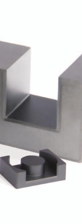
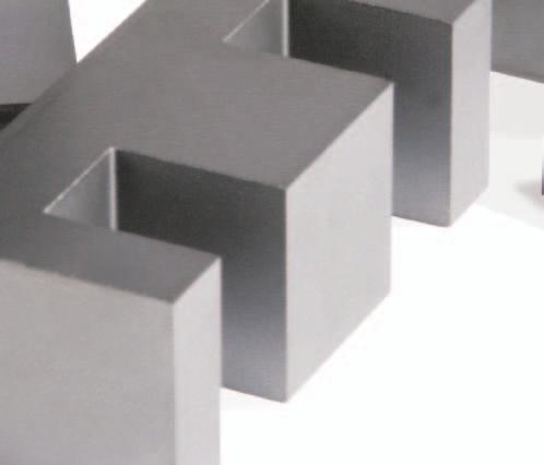
44 Block Cores Ferrites can be pressed in block form and then machined into intricate shapes. Where large sizes are required, it is possible to assemble them from two or more smaller machined or pressed sections; the variety of sizes and shapes becomes limitless. Features of Magnetics Ferrite blocks include, low porosity, extreme hardness, uniform physical properties, high density and ease of machining. J material offers high permeability; R material is suitable for power applications. AVAILABLE MATERIALS TYPE/SIZE ORDERING CODE L R P F J I 11/4/6 0_41106IC I 25/3/6 0_42515IC I 25/6/6 0_42516IC I 38 F_43808IC I 43/6/15 0_44020IC I 43/4/28 0_44308IC I 58 F_45810IC I 64 F_46410IC I 93/28/16 0_49316IC I 102/25/25 0_49925IC I 104/66/18 0_49966FB I 100/85/25 0_49985FB HOW TO ORDER Shape code Ferrite core material Used for all ferrite types Approximate length in mm Approximate height in mm Geometry code O R FB Block cores and I cores are sold per piece. 42 Block Cores - MAGNETICS

 TYPE/SIZE ORDERING CODE A B C I 11/4/6 0_41106IC 10.8 ± 0.2 1.83 ± 0.12 6.3 ± 0.13 I 25/3/6 0_42515IC 25.4 ± 0.38 3.18 ± 0.12 6.35 ± 0.25 I 25/6/6 0_42516IC 25.4 + 0.")
45 TYPE/SIZE ORDERING CODE V e (mm 3 ) MAGNETIC DATA Weight (grams each) I 11/4/6 0_41106IC I 25/3/6 0_42515IC I 25/6/6 0_42516IC I 38 F_43808IC 3, I 43/6/15 0_44020IC 3, I 43/4/28 0_44308IC 4, I 58 F_45810IC 8, I 64 F_46410IC 14, I 93/28/16 0_49316IC 35, I 102/25/25 0_49925IC 59, I 104/66/18 0_49966FB 114, I 100/85/25 0_49985FB 194, HARDWARE Bobbins Clips Refer to page 58 for hardware information. DIMENSIONS (mm) TYPE/SIZE ORDERING CODE A B C I 11/4/6 0_41106IC 10.8 ± ± ± 0.13 I 25/3/6 0_42515IC 25.4 ± ± ± 0.25 I 25/6/6 0_42516IC / ± ± 0.13 I 38 F_43808IC 38.1 ± ± ± 0.51 I 43/6/15 0_44020IC / ± /-0.6 I 43/4/28 0_44308IC 43.2 ± ± ± 0.6 I 58 F_45810IC ± ± ± 0.8 I 64 F_46410IC 64.0 ± ± ± 1.02 I 93/28/16 0_49316IC 93.0 ± ± ± 0.6 I 102/25/25 0_49925IC ± ± ± 0.6 I 104/66/18 0_49966FB ± ± ± 0.4 I 100/85/25 0_49985FB ± ± ±
46 EP Cores EP cores are round center-post cubical shapes which enclose the coil completely except for the printed circuit board terminals. This particular shape minimizes the effect of air gaps formed at mating surfaces in the magnetic path and provides a larger volume ratio to total space used. EP cores provide excellent shielding. Printed circuit bobbins, surface mount bobbins and mounting clamp assemblies are available. Typical applications for EP cores include differential mode and telecom inductors and power transformers. NOMINAL A L (MH/1000T) TYPE/SIZE ORDERING CODE L R P F T J W EP 7 P_40707UG 590 1,080 1,173 1,240 2,573 5,143 EP 10 P_41010UG 530 1,040 1,133 1,200 2,467 4,800 EP 13 P_41313UG 760 1,533 1,667 2,000 2,000 3,733 7,143 EP 17 P_41717UG 1,120 2,387 2,600 3,100 3,100 5,867 11,429 EP 20 P_42120UG 1,930 4,227 4,600 5,000 5,000 9,600 19,286 HOW TO ORDER Shape code Ferrite core material Used for all ferrite types Approximate length in mm Approximate height (per set) in mm Geometry code P J UG EP cores are sold in sets. Any practical gap available. See page EP Cores - MAGNETICS


47 TYPE/SIZE ORDERING CODE I e (mm) A e (mm 2 ) MAGNETIC DATA A min (mm 2 ) V e (mm 3 ) WaAc (cm 4 ) Weight (grams per set) HARDWARE Bobbins EP 7 P_40707UG EP 10 P_41010UG EP 13 P_41313UG EP 17 P_41717UG EP 20 P_42120UG , Refer to page 58 for hardware information. Clips DIMENSIONS (mm) TYPE/SIZE ORDERING CODE A B 2B C D 2D E F K EP 7 P_40707UG 9.2 ± ± ± ± min 5.0 min 7.2 min 3.4 max 1.7 ± 0.1 EP 10 P_41010UG 11.5 ± ± ± ± min 7.2 min 9.2 min 3.45 max 1.85 ± 0.1 EP 13 P_41313UG / ± ± / / / / / ± 0.1 EP 17 P_41717UG 18.0 ± ± ± ± ± ± ± ± ± 0.2 EP 20 P_42120UG 24.0 ± ± ± ± ± ± ± ± ±
48 Pot Cores The pot core shape is a convenient means of adjusting the ferrite structure to meet the specific requirements of an application. Both high circuit Q and good temperature stability of inductance can be obtained with these cores. Pot cores, when assembled, nearly surround the wound bobbin. This self-shielded geometry isolates the winding from stray magnetic fields or effects from other surrounding circuit elements. Typical applications for pot cores include; differential mode inductors, power transformers, power inductors, converter and inverter transformers, filters, both broadband and narrow, transformers and telecom inductors. NOMINAL A L (MH/1000T) TYPE/SIZE ORDERING CODE R P F T J W C E V PC 7/4 0_40704UG ,200 2,257 4, PC 9/5 0_40905UG 1,013 1,100 1,365 2,727 6, PC 11/7 0_41107UG 1,533 1,667 2,000 3,900 7, ,650 1,800 PC 11/9 0_41109UG 1,467 1,573 1,900 PC 14/8 0_41408UG 2,053 2,240 2,800 2,800 5,073 8,400 1,100 2,100 2,240 PC 18/11 0_41811UG 3,067 3,333 4,000 7,500 12,000 1,400 3,000 3,650 PC 18/14 0_41814UG 3,076 3,268 3,350 5,088 PC 22/13 0_42213UG 4,040 4,400 4,900 5,200 9,100 16,000 1,700 3,900 4,650 PC 26/16 0_42616UG 5,213 5,667 6,350 11,700 20,000 6,000 PC 28/23 0_42823UG 7,000 PC 30/19 0_43019UG 6,680 7,267 8,100 15,100 25,000 2,800 8,000 7,000 PC 36/22 0_43622UG 8,700 9,467 10,200 10,800 17,500 32,667 9,000 PC 42/29 0_44229UG 9,200 10,000 12,000 40,000 9,000 HOW TO ORDER O P UG Shape code Ferrite core material Used for all ferrite types Approximate diameter in mm Approximate height (per set) in mm Geometry code Pot cores are sold in sets. Any practical gap available. See page Pot Cores - MAGNETICS


49 TYPE/SIZE ORDERING CODE I e (mm) A e (mm 2 ) MAGNETIC DATA A min (mm 2 ) V e (mm 3 ) WaAc (cm 4 ) Weight (grams per set) HARDWARE Bobbins PC 7/4 0_40704UG PC 9/5 0_40905UG PC 11/7 0_41107UG PC 11/9 0_41109UG PC 14/8 0_41408UG PC 18/11 0_41811UG , PC 18/14 0_41814UG , PC 22/13 0_42213UG , PC 26/16 0_42616UG , PC 28/23 0_42823UG , PC 30/19 0_43019UG , PC 36/22 0_43622UG , PC 42/29 0_44229UG , Clips Refer to page 58 for hardware information. DIMENSIONS (mm) TYPE/SIZE ORDERING CODE A B 2B C D 2D E F G H PC 7/4 0_40704UG 7.24 ± ± ± nom 1.4 min 2.79 min 5.74 min 3.0 max 1.52 min 1.09 ± 0.05 PC 9/5 0_40905UG / / / ± / / / / ± /-0 PC 11/7 0_41107UG 11.1 ± ± ± ± / / / / ± ± 0.1 PC 11/9 0_41109UG / ± ± ± ± ± / / / /-0 PC 14/8 0_41408UG / ± ± ± / / / / / ± 0.1 PC 18/11 0_41811UG 18.0 ± ± ± ± ± ± ± ± ± ± 0.1 PC 18/14 0_41814UG 18.0 ± ± ± ± / / / / / ± 0.08 PC 22/13 0_42213UG / ± ± ± / / / / ± /-0 PC 26/16 0_42616UG 25.5 ± ± ± ± min 11.0 min 21.6 ± ± ± ± 0.1 PC 28/23 0_42823UG 27.7 ± ± ± nom 8.15 min 16.3 min 22.0 min max 3.81 min 5.56 ± 0.1 PC 30/19 0_43019UG 30.0 ± ± ± ± min 13.0 min 25.4 ± ± ± ± 0.1 PC 36/22 0_43622UG 35.6 ± ± ± ± min 14.6 min 30.4 ± ± ± ± 0.15 PC 42/29 0_44229UG 42.4 ± ± ± ± min 20.3 min 36.3 ± ± ± ±
50 PQ Cores PQ cores are designed specifically for switched mode power supplies. This design provides an optimized ratio of volume to winding area and surface area. As a result, both maximum inductance and winding area are possible with a minimum core size. The cores provide maximum power output with minimum assembled transformer weight and volume, in addition to taking up a minimum amount of area on the printed circuit board. Assembly with printed circuit bobbins and one piece clamps is simplified. This efficient design provides a more uniform cross-sectional area; thus cores tend to operate with fewer hot spots than with other designs. Typical applications include power transformers and power inductors. NOMINAL A L (MH/1000T) TYPE/SIZE ORDERING CODE L R P F T PQ 20/16 0_42016UG 1,650 3,587 3,907 4,690 PQ 20/20 0_42020UG 1,300 2,947 3,213 3,860 3,580 PQ 26/10 0_42610UG 3,900 7,733 8,413 8,080 PQ 26/14 0_42614UG 2,700 5,613 6,113 7,335 PQ 26/20 0_42620UG 2,640 5,560 6,053 7,270 7,020 PQ 26/25 0_42625UG 2,200 4,600 5,000 6,010 6,010 PQ 32/12 0_43214UG 6,867 7,467 8,960 PQ 32/20 0_43220UG 6,640 7,213 8,875 7,560 PQ 32/30 0_43230UG 4,667 5,080 6,100 6,570 PQ 35/35 0_43535UG 4,813 5,240 7,347 6,000 PQ 40/40 0_44040UG 4,267 4,640 5,580 6,100 PQ 50/50 0_45050UG 7,400 8,195 9,639 9,500 HOW TO ORDER O R UG Shape code Ferrite core material Used for all ferrite types Approximate length in mm Approximate height (per set) in mm Geometry code PQ cores are sold in sets. For clip slot dimensions see individual data sheets. Any practical gap is available. See page PQ Cores - MAGNETICS
 WaAc (cm 4 ) Weight (grams per set) Bobbins PQ 20/16 0_42016UG 37.6 61.9 59.1 2,330 0.17 13 PQ 20/20 0_42020UG 45.7 62.6 59.1 2,850 0.23 16 PQ 26/10 0_42610UG 29.4 105 93.8 3,090 0.")

51 TYPE/SIZE ORDERING CODE I e (mm) A e (mm 2 ) MAGNETIC DATA A min (mm 2 ) HARDWARE PQ 50/50 0_45050UG , Refer to page 58 for hardware information. V e (mm 3 ) WaAc (cm 4 ) Weight (grams per set) Bobbins PQ 20/16 0_42016UG , PQ 20/20 0_42020UG , PQ 26/10 0_42610UG , PQ 26/14 0_42614UG , PQ 26/20 0_42620UG , PQ 26/25 0_42625UG , PQ 32/12 0_43214UG , PQ 32/20 0_43220UG , PQ 32/30 0_43230UG , PQ 35/35 0_43535UG , PQ 40/40 0_44040UG , Clips DIMENSIONS (mm) TYPE/SIZE ORDERING CODE A B 2B C D 2D E F G PQ 20/16 0_42016UG 21.3 ± ± ± ± ± ± ± ± min PQ 20/20 0_42020UG 21.3 ± ± ± ± ± ± ± ± min PQ 26/10 0_42610UG 27.2 ± ± ± ± min 2.39 min min 12.2 max 15.5 min PQ 26/14 0_42614UG 27.2 ± ± ± ± min 6.7 min min 12.2 max 15.5 min PQ 26/20 0_42620UG 27.3 ± ± ± ± ± ± ± ± min PQ 26/25 0_42625UG 27.3 ± ± ± ± ± ± ± ± min PQ 32/12 0_43214UG 33.0 ± ± ± ± min 6.7 min 27.0 min max 19.0 min PQ 32/20 0_43220UG 33.0 ± ± ± ± ± ± ± ± min PQ 32/30 0_43230UG 33.0 ± ± ± ± ± ± ± ± min PQ 35/35 0_43535UG 36.1 ± ± ± ± ± ± ± ± min PQ 40/40 0_44040UG 41.5 ± ± ± ± ± ± ± ± ± 1.0 PQ 50/50 0_45050UG 51.0 ± ± ± ± ± ± ± ± min 49
52 RM Cores RM cores are square-designed cores that offer all the magnetic and mechanical advantages of pot cores, plus the added feature of maximizing magnetic performance while minimizing PC board space. Easy to assemble and adaptable to automation, completed units provide at least 40% savings in mounting area compared to a similar size pot core assembly. Typical applications include differential mode inductors, power inductors, filter inductors, telecom inductors and broadband transformers. NOMINAL A L (MH/1000T) TYPE/SIZE ORDERING CODE L R P F T J W C V RM 4 N N_41110UG 560 1,125 1,191 1,333 1,752 3,518 RM 4 R_41110UG 920 1,000 1,200 1,973 3,000 RM 5 N N_41510UG 900 1,720 1,867 2,100 4,133 6,000 RM 5 R_41510UG 1,720 1,867 2,100 4,133 6, ,960 RM 6R N N_41812UG 1,230 2,387 2,600 3,080 6,707 8,600 RM 6R R_41812UG 2,187 2,333 2,800 5,973 7,714 2,700 RM 6S N N_41912UG 1,250 2,213 2,400 2,880 6,000 8,600 RM 6S R_41912UG 1,987 2,160 2,600 5,387 7,714 RM 7 N N_42013UG 1,450 3,058 3,244 3,675 5,001 9,571 RM 8 N N_42316UG 1,700 2,700 2,933 5,210 8,000 12,200 RM 8 R_42316UG 2,347 2,560 3,500 6,960 10,600 RM 10 N N_42819UG 2,200 4,047 4,400 5,500 5,500 9,987 16,000 RM 10 R_42819UG RM 12 N N_43723UG 4,600 5,000 6,000 6,790 11,800 22,600 RM 14 N N_44230UG 7,000 7,540 8,782 8,130 13,096 20,735 HOW TO ORDER Shape code Ferrite core material Used for all ferrite types Approximate diameter in mm Approximate height (per set) in mm Geometry code SHAPE CODE N RM core with solid centerpost R RM core with center hole R P UG RM cores are sold in sets. Any practical gap available. See page RM Cores - MAGNETICS 2D 2B


53 TYPE/SIZE ORDERING CODE I e (mm) A e (mm 2 ) MAGNETIC DATA A min (mm 2 ) V e (mm 3 ) WaAc (cm 4 ) Weight (grams per set) HARDWARE Bobbins RM 4 N N_41110UG RM 4 R_41110UG RM 5 N N_41510UG RM 5 R_41510UG RM 6R N N_41812UG , RM 6R R_41812UG RM 6S N N_41912UG , RM 6S R_41912UG RM 7 N N_42013UG , RM 8 N N_42316UG , RM 8 R_42316UG , RM 10 N N_42819UG , RM 10 R_42819UG , RM 12 N N_43723UG , RM 14 N N_44230UG , Clips Refer to page 58 for hardware information. DIMENSIONS (mm) TYPE/SIZE ORDERING CODE A B 2B C D 2D E F G H J RM 4 N N_41110UG / ± ± / / / / / min /-0.4 RM 4 R_41110UG 11.8 max 5.2 ± ± nom 3.61 ± ± ± ± ref 2.05 ± ± 0.2 RM 5 N N_41510UG / ± ± / ± ± / / min /-0.5 RM 5 R_41510UG 14.9 max 5.2 ± ± nom 3.25 ± ± ± ± nom 2.05 ± ± 0.25 RM 6R N N_41812UG / ± ± / / / / / nom /-0.6 RM 6R R_41812UG 18.3 max 6.2 ± ± nom 4.1 ± ± ± ± nom 3.05 ± ± 0.3 RM 6S N N_41912UG 18.3 max 6.2 ± ± nom 4.1 ± ± ± ± nom 14.4 ± 0.3 RM 6S R_41912UG 18.3 max 6.2 ± ± nom 4.1 ± ± ± ± nom 3.05 ± ± 0.3 RM 7 N N_42013UG / ± ± / / / / / min /-0.7 RM 8 N N_42316UG / ± ± / ± ± / / min /-0.8 RM 8 R_42316UG 23.2 max 8.2 ± ± nom 5.53 ± ± ± ± nom 4.5 ± ± 0.4 RM 10 N N_42819UG / ± ± / / / / / min /-1.1 RM 10 R_42819UG / ± ± / / / / / min / /-1.1 RM 12 N N_43723UG / ± ± / / / / / min /-1.1 RM 14 N N_44230UG / ± ± / / / / / nom /
54 RS-DS Cores Slab cores are modified pot cores with the sides removed. The slabs can be paired with one round half of a standard pot core (RS combination) or two slabs can be paired together for a double slab (DS combination). The RS geometry offers all the advantages of pot cores for filter applications, plus many additional features for power applications. DS cores accommodate large size wire and assist in removing heat from the assembly. Typical applications for RS-DS combinations include: low and medium power transformers, switched-mode power supplies, and converter and inverter transformers. NOMINAL A L (MH/1000T) TYPE/SIZE ORDERING CODE R P F J W DS 14/08 D_41408UG 1,653 1,800 2,474 3,260 7,929 HS 14/08 H_41408UG 1,533 1,667 1,990 4,107 7,043 RS 14/08 S_41408UG 1,760 1,913 2,274 4,500 7,643 DS 18/11 D_41811UG 3,038 3,236 3,697 5,174 7,386 HS 18/11 H_41811UG 2,666 2,827 3,197 5,140 5,899 RS 18/11 S_41811UG 2,942 3,112 3,498 5,760 6,194 DS 23/11 D_42311UG 3,440 3,747 4,460 8,400 16,064 HS 23/11 H_42311UG 3,200 3,460 4,170 7,853 14,021 RS 23/11 S_42311UG 3,687 4,013 5,200 7,875 16,071 DS 23/18 D_42318UG 2,907 3,160 3,800 6,347 10,000 HS 23/18 H_42318UG 2,600 2,820 3,350 5,333 10,000 RS 23/18 S_42318UG 3,066 3,333 4,000 6,400 12,000 DS 26/16 D_42616UG 3,827 4,160 5,000 8,093 13,000 HS 26/16 H_42616UG 3,630 3,840 4,600 8,107 13,000 RS 26/16 S_42616UG 4,360 4,733 5,300 8,933 15,714 DS 30/19 D_43019UG 4,440 4,827 5,800 9,493 15,000 HS 30/19 H_43019UG 4,227 4,600 5,525 9,507 15,000 RS 30/19 S_43019UG 5,533 6,027 6,700 11,147 18,571 DS 36/22 D_43622UG 5,400 5,827 6,360 9,000 19,000 HS 36/22 H_43622UG 5,200 5,400 6,050 8,550 18,100 RS 36/22 S_43622UG 7,120 7,580 8,660 13,400 26,500 DS 42/29 D_44229UG 6,500 7,000 7,900 12,200 RS 42/29 S_44229UG 8,300 8,900 10,400 17,500 HOW TO ORDER Shape code Ferrite core material Used for all ferrite types Approximate length in mm Approximate height (per set) in mm Geometry code S P UG SHAPE CODE D - DS Core with solid centerpost H - DS Core with center hole S - RS core RS-DS cores are sold in sets. Any practical gap available, see page 15. For DS 42/29 size, see datasheets for drawings. 52 RS-DS Cores - MAGNETICS


55 TYPE/SIZE ORDERING CODE I e (mm) A e (mm 2 ) MAGNETIC DATA A min (mm 2 ) V e (mm 3 ) WaAc (cm 4 ) Weight (grams per set) HARDWARE Bobbins DS 14/08 D_41408UG HS 14/08 H_41408UG RS 14/08 S_41408UG DS 18/11 D_41811UG , HS 18/11 H_41811UG , RS 18/11 S_41811UG , DS 23/11 D_42311UG , HS 23/11 H_42311UG , RS 23/11 S_42311UG , DS 23/18 D_42318UG , HS 23/18 H_42318UG , RS 23/18 S_42318UG , DS 26/16 D_42616UG , HS 26/16 H_42616UG , RS 26/16 S_42616UG , DS 30/19 D_43019UG , HS 30/19 H_43019UG , RS 30/19 S_43019UG , DS 36/22 D_43622UG , Clips Refer to page 44 for hardware information. HS 36/22 H_43622UG , RS 36/22 S_43622UG , DS 42/29 D_44229UG , RS 42/29 S_44229UG , DIMENSIONS (mm) Refer to page 58 for hardware information. TYPE/SIZE ORDERING CODE A B 2B C D 2D E F G H DS 14/08 D_41408UG ± ± ± ± ± ± ± ± min HS 14/08 H_41408UG 14 ± / / ± min 5.58 min 11.6 min 5.99 max 7.6 min 3.1 ± 0.1 RS 14/08 S_41408UG 14 ± / / ± min 5.58 min 11.6 min 5.99 max 7.6 min 3.1 ± 0.1 DS 18/11 D_41811UG 18 ± ± ± ± ± ± min HS 18/11 H_41811UG 18 ± ± ± ± ± ± ± ± min 3.1 ± 0.1 RS 18/11 S_41811UG 18 ± ± ± ± ± ± ± ± min 3.1 ± 0.1 DS 23/11 D_42311UG ± ± ± ± min 7.26 min min 9.9 max min HS 23/11 H_42311UG ± ± ± ± min 7.26 min min 9.9 max min 5.1 ± 0.1 RS 23/11 S_42311UG 22.9 ± ± ± ± ± ± ± ± min 5.1 ± 0.1 DS 23/18 D_42318UG ± ± ± ± min min min 9.9 max min HS 23/18 H_42318UG ± ± ± ± min min min 9.9 max 13.2 min 5.08 ± 0.1 RS 23/18 S_42318UG 22.9 ± ± ± ± ± ± ± ± min 5.1 ± 0.1 DS 26/16 D_42616UG 25.5 ± ± ± nom 5.51 min min min max 15.5 min HS 26/16 H_42616UG 25.5 ± ± ± nom 5.51 min min min max 15.5 min 5.56 ± 0.1 RS 26/16 S_42616UG 25.5 ± ± ± nom 5.51 min min min max 15.5 min 5.56 ± 0.1 DS 30/19 D_43019UG 30 ± ± ± ± min 13 min 25 min max min HS 30/19 H_43019UG 30 ± ± ± ± min 13 min 25 min max min 5.56 ± 0.1 RS 30/19 S_43019UG 30 ± ± ± ± min 13 min 25 min max min DS 36/22 D_43622UG ± ± ± nom 7.29 min min 29.9 min 16.1 max 20.3 min HS 36/22 H_43622UG ± ± ± nom 7.29 min min min 16.1 max 20.3 min 5.56 ± 0.1 RS 36/22 S_43622UG ± ± ± nom 7.4 ± ± min 16.1 max 20.3 min DS 42/29 D_44229UG 42.4 ± ± ± nom min min min 17.7 max 25.0 min RS 42/29 S_44229UG 42.4 ± ± ± nom min min min 17.7 max 25.0 min 5.56 ±
56 U, I Cores U shape cores are ideal for higher power operation in tight spaces or unusual form factors. The long legs of U core support low leakage inductance designs and facilitate superior voltage isolation. U/I combinations provide for economical assembly. U cores are ideal for power transformer applications. NOMINAL A L (MH/1000T) TYPE/SIZE ORDERING CODE L R P F J W U 11/4/6 0_41106UC ,010 1,662 I 11/2/6 0_41106IC 960 1,020 1,150 1,687 U 22/21/6 0_42220UC ,360 2,107 3,429 U 25/13/13 0_42512UC 1,907 2,067 2,480 4,400 U 25/16/6 0_42515UC 1,107 1,333 1,600 2,507 I 25/6/6 0_42516IC 660 1,480 1,650 1,770 2,907 U 25/16/12 0_42530UC 2,093 2,280 2,740 4,860 U 93/76/16 0_49316UC 3,450 3,730 4,110 8,100 I 93/28/16 0_49316IC 4,600 4,960 5,840 10,500 U 93/76/30 0_49330UC 7,219 U 93/76/32 0_49332UC 7,700 U 126/91/20 0_49920UC 3,000 3,572 4,265 6,967 U 102/57/25 0_49925UC 4,533 5,500 6,500 I 102/25/25 0_49925IC 5,707 6,200 7,440 HOW TO ORDER Shape code Ferrite core material Used for all ferrite types Approximate length in mm Approximate width in mm Geometry code GEOMETRY CODE UC U core IC I core O F UC U and I cores are sold per piece (for sets multiply by 2). 54 U, I Cores - MAGNETICS


57 TYPE/SIZE ORDERING CODE I e (mm) A e (mm 2 ) MAGNETIC DATA A min (mm 2 ) V e (mm 3 ) WaAc (cm 4 ) Weight (grams per set) U 11/4/6 0_41106UC I 11/2/6 0_41106IC U 22/21/6 0_42220UC , U 25/13/13 0_42512UC , U 25/16/6 0_42515UC , I 25/6/6 0_42516IC , U 25/16/12 0_42530UC , U 93/76/16 0_49316UC , I 93/28/16 0_49316IC , U 93/76/30 0_49330UC , ,490 U 93/76/32 0_49332UC , ,600 U 126/91/20 0_49920UC , ,360 U 102/57/25 0_49925UC , I 102/25/25 0_49925IC , HARDWARE Bobbins Clips Refer to page 58 for hardware information. DIMENSIONS (mm) TYPE/SIZE ORDERING CODE A B C D E L U 11/4/6 0_41106UC ± ± ± ± ± ± 0.13 I 11/2/6 0_41106IC 10.8 ± ± ± 0.13 U 22/21/6 0_42220UC 22.1 ± ± ± min 9.5 ± ± 0.18 U 25/13/13 0_42512UC 25.4 ± ± ± min 12.8 ref 6.3 ± 0.13 U 25/16/6 0_42515UC 25.4 ± ref 6.35 ± min 12.7 ref 6.45 ± 0.15 I 25/6/6 0_42516IC / ± ± 0.13 U 25/16/12 0_42530UC 25.4 ± ref 12.7 ± min 12.7 ref 6.45 ± 0.15 U 93/76/16 0_49316UC 93.0 ± ± ± ± ± ref I 93/28/16 0_49316IC 93.0 ± ± ± 0.6 U 93/76/30 0_49330UC 93.0 ± ± ± ± ± ref U 93/76/32 0_49332UC 93.0 ± ± ± ± ± ref U 126/91/20 0_49920UC ± ± ± ± ± ref U 102/57/25 0_49925UC ± ± ± ± ± ± 0.8 I 102/25/25 0_49925IC ± ± ±
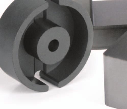
58 UR Cores UR cores are an excellent choice for high current designs and conditions where vibration occurs. The open window area accommodates large conductors. Holes through the center, or grooves on the outer legs of the core provide a method to secure the core to the PCB with mounting hardware. Typical applications include: the output transformer application in welding, audio amplifiers, traction and other high-power designs. NOMINAL A L (MH/1000T) TYPE/SIZE ORDERING CODE R P F UR 41/21/11 0_44119UC 1,627 1,773 2,130 UR 41/21 0_44121UC 1,880 2,047 2,465 UR 41/25 0_44125UC 1,600 1,747 2,105 UR 41/30 0_44130UC 1,400 1,520 1,830 UR 57 0_45716UC 2,600 3,061 3,622 UR 59 0_45917UC 3,027 3,274 3,881 UR 64 0_46420UC 3,787 4,098 4,864 HOW TO ORDER Shape code Ferrite core material Used for all ferrite types Approximate length in mm Approximate depth in mm Geometry code O P UC UR cores are sold per piece (for sets multiply by 2). For UR 64 size, refer to datasheets for drawings. 56 UR Cores - MAGNETICS

 TYPE/SIZE ORDERING CODE A B C D E S T UR 41/21/11 0_44119UC 41.78 ± 0.81 20.9 ± 0.12 11.94 ± 0.25 13.4 min 18.8 ± 0.56 3.18 nom 34.66 ref UR 41/21 0_44121UC 41.78 ± 0.81 20.62 ± 0.")
59 TYPE/SIZE ORDERING CODE I e (mm) A e (mm 2 ) MAGNETIC DATA A min (mm 2 ) V e (mm 3 ) WaAc (cm 4 ) Weight (grams per set) HARDWARE Bobbins UR 41/21/11 0_44119UC , UR 41/21 0_44121UC , UR 41/25 0_44125UC , UR 41/30 0_44130UC , UR 57 0_45716UC , UR 59 0_45917UC , UR 64 0_46420UC , Clips Refer to page 58 for hardware information. DIMENSIONS (mm) TYPE/SIZE ORDERING CODE A B C D E S T UR 41/21/11 0_44119UC ± ± ± min 18.8 ± nom ref UR 41/21 0_44121UC ± ± ± ± ± ± nom UR 41/25 0_44125UC ± ± ± ± ± ± nom UR 41/30 0_44130UC ± ± ± min 18.8 ± ± ref UR 57 0_45716UC ± / ± / ± ± ± 0.8 UR 59 0_45917UC ± ± ± ± ± ± ± 0.1 UR 64 0_46420UC 64.0 ± ± ± ± ± min 44.0 ±

60 Hardware SIZE TYPE P/N 0200 TC SMC06018A SMH05025A SMH07058A 0301 TC SMC06018A SMH05025A SMH07058A 0401 TC SMC06018A SMH05025A SMH07058A 0402 TC SMC06018A SMH05025A SMH07058A 0502 TC SMC06018A SMH05025A SMH07058A 0503 TC SMC06018A SMH05025A SMH07058A 0601 TC SMC06018A SMH07058A 0603 TC SMC06018A SMH07058A 0704 PC 00B TC SMH07058A 0707 EP 0AC BC PCB07076B SMB07076A 0905 PC 00B C ER 00C09061A SMB09068A 1009 EFD 00C1009B1 PCB1009B EP 00C10102A PCB10108A SMB10108A 1107 PC 00B B1107A2 00C SMH11078A 1110 RM 00C PCB11104B 1212 EFD 00C1212B1 PCB1212B EP 0AC BC PCB1313TB SMB1313B TC TVB22066A TVH22064A 1407 TC TVB22066A TVH22064A SIZE TYPE P/N 1408 PC 00B RS/DS 00B C W PCB PCB PCB PCB PCB PCB1408S1 SMH1408TA TBA TCA1408B1 TCA1408C P-EC 00C TC TVB22066A TVH22064A 1506 TC TVB22066A TVH22064A 1510 RM 00C PCB15104A PCB15104B PCB PCB TBP TCF1510R EFD SMB1515TA 00C1515B1 PCB1515B TC TVB22066A TVH22064A 1717 EP 00C17172A PCB17178A 1805 P-EC 00C EC 00B PCB1808B TC TVB22066A TVH22064A 1811 PC 00B RS/DS 00B B C W PCB PCB PCB PCB SMH1811LA TCA1811B RM 00C PCB PCB TBA TCA1812C2 SIZE TYPE P/N 1912 RM 00C PCB PCB TBA TCA1812C PQ 00C PCB2016FB 2019 EFD 00C2019B1 PCB2019B PQ 00C PCB2020FB 2106 TC TVB22066A TVB2908TA TVH22064A TVH25074A 2109 TC TVB22066A TVB2908TA TVH22064A TVH25074A 2120 EP 0AC BC PCB2120TB 2206 TC TVB22066A TVB2908TA TVH22064A TVH25074A 2207 TC TVB22066A TVB2908TA TVH22064A TVH25074A 2212 TC TVB22066A TVB2908TA TVH22064A TVH25074A 2213 PC 00B B B C W PC PCB PCB PCB PCB TBP TBP2213A0 TCF2213B P-EC 00C RS/DS PCB2311T RM 00C PCB PCB PCB RS/DS PCB2318T1 SIZE TYPE P/N 2507 TC TVB2908TA TVH22064A TVH25074A 2508 TC TVB2908TA TVH22064A TVH25074A 2510 EC 00B PCB2510V1 PCB2510V EC-EC 00B EC PCB2520TA 2523 EFD 00C2523B1 PCB2523B PC 00B RS/DS 00B B C PC PCB PCB PCB PCB PCB PCB2616TA TBP TCF2800B PQ 00C PCB2620LA 2625 PQ 00C PCB2625LA 2819 RM 00C PCB2819L PC 00B TC TVB2908TA TVB3610FA TVH25074A 2915 TC TVB2908TA TVB3610FA TVH25074A 2929 ETD 00C2929B1 PCB2929B EC PCB3007T EC PCB3009LA 3019 PC 00B RS/DS 00B B C PCB PCB PCB3019T1 TBP TCF2800B EFD 00C3030B1 PCB3030B1 SIZE TYPE P/N 3113 TC TVB2908TA TVB3610FA 3205 TC TVB3610FA TVH38134A 3220 PQ 00C PCB3220B PQ 00C PCB3230B ETD 00C PCB3434FB 3515 EC 00B PCB3515M1 PCB3515M EC 00B AC CC PCB PCH EER PCB3521LA 3535 PQ 00C PCB3535LA 3610 TC TVH38134A 3615 TC TVB3610FA TVH38134A 3622 PC 00B RS/DS 00B C C PCB PCB3622L1 TBP TCF2800B1 TCF4000B RM PCB3723L TC TVB3610FA TVH38134A 3813 TC TVB3610FA TVH38134A TVH49164A 3825 TC TVB3610FA TVH38134A TVH49164A 3939 ETD 00C PCB3939SB 4015 TC TVH49164A 4020 EC-IC 00B PCB4020N EC PCB4022N PQ 00C PCB4040FA 4119 EC 00B AC BC CC PCB SIZE TYPE P/N 4119 EC PCH EER PCB4216FA 4229 PC 00B RS/DS 00B C PCB4229L1 TBP TCF2800B1 TCF4000B EC PCB4317M TC TVH49164A 4444 ETD 00C PCB TC TVH49164A 4721 EC PCB4721M TC TVH49164A 4920 TC TVH49164A 4925 TC TVH49164A 4932 TC TVH49164A 4949 ETD 00C PCB PCB4949WA 5050 PQ 00B5050B EC 0AC BC CC PCB PCH B5224B ETD 00C5454B1 PCB5454B EC 00B5528B1 PCB5528WC 5530 EC PCB5530FA 5724 EC 00B PCB5724M EC-IC 00C C ETD 00C PCB5959AA 6113 TC TVH49164A TVH61134A 6326 TC TVH49164A TVH61134A 6410 EC-IC 00C C EC 00B EC 00B AC BC PCB PCH EC 00B EC 00B Hardware - MAGNETICS
61 Power Design Ferrite is an ideal core material for transformers, inverters and inductors in the frequency range 20 khz to 3 MHz, due to the combination of low core cost and low core losses. Ferrites may be used in the saturating mode for low power, low frequency operation (<50 watts and 10 khz). Ferrite cores may also be used in fly-back transformer designs, which offer low core cost, low circuit cost and high voltage capability. Powder cores (MPP, High Flux, Kool Mµ and XFLUX ) offer soft saturation, higher B max and better temperature stability and may be the best choice in some flyback or inductor applications. CORE GEOMETRIES POT CORES Pot Cores, when assembled, nearly surround the wound bobbin. This aids in shielding the coil from pickup of EMI from outside sources. The pot core dimensions follow IEC standards so that there is interchangeability between manufacturers. Both plain and printed circuit bobbins are available, as are mounting and assembly hardware. ROUND SLAB, DOUBLE SLAB & RM CORES Slab-sided solid center post cores resemble pot cores, but have a section cut off on either side of the skirt. The additional openings allow larger wires to be accommodated and assist in removing heat from the assembly. RM cores are also similar to pot cores, but are designed to minimize board space, providing at least a 40% savings in mounting area. Printed circuit or plain bobbins are available. One piece clamps permit simple assembly. Low profile is possible. The solid center post generates less core loss and minimizes heat buildup. PQ CORES PQ cores are designed specifically for switched mode power supplies. The design optimizes the ratio of core volume to winding and surface area. As a result, power output, inductance and winding area are maximized with a minimal core weight, volume and PCB footprint. Assembly is simple using printed circuit bobbins and one piece clamps. This efficient design provides a more uniform cross-sectional area; cores tend to operate with fewer hot spots than with other geometries. EC, ETD AND EER CORES These shapes combine the benefits of E cores and pot cores. Like E cores, they have a wide opening on each side. This provides ample space for the large wires used for low output voltage switched mode power supplies. It also increases the flow of air which keeps the assembly cooler. The center post is round, like that of the pot core. One of the advantages of the round center post is that the winding has a shorter path length around it (11% shorter) than the wire around a square center post with an equal area. This reduces the losses of the windings by 11% and enables the core to handle a higher output power. The round center post eliminates the sharp bend in the wire that occurs with winding on a square center post. E, ER AND PLANAR E CORES E cores offer the advantage of simple bobbin winding and ease of assembly. A wide variety of standard lamination-size, metric and DIN sizes are available. E cores are a low-cost choice in designs that do not require self-shielding. Planar cores are the best selection for low profile applications. Copper traces that are layered in the printed circuit board are the windings in most planar applications. This type of design provides superior thermal characteristics, economical assembly, low leakage inductance, and excellence in consistency of performance. EP CORES EP Cores are round center-post cubical shapes which enclose the coil completely except for the printed circuit board terminals. The particular shape minimizes the effect of air gaps formed at mating surfaces in the magnetic path and provides a larger volume ratio to total space used. Shielding is excellent. TOROIDS Toroids are the least expensive ferrite shape. Available in a variety of sizes, outer diameters of 2.54 mm 140 mm, toroids have good self-shielding properties. The fact that the core is a solid with no sections to assemble makes it a good choice if mechanical integrity is important in a high vibration environment. Toroid cores are available uncoated or with an epoxy, nylon or Parylene coating. CORE MATERIALS POWER Magnetics R, P, F, T and L materials provide superior saturation, high temperature performance, low losses and product consistency. T perm is ideal for consistent performance over a wide temperature range. Applications for T include: Automotive, Electronic Lighting, Outdoor LCD Screens, Mobile Handheld Devices and AC adapters and chargers. L perm was formulated for high-frequency and high-temperature applications. L is designed for DC-DC converters, Filters and Power Supplies that operate from Megahertz. Curie temperature is high for a ferrite material at 300 C. R perm provides the best core losses for frequencies up to 500 khz. P perm offers similar properties to R material, but is more readily available in some sizes. F perm is an established material with a relatively high permeability and 210 C Curie temperature. Power Supplies, DC-DC Converters, Handheld Devices, High Power Control (gate drive) and EMI Filters are just a few of the applications that are typical for Magnetics ferrite power materials. FILTER Magnetics high permeability materials are engineered for optimum frequency and impedance performance in signal, choke and filter applications. J and W materials offer high impedance for broad band transformers, and are also suitable for low-level power transformers. J perm is a medium perm general-purpose material. J s properties are well suited both for EMI/RFI filtering and broadband transformers. W perm has set the industry standard for high perm materials. In filter applications, W perm has 20-50% more impedance below 1 MHz than J perm. LINEAR FILTERS AND SENSORS Magnetics C, E and V materials offer excellent properties for low-level signal applications. These materials set the standard for high quality factor, long-term stability and precise and adjustable inductance. Applications for these materials include high Q filters, wideband transformers, pulse transformers and RLC tuned circuits. 59
62 Inductor Design Ferrite E cores and pot cores offer the advantages of decreased cost and low core losses at high frequencies. For switching regulators, power materials are recommended because of their temperature and DC bias characteristics. By adding air gaps to these ferrite shapes, the cores can be used efficiently while avoiding saturation. These core selection procedures simplify the design of inductors for switching regulator applications. One can determine the smallest core size, assuming a winding factor of 50% and wire current carrying capacity of 500 circular mils per ampere. Only two parameters of the design applications must be known: (a) Inductance required with DC bias (b) DC current 1. Compute the product of LI² where: L = inductance required with DC bias (millihenries) I = maximum DC output current + 1/2 AC Ripple 2. Locate the LI² value on the Ferrite Core Selector charts on the following page. Follow this coordinate in the intersection with the first core size curve. Read the maximum nominal inductance, A L, on the Y-axis. This represents the smallest core size and maximum A L at which saturation will be avoided. 3. Any core size line that intersects the LI² coordinate represents a workable core for the inductor if the core s A L value is less than the maximum value obtained on the chart. 4. Required inductance L, core size, and core nominal inductance (A L ) are known. Calculate the number of turns using ;'' L N = 10 3 where L is in millihenries. 5. Example: If I MAX = 8 Amps; L, inductance required = 100 µhenries LI² = (0.100 mh) X (8² Amps) = 6.4 millijoules 6. There are many ferrite cores available that will support the energy required. Any core size that the LI² coordinate intersects can be used at the A L value shown on the chart. 7. Some choices based upon an LI² value of 6.4 millijoules are: Pot core A L = 400 Double Slab A L = 250 PQ core A L = 300 E core A L = For the following A L values the number of turns required is: A L = 400, N = 16 A L = 300, N = 19 A L = 250, N = 20 Make sure the wire size chosen will support the current and fit into the core set. 60 Inductor Design - MAGNETICS A L A L (mh/1000 turns) A L (mh/1000 turns) A L (mh/1000 turns) E B C D F POT CORES G H J K L LI 2 (millijoules) A B C D ETD AND EER CORES E F LI 2 (millijoules) H RS (ROUND-SLAB) & DS (DOUBLE-SLAB) CORES A B LI 2 (millijoules) C G I D E F B C D E F G H J K L A (EER28) B (ETD34) C (EER35L) D (ETD39) E (EER40) F (EER42) (ETD44) G (EER48) (EER54) H (ETD49) I (ETD59) A (RS) B (DS, RS) (DS, RS) C (DS) D (DS, RS) E (DS) F (DS)
63 Inductor Design A L (mh/1000 turns) A E C RM AND EP CORES B D F G H J A (EP7) (EP10) (RM4) B (EP13) C (RM5) D (EP17) E (RM6) F (RM8) G (EP20) H (RM10) J - R43723 (RM12) A L (mh/1000 turns) A PQ CORES B C D E F A B C D E F A L (mh/1000 turns) A L (mh/1000 turns) LI 2 (millijoules) A LAMINATION SIZE E CORES B C D LI 2 (millijoules) E H I J K L 2000 PLANAR EE AND EI CORES D G E H F I J K 600 C B A LI 2 (millijoules) F G A B C D E F G H I J K L A (EE, EI) (EE, EI) B (EE, EI) C (EE, EI) D (EE, EI) E (EE, EI) (EE, EI) F (EE, EI) G (EE, EI) H (EE, EI) (EE, EI) I (EE, EI) J (EE, EI) K (EE) A L (mh/1000 turns) A L (mh/1000 turns) LI 2 (millijoules) A C B H E CORES F D LI 2 (millijoules) 2000 ER, EFD, AND EC CORES K H L M G I J 400 F 200 A B D C E E G A B C D E F G H A (EFD) B (ER) (ER) (EFD) C (ER) D (EFD) E (ER) F (ER) G (ER) (EFD) H (ER) (EC) I (ER) (EFD) J (ER) K (EC) L (EC) M (EC) LI 2 (millijoules) 61
64 Header Inductor1 Header Design Continued DC BIAS DATA FOR GAPPED APPLICATIONS NI = 0.80 x H x l e Where NI = maximum allowable ampere-turns H = DC Bias level l e = core path length (cm) The above curves represent the locus of points up to which effective permeability remains constant. They show the maximum allowable DC bias, in ampere-turns, without a reduction in inductance. Beyond this level, inductance drops rapidly. Example: How many ampere-turns can be supported by an R42213A315 pot core without a reduction in inductance value? l e = 3.12 cm µ e = 125 Maximum allowable H = 25 Oersted (from the graph above) NI (maximum) = 0.80 x H x l e = 62.4 ampere-turns or (Using top scale, maximum allowable H = 20 A T/cm.) NI (maximum) = A T/cm x l e = 20 x 3.12 = 62.4 A T µ A e = L l e 4 p A e 1 1 l = + g µ e µ i l e A e = effective cross sectional area (cm 2 ) A L = inductance/1,000 turns (mh) µ i = initial permeability l g = gap length (cm) 62 Inductor Design - MAGNETICS
65 Transformer Design Magnetics offers two methods to select a ferrite core for a power application. CORE SELECTION BY POWER HANDLING CAPACITY The Power Chart characterizes the power handling capacity of each ferrite core based upon the frequency of operation, the circuit topology, the flux level selected, and the amount of power required by the circuit. If these four specifics are known, the core can be selected from the Power Chart on page 6. CORE SELECTION BY WaAc PRODUCT The power handling capacity of a transformer core can also be determined by its WaAc product, where Wa is the available core window area, and Ac is the effective core cross-sectional area. Using the equation shown below, calculate the WaAc product and then use the Area Product Distribution (WaAc) Chart to select the appropriate core. WaAc = Product of window area and core area (cm 4 ) P o = Power Out (watts) D cma = Current Density (cir. mils/amp) Current density can be selected depending upon the amount of heat rise allowed. 750 cir. mils/amp is conservative; 500 cir. mils is aggressive. B max = Flux Density (gauss) selected based upon frequency of operation. Above 20kHz, core losses increase. To operate ferrite cores at higher frequencies, it is necessary to operate the core flux levels lower than ± 2 kg. The Flux Density vs. Frequency chart shows the reduction in flux levels required to maintain 100 mw/cm³ core losses at various frequencies, with a maximum temperature rise of 25 C. for a typical power material, MAGNETICS P. A c = Core area in cm 2 ƒ = frequency (hertz) K t = Topology constant (for a space factor of 0.4). Topology constants K t WaAc = Forward converter = Push-Pull = Half-bridge = Full-bridge = Flyback = (single winding) Flyback = (multiple winding) P o D cma K t B max ƒ For individual cores, WaAc is listed in this catalog under Magnetic Data. The WaAc formula was obtained from derivations in Chapter 7 of A. I. Pressman s book, Switching Power Supply Design. Choice of B max at various frequencies, D cma and alternative transformer temperature rise calculations are also discussed in Chapter 7 of the Pressman book FLUX DENSITY VS. FREQUENCY P PERM FREQUENCY khz Once a core is chosen, the calculation of primary and secondary turns and wire size is readily accomplished. Np = I p = KWa = N p A wp + N s A ws Where A wp = primary wire area A ws = secondary wire area Assume K =.4 for toroids;.6 for pot cores and E-U-I cores Assume N p A wp = 1.1 N s A ws to allow for losses and feedback winding efficiency e = V p X 10 8 P in E in 4BA c P out ee in P out E in = Voltage Regulation (%) = N s = I s = P out P out + wire losses + core losses R s + (N s /N p ) 2 R p R load V s V p P out E out Np x
66 Typical Power Handling Chart Power in Watts 20 khz 50 khz 100kHz 250 khz Pot, RS, DS E Cores RM, PQ, EP UU, UI, UR ETD, EER, EC EFD, Planar Toroid RS DS PC EE EE EP RM RM EE EE TC TC TC TC TC TC TC TC TC TC PC RS DS HS EE EP RM PQ PQ EFD EI EI TC TC TC TC EE EE RM PC PQ TC RS DS HS PQ EFD RS DS HS EE EI EP PQ UI EE EI EI TC TC EE TC EE EFD RS PC PQ TC EE RM TC EE EE HS PQ EE PC RS DS PC EE UU UU ETD EE TC EE EE PQ EC EI TC DS HS RM UU UU EER EER ETD TC TC TC RS EE EE EI EI PC PQ EE TC EE RM EC EE EI EER ETD EE TC TC EE TC 64 Transformer Design - MAGNETICS
67 Typical Power Handling Chart Power in Watts 20 khz 50 khz 100kHz 250 khz Pot, RS, DS E Cores RM, PQ, EP UU, UI, UR ETD, EER, EC EFD, Planar Toroid EE UR RS DS PQ UR EER TC PC EE EER ETD EER EC EI 43615TC EE UR EE PQ EER TC EE EE UR EER ETD EI TC TC TC EE TC TC PQ EE EE UR ETD EE TC TC EE TC EE UR ETD EC TC TC UR TC TC EE EE EE UI UU EE UU UU UU UI UU TC TC TC EE TC TC 48625TC TC TC TC TC TC Ferrite Core selection listed by typical Power Handling Capabilities (Chart is for Power Ferrite Materials, F, P, R, L and T, Push-Pull Square wave operation) Wattage values shown above are for push-pull converter design. De-rate by a factor of 3 or4 for flyback. De-rate by a factor of 2 for feed-forward converter. Example: For a feed-forward converter to be used at 300 watts select a core that is rated at 600 watts based on the converter topology. Note: Assuming Core Loss to be Approximately 100 mw/cm³, B Levels Used in this Chart 20 khz mt, khz mt, khz - 90 mt, khz - 70 mt, 700 gauss 65
68 Area Product Distribution (WaAc) Chart WaAc (cm 4 ) RS, DS, HS E EC, EER, EP, RM ER Planar Pot PQ TC U, UR EFD, ETD < TC TC TC TC TC TC TC EE UG EE UG TC EFD EE EP EI UG EI TC EFD EP EE EE UG TC UI RM EE RS DS HS EE EFD RM EE UG TC UU EE EP EE EI TC EE EI EI TC TC HS RM EE TC TC TC TC TC EP EE UG TC RM RS DS EI EE EE UG UG TC TC DS HS 41808EE 42517EI 41450TC EFD UG RS EE EE EI TC RS DS HS EE EI EFD RM EP EE EI UG UG UG TC 41610TC RM UG RS DS HS EE EFD EE EI UG TC UI EE EE TC EE RM EI EI UG UG TC TC EE EER EE TC EE DS HS EE EE EE UG UG UU UU RS EE EFD EE UG TC EER EC EE UG TC UU EI TC 66 Transformer Design - MAGNETICS
69 Area Product Distribution (WaAc) Chart WaAc (cm 4 ) RS, DS, HS E EC, EER, EP, RM ER Planar Pot PQ TC U, UR EFD, ETD RS DS HS EE EE EI ETD RM EI TC TC UU EE EE EE EER ETD EER EC RS DS EE EER EER EE EE ETD EER EC EER RM EE EI EE EE UG UG TC TC TC UG TC TC UR UR EI UG TC UR UG TC TC EE EE ETD EI TC EE TC TC EE UG TC ETD TC UR EE EE TC EE EC TC ETD 45917U R EE TC TC TC UU EE EE TC TC EE TC TC TC UI TC EE UI EE TC TC TC TC UU TC UU TC UR UU 67
")

70 Website For updates and more in-depth product information, visit mag-inc.com or mag-inc.com.cn Design Equations Area Product Distribution (WaAc) and Power Charts Product Datasheets Product Catalogs Design Software Distributor Stock Check Part Number Search Cross Reference Tool 68 Website - MAGNETICS


71 Other Products from Magnetics POWDER CORES Powder cores are excellent as low loss inductors for switched-mode power supplies, switching regulators and noise filters. Most core types can be shipped immediately from stock. Kool Mµ powder cores have a higher energy storage capacity than MPP cores and are available in six permeabilities from 14µ through 125µ. Kool Mµ toroids are available in sizes identical to MPP cores, and extremely large (>6.5 or 165 mm) toroids/shapes are possible with interlocking Kool Mµ segments. This material is also available in a number of E-core sizes. Permeability for Kool Mµ E-cores is from 26 to 90 and sizes are tooled ranging from the EF 12.6 to the 160LE size. Kool Mµ blocks and U cores are also available. Molypermalloy powder cores (MPP) are available in ten permeabilities ranging from 14 through 550, and have guaranteed inductance limits of ±8%. Insulation on the cores is a high dielectric strength finish not affected by normal potting compounds and waxes. Thirty sizes include I.D.s from (1.78 mm) to (102.4 mm) and O.D.s from (3.56 mm) to 6.5 (165.1 mm). Standard cores include either temperature stabilized (as wide as -65 C to 125 C for stable operation) or standard stabilization. TAPE WOUND CORES Tape wound cores are made from high permeability alloys of nickel-iron, cobalt-iron, and grain oriented silicon-iron. The alloys are known as Orthonol, Alloy 48, Square Permalloy 80, Supermalloy, Supermendur and Magnesil. Cores are available in more than 50 standard sizes. For a wide range of frequency applications, materials are produced in thicknesses from 1/2 mil (0.013 mm) through 4 mils (0.102 mm). Cases are robust nylon boxes, rated for 200 C continuous operation and 2,000 voltage minimum breakdown. Applications include: magnetic amplifiers, reactors, regulators, static magnetic devices and current transformers. Miniature Tape Wound Bobbin Cores are manufactured from Permalloy 80 and Orthonol ultra-thin tape ( to thick). They are available in widths from to (wider on special request). Wound on non-magnetic stainless steel bobbins, core diameters are available down to 0.159, with flux capacities as low as several maxwells. Magnetics sophisticated pulse test equipment reproduces most test programs and can measure accurately in the millivoltmicrosecond region. Applications include: magnetometers, flux gates, oscillators, inverters and magnetic amplifiers. High Flux powder cores have a much higher energy storage capacity than MPP cores and are available in six permeabilities from 14µ through 160µ. High Flux cores are available in sizes identical to MPP cores. Magnetics XFLUX distributed air gap cores are made from 6.5% silicon iron powder. A true high temperature material, with no thermal aging, XFLUX offers lower losses than powder iron cores and superior DC Bias performance. The soft saturation of XFLUX material offers an advantage over ferrite cores. XFLUX cores are ideal for low and medium frequency chokes where inductance at peak is critical. 69
Experience the Power of Confidence
 Experience the Power of Confidence the confidence of over fifty years of expertise in the research, design, manufacture and support of high quality magnetic materials and components. A major supplier of
Experience the Power of Confidence
 Experience the Power of Confidence the confidence of over fifty years of expertise in the research, design, manufacture and support of high quality magnetic materials and components. A leading manufacturer
Section Toroids COATING CODE (SEE PG 13.2) FERRITE CORE MATERIAL TYPE USED FOR ALL FERRITE TYPES APPROXIMATE DIAMETER IN MM
 FERRITE CORE MATERIAL TYPE USED FOR ALL FERRITE TYPES APPROXIMATE DIAMETER IN MM") TOROIDS Ferrite toroids offer high magnetic efficiency as there is no air gap, and the cross sectional area is uniform. Available in many sizes (s from 2.54mm to 107mm) and materials (permeabilities ranging
TOROIDS Ferrite toroids offer high magnetic efficiency as there is no air gap, and the cross sectional area is uniform. Available in many sizes (s from 2.54mm to 107mm) and materials (permeabilities ranging
Section 13. Toroids COATINGS
 Section 13. Toroids Ferrite toroids offer high magnetic efficiency as there is no air gap, and the cross sectional area is uniform. Available in many sizes ('s from.100" to 3.375") and materials (permeabilities
Large Kool Mµ Core Shapes
 Large Kool Mµ Core Shapes Technical Bulletin Ideal for high current inductors, large Kool Mµ geometries (E cores, Toroids, U Cores and Blocks) offer all the advantages of Kool Mµ material, low core loss,
Section 13. Toroids. Parylene C is a trademark of Union-Carbide Corp. Material R P F J W H. Color Blue Green White Red Yellow Purple 13.
 Section 13. Toroids Ferrite toroids offer high magnetic efficiency as there is no air gap, and the cross sectional area is uniform. vailable in many sizes ( s from.100" to 3.375"), and materials (permeabilities
Ferroxcube Soft Ferrites (MnZn - NiZn) Company Introduction
 Company Introduction") Ferroxcube Soft Ferrites (MnZn - NiZn) Company Introduction Founder of Ferrite Cores 1941 E Core 5.3 to 100 Most common Very cheap Toroid 2.5 to 140 Best material properties Specialized winding E I Core
Ferroxcube Soft Ferrites (MnZn - NiZn) Company Introduction Founder of Ferrite Cores 1941 E Core 5.3 to 100 Most common Very cheap Toroid 2.5 to 140 Best material properties Specialized winding E I Core
Large Kool Mµ Core Shapes
 Large Kool Mµ Core Shapes TECHNICAL BULLETIN Ideal for high current inductors, large Kool Mµ geometries (E cores, U Cores and Blocks) offer all the advantages of Kool Mµ material, low core loss, excellent
Solving Electromagnetic Interference (EMI) with Ferrites
 with Ferrites") Solving Electromagnetic Interference (EMI) with Ferrites What are ferrites? How do ferrites help Suppress EMI? How to chose proper ferrite and component Material Characteristics Material and Core Selection
Solving Electromagnetic Interference (EMI) with Ferrites What are ferrites? How do ferrites help Suppress EMI? How to chose proper ferrite and component Material Characteristics Material and Core Selection
Large Kool Mµ Core Shapes
 Large Kool Mµ Core Shapes TECHNICAL BULLETIN Ideal for high current inductors, large Kool Mµ geometries (E cores, U Cores and Blocks) offer all the advantages of Kool Mµ material, low core loss, excellent
POWDER CORES. Molypermalloy High Flux Kool Mµ XFlux Kool Mµ MAX
 POWDER CORES Molypermalloy High Flux Kool Mµ XFlux Kool Mµ MAX We offer the confidence of over sixty years of expertise in the research, design, manufacture and support of high quality magnetic materials
Design Considerations
 Design Considerations Ferrite toroids provide an often convenient and very effective shape for many wide band, pulse and power transformers and inductors. The continuous magnetic path yields the highest
SMALLER-FASTER- OW R CO$T
 SMALLER-FASTER- OW R CO$T Magnetic Materials for Today s High-Power Fast-Paced Designs Donna Kepcia Technical Sales Manager Magnetics DISCUSSION OVERVIEW Semiconductor Materials, SiC, Silicon Carbide &
SMALLER-FASTER- OW R CO$T
 SMALLER-FASTER- OW R CO$T Magnetic Materials for Today s High-Power Fast-Paced Designs Donna Kepcia Technical Sales Manager Magnetics DISCUSSION OVERVIEW Semiconductor Materials, SiC, Silicon Carbide &
Looking for magnetic parts? Low Permeability Nanocrystalline Cores Nanophy. Material on design Permeability on demand
 Looking for magnetic parts? kµ cores Low Permeability Nanocrystalline Cores Nanophy Stainless & Nickel Alloys Components Material on design Permeability on demand Permeability range from 2 to 3 Material
TOROIDAL CORES : IRON POWDER CORES
 1 von 19 19.07.2007 08:49 TOROIDAL CORES : IRON POWDER CORES Iron Powder Cores are made in numerous shapes and sizes: such as Toroidal Cores, E- cores, Shielded Coil Forms, Sleeves etc., each of which
TUTORIAL Inductor Database in the Thermal Module
 TUTORIAL Inductor Database in the Thermal Module October 2016 1 A typical inductor consists of three main parts: core, bobbin (also called coil former), and winding, as shown below. To construct an inductor
MAGNETIC POWDER CORES
 Ver.13 www.changsung.com MAGNETIC POWDER CORES Innovative Technological Advancements Move forward with Chang Sung Corporation. We are one of the main suppliers of cutting edge products to all our customers
What is an Inductor? Token Electronics Industry Co., Ltd. Version: January 16, Web:
 Version: January 16, 2017 What is an Inductor? Web: www.token.com.tw Email: rfq@token.com.tw Token Electronics Industry Co., Ltd. Taiwan: No.137, Sec. 1, Zhongxing Rd., Wugu District, New Taipei City,
Our Position on Quality and the Environment...I.F.C. Introduction...2 Magnetic Properties of Fair-Rite Materials...4 Fair-Rite Materials...
 5th Edition Table of Contents Our Position on Quality and the Environment...I.F.C. Introduction...2 Magnetic Properties of Fair-Rite Materials...4 Fair-Rite Materials...7 Board Components Solder Profile...28
Gapped ferrite toroids for power inductors. Technical Note
 Gapped ferrite toroids for power inductors Technical Note A Y A G E O C O M P A N Y Gapped ferrite toroids for power inductors Contents Introduction 1 Features 1 Applications 1 Type number structure 1
Powder Cores. Molypermalloy High Flux
 Powder Cores Molypermalloy High Flux Kool Mµ Since 1949, MAGNETICS, a division of Spang & Company, has been a leading world supplier of precision, high quality, magnetic components and materials to the
TOROID : FT,T & BALUN
 TOROID : FT,T & BALUN By N.S. Harisankar - VU3NSH. Phone : (0491) 2576102 The Toroidal cores are grouped into two types. (a) powdered Iron and (b) Ferrites. The Ferrite materials are based on "Nickel-Zinc"
Iron Powder Cores for High Q Inductors By: Jim Cox - Micrometals, Inc.
 HOME APPLICATION NOTES Iron Powder Cores for High Q Inductors By: Jim Cox - Micrometals, Inc. SUBJECT: A brief overview will be given of the development of carbonyl iron powders. We will show how the magnetic
Design Considerations
 Design Considerations Ferrite beads provide a simple, economical method for attenuating high frequency noise or oscillations. By slipping a bead over a wire, a RF choke or suppressor is produced which
Our Position on Quality And the Environment
 17t hedi t i on - Our Position on Quality And the Environment Fair-Rite Products Corp. is committed to be "Your Signal Solution". Management and employees continue to adhere to the ISO/TS 16949 quality
LEAKAGE FLUX CONSIDERATIONS ON KOOL Mµ E CORES
 LEAKAGE FLUX CONSIDERATIONS ON E CORES Michael W. Horgan Senior Applications Engineer Magnetics Division of Spang & Co. Butler, PA 163 Abstract Kool Mu, a Silicon-Aluminum-Iron powder, is a popular soft
Shielded Power Inductors
 Shielded Power Inductors MN509 Shielded inductor with minimum EMI Minimum power loss Non standard values available Low DC resistance Flat top for SMT operations Specifications Inductance tested at 100KHz
OVERVIEW: PULSE POWER MAGNETICS
 Pulse offers a complete range of magnetics for both high-frequency switching and lowfrequency laminated power supply applications. The switching power magnetics include power inductors, power transformers,
TAPE WOUND CORES. 48 Alloy Orthonol Magnesil Permalloy 80 Supermalloy
 TAPE WOUND CORES 48 Alloy Orthonol Magnesil Permalloy 80 Supermalloy Orthonol Tape Wound Cores 48 Alloy Magnesil Permalloy 80 Supermalloy Bobbin Cores WEBSITES Visit Magnetics websites for a wealth of
Rhombus Industries Inc.
 NEW! FOR '97 MAGNETIC COMPONENTS INDUCTORS, COILS & SMPS MAGNETICS PRODUCTS INCLUDE... CURRENT SENSE POWER LINE CHOKES HASH CHOKES COMMON MODE MAG AMP TOROIDS POWER INDUCTORS SWING INDUCTORS HIGH L AIR
Switch Mode Power Supplies and their Magnetics
 Switch Mode Power Supplies and their Magnetics Many factors must be considered by designers when choosing the magnetic components required in today s electronic power supplies In today s day and age the
Waveforms for Stimulating Magnetic Cores
 Waveforms for Stimulating Magnetic Cores My assigned topic is test waveforms for magnetic cores, but I'm going to provide a little background, which touches on topics covered by other presenters here:
Ferrite for Switching Power Supplies Summary
 (/6) Ferrite for Switching Power Supplies Summary Our foremost mission is to develop unique and advanced electronics technologies. As such, ever since TDK was founded in 935 when its researchers invented
Application Notes L C. 1 Cores for filter applications. 1.1 Gapped cores for filter/resonant circuits
 1 Cores for filter applications 1.1 Gapped cores for filter/resonant circuits L C Basic requirements: low tan δ close tolerance for A L value close tolerance for temperature coefficient low disaccommodation
-Thermo-set plastic coated parts can withstand a minimum breakdown voltage of 1000 Vrms, uniformly applied across the 'C' dimension of the toroid.
 Part Number: 5978014001 Frequency Range: Medium Permeability, 77 (ui=2000) & 78 (ui=2300) materials Description: Application: Where Used: Part Type: 78 TOROID Inductive Components Closed Magnetic Circuit
CMC 14 Common Mode Chokes Series
 7 Electrical Data ID Code Inductance Value at C (-/+%) Less than % performance variations versus temperature (- C / + C) Minimum impedance attenuation : Ω from khz to MHz Compact SMD package (x pins) Applied
A Fresh Look at Design of Buck and Boost inductors for SMPS Converters
 A Fresh Look at Design of Buck and Boost inductors for SMPS Converters Authors: Weyman Lundquist, Carl Castro, both employees of West Coast Magnetics. Inductors are a critical component in buck and boost
Application of Soft Ferrite Material: from EMC to RFID
 Application of Soft Ferrite Material: from EMC to RFID 26 April 2012 Alan Keenan Industrial Electronics GmbH in partnership with HF Technology & Fair-Rite Products Corp. www.fair-rite.com www.ie4u.eu Topics
Soft Magnetics Application Guide
 Soft Magnetics Application Guide p. 30.1 March 2000 Table of Contents Introduction... 30.3 Basics of Magnetics... 30.4 30.11 1. Energy... 30.4 2. Units of Measure... 30.4 3. Simple Magnetic Theory... 30.4
Automotive. Ferrites in Automotive, EVS and HEVS. Low core losses at working frequency and temperature to achieve. high efficiency
 Low core losses at working frequency and temperature to achieve high efficiency Switching at higher frequencies allows size and cost reduction of the magnetic components Low profile shapes are recommended
-Thermo-set plastic coated parts can withstand a minimum breakdown voltage of 1000 Vrms, uniformly applied across the 'C' dimension of the toroid.
 Part Number: 5967001701 Frequency Range: Low Permeability, 67 (ui=40) material Description: Application: Where Used: Part Type: 67 TOROID Inductive Components Closed Magnetic Circuit Toroids Mechanical
Ferrite EMI Noise Filtering
 Ferrite EMI Noise Filtering SOLUTIONS About Laird Technologies Laird Technologies is a global market leader in the design and supply of electromagnetic interference (EMI) shielding, thermal management
MEASURING TRANSFORMER DISTRIBUTED CAPACITANCE. Kirby Creel, Engineering Manager, Datatronics
 By Kirby Creel, Engineering Manager, Datatronics This article is a general discussion of distributed capacitance, Cd, in transformers with emphasis on measurement. We will discuss how capacitance occurs,
GLOSSARY OF TERMS FLUX DENSITY:
 ADSL: Asymmetrical Digital Subscriber Line. Technology used to transmit/receive data and audio using the pair copper telephone lines with speed up to 8 Mbps. AMBIENT TEMPERATURE: The temperature surrounding
Inductor Glossary. Token Electronics Industry Co., Ltd. Version: January 16, Web:
 Version: January 16, 2017 Inductor Glossary Web: www.token.com.tw Email: rfq@token.com.tw Token Electronics Industry Co., Ltd. Taiwan: No.137, Sec. 1, Zhongxing Rd., Wugu District, New Taipei City, Taiwan,
University of Pittsburgh
 University of Pittsburgh Experiment #11 Lab Report Inductance/Transformers Submission Date: 12/04/2017 Instructors: Dr. Minhee Yun John Erickson Yanhao Du Submitted By: Nick Haver & Alex Williams Station
HOME APPLICATION NOTES
 HOME APPLICATION NOTES INDUCTOR DESIGNS FOR HIGH FREQUENCIES Powdered Iron "Flux Paths" can Eliminate Eddy Current 'Gap Effect' Winding Losses INTRODUCTION by Bruce Carsten for: MICROMETALS, Inc. There
West Coast Magnetics. Advancing Power Electronics FOIL WINDINGS FOR SMPS INDUCTORS AND TRANSFORMERS. Weyman Lundquist, CEO and Engineering Manager
 1 West Coast Magnetics Advancing Power Electronics FOIL WINDINGS FOR SMPS INDUCTORS AND TRANSFORMERS Weyman Lundquist, CEO and Engineering Manager TYPES OF WINDINGS 2 Solid wire Lowest cost Low DC resistance
Iron Powder Core Selection For RF Power Applications. Jim Cox Micrometals, Inc. Anaheim, CA
 HOME APPLICATION NOTES Iron Powder Core Selection For RF Power Applications Jim Cox Micrometals, Inc. Anaheim, CA Purpose: The purpose of this article is to present new information that will allow the
-Thermo-set plastic coated parts can withstand a minimum breakdown voltage of 1000 Vrms, uniformly applied across the 'C' dimension of the toroid.
 Fair-Rite Product's Catalog Fair-Rite Products Corp. PO Box J,One Commercial Row, Wallkill, NY 12589-0288 Part Number: 5977011101 Frequency Range: Medium Permeability, 77 (ui=2000) & 78 (ui=2300) materials
IEC TC51 Activity. Summary December Mark A. Swihart
 IEC TC51 Activity Summary December 2009 Mark A. Swihart 1 Questions of an Inductor or Transformer User Which materials are equivalent? How do they differ? What is the best way to test my parts? Which sizes
EMC Components. HF Series Common-Mode Choke Coils for AC Power Supply Closed Magnetic Circuit, High Impedance
 (/5) FEATURES Comprising double-square closed magnetic circuit ferrite cores and windings on partitioned bobbins, these common-mode choke coils are useful for noise suppression. With the small size and
Vishay Siliconix AN724 Designing A High-Frequency, Self-Resonant Reset Forward DC/DC For Telecom Using Si9118/9 PWM/PSM Controller.
 AN724 Designing A High-Frequency, Self-Resonant Reset Forward DC/DC For Telecom Using Si9118/9 PWM/PSM Controller by Thong Huynh FEATURES Fixed Telecom Input Voltage Range: 30 V to 80 V 5-V Output Voltage,
Topic 4 Practical Magnetic Design: Inductors and Coupled Inductors
 Topic 4 Practical Magnetic Design: Inductors and Coupled Inductors Louis Diana Agenda Theory of operation and design equations Design flow diagram discussion Inductance calculations Ampere s law for magnetizing
Technical Bulletin. Curve Fit Equations for Ferrite Materials. Curve Fit Formulae for Filtering Applications BULLETIN FC-S7
 Technical Bulletin BULLETIN FC-S7 Curve Fit Equations for Ferrite Materials Ferrite Materials have found widespread use throughout the power supply industry, and many tried and true methods have been developed
TUTORIAL Inductor Loss Calculation in Thermal Module
 TUTORIAL Inductor Loss Calculation in Thermal Module October 2016 1 The Thermal Module provides the capability to calculate the winding losses, core losses, and temperature rise of inductors based on standard
Glossary of Common Magnetic Terms
 Glossary of Common Magnetic Terms Copyright by Magnelab, Inc. 2009 Air Core A term used when no ferromagnetic core is used to obtain the required magnetic characteristics of a given coil. (see Core) Ampere
MAGNETIC POWDER CORES
 ISO/TS 16949 KS Q/ISO 001 OHSAS 18001 MAGNETIC POWDER CORES Offices and Factories in Korea Headquarters & Incheon Factory 68 Namchondong, Namdonggu, Incheon, Korea Tel. +82324508770 Fax. +82324508870 Pyeongtaek
COMPLIANT Common Mode Chokes - UU9.8 & UU10.5 Series
 Document FR00 COMPLIANT Common Mode Chokes - UU9.8 & UU0.5 Series Order Code MCU 000 MCU 0002 Core Mounting Inductance mh (Min) UU9.8 Series Current Rating ma (steady state) 350 350 Leakage DC Inductance
Therma FM, Ltd. is a Czech producer of wound magnetic cores intended for construction of electrical machines.
 Dear customers, Therma FM, Ltd. is a Czech producer of wound magnetic cores intended for construction of electrical machines. We would like to introduce you our new catalogue, which is designed to help
MAGNETIC PRODUCTS. SMD Beads and Chokes
 MAGNETIC PRODUCTS SMD Beads and Chokes Philips Components Magnetic Products SMD beads in tape November 1994 2 Magnetic Products Philips Components Contents page SMD Beads 8 SMD Common Mode Chokes 14 SMD
Discontinued Product
 346, 356, and 358 Hall Effect Gear-Tooth Sensor ICs Zero Speed Discontinued Product This device is no longer in production. The device should not be purchased for new design applications. Samples are no
Power Transformers. Key trends. Industry outlook. Supplier profiles. Top products
 Power Transformers Key trends Industry outlook Supplier profiles Top products www.globalsources.com/mobileelectronics www.globalsources.com/electroniccomponents Buyer s Guide to sourcing power transformers
Amorphous Magnetic Components & Applications
 Amorphous카다로그최종_3 10..3 3:3 PM 페이지1 www.amocore.co.kr Mag-Amp hoke ommon Mode hoke of o-based Mag-Amp hoke Reduce in size permeability Reduce the winding turns D resistance core loss power consumption
MATERIAL. Karson material properties. Material applications. Material description. Initial Permeability. Practical Frequency/range.
 MATERIAL Karson material properties Material Mix No Color/Code Material Mix No Color AL Tolerance Practical Frequency/range Initial Permeability Temp coef of Permeability -2 Red/Gray -2-200 Gray ±5% 250KHz-10MHz
DISCONTINUED PRODUCT FOR REFERENCE ONLY COMPLEMENTARY OUTPUT POWER HALL LATCH 5275 COMPLEMENTARY OUTPUT POWERHALL LATCH FEATURES
 5275 POWER HALL LATCH Data Sheet 27632B X V CC 1 SUPPLY ABSOLUTE MAXIMUM RATINGS at T A = +25 C Supply Voltage, V CC............... 14 V Magnetic Flux Density, B...... Unlimited Type UGN5275K latching
STUDY AND DESIGN ASPECTS OF INDUCTORS FOR DC-DC CONVERTER
 STUDY AND DESIGN ASPECTS OF INDUCTORS FOR DC-DC CONVERTER 1 Nithya Subramanian, 2 R. Seyezhai 1 UG Student, Department of EEE, SSN College of Engineering, Chennai 2 Associate Professor, Department of EEE,
Minntronix Technical Note
 Minntronix Technical Note Inductance measurement using real-world inductance bridges or What you set may not be what you get Dave LeVasseur VP of Research & Development Minntronix, Inc. 17-Dec-14 The Problems:
application note Philips Magnetic Products Cable Shielding Philips Components
 application note Cable Shielding Philips Components Cable Shielding Contents Introduction 3 EMI suppression and cable shielding with ferrites 4 Ferrite selection 6 Material properties 7 Ferrite core and
Magnetics Design. Specification, Performance and Economics
 Magnetics Design Specification, Performance and Economics W H I T E P A P E R MAGNETICS DESIGN SPECIFICATION, PERFORMANCE AND ECONOMICS By Paul Castillo Applications Engineer Datatronics Introduction The
ECONO-PAC /OCTA-PAC OCTA-PAC PLUS Power Inductors and Transformers
 Description Surface mount magnetics that can be used as single or coupled inductors or 1:1 transformers that provide isolation between two windings OCTA-PAC s are designed around high frequency, low loss
Amveco Toroidal Solutions. Acme Electric s class leading toroidal magnetics is the perfect solution for the most challenging applications.
 Amveco Toroidal Solutions Acme Electric s class leading toroidal magnetics is the perfect solution for the most challenging applications. AMVECO TOROIDAL SOLUTIONS Acme Electric s Amveco brand specializes
V I S H A y I n T E R T E C H n O l O G y, I n C. In D u C T O R S In S T R u C TIO n A l INDuCtOR 101 Gu ID E w w w. v i s h a y.
 VISHAY INTERTECHNOLOGY, INC. INDUCTORS INDUCTOR 101 instructional Guide www.vishay.com Inductor 101 Inductor A passive component designed to resist changes in current. Inductors are often referred to as
Measurements and Application Considerations of Magnetic Materials at High- and Very-High Frequencies
 Massachusetts Institute of Technology Power Electronics Research Group Measurements and Application Considerations of Magnetic Materials at High- and Very-High Frequencies David Perreault Presented at:
INVESTIGATION AND DESIGN OF HIGH CURRENT SOURCES FOR B-H LOOP MEASUREMENTS
 INVESTIGATION AND DESIGN OF HIGH CURRENT SOURCES FOR B-H LOOP MEASUREMENTS Boyanka Marinova Nikolova, Georgi Todorov Nikolov Faculty of Electronics and Technologies, Technical University of Sofia, Studenstki
Outcomes from this session
 Outcomes from this session At the end of this session you should be able to Understand what is meant by the term losses. Iron Losses There are three types of iron losses Eddy current losses Hysteresis
ABB September Slide 1
 Magdalena Puskarczyk, Radoslaw Jez, ABB Corporate Research Center, Krakow, Poland The Design of a Multilayer Planar Transformer for a DC/DC Converter with a Resonant Inverter Slide 1 The Design of a Multilayer
discontinued October 31, 2017 or until inventory is
 Supersedes June 2017 Applications Computer and portable power devices LCD panels, DVD players Inductor: DC-DC converters Buck, boost, forward, and resonant converters Noise filtering and filter chokes
eightolives.com QuickApp Toroid Design Copyright 2011 William Kaupinis All Rights Reserved
 QuickApp Toroid Design William_Kaupinis@ April 4, 2011 1 Abstract Ferrite and iron powder toroids are often used to create custom inductors and transformers in radio frequency (RF) applications. The finger-friendly
The Reliable Source... FERROPERM. Inductors. Transformers
 The Reliable Source... FERROPERM for High Quality Inductors and Transformers INDUCTORS AND TRANSFORMERS from FERROPERM UK Ltd. FERROPERM offers a manufacturing capability for the production of most types
Powder Cores MPP / High Flux / High Flux Prime / Sendust / Power Flux / Ultra Flux / Special Shape Core / SMD Metal Core 东部电子材料有限公司
 www.dongbuem.com Powder Cores MPP / High Flux / High Flux Prime / Sendust / Power Flux / Ultra Flux / Special Shape Core / SMD Metal Core 东部电子材料有限公司 Introduction of our company. Since 1996, Dongbu has
EMI Cores ESD-R-H Toroidal Cores for Round Cables for Low & High Frequency & High Heat Resistance (with case) Applications
 Applications") EMI Cores ESD-R-H Toroidal Cores for Round Cables for Low & High Frequency & High Heat Resistance (with case) Overview The KEMET ESD-R-H Series solid toroidal cores feature high heat resistance for round
EMI Cores ESD-R-H Toroidal Cores for Round Cables for Low & High Frequency & High Heat Resistance (with case) Overview The KEMET ESD-R-H Series solid toroidal cores feature high heat resistance for round
Fair-Rite offers a broad selection of ferrite EMI suppression beads with guaranteed minimum impedance specifications.
 Part Number: 2661000301 Frequency Range: Higher Frequencies 250-1000 MHz (61 material) Description: Application: Where Used: Part Type: Preferred Part: 61 SHIELD BEAD Suppression Components Board Component
Achieving High Power Density Designs in DC-DC Converters
 Achieving High Power Density Designs in DC-DC Converters Agenda Marketing / Product Requirement Design Decision Making Translating Requirements to Specifications Passive Losses Active Losses Layout / Thermal
Selecting Magnetics for High Frequency Converters Practical Hints and Suggestions for Getting Started. Industry Session on Magnetics APEC 2016
 Practical Hints and Suggestions for Getting Started Industry Session on Magnetics APEC 2016 The Challenge: Hypothetically, a small- to medium-sized power converter manufacturer with limited resources is
Introduction TOMITA Coils/Transformers
 Introduction TOMITA Coils/Transformers 1 Custom Coils/Transformers design & Production Design and produce C/T with our ferrite cores following the customer s requirements. Quality and efficient C/T with
UM mA, 600kHz Step-Up DC-DC Converter UM3433 SOT23-6. General Description. Rev.05 Dec /9
 General Description UM3433 600mA, 600kHz Step-Up DC-DC Converter UM3433 SOT23-6 The UM3433 is synchronous rectified, fixed frequency, step-up DC/DC converter series delivering high efficiency in a low
Magnetics Product Roundup
 ISSUE: March 2010 This Magnetics Product Roundup highlights recently introduced transformers, inductors, chokes, cores, and magnetics design software suitable for power electronics applications. Table
AT2596 3A Step Down Voltage Switching Regulators
 FEATURES Standard PSOP-8/TO-220-5L /TO-263-5L Package Adjustable Output Versions Adjustable Version Output Voltage Range 1.23V to 37V V OUT Accuracy is to ± 3% Under Specified Input Voltage the Output
Pin Assignment and Description TOP VIEW PIN NAME DESCRIPTION 1 GND Ground SOP-8L Absolute Maximum Ratings (Note 1) 2 CS Current Sense
 2 CS Current Sense") HX1336 Wide Input Range Synchronous Buck Controller Features Description Wide Input Voltage Range: 8V ~ 30V Up to 93% Efficiency No Loop Compensation Required Dual-channeling CC/CV control Cable drop Compensation
HX1336 Wide Input Range Synchronous Buck Controller Features Description Wide Input Voltage Range: 8V ~ 30V Up to 93% Efficiency No Loop Compensation Required Dual-channeling CC/CV control Cable drop Compensation
SMD Pulse Transformer for Ethernet Applications. The New Reference LAN Pulse Transformer
 Fascinating, Fast, Accurate Communication SMD Pulse Transformer for Ethernet Applications ALT Series The New Reference Pulse Transformer In recent years, connectors have become standard equipment not only
discontinued October 31, 2017 or until inventory is
 Technical Data DS4314 Supersedes June 2017 ECONO-PAC /OCTA-PAC OCTA-PAC PLUS Applications Computer and portable power devices LCD panels, DVD players Inductor: DC-DC converters Buck, boost, forward, and
Inductor and Transformer Design
 Inductor and Transformer Design 1 Introduction The conditioning of power flow in Power Electronic Systems (PES) is done through the use of electromagnetic elements (inductors and transformers). In this
INPUT INFO OUTPUT UNIT TOP_JX_032514: TOPSwitch-JX Continuous/Discontinuous Flyback Transformer Design Spreadsheet
 ACDC_TOPSwitchJX_032514; Rev.1.6; Copyright Power Integrations 2014 ENTER APPLICATION VARIABLES INPUT INFO OUTPUT UNIT TOP_JX_032514: TOPSwitch-JX Continuous/Discontinuous Flyback Transformer Design Spreadsheet
Common Mode Choke Coils(Line Filters)
") Common Mode Choke Coils(Line Filters) For power line, Closed magnetic circuit core type HF Series Type: Vertical type HF36/HF38 /HF9 For large inductance HF04/HF4/HF430/HF86/HF836/HF3545 Issue date: December
Common Mode Choke Coils(Line Filters) For power line, Closed magnetic circuit core type HF Series Type: Vertical type HF36/HF38 /HF9 For large inductance HF04/HF4/HF430/HF86/HF836/HF3545 Issue date: December
The VOLTECH Handbook of Transformer Testing Issue 4 Page 1
 The VOLTECH Handbook of Transformer Testing 86-627 Issue 4 Page 1 Contents 1. Transformer Basics... 6 1.1 Basic Transformer Theory... 6 1.2 B-H Curves... 9 1.3 Hysteresis loss... 14 1.4 Eddy Current loss...
TRAFTOR WINDINGS CHANGING THE RULES TOROIDAL INDUCTORS & TRANSFORMERS SOLUTIONS PROVIDER AND MANUFACTURER
 TRAFTOR WINDINGS CHANGING THE RULES TOROIDAL INDUCTORS & TRANSFORMERS SOLUTIONS PROVIDER AND MANUFACTURER PRODUCT RANGE POWER INDUCTORS Toroidal technology, driven by 20 years of R&D. POWER TRANSFORMERS
Enhancing Induction Heating Processes by Applying Magnetic Flux Controllers
 Oval Coil/Flat Plate Comparison Page 1 ASM 1999 Enhancing Induction Heating Processes by Applying Magnetic Flux Controllers Mr. Robert S. Ruffini, President Mr. Robert T. Ruffini, Vice-President Fluxtrol
FERRORESONANT PROGRAM MANUAL V12.0
 FERRO OPTIMIZED PROGRAM SERVICE, LLC Electro-Magnetic Design Using Advanced Computer Techniques FERRORESONANT PROGRAM MANUAL V12.0 www.opsprograms.com opseast@opsprograms.com FERRO PROGRAM DESCRIPTION