7050-DLR and 7750-UL RF Subscriber Unit Ver1.62 Installation and Operation Manual
|
|
|
- Cordelia Jackson
- 6 years ago
- Views:
Transcription
 535-7310 Fax (978) 535-7313 www.aes-intellinet.")
1 7050-DLR and 7750-UL RF Subscriber Unit Ver1.62 Installation and Operation Manual With Addendum for Firmware Ver AES Corporation 285 Newbury Street Peabody, MA USA Tel (978) Fax (978) Copyright 1997 / 2008 All Rights Reserved P/N DLR Formally (u) Rev A Sep 9, 1997 Addendum Dec 2008
2
3
4
5
6

7
8
9
10
11
12
13
14
15
16
17
18
19
20
21
22
23
24
25
26
27
28
29
30
31
32
33
34
35 Contact information: Below is the contact information for AES, if you need assistance with the installation or operation of your AES equipment AES corporate Phone: (800) (800) AES-NETS USA (978) Fax: USA (978) Website: July 2008 This Page Electronically Inserted u Page
36
37
 warrants to the original purchaser that each AES Subscriber Product will be free from defects in material and workmanship for three (3) years from date of purchase and all")
38 AES RF Subscriber Unit -- Installation and Operation Manual Warranty and Service Procedure OWNER WARRANTY - AES CORPORATION LIMITED PRODUCT WARRANTY AND TECHNOLOGY LICENSE LIMITED PRODUCT WARRANTY: AES Corporation ( AES ) warrants to the original purchaser that each AES Subscriber Product will be free from defects in material and workmanship for three (3) years from date of purchase and all other products purchased from AES including central station receivers and accessories will be warranted for one (1) year from the date of purchase. At no cost to the original purchaser for parts or labor, AES will repair or replace any AES Product or any, part or parts thereof which are judged defective under the terms of this Warranty. Defective AES Products must be returned to AES directly, provided they are properly packed, postage prepaid. Or exchange may be made through any authorized direct factory representative for any AES Products that are judged defective under the terms of this Warranty. Improper or incorrectly performed maintenance or repair voids this Warranty. This Warranty does not cover replacement parts that are not approved by AES. This Warranty does not apply to any AES Product or any part thereof that has been altered in any way to affect its stability or reliability, or that has been subjected to abuse, misuse, negligence, accident or act of God, or that has had the serial number effaced or removed. Certain AES Products are designed to operate and communicate with other specified AES Products and certain other specified products, systems or networks authorized or approved by AES, as identified in the applicable AES Product instructions. This Warranty does not apply to any AES Product that is used with any unauthorized or unapproved products, systems or networks, or that has been installed, applied or used in any manner, other than in strict accordance with AES instructions. AES makes no warranty, express or implied, other than what is expressly stated in this Warranty. If the law of your state provides that an implied warranty of merchantability, or an implied warranty of fitness for particular purpose, or any other implied warranty, applies to AES, then any such implied warranty is limited to the duration of this Warranty. AES cannot be aware of and is not responsible for the differing values of any property to be protected by its alarm reporting systems. This Warranty does not cover and AES shall not be liable for any defect, incidental or consequential, loss or damage arising out of the failure of any AES Product to operate. Some states do not allow the exclusion or limitation of the durations of implied warranties or the limitation on incidental or consequential damages, so the above limitations or exclusions may not apply to you. This Warranty gives you specific legal rights and you may also have other rights that vary from state to state. TECHNOLOGY LICENSE: Certain AES Products include software, protocols and other proprietary and confidential technology and trade secrets of AES which are incorporated in or provided with AES Products solely for use in conjunction with and in order to operate AES Products ( Licensed Technology ). AES grants the original purchaser a non-exclusive license to use such Licensed Technology solely in connection with the use and operation of AES Products and for no other purpose or use whatsoever. No title or ownership in or to any such Licensed Technology is conveyed by the sale or delivery of any AES Products; all such rights are retained by AES. AES SERVICE PROCEDURE: Contact AES by Phone (978) , Fax (978) or RMA@aes-intellinet.com, to receive a Return Material Authorization Number. Have the AES part number and serial number ready. Repack equipment in original or equivalent packaging. Inside the box, please include a contact name, telephone number, address and a brief description of the reason for return. Ship items freight-prepaid to: Repair Services, RMA# AES Corporation, 285 Newbury Street Peabody, MA USA (Contact AES for Return Material Authorization number) June 2007 AES Corporation u Warranty, Rev 2007
39 Addendum for AES RF Subscriber Unit 7050-DLR Ver This document contains information on features that have been modified in your AES RF Subscriber that are not described in the provided earlier release manual. This document also contains other information that may be useful in the installation and operation of your AES Subscriber. TABLE OF CONTENTS 1 Installation Overview Physical Installation Guidelines Affected Subscriber Models and Firmware Versions Programming Setup Unit Set Check-In Time and Reporting Delay Period Zone Programming Set Modes Enable Repeating and Search Timestamp Set Packet Time-To-Live Function Maintenance, Compliance, Warranty and Repair Troubleshooting... 7
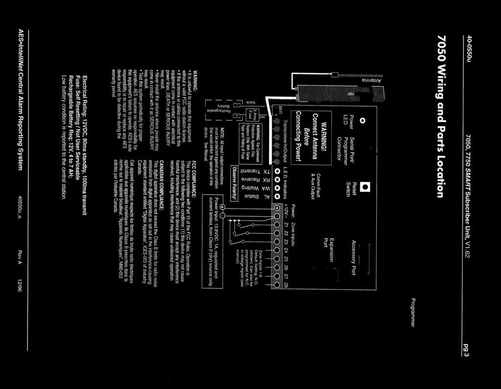
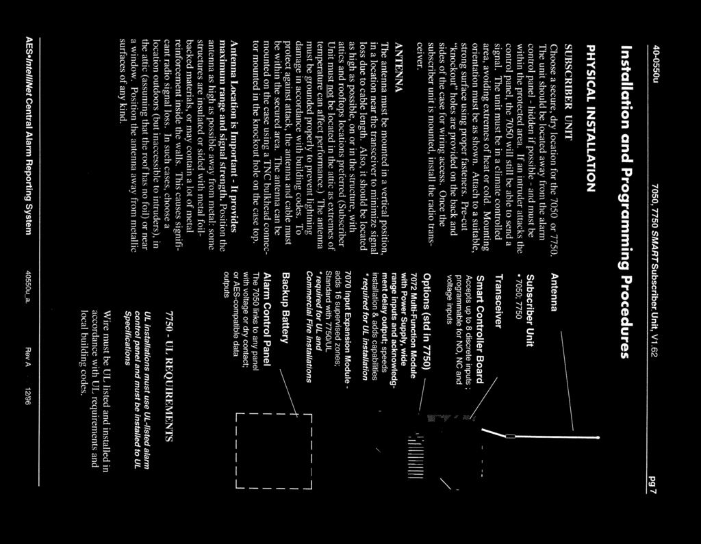
40 AES 7050-DLR Series RF Subscriber Unit Addendum to Installation and Operation Manual 1 Installation This section contains general information on the installation and wiring of an AES IntelliNet RF Subscriber Unit. 1.1 Overview The AES RF Subscriber Unit combines the electronics of an AES Subscriber unit, battery, a radio transceiver and any accessories into its enclosure. It is typically used to communicate alarm and status conditions of an alarm panel to a centrally located alarm monitoring facility via radio transmissions. A properly powered and configured AES Subscriber will communicate with an AES Central Receiver via a locally provided AES IntelliNet Network. 1.2 Physical Installation Guidelines Installation Guidelines. Refer to Diagrams in the original documentation. Choose a climate controlled, secure, and dry location for the subscriber unit. Avoid extremes of heat, cold, humidity, dust. Mount enclosure to a suitable, strong surface using appropriate fasteners for the weight of the unit and the surface on which it is being installed. Pre-cut knockout type holes are provided on the back and sides of the case for wiring access. Knockouts are sized for standard ½ inch conduit connectors. For burglar applications, the unit should be located away from the alarm panel hidden if possible and within the protected area. This will aid in the successful communication of the intrusion even if the alarm panel is compromised. The supplied case top tamper resistant Flexible 2.5db antenna can be mounted on the Subscriber s enclosure as shown in diagrams in original document. A remote external antenna can also be purchased separately and installed. Contact AES for additional information on our available antennas. A remote antenna should be mounted in a location near the transceiver to minimize inherent signal loss due to unnecessary cable length. Do not use longer coax than is needed to reach the antenna. Mount antenna as high as possible, on or in the structure, with attics and rooftop locations preferred. Height need not be higher than is required to overcome nearby obstructions to the signal path if any additional height would use a longer coax length. AES Corporation DLR-Add, Rev 0, 12/22/2008
41 AES 7050-DLR Series RF Subscriber Unit Addendum to Installation and Operation Manual Avoid installing the antenna in close proximity to other metal surfaces, as this may severely impact the performance of the radio communications due to the effects of signal reflections or detuning the antenna. o Remember that pipes, conduit, wiring, ductwork and other metal are commonly installed within walls and could affect performance. o Take into account foil backed insulation and wallpaper. o Metal objects may also be located in adjacent rooms or above ceilings. o Metallic framing is in common use today. Antenna should not be mounted directly over or in close proximity to metal studding. o Metallic supports are in common use today. Antenna should not be mounted in ceilings constructed of metal beams and supports that may interfere with the RF signal. The antenna must be grounded properly to help reduce damage due to surges produced by lightning. Grounding must be done in accordance with local building codes as well as those in accordance with any other authority having jurisdiction. When needed, use higher gain antenna with rated cable and connectors. Mount antenna as high as possible - attics can be ideal. Antenna must be mounted in a vertical orientation. To help protect against attack for burglary applications, the antenna and cable must be either secured or installed within the secure area. Avoid tightly coiled or bunched coax as this could also affect RF performance. Use Coax length that best fits the installation. NOTE: During installation, the subscriber unit attempts to enroll itself into an available AES-IntelliNet network and if successful generates signals at the central station. Central station operators must be forewarned to avoid a false alarm. 1.3 Affected Subscriber Models and Firmware Versions To determine if your Subscriber unit has the new features outlined in this Addendum, refer to the label on the large 40-pin chip on the main board of the Subscribers and compare to the chart below. Listed version and newer will have the new features DLR 7050-DLR Chip Label P/N 7050 V2.20 SUBDN Chip Label P/N 7050 SUBDN V AES AES Corporation DLR-Add, Rev 0, 12/22/2008
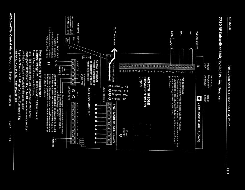
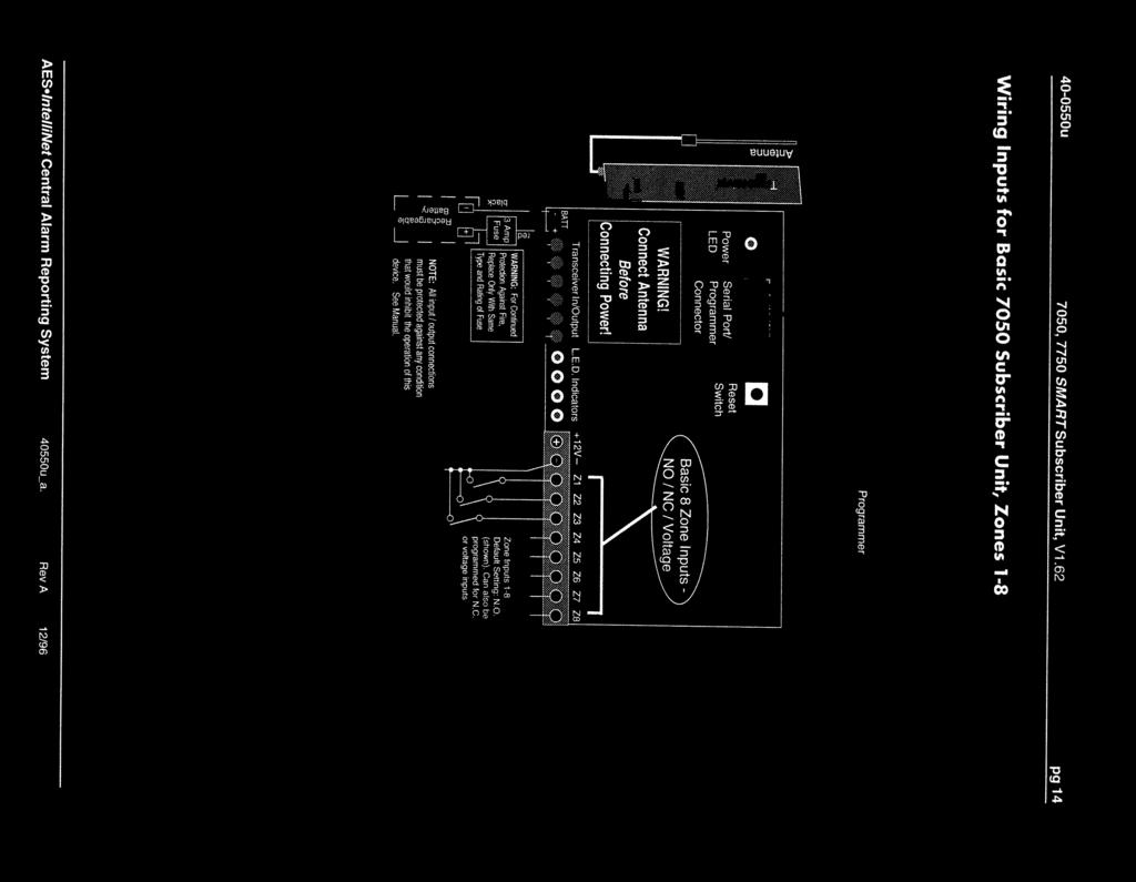
42 AES 7050-DLR Series RF Subscriber Unit Addendum to Installation and Operation Manual 2 Programming Since the release of version 1.62 the zone programming function was modified to operate similar to the functions in other newer releases of Subscriber firmware. In the 1.62 version a number had to be calculated and entered at the appropriate prompt to configure the zones. In the new format a single letter is entered to represent the desired programming for each specific zone or input. 2.1 Setup Unit Programming Unit ID and Cypher is as outlined in the manual except that the Enable Repeating Option does not follow the entry for DLR CODE. That function is located in Set Modes. 2.2 Set Check-In Time and Reporting Delay Period Programming Check-In and Reporting Delay Period is as outlined in manual. 2.3 Zone Programming The 7050-DLR zone inputs for zone 1-8 are located on the main circuit board and are wired at terminal block labeled TB1. Refer to the provided manual for wiring instruction. Zones 1-8 are N.O./N.C. inputs, which can be programmed for: N.O. / Normally Open, alarm on closed circuit or short N.C. / Normally Closed, alarm on open circuit Bypass, where the zone input is ignored. Zone Restorals: Each zone can be programmed to report Restoral to a normal state. The default setting is X for "No" Restorals. Factory default zone programming is set to (0) for N.O. and (X) for no Restoral. If this is satisfactory skip to the next section. To start, press programmer keys <CTRL>+<F3> (hold down the Control and the F3 keys at the same time). The following message appears: ZONE BANK 0. SET ZONE (BOC) B0 (available options) OLD OOOOOOOO LOW>HI (O, C or B = existing data) NEW... (Must enter exactly 8 values) The available and valid Zone programming options are shown in the parentheses on the display as shown above. The current programming is shown next to the word OLD, Zones 1-8 in order left to right. Your new entries will appear directly below and next to the word NEW. You must enter a valid letter for each of the 8 zones. Zones programming 1-8 can be set for: Entering more or less than 8 characters will result in repeating the above response. B - Bypassed O Normally Open. (alarm on short); C Normally Closed. (alarm on circuit open) AES Corporation DLR-Add, Rev 0, 12/22/2008
43 AES 7050-DLR Series RF Subscriber Unit Addendum to Installation and Operation Manual After successfully entering Set Zone data, the following appears: SET RESTORAL (XR)B0 (available options) OLD RRRRRRRR LOW>HI (R or X = existing data) NEW... (Must enter exactly 8 values) The option to select individual zones to report returning to a normal state is available. X = Restore Not Reported; R = Restore Reported. The existing or OLD programming is shown for each zone. Your new entries will appear directly below next to the word NEW. You must enter a valid letter X or R for each zone. Entering more or less than 8 characters will result in repeating the above response. When restore data entry is complete, Press <ENTER>. If data has been entered correctly, the following message appears: OK The zones are now programmed Programming must be completed within 65 seconds or function will: TIMEOUT 2.4 Set Modes Enable Repeating and Search Timestamp There are several functions that can be programmed in the Set Modes programming area. Repeating can be disabled and the unit can be programmed to search for time stamp in specialized system that use that feature. To Start, press programmer keys <CTRL> + <F4> (hold down the Control and the F4 keys at the same time). The following message appears: SET MODES--OLD: NEW ENABLE RPTNG-Y:. Enter Y to enable repeating capability. Default is Y. Press <ENTER> then the following appears: SRCH TIMESTA-N:. Enter Y/yes to enable the search of a time stamo, enter N/no (the default and setting) to disable the feature and allow normal reporting operation. Default is N. Press <ENTER>, If data has been entered correctly, the following message appears: OK If the programming in this function is not completed within 65 seconds the function will time-out. The Programmer will beep and the following message will be displayed: TIMEOUT AES Corporation DLR-Add, Rev 0, 12/22/2008
44 AES 7050-DLR Series RF Subscriber Unit Addendum to Installation and Operation Manual 2.5 Set Packet Time-To-Live Function In most cases the default settings will be appropriate. If so skip to this section. The Time to Live Function aborts old messages to ensure the efficient flow of data through the network. The old messages have typically been buffered, due to a network problem, but not yet sent. The default setting is usually adequate. In the default setting, test timer packets are assigned a 30-minute time to live. Any subscriber in possession of the packet that includes time to live data will be decrementing the timer. Any timer that reaches 0 will cause that packet to be removed from the transmit queue effectively aborting it. (Note: any 30-minute-old test timer message has already served its purpose. The central station should have recognized a missed check-in and flagged the event as a failure to test.) For more information, contact AES technical support To start, press programmer key F2. The following message appears: PACKET TIME TO LIVE CHKIN IN----OLD:NEW ENTER HRS----HH:.. Enter hours or accept displayed value by pressing <Enter> Next the following is diaplayed. ENTER HRS----HH:.. The above menu repeats for all available Packet Types, including STATUS, ALARM, and RESTORAL. AES Corporation DLR-Add, Rev 0, 12/22/2008
45 AES 7050-DLR Series RF Subscriber Unit Addendum to Installation and Operation Manual 3 Maintenance, Compliance, Warranty and Repair Once installed and normal operation is confirmed, there is typically little maintenance required. Monitoring the automatic test messages will confirm proper RF operation. Batteries should be periodically tested to be certain they have sufficient capacity to operate the system as needed. 3.1 Troubleshooting The most common causes of an RF failure or trouble are due to issues with the transmission line including but not limited to the antenna type, antenna location, coax, connectors, and transceiver. Antennas in close proximity to metal or with conductive material blocking or reflecting the transmitted signal would be at the top of the list. Observe the RX light on the main circuit board. If it is on steady or most of the time you may be receiving some RF or electrical interference. Try different locations for the antenna or use a remote long range RF antenna. Try replacing the transmission line components such as a new transceiver, coax and antenna. Problems on the circuit boards usually require returning the defective unit to AES for service. AES Corporation DLR-Add, Rev 0, 12/22/2008
7350 Integrated Transceiver Kit Installation and Operation Manual
 7350 Integrated Transceiver Kit Installation and Operation Manual AES Corporation 285 Newbury Street Peabody, MA 01960-1315 USA Tel 978 535-7310 Fax 978 535-7313 www.aes-intellinet.com Copyright 2005 All
Transmitter. User Manual. Firmware version 1.0 and greater
 ProRF SPC Transmitter User Manual Firmware version 1.0 and greater FCC NOTICE This equipment has been tested and found to comply with the limits for a class B digital device, pursuant to part 15 of the
INSTALLATION INSTRUCTIONS
 INSTALLATION INSTRUCTIONS K4460V2 3/01 6150RFPL2 Keypad/Transceiver About the 6150RFPL2 The 6150RFPL2 is a combination unit that contains: A 6150PL2 Fixed Addressable Keypad A 5800TM Transmitter Module
AES 7705i MultiNet Receiver System Initial Installation and Setup Guide
 AES 7705i MultiNet Receiver System Initial Installation and Setup Guide AES Corporation 285 Newbury Street. Peabody, Massachusetts 01960-1315 USA Tel: USA (978) 535-7310. Fax: USA (978) 535-7313 Copyright
INSTALLATION AND SETUP GUIDE
 INSTALLATION AND SETUP GUIDE K4460V3 4/06 Rev A 6150RFPL2 Keypad/Transceiver GENERAL INFORMATION The 6150RFPL2 Keypad/Transceiver is a combination unit incorporating a normally-open relay output and the
Instruction Manual MX-485-S Bi-directional RS485 Data Transceiver
 Instruction Manual MX-485-S Bi-directional RS485 Data Transceiver Copyright 2005, American Fibertek, Inc. 1020JD Table of Contents Functional Description...3 Installation...3 Power Source...3 Power Connection...3
INSTALLATION INSTRUCTIONS
 INSTALLATION INSTRUCTIONS K4456V1 8/00 FA260RF Keypad/Transceiver About the FA260RF The FA260RF is a combination unit that contains: A FA260KP Fixed Addressable Keypad A 5800TM Transmitter Module A 5881M
VOLUME CONTROL CONNECTION TERMINAL
 INSTALLATION & USER GUIDE For Parallel Signal Distribution to Multiple Volume Controls VOLUME CONTROL CONNECTION TERMINAL V-T8 V-T8 VOLUME CONTROL CONNECTION TERMINAL TABLE OF CONTENTS Features...1 Product
User s Guide Instructions for Installation and Operation
 User s Guide Instructions for Installation and Operation 2.4 GHZ SPREAD SPECTRUM REMOTE CONTROLS Keyfob Transmitters Models KTX24SS1 KTXW24SS3 KTX24SS2 KTX24SS3 Wall Mount Models NTX24SS1 NTX24SS2 Remote
7788F RF Subscriber Unit Installation and Operation Manual
 7788F RF Subscriber Unit Installation and Operation Manual AES Corporation 285 Newbury Street Peabody, MA 01960-1315 USA Tel (978) 535-7310 Fax (978) 535-7313 www.aes-intellinet.com Copyright 2016 All
ACT-IR220Li/220LN IrDA Serial Port Adapter
 ACT-IR220Li/220LN IrDA Serial Port Adapter Product Specification Summary ACTiSYS Corp. 48511 Warm Springs Blvd, Suite 206 Fremont, CA 94539, USA TEL: (510) 490-8024, FAX: (510) 623-7268 E-Mail: irda-support@actisys.com
USER MANUAL MODEL Time Division Multiplexor, RS-232 (CTS TDM-V.24) SALES OFFICE (301) TECHNICAL SUPPORT (301)
 SALES OFFICE (301) TECHNICAL SUPPORT (301)") USER MANUAL MODEL 3042 (CTS TDM-V.24) Time Division Multiplexor, RS-232 Part #: 07M3042-A Doc #: 119001UA Revised 3/26/01 SALES OFFICE (301) 975-1000 TECHNICAL SUPPORT (301) 975-1007 1.0 WARRANTY INFORMATION
USER MANUAL MODEL 3042 (CTS TDM-V.24) Time Division Multiplexor, RS-232 Part #: 07M3042-A Doc #: 119001UA Revised 3/26/01 SALES OFFICE (301) 975-1000 TECHNICAL SUPPORT (301) 975-1007 1.0 WARRANTY INFORMATION
Series 500. Owner s Manual. Analog Transmitters by Data Industrial. Data Industrial. Data Industrial 2/95 PN 72806
 Series 500 Analog Transmitters by Data Industrial Data Industrial Owner s Manual Data Industrial 2/95 PN 72806 Table of Contents Introduction... 1 4-20 ma Loop Supply Requirements... 2 Installation...
For Precise Volume Adjustment with Programmable Muting in Any Room
 INSTALLATION & USER GUIDE For Precise Volume Adjustment with Programmable Muting in Any Room 12 STEP MUTING WALL MOUNT VOLUME CONTROL V-12M V-12M 12 STEP MUTING WALL MOUNT VOLUME CONTROL TABLE OF CONTENTS
SCADA and Telemetry Solutions. SCADALink IO900. Modular Wireless I/O System. User Manual Version V1.3 for SCADALink IO900 BENTEK SYSTEMS LTD
 Modular Wireless I/O System User Manual Version V. for BENTEK SYSTEMS LTD #, 0 Ave S.E. Calgary, AB, Canada TB 0L Ph:(0) Fax:(0) email: sales@scadalink.com web: The is a Modular Wireless I/O System that
Instruction Manual MX-480 Bi-directional Multi-Protocol Data
 Instruction Manual MX-480 Bi-directional Multi-Protocol Data Copyright 2007, American Fibertek, Inc. 1210JD Table of Contents Functional Description...3 Installation...3 Power Source...3 Power Connection...4
JMAA-3600HR16-UL. Installation and Operation Instructions. Performance Series 360w RMS 4-Channel Amplifier Kit For Harley RoadGlide Ultra
 Performance Series 360w RMS 4-Channel Amplifier Kit For 2016-2018 Harley RoadGlide Ultra # JMAA-3600HR16-UL 2017 J&M Corporation. All rights reserved. 9/17 Installation and Operation Instructions Product
X80 Activator. User's Manual. Version 1.1.
 X80 Activator User's Manual Version 1.1 www.buckeyecam.com Table of Contents 1. Warnings... 3 2. Overview... 4 3. Getting Started... 5 4. Using the Activate Button... 7 5. Wiring... 8 6. Specifications...
CONNECT SYSTEMS INCORPORATED 1802 Eastman Ave., Suite 116 Ventura, Ca FLEX SERIES UNIVERSAL CONTROLLER
 CONNECT SYSTEMS INCORPORATED 1802 Eastman Ave., Suite 116 Ventura, Ca. 93003 Phone (805) 642-7184 Fax (805) 642-7271 FLEX SERIES UNIVERSAL CONTROLLER SIMPLEX REPEATER MIX With Voice Prompts User s Instruction
ACT-IR220L/LE IrDA Serial Port Adapter
 ACT-IR220L/LE IrDA Serial Port Adapter Product Specification Summary ACTiSYS Corp. 48511 Warm Springs Blvd, Suite 206 Fremont, CA 94539, USA TEL: (510) 490-8024, FAX: (510) 623-7268 E-Mail: irda-support@actisys.com
14 CHANNEL FAMILY RADIO SYSTEM MODEL # FR142
 14 CHANNEL FAMILY RADIO SYSTEM MODEL # FR142 2001 Audiovox Electronics Corp., Hauppauge, NY 11788 Printed in China 128-6020 052FR142104 BEFORE OPERATING THIS PRODUCT PLEASE READ THESE INSTRUCTIONS COMPLETELY
MIRAGE BD-38-G DUAL BAND POWER AMPLIFIER
 MIRAGE BD-38-G DUAL BAND POWER AMPLIFIER MIRAGE BD-38-G Dual Band Amplifier INTRODUCTION: The Mirage BD-38-G is a 80/60 watt dual band power amplifier for use with today's dual band handie talkies operating
M-4KP/M-10KP. For Enhanced Control of a Multizone System/ for Controlling Four Sources in a Multizone System INSTALLATION & USER GUIDE
 INSTALLATION & USER GUIDE For Enhanced Control of a Multizone System/ for Controlling Four Sources in a Multizone System FOUR SOURCE MULTIZONE KEYPAD/ TEN KEY MULTIZONE KEYPAD M-4KP/M-10KP M-4KP/M-10KP
SAT SCD/ARGOS INSTRUCTION MANUAL
 INSTRUCTION MANUAL REVISION: 1/03 COPYRIGHT (c) 2000-2003 CAMPBELL SCIENTIFIC, INC. This is a blank page. WARRANTY AND ASSISTANCE This equipment is warranted by CAMPBELL SCIENTIFIC (CANADA) CORP. ( CSC
VideoEase VGA 1x4 Distribution Hub (500150, ) Installation Guide
 Installation Guide") VideoEase VGA 1x4 Distribution Hub (500150, 500151) Installation Guide P/N: 94-000624-A SE-000605-A Table of Contents 1. Overview...3 1.1. Description...3 1.2. Features...4 2. Technical Specifications...5
VideoEase VGA 1x4 Distribution Hub (500150, 500151) Installation Guide P/N: 94-000624-A SE-000605-A Table of Contents 1. Overview...3 1.1. Description...3 1.2. Features...4 2. Technical Specifications...5
Gypsy Statement of Limited Warranty. Part 1 General Terms
 Gypsy Statement of Limited Warranty Part 1 General Terms This Statement of Limited Warranty includes Part 1 General Terms, and Part2 Warranty Information. The warranties provided by PROVO CRAFT AND NOVELTY,
PTT- Z or PTT-U PUSH-TO-TALK Specification
 Federal Communication Commission Interference Statement This equipment has been tested and found to comply with the limits for a Class B digital device, pursuant to Part 15 of the FCC Rules. These limits
Installation and Operation Manual MSI. Multi-Sensor Interface Hub. Interface Module for all Sensors Network and Wireless CAUTION
 Installation and Operation Manual MSI Multi-Sensor Interface Hub Interface Module for all Sensors Network and Wireless CAUTION This equipment complies with the limits for a Class B digital device, pursuant
Rough-In Frame OVERVIEW OF INSTALLATION PROCEDURE PLANNING GUIDE MODEL IR-105 INSTALLATION DON'TS
 Rough-In Frame MODEL IR-105 INSTALLATION INSTRUCTIONS READ & SAVE THESE INSTRUCTIONS Model IR-105 Rough-In Frame is to be used with NuTone Model IM-4406 Series Radio/CD Player/Intercom Master Unit. This
AMERITRON RCS-12 AUTOMATIC ANTENNA SWITCH
 AMERITRON RCS-12 AUTOMATIC ANTENNA SWITCH INSTRUCTION MANUAL PLEASE READ THIS MANUAL BEFORE OPERATING THIS EQUIPMENT! 116 Willow Road Starkville, MS 39759 USA 662-323-8211 Version 3B Printed in U.S.A.
LPU-2127 User Manual
 LPU-2127 User Manual Doc #9004169 Rev A1, 04/15 Table of Contents Introduction... iii Warranty and Warranty Restrictions... iv Chapter 1: Specifications and Options... 1 Dimensions...1 Specifications...
GM8036 Laser Sweep Optical Spectrum Analyzer. Programming Guide
 GM8036 Laser Sweep Optical Spectrum Analyzer Programming Guide Notices This document contains UC INSTRUMENTS CORP. proprietary information that is protected by copyright. All rights are reserved. This
Firmware Version d & higher Installation & Operation
 DIGI LCD Readout Firmware Version d 2.100 & higher Installation & Operation Warranty Accurate Technology, Inc., warrants this product against defective parts and workmanship for 1 year commencing from
Performance Series 360w Amplifier Kit For Harley RoadGlide with Lower/Rear Speakers JMAA-3600HR15-RC
 Performance Series 360w Amplifier Kit For 2015-2018 Harley RoadGlide with Lower/Rear s # JMAA-3600HR15-RC 2017 J&M Corporation. All rights reserved. 9/17 Installation and Operation Instructions Product
ProScale. Compact LCD Readout. Installation & Operation
 ProScale Compact LCD Readout Installation & Operation WARRANTY Accurate Technology, Inc. warrants the ProScale Measurement Systems against defective parts and workmanship for 1 year commencing from the
ProScale Compact LCD Readout. Operation. Firmware version C 2.xxx and higher
 ProScale Compact LCD Readout Operation Firmware version C 2.xxx and higher WARRANTY Accurate Technology, Inc., warrants this product against defective parts and workmanship for 1 year commencing from the
Mirage B-320-G FEATURES
 Mirage B-320-G The Mirage B-320-G is a VHF power amplifier designed for 2 meters covering 144-148 MHz. The Hi and Lo input selector switch makes this amp useable for both handheld and mobile transceivers.
supplied o-ring grease can be used to hold the o-ring in the groove during installation.
 42GOXX16A4-XT-1-1 ANTENNA GUIDE OM-20000158 Rev 1 December 2013 The 42G1215A-XT-1 is an active GPS antenna that receives the GPS L1 1575.42 MHz frequency, the GLONASS L1 1602 1626 MHz frequencies, the
Wireless Transceiver (TRV)
") Installation and Operation Manual Wireless Transceiver (TRV) For Platinum Controls with Communication WARNING This equipment complies with the limits for a Class B digital device, pursuant to Part 15 of
Installation and Operation Manual Wireless Transceiver (TRV) For Platinum Controls with Communication WARNING This equipment complies with the limits for a Class B digital device, pursuant to Part 15 of
Installation Instructions Hustler Collinear Two Meter Fixed Station Antenna Master Gainer Model G6-144B
 Installation Instructions Hustler Collinear Two Meter Fixed Station Antenna Master Gainer Model Warning INSTALLATION OF THIS PRODUCT NEAR POWER LINES IS DANGEROUS. FOR YOUR SAFETY, FOLLOW THE INSTALLATION
Instruction Manual MTX-8485C MRX-8485C Four Channel Video Multiplexer with Bi-directional Data
 Instruction Manual MTX-8485C MRX-8485C Four Channel Video Multiplexer with Bi-directional Data Copyright 2005, American Fibertek, Inc. 1027JD Table of Contents Functional Description...3 Installation...3
o-ring grease can be used to hold the o-ring in the groove during installation.
 42G1215A-XT-1 ANTENNA GUIDE OM-20000152 Rev 1 December 2013 The 42G1215A-XT-1 is an active antenna designed to operate at the GPS L1 and L2 frequencies, 1575.42 and 1227.60 MHz. The antenna is aircraft
o-ring grease can be used to hold the o-ring in the groove during installation.
 42G1215A-XT-1-2 and 42G1215A-XT-1-3 ANTENNA GUIDE OM-20000154 Rev 1 December 2013 The 42G1215A-XT-1-3 and 42G1215A-XT-1-2 are active antennas designed to operate at the GPS L1 and L2 frequencies, 1575.42
User s Guide ASSISTIVE LISTENING SYSTEMS
 User s Guide ASSISTIVE LISTENING SYSTEMS 2 Digital-1 User s Guide Contents How to use Digital-1...3 Tuning...6 Frequency Chart...8 Correcting Interference...9 Recharging...10 Specifications...12 Notice...13
Using the USB Output Port to Charge a Device
 Table of Contents ----------------------------------- 2 Features ----------------------------------------------- 3 Controls and Functions ---------------------------------- 4 ER210 Power Sources -----------------------------------
Instruction Manual MT-945SL Four Channel Video Transmitter With Two Bi-Directional Data Channels
 Instruction Manual MT-945SL Four Channel Video Transmitter With Two Bi-Directional Data Channels Copyright 2006, American Fibertek, Inc. 0307JD Table of Contents Functional Description... 3 Installation...
AES Central Station. INCLUDING: 7000/2 Dual Receiver 7100 Network Controller 7030 Transceiver INSTALLATION & OPERATION MANUAL
 AES Central Station INCLUDING: 7000/2 Dual Receiver 7100 Network Controller 7030 Transceiver INSTALLATION & OPERATION MANUAL TRANSMIT RECEIVE WAIT TRANSMIT RECEIVE WAIT SELECT POWER FAULT 1 FAULT 2 A B
Model 935A. Dual Tone Sender INSTRUCTION MANUAL
 Model 935A Dual Tone Sender INSTRUCTION MANUAL Monroe Electronics 100 Housel Ave Lyndonville NY 14098 800-821-6001 585-765-2254 fax 585-765-9330 monroe-electronics.com Printed in USA Copyright Monroe Electronics,
TARGETuner Antenna Management System for Screwdriver Antennas
 TARGETuner Antenna Management System for Screwdriver Antennas www.westmountainradio.com 1020 Spring City Drive Waukesha, WI 53186 262-522-6503 sales@westmountainradio.com 2014, All rights reserved. All
S-4VC/S-6VC. For Connecting Four/Six Pairs of Speakers to an Amplifier or Receiver, with Precise Volume Adjustment in any Zone
 INSTALLATION & USER GUIDE For Connecting Four/Six Pairs of Speakers to an Amplifier or Receiver, with Precise Volume Adjustment in any Zone SPEAKER SELECTORS WITH VOLUME CONTROLS S-4VC/S-6VC S-4VC / S-6VC
GTX 320A. Mode A/C Transponder. pilot s guide
 GTX 320A Mode A/C Transponder pilot s guide 2000 GARMIN Corporation GARMIN International, Inc. 1200 East 151 st Street, Olathe, Kansas 66062, U.S.A. Tel. 913/397.8200 or 800/800.1020 Fax 913/397.8282 GARMIN
User Manual. ProRF Encoder Transmitter & Receiver
 User Manual ProRF Encoder Transmitter & Receiver WARRANTY Accurate Technology, Inc. warrants the ProScale Systems against defective parts and workmanship for 1 year commencing from the date of original
Broadband Step-Up Transformer. User Manual
 Broadband Step-Up Transformer User Manual 990-1930 09/2004 Introduction Introduction About this unit The APC Step-Up Transformer provides 220 V power from 60 VAC Broadband cable systems. Safety Electrical
JAMP-700HR15-RCP. Installation and Operation Instructions. ROKKER XXRP 700w Amplifier Kit For Harley RoadGlide with Lower/Rear Speakers
 ROKKER XXRP 700w Amplifier Kit For 2015-2018 Harley RoadGlide with Lower/Rear s # JAMP-700HR15-RCP 2018 J&M Corporation. All rights reserved. 4/18 Installation and Operation Instructions Product Overview
Signal Isolation Module. Instruction Manual SIM
 Signal Isolation Module Instruction Manual SIM200-000 Table of Contents 1. General Description... 3 2. Specifications... 3 2.1 Electrical... 3 2.2 Physical... 4 3. Installation... 4 3.1 Wiring Guidelines...
CDT. Service and Installation Manual. Manual Revision Oct 2014
 CDT Service and Installation Manual Manual Revision Oct 2014 2014 Cimarron Technologies Corp., Escondido, CA, USA. All rights reserved. No part of this manual may be reproduced in any way without the express
USER MANUAL MODEL Parallel to Serial/ Serial to Parallel Interface Converter
 USER MANUAL MODEL 2029 Parallel to Serial/ Serial to Parallel Interface Converter C E R T I F I E D An ISO-9001 Certified Company Part #07M2029-B, Rev. C Doc. #102011UB Revised 6/16/09 SALES OFFICE (301)
FA401 Single Transmitter / Single Output Receiver. FA401R Single Transmitter / Single Relay Output Receiver. Installation Instructions 02305C
 FA401 Single Transmitter / Single Output Receiver FA401R Single Transmitter / Single Relay Output Receiver Frequency Agile 900MHz Installation Instructions 02305C Note: The FA401 is intended to be installed
Instruction Manual. KP-1 Series 10M, 6M, 2M, 1-1/4M, 70 CM. IN-SHACK GaAsFET PRE-AMPLIFIER. MIRAGE KP-1 Pre-Amplifier
 Instruction Manual IN-SHACK GaAsFET PRE-AMPLIFIER KP-1 Series 10M, 6M, 2M, 1-1/4M, 70 CM Version A Copyright 1996, MIRAGE Communications Before operating this unit, please read these instructions completely.
RFTX-1 Installation Manual
 RFTX-1 Installation Manual complete control Universal Remote Control RFTX-1 Installation Manual 2009-2014 Universal Remote Control, Inc. The information in this Owner s Manual is copyright protected. No
PRX4SERL Four Zone Receiver Decoder
 PRX4SERL Four Zone Receiver Decoder Operating Manual Microframe Corporation 604 S. 12 th Street Broken Arrow, OK 74012 Tel: (918) 258-4839 Toll Free: 1-800-635-3811 Website: www.microframecorp.com E-mail:
Where to Obtain More Information
 BCI25D 10/10/2 4:33 PM Page 1 General Explanation of BCi25D The BCi25D is an APCO Project 25 Digital Card that enables you to monitor APCO Project 25 Systems. When the BCi25D card is installed into either
SIR-WRR1. User's Guide SIRIUS Echo Antenna. Signal Repeater System Accessory
 SIR-WRR1 User's Guide SIRIUS Echo Antenna Signal Repeater System Accessory Desktop SIRIUS Docking Echo Station Antenna FCC NOTICE: This device complies with part 15 of the FCC Rules and with RSS-210 of
JMAA-1800HR15. Installation and Operation Instructions. 180w Performance Series Amplifier Kit For Harley RoadGlide/ Ultra
 180w Performance Series Amplifier Kit For 2015-2018 Harley RoadGlide/ Ultra # JMAA-1800HR15 2017 J&M Corporation. All rights reserved. 9/17 Installation and Operation Instructions Product Description This
Preliminary Data Sheet!
 HELLROARING TECHNOLOGIES, INC. P.O. BOX 1521 POLSON, MT 59860 406 883-3801 HTTP://WWW.HELLROARING.COM SALES11@HELLROARING.COM SSD-100200-1200V-XP-XC Preliminary Data Sheet! The SSD-100200-1200V-XP-TTL
Warranty Terms & Conditions
 Warranty Terms & Conditions Is my guitar under warranty? How long, what specific parts? Ibanez Electric Guitars and Basses Limited Warranty Ibanez Electric Guitars and Basses sold in the United States
High Performance Microphone Splitter. Artcessories. User's Manual
 High Performance Microphone Splitter Artcessories User's Manual IMPORTANT SAFETY INSTRUCTION READ FIRST This symbol, whenever it appears, alerts you to the presence of uninsulated dangerous voltage inside
NCS-C150 INSTRUCTION MANUAL Rev A. Collcomm Inc. Shipping Address 2310 Pendley Road Cumming, Georgia 30041
 NCS-C150 INSTRUCTION MANUAL Rev A Collcomm Inc. d.b.a. NCS Shipping Address 2310 Pendley Road Cumming, Georgia 30041 Mailing Address 1595 Peachtree Parkway Suite 204-123 Cumming, Georgia 30041 Toll Free
COMMERCIAL TRANSMITTER INSTRUCTIONS
 READ THIS MANUAL CAREFULLY BEFORE BEGINNING COMMERCIAL INSTRUCTIONS MODELS: 831, 8833 OCS: 1-DOOR 733, 8833C OCS: 3-DOOR 639: 9-DOOR 535: 27-DOOR PRODUCT FEATURES Allstar Commercial Transmitters are designed
User s Guide Instructions for Installation and Operation
 User s Guide Instructions for Installation and Operation This page intentionally left blank. 2.4 GHZ SPREAD SPECTRUM REMOTE CONTROLS Handheld Transmitter Model KTXW24SSA1 KTXW24SSA2 KTXW24SSA4 KTXW24SSA6
Instruction Manual MTX-8485 MRX-8485 Four Channel Video Multiplexer with Bi-directional Data
 Instruction Manual MTX-8485 MRX-8485 Four Channel Video Multiplexer with Bi-directional Data Copyright 2003, American Fibertek, Inc. 0530JD Table of Contents 2 Functional Description... 4 Installation...
SAT ARGOS INSTRUCTION MANUAL
 INSTRUCTION MANUAL 7/01 COPYRIGHT (c) 2000-2001 CAMPBELL SCIENTIFIC, INC. This is a blank page. Warranty and Assistance The is warranted by CAMPBELL SCIENTIFIC, INC. to be free from defects in materials
Everything will be securely inserted inside the box so items do not shift during shipping and handling. Rev D 2
 Installation Guide Shipping Box Contains Everything that is included in the box being shipped to should contain the following items: Receiver Assembly Documentation on CD ROM Tags, if placed in the same
f i r e - p a r t s. c o m
 Model: CON 1001-1 INSTALLATION AND OPERATING INSTRUCTIONS SINGLE-FUNCTION WIRELESS REMOTE CONTROL SYSTEM FOR OPERATING VALVES WITH ON/OFF LATCHING SOLENOIDS IF YOU CANNOT READ OR UNDERSTAND THESE INSTALLATION
Installation and Operating Manual. (version 4.05) AAS Access Control Station. Your Partner in Access Control
 AAS Access Control Station. Your Partner in Access Control") Installation and Operating Manual (version 4.05) AAS 11-3500 Access Control Station Your Partner in Access Control www.americanaccess.com Contents PARTS CHECKLIST4 INTRODUCTION 5 SETTING THE SYSTEM (FACILITY)
Installation and Operating Manual (version 4.05) AAS 11-3500 Access Control Station Your Partner in Access Control www.americanaccess.com Contents PARTS CHECKLIST4 INTRODUCTION 5 SETTING THE SYSTEM (FACILITY)
SYSTEM OPERATING CONTROLS
 SYSTEM OPERATING CONTROLS Master Station Controls 1 END CALL: Ends intercom communication and returns system to audio source. 2 DOOR TALK: Initiates intercom communication to the door speakers. 3 INSIDE/PATIO:
NCS-C150 INSTRUCTION MANUAL Rev D. Collcomm Inc. d.b.a. NCS. Shipping Address 2310 Pendley Road Cumming, Georgia 30041
 NCS-C150 INSTRUCTION MANUAL Rev D Collcomm Inc. d.b.a. NCS Shipping Address 2310 Pendley Road Cumming, Georgia 30041 Mailing Address 1595 Peachtree Parkway Suite 204-123 Cumming, Georgia 30041 Toll Free
Copyright Teletronics International, Inc. Patent Pending
 Copyright 2003 By Teletronics International, Inc. Patent Pending FCC NOTICES Electronic Emission Notice: This device complies with Part 15 of the FCC rules. Operation is subject to the following two conditions:
AIU-2 Installation Manual
 AIU-2 Installation Manual RESEARCH CONCEPTS INC. 9501 Dice Lane Lenexa, Kansas 66215 USA VOICE: (913) 422-0210 FAX: (913) 422-0211 www.researchconcepts.com support@researchconcepts.com Contents subject
INSTALLATION GUIDE. Video Balun Transceiver with fixed BNC for twisted pair operation with other balun transceivers or active receivers.
 INSTALLATION GUIDE VB37M Video Balun Transceiver for Twisted Pair Description Video Balun Transceiver with fixed BNC for twisted pair operation with other balun transceivers or active receivers. The VB37M
User s Guide FM Transmitter
 TM 12-634 User s Guide FM Transmitter Please read this user s guide before using your new FM Transmitter. 12-634_en.indd 1 Package contents FM Transmitter USB Cable User s Guide Quick Start IMPORTANT SAFETY
MODEL UBP-10 UNIVERSAL IN-LINE TRANSDUCER AMPLIFIER BI-POLAR SUPPLY, 0-10 VOLT OUTPUT
 MODEL UBP-10 UNIVERSAL IN-LINE TRANSDUCER AMPLIFIER BI-POLAR SUPPLY, 0-10 VOLT OUTPUT 2080 Arlingate Lane, Columbus, Ohio 43228 (614) 850-5000 Sensotec, Inc. 2080 Arlingate Lane Columbus, Ohio 43228 Copyright
Distribution Amplifiers 1
 Distribution Amplifiers 1-30dB PUT 49-750 MHz 43 db GA POWER DOUBLED P/N: 1002705 REVERSE GA M MAX DESCRIPTION The R.L. DRAKE models DA8642, DA8632,, and DA7533, are broadband distribution amplifiers designed
MedRx Avant Polar HIT AH-I-MPHITS-5 Effective 11/07/11
 INSTALLATION MANUAL 2 Contents Getting To Know Your AVANT POLAR HIT TM... 4 Setting up the System... 6 Software Installation... 7 Driver Installation Windows 7... 10 Driver Installation Windows XP... 13
Instruction Manual RT-93285SL RR-93285SL Thirty-two Channel Video Multiplexer With Two Bi-directional Data Channels
 Instruction Manual RT-93285SL RR-93285SL Thirty-two Channel Video Multiplexer With Two Bi-directional Data Channels Copyright 2006, American Fibertek, Inc. 0222JD Table of Contents Functional Description...3
Installation & User Guide. For Powering Distributed Audio Systems A45-X2 TWO CHANNEL AMPLIFIER
 Installation & User Guide For Powering Distributed Audio Systems TWO CHANNEL AMPLIFIER A45-X2 A45-X2 TWO CHANNEL AMPLIFIER TABLE OF CONTENTS Features...1 Product Overview...2 Package Contents...4 Preparing
Instruction Sheet REB SERIES. Rotating Sliding Base REB18
 Instruction Sheet REB SERIES Rotating Sliding Base REB14 REB18 THANK YOU Thank you for purchasing the REB Series Rotating Sliding Base. Please read these instructions thoroughly before installing this
installation guide XMFM1
 installation guide XMFM1 Important: This manual contains important safety and operating information. Please read, understand, and follow the instructions in this manual. Failure to do so could result in
Digi-Fence. User Manual (all models) For All Models with Digital Readout Firmware version d & Higher
 For All Models with Digital Readout Firmware version d & Higher") Digi-Fence User Manual (all models) For All Models with Digital Readout Firmware version d 2.000 & Higher Warranty Accurate Technology, Inc., warrants this product against defective parts and workmanship
Digi-Fence User Manual (all models) For All Models with Digital Readout Firmware version d 2.000 & Higher Warranty Accurate Technology, Inc., warrants this product against defective parts and workmanship
USER MANUAL. MODEL 2017A RS-232 to 20ma Current Loop Converter. SALES OFFICE (301) TECHNICAL SUPPORT (301)
 TECHNICAL SUPPORT (301)") USER MANUAL MODEL 2017A RS-232 to 20ma Current Loop Converter Part# 07M2017A-A Doc# 073021UA Revised 10/15/93 SALES OFFICE (301) 975-1000 TECHNICAL SUPPORT (301) 975-1007 http://www.patton.com 1.0 WARRANTY
USER MANUAL MODEL 2017A RS-232 to 20ma Current Loop Converter Part# 07M2017A-A Doc# 073021UA Revised 10/15/93 SALES OFFICE (301) 975-1000 TECHNICAL SUPPORT (301) 975-1007 http://www.patton.com 1.0 WARRANTY
Radio Remote Controls Manual K Series
 Radio Remote Controls Manual K Series PN 52764 2010.12.20 Rev. 2 K Series radio control manual 1 Conductix Incorporated The technical data and images which appear in this manual are for informational purposes
Table of Contents. Safety Notices
 IM0081 2018-01 Table of Contents Product Overview... 3 Principle of Operation... 3 Closed-Loop Servo Control with the FC-24 Controller... 4 Adjustments... 5 LED Status Indicators... 6 Installation...7
Installation Instructions
 J&M STAGE-5 ROKKER XXR Custom 700w Amplifier Installation Kit for 2015-19 Harley Roadglide CVO Ultra # JAMP-700HR15-ULP-CVO 2019 J&M Corporation. All rights reserved. 4/19 Installation Instructions Product
af i Instruction Manual MR-944C Four Channel Video Receiver With One Bi-Directional Multi-Protocol Data Channel american fibertek 11/30/2012 JPK
 af i american fibertek Instruction Manual MR-944C Four Channel Video Receiver With One Bi-Directional Multi-Protocol Data Channel 11/30/2012 JPK Table of Contents Functional Description... 3 Installation...
A-16D A-Net Distributor
 A-16D A-Net Distributor For use with the Personal Monitor Mixing System Information in this document is subject to change. All rights reserved. Copyright 2003 Aviom, Inc. Printed in USA Document Rev. 1.03
Driveway Alarm INSTALLATION MANUAL
 WIRELESS ACCESS CONTROLS Driveway Alarm INSTALLATION MANUAL Mounting post Transmitter Receiver Transformer Sensor Kit Includes: Transmitter Module Sensor Receiver Transformer Mounting post (3 pieces) Installation
LV-1K Line Verification Panel with Key Switch
 Designed, Manufactured and Supported in the USA VIKING PRODUCT MANUAL COMMUNICATION & SECURITY SOLUTIONS LV-1K Line Verification Panel with Key Switch October 30, 2013 Line Verification Panel with Key
IRRIGATION 810-T PLUS TRANSMITTER GUIDE
 IRRIGATION 810-T PLUS TRANSMITTER GUIDE Pg. 2 HOT SHOT OVERVIEW 3 BASIC WIRING INSTRUCTIONS 4 HOW TO CONTROL AND SHARE MULTIPLE WELLS 5 TRANSMITTER FUNCTION SWITCH SETTINGS 5 LED INDICATORS 5 OPERATING
Digi-Stop. Installation & Operation
 Digi-Stop Installation & Operation WARRANTY Accurate Technology, Inc. warrants the ProScale Systems against defective parts and workmanship for 1 year commencing from the date of original purchase. Upon
Technical Support, End User License & Warranty Information
 Technical Support, End User License & Warranty Information How to get Technical Support Pazzles provides free Technical Support for your Inspiration Vūe for a period of 1 year from the date of purchase.