Lectures on Wireless Networks & Mobile Computing. Lecture 1
|
|
|
- Debra Franklin
- 6 years ago
- Views:
Transcription


1 Lectures on Wireless Networks & Mobile Computing Lecture 1 1
2 Agenda Introduction on Mobile Computing & Wireless Networks Wireless Networks - Physical Layer IEEE MAC Wireless Network Measurements & Modeling Location Sensing Performance of VoIP over wireless networks Mobile Peer-to-Peer computing 2
3 General Objectives Build some background on wireless networks, IEEE802.11, positioning, mobile computing Explore some research projects and possibly research collaborations 3
4 Wireless Networks & Mobile Computing Lecture on Introduction on Mobile Computing 4
5 Profound technologies The most profound technologies are those that disappear. They weave themselves into the fabric of everyday life until they are indistinguishable from it." Mark Weiser,
6 Weiser s vision The creation of environments saturated with computing and communication capability yet gracefully integrated with human users After two decades of hardware progress, many critical elements of pervasive computing that were exotic in 1991 are now viable commercial products: handheld and wearable computers, wireless LANs, and devices to sense and control appliances Well-positioned to begin the quest for Weiser's vision 6
7 Constraints in Pervasive Computing The most precious resource in a computer system is no longer its processor, memory, disk or network. Rather, it is a resource not subject to Moore's law: User Attention Today's systems distract a user in many explicit & implicit ways, thereby reducing his effectiveness. 7
8 Pervasive computing Pervasive computing is the method of enhancing computer use by making many computers available throughout the physical environment but effectively invisible to the user. 8
9 Pervasive computing (cont d) Pervasive computing spaces involve autonomous networked heterogeneous systems operating with minimum human intervention 9

10 Monitoring the environment Source: Joao Da Silva s talk at Enisa, July 20 th, 2008


11 Tagged products Source: Joao Da Silva s talk at Enisa, July 20th, 2008

12 Source: Joao Da Silva s talk at Enisa, July 20th, 2008

13 Source: Joao Da Silva s talk at Enisa, July 20th, 20

14 New networking paradigms for efficient search and sharing mechanisms Source: Joao Da Silva s talk at Enisa, July 20th, 20
15 15
16 16
17 17

18 18
19 Fast Growth of Wireless Use Social networking (e.g., micro-blogging) Multimedia downloads (e.g., Hulu, YouTube) Gaming (Xbox Live) 2D video conferencing File sharing & collaboration Cloud storage Next generation applications Immersive video conferencing 3D Telemedicine Virtual & Augmented reality Assistive Technology Rapid increase in the multimedia mobile Internet traffic 19
20 Fast Growth of Wireless Use (2/2) Video driving rapid growth in mobile Internet traffic Expected to rise 66x by 2013 (Cisco Visual Networking Index-Mobile Data traffic Forecast) 20
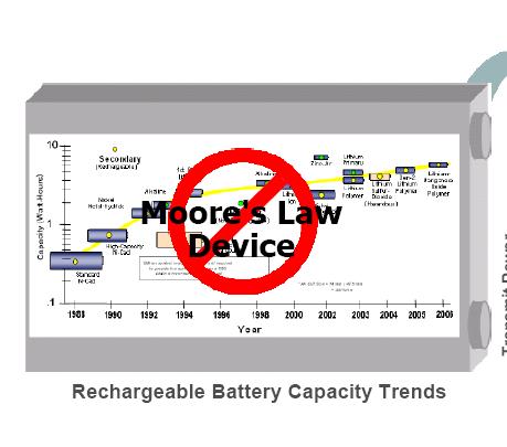
21 Energy constrains 21
22 Wireless Networks Are extremely complex Have been used for many different purposes Have their own distinct characteristics due to radio propagation characteristics & mobility wireless channels can be highly asymmetric & time varying 22
23 Wireless Networks & Mobile Computing Lecture on Physical Layer 23
24 From Signals to Packets Analog Signal Digital Signal Bit Stream Packets Header/Body Header/Body Header/Body Packet Transmission Sender Receiver Note: there is no co-relation between the above figures. Each one is independent from the others.
25 Internet Network Layers -(TCP/IP stack) Layer 5 Layer 4 Layer 3 Layer 2 Layer 1 application transport network link physical Transmission of sequence of bits & signals across a link Signal: superimposition of electromagnetic waves

26 (meters) = 300 / freq in MHz Spectrum
27 Transmitter & Radio Channel Transmitter Receiver Transmitter Fading + Receiver Noise 27
28 Electromagnetic Waveforms Two important properties Propagate They travel in the space from the sender to a receiver Transfer energy This energy can be used for data transmission 28
29 Antenna (1/2) Made of conducting material Radio waves hitting an antenna cause electrons to flow in the conductor and create current Likewise, applying a current to an antenna creates an electric field around the antenna As the current of the antenna changes, so does the electric field A changing electric field causes a magnetic field, and the wave is off 29
30 Antenna (2/2) Antenna gain the extent to which it enhances the signal in its preferred direction Isotropic antenna radiates power with unit gain uniformly in all directions Measured in dbi: decibels relative to an isotropic radiator 30
31 Conversion of a stream of bits into signal Adds redundancy Conversion Bits mapped of a stream to of signal bits into (analog signal signal waveform) protects from interference noise Interference Fading 31
32 Electromagnetic-Field Equations In the far field, the electric & magnetic fields at any given location are: perpendicular to both each other & to the direction of propagation from the antenna proportional to each other (so it is sufficient to know only one of them) In response to a transmitted sinusoid cos(2πft), the electric far field at time t can be expressed as: E (f, t (r,θ,ψ)) = a s (θ, ψ, f) * cos (2πf(t-r/c) ) / r Point u (r,θ,ψ) in which the electric field is being measured Distance r from the transmit antenna to point u Radiation pattern of the sending frequency f & direction (θ,ψ) 32
33 Wavelength of Electromagnetic Radiation Frequency f Wavelength = c/f where c is the speed of light c=3x10 8 m/s Example: cellular communication around 0.9GHz, 1.9GHz, and 5.8GHz wavelength is a fraction of a meter To calculate the electromagnetic field equations at a receiver: the locations of receiver, transmitter & obstructions need to be known with sub-meter accuracy 33
34 Signals Amplitude (A) Maximum value, peak deviation of the function Frequency (f ): Rate, number of oscillations in a unit time interval, in cycles/sec ή Hertz (Hz) Phase(φ) Specifies the relative position in its cycle the oscillation begins general wave formula s(t ) = A sin(2πft + φ) Any waveform can be presented as a collection of periodic analog signals (cosines) with different amplitudes, phases, and frequencies

35 Wave aggregation by superposition When multiple waves converge on a point, the total wave is simply the sum of any component waves 35
36 Wireless channels Operate through electromagnetic radiation from the transmitter to the receiver In principle, one could solve the electromagnetic field equations, in conjunction with the transmitted signal to find the electromagnetic field impinging on the receiver antenna This would have to be done taking into account the obstructions caused by ground, buildings, vehicles, etc in the vicinity of this electromagnetic wave 36
37 Fundamentals Impairments Radio Propagation Wireless channel model Digital modulation and detection techniques Error control techniques 37
38 Types of Impairments Noise: thermal (electronics at the receiver), human Radio frequency signal path loss Fading at low rates Inter-Symbol interference (ISI) Shadow fading Co-channel interference Adjacent channel interference 38
39
40 Multipath fading Multipath: the propagation phenomenon that results in radio signals reaching the receiving antenna by two or more paths
41 Main issues in wireless communications Fading: time variation of signal strength due to: Small-scale effect of multipath fading Larger-scale effects, such as Path loss via distance attenuation Shadowing via obstacles Interference Unlike the wired world, where transmitter-receiver pair can often be though of as an isolated point-to-point link, wireless users communicate over the air & there is significant interference between them 41
42 Types of fading Large-scale fading, due to path loss of signal as function of distance & shadowing by large objects (hills, buildings) This occurs as wireless devices move through a distance of the order of cell size and is typically frequency independent large transmitter-receiver distances Small-scale fading, due to constructive & destructive interference of multiple signal paths between transmitter & receiver This occurs at the spatial scale of the order of the carrier wavelength and is frequency dependent rapid fluctuations of the received signal strength over very short travel distances or short time durations (order of seconds) 42
43 Channel quality varies over multiple time-scales Signal strength changes over time and space Stochastic processes to model signal strength Challenging task Environments with mobility and obstactles Large-scale fading ( slow scale): due to shadowing, path-loss Small-scale fading: due to multipath effects averaging in this period 43
44
45 Different types of fading Wall Scattering Transmitter Cabinet Receiver Diffraction (Shadow Fading) Reflection Wall 45

46 Example of multi-path 1: free space loss likely to give an accurate estimate of path 2: strong line-of-sight but ground reflections can significantly influence path significant diffraction losses caused by trees cutting into the direct line of 4: simple diffraction model for path 5: multiple diffraction, loss prediction fairly difficult & unreliable 46
47 Shadow Fading Obstacles and their absorption behavior Shadowing differs from multi-path fading Duration of shadow fade lasts for multiple seconds or minutes a much slower time-scale compared to multi-path fading 47
48 Reflection Wave impinges upon a large object when compared to the wavelength of the propagating wave Reflections occur from the surface of The earth Buildings Walls 48
49 Scattering Another type of reflection Can occur in the atmosphere or in reflections from very rough objects Very large number of individual paths Received waveform is better modeled as an integral over paths with infinitesimally small differences in their lengths rather than as a sum 49
50 Multi-path Delay Spread Time between the arrival of the first wavefront & last multi-path echo, counting only the paths with significant energy Longer delay spreads require more conservative coding b networks can handle delay spreads of < 500 ns Performance is much better when the delay spread is low When delay spread is large cards may reduce transmission rate 50
51 Inter-Symbol Interference (ISI) Waves that take different paths from the transmitter to the receiver: travel different distances be delayed with respect to each other Waves are combined by superposition but the effect is that the total waveform is garbled Overflowing symbols 51
52 Distortion Caused by the propagation speed & fading Depends on the frequency (varies in different frequencies) Frequency Selective Fading: the channel gain varies for different frequencies of the transmitted signal
53 Frequency Selective Fading The frequency response of a fading channel is not constant within the available bandwidth The channel gain may vary for different frequencies of the transmitted signal Square distortion x-axis: frequency H 2 (f): the square of channel frequency response
54 Channel Impulse Response If the channel is stationary over a small time interval the channel impulse response may be written as: h( t) N 1 i 0 α i & θ i : the amplitude & phase of the i th multipath copy t i : time of arrival of the i th copy a i exp( j ) ( t t ) i i Channel frequency response H(f): Fourier transform of h(t) H( f ) h( t) e j2 ft dt
55 Power Spectral Density of the Received Signal The power spectral density of the received signal (S r ) is equal to the power spectral density of the transmitted signal (S t ) multiplied by the square of the amplitude of the channel frequency response 2 S r ( ) S t

56 Propagation Models One of the most difficult part of the radio channel design Done in statistical fashion based on measurements made specifically for an intended communication system or spectrum allocation Predicting the average signal strength at a given distance from the transmitter 56
57 Some Real-life Measurements 57
58 Signal Power Decay with Distance A signal traveling from one node to another experiences fast (multipath) fading, shadowing & path loss Ideally, averaging RSS over sufficiently long time interval excludes the effects of multipath fading & shadowing general path-loss model: P(d) = P 0 10n log 10 (d/d o ) n: path loss exponent P(d): the average received power in db at distance d P 0 is the received power in db at a short distance d 0 58
59 Free-space Propagation Model Assumes a single direct path between the base station and the mobile Predicts received signal strength when the transmitter & receiver have a clear, unobstructed line-of-sight path between them Typically used in an open wide environment Examples: satellite, microwave line-of-sight radio links 60
60 Free-space Propagation Model Derived from first principles: power flux density computation Any radiating structure produces electric & magnetic fields: its current flows through such antenna and launches electric and magnetic fields The electrostatic and inductive fields decay much faster with distance than the radiation field At regions far way from the transmitter: the electrostatic & inductive fields become negligible and only the radiated field components need be considered 61
61 Free-space Propagation Model P r (d)=p t G t G r 2 /[(4 ) 2 d 2 L] P t,p r : transmitter/receiver power G t, G r : transmitter/receiver antenna gain G = 4 A e / 2 L: system loss factor (L=1 no loss) A e: related to the physical size of the antenna : wavelength in meters, f carrier frequency, c :speed of light = c/f 62
62 Two-ray ground reflection model T (transmitter) P r (d) = P t G t G r h r2 h t2 /d 4 h t R (receiver) h r d 63
63 Two-ray Ground Reflection Model Considers both the direct path & a ground reflected propagation path between transmitter and receiver Reasonably accurate for predicting the large-scale signal strength 1. over distances of several km for mobile radio systems that use tall tower (heights which exceed 40m) 2. for line-of-sight micro-cell channels in urban environment 64
64 Multiple Reflectors Use ray tracing Modeling the received waveform as the sum of the responses from the different paths rather than just two paths Finding the magnitudes and phases of these responses is not a simple task 65
65 Multi-path Delay Spread Difference in propagation time between the longest and shortest path, counting only the paths with significant energy 66
66 Modeling Electromagnetic Field In the cellular bands the wavelength is a fraction of meter To calculate the electromagnetic field at the receiver, the locations of the receiver and the obstructions would have to be known with sub-meter accuracies. 67
67 Free space Fixed transmit & Receive Antennas In the far field, the electric field and magnetic field at any given location are perpendicular both to each other & to the direction of propagation from the antenna proportional to each other 68
68 Free-space fixed transmit & receive antennas In response to a transmitted sinusoid cos(2 ft), the electric far field at time t can be expressed as: E( f, t,( d,, )) = a s (,, f) cos(2 f (t-d/c)) / d vertical & horizontal angles from the antenna to u Radiation pattern of sending antenna at frequency f (incl. antenna loss) point u in which the electric field is being measured d distance from the transmit to receive antennas 69
69 hysical-layer Model Criterion for Successful Transmission subset of nodes simultaneously transmitting at some time instance over a certain sub-channel. Power level chosen by node X k ambient noise power level minimum Signal-to-interference ratio Signal power decays with distance 70
70 Signal-to-noise ratio (SNR) The ratio between the magnitude of background noise and the magnitude of un-distorted signal (meaningful information) on a channel Higher SNR is better (i.e., cleaner) It determines how much information each symbol can represent 71
71 Capacity of a channel How many bits of information can be transmitted without error per sec over a channel with bandwidth B average signal power P the signal is exposed to an additive, white (uncorrelated) noise of power N with Gaussian probability distribution provides the fundamental limit of communication achievable by any scheme 72

 Norbert Wiener")
72 Limits of wireless channel Shannon [1948] defined the capacity limit for communication channels Shannon ( ) Norbert Wiener ( ) 73
73 Shannon s limit For a channel without shadowing, fading, or ISI, the maximum possible data rate on a given channel of bandwidth B is R=Blog 2 (1+SNR) bps, where SNR is the received signal to noise ratio Shannon s is a theoretical limit that cannot be achieved in practice but design techniques improve data rates to approach this bound 74
74 Digital Radio Communications Data In Baseband Modulation Carrier Radio Channel Transmitter Conversion of a stream of bits into signal Carrier Bit &Frame Sync Detection Decision Data Out Receiver Conversion of the signal to a stream of bits 75
75 Conversion of a stream of bits into signal Adds redundancy Conversion Bits mapped of a stream to of signal bits into (analog signal signal waveform) protects from interference noise Interference Fading 76
76 Adds redundancy to protect the digital information from noise and interference Bits mapped to signal (analog signal waveform) e.g., GFSK e.g., TDMA, CDMA 77
77 Channel Coding Protects the digital information from noise & interference & reduces the number of bit errors Accomplished by selectively introducing redundant bits into the transmitted information stream These additional bits allow detection & correction of bit errors in the received data stream 78
78 Encoding Use two discrete signals, high and low, to encode 0 and 1 Transmission is synchronous, i.e., a clock is used to sample the signal In general, the duration of one bit is equal to one or two clock ticks Receiver s clock must be synchronized with the sender s clock Encoding can be done one bit at a time or in blocks of, e.g., 4 or 8 bits 79
79 Why Do We Need Encoding? Meet certain electrical constraints Receiver needs enough transitions to keep track of the transmit clock Avoid receiver saturation Create control symbols, besides regular data symbol e.g. start or end of frame Error detection or error corrections Some codes are illegal so receiver can detect certain classes of errors Minor errors can be corrected by having multiple adjacent signals mapped to the same data symbol Encoding can be very complex, e.g. wireless 80
80 Digital Modulation The process of taking information from a message source (baseband) in a suitable manner for transmission & translating the baseband signal onto a radio carrier at frequencies that are very high compared to the baseband frequency 81
81 Why not modulate the baseband For effective signal radiation the length of the antenna must be proportional to the transmitted wave length For example, voice range Hz At 3kHz at 3kbps would imply an antenna of 100Km! By modulating the baseband on a 3GHz carrier the antenna would be 10cm To ensure the orderly coexistence of multiple signals in a given spectral band To help reduce interference among users For regulatory reasons 82
82 Demodulation The process of extracting the baseband from the carrier so that it may be processed and interpreted by the receiver (e.g., symbols detected and extracted) 83
83 Digital Modulation Approaches Frequency shift Keying (FSK) Use of different carrier frequencies to encode the various symbols Phase shift Keying (PSK) Use of a single carrier frequency The various symbols are encoded by the phase Quadrature Amplitude Modulation(QAM) Both phase & amplitude are used for the encoding of various symbols
84 FSK modulation An alphabet of M symbols is used (M = 2 K for some K N) Each symbols corresponds to a combination of K bits The i-th symbol is mapped to carrier frequency F i = (n+i)/2t T: symbol duration n: arbitrary integer (for selecting an appropriate frequency band) In order to transmit the i-th symbol, the following signal is used Si ( t) 2E cos(2 Ft i ), 0 t T 0 elseware T
85 Example BFSK F 0 F 1 n 1 2T n 2 2T Bit 0 corresponds to: Bit 1 corresponds to: 2E T 2E T cos(2 F 0 t) cos(2 F 1 t)
86 FSK demodulation Consider a vector space with base vectors 2 bi cos(2 Ft i ), i 1,2,..., M The transmitted & the received signals correspond to different points on this vector space This is due to noise & the channel gain The largest coordinate of the received signal corresponds to the transmitted symbol with high probability
87 BFSK demodulation When the received signal is bellow the dashed line, it is assumed that bit 0 is transmitted Otherwise, it is assumed that bit 1 is transmitted Due to path loss, there is an energy attenuation Resulting to a received signal residing in the circle instead of on the periphery However, due to constructive phenomena, in other situations, the received signal may reside outside of the circle
88 PSK modulation The alphabet contains M = 2 K different symbols To transmit the i-th symbol, the following signal is transmitted Si ( t) 2E T cos(2 F t ), elseware 0 t Signals S i (t) are linearly dependent 0 c i they can be represented by linear combination of the vectors: T 2 b1 cos(2 F ct) 2 b2 sin(2 F ct)
89 Example BPSK / 2 1 / 2 Bit 0 corresponds to : 2E T cos(2 F t / c 2) Bit 1 corresponds to: 2E T cos(2 F t / c 2)
90 QPSK If the received signal lies in the 1 st quadrant, assume that the 00 is transmitted In the 2 nd quadrant, assume that 01 is transmitted, etc
91 8PSK If the received signal lies in the 1 st area, it is assumed that the 000 is transmitted If it lies in the 2 nd area, it is assumed that 001 is transmitted etc
92 QAM modulation This modulation scheme is an expansion of PSK A single carrier frequency is used (F c ) The transmitted & received signals are represented as linear combinations of: b 2 2 cos(2 F c ) b2 sin(2 F ct) 1 t The difference is that not only the phase but also the amplitude of the carrier signal may vary
93 Example: 16QAM The constellation point, closer to the received signal, is assumed to correspond to the transmitted bit combination
94 PDF of the received signal Probability that the received signal would lie at a particular point: 2D Gaussian The probability space of the PDF is the vector space of the signals The peak of the distribution corresponds to the transmitted signal
95 BER calculation transmitted symbol To calculate BER: compute the integral of the signal PDF in red zone For 8PSK: red zone is larger and yields a higher BER The additional red zones in 8PSK have large probability mass ~ BER is significantly higher in 8PSK than in QPSK

96 BER calculation transmitted symbol The peak of the 2D Gaussian corresponds to The position of the transmitted signal the contribution to the BER of these regions is larger
97 Gaussian frequency shift keying (GFSK) Encodes data as a series of frequency changes in a carrier Noise usually changes the amplitude of a signal Modulation that ignores amplitude (e.g., broadcast FM) Relatively immune to noise Gaussian refers to the shape of radio pulses 98
98 2GFSK Two different frequencies To transmit 1 The carrier frequency is increased by a certain deviation To transmit 0 The carrier frequency is decreased by the same deviation 99
99 2GFSK of letter M ( ) When 1 is transmitted, frequency rises to the center frequency plus an offset When 0 is transmitted, frequency drops by the same offset The horizontal axis represents time and is divided into symbol periods Around the middle of each period, the receiver measures the frequency of the transmission and translates that frequency into a symbol 100
100 4GFSK Extending GFSK-based methods to higher bit rates 101
101 2GFSK vs. 4GFSK Distinguishing between two levels is fairly easy Four is harder: Each doubling of the bit rate requires that twice as many levels be present the RF components distinguish between ever smaller frequency changes This issue practically limits the FH PHY to 2 Mbps 102
102 Differential Phase Shift Keying (DPSK) Basis of DSSS Absolute phase of waveform is not relevant Only changes in the phase encode data Two carrier waves Shifted by a half cycle relative to each other Reference wave: encodes 0 Half-cycle (180 o ) shifted wave: encodes 1 103
103 Differential quadrature phase shift keying (DQPSK) Symbol Phase Shift o o o 104
104 Multiple Access Techniques Frequency Division Multiple Access (FDMA) Each device is allocated a fixed frequency Multiple devices share the available radio spectrum by using different frequencies Code Division Multiple Access (CDMA) Direct Sequence Spread Spectrum (DSSS) Frequency Hopping (FH) Orthogonal Frequency Division Multiplexing (OFDM) 105
105 Spread spectrum Traditional radio communications focus on cramming as much signal as possible into as narrow a band as possible Spread spectrum use mathematical functions to diffuse signal power over large range of frequencies Spreading the transmission over wide band makes transmission look like noise to a traditional narrowband receiver 106
106 Spread Spectrum Technology Spread radio signal over a wide frequency range several magnitudes higher than minimum requirement Use of noise-like carrier waves and bandwidths much wider than that required for simple point-to-point communication at the same data rate Electromagnetic energy generated in a particular bandwidth is deliberately spread in the frequency domain, resulting in a signal with a wider bandwidth Used for a variety of reasons establishment of secure communications increasing resistance to natural interference and jamming prevent detection Two main techniques: Direct sequence (DS) Frequency hopping (FH) 107
107 Frequency division multiple access First generation mobile phones used it for radio channel allocation Each user was given an exclusive channel Guard bands were used to ensure that spectral leakage from one user did not cause problems for users of adjacent channels Band 1 Guard Band 2 Guard Band 3 band band Frequency 108
108 Problems with FDMA? Wasting transmission capacity with unused guard bands 109
109 Code division multiple access (CDMA) CDMA assigns a different code to each node Codes orthogonal to each other (i.e inner-product = 0) Each node uses its unique code to encode the data bits it sends Nodes can transmit simultaneously Multiple nodes per channel Their respective receivers Correctly receive a sender s encoded data bits Assuming the receiver knows the sender s code in spite of interfering transmissions by other nodes 110
110 CDMA Example Sender Data bits d 1 =-1 d 0 =1 Z i,m =d i *c m Spread code Time slot 1 Time slot Channel output
111 CDMA Example (cont d) When no interfering senders, receiver would Receive the encoded bits Recover the original data bit, d i, by computing d i = S Z i,m *c m Interfering transmitted bit signals are additive M m=1 112
112 CDMA Philosophy Interference seen by any user is made as similar to white Gaussian noise as possible Power of that interference is kept to a minimum level and as consistent as possible The above are achieved by the following Tight power control among users within the same cell Making the received signal of every user as random looking as possible via modulating the coded bits onto a long pseudo-noise sequence Averaging the interference of many users in nearby cells. This averaging makes the aggregate interference to look as Gaussian reduces the randomness of the interference level due to varying locations of the interference 113

113 Inverts the spreading process Flatten the amplitude across a relatively wide band The receiver s correlation function effectively ignores narrowband 114 noise
114 Orthogonal Frequency Division Multiplexing Related to the Frequency Division Multiplexing (FDM) Distributes the data over a large number of carriers Spaced apart at precise frequencies Encodes portion of the signal across each sub-channel in parallel This spacing provides the "orthogonality" Preventing demodulators from seeing other frequencies Provides High spectral efficiency Resiliency to RF interference Lower multi-path distortion 115
115 OFDM the peak of each of the subcarriers the other 2 subcarriers have 0 amplitude Orthogonality is best seen in the frequency domain, looking at a spectral breakdown of a signal The frequencies of the subcarriers are selected so that at each subcarrier frequency, all other subcarriers do not contribute to the overall waveform The signal has been divided into its three subcarriers The peak of each subcarrier, shown by the heavy dot at the top, encodes data The subcarrier set carefully designed to be orthogonal 116

116 FDM vs. OFDM 117

117 Example of OFDM Transmitter & Receiver 118

118 Example of OFDM 119
119 OFDM Modulation The bit stream is divided into N parallel subflows The symbols of each subflow are modulated using MPSK or MQAM Resulting complex numbers are fed to a module that performs FFT -1 Finally the signal is converted from digital to analog, brought to the RF frequencies, and then fed to the antenna of the transmitter
120 OFDM Demodulation At the receiver the inverse procedure is followed 1. The signal is brought down to baseband & is converted from analog to digital 2. FFT is performed produces the transmitted symbols
121 Frequency Selective Fading The frequency response of a fading channel is not constant within the available bandwidth The channel gain may vary for different frequencies of the transmitted signal Square distortion H 2 (f): the square of channel frequency response
 Square Multiple transmitted signals (one symbol per frequency bin) Note: larger symbol duration per bin (compared to spread spectrum schemes) There is (a different)")
122 Use OFDM To reduce the effect of frequency selective fading The total available bandwidth is divided into N frequency bins The number N is selected such that the channel frequency response is almost constant at each bin (Flat fading) Square Multiple transmitted signals (one symbol per frequency bin) Note: larger symbol duration per bin (compared to spread spectrum schemes) There is (a different) attenuation at each bin but the spectral characteristics of the signal remain the same
123 CDMA vs. OFDM OFDM encodes single transmission into multiple subcarriers CDMA puts multiple transmissions into single carrier 124
124 Frequency Hopping Timing the hops accurately is the key Transmitter and receiver in synch Each frequency is used for small amount of time (dwell time) Orthogonal hoping sequences Beacons include timestamp and hop pattern number Divides the ISM band into a series of 1-MHz channels No sophisticated signal processing required To extract bit stream from the radio signal 125
125 Frequency Hopping Frequency slot Timing the hops accurately is the challenge User A User B Time slot 126
126 Wireless network interfaces Measure the energy level in a band Energy detection is cheap, fast, & requires no knowledge of the characteristics of the signal However, choosing energy thresholds is not robust across a wide range of SNRs Though more sophisticated mechanisms, such as matched filter detection, are more accurate they require knowledge of the transmitted signal (e.g., modulation, packet format, pilots, bandwidth), and thus work only for known technologies 127

127 Network Layers -(TCP/IP stack) IEEE application transport network link physical How neighboring devices access the link In IEEE802.11, devices may compete for the broadcast channel Transmission of sequence of bits & signals across a link
128 IEEE Family b: Direct Sequence Spread Spectrum (DSSS) or Frequency Hopping (FH), operates at 2.4GHz, 11Mbps bitrate a: between 5GHz and 6GHz uses orthogonal frequencydivision multiplexing, up to 54Mbps bitrate g: operates at 2.4GHz up to 54Mbps bitrate All have the same architecture & use the same MAC protocol
129 Coverage of a Cell The largest distance between the base-station & a mobile at which communication can reliably take place Cell coverage is constrained by the fast decay of power with distance To alleviate the inter-cell interference, neighboring cells use different parts of the frequency spectrum The rapid signal attenuation with distance is also helpful; it reduces the interference between adjacent cells Spatial reuse Frequency is reused at cells that are far enough 130
130 Hidden Node Problem Node 1 Node 2 Node 3 From the perspective of node 1 Node 3 is hidden If node 1 and node 3 communicate simultaneously Node 2 will be unable to make sense of anything Node 1 and node 3 would not have any indication of error The collision was local to node2 131
131 Carrier-Sensing Functions Physical carrier-sensing Expensive to build hardware for RF-based media Transceivers can transmit and receive simultaneously Only if they incorporate expensive electronics Hidden nodes problem Fading problem Virtual carrier-sensing Undetectable collisions Collision avoidance: Stations delay transmission until the medium becomes idle Reduce the probability of collisions 132
132 Next. We will talk more about IEEE MAC and then about performance issues of wireless networks 133
Outline / Wireless Networks and Applications Lecture 3: Physical Layer Signals, Modulation, Multiplexing. Cartoon View 1 A Wave of Energy
 Outline 18-452/18-750 Wireless Networks and Applications Lecture 3: Physical Layer Signals, Modulation, Multiplexing Peter Steenkiste Carnegie Mellon University Spring Semester 2017 http://www.cs.cmu.edu/~prs/wirelesss17/
Chapter 7. Multiple Division Techniques
 Chapter 7 Multiple Division Techniques 1 Outline Frequency Division Multiple Access (FDMA) Division Multiple Access (TDMA) Code Division Multiple Access (CDMA) Comparison of FDMA, TDMA, and CDMA Walsh
Simple Algorithm in (older) Selection Diversity. Receiver Diversity Can we Do Better? Receiver Diversity Optimization.
 Selection Diversity. Receiver Diversity Can we Do Better? Receiver Diversity Optimization.") 18-452/18-750 Wireless Networks and Applications Lecture 6: Physical Layer Diversity and Coding Peter Steenkiste Carnegie Mellon University Spring Semester 2017 http://www.cs.cmu.edu/~prs/wirelesss17/
18-452/18-750 Wireless Networks and Applications Lecture 6: Physical Layer Diversity and Coding Peter Steenkiste Carnegie Mellon University Spring Semester 2017 http://www.cs.cmu.edu/~prs/wirelesss17/
Announcements : Wireless Networks Lecture 3: Physical Layer. Bird s Eye View. Outline. Page 1
 Announcements 18-759: Wireless Networks Lecture 3: Physical Layer Please start to form project teams» Updated project handout is available on the web site Also start to form teams for surveys» Send mail
OFDMA and MIMO Notes
 OFDMA and MIMO Notes EE 442 Spring Semester Lecture 14 Orthogonal Frequency Division Multiplexing (OFDM) is a digital multi-carrier modulation technique extending the concept of single subcarrier modulation
Mobile & Wireless Networking. Lecture 2: Wireless Transmission (2/2)
") 192620010 Mobile & Wireless Networking Lecture 2: Wireless Transmission (2/2) [Schiller, Section 2.6 & 2.7] [Reader Part 1: OFDM: An architecture for the fourth generation] Geert Heijenk Outline of Lecture
192620010 Mobile & Wireless Networking Lecture 2: Wireless Transmission (2/2) [Schiller, Section 2.6 & 2.7] [Reader Part 1: OFDM: An architecture for the fourth generation] Geert Heijenk Outline of Lecture
ECE 476/ECE 501C/CS Wireless Communication Systems Winter Lecture 6: Fading
 ECE 476/ECE 501C/CS 513 - Wireless Communication Systems Winter 2005 Lecture 6: Fading Last lecture: Large scale propagation properties of wireless systems - slowly varying properties that depend primarily
Chapter 2: Wireless Transmission. Mobile Communications. Spread spectrum. Multiplexing. Modulation. Frequencies. Antenna. Signals
 Mobile Communications Chapter 2: Wireless Transmission Frequencies Multiplexing Signals Spread spectrum Antenna Modulation Signal propagation Cellular systems Prof. Dr.-Ing. Jochen Schiller, http://www.jochenschiller.de/
Outline / Wireless Networks and Applications Lecture 5: Physical Layer Signal Propagation and Modulation
 Outline 18-452/18-750 Wireless Networks and Applications Lecture 5: Physical Layer Signal Propagation and Modulation Peter Steenkiste Carnegie Mellon University Spring Semester 2017 http://www.cs.cmu.edu/~prs/wirelesss17/
ECE 476/ECE 501C/CS Wireless Communication Systems Winter Lecture 6: Fading
 ECE 476/ECE 501C/CS 513 - Wireless Communication Systems Winter 2004 Lecture 6: Fading Last lecture: Large scale propagation properties of wireless systems - slowly varying properties that depend primarily
Point-to-Point Communications
 Point-to-Point Communications Key Aspects of Communication Voice Mail Tones Alphabet Signals Air Paper Media Language English/Hindi English/Hindi Outline of Point-to-Point Communication 1. Signals basic
Chapter 7 Multiple Division Techniques for Traffic Channels
 Introduction to Wireless & Mobile Systems Chapter 7 Multiple Division Techniques for Traffic Channels Outline Introduction Concepts and Models for Multiple Divisions Frequency Division Multiple Access
Lecture 9: Spread Spectrum Modulation Techniques
 Lecture 9: Spread Spectrum Modulation Techniques Spread spectrum (SS) modulation techniques employ a transmission bandwidth which is several orders of magnitude greater than the minimum required bandwidth
Project = An Adventure : Wireless Networks. Lecture 4: More Physical Layer. What is an Antenna? Outline. Page 1
 Project = An Adventure 18-759: Wireless Networks Checkpoint 2 Checkpoint 1 Lecture 4: More Physical Layer You are here Done! Peter Steenkiste Departments of Computer Science and Electrical and Computer
Wireless Communication: Concepts, Techniques, and Models. Hongwei Zhang
 Wireless Communication: Concepts, Techniques, and Models Hongwei Zhang http://www.cs.wayne.edu/~hzhang Outline Digital communication over radio channels Channel capacity MIMO: diversity and parallel channels
ECE 476/ECE 501C/CS Wireless Communication Systems Winter Lecture 6: Fading
 ECE 476/ECE 501C/CS 513 - Wireless Communication Systems Winter 2003 Lecture 6: Fading Last lecture: Large scale propagation properties of wireless systems - slowly varying properties that depend primarily
Lecture 3: Wireless Physical Layer: Modulation Techniques. Mythili Vutukuru CS 653 Spring 2014 Jan 13, Monday
 Lecture 3: Wireless Physical Layer: Modulation Techniques Mythili Vutukuru CS 653 Spring 2014 Jan 13, Monday Modulation We saw a simple example of amplitude modulation in the last lecture Modulation how
Wireless Transmission & Media Access
 Wireless Transmission & Media Access Signals and Signal Propagation Multiplexing Modulation Media Access 1 Significant parts of slides are based on original material by Prof. Dr.-Ing. Jochen Schiller,
S.D.M COLLEGE OF ENGINEERING AND TECHNOLOGY
 VISHVESHWARAIAH TECHNOLOGICAL UNIVERSITY S.D.M COLLEGE OF ENGINEERING AND TECHNOLOGY A seminar report on Orthogonal Frequency Division Multiplexing (OFDM) Submitted by Sandeep Katakol 2SD06CS085 8th semester
Announcement : Wireless Networks Lecture 3: Physical Layer. A Reminder about Prerequisites. Outline. Page 1
 Announcement 18-759: Wireless Networks Lecture 3: Physical Layer Peter Steenkiste Departments of Computer Science and Electrical and Computer Engineering Spring Semester 2010 http://www.cs.cmu.edu/~prs/wirelesss10/
Multiple Access Schemes
 Multiple Access Schemes Dr Yousef Dama Faculty of Engineering and Information Technology An-Najah National University 2016-2017 Why Multiple access schemes Multiple access schemes are used to allow many
CHAPTER 2 WIRELESS CHANNEL
 CHAPTER 2 WIRELESS CHANNEL 2.1 INTRODUCTION In mobile radio channel there is certain fundamental limitation on the performance of wireless communication system. There are many obstructions between transmitter
Chapter 2 Channel Equalization
 Chapter 2 Channel Equalization 2.1 Introduction In wireless communication systems signal experiences distortion due to fading [17]. As signal propagates, it follows multiple paths between transmitter and
Wireless Communication Fundamentals Feb. 8, 2005
 Wireless Communication Fundamentals Feb. 8, 005 Dr. Chengzhi Li 1 Suggested Reading Chapter Wireless Communications by T. S. Rappaport, 001 (version ) Rayleigh Fading Channels in Mobile Digital Communication
Part 3. Multiple Access Methods. p. 1 ELEC6040 Mobile Radio Communications, Dept. of E.E.E., HKU
 Part 3. Multiple Access Methods p. 1 ELEC6040 Mobile Radio Communications, Dept. of E.E.E., HKU Review of Multiple Access Methods Aim of multiple access To simultaneously support communications between
UNIT- 7. Frequencies above 30Mhz tend to travel in straight lines they are limited in their propagation by the curvature of the earth.
 UNIT- 7 Radio wave propagation and propagation models EM waves below 2Mhz tend to travel as ground waves, These wave tend to follow the curvature of the earth and lose strength rapidly as they travel away
The Radio Channel. COS 463: Wireless Networks Lecture 14 Kyle Jamieson. [Parts adapted from I. Darwazeh, A. Goldsmith, T. Rappaport, P.
 The Radio Channel COS 463: Wireless Networks Lecture 14 Kyle Jamieson [Parts adapted from I. Darwazeh, A. Goldsmith, T. Rappaport, P. Steenkiste] Motivation The radio channel is what limits most radio
Digital Modulation Schemes
 Digital Modulation Schemes 1. In binary data transmission DPSK is preferred to PSK because (a) a coherent carrier is not required to be generated at the receiver (b) for a given energy per bit, the probability
CSCD 433 Network Programming Fall Lecture 5 Physical Layer Continued
 CSCD 433 Network Programming Fall 2016 Lecture 5 Physical Layer Continued 1 Topics Definitions Analog Transmission of Digital Data Digital Transmission of Analog Data Multiplexing 2 Different Types of
E-716-A Mobile Communications Systems. Lecture #2 Basic Concepts of Wireless Transmission (p1) Instructor: Dr. Ahmad El-Banna
 Instructor: Dr. Ahmad El-Banna") October 2014 Ahmad El-Banna Integrated Technical Education Cluster At AlAmeeria E-716-A Mobile Communications Systems Lecture #2 Basic Concepts of Wireless Transmission (p1) Instructor: Dr. Ahmad El-Banna
October 2014 Ahmad El-Banna Integrated Technical Education Cluster At AlAmeeria E-716-A Mobile Communications Systems Lecture #2 Basic Concepts of Wireless Transmission (p1) Instructor: Dr. Ahmad El-Banna
Lecture 13. Introduction to OFDM
 Lecture 13 Introduction to OFDM Ref: About-OFDM.pdf Orthogonal frequency division multiplexing (OFDM) is well-known to be effective against multipath distortion. It is a multicarrier communication scheme,
Vehicle Networks. Wireless communication basics. Univ.-Prof. Dr. Thomas Strang, Dipl.-Inform. Matthias Röckl
 Vehicle Networks Wireless communication basics Univ.-Prof. Dr. Thomas Strang, Dipl.-Inform. Matthias Röckl Outline Wireless Signal Propagation Electro-magnetic waves Signal impairments Attenuation Distortion
Wireless Networked Systems. Lec #1b: PHY Basics
 Wireless Networked Systems CS 795/895 - Spring 2013 Lec #1b: PHY Basics Tamer Nadeem Dept. of Computer Science Wireless Communication Page 2 Spring 2013 CS 795/895 - Wireless Networked Systems Radio Signal
CS263: Wireless Communications and Sensor Networks
 CS263: Wireless Communications and Sensor Networks Matt Welsh Lecture 3: Antennas, Propagation, and Spread Spectrum September 30, 2004 2004 Matt Welsh Harvard University 1 Today's Lecture Antennas and
Antennas and Propagation
 CMPE 477 Wireless and Mobile Networks Lecture 3: Antennas and Propagation Antennas Propagation Modes Line of Sight Transmission Fading in the Mobile Environment Introduction An antenna is an electrical
MODULATION AND MULTIPLE ACCESS TECHNIQUES
 1 MODULATION AND MULTIPLE ACCESS TECHNIQUES Networks and Communication Department Dr. Marwah Ahmed Outlines 2 Introduction Digital Transmission Digital Modulation Digital Transmission of Analog Signal
UTILIZATION OF AN IEEE 1588 TIMING REFERENCE SOURCE IN THE inet RF TRANSCEIVER
 UTILIZATION OF AN IEEE 1588 TIMING REFERENCE SOURCE IN THE inet RF TRANSCEIVER Dr. Cheng Lu, Chief Communications System Engineer John Roach, Vice President, Network Products Division Dr. George Sasvari,
ISHIK UNIVERSITY Faculty of Science Department of Information Technology Fall Course Name: Wireless Networks
 ISHIK UNIVERSITY Faculty of Science Department of Information Technology 2017-2018 Fall Course Name: Wireless Networks Agenda Lecture 4 Multiple Access Techniques: FDMA, TDMA, SDMA and CDMA 1. Frequency
CALIFORNIA STATE UNIVERSITY, NORTHRIDGE FADING CHANNEL CHARACTERIZATION AND MODELING
 CALIFORNIA STATE UNIVERSITY, NORTHRIDGE FADING CHANNEL CHARACTERIZATION AND MODELING A graduate project submitted in partial fulfillment of the requirements For the degree of Master of Science in Electrical
Wireless Medium Access Control and CDMA-based Communication Lesson 16 Orthogonal Frequency Division Medium Access (OFDM)
") Wireless Medium Access Control and CDMA-based Communication Lesson 16 Orthogonal Frequency Division Medium Access (OFDM) 1 4G File transfer at 10 Mbps High resolution 1024 1920 pixel hi-vision picture
Wireless Medium Access Control and CDMA-based Communication Lesson 16 Orthogonal Frequency Division Medium Access (OFDM) 1 4G File transfer at 10 Mbps High resolution 1024 1920 pixel hi-vision picture
Page 1. Outline : Wireless Networks Lecture 6: Final Physical Layer. Direct Sequence Spread Spectrum (DSSS) Spread Spectrum
 Spread Spectrum") Outline 18-759 : Wireless Networks Lecture 6: Final Physical Layer Peter Steenkiste Dina Papagiannaki Spring Semester 2009 http://www.cs.cmu.edu/~prs/wireless09/ Peter A. Steenkiste 1 RF introduction Modulation
Outline 18-759 : Wireless Networks Lecture 6: Final Physical Layer Peter Steenkiste Dina Papagiannaki Spring Semester 2009 http://www.cs.cmu.edu/~prs/wireless09/ Peter A. Steenkiste 1 RF introduction Modulation
Fundamentals of Digital Communication
 Fundamentals of Digital Communication Network Infrastructures A.A. 2017/18 Digital communication system Analog Digital Input Signal Analog/ Digital Low Pass Filter Sampler Quantizer Source Encoder Channel
SC - Single carrier systems One carrier carries data stream
 Digital modulation SC - Single carrier systems One carrier carries data stream MC - Multi-carrier systems Many carriers are used for data transmission. Data stream is divided into sub-streams and each
Session2 Antennas and Propagation
 Wireless Communication Presented by Dr. Mahmoud Daneshvar Session2 Antennas and Propagation 1. Introduction Types of Anttenas Free space Propagation 2. Propagation modes 3. Transmission Problems 4. Fading
Antennas and Propagation
 Antennas and Propagation Chapter 5 Introduction An antenna is an electrical conductor or system of conductors Transmission - radiates electromagnetic energy into space Reception - collects electromagnetic
Lecture 5 Transmission
 Lecture 5 Transmission David Andersen Department of Computer Science Carnegie Mellon University 15-441 Networking, Spring 2005 http://www.cs.cmu.edu/~srini/15-441/s05 1 Physical and Datalink Layers: 3
CSCD 433 Network Programming Fall Lecture 5 Physical Layer Continued
 CSCD 433 Network Programming Fall 2016 Lecture 5 Physical Layer Continued 1 Topics Definitions Analog Transmission of Digital Data Digital Transmission of Analog Data Multiplexing 2 Different Types of
Objectives. Presentation Outline. Digital Modulation Revision
 Digital Modulation Revision Professor Richard Harris Objectives To identify the key points from the lecture material presented in the Digital Modulation section of this paper. What is in the examination
CIS 632 / EEC 687 Mobile Computing. Mobile Communications (for Dummies) Chansu Yu. Contents. Modulation Propagation Spread spectrum
 Chansu Yu. Contents. Modulation Propagation Spread spectrum") CIS 632 / EEC 687 Mobile Computing Mobile Communications (for Dummies) Chansu Yu Contents Modulation Propagation Spread spectrum 2 1 Digital Communication 1 0 digital signal t Want to transform to since
CIS 632 / EEC 687 Mobile Computing Mobile Communications (for Dummies) Chansu Yu Contents Modulation Propagation Spread spectrum 2 1 Digital Communication 1 0 digital signal t Want to transform to since
Antennas & Propagation. CSG 250 Fall 2007 Rajmohan Rajaraman
 Antennas & Propagation CSG 250 Fall 2007 Rajmohan Rajaraman Introduction An antenna is an electrical conductor or system of conductors o Transmission - radiates electromagnetic energy into space o Reception
Lecture 3 Concepts for the Data Communications and Computer Interconnection
 Lecture 3 Concepts for the Data Communications and Computer Interconnection Aim: overview of existing methods and techniques Terms used: -Data entities conveying meaning (of information) -Signals data
CSE 561 Bits and Links. David Wetherall
 CSE 561 Bits and Links David Wetherall djw@cs.washington.edu Topic How do we send a message across a wire? The physical/link layers: 1. Different kinds of media 2. Encoding bits 3. Model of a link Application
Structure of the Lecture
 Structure of the Lecture Chapter 2 Technical Basics: Layer 1 Methods for Medium Access: Layer 2 Representation of digital signals on an analogous medium Signal propagation Characteristics of antennas Chapter
Introduction to Wireless Signal Propagation
 Introduction to Wireless Signal Propagation Raj Jain Professor of Computer Science and Engineering Washington University in Saint Louis Saint Louis, MO 63130 Jain@cse.wustl.edu Audio/Video recordings of
Wireless Channel Propagation Model Small-scale Fading
 Wireless Channel Propagation Model Small-scale Fading Basic Questions T x What will happen if the transmitter - changes transmit power? - changes frequency? - operates at higher speed? Transmit power,
Wireless Communications
 2. Physical Layer DIN/CTC/UEM 2018 Periodic Signal Periodic signal: repeats itself in time, that is g(t) = g(t + T ) in which T (given in seconds [s]) is the period of the signal g(t) The number of cycles
QUESTION BANK SUBJECT: DIGITAL COMMUNICATION (15EC61)
") QUESTION BANK SUBJECT: DIGITAL COMMUNICATION (15EC61) Module 1 1. Explain Digital communication system with a neat block diagram. 2. What are the differences between digital and analog communication systems?
QUESTION BANK SUBJECT: DIGITAL COMMUNICATION (15EC61) Module 1 1. Explain Digital communication system with a neat block diagram. 2. What are the differences between digital and analog communication systems?
Receiver Designs for the Radio Channel
 Receiver Designs for the Radio Channel COS 463: Wireless Networks Lecture 15 Kyle Jamieson [Parts adapted from C. Sodini, W. Ozan, J. Tan] Today 1. Delay Spread and Frequency-Selective Fading 2. Time-Domain
EENG473 Mobile Communications Module 3 : Week # (12) Mobile Radio Propagation: Small-Scale Path Loss
 Mobile Radio Propagation: Small-Scale Path Loss") EENG473 Mobile Communications Module 3 : Week # (12) Mobile Radio Propagation: Small-Scale Path Loss Introduction Small-scale fading is used to describe the rapid fluctuation of the amplitude of a radio
EENG473 Mobile Communications Module 3 : Week # (12) Mobile Radio Propagation: Small-Scale Path Loss Introduction Small-scale fading is used to describe the rapid fluctuation of the amplitude of a radio
NOISE, INTERFERENCE, & DATA RATES
 COMP 635: WIRELESS NETWORKS NOISE, INTERFERENCE, & DATA RATES Jasleen Kaur Fall 2015 1 Power Terminology db Power expressed relative to reference level (P 0 ) = 10 log 10 (P signal / P 0 ) J : Can conveniently
CS441 Mobile & Wireless Computing Communication Basics
 Department of Computer Science Southern Illinois University Carbondale CS441 Mobile & Wireless Computing Communication Basics Dr. Kemal Akkaya E-mail: kemal@cs.siu.edu Kemal Akkaya Mobile & Wireless Computing
Multiple Access Techniques
 Multiple Access Techniques EE 442 Spring Semester Lecture 13 Multiple Access is the use of multiplexing techniques to provide communication service to multiple users over a single channel. It allows for
Communication Theory
 Communication Theory Adnan Aziz Abstract We review the basic elements of communications systems, our goal being to motivate our study of filter implementation in VLSI. Specifically, we review some basic
Chapter 2 Overview - 1 -
 Chapter 2 Overview Part 1 (last week) Digital Transmission System Frequencies, Spectrum Allocation Radio Propagation and Radio Channels Part 2 (today) Modulation, Coding, Error Correction Part 3 (next
LECTURE 3. Radio Propagation
 LECTURE 3 Radio Propagation 2 Simplified model of a digital communication system Source Source Encoder Channel Encoder Modulator Radio Channel Destination Source Decoder Channel Decoder Demod -ulator Components
Multi-Path Fading Channel
 Instructor: Prof. Dr. Noor M. Khan Department of Electronic Engineering, Muhammad Ali Jinnah University, Islamabad Campus, Islamabad, PAKISTAN Ph: +9 (51) 111-878787, Ext. 19 (Office), 186 (Lab) Fax: +9
Lecture 5 Transmission. Physical and Datalink Layers: 3 Lectures
 Lecture 5 Transmission Peter Steenkiste School of Computer Science Department of Electrical and Computer Engineering Carnegie Mellon University 15-441 Networking, Spring 2004 http://www.cs.cmu.edu/~prs/15-441
Physical Layer: Modulation, FEC. Wireless Networks: Guevara Noubir. S2001, COM3525 Wireless Networks Lecture 3, 1
 Wireless Networks: Physical Layer: Modulation, FEC Guevara Noubir Noubir@ccsneuedu S, COM355 Wireless Networks Lecture 3, Lecture focus Modulation techniques Bit Error Rate Reducing the BER Forward Error
Wireless Intro : Computer Networking. Wireless Challenges. Overview
 Wireless Intro 15-744: Computer Networking L-17 Wireless Overview TCP on wireless links Wireless MAC Assigned reading [BM09] In Defense of Wireless Carrier Sense [BAB+05] Roofnet (2 sections) Optional
K.NARSING RAO(08R31A0425) DEPT OF ELECTRONICS & COMMUNICATION ENGINEERING (NOVH).
 DEPT OF ELECTRONICS & COMMUNICATION ENGINEERING (NOVH).") Smart Antenna K.NARSING RAO(08R31A0425) DEPT OF ELECTRONICS & COMMUNICATION ENGINEERING (NOVH). ABSTRACT:- One of the most rapidly developing areas of communications is Smart Antenna systems. This paper
Smart Antenna K.NARSING RAO(08R31A0425) DEPT OF ELECTRONICS & COMMUNICATION ENGINEERING (NOVH). ABSTRACT:- One of the most rapidly developing areas of communications is Smart Antenna systems. This paper
Spread Spectrum. Chapter 18. FHSS Frequency Hopping Spread Spectrum DSSS Direct Sequence Spread Spectrum DSSS using CDMA Code Division Multiple Access
 Spread Spectrum Chapter 18 FHSS Frequency Hopping Spread Spectrum DSSS Direct Sequence Spread Spectrum DSSS using CDMA Code Division Multiple Access Single Carrier The traditional way Transmitted signal
Wireless Networks (PHY): Design for Diversity
: Design for Diversity") Wireless Networks (PHY): Design for Diversity Y. Richard Yang 9/20/2012 Outline Admin and recap Design for diversity 2 Admin Assignment 1 questions Assignment 1 office hours Thursday 3-4 @ AKW 307A 3 Recap:
Wireless Networks (PHY): Design for Diversity Y. Richard Yang 9/20/2012 Outline Admin and recap Design for diversity 2 Admin Assignment 1 questions Assignment 1 office hours Thursday 3-4 @ AKW 307A 3 Recap:
Effects of Fading Channels on OFDM
 IOSR Journal of Engineering (IOSRJEN) e-issn: 2250-3021, p-issn: 2278-8719, Volume 2, Issue 9 (September 2012), PP 116-121 Effects of Fading Channels on OFDM Ahmed Alshammari, Saleh Albdran, and Dr. Mohammad
TSTE17 System Design, CDIO. General project hints. Behavioral Model. General project hints, cont. Lecture 5. Required documents Modulation, cont.
 TSTE17 System Design, CDIO Lecture 5 1 General project hints 2 Project hints and deadline suggestions Required documents Modulation, cont. Requirement specification Channel coding Design specification
CDMA - QUESTIONS & ANSWERS
 CDMA - QUESTIONS & ANSWERS http://www.tutorialspoint.com/cdma/questions_and_answers.htm Copyright tutorialspoint.com 1. What is CDMA? CDMA stands for Code Division Multiple Access. It is a wireless technology
Part A: Spread Spectrum Systems
 1 Telecommunication Systems and Applications (TL - 424) Part A: Spread Spectrum Systems Dr. ir. Muhammad Nasir KHAN Department of Electrical Engineering Swedish College of Engineering and Technology March
Chapter 2 Overview - 1 -
 Chapter 2 Overview Part 1 (last week) Digital Transmission System Frequencies, Spectrum Allocation Radio Propagation and Radio Channels Part 2 (today) Modulation, Coding, Error Correction Part 3 (next
Wireless Networks. Why Wireless Networks? Wireless Local Area Network. Wireless Personal Area Network (WPAN)
") Wireless Networks Why Wireless Networks? rate MBit/s 100.0 10.0 1.0 0.1 0.01 wired terminals WMAN WLAN CORDLESS (CT, DECT) Office Building stationary walking drive Indoor HIPERLAN UMTS CELLULAR (GSM) Outdoor
Wireless Networks Why Wireless Networks? rate MBit/s 100.0 10.0 1.0 0.1 0.01 wired terminals WMAN WLAN CORDLESS (CT, DECT) Office Building stationary walking drive Indoor HIPERLAN UMTS CELLULAR (GSM) Outdoor
EC 551 Telecommunication System Engineering. Mohamed Khedr
 EC 551 Telecommunication System Engineering Mohamed Khedr http://webmail.aast.edu/~khedr 1 Mohamed Khedr., 2008 Syllabus Tentatively Week 1 Week 2 Week 3 Week 4 Week 5 Week 6 Week 7 Week 8 Week 9 Week
Mobile Radio Propagation Channel Models
 Wireless Information Transmission System Lab. Mobile Radio Propagation Channel Models Institute of Communications Engineering National Sun Yat-sen University Table of Contents Introduction Propagation
2. TELECOMMUNICATIONS BASICS
 2. TELECOMMUNICATIONS BASICS The purpose of any telecommunications system is to transfer information from the sender to the receiver by a means of a communication channel. The information is carried by
Course 2: Channels 1 1
 Course 2: Channels 1 1 "You see, wire telegraph is a kind of a very, very long cat. You pull his tail in New York and his head is meowing in Los Angeles. Do you understand this? And radio operates exactly
EC 551 Telecommunication System Engineering. Mohamed Khedr
 EC 551 Telecommunication System Engineering Mohamed Khedr http://webmail.aast.edu/~khedr 1 Mohamed Khedr., 2008 Syllabus Tentatively Week 1 Week 2 Week 3 Week 4 Week 5 Week 6 Week 7 Week 8 Week 9 Week
OFDM AS AN ACCESS TECHNIQUE FOR NEXT GENERATION NETWORK
 OFDM AS AN ACCESS TECHNIQUE FOR NEXT GENERATION NETWORK Akshita Abrol Department of Electronics & Communication, GCET, Jammu, J&K, India ABSTRACT With the rapid growth of digital wireless communication
Mobile Communications Chapter 2: Wireless Transmission
 Mobile Communications Chapter 2: Wireless Transmission Frequencies Signals, antennas, signal propagation, MIMO Multiplexing, Cognitive Radio Spread spectrum, modulation Cellular systems 2.1 Frequencies
Difference Between. 1. Old connection is broken before a new connection is activated.
 Difference Between Hard handoff Soft handoff 1. Old connection is broken before a new connection is activated. 1. New connection is activated before the old is broken. 2. "break before make" connection
Antennas and Propagation. Chapter 5
 Antennas and Propagation Chapter 5 Introduction An antenna is an electrical conductor or system of conductors Transmission - radiates electromagnetic energy into space Reception - collects electromagnetic
Revision of Lecture One
 Revision of Lecture One System blocks and basic concepts Multiple access, MIMO, space-time Transceiver Wireless Channel Signal/System: Bandpass (Passband) Baseband Baseband complex envelope Linear system:
Antennas and Propagation. Chapter 5
 Antennas and Propagation Chapter 5 Introduction An antenna is an electrical conductor or system of conductors Transmission - radiates electromagnetic energy into space Reception - collects electromagnetic
Chapter 4. Part 2(a) Digital Modulation Techniques
 Digital Modulation Techniques") Chapter 4 Part 2(a) Digital Modulation Techniques Overview Digital Modulation techniques Bandpass data transmission Amplitude Shift Keying (ASK) Phase Shift Keying (PSK) Frequency Shift Keying (FSK) Quadrature
Chapter 4 Part 2(a) Digital Modulation Techniques Overview Digital Modulation techniques Bandpass data transmission Amplitude Shift Keying (ASK) Phase Shift Keying (PSK) Frequency Shift Keying (FSK) Quadrature
1.1 Introduction to the book
 1 Introduction 1.1 Introduction to the book Recent advances in wireless communication systems have increased the throughput over wireless channels and networks. At the same time, the reliability of wireless
WIRELESS COMMUNICATIONS PRELIMINARIES
 WIRELESS COMMUNICATIONS Preliminaries Radio Environment Modulation Performance PRELIMINARIES db s and dbm s Frequency/Time Relationship Bandwidth, Symbol Rate, and Bit Rate 1 DECIBELS Relative signal strengths
Simplified Reference Model
 ITCE 720A Autonomic Wireless Networking (Fall, 2009) Mobile Communications Prof. Chansu Yu chansuyu@postech.ac.kr c.yu91@csuohio.edu Simplified Reference Model Mobile Terminals P ro t o c o l S ta c k
Wireless Transmission:
 Wireless Transmission: Physical Layer Aspects and Channel Characteristics Frequencies Signals Antenna Signal propagation Multiplexing Modulation Spread spectrum Cellular systems 1 Frequencies for communication
Wireless LAN Applications LAN Extension Cross building interconnection Nomadic access Ad hoc networks Single Cell Wireless LAN
 Wireless LANs Mobility Flexibility Hard to wire areas Reduced cost of wireless systems Improved performance of wireless systems Wireless LAN Applications LAN Extension Cross building interconnection Nomadic
Wireless Sensor Networks 4th Lecture
 Wireless Sensor Networks 4th Lecture 07.11.2006 Christian Schindelhauer schindel@informatik.uni-freiburg.de 1 Amplitude Representation Amplitude representation of a sinus curve s(t) = A sin(2π f t + ϕ)
Channel. Muhammad Ali Jinnah University, Islamabad Campus, Pakistan. Multi-Path Fading. Dr. Noor M Khan EE, MAJU
 Instructor: Prof. Dr. Noor M. Khan Department of Electronic Engineering, Muhammad Ali Jinnah University, Islamabad Campus, Islamabad, PAKISTAN Ph: +9 (51) 111-878787, Ext. 19 (Office), 186 (Lab) Fax: +9
Multiplexing Module W.tra.2
 Multiplexing Module W.tra.2 Dr.M.Y.Wu@CSE Shanghai Jiaotong University Shanghai, China Dr.W.Shu@ECE University of New Mexico Albuquerque, NM, USA 1 Multiplexing W.tra.2-2 Multiplexing shared medium at
Introduction to Wireless and Mobile Networking. Hung-Yu Wei g National Taiwan University
 Introduction to Wireless and Mobile Networking Lecture 3: Multiplexing, Multiple Access, and Frequency Reuse Hung-Yu Wei g National Taiwan University Multiplexing/Multiple Access Multiplexing Multiplexing
Chapter 1 Acknowledgment:
 Chapter 1 Acknowledgment: This material is based on the slides formatted by Dr Sunilkumar S. Manvi and Dr Mahabaleshwar S. Kakkasageri, the authors of the textbook: Wireless and Mobile Networks, concepts