WATER COOLED POWER TETRODE 8974
|
|
|
- Natalie Bryant
- 6 years ago
- Views:
Transcription

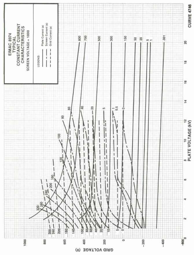
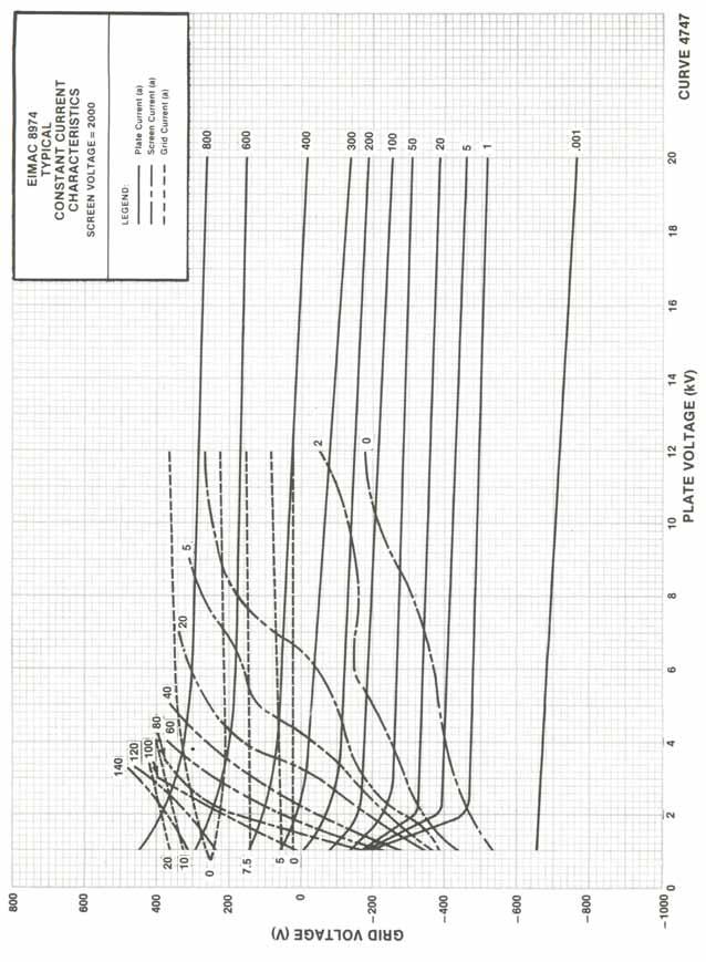
1 TECHNICAL DATA WATER COOLED POWER TETRODE 8974 The EIMAC 8974 is a ceramic/metal, water-cooled power tetrode designed for very high power rf amplification. This tube is used for medium-wave and high frequency broadcast service at output power levels in the megawatt range. The 8974 has a two-section thoriated-tungsten mesh filament mounted on water-cooled supports. The two sections may be fed from an ac or dc power source. The maximum anode dissipation rating is 1500 kilowatts steady state. Large-diameter coaxial terminals are used for the control grid and the rf filament terminals. Filament power and filament support cooling-water connections are made through three special connectors. Anode cooling water connections are made with available hand-tightened fittings with O-ring seals. GENERAL CHARACTERISTICS 1 ELECTRICAL Filament: Mesh, Thoriated-tungsten, two section.voltage V (nominal per section) 640 A Frequency of Maximum Ratings (CW) MHz Amplification Factor, Average, Grid to Screen Direct Interelectrode Capacitances (grounded cathode):.cin pf.cout pf.cgp pf Direct Interelectrode Capacitances (grounded grid) Cin pf.cout pf.cpk pf MECHANICAL Net Weight lbs; 80 kg Gross Weight lbs; 173kg Operating Position...Vertical, Base Down Cooling...Water and Forced Air Maximum Overall Dimensions:.Length in; cm.diameter in; cm Maximum Operating Temperature: Envelope and Ceramic/Metal Seals...200*C Available Filament Power Connector (not supplied with tube):.filament Power/Water Connector (2 req d.):..eimac SK-2310 Filament rf Connector (1 req d):... SK-2315 Available Anode Cooling Water Connectors (not supplied with tube): Note: 2 connectors are required per tube: EIMAC SK-2320, SK-2321, SK-2322, or SK Characteristics and operating values are based on performance tests. These figures may change without notice as a result of additional data or product refinement. CPI/Eimac should be consulted before using this information for final equipment design. 2 Capacitance values shown are nominal, measured with no special shielding, in accordance with Electronic Industries Association Standard RS-191.
2 RADIO FREQUENCY LINEAR AMPLIFIER GRID DRIVEN Class AB ABSOLUTE MAXIMUM RATINGS: DC Anode Voltage DC Screen Voltage DC Grid Voltage DC Anode Current Anode Dissipation Screen Dissipation...15 Grid Dissipation A TYPICAL OPERATION (Below 30 MHz) Anode Voltage dc Screen Voltage Vdc Grid Voltage # Vdc Zero Signal Anode Current* Adc Single Tone Anode Current Adc Single Tone Screen Current* Adc Peak rf Grid Voltage* v Anode Dissipation* Anode Power Output* Anode Load Resistance Ohms Anode Efficiency* % * Approximate Value # Adjust for zero-signal anode current RADIO FREQUENCY POWER AMPLIFIER Class C Telegraphy or FM (Key-down conditions) ABSOLUTE MAXIMUM RATINGS: DC Anode Voltage DC Screen Voltage DC Grid Voltage DC Anode Current Anode Dissipation Screen Dissipation...15 Grid Dissipation A TYPICAL OPERATION (below 30 MHz) Anode Voltage dc Screen Voltage Vdc Grid Voltage Vdc Anode Current Adc Screen Current* Adc Grid Current* Adc Calculated Driving Power Anode Dissipation* Screen Dissipation Grid Dissipation Anode Load Resistance Ohms Anode Power Output* Anode Efficiency* % *Approximate value ANODE MODULATED RADIO FREQUENCY POWER AMPLIFIER Class C Telephony (Carrier conditions) ABSOLUTE MAXIMUM RATINGS: DC Anode Voltage DC Screen Voltage DC Grid Voltage DC Anode Current Anode Dissipation Screen Dissipation...15 Grid Dissipation * Approximate Value A TYPICAL OPERATION: Anode Voltage dc Screen Voltage dc Grid Voltage Vdc Anode Current # Adc Screen Current*... 8 Adc Grid Current* Adc Peak Screen Voltage (100% modulation) v Peak rf Grid Driving Voltage* v Calculated Driving Power W Anode Dissipation* Screen Dissipation Grid Dissipation* Anode Load Resistance Ohms Anode Output Power* Anode Efficiency* % 2 *Approximate value
3 RADIO FREQUENCY POWER AMPLIFIER Doherty Amplifier Service ABSOLUTE MAXIMUM RATINGS: DC Anode Voltage DC Screen Voltage DC Grid Voltage DC Anode Current Anode Dissipation Screen Dissipation...15 Grid Dissipation A Carrier Tube - Carrier Conditions: Anode Voltage dc Screen Voltage dc Grid Voltage* Vdc Anode Current Adc Screen Current* Adc Grid Current* Adc Peak Grid Driving Voltage * V Grid Driving Power* W Anode Power Output* Anode Dissipation* Anode Efficiency* % Anode Load Resistance Ohms TYPICAL OPERATION (Frequencies to 30 MHz): Carrier Tube - Peak of Modulation Peak Tube - Peak of Modulation: DC Anode Voltage DC Screen Voltage DC Grid Voltage* Peak Grid Drive Voltage* Peak Grid Drive Power* Peak Anode Power Out* Anode Load Resistance V V Ohms Peak Grid Drive Voltage* V Peak Grid Driving Power * W Anode Power Output* Anode Load Resistance Ohms Actual Load Resistance at Combining Point =.25.7 Ohms Screen dissipation averaged over a sinusoidal modulation cycle - Modulation Index 1 Carrier Tube Peak Tube *Approximate value NOTE: TYPICAL OPERATION data are obtained from direct measurement or by calculation from published characteristic curves. Adjustment of the rf grid voltage to obtain the specified anode current at the specified bias, screen and anode voltages is assumed. If this procedure is followed, there will be little variation in output power when the tube is changed, even though there may be some variation in grid and screen current. The grid and screen currents which result when the desired anode current is obtained are incidental and vary from tube to tube. These current variations cause no difficulty so long as the circuit maintains the correct voltage in the presence of the variations in current. RANGE VALUES FOR EQUIPMENT DESIGN If, Filament Current, at 16.3 volts ac (Per Section)... Min. Max. Unit A Voltage required to cut off ib, EC 2 = 1.5 dc, EB=15.0 dc V 3
4 APPLICATION MECHANICAL UNPACKING To insure safety of the operator performing the work as well as preventing damage to the tube, the following instructions should be followed when unpacking the tube: 1) Open the crate by removing the lid, first unlocking the toggle bolts in 8 places. 2) Attach a lifting hoist to the lifting loop and raise the tube slightly to support the weight of the tube. 3) Remove 8 bolts securing the mounting brackets to the corners. 4) Using the hoist, lift the tube and place on blocks or on a stand that supports its weight by the bottom of the lower corona ring. 5) Remove the brackets from the tube. HANDLING This product contains a thoriated-tungsten filament, and although of a rugged mesh design, it is relatively fragile and a tube should be protected from shock and vibration. A lifting eye is available at the center of the anode cooler and should be used any time the tube is to be lifted for moving, etc. A lifting device such as a chain hoist may be employed to lift the tube and should be capable of safely supporting the full weight of the tube (in excess of 200 lbs with cooling water in the anode cooler) and should be operated with great care, especially when lowering the tube onto a resting place or into equipment. It is recommended that a thick rubber mat or similar material be used to absorb any undue shock that may occur if the tube is to be placed on a hard surface. STORAGE If a tube is to be stored as a spare it should be kept in its shipping crate and all water should be purged from the anode cooler and from the filament supports/connectors. Prior to shipping, water should be removed from the tube s anode cooler and filament structure. The anode cooler can be drained by inverting the tube. Water should be purged from the internal filament support structure by applying compressed air to one of the filament coolant ports and it is important to note that pressure during this process must be limited to 2 Bar (29 psi). Under no circumstances should an un-regulated air source be used for this procedure. The tube should be stored with a portable VACION pump power supply connected to allow monitoring the tube s vacuum properties (see section on VACION PUMP OPERATION for details.) The original shipping crate with the shock mounts and hardware should be retained in a dry place for future use such as moving a tube over a con-siderable distance. MOUNTING - The 8974 must be mounted vertically, base down. The full weight of the tube should rest on the screen-grid contact flange at the base of the tube and all lifting of the tube should be done with the lifting eye which is attached to the top of the anode cooling jacket. ANODE COOLING - The anode is cooled by circulating water through the structure. The inlet and outlet connections are clearly marked on top of the anode cooling jacket and it is important they be connected only as indicated. Tube life can be seriously compromised by water condition. With contaminated water, deposits will form on the inside of the water jacket, causing localized anode heating and eventual tube failure. To minimize electrolysis and power loss, water resistance at 25 C should always be one megohm per cubic centimeter or higher. The relative water resistance should be periodically checked using readily available instruments. Minimum water flow requirements for the anode are shown in the table for an outlet water temperature not to exceed 70 C and inlet water temperature at 50 C. System pressure should not exceed 100 psi. ANODE WATER APPROX JACKET DISSIPATION FLOW PRESS DROP () (GPM) (PSI) Filament Only
5 This cooling data is applicable to steady-state or transient anode dissipation. At significantly reduced anode dissipation a lower flow rate may be permissible but using the maximum flow rate will protect the tube from unforeseen events that may cause increased anode dissipation. Cooling water must be well filtered (with the equivalent of a 100-mesh screen) to eliminate any solid materials which could block cooling passages, as this would immediately affect cooling efficiency and could produce localized anode overheating and tube failure. EIMAC Application Bulletin #AB-16, Water Purity Requirements in Liquid Cooling Systems is available on request and contains considerable detail on purity requirements and maintenance of systems. BASE COOLING - The tube base requires air cooling with a minimum of 50 cfm of air at 50*C maximum at sea level, directed toward the base seal areas from a general purpose fan. It should be noted that temperatures of the ceramic/metal seals and the lower envelope areas are the controlling and final limiting factor and the maximum allowable temperature is 200*C. Temperature-sensitive paints are available for use in checking temperatures in these areas before equipment design and air-cooling requirements are finalized. EIMAC Application Bulletin AB-20, MEASURING TEMPERATURE OF POWER GRID TUBES, covers this subject in detail and is available on request. Water cooling of the filament and screen grid supports is also required, with inlet water temperature not to exceed 70*C. Each of the two filament connectors include both an inlet and an outlet line, with the proper connector for the inlet water shown on the tube outline drawing. Minimum flow for the F1 connector is 2.0 gpm, at an approximate pressure drop of 12 psi. Minimum flow for the F2 connector is 4.0 gpm, at an approximate pressure drop of 50 psi. The screen grid cooling water is fed by means of 1/4-18 NPT tapped holes shown on the tube outline drawing, with a minimum flow of 2.0 gpm required, at an approximate pressure drop of 12 psi. ALL COOLING MUST BE APPLIED BEFORE OR SIMULTANEOUSLY WITH THE APPLICATION OF ELECTRODE VOLTAGES, INCLUDING THE FILAMENT, AND SHOULD NORMALLY BE MAIN- TAINED FOR SEVERAL MINUTES AFTER ALL VOLTAGES ARE REMOVED TO ALLOW FOR TUBE COOLDOWN. 5 ELECTRICAL ABSOLUTE MAXIMUM RATINGS - Values shown for each type of service are based on the absolute system and are not to be exceeded under any service conditions. These ratings are limited values outside which serviceability of the tube may be impaired. In order not to exceed absolute ratings the equipment designer has the responsibility of determining an average design value for each rating below the absolute value of that rating by a safety factor so that the absolute values will never by exceeded under any usual conditions of supply-voltage variation, load variation, or manufacturing variation in the equipment itself. It does not necessarily follow that combinations of absolute maximum ratings can be attained simultaneously. HIGH VOLTAGE - Normal voltages used with this tube are deadly, and equipment must be designed properly and operating precautions followed. Design all equipment so that no one can come in contact with high voltages. Equipment must include safety enclosures for the high-voltage circuits and terminals, with interlock switches to open primary circuits of the power supply and to discharge high voltage capacitors when access doors are opened. Interlock switches must not be bypassed to allow operating with access doors open. Always remember that HIGH VOLTAGE CAN KILL. FILAMENT OPERATION When cold, the resistance of a thoriated tungsten filament is very low, therefore the initial starting (inrush) current when filament voltage is applied can be many times the normal (hot) current; this can be detrimental to the longevity of a filament structure. Filament inrush current should never exceed a value of twice the nominal rated current. Filament turn-on and turn-off should be programmed. Filament voltage should be smoothly increased from zero to the operating level over a period of two minutes, and a motordriven continuously variable auto-transformer (such as a VARIAC* or a POWERSTAT*) is suggested. Normal turnoff procedure should be a smooth decrease from the operating voltage to zero over a period of two minutes. At rated (nominal) filament voltage the peak emission capability of the tube is many times that needed for most applications. A reduction in filament voltage will lower the filament temperature, which will substantially increase life expectancy. The correct value of filament voltage should be determined for the particular appli-
6 cation. It is recommended the tube be operated at full nominal voltage for an initial stabilization period of from 100 to 200 hours before any action is taken to operate at reduced filament voltage. The voltage should then be reduced gradually until there is slight degradation in performance (such as power output or distortion). For operation the voltage should then be increased several tenths of a volt above the value where performance degradation was noted. The operating point should be rechecked after 24 hours. Filament voltage should be closely regulated when voltage is to be reduced below nominal in this manner, to avoid any adverse influence caused by normal line voltage variations. Black heat operation (a reduction of filament voltage to 50% or less of nominal voltage during standby periods) is not recommended. During standby periods, forced air cooling and water flow must be maintained on the filament supports to ensure the ceramic/metal seal temperature does not exceed 200 C. In addition, anode cooling water flow must be maintained at a rate that ensures the outlet water temperature never exceeds 100 C. See cautionary information regarding hot water on p.10. Serious damage and personal harm can result if water flow is interrupted while power is applied to the filament therefore system interlocks are necessary to remove all power to the tube if coolant flow is not present for any reason. Filament voltage should be measured at the tube base, using an accurate rms-responding meter. Where hum is an important system consideration, it is permissible to operate the filaments with dc rather than ac power. Contact CPI Microwave Power Products EIMAC Operation, Application Engineering for special precautions when using a dc filament supply. Care should be exercised to keep any rf power out of the filament of the tube, as this can cause excessive filament temperature. Both sides of the filament must be bypassed to avoid rf resonance in the filament. This tube is designed for commercial service, with only one off/on filament cycle per day. If additional on/off cycling of filament power is anticipated it is recommended the user contact CPI Microwave Power Products EIMAC Operation, Applications Engineering for additional information. VACION* PUMP OPERATION The tube is supplied with an ion pump permanently mounted on the filament structure at the base (stem). The primary function of 6 this device is to allow monitoring of the condition of the tube vacuum, as shown by an ion current meter. With an operational tube it is recommended the VA- CION pump be operated full time so tube vacuum may be monitored on a continuous basis. A reading of less than 10 uadc should be considered as normal, indicating excellent tube vacuum. In addition to other interlock circuitry it is recommended that full advantage be taken of the VACION pump readout by providing circuitry which will shut down all power to the tube in the event the readout current exceeds 50 uadc. In the event of such a shutdown, the VACION pump should be operated alone until vacuum recovery is indicated by a reading of 10 uadc or less, at which point the tube may again be made operational. If the vacuum current rises again it should be considered as indicating a circuit problem such as some tube element may be over-dissipating and outgassing. The VACION pump requires a positive voltage applied to the center pin of approx Vdc to operate properly. One source for VACION power supplies is Varian, Inc. Varian s web site has several models which may be suitable for use with the Varian model (120 volt ac line) or (220 Volt ac line) appear suitable. Alternatives for Varian power supplies are: HeatWave Labs cathode.com/ and Duniway Stockroom duniway.com/ At the tetrode a coaxial cable is attached to the VA- CION pump and comes attached to the tube as delivered. This cable assy. includes a resistor that prevents the filament current from being shorted to ground. The end of the resistor has a solder lug that is attached using one of the small screws to the magnet assy at the VACION pump. The other end of this cable has a female receptacle (type MHV, also designated mil. UG-1016A/U or Amphenol type 27075). To plug onto this receptacle a male plug type UG- 932/U, also supplied with each tube, is normally used for making up an extender cable of the required length. The other end of the extender cable goes to the VACION power supply; the Varian supplies require a Kings plug (not supplied with the 8974). For info see: and cable type RG-58A/U or Belden 8259 is recommended for this connector.
7 In the case of a tube being held as a spare, it is recommended the VACION pump be operated continuously if possible, otherwise it should be operated periodically to check the condition of tube vacuum and operated as long as necessary to achieve a reading of 10 uadc or lower. Figure 1 on p.10 shows the relationship between tube vacuum and the ion current reading. Electrode voltages, including filament voltage, should never be applied if a reading of 50 uadc or higher is obtained. In the event that poor vacuum cannot be improved by operation of the VACION pump the user should contact CPI Microwave Power Products, EIMAC Operation and review the details with an Applications Engineer. If the tetrode is grid-driven the cathode (and therefore the filament power supply) is generally referenced to dc ground potential, that is no bias voltage or other voltage is applied to the filament. In this case the VA- CION power supply may be used with no isolation and the shield and connector on the VACION cable should be grounded for reasons of electrical safety. If however the tetrode is to be used in grounded-grid (cathodedriven) configuration as is typical in the case of VHF, then rf drive applied to the tube s cathode/filament will also be present on the VACION cable and therefore good rf isolation must be provided to prevent rf power from flowing on this cable. The system designer must therefore incorporate rf filtering on the VACION cable to keep rf energy from passing back into the VACION power supply and its metering circuit; ferrite chokes around the cable may be suitable. The filament supply should be grounded as any dc voltage that is applied between the filament to ground will interfere with proper VACION operation. ANODE OPERATION - The maximum anode dissipation rating of 1500 kilowatts should not be exceeded even for very brief periods during setup or tuning. Anode current which flows at high anode voltages with no rf, such as interpulse idling current, must be avoided by such means as reducing screen voltage or increasing control grid bias during the idling period. Current flowing at high anode voltage generates significant levels of X-Ray radiation. At typical Class AB idling currents, X-Ray intensity is very high and represents a significant potential hazard to personnel in the vicinity of the tetrode. See X-RADIATION HAZARD on p.9 for more information. Operation with low values of anode current under some conditions of high instantaneous anode voltage 7 (such as regulator service or lower power and low impedance tuning conditions) can, as a result of the screen and grid voltages chosen, lead to anode damage and subsequent failure from spot heating as a result of focusing effects in the tube. If operation under such conditions is necessary CPI Microwave Power Products, EIMAC Operation s Application Engineering should be contacted for assistance in selection of operating parameters. GRID OPERATION - The maximum grid dissipation is 4 kilowatts and protective measures should be taken to insure that this rating is not exceeded. Grid dissipation is approximately equal to the product of dc grid current and peak positive grid voltage. A protective spark gap device should be connected between the control grid and the cathode to guard against excessive voltage. Under some operating conditions the control grid may exhibit a negative resistance characteristic. This may occur with high screen voltage when increasing the drive power results in a net decrease in grid current. Large values of negative grid current can cause the amplifier to become regenerative. The driver stage must be designed to tolerate this condition. One technique is to swamp the driver so that the change in load, due to secondary grid emission, is a small percentage of the total driver load. SCREEN OPERATION - The maximum screen grid dissipation is 15 kilowatts. With no ac applied to the screen grid, dissipation is simply the product of dc screen voltage and the dc screen current. Anode voltage, anode loading, or bias voltage must never be removed while filament and screen voltages are present, since screen dissipation ratings will be exceeded. Suitable protective circuitry must be provided to remove screen power in case of a fault condition. A protective spark-gap device should be connected between screen grid and the cathode to guard against excessive voltage. Operation of the 8974 at high screen grid current, even if under low duty pulsed operation, can result in sufficient screen grid heating to cause significant screen grid current. Such operation will not cause tube damage provided proper procedures are followed; however, the screen grid power supply should be designed with this characteristic in mind so that the correct operating voltage will be maintained and tube life will not be compromised.
8 under all conditions. Dangerously high anode current may flow if the screen power supply exhibits a rising voltage characteristic with negative screen current. A current path from the screen to cathode must be provided by a bleeder resistor to absorb the reverse current without allowing the screen grid voltage to rise excessively. A series-regulated power supply can only be used when an adequate bleeder resistor is provided; a shunt-regulated power supply is also very effective towards meeting this requirement. PULSE OPERATION - The thermal time constants of the internal tube elements vary from a few milliseconds in the case of the grids to about 200 milliseconds for the anode. In many applications the meaning of duty as applied to a pulse chain is lost because the interpulse period is very long. For pulse lengths greater than 10 milliseconds, where the interpulse period is more than 10 times the pulse duration, the element dissipations and required cooling are governed by the watt-seconds during the pulse. Provided the wattseconds are less than the listed maximum dissipation rating and sufficient cooling is supplied, tube life will not be compromised. FAULT PROTECTION - In addition to the normal anode over-current interlock and coolant interlock, the tube must be protected from internal damage caused by any arc which may occur. A protective resistance should always be connected in series with the grid and anode to help absorb power supply stored energy if an arc should occur. An electronic crowbar, which will discharge power supply capacitors in a few microseconds after the start of an arc, is required. A maximum of 50 Joules is permitted during an arc but this should be limited to less than that amount if possible. The protection criteria for each supply is to short each electrode to ground, one at a time, through a vacuum relay switch and a 6-inch length of #30 AWG copper wire. The wire will remain intact if proper criteria are met. As noted under GRID OPERATION and SCREEN OPERATION, a protective spark gap should be connected from the control grid to ground and from the screen grid to ground. CPI Application Bulletin #17 titled FAULT PROTECTION contains considerable detail and is available on request. LOAD VSWR Amplifier load VSWR should be monitored and the detected signal used to operate the interlock system to remove anode voltage within 20 milliseconds after a fault occurs. In the case of high stored energy in the load system, care must be taken to avoid excessive return energy from damaging the tube and associated circuit components. MODE SUPPRESSION CONSIDERATIONS Large high-power gridded tubes, including the 8974, have natural circular resonance modes of oscillation which must be suppressed during initial equipment development. The short compact stem structure of EIMAC tubes provides easy access for mode suppression techniques. It is recommended that short pulse testing be used to detect this phenomenon and to evaluate the effectiveness of the suppression techniques used. The 8974 has been found to exhibit internal circular mode oscillations in both L-band and S-band frequency ranges. These TE11 modes must be suppressed externally to prevent damage to the tube and to provide stable operation in the intended application. One technique which has worked to suppress these circular modes is using ferrite tiles. The ferrite tiles can be cemented (using General Electric RTV-102 or equivalent) to the conical and flat surfaces of the screen deck around the base of the tube. The size of the tiles can be up to approximately one inch square or rectangular and 0.1 to 0.3 inch thick. The ferrite must have properties such that the material is effective at the circular mode frequency but not excessively lossy at the fundamental frequency otherwise excessive heating of the ferrite may occur. One source for the ferrite material is: National Magnetics Group, Inc. in Bethlehem, PA, USA. For further information contact CPI Microwave Power Products, EIMAC Operation. In some instances, a compromise between tube efficiency and anode load impedance by way of modifying the output matching circuit will prevent circular mode oscillations from occurring while a tube is delivering peak output. Adjustment of both the screen voltage and grid bias voltage while testing for circular mode oscillations is also predicated, fine adjustments in both parameters will often reduce or eliminate circular mode oscillations. Changing a tube s operating conditions from those initially established for a given application may also lead to the need for re-checking a tube for circular mode oscillations prior to commencing operation under the new conditions. 8
9 X-RADIATION HAZARD - High-vacuum tubes operating at voltages higher than 15 kilovolts produce progressively more dangerous X-ray radiation as the voltage is increased. This tube, operating at its rated voltages and currents, is a potential X-ray source. Only limited shielding is afforded by the tube envelope. Moreover, the X-radiation level may increase significantly with tube aging and gradual deterioration, due to leakage paths or emission characteristics as they are affected by the high voltage. X-ray shielding may be required on all sides of tubes operating at these voltages to provide adequate protection throughout the life of the tube. Periodic checks on the X-ray level should be made, and the tube should never be operated without required shielding in place. If there is any question as to the need for or the adequacy of shielding, an expert in this field should be contacted to perform an X-ray survey. In cases where shielding has been found to be required, operation of equipment with interlock switches cheated and cabinet doors open in order to be better able to locate an equipment malfunction can result in serious X-ray exposure. RADIO-FREQUENCY RADIATION - Avoid exposure to strong rf fields even at relatively low frequency. Absorption of rf energy by human tissue is dependent on frequency. OSHA (Occupational Safety and Health Administration) recommends that prolonged exposure to rf radiation should be limited to 10 milliwatts per square centimeter. INTERELECTRODE CAPACITANCE - The actual internal interelectrode capacitance of a tube is influenced by many variables in most applications, such as stray capacitance to the chassis from the tube terminals and associated wiring. To control the actual capacitance values within the tube, as the key component involved, the industry and military services use a standard test procedure described in Electronic Industries Association Standard RS-191. The test is performed on a cold tube, and in the case of the 8974, with no special shielding. Other factors being equal, controlling internal tube capacitance in this way normally assures good interchangeability of tubes over a period of time. The capacitance values shown in the test specification or technical data are taken in accordance with Standard RS-191. The equipment designer is cautioned to make allowance for the capacitance values, including tube-totube variation and strays, which will exist in any normal application. Measurements should be taken with mounting which represent approximate final layout if capacitance values are highly significant in the design. SPECIAL APPLICATIONS - When it is desired to operate this tube under conditions different from those listed here, write to CPI Microwave Power Products, EIMAC Operation ATTN: Applications Engineering; 607 Hansen Way, Palo Alto, CA USA. 9
10 OPERATING HAZARDS Proper use and safe operating practices with respect to power tubes are the responsibility of equipment manufacturers and users of such tubes. All persons who work with and are exposed to power tubes, or equipment that utilizes such tubes, must take precautions to protect themselves against possible serious bodily injury. DO NOT BE CARE- LESS AROUND SUCH PRODUCTS. The operation of this tube may involve the following hazards, any one of which, in the absence of safe operating practices and precautions, could result in serious harm to personnel. HIGH VOLTAGE Normal operating voltages can be deadly. Remember the HIGH VOLTAGE CAN KILL. LOW-VOLTAGE HIGH-CURRENT CIRCUITS - Personal jewelry, such as rings, should not be worn when working with filament contacts or connectors as a short circuit can produce very high current and melting, resulting in severe burns. RF RADIATION Exposure to strong rf fields should be avoided, even at relatively low frequencies. CARDIAC PACEMAKERS MAY BE AFFECTED. HOT WATER Water used to cool tubes may reach scalding temperatures. Touching or rupture of the cooling system can cause serious burns. HOT SURFACES Surfaces of tubes can reach temperatures of several hundred C and cause serious burns if touched for several minutes after all power is removed. MATERIAL COMPLIANCE - This product and package conforms to the conditions and limitations specified in 49CFR for radioactive material, excepted package-instruments or articles, UN2910. In addition, this product and package contains no beryllium oxide (BeO). Please review the detailed Operating Hazards sheet enclosed with each tube, or request a copy from CPI, Eimac Division Application Engineering at 650/
11
12 12
13
14 14
15 607 Hansen Way, Palo Alto, CA Tel: 650/ Fax: 650/ /12 Printed in USA 15
MEDIUM-MU AIR-COOLED POWER TRIODE 3CX15,000H3
 TECHNICAL DATA MEDIUM-MU AIR-COOLED POWER TRIODE 3CX15,000H3 The EIMAC 3CX15,000H3 is an air cooled, ceramic-metal, medium-mu power triode designed primarily for use in broadcast and industrial radio-frequency
HIGH-MU POWER TRIODE 3CW40,000A7
 TECHNICAL DATA HIGH-MU POWER TRIODE 3CW40,000A7 The EIMAC 3CW40,000A7 is a ceramic/metal power triode designed for use as a high power RF amplifier for industrial and scientific applications. The high-mu
RADIAL BEAM POWER CPI RADIAL 4CW50,000J BEAM POWER TETRODE 4CX20,000C
 The EIMAC is a ceramic/metal power tetrode intended for use as a VHF power amplifier. It features a type of internal mechanical structure which results in high rf operating efficiency. Low rf losses in
MULTI-PHASE COOLED POWER TETRODE
 The EIMAC is a ceramic/metal, multiphase (water/vapor) cooled power tetrode designed for very high power rf service. The has a high density thoriated tungsten mesh filament mounted on water-cooled supports.
HIGH-MU AIR-COOLED POWER TRIODE 3CX1500D7
 TECHNICAL DATA HIGH-MU AIR-COOLED POWER TRIODE 3CX1500D7 The Eimac 3CX1500D7 is a compact power triode with an anode dissipation rating of 1500 watts. This tube features a filament designed to operate
4CM500,000G MULTIPHASE-COOLED POWER TETRODE
 The Eimac is a ceramic/metal high power tetrode designed to be used as an exact replacement for the Thales TH558. This tube has a thoriated-tungsten mesh filament and it uses pyrolytic graphite grids which
LIQUID-COOLED POWER CPI LIQUID-COOLED 4CW50,000J POWER TETRODE 4CW30,000B
 The Eimac is a ceramic/metal power tetrode recommended for rf power amplifier service in industrial and scientific applications. This tube is also useful as a high voltage, high current pulse modulator
YC-179 / YC-179A CPI HIGH-MU 4CW50,000J POWER TRIODE YC-179 / YC-179A
 The Eimac YC-79 is a ceramic/metal high-mu power triode designed for pulsed rf applications. Utilizing beam-forming cathode and control grid geometry, this tube provides the gain of a tetrode with circuit
L A B O R A T O R I E S 9740 COZYCROFT AVENUE * CHATSWORTH * CALIFORNIA (800) * (818) * FAX: (818)
 * (818) * FAX: (818)") 3CPX800A7 Hi-Mu Power Triode The Penta Laboratories 3CPX800A7 is a ceramic and metal power triode intended for use as a radiofrequency amplifi er in FM broadcast applications. Operation with zero grid
3CPX800A7 Hi-Mu Power Triode The Penta Laboratories 3CPX800A7 is a ceramic and metal power triode intended for use as a radiofrequency amplifi er in FM broadcast applications. Operation with zero grid
Svetlana 4CX7500A Radial Beam Power Tetrode
 Svetlana CX7500A Radial Beam Power Tetrode T he Svetlana CX7500A is designed for audio and radio frequency applications. The Svetlana CX7500A has a directly-heated thoriated tungsten mesh filament for
PL8877/ 3CX1500A7 High-Mu Power Triode
 PL8877/ 3CX1500A7 High-Mu Power Triode The Penta Laboratories PL8877/3CX1500A7 is a rugged ceramic and metal power triode designed for use as cathode driven Class AB2 or Class B amplifi er in audio or
TECHNIlCAL DATA. Amperes Cathode Heating Time..300
 TECHNIlCAL DATA TRIODE The BIMAC Y-810 tube has been specifically designed for high voltage series regulator or switch tube (modulator) service. The compact, rugged design has very low internal inductance
4-400C/6775 Radial Beam Power Tetrode
 Radial Beam Power Tetrode The Amperex 4-400C/6775 is a compact, ruggedly constructed, broadcast quality tetrode having a maximum plate dissipation rating of 400 watts. It is intended for use as an amplifier,
9007 Power Tube. VHF Linear Power Amplifier Tube 33 Kilowatt Peak Sync Output Thru VHF-TV Band
 9007 Power Tube VHF Linear Power Amplifier Tube 33 Kilowatt Peak Sync Output Thru VHF-TV Band 14 db Gain High Gain-Bandwidth Products Efficient Forced-Air Cooling Full Input to 400 MHz CERMOLOX Construction
4X150A/7034 Radial Beam Power Tetrode
 4X15A/734 Radial Beam Power Tetrode T The Svetlana 4X15A/734 is a compact radial beam tetrode. The 4X15A is intended for Class AB SSB linear RF amplifier service. It is intended for stationary and mobile
8988 Power Tube. Linear Beam Power Tube
 8988 Power Tube Linear Beam Power Tube CERMOLOX Tube High Gain-Bandwidth Product Full Input to 400 MHz 7000 W Peak Sync. Output Through VHF-TV Band with 16 db Gain The BURLE 8988 is designed specifically
Power Tube. Beam Power Tube
 8977 Power Tube Beam Power Tube - 7 kw Aural Output Through VHF-TV Band - 19 db Gain - CERMOLOX Beam Power Tube - Full Input to 400 MHz - Forced-Air Cooled The BURLE 8977 is intended specifically to meet
8984 Power Tube. VHF Linear Beam Power Tube
 8984 Power Tube HF Linear Beam Power Tube Full Input to 300 MHz Forced-Air Cooled 55 kw Peak Sync. Output HF-T Band 16dB Gain FM Broadcast Service 55 kw Output 16dB Gain The BURLE 8984 is designed specifically
8807 Power Tube. Beam Power Tube
 8807 Power Tube Beam Power Tube CERMOLOX Beam Power Tube Full Input to 400 MHz Forced-Air-Cooled 17.6 kw Peak Sync Output VHF-TV Band 13 db Gain Single Sideband 15 kw PEP 20 db Gain FM Broadcast Service
PET1606J2F. Pilani Electron Tubes & Devices Pvt. Ltd. Water Cooled Triode. For Industrial RF Heating. Drop in equivalent of BW1606J2F
 Water Cooled Triode For Industrial RF Heating Drop in equivalent of BW1606J2F Output Power: 30 kw Anode voltage: 10 kv max Anode dissipation: 15 kw max Frequency up to 30 MHz Manufactured in India, in
8072 Power Tube. VHF Linear Amplifier Tube. Coaxial-Electrode Structure Ceramic-Metal Seals Full Input to 500 MHz Conduction Cooled
 8072 Power Tube VHF Linear Amplifier Tube Coaxial-Electrode Structure Ceramic-Metal Seals Full Input to 500 MHz Conduction Cooled The BURLE 8072 is a small, conduction cooled beam power tube designed for
8791 Power Tube. Linear Beam Power Amplifier Tube
 8791 Power Tube Linear Beam Power Amplifier Tube Ruggedized, Reliable 80 Watt Average-Noise-Power Output with White Noise Loading 250 Watt Power Output in VHF-Linear Translator Service 500 Watt PEP Output
8121 Power Tube. Linear Beam Power Tube
 8121 Power Tube Linear Beam Power Tube Coaxial-Electrode Structure Ceramic-Metal Seals Full Ratings up to 500 MHz Forced-Air Cooled 170 Watts PEP Output at 30 MHz 235 Watts CW Output at 470 MHz The BURLE
PET1610F. Pilani Electron Tubes & Devices Pvt. Ltd. Forced-Air Cooled Triode. For Industrial RF Heating. Drop in equivalent of BW1610F
 Forced-Air Cooled Triode For Industrial RF Heating Drop in equivalent of BW1610F Output Power: 30 kw Anode voltage: 9 kv max Anode dissipation: 10 kw max Frequency up to 30 MHz Manufactured in India, in
6884 Power Tube. Beam Power Tube
 6884 Power Tube Beam Power Tube - CERMOLOX - Oxide-Coated Cathode - Forced-Air Cooled - 80 Watts CW Power Output at 400 MHz - 40 Watts CW Power Output at 1215 MHz BURLE-6884 is a compact, forced-air cooled
4662 Power Tube. Linear Beam Power Tube
 4662 Power Tube Linear Beam Power Tube Ruggedized Full Ratings to 500 MHz 300 W CW Output @ 470 MHz 380 W PEP Output @ 30 MHz Forced-Air Cooled Ceramic-Metal Seals Coaxial Electrodes The BURLE 4662 is
8792 Power Tube. Linear Beam Power Amplifier Tube
 8792 Power Tube Linear Beam Power Amplifier Tube 1000 Watts Peak Sync Output in VHF Translator Service 265 Watt Average-Noise-Power Output with White Noise Loading 300 Watt Power Output in UHF-Linear Telephony
X-band Magnetron. Cooling (note 5) Water Output coupling (note 6) UG51/U Magnet (note 7) Integral, Permanent
 Water Output coupling (note 6) UG51/U Magnet (note 7) Integral, Permanent") X-band Magnetron GENERAL DESCRIPTION MX7637 is a tunable X-band pulsed type magnetron intended primarily for linear accelerator. It is cooled with water and has a UG51/U (WR112) output coupling. It is
X-band Magnetron GENERAL DESCRIPTION MX7637 is a tunable X-band pulsed type magnetron intended primarily for linear accelerator. It is cooled with water and has a UG51/U (WR112) output coupling. It is
X band Magnetron. Water: Anode cavity Forced-air: Input ceramics and terminals Output coupling (note 6) UG51/U Magnet (note 7) Integral, Permanent
 UG51/U Magnet (note 7) Integral, Permanent") X band Magnetron GENERAL DESCRIPTION MX7621 is a tunable X-band pulsed type magnetron intended primarily for linear accelerator. It is cooled with water and has a UG51/U (WR112) output coupling. It is
X band Magnetron GENERAL DESCRIPTION MX7621 is a tunable X-band pulsed type magnetron intended primarily for linear accelerator. It is cooled with water and has a UG51/U (WR112) output coupling. It is
Svetlana 3CX3000F7/8162 High-Mu Power Triode
 High-Mu Power Triode T he Svetlana 3CX3F7/8162 is a high-performance ceramic/metal power triode designed for use in zero-bias, class AB, or class B RF or audio amplifiers. A modern mesh filament is used,
MG7095 Tunable S-Band Magnetron
 MG7095 Tunable S-Band Magnetron The data should be read in conjunction with the Magnetron Preamble and with British Standard BS9030 : 1971. ABRIDGED DATA Mechanically tuned pulse magnetron intended primarily
MG5223F S-Band Magnetron
 MG5223F S-Band Magnetron The data should be read in conjunction with the Magnetron Preamble. ABRIDGED DATA Fixed frequency pulse magnetron. Operating frequency... 3050 ± 10 MHz Typical peak output power...
General Data Electrical Heater for Oxide-Coated Unipotential Cathode: Voltage (AC or DC) 26.5 ± 10% Current at 26.5 volts
 26.5 ± 10% Current at 26.5 volts") 7843 Power Tube Conduction-Cooled UHF Beam Power Tube Cermolox Construction Oxide-Coated Cathode Conduction Cooled Peak Power Output: 400 MHz - 80 W 1215 MHz-40W BURLE 7843 is a compact, conduction-cooled
7843 Power Tube Conduction-Cooled UHF Beam Power Tube Cermolox Construction Oxide-Coated Cathode Conduction Cooled Peak Power Output: 400 MHz - 80 W 1215 MHz-40W BURLE 7843 is a compact, conduction-cooled
4665 Power Tube UHF Pulsed Power Amplifier Tube
 4665 Power Tube UHF Pulsed Power Amplifier Tube Cermolox Forced-Air-Cooled Coaxial Terminals Full Input to 1215 MHz 65kW Peak Pulsed Power Output Controlled Interelectrode Capacity The BURLE 4665 is designed
Abridged Data. General Data. MG7095 Tunable S-Band Magnetron for Switched Energy Applications. Cooling. Electrical. Accessories.
 The data should be read in conjunction with the Magnetron Preamble and with British Standard BS9030: 1971 Abridged Data Mechanically tuned pulse magnetron intended primarily for linear accelerators. Frequency
Western Electric D V a c u u m T u b e
 284D Western Electric 2 8 4 D V a c u u m T u b e Classification Fiiamentary air-cooied triode The tube is designed primarily for use as an audio-frequency amplifier or modulator and may be used as a replacement
BTM Series Pulsed RF Power Amplifier Modules. Application Note
 BTM Series Pulsed RF Power Amplifier Modules Application Note Tomco BT Series Pulsed RF Amplifier Modules - Application note Contents Contents...2 Amplifier Safety Precautions...3 Hazardous Materials Warning:...4
M5028 Precision Tuned Magnetron
 M5028 Precision Tuned Magnetron The data should be read in conjunction with the Magnetron Preamble. ABRIDGED DATA Precision tuned pulse magnetron for linear accelerators. The tuning drive will mechanically
2 5 1 A Va c u u m T u b e
 251A 2 5 1 A Va c u u m T u b e P L A T E L E A D INSULATORS W SPRING CONNECTOR - P L A T E L E A D -FILAMENT LEADS CONNECTOR GRID LEAD Classification The 251A Vacuum Tube is a three element, air-cooled,
E2V Technologies MG5223F S-Band Magnetron
 E2V Technologies MG5223F S-Band Magnetron The data should be read in conjunction with the Magnetron Preamble. ABRIDGED DATA Fixed frequency pulse magnetron. Operating frequency..... 3050 + 10 MHz Typical
8791/V1 Power Tube. VHF-TV Amplifier Tube
 8791/1 Power Tube HF-T Amplifier Tube CERMOLOX Ruggedized, Reliable Matrix Oxide Cathode Full Input to 400 MHz 1000 Peak Sync Output in HF-T Service The BURLE 8791/1 is designed specifically to meet the
E2V Technologies MG5222 X-Band Magnetron
 E2V Technologies MG5222 X-Band Magnetron The data should be read in conjunction with the Magnetron Preamble. ABRIDGED DATA Fixed frequency pulse magnetron. Direct replacement for the M5039, being mechanically
E2V Technologies M5187F X-Band Magnetron
 E2V Technologies M5187F X-Band Magnetron The data should be read in conjunction with the Magnetron Preamble. ABRIDGED DATA Fixed frequency pulse magnetron. It is a direct replacement for the M515 but offers
MG5193 Tunable S-Band Magnetron
 MG5193 Tunable S-Band Magnetron The data should be read in conjunction with the Magnetron Preamble and with British Standard BS9030 : 1971. ABRIDGED DATA Mechanically tuned pulse magnetron intended primarily
MG6090 Tunable S-Band Magnetron
 MG6090 Tunable S-Band Magnetron The data should be read in conjunction with the Magnetron Preamble and with British Standard BS9030 : 1971. ABRIDGED DATA Mechanically tuned pulse magnetron intended primarily
E2V Technologies MG6028 Fast Tuned Magnetron
 E2V Technologies MG6028 Fast Tuned Magnetron The data should be read in conjunction with the Magnetron Preamble. ABRIDGED DATA Fast tuned pulse magnetron for linear accelerators. The tuning drive will
YD1195/8913 YD1197/8937 RF Power Triodes
 YD1195/8913 YD1197/8937 RF Power Triodes The YD1195/8913 and YD1197/8937 are RF power triodes in metal-ceramic construction intended for use as industrial oscillators. The YD1195 is forced-air cooled.
Western E/ectrk A V a c u u m T u b e
 295A Western E/ectrk 2 9 5 A V a c u u m T u b e Classification Filamentary air- cooled triode May be used as an audio-frequency amplifier or as a radio-frequency amplifier, modulator o r o s c i l l a
2 5 4 A V a c u u m T u b e
 V a c u u m T u b e 2 5 4 A V a c u u m T u b e Classification The No. 254A Vacuum Tube is a four-element, screen-grid tube for use as a radio-frequency power-amplifier and as a harmonic-generator at intermediate
PERFORMANCE SPECIFICATION SHEET ELECTRON TUBE, NEGATIVE GRID (MICROWAVE) TYPE /
 TYPE /") INCH-POUND MIL-PRF-1/1756B 18 October 2002 SUPERSEDING MIL-PRF-1/1756A 22 August 1997 PERFORMANCE SPECIFICATION SHEET ELECTRON TUBE, NEGATIVE GRID (MICROWAVE) TYPE 8964 1/ This specification is approved
INCH-POUND MIL-PRF-1/1756B 18 October 2002 SUPERSEDING MIL-PRF-1/1756A 22 August 1997 PERFORMANCE SPECIFICATION SHEET ELECTRON TUBE, NEGATIVE GRID (MICROWAVE) TYPE 8964 1/ This specification is approved
Filament Thoriated tungsten. Filament voltage...14 volts Nominal filament current... 6 amperes Average thermionic emission...
 Classification Filamentary Air-cooled Triode. Application May be used as an audio-frequency amplifier or modulator; or as a radiofrequency oscillator or amplifier. Dimensions Large four-pin bayonet base
S-band Magnetron. Tuner revolutions to cover frequency range 4.75 (note 3) Mounting position (note 4) Any Cooling (note 5) Water
 Mounting position (note 4) Any Cooling (note 5) Water") S-band Magnetron GENERAL DESCRIPTION is a mechanical tuned pulsed type S-band magnetron intended primarily for linear accelerator. It is water cooled and has circle waveguide output type. It is designed
S-band Magnetron GENERAL DESCRIPTION is a mechanical tuned pulsed type S-band magnetron intended primarily for linear accelerator. It is water cooled and has circle waveguide output type. It is designed
E2V Technologies CX1175C Deuterium-Filled Ceramic Thyratron
 E2V Technologies CX1175C Deuterium-Filled Ceramic Thyratron The data to be read in conjunction with the Hydrogen Thyratron Preamble. ABRIDGED DATA Deuterium-filled two gap thyratron with ceramic envelope,
PERFORMANCE SPECIFICATION SHEET ELECTRON TUBE, POWER TYPE 8660
 INCH-POUND MIL-PRF-1/1648D 23 September 2014 SUPERSEDING MIL-PRF-1/1648C w/amendment 1 10 April 2008 DESCRIPTION: Tetrode, ceramic-metal. See figure 2. Mounting position: Any. PERFORMANCE SPECIFICATION
PERFORMANCE SPECIFICATION SHEET ELECTRON TUBE, POWER TYPES 7203 AND 7203A
 INCH-POUND MIL-PRF-1/889K 20 January 2015 SUPERSEDING MIL-PRF-1/889J w/ AMENDMENT 2 9 June 2009 PERFORMANCE SPECIFICATION SHEET ELECTRON TUBE, POWER TYPES 7203 AND 7203A This specification is approved
M5187 X-Band Magnetron
 M5187 X-Band Magnetron The data should be read in conjunction with the Magnetron Preamble MXIMUM ND MINIMUM RTINGS BRIDGED DT These ratings cannot necessarily be used simultaneously, and no individual
E2V Technologies CX1725, CX1725X Liquid Cooled, Hollow Anode, Two-Gap Metal/Ceramic Thyratrons
 E2V Technologies CX1725, CX1725X Liquid Cooled, Hollow Anode, Two-Gap Metal/Ceramic Thyratrons The data to be read in conjunction with the Hydrogen Thyratron Preamble. ABRIDGED DATA Hollow anode, deuterium-filled
MC450/MC650 (MC750) OPERATING INSTRUCTIONS
 OPERATING INSTRUCTIONS") MC450/MC650 (MC750) OPERATING INSTRUCTIONS MC 2 AUDIO Ltd., Units 6 & 7 Kingsgate, Heathpark Industrial Estate, HONITON, Devon EX14 1YG England Tel: ++(0)1404.44633 Fax: ++(0)1404.44660 www.mc2-audio.co.uk
MC450/MC650 (MC750) OPERATING INSTRUCTIONS MC 2 AUDIO Ltd., Units 6 & 7 Kingsgate, Heathpark Industrial Estate, HONITON, Devon EX14 1YG England Tel: ++(0)1404.44633 Fax: ++(0)1404.44660 www.mc2-audio.co.uk
731A seismic accelerometer and P31 power unit/amplifier Operating guide
 731A seismic accelerometer and P31 power unit/amplifier Operating guide Caution: This manual should be read carefully before installation. Wilcoxon Sensing Technologies 8435 Progress Drive, Frederick,
Broadband Power Amplifier
 601L Broadband Power Amplifier HIGH RF VOLTAGES MAY BE PRESENT AT THE OUTPUT OF THIS UNIT. All operating personnel should use extreme caution in handling these voltages and be thoroughly familiar with
A 100-Watt Transmitter Using a Pair of VT1625s
 12/16/2007 6:00 PM VT1625 100 Watt Transmitter A 100-Watt Transmitter Using a Pair of VT1625s FIG. 10.6 A 100-watt transmitter for five bands, using salvaged TV power transformer and surplus 1625 amplifier
CX1140 Hydrogen Thyratron
 CX1140 Hydrogen Thyratron The data to be read in conjunction with the Hydrogen Thyratron Preamble. ABRIDGED DATA Hydrogen-filled tetrode thyratron, featuring low jitter and low anode delay time drift.
DSM Dynamic Shunt
 DSM Dynamic Shunt 401-30286-00 Installation Manual Part Number 108-31058-00 Giddings & Lewis Controls, Measurement & Sensing NOTE Progress is an on going commitment at Giddings & Lewis. We continually
PA8HF power amplifier Operating guide
 PA8HF power amplifier Operating guide Wilcoxon Sensing Technologies 8435 Progress Drive, Frederick, MD 21701, USA Amphenol (Maryland), Inc d/b/a Wilcoxon Sensing Technologies Tel: +1 (301) 330-8811 Tel:
APPLICATION NOTE LZY-2 ULTRA LINEAR RF AMPLIFIER. 500 MHz MHz 20 WATTS MIN., 1 db COMPRESSION (40 db MIN. GAIN)
") AN-60-005 APPLICATION NOTE LZY-2 ULTRA LINEAR RF AMPLIFIER 500 MHz - 1000 MHz 20 WATTS MIN., 1 db COMPRESSION (40 db MIN. GAIN) Reviewed by: Jack Semizian Radha Setty INTERNET http://www.minicircuits.com
AN-60-005 APPLICATION NOTE LZY-2 ULTRA LINEAR RF AMPLIFIER 500 MHz - 1000 MHz 20 WATTS MIN., 1 db COMPRESSION (40 db MIN. GAIN) Reviewed by: Jack Semizian Radha Setty INTERNET http://www.minicircuits.com
411LA Broadband Power Amplifier
 411LA Broadband Power Amplifier HIGH RF VOLTAGES MAY BE PRESENT AT THE OUTPUT OF THIS UNIT. All operating personnel should use extreme caution in handling these voltages and be thoroughly familiar with
Instruction Manual OM3500 HF SHORTWAVE POWER AMPLIFIER. OM POWER, s. r. o Bác 126 SLOVAKIA
 Instruction Manual OM3500 HF SHORTWAVE POWER AMPLIFIER OM POWER, s. r. o. 930 30 Bác 126 SLOVAKIA Important safety instructions: The amplifier contains high voltage circuits. Never turn the amplifier on
MG MW S-Band Magnetron
 MG8076 7.5 MW S-Band Magnetron This data should be read in conjunction with the Magnetron Preamble. ABRIDGED DATA Peak power output...7.5 MW Centre frequency...2998 MHz Magnet...integral magnet or separate
100W Wide Band Power Amplifier 6GHz~18GHz. Parameter Min. Typ. Max. Min. Typ. Max. Units. Frequency Range GHz Gain db
 100W Wide Band Power Amplifier 6GHz~18GHz Features Wideband Solid State Power Amplifier Psat: +50dBm Gain: 75 db Typical Supply Voltage: +48V On board microprocessor driven bias controller. Electrical
PERFORMANCE SPECIFICATION SHEET ELECTRON TUBE, NEGATIVE GRID (MICROWAVE) TYPE /
 TYPE /") INCH-POUND MIL-PRF-1/1757B 18 October 2002 SUPERSEDING MIL-PRF-1/1757A(NAVY) 5 September 1997 PERFORMANCE SPECIFICATION SHEET ELECTRON TUBE, NEGATIVE GRID (MICROWAVE) TYPE 8965 1/ This specification is
INCH-POUND MIL-PRF-1/1757B 18 October 2002 SUPERSEDING MIL-PRF-1/1757A(NAVY) 5 September 1997 PERFORMANCE SPECIFICATION SHEET ELECTRON TUBE, NEGATIVE GRID (MICROWAVE) TYPE 8965 1/ This specification is
Preliminary Ver. 1.16A
 ALPHA 9500 HF Power Amplifier Test Report for Grant of Certification for Use in Part 97 Amateur Service under the Rules of the Federal Communications Commission DGVPA-77DF February 23, 2010 Submitted by:
VHF LAND MOBILE SERVICE
 RFS21 December 1991 (Issue 1) SPECIFICATION FOR RADIO APPARATUS: VHF LAND MOBILE SERVICE USING AMPLITUDE MODULATION WITH 12.5 khz CARRIER FREQUENCY SEPARATION Communications Division Ministry of Commerce
The AMK 15-2 is a high-power metal/ceramic triode, intended for use in industrial generators for frequencies
 HIGH POWER TRIODE The is a high-power metal/ceramic triode, intended for use in industrial generators for frequencies up to 120 MHz and output power up to 63 kw in CW mode. Cooling is accomplished by water.
A 75-Watt Transmitter for 3 Bands Simplified Shielding and Filtering for TVI BY DONALD H. MIX, W1TS ARRL Handbook 1953 and QST, October 1951
 A 75-Watt Transmitter for 3 Bands Simplified Shielding and Filtering for TVI BY DONALD H. MIX, W1TS ARRL Handbook 1953 and QST, October 1951 The transmitter shown in the photographs is a 3-stage 75-watt
Wilcoxon Research PA8HF power amplifier Operating guide
 Wilcoxon Research PA8HF power amplifier Operating guide Meggitt Sensing Systems 20511 Seneca Meadows Parkway, Germantown MD 20876, USA Meggitt (Maryland), Inc d/b/a Meggitt Sensing Systems 97012 Rev C.1
Continental's 816R -5B, 35 kw Single Tube Broadcast Transmitter. Includes the 802A solid -state exciter
 Continental's 816R -5B, 35 kw Single Tube Broadcast Transmitter Includes the 802A solid -state exciter LED status indicators Features SCR Power Control Automatic RF Power Output Control Automatic SWR Circuit
COMMANDER HF-2500 COMMANDER HF-2500 MAGNUM. Owner s Manual. PALSTAR, INC. Command Technologies Division 9676 N. Looney Road Piqua, Ohio U.S.A.
 COMMANDER HF-2500 COMMANDER HF-2500 MAGNUM Owner s Manual PALSTAR, INC. Command Technologies Division 9676 N. Looney Road Piqua, Ohio 45356 U.S.A. Customer Service and Sales Telephone: 800-773-7931 International:
Frequency Range: MHz. Efficiency: 10% Temperature Range: 0 to 60 C Max VSWR: 5:1. Class: Supply Voltage: 28.0V
 Part Number Revision 1.c Release Date July 24, 2007 Revision Notes Amplifier Name Technical Specifications Summary Frequency Range: 50-88 MHz P1dB: 60 Watts CW Class: A Supply Voltage: 28.0V Gain: 36dB
RF Power Amplifier (RFPA) Designing a 'Output Tank Circuit'
 Designing a 'Output Tank Circuit'") RF Power Amplifier (RFPA) Designing a 'Output Tank Circuit' By Larry E. Gugle K4RFE, RF Design, Manufacture, Test & Service Engineer (Retired) Figure-1 Output 'Tank' Circuit Network in Low-Pass Filter
RF Power Amplifier (RFPA) Designing a 'Output Tank Circuit' By Larry E. Gugle K4RFE, RF Design, Manufacture, Test & Service Engineer (Retired) Figure-1 Output 'Tank' Circuit Network in Low-Pass Filter
Frequency Range: MHz. Efficiency: 80% Temperature Range: -20 to 65 C Max VSWR: 3:1. Class: Supply Voltage: 32.0V
 Part Number Revision 0.B Release Date October 19, 2007 Revision Notes Final production release Amplifier Name Technical Specifications Summary Frequency Range: 86-108 MHz P1dB: 500 Watts CW Class: C Supply
90 Siemens Aktiengesellschaft
 YL 1011/YL 1012 FRAME4/home/SMC-Archiv-DB/GG-RO-engl/DB-Senderoehren-96_BNR-B442-P4213-X-X- For single-sideband transmitters and TV transmitters Coaxial metal-ceramic tetrode for frequencies up to 250
Transmitter Tetrode. Approx. weight 16 kg. 360 Siemens Aktiengesellschaft. ➀ Tube support ➁ Air inlet ➂ Do not use as terminal.
 Transmitter Tetrode RS 2795 Ordering code Q53-X2795 Coaxial metal-ceramic tetrode, forced-air-cooled, for frequencies up to 110 MHz, particularly suitable for single-sideband communications transmitters
Ultra Wide Band Low Noise Amplifier GHz. Electrical Specifications, TA = +25⁰C, With Vg= -5V, Vcc = +4V ~ +7V, 50 Ohm System
 Ultra Wide Band Low Noise Amplifier 0.5 46GHz Parameter Min. Typ. Max. Min. Typ. Max. Units Frequency Range 0.5 20 20 46 GHz Gain 13 13 db Gain Variation Over Temperature (-45 ~ +85) ±3 ±2 db Noise Figure
S-band 500kW Magnetron
 S-band 500kW Magnetron GENERAL DESCRIPTION M1901A is a mechanically tunable frequency pulsed type S-band magnetron designed to operate in the frequency range of 2.7 GHz to 2.9 GHz with a peak output power
4W Ultra Wide Band Power Amplifier 0.1GHz~22GHz
 4W Ultra Wide Band Power Amplifier 0.1GHz~22GHz Features Wideband Solid State Power Amplifier Gain: 40 db Typical Psat: +37 dbm Typical Noise Figure: 3dB Typical Supply Voltage: +24V (-NP) / +36V (-WP)
Device Interconnection
 Device Interconnection An important, if less than glamorous, aspect of audio signal handling is the connection of one device to another. Of course, a primary concern is the matching of signal levels and
WATERFLUX 3000 Quick Start
 WATERFLUX 3000 Quick Start Electromagnetic flow sensor The documentation is only complete when used in combination with the relevant documentation for the signal converter. KROHNE CONTENTS WATERFLUX 3000
USER MANUAL GOLDMUND MIMESIS 29M Millennium Edition Power Amplifier
 USER MANUAL GOLDMUND MIMESIS 29M Millennium Edition Power Amplifier CONGRATULATIONS Thank you for purchasing the Goldmund Mimesis 29M Millennium Edition. You have acquired the best Analogue Power Amplifier
USER MANUAL. Maxwell Technologies BOOSTCAP Energy Storage Modules. User Manual for 15V Modules: 20 F, 23 F, 53 F, 58 F 15 Volts DC
 USER MANUAL Maxwell Technologies BOOSTCAP Energy Storage Modules User Manual for 15V Modules: 20 F, 23 F, 53 F, 58 F 15 Volts DC BPAK0020 P015 B1 BPAK0023 E015 B1 BPAK0052 P015 B1 BPAK0052 P015 B2 BPAK0058
Austin AUSTIN ISOLATION TRANSFORMER (DUAL WINDING SERIES) Installation Instructions for
 Installation Instructions for") Austin Installation Instructions for AUSTIN ISOLATION TRANSFORMER (DUAL WINDING SERIES) Austin Insulators Inc. 70 Airport Road Mississauga, Ontario LT H, CANADA tel: (90) 0-; fax: (90) 0-0 e-mail: support@austin-insulators.com
Austin Installation Instructions for AUSTIN ISOLATION TRANSFORMER (DUAL WINDING SERIES) Austin Insulators Inc. 70 Airport Road Mississauga, Ontario LT H, CANADA tel: (90) 0-; fax: (90) 0-0 e-mail: support@austin-insulators.com
8W Wide Band Power Amplifier 1GHz~22GHz
 8W Wide Band Power Amplifier 1GHz~22GHz Features Wideband Solid State Power Amplifier Gain: 50 db Typical Psat: +39 dbm Supply Voltage: +36V Electrical Specifications, T A = +25⁰C Typical Applications
LBI-30398N. MAINTENANCE MANUAL MHz PHASE LOCK LOOP EXCITER 19D423249G1 & G2 DESCRIPTION TABLE OF CONTENTS. Page. DESCRIPTION...
 MAINTENANCE MANUAL 138-174 MHz PHASE LOCK LOOP EXCITER 19D423249G1 & G2 LBI-30398N TABLE OF CONTENTS DESCRIPTION...Front Cover CIRCUIT ANALYSIS... 1 MODIFICATION INSTRUCTIONS... 4 PARTS LIST AND PRODUCTION
Rotating Anode X-Ray Tube Housing Assembly. General Data
 Display Devices & Components Company TECHNICAL DATA ROTANODE TM E7252X Rotating Anode X-Ray Tube Housing Assembly! High speed rotating anode X-ray tube housing assembly for high energy radiographic and
MOXTEK. 50kV 10 Watt MAGNUM X-ray Source. X-ray Sources. Contents
 X-ray Sources 0kV 10 Watt MAGNUM X-ray Source Manual Contents MAGNUM X-ray Source Characteristics Initial Inspection and Handling Tube Setup Operating Conditions Operating Precautions and Warnings Operating
TOA PROFESSIONAL POWER AMP
 Operating Instruction Manual TOA PROFESSIONAL POWER AMP Model P-150M, P-300M TOA ELECTRIC CO, LTD. KOBE, JAPAN Contents Precautions... 2 General Description... 2 Features... 3 Specifications... 4~5 Performance
Transmitter Tetrode RS 1034
 For frequencies up to 960 MHz Coaxial metal-ceramic tetrode with integrated resonance suppression, forced-air-cooled or vaporcondensation-cooled, particularly suitable for TV transmitters, band IV/V. Forced-air-cooled
VXR S SERIES 1.0 DESCRIPTION 1.1 FEATURES 1.2 COMPLIANCE 1.3 PACKAGING 1.4 SIMILAR PRODUCTS AND ACCESSORIES
 VXR15-2800S SERIES HIGH RELIABILITY COTS DC-DC CONVERTERS Models Available Input: 9 V to 60 V continuous, 6 V to 100 V transient 15 W, single output of 3.3 V, 5 V, 12 V, 15 V -55 C to 105 C Operation 1.0
WATERFLUX 3000 Quick Start
 WATERFLUX 3000 Quick Start Electromagnetic flowmeter The documentation is only complete when used in combination with the relevant documentation for the signal converter. KROHNE CONTENTS WATERFLUX 3000
20W Solid State Power Amplifier 6-18GHz. Parameter Min. Typ. Max. Min. Typ. Max. Units
 7-3 RF-LAMBDA 20W Solid State Power Amplifier 6-18GHz Electrical Specifications, TA = +25⁰C Vcc = +36V Features Psat: + 43.5dBm Gain: 51 db Supply Voltage: +36V 50 Ohm Matched Short Haul / High Capacity
5W Ultra Wide Band Power Amplifier 2-18GHz. Parameter Min. Typ. Max. Min. Typ. Max. Units
 7-3 RF-LAMBDA 5W Ultra Wide Band Power Amplifier 2-18GHz Features Wideband Solid State Power Amplifier Psat: + 37dBm Gain: 35 db Supply Voltage: +24V Electrical Specifications, T A = +25⁰C, Vcc = +24V