BC346XT. The Complete Reference
|
|
|
- Mae Harmon
- 6 years ago
- Views:
Transcription
1 BC346XT The Complete Reference This document provides a complete reference to all menus, functions, and features of the BC346XT Handheld Trunk Tracker Scanner from Uniden. It is based on the Operation Specification that is used both as a guide to the software engineers for creating the scanner s user interface and as a repository for the final say on how every feature and function is implemented. Some proprietary information has been removed, formatting has been modified, and extensive editing has been performed to make the text more readable. However, you will almost certainly find a handful of odd turns of phrases. Mostly, though, we hope that this reference work can help you better understand and use your BC346XT. This document isn t intended to be a guide for how to use your scanner you ll find that information in the Owner s Manual but rather a reference for all the things that the scanner does. Combined with the Owner s Manual and the great resources available to scanner users online, you now have more information than ever on every facet of your scanner Uniden Corporation Fort Worth, TX All Rights Reserved. 1
2 Contents Feature Summary... 8 Band Coverage... 8 Channels... 9 Memory Architecture... 9 Channel Memory Scan... 9 Priority Scan... 9 Priority Plus Scan... 9 Search with Scan... 9 Scan Speed... 9 Scanning Lockout Temporary Lockout Quick Keys Startup Configuration Channel Alert Alpha Tagging Duplicate Input Alert Number Tag Trunk Tracking Multi-Site System Control Channel Only Priority ID Scanning Preemptive Priority ID Scanning Trunking Activity Indicators Custom Search Quick Search Frequency Autostore Search Speed / Turbo Search Search Lockout Search Key Service Search Broadcast Screen Attenuator Code Search Volume Offset IF Exchange Dropout Delay
3 Weather and SAME Alert Close Call Frequency Capture Close Call Temporary Store Tone-Out Sequential Decode Location-Based Scanning* Location Alert System* Navigation Modes* GPS Compatibility* Wired Cloning Band Scope PC Control LCD and Keypad Backlight Alert Tone Level Battery Low Alert Battery Save Key Lock Key Safe Mode Repeater Reverse Memory Backup Design Controls and Keys Displays LCD Design Icons Dot Matrix LCD Flashing Time Tones General Tones Weather Alert Sirens Tones in Menu Mode Selecting a menu item Editing a name or a frequency etc Alert in Scanner Mode Alert in GPS Mode Alert for Point Of Interest Alert for Dangerous Xing Alert for Dangerous Road
4 Battery Low Tone Operation Power On Volume and Squelch Control Volume Adjust Mode Squelch Adjust Mode Menu Mode General Operations Error Messages Top Menu Program System Program Site Program Group Program Channel Program Location Srch/CloCall Opt Search for Close Call Priority Scan WX Operation Tone-Out for Wired Clone Settings SCAN MODE Display during Scan Mode Startup Key Operation Start Scanning Scanning Order Scanning Operation Temporary System Hold System Hold Quick System Select Quick Save for CTCSS/DCS Data Key Operation During Scan SCAN HOLD MODE Display while in Scan Hold Mode General Operation
5 Hold on Conventional System Hold on Trunked System Hold on TalkGroup ID from ID Search / ID Scan Direct Entry Key Operation During Scan Hold Mode PRIORITY SCAN Priority Scan Priority Plus Scan Key Operation During Priority Scan PRIORITY ID SCAN Priority ID Scan Key Operation During Priority ID Scan SEARCH MODE Display during Search Mode General Operation Service Search Custom Search Custom Search in Control Channel Only Mode Search and Store Quick Search Key Operation During Search Mode SEARCH HOLD MODE General Operation Go to Quick Search Hold Directly Direct Entry Quick Save Key Operation During Search Hold Mode CLOSE CALL MODE Display during Close Call Mode Close Call Search Close Call Only Close Call Hold Close Call Auto Store CC Hit with Scan Direct Entry / Quick Save / Go to Quick Search Hold Mode Key Operation During Close Call Only Mode Key Operation During Close Call Hold Mode
6 WEATHER SCAN MODE Normal Weather Scan Weather Alert Scan Weather (Alert) Scan Hold Weather Alert Priority (WX Alt Priority) Direct Entry / Quick Save Key Operation During Weather (Alert) Scan Mode Key Operation During Weather (Alert) Scan Hold Mode TONE-OUT MODE Display during Tone-Out Mode Tone-Out Standby Mode Tone-Out Search Mode Tone-Out Hold Mode Key Operation During Tone-Out Mode GPS MODE Display Mode in GPS Mode Location Alert Operation Registration of Location Information Review Location Mode Key Operation During GPS Mode BAND SCOPE MODE Scope Mode Search Mode Max Hold Search Mode Hold Mode General Operation Search Setting Parameters Key Operation during Band Scope Mode WIRED CLONE MODE Confirm State Transferring State Complete State Error State Key Operation During Clone Mode KEYLOCK KEY SAFE MODE Changed Key Operation in Key Safe Mode
7 Key Safe Operation Key Safe Message MEMORY INITIALIZATION BATTERY CHARGE Battery Type Select Charging the Battery OTHERS AVAILABLE SYSTEM SETTINGS System Settings System Option Settings Site Settings Site Frequency Settings Channel Settings TGID FORMAT FOR TRUNKED SYSTEM FLEET MAP PRESET FLEET MAPS WEATHER CHANNELS CTCSS FREQUENCY DCS CODE CEA2009-SAME EVENT CODE(ANSI/CEA-2009-A October 2005) REMOTE COMMAND CTCSS/DCS CODE LIST
8 Feature Summary Band Coverage Frequency (MHz) Lower Edge Upper Edge Modulation Step (khz) Remark AM 5.0 Petroleum Products & Broadcast Pickup AM 5.0 CB Class D Channel AM 5.0 Business & Forest Products NFM Meter Amateur Band NFM 10.0 VHF Low Band NFM Meter Amateur Band WFM 50.0 VHF TV Broadcast FM 5.0 Intersystem & Astronomy WFM 50.0 VHF TV Broadcast FMB FM Broadcast AM 8.33 Aircraft Band NFM 12.5 Military Land Mobile NFM Meter Amateur Band NFM 12.5 Military Land Mobile NFM 5.0 VHF High Band NFM 12.5 Federal Government WFM 50.0 TV Broadcast NFM Meter Amateur Band NFM 12.5 Miscellaneous NFM 12.5 Federal Government Land Mobile NFM cm Amateur Band NFM 12.5 UHF Standard Band NFM 12.5 UHF TV NFM 12.5 Public Service Band NFM 12.5 Public Service Band NFM 12.5 Public Service Band NFM cm Amateur Band Notes on Band Coverage: You can edit the Modulation and Step for each band. The above table shows the factory default values. Although TV bands are listed, the BC346XT cannot decode Digital TV audio. When you select AUTO for a channel or mode s Modulation or Step, the above value is used (unless you ve edited the Band Defaults). 8
9 Channels Dynamic You can create up to 9,000 total conventional channels, trunked channels, and trunked system frequencies. Channels in a conventional system contain a frequency. Channels in a trunked system contain a talk group ID (TGID). Memory Architecture Absolute Limits: Systems 500 Sites Total 1,000 Sites/System 256 Channel Groups per System 20 Channels+System Frequencies 9,000 Channels per conventional system 1000 Channels per trunked system 500 Trunk Frequencies per Site (depending on total TGIDs stored in the system) Notes about limits: The actual results will be limited by the first absolute limit you hit. For example, if you have created 1000 sites, you will not be able to create a new system even though you have created fewer than 500 systems. You can check the % of memory used by using the menu. Channel Memory Scan The scanner can scan any combination of trunked and conventional systems simultaneously. Priority Scan The scanner checks conventional priority channels every 1-10 seconds (2 seconds default) when scanning a conventional system. Priority Plus Scan The scanner scans only the conventional priority channels. Search with Scan The scanner can do Service and Custom Searches along with system scanning. Scan Speed 100 Channels/Second (max) for conventional systems. 9
10 Scanning Lockout You can lock out any System, Site, Channel Group, Channel, or search frequency. Locked out channels are skipped (or ignored) during scanning. If a system, site, or channel group is locked, all channels belonging to it will be skipped during scanning. Temporary Lockout Sites, Systems, Channels, or Frequencies temporarily locked out are automatically unlocked when power is cycled. Quick Keys You can assign an SQK (System/Site/Search Quick Key) from You can assign a GQK (channel Group Quick Key) from 0-9. Quick keys can be rapidly enabled/disabled from the keypad during scanning. Startup Configuration You can assign a startup configuration key to a system or search range so that it can be automatically locked out or unlocked during power up. Channel Alert You can set a separate audible/visual alert for each channel. Alpha Tagging You can assign an alphanumeric name to each System, Site, Channel Group, Channel, Location, Custom search range, SAME group, and Tone-Out. You can use 16 characters per tag. Duplicate Input Alert The scanner will alert you if an entered alpha tag, frequency, etc has already been used in the same system. Number Tag You can assign a unique number tag from to each system and to each channel within a system. This tag allows you to rapidly tune to a specific channel. Trunk Tracking The scanner can track the following types of trunked systems: Motorola Type I 800 Motorola Type II 800, 900, UHF, VHF Motorola Rebanded EDACS Wide, Narrow, SCAT EDACS ESK (No ProVoice Decoding) LTR 10
11 Multi-Site System All trunked systems can have more than one site. All sites in the system share the same Channel Groups and Channels. Control Channel Only Trunk Tracking can be achieved by entering only the control channels for Motorola systems. Priority ID Scanning Trunked channels can be assigned priority. When the scanner is monitoring the control channel, channels you tag as priority are given a higher priority over non-priority channels when they become active. Preemptive Priority ID Scanning For Motorola systems that have channel priority active on the system, if you flag a channel as priority and the system also has that TGID identified as a priority channel, the scanner will preempt any current transmission if the TGID becomes active. Trunking Activity Indicators The scanner shows all trunked activity when you hold on the control channel. Custom Search You can program up to 10 custom search ranges and either search them exclusively or include these searches when scanning. Quick Search If you hold on a conventional channel, you can start searching from the current frequency. If you hold on a trunked channel, you can quickly switch to ID Search mode. Frequency Autostore The scanner can automatically store frequencies found during a search. Search Speed / Turbo Search 100 Steps/Second in search mode (max, except for 5 khz steps) 300 Steps/Second in search mode (max, 5 khz steps) Turbo mode automatically applies to 5 khz step searches. Search Lockout You can lock out up to 500 frequencies. The limit of temporary L/O frequencies: 250 The limit of permanent L/O frequencies: 250 Locked out frequencies will be skipped in Search Mode or Close Call Mode. You can review all locked out frequencies in Menu Mode. 11
12 Search Key Search keys are short cuts to start searching for a single search range. There are 3 search keys (sr1 to sr3). Service Search You can search preset frequencies typically used by specific agencies or groups. The kind of Service Search is as follows: Public Safety, News, HAM Radio, Marine, Railroad, Air, CB Radio, FRS/GMRS/MURS, Racing, FM Broadcast, Special Broadcast Screen Allows the scanner to ignore hits on Pager, FM, UHF TV, VHF TV, NOAA WX and custom band frequencies. Attenuator You can attenuate the incoming signal for channels that get interference from strong signal sources. You can set a global attenuator to apply attenuation to all reception. Code Search Rapid search for the CTCSS/DCS used during a transmission. Volume Offset Adjust the volume level for any channel from -3 to +3 steps to balance audio level. IF Exchange Switches the current frequency to use a different IF (intermediate frequency) for receiving radio signals to avoid interference. Dropout Delay Controls whether the scanner pauses at the end of a transmission to wait for a reply. You can set the Delay time for each System. All Channels in the System share the same delay setting. You can also set the Delay time for Search, Close Call and Tone-Out. You can set the minus delay time. In that case, the scanner only stops on transmissions for the set duration, then automatically resumes. Weather and SAME Alert The scanner can alert to Weather Alert Tone, all FIPS or selected FIPS. Close Call Frequency Capture The scanner can immediately detect and lock onto a transmission above threshold signal strength. 12
13 Close Call Temporary Store The scanner scans the last 10 frequencies captured by Close Call so that you can continue to receive the signal even after the signal is not strong enough to trigger a Close Call hit.. Tone-Out Sequential Decode Lets you set the scanner to act as a two-tone pager for fire tone-out standby. If you do not know the tones being used, the scanner can detect the tones when it receives a page. Location-Based Scanning* The scanner can automatically lock and unlock systems, sites and channel groups based on your current location as provided by an external GPS unit (not included). Location Alert System* The scanner alerts you when you approached a stored location. Navigation Modes* Indicate the Direction / Distance / Time to Goal for locations you set. GPS Compatibility* Compatible GPS units output location data that conforms to NMEA-0183 v3.01. The scanner uses the GGA and RMC sentences as defined by that specification. Note that this standard specifies an RS232 serial connection. GPS units that have USB connectivity are not compatible with this scanner. Wired Cloning You can clone all programmed data, including Memory Architecture, Menu settings and other parameters from one BC346XT to another BC346XT connected with RS232C cable. Band Scope Band Scope Mode searches a frequency range and displays a graphic of the signal level in real time. In Band Scope Hold Mode, the user can monitor the frequency displayed. PC Control You can download information into the scanner and control the scanner via your personal computer. LCD and Keypad Backlight The Display Keypad backlight is orange. The backlight can be adjusted to 3 different brightness levels Alert Tone Level This feature lets you adjust the volume level of the following tones: Key Beep, Emergency Alert, Channel Alert, Close Call Alert, Tone-Out detection Alert, Battery Low Alert and Location Alert. 13
14 Battery Low Alert When the battery voltage becomes low, the icon will blink and a Battery Low Tone will be generated every 15 seconds. This alert level is set at the same level as the key beep volume level. Battery Save You can turn on/off this function by Menu Operation. This works when there is no transmission over 1 minute in the following modes. This feature turns off RF power for 1 second and turns on it 300 ms to extend the battery life. Scan Hold Mode at a Channel of conventional System (without Priority Scan) Any Search Hold Mode Key Lock This feature disables the keypad and scroll to prevent any accidental input. Key Safe Mode This mode helps keep novice users from accidentally changing parameters or modes. Some keys don't work in this mode. Repeater Reverse One-touch key lets you switch to hearing the input frequency on a conventional repeater system or trunked system. Memory Backup Scanner memory is backed up semi permanently. 14


15 Design The below is a design reference. There might be some differences between this image and the actual final design. 15
16 Controls and Keys Long press means pressing a key more than 2 second. Each key has a normal mode and a Function mode. Normal Mode: Normal Mode means that the scanner is not in Function Mode. In this mode, the F icon is not displayed. Function Mode: Pressing [FUNC] puts the scanner into Function Mode for 3 seconds. While it is in Function Mode, the scanner displays the F icon. If you press a button, the Function Mode time is continued for another 3 seconds. Long pressing [FUNC] puts the scanner into Function Mode without a timeout. The scanner displays Function Key and Holding, and the F icon blinks. Pressing [FUNC] again in each Function Mode returns to Normal Mode and the F icon disappears. Scroll Control Selects a channel or frequency in Hold Mode. Selects Menu items in Menu Mode. Selects a character while editing the Name. Sets the level in Volume / Squelch Level Control mode. Scroll Control Push Pressing this works the same operation as pressing [E / yes / gps] in Menu Mode. Press this to set the volume level in the mode that is not Menu Mode. Function + Scroll Control Use to select a System in Scan or Scan Hold Mode. Function + Scroll Control Push Press this to set the squelch level in any mode other than Menu Mode. Scan / srch (Search) Key Press to resume scanning. (Scan Hold Mode and while monitoring a channel in Scan Mode) Press to go to Scan Mode. (Except Scan Mode, Scan Hold Mode and GPS Mode) Press to return to the scanner screen. (GPS Mode) 16
17 Function + Scan / srch Key Press to resume searching. (Search Hold Mode and while monitoring in Search Mode) Press to toggle between ID SCAN and ID SEARCH while scanning a trunked system. Press to display the Quick Search Prompt. (Except in Search Mode, Search Hold Mode, GPS Mode and Band Scope Mode) Press to return to the scanner screen. (GPS Mode) Press to change the band scope search type. ( Band Scope Mode) Hold / (Close Call) Key Press to go to each Hold Mode. (Scan Mode, Search Mode, Close Call Only Mode, WX Scan Mode and Band Scope Mode) In Close Call Only Mode, the scanner sounds an Error Tone if it has not yet gotten a hit. Press to resume scanning or searching. (Hold Mode) Long press to go to the System Hold Mode (Scan Mode, Scan Hold Mode) Function + Hold / Key Toggles the setting of Close Call. Long press to start Close Call Only Mode. L/O (Lockout) Key Press once to temporarily lock out a system channel, a search frequency or a location data. This lock out is canceled when the power is turned off then back on. Press twice within one second to permanently lock out a system channel, a search frequency or a location data. This lockout remains even if the power is turned off. Long press to unlock all settings of the current system. (Scan Mode and Scan Hold Mode) All Locations of the current Type are unlocked by long-pressing this key. (Review Location Mode) The scanner unlocks all frequencies of Global Lockout List*. (Search Mode, Search Hold Mode, Close Call Only Mode and Close Call Hold Mode) Press to cancel a prompt without changing settings in Menu Mode. *Global Lockout List means collecting the locked out frequencies at Search Mode, Search Hold Mode, Close Call Only Mode and Close Call Hold Mode. 17
18 Function + L/O Key Press once to temporarily lock out the current system, current site or current search range in Scan Mode and Scan Hold Mode. This lock out is cleared when power is turned off then back on. Press twice in a second to permanently lock out the current system or current search range in Scan Mode and Scan Hold Mode. This locked out is kept even if the power is turned off. Press to go to Rvw Search L/O. (Search Mode, Search Hold Mode, Close Call Only Mode and Close Call Hold Mode) Long press to display the prompt to unlock all systems, sites, search ranges and Close Call Hits system and enable all Quick Keys for systems/sites/search ranges. (Scan Mode and Scan Hold Mode) If you press [E / yes / gps], the scanner unlocks all data. If you press [. / no / pri], the scanner returns to the previous mode without unlocking. Long press to display the prompt for unlocking all Locations of all types. (Review Location Mode of GPS Mode) If you press [E / yes / gps], the scanner unlocks all data. If you press [. / no / pri], the scanner returns to the previous mode without unlocking. (Light) / (Power) / (Key Lock) Press to illuminate the LCD back light according to Menu setting or to turn the backlight off if it is on. Press and hold to turn the scanner on or off. Function + / / Key Press to lock or unlock the keypad. 1-9, 0 Key Press to enable or disable the System/Site/Search Quick Key for system or search range. (Scan Mode) Press to turn on or off each custom search range number. These keys operate only in Custom Search and not in other searches. (Search Mode) Press to go to Direct Entry Mode or to enter a Number Tag. (All Hold Mode, Close Call Mode and Tone-Out Mode) While editing a name, press [4 / LEFT] or [6 / RIGHT] to move the cursor to the left or right. Function + 1-9, 0 Key Press to enable or disable Groups Quick Key in Scan Mode. Function / sr1-3 (Search) Key Press [1 3 / sr1-3] to start Service Search, Custom Search, Tone-Out Mode or Band Scope Mode in Set Search Key. (except Scan Mode and GPS Mode) Function + 4 / LEFT / ifx (IF Exchange) Key Press to exchange the IF (intermediate frequency) for receiving radio signals to avoid interference. (except Scan Mode and GPS Mode) Function + 5 / lvl (Volume Offset) Key Press to change the volume offset level. (Scan Hold Mode) 18
19 Function + 6 / RIGHT / disp Key Press to change the Display Mode. (Scan Hold Mode and Custom Search Mode) (Display mode 1 -> Display mode 2 -> Display mode 3 -> Display mode 1 ->.) Press to change the GPS Display. (GPS Mode) Function + 7 / att (Attenuator) Key Press to toggle the attenuation state. (except GPS Mode) Long press to toggle global attenuator. (except GPS Mode) Function + 8 / rev (Reverse) Key Press to monitor the current frequency s reverse frequency. It returns to current frequency when the key is released. (Scan Hold Mode, Search Mode, Search Hold Mode, Close Call Only Mode and Close Call Hold Mode) Function + 9 / mod (Modulation) Key Press to change the modulation state. (except GPS Mode and WX Scan Mode) Function + 0 / wx (Weather) Key Press to toggle WX Scan Mode and WX Alert Scan Mode while WX Scan or WX Alert Scan. Press to toggle WX Alert Priority. (except WX Scan Mode) Long press to start WX Scan. (except WX Scan Mode). (Decimal) / no / pri (Priority) Key Press to cancel these displays while displaying Error or Warning message. Press to input "."(decimal) for frequency. Press to input "-" or "i" for TGID. Press to input a space in editing a data name. Press twice to clear the data in editing data name. Press to input - or i for Direct Enter in Hold Mode, Close Call Only Mode, Tone-Out Mode. Press in Scan Mode to start the selection for the ten's place of a System/Site/Search Quick Key. Then, press number key to jump to each number's place of a Quick Key. Function +. / no / pri Key Press to toggle Priority Mode in Scan Mode. (On / Plus On / Off) E (Enter) / yes / gps Key Press to accept the input data or a Menu Item. Press to edit the channel data. (Scan Mode and Scan Hold Mode) Press to quickly save the frequency in Search Mode, Search Hold Mode, Close Call Mode, Close Call Hold Mode, WX Scan Mode and WX Scan Hold Mode. Press to go to the editing menu for current Tone-Out. Press to go to Review Location Mode. (GPS Mode) Function + E / yes / gps Key Press to change GPS Mode. Long press to store a current location data. 19
20 Menu Key Press to enter the Menu Mode. Press to go back up one menu level when in the Menu Mode. Press after entering the value to indicate going to a number tagged system or channel. Function + Menu Key Press to go to the editing menu for the current system, search range or location data. 20
21 Displays LCD Design The reference design shown below is for illustration purposes only and is not intended to be a photorealistic representation of the display. F HOLD L/O PRI ABCDEFGHI JKLMNOP abcdefghi j klmnop P WFM ATT C67. 0 S0: GRP WX Icons Sx: : This icon appears with icons of System and Site Quick Key numbers (from 0 to 99 ). x shows the current ten s place of Quick Keys for Systems or Sites. GRP: This icon appears with icons of Quick Key number for Channel Groups (1-9, 0). 1-9, 0: In SCAN mode, the numbers of unlocked Quick Key for Systems/Channel Group are displayed. The number for the currently scanned SQK set flashes. In SCAN HOLD mode, the Quick Key number for the current System/Channel Group appears. Enabled User Range numbers appear in Custom Search; the current range s number blinks. HOLD: L/O: PRI : GPS: This icon appears in Scan Hold, Search Hold and Close Call Hold Mode. This icon appears at a locked out Channel or frequency. This icon turns on during Priority Scan and this blinks during Priority Plus. This icon appears when the scanner receives GPS data. This shows in the same place as " ". AM / FM / NFM / FMB / WFM: These icons show the modulation type. ATT: This icon appears when a channel has attenuator on and blinks when global attenuator is on. C67. 0 / DCS023 etc.: The scanner displays the CTCSS/DCS here. 21
22 SCR: WX: F (Function icon) : P (Priority Channel) : This icon appears when one or more Broadcast Screen Band is set to on. This icon turns on while the Weather Alert Priority Scan works. This icon appears in Function Mode. Function Mode does not have a timeout when this icon blinks. This icon appears when the channel set to Priority On". (Signal Indicator) : This icon shows strength of the signal from 0 to 5. (KEYPAD LOCK): This icon will appear only when the KEYLOCK function is On. (BATTERY Low Alert): This icon blinks when the battery voltage is low. This icon blinks when a bad battery is installed and an AC adapter is connected. This icon appears during battery check. (Close Call Pri ) : (Close Call DND) : This icon appears in Close Call Priority Mode. This blinks in Close Call Only Mode or when the scanner gets a Close Call hit. This icon appears in Close Call DND Mode is CC DND Mode. This is a reverse display of Close Call Pri icon. Dot Matrix The display element consists of a 128 x 64 pixel display. See Font Data for character patterns. Since the display is entirely dot matrix, a great variety of different things can be shown. The above shows the most common display elements in most modes. Additional examples are shown throughout this reference guide. LCD Flashing Time About 500 ms on/500 ms off (1 Hz). 22
23 Tones The scanner can produce 3 fundamental tones, high (1200 Hz), middle (920 Hz), and low (640 Hz). Furthermore, there are Alert Tones and Weather Alert Sirens which include other sounds. Additionally, special alert tones (Location Alert, CC alert, Emergency alert and WX alert, etc) can be set to custom volume levels. General Tones Key Touch Tone When you press valid keys, the scanner will sound single high beep for 50 ms. Confirmation Tone The scanner will sound double high beep for confirmation (50 ms beep ms silent - 50 ms beep). Exec Tone When you press [E / yes / gps] key etc. to accept the entry or setting, the scanner will sound high-middle beep (75 ms high beep - 25 ms silent - 75 ms middle beep). Error Tone When you press a key that does not have a valid function in the current mode, the scanner will sound a triple low beep (75 ms beep - 25 ms silent -- repeat 2 times) Weather Alert Sirens The scanner sounds the following tones until any key is pressed, or for 8 seconds. For Warning [100 ms 120 Hz - (20 ms every Hz in 5 Hz step) - (30 ms every Hz in 10 Hz step) ms 600 Hz ms silent] --- repeat For Watch [(50 ms 800 Hz - 30 ms silent - 50 ms 1050 Hz - 30 ms silent) -- repeat 3 times ms silent] --- repeat For Advisory [100 ms 800 Hz - 50 ms silent ms 1050 Hz ms silent] - repeat For Weather Alert Tone: Same as Weather Alert Siren For Warning. 23
24 Tones in Menu Mode Selecting a menu item As you step to the next menu item by turning [Scroll Control] knob, the scanner will sound a single high beep for 100 ms. However, if the menu item is the last item and you turn [Scroll Control] knob in the clockwise direction, the scanner will sound a double high beep (75 ms beep - 25 ms silent - 75 ms beep). When you select a menu item by pressing [E / yes / gps] key, the scanner will sound a single middle beep for 100 ms. Or, when you return to a previous menu by pressing [MENU] key, the scanner will sound a double middle beep (75 ms beep - 25 ms silent - 75 ms beep). Editing a name or a frequency etc When you select letters, the scanner sounds a single high beep for every click of the [Scroll Control] knob. When you move the cursor from the left to the right, the scanner will sound a single middle beep (100 ms). Or, when you move the cursor from the right to the left, the scanner will sound a double middle beep (75 ms beep - 25 ms silent - 75 ms beep). If you store data by pressing [E / yes / gps], the scanner sounds the Exec Tone. Alert in Scanner Mode You can select channel or frequency alert from Alert1-9 in Menu by "Set Alert" and "Emergency Alert". Each alert has a unique pattern of tones. Alert in GPS Mode Alert for Point Of Interest You can select a location alert from Alert 1 to Alert 4 in Menu. Each alert provides a unique pattern of tones. Alert for Dangerous Xing The alert for Dangerous Xing is a fixed three-tone sequence. Alert for Dangerous Road The alert for Dangerous Road is a fixed five-tone sequence. Battery Low Tone At the low battery voltage level, the scanner will sound a single low beep (100 ms) every 15 seconds. 24
25 Operation NOTE: Valid keys for the "Press Any Key" prompt are all keys except for [ / / ]. Pressing [ / / ] always turns on or off the backlight. And specially, pressing [L/O] cancels the prompt and exit from any Menu and so on immediately. Power On Press [ / / ] for 1 second to turn on the scanner. The scanner displays the opening screen and the copyright notice, and finally goes to the LAST MODE. The last select GPS Display mode is also backed up. Notes on the Last Mode: LAST MODE means the mode when the scanner is turned off. It resumes Scan Mode, Custom/Service/Quick Search Mode, Weather Mode, Close Call Only, Tone-Out Mode, each Hold Mode, GPS Mode and Band Scope Mode for LAST MODE. In ID Search Hold Mode if ID has already been registered, LAST MODE will be ID Search Hold Mode. If ID has not been registered yet, LAST MODE will be Scan Mode. Review Location Mode is set to normal Scanner Mode (not GPS Mode). Uni den Bearcat BC346XT Trunki ng Dynami c Scanni ng Opening Screen Copyri ght 2009 Uni den Ameri ca Corp. All Ri ghts Reserved. Copyright Notice Screen 25
26 Volume and Squelch Control Volume and Squelch can be adjusted by rotating the [Scroll Control] in the following modes: Scan Mode, Scan Hold Mode, Search Mode, Search Hold Mode, Tone-Out Mode, Weather Scan Mode, Close Call Only Mode, Band Scope Mode, Band Scope Hold Mode. Volume Adjust Mode To adjust the volume level, press [Scroll Control]. When the volume level indicator appears, rotate [Scroll Control] to change the volume level. You can set the volume level from 0 to 15. Press [Scroll Control] again or wait for 10 seconds to quit from the volume level control mode. Squelch Adjust Mode To adjust the squelch level, press [Function] + [Scroll Control]. When the squelch level indicator appears, rotate [Scroll Control] to change the squelch level. The squelch level can set from 0 to 15. Press [Scroll Control] key again or wait for 10 seconds to quit from the squelch level control mode. 26
27 Menu Mode General Operations Key Operation To enter the Menu Mode: Press [Menu] To select a Menu item: Turn [Scroll Control] To select a Menu item or input data: Press [E / yes / gps] or tap the [Scroll Control] To Return to the previous: Press [Menu] To exit from Menu Mode: Press [Scan / srch] to go to Scan Mode Press [Hold / ] to go to Scan Hold Mode Press [Menu] at Top Menu to return to previous mode Press [L/O] to exit Menu and return to previous mode Notes: Tapping the [Scroll Control] can be used instead of [E / yes / gps] in Menu Mode or at various prompts. Next item is a lower item in this document. Therefore, the next item of the lowest Item is highest item. Menu items are described as the bold letter in this specification. Display Format in Menu Mode The Menu Item screen is four-line mode. The first line displays the Menu Item Name and the selection items are displayed below. For example, the Menu display of a channel modulation setting is as follows. Set Modulati on Auto AM NFM Select an item by turning [Scroll Control] until the item is highlighted, then pressing [E / yes / gps]. 27
28 Edit Name The editing cursor is displayed. Turn [Scroll Control] to choose the character and the cursor stays at the highlighted position. Press [4 / LEFT / ifx] to move the cursor to the left and [6 / RIGHT / disp] to move it to the right. Press [. / no / pri] once to erase one character with the cursor. Press it twice to erase all characters. If the inputted name exists already in the same category, the scanner beeps Confirmation Tone and displays "Name Exists" and "Accept? (Y/N)". By Same category we mean: A system name is the same as a service search range name, custom search range name or other system name. A group name is the same as another group name in the same system. A channel name is the same as another channel name in the same group. A custom search range name is the same as a system name, service search range name or other custom search range name. A SAME name is the same as another SAME name. A Tone-Out name is the same as another Tone-Out name. Name Exi sts Accept? ( Y/N) Press [E / yes / gps] to ignore the message and set the name. Then it proceeds to next step. Press [. / no / pri] to return to the name editing state. Note: If the user name has no character, the scanner prompts "Set Default Name" and "OK? (Y/N)". Set Default Name OK? ( Y/N) Press [E / yes / gps] to set Name to the default name. Press [. / no / pri] to return to name editing. 28
29 Edit Frequency and Set Tone The editing cursor is displayed. Press a number key to enter each digit and press the decimal key to input a decimal point. The cursor moves to the left or the right by turning [Scroll Control] knob. If you press the decimal key when a decimal point is already entered, the frequency data is cleared and the editing cursor moves to the first position. The stored frequency is determined by the following: The entered frequency is stored if it can be divided by a valid step. If it cannot be divided by a valid step, the scanner stores the nearer frequency at a frequency of 5kHz step or a frequency of 6.25kHz step. So, you must input the correct frequency to store a frequency of 7.5 khz step or 8.33 khz step. (See: Band Coverage) If the frequency is out of the range in Band Coverage, the scanner displays "Out of Band", Press Any Key and sounds an Error Tone. Press any key to return to editing mode. Out of Band Press Any Key For Channel Frequencies in conventional System, if the entered frequency is already stored into the same Group, it displays "Frequency Exists" Accept? (Y/N) and sounds a Confirmation Tone. Press [E / yes / gps] to ignore message and proceed to next step. Or press [. / no / pri] to return to the editing mode. Frequency Accept? Exi sts ( Y/N) Edit Talk Group ID Decimal TGID edit The editing cursor is displayed. Press a number key to enter the TGID and press the decimal key to enter a hyphen. The cursor moves to the right by entering a number or hyphen. Press the decimal key first to set "i" for I-Call entries. Then press the number keys to enter the I-Call ID. Turn the [Scroll Control] to move the cursor position from left end to next to right end character, or from left end to right end character when you have already entered the maximum length. 29
30 Hexadecimal TGID edit Turn the [Scroll Control] to select Hexadecimal characters from 0 to F, Press [4 / LEFT / ifx] to move the cursor left or press [6 / RIGHT / disp] to move cursor right. Press [E / yes / gps] to set the Hex ID. Note: You can change the TGID format in Set ID Format (DEC/HEX) If you press the decimal key when there are already an acceptable number of hyphens, the TGID is cleared and the editing cursor moves to the first position. Note: For details of TGID formats, please see: TGID FORMAT FOR TRUNKED SYSTEM. If the entered TGID is invalid, the scanner beeps an Error Tone and displays "Bad TGID". Press any key to return to the editing mode. Bad TGI D Press Any Key Notice of Location Data Input Use WGS84 (World Geodetic System 1984) for latitude and longitude input. The acceptable range of latitude and longitude is as follows. Latitude : 90º00'00.00 S - 00º00'00.00 N - 90º00'00.00 N Longitude : 180º00'00.00 E - 000º00'00.00 W - 180º00'00.00 W The actual navigation distance may differ from the calculated one when a latitude exceeding 85 degrees (either North or South) is used. Error Messages If the scanner tries to create a new System/Location/Site/Group/Channel/TGID when it is already at the limit of System/Group/Channel, it displays Over Limit. (See: Memory Architecture) If the scanner tries to create a new System/Location/Site/Group/Channel/TGID when the memory is full, it displays Memory Full. If the scanner tries to create a new System/Location/Site/Group/Channel/TGID when the memory is broken, it displays Memory Error. When the scanner displays this message, you must initialize the memory by pressing [2 / sr2] + [9 / mod] + [Hold / repair fault if this does not correct the problem. ] while turning on the scanner. The scanner has a 30
31 Top Menu Press [MENU] key to go to Menu Mode. Top Menu has the following items. Program System Program Location Srch/CloCall Opt Search for... Close Call Priority Scan WX Operation Tone-Out for Wired Clone Settings Turn the [Scroll Control] to select items and press [E / yes / gps] to go to the selected item. Press [Menu] to exit from Menu Mode. Program System You can select a System for editing or create a new System. Names of existing Systems are displayed as Menu Items. These systems are sorted by the order in which they were created. "New System" is displayed as the last menu item. Note: When no systems have been programmed, only "New System" appears. The limit of Systems is 500. So, if you try to select "New System" when there are already 500 Systems, the scanner displays "Over Limit" and sounds an Error Tone. Then it returns to Top Menu. Over Li mi t Press Any Key Select the System Name and press [E / yes / gps] to go to the Systems Settings Menu. (See: System Settings) If you select a protected system, Protected System Access Not Allowed Press Any Key is displayed and an Error Tone sounds. Select "New System" and press [E / yes / gps] to create a new System. 31
32 Creating a New System You can create up to 500 systems. To create a new system, select the system type from the following items. MOT Select for any Motorola Type system EDCS Select for EDACS WIDE/NARROW or EDACS SCAT system LT Select for an LTR system Conventional Select for a non-trunked system. If you select an EDCS type, you need to select more system type information from the following: WIDE/NARROW Select for an EDACS WIDE/NARROW system SCAT Select for an EDACS SCAT system Once you select the system type, the scanner prompts "Confirm?" and "Yes="E" / No="."". Confi rm? Yes= E /No=. Press [E / yes / gps] to confirm, and the system will be created. Press [. / no / pri] to reject and return to the Menu of Select System. When the System is created, the scanner assigns a default System name of "System xxx T" to the new System. (xxx: 1-3 digits sequential number / T: initial of type; MOT="M", EDACS="E", LTR="L", Conventional="C"). Then, the scanner goes go to Edit System Menu. Note: Once a system has been created, the system type setting cannot be changed. 32
33 System Settings This menu has the following items. Edit Name Edit Sys Option Edit Site Edit Group Copy System Delete System These setting items are different for each System Type. See System Settings for details of the differences. The first line displays the System name. For example, the following figure shows it is in settings of the System named "System 1 C". System 1 C Edi t Name Edi t Sys Opti on Edi t Group Turn the [Scroll Control] and press [E / yes / gps] or tap the [Scroll Control] to go to each setting. Edit Name You can name the system. Refer to FONT DATA for the characters that can be entered. Press [E / yes / gps] to accept the name entered. The scanner returns to the previous menu. 33
34 Edit Sys Option You can change the following System settings. Set Quick Key Set Startup Key Set Number Tag Set Lockout Set Hold Time ID Scan/Search Set Delay Time Edit Fleet Map Priority ID Scan Set Status Bit Set End Code Emergency Alert Set ID Format (DEC/HEX) Set ID Format (AFS/DEC) Rvw ID:Srch L/O Clr All L/O IDs These setting items are different for each System Type. See System Option for details of the difference. Press [E / yes / gps] to enter each setting. Set Quick Key This option allows you to select key that will rapidly lock/unlock the System when the scanner is Scan Mode. Turn the [Scroll Control] to select the Quick Key for the System. The Quick Key can be set from 0 to 99 and. (= Not assigned). Press a number key to jump the cursor to the head number of ten's place. For example if you press [2 / sr2], the cursor jumps to 20. Press [E / yes / gps] to accept and return to the previous menu. Note: The highest number of priority is Quick Key 1 and lowest number is Quick Key 90. (See: Scanning Order.) Set Startup Key The scanner locks or unlocks the system according to setting of this option by pressing and holding a number key at power-on or while displaying the Opening Screen. Turn [Scroll Control] to select the Startup Key in this menu. The Startup Key can be set from 0 to 9 and. (= Not assigned). Press [E / yes / gps] to accept the selection and return to the previous menu. 34
35 Set Number Tag The System Number Tag can be set in this menu. Press a number key to input the number tag. Press [. / no / pri] to clear the input. Press [E / yes / gps] to accept the setting and return to the previous menu. Note: The valid setting range is from 0 to 999. Blank means a number tag not assigned. Set Lockout This option allows you to lock or unlock the current system. When the system is locked out, the scanner does not check it. Unlocked Temporary L/O Lockout The system is unlocked. The system is temporarily locked out. The system is locked out. Press [E / yes / gps] to accept the selection and return to the previous menu. Set Hold Time This setting determines the minimum time the scanner is forced to hold and scan System Channels before moving to the next System, even if there is no traffic on the Channels. You can set it from 0 to 255 seconds by pressing a number key. Press [E / yes / gps] to accept the entry and return to the previous menu. If you enter over 255 for the Hold Time, the scanner prompts "Out of Range" and "Set Max? (Y/N)". When [E / yes / gps] is pushed, maximum value 255 will be set. It returns to the edit state, if you press [. / no / pri]. Note: The scanner will check all unlocked Channels at least 1 time before moving to the next system, independent of whether the hold time has been set or not. ID Scan/Search This setting determines how the scanner scans trunked Systems. ID Scan ID Search The scanner only stops on TGIDs that have been programmed and not locked out. The scanner stops on any TGID that is not locked out. Press [E / yes / gps] to set the setting and return to the previous menu. 35
36 Set Delay Time This setting controls how long the scanner stays on a transmission before resuming scanning. If you select a positive value, the scanner will hold on the channel for that duration after the carrier drops before resuming scanning. If you select a negative value, the scanner will stay on a transmission until the carrier drops or until the selected time elapses, whichever is shortest. Turn [Scroll Control] to select the delay time setting from the following list: -10 sec -5 sec -2 sec 0 sec 1 sec 2 sec 5 sec 10 sec 30 sec Then press [E / yes / gps] to accept and return to the previous menu. Edit Fleet Map Motorola 800 Type I/Hybrid Systems require a Fleet Map that sets specific Fleet - SubFleet parameters. There are 16 preset Fleet Maps listed in PRESET FLEET MAP that you can choose, and these are usually a good place to start when setting up a Type I/Hybrid System. If you choose a preset map and still have difficulty following complete conversation, then you will have to program a Custom Fleet Map. Note: A Hybrid System is simply a Type I System with some blocks designated as Type II blocks. Select Size Code 0 to treat the block as Type II and select others to treat as Type I. You can select from "Preset" and "Custom". Preset Custom Preset If "Preset" is selected by pressing [E / yes / gps], you need to select from 16 preset Fleet Maps. Preset 1 Preset 2 : Preset 16 Press [E / yes / gps] to select one of the 16 preset Fleet Maps and return to the previous menu. 36
37 Custom On the other hand, if "Custom" is selected, then you are prompted to enter the Fleet Map information. You need to set Size Codes to all Blocks in order. There are 8 Blocks from "Block 0" to "Block 7" and 15 Size Codes from "Size Code 0" to "Size Code 14". In this selection, first Line displays the Block number and after second lines displays the Size Code. Size Code 0 Size Code 1 Size Code 2 : Size Code 14 Turn [Scroll Control] to select the Size Code. Press [E / yes / gps] to set the Size Code and proceed to the next Block setting. And press [Menu] to go back to the previous one. Press [E / yes / gps] at the last Block to return to the previous menu with the current selection. Press [Menu] at Block 0 to return to the previous menu. However, Size Codes once selected by pressing [E / yes / gps] are not canceled. Motorola 800 Type I and Type II: Select Custom and set all blocks to Size Code 0. The scanner treats this System as Motorola Type II. In other cases, it treats the System as Motorola Type I. Note: If you change the Fleet Map setting, the ID display format will also change. Priority ID Scan This setting controls how the scanner treats Priority IDs. You can select the following items. On Off The scanner scans all unlocked IDs and also checks Priority IDs. The scanner provides no special treatment for Priority IDs. Press [E / yes / gps] to accept the selection and return to the previous menu. Set Status Bit This setting determines how the scanner treats the status bits. Yes Ignore The scanner pays attention to the status bits in the TGID. The scanner ignores status bits in the TGID. Press [E / yes / gps] to accept the entry and return to the previous menu. 37
38 Set End Code This setting determines how the scanner treats the transmission end code. Yes Ignore The scanner pays attention to the analog transmission end code. The scanner ignores the transmission end code and waits for carrier drop. Press [E / yes / gps] to accept the selection and return to the previous menu. Emergency Alert The following options can be set in this menu. Set Alert Tone Set Alert Light Press [E / yes / gps] to enter the setting. Set Alert Tone If Set Alert Tone is selected, user can determines how the scanner treats the Talk Group that set with emergency flag. Off Alert1-9 The scanner ignores the emergency flag. The scanner sounds the Emergency Alert Tone when any Talk Group goes active with the emergency flag set. When you select Off, the scanner returns to the previous menu. When you select Alert1-9, the scanner goes to the Alert Level selection. Auto Level1-15 The alert is set to the same volume as normal audio. The alert is fixed to the selected audio level. Press [E / yes / gps] to accept the entry and return to the previous menu. Set Alert Light If Set Alert Light is selected, you can select from the following Alert Light Pattern selections. Off The alert light will not turn on On The alert light is set to on Slow Blink The alert light blinks slowly Fast Blink The alert light blinks fast Press [E / yes / gps] to accept the entry and return to the previous menu. Set ID Format (DEC/HEX) You can select the format for TGIDs on MOT type system. Decimal Format Hex Format The scanner uses decimal format for TGIDs. The scanner uses hexadecimal format for TGIDs. Press [E / yes / gps] to accept the entry and return to the previous menu. 38
39 Set ID Format (AFS/DEC) You can select the format for TGIDs on EDACS WIDE/NARROW systems. AFS Format Decimal Format The scanner uses AFS format for TGIDs. The scanner uses decimal format for TGIDs. Press [E / yes / gps] to accept the entry and return to the previous menu. Rvw ID:Srch L/O Allows you to review TGIDs that are locked out in ID Search or ID Scan. Any TalkGroup in this list will be skipped if encountered in ID Search or ID Scan. This option displays temporarily L/O IDs and permanently L/O IDs without distinction. The first Line displays "Unlock?(Y/N)" and other lines display TGIDs that are locked out. Turn the [Scroll Control] to choose TGIDs. Unlock?( Y/N) I D: I D: I D: Press [E / yes / gps] to unlock the TGID. Press [. / no / pri] to advance to the next locked TGID. Press [Menu] to return the previous menu. If no TGIDs have been locked, the scanner displays "Nothing Locked". Press any key to return to the previous menu. If all TGIDs are unlocked, it displays "Nothing Locked". Press any key to return to the previous menu. Nothi ng Locked Press Any Key 39
40 Clr All L/O IDs Selecting this causes the scanner to prompt "Confirm?" and "Unlock All(Y/N)". Confi rm? Unlock All( Y/N) Press [E / yes / gps] to unlock all TGIDs. Press [. / no / pri] to cancel this selection. The scanner returns to the previous menu. If all TGIDs are unlocked, it displays "Nothing Locked". Then press any key to return to previous menu. Nothi ng Locked Press Any Key Edit Site See Program Site. Edit Group See Program Group. Copy System You can copy the System and all associated settings by select this menu item. The scanner prompts you for a new System Name. New Sys Name? 4 cursor 6 Press [E / yes / gps] to copy the System with the entered System name.the scanner goes to the System Settings menu with the new System active. Note: This operation also copies all sites, Groups and Channels belonging to the System. 40
41 Delete System You can delete the current system and all associated settings by select this menu item. The scanner prompts "Confirm Delete?" to confirm deletion. Press [E / yes / gps] to delete the current system. Press [. / no / pri] to cancel deletion and return to the previous menu. Note: If you confirm to delete the system, all site, all Groups and all Channel data belonging to the System are also deleted. 41
42 Program Site You can select an existing Site for editing or create a new Site. Site Names that already have been created are displayed as Menu Items. Sites are sorted in the order of the Site Quick Key (See: Set Quick Key) as 1, 2,,0,11, 99, 90 and not assigned. The order of Sites belonging to the same Quick Key is determined by the order in which they were created. "New Site" is displayed as the last menu item. Select New Site and press [E / yes / gps] to create a new site. Note: At first, only "New Site" is displayed. The limit of Sites in a system is 256. So, if you try to select "New Site" when there are already 256 Sites, the scanner displays "Over Limit" and sounds an Error Tone. Creating a New Site Press [E / yes / gps] to create a new site. After a new site is created, the scanner assigns a default site name of "Site xxx-yyy TTT". xxx: System index number, yyy: TTT: 1-3 digit sequential site index number, abbreviation for the site type, as follows. MOT Type = "MOT" EDACS WIDE/NARROW= EDC LTR Type = LTR Site Settings The following site settings are possible: Edit Name Set Quick Key Set Startup Key Edit Band Plan Set Site Type Set Frequencies Set Modulation Set Attenuator Set Lockout Set Hold Time Set C-Ch Only Set LocationInfo Delete Site New Site The items available are different for each Site Type. See Site Settings for details of the difference. Turn [Scroll Control] knob and press [E / yes / gps] key to go to each setting. 42
43 Edit Name You can name the site. Refer to FONT DATA for the characters that can be entered. Press [E / yes / gps] to accept the name entered. The scanner returns to the previous menu. Set Quick Key This option lets you select which Quick Key will rapidly lock/unlock the site in Scan Mode. Turn [Scroll Control] to select the Site Quick Key. The Site Quick Key can be from 0 to 99 and. (= Not assigned). Press a number key to jump the cursor to the head number of ten's place. For example if you press [2 / sr2], the cursor jumps to 20. Press [E / yes / gps] to accept and return to the previous menu. Set Startup Key The scanner locks or unlocks the site according to setting of this option by pressing and holding a number key at power-on or while displaying the Opening Screen. Turn [Scroll Control] to select the Startup Key in this menu. The Startup Key can be set from 0 to 9 and. (= Not assigned). Press [E / yes / gps] to accept the selection and return to the previous menu. Edit Band Plan This menu is shown when the selected system is a MOT type system. You can select one of three kinds of band plans: 800/900 Standard 800 Splinter Custom To properly track Motorola VHF and UHF systems and rebanded 800 MHz systems, you should select Custom and enter what is known as the base frequencies (Lower and Upper), the spacing frequencies and channel offsets for each System. To select the custom Band Plan number, turn the [Scroll Control] to select its number from 1 to 6. Band Plan 1 Band Plan 2 Band Plan 3 Band Plan 4 Band Plan 5 Band Plan 6 43
44 Then press[e / yes / gps]. You are then prompted to set the detailed information of band plan. Set Base Freq Set Offset Set Spacing When you select Set Base Freq, you are then prompted to Input Lower then Input Upper. Use the number keys and decimal key to input frequencies. Press [E / yes / gps] to set the frequency. If the entered frequency is out of band, Out of Band will be shown with an error tone. Press any key to go back to editing the base frequency. When you select Set Offset, you can set the channel offset for the band plan entry. You can set the Offset from to Enter the absolute value using the number keys. If you input a value over 1023, Out of Range and Set Max? (Y/N) will be shown. Press [. / no / pri] to return to editing state. Press [E / yes / gps] to set the value to maximum number (1023) and you will be prompted to Select Polarity. Select + Polarity or - Polarity, then press [E / yes / gps] to confirm the setting. When you select Set Spacing, the following spacing values can be selected: 5.00 khz 6.25 khz khz khz khz khz khz khz khz khz khz khz khz khz khz khz khz khz khz khz khz khz khz khz khz khz khz khz khz khz khz khz Turn the [Scroll Control] to select. Press [E / yes / gps] to set the Spacing. Note: If Base Freqs haven t been set yet, the setting of Offset and Spacing will not be accepted. For rebanded systems, the most likely settings for Base (Lower and Upper), Offset and Spacing in the table are: Band Plan Base Freq (Lower) Base Freq (Upper) Offset Polarity Spacing MHz MHz khz MHz MHz khz Set Site Type You can select the site type for EDACS WIDE/NARROW system. Wide(Standard) Narrow EDACS wide site EDACS narrow site Press [E / yes / gps] to accept and return to the previous menu. 44
45 Set Frequencies You can select a stored frequency or enter a new system frequency. Frequencies already set are displayed as a Menu Item and "New Frequency" is displayed as the last one. For example, if you have stored " MHz" and " MHz", the selectable items are as follows: Sel Frequency MHz MHz New Frequency Note: At first, only "New Frequency" is displayed. The limit of trunk frequencies in a site is You can store up to 1000 total TGID and trunk frequencies. When it is over the limit, the scanner sounds an Error Tone. If "New Frequency" is selected by pressing [E / yes / gps], the scanner skips the next selection. Then it goes to Edit Frequency menu automatically to enter the frequency. If you select a stored frequency and press [E / yes / gps], the scanner prompts for the next setting items. Edit Frequency Set Number Tag* Set Lockout Volume Offset (SCAT systems only) Delete Frequency New Frequency Turn [Scroll Control] and press [E / yes / gps] to go to each setting. *This setting is displayed only when the system type is "EDCS SCAT". Edit Frequency You can enter or edit the frequency by pressing the number keys and decimal key. Press [E / yes / gps] to store the frequency. The scanner does not allow frequency duplication in a System. If the entered frequency is already stored into that System, the scanner sounds an Error Tone and displays "Frequency Exists". Frequency Exi sts Press Any Key Then press any key to return to the editing mode. 45
46 Valid frequency ranges are in Band Coverage. If the entered frequency is out of range, the scanner sounds an Error Tone and displays "Out of Band". And the scanner stays on this state. If the type of System is EDACS WIDE/NARROW or LTR,the scanner prompts for a LCN (logical channel number). Press [0-9] to enter the LCN. Note: You can only enter the LCN suitable for each System type. EDACS: 1-30, LTR: Press [E / yes / gps] to store the LCN and return to the previous menu. The scanner does not allow LCN duplication in a System. If the entered LCN is already stored, the scanner sounds an Error Tone and displays "LCN Exists". LCN Exi sts Press Any Key Set Number Tag The channel Number Tag can be set in this menu. Press a number key to input the number tag. Press [. / no / pri] to clear the input. Press [E / yes / gps] to accept the setting and return to the previous menu. Note: The valid setting range is from 0 to 999. Blank means a number tag not assigned. This option is only shown when system type is EDACS SCAT. Set Lockout This option allows you to lock or unlock the current frequency. When the frequency is locked out, the scanner does not check it. Unlocked Temporary L/O Lockout The frequency is unlocked. The frequency is temporarily locked out. The frequency is locked out. Press [E / yes / gps] to accept the selection and return to the previous menu. 46
47 Volume Offset (SCAT systems only) This option is used to set a volume offset for each site frequency. The feature can let you adjust the volume level relative to other channels when the frequency is active. Setting level are: Press [E / yes / gps] to accept the selection and return to the previous menu. Delete Frequency You can delete the current frequency and all associated settings by select this menu item. The scanner prompts "Confirm Delete?" to confirm deletion. Press [E / yes / gps] to delete the current frequency. Press [. / no / pri] to cancel deletion and return to the previous menu. New Frequency Press [E / yes / gps] to create a new frequency and go to Set Frequencies. Set Modulation You can select the modulation from following settings. Auto* The scanner uses the modulation normal for the frequency s band. NFM The scanner uses Narrowband FM demodulation. FM The scanner uses FM demodulation. Press [E / yes / gps] to accept the entry and return to the previous menu. *If the system type is MOT, LT or EDCS SCAT, when the default modulation of the frequency in Band Defaults is not FM or NFM, the scanner will operate as FM. Set Attenuator You can attenuate RF reception on the frequency. On Off The frequency will be attenuated. The frequency will not be attenuated. Press [E / yes / gps] to accept the selection and return to the previous menu. 47
48 Set Lockout This option allows you to lock or unlock the current site. When the site is locked out, the scanner does not check it. Unlocked Temporary L/O Lockout The site is unlocked. The site is temporarily locked out. The site is locked out. Press [E / yes / gps] to accept the selection and return to the previous menu. Set Hold Time In Trunked Systems, this setting is applied only when a Control Channel can be received. If no Control Channel can be received, the scanner goes to the next system immediately. You change this setting from 0 to 255 seconds by pressing the number keys. Press [E / yes / gps] to accept the entry and return to the previous menu. If you enter over 255 for the Hold Time, the scanner prompts "Out of Range" and "Set Max? (Y/N)". When [E / yes / gps] is pushed, maximum value 255 will be set. It returns to the edit state, if you press [. / no / pri]. Set C-Ch Only You can select how the scanner tracks Motorola Systems. (C-Ch means control channel.) On Off The scanner can track Motorola System by entering only the system control channels. You will not have to program the voice channels. You need to enter the control channel and voice channels. Press [E / yes / gps] to accept the entry and return to the previous menu. Set LocationInfo You can set the location data for the current site. The setting items are: Set Latitude Set Longitude Set Range Set GPS Enable Turn [Scroll Control] to select the item and Press [E / yes / gps] to go to the settings. 48
49 Set Latitude Press the number keys to enter latitude data. Press any number key when the cursor is in the last position to toggle between south latitude (S) and the north latitude (N). Press [E / yes / gps] to accept and return to the previous menu. If DMS:DDD⁰MM SS.ss is selected in Set Pos Format, the display is the following. Set Lati tude 00⁰ N If DEG:DDD.dddddd is selected in Set Pos Format, the display is the following. Set Lati tude N Set Longitude Press the number keys to enter longitude data. Press any number key when the cursor is in the last position to toggle between east longitude (E) and west longitude (W). Press [E / yes / gps] to accept and return to the previous menu. If DMS:DDD⁰MM SS.ss is selected in Set Pos Format, the display is the following. Set Longi tude 00⁰ W If DEG:DDD.dddddd is selected in Set Pos Format, the display is the following. Set Longi tude W 49
50 Set Range In this menu, the setting unit is determined by the setting in Set Unit. When you select mile in Set Unit, the displayed unit will be mile. When you select km in Set Unit, the displayed unit will be km. The valid setting range is from 0.5 to 125.0, in 0.5 steps. Press [E / yes / gps] to accept the setting and return to the previous menu. Set GPS Enable When this option is set to On, the scanner will control L/O status of this site by position information received from a GPS. On Off The L/O state of this site is automatically controlled by position information. The L/O state of this site is not influenced by GPS. Press [E / yes / gps] to accept and return to the previous menu. Delete Site You can delete the current site and all associated settings by select this menu item. The scanner prompts "Confirm Delete?" to confirm deletion. Press [E / yes / gps] to delete the current site. Press [. / no / pri] to cancel deletion and return to the previous menu. New Site Press [E / yes / gps] to create a New Site and goes to Creating a New Site. 50
51 Program Group This menu lets you select a Channel Group for programming or create a new Channel Group. Names of Groups already created are displayed as Menu Items. The order of Groups is sorted by setting of Quick Key for Groups (See: Set Quick Key ) as 1, 2, 3,..., 9, 0 and. (=Not assigned). The order of Groups belonging to same Quick Key is determined by the assigned order. "New Group" is displayed as the last item. For example, there are two groups named "Group 1" and "Group 2", selectable items are as follows: Group 1 Group 2 New Group Note: At first, only "New Group" is displayed. Select Group Group 1 Group 2 New Group The limit of Groups in a System is 20. So, if you try to select "New Group" when there are already 20 Groups in that System, the scanner displays "Over Limit" and sounds an Error Tone. Then it returns to Group selection. Select the Group Name or "New Group" and press [E / yes / gps] to go to the Group Settings Menu. If the "New Group" is selected, the scanner appends a Group to the System with a default Group name of "Group xx". (xx: 1-2 digits sequential number) Group Settings This menu has following group settings: Edit Name Set Quick Key Edit Channel Set LocationInfo Set Lockout Delete Group New Group Note: The name of the Group will be shown in the first line of the display. Press [E / yes / gps] to go to each setting. Edit Name Here, you can name the Channel Group. Refer to FONT DATA for the characters that can be entered. Press [E / yes / gps] to accept the name entered. The scanner returns to the previous menu. 51
52 Set Quick Key This option lets you select which Group Quick Key will rapidly enable/disable the Group when the scanner is in the scanning mode. Allowed settings are from 0 to 9 and not assigned. You can assign more than one Channel Group to the same Quick Key. Press [1 9, 0] to assign each number as a Group Quick Key. Press [. / no / pri] to assign to no Group Quick Key. Press [E / yes / gps] to accept and return to the previous menu. Edit Channel See: Program Channel. Set LocationInfo You can set location data for the current channel group so it is automatically locked and unlocked as you change location (when using an external GPS). You set the following items: Set Latitude Set Longitude Set Range Set GPS Enable Turn [Scroll Control] to select an item to set and press [E / yes / gps] to go to the settings. Set Latitude Enter the latitude data using the number keys. Press any number key when the cursor is in the last position to toggle between south latitude (S) and north latitude (N). Then press [E / yes / gps] to accept and return to the previous menu. If DMS:DDD⁰MM SS.ss is selected in Set Pos Format, the display is the following. Set Lati tude 00⁰ N 52
53 If DEG:DDD.dddddd is selected in Set Pos Format, the display is the following. Set Lati tude N Set Longitude Enter the longitude data using the number keys. Press any number key when the cursor is in the last position to toggle between west longitude (W) and east longitude (E). Then press [E / yes / gps] to accept and return to the previous menu. If DMS:DDD⁰MM SS.ss is selected in Set Pos Format, the display is the following. Set Longi tude 000⁰ W If DEG:DDD.dddddd is selected in Set Pos Format, the display is the following. Set Longi tude W Set Range In this menu, the setting unit depends on the setting in Set Unit. When you select mile in Set Unit, the displayed unit is mile. When you select km in Set Unit, the displayed unit is km. The valid setting range is from 0.5 to in 0.5 steps. Press [E / yes / gps] to accept the setting and return to the previous menu. 53
54 Set GPS Enable When this option is set to On, the scanner will control the L/O status of this channel group using position information supplied from a connected GPS. On Off The Channel Group s L/O state is automatically controlled by position information. The Channel Group s L/O state is not influenced by GPS. Press [E / yes / gps] to accept and return to the previous menu. Set Lockout This option allows you to lock or unlock the current channel group. When the channel group is locked out, the scanner does not check it. Unlocked Temporary L/O Lockout The channel group is unlocked. The channel group is temporarily locked out. The channel group is locked out. Press [E / yes / gps] to accept the selection and return to the previous menu. Delete Group You can delete the current channel group and all associated settings by select this menu item. The scanner prompts "Confirm Delete?" to confirm deletion. Press [E / yes / gps] to delete the current channel group. Press [. / no / pri] to cancel deletion and return to the previous menu. New Group Press [E / yes / gps] to create a new group and go to Group Settings. 54
55 Program Channel You can select a Channel for programming or add a new Channel. Names of Channels already added are displayed as Menu Items. The order of Channels is sorted by created or pasted order. "New Channel" is displayed as the next to last Channel. "Paste Channel" will be displayed as the last item if a Channel has previously been copied from a compatible (same typed) System / Site. For example, there are the Channel named "Channel A" and a Channel was copied, selectable items are as follows: Note: At first, only "New Channel" is displayed. Select Channel Channel A New Channel Paste Channel For conventional systems, the limit of Channels for one system is So, if you select New Channel and enter a frequency when there are already 1000 channels in the system, the scanner displays "Over Limit" and sounds an Error Tone. Then it returns to channel selection. For trunked Systems, the limit of Channels for one system is 500. So, if you select "New Channel" and enter a TGID when there are already 500 Channels in the system, the scanner displays "Over Limit" and sounds an Error Tone. Then it returns to Channel selection. The limit of Channels and System frequencies is If you select "New Channel" and enter the frequency or TGID when there are already 9000 Channels and System frequencies, the scanner displays "Over Limit" and sounds an Error Tone. Then it returns to Channel selection. Select the Channel Name and press [E / yes / gps] to go to the Channel Settings Menu. Select "Paste Channel" and press [E / yes / gps] to paste the Channel. All settings are copied, then the scanner goes to the Channel Settings Menu. If the "New Channel" is selected by pressing [E / yes / gps], you need to enter the frequency for a conventional System s Channel or the TGID for a trunked system Channel. Input Frequency: You must enter a frequency. Note: Please see: Band Coverage for acceptable frequencies. Press [E / yes / gps] to set the frequency. The channel name is set to the frequency as a default name as "xxxx.xxxxmhz". Then the scanner goes to the Channel Settings Menu. Press [Menu] to return to the previous selection and cancel adding a Channel. 55
56 Input TGID: You must enter a TGID. You can input only a TGID in the format suitable for the site type. Motorola Type ID (Decimal Format ID) : When the custom Fleet Map setting for a MOT system is not all Size Code 0 for Blocks, the scanner treats the System as a Motorola Type I. Press the number keys to enter the Block number, Fleet number and SubFleet number. Press the decimal key to enter a hyphen. Note: 1 digit Block number, 2-3 digits Fleet number, hyphen and 1-2 digits SubFleet number. When the set Preset Fleet Map or custom Fleet Map has all Blocks with Size Code 0, the scanner treats the System as a Motorola Type ll. Press the number keys to enter the TGID. Note: Numbers only (up to 5 digits) Motorola Type ID (Hex Format ID) : Turn [Scroll Control] to select Hex character from 0 to F. Press [4 / LEFT / ifx] or [6 / RIGHT / disp] to move cursor left or right. Press [E / yes / gps] to set the Hex ID. Note: When the custom Fleet Map setting set to Size Code 0 for all Blocks, the scanner treats the System as a Motorola Type I or Hybrid system. In these cases Hexadecimal input will be treated as same as Decimal ID. (see FLEET MAP for detail) E.g. If you enter 1, 2 as a Type l Hex ID, it will be treat as 12, not 0x12. EDACS ID : For EDCS Wide/Narrow systems. Press the number keys to enter the Agency number. Press the decimal key to enter a hyphen. Press the number keys to enter the Fleet number and SubFleet number. Note: Agency number (00-15), hyphen, Fleet number (00-15) and SubFleet number (0-7) The scanner does not accept all zero ID ("00-000"). You can omit the SubFleet number as a wildcard. You can omit Fleet numbers and SubFleet numbers as wildcards. 56
57 LTR ID : For LTR systems. Press the number keys to enter the Area code, Home repeater and User ID. Note: 6 digit numbers; Area code (0 or 1), Home repeater (01-20), User ID ( ) I-Call (Motorola, EDACS) : For any MOT System, EDCS Wide and Narrow System. First, press the decimal key to enter "i" for I-Call. Then press the number keys to enter the ID. Note: For details of TGID format, please see: TGID FORMAT FOR TRUNKED SYSTEM. Press [E / yes / gps] to set the TGID. The Channel Name is set to the TGID as default name as "ID:xxxx". Then the scanner goes to the Channel Settings Menu. Press [Menu] to return to the previous selection and cancel adding a Channel. 57
58 Channel Settings The following settings are available for channels. Edit Name Edit Frequency Edit TGID Set CTCSS/DCS Set Number Tag Set Modulation Set Attenuator Set Priority Set Alert Set Lockout Volume Offset Copy Channel Delete Channel New Channel The specific settings available depend on the current system type. See Channel Settings for details of the differences. Note: The first Line in the display shows the name of the Channel in Menu Display. Edit Name You can provide a name for the channel. Refer to FONT DATA for the characters that can be entered. Press [E / yes / gps] to accept the name entered. The scanner returns to the previous menu. Edit Frequency If you select to edit the frequency, the scanner displays the current frequency in edit mode. See Edit Frequency. Edit TGID If you select to edit the TGID, the scanner displays the current ID. You can use the keypad to change the ID. When you press [E / yes / gps] to accept, the scanner checks for valid data and returns to the previous menu. If the ID is invalid, the scanner shows Bad TGID and Press Any Key and sounds an error tone. Press any key to return to the editing state. 58
59 Set CTCSS/DCS You can set the CTCSS/DCS options from the following items for conventional systems. Off Search CTCSS DCS Set Lockout The scanner ignores all tones and opens squelch on any signal. The scanner displays any tone being used, but opens squelch on any signal. The scanner prompts you for the appropriate setting. Squelch will open for this Channel only if the code matches. The scanner prompts you for the appropriate setting. Squelch will open for this Channel only if the code matches. The scanner prompts you to select CTCSS/DCS settings to ignore. Squelch will not open for this Channel only if the code matches. *For AM or WFM modulation, this setting will be ignored. If you select Off or Search : The scanner returns to the previous menu. If you select CTCSS or DCS : You can select the CTCSS frequency or DCS code. (Refer to CTCSS FREQUENCY and DCS CODE for selectable frequencies and codes.) Turn [Scroll Control] to select. Press [E / yes / gps] to set and return to the previous menu. If you select Set Lockout : You can select a CTCSS or DCS for lockout. Turn [Scroll Control] to select and press [E / yes / gps] key to lock it out. Then the scanner returns to the previous menu. Set Number Tag The Channel Number Tag can be set in this menu. Press a number key to input the number tag. Press [. / no / pri] to clear the input. Press [E / yes / gps] to accept the setting and return to the previous menu. Note: The valid setting range is from 0 to 999. Blank means a number tag not assigned. Set Modulation You can select the modulation from the following settings. Auto The scanner uses the modulation normal for the frequency s band. (See: Band Defaults) AM The scanner uses AM demodulation. NFM The scanner uses Narrowband FM demodulation. FM The scanner uses FM demodulation. WFM The scanner uses Wideband FM demodulation. FMB The scanner uses FM Broadcast demodulation. Press [E / yes / gps] to accept the entry and return to the previous menu. 59
60 Set Attenuator You can attenuate RF reception on the frequency. On Off The frequency will be attenuated. The frequency will not be attenuated. Press [E / yes / gps] to accept the selection and return to the previous menu. Set Priority This option sets the Channel as a Priority Channel. You can set this On for each Channel independently. See PRIORITY SCAN to see how this works for conventional. See PRIORITY ID SCAN to see how this works for trunking. On Off The Channel is treated with priority. The Channel is not treated with priority. Press [E / yes / gps] to accept the entry and return to the previous menu. Note: Although any conventional frequency can be set as a priority channel, the scanner is unable to scan over the number of priority channels that was set at menu MaxCHs/Pri-Scan. If unlocked priority channels are over this setting, only that portion of the priority channels will be scanned for priority. Set Alert Channel alert options can be set using this menu. Set Alert Tone Set Alert Light Press [E / yes / gps] to enter the setting. Set Alert Tone You can select whether the scanner should sound an Alert Tone when this Channel becomes active*. Off Alert 1-9 No alert sounds. The scanner sounds Alert1-9 with the Channel becomes active. If you select Off, the scanner returns to the previous menu. If you select Alert1-9, the scanner goes to Alert Level selection. Auto Level1-15 The alert is set to the same volume as normal audio. The alert is fixed to the selected audio level. Press [E / yes / gps] to accept the entry and return to the previous menu. 60
61 Set Alert Light You can select whether the scanner should have an alert light when this Channel becomes active*.alert Light Pattern selections. Off On Slow Blink Fast Blink The alert light will not turn on The alert light is set to on The alert light blinks slowly The alert light blinks fast Press [E / yes / gps] to accept the entry and return to the previous menu. *"Active" means that the scanner received a signal on the Channel in Scan Mode or Scan Hold Mode, or the Channel is selected in Scan Hold Mode. Set Lockout This option allows you to lock or unlock the current channel. When the channel is locked out, the scanner does not check it. Unlocked Temporary L/O Lockout The channel is unlocked. The channel is temporarily locked out. The channel is locked out. Press [E / yes / gps] to accept the selection and return to the previous menu. Volume Offset This option is used to set a volume offset for each channel. The feature can let you adjust the volume level relative to other channels when the frequency is active. Setting level are: Press [E / yes / gps] to accept the selection and return to the previous menu. Copy Channel You can copy a Channel and all associated settings by selecting this menu item. The Channel Information is copied to the Copy Buffer when this item is selected. The Copy Buffer just has the last copied Channel Information. The scanner displays Copy Channel and Copied to Buffer when you press [E / yes / gps]. Note: Pasting a Channel will not clear this Copy Buffer (See: Edit Channel 61
62 Delete Channel You can delete the current channel and all associated settings by select this menu item. The scanner prompts "Confirm Delete?" to confirm deletion. Press [E / yes / gps] to delete the current channel. Press [. / no / pri] to cancel deletion and return to the previous menu. New Channel Press [E / yes / gps] to create a New Site and go to Channel Settings. 62
63 Program Location You can select the any Location for programming or create a new Location. First, select the location type to edit or create from the following types: POI Dangerous Xing Dangerous Road Select an existing location or New Location. For a POI, it goes to POI Settings. For a Dangerous Xing or Dangerous Road, it goes to Dangerous Xing / Road Settings. Note: You can review all created Locations in Review Location Mode. (See Review Location Mode.) POI Settings You can set the following items. Edit Name Set Type Set Alert Set LocationInfo Set Range Set Lockout Delete Location New Location Turn [Scroll Control] and press [E / yes / gps] to go to each setting. Dangerous Xing / Road Settings You can set the following items. Edit Name Set Type Set Alert Volume Set Alert Light Set LocationInfo Set Heading Set Speed Limit Set Lockout Delete Location New Location Turn [Scroll Control] and press [E / yes / gps] to go to each setting. Edit Name You can name the location. Refer to FONT DATA for the characters that can be entered. Press [E / yes / gps] to accept the name entered. The scanner returns to the previous menu. 63
64 Set Type This option can be used to select the location type. POI Dangerous Xing Dangerous Road Turn [Scroll Control] to select the type and press [E / yes / gps] to accept it. Then the scanner returns to the previous menu. Set Alert Set Alert Tone You can select whether the scanner should sound an Alert Tone when approaching the set Location. Off Alert 1-4 No alert sounds. The scanner sounds Alert1-4 when you approach the Location. If you select Off, the scanner returns to the previous menu. If you select Alert1-4, the scanner goes to the Alert Level selection. Auto Level1-15 The alert is set to the same volume as normal audio. The alert is fixed to the selected audio level. Set Alert Light You can select whether the scanner should have an Alert Light when you approach the set Location. Alert Light Pattern selections. Off The alert light will not turn on On The alert light is set to on Slow Blink The alert light blinks slowly Fast Blink The alert light blinks fast Press [E / yes / gps] to accept the entry and return to the previous menu. Note: This setting menu appears only in POI. Set Alert Volume This option can be used to set the alert level. Auto Level1-15 Off The alert is set to the same volume as normal audio. The alert is fixed to the selected audio level. No alert sounds. Press [E / yes / gps] to accept the data and return to the previous menu. Note: This setting menu appears in Dangerous Xing and Dangerous Road. 64
65 Set Alert Light This option can be used to set Alert Light. Alert Light Pattern selections. Off The alert light will not turn on On The alert light is set to on Slow Blink The alert light blinks slowly Fast Blink The alert light blinks fast Press [E / yes / gps] to accept the entry and return to the previous menu. Note: This setting menu appears in Dangerous Xing and Dangerous Road. Set LocationInfo You use this option to set the location data. First, you set the latitude. Press the number keys to enter latitude data. Press any number key when the cursor is in the last position to toggle between south latitude (S) and the north latitude (N). Press [E / yes / gps] to go to the longitude setting. Press the number keys to enter longitude settings. Press any number key when the cursor is in the last position to toggle between east longitude (E) and west longitude (W). Press [. / no / pri] to jump to the next input area. For example, press [. / no / pri] on Degree Number for DMS to jump to the Minute Number. Press this again to jump to the second number. Press [. / no / pri] or a number key on N/S or W/E to toggle these settings. Set Range This option sets the range for a POI. In this menu, the setting unit depends on the setting in Set Unit. When you select mile in Set Unit the displayed unit will be miles. When you select km in Set Unit the displayed unit will be kms. The valid setting range is from 0.05 to 4.0, by 0.05 steps. Press [E / yes / gps] to accept the setting and return to the previous menu. Note: This setting menu appears only in POI. 65
66 Set Heading This option sets the heading direction-based alerts. The options are: All Range The scanner always sounds an alert and turns on the Alert Light when you go into range of the location. North ( 0º) South (180º) NE ( 45º) SW (225º) East ( 90º) West (270º) SE (135º) NW (315º) Press [E / yes / gps] to accept the and return to the previous menu. Note: This setting menu appears in Dangerous Xing and Dangerous Road. Set Speed Limit This option sets the speed limit for location alerts. The scanner only alerts when your speed is over this setting. In this menu, the setting unit depends on the setting in Set Unit. When you select mile in Set Unit the displayed unit will be mph. When you select km in Set Unit the displayed unit will be km/h. The valid setting range is from 0 to 200, in steps of 1. Press [E / yes / gps] to accept the entry and return to the previous menu. Note: This setting menu appears in Dangerous Xing and Dangerous Road. Set Lockout This option allows you to lock or unlock the current location. When the location is locked out, the scanner does not check it. Unlocked Temporary L/O Lockout The location is unlocked. The location is temporarily locked out. The location is locked out. Press [E / yes / gps] to accept the selection and return to the previous menu. Delete Location You can delete the current location and all associated settings by select this menu item. The scanner prompts "Confirm Delete?" to confirm deletion. Press [E / yes / gps] to delete the current location. Press [. / no / pri] to cancel deletion and return to the previous menu. 66
67 New Location If you select this in the POI setting menu and press [E / yes / gps], the scanner creates a New POI and goes to POI Settings. Or, if you select this item in Dangerous Xing or Dangerous Road, the scanner creates a New Dangerous location and goes to Dangerous Xing / Road Settings. 67
68 Srch/CloCall Opt This menu includes the following: Freq Lockouts Broadcast Screen CTCSS/DCS Search Repeater Find Max Auto Store Set Delay Time Set Attenuator Press [E / yes / gps] to go to each setting. Each setting in these options is applied to some or all Search Modes*. * Search Mode is Service Search, Custom Search, Quick Search, Search and Store, Close Call and CC Auto Store. The mode in which a setting is applied showed in the following table. Service Search*1 Custom Search*1 Quick Search Search and Store Close Call CC Auto Store CC Hits System Band Scope Freq Lockouts O O O O O O Broadcast Screen O O O *2 O O CTCSS/DCS Search O O O O O O Repeater Find O O O Max Auto Store O O Set Delay Time O O O Set Attenuator O O O O *1 While searching a search range in Search with Scan, these settings are valid. *2 In Search and Store, this setting is valid only when the scanner stores a Custom Search frequency. Freq Lockouts You can select from these items. Unlock All Rvw Search L/O Press [E / yes / gps] to enter each menu. Unlock All Selecting this causes the scanner to prompt "Confirm?" and "Unlock All(Y/N)". Press [E / yes / gps] to unlock all frequencies. Then the scanner returns to Freq Lockouts. Press [. / no / pri] to cancel this and return to the previous menu. Note: If no frequencies have been locked, the scanner displays "Nothing Locked". Press any key to return to the previous menu. 68
69 Rvw Search L/O Allows you to review frequencies that are locked out in Search Mode or Close Call Mode. Any frequency in this list will be skipped if encountered in these modes. The first Line displays "Unlock?(Y/N)" and the remaining lines display locked out frequencies. Turn [Scroll Control] to choose frequencies. Unlock? ( Y/N) MHz MHz MHz T T will be displayed following the frequency if it is a temporary lockout frequency. Press [E / yes / gps] to unlock the displayed frequency and change to the next locked out frequency. Press [. / no / pri] to advance to the next locked out frequency. Press [Menu] to return the previous menu. Note: If no frequencies have been locked, the scanner displays "Nothing Locked". If you unlock the last frequency, the scanner displays "Nothing Locked". Broadcast Screen This option sets whether the scanner screens broadcast frequencies. You can select the following items. Set All Band On Set All Band Off Set Each Band Program Band Press [E / yes / gps] to enter each menu. Set All Band On This function can turn all bands On. When you press [E / yes / gps], the scanner displays All Band and On. The scanner then returns to the previous menu. Set All Band Off This function can turn all bands Off. When you press [E / yes / gps], the scanner displays All Band and Off. The scanner then returns to the previous menu. 69
70 Set Each Band You can turn on or off each of the following bands. Pager : On/Off : Various, according to FCC allocation FM : On/Off : MHz UHF TV : On/Off : MHz VHF TV : On/Off : MHz : MHz : MHz NOAA WX : On/Off : , , , , , , , , , MHz Band 1 : On/Off Band 2 : On/Off : Band 10 : On/Off On Off The scanner ignores hits on the band frequencies. The scanner does not Screen for the band frequencies. Turn [Scroll Control] to put the cursor focus on the band that you want to change, and press [E / yes / gps] to change the setting. Then press [Menu] to return to the previous menu. Program Band You can set up to 10 custom band screens. Select a band and press [E / yes / gps] to go to the limit setting. You need to set a lower and upper limit frequency. First, enter the lower limit frequency and store it by pressing [E / yes / gps]. Next, enter the upper limit frequency and press [E / yes / gps] to store the upper limit. The scanner returns to the previous menu. Note: If the lower frequency is larger than the upper frequency, the setting is automatically changed. CTCSS/DCS Search This option sets whether the scanner will search for a CTCSS/DCS code when it finds an active frequency. Off On The scanner does not search for CTCSS/DCS codes. The scanner searches for CTCSS/DCS codes. If the scanner detects the code, it displays the found code. Press [E / yes / gps] to set this setting and return to the previous menu. Note: For AM, WFM or FMB modulation, this setting is ignored and the scanner treats this setting as Off. 70
71 Repeater Find This option sets whether the scanner attempts to locate the transmission on a repeater output frequency when it detects a transmission on a common repeater input frequency. On Off The scanner automatically applies repeater reverse to detected transmissions. If the scanner can detect the transmission on the output frequency, it displays "Repeater Found" on the display, and remains on the output frequency. If it does not detect the transmission on the output frequency or it lost the found signal, the scanner remains on the transmission on the original frequency. The scanner does not perform Repeater Find. Press [E / yes / gps] to set this setting and return to the previous menu. Note: You cannot lock out the Repeater frequency. And Repeater frequencies are not related to the locked out frequency list of Freq Lockouts. Max Auto Store This setting controls how many hits the scanner will automatically store in either Search and Store or Close Call Auto Store. When the scanner has saved the maximum number of hits set by this setting, it stops storing. When there are already more auto-stored Channels than the number of Max Auto Store, the scanner will not perform Auto Store operation. The valid setting range is from 1 to 256. Press the number keys to enter the number. Press [E / yes / gps] to set this setting. Then return to previous menu. If you enter 0, the scanner prompts "Out of Range" and " Set Min? (Y/N)". Press [E / yes / gps] to set the value to minimum 1. Or, press [. / no / pri] to return to editing state and the entered value is set to 1. If you enters over 256, the scanner prompts "Out of Range" and "Set Max? (Y/N)". Press [E / yes / gps] to set the value to maximum 256. Or, press [. / no / pri] to return to editing state and the entered value is set to
72 Set Delay Time This setting controls how long the scanner stays on frequency after a transmission ends before resuming searching. Turn [Scroll Control] to select the delay time setting from the following list: -10 sec -5 sec -2 sec 0 sec 1 sec 2 sec 5 sec 10 sec 30 sec Then press [E / yes / gps] to accept and return to the previous menu. Set Attenuator You can select to attenuate RF reception on all frequencies in the search range. On Off The frequencies are attenuated. The frequencies are not attenuated. Press [E / yes / gps] to accept the entry and return to the previous menu. 72
73 Search for... This menu includes the following items. Service Search Edit Service Custom Search Edit Custom Search and Store Set Search Key Press [E / yes / gps] to enter each item. Service Search You can select from 12 preset search bands for searching. Public Safety News HAM Radio Marine Railroad Air CB Radio FRS/GMRS/MURS Racing FM Broadcast Special Press [E / yes / gps] to exit from Menu Mode and start searching the selected band. (See: Service Search ) Edit Service Select Service Search Range and press [E / yes / gps] to go to each Search Range Setting. You can set the following items for each Service Search Range. Set Delay Time Set Attenuator Search with Scan Press [E / yes / gps] to enter each setting. Note: The first line in the display shows the name of the selected Service Search. 73
74 Set Delay Time This setting controls how long the scanner stays on frequencies after a transmission ends before resuming searching. Turn [Scroll Control] to select the delay time setting from the following list: -10 sec -5 sec -2 sec 0 sec 1 sec 2 sec 5 sec 10 sec 30 sec Then press [E / yes / gps] to accept and return to the previous menu. Set Attenuator You can select to attenuate RF reception on all frequencies in the search range. On The frequencies are attenuated. Off The frequencies are not attenuated. Press [E / yes / gps] to accept the entry and return to the previous menu. Search with Scan You can set the following items. Set Quick Key Set Startup Key Set Number Tag Set Lockout Set Hold Time Press [E / yes / gps] to enter each setting. Set Quick Key You can select a Quick Key from 0 to 99 or. (= Not assigned) by turning [Scroll Control]. Quick Key for search is used to rapidly enable or disable the range. The searching order does not change by this setting. Press [E / yes / gps] to accept and return to the previous menu. Set Startup Key The scanner locks or unlocks the search according to setting of this option by pressing and holding a number key at power-on or while displaying the Opening Screen. Turn [Scroll Control] to select the Startup Key in this menu. The Startup Key can be set from 0 to 9 and. (= Not assigned). Press [E / yes / gps] to accept the selection and return to the previous menu. 74
75 Set Number Tag A Number Tag can be set in this menu. Press a number key to input the number tag. Press [. / no / pri] to clear the input. Press [E / yes / gps] to accept the setting and return to the previous menu. Note: The valid setting range is from 0 to 999. Blank means a number tag not assigned. Set Lockout This option allows you to lock or unlock the current search. When the search is locked out, the scanner does not check it. Unlocked The search is unlocked. Temporary L/O The search is temporarily locked out. Lockout The search is locked out. Press [E / yes / gps] to accept the selection and return to the previous menu. Set Hold Time This setting determines the maximum time the scanner is forced to hold and search this range before moving to the next, even if there is no traffic on the frequencies. You can change the hold time from 0 (the scanner checks all frequencies of the range regardless of time) to 255 seconds by using number keys. If the setting is something other than "0", the scanner goes to the next system or search when the hold time elapses. However, it does not go to next one while receiving a signal. Press [E / yes / gps] to accept the entry and return to the previous menu. If you enter over 255 for the Hold Time, the scanner prompts "Out of Range" and "Set Max? (Y/N)". When [E / yes / gps] is pushed, maximum value 255 will be set. It returns to the edit state, if you press [. / no / pri]. Custom Search The scanner exits from Menu Mode and goes to Search Mode. Then it starts searching the Custom Ranges. (See: Custom Search) 75
76 Edit Custom You can edit the 10 Custom Search Ranges. Names of Custom Search Ranges are displayed as Menu items. For example, if all names are not changed from default name, selectable items are as follows: Custom 1 Custom 2 : Custom 10 Select the Name and press [E / yes / gps] to go to Menu of editing Custom settings. Custom Settings You can edit the follow settings. Edit Name Edit Srch Limit Set Delay Time Set Modulation Set Attenuator Set Step Set C-Ch Only Search with Scan Press [E / yes / gps] to enter each item. Note: The first line displays the name of the selected Custom Search. Edit Name You can name the custom range. Refer to FONT DATA for the characters that can be entered. Press [E / yes / gps] to accept the name entered. The scanner returns to the previous menu. Edit Srch Limit You need to set 2 limits for searching. First, enter the lower limit frequency and store it by pressing [E / yes / gps]. Next, enter the upper limit frequency and press [E / yes / gps] to store the upper limit The scanner returns to the previous menu. Note: If the entered Lower Limit is higher than the entered Upper Limit, the scanner will swap these automatically. 76
77 Set Delay Time This setting controls how long the scanner stays on frequencies after a transmission ends before resuming searching. Turn [Scroll Control] to select the delay time setting from the following list: -10 sec -5 sec -2 sec 0 sec 1 sec 2 sec 5 sec 10 sec 30 sec Then press [E / yes / gps] to accept and return to the previous menu. Set Modulation You can select the modulation from the following settings. Auto The scanner uses the modulation normal for the frequency s band. (See: Band Defaults) AM The scanner uses AM demodulation. NFM The scanner uses Narrowband FM demodulation. FM The scanner uses FM demodulation. WFM The scanner uses Wideband FM demodulation. FMB The scanner uses FM Broadcast demodulation. Press [E / yes / gps] to accept the entry and return to the previous menu. Set Attenuator You can select to attenuate RF reception on all frequencies in the search range. On Off The frequencies are attenuated. The frequencies are not attenuated. Press [E / yes / gps] to accept the entry and return to the previous menu. Set Step You can select the search step for Custom Search. Auto Automatically assign the search step based on the band. 5.0 khz 15.0 khz 6.25kHz 20.0 khz 7.5 khz 25.0 khz 8.33kHz 50.0 khz 10.0 khz khz 12.5 khz Press [E / yes / gps] to accept the setting and return to the previous menu. 77
78 Set C-Ch Only These options let you set whether the scanner tracks talk group activity when it detects a Motorola or LTR control channel. This section has the following menus: C-Ch Only Mode Set MOT BandPlan C-Ch Only Mode You can select how the scanner tracks Motorola System and LTR System. (C-Ch means Control Channel.) On Off The scanner only searches for Motorola and LTR Control Channels. The scanner treats all signals as normal transmission. Press [E / yes / gps] to accept the entry and return to the previous menu. Set MOT BandPlan You can select one of the following options to assign a band plan that the scanner will use if it detects a Motorola control channel. Note that if the actual received channel does not use the specified band plan, the scanner will not follow voice traffic on the system. The instructions for doing this are the same as for setting a band plan for a programmed system. See Edit Band Plan for option settings. Search with Scan This menu is same as the one in the Edit Service Menu. See Search with Scan. 78
79 Search and Store This function lets the scanner search for new frequencies in Custom Search Ranges or Service Search Ranges, or new TGID's on a trunked System. First, select a System to store the found Channels into. The scanner displays all created Systems. Turn [Scroll Control] to select the System. Press [E / yes / gps] to make the selection. If there are no Systems, you cannot perform this function. The scanner sounds an Error Tone and displays "No System Stored. Press any key to return to the previous menu. Note: In this function, the scanner ignores the setting of Repeater Find. For Conventional System If a conventional System is selected, the scanner prompts you for "Custom Search" and Service Search ranges. Turn [Scroll Control] to select the kind of search to use. Custom Search Public Safety News HAM Radio Marine Railroad Air CB Radio FRS/GMRS/MURS Racing FM Broadcast Special Once a search range is selected by pressing [E / yes / gps], any time a frequency in that search range goes active, the scanner checks to see if that frequency has been previously stored in that System. If so, it resumes searching. Otherwise, it stores the frequency into the Group named "Found Channels" (the scanner automatically creates this group if it does not exist). Then it resumes searching. Note: If all frequencies of the selected search are locked out, the scanner displays "All Locked!" on Second line and it cannot start storing operation. Then it goes to End State. (See: End Conditions) During Search and Store for a conventional System, "SEARCH AND STORE" scrolls on the second line. System Name and Search Range Name are alternately displayed on first line. Publi c Safety SEARCH AND STORE System 1 C ARCH AND STORE If the scanner finds a frequency, it performs duplication check in the System and displays "Memory Check" on second line. And while storing the frequency to Memory, it displays "Storing" on second line. 79
80 For Trunked System If a trunked System is selected, you will be asked to select a site. If no site is stored in that system, message No Site Stored Press Any Key will be displayed and the scanner will sound an error tone. After the site is selected, the scanner begins searching that System. Any time a TalkGroup goes active, the scanner checks to see if that TalkGroup has been previously stored in that System. If so, it resumes searching. Otherwise, it stores the TGID into the Group named "Found Channels" (the scanner automatically creates this Group if it does not exist). Then it resumes searching. If the selected site is locked out, it is unlocked and the scanner starts ID Auto Store on the site. Note: Search and Store does not work in the following conditions. The scanner sounds an Error Tone, and it displays System Name on first Line and Error Message on second line. Then it goes to End State. (See: End Conditions ) Error Condition Error Message A System / a Site that has no frequency is selected. "No Control Chan" The Quick Key for the System / Site to which that System / Site belongs is turned off. "Nothing to Scan" The Group that stores found Channels already has the number of Max Auto Store or more Channels stored. "Over Limit" Note: The following selections are invalid. The scanner displays Error Message and "Press Any Key". Press any key to return to System selection. Error Condition Error Message EDACS SCAT System is selected. "Invalid System" A system that does not store a site that can be selected. No Site Stored During Search and Store operation for a trunked System, "ID SEARCH AND STORE" scrolls on the second line. System / Site Name is displayed on the first Line. Si te 3-1 I D SEARCH AND MOT ST NFM S0: - GRP If the scanner finds a TGID, it performs a duplication check in the System (the scanner does not show this state). And while storing the TGID into Memory, it displays "Storing" on the second line. End Conditions The scanner will stop storing if the number of found frequencies or TGID exceeds Max Auto Store. Then it displays "Limit Reached" and sounds a Confirmation Tone. When the number of Channels in trunked System exceeds 500, the scanner stops the storing operation. Then it displays "TGID Full". When it exceeds the limit of Group/Channel creation during a storing operation, the scanner stops the storing operation. Then it displays "Over Limit" and sounds an Error Tone. 80
81 If the Memory is full, it displays "Memory Full" on the second line and sounds an Error Tone. It does not exit from Search and Store Mode automatically. During "Search and Store" operation or in one of the above-mentioned End State, only the following operations are valid. Pressing [Hold / ] stops this operation and the scanner goes to each Search Hold Mode. Pressing [Scan / srch] exits this mode and goes to Scan Mode. Pressing [Menu] exits this mode and the scanner goes to the Menu Mode. If you exit from Menu Mode, the scanner goes to each Search Mode (selected Search for storing operation). Pressing [FUNC] + [Menu] also exits from this mode and goes to each Menu. Note: In this mode, you cannot hear any transmission. Set Search Key The scanner has three search keys that let you quickly start a search range: Search Key 1, Search Key 2, and Search Key 3. Select the number of Search Key and set a search range from the Service Search ranges, Custom Search ranges, Tone-Out and Band Scope. Press [E / yes / gps] to accept the entry and return to the previous menu. 81
82 Close Call This menu has the following items. Close Call Only CC Auto Store Hits with Scan Set CC Mode Set CC Override Set CC Alert Set CC Bands Note: "CC" means "Close Call". Press [E / yes / gps] to enter the menu. Close Call Only When this item is selected at Close Call, the scanner exits from the Menu Mode and goes to the Close Call Only Mode. Then it starts searching for Close Call hits. (See: Close Call Only, Page 149) CC Auto Store When this item is selected at Close Call, the scanner exits from the Menu Mode and goes to the CC Auto Store Mode. Then the scanner automatically stores new CC hits (up to the limit set by the Max Auto Store setting) into the Group named "Found Channels" of System named "Close Call" (automatically created if it does not exist).(see: Close Call Auto Store, Page 150) Note: In this mode, you cannot hear any Close Call transmission. Hits with Scan These are the settings for the Close Call temporary stored system. The setting items are as follows. Set Quick Key Set Number Tag Set Lockout Set Hold Time Press [E / yes / gps] to enter the menu. Set Quick Key You can select a Quick Key from 0 to 99 or. (= Not assigned) by turning [Scroll Control]. The Quick Key is only for rapidly enabling or disabling the system and is not for deciding the scan priority. Press [E / yes / gps] to accept and return to the previous menu. 82
83 Set Number Tag Number Tag can be set in this menu. Press a number key to input the number tag. Press [. / no / pri] to clear the input. Press [E / yes / gps] to accept the setting and return to the previous menu. Note: The valid setting range is from 0 to 999. Blank means a number tag not assigned. Set Lockout This option allows you to lock or unlock the Close Call system. When the system is locked out, the scanner does not check it. Unlocked Temporary L/O Lockout The system is unlocked. The system is temporarily locked out. The system is locked out. Press [E / yes / gps] to accept the selection and return to the previous menu. Set Hold Time This setting determines the maximum time the scanner is forced to hold and search this range before moving to the next scanning, even if there is no traffic on the frequencies. You can change it from 0 (the scanner checks all frequencies of the range regardless of time) to 255 seconds by using the number keys. If you choose a setting other than "0", the scanner goes to next system or search when the hold time elapses. However, it does not go to the next one while receiving a signal. Press [E / yes / gps] to accept the entry and return to the previous menu. If you enter over 255 for the Hold Time, the scanner prompts "Out of Range" and "Set Max? (Y/N)". When [E / yes / gps] is pushed, maximum value 255 will be set. It returns to the edit state, if you press [. / no / pri]. Set CC Mode These settings affect when CC actually operates. When it is set to CC DND or CC Pri with another mode, every 2 seconds the scanner will switch the filter settings to the ones set by the CC Bands option. Off CC DND CC Pri Close Call is turned off for all modes. Close Call does not function while monitoring a transmission. Close Call functions every 2 seconds even if there is a career. Press [E / yes / gps] to set the mode and return to the previous menu. Note: The Close Call function is not performed in Weather Mode and Tone-Out Mode. 83
84 Set CC Override This mode determines how the scanner will behave when a Close Call signal is detected. On Off The scanner alerts (depending on the CC Alert setting) and displays "CC Found! then immediately jumps to the Close Call frequency. The scanner alerts (depending on the CC Alert setting) and displays "CC Found!" and "Press FUNC Key" for the time set at Set CC Pause. If you press [FUNC] or [E / yes / gps] during this time, the scanner jumps to the Close Call frequency. Detail of this setting : Close Call Search. Press [E / yes / gps] to accept the entry and return to the previous menu. Set CC Alert You can edit these settings. Set Alert Tone Set Alert Light Set CC Pause Press [E / yes / gps] to enter each item. Set Alert Tone This item can select the type and the level alert. Off Alert1-9 Beep doesn t sound. The scanner sounds Alert1-9 with CC found. If you select Off, the scanner returns to the previous menu. If you select Alert1-9, the scanner goes to Alert Level selection. Auto Level1-15 The alert is set to the same volume as normal audio. The alert is fixed to the selected audio level. Press [E / yes / gps] to accept the entry and return to the previous menu. 84
85 Set Alert Light You can set whether the scanner should have an alert light when it gets a Close Call hit. Alert Light Pattern selections. Off The alert light will not turn on On The alert light is set to on Slow Blink The alert light blinks slowly Fast Blink The alert light blinks fast Press [E / yes / gps] to accept the entry and return to the previous menu. Set CC Pause This option can set time from the reception of a Close Call hit to when it returns to previous mode. Turn [Scroll Control] to set from the following item. 3 sec 5 sec 10 sec 15 sec 30 sec 45 sec 60 sec Infinite Press [E / yes / gps] to accept the entry and return to the previous menu. Set CC Bands This setting controls the band filtering used during Close Call operation. You can turn on or off the following bands. VHF Low 1 : On/Off : MHz VHF Low 2 : On/Off : MHz Air Band : On/Off : MHz VHF High : On/Off : MHz UHF : On/Off : MHz 800MHz+ : On/Off : MHz MHz MHz MHz Turn [Scroll Control] to move the cursor, and press [E / yes / gps] to change the setting. On Off The scanner check Close Call in this Band. The scanner does not check this Band. Press [Menu] to return to the previous menu. 85
86 Priority Scan You can set following items in this menu. Set Priority Set Interval MaxCHs/Pri-Scan Press [E / yes / gps] to enter each setting. Set Priority This setting controls how the scanner treats Priority Channels. You can select the following items. Off The scanner provides no special treatment for Priority Channels. On The scanner scans all unlocked Channels and also checks Priority Channels. Plus On The scanner scans only Priority Channels. Press [E / yes / gps] to set the Priority function and return to the previous menu. Set Interval This menu, lets you set the priority scan active interval time. Press the number keys to enter the time, press [. / no / pri] to clear the input. Note: Valid input range is from 1 to 10 sec. If you enter 0 sec for the interval time, the scanner prompts Out of Range and Set Min?(Y/N). Press [E / yes / gps] to select the minimum value (1 sec). Press [. / no / pri] to return to the editing state. If you enter over 10 sec for the interval time, the scanner prompts Out of Range and Set Max?(Y/N). Press [E / yes / gps] to select the maximum value (10 sec). Press [. / no / pri] to return to the editing state. MaxCHs/Pri-Scan You can set the Maximum priority channel numbers that are scanned during one priority scan interrupt using this menu. If there are more scannable priority channels than the value you select, the channels are divided into more than one group and the scanner scans each group in turn. Note: The valid set range is from 1 to 100 channels. Press the number keys to input the number. Press [E / yes / gps] to store the setting. If you enter 0 for the max priority scan channels, the scanner prompts Out of Range and Set Min?(Y/N). Press [E / yes / gps] to select the minimum value (1 channel). Press [. / no / pri] to return to the editing state. If you enters over 100 for the max priority scan channels, the scanner prompts Out of Range and Set Max?(Y/N). Press [E / yes / gps] to select the maximum value (100 channels). Press [. / no / pri] to return to the editing state. 86
87 WX Operation This menu lets you set the following items. Weather Scan Weather Alert Program SAME Set Delay Time Set Attenuator WX Alt Priority Select "Weather Scan" and press [E / yes / gps] to start Weather Scan. Select any other and press [E / yes / gps] to enter each setting. Weather Scan When this item is selected at WX Operation, the scanner exits from the Menu Mode and goes to Weather Scan Mode. Then it starts scanning the 10 Weather channels normally. The scanner stops if there is a carrier. If the carrier is lost, it resumes scanning (See: WEATHER SCAN MODE) Weather Alert You can select how Weather Scan works. Select from "Alert Only", names of SAME groups and All FIPS. If the names of the SAME groups are not changed from default setting, the displayed items are as follows. Alert Only SAME 1 SAME 2 SAME 3 SAME 4 SAME 5 All FIPS If you select Alert Only, the scanner immediately sounds a Weather Alert Siren (for Weather Alert Tone) when it detects the 1050 Hz Weather Alert Tone, then opens squelch and remains on the Weather Channel. If you select one of the SAME Groups, the scanner attempts to decode the SAME data packets that precede the Weather Alert Tone. Then the scanner sounds a Weather Alert Siren (for Warning, Watch or Advisory) when the received County is the same as the programmed data. It then opens squelch and remains on the Weather Channel. If you select All FIPS, the scanner sounds a Weather Alert Siren (for Warning, Watch or Advisory) when it decodes the SAME data packets. Then opens squelch and remains on the Weather Channel. Press [E / yes / gps] to select and the scanner exits from Menu Mode. Then it goes to Weather Scan Mode with this selection. Program SAME You can edit the 5 SAME Groups. The names of SAME Groups are displayed as Menu Items. Default names as follows. 87
88 SAME 1 SAME 2 SAME 3 SAME 4 SAME 5 Select the Name and press [E / yes / gps] to go to Same Group Editing Menu. SAME Group Settings You can set the following items. Edit Name Edit County Press [E / yes / gps] to go to each setting. Note: The first line displays the name of the SAME Group. Edit Name You can name the SAME Group. Refer to FONT DATA for the characters that can be entered. Press [E / yes / gps] to accept the name entered. The scanner returns to the previous menu. Edit County Each SAME Group has 8 entries. You can edit the desired FIPS Code. Stored codes are displayed as Menu Items. For example, if the SAME Group has "043221", "043227" and "------", selectable items are as follows: No.1 : No.2 : No.3 : : No.8 : Select the item and press [E / yes / gps] to enter the editing state. In the editing state, the editing cursor is displayed. Press the number keys to enter the FIPS code. The cursor moves to the right by entering number. Turn [Scroll Control] to choose the cursor position from the left end to next to right end character, or from left end to right end character when there are already entered up to limit of length. Press the decimal key to clear all numbers. Press [E / yes / gps] to store the code and return to the previous menu. Note: If you try to store the County before entering all 6 digits, that County is set to "------" as blank. Set Delay Time This setting controls how long the scanner stays on the Weather Channel after a transmission ends before resuming. 88
89 Turn [Scroll Control] to select the delay time setting from the following list: -10 sec -5 sec -2 sec 0 sec 1 sec 2 sec 5 sec 10 sec 30 sec Then press [E / yes / gps] to accept and return to the previous menu. Set Attenuator You can attenuate RF reception on the frequency. On Off The frequency will be attenuated. The frequency will not be attenuated. Press [E / yes / gps] to accept the selection and return to the previous menu. WX Alt Priority This setting determines how the scanner treats the Weather Channels in Scan/Hold Mode Search/Hold Mode and Close Call Mode. On Off The scanner checks the Weather Channels every 5 seconds to check for the presence of a 1050 Hz Weather Alert Tone. The scanner does not check the Weather Channels. Press [E / yes / gps] to set this setting and return to the previous menu. 89
90 Tone-Out for This menu lets you set the following items. Tone-Out Standby Tone-Out Setup Select Tone-Out Standby to start monitoring the Tone-out Frequency. Select Tone-Out Setup to go to Tone-Out Setup. Tone-Out Standby When this item is selected at Tone-Out for, the scanner exits from Menu Mode and goes to Tone-Out standby Mode. Tone-Out Setup You can edit the 10 Tone-Out channels. The Names of the Tone-Out channels are displayed as Menu Items. Default names as follows. Tone-Out 1 Tone-Out 2 Tone-Out 3 : Tone-Out 10 Select the Name and press [E / yes / gps] to go to Tone-Out Settings. Tone-Out Settings You can edit these settings. Edit Name Set Frequency Set Tone Set Delay Time Set Alert Press [E / yes / gps] to go to each setting. Note: The first line displays the name of selected Tone-Out channel. Edit Name You can name the Tone-Out channel. Refer to FONT DATA for the characters that can be entered. Press [E / yes / gps] to accept the name entered. The scanner returns to the previous menu. 90
91 Set Frequency You can set the following items. Edit Frequency Set Modulation Set Attenuator Press [E / yes / gps] to go to each setting. Edit Frequency If you select to edit the frequency, the scanner displays the current frequency in edit mode. Press the number keys and [. / no / pri] to enter the frequency. Press [E / yes / gps] to return to the previous menu. Set Modulation You can select the modulation from following settings. Auto* The scanner uses the modulation normal for the frequency s band. NFM The scanner uses Narrowband FM demodulation. FM The scanner uses FM demodulation. Press [E / yes / gps] to accept the entry and return to the previous menu. Set Attenuator You can attenuate RF reception on the frequency. On The frequency will be attenuated. Off The frequency will not be attenuated. Press [E / yes / gps] to accept the selection and return to the previous menu. Set Tone You can set the following items. Edit Tone A Edit Tone B Press [E / yes / gps] to go to each setting. Edit Tone When you select Edit Tone A or Edit Tone B, you can set the frequency for Tone A or B from 250 to 3500 Hz, and 0Hz. Press [E / yes / gps] to set the Tone frequency and it remains on Tone A / B selection. 91
92 Set Delay Time This setting controls how long the scanner stays on Mute Off state after a transmission ends. Turn [Scroll Control] to select setting value from: 0 sec 1 sec 2 sec 5 sec 10 sec 30 sec Infinite Then press [E / yes / gps] to accept and return to the previous menu. Set Alert You can set these options in this menu. Set Alert Tone Set Alert Light Press [E / yes / gps] to enter the setting. Set Alert Tone You can set whether the scanner should sound an Alert Tone when a tone-out channel becomes active*. Off Alert 1-9 No alert sounds. The scanner sounds Alert1-9 with the Channel becomes active. If you select Off, the scanner returns to the previous menu. If you select Alert1-9, the scanner goes to Alert Level selection. Auto Level1-15 The alert is set to the same volume as normal audio. The alert is fixed to the selected audio level. Press [E / yes / gps] to accept the entry and return to the previous menu. 92
93 Set Alert Light You can select whether the scanner should have alert light when a tone-out Channel becomes active*. Alert Light Pattern selections. Off The alert light will not turn on On The alert light is set to on Slow Blink The alert light blinks slowly Fast Blink The alert light blinks fast Press [E / yes / gps] to accept the entry and return to the previous menu. *"Active" means that the scanner detects Tones and Mute state is set to Off. 93
94 Wired Clone Connect two BC346XTs and select this menu to copy and override all data from one to another. Master Slave The scanner you set to Master s data will be copied to the scanner you set to Slave. Then go to Wired Clone Mode. (See: WIRED CLONE MODE) 94
95 Settings You can set the following items from this menu. Set Backlight Adjust Key Beep Battery Option Adjust Contrast Set C-CH Output Set GPS Format Set Serial Port Band Defaults See Scanner Info Press [E / yes / gps] to enter each setting. Set Backlight This menu has the following items. Set Mode Set Dimmer Press [E / yes / gps] to enter each setting. Set Mode This option can be used to set the backlight activation mode. You can select from the following options. 10 sec 30 sec Squelch Keypress Infinite Press [E / yes / gps] to accept the data and return to the previous menu. Set Dimmer This option can be used to set the brightness level of the display. You can select from the following options. High Middle Low Press [E / yes / gps] to accept the data and return to the previous menu. Adjust Key Beep Adjusts the beep tone volume level. Auto Level 1 15 Off Key Beep is set to the same volume as normal audio. Key Beep is fixed to the selected volume level. Key beep is Off. Press [E / yes / gps] to set the Beep volume level and return to the previous menu. 95
96 Battery Option This menu has the following items. Set Battery Save Set Charge Time Press [E / yes / gps] to enter each setting. Set Battery Save This option can be used to set the battery save feature. On Off Set battery save on Set battery save off Press [E / yes / gps] to accept the selection and return to the previous menu. Set Charge Time This option can be used to set the battery charge time. Press the number keys to enter the charge time from 1 to 16 hours. Press [E / yes / gps] to accept the data and return to the previous menu. Adjust Contrast This function sets the contrast of the display from Contrast 1 to Contrast 15. Press [E / yes / gps] to accept the selection and return to the previous menu. Set C-CH Output The scanner can output the data stream on control channel by using this function. Off On Extend data stream is not outputted data stream is outputted data stream and description are outputted Press [E / yes / gps] to accept the data and return to the previous menu. (See Control Channel Data Stream Output for detail) If the baud rate is slow, the scanner cannot output all data streams. Therefore it is recommended you use a baud rate of bps. 96
97 Set GPS Format You can set the following items for GPS. Set Pos Format Set Time Format Set Time Zone Set Unit Press [E / yes / gps] to go to each setting menu. Set Pos Format The option sets the position format for latitude and longitude. DMS:DDD⁰MM SS.ss DEG:DDD.dddddd Note: This setting changes all Location Input displays and the GPS Mode display. Press [E / yes / gps] to accept the selection and return to the previous menu. Set Time Format This option sets the time format. 12H 24H The scanner uses 12-hour format. The scanner uses 24-hour format. Press [E / yes / gps] to accept the data and return to the previous menu. Set Time Zone This option sets the time zone and daylight savings time. You can set an offset value from GMT from H" to H" in 0.5H increments. Press [E / yes / gps] to accept the selection and return to the previous menu. Set Unit This option selects the unit that will be active for location range, elevation and speed of the GPS feature. mile km Note: This selection also changes the unit used for location range and speed. Press [E / yes / gps] to accept the selection and return to the previous menu. 97
98 Set Serial Port You can set the serial port speed from the following items bps 9600 bps bps bps bps bps Off Press [E / yes / gps] to accept the selection and return to the previous menu. Band Defaults This menu lets you set the default modulation and default step for each band. The band settings are shown as menu items. 25.0:AM / :AM / :AM / :NFM/ :NFM/ :NFM/ :WFM/ :FM / :WFM/ :FMB/ :AM / :NFM/ :NFM/ :NFM/ :NFM/ :NFM/ :WFM/ :NFM/ :NFM/ :NFM/ :NFM/ :NFM/ :NFM/ :NFM/ :NFM/ :NFM/ :NFM/ 25.0 Band Defaults 25. 0: AM / : AM 27. 4: AM / / Set Modulati on AM NFM FM Set Step 5. 0 khz 6. 25kHz 7. 5 khz Turn [Scroll Control] to focus the cursor on the band you want to change. Then, press [E / yes / gps] to enter the modulation setting menu. 98
99 The following modulation setting values will be shown. AM set the current band as AM modulation NFM set the current band as NFM modulation FM set the current band as FM modulation WFM set the current band as WFM modulation FMB set the current band as FMB modulation Turn [Scroll Control] to select the value, press [E / yes / gps] to set the selection and go to the Step Setting menu. Selectable step values are: 5.0 khz 6.25kHz 7.5kHz 8.33kHz 10.0 khz 12.5 khz 15.0 khz 20.0 khz 25.0 khz 50.0 khz khz Turn [Scroll Control] to select the value, press [E / yes / gps] to set the selection and return to the Band Defaults setting menu. See Scanner Info This menu lets you see some information about the scanner, including the memory usage. Select from the following items. % Memory Used Firmware Version Press [E / yes / gps] to go to each setting. % Memory Used When you select this option, the scanner displays the percent of memory that is used, the number and percent of systems, sites and channels that are created. This display is as follows. Memory Used: 62% SYSTEM 135: 27% SI TE 921: 92% CHN 15758: 63% The Value is displayed until you press any key and return to the previous menu. 99
100 Firmware Version When you select this option, the scanner displays the firmware version as "Version #.##.##". And the serial number of the unit is displayed as "SN##############" on the bottom of the screen. Note:The serial number includes 14 digits. Press any key to return to the previous menu. 100
101 SCAN MODE Display during Scan Mode The LCD display in Scan mode is as follows. System 1 C SCAN S0: * GRP * The first line shows the system, site or search range name while scanning. This shows the scanning direction. These show the one s place of Quick Key for system or site. These show Quick Key for channel groups. This shows the ten s place of Quick Keys for systems or sites. SCAN : This scrolls to the left from the right while Scan Mode. S : This icon appears with icons of Quick Key numbers for Systems / Sites. GRP : This icon appears with icons of Quick Key number for Groups. Startup Key Operation The scanner can change the lockout state for each system or each site when you turn it on while pressing a number key. First, you set the Startup Key for each system or each site. You can set one key from 0 to 9 for each system or site. If you hold a number key while turning on the scanner, it displays the following message after displaying the copyright message. Startup Confi g. Key No. 1 Processi ng Please Wai t Systems and Sites whose Startup Key matches the one you press are unlocked and systems and sites whose Startup Key do not match are locked out. Systems and Sites whose startup key are assigned. are not affected (if they were locked or unlocked before, their lockout status does not change). Quick keys for the matching systems and sites are also enabled. Start Scanning When you press [Scan / srch] to go to the Scan Mode the scanner scans all sites and systems that are not locked out and whose System/Site quick key is enabled. Then, the scanner scans all unlocked Service and Custom Search Ranges whose quick keys are enabled (Search with Scan). After Search with Scan, the scanner scans CC Hits System. 101
102 While in the Scan Mode, the first line displays currently scanned system, site or search range name and the second line displays "SCAN" (for conventional System) or "ID SCAN", "ID SEARCH" (for trunked System) scrolling from the right to the left, or a search frequency. Disabled Quick Keys are displayed as *. The Quick Key for the Current System blinks. System 1 C SCAN S0: GRP Si te 2-1 MOT ID SCAN NFM S0: GRP Si te 3-2 EDC ID SEARCH NFM S0: GRP Scan for conventional system ID Scan for trunked system ID Search for trunked system Publi c Safety MHz NFM S1: GRP Custom MHz AM S1: GRP Close Call Hi ts MHz NFM S0: GRP Service Search in Search with Scan Custom Search in Search with Scan Close Call Hits with Scan When all channels are locked out directly or indirectly*, the scanner displays "Nothing to Scan" and the scanner stays in the Scan Mode. *"A channel is locked out directly or indirectly" means: 1. The channel is locked out. 2. The group containing the Channel is locked out. 3. The Quick Key for groups to which that group belongs is disabled. 4. The system / site containing the channel is locked out. 5. The Quick Key for systems / sites to which that system belongs is disabled. Scan Mode Nothi ng to Scan S0: GRP If the Channels are unlocked by cancellation of any of the above-mentioned states, the scanner will start scanning immediately. 102
103 Scanning Order First, systems belonging to Quick Key 1 are scanned. Then systems that belong to Quick Key 2,,9,0,11, 19,10,21,,99,90 are scanned in order. Systems with no Quick Key are scanned last. When the scanning of all systems ends, the scanner starts Service Search for any unlocked/enabled searches. The scanner searches Public Safety, News,..., and Special in turn. When Service Search ends, it starts Custom Search. The scanner searches Custom Search from range 1 to 10 in turn. After Custom Search ends, the scanner scans a system that is named Close Call Hits* *This is a system where the scanner automatically stores the frequencies found by Close Call. (See CC Hit with Scan for details. ) If Close Call Hits system has no frequencies, the scanner does not scan this system. After the scanner finishes scanning Close Call Hits system, the scanner scans from top system again. You can change the scanning direction by turning [Scroll Control]. The scanning order of the systems / sites belonging to the same Quick Key is the order registered to that Quick Key. The scanning order of the systems / sites belonging to no Quick Key is the order set to none. When a system / site is created, the scanner automatically sets the Quick Key to none. So, if you do not change the Quick Key setting, the scanning order will be the order of system / site creation. The scanning order of groups in a conventional system also depends in the order set to any Group Quick Key or none. Groups with no Group Quick Key set are scanned in the order of group creation. The scanning order of Channels in a conventional system s channel group depends in the order of Channel creation. However, locked out or disabled items* are not scanned. *Locked out or disabled items means locked out System / Sites, locked out Channel Groups, locked out Channels, disabled System/Site Quick Keys and disabled Group Quick Keys. 103
104 Scanning Operation Quick Key Operation For Conventional Systems, the SQK is set at the system level. However, for trunked systems, the SQK is set at the site level instead of the system level. In the display, enabled SQKs show their number; disabled SQKs show * ; SQKs with no system assigned show "-". During scanning, you can enable or disable single digit SQKs by pressing the corresponding [1-9, 0] key. For two-digit SQK s first press [. / no / pri], then enter the two digits to enable or disable that SQK. Systems belonging to disable SQKs are not scanned. *You cannot enable or disable an SQK if no system or site is assigned to it. *The displayed GQKs (channel Group Quick Keys) show the status of GQKs for the system currently being scanned. For example, the scanner displays as follows if the SQKs 3, 4, 6, and 9 are disabled. System 1 C SCAN S0: 1 2 * * 5 * 7 8 * 0 GRP The details of scanning depend on whether the System is a conventional System or a trunked System. The SQK s Ten s blinks when you press [. / no / pri] (until you enter the SQK s first digit). System 1 C SCAN S0: 1 2 * * 5 * 7 8 * 0 GRP If you do not press a digit within 2 seconds of pressing [. / no / pri], the entry times out and nothing is changed. 104
105 Scan for Conventional Systems In conventional scanning, the scanner steps through each unlocked channel. If there is activity on the channel, the scanner monitors activity until the transmission ends. While monitoring the transmission, the first line alternates between the current system name and current group name every 1 second. The second line displays the current channel name. The Quick Keys for the current system and channel group blink. Furthermore, the attenuation setting, modulation and CTCSS/DCS data of the current channel are displayed. System 1 C Channel A NFM C67. 0 S0: GRP Group 1 Channel A NFM C67. 0 S0: GRP Even if the transmission ends, the scanner holds on the channel for the duration of the system delay time. After the system delay time elapses, if there is no transmission the scanner resumes scanning. *If CTCSS/DCS is applied to a channel, the received signal must match for the scanner to hold on the transmission. (Not for AM, WFM or FMB modulation.) The scanner continuously scans each system for the duration of the system s system hold time setting. However, the scanner scans all unlocked channels at least 1 time, even if this takes longer than the set time. The scanner will advance to the next system once the scanner scans all unlocked channels and the system hold time has elapsed. Scan for Trunked Systems In trunked scanning, the scanner holds on the control channel (C-Ch) and decodes the TGIDs as they become active. *If C-Ch Only is set to on at Set C-Ch Only for the site, trunking is performed using control channel data only. A voice channel (V-Ch) does not have to be programmed into memory. (Motorola Systems only) While scanning, press Function then [Scan / srch] to toggle between ID Scan and ID Search. You can also change this mode through the Menu. (See: ID Scan/Search.) ID Search : If a TGID does not match any locked out TGID, the scanner goes to the V-Ch and monitors the transmission until it ends. 105
106 ID Scan : If a TGID matches a TGID stored in an unlocked channel, the scanner goes to the V-Ch and monitors the transmission until it ends. While monitoring a TGID already stored into the Memory, the first line of the display alternates between the current site name and current channel group name every 1 second, and second line displays the current channel name. The Quick Key numbers for the current site and group blinks. While monitoring a TGID not stored into the Memory, the first line displays current site name, and the second line displays the current TGID. The current Site and Group Quick Keys blink. While monitoring the TGID: Press [Scan / srch] or turn [Scroll Control] to return to the C-Ch. Then the scanner waits for a moment on the C-Ch to see if another TGID is active. If the scanner finds another TGID, it monitors the found TGID. But if there is only the TGID that was being monitored just before, it monitors that TGID again. Press [L/O] to lock out the TGID and store it to the list of ID Lockouts of the system (See: Clr All L/O IDs). This lock out information is common to every site in the system. Then the scanner returns to the C-Ch. If the transmission ends, it returns to the C-Ch and exclusively listens for the last-active TGID until the site delay time expires. After the system delay time elapses, the scanner checks to see if the Site Hold time has elapsed. If so, the scanner advances to the next System or Site. If the Site Hold Time has not elapsed, the scanner continues to monitor the C-Ch for TGID activity. Lockout Operation You can lock out each site but cannot lock out the system to which the site belongs. In Trunked Systems (except EDACS SCAT system), one system can have multiple sites and those sites share the same TalkGroup IDs. If you lock out a TGID, the TGID is locked out for all sites in the system. 106
107 ID Display Format The scanner displays received ID in the following format on the second line. Normal ID The scanner displays as "ID:xxxx" for no-named TGID. Example) MOT Type I ID : ID:101-1 MOT Type II : ID:12345 (Decimal Format) : ID:123 h (Hexadecimal Format) EDACS : ID: (AFS Format) : ID:147 (Decimal Format) LTR : ID: I-Call The scanner displays ID as "ID:xxxxxx" for no-named TGID. In order to show that ID is I-Call, "i" is displayed on the left end of the ID. Example) MOT Type I I-Call : ID:i12345 MOT Type II : ID:i12345 (Decimal Format) : ID:i1234h (Hexadecimal Format) EDACS I-Call : ID:i12345 I-Call wild card (i0) The scanner will display the received I-Call for wild card. Example) I-Call wild card : ID:i0 (while scanning) ID:i (when it receives a ID) MOT Individual Call The scanner displays both IDs under communication as "ID:xxxxxx-yyyyyy". In order to show that IDs are Individual Call, "i" is displayed on the left end of IDs. Example) MOT Type I Individual Call : ID:i12345-i23456 MOT Type II : ID:i12345-i23456 (Decimal Format) : ID:i1234h-i2345h (Hexadecimal Format) *If the left side ID is already named, the scanner only displays that ID s name. 107
108 PATCH ID The scanner displays a PATCH list IDs and received PATCH ID as "ID:xx-xxx yy-yyy". (xx-xxx : One of the PATCH list IDs, yy-yyy: received PATCH ID) Example) EDACS PATCH ID: ID: MOT Type II: ID: *If the first PATCH list ID is already named, the scanner only displays that ID s name. PARTIAL ID The scanner displays the wild card portion of a PARTIAL ID as "-" in ID scanning. When the scanner finds the ID that matches the PARTIAL ID, it displays the full received ID. Example) PARTIAL ID: ID: (while scanning) ID: (when it receives a ID) Quick Save for ID Search Press [E / yes / gps] to quickly store a TGID when the scanner stops on the TGID in ID Search. The scanner prompts "Quick TGID Save?". Qui ck TGI D Save? 4128 Press [E / yes / gps] to store the TGID. The scanner creates a channel group named Qck Save Grp in the current system. The TalkGroup ID is stored in that channel group. If you want to select another channel group to stores the TGID, press [. / no / pri]. Then select the group to store the channel into. The scanner stores it in the selected channel group. 108
109 Trunking Activity Indicators (Display Mode 3) The scanner shows trunking activity when held on the C-Ch. Press [6 / RIGHT / disp] in Function Mode to change the Display Mode in Scan Hold Mode. (See SCAN HOLD MODE.) In EDACS and LTR systems, the order of indicators is the order of LCN. In Motorola systems, it is the order of the frequency programming. *This mode does not work for EDACS SCAT Systems. Only the C-CH blinks in Motorola Systems you ve programmed using C-CH Only Mode. Si te 1-1 MOT ID SEARCH Trunking Activity Indicators. S0: 1 2 * * 5 * 7 8 * 0 GRP When the scanner receives a trunked system channel grant, the V-Ch blinks and the C-Ch lights. The scanner has 30 Channel Activity Indicators to visualize trunked system activity. This shows which site frequencies are in use. The following figure shows that the scanner is staying on LCN1 and LCN3 and LCN4 are active. Si te 1-1 EDC ID SEARCH S0: GRP While the scanner is staying on a V-Ch, the voice channel blinks and its C-Ch turns on. The following figure shows that the scanner is staying LCN3 and LCN1 is the control channel. Si te 1-1 EDC ID: S1: GRP
110 Location Based Scanning This operation controls the lockout state for each group or site when the scanner is connected to a GPS unit. This works automatically based on the location data from GPS when the feature is set to On in Set GPS Enable. If the scanner goes within the location s range for a group or site, the scanner displays "Location Unlock" on the first line and the group name or the site name on second line. GPS Locati on Unlock Si te 1-1 MOT S0: GRP When the scanner goes outside the set range, the group or site is automatically temporarily locked out. The scanner displays Location L/O on first line and the group name or the site name on second line. GPS Locati on L/O Si te 1-1 MOT S0: GRP This operation does not affect systems/sites whose SQK is disabled. If a GPS is detected as soon as the scanner is turned on, the scanner displays "GPS CONNECTED" instead of displaying individual lock/unlock messages for groups and sites. It applies the location-based rules to all systems at one time. GPS CONNECTED GPS S0: GRP
111 Control Channel Data Stream Output The scanner can output the data stream on the control channel. You can turn on this feature in the menu Set C-CH Output. When it is active, the scanner will output the data stream whenever it is receiving a control channel. Also, for Motorola analog systems, the scanner will output the low speed data stream while receiving a voice channel. Data Stream Output: ON When data stream output is set to on, the scanner will output the data stream in the following format: <Msg Type>,<CC data>. Data Stream Output: Extend When data stream output function is set to extend, the scanner will output the data stream in the following format: <Msg Type>,<CC data>.,<decoded description>. <Msg Type>= ASCII character (3 chars): MOT (Motorola) EDW (EDACS Wide) EDN (EDACS Narrow) LTR <CC data> = OSW Data on Control Channel. It is deferent each Trunk System Type. [MOT System] MOT,<cmd>,<prv>,<id> <cmd> = command or LCN (Hex 3 digits, 10 bits) <prv> = private bit (1 bit) <id> = ID (Hex 4 digit, 16 bits) For example: MOT,15C,0,D110 [ED Wide/Narrow] EDW,<b>,<cc>,<pppppp> <b> = block number in a OSW (0 or 1) <cc> = command (Hex 2 digits, 6 bits) <pppppp> = message (Hex 6 digits, 22 bits) For example: EDW,0,3B, EDN,0,3B, Note: For EDACS narrow systems, the indicator will change from EDW to EDN. 111
112 [LTR System] LTR,<A>-<GG>-<HH>-<III>-<FF> <A> = Area Number (0 or 1) <GG> = Goto Repeater Number (Hex 2 digits, 5 bits) <HH> = Home Repeater Number (Hex 2 digits, 5 bits) <III> = ID Number (Hex 2 digits, 8 bits) <FF> = Free Repeater Number (Hex 2 digits, 5 bits) For example: LTR, FA-02 [MOT Subaudio] MOT,<id> <id> = ID (Hex 4 digit, 16 bits) For example: MOT,D110 <decoded description> 112
113 For Motorola system: Decoded Description,CNM TG-tttt CH-ccc VC-ffffffff,CIP TG-tttt CH-ccc VC-ffffffff,CIV TG-tttt TGR-dddd CH-ccc VC-ffffffff,CPT TG-tttt CH-ccc VC-ffffffff,EVM,SID-ssss,PAT-pppp MEM-mmmm,SIT-nn,CCH CH-ccc CC-ffffffff Remark Call for Talk Group tttt = Talk Group ID (Hex 4 digits, 16 bits) ccc = LCN (Hex 3 digits, 10 bits) ffffffff = Frequency (BCD 8 digits) Call for ICALL tttt = Talk Group ID (Hex 4 digits, 16 bits) ccc = LCN (Hex 3 digits, 10 bits) ffffffff = Frequency (BCD 8 digits) Call for ICALL (Individual Call) tttt = Talk Group ID (Hex 4 digits, 16 bits) dddd = Talk Group ID for Receiver (Hex 4 digits, 16 bits) ccc = LCN (Hex 3 digits, 10 bits) ffffffff = Frequency (BCD 8 digits) Call for Patch/Multiselect tttt = Talk Group ID (Hex 4 digits, 16 bits) ccc = LCN (Hex 3 digits, 10 bits) ffffffff = Frequency (BCD 8 digits) Event Command for Multiple OSW System ID ssss = System ID (Hex 4 digits) Patch List Update pppp = Patch/Multiselect ID (Hex 4 digits, 16 bits) mmmm = Member ID (Hex 4 digits) Site Number nn = Site Number (Hex 2 digits, 6 bits) Control Channel ccc = LCN (Hex 3 digits, 10 bits) ffffffff = Frequency (BCD 8 digits) 113
114 For EDACS system: Decoded Description,CNM TG-ttt CH-cc VC-ffffffff,CIP TG-tttt CH-cc VC-ffffffff,CPT TG-ttt CH-cc VC-ffffffff,PAT-ppp MEM-mmm,SIT-ss Remark Call for Talk Group ttt = Talk Group ID (Hex 3 digits, 11 bits) cc = LCN (Hex 2 digits, 5 bits) ffffffff = frequency (BCD 8 digits) Call for ICALL tttt = Unit ID (Hex 4 digits, 14 bits) cc = LCN (Hex 2 digits, 5 bits) ffffffff = frequency (BCD 8 digits) Call for Patch tttt = Patch ID (Hex 3 digits, 11 bits) cc = LCN (Hex 2 digits, 5 bits) ffffffff = frequency (BCD 8 digits) Patch List Update ppp = Patch ID (Hex 3 digits, 11 bits) mmm = Member ID (Hex 3 digits, 11 bits) Site ID ss = Site ID (Hex 2 digits, 6 bits) For LTR system: Decoded Description,CAL TG-a-hh-dd Free-ee CH-gg VC-ffffffff,DIS TG-a-hh-dd Free-ee Remark Call for Talk Group a = Area (Hex 1 digits, 1 bit) hh = Home Ch (Hex 2 digits, 5 bits) dd = ID (Hex 2 digits, 8 bits) ee = Free Ch (Hex 2 digits, 5 bits) gg = Goto Ch (Hex 2 digits, 5 bits) ffffffff = Frequency (BCD 8 digits) Disconnect Code a = Area (Hex 1 digits, 1 bit) hh = Home Ch (Hex 2 digits, 5 bits) dd = ID (Hex 2 digits, 8 bits) ee = Free Ch (Hex 2 digits, 5 bits) 114
115 Temporary System Hold *For trunked systems, system should be read as site in this section. **In Temporary System Hold state, Priority Scan and Close Call function are not performed. The scanner scans only one system while displaying F icon by pressing [FUNC] Key. This state is called "Temporary System Hold". In this state, press [L/O] once to temporarily lock out a current system with Temporary L/O message. Press [L/O] twice within one second to permanently lock out the current system with Locked out message. Long press this key to display the prompt Unlock All Systems? for unlocking all systems, sites, search ranges and Close Call Hits system and enable all Quick Keys for all system/site. Press [E / yes / gps] to unlock all data. Then scanner displays All Systems and Unlocked. Press [. / no / pri] to return to the previous mode without unlocking. F System 1 C Scan S0: GRP In a trunked system, press [Scan / srch] key in Function Mode to change ID Search and ID Scan for the system. When you select a system while the scanner is Temporary System Hold without a timeout, the scanner scans only the selected system. If the selected system is locked out, it is automatically unlocks and scans the system. Other lockout states* are not unlocked. When it cannot scan the selected system, the scanner displays the system name on the first line and Nothing to Scan on the second line. The scanner displays this message until you press any key. Then the scanner exits Temporary System Hold Mode and starts scanning. * Other lockout states means the following. The scanner displays Nothing to Scan. Quick Key for the selected system is disabled. All channel groups for the selected system are locked out. Quick key for all channel groups are disabled off. All channels for the selected system are locked out. 115
116 System Hold Long press [Hold / ] to goes to the System Hold Mode. While on System Hold, the scanner scans only one system and the scanner flashes the HOLD icon. HOLD System 1 C Scan S0: GRP Long press [Hold / ] key to resume full system scan, and other keys will work normally. If the selected system can t be scanned, the scanner can t go to System Hold Mode. Quick System Select *In trunked system, the system means site for this section. *In Quick System Select state, Priority Scan and Close Call function are not performed. Turn [Scroll Control] knob in Function Mode to select a System. While selecting systems, scanning is not performed. You can select from all Systems that have 1 or more Channels. Locked out Systems and Systems belonging to disabled SQKs also appears in this selection. Press [E / yes / gps] or the [Scroll Control] to select a system and return to the previous mode. Press [L/O] in Function Mode to toggle lockout state for the selected system. Press [1-9, 0] in Function Mode to enable or disable GQKs for the selected System. Quick System Select Resume Pressing [FUNC] or [E / yes / gps] or pressing the [Scroll Control] resumes scanning immediately from the selected system even if the system is locked out (it is force to be unlocked). The scanner also resumes scanning when a timeout happens. The temporary system hold status continues after system selection. If the scanner has no channels to scan (as listed below) in the selected system, it displays "Nothing to Scan". SQK for the selected system is disabled. All channel groups for the selected system are locked out. GQK for all channel groups are disabled. All channels for the selected system are locked out. The scanner resumes scanning from the next system when you press any key. 116
117 System Select in Scan Hold Mode When you go to Quick Select System from Scan Hold Mode and exit from this state, the scanner holds on the first channel of the selected system. If you select a locked out system, the locked state for the selected system is not changed. Quick Save for CTCSS/DCS Data When CTCSS/DCS search is set for a conventional channel and the scanner is detecting a CTCSS/DCS tone data, you can store the tone data into the current channel by pressing [E / yes / gps]. The scanner prompts "Set Found CTCSS/DCS?" and "Yes="E" / No="."". Set Found CTCSS/DCS? Yes= E / No=. Press [E / yes / gps] to store the tone data and go to the editing menu for the current channel. Press [. / no / pri] to go to the editing menu for the current channel without storing it. Press [Scan / srch] or [Hold / ] to go to Scan Mode or Scan Hold Mode without storing it. Press [L/O] or [MENU] to cancel the prompt and returns to the previous mode. 117
118 Key Operation During Scan Normal Mode [Scroll Control] knob Turn this knob to resume scanning while monitoring. Turn this knob to change the scan direction. If the scanner is scanning system scan, service search, then custom search turn this knob counterclockwise to scan custom search, service search, then system scan. [Scan / srch] key Press this key to resume scanning while monitoring. [Hold / ] key Press this key to go to Scan Hold Mode. Long press this key for System Hold Mode. In System Hold Mode, long press this key for full system scan. [L/O] key Press this key once to temporarily lock out the monitored channel or TGID (in ID Search Mode). When the scanner is turned off, the channel or TGID is unlocked. Press this key twice within one second to lockout the monitored channel or TGID (in ID Search Mode). When the scanner is turned off, these lockouts remain. Long press this key to unlock all channels and TGIDs in the current system when the scanner is receiving a signal. [1 9, 0] key Press these keys to enable or disable SQKs. [. / no / pri] key Press this key to go to the mode that selects the ten s place for SQKs, then press the number key to jump to the ten s place. [E / yes / gps] key Press this key to edit the data for the current channel. If the current system is a protected system, the scanner displays the Protected System Access Not Allowed Press Any Key and sound an error tone. [MENU] key Press this key to go to the Menu Mode at Top Menu. Function Mode F+[Scroll Control] knob Turn this knob to select a system quickly. The scanner will start scanning from the selected system. 118
119 F+[Scan / srch] key If the current system is a conventional system or search range: Press this key to display the prompt for starting Quick Search. Press [E / yes / gps] to start Quick Search. Press [. / no / pri] to go to Search for... Press [L/O] to cancel the prompt. Press [Hold / ] to go to Quick Search Hold Mode for the current frequency. If the current system is a trunked system: Press this key to switch between ID Search and ID Scan. F+[Hold / ] key Press this key to toggle Close Call functions. Long press this key to start Close Call Only Mode. F+[L/O] key Press this key once to temporarily lock out a system, site, or a search range. When the scanner is turned off, this is unlocked. Press this key twice in a second to lockout a system, site or a search range. When the scanner is turned off, these lockouts remain. Long press this key to display the prompt Unlock All Systems? to unlock all systems, sites, search ranges and Close Call Hits system and enable all Quick Keys for all systems/sites. Press [E / yes / gps] to unlock all data. Press [. / no / pri] to return to the previous mode without unlocking. F+[1 9, 0] key Press this key to enable or disable GQKs for the current system. F+[. / no / pri] key Press this key to toggle Priority Mode for conventional priority. F+[E / yes / gps] key Press this key to change to the GPS Mode. Long press this key to store the current location. Then the scanner prompts you to select the location type. F+[MENU] key Press this key to go to the editing menu for the current system or current search range. If the current system is a protected system, the scanner displays the Protected System Access Not Allowed Press Any Key and sounds an error tone. 119
120 SCAN HOLD MODE Press [Hold / ] in Scan Mode to go to Scan Hold Mode. Display while in Scan Hold Mode The display in Scan Hold mode is as follows. HOLD System 1 C Channel A P NFM ATT C67. 0 S3: GRP This shows a channel name or a frequency. C67. 0 : This appears when the channel has a CTCSS or DCS. In CTCSS/DCS Search Mode, if this is hit, the value blinks. If CTCSS/DCS is set to lockout, the display alternates between the CTCSS/DCS data and "******". HOLD : This icon appears while in Scan Hold Mode. : This icon shows the strength of the signal from 0 to 5. P : This icon appears if the channel is set to Priority On. NFM : These icons show the modulation type. ATT : This icon appears when the channel is set to Attenuator On. Sx: : This icon appears with icons of the SQK (from 0 to 99 ). x shows the current ten s place for the SQK. GRP : This icon appears with icons of the GQK (1-9,0). General Operation Turn [Scroll Control] to select the channel, trunk frequency, TGID or search frequency. Hold on a Channel in Conventional System: The scanner alternately displays the system and channel group name on the first line and it displays the channel on the second line. The SQK and GQK for the channel is displayed. The scanner continuously monitors the selected channel. While holding on a channel, the scanner changes the display for the system name and channel group name every second. HOLD System 1 C Channel A AM S0: GRP HOLD Group 1 Channel Press [E / yes / gps] to go to the editing menu of channel you are holding on at Channel Settings. Press [FUNC] to go to the Function Mode and display the system number tag, channel number tag, IF Exchange and Volume level. A AM S0: GRP
121 F HOLD T Group 1 Channel A AM I FX V - 3 S0: GRP Channel number tag System number tag Volume level IFX (IF Exchange) Press [6 / RIGHT / disp] in Function Mode to change the Display Mode. The scanner displays the channel name on the second line. In Display Mode 2, the scanner displays the current channel frequency under the channel name instead of the priority channel icon, modulation icon, and attenuator. In Display Mode 3, since the scanner can t display the Trunking Activity Indicators for a conventional system, it displays just like Mode 1 for conventional. For example, the scanner displays as follows when the channel name for MHz is "Channel A". HOLD System 1 C Channel A P NFM ATT C S0: GRP HOLD System 1 C Channel A C S0: GRP Channel Name Display Mode 1 Channel Name Display Mode 2 HOLD System 1 C Channel A P NFM ATT C S0: GRP Channel Name Display Mode 3 In Display Mode 2, even if the Close Call setting is CC Pri or CC DND, the Close Call icon is not displayed when CTCSS/DCS setting is set or tone data has been detected in CTCSS/DCS Search mode. 121
122 Hold on a Channel (TGID) in Trunked System: *If there are two or more sites in the system, the same TGIDs will appear in every site. The scanner checks the current site for the selected TGID. When you hold on a channel in a trunked system and a C-Ch exists, the scanner displays as follows. If the TGID you are holding on is stored into the system, first line alternately displays the site name and channel group name. The second line displays the TGID Name. The V-Ch frequency is displayed under the TGID display. HOLD Si te 1-1 MOT I D: S0: GRP Press [6 / RIGHT / disp] in Function Mode to change the Display Mode. In Display Mode 1, the scanner displays the TGID name on the second line and the V-Ch frequency under the second line. In Display mode 2, the scanner displays the TGID name on the second line and TGID under the second line. In Display mode 3, the scanner displays the TGID name on the second line and trunking activity indicators under the second line. For example, the V-ch frequency is MHz and the channel name of ID:16512 is "Police". HOLD Si te 2-1 MOT Poli ce S0: GRP HOLD Si te 2-1 MOT Poli ce S0: GRP Channel Name Display Mode 1 Channel Name Display Mode 2 HOLD Si te 2-1 MOT Poli ce S0: GRP Channel Name Display Mode 3 In Channel Name Display Mode 2 and 3, even if the Close Call setting is CC Pri or CC DND, the Close Call icon is not displayed. 122
123 For example, "ID: " for the LTR System displays in Channel Name Display Mode 2. HOLD System 3 L ID: S0: GRP HOLD System 3 L ID: S0: GRP Channel Name Display Mode 1 Channel Name Display Mode 2 HOLD System 3 L ID: S0: GRP Channel Name Display Mode 3 Hold on System Frequency: The scanner displays the system name and System ID on the first line. It displays the trunk frequency on the second line. For example, if MHz in "Site 3-1 MOT" belonging to Quick Key 1 is selected, the scanner displays: HOLD Si te 3-1 MOT MHz NFM S0: GRP Press [E / yes / gps] to go to the System Editing menu at System Settings. When the scanner receives a TGID, it displays the received TGID on the second line. If the TGID is already stored into the system and it is named, the channel name is displayed instead of the TGID. The holding trunked frequency is displayed under the TGID display. HOLD SI D: 01 I D: S0: GRP *In Motorola System, System ID is displayed as "SID:xxxxh-yyzz". xxxxh means System ID. yy means Sub System ID. This is always is 00 for Motorola analog systems. zz means SITE ID. 123
124 For a system other than an EDACS SCAT System, the scanner monitors the received signal on the C-Ch or V- Ch. *For EDACS SCAT Systems, the scanner only monitors Voice Data. It always the displays system name on the first line and the trunk frequency on the second line. Hold on Search Frequency: The scanner displays the Search Range Name on the first line and the held frequency on the second line. HOLD Publi c Safety MHz NFM S0: GRP Press [E / yes / gps] to go to Quick Save Mode. Hold on Conventional System Turn [Scroll Control] clockwise to select the next channel. Turn [Scroll Control] counterclockwise to select the previous channel. If you turn [Scroll Control] clockwise when the scanner is on the last channel in the system, the scanner goes to the next system. If you turn [Scroll Control] counterclockwise when the scanner is on the first channel in the system, it goes to the previous system. Hold on Trunked System Turn [Scroll Control] to select the site frequency and channel (TGID). Turn [Scroll Control] clockwise to select the next system frequency or channel and turn [Scroll Control] counterclockwise to select previous one. If you turn [Scroll Control] clockwise when the scanner is on the last site frequency, it goes to the first channel in the System. If you turn [Scroll Control] clockwise when the scanner is on the last channel, it goes to the next system or site. Turning [Scroll Control] counterclockwise on the first channel goes to the last site frequency. And turning [Scroll Control] counterclockwise on the first site frequency goes to the previous system or site. When the scanner holds on a site frequency, the scanner displays the received TGID. It does not go to any voice channel. And you cannot lock out the displayed TGID. 124
125 Hold on TalkGroup ID from ID Search / ID Scan The scanner monitors the held TGID continuously. While monitoring a TGID already stored into Memory, the first line displays alternates between the current site name and the current group name, and the second line displays the current channel name. Also, the SQK and GQK numbers for the current monitoring site and channel group appears. While monitoring an TGID not stored into Memory, the first line displays the current site name and the second line displays the monitored TGID. Also the SQK number for current Site appears. Press [Scan / srch] or [Hold / ] to resume ID Search or ID Scan. Direct Entry *The scanner receives nothing in this mode. You can quickly store a frequency or a TGID using [0-9] and [. / no / pri]. You can also direct access channels that have channel number tags assigned. Store Frequency *You cannot use this function to store a frequency for a trunked System. To quickly store a frequency into a channel for a conventional system, enter the frequency including the decimal point using the keypad, then press [E / yes / gps]. The scanner prompts "Quick Freq Save?". *If you press [Hold / ] without pressing [E / yes / gps] key, the scanner goes to Quick Search Hold Mode at the entered frequency. (See: Go to Quick Search Hold Directly) Qui ck Freq Save? MHz If you press [E / yes / gps], the scanner creates a system named Qck Save Cnv Sys and creates a group named "Qck Save Grp" in the System. The scanner stores the entered frequency. If the scanner already the system and the group, the frequency is stored into the group. If you press [. / no / pri], you can select a conventional system and the channel group for the frequency. The scanner displays only conventional systems that already exists. Next, the scanner displays channel groups and lets you select the channel group to store the entered frequency into. 125
126 Store TGID To quickly store a TGID into a channel, enter the TGID using the number and decimal keys. Press the decimal key twice to enter a hyphen. If you press the decimal key first or at the left end, it will be entered as "i" for I-Call ID. Then press [E / yes / gps] and the scanner prompts "Quick TGID Save?". Qui ck TGI D Save? 4128 If you press [Hold / ] without pressing [E / yes / gps], the scanner goes directly to the ID Search Hold Mode and the TGID is not stored. When you enter an illegal ID, the scanner displays Bad TGID Press Any Key and sounds an error tone. If you press [E / yes / gps], the scanner creates "Qck Save Grp" in the current system and stores this TGID there. If you press [. / no / pri], the scanner prompts you to select a system to store this TGID. Select the system* and the channel group, then the TGID is stored. *In system selection, the scanner displays only the systems whose TGID format matches the TGID you entered. The ID format and system type relation are the following. Input TGID (n: number) System Type nnn-nn nnnn-n n- nnn- Motorola Systems nnnn- (Type I, Type II) nnn-n nnnnn innnnn nn-nnn EDACS Systems nn- *Only AFS Format is allowed for nn-nn- Direct Entry except for I-Call ID. innnnn n-nn-nnn LTR Systems n-nn- *For details of TGIDs, please see: TGID FORMAT FOR TRUNKED SYSTEM. Once saved, the scanner allows you to change the Channel settings at menu location Channel Settings. Press [HOLD / ] to go to ID Scan Hold and the scanner tries to acquire the Control Channel for the current site or the first site of the System. If successful, it then holds on the stored Channel. Otherwise, it displays "Finding CtrlChan" (and Channel Name). 126
127 Direct Access Use this feature to quickly access a channel with number tags. System or channel number tags can be set in the menu. However if you set a channel number tag that already exists in the same system, or if you set a system tag that already exists in another system (include scan systems, service search with scan systems, custom search with scan systems, CC Hits with scan systems), a warning message will be displayed No.Tag Exists Accept? (Y/N). Press [E / yes / gps] to set the same number tag, or press [. / no / pri] to input a new number tag. To jump to a tagged channel from HOLD mode, enter the system number tag followed by a decimal point then the channel s number tag, then press [MENU]. The scanner goes to Scan Hold Mode at the entered number tag. For example, if you want to select Channel E from the below example, press [7][.][5][Menu]. Channel A (Number tag = 1) System A (Number tag = 1) Channel B (Number tag = 5) Channel C (Number tag = 100) Channel D (Number tag = 10) System B (Number tag = 7) Channel E (Number tag = 5) Channel F (Number tag = 3) System number tag Di rect 7. 5 Entry Channel number tag You do not have to enter the system number tag to select a channel in the current system. When the scanner is holding on one of System A s channels, press [1][0][0][Menu] to select Channel C. If you press only system number tag with a dot, the scanner select the first channel of the system. Pressing [7][.][Menu], Channel D is selected. If no such system number tag exits, the scanner displays SYS Number Tag XXX. is not Stored Press Any Key and sounds an error tone. If you enter an illegal channel number tag, the scanner displays CH Number Tag XXX.XXX is not Stored Press Any Key and sounds an error tone. 127
128 Key Operation During Scan Hold Mode Normal Mode [Scroll Control] knob Turn this knob to select the channel. [Scan / srch] key Press this key to resume scanning. [Hold / ] key Press this key to resume scanning. Long press this key to activate System Hold Mode and resume scanning. [L/O] key Press this key once to temporarily lock out the held frequency or TGID. When the scanner is turned off, this is unlocked. Press this key twice in a second to lock out the held frequency or TGID. When the scanner is turned off, this remains locked. Long press this key to unlock all channels in the current system (for conventional systems). Long press this key to unlock all frequencies of the site and all TGIDs of the current system (for trunked system / sites). [1 9, 0] key Press this key to enter numbers and go to Direct Entry. [. / no / pri] key Press this key to input decimal point, hyphen or i for Direct Entry. [E / yes / gps] key Press this key to edit the data for the current channel. Press this key to edit the system when the scanner is held on a trunked frequency. If the current system is protected system, the scanner displays Protected System Access Not Allowed Press Any Key and sound an error tone. [MENU] key Press this key to go to the Menu Mode at Top Menu. Press this key to use Direct Access in Direct entry mode. 128
129 [FUNC] key Press this key to go to Function Mode with a 3-second timeout. The scanner displays the system number tag and channel number tag. If you do not press a key within 3 seconds, function mode is automatically cancelled. Long press this key to go to Function Mode without a timeout. Function Mode [Scroll Control] knob Turn this knob to quickly select a system. [Scan / srch] key Press this key to display the prompt for starting Quick Search. If the current system is a conventional system or search range: Press [E / yes / gps] to start Quick Search. Press [. / no / pri] to go to Search for... Press [L/O] to cancel this prompt. Press [Hold / ] to go to Quick Search Hold Mode for the current frequency. If the current system is a trunked system: Press [E / yes / gps] to start ID Search. Press [. / no / pri] to go to Search for... Press [L/O] to cancel this prompt. Press [Hold / ] to go to Scan Hold Mode. [Hold / ] key Press this key to toggle Close Call functions. Long press this key to start Close Call Only Mode. [L/O] key Press this key once to temporarily lock out a system or a search range. When the scanner is turned off, this is unlocked. Press this key twice in a second to lockout a system or a search range. When the scanner is turned off, this remains locked out. Long press this key to turn on all Quick Key settings for systems / Sites, and unlock all systems and search ranges. Long press this key to display the prompt Unlock All Systems? for unlocking all systems, sites, search ranges and Close Call Hits system and enable all Quick Keys for all system/sites. Press [E / yes / gps] to unlock all data. Press [. / no / pri] to return to the previous mode without unlocking. [1-3 / sr1-3] key Press this key to start searching the search range set at Set Search Key. 129
130 [4 / LEFT / ifx] key Press this key to exchange the IF(intermediate frequency) for receiving radio signals to avoid interference. [5 / lvl ] key Press this key to change the volume offset level. [6 / RIGHT / disp] key Press this key to change the Display Mode. (Display mode 1 -> Display mode 2 -> Display mode 3 -> Display mode 1 ->.) [7 / att] key Press this key to toggle the attenuator setting. Long press this key to toggle the global attenuator setting. [8 / rev] key Long press this key to show the reverse frequency for the current frequency. And release this key to return to the current frequency. [9 / mod] key Press this key to toggle the modulation state for global setting. [0 / wx] key Press this key to change WX Alert Priority Mode. Long press this key to start WX Scan. [. / no / pri] key Press this key to toggle Priority Mode for conventional priority. [E / yes / gps] key Press this key to change to the GPS Mode. [MENU] key Press this key to go to the editing menu for the current system or current search range. If the current system is a protected system, the scanner displays Protected System Access Not Allowed Press Any Key and sound an error tone. 130
131 PRIORITY SCAN There are two kinds of Priority Scan. (See: Set Priority) Refer to Set Priority for setting Priority Channels. Priority Scan This works in Scan Mode or Scan Hold Mode when the Priority Scan setting is on. In this condition, " PRI" icon appears. PRI System 1 C SCAN S0: GRP When the scanner is scanning a conventional system, it interrupts every 2 seconds to check Priority Channels (P-Ch) of all unlocked conventional Systems for activity. If there are many P-Chs, Priority Scan interrupts normal scanning for a long time. Although any conventional frequency can be set as a priority channel, the scanner is unable to scan over 100 channels at once. If there are more than 100 unlocked priority channels, the first 100 channels will be scanned for priority scanning but others won t. The priority for P-Channels is determined by System and Group Quick Key settings. The highest priority is for P-Channels to which the SQK and GQK are "1". And the lowest priority is for P- Channels to which the SQK is 90 and GQK is 0. Priority for P-Channels in the same channel group follows the order in which the channels were created. If there are no Priority Channels or all Priority Channels are locked out, the scanner displays "Priority Scan No Channel" and sounds an Error Tone. The scanner cannot work the Priority Scan. The scanner restarts normal scanning when you press any key. Priority Scan is set to off automatically. PRI Pri ori ty Scan No Channel 131
132 Priority Plus Scan This works in Scan Mode or Scan Hold Mode when the setting of Priority Scan is Plus On. In this condition, the "PRI" icon blinks and the scanner scans only Priority Channels. If there is no Priority Channel or all Priority Channels are locked out, the scanner displays "Priority Scan No Channel" and sounds an Error Tone. Then Priority Plus Scan stops. Press any key to cancel it. Priority Scan is turned off automatically and it starts normal scanning. Key Operation During Priority Scan Key operations are the same as in Scan Mode and Scan Hold Mode. See: Key Operation During Scan and Key Operation During Scan Hold Mode. PRI System 1 C SCAN S0: 1 2 * * 5 * 7 8 * 0 GRP
133 PRIORITY ID SCAN Refer to Set Priority to set Priority Channels. Refer to Priority ID Scan for activation of Priority ID Scan. Priority ID Scan Priority ID Scan works in ID Scan/Search Mode or ID Scan/Search Hold Mode when the Priority ID Scan setting is on. This works on Motorola and EDACS (Wide, Narrow), and LTR Systems. This function is very similar to conventional priority although there is no interrupt during the transmission. Priorities are checked in between transmissions, when the scanner is receiving the control channel, as during the channel delay period. Motorola system can receive priority IDs while the scanner is on the voice channel. However, for this to work, the channel must also be assigned as a priority channel by the radio system (otherwise, the TGID will never be sent on the voice channel s low-speed data). HOLD Si te 1-1 MOT I D: P S0: GRP * - * * * The scanner can only look for priority channels on the trunked system it is currently scanning and only responds if the priority channel is unlocked.. The within the system, channels in channel groups with GQK 1 are treated with highest priority, followed by 2, 3, 9, 0. Key Operation During Priority ID Scan Key operations are same as in ID Scan Mode and ID Scan Hold Mode. See: Key Operation During Scan and Key Operation During Scan Hold Mode. 133
134 SEARCH MODE The scanner has Service Search, Custom Search and Quick Search in Search Mode. Display during Search Mode The LCD display in Search mode is as follows. Custom MHz NFM ATT C67. 0 SCR REP I FX This shows a search range name. This shows the searching direction. These show the number of the range currently searched. ( This shows appears in custom search. ) NFM : These icons show the modulation type. ATT : This icon appears when the attenuator for a range or global attenuator is On. C67.0 : The scanner displays the data of CTCSS/DCS in the location here. SCR : This icon appears when one or more Broadcast Screen is set to On. REP : This icon appears when the Repeater Find function is On. IFX : This icon appears on frequency that have IF exchange On. General Operation While searching, frequencies are displayed in order, and the searching direction is also displayed on right end. HAM Radi o MHz NFM While searching, locked out frequencies are skipped. The lockout information is common to all Searches and Close Call. You can confirm or unlock these locked out frequencies at Freq Lockouts. Press [Hold / ] to go to Search Hold Mode for the current frequency. If CTCSS/DCS Search is On (See: Tone/Code Search), the scanner searches for any active CTCSS/DCS on the frequency. (Not for the AM, FMB and WFM modulation.) For example, if it stops on MHz in News and finds CTCSS is 67.0 Hz, the scanner displays as follows. News MHz NFM ATT C67. 0 If the scanner finds DCS 023, the scanner would display DCS023 instead of C
135 Service Search You can search one of the pre-programmed search ranges. Publi c Safety MHz NFM The Scanner starts from the lowest frequency of the selected range and searches in ascending or descending order. While searching, turn [Scroll Control] to change the searching direction. If the scanner finds a transmission, it stops on the frequency and the second line displays the frequency and the unit MHz. The scanner displays a signal meter that shows a signal level. (1 5) For example, if it stops on MHz in Public Safety, the scanner displays as follows. Publi c Safety MHz NFM If the search range is one that includes channel numbers (like CB or Marine), the scanner displays the frequency and the channel number. The frequency unit is not displayed. For example, if it stops on MHz of CB Radio, the scanner displays as follows. CB Radi o CH40 AM While monitoring the transmission, press [SCAN / srch] in Function Mode or turn [Scroll Control] to resume searching. Press [L/O] once to temporarily lock out the frequency. The scanner displays Temporary L/O". Press [L/O] twice in a second to permanently lock out the frequency. The scanner displays Locked Out, then resumes searching from the next frequency. *If you lock out all frequencies in the selected range, the scanner displays "All Locked!" on the second line and searching does not work. 135
136 Custom Search Custom search can start by selecting Custom Search. When performing a custom search, you can turn on or off custom ranges by pressing the [0-9] keys. You cannot turn off the last Custom Range. If you try, the scanner sounds an Error Tone. The scanner only searches turned on custom ranges. The current search range number blinks. Custom MHz AM The scanner starts searching from the lowest frequency of the first turned on range and proceeds in ascending order. Or, it starts from the highest frequency of the last turned on range and searches in descending order. While searching, turn [Scroll Control] to change the search direction. If the scanner finds a transmission, it stops on the frequency and the second line displays the frequency. While monitoring the transmission, press [SCAN / srch] in Function Mode or turn [Scroll Control] to resume searching. Press [L/O] once to temporarily lock out the frequency. The scanner displays Temporary L/O". Press [L/O] twice in a second to lock out the frequency permanently. The scanner displays Locked Out, then resumes searching from the next frequency. If you turn off the current search range number, the scanner searches from the next range. The scanner stays on a frequency until the delay time expires after a transmission ends. When you start a Custom Search by selecting "Custom Search" from the Menu, the frequency is initialized and the scanner starts searching. When searching in ascending order, the scanner searches from the lowest frequency of the lowest-numbered turned on Range. When searching in descending order, the scanner searches from highest frequency of the highest-numbered turned on Range. When the scanner returns to Custom Search by canceling Menu Mode, it resumes searching from the previous frequency in the previous direction. However, if the limit settings of one of Custom Ranges are changed and the previous frequency becomes out of limit, it searches from the lowest frequency of the previous Range for ascending order or from highest frequency of the previous Range for descending order. Custom Search Temporary Hold : The scanner searches only the selected range while in Function Mode. When the scanner returns to Normal Mode, it resumes searching all enabled ranges. 136
137 Custom Search Range Select : You can select the range by turning [Scroll Control] in Function Mode. When the scanner returns to Normal Mode, it searches from the selected range. If you select a range that is turned off, the scanner turns on the range and starts searching from the range. Custom Search in Control Channel Only Mode This is valid only for Custom ranges that have the C-CH Only setting turned on at Set C-Ch Only. And this function tracks Motorola and LTR. The scanner searches only for control channels. If a received transmission is not a control channel, searching resumes immediately. Receive Motorola Control Channel: The scanner starts trunking. Acquired TGIDs are displayed. The first line displays the system name and system ID name/id in turn. The second line displays the TGID. The C-Ch frequency is displayed in the line under the TGID display. If you have set the correct band plan for the received control channel at Set MOT BandPlan, the scanner will automatically track voice calls on the system. The scanner toggles the following display while receiving signals. Custom 1 I D: Grand Prai ri e ID: Scanner displays system name. Custom 1 ID: SI D: 1615h ID: Scanner displays system ID. If no ID exists, it displays "I D: ". 137
138 Receive LTR Control Channel: The scanner displays LT System and TGID. The scanner toggles the following display while receiving it. Custom 1 ID: Key Operation : Turn [Scroll Control] to resume Frequency Search. LT System ID: When receiving a Motorola control channel, press [6 / RIGHT / disp] key in Function Mode to change the system ID name display (Display Mode 1,3) and system ID display (Display Mode 2). This doesn t work in Scan Mode, because this is used for Group Quick Key operation. Search and Store The scanner searches and stores found frequencies or TGIDs automatically. You can make the scanner perform this function by menu selection. See Search and Store for details. In this operation, the setting of Set C-Ch Only is invalid. Quick Search Quick Search searches all bands. You can start Quick Search by pressing [SCAN / srch] key in Function Mode during Scan Mode, Scan Hold Mode, Close Call Mode, Weather Scan Mode and Tone-Out Mode. The scanner prompts "Quick Search?". Qui ck Search? Yes= E / No=. If you press [E / yes / gps, the scanner starts Quick Search. If you press [. / no / pri, the scanner goes to the Search for Menu at Search for... If you press [Hold / ], the scanner goes directly to Quick Search Hold Mode. Pressing [L/O] cancels the prompt and it returns to previous mode. 138
139 Quick Search for frequency The scanner searches from the current channel frequency when the Quick Search starts from monitoring / holding in conventional systems, Close Call Mode, Weather Scan Mode and Tone-Out Mode. The range of this searching is all ranges of the scanner. Turn [Scroll Control] to change the searching direction. Qui ck Search MHz NFM If the scanner finds a transmission, it stops on the frequency and the second line displays the frequency. While monitoring the frequency, press [SCAN / srch] in Function Mode or turn [Scroll Control] to resume searching. Press [L/O] once to lock out the frequency temporarily. The scanner displays "Temporary L/O". Press [L/O] twice in a second to lock out the frequency permanently. The scanner displays Locked Out, then resumes searching from the next frequency. Quick Search for TalkGroup ID When the scanner is on a trunked system in Scan Hold Mode, the scanner performs ID Search operation on the current System. The setting of ID Scan/Search is ID Search. See Scan for Trunked Systems. 139
140 Key Operation During Search Mode Normal Mode [Scroll Control] knob Turn this knob to change the searching direction. While monitoring a frequency, turn this knob to resume searching. [SCAN / srch] key Press this key to go to Scan Mode. [Hold / ] key Press this key to go to Search Hold Mode. [L/O] key Press this key to temporarily lock out the current frequency. When the scanner is turned off, the frequency is unlocked. Press this key twice in a second to permanently lock out the current frequency. When the scanner is turned off, the frequency remains locked. Long press this key to unlock all frequencies that are locked out in Search Mode and Close Call Mode. [1-9, 0] key Press this key to turn on or off each custom search range. However, this key operates only in Custom Search and does not operate in other searches. [E / yes / gps] key Press this key to quickly store the current frequency. [MENU] key Press this key to go to the Menu Mode at Top Menu. Function Mode [Scroll Control] knob Turn this knob to select a custom search range. The scanner restarts searching from the selected search range. This knob operates only in Custom Search and does not operate in other searches. [SCAN / srch] key Press this key to resume searching while monitoring a frequency. [Hold / ] key Press this key to toggle Close Call functions. Long press this key to start Close Call Only Mode. [L/O] key Press this key to go to Rvw Search L/O. 140
141 [1-3 / sr 1-3] key Press this key to start searching the search range set at Set Search Key. [4 / LEFT / ifx] Key While monitoring a frequency, press this key to exchange IF(intermediate frequency). [6 / RIGHT / disp] Key Press this key to change the system ID display and system ID name display in custom search if C-Ch Only Mode is on. [7 / att] key Press this key to toggle the attenuator state for the search range. Long press this key to toggle global attenuator. [8 / rev] key Long press this key to show the reverse frequency for the current frequency. And release this key to return to the current frequency. [9 / mod] Key Press this key to change the modulation. [0 / WX] key Press this key to change WX Alert Priority Mode. Long press this key to start WX Scan. [E / yes / gps] key Press this key to change to the GPS Mode. [MENU] key Press this key to go to Search for... in Service Search and Custom Search. Press this key to go to Srch/CloCall Opt in Quick Search. 141
142 SEARCH HOLD MODE Press [Hold / frequency. ] in Search Mode to go to Search Hold Mode and the scanner holds on the current General Operation The scanner monitors the frequency continuously. The scanner displays the search range name on the first line. In Quick Search, it displays "Quick Search" on the first line. The scanner displays the monitored frequency on the second line. Turn [Scroll Control] to select the frequency. Press [L/O] once to temporarily lock out the frequency. The scanner displays "Temporary L/O". Press [L/O] twice in a second to permanently lock out the frequency. The scanner displays Locked Out. Press [L/O] on a locked out frequency to unlock it. The scanner displays Unlocked. Long press [L/O] to unlock all frequencies in the current search range. The scanner displays Srch Lockouts and All Unlocked. Press [SCAN / srch] in Function Mode or [Hold / ] key to restart searching. Custom Search Range Select : Turn [Scroll Control] knob in Function Mode to select the Custom Search Range. Once the Range is changed, the monitoring frequency is set to upper limit frequency or lower limit frequency depends on searching direction. If the direction is ascending order, the frequency is set to lower limit frequency of selected Range. Otherwise, if that is descending order, the frequency is set to upper limit frequency. Press [Scroll Control] knob again or [SCAN / srch] key to start searching. Go to Quick Search Hold Directly When the scanner stops on a received signal or holds on in any Hold Mode, the user can go to Quick Search Hold Mode directly. Enter a frequency using [0-9] and [. / no / pri] then press [Hold / Hold Mode ant tunes to the entered frequency. ]. The scanner goes to Quick Search Direct Entry Enter the frequency or TGID by using the number and decimal keys, then press [E / yes / gps] key to quickly store a channel. (See: Direct Entry for details.) 142
143 Quick Save Press [E / yes / gps] without entering data to quickly store the held frequency. This Quick Save function is almost the same as Direct Entry. (See: Direct Entry for details.) The name of the stored frequency is the frequency when the scanner is not receiving location data from a GPS unit. If you store the detected frequency while receiving location data from a GPS unit, the channel name of the stored frequency becomes the current Latitude/Longitude data. The channel name format depends on the format set in Set Pos Format. DMS:DDD MM SS.ss is set If the latitude data is 32 57'33.60 N and the longitude data is 97 05'34.18 W, the channel name becomes DEG:DD.dddddd is set If the latitude data is N and the longitude data is W, the channel name becomes
144 Key Operation During Search Hold Mode Normal Mode [Scroll Control] knob Turn this knob to change the searching direction. While monitoring a frequency, turn this knob to resume searching. [SCAN / srch] key Press this key to go to Scan Mode. [Hold / ] key Press this key to resume searching. [L/O] key Press this key to temporarily lock out the current frequency. When the scanner is turned off, the frequency is unlocked. Press this key twice in a second to permanently lock out the current frequency. When the scanner is turned off, the frequency stays locked. Long press this key to unlock all frequencies that are locked out in Search Mode and Close Call Mode. [1-9, 0] key Press this key to enter numbers and go to Direct Entry. [. / no / pri] key Press this key to input decimal point, hyphen or i for Direct Entry. [E / yes / gps] key Press this key to quickly store the current frequency. [MENU] key Press this key to go to the Menu Mode at Top Menu. Function Mode [Scroll Control] knob Turn this knob to select a custom search range. The monitored frequency is set to the upper limit frequency or lower limit frequency, depending on the search direction. This knob operates only in Custom Search and does not operate in other searches. [SCAN / srch] key Press this key to resume searching while monitoring a frequency. [Hold / ] key Press this key to toggle Close Call functions. Long press this key to start Close Call Only Mode. 144
145 [L/O] key Press this key to go to Rvw Search L/O. [1-3 / sr 1-3] key Press this key to start searching the search range set at Set Search Key. [4 / LEFT / ifx] Key Press this key to exchange IF(intermediate frequency) for the current frequency. [6 / RIGHT / disp] Key Press this key to change the system ID display and system ID name display if C-Ch Only Mode is on. [7 / att] key Press this key to toggle the attenuator state for the search range. Long press this key to toggle global attenuator. [8 / rev] key Long press this key to show the reverse frequency for the current frequency. And release this key to return to the current frequency. [9 / mod] Key Press this key to change the modulation. [0 / WX] key Press this key to change WX Alert Priority Mode. Long press this key to start WX Scan. [E / yes / gps] key Press this key to change to the GPS Mode. [MENU] key *Press this key to go to Search for... in Service Search and Custom Search. Press this key to go to Srch/CloCall Opt in Quick Search. 145
146 CLOSE CALL MODE The basic Close Call feature allows the scanner to immediately lock onto a transmission above a threshold signal strength. The way the scanner treats a Close Call is based on settings of the menu at Srch/CloCall Opt and Close Call. Display during Close Call Mode CC Found! Press Any Key : This icon indicates when the Close Call Mode is CC Pri. : This icon indicates when the Close Call Mode is CC DND. Close Call Search *Close Call function does not work in Temporary Hold or System Select of Scan Mode, Weather Scan Mode, Search and Store Mode and Tone-Out Mode. **While the scanner is staying on a repeater frequency or a reverse frequency, it does not prompt for any new Close Call hits. The scanner checks Close Call transmissions while scanning or searching every 2 seconds. If a Close Call hit is found, the scanner alerts the user according to the setting of Set CC Alert, and the Close Call icon blinks. CC DND is set: The scanner does not make Close Call checks when it is already receiving a voice transmission. DND means Do Not Disturb. CC Pri is set: The scanner makes Close Call checks even if it is receiving a voice transmission. You will notice a gap every two seconds when receiving a voice transmission. CC Override is On: When the scanner gets a Close Call hit, it displays as follows. CC Found! Press Any Key Press any key other than [Hold / ] to listen the detected frequency. 146
147 Press [Hold / ] to go to Close Call Hold Mode on the frequency. If the scanner gets a Close Call hit in GPS Mode, it displays Press FUNC Key on the 4th line. SW 1h 10m mi HOME Press FUNC Key You can listen to the detected frequency by pressing [FUNC] or [Hold / ]. CC Override is Off: When the scanner gets a Close Call hit, it displays as follows. CC Found! Press FUNC Key Press [FUNC] or [E / yes / gps] to listen to the detected frequency. Press [. / no / pri] or don t press any key during the time that is set in Set CC Pause to ignore the Close Call hit and return to the previous state. In this state, pressing [Scroll Control], [L/O] or [Menu] operates the same as pressing [. / no / pri], and other keys are invalid. If you ignored the hit during the CC Pause time, the scanner will not check for any Close Call transmission for 10 seconds. Press [Hold / ] to go to Close Call Hold Mode with the frequency. When the scanner gets a Close Call hit in GPS Mode, it displays Press FUNC Key on the 4th line and you can press [FUNC] or [Hold / ] to listen to the detected frequency. Other keys cannot be used for the detected frequency. 147
148 Monitoring Close Call Transmission: While monitoring a Close Call transmission, the scanner displays "Close Call" on the first line and the frequency on the second line. The modulation is displayed and the Close Call icon blinks. If Attenuation, Broadcast Screen or Repeater Find for Srch/CloCall Opt are on, each icon is displayed. For example, if the scanner finds a transmission on MHz, it displays as follows. Close Call MHz NFM ATT SCR REP In this condition, the scanner does not check for other Close Call hits. Press [Hold / ] while monitoring a Close Call hit to go to Close Call Hold. Turn [Scroll Control] to cancel the monitoring condition. Then the scanner checks the remaining CC Bands. If it gets a Close Call hit, the scanner alerts again. Otherwise, it returns to the previous mode. Press [L/O] once to temporarily lock out the frequency. The scanner displays "Temporary L/O". Press [L/O] twice in a second to permanently lock out the frequency. The scanner displays Locked Out then resumes searching from the next frequency. The scanner stays on the frequency until the Delay time expires even if the transmission ends. Then the scanner checks the remaining CC Bands. If it gets a Close Call hit, the scanner alerts again. Otherwise, it returns to the previous mode. If all the bands are set to Off at Set CC Bands, the scanner does not check for Close Call hits.the scanner displays Close Call and "All Band Off!" and sounds an Error Tone when it tries to perform the Close Call check. Then the scanner sets CC Mode to Off of Set CC Mode. Close Call All Band Off! The scanner stays at this state. In this state, press any key to turn all Close Call bands on. 148
149 Close Call Only The scanner performs this by menu at Close Call Only. Or, long press [Hold / perform this quickly. ] in function mode to The scanner only tries to find a Close Call transmission. Close Call will be displayed on the first line and the Close Call meter is displayed in the second line. This meter indicates the transmission signal level of each band. Close Call If the scanner has already received a Close Call hit and you press [Hold / ], the scanner holds on the latest Close Call hit frequency. Or if it has not yet received a Close Call hit, the keypress is ignored and the scanner sounds an Error Tone. Press the number keys from [1 / sr1] to [7 / att] to switch each band on or off. You can also use the menu to turn bands on or off. See Set CC Bands. If the scanner gets a Close Call hit, the scanner displays "CC Found!" and "Press Any Key". And the band number that the found close call belongs to blinks. CC Found! Press Any Key Press any key to see and hear the found frequency. Close Call MHz NFM Press [Hold / ] to go to Close Call Hold Mode. In Close Call Only Mode, press [Menu] in Function Mode to go to Close Call Menu at Close Call. 149
150 Monitoring Close Call Transmission: In this monitoring state, the scanner does not check other Close Call transmissions. Press [Hold / ] while monitoring the hit to go to Close Call Hold. While the scanner is monitoring the transmission, turn [Scroll Control] to resume Close Call. If all the bands are Off at Set CC Bands, the scanner cannot check for Close Call hits. The scanner displays "All Band Off!" and sounds an Error Tone. In this state, press any key to turn all the Close Call bands on. Close Call Hold In Close Call Hold, the scanner holds on the current Close Call hit frequency even if the transmission ends. The scanner displays "HOLD" and the held frequency. The Close Call Icon blinks and the modulation type is displayed. For example, if the scanner finds a transmission on MHz, it displays as follows. HOLD Close Call MHz NFM In this condition, the scanner does not check for other Close Call hits. While holding on a frequency, turning [Scroll Control] goes to Quick Search Hold with the held frequency. And Close Call Mode will be set to off. Press [Hold / ] to return to the previous state*. If the Close Call transmission is found again, the scanner alerts again. *The previous state is one of these modes: Scan Mode, Scan Hold Mode, each Search Mode, each Search Hold Mode, Close Call Only Mode. Close Call Auto Store The scanner will automatically store Close Call hits. You can set this function using menu CC Auto Store. During Close Call Auto Store operation, "SEARCH AND STORE" will scroll on the first Line and the Close Call meter that indicates the transmission signal level of each band will be shown in the second line. SEARCH AND STORE
151 If the scanner finds a Close Call transmission, it displays "CC Found!" on the first line. Then it performs duplication check in the "Close Call" System and displays "Memory Check" on the first line. While storing the frequency to Memory, it displays "Storing" on the first line. The scanner will stop storing if the number of found frequencies reaches Max Auto Store. Then it displays "Limit Reached" and sounds a Confirmation Tone. When it exceeds a limit for creating a System/Group/Channel while storing, the scanner stops storing. Then it displays "Over Limit" and sounds an Error Tone. If the scanner s memory becomes full during the storing operation, it displays "Memory Full" on the first line and sounds an Error Tone. The scanner does not automatically exit from CC Auto Store Mode. Pressing [Hold / Hold.) ] stops this operation and goes to Close Call Only Mode. (It does not go to Close Call Pressing [Scan / srch] exits this mode and goes to Scan Mode. Pressing [Menu] exits this mode and goes to Menu Mode. If you exit from Menu Mode, it goes to Close Call Only Mode. Pressing [Menu] in Function Mode exits this mode and goes to the Close Call Menu. Pressing [Scan / srch] in Function Mode prompts "Quick Search?" and exits this mode. Then press [E / yes / gps] to go to Quick Search Mode, press [. / no / pri] to go to Search Menu, press [L/O] to cancel the prompt and go to Close Call Only Mode, or press [Hold / ] to go to Quick Search Hold Mode. CC Hit with Scan The scanner stores the detected frequency in the Close Call Hits system. When the scanner is turned off, the stored frequencies are lost. This system can store up to 10 frequencies. When there are already 10 frequencies in the Close Call Hits system, storing a new frequency overwrites the oldest one. If this system does not have frequencies, the scanner does not scan this system. The scanner does not store frequencies you skipped by pressing [L/O]. You set the Quick key, lockout state, number tag and hold time for this system at Hits with Scan. Direct Entry / Quick Save / Go to Quick Search Hold Mode Whenever it is in Close Call Hold Mode, you can enter a frequency or a TGID by pressing [0-9 ] or [. / no / pri] key, then press [E / yes / gps] to quickly store the entry. (See Direct Entry for details.) 151
152 When the scanner monitors or holds on a Close Call transmission, press [E / yes / gps] to quickly store the current frequency. While monitoring a Close Call frequency, if you turn [Scroll Control], the scanner goes to Quick Search Hold Mode with the frequency. Key Operation During Close Call Only Mode Normal Mode [Scroll Control] knob While monitoring a frequency, turn this knob to resume close call searching. [Scan / srch] key Press this key to go to Scan Mode. [Hold / ] key If the scanner has already received a Close Call hit, press this key to hold on the frequency. If not, the scanner will sound an Error Tone. [L/O] key While monitoring a frequency, press this key to temporarily lock out the current frequency. When the scanner is turned off, the frequency is unlocked. Press this key twice in a second to permanently lock out the current frequency. When the scanner is turned off, the frequency stays locked out. Long press this key to unlock all frequencies that are locked out in Search Mode and Close Call Mode. [1-7] key Press these keys to turn on/off each Close Call Band. This operation also can be done in menu Set CC Bands. [E / yes / gps] key While monitoring a frequency, press this key to quickly store the current frequency. [Menu] key Press this key to go to the Menu Mode at Top Menu. Function Mode [Scan / srch] key Press this key to display the prompt for starting Quick Search. The scanner displays the prompt. Press [E / yes / gps] to start Quick Search, press [. / no / pri] to go to Menu Mode at Search for..., press [L/O] to cancel the prompt or press [Hold / Hold Mode. ] to go to Quick Search 152
153 [Hold / ] key Press this key to set the Close Call Mode to off and go to Scan Mode. [L/O] key Press this key to go to Rvw Search L/O. [1-3 / sr 1-3] key Press this key to start searching the search range set at Set Search Key. [4 / LEFT / ifx] Key While monitoring a frequency, press this key to exchange IF (intermediate frequency) for the current frequency. [7 / att] key Press this key to toggle the attenuator state for Close Call bands. Long press this key to toggle the global attenuator status. [8 / rev] key Long press this key to show the reverse frequency for the current frequency. And release this key to return to the current frequency. [9 / mod] Key Press this key to change the modulation. [0 / WX] key Press this key to change WX Alert Priority Mode. Long press this key to start WX Scan. [E / yes / gps] key Press this key to change to the GPS Mode. [Menu] key Press this key to go to Close Call Key Operation During Close Call Hold Mode Normal Mode [Scroll Control] knob Turn this knob to go to the Quick Search Hold Mode. [Scan / srch] key Press this key to go to Scan Mode. [Hold / ] key Press this key to return to previous mode. 153
154 [L/O] key Press this key to temporarily lock out the current frequency. When the scanner is turned off, the frequency is unlocked. Press this key twice in a second to permanently lock out the current frequency. When the scanner is turned off, the frequency stays locked. Long press this key to unlock all frequencies that are locked out in Search Mode and Close Call Mode. [1 9, 0] key Press this key to input a frequency or a TGID for Direct Entry. [. / no / pri ] key Press this key to input i for Direct Entry. [E / yes / gps] key Press this key to quickly store the current frequency. [Menu] key Press this key to go to the Menu Mode at Top Menu. Function Mode [Scan / srch] key Press this key to display the prompt for starting Quick Search. The scanner displays the prompt. Press [E / yes / gps] to start Quick Search, press [. / no / pri] to go to Menu Mode at Search for..., press [L/O] to cancel the prompt or press [Hold / Hold Mode. [Hold / ] key Press this key to set the Close Call Mode to off and go to Scan Mode. [L/O] key Press this key to go to Rvw Search L/O. [1-3 / sr 1-3] key Press this key to start searching the search range set at Set Search Key. [4 / LEFT / ifx] Key Press this key to exchange IF (intermediate frequency) for the current frequency. [7 / att] key Press this key to toggle the attenuator state for Close Call bands. Long press this key to toggle the global attenuator status. [8 / rev] key Long press this key to show the reverse frequency for the current frequency. And release this key to return to the current frequency. 154 ] to go to Quick Search
155 [9 / mod] Key Press this key to change the modulation mode. [0 / WX] key Press this key to change WX Alert Priority Mode. Long press this key to start WX Scan. [E / yes / gps] key Press this key to change to the GPS Mode. [Menu] key Press this key to go to Close Call 155
156 WEATHER SCAN MODE You can start scanning the 10 Weather Channels either by using the menu or by pressing Function and long pressing [0 / WX]. The scanner scans the 10 Weather Channels normally, or alerts when a 1050 Hz Weather Alert Tone or a SAME Weather Alert is broadcast on a Weather Channel. You cannot lockout any Weather Channel. *Close Call function does not work while during Weather Scan Mode even if "Set CC Mode" is CC DND or CC Pri. Normal Weather Scan The scanner starts this when you select Weather Scan in Menu Mode at WX Operation. The scanner scans 10 Weather Channels normally. WX Scan SCAN FM When it finds a broadcast, it stops on the Channel. WX Scan MHz CH1 FM If the signal is lost, the scanner resumes scanning for Weather Channels. Weather Alert Scan The scanner starts this when you either select the Weather Alert function in Menu Mode at Weather Alert or press Function key and [0 / WX] key in Normal Weather Scan Mode to start this mode. The scanner scans 10 Weather Channels and alerts when it detects a 1050 Hz Weather Alert Tone or a SAME Weather Alert. WX Alert SCAN FM If it is set to Alert Only, the scanner immediately sounds a Weather Alert Siren (for Weather Alert Tone) and displays "Warning WX" and "WX Alert" when it detects the 1050 Hz Weather Alert Tone. This Siren sounds as long as 1050 Hz Weather Alert Tone is broadcasted, or press any key to stop the Siren. Then the scanner opens squelch and remains on the Weather Channel. If you press any key, the scanner goes to WX Scan Hold Mode and releases the mute. 156
157 Warni ng WX Alert WX If the scanner is set to one of the SAME Groups, the scanner attempts to decode the SAME data packets that precede the Alert Tone. Then the scanner sounds a Weather Alert Siren (for Warning, Watch or Advisory) when the received County is the same as the programmed data. The scanner displays warning level as "Warning WX", "Watch WX" or "Advisory WX" on the first line and it displays the decoded Event Code on the second line. (See: CEA2009-SAME EVENT CODE for displayed characters.) If you press any key, the scanner goes to Weather Scan Hold Mode and releases the mute and remains on the Weather Channel. If the scanner decodes the EOM (= End of Message) in Weather Alert Scan Mode, it returns to the mute condition. However if the scanner is already in Weather Scan Hold Mode, it will not mute by decoding the EOM. For example, the scanner displays as follows when it decodes the SAME data that has an Event Code of "EAN". Warni ng EMG Noti fy WX If the scanner is set to All FIPS, the scanner sounds a Weather Alert Siren (for Warning, Watch or Advisory) when it decodes the SAME data packets that precede the Alert Tone. It displays the warning level and Event Code, then opens squelch and remains on the Weather Channel. *When the scanner detects the SAME data, it sounds each Weather Alert Siren for a maximum of 8 seconds. But you can suspend the siren by pressing any key. *When the scanner detects the 1050 Hz Weather Alert Tone, it sounds Weather Alert Siren as long as 1050 Hz Weather Alert Tone is broadcasted, or press any key to stop the Siren. Weather (Alert) Scan Hold Press [Hold / ] during Weather (Alert) Scan to hold on the current Weather Channel. The scanner displays HOLD icon and displays WX Scan or WX Alert on the first line and the Channel Number and frequency on the second line. The scanner checks only the held Channel. HOLD WX Alert CH1 FM 157
158 The scanner does not sound until it detects the 1050 Hz Weather Alert Tone or decodes the SAME data in Weather Alert Scan Hold. See: Weather Alert Scan for operation when it detects the1050 Hz Weather Alert Tone or decodes the SAME data. Press [Hold / ] again to return to Weather (Alert) Scan. Weather Alert Priority (WX Alt Priority) The scanner interrupts scanning or searching every 5 seconds and checks whether there is a 1050 Hz Weather Alert Tone on Weather Channels. If the tone is detected, the scanner stays on to the Weather Channel and sounds a Weather Alert Siren (for Weather Alert Tone). Pressing any key stops this Siren. After the Siren stops, the scanner opens squelch and remains on the Weather Channel. If you presses any key again, the scanner goes to Weather Scan Hold Mode. *WX Alt Priority function does not work while the scanner is in Weather Scan Mode, "Search and Store" Mode, Tone-Out Mode or CC Auto Store. Direct Entry / Quick Save When the scanner is holding on a Weather Channel, enter a frequency or TGID by pressing the number and decimal keys, then press [E / yes / gps] to quickly store the entered data. When the scanner is holding or monitoring a Weather Channel, press [E / yes / gps] to quickly store the frequency. Key Operation During Weather (Alert) Scan Mode Normal Mode [Scroll Control] knob Turn this knob to resume Weather Scan. [SCAN / srch] key Press this key to go to Scan Mode. [Hold / ] key Press this key to go to Weather Scan Hold Mode. [E / yes / gps] key Press this key to quickly store the current frequency. [MENU] key Press this key to go to the Menu Mode at Top Menu. 158
159 Function Mode [SCAN / srch] key Press this key to display the prompt for starting Quick Search. The scanner displays the prompt. Press [E / yes / gps] to start Quick Search, press [. / no / pri] to go to Menu Mode at Search for..., press [L/O] to cancel the prompt or press [Hold / Hold Mode. [1-3 / sr 1-3] key Press this key to start searching the search range set at Set Search Key. [4 / LEFT / ifx] Key While monitoring a frequency, press this key to exchange IF(intermediate frequency). [7 / att] key Press this key to toggle the attenuator state for the search range. Long press this key to toggle global attenuator. [0 / WX] key Press this key to change to WX Scan or WX Alert Scan. 159 ] to go to Quick Search If you press this key in WX Scan Mode, you can selects how the WX Scan works and the scanner starts WX Alert Scan. Or, the scanner immediately starts WX Scan when this key is pressed in any WX Alert Scan Mode. [E / yes / gps] key Press this key to change to the GPS Mode. [MENU] key Press this key to go to WX Operation. Key Operation During Weather (Alert) Scan Hold Mode Normal Mode [Scroll Control] knob Turn this knob to select the Weather Channel. [SCAN / srch] key Press this key to go to Scan Mode. [Hold / ] key Press this key to resume each Weather Scan. [1-9, 0] key Press this key to enter numbers and go to Direct Entry. [. / no / pri] key Press this key to input decimal point, hyphen or i for Direct Entry.
160 [E / yes / gps] key Press this key to quickly store the current frequency. [MENU] key Press this key to go to the Menu Mode at Top Menu. Function Mode [SCAN / srch] key Press to display the Quick Search prompt. Press [E / yes / gps] to start Quick Search, press [. / no / pri] to go to Search for..., press [L/O] to cancel the prompt or press [Hold / [1-3 / sr 1-3] key Press this key to start searching the search range set at Set Search Key. [4 / LEFT / ifx] Key Press this key to exchange IF(intermediate frequency) for the current frequency. [7 / att] key Press this key to toggle the attenuator state for the search range. Long press this key to toggle global attenuator. ] to go to Quick Search Hold. [0 / WX] key Press this key to switch between WX Scan or WX Alert Scan. If you press this key in WX Scan Mode, you can select how the WX Scan works and the scanner starts WX Alert Scan. The scanner immediately starts WX Scan when this key is pressed in any WX Alert Scan Mode. [E / yes / gps] key Press this key to change to the GPS Mode. [MENU] key Press this key to go to WX Operation. 160
161 TONE-OUT MODE Select Tone-Out Standby in Tone-Out for Note: In this function, Close Call and WX Priority don't operate. Display during Tone-Out Mode Tone-Out Standby Tone- Out Standby Tone- Out 1 FM ATT I FX CH1 A : Hz B : Hz This shows Tone-Out Standby Status. This shows Tone-Out channel name. This shows Tone-Out channel number. This shows Tone A and B frequency. FM : These icons show the modulation type. ATT : This icon shows the attenuator status of the current channel. When Global attenuator is on, this icon blinks. I FX : This icon shows when the current channel is an IF exchange frequency. Tone-Out Search Tone- Out Tone- Out Search 1 FM A ATT : I FX 0. 0Hz CH1 B : 0. 0Hz This shows Tone-Out Search Status. This shows Tone-Out channel name. This shows Tone-Out channel number. Tone A = Tone B = 0.0 Hz FM : These icons show the modulation type. ATT : This icon shows the attenuator status of the current channel. When Global attenuator is on, this icon blinks. I FX : This icon shows when the current channel is an IF exchange frequency. 161
162 Tone-Out Standby Mode If at least one of Tone A and Tone B have a programmed tone, the scanner goes to Tone-Out Standby. While monitoring the Tone-Out frequency, the speaker is muted until matching Tones are detected. For two-tone pages, enter a value for Tone A and Tone B. For single-tone pages (alert by a single short tone), enter the tone value for Tone A and "0" for Tone B. For group tones (alert by a single long tone), enter "0" for Tone A and the tone value for Tone B. When you set a tone value for Tone A and Tone B, if a transmission is detected, the scanner checks whether the tone is corresponding to Tone A. If the first tone matches Tone A, the scanner confirms that the tone is present for more than 250ms. Then the second tone is confirmed whether it detects second tone less than 500ms. If the second tone matches Tone B and the tone is present for more than 100ms, the scanner opens squelch and activates the alert tone and alert light that you set for this tone set. Then the scanner goes to Tone-Out Hold Mode. When you set a tone value for Tone A and "0" for Tone B, the scanner confirms that Tone A matches the first tone and is present for the following range. Tone A: sec Then, the scanner goes to Tone-Out Hold Mode. Or, when you set "0" for Tone A and a tone value for Tone B, the scanner confirms that Tone B matches the first tone and it is present for more than 3.75 sec. Then, the scanner goes to Tone-Out Hold Mode. 162
163 Multi-Channel Monitoring The scanner can check multiple tone combination for channels that have the same settings for frequency, Modulation and Attenuator. For example, the scanner can check tone combination from CH 1 to CH3 at the same time when you program the scanner with the following settings. Frequency (MHz) Modulation Attenuator Tone A (Hz) Tone B (Hz) CH Auto*(NFM) Off CH Auto*(NFM) Off CH NFM Off CH NFM On CH FM Off CH Auto*(NFM) Off *Modulation setting "Auto" follows the initialization of Band Coverage. However, when modulation of the frequency in Band Coverage is not FM or NFM, it is forced to FM. And Auto is compared as NFM or FM with other channel s setting. *The scanner detects the Tone on the channel that its number is the smallest if you set the same tone in multiple channels. While Tone-Out Standby Mode for Multi-Channel Monitoring, the scanner switches the channel display every 2 seconds. But the scanner checks all Tones for Multi-Channels simultaneously. When one of the tone combinations is detected, it goes to Tone-Out Hold Mode. 163
164 Tone-Out Search Mode When both Tone A and Tone B are set to 0.0Hz, this channel will be treated as a Tone-Out Search channel. The scanner starts the Tone-Out Search. During monitoring the Tone-Out frequency, the speaker is muted until Tones are detected. In Tone-Out Search mode, if a transmission is detected, the scanner starts to check for two-tone pages, single-tone pages and group tones. For two-tone pages, Tone A must be present for more than 250ms, Tone B must be present for more than 100ms, and the time gap between Tone A and Tone B must less than 500ms. For single-tone pages, the Tone must be present between seconds. For group tones, Tone must be present for more than 3.75 seconds. If one kind of these tones is detected, the scanner begins to check whether it has been registered in another tone-out channel with the same setting for frequency, Modulation and Attenuator. If it has been registered, the scanner goes to Tone-Out Hold Mode with the registered channel number. If not, the scanner goes to Tone-Out Hold Mode with the current Tone-Out search channel number. Note: A Tone-Out Search channel is not treated as Multi-Channel even it has the same setting of frequency, Modulation and Attenuator with other channels. When in Tone-Out Search Mode, scanner will not switch the channel display each 2 seconds for the Multi- Channel. 164
165 Tone-Out Hold Mode You can hear the transmission in Hold Mode. When the transmission ends and the delay time expires, the scanner returns to standby condition or search condition. Or pressing [Hold / condition or search condition. ] also returns to standby You can change to Hold Mode from Standby Mode of Search Mode by pressing [Hold / Hold Mode has no timeout. ]. Tone-out If the scanner detects a new tone-out sequence that has not been register yet. The found tone-out sequence will flash. You can return to the Tone-Out Search Mode by pressing [Hold / ]. If you press [E / yes / gps], you will be prompted to save the new detected tone-out sequence. Set Found Tone A and B? Yes= E / No=. Press [E / yes / gps] to save the new tone-out sequence and move to the tone-out setting menu Tone-Out Settings. Press [. / no / pri] to cancel the new tone-out sequence and move to the tone-out setting menu Tone-Out Settings. Note: If you change the Channel by turning the scroll control when in Hold Mode, the Hold condition is canceled and it moves to next channel. 165
166 Key Operation During Tone-Out Mode Normal Mode [Scroll Control] Knob Turn this knob to change the channel. Then the scanner is muted if it releases the mute. [Scan / srch] key Press this key to go to Scan Mode. [Hold / ] Key In Tone-Out Standby Mode or Tone-Out Search Mode, press this key to go to Tone-Out Hold Mode and release the mute. In Tone-Out Hold Mode, press this key to go to Tone-Out Standby Mode or Tone-Out Search Mode, and the scanner is muted. [1 9, 0] key Press this key to enter a frequency or a TGID for Direct Entry. [. / no / pri] key Press this key to input i for Direct Entry. [E / yes / gps] key Press this key to go to the channel menu at Tone-Out Settings. [Menu] Key Press this key to go to the Menu Mode at Top Menu. [L/O] Key This key will be ignored. 166
167 Function Mode [Scan / srch] key Press this key to display the prompt for starting Quick Search. The scanner displays the prompt. Press [E / yes / gps] to start Quick Search, press [. / no / pri] to go to Menu Mode at Search for..., press [L/O] to cancel the prompt or press [Hold / Hold Mode. [Hold / ] key Press this key to go to Close Call Mode. Long press this key to go to Close Call Only Mode [1-3 / sr 1-3] key Press this key to start searching the search range set at Set Search Key. [4 / LEFT / ifx] key Press this key to exchange IF (intermediate frequency) for the current frequency. [7 / att] key Press this key to toggle the attenuator setting. Long press this key to toggle the global attenuator setting. [9 / mod] key Press this key to change the modulation. [0 / WX] key Press this key to change WX Alert Priority Mode. Long press this key to start WX Scan. [E / yes / gps] key Press this key to change to the GPS Mode. [Menu] key Press this key to go to Tone-Out for. ] to go to Quick Search 167
168 GPS MODE By connecting a GPS Unit, the scanner can operate the following functions. Automatic lockout control for Scan Systems, Sites, and Channel Groups Navigation to POI (Point Of Interest) Location Alerts This mode guides to the destination by connecting a GPS Unit to the serial port of the scanner and receiving location data through it. You must set the scanner s baud rate to the same as the GPS unit. This is normally 4800 bps The formats of the GPS data that the scanner can receive are only GGA (Global Positioning System Fix Data) and RMC (Recommended Minimum Specific GNSS Data) based on NMEA-0183 ver Display Mode in GPS Mode There are 6 kinds of Display Mode in GPS Mode; GPS DATA, ETA, Clock, Elevation, Speed and Location. And there are two displays for a GPS Data receipt error. If you do not select any POI, the Display Mode can be selected from GPS DATA and Location. Press [6 / RIGHT / disp] in Function Mode to change the Display Mode to the opposite side. Or, if a POI is selected, the Display Mode can be selected from ETA, Clock, Elevation, Speed and Location. Press [6 / RIGHT / disp]in Function Mode to toggle the Display Modes in order. *In GPS Mode, the 4th line displays the background operation of Scanner Mode. However, nothing is displayed on this area when the scanner goes to GPS Mode from Band Scope Mode. 168
169 Examples of each Display Mode are as follows. SW 01: 23P 39 mph 544 ft OFF SCAN SW 1h 10m mi HOME SCAN SW 13: mi HOME SCAN GPS DATA Display ETA Display Clock Display SW 166 m km HOME SCAN SW 62 kph km HOME SCAN N 32 57' W 97 05' HOME SCAN Elevation Display Speed Display Location Display GPS DATA Display This Display Mode displays the direction of travel, the time, the speed and the elevation. The left side of the 1st line displays the current direction of travel. The right side of the 1st line displays the present time. The left side of the 2nd line displays the current speed. The right side of the 2nd line displays the elevation of the current location. The 3rd line always displays "OFF" because a POI is not selected. ETA / Clock / Elevation / Speed Display These Display Modes display the direction and the distance for the selected POI, the direction of travel and individual information. The large arrow shows the direction to the selected POI. The left side of the 1st line displays the current direction of travel. The 2nd line displays the distance to the selected POI. The right side of the 1st line displays individual information. - ETA Display Mode shows the ETA (Estimated Time for Arrival) to the selected POI. - Clock Display Mode shows the present time. - Elevation Display Mode shows the elevation of the current location. - Speed Display Mode shows the current speed. The name of the selected POI is displayed on 3rd line. Location Display This Display Mode displays the latitude and longitude of the current location. The 1st line displays the latitude of the current location. The 2nd line displays the longitude of the current location. The 3rd line displays "OFF" (when a POI is not selected) or the name of the selected POI. 169
170 Display Formats of Each Information: The advance direction: This is one of N, NE, E, SE, S, SW, W and NW. The time: The time is displayed as "hh:mm" (hh: hour, mm: minute). If "12H" is selected at Set Time Format, "A" or "P" is displayed at a right end. The speed: This is a triple digits. According to the setting of Set Unit, "mph" (mile/hour) or "kph" (km/hour) is displayed for a unit. The elevation: This is displayed as "EEEE ft" (EEEE: elevation of a positive number) or "- EEE ft" (EEE: elevation of a negative number) using four digits. According to the setting of Set Unit, "ft" (feet) or "km" is displayed for a unit. The direction for the POI: One of eight directions is shown. There are " ", " ", " ", " ", " ", " ", " " and " ". In Function Mode, this arrow changes to small one. The distance for the POI: This is displayed as "DDDD.dd mi" (DDDD.dd: distance). According to the setting of Set Unit, "mi" (mile) or "km" is displayed for a unit. The ETA to the POI: This is displayed as "hhh mmm" (hh: hour, mm: minute). The latitude: This is displayed as "N" or "S" and "DDºMM'SS.ss" (for DMS format) or "DD.dddddd" (for DEG format). The longitude: This is displayed as "W" or "E" and "DDDºMM'SS.ss" (for DMS format) or "DDD.dddddd" (for DEG format). Error Display When the scanner does not receive GPS data, the scanner displays No GPS Input. When the scanner is searching for the satellite, the scanner displays Searching for Satellite. No GPS Input HOME SCAN Searchi ng for Satelli te HOME SCAN You can select a POI by turning [Scroll Control] knob even if the scanner displays an error message. Location Alert Operation This alerts you when you approach a destination, a Dangerous Xing or a Dangerous Road by ringing an alert. Location Alert System Types have POI (Point Of Interest), Xing (Dangerous Xing) and Road (Dangerous Road). 170
171 Display with Location Alert ALERT for Road mi R183 at Beltli ne SCAN This shows Location Alert System Type. This shows that the scanner is in Location Alert. This shows the distance to Location Alert. This shows Location Alert name. This shows the direction of Location Alert. While displaying the F icon, Location Alert arrow changes to a small font. Point Of Interest The alerts you by ringing an alert if you approach the selected destination. The timing to which the alert rings is set up in Set LocationInfo. Or, the alert is set up in Set Alert. The screen displays ALERT for on the first line. And the second line displays POI as Location Alert System Type and the distance to the destination. ALERT for POI mi HOME SCAN Dangerous Xing / Road The scanner may ring an Alert three times at different timings. The screen displays "ALERT for" on the first line. And the second line displays the Location Alert System Type and the distance to the Alert Location. An arrow which shows the direction of Alert Location is displayed too. Alert Light is turned on.(see: Set Alert Light.) ALERT for Xi ng mi R183 at Beltli ne SCAN Dangerous Xing ALERT for Road mi Route 84 SCAN Dangerous Road There are three ranges for Alert, 1.0mile, 0.50 mile and 0.10 mile if you select mile as the unit. If you select km as the unit, the alert distances are 1.0km, 0.50 km and 0.10 km. (See: Set Unit) 171
172 The scanner alerts only once for each range when it meets both of the following two conditions. First condition is heading for Alert Point. This is cleared when you heading is within ±45 of the value that is set in Set Heading. The second condition is speed. It meets this condition when the current speed exceeds the speed that is set in Set Speed Limit. For example, see the following illustration. Car 1 is traveling within the range of the alert location point and its heading is within the point s set direction. Car 2 is traveling within the range of the alert location, but its direction is outside the point s set direction. If Car 1 is running at a speed higher than the limit set for the point, the scanner rings an Alert, the display changes to Location Alert Mode and the Alert Light is turned on. If Car 1 is running at speed lower than the limit set for the point, the scanner does not ring an alert, the display changes to Location Alert Mode. If Car 1 accelerates to a speed higher than the limit set for the point after it enters range, the scanner will ring an Alert and the Alert Light is turned on. On the other hand, no Alert (Alert display, Alert Light, and Alert Beep) will sound for Car 2 regardless of its speed. Lockout Operation The scanner temporarily locks out the current Location Alert if you press [L/O] once while an alert for the location is active. The scanner automatically unlocks the locked out location when it moves 4 miles or more from the Alert Point. The scanner permanently locks out the current Location Alert if you press [L/O] twice in a second. As long as you do not unlock the locked out location at menu (See: Set Lockout), Location Alert Operation and Alert Light for the locked out location does not work. Turn [Scroll Control] during a location alert to temporarily lockout the displayed Location Alert. 172
173 Priority for Location Alert When a Location Alert with a higher priority occurs during a Location Alert, the current Location Alert is canceled and the scanner alerts for the Location with the high priority. The priority order is as follows: 1) Dangerous Road 2) Dangerous Xing 3) Point of Interest GPS Operation during Scanner Display If a Location Alert occurs when the scanner is displaying the scanner screen, the scanner displays the Location Alert data in reverse type on the bottom line and the Alert Light turns on. The scanner displays the direction of the Location Alert, Location Alert system type and the distance to the Location Alert. F _ HOLD GPS System 1 C MHz NFM S 0 : GRP F _ HOLD GPS System 1 C MHz NFM Road mi During the Location Alert, the scanner carries out the Location Alert operation with the scanner operation display. When the Location Alert operation finishes, the scanner returns to the usual scanner display. Registration of Location Information You can store current location data and the heading value by long pressing [E / yes / gps] key in Function Mode. The moment you press [E / yes / gps] key in Function Mode, the scanner holds the current location data. Then the scanner displays the dialog for selecting a location type. By pressing [E / yes / gps] for type selection, registration is completed and the name and location of stored location are displayed. The stored data is named as T YYMMDD hhmmss that shows a type, date and the time. Note: T means location system type. (P : POI / R : DRD / X : DXG) YY means year. MM means month. DD means day. hh means hour. mm means minute. ss means second. For example, when a default name is X , the system type is Dangerous Xing and was stored in 2009/10/20 10:25:54. However, if the connection of GPS Unit is invalid, the scanner beeps an error tone when [E / yes / gps] is pressed. *You can register current Location Information to a previously stored Location, too. For this operation, long press [FUNC] + [E / yes / gps] key in Review Location Mode. (See Review Location Mode for details.) 173
174 Review Location Mode *In this mode, scanning/searching operation, navigation and Location Alert operation are invalid. You can review all created Locations. In GPS Mode, press [E / yes / gps] to go to Review Location Mode. At first, the last displayed Location is selected. The first line displays "Review Location" and the second line displays the Name of the Location. Location Type, Lockout status and GPS icon are displayed above the first line. Other parameters are displayed under the second line. For POI, Range is displayed as "RANGE:0.10 MILE" or "RANGE:0.10 KM". For Dangerous Xing or Dangerous Road, Heading and Limit Speed are displayed as "HEAD:xxx" and "LS: 75M" ( or "LS:75K"). The xxx is one of ALL, N, NE, E, SE, S, SW, W and NW. Latitude and Longitude are displayed at the bottom of the screen. Displays of each Type are as follows. F _ POI L / O GPS Revi ew_locati on Hollywood RANGE: M I L E N _ 00º 00' W 000º 0 0 ' F _ DXG_ L / O GPS Revi ew_locati on Crossroad HEAD: ALL_ LS: 7 5 M N 00º 0 0 ' W 000º 0 0 ' F _ DRD_ L / O _ GPS Revi ew_locati on Crossroad HEAD: NW LS: 7 5 K N _ W POI Dangerous Xing Dangerous Road Key Operation Key Operation of Review Location Mode is different from normal GPS Mode. Turn [Scroll Control]: Turn [Scroll Control] in Function Mode: Press [SCAN / srch]: Select a Location from all stored Locations. In this mode, Locations are sorted by Location Type. The order of Type is POI, Dangerous Xing and Dangerous Road. Locations are sorted by Name in each Type. This skips to the location that starts with the next letter of the alphabet. Go to Scan Mode. Press [Hold / ]: Go to Scan Hold Mode. Press [L/O] key: Change the lockout status of the displayed Location. Long press [L/O]: 174 Unlock all Locations of the current Type. "Unlocked All TTTs?" and "Yes="E" / No="."" are displayed. The "TTT" shows Location Type as POI, DXG or DRD.
175 If you press [E / yes / gps], the scanner unlocks all locations of the current Type. If you press [. / no / pri], the scanner returns to the previous mode without unlocking. Long press [L/O] in Function Mode: Display the prompt "Unlock All Locations?" to unlock all Locations of all Types. If you press [E / yes / gps], the scanner unlocks all locations. If you press [. / no / pri], the scanner returns to the previous mode without unlocking. Press [. / no / pri]: Return to GPS Mode. [E / yes / gps]: Go to the location edit menu for the selected Location. The construction of this edit menu is the same as the Menu of POI Settings or Dangerous Xing / Road Settings. However, pressing [MENU] in this edit menu returns to Review Location Mode, and pressing [L/O] in this menu goes to GPS Mode. If you select "New Location" in the editing menu, the scanner returns to Review Location Mode with new Location activation. If you select "Delete Location" in the editing menu, the scanner returns to Review Location Mode and the next Location is selected. If you ve deleted all locations, the scanner returns to the GPS Mode immediately. Long press [E / yes / gps] in Function Mode: Overwrite the Latitude/Longitude of selected Location using the current Location Data from the GPS Unit. "Storing Location" is displayed and the scanner sounds an Exec Tone. If the GPS connection is invalid, it can not overwrite and the scanner beeps an error tone when [FUNC] + [E / yes / gps] is pressed. Press [MENU]: Return to GPS Mode. 175
176 Key Operation During GPS Mode *Refer to Review Location Mode for Key Operation of Review Location Mode. Normal Mode [Scroll Control] knob Turn this knob to select a POI. While displaying the F icon, the location alert arrow changes to a small font. Turn this knob during a location alert to temporarily lockout the displayed Location Alert. [SCAN / srch] key Press this key to return to the previous mode in scanner screen. [Hold / ] key This key works on scanner operation which is running in the background. If scanner operation is Scan Mode or Search Mode, the scanner goes to Hold Mode by pressing this key. Or it is Scan Hold or Search Hold, the scanner resumes scanning or searching. [L/O] key Press this key once to temporarily lockout the current Location Alert during a Location Alert. When the scanner is turned off, the frequency is unlocked. Or, the scanner automatically unlocks the locked out location when it moves 4 miles or more from the Alert Point. Press this key twice in a second to permanently lockout the current Location Alert during a Location Alert. When the scanner is turned off, these locations remain locked out. [E / yes / gps] key Press this key to go to Review Location Mode. [MENU] key Press this key to go to the Menu Mode at Top Menu. 176
177 Function Mode [Scroll Control] knob Turn this knob to skip to the location that starts with the next alphabetic character. Press this knob to go to Normal Mode. [L/O] key Press this key once to temporarily lockout the current Location Alert during a Location Alert. When the scanner is turned off, the frequency is unlocked. Or, the scanner automatically unlocks the locked out location when it moves 4 miles or more from the Alert Point. Press this key twice in a second to permanently lockout the current Location Alert during a Location Alert. When the scanner is turned off, these locations remain locked out. [6 / RIGHT / disp] key Press this key to change the GPS Display. [E / yes / gps] key Long press this key to store the current location. [MENU] key Press this key to go to the editing menu for the current location system. 177
178 0BAND SCOPE MODE Band Scope Mode searches a frequency range and displays the signal level in real time. You can set the center frequency and span of the frequency range. In Hold Mode, you can monitor the displayed frequency. *Close Call, Priority Scan, Weather Scan and GPS functions do not work in Band Scope Mode. Scope Mode SRCH MF HOLD MF START END Search Mode with Normal Screen MAX MF START END Hold Mode with Normal Screen F HOLD MF CF SPN 2M STP 12. 5K Search Mode with Setting Screen NFM ATT I FX Hold Mode in Function Mode SRCH : This icon appears while in Search Mode. MAX : This icon appears while in MAX Hold Search Mode. This shows in the same place as " SRCH ". HOLD : This icon appears while in Hold Mode. This shows in the same place as " SRCH ". MF : This icon and number show the marker frequency. : This icon shows the signal level. : This icon shows the marker point. : This icon shows the center frequency point. START : This icon and number shows the start frequency of the search range. END : This icon and number shows the end frequency of the search range. CF : This icon and number shows the center frequency. SPN 2M : This icon and parameter shows the frequency span. STP 12. 5K : This icon and parameter shows the search step. NFM : This icon shows the modulation type. ATT : This icon appears when the attenuator state for a range is On. IFX : This icon appears on the frequency has IF exchange On. 178
179 Search Mode The scanner searches and displays the signals of the frequency range in real time. The scanner displays "SRCH". The frequency range expressed in 32 bars is determined by the center frequency and span. If the frequency range includes outside of the range from to MHz, the scanner does not search that range. While searching, the center frequency icon and the bar which shows the current frequency blink. The scanner starts from the lowest frequency of the frequency range and searches in ascending order. If the scanner finds a transmission, the scanner displays a signal level (0-7) in the bar including the frequency. If the scanner finds some signals in the bar, the strongest and the latest signal are displayed. Note: If a signal is outside of band coverage, the scanner doesn't search it. Press [FUNC] + [Scan / srch] in Max Hold Search Mode to go to this mode. Max Hold Search Mode The scanner searches the signals of the frequency range. The scanner displays the frequency for the strongest signal. The scanner displays "MAX". The other functions are the same as Search Mode. Press [FUNC] + [Scan / srch] in Search Mode to go to this mode. Hold Mode You can monitor frequency displayed in this mode. The scanner displays "HOLD". Center frequency icon and bars do not blink different from Search or Max Hold Search Mode. You can select the frequency to monitor by moving the marker pointer. Turn Scroll Control, the marker changes the frequency every step. Turn Scroll Control in Function Mode, the marker changes the frequency every bar. Press [Hold / ] in Search Mode or Max Hold Search Mode to go to this mode. 179
180 General Operation Normal Screen This screen is usually displayed in Band Scope Mode. This screen displays the start and end frequency of the range on the bottom line. You can control the marker to monitor a frequency in Hold Mode and register the marker frequency as the center frequency. Setting Screen This screen is displayed to operate the band scope settings. This screen displays center frequency of the range, search step and span of the range on the bottom line. You can change these parameters. Press [. / no / pri] while on the normal screen to display this screen. In this screen, press [. / no / pri] to select the next setting item. The icon of the selected item blinks. You can change the selected item s parameter (except CF ) by turning the Scroll Control. When the CF is selected, go to the edit frequency menu to change the center frequency by pressing [E / yes / gps]. (See Edit Frequency.) If you change a parameter, the scanner clears the search result and searches again. The scanner returns to a normal screen 10 seconds after the last operation or by pressing [L/O]. Function Mode Press [FUNC] to go to Function Mode and display the modulation, the attenuator and IF Exchange. Restart Searching This function is used to clear the search result and search again. You can restart searching by pressing [FUNC] + [L/O]. The scanner also restarts searching if you change any parameter or search mode. In Hold Mode, the scanner searches a search range only once. 180
181 Search Setting Parameters Center Frequency This parameter is the center frequency of the search range. *Please see: Band Coverage for acceptable frequencies. When you go to Band Scope Mode from another mode with a frequency, the scanner sets that frequency as the center frequency. Span This parameter is the span of the search range. You can select from 0.2 / 0.4 / 0.6 / 0.8 / 1 / 2 / 4 / 6 / 8 / 10 / 20 / 40 / 60 / 80 / 100 / 120 / 140 / 160 / 180 / 200 / 250 / 300 / 350 / 400 / 450 / 500 (MHz). Search Step You can change the search step to find a transmission. The search time changes depending on the search step size. You can select from 5 / 6.25 / 7.5 / 8.33 / 10 / 12.5 / 15 / 20 / 25 / 50 / 100 (khz). Modulation Modulation can be selected from AUTO / AM / NFM / FM / WFM / FMB. This parameter is used in HOLD Mode. When you go to Band Scope Mode from another mode with a frequency, the scanner sets the other mode s modulation as Band Scope Mode s modulation. 181
182 Key Operation during Band Scope Mode Normal Mode during Normal Screen [Scroll Control] Knob Sets the level in Volume / Squelch Level Control mode. Turn this knob, the marker changes the frequency every step. [Scan / srch] Key Press this key to go to Scan Mode. [Hold / ] Key In Search or Max Hold Search Mode, press this key to go to Hold Mode. In Hold Mode, press this key to return to the previous search mode. [. / no / pri] Key Press this key to display a setting screen. [E / yes / gps] Key Press this key to register the marker frequency as the center frequency. [Menu] Key Press this key to enter the Menu Mode. Normal Mode during Setting Screen [Scroll Control] Knob Sets the level in Volume / Squelch Level Control mode. Turn this knob to change the selected item parameter except CF item. [Scan / srch] Key Press this key to go to Scan Mode. [Hold / ] Key In Search or Max Hold Search Mode, press this key to go to Hold Mode. In Hold Mode, press this key to return to the previous search mode. [. / no / pri] Key Press this key to select the next setting item. [E / yes / gps] Key When the CF item is selected, press this key to go to the edit menu for the center frequency. [Menu] Key Press this key to enter the Menu Mode. 182
183 Function Mode [Scroll Control] Knob Sets the level in Volume / Squelch Level Control mode. Turn this knob, the marker changes the frequency every bar. [Scan / srch] Key Press this key in Search Mode to go to Max Hold Search Mode. Press this key in Max Hold Search Mode to go to Search Mode. In Hold Mode, press this key to restart searching. [Hold / ] Key Press this key to toggle Close Call functions. Long press this key to start Close Call Only Mode. [L/O] Key Press this key to restart searching. [1-3 / sr1 3] Key Press this key to start Service Search, Custom Search, Tone-Out Mode or Band Scope Mode in Set Search Key. [4 / LEFT / ifx] Key In Hold Mode, press this key to exchange IF(intermediate frequency). [7 / att] key Press this key to toggle the attenuator state for the search range. Long press this key to toggle global attenuator. [9 / mod] Key Press this key to change the modulation. [0 / wx] Key Press this key to change WX Alert Priority Mode. Long press this key to start WX Scan. [E / yes / gps] Key Press this key to change to the GPS Mode. [Menu] Key Press this key to enter the Menu Mode. 183
184 WIRED CLONE MODE You can clone almost all the data of one scanner to another. After connecting the two scanners, turn on the two scanners. Then select "Master" or "Slave" Wired Clone. Confirm State First, you select Master or Slave. Clone Master Press SCAN Key Clone Slave Press SCAN Key Master Unit Slave Unit Press [Scan / srch] on the Slave Unit, then on the Master Unit. The Master Unit checks whether the Slave Unit is connected correctly. When the Master Unit receives an acceptable response from the Slave Unit, the data transfer is started from the Master Unit to the Slave Unit. If the Master Unit doesn't receive an acceptable response in 10 second, it fails with an error. Press [L/O] to return to Menu Mode at Wired Clone. In the Slave Unit, when [Scan / srch] key is pressed and the display is "Clone Slave Waiting Data", the only control that will work is [ / / ] for turning off the scanner and turning on the backlight. Transferring State During the data transfer, the scanners display a progress message. ("=" shows progressing transfer.) Clone Master === > Master Unit Clone Slave === < Slave Unit Complete State When the data transfer is completed, the scanners display "Complete". Clone Master Complete Master Unit Clone Slave Complete Slave Unit Press [L/O] on the Master Unit to return to Confirm State. 184
185 When you reboot the Slave Unit, it is has the new cloned data. Note: When you reboots the Slave Unit, the Unit will check and erase the protected systems first, this process may take a few minutes which depend on the how many protected systems there are. Error State If the data transfer is not successful, the "Error" message appears. Press [L/O] to return to Confirm State. Or power off the scanner. Clone Master Error Master Unit Note: The Slave Unit does not have an Error State. Even if the Slave Unit receives invalid data, it continues waiting for valid data. Key Operation During Clone Mode Confirm State [Scan / srch] key [Menu] key [FUNC] + [Menu] key [L/O] key : The scanner start data transfer. : The scanner goes to Menu at Wired Clone : The scanner goes to Menu at Wired Clone : The scanner goes to Menu at Wired Clone [ / / ] key : Turn off the power supply or illuminate the LCD backlight. Another State [L/O] key : The scanner goes back Confirm state. (Master Unit) [ / / ] key : Turn off the power supply or illuminate the LCD backlight. Note: If you turn off the Slave scanner before cloning completes, memory is cleared when you turn the scanner back on. 185
186 KEYLOCK Press [Func] + [ / / ] to lock or unlock the keypad. If you change this setting, the scanner displays "Keypad Lock" and "On" or "Off". Keypad Lock Keypad Lock On Off While the keypad is locked, any key operation other than [Hold / ],[ / / ],[Func] and turning [Scroll Control] key are invalid. (Of course, [Func] + [ / / ] key is also valid to cancel the keypad lock status) Pressing any other key causes the scanner displays "Keypad Lock" and "On" and does not sound any beep. 186
187 Normal Mode Function Mode KEY SAFE MODE This mode prevents accidentally changing parameter or modes. This mode is for handing the scanner to someone unfamiliar with its operation. Some keys don't work in this mode. Changed Key Operation in Key Safe Mode The key in which a setting is applied showed in the following table. Scan Service Custom Quick Close Tone- Band WX GPS Search Search Search Call Out Scope Scan / srch O *1 O *1 O *1 O O O O O Hold / O L/O O *2 O *2 O *2 O *2 O *2,4 O *2 1-3 / sr1-3 4 / LEFT / ifx 5 / lvl 6/RIGHT/ disp 7 / att 8 / rev 9 / mod 0 / wx. / no / pri E / yes / gps O O O O O O O O Menu O O O O O O O O O Scan / srch O O O O O Hold / O *4 O *4 O *4 O *4 O *4 O *4 O *4 O *4 L/O O O O O 1-3 / sr1-3 O *5 O O O O O O O 4 / LEFT / ifx O *5 O *3 O *3 O *3 O *3 O *3 O O 5 / lvl O *5 6/RIGHT/ disp 7 / att O *5 O O O O O O O 8 / rev 9 / mod O *5 O O O O O O 0 / wx O *4.5 O *4 O *4 O *4 O O *4 O *4 O *4. / no / pri E / yes / gps O O O O O O O O O Menu O O O O O O O O O *1 This key works as RESUME key in search hold mode. *2 You can control temporary L/O and unlock permanent L/O. *3 This function is applied in hold mode or monitoring a transmission. *4 Long press of this key does not work. *5 This function is applied only in hold mode. 187
188 Key Safe Operation Turns on power while pressing and holding [FUNC] key to go to the LAST MODE* in Key Safe Mode. The scanner displays the Key Safe Mode On message after displaying the copyright message. In Key Safe Mode, the on power supply while pressing and holding [FUNC] key to return to LAST MODE* in Full Operation. The scanner displays the Key Safe Mode Off message after displaying the copyright message. If you try to set this function and Startup Key Operation together by pressing and holding [FUNC] key and the number key, the scanner does not set Key Safe Operation. LAST MODE means the mode when the scanner is turned off. It resumes Scan Mode, Custom/Service/Quick Search Mode, Weather Mode, Close Call Only, Tone-Out Mode, each Hold Mode, GPS Mode and Band Scope Mode for LAST MODE. In ID Search Hold Mode if ID has already been registered, LAST MODE will be ID Search Hold Mode. If ID has not been registered yet, LAST MODE will be Scan Mode. Review Location Mode is set to normal Scanner Mode (not GPS Mode). Key Safe Message If you try to change a parameter or change to another mode, the scanner displays the following message and sounds an Error Tone. Key Safe Mode Press FUNC whi le Power On for Full Operati on 188
189 MEMORY INITIALIZATION Press and hold [2 / sr 2], [9 / mod] and [Hold / able to restore the Preprogram list. ] and turn on the scanner to initialize the Memory and be The scanner clears all data and returns to initial setting. The display is as follows. All Memory Clear Please Wai t *If you unplug the AC Adapter or turn off the scanner during initialization, the scanner starts initializing again at next power on. After clearing data, the scanner displays "Restore Preprogram List? Yes = "E" / No = "." " then you can select whether to restore the Preprogram List. Restore Preprogram Li st? Yes= E / No=. Press [E / yes / gps] to restore the Preprogram List. Or, pressing / no / pri] to use without restoring the Preprogram List. Then other keys are invalid and do not ring Key Beep. If you press [E / yes / gps], the display is as follows. Loadi ng Preprogram Li st Please Wai t 189
190 BATTERY CHARGE Battery Type Select You can power the scanner non-rechargeable batteries (not supplied), nickel metal hydride (Ni-MH) rechargeable batteries or AC adapter. You need to select the battery type before using batteries. Turn off the scanner and remove the battery compartment cover. There is a switch to select the battery type like the following figure. ALKALINE Ni-MH [ ] Set the switch to " Ni-MH " only if you are using Ni-MH batteries. Set the switch to " ALKALINE if you are using non-rechargeable batteries. The scanner has a built-in circuit that charges the Ni-MH batteries. To charge the batteries, connect the AC adapter to the scanner s power jack after installing the Ni-MH batteries with correct setting of the battery type switch. The scanner charges the installed Ni-MH batteries. You can change the charging time.(see: Set Charge Time) *Never use non-rechargeable batteries in the scanner with the switch set to Ni-MH. Charging the Battery If an AC adapter is connected to the scanner, or a battery is installed to the scanner when an AC adapter is connected, the scanner will check the battery condition. When the scanner is turned off: If the battery is a rechargeable one, the scanner charges the battery. The scanner displays Normal Charging while charging the battery. Normal Chargi ng When the scanner charges the battery, it steps up the voltage gradually. 190
191 The scanner displays "Pre-Charging". "Pre-Charging" is a transition to the beginning of Normal Charging. Pre- Chargi ng When the charge time elapses, it displays Charge Complete. Charge Complete If a battery is not installed, it displays No Battery. No Battery If the scanner detects that the battery cannot be charged, it displays Battery Error. Battery Error If there is a battery and Battery Type of the scanner is set to ALKALINE, it displays Charge Off. Charge Off If the scanner detects an illegal voltage (voltage outside the allowable range), it displays Illegal Voltage and you cannot turn on power. I llegal Voltage 191
192 When the scanner is turned on: If the battery is good, the scanner charges the battery and it operates ordinarily. When the scanner cannot judge the battery to be a good one at once, the scanner checks the battery and the battery icon is displayed. If the scanner judges the battery good, the scanner starts charging and the battery icon disappears. If it cannot regard the battery as good within 60 seconds, the scanner stops checking and the battery icon blinks. 192
193 OTHERS AVAILABLE SYSTEM SETTINGS Different types of systems and sites have different settings available. *In the following table, "CNV" means Conventional System. System Settings System Settings CNV* MOT EDACS WIDE / SCAT NARROW Edit Name O O O O O Edit Sys Option O O O O O Edit Site --- O O O O Edit Group O O O --- O Copy System O O O O O Delete System O O O O O LTR System Option Settings System Option Settings CNV* MOT EDACS WIDE / SCAT NARROW Set Quick Key O Set Startup Key O Set Number tag O O O O O Set Lockout O Set Hold Time O ID Scan/Search --- O O --- O Set Delay Time O O O O O Edit Fleet Map --- O Priority ID Scan --- O O --- O Set Status Bit --- O Set End Code --- O Emergency Alert --- O O Set ID Format (DEC/HEX) --- O Set ID Format (AFS/DEC) O Rvw ID:Srch L/O --- O O --- O Clr All L/O IDs --- O O --- O LTR 193
194 Site Settings Site Setting MOT EDACS WIDE / SCAT NARROW LTR Edit Name O O --- O Set Quick Key O O O O Set Startup Key O O O O Edit Band Plan O Set Site Type --- O Set Frequencies O O O O Set Modulation O O O O Set Attenuator O O O O Set Lockout O O O O Set Hold Time O O O O Set C-Ch Only O Set LocationInfo O O O O Delete Site O O --- O New Site O O --- O Site Frequency Settings Site Frequency MOT EDACS WIDE / SCAT NARROW LTR Edit Frequency O O O O Input LCN --- O --- O Set Number tag O --- Set Lockout O O O O Volume Offset O --- Delete Frequency O O O O New Frequency O O O O 194
195 Channel Settings Channel Settings CNV* MOT EDACS WIDE / SCAT NARROW LTR Edit Name O O O --- O Edit Frequency O Edit TGID --- O O --- O Set CTCSS/DCS O Set Number tag O O O --- O Set Modulation O Set Attenuator O Set Priority O O O --- O Set Alert O O O --- O Set Lockout O O O --- O Volume Offset O O O --- O Copy Channel O O O --- O Delete Channel O O O --- O New Channel O O O --- O 195
196 TGID FORMAT FOR TRUNKED SYSTEM [ MOTOROLA TYPE1 SYSTEM ] Display Format 1) BFF-SS Normal ID B is 1 digit FF is 2 digits (0 filling) SS is 1-2 digit(s) 2) BFFF-S Normal ID (when FLEET is ) B is 1 digit FFF is 3 digits S is 1 digit 3) B----- Partial ID (free FLEET and SUB-FLEET) B is 1 digit 4) BFF--- Partial ID (free SUB-FLEET) B is 1 digit FF is 2 digits (0 filling) 5) BFFF-- Partial ID (free SUB-FLEET when FLEET is ) B is 1 digit FFF is 3 digits 6) NNNNN Normal ID when SIZE CODE is 0 N is 1-5 digit(s) 7) innnnn I-CALL ID N is 5 digits (0 filling) Input Format 1) BFF-SS Normal ID B is 1 digit FF should be 2 digits (0 filling) SS is 1-2 digit(s) 2) BFFF-S Normal ID (when FLEET is ) B is 1 digit FFF is 3 digits S is 1 digit 3) B- Partial ID (free FLEET and SUB-FLEET) B is 1 digit 4) BFF- Partial ID (fleet SUB-FLEET) B is 1 digit FF should be 2 digits (0 filling) 5) BFFF- Partial ID (fleet SUB-FLEET when FLEET is ) B is 1 digit FFF is 3 digits 6) NNNNN Normal ID when SIZE CODE is 0 N is 1-5 digit(s) 7) innnnn I-CALL ID N is 1-5 digit(s) 196
197 Range B : BLOCK (0-7) FF(F) : FLEET S(S) : SUB-FLEET FLEET and SUB-FLEET maximum numbers depend on the SIZE CODE of each BLOCK in FLEET-MAP setting. SIZE CODE 0:BLOCK0 : NNNNN ( ) BLOCK1 : NNNNN ( ) BLOCK2 : NNNNN ( ) BLOCK3 : NNNNN ( ) BLOCK4 : NNNNN ( ) BLOCK5 : NNNNN ( ) BLOCK6 : NNNNN ( ) BLOCK7 : NNNNN ( ) SIZE CODE 1 : FLEET (00-127) SUB-FLEET (0-3) SIZE CODE 2 : FLEET (00-15) SUB-FLEET (0-7) SIZE CODE 3 : FLEET (00-07) SUB-FLEET (0-7) SIZE CODE 4 : FLEET (00) SUB-FLEET (0-15) SIZE CODE 5 : FLEET (00-63) SUB-FLEET (0-3) SIZE CODE 6 : FLEET (00-31) SUB-FLEET (0-7) SIZE CODE 7 : FLEET (00-31) SUB-FLEET (0-3) SIZE CODE 8 : FLEET (00-15) SUB-FLEET (0-3) SIZE CODE 9 : FLEET (00-07) SUB-FLEET (0-3) SIZE CODE 10 : FLEET (00-03) SUB-FLEET (0-7) SIZE CODE 11 : FLEET (00-01) SUB-FLEET (0-15) SIZE CODE 12 : FLEET (00) SUB-FLEET (0-15) SIZE CODE 13 : FLEET (00) SUB-FLEET (0-15) SIZE CODE 14 : FLEET (00) SUB-FLEET (0-15) I-CALL ID : i00000-i65535 Note The display format is also valid in remote command input. 197
198 [ MOTOROLA TYPE2 SYSTEM ] <Decimal Format> Display Format 1) NNNNN Normal ID NNNNN is 1-5 digit(s) 2) innnnn I-CALL ID NNNNN is 5 digits (0 filling) Input Format 1) NNNNN Normal ID NNNNN is 1-5 digit(s) 2) innnnn I-CALL ID NNNNN is 1-5 digits. Range Normal ID : I-CALL ID : i00000-i65535 Note TYPE2 format cannot support PARTIAL ID. <Hexadecimal Format> Display Format 1) NNNh Normal ID NNN is 1-3 digit(s) 2) innnnh I-CALL ID NNNN is 4 digits (0 filling) Input Format 1) NNN Normal ID NNN is 1-3 digit(s) 2) innnn I-CALL ID NNNN is 1-4 digits. Range Normal ID : 001 FFF I-CALL ID : i0000 iffff Note TYPE2 format cannot support PARTIAL ID. Normal ID: Hexadecimal Format omits lower 4 bit Ex) 001h (Hex) -> 0016 (Dec) 198
199 [ EDACS SYSTEM ] <AFS format> Display Format 1) AA-FFS Normal ID AA is 2 digits (0 filling) FF is 2 digits (0 filling) S is 1 digit 2) AA---- Partial ID (free FLEET and SUB-FLEET) AA is 2 digits (0 filling) 3) AA-FF- Partial ID (free SUB-FLEET) AA is 2 digits (0 filling) FF is 2 digits (0 filling) Input Format 1) AA-FFS Normal ID AA should be 2 digits (0 filling) FF should be 2 digits (0 filling) S should be 1 digit 2) AA- Partial ID (free FLEET and SUB-FLEET) AA should be 2 digits (0 filling) 3) AA-FF Partial ID (free SUB-FLEET) AA should be 2 digits (0 filling) FF should be 2 digits (0 filling) Range AA : AGENCY 2digits (00-15) FF : FLEET 2digits (00-15) S : SUB-FLEET 1digit (0-7) *ALL0( ) is invalid Note Both AFS and Decimal Format are valid to input regardless of AFS setting. Display Format depends on AFS/Decimal setting except for I-CALL ID. Use Decimal format when I-CALL is needed. I-CALL format is always shown in Decimal Format regardless of AFS setting. AFS format cannot support I-CALL ID format. Display Format is also valid in remote command input. 199
200 <Decimal format> Display Format 1) NNNN Normal ID NNNN is 1-4 digit(s) (no 0 filling) 2) innnnn I-CALL ID NNNNN is 5 digits (0 filling) Input Format 1) NNNN Normal ID NNNN is 1-4 digit(s) 2) innnnn I-CALL ID NNNNN is 1-5 digit(s) Range Normal ID : I-CALL ID : i00000-i16383 Note Both AFS and Decimal Format are valid to input regardless of AFS setting. Display Format depends on AFS/Decimal Setting except for I-CALL ID. I-CALL format is always showed as Decimal Format regardless of AFS setting. Decimal format cannot support Partial ID. 200
201 [ LTR SYSTEM ] Display Format 1) A-RR-NNN Normal ID A is 1 digit RR is 2 digits NNN is 3 digits 2) A-RR---- Partial ID A is 1 digit RR is 2 digits Input Format 1) A-RR-NNN Normal ID A is 1 digit RR is 2 digits NNN is 3 digits 2) ARRNNN Normal ID (Easy Way) A is 1 digit RR should be 2 digits (01-20) NNN should be 3 digits ( ) 3) A-RR Partial ID (free ID) A is 1 digit RR should be 2 digits (01-20) Range Note A : AREA CODE 1digit (0 or 1) RR : HOME REPEATER 2digit (01-20) NNN : ID 3digit ( ) LTR System has no I-CALL ID. 201
202 FLEET MAP The range of TGIDs is from 0 to This range is split into 8 equal blocks, and each Block is set to one of 15 Size Codes. The range of TGID Block Block Block Block Block Block Block Block Size Code from 0 to 11 uses 1 Block, 12+ occupies multiple blocks. "Size Code 12" occupies 2 Blocks and this can be set to even Block numbers. If you try to set this to an odd Block number, it is set to the previous Block number. The Block after the one you set to "Size Code 12" is also treated as "Size Code 12". This number does not appear in the Block selection. For example, if you try to set Size Code 12 to Block 3, it is set to Block 2. Then the Block 3 is skipped because Block 2 is set to "Size Code 12". Block 2 and Block 3 are treated as "Size Code 12". Then the scanner advances to Block 4 to select its Size Code. "Size Code 13" occupies 4 Blocks and this can be set only for Block 0 or Block 4. If you try to set this to Block number 1-3, it is set to Block 0. And if you try to set this to Block number 5-7, it is set to Block 4. When you set a block to "Size Code 13", the following three blocks are also be treated as "Size Code 13". The "Size Code 14" occupies all 8 Blocks. So, this Size Code can only be set for Block 0. If you try to set this to another Block, it is set to Block 0. Then only the Block 0 is displayed. All Blocks are treated as "Size Code 14". If you change a Size Code from these 3 Codes to a Size Code which occupies a fewer number of Block, the scanner sets the other Blocks to "Size Code 0". For example, if you changes the Block 0 from "Size Code 13" to "Size Code 5", the setting of Blocks are: Block 0 = Size Code 5, Block 1-3 = Size Code
203 Details of each Size Code are as follows. Size Code Fleet-SubFleet-ID Number of Blocks occupied 0 (as Type II ID) *The numbers of "Fleet-SubFleet-ID" means the number of each. If the number of Fleets is 4, there are 4 Fleets and the range is from 0 to 3. PRESET FLEET MAPS *The numbers in the table shows the number of SIZE CODE. BLOCK No Preset Preset Preset (12) Preset 4 12 (12) Preset (12) Preset (12) 12 (12) Preset Preset Preset Preset Preset Preset Preset Preset (12) Preset (12) Preset (12) 203
204 WEATHER CHANNELS The modulation for all Weather Channels is FM. CH No. Frequency MHz MHz MHz MHz MHz MHz MHz MHz MHz MHz CTCSS FREQUENCY The scanner can detect the following 50 CTCSS frequencies. 67.0Hz 88.5Hz 114.8Hz 151.4Hz 177.3Hz 203.5Hz 250.3Hz 69.3Hz 91.5Hz 118.8Hz 156.7Hz 179.9Hz 206.5Hz 254.1Hz 71.9Hz 94.8Hz 123.0Hz 159.8Hz 183.5Hz 210.7Hz 74.4Hz 97.4Hz 127.3Hz 162.2Hz 186.2Hz 218.1Hz 77.0Hz 100.0Hz 131.8Hz 165.5Hz 189.9Hz 225.7Hz 79.7Hz 103.5Hz 136.5Hz 167.9Hz 192.8Hz 229.1Hz 82.5Hz 107.2Hz 141.3Hz 171.3Hz 196.6Hz 233.6Hz 85.4Hz 110.9Hz 146.2Hz 173.8Hz 199.5Hz 241.8Hz DCS CODE The scanner can detect the following 104 hexadecimal DCS codes
205 CEA2009-SAME EVENT CODE(ANSI/CEA-2009-A October 2005) Standard Event Code EVENT LEVEL LCD Display Warning Watch Advisory ADR Administrative Message O Admin Message AVA Avalanche Watch O Avalanche AVW Avalanche Warning O Avalanche BHW Biological Hazard Warning O Biological BWW Boil Water Warning O Boil Water BZW Blizzard Warning O Blizzard CAE Child Abduction Emergency O Child Emergency CDW Civil Danger Warning O Civil Danger CEM Civil Emergency Message O Civil EMG CFA Coastal Flood Watch O Coastal Flood CFW Coastal Flood Warning O Coastal Flood CHW Chemical Hazard Warning O Chemical CWW Contaminated Water Warning O Contam. Water DBA Dam Watch O Dam Break DBW Dam Break Warning O Dam Break DEW Contagious Disease Warning O Contagious DMO Practice/Demo O System Demo DSW Dust Storm Warning O Dust Storm EAN Emergency Action Notification O EMG Notify EAT Emergency Action Termination O EMG Terminate EQW Earthquake Warning O Earthquake EVA Evacuation Watch O Evacuate Note EVI Immediate Evacuation O Evacuate Note FCW Food Contamination Warning O Food FFA Flash Flood Watch O Flash Flood FFS Flash Flood Statement O Flash Flood FFW Flash Flood Warning O Flash Flood FLA Flood Watch O Flood FLS Flood Statement O Flood FLW Flood Warning O Flood FRW Fire Warning O Fire FSW Flash Freeze Warning O Flash Freeze FZW Freeze Warning O Freeze HLS Hurricane Statement O Hurricane HMW Hazardous Material Warning O Hazardous HUA Hurricane Watch O Hurricane HUW Hurricane Warning O Hurricane HWA High Wind Watch O High Wind HWW High Wind Warning O High Wind 205
206 IBW Iceberg Warning O Iceberg IFW Industrial Fire Warning O Industrial Fire LAE Local Area Emergency O Local EMG LEW Law Enforcement Warning O Law Enforcement LSW Land Slide Warning O Land Slide NAT National Audible Test O National Audible NIC National Information Center O National Info NMN Network Notification Message O Network Message NPT National Periodic Test O Nation Period NST National Silent Test O Nation Silent NUW Nuclear Power Plant Warning O Nuclear Plant POS Power Outage Advisory O Power Outage RHW Radiological Hazard Warning O Radiological RMT Required Monthly Test O Monthly RWT Required Weekly Test O Weekly SMW Special Marine Warning O Special Marine SPS Special Weather Statement O Special WX SPW Shelter In-Place Warning O Shelter SVA Severe Thunderstorm Watch O Thunderstorm SVR Severe Thunderstorm Warning O Thunderstorm SVS Severe Weather Statement O Severe WX TOA Tornado Watch O Tornado TOE 911 Telephone Outage Emergency O 911 Phone Outage TOR Tornado Warning O Tornado TRA Tropical Strom Watch O Tropical Storm TRW Tropical Storm Warning O Tropical Storm TSA Tsunami Watch O Tsunami TSW Tsunami Warning O Tsunami TXB Transmitter Backup On O TX Backup On TXF Transmitter Carrier Off O TX Carrier Off TXO Transmitter Carrier On O TX Carrier On TXP Transmitter Primary On O TX Primary On VOW Volcano Warning O Volcano WFA Wild Fire Watch O Wild Fire WFW Wild Fire Warning O Wild Fire WSA Winter Storm Watch O Winter Storm WSW Winter Storm Warning O Winter Storm **A Unrecognized Watch O Unrecognized **E Unrecognized Emergency O Unrecognized **S Unrecognized Statement O Unrecognized **W Unrecognized Warning O Unrecognized 206
207 REMOTE COMMAND Remote Communication Format BPS rate Start/Stop bit Data Length Parity Check Code Flow Control Return Code : 4800/9600/19200/38400/57600/ bps : 1 bit, 1 bit : 8 bit : None : ASCII : None : Carriage Return only FORMAT OF THIS DOCUMENT <COMMAND NAME> Summary explanation of the function of the command Controller Radio Command format Radio Controller Response format NOTE 1. Commands are required to wait a response from the scanner, then, next command is accepted. 2. All memory access commands are acceptable in only Program Mode. Use PRG command to enter Program Mode, and EPG command to exit. 3. Error messages aren t described for each command, but the scanner returns error message to the controller as follows. 1) Command format error / Value error : ERR[\r] 2) The command is invalid at the time : NG[\r] 3) Framing error : FER[\r] 4) Overrun error : ORER[\r] 4. [\r] means "to hit the Enter key" or "to send the Return code". 5. Several commands or responses with long format are described like multi-line because of the page width but their formats are only single line, actually. In set command, only "," parameters are not changed. 6. The set command is aborted if any format error is detected. 7. [INDEX] or [xxx_index] is the index of internal memory chain. Dynamic Memory Allocation Structure always uses it as a handle to access data and to trace forward/reverse or up/down index. The range of the index is from 1 to maximum memory block (about 45000). 8. [FRQ], [BASEx] and [LIMIT_x] are frequency format. It is showed by 8 digit number without decimal point. The order of the digits is from 1 GHz digit to 100 Hz digit. ex means MHz 9. [TGID] shows TGID format. The formats depend on Trunked System Type. See another Appendix to get further information. 10. [NAME] shows each custom name. If you set only a space character, the name will return to default name. 11. [LATITUDE] shows North or South Latitude. The data shows DDMMSSssL at DMS Format. DD : Degree ( : Double figure fixation ) MM : Minute ( : Double figure fixation ) SSss : Second ( SS : : Double figure fixation ) 207
208 ( ss : : Double figure fixation ) L : Bearing ( N : North / S : South ) ex ) North Latitude shows N. 12. [LONGITUDE] shows West or East Longitude. The data shows DDDMMSSssL at DMS Format. DDD : Degree ( : Triple figure fixation ) MM : Minute ( : Double figure fixation ) SSss : Second ( SS : : Double figure fixation ) ( ss : : Double figure fixation ) L : Bearing ( W : West / E : East ) ex ) West Longitude shows W. Remote Command List No. Category Command Function Program Mode Only Remote Control GID Get Current TalkGroup ID Status KEY Push KEY POF Power Off QSH Go to quick search hold mode QSC Set current frequency and get reception status CSC Go to Custom search and get reception status PWR Get RSSI Level STS Get Current Status GLG Get Reception Status JPM Jump Mode JNT Jump to Number Tag MNU Menu Mode System Information MDL Get Model Info VER Get Firmware Version Program Control Mode PRG Enter Program Mode EPG Exit Program Mode System Settings BLT Get/Set Backlight O BSV Get/Set Battery Info O COM Get/Set COM port setting O CLR Clear All Memory O KBP Get/Set Key Beep and setting O OMS Get/Set Opening Message O PRI Get/Set Priority Mode O AGV Get/Set Auto Gain Control O SCT Get System Count O Scan Settings SIH Get System Index Head O SIT Get System Index Tail O QSL Get/Set System/Site Quick Lockout O QGL Get/Set Group Quick Lockout O 208
209 CSY Create System O DSY Delete System O SIN Get/Set System Info O TRN Get/Set Trunk Info O AST Append Site O SIF Get/Set Site Info O MCP Get/Set Motorola Custom Band Plan O TFQ Get/Set Trunk Frequency Info O AGC Append Channel Group O AGT Append TalkGroup ID Group O DGR Delete Group / Site O GIN Get/Set Group Info O ACC Append Channel / Trunk Frequency O ACT Append TalkGroup ID O DCH Delete Channel O CIN Get/Set Channel Info O TIN Get/Set TalkGroup ID Info O GLI Get Lockout TalkGroup ID (for Rvw L/O ID) O SLI Get Search L/O TalkGroup ID O ULI Unlock TalkGroup ID (for Rvw L/O ID) O LOI Lockout ID (TalkGroup ID) O REV Get Rev Index O FWD Get Fwd Index O RMB Get Remains of Memory Block O MEM Get Memory Used O Location Setting LIH Get Location Alert System Index Head O LIT Get Location Alert System Index Tail O CLA Create Location Alert System O DLA Delete Location Alert System O LIN Get/Set Location Alert System Info O Search / Close Call Settings SCO Get/Set Search/Close Call Settings O BBS Get/Set Broadcast Screen Band Settings O SHK Get / Set Search Key Settings O GLF Get Global Lockout Freq O ULF Unlock Global L/O O LOF Lock Out Frequency O CLC Get/Set Close Call Settings O Service Search Settings SSP Get/Set Service Search Settings O CSG Get/Set Custom Search Group O Custom Search Settings CBP Get/Set C-Ch Only Custom search MOT Band O Plan CSP Get/Set Custom Search Settings O Weather Settings WXS Get/Set Weather Settings O SGP Get/Set SAME Group Settings O Tone-Out Setting TON Get/Set Tone-Out Settings O LCD Contrast Settings CNT Get/Set LCD Contrast Settings O Scanner Option Settings SCN Get/Set Scanner Option Settings O Volume Level Settings VOL Get/Set Volume Level Settings 209
210 Squelch Level Settings SQL Get/Set Squelch Level Settings Default Band Coverage Settings DBC Get/Set Default Band Coverage Settings O GPS Settings GDO Get/Set GPS Format O Band Scope Settings BSP Get/Set Band Scope Settings O GIE Get Global IF exchange Frequency O IF exchange list Settings CIE Clear IF exchange Frequency O RIE Register IF exchange Frequency O TEST BAV Get Battery Voltage WIN Get Window Voltage 210
211 <COMMAND GID> Get Current TGID Status Controller Radio GID[\r] Radio Controller GID,[SITE_TYPE],[TGID],[ID_SRCH_MODE],[NAME1],[NAME2],[NAME3][\r] [SITE_TYPE] CNV MOT EDC EDS LTR : Site Type : CONVENTIONAL system site : MOTOROLA system site : EDACS Narrow / Wide system site : EDACS SCAT system site : LTR system site [TGID] [ID_SRCH_MODE] [NAME1] [NAME2] [NAME3] : TGID : ID SCAN / ID SEARCH Mode 0:ID SCAN Mode / 1:ID SEARCH Mode ) : SYSTEM / SITE NAME (Alpha Tag) : GROUP NAME (Alpha Tag) : TGID NAME (Alpha Tag) FUNCTION This command return TGID currently displayed on LCD. If you get the TGID once, the scanner returns,,,,,[\r] until next reception. NOTE : This command return,,,,,[\r], when TGID is not displayed. 211
212 <COMMAND KEY> Push KEY Controller Radio KEY,[KEY_CODE],[KEY_MODE][\r] Radio Controller KEY,OK[\r] [KEY_CODE] M : MENU F : FUNC H : HOLD S : SCAN/SEARCH L : L/O 1 : 1 2 : 2 3 : 3 4 : 4 5 : 5 6 : 6 7 : 7 8 : 8 9 : 9 0 : 0.(dot) :./NO E : E/YES > : VFO RIGHT * Set "P" to KEY_MODE. < : VFO LEFT * Set "P" to KEY_MODE. ^ : VFO PUSH P : POWER/LIGHT/LOCK [KEY_MODE] P L H R : Press : Long Press : Hold (Press and Hold until Release receive) : Release (Cancel Hold state) Ex.1) Press MENU KEY KEY,M,P[\r] OK[\r] Ex.2) Press F + SCAN KEY KEY,F,P[\r] : Hold F KEY OK[\r] KEY,S,P[\r] : Press SCAN KEY (F + SCAN KEY operation) OK[\r] KEY,F,P[\r] : Release F KEY OK[\r] Ex.3) Press and Hold L/O KEY KEY,L,L[\r] OK[\r] The status of KEY HOLD does time-out in 10 seconds after having received the command of KEY HOLD when there is not communication.(for example, KEY,F,H.) 212
213 <COMMAND POF> Power OFF Controller Radio POF[\r] Radio Controller POF,OK[\r] Turns off the scanner. After this command, the scanner doesn't accept any command. <COMMAND QSH> Go to quick search hold mode Controller Radio QSH,[FRQ],[RSV],[MOD],[ATT],[DLY],[RSV],[CODE_SRCH],[BSC],[REP],[RSV], [RSV],[RSV],[RSV][\r] Radio Controller QSH,OK[\r] or QSH,NG[\r] [FRQ] : Frequency (The right frequency) [MOD] : Modulation (AUTO/AM/FM/NFM/WFM/FMB) [ATT] : Attenuation (0:OFF / 1:ON) [DLY] : Delay Time (-10,-5,-2,0,1,2,5,10,30) [CODE_SRCH] : CTCSS/DCS Search (0:OFF / 1: CTCSS/DCS) [BSC] : Broadcast Screen (16digit: ######## #) (each # is 0 or 1) +- Band10 0 means OFF : 1 means ON Band Band Reserve NOAA WX VHF TV UHF TV FM Pager [REP] : Repeater Find (0:OFF / 1:ON) [RSV] : Reserve Parameter * This is always only,. This command is invalid when the scanner is in Menu Mode, during Direct Entry operation, during Quick Save operation. FUNCTION UASD specifies arbitrary frequency and changes to Quick Search Hold (VFO) mode. Parameter, such as STP, changes the contents of Srch/CloCall option. Note: Even when only [FRQ] parameter is set, this command will work. 213
214 <COMMAND QSC> Set current frequency and get reception status Controller Radio QSC,[FRQ],[RSV],[MOD],[ATT],[DLY],[RSV],[CODE_SRCH],[BSC],[REP],[ RSV], [RSV],[RSV],[RSV] [\r] Radio Controller QSC,[RSSI],[FRQ],[SQL][\r] or QSC,NG[\r] [FRQ] : Frequency (The right frequency) [MOD] : Modulation (AUTO/AM/FM/NFM/WFM/FMB) [ATT] : Attenuation (0:OFF / 1:ON) [DLY] : Delay Time (-10,-5,-2,0,1,2,5,10,30) [CODE_SRCH] : CTCSS/DCS Search (0:OFF / 1: CTCSS/DCS Search) [BSC] : Broadcast Screen (16digit: ######## #) (each # is 0 or 1) +- Band10 0 means OFF : 1 means ON Band Band Reserve NOAA WX VHF TV UHF TV FM Pager [REP] : Repeater Find (0:OFF / 1:ON) [RSSI] : RSSI A/D Value (0-1023) [SQL] : Squelch Status (0:CLOSE / 1:OPEN) [RSV] : Reserve Parameter * This is always only,. This command is invalid when the scanner is in Menu Mode, during Direct Entry operation, during Quick Save operation. FUNCTION UASD specifies arbitrary frequency and changes to Quick Search Hold (VFO) mode. Parameter, such as STP, changes the contents of Srch/CloCall option. 214
215 <COMMAND CSC> Go to Custom search and get reception status 1 2 Controller Radio CSC,ON[\r] CSC,OFF[\r] Radio Controller 1 CSC,[RSSI],[FRQ],[SQL][\r] CSC,[RSSI],[FRQ],[SQL][\r] CSC,[RSSI],[FRQ],[SQL][\r] CSC,[RSSI],[FRQ],[SQL][\r] 2 CSC,OK[\r] [RSSI] : RSSI A/D Value (0-1023) [FRQ] : Current Frequency [SQL] : Squelch Status (0:CLOSE / 1:OPEN) This command outputs custom search status of each frequency sequentially. Use CSC,OFF command to stop the output. This command is invalid when the scanner is in Menu Mode, during Direct Entry operation, during Quick Save operation. <COMMAND PWR> *Get RSSI Level Controller Radio PWR[\r] Radio Controller PWR,[RSSI],[FRQ][\r] [RSSI] : RSSI A/D Value (0-1023) [FRQ] : Current Frequency Returns current RSSI level and its frequency. The order of the frequency digits is from 1 GHz digit to 100 Hz digit. 215
216 <COMMAND STS> Get Current Status Controller Radio STS[\r] Radio Controller STS,[DSP_FORM],[L1_CHAR],[L1_MODE],[L2_CHAR],[L2_MODE],[L3_CHAR],[L3_MODE], [L4_CHAR],[L4_MODE],,[L8_CHAR],[L8_MODE],[SQL],[MUT],[BAT],[WAT],[RSV], [RSV],[SIG_LVL],[RSV],[BK_DIMMER][\r] [DSP_FORM] : Display Form (4-8dight:########) (each # is 0 or 1) 0 means Small Font / 1 means Large Font. [L1_CHAR] : Line1 Characters 16char (fixed length) [L1_MODE] : Line1 Display Mode 16char [L2_CHAR] : Line2 Characters 16char (fixed length) [L2_MODE] : Line2 Display Mode 16char [L3_CHAR] : Line3 Characters 16char (fixed length) [L3_MODE] : Line3 Display Mode 16char [L4_CHAR] : Line4 Characters 16char (fixed length) [L4_MODE] : Line4 Display Mode 16char : [L8_CHAR] : Line8 Characters 16char (fixed length) [L8_MODE] : Line8 Display Mode 16char [SQL] : Squelch Status (0:CLOSE / 1:OPEN) [MUT] : Mute Status (0:OFF / 1:ON) [RSV] : Reserve Parameter * This is always only 0. [BAT] : Battery Low Status (0:No Alert / 1:Alert) [WAT] : Weather Alert Status (0:No Alert / 1: Alert / $$$: Alert SAME CODE) [SIG_LVL] : Signal Level ( 0 5 ) [RSV] : Reserve parameter, always, [BK_DIMMER] : Backlight Dimmer (0:OFF / 1:Low / 2:Middle / 3:High ) NOTE : ) Display Mode for Line1 Line8 (space) : NORMAL CHAR, *: REVERSE CHAR _ (Under bar) : Underline If all 16chars are normal, only "," is sent. The number of [Lx_CHAR] and [Lx_MODE] depend on Display Form. Ex.1) M E N U -- Squelch Status : OPEN Program System Mute Status : OFF Program Location Battery Low Status : No Alert Srch/CloCall Opt Weather Alert Status : No Alert STS[\r] 1111, -- M E N U --, [L1_CHAR], [L1_MODE] 216
217 Program System, [L2_CHAR] ****************, [L2_MODE] Program Location, [L3_CHAR], [L3_MODE] Srch/CloCall Opt, [L4_CHAR], [L4_MODE] 1,0,0,0,,,0,,,[\r] Returns current scanner status. Ex.2) HOLD L/O System 1 Squelch Status : CLOSE MHz Mute Status : ON P NFM ATT Battery Low Status : No Alert S1: 5 Weather Alert Status : Alert GRP 2 WX STS[\r] , HOLD L/O, [L1_CHAR], [L1_MODE] SYSTEM 1, [L2_CHAR], [L2_MODE] MHz, [L3_CHAR], [L3_MODE] P NFM ATT, [L4_CHAR], [L4_MODE] S1: 5, [L5_CHAR], [L5_MODE] GRP 2 WX, [L6_CHAR], [L6_MODE] 0,1,0,0,,,1,,,[\r] Returns current scanner status. 217
218 <COMMAND GLG> Get Reception Status Controller Radio GLG[\r] Radio Controller GLG,[FRQ/TGID],[MOD],[ATT],[CTCSS/DCS],[NAME1],[NAME2],[NAME3],[SQL],[MUT], [SYS_TAG],[CHAN_TAG],[RSV][\r] GLG,,,,,,,,,,[\r] [FRQ/TGID] : Frequency or TGID [MOD] : Modulation (AM/FM/NFM/WFM/FMB) [ATT] : Attenuation (0:OFF / 1:ON) [CTCSS/DCS] : CTCSS/DCS Status (0-231) *See CTCSS/DCS CODE LIST about the details of this code. [NAME1] : System, Site or Search Name [NAME2] : Group Name [NAME3] : Channel Name [SQL] : Squelch Status (0:CLOSE / 1:OPEN) [MUT] : Mute Status (0:OFF / 1:ON) [SYS_TAG] : Current system number tag (0-999/NONE) [CHAN_TAG] : Current channel number tag (0-999/NONE) [RSV] : Reserve parameter, always, Get reception status. The Scanner returns GLG,,,,,,,,,[\r] until it detects a frequency or a TGID. <COMMAND JPM> Jump Mode Controller Radio JPM,[JUMP_MODE],[INDEX][\r] Radio Controller JPM,OK[\r] [JUMP_MODE] : SCN_MODE Scan mode SVC_MODE Service Search mode CTM_MODE Custom Search mode CC_MODE Close Call Only mode WX_MODE WX SCAN mode FTO_MODE Tone-Out mode [INDEX] : SCN_MODE Channel Index SVC_MODE PublicSafety News HAM Marine Railroad Air CB FRS/GMRS/MURS Racing FM Special 218
219 CTM_MODE CC_MODE WX_MODE FTO_MODE RESERVE RESERVE NORMAL A_ONLY SAME_1 SAME_2 SAME_3 SAME_4 SAME_5 ALL_FIPS RESERVE Note) Scanner returns NG in the state that the mode switch cannot be done. <COMMAND MNU> Menu Mode Controller Radio MNU,[MENU_INDEX][\r] Radio Controller MNU,OK[\r] [MENU_INDEX] : SVC_MENU : Service Search Select Menu WX_MENU : WX Select Menu CCBAND_MENU : Close Call Band Filter Menu SCR_OPT_MENU : Broadcast Screen Band Menu GL_LIST_MENU : Search Global Lockout List Review Menu SETTING_MENU : Setting Menu Note) Scanner returns NG in the state that the mode switch cannot be done. <COMMAND JNT> Jump to Number Tag Controller Radio JNT,[SYS_TAG],[CHAN_TAG][\r] Radio Controller JNT,OK[\r] [SYS_TAG] : System Number Tag (0-999/NONE) [CHAN_TAG] : Channel Number Tag (0-999/NONE) When both [SYS_TAG] and [CHAN_TAG] are set as blank, scanner returns error. When [SYS_TAG] is set as blank, [CHAN_TAG] is set with a number tag, scanner jump to the channel number tag in current system. When [SYS_TAG] is set with a number tag, [CHAN_TAG] is set as blank, scanner jump to the first channel of the system number tag. 219
220 <COMMAND MDL> Get Model Info Controller Radio MDL[\r] Radio Controller MDL,BC346XT[\r] Returns Model Information. <COMMAND VER> Get Firmware Version Controller Radio VER[\r] Radio Controller VER,Version [\r] Returns Firmware Version. <COMMAND PRG> Enter Program Mode Controller Radio PRG[\r] Radio Controller PRG,OK[\r] PRG,NG[\r] This command is invalid when the scanner is in Menu Mode, during Direct Entry operation, during Quick Save operation. The scanner goes to Program Mode. The scanner displays "Remote Mode" on first line and "Keypad Lock" on second line in Program Mode. <COMMAND EPG> Exit Program Mode Controller Radio EPG[\r] Radio Controller EPG,OK[\r] The scanner exits from Program Mode. Then the scanner goes to Scan Hold Mode. 220
221 <COMMAND BLT> Get/Set Backlight Controller Radio BLT[\r] BLT, [EVNT], [RSV], [DIMMER] [\r] Radio Controller BLT, [EVNT], [RSV], [DIMMER] [\r] BLT,OK[\r] [EVENT] IF : INFINITE 10 : 10sec 30 : 30sec KY : KEYPRESS SQ : SQUELCH [RSV] : Reserve parameter, always, [DIMMER] : Backlight Dimmer (1:Low / 2:Middle / 3:High) <COMMAND BSV > Get/Set Battery Info Controller Radio BSV [\r] BSV,[BAT_SAVE],[CHARGE_TIME][\r] Get/Set Backlight Setting. This command is only acceptable in Programming Mode. Radio Controller BSV, [BAT_SAVE],[CHARGE_TIME] [\r] BSV,OK[\r] [BAT_SAVE] Battery Save (0:OFF / 1:ON) [CHARGE_TIME] Battery Charge Time (1-16) 221
222 < COMMAND COM > Get/Set COM port setting Controller Radio COM,[/r] COM,[BAUDRATE],[RSV][/r] Radio Controller COM,[BAUDRATE],[RSV][/r] COM,OK[/r] [BAUDRATE] : OFF :OFF 4800 :4800bps 9600 :9600bps :19200bps :38400bps :57600bps :115200b Note: When receive COM,OK, next command should not be send in 2 second. Only PC Control (Baud Rate) does not become an initial-setting value. <COMMAND CLR> Clear All Memory Controller Radio CLR[\r] Radio Controller CLR,OK[\r] All the memories are set for initial setting. This command is only acceptable in Programming Mode. Note : It takes dozens of seconds. Only PC Control (Baud Rate) does not become an initial-setting value. Memory index pointers are reset to 0. Some data may still exist in deleted memory area. 222
223 <COMMAND KBP> Get/Set Key Beep and setting Controller Radio KBP[\r] KBP,[LEVEL],[LOCK],[SAFE][\r] Radio Controller KBP,[LEVEL],[LOCK],[SAFE][\r] KBP,OK[\r] [LEVEL] : Beep Level (0:Auto / 1-15 / 99:OFF) [LOCK] : Key Lock status (0:OFF / 1:ON) [SAFE] : Key Safe status (0:OFF / 1:ON) Get/Set Key Beep Setting. This command is only acceptable in Programming Mode. <COMMAND OMS> Get/Set Opening Message Controller Radio OMS[\r] OMS,[L1_CHAR],[L2_CHAR],[L3_CHAR],[L4_CHAR][\r] Radio Controller OMS,[L1_CHAR],[L2_CHAR],[L3_CHAR],[L4_CHAR][\r] OMS,OK[\r] [L1_CHAR] [L2_CHAR] [L3_CHAR] [L4_CHAR] : Line1 Characters (max.16char) : Line2 Characters (max.16char) : Line3 Characters (max.16char) : Line4 Characters (max.16char) If only space code is set in character area, the message returns default message. This command is only acceptable in Programming Mode. <COMMAND PRI> Get/Set Priority Mode Controller Radio PRI[\r] : Get Priority Mode Setting PRI,[PRI_MODE],[MAX_CHAN],[INTERVAL][\r] Radio Controller PRI,[PRI_MODE],[MAX_CHAN],[INTERVAL][\r] PRI,OK[\r] [PRI_MODE] : Priority Setting (0:OFF / 1:ON / 2:PLUS ON) [MAX_CHAN] : Priority Scan max channels at once (1-100) [INTERVAL] : Priority Scan Interval time (1-10) Get/Set Priority Mode. This command is only acceptable in Programming Mode. 223
224 <COMMAND SCT> Get System Count Controller Radio SCT[\r] Radio Controller SCT,###[\r] : ### (0-500) Returns the number of stored System. This command is only acceptable in Programming Mode. <COMMAND SIH> Get System Index Head Controller Radio SIH[\r] Radio Controller SIH,[SYS_INDEX][\r] Returns the first index of stored system list. This command is only acceptable in Programming Mode. <COMMAND SIT> Get System Index Tail Controller Radio SIT[\r] Radio Controller SIT,[SYS_INDEX][\r] Returns the last index of stored system list. This command is only acceptable in Programming Mode. <COMMAND QSL> Get/Set System/Site Quick Lockout Controller Radio QSL[\r] QSL,[PAGE0],[PAGE1],[PAGE2],[PAGE3],[PAGE4],[PAGE5],[PAGE6],[PAGE7],[PAGE8], [PAGE9][\r] Radio Controller QSL,[PAGE0],[PAGE1],[PAGE2],[PAGE3],[PAGE4],[PAGE5],[PAGE6],[PAGE7],[PAGE8], [PAGE9][\r] QSL,OK[\r] [PAGE0] [PAGE9] : ########## (each # is 0-2) 0 : Not assigned (Displayed as - on the scanner.) 1 : On (Displayed as each number on the scanner.) 2 : Off (Displayed as * on the scanner.) The Order of Quick Key is as same as LCD Icon. [PAGE0] : Quick Key 1-9, 0 [PAGE1] : Quick Key11-19,10 [PAGE2] : Quick Key21-29,20 [PAGE3] : Quick Key31-39,30 224
225 [PAGE4] : Quick Key41-49,40 [PAGE5] : Quick Key51-59,50 [PAGE6] : Quick Key61-69,60 [PAGE7] : Quick Key71-79,70 [PAGE8] : Quick Key81-89,80 [PAGE9] : Quick Key91-99,90 This command is only acceptable in Programming Mode. It cannot turn on/off the Quick Key that has no System / Site. <COMMAND QGL> Get/Set Group Quick Lockout Controller Radio QGL,[SYS_INDEX][\r] QGL,[SYS_INDEX],##########[\r] Radio Controller QGL,##########[\r] QGL,OK[\r] ########## (each # is 0-2) : Group Quick Key status of [SYS_INDEX]. 0 : Not assigned (Displayed as - on the scanner.) 1 : On (Displayed as each number on the scanner.) 2 : Off (Displayed as * on the scanner.) The Order of Quick Key is as same as LCD Icon (1 9, 0). This command is only acceptable in Programming Mode. It cannot turn on/off the Quick Key that has no Group. <COMMAND CSY> Create System Controller Radio CSY,[SYS_TYPE],[PROTECT][\r] Radio Controller CSY,[SYS_INDEX][\r] [SYS_TYPE] : System Type CNV : CONVENTIONAL MOT : MOTOROLA TYPE EDC : EDACS Narrow / Wide EDS : EDACS SCAT LTR : LTR [SYS_INDEX] : The Index of Created System [PROTECT] : Protect bit Status (0:OFF / 1:ON) Creates a system and return created system index. The index is a handle to get/set system information. Returns -1 if the scanner failed to create because of no resource. This command is only acceptable in Programming Mode. 225
226 <COMMAND DSY> Delete System Controller Radio DSY,[SYS_INDEX][\r] Radio Controller DSY,OK[\r] [SYS_INDEX] : System Index This command deletes a System. This command is only acceptable in Programming Mode. <COMMAND SIN> Get/Set System Info Controller Radio SIN,[INDEX][\r] SIN,[INDEX],[NAME],[QUICK_KEY],[HLD],[LOUT],[DLY],[RSV],[RSV],[RSV],[RSV], [RSV],[START_KEY],[RSV],[RSV],[RSV],[RSV],[RSV],[RSV],[NUMBER_TAG], [RSV],[RSV],[RSV][\r] Radio Controller SIN,[SYS_TYPE],[NAME],[QUICK_KEY],[HLD],[LOUT],[DLY],[RSV],[RSV],[RSV],[RSV], [RSV],[REV_INDEX],[FWD_INDEX],[CHN_GRP_HEAD],[CHN_GRP_TAIL],[SEQ_NO], [START_KEY],[RSV],[RSV],[RSV],[RSV],[RSV], [NUMBER_TAG],[RSV], [RSV],[RSV],[PROTECT],[RSV][\r] SIN,OK[\r] [INDEX] : System Index [SYS_TYPE] : System Type CNV : CONVENTIONAL MOT : MOTOROLA TYPE EDC : EDACS Narrow / Wide EDS : EDACS SCAT LTR : LTR [NAME] : Name (max.16char) [QUICK_KEY] : Quick Key (0-99/.(dot) means none) [HLD] : System Hold Time (0-255) [LOUT] : Lockout (0:Unlocked / 1:Lockout) [DLY] : Delay Time (-10,-5,-2,0,1,2,5,10,30) [REV_INDEX] : Reverse System Index of the Scan Setting [FWD_INDEX] : Forward System Index of the Scan Setting [CHN_GRP_HEAD] : Channel Group Index Head of the conventional system or Site Index Head of the Trunked System [CHN_GRP_TAIL] : Channel Group Index Tail of the conventional system or Site Index Tail of the Trunked System [SEQ_NO] : System Sequence Number (1-500) [START_KEY] : Startup Configuration Key (0-9/.(dot) means none) [NUMBER_TAG] : Number tag (0-999 / NONE) [PROTECT] : Protect bit Status (0:OFF / 1:ON) [RSV] : Reserve Parameter * This is always only,. Get/Set System Information. 226
227 The scanner returns only "," to punctuate for parameters which are not appropriate the system type. In set command, the scanner neglects the parameters that are not appropriate the system type. In set command, only "," parameters are not changed. The set command is aborted if any format error is detected. This command is only acceptable in Programming Mode. When the system protect bit is ON, except [SYS_TYPE], [NAME], [REV_INDEX], [FWD_INDEX], [CHN_GRP_HEAD], [CHN_GRP_TAIL], other parameters will be send as a reserve parameter in the Radio -> Controller command. <COMMAND TRN> Get/Set Trunk Info Controller Radio TRN,[INDEX][\r] TRN,[INDEX],[ID_SEARCH],[S_BIT],[END_CODE],[AFS],[RSV],[RSV],[EMG],[EMGL], [FMAP],[CTM_FMAP],[RSV],[RSV],[RSV],[RSV],[RSV],[RSV],[RSV],[RSV],[RSV], [RSV],[MOT_ID],[RSV],[EMG_PATTERN],[RSV],[PRI_ID_SCAN][\r] Radio Controller TRN,[ID_SEARCH],[S_BIT],[END_CODE],[AFS],[RSV],[RSV],[EMG],[EMGL],[FMAP], [CTM_FMAP],[RSV],[RSV],[RSV],[RSV],[RSV],[RSV],[RSV],[RSV],[RSV],[RSV], [TGID_GRP_HEAD],[TGID_GRP_TAIL],[ID_LOUT_GRP_HEAD],[ID_LOUT_GRP_TAIL], [MOT_ID],[RSV],[EMG_PATTERN],[RSV],[PRI_ID_SCAN][\r] TRN,OK[\r] [INDEX] : System Index [ID_SEARCH] : ID Search/Scan (0:ID Scan mode / 1: Search Mode) [S_BIT] : Motorola Status Bit (0:Ignore, 1:Yes) [END_CODE] : Motorola End Code(0:Ignore,1:Yes) [AFS] : EDACS ID Format (0:Decimal / 1:AFS) [EMG] : Emergency Alert (0:Ignore / 1-9:Alert) [EMGL] : Emergency Alert Level (0:OFF / 1-15) [FMAP] : Fleet Map (0-16, 0-15:Preset, 16:Custom) [CTM_FMAP] : Custom Fleet Map Setting (######## : # is 0-E) # means Size Code of each BLOCK (from 0 to 7) 0 : Size Code 0 5 : Size Code 5 A : Size Code 10 1 : Size Code 1 6 : Size Code 6 B : Size Code 11 2 : Size Code 2 7 : Size Code 7 C : Size Code 12 3 : Size Code 3 8 : Size Code 8 D : Size Code 13 4 : Size Code 4 9 : Size Code 9 E : Size Code 14 [TGID_GRP_HEAD] : TGID Index Head of the System [TGID_GRP_TAIL] : TGID Index Tail of the System [ID_LOUT_GRP_HEAD]: L/O TGID Group Index Head of the System [ID_LOUT_GRP_TAIL]: L/O TGID Group Index Tail of the System [MOT_ID] : Motorola ID Format (0:Decimal / 1:HEX ) [EMG_PATTERN] : Emergency Alert Light Pattern(0:ON/1:SLow /2:Fast) [PRI_ID_SCAN] : Priority ID Scan ( 0:OFF / 1: ON) [RSV] : Reserve Parameter * This is always only,. Get/Sets Trunked System Information. 227
228 The scanner returns only "," to punctuate for parameters which are not appropriate the system type. In set command, the scanner neglects the parameters that are not appropriate the system. In set command, only "," parameters are not changed. The set command is aborted if any format error is detected. When the system protect bit is ON, except [TGID_GRP_HEAD], [TGID_GRP_TAIL], [ID_LOUT_GRP_HEAD], [ID_LOUT_GRP_TAIL], other parameters will be send as a reserve parameter in the Radio -> Controller command. This command is only acceptable in Programming Mode. <COMMAND AST> Append Site Controller Radio AST,[SYS_INDEX],[RSV][\r] Radio Controller AST,[SITE_INDEX][\r] [SYS_INDEX] [SITE_INDEX] : System Index : Appended Site Index Append Site to the system. Returns "-1" if the scanner failed to create because of no resource. This command is only acceptable in Programming Mode. <COMMAND SIF> Get/Set Site Info Controller Radio SIF,[INDEX][\r] SIF,[INDEX],[NAME],[QUICK_KEY],[HLD],[LOUT],[MOD],[ATT],[C-CH],[RSV],[RSV], [START_KEY],[LATITUDE],[LONGITUDE],[RANGE],[GPS_ENABLE],[RSV],[MOT_TYPE], [EDACS_TYPE],[RSV],[RSV][\r] Radio Controller SIF,[RSV],[NAME],[QUICK_KEY],[HLD],[LOUT],[MOD],[ATT],[C-CH],[RSV],[RSV], [REV_INDEX],[FWD_INDEX],[SYS_INDEX],[CHN_HEAD],[CHN_TAIL],[SEQ_NO], [START_KEY],[LATITUDE],[LONGITUDE],[RANGE],[GPS_ENABLE],[RSV],[MOT_TYPE], [EDACS_TYPE],[RSV],[RSV][\r] SIF,OK[\r] [INDEX] : Site Index [NAME] : Name (max.16char) [QUICK_KEY] : Quick Key (0-99/.(dot) means none) [HLD] : Site Hold Time (0-255) [LOUT] : Lockout (0:Unlocked / 1:Lockout) [MOD] : Modulation (AUTO/FM/NFM) [ATT] : Attenuation (0:OFF/1:ON) [C-CH] : Control Channel Only (0:OFF / 1:ON) [REV_INDEX] : Reverse Site Index of the Scan Setting [FWD_INDEX] : Forward Site Index of the Scan Setting 228
229 [SYS_INDEX] : System Index [CHN_HEAD] : Channel Index Head of the Group List [CHN_TAIL] : Channel Index Tail of the Group List [SEQ_NO] : Site Sequence Number (1-256) [START_KEY] : Startup Configuration (0-9/.(dot) means none) [LATITUDE] : North or South Latitude [LONGITUDE] : West or East Longitude [RANGE] : Range (1-250 : 1= 0.5 mile or km) [GPS_ENABLE] : GPS Location detection (0:OFF/1:ON) [MOT_TYPE] : Band type for MOT/EDACS(STD/ SPL/CUSTOM) [EDACS_TYPE] : EDACS (WIDE/NARROW) [RSV] : Reserve Parameter * This is always only,. Get/Set Site Information. The scanner returns only "," to punctuate for parameters which are not appropriate the site type. In set command, the scanner neglects the parameters that are not appropriate the system type. In set command, only "," parameters are not changed. The set command is aborted if any format error is detected. When the system protect bit is ON, except [REV_INDEX], [FWD_INDEX], [SYS_INDEX], [CHN_HEAD], [CHN_TAIL], other parameters will be send as a reserve parameter in the Radio -> Controller command. This command is only acceptable in Programming Mode. <COMMAND MCP> Get/Set Motorola Custom Band Plan Controller Radio MCP,[INDEX][\r] MCP,[INDEX],[LOWER1],[UPPER1],[STEP1],[OFFSET1],[LOWER2],[UPPER2],[STEP2], [OFFSET2],[LOWER3],[UPPER3],[STEP3],[OFFSET3],[LOWER4],[UPPER4],[STEP4], [OFFSET4],[LOWER5],[UPPER5],[STEP5],[OFFSET5],[LOWER6],[UPPER6],[STEP6], [OFFSET6][\r], Radio Controller MCP,[LOWER1],[UPPER1],[STEP1],[OFFSET1],[LOWER2],[UPPER2],[STEP2], [OFFSET2],[LOWER3],[UPPER3],[STEP3],[OFFSET3],[LOWER4],[UPPER4],[STEP4], [OFFSET4],[LOWER5],[UPPER5],[STEP5],[OFFSET5],[LOWER6],[UPPER6],[STEP6], [OFFSET6][\r], MCP, OK[\r] [INDEX] [LOWER n] [UPPER n] [STEP n] : Site Index : Lower Frequency n : Upper Frequency n : Step n "500": 5.0k 625": 6.25k "1000": 10.0k "1250": 12.5k "1500": 15.0k "1875": 18.75k "2000": 20.0k 2500": 25.0k "3000": 30.0k "3125": 31.25k "3500": 35.0k "3750": 37.5k "4000": 40.0k "4375": 43.75k "4500": 45.0k "5000": 50.0k "5500": 55.0k 5625": 56.25k "6000": 60.0k "6250": 62.5k "6500": 65.0k 229
230 "6875": 68.75k "7000": 70.0k "7500": 75.0k "8000": 80.0k 8125": 81.25k "8500": 85.0k 8750": 87.5k "9000": 90.0k 9375": 93.75k "9500": 95.0k "10000": 100.0k [OFFSETn] : Offset n (-1023 to 1023) Get/Sets Band Plan Setting for MOT 800 custom/vhf/uhf site. In set command, if only "," parameters are send the Band Plan setting of the site will not changed. The set command is aborted if any format error is detected. When the system protect bit is ON, all the parameters will be send as a reserve parameter in the Radio -> Controller command. Before using this command, user should set Band Plan type as Custom first by using SIF command. This command is only acceptable in Programming Mode. <COMMAND TFQ> Get/Set Trunk Frequency Info Controller Radio TFQ,[CHN_INDEX][\r] TFQ,[CHN_INDEX],[FRQ],[LCN],[LOUT],[RSV],[NUMBER_TAG],[VOL_OFFSET], [RSV] [\r] Radio Controller TFQ,[FRQ],[LCN],[LOUT],[REV_INDEX],[FWD_INDEX],[SYS_INDEX],[GRP_INDEX],[RSV],[NU MBER_TAG],[VOL_OFFSET],[RSV][\r] TFQ,OK[\r] [CHN_INDEX] : Trunk Frequency Index [FRQ] : Trunk Frequency [LCN] : LCN (EDACS WIDE/NARROW system: 0 to 20 LTR system: 0 to 30) [LOUT] : Lockout (0:Unlocked / 1:Lockout) [REV_INDEX] : Reverse Frequency Index of the Site [FWD_INDEX] : Forward Frequency Index of the Site [SYS_INDEX] : System Index of the Frequency [GRP_INDEX] : Index of the Site [NUMBER_TAG] : Number tag (0-999 / NONE) [VOL_OFFSET] : Volume Offset ( ) In set command, only "," parameters are not changed. The set command is aborted if any format error is detected. This command is only acceptable in Programming Mode. For Motorola or EDACS SCAT System, [LCN] is ignored. When the system protect bit is ON, except [REV_INDEX], [FWD_INDEX], [SYS_INDEX], [GRP_INDEX], other parameters will be send as a reserve parameter in the Radio - > Controller command. [NUMBER_TAG] and [VOL_OFFSET] are just used for SCAT system. 230
231 <COMMAND AGC> Append Channel Group Controller Radio AGC,[SYS_INDEX][\r] Radio Controller AGC,[GRP_INDEX][\r] [SYS_INDEX] : System Index [GRP_INDEX] : appended Channel Group Index Append Channel Group to the system. Returns "-1" if the scanner failed to create because of no resource. This command is only acceptable in Programming Mode. <COMMAND AGT> Append TGID Group Controller Radio AGT,[SYS_INDEX][\r] Radio Controller AGT,[GRP_INDEX][\r] [SYS_INDEX] : System Index [GRP_INDEX] : appended TGID Group Index Append TGID Group to the system. Returns "-1" if the scanner failed to create because of no resource. This command is only acceptable in Programming Mode. <COMMAND DGR> Delete Group / Site Controller Radio DGR,[INDEX][\r] Radio Controller DGR,OK[\r] [INDEX] : Group / Site Index This command deletes a Channel Group, TGID Group or Site. This command is only acceptable in Programming Mode. 231
232 <COMMAND GIN> Get/Set Group Info Controller Radio GIN,[GRP_INDEX][\r] GIN,[GRP_INDEX],[NAME],[QUICK_KEY],[LOUT],[LATITUDE],[LONGITUDE],[RANGE], [GPS ENABLE][\r] Radio Controller GIN,[GRP_TYPE],[NAME],[QUICK_KEY],[LOUT],[REV_INDEX],[FWD_INDEX],[SYS_INDEX], [CHN_HEAD],[CHN_TAIL],[SEQ_NO],[LATITUDE],[LONGITUDE],[RANGE],[GPS ENABLE] [\r] GIN,OK[\r] For Group Information [GRP_INDEX] : Group Index [GRP_TYPE] : Group Type (C: Channel Group / T: TGID Group) [NAME] : Name (max.16char) [QUICK_KEY] : Quick Key (1-9,0: means 10,.(dot): means none) [LOUT] : Lockout (0:Unlocked / 1:Lockout) [REV_INDEX] : Reverse Group Index of the System [FWD_INDEX] : Forward Group Index of the System [SYS_INDEX] : System Index [CHN_HEAD] : Channel Index Head of the Group List [CHN_TAIL] : Channel Index Tail of the Group List [SEQ_NO] : Group Sequence Number of the System [LATITUDE] : North or South Latitude [LONGITUDE] : West or East Longitude [RANGE] : Range (1-250 : 1= 0.5 mile or km) [GPS ENABLE] : GPS Location detection (0:OFF/1:ON) Get/Set Group Information. In set command, only "," parameters are not changed. The set command is aborted if any format error is detected. When the system protect bit is ON, except [NAME], [REV_INDEX], [FWD_INDEX], [SYS_INDEX], [CHN_HEAD], [CHN_TAIL], other parameters will be send as a reserve parameter in the Radio -> Controller command. This command is only acceptable in Programming Mode. 232
233 <COMMAND ACC> Append Channel / Trunk Frequency Controller Radio ACC,[GRP_INDEX][\r] Radio Controller ACC,[CHN_INDEX][\r] [GRP_INDEX] : Channel Group Index [CHN_INDEX] : Appended Channel Index - or - [GRP_INDEX] : Site Index [CHN_INDEX] : Appended Trunk Frequency Index Append Channel to the group. Or, append Trunk Frequency to the Site. Returns "-1" if the scanner failed to create because of no resource. This command is only acceptable in Programming Mode. <COMMAND ACT> Append TGID Controller Radio ACT,[GRP_INDEX][\r] Radio Controller ACT,[INDEX][\r] [GRP_INDEX] [TGID_INDEX] : TGID Group Index : appended TGID Index Append TGID to the group. Returns "-1" if the scanner failed to create because of no resource. This command is only acceptable in Programming Mode. <COMMAND DCH> Delete Channel Controller Radio DCH,[INDEX][\r] Radio Controller DCH,OK[\r] [INDEX] : Channel Index, TGID Index or Trunked Frequency Index This command deletes a Channel and TGID. This command is also valid for deleting a Trunk Frequency. This command is only acceptable in Programming Mode. 233
234 <COMMAND CIN> Get/Set Channel Info Controller Radio CIN,[INDEX][\r] CIN,[INDEX],[NAME],[FRQ],[MOD],[CTCSS/DCS],[TLOCK],[LOUT],[PRI],[ATT],[ALT], [ALTL],[RSV],[RSV],[RSV],[NUMBER_TAG],[RSV],[ALT_PATTERN], [VOL_OFFSET] [\r] Radio Controller CIN,[NAME],[FRQ],[MOD],[CTCSS/DCS],[TLOCK],[LOUT],[PRI],[ATT],[ALT],[ALTL], [REV_INDEX],[FWD_INDEX],[SYS_INDEX],[GRP_INDEX],[RSV],[RSV],[RSV], [NUMBER_TAG],[RSV],[ ALT_PATTERN],[VOL_OFFSET] [\r] CIN,OK[\r] [INDEX] : Channel Index [NAME] : Name (max.16char) [FRQ] : Channel Frequency [MOD] : Modulation (AUTO/AM/FM/NFM/WFM/FMB) [ATT] : Attenuation (0:OFF / 1:ON) [CTCSS/DCS] : CTCSS/DCS Status (0-231 ) *See CTCSS/DCS CODE LIST about the details of this code. [TLOCK] : CTCSS/DCS Tone Lockout(0:OFF / 1:ON) [LOUT] : Lockout (0:Unlocked / 1:Lockout) [PRI] : Priority (0:OFF / 1:ON) [ALT] : Alert Tone (0:OFF / 1-9:Tone No) [ALTL] : Alert Tone Level (0:AUTO/ 1-15) [REV_INDEX] : Reverse Channel Index of the Chan0nel Group [FWD_INDEX] : Forward Channel Index of the Channel Group [SYS_INDEX] : System Index of the Channel [GRP_INDEX] : Group Index of the Channel [NUMBER_TAG] : Number tag (0-999 / NONE) [ALT_PATTERN] : Alert Light Pattern(0:ON / 1:SLow / 2:Fast) [VOL_OFFSET] : Volume Offset ( ) Get/Set Channel Information. In set command, only "," parameters are not changed. The set command is aborted if any format error is detected. This command is only acceptable in Programming Mode. When the system protect bit is ON, except [REV_INDEX], [FWD_INDEX], [SYS_INDEX], [GRP_INDEX], other parameters will be send as a reserve parameter in the Radio - > Controller command. 234
235 <COMMAND TIN> Get/Set TGID Info Controller Radio TIN,[INDEX][\r] TIN,[INDEX],[NAME],[TGID],[LOUT],[PRI],[ALT],[ALTL],[RSV],[RSV], [NUMBER_TAG],[RSV],[ALT_PATTERN],[VOL_OFFSET][\r] Radio Controller TIN,[NAME],[TGID],[LOUT],[PRI],[ALT],[ALTL],[REV_INDEX],[FWD_INDEX], [SYS_INDEX],[GRP_INDEX],[RSV],[RSV], [NUMBER_TAG],[RSV], [ALT_PATTERN],[VOL_OFFSET] [\r] TIN,OK[\r] [INDEX] : TGID Index [NAME] : Name (max.16char) [TGID] : TGID [LOUT] : Lockout (0:Unlocked / 1:Lockout) [PRI] : Priority (0:OFF / 1:ON) [ALT] : Alert Tone (0:OFF / 1-9:Tone No) [ALTL] : Alert Tone Level (0:AUTO/ 1-15) [REV_INDEX] : Reverse TGID Index of the Group [FWD_INDEX] : Forward TGID Index of the Group [SYS_INDEX] : System Index of the TGID [GRP_INDEX] : Group Index of the TGID [NUMBER_TAG] : Number tag (0-999 / NONE) [ALT_PATTERN] : Alert Light Pattern(0:ON / 1:SLow / 2:Fast) [VOL_OFFSET] : Volume Offset ( ) Get/Set TGID Information. In set command, only "," parameters are not changed. The set command is aborted if any format error is detected. This command is only acceptable in Programming Mode. When the system protect bit is ON, except [REV_INDEX], [FWD_INDEX], [SYS_INDEX], [GRP_INDEX], other parameters will be send as a reserve parameter in the Radio - > Controller command. <COMMAND GLI> Get Lockout TGID (for Rvw L/O ID) Controller Radio GLI,[SYS_INDEX][\r] Radio Controller GLI,[TGID][\r] GLI,-1[\r] : No more lockout TGID This command is used to get L/O TGID list of a system. You should call this command again and again to get all L/O TGID until the scanner returns means that no more L/O TGID exists. When the system protect bit is ON, only -1 will be send in the Radio -> Controller command. This command is only acceptable in Programming Mode. 235
236 <COMMAND SLI> Get Search L/O TGID Controller Radio SLI,[SYS_INDEX][\r] Radio Controller SLI,[TGID][\r] SLI,-1[\r] : No more lockout TGID This command is used to get Search L/O TGID list of the system. Search L/O TGID is the L/O TGID which doesn't belong to any group in the system as a TGID. Compared with GLI command, this command doesn't return any L/O TGID which is belong to one of group in the system. You should call this command again and again to get all L/O TGID until the scanner returns means that no more L/O TGID exists. This command is only acceptable in Programming Mode. <COMMAND ULI> Unlock TGID (for Rvw L/O ID) Controller Radio ULI,[SYS_INDEX],[TGID][\r] Radio Controller ULI,OK[\r] This command unlocks a L/O TGID in a system. The TGID is deleted from L/O list. This command is only acceptable in Programming Mode. <COMMAND LOI> Lockout ID (TGID) Controller Radio LOI,[SYS_INDEX],[TGID][\r] Radio Controller LOI,OK[\r] This command locks out a TGID for the system. The TGID is added to L/O list. This command is only acceptable in Programming Mode. 236
237 <COMMAND REV> Get Rev Index Controller Radio REV,[INDEX][\r] Radio Controller REV,[INDEX][\r] [INDEX] Location Alert System. : Index of system, site, group, channel, TGID or Returns reverse(backward) index of the index in the memory chain. Returns -1 if no more index exists. This command is only acceptable in Programming Mode. <COMMAND FWD> Get Fwd Index Controller Radio FWD,[INDEX][\r] Radio Controller FWD,[INDEX][\r] [INDEX] : Index of system, site, group, channel, TGID or Location Alert System. Returns forward index of the index in the memory chain. Returns -1 if no more index exists. This command is only acceptable in Programming Mode. <COMMAND RMB> Get Remains of Memory Block Controller Radio RMB[\r] Radio Controller RMB,#####[\r] Returns the number of idle(free) memory block. : ##### (not zero-padding) This command is only acceptable in Programming Mode. 237
238 <COMMAND MEM> Get Memory Used Controller Radio MEM[\r] Radio Controller MEM,[MEMORY_USED],[SYS],[SITE],[CHN],[LOC][\r] [MEMORY_USED] : The percent of memory that is used (0-100) [SYS] : The number of systems that is created (0 500) [SITE] : The number of sites that is created (0-1000) [CHN] : The number of channels that is created (0 9000) [LOC] : The number of location system that is created (0 1000) This command is only acceptable in Programming Mode. <COMMAND LIH> Get Location Alert System Index Head Controller Radio LIH,[LAS_TYPE][\r] Radio Controller LIH,[INDEX][\r] [LAS_TYPE] : Location Alert Type (POI:POI / DROAD:Dangerous Road / DXING :Dangerous Xing) Returns the first index of stored location alert system list. This command is only acceptable in Programming Mode. <COMMAND LIT> Get Location Alert System Index Tail Controller Radio LIT,[LAS_TYPE][\r] Radio Controller LIT,[INDEX][\r] [LAS_TYPE] : Location Alert Type (POI:POI / DROAD:Dangerous Road / DXING :Dangerous Xing) Returns the last index of stored location alert system list. This command is only acceptable in Programming Mode. 238
239 <COMMAND CLA> Create Location Alert System Controller Radio CLA,[LAS_TYPE][\r] Radio Controller CLA,[INDEX][\r] [LAS_TYPE] [INDEX] : Location Alert Type (POI: POI / DROAD: Dangerous Road / DXING: Dangerous Xing) : Location Alert System Index Creates a system and return created location alert system index. The index is a handle to get/set location alert system information. Returns -1 if the scanner failed to create because of no resource. This command is only acceptable in Programming Mode. <COMMAND DLA> Delete Location Alert System Controller Radio DLA,[INDEX][\r] Radio Controller DLA,OK[\r] [INDEX] : Location Alert System Index This command deletes a location alert system. This command is only acceptable in Programming Mode. 239
240 <COMMAND LIN> Get/Set Location Alert System Info Controller Radio LIN,[INDEX][\r] LIN,[INDEX],[LAS_TYPE],[NAME],[LOUT],[ALT],[ALTL],[LATITUDE],[LONGITUDE], [RANGE],[SPEED],[DIR],[RSV],[ALT_PATTERN][\r] Radio Controller LIN,[LAS_TYPE],[NAME],[LOUT],[ALT],[ALTL],[REV_INDEX],[FWD_INDEX],[SEQ_NO], [LATITUDE],[LONGITUDE],[RANGE],[SPEED],[DIR],[RSV],[ALT_PATTERN] [\r] LIN,OK[\r] [INDEX] : Location Alert System Index [LAS_TYPE] : Location Alert Type (POI: POI / DROAD: Dangerous Road / DXING: Dangerous Xing) [NAME] : Name (max.16char) [LOUT] : Lockout (0:Unlocked / 1:Lockout) [ALT] : Alert Tone (0:OFF/1-4:Tone No.) [ALTL] : Alert Tone Level (0:AUTO/1-15) [REV_INDEX] : Reverse System Index of Location Alert System [FWD_INDEX] : Forward System Index of Location Alert System [SEQ_NO] : Location Alert System Sequence Number [LATITUDE] : North or South Latitude [LONGITUDE] : West or East Longitude [RANGE] : Range (1-80: 1=0.05 mile or km) [SPEED] : Speed Limit (0-200: 1 means 1 mile/hour or km/h) [DIR] : Heading (0-358/360 : 2' step, 360=All range) [ALT_PATTERN] : Alert Light Pattern(0:ON / 1:SLow / 2:Fast) Get/Set Location Alert System Information. In set command, the scanner neglects the parameters that are not appropriate the system type. In set command, only "," parameters are not changed. The set command is aborted if any format error is detected. This command is only acceptable in Programming Mode. 240
241 <COMMAND SCO> Get/Set Search/Close Call Settings Controller Radio SCO[\r] SCO,[RSV],[MOD],[ATT],[DLY],[RSV],[CODE_SRCH],[BSC],[REP],[RSV],[RSV], [MAX_STORE],[RSV],[RSV],[RSV],[RSV][\r] Radio Controller SCO,[RSV],[MOD],[ATT],[DLY],[RSV],[CODE_SRCH],[BSC],[REP],[RSV],[RSV], [MAX_STORE],[RSV],[RSV],[RSV],[RSV] [\r] SCO,OK[\r] [MOD] : Modulation (AUTO/AM/FM/NFM/WFM/FMB) [ATT] : Attenuation (0:OFF / 1:ON) [DLY] : Delay Time (-10,-5,-2,0,1,2,5,10,30) [CODE_SRCH] : CTCSS/DCS Search (0:OFF / 1: CTCSS/DCS Search) [BSC] : Broadcast Screen (16digit: ######## #) (each # is 0 or 1) +- Band10 0 means OFF : 1 means ON Band Band Reserve NOAA WX VHF TV UHF TV FM Pager [REP] : Repeater Find (0:OFF / 1:ON) [MAX_STORE] : Max Auto Store (1-256) Get/Set Search/Close Call Settings. In set command, only "," parameters are not changed. The set command is aborted if any format error is detected. This command is only acceptable in Programming Mode. <COMMAND BBS> Get/Set Broadcast Screen Band Settings Controller Radio BBS,[INDEX][\r] BBS,[INDEX],[LIMIT_L],[LIMIT_H][\r] Radio Controller BBS,[LIMIT_L],[LIMIT_H][\r] BBS,OK[\r] [INDEX] : Index (1-9,0 means 10) [LIMIT_L] : Lower Limit Frequency ( ) [LIMIT_H] : Upper Limit Frequency ( ) Get/Set Broadcast Screen Band Settings. This command is only acceptable in Programming Mode. 241
242 <COMMAND SHK> Get/Set Search Key Settings Controller Radio SHK[\r] SHK,[SRCH_KEY_1],[SRCH_KEY_2],[SRCH_KEY_3],[RSV],[RSV],[RSV][\r] Radio Controller SHK,[SRCH_KEY_1],[SRCH_KEY_2],[SRCH_KEY_3],[RSV],[RSV],[RSV][\r],SHK,OK[\r] [SRCH_KEY_1] - [SRCH_KEY_3] : Search Range.(dot) : Not assign PublicSafety: Public Safety range CUSTOM_1: Custom 1 range News : News range CUSTOM_2: Custom 2 range HAM : HAM Radio range CUSTOM_3: Custom 3 range Marine : Marine range CUSTOM_4: Custom 4 range Railroad : Railroad range CUSTOM_5: Custom 5 range Air : Air range CUSTOM_6: Custom 6 range CB : CB Radio range CUSTOM_7: Custom 7 range FRS/GMRS/MURS: FRS/GMRS/MURS range CUSTOM_8: Custom 8 range Racing : Racing range CUSTOM_9: Custom 9 range FM : FM Broadcast range CUSTOM_10: Custom 10 range Special : Special range TONE_OUT: Tone Out mode Get/Set Search Key Settings. This command is only acceptable in Programming Mode. <COMMAND GLF> Get Global Lockout Freq Controller Radio GLF[\r] Radio Controller GLF,[FRQ][\r] GLF,-1[\r] [FRQ] : Lockout Frequency ( ) This command is used to get Global L/O frequency list. You should call this command again and again to get all-global L/O frequency until the scanner returns "-1". "-1" means that no more L/O frequency exists. This command is only acceptable in Programming Mode. 242
243 <COMMAND ULF> Unlock Global L/O Controller Radio ULF,[FRQ][\r] Radio Controller ULF,OK[\r] [FRQ] : Lockout Frequency ( ) This command unlocks a L/O frequency. The frequency is deleted from L/O list. This command is only acceptable in Programming Mode. <COMMAND LOF > Lock Out Frequency Controller Radio LOF,[FRQ][\r] Radio Controller LOF,OK[\r] [FRQ] : Frequency ( ) This command locks out a frequency. The frequency is added to L/O list. This command is only acceptable in Programming Mode. 243
244 <COMMAND CLC> Get/Set Close Call Settings Controller Radio CLC[\r] CLC,[CC_MODE],[CC_OVERRIDE],[RSV],[ALTB],[ALTL],[ALTP],[CC_BAND],[LOUT], [HLD],[QUICK_KEY],[NUMBER_TAG],[RSV],[ALT_PATTERN][\r] Radio Controller CLC,[CC_MODE],[CC_OVERRIDE],[RSV],[ALTB],[ALTL],[ALTP],[CC_BAND],[LOUT], [HLD],[QUICK_KEY],[NUMBER_TAG],[RSV],[ALT_PATTERN][\r] CLC,OK[\r] [CC_MODE] : Mode ( 0:OFF / 1:CC PRI / 2:CC DND) [CC_OVERRIDE] : Override (1:ON / 0:OFF) [ALTB] : Alert Beep (0:OFF / 1-9:Tone No) [ALTL] : Alert Tone Level (0:AUTO/ 1-15) [ALTP] : Close Call Pause 3 : 3 sec 5 : 5 sec 10 : 10 sec 15 : 15 sec 30 : 30 sec 45 : 45 sec 60 : 60 sec INF : Infinite [CC_BAND] : Close Call Band (7digit ####### ) (each # is 0 or 1) MHz+ 0 means OFF +-- UHF 1 means ON +--- Reserve VHF HIGH AIR BAND VHF LOW VHF LOW1 [LOUT] : Lockout for CC Hits with Scan(0:Unlocked/1:Lockout) [HLD] : System Hold Time for CC Hits with Scan (0-255) [QUICK_KEY] : Quick Key for CC Hits with Scan (0 99/.(dot) ) *.(dot) means that nothing is assigned. [NUMBER_TAG] : Number tag (0-999 / NONE) [ALT_PATTERN] : Alert Light Pattern(0:ON / 1:SLow / 2:Fast) [RSV] : Reserve Parameter * This is always only,. Get/Set Close Call Settings. In set command, only "," parameters are not changed. The set command is aborted if any format error is detected. This command is only acceptable in Programming Mode. 244
245 <COMMAND SSP> Get/Set Service Search Settings Controller Radio SSP,[SRCH_INDEX][\r] SSP,[SRCH_INDEX],[DLY],[ATT],[HLD],[LOUT],[QUICK_KEY],[START_KEY],[RSV], [NUMBER_TAG],[RSV],[RSV],[RSV] [\r] Radio Controller SSP,[SRCH_INDEX],[DLY],[ATT],[HLD],[LOUT],[QUICK_KEY],[START_KEY],[RSV], [NUMBER_TAG],[RSV],[RSV],[RSV] [\r] SSP,OK[\r] [SRCH_INDEX] : Service Search Range 1 : Public Safety 6 : Air 12 : Special 2 : News 7 : CB Radio 3 : HAM Radio 8 : FRS/GMRS/MURS 4 : Marine 9 : Racing 5 : Railroad 11 : FM Broadcast [DLY] : Delay Time (-10,-5,-2,0,1,2,5,10,30) [ATT] : Attenuation (0:OFF/1:ON) [HLD] : System Hold Time for Search with Scan(0-255) [LOUT] : Lockout for Search with Scan(0:Unlocked/1:Lockout) [QUICK_KEY] : Quick Key ( 0 99 /.(dot) ) [START_KEY] : Startup Configuration Key ( 0 9 /.(dot) ) [NUMBER_TAG] : Number tag (0-999 / NONE) The set command is aborted if any format error is detected. This command is only acceptable in Programming Mode. <COMMAND CSG> Get/Set Custom Search Group Controller Radio CSG[\r] CSG,##########[\r] Radio Controller CSG,##########[\r] CSG,OK[\r] : Status of Each Search Range ########## (each # is 0 or 1) : 0 : valid / 1 : invalid The Order of Range is as same as LCD Icon (1 10). Get/Set current status of the custom search range. This command is only acceptable in Programming Mode. *It can not set all Custom Search Ranges to "0". 245
246 <COMMAND CBP> Get/Set C-Ch Only Custom Search MOT Band Plan Settings Controller Radio CBP,[SRCH_INDEX][\r] CBP,[SRCH_INDEX],[MOT_TYPE],[LOWER1],[UPPER1],[STEP1],[OFFSET1],[LOWER2], [UPPER2],[STEP2],[OFFSET2],[LOWER3],[UPPER3],[STEP3],[OFFSET3],[LOWER4], [UPPER4],[STEP4],[OFFSET4],[LOWER5],[UPPER5],[STEP5],[OFFSET5],[LOWER6], [UPPER6],[STEP6],[OFFSET6][\r], Radio Controller CBP,[MOT_TYPE],[LOWER1],[UPPER1],[STEP1],[OFFSET1],[LOWER2],[UPPER2],[STEP2], [OFFSET2],[LOWER3],[UPPER3],[STEP3],[OFFSET3],[LOWER4],[UPPER4],[STEP4], [OFFSET4],[LOWER5],[UPPER5],[STEP5],[OFFSET5],[LOWER6],[UPPER6],[STEP6], [OFFSET6][\r], CBP, OK[\r] [SRCH_INDEX : Index (1-9,0 means 10) [MOT_TYPE] : Band type for MOT(STD/ SPL/CUSTOM) [LOWER n] : Lower Frequency n [UPPER n] : Upper Frequency n [STEP n] : Step n "500": 5.0k 625": 6.25k "1000": 10.0k "1250": 12.5k "1500": 15.0k "1875": 18.75k "2000": 20.0k 2500": 25.0k "3000": 30.0k "3125": 31.25k "3500": 35.0k "3750": 37.5k "4000": 40.0k "4375": 43.75k "4500": 45.0k "5000": 50.0k "5500": 55.0k 5625": 56.25k "6000": 60.0k "6250": 62.5k "6500": 65.0k "6875": 68.75k "7000": 70.0k "7500": 75.0k "8000": 80.0k 8125": 81.25k "8500": 85.0k 8750": 87.5k "9000": 90.0k 9375": 93.75k "9500": 95.0k "10000": 100.0k [OFFSETn] : Offset n (-1023 to 1023) Get/Sets Band Plan Setting for MOT 800custom/VHF/UHFsite when trunking control channel in custom search. In set command, if only "," parameters are send the Band Plan setting will not changed. The set command is aborted if any format error is detected. If [MOT_TYPE] is not CUSTOM, any other setting will be ignored. This command is only acceptable in Programming Mode. 246
247 <COMMAND CSP> Get/Set Custom Search Settings Controller Radio CSP,[SRCH_INDEX][\r] CSP,[SRCH_INDEX],[NAME],[LIMIT_L],[LIMIT_H],[STP],[MOD],[ATT],[DLY],[RSV], [HLD],[LOUT],[C-CH],[RSV],[RSV],[QUICK_KEY],[START_KEY],[RSV],[NUMBER_TAG], [RSV],[RSV],[RSV][\r] Radio Controller CSP,[NAME],[LIMIT_L],[LIMIT_H],[STP],[MOD],[ATT],[DLY],[RSV],[HLD],[LOUT], [C- CH],[RSV],[RSV],[QUICK_KEY],[START_KEY],[RSV],[NUMBER_TAG],[RSV], [RSV],[RSV][\r] CSP,OK[\r] [SRCH_INDEX] : Index (1-9,0 means 10) [NAME] : Name (max.16char) [LIMIT_L] : Lower Limit Frequency ( ) [LIMIT_H] : Upper Limit Frequency ( ) [STP] : Search Step AUTO : AUTO 833 : 8.33k 2000 : 20k 500 : 5k 1000 : 10k 2500 : 25k 625 : 6.25k 1250 : 12.5k 5000 : 50k 750 : 7.5 k 1500 : 15k : 100k [MOD] : Modulation (AUTO/AM/FM/NFM/WFM/FMB) [ATT] : Attenuation (0:OFF / 1:ON) [DLY] : Delay Time (-10,-5,-2,0,1,2,5,10,30) [HLD] : System Hold Time (0-255) [LOUT] : Lockout (0:Unlocked / 1:Lockout) [C-CH] : Control Channel Only (0:OFF / 1:ON) [QUICK_KEY] : Quick Key (0 99 /.(dot) ) [START_KEY] : Startup Configuration Key (0-9/.(dot)) [NUMBER_TAG] : Number tag (0-999 / NOE) Get/Set Custom Search Settings. In set command, only "," parameters are not changed. The set command is aborted if any format error is detected. This command is only acceptable in Programming Mode. 247
248 <COMMAND WXS> Get/Set Weather Settings Controller Radio WXS[\r] WXS,[DLY],[ATT],[ALT_PRI],[RSV],[RSV],[RSV][\r] Radio Controller WXS,[DLY],[ATT],[ALT_PRI],[RSV],[RSV],[RSV] [\r] WXS,OK[\r] [DLY] : Delay Time (-10,-5,-2,0,1,2,5,10,30) [ATT] : Attenuation (0:OFF / 1:ON) [ALT_PRI] : Weather Alert Priority (0:OFF / 1:ON) Get/Set Weather Priority Settings. This command is only acceptable in Programming Mode. <COMMAND SGP> Get/Set SAME Group Settings Controller Radio SGP,[SAME_INDEX][\r] SGP,[SAME_INDEX],[NAME],[FIPS1],[FIPS2],[FIPS3],[FIPS4],[FIPS5],[FIPS6], [FIPS7],[FIPS8][\r] Radio Controller SGP,[NAME],[FIPS1],[FIPS2],[FIPS3],[FIPS4],[FIPS5],[FIPS6],[FIPS7],[FIPS8][\r] SGP,OK[\r] [SAME_INDEX]: SAME Index (1 5 ) [NAME] : SAME Group Name (max.16char) [FIPS1-8] : FIPS Code (6digit: , or means none) Get/Set SAME Group Settings. In set command, only "," parameters are not changed. The set command is aborted if any format error is detected. This command is only acceptable in Programming Mode. 248
249 <COMMAND TON> Get/Set Tone-Out Settings Controller Radio TON,[INDEX][\r] TON,[INDEX],[NAME],[FRQ],[MOD],[ATT],[DLY],[ALT],[ALTL],[TONE_A],[RSV], [TONE_B],[RSV],[RSV],[RSV],[RSV],[ALT_PATTERN],[RSV],[RSV], [RSV] [\r] Radio Controller TON,[INDEX],[NAME],[FRQ],[MOD],[ATT],[DLY],[ALT],[ALTL],[TONE_A],[RSV], [TONE_B],[RSV],[RSV],[RSV],[RSV],[ALT_PATTERN],[RSV],[RSV], [RSV] [\r] TON,OK[\r] [INDEX] : Index (1-9,0 means 10) [NAME] : Name (max.16char) [FRQ] : Channel Frequency [MOD] : Modulation (AUTO / FM / NFM) [ATT] : Attenuation (0:OFF / 1:ON) [DLY] : Delay Time (0,1,2,5,10,30 / INF : Infinite) [ALT] : Alert Tone (0:OFF/1-9:Tone No.) [ALTL] : Alert Tone Level (0:AUTO/1-15) [TONE_A] : Tone A Frequency ex.) means Hz means 0.0Hz [RSV] : Reserve Parameter * This is always only,. [TONE_B] : Tone B Frequency [ALT_PATTERN]: Alert Light Pattern(0:ON / 1:SLow / 2:Fast) Get/Set Tone-Out Settings. This command is only acceptable in Programming Mode. <COMMAND CNT> Get/Set LCD Contrast Settings Controller Radio CNT[\r] CNT,[CONTRAST][\r] Radio Controller CNT,[CONTRAST][\r] CNT,OK[\r] [CONTRAST] : LCD Contrast (1-15) Get/Set LCD Contrast Settings. This command is only acceptable in Programming Mode. 249
250 <COMMAND SCN> Get/Set Scanner Option Settings Controller Radio SCN[\r] SCN,[DISP_MODE],[RSV],[CH_LOG],[G_ATT],[RSV],[RSV][RSV],[RSV],[RSV], [RSV],[RSV], [RSV],[RSV],[RSV],[RSV],[RSV], [RSV],[RSV],[RSV],[RSV],[RSV][\r] Radio Controller SCN,[DISP_MODE],[RSV],[CH_LOG],[G_ATT],[RSV],[RSV],[RSV],[RSV],[RSV], [RSV], [RSV],[RSV],[RSV],[RSV],[RSV],[RSV],[RSV],[RSV],[RSV],[RSV],[RSV][\r] SCN,OK[\r] [DISP_MODE] : DISPLAY MODE ( 1:MODE1 / 2:MODE2 / 3:MODE3 ) [CH_LOG] : Control Channel Logging ( 0:OFF / 1:ON / 2:Extend ) [G_ATT] : Global attenuator ( 0: OFF / 1: ON ) [RSV] : Reserve Parameter * This is always only,. Get/Set Scanner Option Settings This command is only acceptable in Programming Mode. <COMMAND VOL> Get/Set Volume Level Settings Controller Radio VOL[\r] VOL,[LEVEL][\r] Radio Controller VOL,[LEVEL][\r] VOL,OK[\r] [LEVEL] : Volume Level ( 0-15 ) <COMMAND SQL> Get/Set Squelch Level Settings Controller Radio SQL[\r] SQL,[LEVEL][\r] Radio Controller SQL,[LEVEL][\r] SQL,OK[\r] [LEVEL] : Squelch Level (0:OPEN / 1-14 / 15:CLOSE) 250
251 <COMMAND DBC> Get/Set Default Band Coverage Settings Controller Radio DBC,[BNAD_NO][\r] DBC,[BNAD_NO],[STEP],[MOD][\r] Radio Controller DBC, [STEP],[MOD] [\r] DBC,OK[\r] [BAND_NO] : Band No (1-31) Band number of band coverage [STP] : Search Step 500 : 5k 625 : 6.25k 750 : 7.5 k 833 : 8.33k 1000 : 10k 1250 : 12.5k 1500 : 15k 2000 : 20k 2500 : 25k 5000 : 50k : 100k [MOD] : Modulation (AM / NFM / FM / WFM / FMB) This command is only acceptable in Programming Mode. <COMMAND GDO> Get/Set GPS Disp Option Controller Radio GDO[\r] GDO,[DISP_MODE],[UNIT],[TIME_FORMAT],[TIME_ZONE],[POS_FORMAT][\r] Radio Controller GDO,[DISP_MODE],[UNIT],[TIME_FORMAT],[TIME_ZONE],[POS_FORMAT][\r] GDO,OK[\r] [DISP_MODE] : Display GPS Mode ( 0:ETA / 1:Clock / 2:Elevation / 3:Speed / 4:Location ) [UNIT] : Distance Unit ( 0: mile / 1: km ) [TIME_FORMAT]: Time Format ( 0: 12 H / 1: 24H) [TIME_ZONE] : Time Zone (-14.0/-13.5/.../-0.5/0.0/0.5/.../13.5/14.0) ex) means H. [POS_FORMAT]: Position Format ( DMS / DEG ) This command is only acceptable in Programming Mode. 251
252 <COMMAND BSP> Get/Set Band Scope System Settings Controller Radio BSP[\r] BSP,[FRQ],[STP],[SPN],[MAX_HOLD][\r] Radio Controller BSP,[FRQ],[STP],[SPN],[MAX_HOLD][\r] BSP,OK[\r] [FRQ] : Center Frequency [STP] : Search Step 500 : 5k 625 : 6.25k 750 : 7.5 k 833 : 8.33k 1000 : 10k 1250 : 12.5k 1500 : 15k 2000 : 20k 2500 : 25k 5000 : 50k : 100k [SPN] : Sweep Span 0.2M, 0.4M, 0.6M, 0.8M, 1M, 2M, 4M, 6M, 8M, 10M, 20M, 40M, 60M, 80M, 100M, 120M, 140M, 160M, 180M, 200M, 250M, 300M, 350M, 400M, 450M, 500M [MAX_HOLD] : Max Hold Display (0:OFF / 1:ON) Get/Set Band Scope System Settings. In set command, only "," parameters are not changed. The set command is aborted if any format error is detected. This command is only acceptable in Programming Mode. <COMMAND GIE> Get Global IF exchange Frequency Controller Radio GIE [\r] Radio Controller GIE,[FRQ][\r] GIE,-1[\r] [FRQ] : IF Exchange Frequency ( ) This command is used to get Global IF exchange frequency list. You should call this command again and again to get all global IF exchange frequencies until the scanner returns "-1". "-1" means that no more IF exchange frequency exists. This command is only acceptable in Programming Mode. 252
253 <COMMAND CIE> Clear IF exchange Frequency Controller Radio CIE,[FRQ][\r] Radio Controller CIE,OK[\r] [FRQ] : IF Exchange Frequency ( ) This command clear Frequency from Global IF exchange Frequency list. This command is only acceptable in Programming Mode. <COMMAND RIE> Register IF exchange Frequency Controller Radio RIE,[FRQ][\r] Radio Controller RIE,OK[\r] [FRQ] : IF Exchange Frequency ( ) This command register Frequency to Global IF exchange Frequency list. This command is only acceptable in Programming Mode. <COMMAND BAV> *Get Battery Voltage Controller Radio BAV[\r] Radio Controller BAV,####[\r] : A/D Value (0-1023) Battery Level[V] = (3.2[V] * #### * 2 )/1023 Returns current battery voltage. This command is for test mode. <COMMAND WIN> *Get Window Voltage Controller Radio WIN[\r] Radio Controller WIN,###,[FRQ][\r] : ### : A/D Value (0-255) Returns current window voltage and its frequency. The order of the frequency digits is from 1 GHz digit to 100 Hz digit. This command is for test mode. 253
254 CTCSS/DCS CODE LIST CTCSS MODE CODE CTCSS 67.0Hz 64 CTCSS 69.3Hz 65 CTCSS 71.9Hz 66 CTCSS 74.4Hz 67 CTCSS 77.0Hz 68 CTCSS 79.7Hz 69 CTCSS 82.5Hz 70 CTCSS 85.4Hz 71 CTCSS 88.5Hz 72 CTCSS 91.5Hz 73 CTCSS 94.8Hz 74 CTCSS 97.4Hz 75 CTCSS 100.0Hz 76 CTCSS 103.5Hz 77 CTCSS 107.2Hz 78 CTCSS 110.9Hz 79 DCS MODE CODE DCS DCS DCS DCS DCS DCS DCS DCS DCS DCS DCS DCS DCS DCS DCS DCS DCS DCS DCS DCS DCS DCS DCS DCS DCS DCS DCS DCS DCS DCS DCS DCS DCS DCS DCS DCS DCS DCS CTCSS 114.8Hz 80 CTCSS 118.8Hz 81 CTCSS 123.0Hz 82 CTCSS 127.3Hz 83 CTCSS 131.8Hz 84 CTCSS 136.5Hz 85 CTCSS 141.3Hz 86 CTCSS 146.2Hz 87 CTCSS 151.4Hz 88 CTCSS 156.7Hz 89 CTCSS 159.8Hz 90 CTCSS 162.2Hz 91 CTCSS 165.5Hz 92 CTCSS 167.9Hz 93 CTCSS 171.3Hz 94 CTCSS 173.8Hz 95 CTCSS 177.3Hz 96 DCS DCS DCS DCS DCS DCS DCS DCS DCS DCS DCS DCS DCS DCS DCS DCS DCS DCS DCS DCS DCS DCS DCS DCS DCS DCS DCS DCS DCS DCS DCS DCS DCS DCS DCS DCS DCS DCS DCS CTCSS 179.9Hz 97 CTCSS 183.5Hz 98 CTCSS 186.2Hz 99 CTCSS 189.9Hz 100 CTCSS 192.8Hz 101 CTCSS 196.6Hz 102 CTCSS 199.5Hz 103 CTCSS 203.5Hz 104 CTCSS 206.5Hz 105 CTCSS 210.7Hz 106 CTCSS 218.1Hz 107 CTCSS 225.7Hz 108 CTCSS 229.1Hz 109 CTCSS 233.6Hz 110 CTCSS 241.8Hz 111 CTCSS 250.3Hz 112 CTCSS 254.1Hz 113 DCS DCS DCS DCS DCS DCS DCS DCS DCS DCS DCS DCS DCS DCS DCS DCS DCS DCS DCS DCS DCS DCS DCS DCS DCS DCS DCS

255 FONT DATA Character pattern of 8 x 16 dot This character pattern is Large Font. *In this document, characters of these areas are described as normal characters. 255
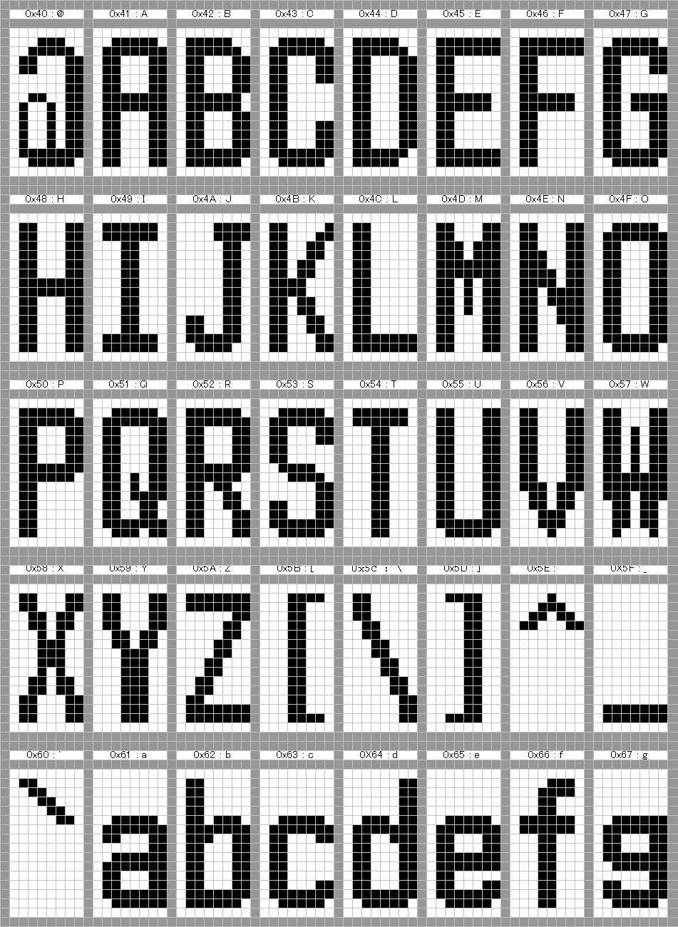
256 256

257 257

258 258
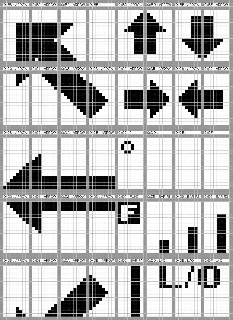
259 259
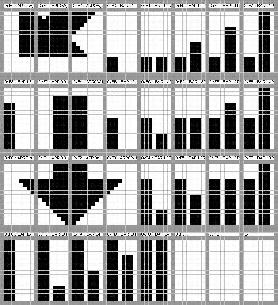
260 260

261 Character pattern of 8 x 8 dot This character pattern is Small Font. 261
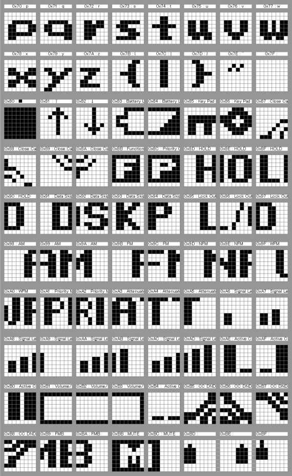
262 262
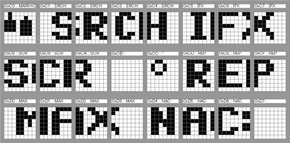
263 263
UBC3300XLT OM 5/14/04 3:28 PM Page i UBC3300XLT SCANNER
 UBC3300XLT OM 5/14/04 3:28 PM Page i UBC3300XLT SCANNER Contents Introduction...1 Front View...2 Icon Display...3 UBC3300XLT SHORTCUTS...4 Important Notice...6 Terminology...7 What is Scanning?...7 What
(stolen from the wiki NumberTags#Programming_Number_Tags )
") Introduction This is intended to be a supplementary manual for the use of the Uniden BCD396XT and BCD996XT scanners that have been introduced. Since introduction, there has been a wide observance that
Introduction This is intended to be a supplementary manual for the use of the Uniden BCD396XT and BCD996XT scanners that have been introduced. Since introduction, there has been a wide observance that
Service Search Skip...44 NWR-SAME Alert...44 Testing the Alert Siren...45 Programming FIPS Code...45 Digital and Trunked Systems...
 Contents Introduction...1 Front View...2 Icon Display...3 BC250D SHORTCUTS...4 Important Notice...6 Terminology...7 What is Scanning?...7 What is Searching?...7 What is Trunk Tracking?...7 What is APCO
UBC3500XLT OWNER S MANUAL
 UBC3500XLT OWNER S MANUAL OWNER S MANUAL Precautions Before you use this scanner, please read and observe the following. 2 EARPHONE WARNING! Be sure to use only a monaural earphone with this scanner. You
UBC126AT. Scanning Receiver. For more exciting new products please visit our website: Australia: New Zealand:
 UBC126AT Scanning Receiver For more exciting new products please visit our website: Australia: www.uniden.com.au New Zealand: www.uniden.co.nz Precautions Before you use this scanner, please read and observe
SECTION III OPERATION
 SECTION III OPERATION 3.1 INTRODUCTION This section contains information concerning the operation procedures for the BK Radio GPH Flex Mode Series handheld VHF radios. Information on installation and programming
TABLE OF CONTENTS. Keypad Programming Manual 1
 TABLE OF CONTENTS How To Program Radios...2 Keypad Programming...2 A. Navigation...3 1. Group Parameters (CH 00)...4 2. Channel Parameters (CH 01 - CH20)...4 3. Global Parameters (GRP 00)...5 B. Group
SEE QUICK START ON PAGE 3
 SEE QUICK START ON PAGE 3 Precautions Before you use this scanner, please read and observe the following. IMPORTANT! This scanning radio has been manufactured so that it will not tune to the radio frequencies
UBCT9 Scanner. 250 Channels 12 Bands Programmable Trunk Tracker lll with Close Call RF Capture
 UBCT9 Scanner 250 Channels 12 Bands Programmable Trunk Tracker lll with Close Call RF Capture Precautions Before you use this scanner, please observe the following: WARNING! Uniden does not represent this
UBC370CLT Owner s Manual
 UBC370CLT Owner s Manual Printed in Vietnam U01UB380ZZZ(0) PRECAUTIONS Before you use this scanner, please read and observe the following. IMPORTANT! Changes or modifications to this product not expressly
Precautions. Before you use this scanner, please read and observe the following.
 Precautions Before you use this scanner, please read and observe the following. IMPORTANT! This scanning radio has been manufactured so that it will not tune to the radio frequencies assigned by the FCC
UBCD396T Owner's Manual OWNER'S MANUAL. Vicradio Zone
 UBCD396T Owner's Manual OWNER'S MANUAL Precautions Before you use this scanner, please read and observe the following. EARPHONE WARNING! Be sure to use only a monaural earphone with this scanner. You can
Uniden BCD396T Firmware Revision Notes
 Uniden BCD396T Firmware Revision Notes 1.20.13 As part of Uniden s commitment to the continued support of the BCD396T, Uniden has, from time to time, issued firmware updates. These updates contain major
230-E. UB356ZH.fm Page 1 Wednesday, December 19, :28 AM UBC800XLT OWNER S MANUAL OWNER S MANUAL
 230-E UB356ZH.fm Page 1 Wednesday, December 19, 2007 11:28 AM UBC800XLT OWNER S MANUAL OWNER S MANUAL UB356ZH.fm Page 2 Wednesday, December 19, 2007 11:28 AM Precautions Before use this scanner, please
BC246T OWNER S MANUAL
 BC246T OWNER S MANUAL OWNER S MANUAL Precautions Before you use this scanner, please read and observe the following. IMPORTANT! This scanning radio has been manufactured so that it will not tune to the
BC125AT Owners Manual
 BC125AT Owners Manual 2012 Uniden America Corporation Printed in Vietnam Fort Worth, Texas U01UB370ZZZ(0) PRECAUTIONS Before you use this scanner, please read and observe the following. EARPHONE WARNING!
SC230 SC230 OWNER S MANUAL OWNER S MANUAL
 SC230 SC230 OWNER S MANUAL MANUAL OWNER S MANUAL Precautions Before you use this scanner, please read and observe the following. IMPORTANT! This scanning radio has been manufactured so that it will not
TX4400 UHF CB RADIO INSTRUCTION MANUAL TX4400 INSTRUCTION MANUAL PAGE 1
 TX4400 UHF CB RADIO INSTRUCTION MANUAL TX4400 INSTRUCTION MANUAL PAGE 1 TABLE OF CONTENTS GENERAL................................... 3 FEATURES.................................. 3 BASIC OPERATION...4 Front
I.D.A. Operation manual
 TRX-200 Wide ide Band Receiver Operation manual Thank you for purchasing the TRX-200 all modes wide band monitoring receiver. Please read this operating manual carefully to avoid miss operation of the
DJ-MD5 PC Software Guidance
 DJ-MD5 PC Software Guidance Ver, 1.00 2018/08/16 1 Appendix I Public... 4 1. Channel... 4 1 Frequency, call type, power... 4 2 Digital Channel Setting... 5 3 Analog Channel Setting... 6 2. Zone... 7 3.
Searching a Trunked Bank...39 ID Hold Mode...41 ID Lockout...42 Restore a Single ID...42 Restore all IDs...43 Searching Tips...43 Channel Activity
 CONTENTS Introduction................................... 3 Important Notice............................... 4 Terminology.................................. 5 What is Scanning?...........................
UBCD996T. Owner's Manual OWNER'S MANUAL. Vicradio Zone
 UBCD996T Owner's Manual OWNER'S MANUAL Precautions Before you use this scanner, please read and observe the following. EARPHONE WARNING! Be sure to use only a monaural earphone or 32 stereo headset. Use
SDS100E Owner's Manual
 SDS100E Owner's Manual 2018 Uniden Japan Corporation Printed in Vietnam U01UB383AZZ(0) ABOUT THIS MANUAL Radio Reference database for use in North America ONLY. NOTE Home Patrol Data Base (HPDB), ZIP Code
Owner s Manual Cat. No
 Owner s Manual Cat. No. 20-196 A PRO-2067 500-Channel Mobile Trunk-Tracking Scanner Please read before using this equipment. INTRODUCTION Your new RadioShack 500-Channel Mobile Trunk-Tracking Scanner is
TX3420 REMOTE MOUNT UHF RADIO
 TX3420 REMOTE MOUNT UHF RADIO Introduction........................... 2 Important information concerning uhf cb radio................. 2 Emergency channels.................... 3 telemetry channels.....................
Explorer 725 / 705. VHF Marine Radio Quickstart Guide.
 Explorer 725 / 705 VHF Marine Radio Quickstart Guide www.northstarnav.com This Quickstart Guide is to be used with the Northstar Explorer 721 VHF Radio Installation and Operation Manual. The Explorer 721
OPERATING GUIDE OPERATING GUIDE FOR IC-F3160/F4160 SERIES BIIS 1200/MDC 1200 SYSTEM/ LTR /IDAS NXDN OPERATION
 OPERATING GUIDE OPERATING GUIDE FOR IC-F160/F4160 SERIES BIIS 100/MDC 100 SYSTEM/ LTR /IDAS NXDN OPERATION IMPORTANT Thank you for purchasing this Icom transceiver. The BIIS 100/MDC 100 system/ltr /IDAS
OPERATING GUIDE OPERATING GUIDE FOR IC-F5060/F6060 SERIES BIIS 1200/MDC 1200 SYSTEM/ LTR /IDAS OPERATION
 OPERATING GUIDE OPERATING GUIDE FOR IC-F060/F6060 SERIES BIIS 100/MDC 100 SYSTEM/ LTR /IDAS OPERATION IMPORTANT Thank you for purchasing this Icom transceiver. The BIIS 100/MDC 100 system/ltr /IDAS (Icom
RX1300 MULTIBAND SCANNING RECEIVER INSTRUCTION MANUAL
 RX1300 MULTIBAND SCANNING RECEIVER INSTRUCTION MANUAL CAUTION Please read these instructions carefully before operating your receiver. Your scanner is a complex and powerful unit with many functions. Please
CHIPSWITCH DOC S RADIO REPAIR OWNERS MANUAL. HR2510 / HR2600 / LINCOLN 10 Meter Amateur Transceiver.
 DOC S RADIO REPAIR HR2510 / HR2600 / LINCOLN 10 Meter Amateur Transceiver CHIPSWITCH OWNERS MANUAL Revised August 28th, 2000 http://hr2510.freeservers.com/ - 1 - Table of Contents FIRST TIME INSTALL /
Special Report The Uniden-Bearcat BC396XT Digital Scanner Features, Operation and Competition
 Special Report The Uniden-Bearcat BC396XT Digital Scanner Features, Operation and Competition A Scanner Master Ultimate Review Copyright 2009, Richard Carlson/Scanner Master Corporation Introduction The
MULTIBAND SCANNING RECEIVER INSTRUCTION MANUAL
 TSC-000R MULTIBAND SCANNING RECEIVER INSTRUCTION MANUAL Manufactured by www.ttikorea.co.kr CONTENTS CAUTIONS... 5. SUPPLIED ACCESSORIES... 6. FITTING AND REMOVING THE BATTERY PACK... 6. INSTALLING THE
INSTRUCTION MANUAL. Version: /440 MHz FM DUAL BANDER TM-D710GA. 144/430 MHz FM DUAL BANDER TM-D710GE
 INSTRUCTION MANUAL 144/440 MHz FM DUAL BANDER TM-D710GA 144/430 MHz FM DUAL BANDER TM-D710GE Version: 1.01 CONTENTS OPERATING THROUGH REPEATERS...REPEATER- REPEATER ACCESS... 1 Selecting an Offset Direction...
INSTRUCTION MANUAL. Version: /440 MHz FM DUAL BANDER TM-D710GA. 144/430 MHz FM DUAL BANDER TM-D710GE
 INSTRUCTION MANUAL 144/440 MHz FM DUAL BANDER TM-D710GA 144/430 MHz FM DUAL BANDER TM-D710GE Version: 1.00 CONTENTS OPERATING THROUGH REPEATERS...REPEATER- REPEATER ACCESS... 1 Selecting an Offset Direction...
200-Channel plus 20 FM Channel VHF/Air/UHF Desktop Scanner. Please read this user's guide before installing, setting up and using your new product.
 PSR-200U 200-Channel plus 20 FM Channel VHF/Air/UHF Desktop Scanner Please read this user's guide before installing, setting up and using your new product. Owner s Manual 1 PSR200U-OM.indd 1 2010/02/22
UBC360CLT OWNER S MANUAL OWNER'S MANUAL. UB355ZH(UBC360CLT).indd /04/08 15:55:49
.indd /04/08 15:55:49") UBC360CLT OWNER S MANUAL OWNER'S MANUAL UB355ZH(UBC360CLT).indd 1 2008/04/08 15:55:49 Precautions Before you read anything else, please observe the following: Changes or modifications to this product not
UBC360CLT OWNER S MANUAL OWNER'S MANUAL UB355ZH(UBC360CLT).indd 1 2008/04/08 15:55:49 Precautions Before you read anything else, please observe the following: Changes or modifications to this product not
UBC93XLT SCANNER. 200 Channels 6 Pre-Programmed Service Banks. with Close Call RF Capture. Vicradio Zone
 UBC93XLT SCANNER 200 Channels 6 Pre-Programmed Service Banks with Close Call RF Capture For more exciting new products please visit our website: Australia: www.uniden.com.au New Zealand: www.uniden.co.nz
PROFESSIONAL DIGITAL TWO-WAY RADIO SYSTEM MOTOTRBO DP 3600/DP 3601 DISPLAY PORTABLE QUICK REFERENCE GUIDE
 PROFESSIONAL DIGITAL TWO-WAY RADIO SYSTEM MOTOTRBO DP 3600/DP 3601 DISPLAY PTABLE QUICK REFERENCE GUIDE m DP 3600/3601 Portables Quick Reference Guide Important Safety Information Product Safety and RF
RMV25 / RMV50 RMU25 / RMU45
 RMV25 / RMV50 RMU25 / RMU45 Owner's Manual TABLE OF CONTENTS INTRODUCTION... 3 FCC Requirements... 3 SAFETY WARNING INFORMATION... 3 CONTROLS and INDICATORS... 5 FRONT PANEL... 5 LCD Icons and Indicators...
OPERATING GUIDE OPERATING GUIDE FOR IC-F5060/F6060 SERIES BIIS 1200/MDC 1200 SYSTEM/ LTR /IDAS NXDN OPERATION
 OPERATING GUIDE OPERATING GUIDE FOR IC-F060/F6060 SERIES BIIS 100/MDC 100 SYSTEM/ LTR /IDAS NXDN OPERATION IMPORTANT Thank you for purchasing this Icom transceiver. The BIIS 100/MDC 100 system/ltr /IDAS
AX400 / AE 500 H First Edition Owner s Manual
 AX400 / AE 500 H First Edition Owner s Manual Thank you for purchasing our receiver For proper use of this receiver, please read this manual thoroughly. Keep this manual in a safe place for future reference.
PSR Channel VHF/Air/UHF FM/AM/WFM Handheld Scanner Owner s Manual. Page 1
 PSR-120 300 Channel VHF/Air/UHF FM/AM/WFM Handheld Scanner Owner s Manual Page 1 CONTENTS FEATURES...4 THE FCC WANTS YOU TO KNOW...5 SCANNING LEGALLY...6 PREPARATION...7 Powering The Scanner...7 Installing
BCD325P2. Owner s Manual Uniden America Corporation Printed in Vietnam U01UB379ZZZ(0)
") BCD325P2 Owner s Manual 2015 Uniden America Corporation Printed in Vietnam U01UB379ZZZ(0) EARPHONE WARNING! PRECAUTIONS Be sure to use only a monaural earphone with this scanner. You can also use an optional
BCD325P2 Owner s Manual 2015 Uniden America Corporation Printed in Vietnam U01UB379ZZZ(0) EARPHONE WARNING! PRECAUTIONS Be sure to use only a monaural earphone with this scanner. You can also use an optional
VHF 7000, 7100US, 7100EU. Operation Manual NAVMAN
 VHF 7000, 7100US, 7100EU Operation Manual w w w. n a v m a n. c o m NAVMAN FCC Statement This equipment has been tested and found to comply with the limits for a Class B digital device, pursuant to Part
BC 278CLT. Reference Guide 10 BAND, 100 CHANNEL SCANNER
 BC 278CLT 10 BAND, 100 CHANNEL SCANNER FULLY PROGRAMMABLE FULL FREQUENCY LCD READOUT ALARM CLOCK AM/FM RADIO SERVICE SCAN CHANNEL LOCKOUT PRIORITY CHANNEL SCAN DELAY MEMORY BACKUP EMERGENCY WEATHER ALERT
TABLE OF CONTENTS NOTES: Features... Inside Front Cover. FCC Requirements...4. Safety Precautions...4
 NOTES: TABLE OF CONTENTS Features... Inside Front Cover FCC Requirements...4 Safety Precautions...4 RF Energy Exposure Awareness And Control Information...5 Radio Controls...8 Basic Operation...8 Channel
REV DCA DATE DRAWN CHECKED APPROVED PUBLISHED A W /13/2014 Ken Marshall Heath Flor Jay Jensen Linda Andujo
 REVISION HISTORY Refer to the DCA and associated markups for a complete description of the changes incorporated in a revision. REV DCA DATE DRAWN CHECKED APPROVED PUBLISHED A W13295 03/13/2014 Ken Marshall
Programming Alinco -135T, 235T, and 435T VHF/UHF Radios. RADIO DISPLAYS and CONTROLS: The front panel of the radio is shown in Figure 1.
 06/01/2011 Programming Alinco -135T, 235T, and 435T VHF/UHF Radios RADIO DISPLAYS and CONTROLS: The front panel of the radio is shown in Figure 1. Figure 1 Turning The Radio On: The power switch [1] is
OPERATING GUIDE OPERATING GUIDE FOR IC-F3160/F4160 SERIES BIIS 1200/MDC 1200 SYSTEM/ LTR /IDAS OPERATION
 OPERATING GUIDE OPERATING GUIDE FOR IC-F160/F4160 SERIES BIIS 100/MDC 100 SYSTEM/ LTR /IDAS OPERATION IMPORTANT Thank you for purchasing this Icom transceiver. The BIIS 100/MDC 100 system/ltr /IDAS (Icom
YCE13. Dealer PC Programming Software Reference Manual. Attention!
 YCE13 Dealer PC Programming Software Reference Manual Attention! The YCE13 programing software can only be used with HX380/400 firmware version Ver. 2.00 or later. This software is used to program the
UBC355CLT Scanner UB367ZV_UBC355CLT_1208.indd 1 UB367ZV_UBC355CLT_1208.indd /12/08 19:55: /12/08 19:55:56
 UBC355CLT Scanner IMPORTANT INFORMATION PRECAUTIONS Before you use this scanner, please observe the following: Warning Uniden does not represent this unit to be waterproof. To reduce the risk of fire,
Field Software Notice
 To: Subject: Field Software Notice Users of 5100 ES, 51SL ES and Ascend ES Portable Radios Software Release Platform: 5100 ES Portable Protocol: All Version Release #: 6.14.5 (part number 039-5757-222)
OPERATING MANUAL Series. FM Portable Radio. Intrinsically-Safe SMARTNET, SmartZone Conventional
 7700 Series OPERATING MANUAL FM Portable Radio Intrinsically-Safe SMARTNET, SmartZone Conventional 1 LAND MOBILE PRODUCT WARRANTY - The manufacturer s warranty statement for this product is available
Reference for UV-5R Menus by Jim Unroe - KC9HI 2-April-2014
 Long Name / Description / / Notes / 0 SQL Carrier Squelch Mutes the speaker of the transceiver in the absence of a strong signal. VHF squelch is either OFF or ON. UHF squelch is either OFF or one of 9
FT-991. (WIRES-X Edition)
") HF/VHF/UHF All Mode Transceiver FT-991 Instruction Manual (WIRES-X Edition) Thank you for purchasing this Yaeau product. This instruction manual explains operations and settings associated with the WIRES-X
HF/VHF/UHF All Mode Transceiver FT-991 Instruction Manual (WIRES-X Edition) Thank you for purchasing this Yaeau product. This instruction manual explains operations and settings associated with the WIRES-X
PMR446 Radio Instruction Manual
 Tectalk PRO PMR446 Radio Instruction Manual Thank you for purchasing this radio. All our products are built to offer excellent value by combining advanced features, great design and manufacturing quality.
AT-D868UV CodePlug Programming Guide
 INTRODUCTION The AnyTone D868UV radio is a VHF and UHF radio with both Digital DMR (Tier I and II) and Analog capabilities. It offers a total of 4,000 channels (Analog and Digital), 10,000 Digital Talk
UBC72XLT SCANNER UBC72XLT OWNER S. 100 Channels 6 Pre-Programmed Service Banks. with Close Call TM RF Capture OWNER S MANUAL
 UBC72XLT SCANNER UBC72XLT OWNER S 100 Channels 6 Pre-Programmed Service Banks with Close Call TM RF Capture OWNER S MANUAL Precautions Before you use this scanner, please read and observe the following.
DC-1122 Compact 5W UHF CB Radio
 DC-1122 Compact 5W UHF CB Radio Instruction Manual Introduction! NOTE Use of the citizen band radio service is licensed in Australia by ACMA Radio communications (Citizen Band Radio Stations) Class Licence
BC92XLT OWNER S MANUAL
 BC92XLT Paper OM.fm Page 1 Tuesday, August 24, 2004 3:56 PM BC92XLT OWNER S MANUAL OWNER S MANUAL BC92XLT Paper OM.fm Page 2 Tuesday, August 24, 2004 3:56 PM Precautions Before you use this scanner, please
i410pro ADVANCED MANUAL UHF CB TRANSCEIVER INTRODUCTION 1 ACCESSORIES AND INSTALLATION 2 BASIC OPERATION 3 SET MODE 4 REPEATER OPERATION 5 SCAN
 ADVANCED MANUAL INTRODUCTION 1 ACCESSORIES AND INSTALLATION 2 BASIC OPERATION 3 SET MODE UHF CB TRANSCEIVER i410pro 4 REPEATER OPERATION 5 SCAN 6 TONE SQUELCH AND POCKET BEEP 7 SELCALL (Selective Calling)
AT-D868UV CodePlug Programming Guide
 INTRODUCTION The AnyTone D868UV radio is a VHF and UHF radio with both Digital DMR (Tier I and II) and Analog capabilities. It offers a total of 4,000 channels (Analog and Digital) and up to 130,000 contacts,
FTM-3100R/E. Advance Manual VHF FM TRANSCEIVER DIAL VOL
 FTM-3100R/E Advance Manual VHF FM TRANSCEIVER Contents Basic Operation... 3 Microphone Gain Setting... 3 RF Squelch... 3 Advanced Operation... 4 Programming the Key Assignments... 4 Tone Search... 6 DCS
DP 3600 / DP 3601 Display Portable
 Professional Digital Two-Way Radio System DP 3600 / DP 3601 Display Portable User Guide Contents This User Guide contains all the information you need to use the MOTOTRBO Series Portables. Important Safety
HM-162B/SW. z HM-162B/SW supplied accessories. x Function display INSTRUCTIONS REMOTE-CONTROL MICROPHONE
 INSTRUCTIONS REMOTE-CONTROL MICROPHONE HM-162B/SW Thank you for purchasing the HM-162B/SW REMOTE- CONTROL MICROPHONE. The COMMANDMIC III TM is a remote control microphone for use with the IC-M604 or else.
Link-5 VHF. User Guide ENGLISH. lowrance.com
 Link-5 VHF User Guide ENGLISH lowrance.com Copyright 2012 Navico All rights reserved. Lowrance is a registered trademark of Navico No part of this manual may be copied, reproduced, republished, transmitted
Explorer 710 VHF VHF Marine Radio Operation and Installation Manual
 Explorer 710 VHF VHF Marine Radio Operation and Installation Manual www.northstarnav.com IMPORTANT SAFETY INFORMATION Please read carefully before installation and use. This is the safety alert symbol.
Cat. No OWNER S MANUAL. HTX-212 Two-Meter Mobile Transceiver. Please read before using this transceiver.
 19-1125.fm Page 1 Tuesday, August 3, 1999 9:47 AM Cat. No. 19-1125 OWNER S MANUAL HTX-212 Two-Meter Mobile Transceiver Please read before using this transceiver. 19-1125.fm Page 2 Tuesday, August 3, 1999
Ray49E Marine VHF Radio Owner s Handbook. Document number: Date: June 2007
 Ray49E Marine VHF Radio Owner s Handbook Document number: 81297-1 Date: June 2007 3 Contents Trademarks and registered trademarks... 2 About this Handbook...9 Intended Use... 9 Conventions Used... 9 Technical
_ Programming Manual RE729 Including Classic and New VoX Interfaces Version 3.0 May 2011
 _ Programming Manual RE729 Including Classic and New VoX Interfaces Version 3.0 May 2011 RE729 Programming Manual to PSWx29 VoX.docx - 1 - 1 Content 1 Content... 2 2 Introduction... 2 2.1 Quick Start Instructions...
PSR Channel VHF/Air/UHF Handheld Scanner. Owner s Manual. Add photograph
 PSR-282 200-Channel VHF/Air/UHF Handheld Scanner Owner s Manual Add photograph 1 INTRODUCTION Your new 200 Channel VHF/Air/UHF Handheld Scanner lets you scan conventional transmissions, and is preprogrammed
PRO Channel Desktop Trunk-Tracking Scanner
 PRO-2053 300 Channel Desktop Trunk-Tracking Scanner Owner s Manual Please read before using this equipment. ˆ The FCC Wants You to Know This equipment has been tested and found to comply with the limits
OPERATING GUIDE VHF DIGITAL TRANSCEIVERS. if1000d. series UHF DIGITAL TRANSCEIVERS. if2000d series. The photo shows the VHF transceiver.
 OPERATING GUIDE VHF DIGITAL TRANSCEIVERS if1000d UHF DIGITAL TRANSCEIVERS series if2000d series The photo shows the VHF transceiver. TABLE OF CONTENTS 1. PANEL DESCRIPTION Front, top and side panels 1-2
Content. Maintenance. Features ENGLISH. 1 transceiver 1 antenna 1 battery pack 1 belt clip 1 fast desktop charger User manual
 ENGLISH Content 1 transceiver 1 antenna 1 battery pack 1 belt clip 1 fast desktop charger User manual If any items are missing, contact your dealer. Maintenance Your Two Way Radio is an electronic product
Pair of PMR446 Two-Way Personal Radios Model: TP391
 Pair of PMR446 Two-Way Personal Radios Model: TP391 USER MANUAL MANUALE D USO MANUEL DE L UTILISATEUR BEDIENUNGSANLEITUNG MANUAL DE USUARIO MANUAL DO USUÁRIO HANDLEIDING BRUKSANVISNING P/N:086L004722-016
UM455 VHF DSC Marine Radio
 UM455 VHF DSC Marine Radio For more exciting new products please visit our website: Australia: www.uniden.com.au Making a distress call NOTE: There is no official VHF DSC shore infrastructure in Australia.
20-524A.fm Page 1 Tuesday, June 27, :41 PM. Owner s Manual. PRO Channel Handheld Trunking Scanner
 20-524A.fm Page 1 Tuesday, June 27, 2000 3:41 PM Owner s Manual PRO-94 1000-Channel Handheld Trunking Scanner Please read before using this equipment. 20-524A.fm Page 2 Tuesday, June 27, 2000 3:41 PM ˆ
BC 248CLT. Reference Guide 10 BAND, 50 CHANNEL SCANNER
 BC 248CLT 10 BAND, 50 CHANNEL SCANNER FULLY PROGRAMMABLE FULL FREQUENCY LCD READOUT ALARM CLOCK AM/FM RADIO ONE TOUCH WEATHER CHANNEL LOCKOUT PRIORITY CHANNEL SCAN DELAY MEMORY BACKUP EMERGENCY WEATHER
AT-D868UV CodePlug Programming Guide
 INTRODUCTION The AnyTone D868UV radio is a VHF and UHF radio with both Digital DMR (Tier I and II) and Analog capabilities. It offers a total of 4,000 channels (Analog and Digital), 10,000 Digital Talk
S! Applications & Widgets
 S! Appli...-2 Using S! Applications... -2 Mobile Widget... -3 Customizing Standby Display (Japanese)... -3 Additional Functions... -6 Troubleshooting... - S! Applications & Widgets -1 S! Appli Using S!
PSR-295. Portable Scanner OWNER S MANUAL
 PSR-295 Portable Scanner OWNER S MANUAL 1 Contents FEATURES... 3 PREPARATION... 5 Power Sources... 5 Connecting the Supplied Antenna... 8 Connecting an Earphone/Headphones... 8 Connecting an Extension
DUAL BAND MOBILE RADIO USER S MANUAL
 DUAL BAND MOBILE RADIO USER S MANUAL Thank you for your purchase of the product. This dual band radio will deliver to you secure instant reliable communication. Please read this manual carefully before
Easy Operation Instructions
 Easy Operation Instructions I. Panel Description 1 PWR DAIL : Power Switch PWR /Volume Adjustment VOL /Frequency Adjustment/ MENU Key/Enter Key etc. Operation: Power Switch PWR : To switch the transceiver
FEATURE FUNCTION BENEFIT. The IC-F1721D/F1821D series comes in 2 styles: the simple version and the 10-key version
 P25 ICOM F1721D/F1821D SERIES YOUR ANALOG TO DIGITAL CONVERSION GENERAL Two Versions Rugged Construction The IC-F1721D/F1821D series comes in 2 styles: the simple version and the 10-key version Heavy "heat
Important safety instructions
 RCR-29 GB Version 1 Important safety instructions VERY IMPORTANT PLEASE READ Sangean suggest that you keep your AC Adapter at least 12 inches away from the radio while listening to the AM Band. Your Sangean
VHF 110/210 AIS Series. Owner s Manual
 VHF 110/210 AIS Series Owner s Manual 2017 Garmin Ltd. or its subsidiaries All rights reserved. Under the copyright laws, this manual may not be copied, in whole or in part, without the written consent
VHF585 CLASS D MARINE RADIO MODEL (BLACK) / (WHITE) Owner s Manual
 / (WHITE) Owner s Manual") VHF585 CLASS D MARINE RADIO MODEL 16230534 (BLACK) / 16230542 (WHITE) Owner s Manual MAKING A DISTRESS CALL Lift the red cover. Press and hold the DISTRESS button for three seconds. Your radio transmits
VHF585 CLASS D MARINE RADIO MODEL 16230534 (BLACK) / 16230542 (WHITE) Owner s Manual MAKING A DISTRESS CALL Lift the red cover. Press and hold the DISTRESS button for three seconds. Your radio transmits
FT-70DR FT-70DE. Advance Manual. C4FM/FM 144/430MHz DIGITAL/ANALOG TRANSCEIVER
 C4FM/FM 144/430MHz DIGITAL/ANALOG TRANSCEIVER FT-70DR FT-70DE Advance Manual Clicking (tapping) at the at the bottom left of the current browsing page, will return to the contents page at any time. Contents
PSR Channel VHF/Air/UHF Handheld Scanner. Owner s Manual
 PSR-100 200 Channel VHF/Air/UHF Handheld Scanner Owner s Manual 1 CONTENTS Features... 4 Preparation... 6 Power Sources... 6 Using Batteries... 6 Charging Rechargeable Batteries... 8 Using AC Power...
PSR ,000 Channel Triple Trunking Hand Held Scanner. Owner s Manual
 PSR-300 1,000 Channel Triple Trunking Hand Held Scanner Please read this user s guide before installing, setting up and using your new product. Owner s Manual 1 CONTENTS FEATURES... 4 PREPARATION... 7
GX600D VHF MARINE RADIO INSTRUCTION MANUAL PRINTED IN ENGLISH INTERNATIONAL: 0168! USA : FCC ID : TXJGX600D CANADA : IC 7332A-GX600D AUSTRALIA:
 GX600D VHF MARINE RADIO INSTRUCTION MANUAL PRINTED IN ENGLISH INTERNATIONAL: 0168! USA : FCC ID : TXJGX600D CANADA : IC 7332A-GX600D AUSTRALIA: WARNING: SAFETY INFORMATION The GX600D is a radio transmitting
Commercial Series CM160
 Commercial Series CM160 User Guide 6866545D04 - O Issue: October 2003 3 1 5 6 2 CHAN 34 P1 P2 P3 P4 7 4 10 10 11 11 8 9 CONTENTS RadioOverview... 3 Radio Controls...................... 3 Microphone Controls.................
FT-991. (WIRES-X Edition)
") HF/VHF/UHF All Mode Transceiver FT-991 Instruction Manual (WIRES-X Edition) Thank you for purchasing this Yaeau product. This instruction manual explains operations and settings associated with the WIRES-X
HF/VHF/UHF All Mode Transceiver FT-991 Instruction Manual (WIRES-X Edition) Thank you for purchasing this Yaeau product. This instruction manual explains operations and settings associated with the WIRES-X
INSTALLATION AND OPERATION GUIDE
 VHF Marine Radio RT-311 INSTALLATION AND OPERATION GUIDE Navicom plaisance: Z.A. des Boutries, 78700 Conflans Ste Honorine Tel: 01.39.72.19.90 Fax: 01.39.19.28.98 Navicom Pro: 3, rue J. Cugnot, Z.A.C Petit
WIRES-X Portable Digital Node Function. Instruction Manual
 Wide-Coverage Internet Repeater Enhancement System WIRES-X Portable Digital Node Function Instruction Manual Please read this Instruction Manual carefully for appropriate procedure. Preparation Procedure
i2820h (USA) ie2820(europe)
 ie2820(europe)") January 2007 DUAL BAND TRANSCEIVERS i2820h (USA) ie2820(europe) The above photo shows the IC-2820H. The IC-E2820 differs slightly from this photo. Icom proudly announces the debut of the new dual band
January 2007 DUAL BAND TRANSCEIVERS i2820h (USA) ie2820(europe) The above photo shows the IC-2820H. The IC-E2820 differs slightly from this photo. Icom proudly announces the debut of the new dual band
PRO Channel compact scanner w/signal stalker search and lighted keypad. Read this user s guide completely before using your scanner
 20-501.fm Page 1 Friday, July 9, 2004 3:23 PM 20-501 PRO-83 200 Channel compact scanner w/signal stalker search and lighted keypad Read this user s guide completely before using your scanner 20-501.fm
VHF 110/210 AIS Series. Owner s Manual
 VHF 110/210 AIS Series Owner s Manual Table of Contents Introduction...1 Radio Overview... 1 Handset Overview... 1 Home Screen... 1 System Status Icons... 1 Basic Operation... 2 Turning On and Off the
VHF 115/215 AIS SERIES. Owner s Manual
 VHF 115/215 AIS SERIES Owner s Manual 2018 Garmin Ltd. or its subsidiaries All rights reserved. Under the copyright laws, this manual may not be copied, in whole or in part, without the written consent
AR-ONE. Ultra Wide Band Communications Receiver. Operating manual v.2.1 AOR, LTD.
 AR-ONE Ultra Wide Band Communications Receiver Operating manual v.2.1 AOR, LTD. March 1, 2010 Table of contents 1 Introduction ------------------------------------------------------------------------------------------------