R&S FSL Spectrum Analyzer High-end functions in an extremely lightweight, compact package
|
|
|
- Gavin Anderson
- 6 years ago
- Views:
Transcription


1 R&S FSL Spectrum Analyzer High-end functions in an extremely lightweight, compact package Test & Measurement Product Brochure 07.00

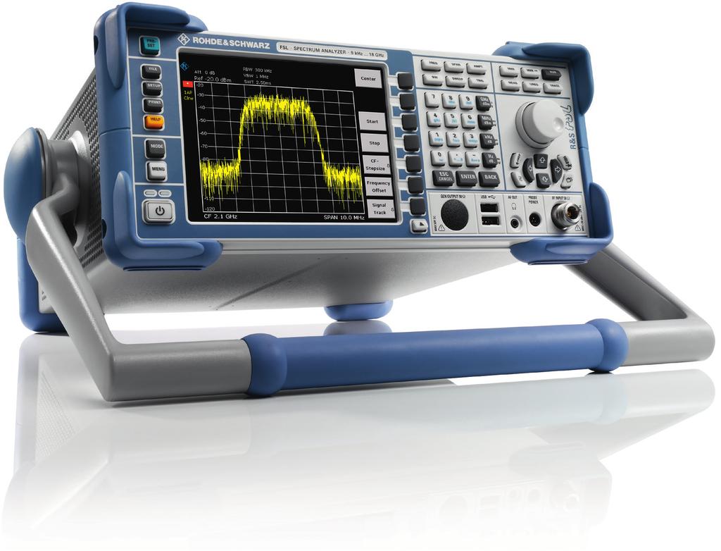
2 R&S FSL Spectrum Analyzer At a glance You no longer have to make comprises when buying a spectrum analyzer. You can now get high-end features without stretching your budget the R&S FSL. The R&S FSL is an extremely lightweight and compact spectrum analyzer that is ideal for a large number of applications in development, service and production. Despite its compact size, it offers a wealth of functions more typical of the high-end range, thus ensuring an excellent price/performance ratio. The R&S FSL is the only instrument in its class that features a tracking generator up to 18 GHz and can analyze signals with a bandwidth of 28 MHz. In addition, the R&S FSL18, which operates at frequencies up to 18 GHz, supports applications in the microwave range. The high-end approach is also evident in the operating features. When equipped with a tracking generator up to 18 GHz, the R&S FSL18 is an easily portable, microwave scalar network analyzer. As with the higher-class analyzers from Rohde & Schwarz, the main functions of the R&S FSL are directly accessible by fixed-assignment function keys, with additional functions accessed using softkeys and tables. This shortens the learning curve for new users. Its compact size and low weight, plus its optional battery pack, make the R&S FSL ideal for mobile use. The R&S FSL has unique plug & play upgrade abilities. All options can be added without opening the instrument. Main features Frequency range 9 khz to 3 GHz/6 GHz/18 GHz 3 GHz, 6 GHz and 18 GHz models with and without tracking generator Best RF characteristics in its class Largest signal analysis bandwidth in its class (28 MHz) Low measurement uncertainty, even in microwave range High resolution filter accuracy owing to all-digital implementation Robust and compact Carrying handle and low weight (<8 kg/18 lbs) Optional battery operation Wide range of functions, simple operation Easy on-site upgrading with options The R&S FSL is a full-featured analyzer with the widest demodulation bandwidth and the best RF characteristics in its class. 2
3 R&S FSL Spectrum Analyzer Benefits and key features Exceptional performance for its class Continuous RF frequency range from 9 khz to 18 GHz and 28 MHz demodulation bandwidth Low measurement uncertainty even in microwave range page 4 Fast and versatile in production High measurement speed and time-saving routines improve throughput Remote control via LAN or IEC/IEEE bus in line with SCPI page 5 At home in every development lab Excellent price/performance ratio General-purpose signal analysis Wide range of personalities for various wireless/cellular digital standards page 6 Lightweight and compact for on-site installation, maintenance and service Easy portability due to small size and low weight Optional internal battery pack for cordless use Power measurements with R&S NRP-Zxx power sensors page 7 Easy upgrades and a wide range of interfaces On-site plug & play installation of options without opening the instrument Additional interfaces expand the application range of the R&S FSL page 8 Wide range of functions simple operation Comprehensive set of measurement functions and features more typical of high-end analyzers Built-in measurement routines and versatile selection of firmware options page 9 Rohde & Schwarz R&S FSL Spectrum Analyzer 3
 of typ. 162 dbm, the R&S FSL compares favorably with high-end analyzers.")
4 Exceptional performance for its class With phase noise of typ. 103 dbc (1 Hz) at 10 khz from the carrier, a third order intercept point of typ. +18 dbm, a bandwidth range from 10 Hz to 10 MHz, and a displayed average noise level (DANL) of typ. 162 dbm, the R&S FSL compares favorably with high-end analyzers. This makes it very useful in production, service, field use and in labs. The RF attenuator, which is adjustable in steps of 5 db, and the optional preamplifier ensure an optimum usable dynamic range. Continuous RF frequency range from 9 khz to 18 GHz and 28 MHz demodulation bandwidth The R&S FSL is the only instrument in its class with a bandwidth of 28 MHz. Featuring an analysis bandwidth of 28 MHz, the spectrum analyzer is ideal for measuring both spectral and modulation parameters of broadband signals such as WLAN and WiMAX, including harmonic signals up to 18 GHz. In the time domain, its fast digitizer allows the detection of pulsed signals and the measurement of pulse widths. There are six different R&S FSL models available (see page 21 for specifications): R&S FSL3: 9 khz to 3 GHz (available with and without tracking generator) R&S FSL6: 9 khz to 6 GHz (available with and without tracking generator) R&S FSL18: 9 khz to 18 GHz (20 GHz overrange, available with and without tracking generator) The R&S FSL18 covers frequencies up to 18 GHz, which makes it ideal for a large number of development, service and production applications at microwave frequencies. Examples include the installation and maintenance of radar systems and microwave links, as well as the production of microwave components or satellite surveillance. Typical applications of the R&S FSL18 include measurements in the microwave range, for example measuring the pulse width using the n-db down marker. Low measurement uncertainty Another unrivaled characteristic in its class is the low overall measurement uncertainty, which yields accurate and reliable results even in the microwave range. The analyzer's low measurement uncertainty makes tests and alignment more accurate and reliable and allows a separate power meter to be replaced. Moreover, it reduces the margin needed for test instrument uncertainty and thus increases the margin left for the DUT. 4


5 Fast and versatile in production The R&S FSL is ideal for fast, easy measurements during production. A quick check of the level and frequency is often all that s needed. The R&S FSL s high speed of >80 sweeps/s in zero span, including remote output of data (or trace data), ensures high production throughput. Even a simple level calibration can be streamlined and accelerated with the R&S FSL s integrated complex measurement functions a special multisum mary marker measures different levels in the time domain in a single sweep. This eliminates reset and remote control overhead time. For fast synchronization or triggering, the R&S FSL-B5 additional interfaces option which includes a special trigger interface can be added. In addition, the R&S FSL offers the following functions: Fast ACP measurements in the time domain for the major wireless communications standards, with very good repeatability and short measurement times List mode: measurements with up to 300 analyzer settings with a single IEC/IEEE bus command Fast power measurement in the time domain using channel or RRC filters Fast frequency counter with 1 Hz resolution and measurement times <50 ms Remote control via LAN or IEC/IEEE bus in line with SCPI The standard remote interface is a 10/100BaseT LAN interface that provides significantly higher speeds than an IEC/IEEE bus for transferring large data volumes. It also offers considerable cost advantages over IEC/IEEE bus wiring. However, IEC/IEEE bus remote control can be added by installing the R&S FSL-B10 option. The command set of the R&S FSL follows SCPI conventions and is thus largely compatible with the R&S FSP and R&S FSU analyzers. Remote control of the R&S FSL via IEC/IEEE bus in list mode cuts down on measurement time. Input command SENSE:LIST:POW 100MHz,-0dBm,10dB,10dB,NORM,1MHz,3MHz,434us,0, 200MHz,-20dBm,10dB,0dB,NORM,30kHz,100kHz,1ms,0, 300MHz,-20dBm,10dB,0dB,NORM,30kHz,100kHz,1ms,0; Output FSL -28.3, -30.6, Rohde & Schwarz R&S FSL Spectrum Analyzer 5


6 At home in every development lab The R&S FSL s excellent price/performance ratio makes it a must for every developer s lab bench, as indispensable as an oscilloscope or multimeter. Its range of functions and operation are largely identical with those of the R&S FSU high-end analyzers, simplifying the reproducible verification of measurements. Good RF performance at a low price Widest I/Q demodulation bandwidth in its class Quasi-peak detectors and EMC bandwidths of 200 Hz, 9 khz and 120 khz for EMC checks during development and precompliance testing Tracking generator for transmission and reflection measurements (e.g. with the R&S ZRB2 or R&S FSH-Z2 VSWR bridge) High measurement accuracy Easy output of measurement results to USB printer, network printer or file Easy remote control via LAN Connection to MATLAB The R&S FSL s wide scope of functions also extends to channel/adjacent channel power measurements. To simplify use, many default settings can be selected by pressing a button. The R&S FSL offers many different firmware options (see page 22). The user can switch between the different applications. 6

7 Lightweight and compact for on site installation, maintenance and service The low weight (<8 kg), the small size and the ruggedized housing make the R&S FSL ideal for mobile applications. Due to these properties it is easy to carry to remote or hard-to-reach locations. The carrying bag with space for an extra battery pack and accessories and the protective hardcover are also very convenient for field use. Optional internal battery pack for cordless use When equipped with the optional internal battery pack (R&S FSL-B31), the R&S FSL can be used independent of the mains supply for at least one hour. Easy and fast battery exchange in the field increases battery operation time. In addition, a DC power supply (R&S FSL-B30) is available for the R&S FSL. This option allows the R&S FSL to be used anywhere where DC power is available, e.g. in a car. Power measurements with R&S NRP-Zxx power sensors Another special feature of the R&S FSL is the fact that you can directly connect a power sensor from the R&S NRP-Z series. The R&S FSL-K9 option and a connected power sensor allow very precise measurements of the DUT power an enormous advantage for applications where level accuracy is crucial. The R&S FSL can thus replace a power meter. This is particularly important in mobile applications. Ideal for service Cost-effectiveness High measurement accuracy Extensive evaluation options Wide range of functions Built-in frequency counter AM/FM audio demodulator for interference identification Extensive functions for power measurements Storage of settings and measurement results in the R&S FSL or on a USB memory stick Soft carrying bag for the R&S FSL. Rohde & Schwarz R&S FSL Spectrum Analyzer 7

8 Easy upgrades and a wide range of interfaces The R&S FSL has unique plug & play upgrade abilities. All options can be added without opening the instrument. This has several important advantages: No extra alignment after installation No recalibration No need to send in the instrument, thus negligible downtime No installation costs Easy installation of additional functions The wide range of additional inter faces provided by the R&S FSL-B5 option expands the application range of the R&S FSL: IF output/video output for connecting further instruments 28 V, switchable for connecting noise sources Trigger interface for fast measurement on frequency lists Connector for an R&S NRP-Zxx power sensor (replaces the USB adapter for the R&S NRP-Zxx power sensors) Battery pack (R&S FSL-B31) Additional interfaces OCXO (R&S FSL-B4, (R&S FSL-B5) standard in the R&S FSL18) IEC/IEEE (GPIB) bus interface (R&S FSL-B10) DC power supply (R&S FSL-B30) 8
9 Wide range of functions simple operation The R&S FSL offers a comprehensive set of measurement functions and features that are more typical of high-end analyzers. A versatile selection of firmware options helps save costs as a low-budget spectrum analyzer can be used whenever the specifications of a high-end spectrum analyzer are not required. An intuitive user interface supports users with measurements in line with standards. In addition, preconfigured, built-in measurement routines help the user to quickly get results. Measurement routines for: Third order intercept measurement (TOI) Occupied bandwidth measurement (OBW) Time domain power measurement Channel power measurement (CP) Adjacent channel power and multicarrier adjacent channel power measurement (ACP and MC-ACP) Fast adjacent channel power measurement (ACP) Carrier-to-noise ratio measurement (C/N, C/N 0 ) Modulation depth measurement (AM%) Application firmware for general-purpose signal analysis AM/FM/φM measurement demodulator (R&S FSL-K7 option, page 14) Power measurement with R&S NRP-Zxx power sensors (R&S FSL-K9 option) Spectrogram measurements (R&S FSL-K14 option, page 13) Cable TV measurements (R&S FSL-K20 option, page 16) Noise figure and gain measurement (R&S FSL-K30 option, page 17) TV trigger (R&S FSL-B6 option, page 11) Gated sweep (R&S FSL-B8 option, page 11) Standard features 28 MHz I/Q demodulation bandwidth Complete range of detectors RRC and channel filters FFT filters 1 Hz/300 Hz to 30 khz Frequency counter Noise and phase noise markers n-db down marker Limit lines Level units Selectable number of trace points Transducer factors LAN interface USB Help function Application firmware for varios wireless/cellular standards Bluetooth modulation and spectrum measurements (R&S FSL-K8 option, page 15) WCDMA (R&S FSL-K72 option) CDMA2000 /1xEV-DO modulation and spectrum measurement (R&S FSL-K82/-K84 options, page 18) WLAN transmitter measurements (R&S FSL-K91/-K91n options, page 19) WiMAX modulation and spectrum measurements (R&S FSL-K92/-K93 options) Rohde & Schwarz R&S FSL Spectrum Analyzer 9


10 Scalar network analysis Models.13,.16 and.28 of the R&S FSL, which include a tracking generator, can quickly and easily measure frequency response, filters and attenuation. The n-db down marker determines the 3 db bandwidth of a bandpass filter at the press of a button, for example. The R&S FSL measures return loss or matching by using an external VSWR bridge. Precision is enhanced by Through, Short and Open normalization methods. Third order intercept (TOI) The R&S FSL can determine the TOI from the spectrum at the press of a button. It automatically detects the useful carriers and thus determines the intermodulation sidebands. The instrument s maximum dynamic range of 95 db is high for its class. RF attenuation steps of 5 db further enhance its usefulness. Modulation depth measurement (AM%) The R&S FSL measures the modulation depth of an AM signal at the press of a button. The AM% marker function positions three markers one each on the carrier, the upper sideband and the lower sideband and uses the sideband suppression to determine the modulation depth. The modulation depth of a two-tone signal can be determined selectively by predefining the modulation frequency, for example by starting with a 90 Hz sideband and then moving to the 150 Hz sideband of an ILS signal. The high linearity of <0.2 db ensures a small absolute measurement error. 10


.")
11 Spurious emissions measurements Spurious emissions measurements very often require different measurement bandwidths for different frequency ranges. They can easily be performed by using the spurious emissions functions in the sweep list table, which allows to set parameters such as RBW, VBW, detector, level, number of sweep points individually for different frequency ranges. This makes a complete spurious emissions measurement very fast and easy as setup and measurement is made only once and not separately for each frequency range. A segmented sweep can also easily be set up using this function. Gated sweep The R&S FSL uses the gated sweep function (R&S FSL-B8 option) for burst signal measurements. This function can display the modulation spectrum of a GSM signal or a burst WLAN signal (as shown in the example). TV trigger option The R&S FSL-B6 TV trigger generates a trigger in response to selectable lines and the horizontal or vertical blanking interval. Video formats with 525 or 625 lines with positive or negative modulation are covered. Rohde & Schwarz R&S FSL Spectrum Analyzer 11

 measurements, for example cdmaone The ACP measurement function determines the adjacent channel power as an absolute value or relative to the useful")

12 Channel power measurements Channel power measurements use integration to determine the power within a defined channel bandwidth. The full- featured RMS detector is used to measure the correct power independent of the signal, which ensures good repeatability and accuracy. The channel width can be defined by the user or selected from an extensive list of transmission standards. Adjacent channel power (ACP, MC-ACP) measurements, for example cdmaone The ACP measurement function determines the adjacent channel power as an absolute value or relative to the useful carrier. The R&S FSL offers predefined settings for many transmission standards, but parameters can also be user-defined, with channel widths and spacings for up 12 channels and up to 12 adjacent channels. Fast ACP in time domain with standard-compliant channel filters The fast ACP function measures the adjacent channel power in the time domain using standard-compliant channel filters. This reduces the measurement time necessary for a specific repeatability by a factor of 10. It also provides an easy way to determine transient, time-dependent adjacent channel power. 12


13 Burst power measurement: time domain power This feature allows the burst power to be measured in the time domain. Display lines delimit the evaluation area, thus making it possible to determine the power during the 147 useful bits of a GSM burst, for example. Occupied bandwidth (OBW) OBW is a measure of the bandwidth occupied by the signal. The R&S FSL determines the bandwidth containing, for example, 99 % of the signal power from the total power within the span. The points from the right and left edge of the trace are summed up until 1 % of the power is reached. The remaining power then corresponds to 99 % of the power and the distance between the two frequency markers is the occupied bandwidth, which is displayed in the marker field. The fully synchronous frequency sweep and the high number of trace points make this measurement very precise. Spectrogram measurements The R&S FSL-K14 option adds a spectrogram display and trace recording to the R&S FSL. The spectrogram view shows a history of the spectrum and helps to analyze intermittent problems or variations in frequency and level versus time. It also adds a new trigger, i.e. a time trigger that makes it possible to record a trace at a regular time interval. Recording of up to traces: approx. 5.5 h continuous monitoring with repetition interval set at 1 s Time trigger, repetition interval 100 ms to 5000 s: allows unattended continuous monitoring Scrolling through recorded traces with markers: replay and repeatedly analyze the recorded data Rohde & Schwarz R&S FSL Spectrum Analyzer 13

14 R&S FSL-K7 option AM/FM/φM measurement demodulator The R&S FSL-K7 AM/FM/φM measurement demodulator converts the R&S FSL into an analog modulation analyzer for amplitude-, frequency- or phase- modulated signals. It measures not only characteristics of the useful modulation, but also factors such as residual FM or synchronous modulation. Display and evaluation capabilities Modulation signal versus time Spectrum of modulation signal (FFT) RF signal power versus time Spectrum of RF signal (FFT versus max. 18 MHz) Table with numeric display of Deviation or modulation depth, +Peak, Peak, ± Peak/2 and RMS weighted Modulation frequency Carrier frequency offset Carrier power Total harmonic distortion (THD) and SINAD Condensed data Demodulation bandwidth 100 Hz to 18 MHz Recording time (depends on 12.5 ms to 3276 s demodulation bandwidth) AF filters Highpass filter 50 Hz, 300 Hz Lowpass filter 3 khz, 15 khz, 150 khz and 5 %, 10 % or 25 % of demodulation bandwidth Deemphasis 25/50/75/750 µs Modulation frequency < 5 MHz, max. 0.5 demodulation bandwidth Measurement uncertainty 3 % (deviation or modulation depth) THD measurement on an amplitude-modulated signal: The first harmonic of the modulation signal is well suppressed by 69 db. This corresponds to a THD (D2) of less than 0.1 %. Frequency deviation measurement: display of modulation signal together with peak and RMS deviation, carrier frequency offset and carrier power. 14


 Differential phase encoding Relative transmit power: The EDR relative")
15 R&S FSL-K8 option Transmitter measurements for Bluetooth V2.0 and EDR The R&S FSL-K8 application firmware enhances the range of applications of the R&S FSL spectrum analyzer to include measurements on Bluetooth transmitters. All measurements are carried out in line with the Bluetooth RF Test Specification (Bluetooth SIG) Rev. 2.0+EDR and cover basic rate as well as EDR. Integrated limit value monitoring is provided for all measurements and allows analysis of the results in the development and production of Bluetooth modules. Bluetooth measurements Basic rate measurements Output power ACP over up to 79 channels Modulation characteristics Initial carrier frequency tolerance Carrier frequency drift EDR measurements Output power and relative transmit power Inband spurious emissions, gated Carrier frequency stability and modulation accuracy (DEVM) Differential phase encoding Relative transmit power: The EDR relative transmit power determines the power of the GFSK-modulated and the DPSK-modulated part and the power difference. Adjacent channel power (ACP): This measurement determines the power of all adjacent channels. The power of up to 79 channels in total can be measured. For EDR inband spurious, the measurement can be gated. Modulation characteristics: This measurement determines the maximum frequency deviation of all 8-bit test sequences of the payload. In addition, the average value of the maximum frequency deviations per packet is calculated and displayed. Rohde & Schwarz R&S FSL Spectrum Analyzer 15

 and CSO (composite second order), off-service or during quiet line Vision modulation Hum Video scope function for detailed line analysis Tilt: determines the frequency")

16 R&S FSL-K20 option Analog and digital cable TV measurements The R&S FSL-K20 CATV option provides easy-to-use push- button measurements for analog and digital cable TV networks as well as for analog TV transmitters. TV standards Selectable analog TV standards B/G, D/K, I, K1, L, M, N PAL, NTSC, SECAM Measurements Analog TV Carrier levels (picture and sound carriers) C/N (in-service, off-service, quiet line) CTB (composite triple beat) and CSO (composite second order), off-service or during quiet line Vision modulation Hum Video scope function for detailed line analysis Tilt: determines the frequency response of the cable TV network by measuring the channel power of every channel Selectable digital cable TV standards QAM J.83/A (EU), J.83/B (US), J.83/C (Japan) 4QAM to 1024QAM Symbol rate: 0.1 Msymbol/s to 7.15 Msymbol/s Digital TV Channel power Modulation parameters and errors: carrier frequency offset, symbol frequency offset, MER, EVM, phase jitter, carrier suppression, quadrature offset, imbalance Constellation diagram Echo pattern Signal statistics/ccdf, APD Channel tables Channel tables make it possible to preconfigure the R&S FSL for a specific network: Channel numbers can be assigned to frequencies The signal type for each channel can be defined (analog TV signal, digital TV signal) as well as even more detailed properties such as the position of test lines The R&S FSL is set up correctly just by entering the channel number. Channel tables can be easily copied and multiplied between different instruments. Video scope function (video line analysis) and vision modulation A dedicated video line trigger allows selected lines of the video signals to be displayed for detailed analysis. The vision modulation measurement further determines the modulation depth and residual picture carrier level. Digital TV signals A table provides a quick overview of the most important modulation quality parameters such as MER, EVM (both peak and RMS), carrier frequency offset and symbol frequency offset. Typical I/Q modulator impairments such as quadrature offset or gain imbalance can be evaluated from the modulation error table (see picture). A constellation diagram enables further analysis of faults and their cause. 16
.")

. Noise measurements Measurement range 0 db to 35 db Resolution 0.01 db Measurement accuracy ±0.")
17 R&S FSL-K30 option Noise figure and gain measurements The R&S FSL-K30 application firmware provides the R&S FSL spectrum analyzer with features otherwise only provided by special noise measurement analyzers. Test setup (schematics). The following parameters can be measured at a specified frequency or in a selectable frequency range: Noise figure in db Noise temperature in K Gain in db Compared with conventional noise measurement systems, R&S FSL-K30 has the advantage that a wide variety of further RF measurements can also be performed. The R&S FSL also allows the measurement of harmonics, intermodulation, spurious responses and many other RFrelevant criteria (for measurements on amplifiers and on frequency-converting DUTs, e.g. low-noise converters). Noise measurements Measurement range 0 db to 35 db Resolution 0.01 db Measurement accuracy ±0.3 db (measurement with external preamplifier (gain 30 db, noise figure <5 db) and 1 MHz resolution bandwidth, valid for DUTs with noise figure 1 db to 10 db and gain >10 db) Gain measurements Measurement range 0 db to 60 db Resolution 0.01 db Measurement accuracy ±0.2 db (measurement with preamplifier (gain 30 db, noise figure <5 db) and 1 MHz resolution bandwidth) Required hardware R&S FSL-B5 noise source power supply (via 28 V connector on the R&S FSL rear panel) Noise source, e.g. NoiseCom NC346 External preamplifier (for improved accuracy and repeatability of measurements) Tabular representation of measurement results. Measurements on an amplifier. Rohde & Schwarz R&S FSL Spectrum Analyzer 17


18 R&S FSL-K82/-K84 options CDMA2000 / 1xEV-DO transmitter measurements The R&S FSL-K82 application firmware enhances the application range of the R&S FSL spectrum analyzer to include code domain power and modulation measurements on CDMA2000 signals for radio configurations 1 to 5 and 10. The R&S FSL-K84 application firmware adds capability for the analysis of 1xEV-DO signals. The R&S FSL is the ideal tool for CDMA2000 base station transmitter measurements in service and production. The main application is the determination of the power in the individual code channels referred to as code domain power measurement. The power ratios between the individual channels, for example, can be checked for compliance with the nominal values. Moreover, this measurement is a very efficient tool for detecting transmitter impairments such as clipping or intermodulation that are not obvious from the spectrum alone. Equipped with the R&S FSL-K82/-K84, the R&S FSL provides the functionality needed for base station testing as well as the related parameters: Code domain power (code domain analyzer) Code domain power versus time (R&S FSL-K82) Power versus chip (R&S FSL-K84) Rho Error vector magnitude (EVM) Peak code domain error Power versus symbol Symbol constellation Channel table Code domain error power For 1xEV-DO, the rho measurement is subdivided into several new measurements due to the time division structure: Rho MAC Rho data Rho pilot Rho overall-1 Rho overall-2 The code domain power measurement displays the active and inactive channels in bit-reversed order. The result summary provides a quick overview of the main parameters of the signal at a glance, e.g. total power, channel power, rho and EVM. The upper part of the screen shows an overview of the detected channels and a number of parameters such as power and timing offset. The lower part shows the composite constellation diagram of the signal. 18


19 R&S FSL-K91/-K91n options WLAN transmitter measurements The R&S FSL-K91 WLAN application firmware expands the application range of the R&S FSL spectrum analyzer by spectrum and modulation measurements on signals in line with the WLAN IEEE a/b/g/j standards. The R&S FSL-K91n application firmware adds capability to analyze 20 MHz signals in line with IEEE n. The excellent price/performance ratio, the compact size and the capability to be remote-controlled make the R&S FSL an ideal WLAN tester in production. The R&S FSL s analysis and evaluation capabilities, which enable measurements beyond the scope of the standard, make it indispensable for applications in development and troubleshooting. Functions, operation and remote control commands are essentially identical to those of the R&S FSQ signal and spectrum analyzer with the R&S FSQ-K91/-K91n option. Measurement Output power Spectrum mask with limit lines and pass/fail indication Adjacent channel power Burst rise and fall times EVM EVM versus carrier or time Constellation diagram (for specific or all carriers) Constellation overview Selectable tracking: phase, level, timing RF carrier leakage Carrier frequency and symbol clock error CCDF and crest factor Bit stream Header information Automatic modulation selection The result summary provides a quick overview of the most important measurement values. OFDM allows the constellation diagram to be displayed for all or for selected carriers. Setup tables provide a quick overview of the selected settings and quick access to the setting para meters. Rohde & Schwarz R&S FSL Spectrum Analyzer 19

20 Benefit from the advantages of networking Versatile documentation and networking capabilities The Windows XP Embedded operating system coupled with a wide variety of interfaces makes it easy to insert measurement results into documentation. Simply save the screen contents as a BMP or WMF file and import the file into your word processing system. To process trace data, save it as an ASCII file (CSV format), together with the main instrument settings. Make use of the advantages offered by networking The standard LAN interface opens up versatile networking capabilities: Link to standard network (Ethernet 10/100BaseT) Running under Windows XP Embedded, the R&S FSL can be configured for network operation. Applications such as data output to a central network printer or saving results on a central server can easily be implemented. The R&S FSL can thus be optimally matched to any work environment You can import screen contents directly into Word for Windows or, by using an Excel macro, into your documentation programs and thus immediately create data sheets for your products or documents for quality assurance The R&S FSL is LXI class C compliant. LXI is the LANbased successor to the IEC/IEEE bus, combining the advantages of Ethernet with the simplicity and familiarity of the IEC/IEEE bus. LXI instruments use the VXI11 protocol for remote control, which is supported by all VISA implementations. The common LAN configuration of LXI instruments makes integration into a network easy The R&S FSL in a network The standard USB host interface allows functions such as the following: Quick firmware update from a USB flash memory stick or a USB CD-ROM drive Connection of PC peripheral devices (mouse, keyboard) Simple file transfer, including large volumes of data via a USB flash memory stick Server Ethernet network Printer FSL PC for controlling the FSL 20
21 Specifications in brief R&S FSL3, model.03 R&S FSL3, model.13 R&S FSL6, model.06 R&S FSL6, model.16 R&S FSL18 model.18 R&S FSL18 model.28 Frequency range 9 khz to 3 GHz 9 khz to 3 GHz 9 khz to 6 GHz 9 khz to 6 GHz 9 khz to 18 GHz (overrange 20 GHz) Frequency accuracy With R&S FSL-B4, OCXO standard with the R&S FSL18 Resolution bandwidths Standard 300 Hz to 10 MHz in 1/3 sequence, zero span additionally 20 MHz With R&S FSL-B7 10 Hz to 10 MHz in 1/3 sequence, additionally 1 Hz (FFT filter) Video bandwidths 10 Hz to 10 MHz Signal analysis bandwidth 28 MHz Phase noise typ. 103 dbc (1 Hz) at 10 khz from carrier, 1 GHz Displayed average noise level (DANL) With 300 Hz RBW typ. 117 dbm With 1 Hz FFT RBW and preamplifier (R&S FSL-B7, R&S FSL-B22 options) Third order intercept (TOI) Detectors Level measurement uncertainty 500 MHz: typ. 162 dbm 3 GHz: typ. 158 dbm typ. +18 dbm pos/neg peak, auto peak, RMS, quasi-peak, average, sample < 0.5 db (30 khz f 3 GHz), < 0.8 db (3 GHz < f 6 GHz), < 1.2 db (6 GHz < f 18 GHz) Tracking generator no yes no yes no yes Frequency range 1 MHz to 3 GHz 1 MHz to 6 GHz 10 MHz to 18 GHz Output level 20 dbm to 0 dbm 20 dbm to 0 dbm 30 dbm to 10 dbm Rohde & Schwarz R&S FSL Spectrum Analyzer 21
22 Ordering information Designation Type Order No. Spectrum Analyzer, 9 khz to 3 GHz R&S FSL Spectrum Analyzer, 9 khz to 3 GHz, with tracking generator R&S FSL Spectrum Analyzer, 9 khz to 6 GHz R&S FSL Spectrum Analyzer, 9 khz to 6 GHz, with tracking generator R&S FSL Spectrum Analyzer, 9 khz to 18 GHz (overrange 20 GHz) R&S FSL Spectrum Analyzer, 9 khz to 18 GHz, with tracking generator R&S FSL Options Designation Type Order No. Comments OCXO Reference Frequency, aging /year R&S FSL-B standard with the R&S FSL18 Additional Interfaces R&S FSL-B video out, IF out, noise source control, AUX port, connector for R&S NRP-Zxx power sensors TV Trigger R&S FSL-B Narrow Resolution Filters R&S FSL-B Gated Sweep R&S FSL-B GPIB Interface R&S FSL-B RF Preamplifier (3/6 GHz) R&S FSL-B DC Power Supply, 12 V to 28 V R&S FSL-B NiMH Battery Pack R&S FSL-B requires R&S FSL-B30 Firmware/options AM/FM/φM Measurement Demodulator R&S FSL-K Transmitter Measurements for Bluetooth V2.0 and EDR R&S FSL-K Power Sensor Support R&S FSL-K requires R&S FSL-B5 or R&S NRP-Z3/4 and R&S NRP-Zxx power sensor Spectrogram Measurements R&S FSL-K Cable TV Measurements R&S FSL-K Application Firmware for Noise Figure and Gain Measurements R&S FSL-K requires R&S FSL-B5 and preamplifier 3GPP FDD BTS Application Firmware R&S FSL-K see separate brochure CDMA2000 Base Station Analysis R&S FSL-K xEV-DO Base Station Analysis R&S FSL-K WLAN Transmitter Measurements for IEEE a, b, g, j R&S FSL-K Upgrade of R&S FSL-K91 to IEEE n R&S FSL-K91n WiMAX IEEE OFDM Application Firmware R&S FSL-K see separate brochure WiMAX IEEE OFDM/OFDMA Application Firmware R&S FSL-K see separate brochure Upgrade from R&S FSL-K92 to R&S FSL-K93 R&S FSL-K92U see separate brochure The Bluetooth word mark and logos are owned by the Bluetooth SIG, Inc. and any use of such marks by Rohde & Schwarz is under license. CDMA2000 is a registered trademark of the Telecommunications Industry Association (TIA-USA). WiMAX Forum is a registered trademark of the WiMAX Forum. WiMAX, the WiMAX Forum logo, WiMAX Forum Certified, and the WiMAX Forum Certified logo are trademarks of the WiMAX Forum. 22
23 Recommended extras Designation Type Order No. 19" Rackmount Adapter R&S ZZA-S Soft Carrying Bag R&S FSL-Z Protective Hard Cover R&S EVS-Z Additional Charger Unit R&S FSL-Z Matching Pad 75 Ω, L section R&S RAM Matching Pad 75 Ω, series resistor 25 Ω R&S RAZ Matching Pad 75 Ω, L section, N to BNC R&S FSH-Z SWR Bridge, 5 MHz to 3 GHz R&S ZRB SWR Bridge, 40 khz to 4 GHz R&S ZRC SWR Bridge, 10 MHz to 3 GHz R&S FSH-Z (incl. Open, Short, Load calibration standards) Power sensors supported by R&S FSL-K9 Designation Type Order No. Average Power Sensor, 10 MHz to 8 GHz, 200 mw R&S NRP-Z Average Power Sensor, 10 MHz to 18 GHz, 200 mw R&S NRP-Z Average Power Sensor, 10 MHz to 18 GHz, 2 W R&S NRP-Z Average Power Sensor, 10 MHz to 18 GHz, 15 W R&S NRP-Z Average Power Sensor, 10 MHz to 18 GHz, 30 W R&S NRP-Z Average Power Sensor, 9 khz to 6 GHz, 200 mw R&S NRP-Z Thermal Power Sensor, 0 Hz to 18 GHz, 100 mw R&S NRP-Z Thermal Power Sensor, 0 Hz to 40 GHz, 100 mw R&S NRP-Z Rohde & Schwarz R&S FSL Spectrum Analyzer 23
24 Service you can rely on Worldwide Local and personalized Customized and flexible Uncompromising quality Long-term dependability About Rohde & Schwarz Rohde & Schwarz is an independent group of companies specializing in electronics. It is a leading supplier of solutions in the fields of test and measurement, broadcasting, radiomonitoring and radiolocation, as well as secure communications. Established more than 75 years ago, Rohde & Schwarz has a global presence and a dedicated service network in over 70 countries. Company headquarters are in Munich, Germany. Environmental commitment Energy-efficient products Continuous improvement in environmental sustainability ISO certified environmental management system Certified Quality System ISO 9001 Rohde & Schwarz GmbH & Co. KG Regional contact Europe, Africa, Middle East customersupport@rohde-schwarz.com North America TEST RSA ( ) customer.support@rsa.rohde-schwarz.com Latin America customersupport.la@rohde-schwarz.com Asia/Pacific customersupport.asia@rohde-schwarz.com China / customersupport.china@rohde-schwarz.com R&S is a registered trademark of Rohde & Schwarz GmbH & Co. KG Trade names are trademarks of the owners Printed in Germany (wb) PD Version July 2013 R&S FSL Data without tolerance limits is not binding Subject to change Rohde & Schwarz GmbH & Co. KG München, Germany
R&S FSL Spectrum Analyzer High-end functions in an extremely lightweight, compact package
 R&S FSL Spectrum Analyzer High-end functions in an extremely lightweight, compact package Test & Measurement Product Brochure 06.00 99 Washington Street Melrose, MA 02176 Phone 781-665-1400 Toll Free 1-800-517-8431
Spectrum Analyzer FSL
 Product brochure Version 01.00 04.00 Spectrum Analyzer FSL September June 2005 2006 High-end functions in an extremely lightweight, compact package Frequency range 9 khz to 3 GHz/6 GHz, with and without
Spectrum and signal analyzers for every requirement an overview
 Spectrum and signal analyzers for every requirement an overview The introduction of the Handheld Spectrum Analyzer R&S FSH6 (page 26) expands an already full range of analyzers from Rohde & Schwarz, covering
R&S FSx-K91/-K91n, R&S FSW/FSQ-K91ac WLAN Application Firmware WLAN TX measurements with Rohde & Schwarz analyzers
 Test & Measurement Product Brochure 03.00 R&S FSx-K91/-K91n, R&S FSW/FSQ-K91ac WLAN Application Firmware WLAN TX measurements with Rohde & Schwarz analyzers R&S FSx-K91/-K91n R&S FSW-K91ac/ R&S FSQ-K91ac
Spectrum Analyzer FSL
 Specifications Version 02.00 Spectrum Analyzer FSL August 2005 Specifications Specifications Specifications apply under the following conditions: 15 minutes warm-up time at ambient temperature, specified
R&S FSV Signal and Spectrum Analyzer Signal analysis at its best
 R&S FSV Signal and Spectrum Analyzer Signal analysis at its best Test & Measurement Product Brochure 04.00 R&S FSV Signal and Spectrum Analyzer At a glance The R&S FSV is the fastest and most versatile
R&S ZVL Vector Network Analyzer Specifications
 R&S ZVL Vector Network Analyzer Specifications Data Sheet Version 10.00 CONTENTS Definitions... 3 Specifications... 4 Measurement range... 4 Measurement speed... 4 Measurement accuracy... 5 Effective system
R&S FSV Signal and Spectrum Analyzer Specifications
 R&S FSV Signal and Spectrum Analyzer Specifications Test & Measurement Data Sheet 02.02 CONTENTS Specifications... 3 Frequency...3 Sweep time...4 Resolution bandwidths...4 Level...5 Measurement speed...8
Measuring Receiver FSMR
 Product brochure Version 01.00 02.00 Measuring Receiver FSMR November April 2004 2006 All-in-one solution for the calibration of signal generators and attenuators Frequency range from 20 Hz to 3/26.5/50
R&S FSC Spectrum Analyzer Specifications
 R&S FSC Spectrum Analyzer Specifications year Data Sheet Version 03.00 CONTENTS Base unit... 3 Frequency... 3 Sweep time... 3 Bandwidths... 3 Level... 4 Trigger functions... 5 Tracking generator (model.13/.16
R&S FSV Signal Analyzer Specifications
 R&S FSV Signal Analyzer Specifications Test & Measurement Data Sheet 01.00 CONTENTS Specifications... 3 Frequency...3 Sweep time...4 Resolution bandwidths...4 Level...5 Measurement speed...7 Trigger functions...8
R&S FSH4/8 Spectrum Analyzer Specifications
 R&S FSH4/8 Spectrum Analyzer Specifications Test & Measurement Data Sheet 02.00 CONTENTS Specifications... 3 Frequency...3 Sweep time...3 Bandwidths...4 Level...4 Trigger functions...5 Inputs and outputs...6
R&S ESCI/ESCI7 EMI Test Receiver Specifications
 R&S ESCI/ESCI7 EMI Test Receiver Specifications Test & Measurement Data Sheet 03.00 Specifications Specifications apply under the following conditions: 15 minutes warm-up time at ambient temperature, specified
Analog Modulation Analysis (AM/FM/φM) Specifications
 Specifications") Analog Modulation Analysis (AM/FM/φM) Specifications R&S FSW-K7 R&S ESW-K7 R&S FSWP-K7 R&S FSV-K7 R&S FSL-K7 R&S FPS-K7 R&S FPL1-K7 R&S VSE-K7 Data Sheet Version 06.00 CONTENTS Definitions... 3 Specifications...
Analog Modulation Analysis (AM/FM/φM) Specifications R&S FSW-K7 R&S ESW-K7 R&S FSWP-K7 R&S FSV-K7 R&S FSL-K7 R&S FPS-K7 R&S FPL1-K7 R&S VSE-K7 Data Sheet Version 06.00 CONTENTS Definitions... 3 Specifications...
R&S ZNB Vector Network Analyzer Specifications
 Umschlag_ZNB4-8_dat-sw_en_5214-5384-22.indd 1 Data Sheet 02.00 Test & Measurement R&S ZNB Vector Network Analyzer Specifications 07.11.2011 10:03:35 CONTENTS Definitions... 3 Measurement range... 4 Measurement
R&S ZNC Vector Network Analyzer Specifications
 ZNC3_dat-sw_en_5214-5610-22_v0300_cover.indd 1 Data Sheet 03.00 Test & Measurement R&S ZNC Vector Network Analyzer Specifications 04.09.2012 13:39:47 CONTENTS Definitions... 3 Measurement range... 4 Measurement
R&S EB500 Monitoring Receiver Specifications
 Radiomonitoring & Radiolocation Data Sheet 01.02 R&S EB500 Monitoring Receiver Specifications CONTENTS Definitions... 3 Specifications... 4 Frequency...4 Linearity...4 Interference rejection...4 Noise
R&S ZVT Vector Network Analyzer Specifications
 R&S ZVT Vector Network Analyzer Specifications Test & Measurement Data Sheet 08.00 CONTENTS Definitions... 3 Specifications... 4 Measurement range...4 Measurement speed...5 Measurement accuracy...6 Effective
FSL Spectrum Analyzer
 Version 06.02 FSL Spectrum Analyzer December 2007 Data Sheet CONTENTS Frequency... 4 Sweep time... 4 Resolution bandwidths... 5 Level... 6 Trigger functions... 8 I/Q data... 8 Inputs and outputs... 9 General
Spectrum Analyzer FSL
 Version 04.00 Spectrum Analyzer FSL February 2007 Specifications CONTENTS SPECIFICATIONS...3 FREQUENCY...3 SWEEP TIME...3 RESOLUTION BANDWIDTHS...3 LEVEL...4 TRIGGER FUNCTIONS...5 I/Q DATA...5 INPUTS AND
Handheld Spectrum Analyzer R&S FSH khz to 3 GHz
 Handheld Spectrum Analyzer R&S FSH3 100 khz to 3 GHz Spectrum analysis anywhere, anytime The R&S FSH3 is the ideal spectrum analyzer for rapid, high-precision, cost-effective signal investigations. It
Advanced Test Equipment Rentals ATEC (2832) R&S FSL Spectrum Analyzer. Test & Measurement. Data Sheet
 R&S FSL Spectrum Analyzer. Test & Measurement. Data Sheet") Established 1981 Advanced Test Equipment Rentals www.atecorp.com 800-404-ATEC (2832) R&S FSL Spectrum Analyzer t Specifications Test & Measurement Data Sheet 09.00 CONTENTS Frequency... 5 Sweep time...
Established 1981 Advanced Test Equipment Rentals www.atecorp.com 800-404-ATEC (2832) R&S FSL Spectrum Analyzer t Specifications Test & Measurement Data Sheet 09.00 CONTENTS Frequency... 5 Sweep time...
R&S R&S ZVL-K1 Spectrum Analysis Options Software Manual
 R&S R&S ZVL-K1 Spectrum Analysis Options Software Manual 1303.6573.42 05 Test and Measurement Software Manual This Software Manual describes the following options for the R&S ZVL: R&S ZVL-K1, stock no.
Signal Generator SMA100A
 Product brochure Version 02.01 Signal Generator SMA100A November 2006 The new standard of excellence in the analog signal generator class Excellent signal quality Ideal for use in production All-purpose
R&S ESRP EMI Test Receiver Specifications
 R&S ESRP EMI Test Receiver Specifications Test & Measurement Data Sheet 01.01 CONTENTS Definitions... 3 Specifications... 4 Frequency... 4 Preselection and preamplifier (R&S ESRP-B2 option)... 6 RF preamplifier
Handheld Spectrum Analyzer R&S FSH3
 Handheld Spectrum Analyzer R&S FSH3 100 khz to 3 GHz Fourth Edition July 2003i Spectrum analysis anywhere, anytime The R&S FSH3 is the ideal spectrum analyzer for rapid, high-precision, cost-effective
Spectrum Analyzer FSU
 Version 11.00 Spectrum Analyzer FSU July 2007 Data sheet CONTENTS Frequency...3 Sweep...4 Resolution bandwidths...4 Level...5 I/Q data...9 Audio demodulation...9 Trigger functions...10 Inputs and outputs
FSQ Signal Analyzer. Signal analysis with the dynamic range of a high-end spectrum analyzer and a demodulation bandwidth of up to 120 MHz
 Version 03.00 FSQ Signal Analyzer January 2007 Signal analysis with the dynamic range of a high-end spectrum analyzer and a demodulation bandwidth of up to 120 MHz Up to 3.6 GHz, 8 GHz, 26.5 GHz and 40
ESU EMI Test Receiver
 Version 02.00 ESU EMI Test Receiver October 2007 Data sheet CONTENTS BASE UNIT...3 FREQUENCY...3 RECEIVER SCAN...4 SWEEP...4 PRESELECTION...4 IF AND RESOLUTION BANDWIDTHS...5 LEVEL...5 I/Q DATA...11 AUDIO
R&S FSUP Signal Source Analyzer Specifications
 Test & Measurement Data Sheet 06.03 R&S FSUP Signal Source Analyzer Specifications CONTENTS Specifications... 3 All operating modes... 3 Signal source analyzer mode... 3 Phase noise measurement with PLL
Spectrum Analyzer FSU
 Specifications Version 09.00 Spectrum Analyzer FSU April 2005 Specifications SPECIFICATIONS... 3 FREQUENCY... 3 SWEEP... 4 RESOLUTION BANDWIDTHS... 4 LEVEL... 5 I/Q DATA... 8 AUDIO DEMODULATION... 8 TRIGGER
R&S TS8997 Regulatory Test System for Wireless Devices
 R&S TS8997 Regulatory Test System for Wireless Devices Product Brochure Version 03.01 ETSI EN 300328 V1.8.1/ETSI EN 301893 V1.7.1 compliance tests in the 2.4/5 GHz band TS8997_bro_en_3606-8095-12_v0301.indd
Bandwidth and dynamic range for future systems and technologies
 Signal nalyzers R&S FSQ Bandwidth and dynamic range for future systems and technologies The R&S FSQ is fully in line with the trend towards systems with higher data rates (e.g. wireless LN) and multicarrier
R&S CBT/R&S CBT32 Bluetooth Tester Specifications
 Established 1981 Advanced Test Equipment Rentals www.atecorp.com 800-404-ATEC (2832) R&S CBT/R&S CBT32 Bluetooth Tester Specifications Test & Measurement Data Sheet 06.00 CONTENTS Unit specifications...
R&S ZNBT8 Vector Network Analyzer Specifications
 E stablished 1981 Advanced Test Equipment Rentals www.atecorp.com 800-404-ATEC (2832) ZNBT8_dat-sw_en_3606-9727-22_v0200_cover.indd 1 Data Sheet 02.00 Test & Measurement R&S ZNBT8 Vector Network Analyzer
R&S ZVT Vector Network Analyzer Specifications
 ZVT_dat-sw_en_0758-065-22_v0900_cover.indd Data Sheet 09.00 Test & Measurement R&S ZVT Vector Network Analyzer Specifications 06.03.205 5:50:4 CONTENTS Definitions... 3 Specifications... 4 Measurement
R&S FPL1000 Spectrum Analyzer Experience high performance wherever you take it
 R&S FPL1000 Spectrum Analyzer Experience high performance wherever you take it Product Brochure Version 02.00 year FPL1000_bro_en_5214-6974-12_v0200.indd 1 13.09.2017 19:43:11 R&S FPL1000 Spectrum Analyzer
R&S ZVH Cable and Antenna Analyzer Specifications
 Umschlag_ZVH_dat-sw_v0300.indd 1 Data Sheet 03.00 Test & Measurement R&S ZVH Cable and Antenna Analyzer Specifications 18.05.2011 11:30:50 CONTENTS Definitions... 3 Specifications of the R&S ZVH cable
Spectrum Analyzer R&S FS300
 Spectrum Analyzer R&S FS300 9 khz to 3 GHz The new product family from Rohde & Schwarz Professional test equipment for laboratory, service and production The R&S FS300 is a highly accurate spectrum analyzer
R&S SMA100A Signal Generator The new standard of excellence in the analog signal generator class
 SMA100A_bro_en_5213-6412-12.indd 1 Product Brochure 06.01 Test & Measurement R&S SMA100A Signal Generator The new standard of excellence in the analog signal generator class 04.06.2013 10:13:49 R&S SMA100A
R&S FSH4/FSH8 Handheld Spectrum Analyzer Where mobility counts
 Test & Measurement Product Brochure 03.00 R&S FSH4/FSH8 Handheld Spectrum Analyzer Where mobility counts R&S FSH4/FSH8 Handheld Spectrum Analyzer At a glance The R&S FSH spectrum analyzer is rugged, handy
Handheld Spectrum Analyzer R&S FSH3
 Handheld Spectrum Analyzer R&S FSH3 100 khz to 3 GHz Third Edition March 2003i Spectrum analysis anywhere, anytime The R&S FSH3 is the ideal spectrum analyzer for rapid, high-precision, cost-effective
Spectrum Analyzer R&S FSP
 Version 01.00 Spectrum Analyzer R&S FSP May 2003 Specifications Specifications Specifications are valid under the following conditions: 15 minutes warm-up time at ambient temperature, specified environmental
R&S FSH Handheld Spectrum Analyzer Where mobility counts
 R&S FSH Handheld Spectrum Analyzer Where mobility counts Test & Measurement Product Brochure 01.00 R&S FSH Handheld Spectrum Analyzer At a glance The R&S FSH spectrum analyzer is rugged, handy and designed
RF Signal Generator SM300
 RF Signal Generator SM300 9 khz to 3 GHz With compliments Helmut Singer Elektronik www.helmut-singer.de info@helmut-singer.de fon +49 241 155 315 fax +49 241 152 066 Feldchen 16-24 D-52070 Aachen Germany
Handheld Spectrum Analyzer R&S FSH 3
 Handheld Spectrum Analyzer R&S FSH 3 100 khz to 3 GHz Fifth Edition December 2003i Spectrum analysis anywhere, anytime The R&S FSH3 is the ideal spectrum analyzer for rapid, high-precision, cost-effective
R3477. Ideal for mobile communication applications including base stations and handsets, from the development stage to production and installation
 R3477 Signal Analyzers Ideal for mobile communication applications including base stations and handsets, from the development stage to production and installation Frequency range: 9 khz to 13.5 GHz World
Noise Figure Measurement Applications Specifications
 Noise Figure Measurement Applications Specifications R&S FSW-K30 R&S FSWP-K30 R&S FPS-K30 R&S FSV-K30 R&S FPL1-K30 Data Sheet Version 02.02 CONTENTS Definitions... 3 Specifications... 4 Frequency... 4
Analog signal generator that meets virtually every requirement
 GENERAL PURPOSE 44434/5 FIG 1 The R&S SMA1A offers excellent performance and compact design at a favorable price. Signal Generator R&S SMA1A Analog signal generator that meets virtually every requirement
R&S RSC Step Attenuator Specifications
 R&S RSC Step Attenuator Specifications Data Sheet Version 05.00 CONTENTS Definitions... 3 Specifications... 4 Step attenuator, 139 db, 1 db steps, DC to 6 GHz (models.03 and.13)... 4 Step attenuator, 139.9
R&S FU129 Antenna Filter Unit Antenna switching, rotator control and signal attenuation, amplification and filtering
 Radiomonitoring & Radiolocation Product Brochure 02.01 R&S FU129 Antenna Filter Unit Antenna switching, rotator control and signal attenuation, amplification and filtering R&S FU129 Antenna Filter Unit
DSA700 Series Spectrum Analyzer
 DSA700 Series Spectrum Analyzer Product Features: All-Digital IF Technology Frequency Range from 100 khz up to 1 GHz Min. -155 dbm Displayed Average Noise Level (Typ.) Min.
Noise Figure Measurement in the 60 GHz Range Application Note
 Noise Figure Measurement in the 60 GHz Range Application Note Products: R&S FSU67 Noisecom Noise Figure Test Set - NC5115-60G - NC5115-60GT This application note describes how noise figure and gain of
FMU36 Baseband Signal Analyzer
 Version 01.00 FMU36 Baseband Signal Analyzer January 2007 Specifications Contents SPECIFICATIONS... 3 FREQUENCY... 3 SWEEP... 3 RESOLUTION BANDWIDTHS... 3 LEVEL... 4 DYNAMIC RANGE... 5 PHASE... 5 PROBE
R&S FSWP Phase Noise Analyzer Specifications
 R&S FSWP Phase Noise Analyzer Specifications Test & Measurement Data Sheet 02.01 CONTENTS Definitions... 3 Specifications... 4 Frequency... 4 Phase noise measurements... 4 Phase noise sensitivity with
GSM/EDGE Application Firmware R&S FS-K5 for R&S FSP and R&S FSU
 GSM/EDGE Application Firmware R&S FS-K5 for R&S FSP and R&S FSU The solution for easy and fast GSM and EDGE measurements GSM/EDGE push-button measurements Fast modulation spectrum routine Easy to use Accurate
R&S CLGD DOCSIS Cable Load Generator Multichannel signal generator for DOCSIS 3.1 downstream and upstream
 CLGD_bro_en_3607-0123-12_v0200.indd 1 Product Brochure 02.00 Broadcast & Media Test & Measurement R&S CLGD DOCSIS Cable Load Generator Multichannel signal generator for downstream and upstream 24.07.2015
R&S FPC Spectrum Analyzer Specifications
 R&S FPC Spectrum Analyzer Specifications year Data Sheet Version 04.00 CONTENTS Definitions... 3 Specifications... 4 Frequency... 4 Sweep time... 4 Bandwidth... 4 Level... 5 Trigger functions... 6 Tracking
R&S FSWP Phase Noise Analyzer Specifications
 FSWP_dat-sw_en_3607-2090-22_v0300_cover.indd 1 Data Sheet 03.00 Test & Measurement R&S FSWP Phase Noise Analyzer Specifications 19.05.2016 10:13:04 CONTENTS Definitions... 3 Specifications... 4 Frequency...
LabWindows/CVI, VXIpnp driver history for the R&S Radio Tester
 Miloslav Macko May 11, 2017 LabWindows/CVI, VXIpnp driver history for the R&S Radio Tester Products: R&S CMA180 Driver history for LabWindows/CVI and VXIplug&play Instrument Driver for C/C++, C#, VEE,
R&S SMC100A Signal Generator Specifications
 R&S SMC100A Signal Generator Specifications Test & Measurement Data Sheet 01.00 CONTENTS Key features... 3 Specifications... 4 RF characteristics...4 Frequency...4 Frequency sweep...4 Reference frequency...4
Vector Signal Generator SMATE200A
 Product brochure Version 01.00 Vector Signal Generator SMATE200A May 2005 The production solution based on the SMU200A The new standard in production Based on the successful SMU200A platform, the SMATE200A
R&S NRPM Over-the-Air (OTA) Power Measurement Solution For 5G, WLAN IEEE ad and IEEE ay
 Power Measurement Solution For 5G, WLAN IEEE ad and IEEE ay") year Product Brochure Version 0.00 R&S NRPM Over-the-Air (OTA) Power Measurement Solution For 5G, WLAN IEEE 80.ad and IEEE 80.ay NRPM_bro_en_607-4687-_v000.indd 8.0.09 5:59:08 R&S NRPM Over-the-Air (OTA)
year Product Brochure Version 0.00 R&S NRPM Over-the-Air (OTA) Power Measurement Solution For 5G, WLAN IEEE 80.ad and IEEE 80.ay NRPM_bro_en_607-4687-_v000.indd 8.0.09 5:59:08 R&S NRPM Over-the-Air (OTA)
2801 Multilock. Communications System Analyzer. Data Sheet. Boosting wireless efficiency
 Data Sheet 2801 Multilock Communications System Analyzer Boosting wireless efficiency A real multi-talented instrument the Willtek 2801 Multilock The Willtek 2801 Multilock is a test instrument for multiple
R&S FS-K112PC NFC Measurement Software Specifications
 FS_K112-PC_dat-sw_3606-7047-22_cover.indd 1 Data Sheet 03.00 Test & Measurement R&S FS-K112PC NFC Measurement Software Specifications 06.10.2014 18:19:15 CONTENTS Definitions... 3 Specifications... 4 Minimum
Spectrum Analyzers R3132/3132N/3162 R3132/3132N/3162. Low cost, high performance. General-Purpose Spectrum Analyzer Adaptable to Various Applications
 Frequency band R3132 9 khz to 3 GHz R3132N:9 khz to 3 GHz R3162: 9 khz to 8 GHz High signal purity: -105 dbc (20 khz offset) Total level accuracy: ±1.5 db High speed GPIB useful for high speed productions
Provided by R&S FSH4/FSH8 Spectrum Analyzer Specifications
 Provided by www.aaatesters.com R&S FSH4/FSH8 Spectrum Analyzer Specifications Test & Measurement Data Sheet 04.00 CONTENTS Specifications...3 Frequency...3 Sweep time...3 Bandwidths...4 Level...4 Trigger
Spectrum Analyzer FSP
 Specifications Version 05.00 Spectrum Analyzer FSP October 2004 Specifications Specifications Specifications are valid under the following conditions: 15 minutes warm-up time at ambient temperature, specified
3250 Series Spectrum Analyzer
 The most important thing we build is trust ADVANCED ELECTRONIC SOLUTIONS AVIATION SERVICES COMMUNICATIONS AND CONNECTIVITY MISSION SYSTEMS 3250 Series Spectrum Analyzer > Agenda Introduction
Agilent CSA Spectrum Analyzer
 Agilent CSA Spectrum Analyzer N1996A Exceptional performance... anytime, anywhere Frequency coverage Frequency range: 100 khz to 3 or 6 GHz Signal source: 10 MHz to 3 or 6 GHz Preamplifier to 3 or 6 GHz
Modulation Accuracy Measurements of DVB-S2 and DVB-S2X Signals Application Note
 Modulation Accuracy Measurements of DVB-S2 and DVB-S2X Signals Application Note Products: ı ı ı ı R&S FSW-K70 R&S FSW-K70M R&S FPS-K70 R&S VSE-K70 This Application Note gives a short overview how signals
R&S CMU-Z10/-Z11 Antenna Coupler/ RF Shielding Cover Simple interference-free testing of all mobiles
 R&S CMU-Z1/-Z11 Antenna Coupler/ RF Shielding Cover Simple interference-free testing of all mobiles Test & Measurement Data Sheet 3. R&S CMU-Z1 /-Z11/-Z1/-Z13/-Z1 At a glance Anyone engaged in mobile phone
Spectrum Analyzers 2680 Series Features & benefits
 Data Sheet Features & benefits n Frequency range: 9 khz to 2.1 or 3.2 GHz n High Sensitivity -161 dbm/hz displayed average noise level (DANL) n Low phase noise of -98 dbc/hz @ 10 khz offset n Low level
R&S ZV-Z5x Calibration Units Specifications
 R&S ZV-Z5x Calibration Units Specifications Test & Measurement Data Sheet 10.00 Specifications apply under the following conditions: Sufficient warm-up time (approx. 15 minutes) at ambient temperature,
 Options and their applications Extensions for basic model OCXO Reference Oscillator For long-term stability OCXO Reference Oscillator For extremely high long-term stability Duplex Modulation Meter Allows
Spectrum and Network Analysis 152
 Spectrum and Network Analysis 152 Spectrum Analyzers FSEA, FSEB,, FSEK 40 GHz High-performance analyzers for digital mobile radio and universal applications FSEK30 (photo 42756) Brief description FSEA,
WiMAX: , e, WiBRO Introduction to WiMAX Measurements
 Products: R&S FSQ, R&S SMU, R&S SMJ, R&S SMATE WiMAX: 802.16-2004, 802.16e, WiBRO Introduction to WiMAX Measurements Application Note 1EF57 The new WiMAX radio technology worldwide interoperability for
R&S ZVH Cable and Antenna Analyzer Where mobility counts
 Test & Measurement Product Brochure 01.00 R&S ZVH Cable and Antenna Analyzer Where mobility counts R&S ZVH Cable and Antenna Analyzer At a glance The R&S ZVH cable and antenna analyzer is rugged, handy
R&S CMW500 Wideband Radio Communication Tester Specifications
 R&S CMW500 Wideband Radio Communication Tester Specifications Test & Measurement Data Sheet 06.00 CONTENTS General technical specifications... 6 RF generator...6 Modulation source: arbitrary waveform generator
Chapter 5 Specifications
 RIGOL Specifications are valid under the following conditions: the instrument is within the calibration period, is stored for at least two hours at 0 to 50 temperature and is warmed up for 40 minutes.
Power Added Efficiency Measurement with R&S ZNB/ R&S ZVA
 Power Added Efficiency Measurement with R&S ZNB/ R&S ZVA Application Note Products: R&S ZNB R&S ZVA Power Added Efficiency (PAE) is a key parameter for the characterization of an amplifier. This application
GSP-9300 Spectrum Analyzer
 GSP-9300 Spectrum Analyzer Spectrum Analyzer GW Instek GSP-9300 Application Area General Purpose Spectrum Analysis EMI Pre-compliance Measurement Analyse ASK/FSK/AM/FM signal characteristics Satellite
Audio Analyzer R&S UPV. Up to the limits
 44187 FIG 1 The Audio Analyzer R&S UPV shows what is possible today in audio measurements. Audio Analyzer R&S UPV The benchmark in audio analysis High-resolution digital media such as audio DVD place extremely
DSA800. No.1 RIGOL TECHNOLOGIES, INC.
 No.1 DSA800 9 khz to 1.5 GHz Frequency Range Typical -135 dbm Displayed Average Noise Level (DANL) -80 dbc/hz @10 khz offset Phase Noise Total Amplitude Uncertainty
Vector Network Analyzers ZVB
 Specifications Version 05.00 Vector Network Analyzers ZVB September 2005 Specifications MEASUREMENT RANGE...3 MEASUREMENT SPEED...5 MEASUREMENT ACCURACY...6 EFFECTIVE SYSTEM DATA...8 TEST PORT OUTPUT...8
R&S FSH4/R&S FSH8 Spectrum Analyzer Where mobility counts
 Test & Measurement Product Brochure 05.00 R&S FSH4/R&S FSH8 Spectrum Analyzer Where mobility counts R&S FSH4/ R&S FSH8 Spectrum Analyzer At a glance The R&S FSH4/FSH8 spectrum analyzer is rugged, handy
FSH3 100 khz to 3 GHz FSH6 100 khz to 6 GHz First Edition May 2004i
 Handheld Spectrum Analyzer FSH FSH3 100 khz to 3 GHz FSH6 100 khz to 6 GHz First Edition May 2004i Spectrum analysis anywhere, anytime on earth and in space The FSH is the ideal spectrum analyzer for rapid,
R&S ZVA-Zxx Millimeter-Wave Converters Network analysis up to 500 GHz
 ZVA-Zxx_bro_en_5214-2033-12.indd 1 Product Brochure 06.02 Test & Measurement R&S ZVA-Zxx Millimeter-Wave Converters Network analysis up to 500 GHz 28.10.2014 21:05:04 R&S ZVA-Zxx Millimeter-Wave Converters
R&S AFQ100A I/Q Modulation Generator R&S AFQ100B UWB Signal and I/Q Modulation Generator High-performance baseband signals
 I/Q Modulation Generator R&S AFQ100B UWB Signal and I/Q Modulation Generator High-performance baseband signals Test & Measurement Product Brochure 01.00 I/Q Modulation Generator R&S AFQ100B UWB Signal
Application Firmware for Phase Noise Measurements FS-K40
 Data sheet Version 01.00 Application Firmware for Phase Noise Measurements FS-K40 June 2005 Phase noise measurements with Analyzers FSP/FSU/FSQ/FSMR Editable sweep settings: Measurement range Resolution
R&S ZV-Z3xx T-Checker Specifications
 ZV-Z3xx_dat-sw_en_3607-0575-22_cover.indd 1 Data Sheet 01.00 Test & Measurement R&S ZV-Z3xx T-Checker Specifications 17.06.2014 15:14:20 CONTENTS Definitions... 3 Specifications... 4 Measurement range...
Spectrum Analyzers FSEA, FSEB, FSEM, FSEK
 40 GHz High-performance analyzers for digital mobile radio and universal applications FSEM30 (photo 43421-2) Brief description FSEA, FSEB, FSEM and FSEK are advanced, high-speed and high-performance analyzers
HZ530 Near-Field Probe Set
 HZ530 Near-Field Probe Set The HZ530 Probe Set consists of three active broadband probes for EMI diagnosis. The probes are designed for connection to a HAMEG spectrum analyzer with input impedance of 50
DSA800 RIGOL TECHNOLOGIES, INC.
 DSA800 All-Digital IF Technology 9 khz - 1.5 GHz Frequency Range Up to -135dBm Displayed Average Noise Level (DANL) -80dBc/Hz @ 10kHz Oset Phase Noise Total Amplitude Uncertainty < 1.5dB 100Hz Minimum
R&S ESR EMI Test Receiver Specifications
 ESR_dat-sw_en_3606-7201-22_cover.indd 1 Data Sheet 02.00 Test & Measurement R&S ESR EMI Test Receiver Specifications 30.07.2013 16:02:30 CONTENTS Definitions... 3 Specifications... 4 Frequency... 4 Preselection
Willtek. Handheld Spectrum Analyzer
 Willtek 9101 Handheld Spectrum Analyzer Cover all frequencies with a range up to 4 GHz Ideal for mobile phone repair, basic testing in R&D labs, alignment testing for manufacturing, and measurement of
R&S CMW100 Communications Manufacturing Test Set Specifications
 R&S CMW100 Communications Manufacturing Test Set Specifications Data Sheet Version 02.00 CONTENTS Definitions... 6 General technical specifications... 7 RF generator... 8 Modulation source: arbitrary waveform
R&S ZV-Z135 Calibration Kit Specifications
 R&S ZV-Z135 Calibration Kit Specifications Test & Measurement Data Sheet 01.01 CONTENTS Definitions... 3 Specifications... 4 Mechanical data... 4 Electrical data of R&S ZV-Z135 (3.5 mm, female)... 4 Electrical
All-in-one solution for RFID, baseband, and IF signals
 R&S FMU36 Baseband Signal nalyzer ll-in-one solution for RFID, baseband, and IF signals The R&S FMU36 offers developers a variety of analysis capabilities as it includes an FFT spectrum analyzer and a
R&S ZVH Cable and Antenna Analyzer Specifications
 ZVH_dat-sw_en_5214-4588-22_cover.indd 1 Data Sheet 06.00 Test & Measurement R&S ZVH Cable and Antenna Analyzer Specifications 26.03.2015 15:40:31 CONTENTS Definitions... 3 Specifications... 4 Frequency...