R&S CMW500 Wideband Radio Communication Tester Specifications
|
|
|
- Jack Walker
- 6 years ago
- Views:
Transcription


1 R&S CMW500 Wideband Radio Communication Tester Specifications Test & Measurement Data Sheet 06.00
2 CONTENTS General technical specifications... 6 RF generator...6 Modulation source: arbitrary waveform generator (ARB) (R&S CMW-B110A option)...8 RF analyzer...8 Power meter...9 Spectrum measurements...10 RF path 2 with RF TRX (R&S CMW-B570 option) and RF frontend (BASIC) (R&S CMW-B590A option)...10 Timebase...11 Timebase TCXO...11 Timebase basic OCXO (R&S CMW-B690A option)...11 Timebase highly stable OCXO (R&S CMW-B690B option)...11 Reference frequency inputs/outputs...11 GSM specifications mobile station test GSM RF generator (prerequisite: R&S CMW-B110A option)...12 GSM GEN (R&S CMW-KG200 option)...12 GSM WINIQSIM2 (R&S CMW-KW200 option)...12 GSM RF analyzer (R&S CMW-KM200 option)...12 Modulation analysis...13 Power versus time measurement...13 Spectrum due to modulation measurement...13 Spectrum due to switching measurement...13 WCDMA specifications mobile station (UE) test WCDMA RF generator (prerequisite: R&S CMW-B110A option)...14 WCDMA GEN (R&S CMW-KG400 option), WCDMA HSPA GEN (R&S CMW-KG401 option)...14 WCDMA WINIQSIM2 (R&S CMW-KW400 option), WCDMA HSDPA WINIQSIM2 (R&S CMW-KW401 option), WCDMA HSUPA WINIQSIM2 (R&S CMW-KW402 option)...14 WCDMA RF analyzer (R&S CMW-KM400 option and R&S CMW-KM401 option)...15 Modulation analysis...15 Spectrum measurements...16 Power meter Rohde & Schwarz R&S CMW500 Wideband Radio Communication Tester
3 LTE specifications mobile station test LTE RF generator (prerequisite: R&S CMW-B110A option)...17 LTE WINIQSIM2 (R&S CMW-KW500 option)...17 LTE FDD RF analyzer (R&S CMW-KM500 option)...18 Power measurement...18 Modulation analysis...18 Spectrum measurements...19 LTE TDD RF analyzer (R&S CMW-KM550 option)...19 Power measurement...20 Modulation analysis...20 Spectrum measurements...20 Bluetooth specifications Bluetooth RF generator (prerequisite: R&S CMW-B110A option)...22 Bluetooth WINIQSIM2 (R&S CMW-KW610 option)...22 Bluetooth RF analyzer (R&S CMW-KM610 option)...22 Modulation analysis...23 GPS specifications GPS RF generator (prerequisite: R&S CMW-B110A option)...24 GPS WINIQSIM2 (R&S CMW-KW620 option)...24 DVB specifications DVB RF generator (prerequisite: R&S CMW-B110A option)...24 DVB WINIQSIM2 (R&S CMW-KW630 option)...24 WLAN specifications WLAN RF generator (prerequisite: R&S CMW-B110A option)...25 WLAN ABG WINIQSIM2 (R&S CMW-KW650 option)...25 WLAN N WINIQSIM2 (R&S CMW-KW651 option)...25 WLAN ABG RF analyzer (R&S CMW-KM650 option)...25 Modulation analysis...26 WLAN N RF analyzer (R&S CMW-KM651 option)...27 Modulation analysis...27 TD-SCDMA specifications mobile station (UE) test TD-SCDMA RF generator (prerequisite: R&S CMW-B110A option)...28 TD-SCDMA WINIQSIM2 (R&S CMW-KW750 option) and TD-SCDMA ENH. WINIQSIM2 (R&S CMW-KW751 option)...28 TD-SCDMA RF analyzer (R&S CMW-KM750 option)...28 Modulation analysis...29 Code domain...30 Spectrum measurements...30 Power meter...30 Rohde & Schwarz R&S CMW500 Wideband Radio Communication Tester 3
4 CDMA2000 1xRTT specifications mobile station test CDMA2000 1xRTT RF generator (prerequisite: R&S CMW-B110A option)...31 CDMA2000 WINIQSIM2 (R&S CMW-KW800 option)...31 CDMA2000 RF analyzer (R&S CMW-KM800 option)...31 Modulation analysis...32 Code domain...33 Spectrum measurements...33 Power meter...33 CDMA2000 1xEV-DO specifications access terminal test CDMA2000 1xEV-DO RF generator (prerequisite: R&S CMW-B110A option) xEV-DO WINIQSIM2 (R&S CMW-KW880 option)...34 CDMA2000 1xEV-DO RF analyzer (R&S CMW-KM880 option)...34 Modulation analysis...35 Code domain...36 Spectrum measurements...36 Power meter...36 WiMAX specifications WiMAX RF generator (prerequisite: R&S CMW-B110A option)...37 WiMAX WINIQSIM2 (R&S CMW-KW700 option)...37 WiMAX RF analyzer (R&S CMW-KM700 option)...37 Power measurement...38 Modulation analysis...38 Spectrum measurements...39 Digital I/Q 1 to 4 (R&S CMW-B510A option)...40 Digital I/Q interface...40 AUX interface...40 Included extras...40 General data Ordering information Recommended extras for manual operation...43 Recommended extras Rohde & Schwarz R&S CMW500 Wideband Radio Communication Tester
5 Specifications apply under the following conditions: Data valid for both R&S CMW500 or R&S CMW280 unless otherwise stated. Data without tolerance limits is not binding. Based on a 24-month calibration interval unless otherwise stated. At least 15 minutes warm-up time at ambient temperature, specified environmental conditions met, calibration cycle adhered to, and all internal automatic adjustments performed. "Typical values" are designated with the abbreviation "typ.". These values are verified during the final test but are not assured by Rohde & Schwarz. "Nominal values" are design parameters that are not assured by Rohde & Schwarz. These values are verified during product development but are not specifically tested during production. In line with the 3GPP/3GPP2 standard, chip rates are specified in Mcps (million chips per second), whereas bit rates and symbol rates are specified in Mbps (million bits per second), kbps (thousand bits per second) or ksps (thousand symbols per second). Mcps, kbps, and ksps are not SI units. During the production process, each instrument is calibrated in line with defined procedures. All measurement results, including measurement uncertainties of the calibration system, have to be within the published specification limits to release the individual instrument. The expanded measurement uncertainties of the calibration system used in the production process are determined with a coverage factor of k = 2 (normally approx. 95 % probability). Parameters written in italics can be set directly on the tester. CDMA2000 is a registered trademark of the Telecommunications Industry Association (TIA - USA). WiMAX Forum is a registered trademark of the WiMAX Forum. WiMAX, the WiMAX Forum logo, WiMAX Forum Certified, and the WiMAX Forum Certified logo are trademarks of the WiMAX Forum. The Bluetooth word mark and logos are registered trademarks owned by Bluetooth SIG, Inc. and any use of such marks by Rohde & Schwarz is under license. Rohde & Schwarz R&S CMW500 Wideband Radio Communication Tester 5
6 General technical specifications RF generator Frequency resolution Frequency uncertainty Output level range RF1 COM, RF2 COM RF1 OUT 70 MHz to 100 MHz continuous wave (CW) peak envelope power (PEP) overranging (PEP) 100 MHz to 3300 MHz continuous wave (CW) peak envelope power (PEP) overranging (PEP) 3300 MHz to 6000 MHz continuous wave (CW) peak envelope power (PEP) overranging (PEP) maximum input DC level 70 MHz to 100 MHz continuous wave (CW) peak envelope power (PEP) overranging (PEP) 100 MHz to 3300 MHz continuous wave (CW) peak envelope power (PEP) overranging (PEP) 3300 MHz to 6000 MHz continuous wave (CW) peak envelope power (PEP) overranging (PEP) maximum input DC level 70 MHz to 3300 MHz up to 6000 MHz with R&S CMW-KB036 option 0.1 Hz same as timebase + frequency resolution 130 dbm to 15 dbm up to 15 dbm up to 10 dbm 130 dbm to 5 dbm up to 5 dbm up to 0 dbm 120 dbm to 15 dbm up to 15 dbm up to 10 dbm 0 V DC 120 dbm to 2 dbm up to 2 dbm up to +3 dbm 120 dbm to +8 dbm up to +8 dbm up to +13 dbm 110 dbm to 2 dbm up to 2 dbm up to +3 dbm 0 V DC Output level uncertainty RF1 COM, RF2 COM RF1 OUT Output level uncertainty RF1 COM, RF2 COM RF1 OUT in temperature range +20 C to +35 C, no overranging output level > 120 dbm 70 MHz to 100 MHz <1.2 db MHz to 3300 MHz <0.6 db MHz to 6000 MHz <1.2 db 1 output level > 110 dbm 70 MHz to 100 MHz <1.6 db MHz to 3300 MHz <0.8 db MHz to 6000 MHz <1.6 db 1 in temperature range +5 C to +45 C, no overranging output level > 120 dbm 70 MHz to 100 MHz <2.0 db MHz to 3300 MHz <1.0 db MHz to 6000 MHz <2.0 db 1 output level > 110 dbm 70 MHz to 100 MHz <2.0 db MHz to 3300 MHz <1.0 db MHz to 6000 MHz <2.0 db 1 1 Valid for a 12-month calibration interval. 6 Rohde & Schwarz R&S CMW500 Wideband Radio Communication Tester
7 Output level linearity with fixed RF output attenuator setting in temperature range +20 C to +35 C, GPRF generator list mode, level range 0 db to 30 db RF1 COM, RF2 COM no overranging <0.2 db, typ. <0.1 db Output level resolution Output level repeatability typical values after 1 h warm-up time, always returning to same level and frequency, no temperature change, insignificant time change output level 80 dbm output level < 80 dbm 0.01 db <0.01 db <0.05 db VSWR RF1 COM, RF2 COM RF1 OUT 70 MHz to 3300 MHz < MHz to 5000 MHz < MHz to 6000 MHz < MHz to 3300 MHz < MHz to 5000 MHz < MHz to 6000 MHz <1.6 Attenuation of 2nd harmonic RF1 COM, RF2 COM 70 MHz to 6000 MHz, P < 10 dbm >30 db RF1 OUT 70 MHz to 6000 MHz, P < 0 dbm >30 db Attenuation of 3rd harmonic RF1 COM, RF2 COM 70 MHz to 6000 MHz, P < 10 dbm >40 db RF1 OUT 70 MHz to 6000 MHz, P < 0 dbm >40 db Attenuation of nonharmonics >5 khz offset from carrier, for output level > 40 dbm, for full scale CW signal 400 MHz to 3300 MHz, >60 db except f nonharmonic = 3900 MHz f carrier, except f nonharmonic = 3900 MHz 3300 MHz to 3600 MHz >25 db 3600 MHz to 6000 MHz, >40 db except f nonharmonic = 2 f carrier 6400 MHz Phase noise single sideband, 70 MHz to 3300 MHz Carrier offset 1 MHz < 120 dbc, 1 Hz Phase noise single sideband, 3300 MHz to 6000 MHz Carrier offset 1 MHz < 117 dbc, 1 Hz Signal-to-noise ratio RF1 COM, RF2 COM 70 MHz to 3300 MHz 5 MHz offset from carrier, for output level > 30 dbm >95 db, typ. >101 db, 1 khz (>125 db, typ. >131 db, 1 Hz) Signal-to-noise ratio RF1 COM, RF2 COM 3300 MHz to 6000 MHz 5 MHz offset from carrier, for output level > 30 dbm >92 db, 1 khz Rohde & Schwarz R&S CMW500 Wideband Radio Communication Tester 7
8 Modulation source: arbitrary waveform generator (ARB) (R&S CMW-B110A option) Memory size Gbyte Word length I 16 bit Q 16 bit marker 4 bit to 16 bit Sample length with 4-bit marker up to Msample Sample rate minimum 400 Hz maximum 100 MHz RF analyzer VSWR RF1 COM, RF2 COM 70 MHz to 3300 MHz < MHz to 5000 MHz < MHz to 6000 MHz <1.6 Inherent spurious response without input signal 70 MHz to 6000 MHz, except 4000 MHz, 4800 MHz, 5600 MHz, 6000 MHz < 100 dbm Spurious response for full scale single tone input signal 70 MHz to 3300 MHz < 55 db 3300 MHz to 3700 MHz, < 40 db except f in = 6400 MHz f selected, except f in = 6400 MHz 0.5 f selected 3700 MHz to 6000 MHz, < 40 db except f in = 6400 MHz 0.5 f selected Harmonic response RF1 COM, RF2 COM Harmonic response RF1 COM, RF2 COM 2nd harmonic f in = 70 MHz to 1650 MHz, f selected = 140 MHz to 3300 MHz f in = 1650 MHz to 3000 MHz, f selected = 3300 MHz to 6000 MHz 3rd harmonic f in = 70 MHz to 1100 MHz, f selected = 210 MHz to 3300 MHz f in = 1100 MHz to 2000 MHz, f selected = 3300 MHz to 6000 MHz < 30 db < 30 db < 50 db < 50 db Phase noise single sideband, 70 MHz to 3300 MHz Carrier offset 1 MHz < 120 dbc, 1 Hz Phase noise single sideband, 3300 MHz to 6000 MHz Carrier offset 1 MHz < 117 dbc, 1 Hz Trigger Trigger sources BASE: external TRIG A, BASE: external TRIG B, GPRF: free run, GPRF: IF power, GPRF: BB generator, WCDMA: DCCH TTI trigger, WCDMA: frame trigger, WCDMA: HS-DPCCH trigger, WCDMA: slot trigger, WCDMA: TPC trigger 8 Rohde & Schwarz R&S CMW500 Wideband Radio Communication Tester
9 Power meter Frequency resolution Resolution bandwidths Expected nominal power setting range RF1 COM, RF2 COM 70 MHz to 3300 MHz up to 6000 MHz with R&S CMW-KB036 option 0.1 Hz Gaussian, 1 khz to 10 MHz, in 1/3/5 steps, bandpass, 1 khz to 30 MHz, in 1/3/5 steps, RRC, α = 0.1, 3.84 MHz, RRC, α = 0.22, WCDMA filter, MHz, CDMA filter for ADC full scale 70 MHz to 100 MHz 37 dbm to +42 dbm MHz to 3300 MHz 47 dbm to +42 dbm MHz to 6000 MHz 37 dbm to +42 dbm 2 Level range RF1 COM, RF2 COM 70 MHz to 100 MHz continuous power (CW) 74 dbm 3 to +34 dbm peak envelope power (PEP) up to +42 dbm MHz to 3300 MHz continuous power (CW) 84 dbm 3 to +34 dbm peak envelope power (PEP) up to +42 dbm MHz to 6000 MHz continuous power (CW) 74 dbm 3 to +34 dbm peak envelope power (PEP) up to +42 dbm 2 maximum input DC level 0 V DC Level uncertainty in temperature range +20 C to +35 C RF1 COM, RF2 COM 70 MHz to 100 MHz <1.0 db MHz to 3300 MHz <0.5 db MHz to 6000 MHz <1.0 db 4 Level uncertainty in temperature range +5 C to +45 C RF1 COM, RF2 COM 70 MHz to 100 MHz <1.2 db MHz to 3300 MHz <0.7 db MHz to 6000 MHz <1.2 db 4 Level linearity with fixed expected nominal power setting RF1 COM, RF2 COM Level resolution Level repeatability in temperature range +20 C to +35 C, level range 0 db to 40 db typical values after 1 h warm-up time, always returning to same level and frequency, no temperature change, insignificant time change input level 40 dbm input level < 40 dbm <0.3 db 0.01 db <0.01 db <0.03 db Dynamic range 70 MHz to 3300 MHz, RBW 1 khz, with fixed expected nominal power setting Expected nominal power setting for full dynamic range >100 db RF1 COM, RF2 COM 8 dbm to +42 dbm 2 Dynamic range 3300 MHz to 6000 MHz, RBW 1 khz, with fixed expected nominal power setting >97 db Expected nominal power setting for full dynamic range RF1 COM, RF2 COM +2 dbm to +42 dbm The maximum permissible continuous power is +34 dbm due to thermal limits. RBW 1 khz. Valid for a 12-month calibration interval. Rohde & Schwarz R&S CMW500 Wideband Radio Communication Tester 9
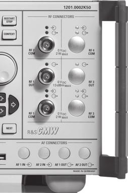
10 Spectrum measurements FFT spectrum analyzer (R&S CMW-KM010 option) 70 MHz to 3300 MHz up to 6000 MHz with R&S CMW-KB036 option Frequency span 1.25 MHz, 2.5 MHz, 5 MHz, 10 MHz, 20 MHz, 40 MHz FFT length 1k, 2k, 4k, 8k, 16k Detector peak, RMS Level range Level uncertainty for center frequency and detector peak Dynamic range 70 MHz to 3300 MHz, >100 db for FFT length 16k and span 5 MHz (equivalent to RBW 781 Hz) Expected nominal power setting for full dynamic range RF1 COM, RF2 COM 8 dbm to +42 dbm 5 Dynamic range 3300 MHz to 6000 MHz, >97 db for FFT length 16k and span 5 MHz (equivalent to RBW 781 Hz) Expected nominal power setting for full dynamic range RF1 COM, RF2 COM +2 dbm to +42 dbm 5 Inherent spurious response without input signal RF path 2 with RF TRX (R&S CMW-B570 option) and RF frontend (BASIC) (R&S CMW-B590A option) 6 The R&S CMW-B570 and R&S CMW-B590A options make the second RF path (RF path 2) available on the front of the instrument with three additional RF connectors, i.e. RF3 COM, RF4 COM and RF3 OUT. RF3 COM equivalent to RF1 COM RF4 COM equivalent to RF2 COM RF3 OUT equivalent to RF1 OUT 5 6 The maximum permissible continuous power is +34 dbm due to thermal limits. R&S CMW500 only. 10 Rohde & Schwarz R&S CMW500 Wideband Radio Communication Tester
11 Timebase Timebase TCXO Max. frequency drift in temperature range +5 C to +45 C ± Max. aging at +25 C, ± /year after 14 days of continuous operation Timebase basic OCXO (R&S CMW-B690A option) Max. frequency drift in temperature range +5 C to +45 C ± Retrace at +25 C, ± after 24 hours power ON / 2 hours power OFF / 1 hour power ON Max. aging at +25 C, after 10 days of continuous operation ± /year ± /day Warm-up time at +25 C, the frequency is in the range that is 10 times the frequency drift (± ) approx. 10 min Timebase highly stable OCXO (R&S CMW-B690B option) Max. frequency drift Retrace Max. aging Warm-up time Reference frequency inputs/outputs in temperature range +5 C to +45 C, ± referenced to +25 C with instrument orientation ± at +25 C, ± after 24 hours power ON / 2 hours power OFF / 1 hour power ON at +25 C, ± /year after 10 days of continuous operation ± /day at +25 C, approx. 10 min the frequency is in the range that is 10 times the frequency drift (± ) Synchronization input BNC connector REF IN, rear panel Frequency sinewave 10 MHz to 80 MHz, step: 1 Hz squarewave (TTL level) 1 MHz to 80 MHz, step: 1 Hz Max. frequency variation ± Input voltage range 0.5 V to 2 V, RMS Impedance 50 Ω Synchronization output 1 Frequency Output voltage Impedance BNC connector REF OUT 1, rear panel 10 MHz from internal reference or frequency at synchronization input >1.4 V, peak-to-peak 50 Ω Rohde & Schwarz R&S CMW500 Wideband Radio Communication Tester 11
12 GSM specifications mobile station test GSM RF generator (prerequisite: R&S CMW-B110A option) GSM 450 band 460 MHz to 468 MHz GSM 480 band 488 MHz to 496 MHz GSM 750 band 747 MHz to 762 MHz GSM 850 band 869 MHz to 894 MHz GSM 900 band 921 MHz to 960 MHz GSM 1800 band 1805 MHz to 1880 MHz GSM 1900 band 1930 MHz to 1990 MHz GSM GEN (R&S CMW-KG200 option) Output level range depending on PAR Output level uncertainty Output level resolution Signal quality Phase error GMSK <1, RMS <4, peak Error vector magnitude (EVM) 8PSK <2 %, RMS GSM WINIQSIM2 (R&S CMW-KW200 option) Arbitrary waveform files GMSK, B T = 0.3 8PSK GSM_GMSK.WV (PAR = 0 db), GMSKDIGMOD.WV (PAR = 0 db) GSM_EDGE.WV (PAR = 3.23 db), EDGEDIGMOD.WV (PAR = 3.22 db) Output level range depending on PAR Output level uncertainty GMSKDIGMOD.WV or EDGEDIGMOD.WV Output level resolution Signal quality Phase error Error vector magnitude (EVM) GMSK GSM_GMSK.WV 8PSK GSM_EDGE.WV <1, RMS <4, peak <2 %, RMS GSM RF analyzer (R&S CMW-KM200 option) GSM 450 band GSM 480 band GSM 750 band GSM 850 band GSM 900 band GSM 1800 band GSM 1900 band 450 MHz to 458 MHz 478 MHz to 486 MHz 777 MHz to 792 MHz 824 MHz to 849 MHz 876 MHz to 915 MHz 1710 MHz to 1785 MHz 1850 MHz to 1910 MHz Trigger Trigger sources BASE: external TRIG A, BASE: external TRIG B, GPRF: BB generator, GSM: free run, GSM: IF power, GSM: acquisition 12 Rohde & Schwarz R&S CMW500 Wideband Radio Communication Tester
13 Modulation analysis Level range 28 dbm to +42 dbm 7 Inherent phase error GMSK <0.6, RMS <2, peak Inherent error vector magnitude 8PSK <0.8 %, RMS (inherent EVM) Frequency measurement uncertainty <35 Hz + drift of timebase, Inherent I/Q offset < 50 db Filter GMSK bandpass, 900 khz, RRC filter, α = PSK windowed raised-cosine filter in line with 3GPP TS Burst power measurement Level uncertainty bandpass, 900 khz, RRC filter, α = 0.16 Power versus time measurement Filter selectable Gaussian, 500 khz or 1 MHz Dynamic range Expected nominal power setting for full dynamic range filter 500 khz, Gaussian, with fixed expected nominal power setting GMSK >72 db, RMS 8PSK >69 db, RMS RF1 COM, RF2 COM 8 dbm to +42 dbm 7 Relative measurement uncertainty result > 40 db typ. <0.1 db 60 db result 40 db typ. <0.5 db Burst power measurement Level range 50 dbm to +42 dbm 7 Level uncertainty filter 500 khz or 1 MHz, Gaussian Spectrum due to modulation measurement Expected nominal power setting for full RF1 COM, RF2 COM 8 dbm to +42 dbm 7 dynamic range Test method relative measurement, averaging Filter Gaussian, 30 khz, 5 pole Measurement at an offset of ± 100/200/250/400/600/800/1000/1200/1400 /1600/1800 khz Dynamic range offset 1200 khz GMSK 8PSK >74 db >70 db Spectrum due to switching measurement Expected nominal power setting for full RF1 COM, RF2 COM 8 dbm to +42 dbm 7 dynamic range Test method absolute measurement, Max Hold Filter Gaussian, 30 khz, 5 pole Measurement at an offset of ± 400/600/1200/1800 khz Dynamic range offset 1200 khz GMSK 8PSK >72 db >68 db 7 The maximum permissible continuous power is +34 dbm due to thermal limits. Rohde & Schwarz R&S CMW500 Wideband Radio Communication Tester 13
14 WCDMA specifications mobile station (UE) test Standard 3GPP FDD WCDMA RF generator (prerequisite: R&S CMW-B110A option) WCDMA band 1 WCDMA band 2 WCDMA band 3 WCDMA band 4 WCDMA band 5 WCDMA band 6 WCDMA band 7 WCDMA band 8 WCDMA band 9 WCDMA band 10 WCDMA band 11 WCDMA band 12 WCDMA band 13 WCDMA band MHz to 2170 MHz 1930 MHz to 1990 MHz 1805 MHz to 1880 MHz 2110 MHz to 2155 MHz 869 MHz to 894 MHz 875 MHz to 885 MHz 2620 MHz to 2690 MHz 925 MHz to 960 MHz MHz to MHz 2110 MHz to 2170 MHz MHz to MHz 728 MHz to 746 MHz 746 MHz to 756 MHz 758 MHz to 768 MHz WCDMA GEN (R&S CMW-KG400 option), WCDMA HSPA GEN (R&S CMW-KG401 option) Output level range depending on PAR Output level uncertainty Output level resolution Signal quality Error vector magnitude (EVM) composite EVM <4 %, RMS WCDMA WINIQSIM2 (R&S CMW-KW400 option), WCDMA HSDPA WINIQSIM2 (R&S CMW-KW401 option), WCDMA HSUPA WINIQSIM2 (R&S CMW-KW402 option) Arbitrary waveform files with R&S CMW-KW400 option with R&S CMW-KW401 option with R&S CMW-KW402 option TM4CPICH.WV (PAR = 8.34 db), 3GPPDEFAULT.WV (PAR = db) WCDMA_DL_HSDPA.WV (PAR = db) WCDMA_DL_HSUPA.WV (PAR = db) Output level range depending on PAR Output level uncertainty with R&S CMW-KW400 option 3GPPDEFAULT.WV with R&S CMW-KW401 option WCDMA_DL_HSDPA.WV with R&S CMW-KW402 option WCDMA_DL_HSUPA.WV Output level resolution Signal quality Error vector magnitude (EVM) composite EVM, with R&S CMW-KW400 option 3GPPDEFAULT.WV composite EVM, with R&S CMW-KW401 option WCDMA_DL_HSDPA.WV, composite EVM, with R&S CMW-KW402 option WCDMA_DL_HSUPA.WV <4 %, RMS <4 %, RMS <4 %, RMS 14 Rohde & Schwarz R&S CMW500 Wideband Radio Communication Tester
15 WCDMA RF analyzer (R&S CMW-KM400 option and R&S CMW-KM401 option) WCDMA band 1 WCDMA band 2 WCDMA band 3 WCDMA band 4 WCDMA band 5 WCDMA band 6 WCDMA band 7 WCDMA band 8 WCDMA band 9 WCDMA band 10 WCDMA band 11 WCDMA band 12 WCDMA band 13 WCDMA band MHz to 1980 MHz 1850 MHz to 1910 MHz 1710 MHz to 1785 MHz 1710 MHz to 1755 MHz 824 MHz to 849 MHz 830 MHz to 840 MHz 2500 MHz to 2570 MHz 880 MHz to 915 MHz MHz to MHz 1710 MHz to 1770 MHz MHz to MHz 698 MHz to 716 MHz 777 MHz to 787 MHz 788 MHz to 798 MHz Statistics Statistical count 1 to 1000 Values current, average, minimum/maximum, standard deviation Trigger Trigger sources BASE: external TRIG A, BASE: external TRIG B, GPRF: BB generator, WCDMA: free run, WCDMA: free run (fast sync), WCDMA: IF power, WCDMA: DCCH TTI trigger, WCDMA: frame trigger, WCDMA: HS-DPCCH trigger, WCDMA: slot trigger Modulation analysis Filter 3.84 MHz, RRC, α = 0.22, WCDMA filter Level range 28 dbm to +42 dbm 8 Analysis modes with R&S CMW-KM400 option QPSK, WCDMA with R&S CMW-KM400 option and R&S CMW-KM401 option WCDMA + HSDPA, WCDMA + HSUPA, WCDMA + HSPA Measured parameters numeric results and standard deviation error vector magnitude (EVM), magnitude error (ME), phase error (PE), frequency error, I/Q origin offset, I/Q imbalance, UE power, power steps, phase discontinuity, CDP, CDE graphical EVM versus time, EVM versus chip, ME versus time, ME versus chip, PE versus time, PE versus chip, FE versus time, UE versus time, PS versus slot, PD versus slot, CDP versus slot, CDE versus slot, CD monitor 8 The maximum permissible continuous power is +34 dbm due to thermal limits. Rohde & Schwarz R&S CMW500 Wideband Radio Communication Tester 15
16 Error vector magnitude (EVM) Measurement range up to 25 %, RMS Inherent EVM <2.5 %, RMS Measurement length half-slot, 1 slot, multislot (1 to 120) Frequency error Measurement range Frequency measurement uncertainty ±3 khz <35 Hz + drift of timebase, I/Q origin offset Inherent I/Q offset for average 10 measurements < 55 db I/Q imbalance Inherent I/Q imbalance Spectrum measurements Adjacent channel leakage ratio Filter Dynamic range Expected nominal power setting for full dynamic range Uncertainty Measurement length < 50 db RMS detector 3.84 MHz, RRC, α = 0.22, WCDMA filter first adjacent channel at ±5 MHz >54 db second adjacent channel at ±10 MHz >57 db RF1 COM, RF2 COM 4 dbm to +42 dbm 9 for 33 dbc first adjacent channel level <0.5 db for 43 dbc second adjacent channel level <0.5 db 1 slot (2560 chip) Power meter UE power measurement RMS detector Filter bandpass, 6.3 MHz, RRC, α = 0.22 Level range 55 dbm to +42 dbm 9 Level uncertainty Measurement length half-slot, 1 slot Off power measurement RMS detector Filter 3.84 MHz, RRC, α = 0.22, WCDMA filter Noise floor 72 dbm Level uncertainty + uncertainty due to noise floor 9 The maximum permissible continuous power is +34 dbm due to thermal limits. 16 Rohde & Schwarz R&S CMW500 Wideband Radio Communication Tester
17 LTE specifications mobile station test Standard LTE FDD and TDD LTE RF generator (prerequisite: R&S CMW-B110A option) E-UTRA band 1, FDD 2110 MHz to 2170 MHz E-UTRA band 2, FDD 1930 MHz to 1990 MHz E-UTRA band 3, FDD 1805 MHz to 1880 MHz E-UTRA band 4, FDD 2110 MHz to 2155 MHz E-UTRA band 5, FDD 869 MHz to 894 MHz E-UTRA band 6, FDD 875 MHz to 885 MHz E-UTRA band 7, FDD 2620 MHz to 2690 MHz E-UTRA band 8, FDD 925 MHz to 960 MHz E-UTRA band 9, FDD MHz o MHz E-UTRA band 10, FDD 2110 MHz to 2170 MHz E-UTRA band 11, FDD MHz to MHz E-UTRA band 12, FDD 728 MHz to 746 MHz E-UTRA band 13, FDD 746 MHz to 756 MHz E-UTRA band 14, FDD 758 MHz to 768 MHz E-UTRA band 17, FDD 734 MHz to 746 MHz E-UTRA band 33, TDD 1900 MHz to 1920 MHz E-UTRA band 34, TDD 2010 MHz to 2025 MHz E-UTRA band 35, TDD 1850 MHz to 1910 MHz E-UTRA band 36, TDD 1930 MHz to 1990 MHz E-UTRA band 37, TDD 1910 MHz to 1930 MHz E-UTRA band 38, TDD 2570 MHz to 2620 MHz E-UTRA band 39, TDD 1880 MHz to 1920 MHz E-UTRA band 40, TDD 2300 MHz to 2400 MHz LTE WINIQSIM2 (R&S CMW-KW500 option) Arbitrary waveform file LTE FDD LTE TDD LTE_FDD_QPSK_10MHZ.WV (PAR = db) LTE_TDD_64QAM_20MHZ.WV (PAR = db) Output level range depending on PAR Output level uncertainty LTE_FDD_QPSK_10MHZ.WV add 0.15 db to RF generator level uncertainty (see general technical specifications) Output level resolution LTE_TDD_64QAM_20MHZ.WV add 0.15 db to RF generator level uncertainty (see general technical specifications) Signal quality Error vector magnitude (EVM) EVM PDSCH QPSK, bandwidth = 10 MHz, 50 resource blocks, PRB symbol offset = 3, 10 subframes, PCFICH present LTE_FDD_QPSK_10MHZ.WV EVM PDSCH 64QAM, bandwidth = 20 MHz, 100 resource blocks, PRB symbol offset = 2, uplink/downlink configuration 1, special subframe configuration 7 LTE_TDD_64QAM_20MHZ.WV <4 %, RMS <4 %, RMS Rohde & Schwarz R&S CMW500 Wideband Radio Communication Tester 17
18 LTE FDD RF analyzer (R&S CMW-KM500 option) Bandwidth 1.4 MHz, 3 MHz, 5 MHz, 10 MHz, 15 MHz, 20 MHz Level setting E-UTRA band 1, FDD E-UTRA band 2, FDD E-UTRA band 3, FDD E-UTRA band 4, FDD E-UTRA band 5, FDD E-UTRA band 6, FDD E-UTRA band 7, FDD E-UTRA band 8, FDD E-UTRA band 9, FDD E-UTRA band 10, FDD E-UTRA band 11, FDD E-UTRA band 12, FDD E-UTRA band 13, FDD E-UTRA band 14, FDD E-UTRA band 17, FDD 1920 MHz to 1980 MHz 1850 MHz to 1910 MHz 1710 MHz to 1785 MHz 1710 MHz to 1755 MHz 824 MHz to 849 MHz 830 MHz to 840 MHz 2500 MHz to 2570 MHz 880 MHz to 915 MHz MHz MHz 1710 MHz to 1770 MHz MHz to MHz 698 MHz to 716 MHz 777 MHz to 787 MHz 788 MHz to 798 MHz 704 MHz to 716 MHz manual mode Statistics Statistical count 1 to 1000 Values current, average, minimum/maximum, standard deviation Trigger Trigger source BASE: external TRIG A, BASE: external TRIG B, GPRF: BB generator, LTE: free run (fast sync), LTE: IF power Power measurement Slot power Level range Level uncertainty Modulation analysis Measured parameters RMS detector numeric results graphical 50 dbm to +30 dbm, RMS error vector magnitude (EVM), magnitude error (ME), phase error (PE), frequency error, I/Q origin offset, TX power, peak power, resource block power (RB power) EVM versus SC-FDMA symbol, ME versus SC-FDMA symbol, PE versus SC-FDMA symbol, EVM versus subcarrier, inband emissions, spectrum flatness, I/Q constellation Error vector magnitude (EVM) Inherent EVM allocated resource blocks dbm input level < +30 dbm, <1 %, RMS RMS allocated resource blocks dbm input level +30 dbm, RMS <1 %, RMS 38 dbm input level < 30 dbm, RMS <1.5 %, RMS allocated resource blocks dbm input level +30 dbm, RMS <1 %, RMS 38 dbm input level < 30 dbm, RMS <2 %, RMS 18 Rohde & Schwarz R&S CMW500 Wideband Radio Communication Tester
19 Frequency error Measurement range Frequency measurement uncertainty ±80 khz <35 Hz + drift of timebase, I/Q origin offset Inherent I/Q offset for average 10 measurements < 50 db Inband Emissions Dynamic range allocated resource blocks 50 >50 db Expected nominal power setting for full dynamic range RF1 COM, RF2 COM +2 dbm to +42 dbm 10 Spectrum flatness Level uncertainty Spectrum measurements Adjacent channel leakage ratio Filter Dynamic range Expected nominal power setting for full dynamic range <0.5 db E-UTRA rectangle 1.08 MHz, 2.7 MHz, 4.5 MHz, 9 MHz, 13.5 MHz, 18 MHz UTRA 3.84 MHz, RRC, α = 0.22, WCDMA filter E-UTRA >45 db UTRA >54 db RF1 COM, RF2 COM +2 dbm to +42 dbm 10 SEM Frequency span Noise floor RBW 1 MHz RBW 100 khz RBW 30 khz 70 MHz < 35dBm < 40 dbm < 45 dbm LTE TDD RF analyzer (R&S CMW-KM550 option) Bandwidth 1.4 MHz, 3 MHz, 5 MHz, 10 MHz, 15 MHz, 20 MHz Level setting E-UTRA band 33, TDD E-UTRA band 34, TDD E-UTRA band 35, TDD E-UTRA band 36, TDD E-UTRA band 37, TDD E-UTRA band 38, TDD E-UTRA band 39, TDD E-UTRA band 40, TDD 1900 MHz to 1920 MHz 2010 MHz to 2025 MHz 1850 MHz to 1910 MHz 1930 MHz to 1990 MHz 1910 MHz to 1930 MHz 2570 MHz to 2620 MHz 1880 MHz to 1920 MHz 2300 MHz to 2400 MHz manual mode Statistics Statistical count 1 to 1000 Values current, average, minimum/maximum, standard deviation Trigger Trigger source BASE: external TRIG A, BASE: external TRIG B, GPRF: BB generator, LTE: free run (fast sync), LTE: IF power 10 The maximum permissible continuous power is +34 dbm due to thermal limits. Rohde & Schwarz R&S CMW500 Wideband Radio Communication Tester 19
20 Power measurement Slot power Level range Level uncertainty Modulation analysis Measured parameters RMS detector numeric results graphical 50 dbm to +30 dbm, RMS error vector magnitude (EVM), magnitude error (ME), phase error (PE), frequency error, I/Q origin offset, TX power, peak power, resource block power (RB power) EVM versus SC-FDMA symbol, ME versus SC-FDMA symbol, PE versus SC-FDMA symbol, EVM versus subcarrier, inband emissions, spectrum flatness, I/Q constellation Error vector magnitude (EVM) Inherent EVM Frequency error Measurement range Frequency measurement uncertainty I/Q origin offset Inherent I/Q offset allocated resource blocks dbm input level < +30 dbm, <1 %, RMS RMS allocated resource blocks dbm input level +30 dbm, RMS <1 %, RMS 38 dbm input level < 30 dbm, RMS <1.5 %, RMS allocated resource blocks dbm input level +30 dbm, RMS <1 %, RMS 38 dbm input level < 30 dbm, RMS <2 %, RMS ±80 khz <35 Hz + drift of timebase, < 50 db Inband emissions Dynamic range allocated resource blocks 50 >50 db Expected nominal power setting for full dynamic range RF1 COM, RF2 COM +2 dbm to +42 dbm 11 Spectrum flatness Level uncertainty Spectrum measurements Adjacent channel leakage ratio Filter E-UTRA UTRA <0.5 db rectangle 1.08 MHz, 2.7 MHz, 4.5 MHz, 9 MHz, 13.5 MHz, 18 MHz 1.28 MHz, RRC, α = 0.22, WCDMA filter Dynamic range Expected nominal power setting for full dynamic range E-UTRA >45 db UTRA >54 db RF1 COM, RF2 COM +2 dbm to +42 dbm The maximum permissible continuous power is +34 dbm due to thermal limits. 20 Rohde & Schwarz R&S CMW500 Wideband Radio Communication Tester
21 SEM Frequency span Noise floor RBW 1 MHz RBW 100 khz RBW 30 khz 70 MHz < 35dBm < 40dBm < 45 dbm Rohde & Schwarz R&S CMW500 Wideband Radio Communication Tester 21
22 Bluetooth specifications Standard standard test standard Bluetooth Core Specification Version 2.1 +EDR Radio Frequency Test Specification V1.2/V2.0/V2.0+EDR/V2.1/V2.1+EDR Bluetooth RF generator (prerequisite: R&S CMW-B110A option) Bluetooth 2402 MHz to 2481 MHz Bluetooth WINIQSIM2 (R&S CMW-KW610 option) Arbitrary waveform file basic rate enhanced data rate (EDR) BLUETOOTH_ _DH5.WV LAP: , (PAR = 0.00 db) BLUETOOTH_PRBS9_3-DH5.WV LAP: , (PAR = 3.17 db) Output level range depending on PAR Output level uncertainty waveform files used: BLUETOOTH_ _DH5.WV BLUETOOTH_PRBS_3-DH5.WV Output level resolution Signal quality Modulation index uncertainty basic rate, frequency deviation Δf1max = 160 khz BLUETOOTH_ _DH5.WV Differential error vector magnitude (DEVM) enhanced data rate, BLUETOOTH_PRBS9_3-DH5.WV <1 % <1.5 %, RMS Bluetooth RF analyzer (R&S CMW-KM610 option) Bluetooth 2402 MHz to 2481 MHz Statistics Statistical count 1 to 1000 Values current, average, maximum, minimum, standard deviation Trigger Trigger sources BT: IF power 22 Rohde & Schwarz R&S CMW500 Wideband Radio Communication Tester
23 Modulation analysis Filter filter bandwidth wide bandpass 2.0 MHz filter bandwidth narrow bandpass 1.3 MHz Level range 35 dbm to +42 dbm 12 Supported packet types basic rate DH1, DH3, DH5 enhanced data rate (EDR) 2-DH1, 2-DH3, 2-DH5, 3-DH1, 3-DH3, 3-DH5 Measured parameters basic rate, numeric results and standard deviation Δf %, frequency accuracy, frequency drift, max drift rate, frequency deviation Δf1 average, frequency deviation Δf1 minimum, frequency deviation Δf1 maximum, frequency deviation Δf2 average, frequency deviation Δf2 minimum, frequency deviation Δf2 maximum, nominal power Measured parameters enhanced data rate (EDR), numeric results and standard deviation 99 % DEVM, frequency stability ω i, frequency stability (ω o + ω i ) max, frequency stability ω o max, RMS DEVM, peak RMS, nominal power Total measurement range for frequency accuracy, frequency deviation and frequency drift basic rate ±250 khz Frequency accuracy basic rate Measurement range for nominal deviation of 160 khz ±100 khz Uncertainty for deviation 160 khz <2 khz Frequency deviation average basic rate Measurement range without frequency offset 210 khz Uncertainty for modulation index 0.22 to 0.42 <1 % Frequency drift Measurement range Uncertainty basic rate measured in burst related to frequency offset in preamble with pattern ±50 khz <2 khz Frequency stability ω i enhanced data rate Measurement range ±100 khz Uncertainty for ω i 75 khz, for deviation 160 khz <2 khz Frequency stability ω o max enhanced data rate Measurement range ±15 khz Uncertainty for ω o 10 khz <1 khz Differential error vector magnitude enhanced data rate (DEVM) Inherent DEVM for PRBS pattern <1.5 %, RMS <3.0 %, peak 12 The maximum permissible continuous power is +34 dbm due to thermal limits. Rohde & Schwarz R&S CMW500 Wideband Radio Communication Tester 23
24 GPS specifications Standard GPS GPS RF generator (prerequisite: R&S CMW-B110A option) GPS band L MHz L MHz GPS WINIQSIM2 (R&S CMW-KW620 option) Arbitrary waveform file GPS_DEFAULT.WV (PAR = 3.66 db) Output level range depending on PAR Output level uncertainty GPS_DEFAULT.WV Output level resolution DVB specifications Standard DVB-T DVB RF generator (prerequisite: R&S CMW-B110A option) VHF band III channels 5 to MHz to 230 MHz UHF band IV channels 21 to MHz to 582 MHz UHF band V channels 35 to MHz to 862 MHz DVB WINIQSIM2 (R&S CMW-KW630 option) Arbitrary waveform file DVB-T_SCRAMBLED_16QAM_3SEC_ TESTFILE.WV (PAR = db) Output level range depending on PAR Output level uncertainty DVB-T_SCRAMBLED_16QAM_3SEC_ TESTFILE.WV Output level resolution 24 Rohde & Schwarz R&S CMW500 Wideband Radio Communication Tester
25 WLAN specifications Standard IEEE a, IEEE b, IEEE g, IEEE n WLAN RF generator (prerequisite: R&S CMW-B110A option) WLAN IEEE b/g/n (2.4 GHz band) WLAN IEEE a/n (5 GHz band) prerequisite: R&S CMW-KB036 option WLAN ABG WINIQSIM2 (R&S CMW-KW650 option) Arbitrary waveform files 2412 MHz to 2484 MHz 5000 MHz to 6000 MHz in line with IEEE a/g OFDM 64QAM WLAN_A_G_OFDM_64QAM.WV (PAR = db) in line with IEEE b CCK DQPSK WLAN_B_CCK_DQPSK.WV (PAR = 1.48 db) Output level range depending on PAR Output level uncertainty waveform files used: WLAN_A_G_OFDM_64QAM.WV WLAN_B_CCK_DQPSK.WV add 0.15 db to RF generator output level uncertainty (see general technical specifications) Output level resolution Signal quality Error vector magnitude (EVM) IEEE a/g EVM all carriers WLAN_A_G_OFDM_64QAM.WV IEEE b EVM burst WLAN_B_CCK_DQPSK.WV < 40 db, RMS <4 %, peak WLAN N WINIQSIM2 (R&S CMW-KW651 option) Arbitrary waveform files in line with IEEE n 64QAM code rate 5/6 WLAN_N_64QAM_5_6.WV (PAR = db) Output level range depending on PAR Output level uncertainty waveform files used: WLAN_N_64QAM_5_6.WV add 0.15 db to RF generator output level uncertainty (see general technical specifications) Output level resolution Signal quality Error vector magnitude (EVM) IEEE n EVM all carriers WLAN_N_64QAM_5_6.WV WLAN ABG RF analyzer (R&S CMW-KM650 option) WLAN IEEE b/g WLAN IEEE a prerequisite: R&S CMW-KB036 option < 40 db, RMS 2412 MHz to 2484 MHz 5000 MHz to 6000 MHz Statistics Statistical count 1 to 1000 Values current, average, maximum, standard deviation Rohde & Schwarz R&S CMW500 Wideband Radio Communication Tester 25
26 Trigger Trigger sources WLAN: free run WLAN: IF power Modulation analysis Filter 20 MHz Level range 28 dbm to +42 dbm 13 Payload Length 16 symbols or 403 bytes Analysis modes DSSS 1 Mbps DBPSK, 2 Mbps DQPSK, 5.5 Mbps CCK, 11 Mbps CCK OFDM 6 Mbps BPSK, 9 Mbps BPSK, 12 Mbps QPSK, 18 Mbps QPSK, 24 Mbps 16QAM, 36 Mbps 16QAM, 48 Mbps 64QAM, 54 Mbps 64QAM Measured parameters DSSS, numeric results and standard deviation burst power, error vector magnitude (EVM) peak, error vector magnitude (EVM) RMS, center frequency error, chip clock error, I/Q offset, gain imbalance, quadrature error OFDM, numeric results and standard deviation burst power, EVM all carriers, EVM data carriers, EVM pilot carriers, center frequency error, symbol clock error, I/Q offset, gain imbalance, quadrature error Error vector magnitude (EVM) Inherent EVM Measurement length Error vector magnitude (EVM) Inherent EVM Measurement length Center frequency error Frequency measurement uncertainty DSSS IEEE b/g OFDM IEEE g IEEE a DSSS <5 %, peak <2 %, RMS 1000 samples < 40 db, RMS < 37 db, RMS entire PPDU <35 Hz + drift of timebase, Center frequency error OFDM Frequency measurement uncertainty for 100 symbol (400 μs) <35 Hz + drift of timebase Chip clock error Uncertainty Symbol clock error Uncertainty DSSS OFDM <1 ppm <1 ppm 13 The maximum permissible continuous power is +34 dbm due to thermal limits. 26 Rohde & Schwarz R&S CMW500 Wideband Radio Communication Tester
27 I/Q offset DSSS Inherent I/Q offset for average 10 measurements < 50 db I/Q offset OFDM Inherent I/Q offset for average 10 measurements < 45 db WLAN N RF analyzer (R&S CMW-KM651 option) WLAN IEEE n (2.4 GHz band) WLAN IEEE n (5 GHz band) prerequisite: R&S CMW-KB036 option 2412 MHz to 2484 MHz 5000 MHz to 6000 MHz Statistics Statistical count 1 to 1000 Values current, average, maximum, standard deviation Trigger Trigger sources WLAN: free run WLAN: IF power Modulation analysis Filter 20 MHz Level range 28 dbm to +42 dbm 14 Payload length 16 symbols or 403 bytes Analysis modes BPSK code rate 1/2, BPSK code rate 3/4, QPSK code rate 1/2, QPSK code rate 3/4, 16QAM code rate 1/2, 16QAM code rate 3/4, 64QAM code rate 1/2, 64QAM code rate 2/3, 64QAM code rate 3/4, 64QAM code rate 5/6 Measured parameters numeric results and standard deviation burst power EVM all carriers, EVM data carriers, EVM pilot carriers, center frequency error, symbol clock error, I/Q offset, gain imbalance, quadrature error Error vector magnitude (EVM) Inherent EVM IEEE n < 40 db, RMS Measurement length entire PPDU Center frequency error Frequency measurement uncertainty for 100 symbol (400 µs) <35 Hz + drift of timebase Symbol clock error Uncertainty <1 ppm I/Q offset Inherent I/Q offset for average 10 measurements < 45 db 14 The maximum permissible continuous power is +34 dbm due to thermal limits. Rohde & Schwarz R&S CMW500 Wideband Radio Communication Tester 27
28 TD-SCDMA specifications mobile station (UE) test Standard TD-SCDMA CWTS TD-SCDMA RF generator (prerequisite: R&S CMW-B110A option) TD-SCDMA band I channels 9512 to MHz to 1920 MHz channels to MHz to 2025 MHz TD-SCDMA band II channels 9262 to MHz to 1910 MHz channels 9662 to MHz to 1990 MHz TD-SCDMA band III channels 9562 to MHz to 1930 MHz TD-SCDMA WINIQSIM2 (R&S CMW-KW750 option) and TD-SCDMA ENH. WINIQSIM2 (R&S CMW-KW751 option) Arbitrary waveform files with R&S CMW-KW750 with R&S CMW-KW750 and R&S CMW-KW751 TD-SCDMA_DEFAULT.WV (PAR = 3.14 db), TD-SCDMA_PTWLOW.WV (PAR = 2.67 db) TD-SCDMA-DL_12K2.WV (PAR = 5.41 db) Output level range depending on PAR Output level uncertainty TD-SCDMA_PTWLOW.WV Output level resolution Signal quality Error vector magnitude (EVM) composite EVM, TD-SCDMA_DEFAULT.WV <4 %, RMS TD-SCDMA RF analyzer (R&S CMW-KM750 option) TD-SCDMA band I channels 9512 to 9588 channels to TD-SCDMA band II channels 9262 to 9538 channels 9662 to 9938 TD-SCDMA band III channels 9562 to MHz to 1920 MHz 2010 MHz to 2025 MHz 1850 MHz to 1910 MHz 1930 MHz to 1990 MHz 1910 MHz to 1930 MHz Statistics Statistical count 1 to 1000 Values current, average, minimum/maximum, standard deviation Trigger Trigger sources BASE: external TRIG A, BASE: external TRIG B, GPRF: BB generator, TD-SCDMA: free run, TD-SCDMA: IF power 28 Rohde & Schwarz R&S CMW500 Wideband Radio Communication Tester
29 Modulation analysis Filter 1.28 MHz, RRC, α = 0.22, TD-SCDMA filter Level range 28 dbm to +42 dbm 15 Analysis modes TD-SCDMA uplink DPCH, DPCH + HSDPA Measured parameters numeric results and standard deviation error vector magnitude (EVM), magnitude error (ME), phase error (PE), frequency error, I/Q origin offset, I/Q imbalance, UE power graphical EVM versus time, ME versus time, PE versus time Error vector magnitude (EVM) Measurement range up to 25 %, RMS Inherent EVM <2.5 %, RMS Measurement length 1 slot, multislot (1 to 112) Frequency error Measurement range Frequency measurement uncertainty ±3 khz <35 Hz + drift of timebase, I/Q origin offset Inherent I/Q offset for average 10 measurements < 55 db I/Q imbalance Inherent I/Q imbalance < 50 db 15 The maximum permissible continuous power is +34 dbm due to thermal limits. Rohde & Schwarz R&S CMW500 Wideband Radio Communication Tester 29
30 Code domain Filter 1.28 MHz, RRC, α = 0.22, TD-SCDMA filter Level range 28 dbm to +42 dbm 16 Analysis modes TD-SCDMA uplink DPCH, DPCH + HSDPA Measured parameters numeric results and standard deviation code domain error (CDE) graphical code domain power versus code Code domain power versus code Uncertainty Measurement length Code domain error (CDE) Uncertainty Measurement length Spectrum measurements Adjacent channel leakage ratio Filter Dynamic range Expected nominal power setting for full dynamic range Uncertainty Measurement length <0.4 db 1 slot <0.4 db 1 slot RMS detector 1.28 MHz, RRC, α = 0.22, TD-SCDMA filter first adjacent channel at ±1.6 MHz >53 db second adjacent channel at ±3.2 MHz >61 db RF1 COM, RF2 COM 3 dbm to +42 dbm 16 for 33 dbc first adjacent channel level <0.5 db for 43 dbc second adjacent channel level <0.5 db 1 slot Power meter Measured parameters numeric current RMS values UE power UE power RMS detector Filter bandpass, 2.1 MHz, RRC, α = 0.22 Level range 55 dbm to +42 dbm 16 Level uncertainty Measurement length 1 slot 16 The maximum permissible continuous power is +34 dbm due to thermal limits. 30 Rohde & Schwarz R&S CMW500 Wideband Radio Communication Tester
31 CDMA2000 1xRTT specifications mobile station test Standard CDMA2000 standards TIA/EIA IS-2000 Rev. 0 CDMA2000 test standards TIA/EIA IS-98-F Symbol rate Mcps CDMA2000 1xRTT RF generator (prerequisite: R&S CMW-B110A option) band class MHz to MHz band class MHz to MHz band class MHz to MHz band class MHz to MHz band class MHz to MHz band class MHz to MHz band class MHz to MHz band class MHz to MHz band class MHz to MHz band class MHz to MHz band class MHz to MHz band class MHz to MHz band class MHz to MHz band class MHz to 2690 MHz band class MHz to MHz band class MHz to MHz band class MHz to MHz band class MHz to MHz band class MHz to MHz band class MHz to MHz CDMA2000 WINIQSIM2 (R&S CMW-KW800 option) Arbitrary waveform files CDMA_OQPSK.WV (PAR = 5.54 db) or CDMA_HPSK.WV (PAR = 6.97 db) Output level range depending on PAR Output level uncertainty CDMA_OQPSK.WV or CDMA_HPSK.WV Output level resolution Signal quality Waveform quality (rho) CDMA_OQPSK.WV or CDMA_HPSK.WV >0.99 CDMA2000 RF analyzer (R&S CMW-KM800 option) band class MHz to MHz band class MHz to MHz band class MHz to MHz band class MHz to MHz band class MHz to MHz band class MHz to MHz band class MHz to MHz band class MHz to MHz band class MHz to MHz band class MHz to MHz band class MHz to MHz band class MHz to MHz band class MHz to MHz band class MHz to MHz band class MHz to MHz band class MHz to MHz band class MHz to MHz band class MHz to MHz band class MHz to MHz band class MHz to MHz Rohde & Schwarz R&S CMW500 Wideband Radio Communication Tester 31
32 Statistics Statistical count 1 to 1000 Values current, average, minimum/maximum, standard deviation Trigger Trigger sources BASE: external TRIG A, BASE: external TRIG B, GPRF: BB generator, C2K: free run Modulation analysis Filter 1.23 MHz, RRC, α = 0.22, CDMA filter Level range 28 dbm to +42 dbm 17 Analysis modes O-QPSK, HPSK Measured parameters numeric results and standard deviation error vector magnitude (EVM), magnitude error (ME), phase error (PE), frequency error, rho, carrier feedthrough, I/Q imbalance, power, wideband power (8 MHz), narrowband power (1.23 MHz) graphical EVM versus time, ME versus time, PE versus time Waveform quality (rho) Uncertainty for rho 0.9 to 1 <0.003 Measurement length 616 chip (0.5 ms) Error vector magnitude (EVM) Measurement range Inherent EVM Measurement length Frequency error Measurement range Frequency measurement uncertainty up to 25 %, RMS <2.5 %, RMS 0.5 ms ±3 khz <35 Hz + drift of timebase, Carrier feedthrough Inherent carrier feedthrough for average 10 measurements < 55 db I/Q imbalance Inherent I/Q imbalance < 50 db 17 The maximum permissible continuous power is +34 dbm due to thermal limits. 32 Rohde & Schwarz R&S CMW500 Wideband Radio Communication Tester
33 Code domain Filter 1.23 MHz, RRC, α = 0.22, CDMA filter Level range 28 dbm to +42 dbm 18 Measured parameters numeric values of current, average, max. code domain power (CDP), and min. values code domain error (CDE) graphical code domain power versus code, code domain error versus code Code domain power versus code Uncertainty Measurement length Code domain error versus code Measurement uncertainty Measurement length <0.4 db 616 chip (0.5 ms) <0.4 db 616 chip (0.5 ms) Spectrum measurements Adjacent channel power RMS detector, at the selected frequency offsets Filter 30 khz Gaussian Frequency offset interval up to 10 adjacent channels on each side 4 MHz to +4 MHz Dynamic range >70 db Expected nominal power setting for full RF1 COM, RF2 COM +1 dbm to +42 dbm 18 dynamic range Uncertainty for 43 dbc adjacent channel level <0.5 db Measurement length one power control group 1536 chip (1.25 ms) Power meter MS power Filter narrowband bandpass, 1.25 MHz Filter wideband bandpass, 8 MHz Level range 55 dbm to +42 dbm 18 Level uncertainty Measurement length 616 chip (0.5 ms) 18 The maximum permissible continuous power is +34 dbm due to thermal limits. Rohde & Schwarz R&S CMW500 Wideband Radio Communication Tester 33
34 CDMA2000 1xEV-DO specifications access terminal test Standard CDMA2000 1xEV-DO standards TIA/EIA CDMA2000 1xEV-DO test standards TIA/EIA 866-A, TIA/EIA 866-B Symbol rate Mcps CDMA2000 1xEV-DO RF generator (prerequisite: R&S CMW-B110A option) band class MHz to MHz band class MHz to MHz band class MHz to MHz band class MHz to MHz band class MHz to MHz band class MHz to MHz band class MHz to MHz band class MHz to MHz band class MHz to MHz band class MHz to MHz band class MHz to MHz band class MHz to MHz band class MHz to MHz band class MHz to 2690 MHz band class MHz to MHz band class MHz to MHz band class MHz to MHz band class MHz to MHz band class MHz to MHz band class MHz to MHz 1xEV-DO WINIQSIM2 (R&S CMW-KW880 option) Arbitrary waveform file EVDO_DEFAULT.WV (PAR = 4.86 db) Output level range depending on PAR Output level uncertainty EVDO_DEFAULT.WV Output level resolution Signal quality Waveform quality (rho) EVDO_DEFAULT.WV >0.99 CDMA2000 1xEV-DO RF analyzer (R&S CMW-KM880 option) band class 0 band class 1 band class 2 band class 3 band class 4 band class 5 band class 6 band class 7 band class 8 band class 9 band class 10 band class 11 band class 12 band class 13 band class 14 band class 15 band class 16 band class 17 band class 18 band class MHz to MHz MHz to MHz MHz to MHz MHz to MHz MHz to MHz MHz to MHz MHz to MHz MHz to MHz MHz to MHz MHz to MHz MHz to MHz MHz to MHz MHz to MHz MHz to MHz MHz to MHz MHz to MHz MHz to MHz MHz to MHz MHz to MHz MHz to MHz 34 Rohde & Schwarz R&S CMW500 Wideband Radio Communication Tester
R&S CMW100 Communications Manufacturing Test Set Specifications
 R&S CMW100 Communications Manufacturing Test Set Specifications Data Sheet Version 02.00 CONTENTS Definitions... 6 General technical specifications... 7 RF generator... 8 Modulation source: arbitrary waveform
R&S CMW100 Communications Manufacturing Test Set Specifications
 R&S CMW100 Communications Manufacturing Test Set Specifications R&S CMW100 model.k06 Data Sheet Version 03.00 CONTENTS Definitions... 4 General technical specifications... 5 RF generator... 6 RF analyzer...
R&S CMW500 Wideband Radio Communication Tester Specifications
 www.atecorp.com 800-404-ATEC (2832) R&S CMW500 Wideband Radio Communication Tester Specifications CMW500_dat-sw_en_5213-9211-22_v1100_cover.indd 1 Data Sheet 11.00 E stablished 1981 Advanced Test Equipment
LitePoint IQxstream-M
 TECHNICAL SPECIFICATIONS LitePoint IQxstream-M 2017 LitePoint, A Teradyne Company. All rights reserved. IQxstream-M is a manufacturing-oriented, multi-device, physical layer communication system tester,
From 2G to 4G UE Measurements from GSM to LTE. David Hall RF Product Manager
 From 2G to 4G UE Measurements from GSM to LTE David Hall RF Product Manager Agenda: Testing 2G to 4G Devices The progression of standards GSM/EDGE measurements WCDMA measurements LTE Measurements LTE theory
Vector Signal Generator SMJ100A
 Product brochure Version 01.00 Vector Signal Generator SMJ100A November May 2004 2005 Versatility in signal generation The multipurpose signal generator The SMJ100A meets all challenges that diverse applications
PXIe Contents SPECIFICATIONS. 14 GHz and 26.5 GHz Vector Signal Analyzer
 SPECIFICATIONS PXIe-5668 14 GHz and 26.5 GHz Vector Signal Analyzer These specifications apply to the PXIe-5668 (14 GHz) Vector Signal Analyzer and the PXIe-5668 (26.5 GHz) Vector Signal Analyzer with
Vector Signal Generator SMATE200A
 Product brochure Version 01.00 Vector Signal Generator SMATE200A May 2005 The production solution based on the SMU200A The new standard in production Based on the successful SMU200A platform, the SMATE200A
Reconfigurable 6 GHz Vector Signal Transceiver with I/Q Interface
 SPECIFICATIONS PXIe-5645 Reconfigurable 6 GHz Vector Signal Transceiver with I/Q Interface Contents Definitions...2 Conditions... 3 Frequency...4 Frequency Settling Time... 4 Internal Frequency Reference...
Advanced Test Equipment Rentals ATEC (2832) R&S FSL Spectrum Analyzer. Test & Measurement. Data Sheet
 R&S FSL Spectrum Analyzer. Test & Measurement. Data Sheet") Established 1981 Advanced Test Equipment Rentals www.atecorp.com 800-404-ATEC (2832) R&S FSL Spectrum Analyzer t Specifications Test & Measurement Data Sheet 09.00 CONTENTS Frequency... 5 Sweep time...
Established 1981 Advanced Test Equipment Rentals www.atecorp.com 800-404-ATEC (2832) R&S FSL Spectrum Analyzer t Specifications Test & Measurement Data Sheet 09.00 CONTENTS Frequency... 5 Sweep time...
R&S CBT/R&S CBT32 Bluetooth Tester Specifications
 Established 1981 Advanced Test Equipment Rentals www.atecorp.com 800-404-ATEC (2832) R&S CBT/R&S CBT32 Bluetooth Tester Specifications Test & Measurement Data Sheet 06.00 CONTENTS Unit specifications...
SMU200A Vector Signal Generator
 Version 07.00 SMU200A Vector Signal Generator December 2007 Data sheet CONTENTS Introduction...4 Key features...5 Frequency and enhancement options...6 Frequency options...6 Enhancement options...6 Modulation...6
R&S SMW200A Vector Signal Generator Specifications
 R&S SMW200A Vector Signal Generator Specifications year Data Sheet Version 04.04 CONTENTS Key features... 4 Definitions... 5 Frequency and baseband main module options... 6 Frequency options... 6 Signal
TECHNICAL SPECIFICATIONS. LitePoint IQxstream LitePoint, A Teradyne Company. All rights reserved.
 TECHNICAL SPECIFICATIONS LitePoint IQxstream 2017 LitePoint, A Teradyne Company. All rights reserved. IQxstream is a manufacturing oriented, physical layer communication system tester, tailored to verifying
PXI LTE FDD and LTE TDD Measurement Suites Data Sheet
 PXI LTE FDD and LTE TDD Measurement Suites Data Sheet The most important thing we build is trust A production ready ATE solution for RF alignment and performance verification UE Tx output power Transmit
R&S FSH Spectrum Analyzer Specifications
 FSH_dat_sw_en_5214-0482-22_cover.indd 1 Data Sheet 18.00 Test & Measurement R&S FSH Spectrum Analyzer Specifications 30.06.2014 12:11:22 CONTENTS Specifications... 3 Frequency... 3 Sweep time... 4 Bandwidths...
R&S FSH Handheld Spectrum Analyzer Specifications
 R&S FSH Handheld Spectrum Analyzer Specifications year Data Sheet Version 25.00 CONTENTS Definitions... 4 Specifications... 5 Frequency... 5 Sweep time... 6 Bandwidths... 6 Level... 6 Trigger functions...
MX2690xxA series MX2830xxA series MX2850xxA series
 Product Brochure Signal Analyzer MS2690A/MS2691A/MS2692A Signal Analyzer MS2850A/MS2840A/ MX2690xxA series MX2830xxA series MX2850xxA series Software MX2690xxA/MX2830xxA/MX2850xxA series Software Signal
Signal generators. Modular design for user-friendly solutions
 GENERAL PURPOSE 43985/1 FIG 1 Visionary: The new Vector Signal Generator R&S SMU200A offers two complete signal generators with digital modulation capability in a single instrument and facilitates the
EXT Wireless Communications Test Set E6607B. Data Sheet
 EXT Wireless Communications Test Set E6607B Data Sheet The Agilent Technologies E6607B EXT wireless communications test set integrates an innovative test sequencer, vector signal analyzer, vector signal
Vector Signal Generator SMU200A
 Specifications Version 02.00 Vector Signal Generator SMU200A June 2004 Specifications CONTENTS INTRODUCTION...3 KEY FEATURES...4 SPECIFICATIONS...5 FREQUENCY AND RF OPTIONS...5 Frequency options...5 RF
IQxel TM Next Generation Connectivity Test System
 TECHNICAL SPECIFICATIONS IQxel TM Next Generation Connectivity Test System 2017 LitePoint, A Teradyne Company. All rights reserved. General Technical Specifications RF Analyzer Parameter Ports Value Input
Agilent E4406A Vector Signal Analyzer
 Agilent E4406A Vector Signal Analyzer Data Sheet The Agilent Technologies E4406A vector signal analyzer (VSA) is a full-featured transmitter tester designed to meet the test needs of wireless equipment
R&S SMW200A Vector Signal Generator Specifications
 R&S SMW200A Vector Signal Generator Specifications year Data Sheet Version 07.00 CONTENTS Key features... 5 Definitions... 6 Frequency and baseband main module options... 7 Frequency options... 7 Signal
TRANSCOM Manufacturing & Education
 www.transcomwireless.com 1 G6 Vector Signal Generator Overview G6 Vector Signal Generator is a high performance vector signal generator. It can generate arbitrary wave signal, continuous wave signal, common
R&S ZVL Vector Network Analyzer Specifications
 R&S ZVL Vector Network Analyzer Specifications Data Sheet Version 10.00 CONTENTS Definitions... 3 Specifications... 4 Measurement range... 4 Measurement speed... 4 Measurement accuracy... 5 Effective system
VST 6 GHz RF Vector Signal Transceiver (VST)
") VST 6 GHz RF Vector Signal Transceiver (VST) 2016 Datasheet The most important thing we build is trust Key features Vector signal analyser and generator in a single 3U x 3 slot wide PXIe module 65 MHz
VST 6 GHz RF Vector Signal Transceiver (VST) 2016 Datasheet The most important thing we build is trust Key features Vector signal analyser and generator in a single 3U x 3 slot wide PXIe module 65 MHz
IQxel-M8 TM Multi-DUT Connectivity Test System
 TECHNICAL SPECIFICATIONS IQxel-M8 TM Multi-DUT Connectivity Test System 2017 LitePoint, A Teradyne Company. All rights reserved. Overview of IQxel-M8 The IQxel-M8 is a manufacturing oriented, Multi-DUT
R&S NRP-Zxx Power Sensors Specifications
 R&S NRP-Zxx Power Sensors Specifications year Data Sheet Version 11.00 CONTENTS Definitions... 3 Overview of the R&S NRP-Zxx power sensors... 4 Specifications in brief of the R&S NRP-Zxx power sensors...
Agilent E1969A TD-SCDMA_GSM Fast Switch Test Application
 Agilent E1969A TD-SCDMA_GSM Fast Switch Test Application For the 8960 Series 10 (E5515C/E) wireless communications test set Technical Overview Key Capabilities Test TD-HSPA devices (HS-DSCH Categories
Conformity and Interoperability Training Homologation Procedures and Type Approval Testing for Mobile Terminals
 Conformity and Interoperability Training Homologation Procedures and Type Approval Testing for Mobile Terminals ITU C&I Programme Training Course on Testing Mobile Terminal Schedule RF Tests (Functional)
IQgig-IF TM Technical Specifications
 TECHNICAL SPECIFICATIONS IQgig-IF TM Technical Specifications 2018 LitePoint, A Teradyne Company. All rights reserved. Port Descriptions IQgig-IF Front Panel I/O Function Type Power Switch Power On/Off
IQxel-M TM Multi-DUT/Multicom Connectivity Test System
 TECHNICAL SPECIFICATIONS IQxel-M TM Multi-DUT/Multicom Connectivity Test System 2017 LitePoint, A Teradyne Company. All rights reserved. Overview of IQxel-M The IQxel-M is a manufacturing oriented, Multi-DUT,
R&S SMW200A Vector Signal Generator Specifications
 SMW200A_dat-sw_en_3606-8037-22_v0302_cover.indd 1 Data Sheet 03.02 Test & Measurement R&S SMW200A Vector Signal Generator Specifications 19.03.2015 09:39:58 CONTENTS Key features... 4 Definitions... 5
PXI Studio. Application software for advanced RF digital communications test
 PXI Studio Application software for advanced RF digital communications test Vector Signal Generator and Vector Signal Analyzer /Spectrum Analyzer application software with options for wireless data and
IQxel-M8W TM Multi-DUT Connectivity Test System
 TECHNICAL SPECIFICATIONS IQxel-M8W TM Multi-DUT Connectivity Test System 2018 LitePoint, A Teradyne Company. All rights reserved. General Technical Specifications RF Analyzer Parameter Ports (A/B) Value
Vector Network Analyzers ZVB
 Specifications Version 05.00 Vector Network Analyzers ZVB September 2005 Specifications MEASUREMENT RANGE...3 MEASUREMENT SPEED...5 MEASUREMENT ACCURACY...6 EFFECTIVE SYSTEM DATA...8 TEST PORT OUTPUT...8
FMU36 Baseband Signal Analyzer
 Version 01.00 FMU36 Baseband Signal Analyzer January 2007 Specifications Contents SPECIFICATIONS... 3 FREQUENCY... 3 SWEEP... 3 RESOLUTION BANDWIDTHS... 3 LEVEL... 4 DYNAMIC RANGE... 5 PHASE... 5 PROBE
PXI. TD-SCDMA Measurement Suite Data Sheet. The most important thing we build is trust. Total Average Power plus Midamble / Data Power
 PXI TD-SCDMA Measurement Suite Data Sheet The most important thing we build is trust Total Average Power plus Midamble / Data Power Transmit On/Off Time Mask Transmit Closed Loop Power Control (CLPC) Spectrum
A passion for performance. Intuitive, fast, digital. modulation waveform. creation tool. making waves...
 A passion for performance. Intuitive, fast, digital modulation waveform creation tool TM making waves... Waveform Creation and Simulation Modulation Formats Designed for use with Aeroflex's digital RF
Real-Time Spectrum Analyzer Software Options Measurement Software Options for RSA3000A Series WCA200A Series
 Features & Benefits Trigger Tektronix Exclusive Frequency Mask Trigger Makes Eventbased Capture of Transient RF Signals Easy by Triggering on Any Change in the Frequency Domain Capture All Input Signals
PXI UMTS Uplink Measurement Suite Data Sheet
 PXI UMTS Uplink Measurement Suite Data Sheet The most important thing we build is trust A production ready ATE solution for RF alignment and performance verification Tx Max Output Power Frequency Error
Measuring Receiver FSMR
 Product brochure Version 01.00 02.00 Measuring Receiver FSMR November April 2004 2006 All-in-one solution for the calibration of signal generators and attenuators Frequency range from 20 Hz to 3/26.5/50
VIAVI VST. Data Sheet. 6 GHz RF Vector Signal Transceiver (VST)
") Data Sheet VIAVI 6 GHz RF Vector Signal Transceiver () VIAVI Solutions The Vector Signal Transceiver () is an essential building block in RF communications test solutions supplied by VIAVI Solutions. Overview
Data Sheet VIAVI 6 GHz RF Vector Signal Transceiver () VIAVI Solutions The Vector Signal Transceiver () is an essential building block in RF communications test solutions supplied by VIAVI Solutions. Overview
Measurement Guide and Programming Examples
 Measurement Guide and Programming Examples N9073A-1FP W-CDMA Measurement Application N9073A-2FP HSDPA/HSUPA Measurement Application For use with the Agilent N9020A MXA and N9010A EXA Signal Analyzers Manufacturing
R&S FSx-K91/-K91n, R&S FSW/FSQ-K91ac WLAN Application Firmware WLAN TX measurements with Rohde & Schwarz analyzers
 Test & Measurement Product Brochure 03.00 R&S FSx-K91/-K91n, R&S FSW/FSQ-K91ac WLAN Application Firmware WLAN TX measurements with Rohde & Schwarz analyzers R&S FSx-K91/-K91n R&S FSW-K91ac/ R&S FSQ-K91ac
PXI Studio. Application Software for Advanced RF Digital Communications Test
 PXI Studio Application Software for Advanced RF Digital Communications Test Vector Signal Generator and Vector Signal Analyzer /Spectrum Analyzer application software with options for wireless data and
A passion for performance. Intuitive, fast, digital. modulation waveform. creation tool. making waves...
 A passion for performance. Intuitive, fast, digital modulation waveform creation tool making waves... Waveform Creation and Simulation Modulation Formats Designed for use with Aeroflex's digital RF signal
Frequency range 100 khz to 3 GHz 100 khz to 6 GHz 10 MHz to 18 GHz Reference frequency. 2 ppm in addition 2 ppm/10 C. 0 Hz, 100 Hz to 3 GHz
 Specifications Specifications apply under the following conditions: 15 minutes warm-up time at ambient temperature, specified environmental conditions met, and calibration cycle adhered to. Data without
Agilent E1969A TD-SCDMA_GSM Fast Switch Test Application
 Agilent E1969A TD-SCDMA_GSM Fast Switch Test Application Includes E1969A-101 TD-SCDMA non-signaling test mode, E1969A-201 TD-SCMDA signaling mode, E1963A-403 TD-HSDPA and E1968A GSM/GPRS/EGPRS test application
IQgig-RF TM Model B Technical Specifications
 TECHNICAL SPECIFICATIONS IQgig-RF TM Model B Technical Specifications 2018 LitePoint, A Teradyne Company. All rights reserved. Port Descriptions IQgig-RF Test Controller Front Panel I/O Function Type Power
R&S SMW200A Vector Signal Generator Specifications
 www.atecorp.com 800-404-ATEC (2832) R&S SMW200A Vector Signal Generator Specifications SMW200A_dat-sw_en_3606-8037-22_v0102_cover.indd 1 Data Sheet 01.02 E stablished 1981 Advanced Test Equipment Rentals
Spectrum and signal analyzers for every requirement an overview
 Spectrum and signal analyzers for every requirement an overview The introduction of the Handheld Spectrum Analyzer R&S FSH6 (page 26) expands an already full range of analyzers from Rohde & Schwarz, covering
U90xxA X-Series Measurement Applications for the EXT Wireless Communications Test Set
 U90xxA X-Series Measurement Applications for the EXT Wireless Communications Test Set Leverage the industry-proven Agilent X-Series measurements applications for the EXT wireless communications test set
IQxel-M8 TM Multi-DUT Connectivity Test System
 TECHNICAL SPECIFICATIONS IQxel-M8 TM Multi-DUT Connectivity Test System 2015 LitePoint, A Teradyne Company. All rights reserved. Overview of IQxel-M8 The IQxel-M8 is a manufacturing oriented, Multi-DUTtest
R&S SMBV100A Vector Signal Generator Specifications
 R&S SMBV100A Vector Signal Generator Specifications Test & Measurement Data Sheet 01.01 CONTENTS Key features... 3 Specifications... 4 RF characteristics...4 Frequency...4 Frequency sweep...4 Reference
FSQ Signal Analyzer. Signal analysis with the dynamic range of a high-end spectrum analyzer and a demodulation bandwidth of up to 120 MHz
 Version 03.00 FSQ Signal Analyzer January 2007 Signal analysis with the dynamic range of a high-end spectrum analyzer and a demodulation bandwidth of up to 120 MHz Up to 3.6 GHz, 8 GHz, 26.5 GHz and 40
R&S ZN-Z5x Calibration Units Specifications. Data Sheet V03.00
 R&S ZN-Z5x Calibration Units Specifications Data Sheet V03.00 CONTENTS Definitions... 4 Specifications... 6 Model description R&S ZN-Z5x... 6 Model description R&S ZN-Z15x... 7 Input power limits... 7
RF Signal Generator SM300
 RF Signal Generator SM300 9 khz to 3 GHz With compliments Helmut Singer Elektronik www.helmut-singer.de info@helmut-singer.de fon +49 241 155 315 fax +49 241 152 066 Feldchen 16-24 D-52070 Aachen Germany
PXI Modules 3070A PXI High Performance RF Digitizer Data Sheet
 PXI Modules 3070A PXI High Performance RF Digitizer Data Sheet The most important thing we build is trust Continuous frequency range 250 MHz to 3 GHz or 6 GHz Input levels to +30 dbm with 1 db RF step
SAV102 NB-IoT Modular Signal Generator Datasheet
 SAV102 NB-IoT Modular Signal Generator Datasheet Saluki Technology Inc. The document applies to following models: SAV102 NB-IoT Modular Signal Generator Standard Accessories Main Machine Power adapter
IQxel-M2W TM R&D Connectivity Test System for Next Generation of Wi-Fi
 TECHNICAL SPECIFICATIONS IQxel-M2W TM R&D Connectivity Test System for Next Generation of Wi-Fi 2019 LitePoint, A Teradyne Company. All rights reserved. General Technical Specifications RF Analyzer Parameter
R&S SMBV100A Vector Signal Generator Specifications
 Test & Measurement Data Sheet 03.02 R&S SMBV100A Vector Signal Generator Specifications CONTENTS Key features... 4 Definitions... 5 Specifications... 6 RF performance...6 Frequency...6 Frequency sweep...6
R&S ZN-Zxxx Calibration Units Specifications. Data Sheet V04.00
 R&S ZN-Zxxx Calibration Units Specifications Data Sheet V04.00 Version 03.00, January 2019 CONTENTS Definitions... 4 Specifications... 6 Model description R&S ZN-Z5x... 6 Model description R&S ZN-Z15x...
R&S ZVT Vector Network Analyzer Specifications
 R&S ZVT Vector Network Analyzer Specifications Test & Measurement Data Sheet 08.00 CONTENTS Definitions... 3 Specifications... 4 Measurement range...4 Measurement speed...5 Measurement accuracy...6 Effective
IQ2015 TM Connectivity Test System
 TECHNICAL SPECIFICATIONS IQ2015 TM Connectivity Test System 2014 LitePoint, A Teradyne Company. All rights reserved. General Technical Specifications Analyzer Parameter Port Designations Range Input frequency
Wireless Networks: An Introduction
 Wireless Networks: An Introduction Master Universitario en Ingeniería de Telecomunicación I. Santamaría Universidad de Cantabria Contents Introduction Cellular Networks WLAN WPAN Conclusions Wireless Networks:
IQcell TM Technical Specifications
 TECHNICAL SPECIFICATIONS IQcell TM Technical Specifications 2017 LitePoint, A Teradyne Company. All rights reserved. IQcell is a highly-integrated, manufacturing optimized, multi-dut signaling test set,
Chapter 6 Specifications
 RIGOL This chapter describes the specifications of RF signal generator. Specifications are valid under the following conditions: the instrument in the calibration cycle is stored at least two hours at
R&S NRP Power Meter Family Specifications
 R&S NRP Power Meter Family Specifications year Data Sheet Version 06.00 CONTENTS Definitions... 3 Overview of the R&S NRP power sensors... 4 Specifications in brief of the R&S NRP power sensors... 5 Multipath
Compact, easy to use, high performance signal generator for R&D, manufacturing and the field
 S-Series SGD Fast, Low Noise, Digital Signal Generator Compact, easy to use, high performance signal generator for R&D, manufacturing and the field Features Wide band cover: SGD-3-100 khz to 3 GHz SGD-6-100
R&S SMBV100A Vector Signal Generator Specifications
 R&S SMBV100A Vector Signal Generator Specifications Data Sheet Version 09.01 year SMBV100A_dat-sw_en_5214-1114-22_v0901_cover 1 18.07.2018 16:28:48 CONTENTS Key features... 4 Definitions... 5 Specifications...
Agilent N4010A Wireless Connectivity Test Set and N4011A MIMO/Multi-port Adapter
 Agilent N4010A Wireless Connectivity Test Set and N4011A MIMO/Multi-port Adapter Data Sheet N4010A Introduction The Agilent N4010A Wireless Connectivity Test Set is a measurement solution that enables
R&S FSH4/8/13/20 Spectrum Analyzer Specifications
 FSH_dat_sw_en_5214-0482-22_cover.indd 1 Data Sheet 15.01 Test & Measurement R&S FSH4/8/13/20 Spectrum Analyzer Specifications 22.07.2013 15:36:31 CONTENTS Specifications... 3 Frequency... 3 Sweep time...
TRANSCOM Manufacturing & Education. Transcom Instruments. Product Brochure TRANSCOM INSTRUMENTS. Product Brochure.
 TRANSCOM INSTRUMENTS Product Brochure Transcom Instruments Product Brochure www.transcomwireless.com 1 Vector Signal Generator Overview Vector Signal Generator is a high performance vector signal generator.
IQxel-M8W TM Multi-DUT Connectivity Test System
 TECHNICAL SPECIFICATIONS IQxel-M8W TM Multi-DUT Connectivity Test System 2019 LitePoint, A Teradyne Company. All rights reserved. General Technical Specifications RF Analyzer Parameter Ports (A/B) Value
Spectrum Analyzer FSU
 Version 11.00 Spectrum Analyzer FSU July 2007 Data sheet CONTENTS Frequency...3 Sweep...4 Resolution bandwidths...4 Level...5 I/Q data...9 Audio demodulation...9 Trigger functions...10 Inputs and outputs
HSDPA RF Measurements with the R&S CMW500 in line with 3GPP TS Application Note. Products: R&S CMW500
 HSDPA RF Measurements with the R&S CMW500 in line with 3GPP TS 34.121 Application Note Products: R&S CMW500 Most of the tests specified in the TS 34.121 standard [1] for 3GPP Release-5 (Rel-5) can be performed
R&S FPC Spectrum Analyzer Specifications
 R&S FPC Spectrum Analyzer Specifications year Data Sheet Version 04.00 CONTENTS Definitions... 3 Specifications... 4 Frequency... 4 Sweep time... 4 Bandwidth... 4 Level... 5 Trigger functions... 6 Tracking
TD-SCDMA DesignGuide May 2003
 TD-SCDMA DesignGuide May 2003 Notice The information contained in this document is subject to change without notice. Agilent Technologies makes no warranty of any kind with regard to this material, including,
R&S FSH4/8 Spectrum Analyzer Specifications
 R&S FSH4/8 Spectrum Analyzer Specifications Test & Measurement Data Sheet 02.00 CONTENTS Specifications... 3 Frequency...3 Sweep time...3 Bandwidths...4 Level...4 Trigger functions...5 Inputs and outputs...6
DATA SHEET. LitePoint IQflex LitePoint Corporation. All rights reserved.
 DATA SHEET 2011 LitePoint Corporation. All rights reserved. Introduction The IQflex 802.11a/b/g/n WLAN and Bluetooth Test Solution is an all-in-one test instrument developed specifically for RF testing
GSM/EDGE Application Firmware R&S FS-K5 for R&S FSP and R&S FSU
 GSM/EDGE Application Firmware R&S FS-K5 for R&S FSP and R&S FSU The solution for easy and fast GSM and EDGE measurements GSM/EDGE push-button measurements Fast modulation spectrum routine Easy to use Accurate
IQxel-M TM Multi-DUT/Multicom Connectivity Test System
 TECHNICAL SPECIFICATIONS IQxel-M TM Multi-DUT/Multicom Connectivity Test System 2013 LitePoint, A Teradyne Company. All rights reserved. Overview of IQxel-M The IQxel-M is a manufacturing oriented, Multi-DUT,
PXI WiMAX Measurement Suite Data Sheet
 PXI WiMAX Measurement Suite Data Sheet The most important thing we build is trust Transmit power Spectral mask Occupied bandwidth EVM (all, data only, pilots only) Frequency error Gain imbalance, Skew
WiMAX: , e, WiBRO Introduction to WiMAX Measurements
 Products: R&S FSQ, R&S SMU, R&S SMJ, R&S SMATE WiMAX: 802.16-2004, 802.16e, WiBRO Introduction to WiMAX Measurements Application Note 1EF57 The new WiMAX radio technology worldwide interoperability for
RF Lecture Series Modulation Fundamentals Introduction to WCDMA
 RF Lecture Series Modulation Fundamentals Introduction to WCDMA Jeff Brenner Verigy Austin, TX 1. Introduction Second generation (2G) mobile communication standards were developed to provide higher bandwidth
FSL Spectrum Analyzer
 Version 06.02 FSL Spectrum Analyzer December 2007 Data Sheet CONTENTS Frequency... 4 Sweep time... 4 Resolution bandwidths... 5 Level... 6 Trigger functions... 8 I/Q data... 8 Inputs and outputs... 9 General
Agilent ESA-L Series Spectrum Analyzers
 Agilent ESA-L Series Spectrum Analyzers Data Sheet Available frequency ranges E4403B E4408B 9 khz to 1.5 GHz 9 khz to 3.0 GHz 9 khz to 26.5 GHz As the lowest cost ESA option, these basic analyzers are
R&S ZVT Vector Network Analyzer Specifications
 ZVT_dat-sw_en_0758-065-22_v0900_cover.indd Data Sheet 09.00 Test & Measurement R&S ZVT Vector Network Analyzer Specifications 06.03.205 5:50:4 CONTENTS Definitions... 3 Specifications... 4 Measurement
R&S SMB100N SIGNAL GENERATOR
 R&S SMB100N SIGNAL GENERATOR PERFORMANCE SPECIFICATIONS VERSION 02.00, SEPTEMBER 2009 CONTENTS Specifications...3 Definitions... 3 RF performance... 4 Frequency... 4 Frequency sweep... 4 Reference frequency...
Spectrum Analyzer FSL
 Specifications Version 02.00 Spectrum Analyzer FSL August 2005 Specifications Specifications Specifications apply under the following conditions: 15 minutes warm-up time at ambient temperature, specified
Keysight X-Series Signal Analyzers
 Keysight X-Series Signal Analyzers This manual provides documentation for the following Analyzer: N9010B EXA Signal Analyzer EXA Specification Guide (Comprehensive Reference Data) Notices Keysight Technologies,
PXIe Contents CALIBRATION PROCEDURE. Reconfigurable 6 GHz RF Vector Signal Transceiver with 200 MHz Bandwidth
 IBRATION PROCEDURE PXIe-5646 Reconfigurable 6 GHz Vector Signal Transceiver with 200 MHz Bandwidth This document contains the verification and adjustment procedures for the PXIe-5646 vector signal transceiver.
Spectrum Analyzer FSU
 Specifications Version 09.00 Spectrum Analyzer FSU April 2005 Specifications SPECIFICATIONS... 3 FREQUENCY... 3 SWEEP... 4 RESOLUTION BANDWIDTHS... 4 LEVEL... 5 I/Q DATA... 8 AUDIO DEMODULATION... 8 TRIGGER
R&S SMBV100A Vector Signal Generator Generating signals for today and tomorrow
 Test & Measurement Product Brochure 02.00 R&S SMBV100A Vector Signal Generator Generating signals for today and tomorrow R&S SMBV100A Vector Signal Generator At a glance A state-of-the-art vector signal
Keysight X-Series Signal Analyzers
 Keysight X-Series Signal Analyzers This manual provides documentation for the following Analyzers: PXA Signal Analyzer N9030A EXA Signal Analyzer N9010A MXA Signal Analyzer N9020A Notice: This document
R&S SMBV100B Vector Signal Generator Specifications
 R&S SMBV100B Vector Signal Generator Specifications Data Sheet Version 03.00 year SMBV100B_dat-sw_en_3607-8201-22_v0300_cover.indd 1 05.12.2018 13:00:15 CONTENTS At a glance... 4 Definitions... 5 RF characteristics...
TETRA Tx Test Solution
 Product Introduction TETRA Tx Test Solution Signal Analyzer Reference Specifications ETSI EN 300 394-1 V3.3.1(2015-04) / Part1: Radio ETSI TS 100 392-2 V3.6.1(2013-05) / Part2: Air Interface May. 2016
R3477. Ideal for mobile communication applications including base stations and handsets, from the development stage to production and installation
 R3477 Signal Analyzers Ideal for mobile communication applications including base stations and handsets, from the development stage to production and installation Frequency range: 9 khz to 13.5 GHz World