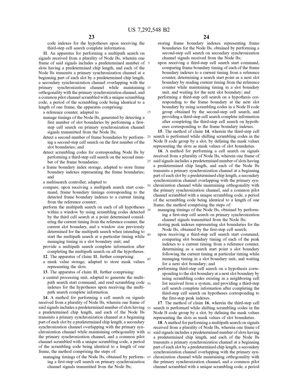
l f 921 I923 I917 I919 SEARCH PARAMETER f911 I913 (12) United States Patent Lim et a]. US 7,292,548 B2 I 925 f 915 MASK VALUE STORAGE RESULT
|
|
|
- Briana Johns
- 6 years ago
- Views:
Transcription
1 US B2 (12) United States Patent Lim et a]. (10) Patent N0.: (45) Date of Patent: US 7,292,548 B2 Nov. 6, 2007 (54) CELL SEARCH APPARATUS AND METHOD FOR SUPPORTING MULTISEARCH FUNCTIONS IN A MOBILE COMMUNICATION SYSTEM (75) Inventors: Chae-Man Lim, Seoul (KR); Yong-Serk Kim, SuWon-shi (KR) (73) Assignee: Samsung Electronics Co., Ltd., SuWon-Si (KR) (*) Notice: Subject to any disclaimer, the term of this patent is extended or adjusted under 35 U.S.C. 154(b) by 1094 days. (21) Appl. N0.: 10/420,913 (22) Filed: Apr. 23, 2003 (65) Prior Publication Data US 2003/ A1 Oct. 30, 2003 (30) Foreign Application Priority Data Apr. 24, 2002 (KR) (51) Int. Cl. H04Q 7/00 ( ) H04Q 7/20 ( ) H04B 7/216 ( ) (52) US. Cl /328; 370/335; 370/331; 455/436 (58) Field of Classi?cation Search /335, 370/328, 331, 342, 350, 333, 347; 455/422.1, 455/435.2, 435.3, , See application?le for complete search history. (56) References Cited FOREIGN PATENT DOCUMENTS EP /2002 Primary Examiner4Chris Kelley Assistant ExamineriXiao Qin (Vmcent) Lu (74) Attorney, Agent, or F irmiroylance, Abrams, Berdo & Goodman, LLP (57) ABSTRACT An apparatus and method manages timings of Node Bs by performing a?rst-step cell search on primary synchroniza tion channel signals transmitted from the Node Bs, and stores frame boundary indexes representing frame bound aries for the Node Bs by performing a second-step cell search on secondary synchronization channel signals received from the Node Bs. Upon receiving a third-step cell search start command, the apparatus and method compares frame boundary timing corresponding to each of the frame boundary indexes to a current timing from a reference timer, performs a third-step cell search on hypotheses correspond ing to the frame boundary indexes at a next slot boundary following the current timing by using scrambling codes in a Node B code group obtained by the second-step cell search, and provides a third-step cell search complete information after completing the third-step cell search on hypotheses corresponding to the frame boundary indexes. 18 Claims, 9 Drawing Sheets I917 MASK VALUE STORAGE I919 SEARCH PARAMETER STORAGE REFERENCE COUNTER I913 f 915 FRAME BOUNDARY INDEX STORAGE 4 MULTISEARCH > CONTROLLER f911 l f 921 I923 MULTIPATH SEARCHER RESULT _* INDEX STORAGE I 925 SCRAMBLING CODE INITIALIZATION VALUE STORAGE
2 U.S. Patent Nov. 6, 2007 Sheet 1 0f 9 US 7,292,548 B2 :lllllu " u in 65 N. 8 m I060 Iow >m<ozooww
3 U.S. Patent Nov. 6, 2007 Sheet 2 0f 9 US 7,292,548 B2 (0~M-1) (0~KN-1) r ~I i COUNTER i ; (0~(JKL-1)) g 5 ; "ED/gum)? 314 x KN xmodulo (KN) 316 i 1 I g g 5 SLOT COUNTER (0~M I) LOWER COUNTER (0~KN 1) ;
4

5 U.S. Patent Nov. 6, 2007 Sheet 4 0f 9 US 7,292,548 B2 SLOT COUNT 5&2 5 3 saiie COMMAN MEMORY 514; COUNT INOEx COUNTER STORED COUNT value COuNT SAVE COMMANO IO LOWER COUNT A FIRsT-sTEP searcher INITIAIIzATION SAVE COMMAND}, LOWER COUNT 516 HRSLSTEP FIRST-STEP FIRST-STEP OPERATION SEARCH COMMANO searcher M SIGNAL GENERATOR 51! 8 FIRsT-sTEP SEARCH OPERATION SIGNAL SEARCH RESULT J\ SECOND~STEP searcher INITIAIIzATION 1 LOWER COUNT/ 520 seco - EP " secono~setep L1 secono~step OPERATION JAM-OWL SEARCH B L S'GNALGENEHATOH siottiminginoex 5&2 SECOND-STEP SEARCHER INITIALIZATION SEARCH RESULT m\ THIRD-STEP SEARCHER INITIALIZATION COUNT 524 TH RD~STEP THIRg-sTEEP THIRD-STEP OPERATION SEARCH COMMAND SEA CH R \ SIGNAL GENERATOR MRDQEESIWCH 5%? 52C) THIRO-sTEP s ARCHER INITIAUZATION SEARCH RESULT START > J\ MuITIPATHsEARCHERINITIAuzATION COIINT 52s IIITIPATH MOLTIPATH hi MOITIPATH OPERATION SEARCH COMMAND searcher SIGNAL GENERATOR MULTIPATHP CH 51g MuLTIPATHs RCH OPERATION SIGNAL SEARCH RESULT START A FIRsT DEMODULATION FINGER INITIAIIzATION HEITIOHLNOO OEMOOuIATION OEMOOOIATION / FINGER UOMMAN FINGER #I \- OPERATION SIGNAL GENERATOR #1 DEMODULAHON I FIRsT DEMODULA ION FINGER OPERATION SIGNAL START POINT 534 secono DEMODULATION FINGER INITIAIIZATION I III / RFRIIRIR E DEMODULATION I OEMOOIILATION FINGER WW4 FINGER #2 OPERATION SIGNAL GENERATOR #2 DEMUDUWI 5&8 ; secono DE ODULATION FINGER INHIALIZATION STARTPOINT nth OEMOOOIATION FINGER INITIALIZATION COUNT / 540 nth FINGER OEMOOUIATION - OEMOOuLATION FINGER DE 8 EMP~ FINGER #n OPERATION SIGNAL GENERATOR #n DEMODULATION 542 TITH OEMOOuIATION FINGER OPERATION signai start POINT FIG.5
6
7
8
9 U.S. Patent Nov. 6, 2007 Sheet 8 0f 9 US 7,292,548 B2 A. ET: Iom<ww EEEKEE wwégm Q, A, am \ a ER E :; EIQEQW $30528 QUE wsee Egzsom v60; wo< o._.w
10

11 1 CELL SEARCH APPARATUS AND METHOD FOR SUPPORTING MULTISEARCH FUNCTIONS IN A MOBILE COMMUNICATION SYSTEM PRIORITY This application claims priority under 35 U.S.C. 119 to an application entitled Cell Search Apparatus and Method for Supporting Multisearch Function in a Mobile Commu nication System?led in the Korean Industrial Property Of?ce on Apr. 24, 2002 and assigned Serial No , the contents of Which are incorporated herein by reference. BACKGROUND OF THE INVENTION 1. Field of the Invention The present invention relates generally to a cell search apparatus and method in a mobile communication system, and in particular, to an apparatus and method for performing a multisearch operation on a plurality of cells to be searched. 2. Description of the Related Art In general, a mobile communication system is classi?ed into a synchronous system developed and used in the United States and an asynchronous system developed and used in Europe. With the rapid development of the mobile commu nication industry, there have been demands for a future mobile communication system Which can provide not only a voice service but also a multimedia service including data and image services. 3rd Generation Partnership Project (3GPP) has been standardizing both the synchronous future mobile communication system and the asynchronous future mobile communication system. The synchronous future mobile communication system is called a code division multiple access-2000 (CDMA-2000) system, and the asyn chronous future mobile communication system is called a Wideband-CDMA (W-CDMA) system. The W-CDMA mobile communication system comprises UMTS (Universal Mobile Telecommunications System) Terrestrial Radio Access Networks (U TRANs) that perform an asynchronous operation between Node Bs. Therefore, in order to identify the Node Bs, unique scrambling codes are assigned to the Node Bs. For example, if the number of cells, or Node Bs, constituting the UTRAN is 512, each of the 512 Node Bs is assigned its own unique scrambling code among 512 scram bling codes, for its identi?cation. Since a Node B transmits a signal With a scrambling code for its identi?cation, a user equipment (UE) must be able to identify a scrambling code for the Node B in order to normally receive a signal provided from the Node B. That is, in order to normally receive a signal provided from a Node B, a UE must determine a scrambling code of a signal received at the highest energy among signals received from its neighboring Node Bs, and such a process of determining a scrambling code is called cell search. The cell search is performed in various Ways according to circumstances, and includes (i) initial cell search for acquir ing pseudo noise (PN) code timing by a UE upon power on, (ii) multipath search for detecting a multipath signal com ponent of a received signal for rake demodulation While continuously maintaining the acquired PN code timing, (iii) neighbor cell search for searching target neighbor cells to Which the UE is to be handed off When the UE is located in a handoff region, and (iv) re-acquisition for re-acquiring PN code timing, Which Was lost When the UE selects a slotted mode in an idle state or Wakes up from a sleep state. US 7,292,548 B In the W-CDMA mobile communication system, a UE, as stated above, must perform cell search by measuring a phase of each of all scrambling codes that are assignable to Node Bs, i.e., 512 scrambling codes, in order to determine a scrambling code for a Node B to Which the UE itself belongs (hereinafter, referred to as a source Node B ). HoWever, such a cell search algorithm for determining phases of all scrambling codes for the Node Bs one by one requires a long cell search time. To solve this problem, a new multistep cell search algorithm has been proposed. The multistep cell search algorithm Will now be described below. Node Bs constituting the W-CDMA mobile communica tion system are assigned their own unique cell identi?cation codes, or scrambling codes, for identi?cation of the Node Bs. A UE identi?es the Node Bs With the assigned scram bling codes. It Will be assumed herein that the number of cells constituting the W-CDMA mobile communication sys tem is 512 and one cell exists in each Node B, so the number of Node Bs constituting the W-CDMA mobile communica tion system becomes 512. HoWever, the Node B may employ one or more cells. In this case, the 512 Node Bs are assigned their own unique scrambling codes, and a UE identi?es the Node Bs using the unique scrambling codes assigned to the Node Bs. Currently for a cell search, in order to search a source Node B, a UE must perform a cell search on each of the 512 Node Bs constituting the W-CDMA mobile communication system. Since performing a cell search on each of the 512 Node Bs constituting the W-CDMA mobile communication system is equivalent to measuring a phase of each of all the scrambling codes for the 512 Node Bs, the UE requires a large amount of time to perform the cell search. As a result, it is inef?cient to apply the existing cell search algorithm to each of the Node Bs constituting the W-CDMA mobile communication system. Therefore, the UE employs the multistep cell search algorithm. In order to realize the multistep cell search algorithm, a plurality of Node Bs, e.g., 512 Node Bs, belonging to the W-CDMA mobile commu nication system are divided into a predetermined number of groups, e.g., 64 groups Group#0 to Group#63. The divided 64 Node B groups are assigned their own unique group identi?cation codes, for identi?cation of the Node B groups. In addition, each Node B group includes 8 Node Bs, and the 8 Node Bs are assigned their own unique scrambling codes for spreading a common pilot channel (CPICH), so that the UE can search for its source Node B, using the assigned scrambling codes. The multistep cell search algorithm includes in the?rst step a search, in the second-step a cell search and in the third-step another cell search. In the?rst-step cell search process, a UE receives primary synchronization channel (P-SCH) signals transmitted from a Node B and acquires slot timing for a signal received at the highest power among the received P-SCH signals. In the second-step cell search process, the UE acquires slot synchronization based on the slot timing information acquired in the?rst-step cell search process, and then acquires frame synchronization and detects a Node B group to Which the UE belongs by receiving a secondary synchronization channel (S-SCH) transmitted from the Node B. In the third-step cell search process, the UE?nally searches for its source Node B using a scrambling code for the Node B by receiving a CPICH signal transmitted from the Node B based on the frame synchronization and Node B group information acquired in the second-step cell search process.
 and a common pilot channel (CPICH), for synchronization.")
12 3 The multistep cell search Will now be described With reference to FIG. 1. FIG. 1 illustrates an example of a structure of synchro nization channels in a general W-CDMA mobile communi cation system. Referring to FIG. 1, in the W-CDMA mobile communication system, a searcher in a UE uses a synchro nization channel (SCH) and a common pilot channel (CPICH), for synchronization. Node Bs transmit the CPICH using their own unique scrambling codes. A period of the scrambling code is equal to a one-frame length. In the W-CDMA mobile communication system having the chan nel structure illustrated in FIG. 1, as many Gold codes (not shown) having a period of as a one-frame length are used as the unique scrambling codes. Only M (I512) Gold codes among all available Gold codes are used. The SCH, a downlink channel used for cell search by the UE, comprises two subchannels primary SCH (P-SCH) and secondary SCH (S-SCH). Since each time slot of the P-SCH and S-SCH comprises 2,560 chips and 15 time slots constitute one radio frame, one radio frame, therefore, comprises 38,400 chips. Further, as illustrated in FIG. 1, the P-SCH and S-SCH are transmitted by N chips, i.e., 256 chips, amounting to 1/10 of the chips transmitted over one time slot, at the beginning of each time slot. In addition, as orthogonality is maintained between the P-SCH and the S-SCH, it is possible to overlap the two channels during transmission. The P-SCH, a channel over Which the 512 Node Bs constituting the W-CDMA mobile communication system transmit the same code, transmits a primary synchronization code (PSC) acp. Fur ther, the P-SCH transmits as much primary synchronization code as 1/10 period, i.e., 256 chips, ofa time slot at each time slot. The UE acquires the slot timing from a Node B by receiving a P-SCH signal transmitted from the Node B. The Node B transmits an S-SCH signal along With a P-SCH signal. If the 512 Node Bs constituting the W-CDMA mobile communication system are divided into 64 Node B groups, the S-SCH transmits a secondary synchronization code (SSC) acsi k, i.e., a Node B group identi?cation code to Which the Node B belongs. The secondary synchronization code is a l5-symbol sequence having a 256-chip length. In the secondary synchronization code, acsi k, i (:0, l,..., 63) represents the number of Node B groups, i.e., the number of scrambling code groups, Where k (:0, l,..., 14) represents a time slot number. Further, the secondary synchronization code is selected from 16 code groups having a 256-chip length. A sequence of the secondary synchronization code represents a code group to Which a downlink scrambling code for a corresponding Node B belongs. The code group further represents a group of codes for generating the Node B group identi?cation code. The secondary synchronization channel also transmits the secondary synchronization code using 1/10 period ofa time slot, i.e., using 256 chips, at each time slot. The UE detects a Node B group Which is its source Node B and synchronizes With a frame boundary by receiv ing a secondary synchronization channel signal transmitted from the Node B. The Node B group identi?cation code is used to determine a group to Which the Node B belongs. A comma-free code is typically used as the Node B group identi?cation code. The comma-free code comprises 64 codewords, and each codeword comprises 15 symbols. The 15 symbols are trans mitted every frame. HoWever, as mentioned above, values of the 15 symbols are mapped to one of the secondary syn chronization codes acsi k of acsi o, acsi l,..., acsi l5 before being transmitted. That is, as illustrated in FIG. 1, an ith secondary synchronization code corresponding to a symbol value i is transmitted every time slot. In addition, 64 US 7,292,548 B codewords of the comma-free code identify 64 code groups. The comma-free code is characterized such that the cyclic shift of each codeword is unique. Therefore, it is possible to acquire information on a code group, i.e., a Node B group, Where the UE belongs, and information on frame synchro nization by receiving a secondary synchronization channel signal for a period of several time slots, correlating second ary synchronization codes With a secondary channel signal for the period of several time slots, and performing a cyclic shift operation on each of the 64 codewords 15 times. The term frame synchronization means synchronization on timing or phase Within one period of a scrambling spreading code for a spread spectrum system. In the existing W-CDMA mobile communication system, one period of a spreading code and a length of a frame are both 10 ms, so this is called frame synchronization. After performing the?rst-step cell search process and the second-step cell search process, the UE can acquire infor mation on slot synchronization, Node B group identi?cation code and frame synchronization through the P-SCH and S-SCH. HoWever, since the UE cannot distinguish a scram bling code for its source Node B from 8 other Node B scrambling codes Within a code group based on the acquired Node B group identi?cation code, scrambling code synchro nization is not completed achieved yet. Therefore, the UE can identify a scrambling code to be used among the 8 scrambling codes by performing correlation on each of the 8 scrambling codes belonging to the code group for the CPICH via a third-step cell search process. The UE must periodically measure the strength of the signals transmitted from Node Bs neighboring its source Node B, in order to receive an optimal multipath signal from the Node B in a radio channel environment or a handolf situation. In this case, the UE acquires timing information of neighbor Node Bs by the multistep cell search algorithm or from the current Node B in service, receives CPICH from each of the corresponding Node Bs, and periodically per forms correlation on each of the received CPICH signals. Herein, a process of periodically measuring strength of signals from Node Bs neighboring a source Node B to acquire the timing information of the neighboring Node Bs Will be referred to as a multipath search in order to distinguish this process from the above-stated cell search process that is performed before the UE acquires timing of the neighbor Node Bs. Generally, the UE identi?es signals from Node Bs to Which it may probably move, by cell search, and continu ously manages the Node B signals through the multipath search. Further, the UE demodulates valid multipath signal components, i.e., valid multipath signals, among the signals received by the cell search and multipath search. In the case of the multipath search, the UE should be able to perform a high-speed search in order to promptly respond to an abrupt variation in channel conditions. The multipath search cal culates correlation values for all hypotheses at stated inter vals in a WindoW and then detects a plurality of correlation values Which are peak values and larger than or equal to a predetermined threshold value. Then, scrambling code tim ings having the detected correlation values become timings of multipath signal components. As stated above, the W-CDMA mobile communication system acquires scrambling code synchronization While continuously performing the third-step cell search. That is, a UE acquires time slot synchronization With P-SCH in the?rst-step cell search process, and acquires frame synchro nization and scrambling code group information, i.e., group information of its source Node B, With S-SCH in the

13 5 second-step cell search process. Finally, in the third-step cell search process, the UE detects a scrambling code assigned to a corresponding Node B among the 8 scrambling codes Within the determined scrambling code group by searching CPICH after the frame synchronization is achieved. In order to perform the third-step cell search process in this manner, the UE must determine reference timing for Where it Will start the?rst-step cell search process, and reference timing for Where it Will start the second-step cell search process after acquiring time slot synchronization as the?rst-step cell search process is completed. That is, in order to identify a scrambling code group and acquire frame synchronization in the second-step cell search process, the UE must determine reference timing Where it Will perform cyclic shift so as to determine a frame boundary from the number of cyclic shifts performed during codeword decoding. In addition, after acquiring scrambling code group information and frame synchronization information through the second-step cell search process, the UE must determine reference timing for Where it Will start the third-step cell search process. However, the UE must continuously perform such a cell search process for communication With Node Bs instead of performing the search only once at the initial cell search. Therefore, in order to calculate and manage a timing differ ence between a frame boundary of a signal currently demodulated by a UE and a frame boundary of signals received from the same Node B or different Node Bs, that may probably be demodulated later, a speci?ed criterion is required. That is, it must be possible to calculate a timing difference between a frame boundary of neighboring Node Bs, detected through a cell search process, and a frame boundary of other Node Bs, detected by the previous cell search. In the multipath search, a UE calculates a correlation for scrambling codes of Node Bs to Which the UE may probably move, and measures the strength of signals received from the Node Bs. HoWever, since the Node Bs have different frame boundaries, the UE must initialize scrambling codes to match phases of the scrambling codes of the Node Bs before calculating the correlation. Therefore, it is necessary to provide reference timing for initializing the scrambling codes of the Node Bs. Multipath signal compo nents determined to be valid by the cell search and the multipath search are assigned to a modulator or?nger of a UE, for demodulation. The demodulator of the UE must initialize a scrambling code of a corresponding Node B synchronized With a frame boundary of a corresponding multipath signal, and provide reference timing for initializ ing the scrambling code. A device for proving the reference timing is a reference counter, and the reference counter continuously performs a count operation at periods of 10 ms by managing timing by the time slot. The count unit is l/n chips, Where n is the number of oversamples. Amask operation or a slew operation is used to currently perform search on hypotheses to be searched When perform ing the third-step cell search or the multipath search. HoW ever, since the W-CDMA mobile communication system is an asynchronous mobile communication system, a UE has dif?culty in performing a cell search on a plurality of Node Bs While in motion, and information that the UE holds for the cell search is limited. Particularly, the UE cannot store all mask values chip by chip (or in a chip unit) Within 10 ms Which is a unit of managing the reference timing. In addi tion, When a UE is designed to usually start the third-step cell search or the multistep search at a frame boundary, the UE should always Wait for a frame boundary, suffering a loss in terms of demodulation timing, i.e., search rate. That is, the multipath search increases demodulation performance by US 7,292,548 B demodulating and combining signals received through mul tiple paths, and When the UE usually starts the multipath search at a frame boundary, a delay occurs in actual com bining due to the Waiting time, causing a decrease in demodulation performance. Therefore, the UE suffers a loss in terms of demodulation timing. Therefore, in general, a central processing unit (CPU) of the UE detects current timing by reading a current index value of the reference counter, determines an actual point of time Where a searcher Will operate, based on the detected current timing, and then sets a mask value for a phase of a corresponding scrambling code and activates the searcher. As described above, in the third-step cell search and the multipath search, the CPU plays a part in determining an operation point of a searcher, and activates the searcher at the determined point of time. Of course, if the CPU?xes an operation point to a speci?c point instead of variably deter mining the operation point according to circumstances, the searcher Will be usually activated at the?xed speci?c point of time. HoWever, When cell search is performed in a channel environment, the search rate serves as an important parameter in the signal demodulation performance. In this case, the search rate must be high so that the UE can adaptively cope With a variation in the radio channel envi ronment. HoWever, the search rate is determined according to a plurality of parameters, such as hardware complexity, CPU speed, and software task scheduling. Therefore, in the case Where there exists N search targets, in order to reduce a software load, it is possible to Write by hardware all parameters related to the N search targets at once, thereby enabling a corresponding hardware to sequentially search the N search targets. The operation of searching by hardware for a plurality of search targets in a lump Will be referred to as a multisearch operation. In the W-CDMA mobile communication system, a counter operating in a frame unit (:10 ms), i.e., a reference counter, is used to continuously calculate a timing difference between Node Bs, i.e., a difference between frame bound aries. Herein, the reference counter Will be referred to as an index counter, since an output of the reference counter is used as reference timing for a cell searcher, a multipath searcher and a multipath signal demodulator. The index counter continuously operates, after being initialized by a CPU upon powering a UE. If a resolution of a searcher is l/k chip, the index counter should also have a resolution of over l/k chip. In the 3GPP speci?cation, a length L of one frame is L:38,400 chips, the number M of time slots constituting one frame is MIl 5, and a length N of one time slot is N:2,560 chips. The length L of one frame becomes a period of one frame, and the length N of one time slot becomes a period of one time slot. A resolution of the searcher represents accuracy of the search, and is used to search for a more accurate synchronization point. Therefore, the minimum unit is 1 chip. In order to detect an accurate synchronization point, it is preferable to check a plurality of hypotheses or sampling points per chip and select an optimal point among the points. FIGS. 2 and 3 illustrate different examples of a general index counter. Referring?rst to FIG. 2, an index counter 210 comprises a slot counter 212 for counting time slots constituting one frame and a lower counter 214 for counting the number, K><N l, of chips corresponding to a length of a predeter mined number of time slots. A count value by the slot counter 212 ranges from 0 to M-l, and a count value by the lower counter 214 ranges from 0 to K><N l. As stated above, in the W-CDMA mobile communication system, one frame
 of N, i.e., counts the number N of chips constituting one time slot.")
14 7 comprises 15 time slots. The M, in this case, becomes 15. Further, in the W-CDMA mobile communication system, one time slot comprises 2,560 chips. The N, in this case, becomes 2,560. The lower counter 214 is reset to 0, When its count value becomes K><N. The slot counter 212 increases its count value by 1, each time the lower counter 214 counts a multiple (KxN) of N, i.e., counts the number N of chips constituting one time slot. The slot counter 212 is reset to 0, When the number of time slots constituting one frame is counted, i.e., the count value becomes M. Referring now to FIG. 3, an index counter 310 has a structure for deriving count values of a slot counter 314 and a lower counter 316, using a single counter. The slot count 314 and the lower count 316 of FIG. 3 are substantially identical in function to the slot counter 212 and the lower counter 214 of FIG. 2, although they are represented by different reference numerals. A counter 312 constituting the index counter 310 counts from 0 to J><K><L 1, Where I is an integer (1:1, 2, 3,... ). Count values ofthe slot counter 314 and the lower counter 316 are derived from a value counted by the index counter 310 in accordance With Equation (1). Slot count value:[(count value)/(k><n)j modulo M LoWer count value:(count value) modulo In Equation (1), [x] represents a maximum integer smaller than a given value x, and a modulo b represents a remainder obtained by dividing a by b. Since the index counters 210 and 310 of FIGS. 2 and 3, respectively, operate at periods of a frame length, frame boundary points of all asynchronous cells (or Node Bs) are mapped to either speci?c count values of the slot counter 212 and the lower counter 214 in the index counter 210, or speci?c count values of the slot counter 314 and the lower counter 316 in the index counter 310. When the frame boundary point of the index counter 210 or 310 is de?ned as a reference point, a position of a frame boundary point of each asynchronous cell is called a frame timing index of the corresponding cell. Therefore, if a frame timing index of each cell is given, it is possible to calculate an offset between the cells. Here, the term o? set means a difference between frame boundary points of the asynchronous cells. In addition, it is possible to count a time slot length With the lower counter 214 or 316 of the index counters 210 and 310, respectively. Therefore, slot boundary points of all asynchronous cells can be mapped to a speci?c count value of the lower counter 214 or 316 in the index counters 210 and 310. When a slot boundary point of the lower counter 214 or 316 is de?ned as a reference point, a position ofa slot boundary point of each asynchronous cell is called a slot timing index of the corresponding cell. Therefore, if a slot timing index of each cell is given, it is possible to calculate an offset between slot boundary points of the cells. FIG. 4 illustrates an example of a timing relationship between an index counter and asynchronous cells. Speci? cally, FIG. 4 illustrates a timing relationship between two asynchronous cells Cell_A and Cell_B, by Way of example. Referring to FIG. 4, an index counter s frame boundary 410, Which is a reference point for determining a frame-boundary of the cells, may correspond to a count start point of the index counters 210 and 310. The slot counter 212 or 314 of the index counters 210 and 310 counts index counter s slot boundaries 412 up to M-1 after being reset to 0 at the index counter s frame boundary 410. The index counter s slot boundary 412, Which is a reference point for determining slot boundaries in one frame, may correspond to a count start point of the lower counter 214 or 316 of the index counters US 7,292,548 B2 Equation (1) and 310. The lower counter 214 or 316 restarts counting, after being reset to 0 at the index counter s slot boundary 412. A Cell A s slot boundary 426 is a point Where the?rst-step cell search process is completed after the?rst-step cell search process is performed at a given time point T1:0. TIIO means that a count value of the lower counter 214 or 316 is 0. In this case, the?rst-step cell search process is performed at any one of the index counter s slot boundaries 412. If the Cell A s slot boundary 426 is determined, a Cell A s slot timing index 430 is determined by an offset between the Cell A s slot boundary 426 and the give time T1:0. For example, the Cell A s slot timing index 430 is determined by a count value of the lower counter 214 or 316 at the Cell A s slot boundary 426. A Cell B s slot boundary 424 and a Cell B s slot timing index 428 are determined in the same process as used for the Cell A s slot boundary 426 and the CellA s slot timing index 430. The Cell A s slot boundary 426 and the Cell B s slot boundary 424 correspond to one of count values 0 to NK-l, counted by the lower counter 214 or 316. An o? set between the Cell A s slot boundary 426 and the Cell B s slot boundary 424 is de?ned as a slot offset 432. ACell A s frame boundary 414 is determined by the number of cyclic shifts of codewords for a code group having a maximum correla tion energy by performing the second-step cell search pro cess at the Cell A s timing index 430. That is, a point spaced apart from the start point or the Cell A s slot timing index 430 of the second-step cell search process by a length of as many slots as the number x of cyclic shifts becomes the Cell A s frame boundary 414. A Cell A s frame timing index 418 is de?ned as a value counted by the slot counter 212 and the lower counter 214, or the slot counter 314 and the lower counter 316 at the Cell A s frame boundary 414. A Cell B s frame boundary 416 and a Cell B s frame timing index 420 are determined using the same process that Was used for the Cell A s frame boundary 414 and the Cell A s frame timing index 418. The Cell A s frame boundary 414 and the Cell B s frame boundary 416 are determined by one of count values 0 to M-1, counted by the slot counter 212 or 314, and the Cell A s slot boundary 426 or the Cell B s slot boundary 424. An o? set between the Cell A s frame boundary 414 and the Cell B s frame boundary 416 is de?ned as a frame offset 422. FIG. 5 illustrates an example of a cell search apparatus for a UE in a general W-CDMA mobile communication system. Referring to FIG. 5, a controller 510 controls an overall operation for cell search. Here, the controller 510 is identical in operation to the above-stated CPU. An index counter 514, having the structure illustrated in FIGS. 2 and 3, performs a counting operation stated above. A memory 512 stores a value counted by the index counter 514 in response to a save command from the exterior. The save command is divided into a lower count save command from a?rst-step searcher 518, a slot count save command from a second-step searcher 522, and a count save command from the controller 510. The memory 512 provides the controller 510 With the stored count value in response to the count save command from the exterior. A?rst-step operation signal generator 516 generates a?rst-step search operation signal based on a count value provided from the index counter 514 in response to a?rst-step search command received from the controller 510. A?rst-step searcher 518 is initialized in response to an initialization command from the controller 510, and per forms a?rst-step search operation on a received signal in response to the?rst-step search operation signal from the

15 ?rst-step operation signal generator 516. After completing the?rst-step search operation, the?rst-step searcher 518 provides the search result by the?rst-step search operation to the controller 510. A second-step operation signal generator 520 generates a second-step search operation signal based on the count value provided from the index counter 514 in response to a second-step search command and a slot timing index by the?rst-step search operation, received from the controller 510. A second-step searcher 522 is initialized in response to an initialization command from the controller 510, and per forms a second-step search operation on the received signal in response to the second-step search operation signal from the second-step operation signal generator 520. The received signal indicates a multipath signal, Which is determined as a valid signal by the?rst-step search. After completing the second-step search operation, the second-step searcher 522 provides the search result by the second-step search opera tion to the controller 510. Meanwhile, the second-step searcher 522 commands the memory 512 to store a slot count value counted by the index counter 514, at a speci?c time point during the second-step search operation. For example, the second-step searcher 522 commands the memory 512 to store the slot count value counted by the index counter 514, at a point Where the second-step search operation is started or a point Where the second-step search operation is completed. A third-step operation signal generator 524 generates a third-step search operation signal based on the count value provided from the index counter 514 in response to a third-step search command and the search result by the second-step search operation or a third-step search start point by a hypothesis for the second-step search result, received from the controller 510. A third-step searcher 526 is initialized in response to an initialization command from the controller 510, and performs a third-step search opera tion on the received signal in response to the third-step search operation signal from the third-step operation signal generator 524. The received signal means a multipath signal Which is determined as a valid signal. After completing the third-step search operation, the third-step searcher 526 pro vides the search result by the third-step search operation to the controller 510. The controller 510 can determine a scrambling code for a target cell to be searched based on the search result from the third-step searcher 526. A multipath operation signal generator 528 generates a multipath search operation signal based on the count value provided from the index counter 514 in response to a multipath search command and a multipath search start point, received from the controller 510. A multipath searcher 530 is initialized in response to an initialization command from the controller 510, and performs a multipath search operation on the received signal in response to the multipath search operation signal from the multipath operational signal generator 528. The received signal indicates a multipath signal, Which is determined as a valid signal. After com pleting the multipath search operation, the multipath searcher 530 provides the search result by the multipath search operation to the controller 510. A plurality of demodulation?nger operation signal gen erators 532, 536 and 540 each generate a demodulation?nger operation signal based on the count value provided from the index counter 514 in response to a?nger demodu lation command and a demodulation start point, received from the controller 510. The demodulation start point is a frame timing index indicating a frame boundary based on a scrambling code of a corresponding multipath signal to be US 7,292,548 B demodulated. A plurality of demodulation?ngers 534, 538 and 542 each are initialized in response to a corresponding initialization command from the controller 510, and perform demodulation on the received signal in response to the demodulation?nger operation signals from the demodula tion?nger operation signal generators 532, 536 and 540. The received signal indicates a valid multipath signal, and the scrambling operation includes an initialization operation on the scrambling code. HoWever, the above-stated general cell searcher sequen tially searches all search targets from the?rst search target to the last search target in the?rst-step cell search process, second-step cell search process, third-step cell search pro cess and multipath search process, instead of multi-search ing all the search targets in a lump. That is, a CPU Writes search parameters for the?rst search target in the cell searcher. Thereafter, the cell searcher informs the CPU of a completed search on the?rst search target. The CPU then reads the completed search result provided by the cell searcher. Thereafter, as described in conjunction With the?rst search target, even for the next search target, the CPU Writes search parameters for the corresponding search target in the cell searcher. Thereafter, the cell searcher informs the CPU of a completed search on the corresponding search target. The CPU then reads the completed search result by the cell searcher. In this manner, the CPU repeatedly per forms a Write operation for cell search and/or a read opera tion for reading search results, each time a search on each of all the search targets is completed. HoWever, since the CPU performs a plurality of software tasks While controlling the overall operation of a UE, the repetition of the Write and read operations for a cell search serves as a heavy load in operation of the CPU. SUMMARY OF THE INVENTION It is, therefore, an object of the present invention to provide a cell search apparatus and method for supporting a multisearch function in a mobile communication system. To achieve the above and other objects, the present invention provides an apparatus for performing a cell search on signals received from a plurality of Node Bs, Wherein one frame of the signals includes a predetermined number of slots having a predetermined chip length, and each of the Node Bs transmits a primary synchronization channel at a beginning part of each slot by a predetermined chip length, a secondary synchronization channel overlapping With the primary synchronization channel While maintaining orthogonality With the primary synchronization channel, and a common pilot channel scrambled With a unique scrambling code, a period of the scrambling code being identical to a length of one frame. The apparatus comprises a reference counter adapted to manage timings of the Node Bs, the timing being obtained by performing a?rst-step cell search on primary synchronization channel signals transmitted from the Node Bs; a frame boundary index storage adapted to store frame boundary indexes representing frame bound aries for the Node Bs, the frame boundaries are obtained by performing a second-step cell search on secondary synchro nization channel signals received from the Node Bs; and a multisearch controller adapted to compare, upon receiving a third-step cell search start command, frame boundary timing of each of the frame boundary indexes to a current timing from the reference counter, perform third-step cell search on hypotheses corresponding to the frame boundary indexes at a next slot boundary following the current timing by using scrambling codes in a Node B code group obtained by the

16 11 second-step cell search, and provide third-step cell search complete information after completing the third-step cell search on hypotheses corresponding to the frame boundary indexes. To achieve the above and other objects, the present invention provides an apparatus for performing a cell search on signals received from a plurality of Node Bs, Wherein one frame of the signals includes a predetermined number of slots having a predetermined chip length, and each of the Node Bs transmits a primary synchronization channel at a beginning part of each slot by a predetermined chip length, a secondary synchronization channel overlapping With the primary synchronization channel While maintaining orthogonality With the primary synchronization channel, and a common pilot channel scrambled With a unique scrambling code, a period of the scrambling code being identical to a length of one frame The apparatus comprises a reference counter adapted to manage timings of the Node Bs, the timings being obtained by performing a?rst-step cell search on primary synchronization channel signals transmitted from the Node Bs; a?rst-step peak index storage adapted to store peak indexes representing slot boundaries for the Node Bs, the slot boundaries being obtained by the?rst-step cell search; and a multisearch controller adapted to compare, upon receiving a third-step cell search start command, slot boundary timing of each of the peak indexes to a current timing from the reference counter, perform a third-step cell search on hypotheses corresponding to the slot boundaries at a next slot boundary following the current timing by using scrambling codes existing in a neighboring cell list received from a system, and provid a third-step cell search complete information after completing the third-step cell search on hypotheses corresponding to the peak indexes. To achieve the above and other objects, the present invention provides an apparatus for performing a multipath search on signals received from a plurality of Node Bs, Wherein one frame of the signals includes a predetermined number of slots having a predetermined chip length, and each of the Node Bs transmits a primary synchronization channel at a beginning part of each slot by a predetermined chip length, a secondary synchronization channel overlap ping With the primary synchronization channel While main taining orthogonality With the primary synchronization channel, and a common pilot channel scrambled With a unique scrambling code, a period of the scrambling code being identical to a length of one frame. The apparatus comprises a reference counter adapted to manage timings of the Node Bs, generated by detecting a?rst number of slot boundaries by performing a?rst-step cell search on primary synchronization channel signals transmitted from the Node Bs, detect a second number of frame boundaries by per forming a second-step cell search on the?rst number of the slot boundaries, and detect scrambling codes for correspond ing Node Bs by performing a third-step cell search on the second number of the frame boundaries; a frame boundary index storage adapted to store frame boundary indexes representing the frame boundaries; and a multisearch con troller adapted to compare, upon receiving a multipath search start command, frame boundary timings correspond ing to the detected frame boundary indexes to a current timing from the reference counter, perform multipath search on each of all hypotheses Within a WindoW by using scram bling codes detected by the third cell search at a point determined considering the current timing from the refer ence counter, the current slot boundary, and a WindoW size previously determined for the multipath search When intend ing to start the multipath search at a particular timing While US 7,292,548 B managing timing in a slot boundary unit, and provide a multipath search complete information after completing the multipath search on all the hypotheses. To achieve the above and other objects, the present invention provides a method for performing a cell search on signals received from a plurality of Node Bs, Wherein one frame of the signals includes a predetermined number of slots having a predetermined chip length, and each of the Node Bs transmits a primary synchronization channel at a beginning part of each slot by a predetermined chip length, a secondary synchronization channel overlapping With the primary synchronization channel While maintaining orthogonality With the primary synchronization channel, and a common pilot channel scrambled With a unique scrambling code, a period of the scrambling code being identical to a length of one frame. The method comprises the steps of managing timings of the Node Bs, obtained by performing a?rst-step cell search on primary synchronization channel signals transmitted from the Node Bs; storing frame bound ary indexes representing frame boundaries for the Node Bs, obtained by performing a second-step cell search on sec ondary synchronization channel signals received from the Node Bs; upon receiving a third-step cell search start command, comparing frame boundary timing of each of the frame boundary indexes to a current timing from a reference counter, determining a search start point as a next slot boundary by reading current timing from the reference counter While maintaining timing in a slot boundary unit, and Waiting for the next slot boundary; and performing a third-step cell search on a hypothesis corresponding to the frame boundary at the next slot boundary by using scram bling codes in a Node B code group obtained by the second-step cell search, and providing a third-step cell search complete information after completing the third-step cell search on hypotheses corresponding to the frame bound ary indexes. To achieve the above and other objects, the present invention provides a method for performing a cell search on signals received from a plurality of Node Bs, Wherein one frame of the signals includes a predetermined number of slots having a predetermined chip length, and each of the Node Bs transmits a primary synchronization channel at a beginning part of each slot by a predetermined chip length, a secondary synchronization channel overlapping With the primary synchronization channel While maintaining orthogonality With the primary synchronization channel, and a common pilot channel scrambled With a unique scrambling code, a period of the scrambling code being identical to a length of one frame. The method comprises the steps of managing timings of the Node Bs, obtained by performing a?rst-step cell search on primary synchronization channel signals transmitted from the Node Bs; storing peak indexes representing slot boundaries for the Node Bs, obtained by the?rst-step cell search; upon receiving a third-step cell search start command, comparing slot boundary timing of each of the peak indexes to a current timing from a reference counter, determining as a search start point a slot boundary following the current timing at particular timing While managing timing in a slot boundary unit, and Waiting for a next slot boundary; and performing a third-step cell search on a hypothesis corresponding to the slot boundary at a next slot boundary by using scrambling codes existing in a neighboring cell list received from a system, and providing a third-step cell search complete information after complet ing the third- step cell search on hypotheses corresponding to the?rst-step peak indexes.

17 13 To achieve the above and other objects, the present invention provides a method for performing a multipath search on signals received from a plurality of Node Bs, Wherein one frame of the signals includes a predetermined number of slots having a predetermined chip length, and each of the Node Bs transmits a primary synchronization channel at a beginning part of each slot by a predetermined chip length, a secondary synchronization channel overlap ping With the primary synchronization channel While main taining orthogonality With the primary synchronization channel, and a common pilot channel scrambled With a unique scrambling code, a period of the scrambling code being identical to a length of one frame. The method comprising the steps of managing timings of the Node Bs, generated by detecting a?rst number of slot boundaries by performing a?rst-step cell search on primary synchroniza tion channel signals transmitted from the Node Bs, detecting a second number of frame boundaries by performing sec ond-step cell search on the?rst number of the slot bound aries, and detecting scrambling codes for corresponding Node Bs by performing a third-step cell search on the second number of the frame boundaries; storing frame boundary indexes representing the frame boundaries; and upon receiv ing a multipath search start command, comparing frame boundary timings corresponding to the detected frame boundary indexes to a current timing from a reference counter, performing the multipath search on each of all hypotheses Within a WindoW by using scrambling codes detected by the third cell search at a point determined considering the slot boundary following the current timing and a WindoW size previously determined for the multipath search at particular timing While managing timing in a slot boundary unit, and providing a multipath search complete information after completing the multipath search on all the hypotheses. BRIEF DESCRIPTION OF THE DRAWINGS The above and other objects, features and advantages of the present invention Will become more apparent from the following detailed description When taken in conjunction With the accompanying drawings in Which: FIG. 1 illustrates an example of a structure of synchro nization channels in a general W-CDMA mobile communi cation system; FIGS. 2 and 3 illustrate different examples of a general index counter; FIG. 4 illustrates an example of a timing relationship between an index counter and asynchronous cells; FIG. 5 illustrates an example of a cell search apparatus for a UE in a general W-CDMA mobile communication system; FIG. 6 is a block diagram illustrating an example of a structure of a cell searcher for supporting a multisearch function according to an embodiment of the present inven tion; FIG. 7 is a diagram illustrating an example of an operation timing Where the cell searcher of FIG. 6 performs a?rst/ second/third-step cell search; FIG. 8 is a diagram illustrating an example of an operation timing Where the cell searcher of FIG. 6 performs?rst/third step cell search; FIG. 9 is a block diagram illustrating an example of a structure of a cell searcher for supporting a multisearch function according to another embodiment of the present invention; and US 7,292,548 B FIG. 10 is a diagram illustrating an example of an operation timing Where a cell searcher of FIG. 9 performs multipath search according to another embodiment of the present invention. DETAILED DESCRIPTION OF THE PREFERRED EMBODIMENT Several embodiments of the present invention Will now be described in detail With reference to the accompanying drawings. In the drawings, the same or similar elements are denoted by the same reference numerals. A detailed descrip tion of known functions and con?gurations have been omit ted for conciseness. A Wideband-code division multiple access (W-CDMA) mobile communication system performs multistep cell search including?rst to third-step cell search processes. Herein, an initial cell search that is performed as a user equipment (UE) is powered on Will not be considered in describing cell search. Since the initial cell search is not considered, the second-step cell search process is performed on all of N peak values searched in the?rst-step cell search process. In the?rst-step cell search process, a UE receives primary synchronization channel (P-SCH) signals transmit ted from a plurality of Node Bs and searches for the slot timings of signals having an energy value larger than a predetermined threshold value from among the received signals having a peak value. If the number of P-SCH signals having a peak value larger than the threshold value among the N peak values is K, the second-step cell search process is performed to search for slot timings of the K P-SCH signals having the peak value. In the second-step cell search process, the UE receives secondary synchronization channel (S-SCH) signals trans mitted from Node Bs in accordance With the slot timings searched in the?rst-step cell search process, and detects frame synchronization and a Node B group to Which the UE itself belongs. LikeWise, even in the second-step cell search process, the UE receives the S-SCH signals in synchro nously With the K slot timings and detects frame synchro nization, i.e., frame boundary, for the signals having an energy value larger than a predetermined threshold value. If the number of signals having a peak value larger than the threshold value among the S-SCH signals that are synchro nized With the K slot timings is M, the UE detects frame boundaries and Node B group codes for the M signals, and then performs a third-step cell search process in accordance With the detected M frame boundaries. In the third-step cell search step, the UE receives common pilot channel (CPICH) signals transmitted from Node Bs in accordance With the M frame boundaries and Node B group codes, i.e., Node B group information, detected in the second-step cell search process, and?nally searches for its source Node B using a scrambling code for the corresponding Node B. Since M frame boundaries and Node B group information are detected in the second-step cell search process, the UE must?nally determine, in the third-step cell search process, a scrambling code in use among the 8 scrambling codes corresponding to the Node B group, for one hypothesis. NoW, With reference to FIG. 6, a description Will made of an operation of the cell searcher in the case Where the?rst-step cell search, second-step cell search and third-step cell search are sequentially performed. Herein, a cell search in Which the?rst-step cell search, second-step cell search and third-step cell search are sequentially performed Will be referred to as?rst/second/third-step cell search.
 (not shown) that manages software task scheduling for overall control of a UE, the UE?")
18 15 FIG. 6 is a block diagram illustrating an example of a structure of a cell searcher for supporting a multisearch function according to an embodiment of the present inven tion. Referring to FIG. 6, in order to perform a multisearch operation in cell search Without a central processing unit (CPU) (not shown) that manages software task scheduling for overall control of a UE, the UE?rst searches for a?rst- step peak index indicating K peak values detected in the?rst-step cell search. In the case of the?rst/second/third-step cell search, a peak index value searched in the?rst-step cell search is not stored in a?rst-step peak index storage 615. Further, in order to multisearch a third-step cell search for M hypotheses detected in the second-step cell search, the CPU stores frame boundary index for each of the M hypotheses in a frame boundary index storage 617, and stores an initial value of a?rst scrambling code in a Node B group to Which the M hypotheses belong, in a scrambling code initial value storage 627. An initial value of a?rst scrambling code in the Node B group is stored because if an initial value of a?rst scrambling code belonging to a corresponding Node B group is given, it is possible to determine initial values of scrambling codes for other Node Bs in the corresponding Node B group. This is performed because initial values of other scrambling codes are set to values determined by applying predetermined unique offsets to the initial value of the?rst scrambling code. By storing only the initial value of the?rst scrambling code, it is possible to increase memory ef?ciency. A reference counter 613, Which is a counter for providing reference timing for scrambling code initialization, provides CPICH signal timing, i.e., scrambling code timing, received from a reference Node B by Which the UE is currently serviced. The reference counter 613 counts scrambling code timing chip by chip, and is reset at periods of a time slot. Since the proposed cell search process is based on a slot boundary, a mask value storage 619 stores preferably only 15 mask values obtained by segmenting one radio frame by a time slot. A search parameter storage 621 stores search parameters for the cell search, such as the number of synchronization accumulations. After storing all values for the cell search, the CPU provides a third-step cell search start command to a multi search controller 611. The multisearch controller 611 is enabled in response to the third-step cell search start com mand. The multisearch controller 611, after being enabled, reads a?rst frame boundary index from the frame boundary index storage 617 in order to perform a third-step cell search on a?rst hypothesis among the M hypotheses. The multi search controller 611 compares frame boundary timing information corresponding to the read?rst frame boundary index to the reference timing provided chip by chip from the reference counter 613 to check in a time slot unit a timing difference between a current position and a position corre sponding to the?rst frame boundary index. Therefore, in order to perform the third-step cell search at the next time slot boundary, the multisearch controller 611 instructs the mask value storage 619 to Write a mask value corresponding to the next time slot in a third-step cell searcher 623. Further, the multisearch controller 611 instructs the scrambling code initial value storage 627 to Write a scrambling code initial value for each of the 8 Node Bs in a Node B group corresponding to the?rst hypothesis in the third-step cell searcher 623. The third- step cell searcher 623 then performs a third-step cell search based on the mask value corresponding to the?rst hypothesis and the 8 scrambling code initial values, and provides to a result storage 625 a maximum correlation US 7,292,548 B value among the correlation values for the 8 scrambling code initial values generated as a result of the third-step cell search, and a scrambling code index of a scrambling code initial value corresponding to the maximum correlation value. The result storage 625 then stores the maximum correlation value for the?rst hypothesis and the scrambling code initial value corresponding to the maximum correlation value, provided from the third-step cell searcher 623. In the same Way, for the other hypothesis, the multisearch control ler 611 Writes a corresponding mask value and 8 scrambling code initial values in the corresponding Node B group in the third-step cell searcher 623, and the third-step cell searcher 623 then performs the third-step cell search based on the mask value and the 8 scrambling code initial values in the corresponding Node B group. When the third-step cell searcher 623 completes the cell search for each of the M hypotheses in this manner, the multisearch controller 611 provides a third-step cell search complete signal, or an interrupt signal, indicating completed cell search for the M hypotheses to the CPU. Upon receiving the interrupt signal provided from the multisearch controller 611, the CPU simultaneously reads the third-step cell search results stored in the result storage 625, thereby minimizing a load on the CPU. FIG. 7 is a diagram illustrating an example of operation timing Where the cell searcher of FIG. 6 performs a?rst/ second/third-step cell search according to an embodiment of the invention. The cell searcher described in conjunction With FIG. 6 performs third-step cell search on M hypotheses stored in the frame boundary index storage 617, i.e., frame boundaries detected in the second-step cell search process. Operation timing Where the third-step cell search is per formed on a particular hypothesis among the M hypotheses Will be described below With reference to FIG. 7. If the CPU provides a third-step cell search start com mand to the multisearch controller 611, the multisearch controller 611 is enabled in response to the third-step cell search command. The multisearch controller 611, after being enabled, compares frame boundary timing corresponding to a particular frame boundary index among M frame boundary indexes With current reference timing provided from the reference counter 613. In FIG. 7, the frame boundary timing corresponding to the particular frame boundary index is represented by t1, and the current reference timing provided from the reference counter 613 is represented by t2. For example, as a result of reading reference timing from the reference counter 613 in order to start the search While checking the timing slot by slot on the basis of the frame boundary timing t1, the multisearch controller 611 deter mines that the current timing is t2. Therefore, the multi search controller 611 determines to start the search at timing t3, detecting that the next slot boundary nearest to the time point t2 is t3. In this case, the multisearch controller 611 instructs the mask value storage 619 to set a mask value corresponding to the slot boundary t3 While Waiting for the slot boundary t3 nearest to the point t2. Accordingly, at the slot boundary t3, the multisearch controller 611 provides a third-step cell search command for the particular hypothesis to the third-step cell searcher 623, and the third-step cell searcher 623 then performs the third-step cell search on the particular hypothesis. When the third-step cell search is completed on all the M hypotheses in this manner, the multisearch controller 611 provides an interrupt signal indi cating completion of the third-step cell search to the CPU at a timing point t4 Where the third-step cell search has been completed.

19 17 Next, an operation of the cell searcher in the case Where only the?rst-step cell search and the third-step cell search are performed Will be described below With reference to FIG. 6. Herein, a cell search in Which the third-step cell search is performed immediately after the?rst cell search Will be referred to as a?rst/third-step cell search. Since the?rst/third-step cell search occurs in the case Where a neigh boring cell list is given, all scrambling codes existing in the neighboring cell list must be stored in order to normally perform the cell search. In the present invention, it Will be assumed that a maximum of 32 neighboring cells exist in the neighboring cell list. Corresponding initial values must be stored in the scrambling code initial value storage 627. Assuming that the third-step cell searcher 623 includes 16 correlators therein, When?rst setting initial parameters, the third-step cell searcher 623 can set 16 scrambling code initial values. After completing the search on these values, the third-step cell searcher 623 sets the remaining 16 scram bling code initial values, and then completes the search on a particular slot boundary. The?rst/third-step cell search must preferably perform a hypothesis test on 15 slot bound aries in order to detect a frame boundary for K peak values larger than a predetermined threshold value, i.e., K hypoth eses, detected in the?rst-step cell search. That is, as described above, the CPU stores the scram bling code initial values in the scrambling code initial value storage 627, and also stores?rst-step peak indexes repre senting the K peak values in the?rst-step peak index storage 615. When performing the?rst/third-step cell search, the cell searcher of FIG. 6 does not store separate frame boundary indexes in the frame boundary index storage 617. After storing all the values for the?rst/third-step cell search, the CPU provides a third-step cell search start command to the multisearch controller 611, and the multisearch control ler 611 is enabled in response to the third-step cell search start command. The multisearch controller 611, as it is enabled, receives reference timing provided from the refer ence counter 613 and gives a test in a?rst peak index, i.e., a?rst hypothesis, among K peak indexes stored in the?rst-step peak index storage 615. The multisearch controller 611 compares a slot boundary corresponding to the read?rst peak index With reference timing provided from the refer ence counter 613, and determines a timing difference between a current position and a position corresponding to the?rst slot boundary index by a time slot. In order to perform the third-step cell search at the next time slot boundary, the multisearch controller 611 instructs the mask value controller 619 to Write a mask value corresponding to the?rst slot boundary in the third-step cell searcher 623 at the next time slot. Further, the multisearch controller 611 instructs the scrambling code initial value storage 627 to?rst Write the 16 scrambling code initial values among the stored initial values in the third-step cell searcher 623. Thereafter, the multisearch controller 611 performs the search on the?rst slot boundary in the same Way using the remaining 16 scrambling codes. In this case, it is necessary to memorize a value of a slot counter in a reference counter for a position Where the initial search is started. This value is recorded in the result storage 625. Therefore, When performing the search on the?rst slot boundary at a particular time, it is necessary to check how many slots have elapsed from an initial search point and to read a corresponding mask value from the mask value storage 619. The 15 slot boundaries should be checked for all the cases Where a phase difference between a reference slot Where the initial search is started and each of the slot boundaries becomes 0 to 14 slots. A mask value must be read considering the phase difference. US 7,292,548 B The reason for checking the phase difference is to determine a position Where the peak value searched in the?rst-step cell search is located among the 15 slot boundaries. The third-step cell searcher 623 then performs the third step cell search, using the mask value corresponding to the?rst hypothesis and the 32 scrambling code initial values. The third-step cell searcher 623 checks a slot boundary for each of the 32 scrambling code initial values for the?rst hypothesis, and as a result of the check, provides the result storage 625 With a maximum correlation value among correlation values for each of the 32 scrambling code initial values, a scrambling code index of a scrambling code corresponding to the maximum correlation value, and a slot boundary index, including a slot boundary value at a search start point. The result storage 625 then stores the maximum correlation value for the?rst hypothesis, the scrambling code index corresponding to the maximum correlation value, and the slot boundary value at a search start point, provided from the third-step cell searcher 623. LikeWise, for each of the remaining hypotheses, the multisearch controller 611 Writes a corresponding mask value and 32 scrambling code initial values in the third-step cell searcher 623, and the third-step cell searcher 623 performs the third-step cell search, using the mask value and the 32 scrambling code initial values. When the third-step cell searcher 623 com pletes the search on each of the K hypotheses in this manner, the multisearch controller 611 provides the CPU With a third-step cell search complete signal, or an interrupt signal, indicating a completed third-step cell search on the M hypotheses. Upon receiving the interrupt signal provided from the multisearch controller 611, the CPU simulta neously reads the third-step cell search results stored in the result storage 625, thereby minimizing a load on the CPU. FIG. 8 is a diagram illustrating an example of an operation timing Where the cell searcher of FIG. 6 performs?rst/third step cell search according to an embodiment of the inven tion. The?rst/third-step cell searcher of FIG. 6 performs the third-step cell search on K hypotheses stored in the?rst-step peak index storage 615, i.e., slot boundaries detected in the?rst-step cell search process. Operation timing Where the third-step cell search is performed on a particular hypothesis among the K hypotheses Will be described below With reference to FIG. 8. Upon receiving a third-step cell search start command from the CPU, the multisearch controller 611 is enabled in response to the received third-step cell search start com mand. The multisearch controller 611 then compares slot boundary timing corresponding to a particular peak index among K peak indexes stored in the?rst-step peak index storage 615 With current timing provided from the reference counter 613. In FIG. 8, the slot boundary timing correspond ing to the particular peak index is represented by t1, and the current timing provided from the reference counter 613 is represented by t2. For example, While managing the slot boundary timing on the basis of the slot boundary timing t1, the multisearch controller 611 detects reference timing from the reference counter 613 at time t2, and then Waits for a slot boundary t3 nearest to the current timing t2. The multisearch controller 611, While Waiting for the slot boundary t3 nearest to the current timing t2, instructs the mask value storage 619 to set a mask value corresponding to the slot boundary t3. Accordingly, at the slot boundary t3, the multisearch con troller 611 provides a third-step cell search command for the particular hypothesis to the third-step cell searcher 623, and the third-step cell searcher 623 then performs the third-step cell search on the particular hypothesis. The multisearch controller 611 memorizes a position Where the third-step cell

20 19 search Was started, i.e., a slot boundary, and checks all of 15 possible slot boundaries in order to determine how far the slot boundary is distanced from the frame boundary. When the third-step cell search has been completed on all of the M hypotheses in this manner, the multisearch controller 611 provides an interrupt signal indicating completion of the third-step cell search to the CPU at a timing point t4 Where the third-step cell search has been completed. Next, an operation of a cell searcher in the case Where only multipath search is performed Will be described With reference to FIG. 9. FIG. 9 is a block diagram illustrating an example of a structure of a cell searcher for supporting a multisearch function according to another embodiment of the present invention. The term multipath search means a search, Which is performed on an active set or Node Bs having equivalent energy in the active set. That is, the cell searcher performs the search on neighboring Node Bs in the third step cell search, determines Node Bs having energy suffi cient to participate in modulating a signal received from a UE among the neighboring Node Bs, and then delivers signals received from the determined Node Bs to a multipath searcher, for demodulation. It Will be assumed herein that the multipath searcher is comprised of 8?ngers. The searcher for multipath search also operates in a similar Way to the searcher described in conjunction With FIG. 6. Referring to FIG. 9, in order to perform a multipath search on L hypotheses detected in third-step cell search after completion of initial cell search, a CPU (not shown) stores a frame boundary index for each of the L hypotheses in a frame boundary index storage 915, and also stores an initial value of a scrambling code for a Node B, to Which the L hypotheses belong, in a scrambling code initial value storage 925. A reference counter 913 manages timings of a plurality of Node Bs. Since the proposed cell search process is based on a slot boundary, a mask value storage 917 stores only 15 mask values obtained by segmenting one ratio frame by a time slot. A search parameter storage 919 stores search parameters for the cell search, i.e., stores search parameters such as a search WindoW size. After storing all the values for the cell search, the CPU provides a multipath search start command to a multisearch controller 911, and the multisearch controller 911 is enabled in response to the multipath search start command. The multisearch controller 911, after being enabled, reads a?rst frame boundary index from the frame boundary index storage 915 in order to perform the multipath search on a?rst hypothesis among the L hypotheses. The multisearch controller 911 compares frame boundary timing correspond ing to the detected?rst frame boundary index With reference timing provided chip by chip from the reference counter 913 to check in a time slot unit a timing difference between a current position and a position corresponding to the?rst frame boundary index. Here, the multisearch controller 911 calculates a differ ence between the frame boundary timing t1 and the current timing t2, and the calculated difference is used in setting a multipath search start point and a corresponding scrambling code mask value. Further, the multisearch controller 911 usually performs multipath search at time t3:2,560*k W/ 2+7, considering a WindoW search at the next slot boundary and operation of an 8>< searcher. The 8x searcher is a hardware searcher designed to be 8 times faster in speed than a 1x searcher. In addition, k denotes a slot index repre senting a corresponding slot, and W denotes a WindoW size. The multisearch controller 911 instructs the mask value storage 917 to Write a mask value corresponding to the slot US 7,292,548 B index in a multipath searcher 921, and instructs the scram bling code initial value storage 925 to Write a scrambling code initial value corresponding to the?rst hypothesis in the multipath searcher 921. The multipath searcher 921 then performs the multipath search, using the mask value corre sponding to the?rst hypothesis and the scrambling code initial value corresponding to the hypothesis, and provides a result storage 923 With a maximum correlation value among correlation values generated as a result of the multipath search and an index corresponding to the maximum corre lation value. The result storage 923 then stores the maximum correlation value for the?rst hypothesis and the scrambling code index representing a scrambling code initial value corresponding to the maximum correlation value, provided from the multipath searcher 921. LikeWise, for each of the remaining hypotheses, the multisearch controller 911 Writes the corresponding mask values and scrambling code initial values for the corresponding hypotheses in the multipath searcher 921, and the multipath searcher 921 performs the multipath search, using the mask values and the scrambling code initial values for corresponding Node Bs. When the multipath searcher 921 completes search on each of the L hypotheses in this manner, the multisearch controller 911 provides the CPU With a multipath search complete signal, or an interrupt signal, indicating completed multipath search on the L hypotheses. Upon receiving the interrupt signal provided from the multisearch controller 911, the CPU simultaneously reads the multipath search results stored in the result storage 923, thereby minimizing a load on the CPU. FIG. 10 is a diagram illustrating an example of an operation timing Where a cell searcher of FIG. 9 performs a multipath search according to another embodiment of the present invention. The multipath searcher described in con junction With FIG. 9 performs the multipath search on a frame boundary corresponding to a particular frame index among L frame indexes stored in the frame boundary index storage 915. The frame boundary indexes stored in the frame boundary index storage 915 correspond to the results detected in the third-step cell search. Therefore, operation timing Where the third-step cell search is performed on a particular hypothesis among the L hypotheses Will be described below With reference to FIG. 10. Upon receiving a multipath search start command from the CPU, the multisearch controller 911 is enabled in response to the received multipath search start command. The multisearch controller 911 then compares frame bound ary timing corresponding to a particular frame boundary index among the L frame boundary indexes stored in the frame boundary index storage 915 With current reference timing provided from the reference counter 913. In FIG. 10, the frame boundary timing corresponding to the particular frame boundary index is represented by t1, and the current timing provided from the reference counter 913 is repre sented by t2. The multisearch controller 911 calculates a difference between the frame boundary timing t1 and the current reference timing t2, and the calculated difference is used in setting a multipath search start point and a corre sponding scrambling code mask value. Further, the multi search controller 911 usually performs the multipath search at time t3:2,560*k W/2+7, considering WindoW search at the next slot boundary and operations of 8 searchers. Here, k denotes a slot index representing a corresponding slot, and W denotes a WindoW size. At time t3, the multisearch controller 911 provides the multipath searcher 921 With a multipath search command for the particular hypothesis, and the multipath searcher 921 then performs the multipath

21
22

23
US A1 (19) United States (12) Patent Application Publication (10) Pub. No.: US 2002/ A1 Huang et al. (43) Pub. Date: Aug.
 United States (12) Patent Application Publication (10) Pub. No.: US 2002/ A1 Huang et al. (43) Pub. Date: Aug.") US 20020118726A1 19) United States 12) Patent Application Publication 10) Pub. No.: Huang et al. 43) Pub. Date: Aug. 29, 2002 54) SYSTEM AND ELECTRONIC DEVICE FOR PROVIDING A SPREAD SPECTRUM SIGNAL 75)
US 20020118726A1 19) United States 12) Patent Application Publication 10) Pub. No.: Huang et al. 43) Pub. Date: Aug. 29, 2002 54) SYSTEM AND ELECTRONIC DEVICE FOR PROVIDING A SPREAD SPECTRUM SIGNAL 75)
REPEATER I. (12) Patent Application Publication (10) Pub. No.: US 2014/ A1. REPEATER is. A v. (19) United States.
 Patent Application Publication (10) Pub. No.: US 2014/ A1. REPEATER is. A v. (19) United States.") (19) United States US 20140370888A1 (12) Patent Application Publication (10) Pub. No.: US 2014/0370888 A1 Kunimoto (43) Pub. Date: (54) RADIO COMMUNICATION SYSTEM, LOCATION REGISTRATION METHOD, REPEATER,
(19) United States US 20140370888A1 (12) Patent Application Publication (10) Pub. No.: US 2014/0370888 A1 Kunimoto (43) Pub. Date: (54) RADIO COMMUNICATION SYSTEM, LOCATION REGISTRATION METHOD, REPEATER,
(12) United States Patent
 United States Patent") USOO7123644B2 (12) United States Patent Park et al. (10) Patent No.: (45) Date of Patent: Oct. 17, 2006 (54) PEAK CANCELLATION APPARATUS OF BASE STATION TRANSMISSION UNIT (75) Inventors: Won-Hyoung Park,
USOO7123644B2 (12) United States Patent Park et al. (10) Patent No.: (45) Date of Patent: Oct. 17, 2006 (54) PEAK CANCELLATION APPARATUS OF BASE STATION TRANSMISSION UNIT (75) Inventors: Won-Hyoung Park,
(12) United States Patent
 United States Patent") (12) United States Patent Hunt USOO6868079B1 (10) Patent No.: (45) Date of Patent: Mar. 15, 2005 (54) RADIO COMMUNICATION SYSTEM WITH REQUEST RE-TRANSMISSION UNTIL ACKNOWLEDGED (75) Inventor: Bernard Hunt,
(12) United States Patent Hunt USOO6868079B1 (10) Patent No.: (45) Date of Patent: Mar. 15, 2005 (54) RADIO COMMUNICATION SYSTEM WITH REQUEST RE-TRANSMISSION UNTIL ACKNOWLEDGED (75) Inventor: Bernard Hunt,
(12) Patent Application Publication (10) Pub. No.: US 2005/ A1
 Patent Application Publication (10) Pub. No.: US 2005/ A1") (19) United States US 2005OO63341A1 (12) Patent Application Publication (10) Pub. No.: US 2005/0063341 A1 Ishii et al. (43) Pub. Date: (54) MOBILE COMMUNICATION SYSTEM, RADIO BASE STATION, SCHEDULING APPARATUS,
(19) United States US 2005OO63341A1 (12) Patent Application Publication (10) Pub. No.: US 2005/0063341 A1 Ishii et al. (43) Pub. Date: (54) MOBILE COMMUNICATION SYSTEM, RADIO BASE STATION, SCHEDULING APPARATUS,
(12) Patent Application Publication (10) Pub. No.: US 2009/ A1
 Patent Application Publication (10) Pub. No.: US 2009/ A1") (19) United States US 20090286564A1 (12) Patent Application Publication (10) Pub. No.: US 2009/0286564 A1 HO (43) Pub. Date: Nov. 19, 2009 (54) MOBILE APPARATUS AND METHOD OF (52) U.S. Cl.... 45S/SO2 TMING
(19) United States US 20090286564A1 (12) Patent Application Publication (10) Pub. No.: US 2009/0286564 A1 HO (43) Pub. Date: Nov. 19, 2009 (54) MOBILE APPARATUS AND METHOD OF (52) U.S. Cl.... 45S/SO2 TMING
(12) United States Patent
 United States Patent") (12) United States Patent JakobSSOn USOO6608999B1 (10) Patent No.: (45) Date of Patent: Aug. 19, 2003 (54) COMMUNICATION SIGNAL RECEIVER AND AN OPERATING METHOD THEREFOR (75) Inventor: Peter Jakobsson,
(12) United States Patent JakobSSOn USOO6608999B1 (10) Patent No.: (45) Date of Patent: Aug. 19, 2003 (54) COMMUNICATION SIGNAL RECEIVER AND AN OPERATING METHOD THEREFOR (75) Inventor: Peter Jakobsson,
(12) United States Patent
 United States Patent") (12) United States Patent USOO7356068B2 (10) Patent No.: US 7,356,068 B2 Park et al. (45) Date of Patent: Apr. 8, 2008 (54) FREQUENC HOPPING SEQUENCE (56) References Cited GENERATOR U.S. PATENT DOCUMENTS
(12) United States Patent USOO7356068B2 (10) Patent No.: US 7,356,068 B2 Park et al. (45) Date of Patent: Apr. 8, 2008 (54) FREQUENC HOPPING SEQUENCE (56) References Cited GENERATOR U.S. PATENT DOCUMENTS
(12) United States Patent (10) Patent No.: US 6,438,377 B1
 United States Patent (10) Patent No.: US 6,438,377 B1") USOO6438377B1 (12) United States Patent (10) Patent No.: Savolainen (45) Date of Patent: Aug. 20, 2002 : (54) HANDOVER IN A MOBILE 5,276,906 A 1/1994 Felix... 455/438 COMMUNICATION SYSTEM 5,303.289 A 4/1994
USOO6438377B1 (12) United States Patent (10) Patent No.: Savolainen (45) Date of Patent: Aug. 20, 2002 : (54) HANDOVER IN A MOBILE 5,276,906 A 1/1994 Felix... 455/438 COMMUNICATION SYSTEM 5,303.289 A 4/1994
(12) United States Patent
 United States Patent") USOO9423425B2 (12) United States Patent Kim et al. (54) (71) (72) (73) (*) (21) (22) (65) (30) (51) (52) (58) SIDE-CHANNEL ANALYSSAPPARATUS AND METHOD BASED ON PROFILE Applicant: Electronics and Telecommunications
USOO9423425B2 (12) United States Patent Kim et al. (54) (71) (72) (73) (*) (21) (22) (65) (30) (51) (52) (58) SIDE-CHANNEL ANALYSSAPPARATUS AND METHOD BASED ON PROFILE Applicant: Electronics and Telecommunications
(12) Patent Application Publication (10) Pub. No.: US 2006/ A1
 Patent Application Publication (10) Pub. No.: US 2006/ A1") US 2006.0143444A1 (19) United States (12) Patent Application Publication (10) Pub. No.: US 2006/0143444 A1 Malkamaki et al. (43) Pub. Date: (54) METHOD AND APPARATUS FOR Related U.S. Application Data COMMUNICATING
US 2006.0143444A1 (19) United States (12) Patent Application Publication (10) Pub. No.: US 2006/0143444 A1 Malkamaki et al. (43) Pub. Date: (54) METHOD AND APPARATUS FOR Related U.S. Application Data COMMUNICATING
FDD Uplink 2 TDD 2 VFDD Downlink
 (19) United States (12) Patent Application Publication (10) Pub. No.: US 2013/0094409 A1 Li et al. US 2013 0094409A1 (43) Pub. Date: (54) (75) (73) (21) (22) (86) (30) METHOD AND DEVICE FOR OBTAINING CARRIER
(12) United States Patent (10) Patent No.: US 7400,595 B2. Callaway et al. (45) Date of Patent: Jul. 15, 2008
 United States Patent (10) Patent No.: US 7400,595 B2. Callaway et al. (45) Date of Patent: Jul. 15, 2008") USOO7400595 B2 (12) United States Patent (10) Patent No.: US 7400,595 B2 Callaway et al. (45) Date of Patent: Jul. 15, 2008 (54) METHOD AND APPARATUS FOR BATTERY 6,138,034 A * 10/2000 Willey... 455,522
USOO7400595 B2 (12) United States Patent (10) Patent No.: US 7400,595 B2 Callaway et al. (45) Date of Patent: Jul. 15, 2008 (54) METHOD AND APPARATUS FOR BATTERY 6,138,034 A * 10/2000 Willey... 455,522
(12) Patent Application Publication (10) Pub. No.: US 2007/ A1
 Patent Application Publication (10) Pub. No.: US 2007/ A1") (19) United States US 20070147825A1 (12) Patent Application Publication (10) Pub. No.: US 2007/0147825 A1 Lee et al. (43) Pub. Date: Jun. 28, 2007 (54) OPTICAL LENS SYSTEM OF MOBILE Publication Classification
(19) United States US 20070147825A1 (12) Patent Application Publication (10) Pub. No.: US 2007/0147825 A1 Lee et al. (43) Pub. Date: Jun. 28, 2007 (54) OPTICAL LENS SYSTEM OF MOBILE Publication Classification
(12) Patent Application Publication (10) Pub. No.: US 2013/ A1
 Patent Application Publication (10) Pub. No.: US 2013/ A1") (19) United States (12) Patent Application Publication (10) Pub. No.: US 2013/0225175 A1 OBUCH et al. US 20130225175A1 (43) Pub. Date: Aug. 29, 2013 (54) (71) (72) (73) (21) (22) (63) RADIO COMMUNICATION
(19) United States (12) Patent Application Publication (10) Pub. No.: US 2013/0225175 A1 OBUCH et al. US 20130225175A1 (43) Pub. Date: Aug. 29, 2013 (54) (71) (72) (73) (21) (22) (63) RADIO COMMUNICATION
Ulllted States Patent [19] [11] Patent Number: 6,075,793. Schilling et al. [45] Date of Patent: Jun. 13, 2000
![Ulllted States Patent [19] [11] Patent Number: 6,075,793. Schilling et al. [45] Date of Patent: Jun. 13, 2000](/thumbs/88/117204872.jpg "Ulllted States Patent [19] [11] Patent Number: 6,075,793. Schilling et al. [45] Date of Patent: Jun. 13, 2000") > BA - 1 - - - v - - ~ - - - - - v - - - - - - - - v - - - - - - - - -» - - - - - - v ~ ~ - - US006075793A Ulllted States Patent [19] [11] Patent Number: Schilling et al. [] Date of Patent: Jun. 13, 2000
> BA - 1 - - - v - - ~ - - - - - v - - - - - - - - v - - - - - - - - -» - - - - - - v ~ ~ - - US006075793A Ulllted States Patent [19] [11] Patent Number: Schilling et al. [] Date of Patent: Jun. 13, 2000
(12) Patent Application Publication (10) Pub. No.: US 2012/ A1
 Patent Application Publication (10) Pub. No.: US 2012/ A1") US 2012014.6687A1 (19) United States (12) Patent Application Publication (10) Pub. No.: US 2012/014.6687 A1 KM (43) Pub. Date: (54) IMPEDANCE CALIBRATION CIRCUIT AND Publication Classification MPEDANCE
US 2012014.6687A1 (19) United States (12) Patent Application Publication (10) Pub. No.: US 2012/014.6687 A1 KM (43) Pub. Date: (54) IMPEDANCE CALIBRATION CIRCUIT AND Publication Classification MPEDANCE
(12) Patent Application Publication (10) Pub. No.: US 2015/ A1
 Patent Application Publication (10) Pub. No.: US 2015/ A1") US 2015O145528A1 (19) United States (12) Patent Application Publication (10) Pub. No.: US 2015/0145528A1 YEO et al. (43) Pub. Date: May 28, 2015 (54) PASSIVE INTERMODULATION Publication Classification
US 2015O145528A1 (19) United States (12) Patent Application Publication (10) Pub. No.: US 2015/0145528A1 YEO et al. (43) Pub. Date: May 28, 2015 (54) PASSIVE INTERMODULATION Publication Classification
(12) United States Patent (10) Patent No.: US 7,545,732 B2
 United States Patent (10) Patent No.: US 7,545,732 B2") US007545732B2 (12) United States Patent (10) Patent No.: Oh et al. (45) Date of Patent: Jun. 9, 2009 (54) APPARATUS AND METHOD FOR ASSIGNING (56) References Cited SUB-CARRIERS IN AN ORTHOGONAL FREQUENCY
US007545732B2 (12) United States Patent (10) Patent No.: Oh et al. (45) Date of Patent: Jun. 9, 2009 (54) APPARATUS AND METHOD FOR ASSIGNING (56) References Cited SUB-CARRIERS IN AN ORTHOGONAL FREQUENCY
(12) Patent Application Publication (10) Pub. No.: US 2007/ A1
 Patent Application Publication (10) Pub. No.: US 2007/ A1") (19) United States (12) Patent Application Publication (10) Pub. No.: US 2007/0132875 A1 Lee et al. US 20070132875A1 (43) Pub. Date: Jun. 14, 2007 (54) (75) (73) (21) (22) (30) OPTICAL LENS SYSTEM OF MOBILE
(19) United States (12) Patent Application Publication (10) Pub. No.: US 2007/0132875 A1 Lee et al. US 20070132875A1 (43) Pub. Date: Jun. 14, 2007 (54) (75) (73) (21) (22) (30) OPTICAL LENS SYSTEM OF MOBILE
(12) United States Patent (10) Patent No.: US 6,337,722 B1
 United States Patent (10) Patent No.: US 6,337,722 B1") USOO6337722B1 (12) United States Patent (10) Patent No.: US 6,337,722 B1 Ha () Date of Patent: *Jan. 8, 2002 (54) LIQUID CRYSTAL DISPLAY PANEL HAVING ELECTROSTATIC DISCHARGE 5,195,010 A 5,220,443 A * 3/1993
USOO6337722B1 (12) United States Patent (10) Patent No.: US 6,337,722 B1 Ha () Date of Patent: *Jan. 8, 2002 (54) LIQUID CRYSTAL DISPLAY PANEL HAVING ELECTROSTATIC DISCHARGE 5,195,010 A 5,220,443 A * 3/1993
(12) Patent Application Publication (10) Pub. No.: US 2016/ A1
 Patent Application Publication (10) Pub. No.: US 2016/ A1") (19) United States US 2016.0167538A1 (12) Patent Application Publication (10) Pub. No.: US 2016/0167538 A1 KM et al. (43) Pub. Date: Jun. 16, 2016 (54) METHOD AND CHARGING SYSTEM FOR Publication Classification
(19) United States US 2016.0167538A1 (12) Patent Application Publication (10) Pub. No.: US 2016/0167538 A1 KM et al. (43) Pub. Date: Jun. 16, 2016 (54) METHOD AND CHARGING SYSTEM FOR Publication Classification
(12) United States Patent
 United States Patent") USOO9304615B2 (12) United States Patent Katsurahira (54) CAPACITIVE STYLUS PEN HAVING A TRANSFORMER FOR BOOSTING ASIGNAL (71) Applicant: Wacom Co., Ltd., Saitama (JP) (72) Inventor: Yuji Katsurahira, Saitama
USOO9304615B2 (12) United States Patent Katsurahira (54) CAPACITIVE STYLUS PEN HAVING A TRANSFORMER FOR BOOSTING ASIGNAL (71) Applicant: Wacom Co., Ltd., Saitama (JP) (72) Inventor: Yuji Katsurahira, Saitama
USOO A. United States Patent Patent Number: 5,327,575 Menich et al. 45 Date of Patent: Jul. 5, 1994
 b III USOO5327575A United States Patent 19 11 Patent Number: 5,327,575 Menich et al. 45 Date of Patent: Jul. 5, 1994 54 DIRECTIONAL HANDOVER CONTROLIN Assistant Examiner-Thanh C. Le E. NSE RADIOSYSTEMS
(12) Patent Application Publication (10) Pub. No.: US 2006/ A1
 Patent Application Publication (10) Pub. No.: US 2006/ A1") US 20060239744A1 (19) United States (12) Patent Application Publication (10) Pub. No.: US 2006/0239744 A1 Hideaki (43) Pub. Date: Oct. 26, 2006 (54) THERMAL TRANSFERTYPE IMAGE Publication Classification
US 20060239744A1 (19) United States (12) Patent Application Publication (10) Pub. No.: US 2006/0239744 A1 Hideaki (43) Pub. Date: Oct. 26, 2006 (54) THERMAL TRANSFERTYPE IMAGE Publication Classification
lb / 1b / 2%: 512 /516 52o (54) (75) (DK) (73) Neubiberg (DE) (DK); Peter Bundgaard, Aalborg (21) Appl. No.: 12/206,567 In?neon Technologies AG,
 (75) (DK) (73) Neubiberg (DE) (DK); Peter Bundgaard, Aalborg (21) Appl. No.: 12/206,567 In?neon Technologies AG,") US 20100061279A1 (19) United States (12) Patent Application Publication (10) Pub. No.: US 2010/0061279 A1 Knudsen et al. (43) Pub. Date: Mar. 11, 2010 (54) (75) (73) TRANSMITTING AND RECEIVING WIRELESS
US 20100061279A1 (19) United States (12) Patent Application Publication (10) Pub. No.: US 2010/0061279 A1 Knudsen et al. (43) Pub. Date: Mar. 11, 2010 (54) (75) (73) TRANSMITTING AND RECEIVING WIRELESS
(12) Patent Application Publication (10) Pub. No.: US 2015/ A1
 Patent Application Publication (10) Pub. No.: US 2015/ A1") (19) United States US 2015.0312556A1 (12) Patent Application Publication (10) Pub. No.: US 2015/0312556A1 CHO et al. (43) Pub. Date: Oct. 29, 2015 (54) RGB-IR SENSOR, AND METHOD AND (30) Foreign Application
(19) United States US 2015.0312556A1 (12) Patent Application Publication (10) Pub. No.: US 2015/0312556A1 CHO et al. (43) Pub. Date: Oct. 29, 2015 (54) RGB-IR SENSOR, AND METHOD AND (30) Foreign Application
USOO A United States Patent (19) 11 Patent Number: 5,555,242 Saitou 45) Date of Patent: Sep. 10, 1996
 11 Patent Number: 5,555,242 Saitou 45) Date of Patent: Sep. 10, 1996") IIII USOO5555242A United States Patent (19) 11 Patent Number: Saitou 45) Date of Patent: Sep. 10, 1996 54 SUBSTATION APPARATUS FOR SATELLITE 5,216,427 6/1993 Yan et al.... 370/85.2 COMMUNICATIONS 5,257,257
IIII USOO5555242A United States Patent (19) 11 Patent Number: Saitou 45) Date of Patent: Sep. 10, 1996 54 SUBSTATION APPARATUS FOR SATELLITE 5,216,427 6/1993 Yan et al.... 370/85.2 COMMUNICATIONS 5,257,257
(12) United States Patent (10) Patent No.: US 7,557,649 B2
 United States Patent (10) Patent No.: US 7,557,649 B2") US007557649B2 (12) United States Patent (10) Patent No.: Park et al. (45) Date of Patent: Jul. 7, 2009 (54) DC OFFSET CANCELLATION CIRCUIT AND 3,868,596 A * 2/1975 Williford... 33 1/108 R PROGRAMMABLE
US007557649B2 (12) United States Patent (10) Patent No.: Park et al. (45) Date of Patent: Jul. 7, 2009 (54) DC OFFSET CANCELLATION CIRCUIT AND 3,868,596 A * 2/1975 Williford... 33 1/108 R PROGRAMMABLE
(12) United States Patent
 United States Patent") USOO9434098B2 (12) United States Patent Choi et al. (10) Patent No.: (45) Date of Patent: US 9.434,098 B2 Sep. 6, 2016 (54) SLOT DIE FOR FILM MANUFACTURING (71) Applicant: SAMSUNGELECTRONICS CO., LTD.,
USOO9434098B2 (12) United States Patent Choi et al. (10) Patent No.: (45) Date of Patent: US 9.434,098 B2 Sep. 6, 2016 (54) SLOT DIE FOR FILM MANUFACTURING (71) Applicant: SAMSUNGELECTRONICS CO., LTD.,
Implementation of 3G WCDMA Systems Using Cyclic Hierarchical Code
 www.semargroups.org ISSN 2319-8885 Vol.02,Issue.05, May-2013, Pages:226-231 Implementation of 3G WCDMA Systems Using Cyclic Hierarchical Code D.PRASAD Associate Professor, ECE Dept, Ramanandatirtha Engineering
United States Patent (19) PeSola et al.
 PeSola et al.") United States Patent (19) PeSola et al. 54) ARRANGEMENT FORTRANSMITTING AND RECEIVING RADIO FREQUENCY SIGNAL AT TWO FREQUENCY BANDS 75 Inventors: Mikko Pesola, Marynummi; Kari T. Lehtinen, Salo, both of
United States Patent (19) PeSola et al. 54) ARRANGEMENT FORTRANSMITTING AND RECEIVING RADIO FREQUENCY SIGNAL AT TWO FREQUENCY BANDS 75 Inventors: Mikko Pesola, Marynummi; Kari T. Lehtinen, Salo, both of
5,918,170 Jun. 29, 1999
 United States Patent [19] Oksanen et al. US005918170A [11] Patent Number: [45] Date of Patent: Jun. 29, 1999 [54] SYNCHRONIZING RADIO TELEPHONE TO RECEIVE EVERY NTH OVERHEAD MESSAGE TRAIN [75] Inventors:
(12) Patent Application Publication (10) Pub. No.: US 2016/ A1
 Patent Application Publication (10) Pub. No.: US 2016/ A1") (19) United States US 2016.0054723A1 (12) Patent Application Publication (10) Pub. No.: US 2016/0054723 A1 NISH (43) Pub. Date: (54) ROBOT CONTROLLER OF ROBOT USED (52) U.S. Cl. WITH MACHINE TOOL, AND
(19) United States US 2016.0054723A1 (12) Patent Application Publication (10) Pub. No.: US 2016/0054723 A1 NISH (43) Pub. Date: (54) ROBOT CONTROLLER OF ROBOT USED (52) U.S. Cl. WITH MACHINE TOOL, AND
(12) United States Patent (10) Patent No.: US 6,906,804 B2
 United States Patent (10) Patent No.: US 6,906,804 B2") USOO6906804B2 (12) United States Patent (10) Patent No.: Einstein et al. (45) Date of Patent: Jun. 14, 2005 (54) WDM CHANNEL MONITOR AND (58) Field of Search... 356/484; 398/196, WAVELENGTH LOCKER 398/204,
USOO6906804B2 (12) United States Patent (10) Patent No.: Einstein et al. (45) Date of Patent: Jun. 14, 2005 (54) WDM CHANNEL MONITOR AND (58) Field of Search... 356/484; 398/196, WAVELENGTH LOCKER 398/204,
(12) United States Patent
 United States Patent") US007072416B1 (12) United States Patent Sudo et al. (10) Patent No.: (45) Date of Patent: US 7,072,416 B1 Jul. 4, 2006 (54) TRANSMITTING/RECEIVING DEVICE AND TRANSMITTING/RECEIVING METHOD (75) Inventors:
US007072416B1 (12) United States Patent Sudo et al. (10) Patent No.: (45) Date of Patent: US 7,072,416 B1 Jul. 4, 2006 (54) TRANSMITTING/RECEIVING DEVICE AND TRANSMITTING/RECEIVING METHOD (75) Inventors:
(12) Patent Application Publication (10) Pub. No.: US 2017/ A1
 Patent Application Publication (10) Pub. No.: US 2017/ A1") (19) United States US 201701.24860A1 (12) Patent Application Publication (10) Pub. No.: US 2017/012.4860 A1 SHH et al. (43) Pub. Date: May 4, 2017 (54) OPTICAL TRANSMITTER AND METHOD (52) U.S. Cl. THEREOF
(19) United States US 201701.24860A1 (12) Patent Application Publication (10) Pub. No.: US 2017/012.4860 A1 SHH et al. (43) Pub. Date: May 4, 2017 (54) OPTICAL TRANSMITTER AND METHOD (52) U.S. Cl. THEREOF
(12) United States Patent (10) Patent No.: US 6,957,665 B2
 United States Patent (10) Patent No.: US 6,957,665 B2") USOO6957665B2 (12) United States Patent (10) Patent No.: Shin et al. (45) Date of Patent: Oct. 25, 2005 (54) FLOW FORCE COMPENSATING STEPPED (56) References Cited SHAPE SPOOL VALVE (75) Inventors: Weon
USOO6957665B2 (12) United States Patent (10) Patent No.: Shin et al. (45) Date of Patent: Oct. 25, 2005 (54) FLOW FORCE COMPENSATING STEPPED (56) References Cited SHAPE SPOOL VALVE (75) Inventors: Weon
(12) United States Patent
 United States Patent") (12) United States Patent US009682771B2 () Patent No.: Knag et al. (45) Date of Patent: Jun. 20, 2017 (54) CONTROLLING ROTOR BLADES OF A 5,676,334 A * /1997 Cotton... B64C 27.54 SWASHPLATELESS ROTOR 244.12.2
(12) United States Patent US009682771B2 () Patent No.: Knag et al. (45) Date of Patent: Jun. 20, 2017 (54) CONTROLLING ROTOR BLADES OF A 5,676,334 A * /1997 Cotton... B64C 27.54 SWASHPLATELESS ROTOR 244.12.2
(12) Patent Application Publication (10) Pub. No.: US 2016/ A1
 Patent Application Publication (10) Pub. No.: US 2016/ A1") (19) United States US 20160255572A1 (12) Patent Application Publication (10) Pub. No.: US 2016/0255572 A1 Kaba (43) Pub. Date: Sep. 1, 2016 (54) ONBOARDAVIONIC SYSTEM FOR COMMUNICATION BETWEEN AN AIRCRAFT
(19) United States US 20160255572A1 (12) Patent Application Publication (10) Pub. No.: US 2016/0255572 A1 Kaba (43) Pub. Date: Sep. 1, 2016 (54) ONBOARDAVIONIC SYSTEM FOR COMMUNICATION BETWEEN AN AIRCRAFT
(12) United States Patent (10) Patent No.: US 8,294,597 B2
 United States Patent (10) Patent No.: US 8,294,597 B2") US008294597B2 (12) United States Patent (10) Patent No.: US 8,294,597 B2 Berkcan et al. (45) Date of Patent: Oct. 23, 2012 (54) SELF REGULATING POWER CONDITIONER (58) Field of Classification Search...
US008294597B2 (12) United States Patent (10) Patent No.: US 8,294,597 B2 Berkcan et al. (45) Date of Patent: Oct. 23, 2012 (54) SELF REGULATING POWER CONDITIONER (58) Field of Classification Search...
(12) Patent Application Publication (10) Pub. No.: US 2014/ A1
 Patent Application Publication (10) Pub. No.: US 2014/ A1") (19) United States US 2014005 1427A1 (12) Patent Application Publication (10) Pub. No.: US 2014/0051427 A1 Yamazaki et al. (43) Pub. Date: Feb. 20, 2014 (54) BASE STATION AND CONTROL METHOD THEREOF (75)
(19) United States US 2014005 1427A1 (12) Patent Application Publication (10) Pub. No.: US 2014/0051427 A1 Yamazaki et al. (43) Pub. Date: Feb. 20, 2014 (54) BASE STATION AND CONTROL METHOD THEREOF (75)
(12) United States Patent Hwang et a].
![(12) United States Patent Hwang et a].](/thumbs/73/68777942.jpg "(12) United States Patent Hwang et a].") US008385957B2 (12) United States Patent Hwang et a]. (10) Patent N0.: (45) Date of Patent: Feb. 26, 13 (54) (75) (73) (*) (21) (22) (65) (30) (51) (52) (58) APPARATUS AND METHOD FOR TRANSMITTING DATA BASED
US008385957B2 (12) United States Patent Hwang et a]. (10) Patent N0.: (45) Date of Patent: Feb. 26, 13 (54) (75) (73) (*) (21) (22) (65) (30) (51) (52) (58) APPARATUS AND METHOD FOR TRANSMITTING DATA BASED
(12) United States Patent
 United States Patent") USOO813 1231B2 (12) United States Patent Yu et al. () Patent No.: (45) Date of Patent: US 8.131,231 B2 Mar. 6, 2012 (54) METHOD AND APPARATUS FOR CANCELING INTERFERENCE IN A HYBRD TERMINAL SUPPORTING BOTH
USOO813 1231B2 (12) United States Patent Yu et al. () Patent No.: (45) Date of Patent: US 8.131,231 B2 Mar. 6, 2012 (54) METHOD AND APPARATUS FOR CANCELING INTERFERENCE IN A HYBRD TERMINAL SUPPORTING BOTH
(12) Patent Application Publication (10) Pub. No.: US 2003/ A1
 Patent Application Publication (10) Pub. No.: US 2003/ A1") (19) United States US 2003.0036381A1 (12) Patent Application Publication (10) Pub. No.: US 2003/0036381A1 Nagashima (43) Pub. Date: (54) WIRELESS COMMUNICATION SYSTEM WITH DATA CHANGING/UPDATING FUNCTION
(19) United States US 2003.0036381A1 (12) Patent Application Publication (10) Pub. No.: US 2003/0036381A1 Nagashima (43) Pub. Date: (54) WIRELESS COMMUNICATION SYSTEM WITH DATA CHANGING/UPDATING FUNCTION
(12) United States Patent (10) Patent No.: US 6,480,702 B1
 United States Patent (10) Patent No.: US 6,480,702 B1") US6480702B1 (12) United States Patent (10) Patent No.: Sabat, Jr. (45) Date of Patent: Nov. 12, 2002 (54) APPARATUS AND METHD FR 5,381,459 A * 1/1995 Lappington... 455/426 DISTRIBUTING WIRELESS 5,452.473
US6480702B1 (12) United States Patent (10) Patent No.: Sabat, Jr. (45) Date of Patent: Nov. 12, 2002 (54) APPARATUS AND METHD FR 5,381,459 A * 1/1995 Lappington... 455/426 DISTRIBUTING WIRELESS 5,452.473
(12) Patent Application Publication (10) Pub. No.: US 2005/ A1
 Patent Application Publication (10) Pub. No.: US 2005/ A1") (19) United States US 2005.0070767A1 (12) Patent Application Publication (10) Pub. No.: US 2005/0070767 A1 Maschke (43) Pub. Date: (54) PATIENT MONITORING SYSTEM (52) U.S. Cl.... 600/300; 128/903 (76)
(19) United States US 2005.0070767A1 (12) Patent Application Publication (10) Pub. No.: US 2005/0070767 A1 Maschke (43) Pub. Date: (54) PATIENT MONITORING SYSTEM (52) U.S. Cl.... 600/300; 128/903 (76)
(12) United States Patent
 United States Patent") (12) United States Patent US007576582B2 (10) Patent No.: US 7,576,582 B2 Lee et al. (45) Date of Patent: Aug. 18, 2009 (54) LOW-POWER CLOCK GATING CIRCUIT (56) References Cited (75) Inventors: Dae Woo
(12) United States Patent US007576582B2 (10) Patent No.: US 7,576,582 B2 Lee et al. (45) Date of Patent: Aug. 18, 2009 (54) LOW-POWER CLOCK GATING CIRCUIT (56) References Cited (75) Inventors: Dae Woo
(12) United States Patent (10) Patent No.: US 6,208,104 B1
 United States Patent (10) Patent No.: US 6,208,104 B1") USOO6208104B1 (12) United States Patent (10) Patent No.: Onoue et al. (45) Date of Patent: Mar. 27, 2001 (54) ROBOT CONTROL UNIT (58) Field of Search... 318/567, 568.1, 318/568.2, 568. 11; 395/571, 580;
USOO6208104B1 (12) United States Patent (10) Patent No.: Onoue et al. (45) Date of Patent: Mar. 27, 2001 (54) ROBOT CONTROL UNIT (58) Field of Search... 318/567, 568.1, 318/568.2, 568. 11; 395/571, 580;
Economou. May 14, 2002 (DE) Aug. 13, 2002 (DE) (51) Int. Cl... G01R 31/08
 Aug. 13, 2002 (DE) (51) Int. Cl... G01R 31/08") (12) United States Patent Hetzler USOO69468B2 (10) Patent No.: () Date of Patent: Sep. 20, 2005 (54) CURRENT, VOLTAGE AND TEMPERATURE MEASURING CIRCUIT (75) Inventor: Ullrich Hetzler, Dillenburg-Oberscheld
(12) United States Patent Hetzler USOO69468B2 (10) Patent No.: () Date of Patent: Sep. 20, 2005 (54) CURRENT, VOLTAGE AND TEMPERATURE MEASURING CIRCUIT (75) Inventor: Ullrich Hetzler, Dillenburg-Oberscheld
(12) Patent Application Publication (10) Pub. No.: US 2014/ A1
 Patent Application Publication (10) Pub. No.: US 2014/ A1") (19) United States US 201400 12573A1 (12) Patent Application Publication (10) Pub. No.: US 2014/0012573 A1 Hung et al. (43) Pub. Date: Jan. 9, 2014 (54) (76) (21) (22) (30) SIGNAL PROCESSINGAPPARATUS HAVING
(19) United States US 201400 12573A1 (12) Patent Application Publication (10) Pub. No.: US 2014/0012573 A1 Hung et al. (43) Pub. Date: Jan. 9, 2014 (54) (76) (21) (22) (30) SIGNAL PROCESSINGAPPARATUS HAVING
(12) United States Patent (10) Patent No.: US 8,325,650 B2
 United States Patent (10) Patent No.: US 8,325,650 B2") USOO8325650B2 (12) United States Patent (10) Patent No.: US 8,325,650 B2 Hu et al. (45) Date of Patent: Dec. 4, 2012 (54) METHOD FOR REDUCING DELAY INA (56) References Cited COMMUNICATION SYSTEM EMPLOYING
USOO8325650B2 (12) United States Patent (10) Patent No.: US 8,325,650 B2 Hu et al. (45) Date of Patent: Dec. 4, 2012 (54) METHOD FOR REDUCING DELAY INA (56) References Cited COMMUNICATION SYSTEM EMPLOYING
(12) United States Patent (10) Patent No.: US 9,059,647 B2. ROZman et al. (45) Date of Patent: Jun. 16, 2015
 United States Patent (10) Patent No.: US 9,059,647 B2. ROZman et al. (45) Date of Patent: Jun. 16, 2015") US009059647B2 (12) United States Patent (10) Patent No.: ROZman et al. (45) Date of Patent: Jun. 16, 2015 (54) HIGHVOLTAGE DC POWER GENERATION 6,038,152 A * 3/2000 Baker... 363.89 6,686,718 B2 2, 2004
US009059647B2 (12) United States Patent (10) Patent No.: ROZman et al. (45) Date of Patent: Jun. 16, 2015 (54) HIGHVOLTAGE DC POWER GENERATION 6,038,152 A * 3/2000 Baker... 363.89 6,686,718 B2 2, 2004
(12) United States Patent
 United States Patent") (12) United States Patent Kang et al. USOO6906581B2 (10) Patent No.: (45) Date of Patent: Jun. 14, 2005 (54) FAST START-UP LOW-VOLTAGE BANDGAP VOLTAGE REFERENCE CIRCUIT (75) Inventors: Tzung-Hung Kang,
(12) United States Patent Kang et al. USOO6906581B2 (10) Patent No.: (45) Date of Patent: Jun. 14, 2005 (54) FAST START-UP LOW-VOLTAGE BANDGAP VOLTAGE REFERENCE CIRCUIT (75) Inventors: Tzung-Hung Kang,
part data signal (12) United States Patent control 33 er m - sm is US 7,119,773 B2
 United States Patent control 33 er m - sm is US 7,119,773 B2") US007 119773B2 (12) United States Patent Kim (10) Patent No.: (45) Date of Patent: Oct. 10, 2006 (54) APPARATUS AND METHOD FOR CONTROLLING GRAY LEVEL FOR DISPLAY PANEL (75) Inventor: Hak Su Kim, Seoul
US007 119773B2 (12) United States Patent Kim (10) Patent No.: (45) Date of Patent: Oct. 10, 2006 (54) APPARATUS AND METHOD FOR CONTROLLING GRAY LEVEL FOR DISPLAY PANEL (75) Inventor: Hak Su Kim, Seoul
(12) Patent Application Publication (10) Pub. No.: US 2015/ A1
 Patent Application Publication (10) Pub. No.: US 2015/ A1") (19) United States (12) Patent Application Publication (10) Pub. No.: US 2015/0110060 A1 YAN et al. US 2015O110060A1 (43) Pub. Date: (54) (71) (72) (73) (21) (22) (63) METHOD FOR ADUSTING RESOURCE CONFIGURATION,
(19) United States (12) Patent Application Publication (10) Pub. No.: US 2015/0110060 A1 YAN et al. US 2015O110060A1 (43) Pub. Date: (54) (71) (72) (73) (21) (22) (63) METHOD FOR ADUSTING RESOURCE CONFIGURATION,
USOO A United States Patent (19) 11 Patent Number: 5,995,883 Nishikado (45) Date of Patent: Nov.30, 1999
 11 Patent Number: 5,995,883 Nishikado (45) Date of Patent: Nov.30, 1999") USOO5995883A United States Patent (19) 11 Patent Number: 5,995,883 Nishikado (45) Date of Patent: Nov.30, 1999 54 AUTONOMOUS VEHICLE AND 4,855,915 8/1989 Dallaire... 701/23 CONTROLLING METHOD FOR 5,109,566
USOO5995883A United States Patent (19) 11 Patent Number: 5,995,883 Nishikado (45) Date of Patent: Nov.30, 1999 54 AUTONOMOUS VEHICLE AND 4,855,915 8/1989 Dallaire... 701/23 CONTROLLING METHOD FOR 5,109,566
(12) Patent Application Publication (10) Pub. No.: US 2006/ A1
 Patent Application Publication (10) Pub. No.: US 2006/ A1") (19) United States (12) Patent Application Publication (10) Pub. No.: US 2006/0193375 A1 Lee US 2006O193375A1 (43) Pub. Date: Aug. 31, 2006 (54) TRANSCEIVER FOR ZIGBEE AND BLUETOOTH COMMUNICATIONS (76)
(19) United States (12) Patent Application Publication (10) Pub. No.: US 2006/0193375 A1 Lee US 2006O193375A1 (43) Pub. Date: Aug. 31, 2006 (54) TRANSCEIVER FOR ZIGBEE AND BLUETOOTH COMMUNICATIONS (76)
(12) United States Patent (10) Patent No.: US 6,725,069 B2. Sprigg et al. (45) Date of Patent: *Apr. 20, 2004
 United States Patent (10) Patent No.: US 6,725,069 B2. Sprigg et al. (45) Date of Patent: *Apr. 20, 2004") USOO6725069B2 (12) United States Patent (10) Patent No.: US 6,725,069 B2 Sprigg et al. (45) Date of Patent: *Apr. 20, 2004 (54) WIRELESS TELEPHONE AIRPLANE AND 5,625,882 A * 4/1997 Vook et al.... 455/343.4
USOO6725069B2 (12) United States Patent (10) Patent No.: US 6,725,069 B2 Sprigg et al. (45) Date of Patent: *Apr. 20, 2004 (54) WIRELESS TELEPHONE AIRPLANE AND 5,625,882 A * 4/1997 Vook et al.... 455/343.4
(12) United States Patent (10) Patent No.: US 8,561,977 B2
 United States Patent (10) Patent No.: US 8,561,977 B2") US008561977B2 (12) United States Patent (10) Patent No.: US 8,561,977 B2 Chang (45) Date of Patent: Oct. 22, 2013 (54) POST-PROCESSINGAPPARATUS WITH (56) References Cited SHEET EUECTION DEVICE (75) Inventor:
US008561977B2 (12) United States Patent (10) Patent No.: US 8,561,977 B2 Chang (45) Date of Patent: Oct. 22, 2013 (54) POST-PROCESSINGAPPARATUS WITH (56) References Cited SHEET EUECTION DEVICE (75) Inventor:
(12) Patent Application Publication (10) Pub. No.: US 2009/ A1
 Patent Application Publication (10) Pub. No.: US 2009/ A1") (19) United States US 20090316659A1 (12) Patent Application Publication (10) Pub. No.: US 2009/0316659 A1 Lindoff et al. (43) Pub. Date: Dec. 24, 2009 (54) IDENTIFYING MULTI-COMPONENT CARRIER CELLS (75)
(19) United States US 20090316659A1 (12) Patent Application Publication (10) Pub. No.: US 2009/0316659 A1 Lindoff et al. (43) Pub. Date: Dec. 24, 2009 (54) IDENTIFYING MULTI-COMPONENT CARRIER CELLS (75)
(12) (10) Patent No.: US 7,116,081 B2. Wilson (45) Date of Patent: Oct. 3, 2006
 (10) Patent No.: US 7,116,081 B2. Wilson (45) Date of Patent: Oct. 3, 2006") United States Patent USOO7116081 B2 (12) (10) Patent No.: Wilson (45) Date of Patent: Oct. 3, 2006 (54) THERMAL PROTECTION SCHEME FOR 5,497,071 A * 3/1996 Iwatani et al.... 322/28 HIGH OUTPUT VEHICLE ALTERNATOR
United States Patent USOO7116081 B2 (12) (10) Patent No.: Wilson (45) Date of Patent: Oct. 3, 2006 (54) THERMAL PROTECTION SCHEME FOR 5,497,071 A * 3/1996 Iwatani et al.... 322/28 HIGH OUTPUT VEHICLE ALTERNATOR
US 6,940,933 B1. Sep. 6, 2005 (52) (12) United States Patent (54) (75) (Us) (73) (*) (21) (22) (Continued) (60) (51) (58) (56)
 (12) United States Patent (54) (75) (Us) (73) (*) (21) (22) (Continued) (60) (51) (58) (56)") US006940933B1 (12) United States Patent Heinonen et al. (10) Patent N0.: (45) Date of Patent: US 6,940,933 B1 Sep. 6, 2005 (54) (75) (73) (*) (21) (22) (60) (51) (52) (58) (56) APPARATUS AND METHOD FOR
US006940933B1 (12) United States Patent Heinonen et al. (10) Patent N0.: (45) Date of Patent: US 6,940,933 B1 Sep. 6, 2005 (54) (75) (73) (*) (21) (22) (60) (51) (52) (58) (56) APPARATUS AND METHOD FOR
(12) Patent Application Publication (10) Pub. No.: US 2009/ A1
 Patent Application Publication (10) Pub. No.: US 2009/ A1") (19) United States US 20090034455A1 (12) Patent Application Publication (10) Pub. No.: US 2009/0034455A1 Lee et al. (43) Pub. Date: (54) METHOD OF TRANSMITTING/RECEIVING CONTROL INFORMATION OF DATA CHANNEL
(19) United States US 20090034455A1 (12) Patent Application Publication (10) Pub. No.: US 2009/0034455A1 Lee et al. (43) Pub. Date: (54) METHOD OF TRANSMITTING/RECEIVING CONTROL INFORMATION OF DATA CHANNEL
(54) SYSTEMS AND METHODS FOR (21) Appl. No.: 12/179,143 TRANSMITTER/RECEIVER DIVERSITY. (DE) (51) Int. Cl.
 SYSTEMS AND METHODS FOR (21) Appl. No.: 12/179,143 TRANSMITTER/RECEIVER DIVERSITY. (DE) (51) Int. Cl.") US 20100022192A1 (19) United States (12) Patent Application Publication (10) Pub. No.: US 2010/0022192 A1 Knudsen et al. (43) Pub. Date: (54) SYSTEMS AND METHODS FOR (21) Appl. No.: 12/179,143 TRANSMITTER/RECEIVER
US 20100022192A1 (19) United States (12) Patent Application Publication (10) Pub. No.: US 2010/0022192 A1 Knudsen et al. (43) Pub. Date: (54) SYSTEMS AND METHODS FOR (21) Appl. No.: 12/179,143 TRANSMITTER/RECEIVER
(12) Patent Application Publication (10) Pub. No.: US 2008/ A1
 Patent Application Publication (10) Pub. No.: US 2008/ A1") (19) United States US 20080205351A1 (12) Patent Application Publication (10) Pub. No.: US 2008/0205351A1 Lindoff et al. (43) Pub. Date: Aug. 28, 2008 (54) SUBCARRIER SPACING IDENTIFICATION Publication
(19) United States US 20080205351A1 (12) Patent Application Publication (10) Pub. No.: US 2008/0205351A1 Lindoff et al. (43) Pub. Date: Aug. 28, 2008 (54) SUBCARRIER SPACING IDENTIFICATION Publication
(12) Patent Application Publication (10) Pub. No.: US 2013/ A1
 Patent Application Publication (10) Pub. No.: US 2013/ A1") (19) United States US 2013 0307772A1 (12) Patent Application Publication (10) Pub. No.: US 2013/0307772 A1 WU (43) Pub. Date: Nov. 21, 2013 (54) INTERACTIVE PROJECTION SYSTEM WITH (52) U.S. Cl. LIGHT SPOT
(19) United States US 2013 0307772A1 (12) Patent Application Publication (10) Pub. No.: US 2013/0307772 A1 WU (43) Pub. Date: Nov. 21, 2013 (54) INTERACTIVE PROJECTION SYSTEM WITH (52) U.S. Cl. LIGHT SPOT
(12) United States Patent (10) Patent No.: US 6,487,410 B1. Kontio et al. (45) Date of Patent: Nov. 26, 2002
 United States Patent (10) Patent No.: US 6,487,410 B1. Kontio et al. (45) Date of Patent: Nov. 26, 2002") USOO648741 OB1 (12) United States Patent (10) Patent No.: Kontio et al. (45) Date of Patent: Nov. 26, 2002 (54) CONNECTING A MULTIMODE TERMINAL TO THE NETWORK IN A MOBILE 6,201.966 B1 3/2001 Rinne et al....
USOO648741 OB1 (12) United States Patent (10) Patent No.: Kontio et al. (45) Date of Patent: Nov. 26, 2002 (54) CONNECTING A MULTIMODE TERMINAL TO THE NETWORK IN A MOBILE 6,201.966 B1 3/2001 Rinne et al....
(12) United States Patent
 United States Patent") (12) United States Patent US007.961391 B2 (10) Patent No.: US 7.961,391 B2 Hua (45) Date of Patent: Jun. 14, 2011 (54) FREE SPACE ISOLATOR OPTICAL ELEMENT FIXTURE (56) References Cited U.S. PATENT DOCUMENTS
(12) United States Patent US007.961391 B2 (10) Patent No.: US 7.961,391 B2 Hua (45) Date of Patent: Jun. 14, 2011 (54) FREE SPACE ISOLATOR OPTICAL ELEMENT FIXTURE (56) References Cited U.S. PATENT DOCUMENTS
II I III. United States Patent (19) Johnson, Jr. 73 Assignee: Exide Electronics Corporation,
 Johnson, Jr. 73 Assignee: Exide Electronics Corporation,") United States Patent (19) Johnson, Jr. (54) ISOLATED GATE DRIVE (75) Inventor: Robert W. Johnson, Jr., Raleigh, N.C. 73 Assignee: Exide Electronics Corporation, Raleigh, N.C. (21) Appl. No.: 39,932 22
United States Patent (19) Johnson, Jr. (54) ISOLATED GATE DRIVE (75) Inventor: Robert W. Johnson, Jr., Raleigh, N.C. 73 Assignee: Exide Electronics Corporation, Raleigh, N.C. (21) Appl. No.: 39,932 22
United States Patent (19) Rottmerhusen
 Rottmerhusen") United States Patent (19) Rottmerhusen USOO5856731A 11 Patent Number: (45) Date of Patent: Jan. 5, 1999 54 ELECTRICSCREWDRIVER 75 Inventor: Hermann Rottmerhusen, Tellingstedt, Germany 73 Assignee: Metabowerke
United States Patent (19) Rottmerhusen USOO5856731A 11 Patent Number: (45) Date of Patent: Jan. 5, 1999 54 ELECTRICSCREWDRIVER 75 Inventor: Hermann Rottmerhusen, Tellingstedt, Germany 73 Assignee: Metabowerke
LEFFI>I<IREAR. Tsujishita US 8,653,362 B2. Feb. 18, (10) Patent N0.: (45) Date of Patent: (12) United States Patent (54) (75) (73) (*)
 Patent N0.: (45) Date of Patent: (12) United States Patent (54) (75) (73) (*)") US008653362B2 (12) United States Patent Tsujishita (10) Patent N0.: (45) Date of Patent: US 8,653,362 B2 Feb. 18, 2014 (54) (75) (73) (*) (21) (22) (65) (30) (51) (52) (58) (56) COVER OPENING AND CLOSING
US008653362B2 (12) United States Patent Tsujishita (10) Patent N0.: (45) Date of Patent: US 8,653,362 B2 Feb. 18, 2014 (54) (75) (73) (*) (21) (22) (65) (30) (51) (52) (58) (56) COVER OPENING AND CLOSING
Soffen 52 U.S.C /99; 375/102; 375/11; 370/6, 455/295; 455/ /1992 Japan. 18 Claims, 3 Drawing Sheets
 United States Patent (19) Mizoguchi 54 CROSS POLARIZATION INTERFERENCE CANCELLER 75 Inventor: Shoichi Mizoguchi, Tokyo, Japan 73) Assignee: NEC Corporation, Japan 21 Appl. No.: 980,662 (22 Filed: Nov.
(12) Patent Application Publication (10) Pub. No.: US 2011/ A1
 Patent Application Publication (10) Pub. No.: US 2011/ A1") (19) United States US 2011 O273427A1 (12) Patent Application Publication (10) Pub. No.: US 2011/0273427 A1 Park (43) Pub. Date: Nov. 10, 2011 (54) ORGANIC LIGHT EMITTING DISPLAY AND METHOD OF DRIVING THE
(19) United States US 2011 O273427A1 (12) Patent Application Publication (10) Pub. No.: US 2011/0273427 A1 Park (43) Pub. Date: Nov. 10, 2011 (54) ORGANIC LIGHT EMITTING DISPLAY AND METHOD OF DRIVING THE
(12) Patent Application Publication (10) Pub. No.: US 2002/ A1
 Patent Application Publication (10) Pub. No.: US 2002/ A1") (19) United States US 2002O191820A1 (12) Patent Application Publication (10) Pub. No.: US 2002/0191820 A1 Kim et al. (43) Pub. Date: Dec. 19, 2002 (54) FINGERPRINT SENSOR USING A PIEZOELECTRIC MEMBRANE
(19) United States US 2002O191820A1 (12) Patent Application Publication (10) Pub. No.: US 2002/0191820 A1 Kim et al. (43) Pub. Date: Dec. 19, 2002 (54) FINGERPRINT SENSOR USING A PIEZOELECTRIC MEMBRANE
Core Wireless Licensing S.a.r.l. v. Apple, Inc. Doc. 1 Att. 2 EXHIBIT 1. Dockets.Justia.com
 Core Wireless Licensing S.a.r.l. v. Apple, Inc. Doc. 1 Att. 2 EXHIBIT 1 Dockets.Justia.com (12) United States Patent Rajaniemi et ai. 111111 1111111111111111111111111111111111111111111111111111111111111
(12) Patent Application Publication (10) Pub. No.: US 2011/ A1
 Patent Application Publication (10) Pub. No.: US 2011/ A1") (19) United States US 2011 0140775A1 (12) Patent Application Publication (10) Pub. No.: US 2011/0140775 A1 HONG et al. (43) Pub. Date: Jun. 16, 2011 (54) COMBINED CELL DOHERTY POWER AMPLIFICATION APPARATUS
(19) United States US 2011 0140775A1 (12) Patent Application Publication (10) Pub. No.: US 2011/0140775 A1 HONG et al. (43) Pub. Date: Jun. 16, 2011 (54) COMBINED CELL DOHERTY POWER AMPLIFICATION APPARATUS
(12) Patent Application Publication (10) Pub. No.: US 2005/ A1
 Patent Application Publication (10) Pub. No.: US 2005/ A1") (19) United States US 2005O2O1474A1 (12) Patent Application Publication (10) Pub. No.: Cho et al. (43) Pub. Date: Sep. 15, 2005 (54) METHOD AND APPARATUS FOR TRANSMITTING CHANNEL QUALITY INFORMATION IN
(19) United States US 2005O2O1474A1 (12) Patent Application Publication (10) Pub. No.: Cho et al. (43) Pub. Date: Sep. 15, 2005 (54) METHOD AND APPARATUS FOR TRANSMITTING CHANNEL QUALITY INFORMATION IN
(12) United States Patent (10) Patent N0.: US 8,249,623 B2 Choi et a]. (45) Date of Patent: Aug. 21, 2012
![(12) United States Patent (10) Patent N0.: US 8,249,623 B2 Choi et a]. (45) Date of Patent: Aug. 21, 2012](/thumbs/94/121701195.jpg "(12) United States Patent (10) Patent N0.: US 8,249,623 B2 Choi et a]. (45) Date of Patent: Aug. 21, 2012") US008249623B2 (12) United States Patent (10) Patent N0.: US 8,249,623 B2 Choi et a]. (45) Date of Patent: Aug. 21, 2012 (54) METHOD AND BASE STATION FOR (58) Field of Classi?cation Search..... 455/456.1,
US008249623B2 (12) United States Patent (10) Patent N0.: US 8,249,623 B2 Choi et a]. (45) Date of Patent: Aug. 21, 2012 (54) METHOD AND BASE STATION FOR (58) Field of Classi?cation Search..... 455/456.1,
(12) United States Patent Heinonen et al.
 United States Patent Heinonen et al.") (12) United States Patent Heinonen et al. US006389087B1 (10) Patent N0.: (45) Date of Patent: May 14, 2002 (54) APPARATUS AND METHOD FOR SYNCHRONIZATION IN A MULTIPLE CARRIER COMMUNICATION SYSTEM BY OBSERVING
(12) United States Patent Heinonen et al. US006389087B1 (10) Patent N0.: (45) Date of Patent: May 14, 2002 (54) APPARATUS AND METHOD FOR SYNCHRONIZATION IN A MULTIPLE CARRIER COMMUNICATION SYSTEM BY OBSERVING
(12) Patent Application Publication (10) Pub. No.: US 2007/ A1. (54) METHOD FOR UPLINK INTERFERENCE (30) Foreign Application Priority Data
 Patent Application Publication (10) Pub. No.: US 2007/ A1. (54) METHOD FOR UPLINK INTERFERENCE (30) Foreign Application Priority Data") (19) United States US 20070004423A1 (12) Patent Application Publication (10) Pub. No.: US 2007/0004423 A1 Gerlach et al. (43) Pub. Date: (54) METHOD FOR UPLINK INTERFERENCE (30) Foreign Application Priority
(19) United States US 20070004423A1 (12) Patent Application Publication (10) Pub. No.: US 2007/0004423 A1 Gerlach et al. (43) Pub. Date: (54) METHOD FOR UPLINK INTERFERENCE (30) Foreign Application Priority
58 Field of Search /341,484, structed from polarization splitters in series with half-wave
 USOO6101026A United States Patent (19) 11 Patent Number: Bane (45) Date of Patent: Aug. 8, 9 2000 54) REVERSIBLE AMPLIFIER FOR OPTICAL FOREIGN PATENT DOCUMENTS NETWORKS 1-274111 1/1990 Japan. 3-125125
Foreign Application Priority Data
 US 20140298879A1 (19) United States (12) Patent Application Publication (10) Pub. No.: US 2014/0298879 A1 JARVI et al. (43) Pub. Date: Oct. 9, 2014 (54) CRIMPING MACHINE SYSTEM (52) US. Cl. ' CPC.....
United States Patent (19) Minowa
 Minowa") United States Patent (19) Minowa 54 ANALOG DISPLAY ELECTRONIC STOPWATCH (75) Inventor: 73 Assignee: Yoshiki Minowa, Suwa, Japan Kubushiki Kaisha Suwa Seikosha, Tokyo, Japan 21) Appl. No.: 30,963 22 Filed:
United States Patent (19) Minowa 54 ANALOG DISPLAY ELECTRONIC STOPWATCH (75) Inventor: 73 Assignee: Yoshiki Minowa, Suwa, Japan Kubushiki Kaisha Suwa Seikosha, Tokyo, Japan 21) Appl. No.: 30,963 22 Filed:
4,695,748 Sep. 22, 1987
 United States Patent [19] Kumamoto [11] Patent Number: [45] Date of Patent: Sep. 22, 1987 [54] COMPARING DEVICE [75] Inventor: Toshio Kumamoto, Itami, Japan [73] Assignee: Mitsubishi Denki Kabushiki Kaisha,
in-s-he Gua (12) United States Patent (10) Patent No.: US 6,388,499 B1 (45) Date of Patent: May 14, 2002 Vddint : SFF LSOUT Tien et al.
 United States Patent (10) Patent No.: US 6,388,499 B1 (45) Date of Patent: May 14, 2002 Vddint : SFF LSOUT Tien et al.") (12) United States Patent Tien et al. USOO6388499B1 (10) Patent No.: (45) Date of Patent: May 14, 2002 (54) LEVEL-SHIFTING SIGNAL BUFFERS THAT SUPPORT HIGHER VOLTAGE POWER SUPPLIES USING LOWER VOLTAGE
(12) United States Patent Tien et al. USOO6388499B1 (10) Patent No.: (45) Date of Patent: May 14, 2002 (54) LEVEL-SHIFTING SIGNAL BUFFERS THAT SUPPORT HIGHER VOLTAGE POWER SUPPLIES USING LOWER VOLTAGE
United States Patent (19)
") United States Patent (19) McKinney et al. (11 Patent Number: () Date of Patent: Oct. 23, 1990 54 CHANNEL FREQUENCY GENERATOR FOR USE WITH A MULTI-FREQUENCY OUTP GENERATOR - (75) Inventors: Larry S. McKinney,
United States Patent (19) McKinney et al. (11 Patent Number: () Date of Patent: Oct. 23, 1990 54 CHANNEL FREQUENCY GENERATOR FOR USE WITH A MULTI-FREQUENCY OUTP GENERATOR - (75) Inventors: Larry S. McKinney,
52 U.S. Cl f40; 363/71 58) Field of Search /40, 41, 42, 363/43, 71. 5,138,544 8/1992 Jessee /43. reduced.
 Field of Search /40, 41, 42, 363/43, 71. 5,138,544 8/1992 Jessee /43. reduced.") United States Patent 19 Stacey 54 APPARATUS AND METHOD TO PREVENT SATURATION OF INTERPHASE TRANSFORMERS 75) Inventor: Eric J. Stacey, Pittsburgh, Pa. 73) Assignee: Electric Power Research Institute, Inc.,
United States Patent 19 Stacey 54 APPARATUS AND METHOD TO PREVENT SATURATION OF INTERPHASE TRANSFORMERS 75) Inventor: Eric J. Stacey, Pittsburgh, Pa. 73) Assignee: Electric Power Research Institute, Inc.,
(12) United States Patent (10) Patent No.: US 6,615,108 B1
 United States Patent (10) Patent No.: US 6,615,108 B1") USOO6615108B1 (12) United States Patent (10) Patent No.: US 6,615,108 B1 PeleSS et al. (45) Date of Patent: Sep. 2, 2003 (54) AREA COVERAGE WITH AN 5,163,273 * 11/1992 Wojtkowski et al.... 180/211 AUTONOMOUS
USOO6615108B1 (12) United States Patent (10) Patent No.: US 6,615,108 B1 PeleSS et al. (45) Date of Patent: Sep. 2, 2003 (54) AREA COVERAGE WITH AN 5,163,273 * 11/1992 Wojtkowski et al.... 180/211 AUTONOMOUS
(12) Patent Application Publication (10) Pub. No.: US 2002/ A1
 Patent Application Publication (10) Pub. No.: US 2002/ A1") (19) United States US 2002O180938A1 (12) Patent Application Publication (10) Pub. No.: US 2002/0180938A1 BOk (43) Pub. Date: Dec. 5, 2002 (54) COOLINGAPPARATUS OF COLOR WHEEL OF PROJECTOR (75) Inventor:
(19) United States US 2002O180938A1 (12) Patent Application Publication (10) Pub. No.: US 2002/0180938A1 BOk (43) Pub. Date: Dec. 5, 2002 (54) COOLINGAPPARATUS OF COLOR WHEEL OF PROJECTOR (75) Inventor:
( 19 ) United States ( 12 ) Patent Application Publication ( 10 ) Pub. No. : US 2017 / A1 ( 52 ) U. S. CI. CPC... HO2P 9 / 48 ( 2013.
 United States ( 12 ) Patent Application Publication ( 10 ) Pub. No. : US 2017 / A1 ( 52 ) U. S. CI. CPC... HO2P 9 / 48 ( 2013.") THE MAIN TEA ETA AITOA MA EI TA HA US 20170317630A1 ( 19 ) United States ( 12 ) Patent Application Publication ( 10 ) Pub No : US 2017 / 0317630 A1 Said et al ( 43 ) Pub Date : Nov 2, 2017 ( 54 ) PMG BASED
THE MAIN TEA ETA AITOA MA EI TA HA US 20170317630A1 ( 19 ) United States ( 12 ) Patent Application Publication ( 10 ) Pub No : US 2017 / 0317630 A1 Said et al ( 43 ) Pub Date : Nov 2, 2017 ( 54 ) PMG BASED
(12) United States Patent
 United States Patent") (12) United States Patent USOO7313426B2 (10) Patent No.: US 7,313.426 B2 Takeda et al. (45) Date of Patent: Dec. 25, 2007 (54) APPARATUS FOR DETERMINING 4,759,369 A * 7/1988 Taylor... 600,323 CONCENTRATIONS
(12) United States Patent USOO7313426B2 (10) Patent No.: US 7,313.426 B2 Takeda et al. (45) Date of Patent: Dec. 25, 2007 (54) APPARATUS FOR DETERMINING 4,759,369 A * 7/1988 Taylor... 600,323 CONCENTRATIONS
(12) Patent Application Publication (10) Pub. No.: US 2003/ A1
 Patent Application Publication (10) Pub. No.: US 2003/ A1") (19) United States US 2003O185410A1 (12) Patent Application Publication (10) Pub. No.: US 2003/0185410 A1 June et al. (43) Pub. Date: Oct. 2, 2003 (54) ORTHOGONAL CIRCULAR MICROPHONE ARRAY SYSTEM AND METHOD
(19) United States US 2003O185410A1 (12) Patent Application Publication (10) Pub. No.: US 2003/0185410 A1 June et al. (43) Pub. Date: Oct. 2, 2003 (54) ORTHOGONAL CIRCULAR MICROPHONE ARRAY SYSTEM AND METHOD
(12) United States Patent (10) Patent No.: US 6,387,795 B1
 United States Patent (10) Patent No.: US 6,387,795 B1") USOO6387795B1 (12) United States Patent (10) Patent No.: Shao (45) Date of Patent: May 14, 2002 (54) WAFER-LEVEL PACKAGING 5,045,918 A * 9/1991 Cagan et al.... 357/72 (75) Inventor: Tung-Liang Shao, Taoyuan
USOO6387795B1 (12) United States Patent (10) Patent No.: Shao (45) Date of Patent: May 14, 2002 (54) WAFER-LEVEL PACKAGING 5,045,918 A * 9/1991 Cagan et al.... 357/72 (75) Inventor: Tung-Liang Shao, Taoyuan
(12) United States Patent
 United States Patent") (12) United States Patent USOO9726702B2 (10) Patent No.: US 9,726,702 B2 O'Keefe et al. (45) Date of Patent: Aug. 8, 2017 (54) IMPEDANCE MEASUREMENT DEVICE AND USPC... 324/607, 73.1: 702/189; 327/119 METHOD
(12) United States Patent USOO9726702B2 (10) Patent No.: US 9,726,702 B2 O'Keefe et al. (45) Date of Patent: Aug. 8, 2017 (54) IMPEDANCE MEASUREMENT DEVICE AND USPC... 324/607, 73.1: 702/189; 327/119 METHOD
(12) United States Patent
 United States Patent") (12) United States Patent US00735.5805B2 (10) Patent No.: US 7,355,805 B2 Naka0 et al. (45) Date of Patent: Apr. 8, 2008 (54) MAGNETIC TAPE AND METHOD OF MANUFACTURING MAGNETIC TAPE, 5,689,384 A * 11/1997
(12) United States Patent US00735.5805B2 (10) Patent No.: US 7,355,805 B2 Naka0 et al. (45) Date of Patent: Apr. 8, 2008 (54) MAGNETIC TAPE AND METHOD OF MANUFACTURING MAGNETIC TAPE, 5,689,384 A * 11/1997
(12) United States Patent Baker
 United States Patent Baker") US007372717B2 (12) United States Patent Baker (10) Patent N0.: (45) Date of Patent: *May 13, 2008 (54) (75) (73) (21) (22) (65) (60) (51) (52) (58) METHODS FOR RESISTIVE MEMORY ELEMENT SENSING USING AVERAGING
US007372717B2 (12) United States Patent Baker (10) Patent N0.: (45) Date of Patent: *May 13, 2008 (54) (75) (73) (21) (22) (65) (60) (51) (52) (58) METHODS FOR RESISTIVE MEMORY ELEMENT SENSING USING AVERAGING
(12) (10) Patent N0.: US 6,538,473 B2 Baker (45) Date of Patent: Mar. 25, 2003
 (10) Patent N0.: US 6,538,473 B2 Baker (45) Date of Patent: Mar. 25, 2003") United States Patent US006538473B2 (12) (10) Patent N0.: Baker (45) Date of Patent: Mar., 2003 (54) HIGH SPEED DIGITAL SIGNAL BUFFER 5,323,071 A 6/1994 Hirayama..... 307/475 AND METHOD 5,453,704 A * 9/1995
United States Patent US006538473B2 (12) (10) Patent N0.: Baker (45) Date of Patent: Mar., 2003 (54) HIGH SPEED DIGITAL SIGNAL BUFFER 5,323,071 A 6/1994 Hirayama..... 307/475 AND METHOD 5,453,704 A * 9/1995
(12) United States Patent
 United States Patent") USOO7068OB2 (12) United States Patent Moraveji et al. (10) Patent No.: () Date of Patent: Mar. 21, 2006 (54) (75) (73) (21) (22) (65) (51) (52) (58) CURRENT LIMITING CIRCUITRY Inventors: Farhood Moraveji,
USOO7068OB2 (12) United States Patent Moraveji et al. (10) Patent No.: () Date of Patent: Mar. 21, 2006 (54) (75) (73) (21) (22) (65) (51) (52) (58) CURRENT LIMITING CIRCUITRY Inventors: Farhood Moraveji,
United States Patent (19) Nonami
 Nonami") United States Patent (19) Nonami 54 RADIO COMMUNICATION APPARATUS WITH STORED CODING/DECODING PROCEDURES 75 Inventor: Takayuki Nonami, Hyogo, Japan 73 Assignee: Mitsubishi Denki Kabushiki Kaisha, Tokyo,
United States Patent (19) Nonami 54 RADIO COMMUNICATION APPARATUS WITH STORED CODING/DECODING PROCEDURES 75 Inventor: Takayuki Nonami, Hyogo, Japan 73 Assignee: Mitsubishi Denki Kabushiki Kaisha, Tokyo,