Underwater Acoustics. A Brief Introduction. Ethem Mutlu Sözer Research Engineer MIT Sea Grant College Program
|
|
|
- Frank Stokes
- 6 years ago
- Views:
Transcription
1 Underwater Acoustics A Brief Introduction By Ethem Mutlu Sözer Research Engineer MIT Sea Grant College Program
2 Table of Contents Table of Contents... 2 Decibel... 3 Understanding the Transducer and Hydrophone Specs... 3 Acoustic Channel Estimation... 6 Shallow Water:... 6 Determining the Range of a Source... 7 Determining the Direction of the Target... 8 Underwater Acoustic Propagation Modeling Software Acoustics Toolbox Front-End Users Manual References
3 Decibel Gain of a system is usually expressed as the logarithmic ratio of the strength of the output signal to the strength of the input signal. Like all ratios, this form of gain is unitless. However, there is an actual unit intended to represent gain, and it is called the bel [7]. As a unit, the bel was actually devised as a convenient way to represent power loss in telephone system wiring rather than gain in amplifiers. The unit's name is derived from Alexander Graham Bell, the famous American inventor whose work was instrumental in developing telephone systems. Originally, the bel represented the amount of signal power loss due to resistance over a standard length of electrical cable. It was later decided that the bel was too large of a unit to be used directly, and so it became customary to apply the metric prefix deci (meaning 1/10) to it, making it decibels, or db. Now, the expression "db" is so common that many people do not realize it is a combination of "deci-" and "-bel," or that there even is such a unit as the "bel" [7]. If we want to express the power gain of a signal with respect to reference power Pr, then P(dB) = 10 log10(p/pr) Since power is proportional to the square of voltage, we can write this as P(dB) = 20 log10(v/vr) In some cases, we may want to express signal amplitude in decibels instead of signal strength. Then, our reference will be volts instead of watts, and V(dB) = 10 log10(v/vr) = 10 (log10(v) log10(vr)) We will try to clarify these definitions in the following. Understanding the Transducer and Hydrophone Specs Transducer and hydrophone specifications usually include the Open Circuit Receiving Response (OCRR), Transmitting Voltage Response (TVR), and the directivity pattern. In the following, we will define these properties and use the ITC1001 spherical transducer specifications as an example. Open Circuit Receiving Response (OCRR) is defined as the output voltage (V) generated by the transducer per µpa of sound pressure as a function of frequency. OCRR is expressed in db re 1V/ µpa. The OCRR for the ITC1001 is given in Figure 1. At f c =22 khz, the OCRR value is -190dB re 1V/ µpa. If the received sound intensity level (SIL) at the transducer is 190 db re µpa, then at the output of the transducer we will measure VdB = SIL + OCRR(fc) = (-190) = 0 db, Since VdB is relative to 1 V, we can write it as 3
4 VdB = 10 log10(v/1). Then the output voltage in Volts is V = 10 ( VdB/10) = 1 V. Figure 1 OCRR for ITC1001 spherical transducer. Transmitting Voltage Response (TVR) is defined as the output sound intensity level (SIL) generated at 1m range by the transducer per 1 V of input Voltage as a function of frequency. The VTR for ITC1001 is given in Figure 2. At f c =22 khz, the TVR value is 144dB re µpa / 1m. If the input voltage is 200 V, the sound intensity level (SIL) at 1m range will be SIL = TVR(fc) + VdB Since VdB is relative to 1 V, VdB = 10 log 10 (V/1). Then SIL = log 10 (200) = = 170 db re µpa Figure 2 TVR for ITV1001 spherical transducer. Directionality Pattern is defined as the SIL as a function of angle on horizontal and vertical planes at a given frequency. The directivity pattern of the ITC1001 transducer for the horizontal plane is given in Figure 3. This transducer has same directivity pattern in the vertical plane also; hence it is a spherical transducer. 4

5 Figure 3 Directivity pattern of ITC1001 spherical transducer. Toroidal transducers usually present a directivity pattern on the vertical plane similar to the one given in Figure 4. Their directivity on the horizontal plane is similar to that of Figure 3, therefore resulting in a toroid in 3D. Figure 4 Directivity pattern of ITC2010 toroidal transducer on the vertical plane. 0 degree represents the horizontal direction. Hydrophone Pre-Amplifiers The signal level at the output of a hydrophone is usually small, in the order of milivolts (mv). Hydrophones located in deep water are connected to a surface station through a cable of several 100 m, which introduces a loss in the signal strength. This loss may become so large that we may loose the signal and observe just noise. Therefore, we amplify the output of the hydrophone before sending it through the cable. The amplifier used for this purpose is called the pre-amplifier and is usually located right after the hydrophone under the water. The main purpose of the pre-amplifier is to amplify the signals so that they can travel over long cables until they reach the processing unit, which 5
6 is usually at the surface. At the processing unit, if needed, the signals are amplified one more time. If the cable is short, we may not need additional amplification. The pre-amplifier voltage gain is listed in db. That is, Vgain = 10 log 10 (Vin/Vout) = 10 log 10 (Vin) - 10 log 10 (Vout) For example, if we apply a signal of 10mV to a 23 db gain pre-amplifier, we can calculate the output voltage as Vout(dB) = Vin(dB) + 43 Vin(dB) = 10 log ( Vin ) = 10 log (10e-3) = -20 Vout(dB) = = 3 db ( Vout = 10 3/10) = Volt ( 2) Acoustic Channel Estimation The first step in designing a communication system is to determine the channel characteristics. Once we determine the important parameters of the channel, we can design our signals to best fit the channel and optimize the system performance. In this section, we will review methods to estimate some important channel parameters. Shallow Water: In a shallow water channel, the acoustic waves travel through a direct path and also by bouncing from the surface and bottom. We can roughly estimate the propagation of acoustic signals over a shallow water channel by simplifying our environment parameters. If we assume that the sound speed is almost constant, surface and bottom are smooth, we can geometrically calculate the expected propagation paths for the acoustic waves. Once we determine the propagation paths (which is referred as ray tracing), we can estimate the received signal and power given the transmitted signal and source and destination locations. This type of propagation, where there are multiple rays that reach a receiver, is called multipath propagation. Let s first consider the following shallow water channel, which we will refer as SWCH-1 (see Figure 5). The water depth is 100m and the distance between the source and receiver is 100m. For simplicity, we assumed that both source and the receiver are at 20m. The acoustic waves will reach to the receiver through several paths: the direct path (yellow), one bounce (green and red), one surface and one bottom reflection (magenta), and so forth. At each reflection, the acoustic waves will experience a loss in power in addition to the propagation losses. If we send a pulse of duration T ms and amplitude A V, we can calculate the received signal through ray tracing. 6
7 d=20m source θ 2 θ 2 r=100m destination h=80m θ 1 θ 1 Figure 5 Short range shallow water channel (SWCH-1). 1) Calculate the length of propagation paths, for the direct path, one reflection paths, two reflection paths, and three reflection paths. 2) For each path, calculate the time of arrival to the receiver assuming a uniform sound speed of c=1500 m/s. 3) For each path, calculate the transmission loss, which is the sum of all reflection losses and the propagation loss. Assume that the center frequency, fc, of the pulses is 22 khz, sea water temperature, T, 15 C, and reflection loss of 1 db at the surface and 3dB at the bottom. 4) Assume that we use an ITC1001 transducer as our transmitter and drive it with a 400 Vrms source. Determine the SIL at 1 m. 5) Determine the received SIL at the receiver for each path. 6) Determine the output voltage of the receiver for each path assuming that the OCRR of the hydrophone at 22 khz is -162 db re 1V/µPa, and we employ a preamplifier with gain 40 db. 7) Repeat these calculations for a range of 1000 m Determining the Range of a Source If a target transmits pulses, we can determine the range of that target by measuring the received pulses. The pulse is a sinusoidal wave of duration Ts, which can be written as p(t) = A sin(2πf c t), 0<t<Ts and zero elsewhere. We can write the received signal as a delayed and diminished version of the transmitted pulse as r(t) = B sin(2πf c (t-τ)), τ <t<(ts+ τ). If we correlate the received signal with the transmitted signal, we can obtain an estimate of the time delay. Let s first define correlation. Correlation: Correlation is used to determine the similarity between two signals, a(t) and b(t), at various delay values, and is defined as 7
8 R (a, b) ( λ )= a(t)b(t λ)dt The bigger the correlation value, the more similar the two signals are. If b(t) = a(t), then the correlation becomes ( λ )= a(t)a(t λ)dt R (a, a) and is called auto-correlation of a. The auto-correlation will be maximum when the delay, λ, is zero. Let s assume that b(t) is the delayed version of a(t), that is b(t) = a(t-τ ). The correlation, R (a,b), will reach its maximum at λ =τ. We can use this property to determine the delay value, τ. 1) Based on the path propagation delays you calculated in the previous section, what should be the maximum pulse width, Ts, for ranges of 100 and 1000 m. If the pulse duration is longer than Ts, what will happen? 2) If you know the transmitted pulse and time when the pulse was transmitted, how can you estimate the propagation delay of the direct path based on the received signal? 3) A transponder is a device that listens for a pulse at a frequency, f 1, and responds with a pulse at a frequency, f 2, after a delay of τ t. If the target has a transponder, how can you determine the range of the target? Determining the Direction of the Target If the two hydrophones are separated by d meters, we can measure the propagation time at each hydrophone. If the propagation time measured at hydrophone A is less then the hydrophone B, we can say that the target is closer to hydrophone A. If our propagation time estimates are accurate, we can even calculate the angle of the target. As a simple solution, we can simplify the problem to determine if the target is on the left or right half plane. Then, by comparing the propagation time to hydrophone A, which is located on the left side of the surface craft, r A, and the propagation time to hydrophone B, which is located on the right side of the surface craft, r B, we can determine the location of the target. In other words, if(r A > r B ), then the target is on the right half plane, else on the left half plane. If we assume that the range of the target is much bigger than the separation between the two hyrophones, we can approximate the sound waves as plane waves, as shown in Figure 6. (r 1 -r 2 ) is the difference between the propagation lengths of the waves, which is related to the propagation time difference. 8
9 Quadrant 4 Quadrant 1 θ r 1 -r 4 θ Η4 d Η1 Η3 Η2 Quadrant 3 Quadrant 2 Figure 6 The surface carft has four hydrophones at each corner, separated by d meters. The target is far enough that the sound wave arrive to the surface craft as plane waves. The angle of incidence is θ. How can you determine in which quadrant the target is located using all four hydrophones? 9
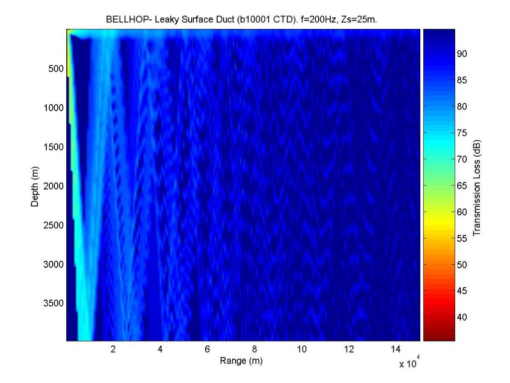
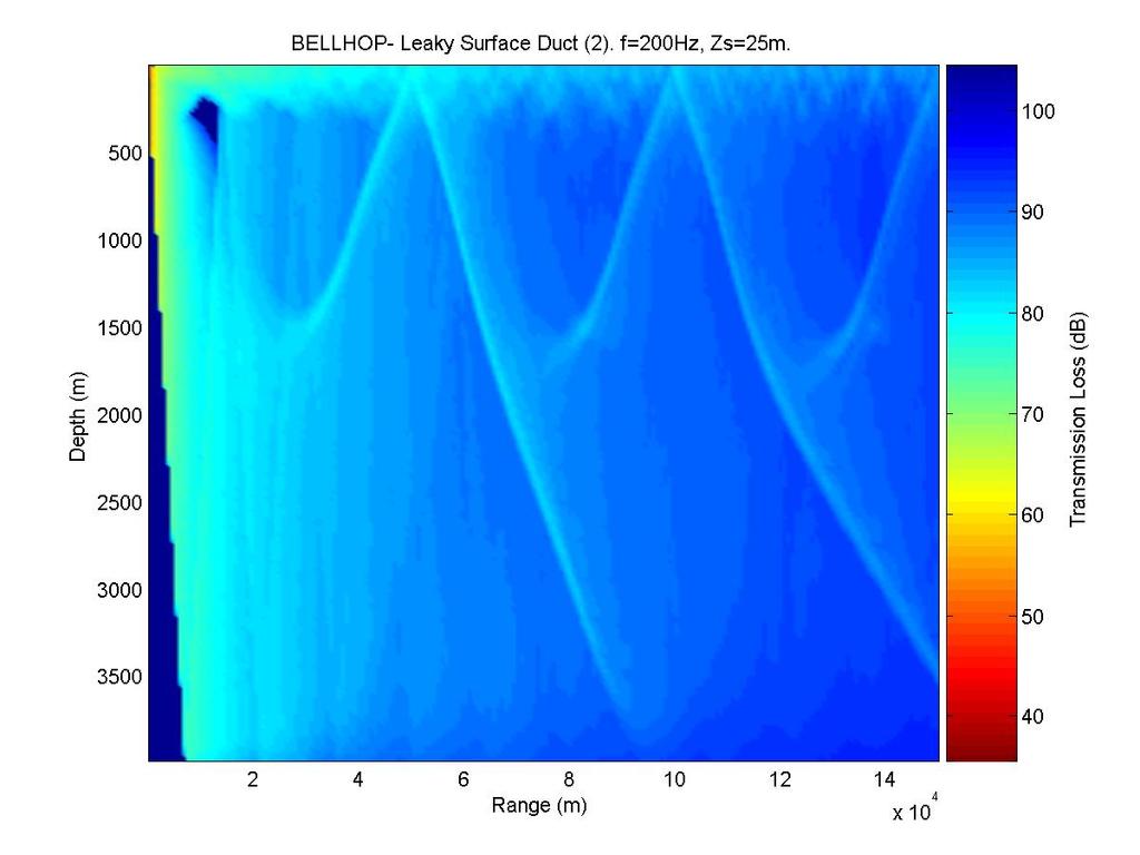
10 Underwater Acoustic Propagation Modeling Software For modeling the acoustic propagation over underwater channels we will use a software suit called the Acoustic Toolbox [1], written by Mike Porter. The original software was written in Fortran, which is not a commonly used programming language anymore. Alec Duncan provided a Matlab front-end [2] for the Acoustic Toolbox. In this section, we will provide an introduction to the Acoustic Toolbox and the user friendly Matlab front-end. The Acoustic Toolbox provides estimates for acoustic propagation of signals through the underwater channel by numerically solving propagation equations. The toolbox implements the following underwater acoustic propagation models: Kraken normal mode model [3], [4]: a normal mode code for range-varying environments in either Cartesian (line sources) or cylindrical (point sources) coordinates KrakenC complex normal mode model [5]: a complex normal mode code for range-varying environments in either Cartesian (line sources) or cylindrical (point sources) coordinates Scooter fast-field model: a finite element code for computing acoustic fields in range-independent environments based on direct computation of the spectral integral with pressure and material properties approximated by piecewise-linear elements Bellhop ray and Gaussian beam tracing model [6]: a program which computes acoustic fields in oceanic environments via beam tracing, with the environment being an acoustic medium with a sound speed which can depend on range and depth In addition, the toolbox can calculate Bounce bottom reflection coefficients for layered media. Acoustics Toolbox Front-End Users Manual The first step for the calculation of transmission loss and ray trace, you will need to define your environment. In this course, we will only focus on the effect of the sound speed profile and bottom reflections on the acoustic propagation. We will use the default bottom definition provided by the program. We will estimate the sound speed profile using the depth, temperature, and salinity information (measured by a CTD device). You can find real CTD data on some web sites or make your own measurements. For our example channel, we used the data set provided on the Bermuda Atlantic Time-Series Study web site [7], which can also be accessed through an ftp site [8]. We used a data set recorded in November
11 11
12 12
13 13
14 14
15 References [1] Acoustic Toolbox, URL: [2] Matlab front-end for Acoustic Toolbax, URL: [3] M.B. Porter and E.L. Reiss, A numerical method for ocean-acoustic normal modes, J. Acoust. Soc. Am., Vol. 76, pp , July1984 [4] M.B. Porter and E.L. Reiss, A numerical method for bottom interacting ocean acoustic normal modes, J. Acoust. Soc. Am., Vol. 77, pp , May1985 [5] M.B. Porter, The KRAKEN normal mode program, Rep. SM-245, SACLANTSEN, La Spezia, Italy, 1991 [6] M.B. Porter and H.P. Bucker, Gaussian beam tracing for computing ocean acoustic fields, J. Acoust. Soc. Amer., Vol. 82, pp , [7] 15
THESE notes describe the Matlab code for the Waymark
 WAYMARK BASED UNDERWATER ACOUSTIC CHANNEL SIMULATION Waymark Based Underwater Acoustic Channel Model - MATLAB code description I. INTRODUCTION THESE notes describe the Matlab code for the Waymark based
ON WAVEFORM SELECTION IN A TIME VARYING SONAR ENVIRONMENT
 ON WAVEFORM SELECTION IN A TIME VARYING SONAR ENVIRONMENT Ashley I. Larsson 1* and Chris Gillard 1 (1) Maritime Operations Division, Defence Science and Technology Organisation, Edinburgh, Australia Abstract
MULTIPATH EFFECT ON DPCA MICRONAVIGATION OF A SYNTHETIC APERTURE SONAR
 MULTIPATH EFFECT ON DPCA MICRONAVIGATION OF A SYNTHETIC APERTURE SONAR L. WANG, G. DAVIES, A. BELLETTINI AND M. PINTO SACLANT Undersea Research Centre, Viale San Bartolomeo 400, 19138 La Spezia, Italy
Channel. Muhammad Ali Jinnah University, Islamabad Campus, Pakistan. Multi-Path Fading. Dr. Noor M Khan EE, MAJU
 Instructor: Prof. Dr. Noor M. Khan Department of Electronic Engineering, Muhammad Ali Jinnah University, Islamabad Campus, Islamabad, PAKISTAN Ph: +9 (51) 111-878787, Ext. 19 (Office), 186 (Lab) Fax: +9
Multi-Path Fading Channel
 Instructor: Prof. Dr. Noor M. Khan Department of Electronic Engineering, Muhammad Ali Jinnah University, Islamabad Campus, Islamabad, PAKISTAN Ph: +9 (51) 111-878787, Ext. 19 (Office), 186 (Lab) Fax: +9
Exploiting nonlinear propagation in echo sounders and sonar
 Exploiting nonlinear propagation in echo sounders and sonar Fabrice Prieur 1, Sven Peter Näsholm 1, Andreas Austeng 1, Sverre Holm 1 1 Department of Informatics, University of Oslo, P.O. Box 1080, NO-0316
Characterization of a Very Shallow Water Acoustic Communication Channel MTS/IEEE OCEANS 09 Biloxi, MS
 Characterization of a Very Shallow Water Acoustic Communication Channel MTS/IEEE OCEANS 09 Biloxi, MS Brian Borowski Stevens Institute of Technology Departments of Computer Science and Electrical and Computer
Rec. ITU-R P RECOMMENDATION ITU-R P PROPAGATION BY DIFFRACTION. (Question ITU-R 202/3)
") Rec. ITU-R P.- 1 RECOMMENDATION ITU-R P.- PROPAGATION BY DIFFRACTION (Question ITU-R 0/) Rec. ITU-R P.- (1-1-1-1-1-1-1) The ITU Radiocommunication Assembly, considering a) that there is a need to provide
Rec. ITU-R P.- 1 RECOMMENDATION ITU-R P.- PROPAGATION BY DIFFRACTION (Question ITU-R 0/) Rec. ITU-R P.- (1-1-1-1-1-1-1) The ITU Radiocommunication Assembly, considering a) that there is a need to provide
Ocean Ambient Noise Studies for Shallow and Deep Water Environments
 DISTRIBUTION STATEMENT A. Approved for public release; distribution is unlimited. Ocean Ambient Noise Studies for Shallow and Deep Water Environments Martin Siderius Portland State University Electrical
Tackling the Sonar Equation
 Tackling the Sonar Equation V o 2αr TS G tvg G rec SL G 1 40log(r) 2D(φ,θ) LO: Apply characteristics of sound in water to calculate sound levels. John K. Horne Sonar Equation: Single Target V o = SL +
Passive Measurement of Vertical Transfer Function in Ocean Waveguide using Ambient Noise
 Proceedings of Acoustics - Fremantle -3 November, Fremantle, Australia Passive Measurement of Vertical Transfer Function in Ocean Waveguide using Ambient Noise Xinyi Guo, Fan Li, Li Ma, Geng Chen Key Laboratory
Numerical Modeling of a Time Reversal Experiment in Shallow Singapore Waters
 Numerical Modeling of a Time Reversal Experiment in Shallow Singapore Waters H.C. Song, W.S. Hodgkiss, and J.D. Skinner Marine Physical Laboratory, Scripps Institution of Oceanography La Jolla, CA 92037-0238,
Shallow water limits to hydro-acoustic communication baud rate and bit energy efficiency
 Shallow water limits to hydro-acoustic communication baud rate and bit energy efficiency Nicholas Andronis L3 Oceania Fremantle, Curtin University, ABSTRACT Shallow water hydro-acoustic communication channels
Acoustic Blind Deconvolution in Uncertain Shallow Ocean Environments
 DISTRIBUTION STATEMENT A: Approved for public release; distribution is unlimited. Acoustic Blind Deconvolution in Uncertain Shallow Ocean Environments David R. Dowling Department of Mechanical Engineering
Modeling Acoustic Signal Fluctuations Induced by Sea Surface Roughness
 Modeling Acoustic Signal Fluctuations Induced by Sea Surface Roughness Robert M. Heitsenrether, Mohsen Badiey Ocean Acoustics Laboratory, College of Marine Studies, University of Delaware, Newark, DE 19716
HIGH RESOLUTION MULTI-BEAM SIDE LOOKING SONAR ANDRZEJ ELMINOWICZ, LEONARD ZAJĄCZKOWSKI
 HIGH RESOLUTION MULTI-BEAM SIDE LOOKING SONAR ANDRZEJ ELMINOWICZ, LEONARD ZAJĄCZKOWSKI R&D Marine Technology Centre Dickmana 62, 81-109 Gdynia, POLAND email: andrzeje@ctm.gdynia.pl The conventional side
Appendix A Decibels. Definition of db
 Appendix A Decibels Communication systems often consist of many different blocks, connected together in a chain so that a signal must travel through one after another. Fig. A-1 shows the block diagram
Understanding How Frequency, Beam Patterns of Transducers, and Reflection Characteristics of Targets Affect the Performance of Ultrasonic Sensors
 Characteristics of Targets Affect the Performance of Ultrasonic Sensors By Donald P. Massa, President and CTO of Massa Products Corporation Overview of How an Ultrasonic Sensor Functions Ultrasonic sensors
Broadband Temporal Coherence Results From the June 2003 Panama City Coherence Experiments
 Broadband Temporal Coherence Results From the June 2003 Panama City Coherence Experiments H. Chandler*, E. Kennedy*, R. Meredith*, R. Goodman**, S. Stanic* *Code 7184, Naval Research Laboratory Stennis
Session2 Antennas and Propagation
 Wireless Communication Presented by Dr. Mahmoud Daneshvar Session2 Antennas and Propagation 1. Introduction Types of Anttenas Free space Propagation 2. Propagation modes 3. Transmission Problems 4. Fading
Exploitation of frequency information in Continuous Active Sonar
 PROCEEDINGS of the 22 nd International Congress on Acoustics Underwater Acoustics : ICA2016-446 Exploitation of frequency information in Continuous Active Sonar Lisa Zurk (a), Daniel Rouseff (b), Scott
The G4EGQ RAE Course Lesson 13 Pt1 Transmitter Power Measurements
 Transmitter Power Output Measurements. Introduction The Radio Amateur is limited to the transmitter power output as laid down in the BR68 schedule. Column 4 it gives the Maximum power level (in db relative
Contents. Telecom Service Chae Y. Lee. Data Signal Transmission Transmission Impairments Channel Capacity
 Data Transmission Contents Data Signal Transmission Transmission Impairments Channel Capacity 2 Data/Signal/Transmission Data: entities that convey meaning or information Signal: electric or electromagnetic
KULLIYYAH OF ENGINEERING
 KULLIYYAH OF ENGINEERING DEPARTMENT OF ELECTRICAL & COMPUTER ENGINEERING ANTENNA AND WAVE PROPAGATION LABORATORY (ECE 4103) EXPERIMENT NO 3 RADIATION PATTERN AND GAIN CHARACTERISTICS OF THE DISH (PARABOLIC)
ECE 476/ECE 501C/CS Wireless Communication Systems Winter Lecture 6: Fading
 ECE 476/ECE 501C/CS 513 - Wireless Communication Systems Winter 2004 Lecture 6: Fading Last lecture: Large scale propagation properties of wireless systems - slowly varying properties that depend primarily
Muhammad Ali Jinnah University, Islamabad Campus, Pakistan. Fading Channel. Base Station
 Fading Lecturer: Assoc. Prof. Dr. Noor M Khan Department of Electronic Engineering, Muhammad Ali Jinnah University, Islamabad Campus, Islamabad, PAKISTAN Ph: +9 (51) 111-878787, Ext. 19 (Office), 186 (ARWiC
ECE 476/ECE 501C/CS Wireless Communication Systems Winter Lecture 6: Fading
 ECE 476/ECE 501C/CS 513 - Wireless Communication Systems Winter 2005 Lecture 6: Fading Last lecture: Large scale propagation properties of wireless systems - slowly varying properties that depend primarily
Lecture 2 Physical Layer - Data Transmission
 DATA AND COMPUTER COMMUNICATIONS Lecture 2 Physical Layer - Data Transmission Mei Yang Based on Lecture slides by William Stallings 1 DATA TRANSMISSION The successful transmission of data depends on two
Resonance Tube. 1 Purpose. 2 Theory. 2.1 Air As A Spring. 2.2 Traveling Sound Waves in Air
 Resonance Tube Equipment Capstone, complete resonance tube (tube, piston assembly, speaker stand, piston stand, mike with adapters, channel), voltage sensor, 1.5 m leads (2), (room) thermometer, flat rubber
HIGH-FREQUENCY ACOUSTIC PROPAGATION IN THE PRESENCE OF OCEANOGRAPHIC VARIABILITY
 HIGH-FREQUENCY ACOUSTIC PROPAGATION IN THE PRESENCE OF OCEANOGRAPHIC VARIABILITY M. BADIEY, K. WONG, AND L. LENAIN College of Marine Studies, University of Delaware Newark DE 19716, USA E-mail: Badiey@udel.edu
Backscatter Estimation Using Broadband Acoustic Doppler Current Profilers
 Backscatter Estimation Using Broadband Acoustic Doppler Current Profilers Kent L. Deines, Member, IEEE Abstract Growing interest has developed in acoustic studies about the abundance and distributional
ECE 440L. Experiment 1: Signals and Noise (1 week)
") ECE 440L Experiment 1: Signals and Noise (1 week) I. OBJECTIVES Upon completion of this experiment, you should be able to: 1. Use the signal generators and filters in the lab to generate and filter noise
ECE 440L Experiment 1: Signals and Noise (1 week) I. OBJECTIVES Upon completion of this experiment, you should be able to: 1. Use the signal generators and filters in the lab to generate and filter noise
The Radio Channel. COS 463: Wireless Networks Lecture 14 Kyle Jamieson. [Parts adapted from I. Darwazeh, A. Goldsmith, T. Rappaport, P.
 The Radio Channel COS 463: Wireless Networks Lecture 14 Kyle Jamieson [Parts adapted from I. Darwazeh, A. Goldsmith, T. Rappaport, P. Steenkiste] Motivation The radio channel is what limits most radio
Data Communication. Chapter 3 Data Transmission
 Data Communication Chapter 3 Data Transmission ١ Terminology (1) Transmitter Receiver Medium Guided medium e.g. twisted pair, coaxial cable, optical fiber Unguided medium e.g. air, water, vacuum ٢ Terminology
ECE 476/ECE 501C/CS Wireless Communication Systems Winter Lecture 6: Fading
 ECE 476/ECE 501C/CS 513 - Wireless Communication Systems Winter 2003 Lecture 6: Fading Last lecture: Large scale propagation properties of wireless systems - slowly varying properties that depend primarily
The spatial structure of an acoustic wave propagating through a layer with high sound speed gradient
 The spatial structure of an acoustic wave propagating through a layer with high sound speed gradient Alex ZINOVIEV 1 ; David W. BARTEL 2 1,2 Defence Science and Technology Organisation, Australia ABSTRACT
Groundwave Propagation, Part One
 Groundwave Propagation, Part One 1 Planar Earth groundwave 2 Planar Earth groundwave example 3 Planar Earth elevated antenna effects Levis, Johnson, Teixeira (ESL/OSU) Radiowave Propagation August 17,
Data and Computer Communications Chapter 3 Data Transmission
 Data and Computer Communications Chapter 3 Data Transmission Eighth Edition by William Stallings Transmission Terminology data transmission occurs between a transmitter & receiver via some medium guided
Department of Electrical Engineering and Computer Science
 MASSACHUSETTS INSTITUTE of TECHNOLOGY Department of Electrical Engineering and Computer Science 6.161/6637 Practice Quiz 2 Issued X:XXpm 4/XX/2004 Spring Term, 2004 Due X:XX+1:30pm 4/XX/2004 Please utilize
The db Concept. Chapter six
 Chapter six The db Concept CHAPTER OUTLINE dbdpower Ratio... 40 dbdamplitude Ratio... 40 From db to Power or Amplitude Ratio... 41 Conversion Table... 41 Reference Values... 41 Other Relative Units...43
Doppler Effect in the Underwater Acoustic Ultra Low Frequency Band
 Doppler Effect in the Underwater Acoustic Ultra Low Frequency Band Abdel-Mehsen Ahmad, Michel Barbeau, Joaquin Garcia-Alfaro 3, Jamil Kassem, Evangelos Kranakis, and Steven Porretta School of Engineering,
What s an Analog Signal?
 What s an Analog Signal? Derived from the word analogous (analogous to the original signal) Our most powerful electronic systems are digital systems, e.g. computers, however, analog signals are required
Rec. ITU-R P RECOMMENDATION ITU-R P *
 Rec. ITU-R P.682-1 1 RECOMMENDATION ITU-R P.682-1 * PROPAGATION DATA REQUIRED FOR THE DESIGN OF EARTH-SPACE AERONAUTICAL MOBILE TELECOMMUNICATION SYSTEMS (Question ITU-R 207/3) Rec. 682-1 (1990-1992) The
High Frequency Acoustic Channel Characterization for Propagation and Ambient Noise
 High Frequency Acoustic Channel Characterization for Propagation and Ambient Noise Martin Siderius Portland State University, ECE Department 1900 SW 4 th Ave., Portland, OR 97201 phone: (503) 725-3223
Resonance Tube. 1 Purpose. 2 Theory. 2.1 Air As A Spring. 2.2 Traveling Sound Waves in Air
 Resonance Tube Equipment Capstone, complete resonance tube (tube, piston assembly, speaker stand, piston stand, mike with adaptors, channel), voltage sensor, 1.5 m leads (2), (room) thermometer, flat rubber
Resonance Tube Lab 9
 HB 03-30-01 Resonance Tube Lab 9 1 Resonance Tube Lab 9 Equipment SWS, complete resonance tube (tube, piston assembly, speaker stand, piston stand, mike with adaptors, channel), voltage sensor, 1.5 m leads
DISTRIBUTION STATEMENT A. Approved for public release; distribution is unlimited.
 DISTRIBUTION STATEMENT A. Approved for public release; distribution is unlimited. Propagation of Low-Frequency, Transient Acoustic Signals through a Fluctuating Ocean: Development of a 3D Scattering Theory
Antennas and Propagation
 Mobile Networks Module D-1 Antennas and Propagation 1. Introduction 2. Propagation modes 3. Line-of-sight transmission 4. Fading Slides adapted from Stallings, Wireless Communications & Networks, Second
Chapter 3 Data Transmission
 Chapter 3 Data Transmission COSC 3213 Instructor: U.T. Nguyen 1 9/27/2007 3:21 PM Terminology (1) Transmitter Receiver Medium Guided medium e.g. twisted pair, optical fiber Unguided medium e.g. air, water,
Week 1. Signals & Systems for Speech & Hearing. Sound is a SIGNAL 3. You may find this course demanding! How to get through it:
 Signals & Systems for Speech & Hearing Week You may find this course demanding! How to get through it: Consult the Web site: www.phon.ucl.ac.uk/courses/spsci/sigsys (also accessible through Moodle) Essential
Proceedings of Meetings on Acoustics
 Proceedings of Meetings on Acoustics Volume 19, 2013 http://acousticalsociety.org/ ICA 2013 Montreal Montreal, Canada 2-7 June 2013 Signal Processing in Acoustics Session 4aSP: Sensor Array Beamforming
Modern radio techniques
 Modern radio techniques for probing the ionosphere Receiver, radar, advanced ionospheric sounder, and related techniques Cesidio Bianchi INGV - Roma Italy Ionospheric properties related to radio waves
Chapter 17 Waves in Two and Three Dimensions
 Chapter 17 Waves in Two and Three Dimensions Slide 17-1 Chapter 17: Waves in Two and Three Dimensions Concepts Slide 17-2 Section 17.1: Wavefronts The figure shows cutaway views of a periodic surface wave
Good practice guide for C calculation
 Good practice guide for C calculation Albert Garcia-Benadí, Javier Cadena-Muñoz, David Sarrià- Gandul, Rafael Sitjar Cañellas, Joaquín del-río-fernández Universitat Politécnica de Catalunya, Grupo de investigación
ACOUSTIC REFLECTION AND TRANSMISSION EXPERIMENTS FROM 4.5 TO 50 KHZ AT THE SEDIMENT ACOUSTICS EXPERIMENT 2004 (SAX04)
") Proceedings of the International Conference Underwater Acoustic Measurements: Technologies &Results Heraklion, Crete, Greece, 28 th June 1 st July 2005 ACOUSTIC REFLECTION AND TRANSMISSION EXPERIMENTS
Proceedings of the International Conference Underwater Acoustic Measurements: Technologies &Results Heraklion, Crete, Greece, 28 th June 1 st July 2005 ACOUSTIC REFLECTION AND TRANSMISSION EXPERIMENTS
ECEN Network Analysis Section 3. Laboratory Manual
 ECEN 3714----Network Analysis Section 3 Laboratory Manual LAB 07: Active Low Pass Filter Oklahoma State University School of Electrical and Computer Engineering. Section 3 Laboratory manual - 1 - Spring
Digital Communications over Fading Channel s
 over Fading Channel s Instructor: Prof. Dr. Noor M Khan Department of Electronic Engineering, Muhammad Ali Jinnah University, Islamabad Campus, Islamabad, PAKISTAN Ph: +9 (51) 111-878787, Ext. 19 (Office),
Antennas and Propagation. Chapter 5
 Antennas and Propagation Chapter 5 Introduction An antenna is an electrical conductor or system of conductors Transmission - radiates electromagnetic energy into space Reception - collects electromagnetic
ESCI Cloud Physics and Precipitation Processes Lesson 10 - Weather Radar Dr. DeCaria
 ESCI 340 - Cloud Physics and Precipitation Processes Lesson 10 - Weather Radar Dr. DeCaria References: A Short Course in Cloud Physics, 3rd ed., Rogers and Yau, Ch. 11 Radar Principles The components of
International Journal of Research in Computer and Communication Technology, Vol 3, Issue 1, January- 2014
 A Study on channel modeling of underwater acoustic communication K. Saraswathi, Netravathi K A., Dr. S Ravishankar Asst Prof, Professor RV College of Engineering, Bangalore ksaraswathi@rvce.edu.in, netravathika@rvce.edu.in,
EC 554 Data Communications
 EC 554 Data Communications Mohamed Khedr http://webmail. webmail.aast.edu/~khedraast.edu/~khedr Syllabus Tentatively Week 1 Week 2 Week 3 Week 4 Week 5 Week 6 Week 7 Week 8 Week 9 Week 10 Week 11 Week
HIGH FREQUENCY INTENSITY FLUCTUATIONS
 Proceedings of the Seventh European Conference on Underwater Acoustics, ECUA 004 Delft, The Netherlands 5-8 July, 004 HIGH FREQUENCY INTENSITY FLUCTUATIONS S.D. Lutz, D.L. Bradley, and R.L. Culver Steven
Ultrasonic Level Detection Technology. ultra-wave
 Ultrasonic Level Detection Technology ultra-wave 1 Definitions Sound - The propagation of pressure waves through air or other media Medium - A material through which sound can travel Vacuum - The absence
THE SPEAKER. The decibel scale is related to the physical sound intensity measured in watts/cm 2 by the following equation:
 OBJECTIVES: THE SPEAKER 1) Know the definition of "decibel" as a measure of sound intensity or power level. ) Know the relationship between voltage and power level measured in decibels. 3) Illustrate how
Acoustic Blind Deconvolution and Frequency-Difference Beamforming in Shallow Ocean Environments
 DISTRIBUTION STATEMENT A. Approved for public release; distribution is unlimited. Acoustic Blind Deconvolution and Frequency-Difference Beamforming in Shallow Ocean Environments David R. Dowling Department
Channel Modeling ETI 085
 Channel Modeling ETI 085 Overview Lecture no: 9 What is Ultra-Wideband (UWB)? Why do we need UWB channel models? UWB Channel Modeling UWB channel modeling Standardized UWB channel models Fredrik Tufvesson
WIRELESS COMMUNICATIONS PRELIMINARIES
 WIRELESS COMMUNICATIONS Preliminaries Radio Environment Modulation Performance PRELIMINARIES db s and dbm s Frequency/Time Relationship Bandwidth, Symbol Rate, and Bit Rate 1 DECIBELS Relative signal strengths
Ultrasound Physics. History: Ultrasound 2/13/2019. Ultrasound
 Ultrasound Physics History: Ultrasound Ultrasound 1942: Dr. Karl Theodore Dussik transmission ultrasound investigation of the brain 1949-51: Holmes and Howry subject submerged in water tank to achieve
THE DECI REPORT. H. L. Dunegan. August, 2000 AN ALTERNATIVE TO PENCIL LEAD BREAKS FOR SIMULATION OF ACOUSTIC EMISSION SIGNAL SOURCES.
 THE DECI REPORT H. L. Dunegan August, 2000 AN ALTERNATIVE TO PENCIL LEAD BREAKS FOR SIMULATION OF ACOUSTIC EMISSION SIGNAL SOURCES. INTRODUCTION Over 25 years ago Nelson Hsu while working with Cliff Bailey
Computer Networks - Xarxes de Computadors
 Computer Networks - Xarxes de Computadors Outline Course Syllabus Unit 1: Introduction Unit 2. IP Networks Unit 3. Point to Point Protocols -TCP Unit 4. Local Area Networks, LANs 1 Outline Introduction
THESE notes describe the Matlab code for the Waymark
 WAYMARK BASED UNDERWATER ACOUSTIC CHANNEL SIMULATION Waymark Based Underwater Acoustic Channel Model - MATLAB code description I. INTRODUCTION THESE notes describe the Matlab code for the Waymark based
Computer modeling of acoustic modem in the Oman Sea with inhomogeneities
 Indian Journal of Geo Marine Sciences Vol.46 (08), August 2017, pp. 1651-1658 Computer modeling of acoustic modem in the Oman Sea with inhomogeneities * Mohammad Akbarinassab University of Mazandaran,
DECIBELS. This reading begins with the human senses of sight, touch and hearing.
 Reading 22 Ron Bertrand VK2DQ http://www.radioelectronicschool.com DECIBELS For some reason decibels are disliked by many, and misunderstood by many amateur radio operators, engineers, technicians and
Pulse Code Modulation
 Pulse Code Modulation EE 44 Spring Semester Lecture 9 Analog signal Pulse Amplitude Modulation Pulse Width Modulation Pulse Position Modulation Pulse Code Modulation (3-bit coding) 1 Advantages of Digital
CHARACTERISATION OF AN AIR-GUN AS A SOUND SOURCE FOR ACOUSTIC PROPAGATION STUDIES
 UDT Pacific 2 Conference Sydney, Australia. 7-9 Feb. 2 CHARACTERISATION OF AN AIR-GUN AS A SOUND SOURCE FOR ACOUSTIC PROPAGATION STUDIES Alec Duncan and Rob McCauley Centre for Marine Science and Technology,
Lab 1: Pulse Propagation and Dispersion
 ab 1: Pulse Propagation and Dispersion NAME NAME NAME Introduction: In this experiment you will observe reflection and transmission of incident pulses as they propagate down a coaxial transmission line
EE334 Gain and Decibels Worksheet
 EE334 Gain and Decibels Worksheet In electrical engineering one often finds situations where one is interested in either amplifying (making larger) or attenuating (making smaller) values such as voltage,
Lecture - 06 Large Scale Propagation Models Path Loss
 Fundamentals of MIMO Wireless Communication Prof. Suvra Sekhar Das Department of Electronics and Communication Engineering Indian Institute of Technology, Kharagpur Lecture - 06 Large Scale Propagation
Mobile Radio Propagation Channel Models
 Wireless Information Transmission System Lab. Mobile Radio Propagation Channel Models Institute of Communications Engineering National Sun Yat-sen University Table of Contents Introduction Propagation
Experimental Study of the Space-Time Properties of Acoustic Channels for Underwater Communications
 Experimental Study of the Space-Time Properties of Acoustic Channels for Underwater Communications Beatrice Tomasi, Giovanni Zappa, Kim McCoy, Paolo Casari, Michele Zorzi Department of Information Engineering,
Absorption: in an OF, the loss of Optical power, resulting from conversion of that power into heat.
 Absorption: in an OF, the loss of Optical power, resulting from conversion of that power into heat. Scattering: The changes in direction of light confined within an OF, occurring due to imperfection in
EENG473 Mobile Communications Module 3 : Week # (12) Mobile Radio Propagation: Small-Scale Path Loss
 Mobile Radio Propagation: Small-Scale Path Loss") EENG473 Mobile Communications Module 3 : Week # (12) Mobile Radio Propagation: Small-Scale Path Loss Introduction Small-scale fading is used to describe the rapid fluctuation of the amplitude of a radio
EENG473 Mobile Communications Module 3 : Week # (12) Mobile Radio Propagation: Small-Scale Path Loss Introduction Small-scale fading is used to describe the rapid fluctuation of the amplitude of a radio
Results from the Elba HF-2003 experiment
 Results from the Elba HF-2003 experiment Finn Jensen, Lucie Pautet, Michael Porter, Martin Siderius, Vincent McDonald, Mohsen Badiey, Dan Kilfoyle and Lee Freitag NATO Undersea Research Centre, La Spezia,
STATISTICAL MODELING OF A SHALLOW WATER ACOUSTIC COMMUNICATION CHANNEL
 STATISTICAL MODELING OF A SHALLOW WATER ACOUSTIC COMMUNICATION CHANNEL Parastoo Qarabaqi a, Milica Stojanovic b a qarabaqi@ece.neu.edu b millitsa@ece.neu.edu Parastoo Qarabaqi Northeastern University,
Antenna Performance. Antenna Performance... 3 Gain... 4 Radio Power and the FCC... 6 Link Margin Calculations... 7 The Banner Way... 8 Glossary...
 Antenna Performance Antenna Performance... 3 Gain... 4 Radio Power and the FCC... 6 Link Margin Calculations... 7 The Banner Way... 8 Glossary... 9 06/15/07 135765 Introduction In this new age of wireless
Ultrasound Beamforming and Image Formation. Jeremy J. Dahl
 Ultrasound Beamforming and Image Formation Jeremy J. Dahl Overview Ultrasound Concepts Beamforming Image Formation Absorption and TGC Advanced Beamforming Techniques Synthetic Receive Aperture Parallel
Modeling of underwater sonar barriers
 Acoustics 8 Paris Modeling of underwater sonar barriers A. Elminowicz and L. Zajaczkowski R&D Marine Technology Centre, Ul. Dickmana 62, 81-19 Gdynia, Poland andrzeje@ctm.gdynia.pl 3429 Acoustics 8 Paris
A Directional Dogbone Flextensional Sonar Transducer
 Excerpt from the Proceedings of the COMSOL Conference 21 Boston A Directional Dogbone Flextensional Sonar Transducer Stephen C. Butler Naval Undersea Warfare Center, Newport, RI 2841 Abstract: In order
Pre-Lab. Introduction
 Pre-Lab Read through this entire lab. Perform all of your calculations (calculated values) prior to making the required circuit measurements. You may need to measure circuit component values to obtain
Development of an Underwater Acoustic Communications Simulator
 Development of an Underwater Acoustic Communications Simulator C.A. Hamm M.L. Taillefer Maritime Scientific Way Ltd Prepared By: Maritime Scientific Way Ltd 2110 Blue Willow Crescent Orleans, ON K1W 1K3
UWB Channel Modeling
 Channel Modeling ETIN10 Lecture no: 9 UWB Channel Modeling Fredrik Tufvesson & Johan Kåredal, Department of Electrical and Information Technology fredrik.tufvesson@eit.lth.se 2011-02-21 Fredrik Tufvesson
8A. ANALYSIS OF COMPLEX SOUNDS. Amplitude, loudness, and decibels
 8A. ANALYSIS OF COMPLEX SOUNDS Amplitude, loudness, and decibels Last week we found that we could synthesize complex sounds with a particular frequency, f, by adding together sine waves from the harmonic
Ship source level. Aleksander Klauson, Janek Laanearu, Mirko Mustonen. Gothenburg, 01 June 2016
 Ship source level Aleksander Klauson, Janek Laanearu, Mirko Mustonen Gothenburg, 01 June 2016 Outline 1. Why ship noise? 2. How to measure ship noise. Testing methods. 3. Sources of ship noise. 4. Source
Lab S-3: Beamforming with Phasors. N r k. is the time shift applied to r k
 DSP First, 2e Signal Processing First Lab S-3: Beamforming with Phasors Pre-Lab: Read the Pre-Lab and do all the exercises in the Pre-Lab section prior to attending lab. Verification: The Exercise section
Sampling and Reconstruction
 Experiment 10 Sampling and Reconstruction In this experiment we shall learn how an analog signal can be sampled in the time domain and then how the same samples can be used to reconstruct the original
Week I AUDL Signals & Systems for Speech & Hearing. Sound is a SIGNAL. You may find this course demanding! How to get through it: What is sound?
 AUDL Signals & Systems for Speech & Hearing Week I You may find this course demanding! How to get through it: Consult the Web site: www.phon.ucl.ac.uk/courses/spsci/sigsys Essential to do the reading and
Antennas and Propagation
 Antennas and Propagation Chapter 5 Introduction An antenna is an electrical conductor or system of conductors Transmission - radiates electromagnetic energy into space Reception - collects electromagnetic
4: EXPERIMENTS WITH SOUND PULSES
 4: EXPERIMENTS WITH SOUND PULSES Sound waves propagate (travel) through air at a velocity of approximately 340 m/s (1115 ft/sec). As a sound wave travels away from a small source of sound such as a vibrating
Mobile Radio Propagation: Small-Scale Fading and Multi-path
 Mobile Radio Propagation: Small-Scale Fading and Multi-path 1 EE/TE 4365, UT Dallas 2 Small-scale Fading Small-scale fading, or simply fading describes the rapid fluctuation of the amplitude of a radio
Design and Implementation of Short Range Underwater Acoustic Communication Channel using UNET
 Design and Implementation of Short Range Underwater Acoustic Communication Channel using UNET Pramod Bharadwaj N Harish Muralidhara Dr. Sujatha B.R. Software Engineer Design Engineer Associate Professor