Table of Contents. Copyright 2012 Cellphone-Mate, Inc. All rights reserved.
|
|
|
- Susan Watts
- 5 years ago
- Views:
Transcription

1
2 Table of Contents Package Contents Features & Benefits How It Works About This Manual CHAPTER 2: Safety Safety Warnings CHAPTER 3: Planning Overview Exterior Antenna Interior Antennas Accessories Exterior Antenna Internal Antennas DIP Switches and Lights Powering on the Amplifier CHAPTER 6: Warranty Warranty Periods i
3 CM2500W Amplifier - Installation Manual Copyright & Trademark Information THIS MANUAL CONTAINS SAFETY, INSTALLATION, CONFIGURATION AND WARRANTY INFORMATION FOR YOUR CELLPHONE-MATE, INC (CMI) AMPLIFIER. CMI RECOMMENDS THAT YOU SAVE THIS MAN- UAL IN A READILY ACCESSIBLE LOCATION IN CASE ANY QUESTIONS ARISE ABOUT THIS PRODUCT. Copyright 2012 by Cellphone-Mate, Inc. All rights reserved. SureCall is a registered trademark and Cellphone-Mate is a trademark of Cellphone-Mate, Inc. All other trademarks or registered trademarks are the property of their respective owners. ii
. DC power supply (not shown).")
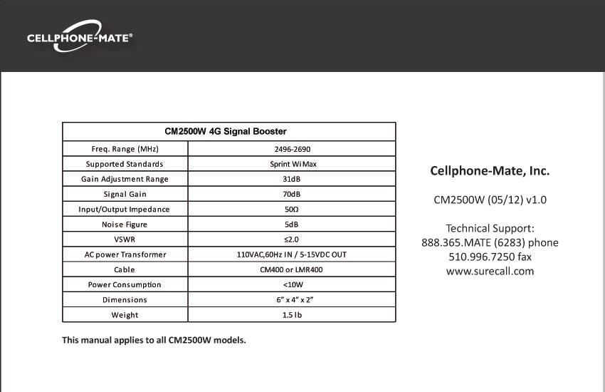
4 This chapter introduces the CM2500W Amplifier and this manual. Read this entire manual before proceeding with the installation. This manual is for all CM2500W models. CHAPTER 1: Introduction Package Contents Your amplifier box contains the following items: CM2500W amplifier. Mounting kit (not shown). DC power supply (not shown). Wall anchors (not shown). 1
5 CM2500W Amplifier - Installa Features & Benefits The CM2500W amplifier offers the following features and benefits: Powerful in-building amplifier with 31dB of adjustable gain level. Extends data signals in areas with poor coverage due to geographical loca and/or building design. Suitable for large areas up to about 30,000 square feet depending on outside signal strength and carrier frequency. Automa oscilla det and protecsystem powers down the amplifier to prevent harmful radio interference (if equipped). The CM2500W amplifier requires the following components for a complete installa 4G WiMAX compa antenna (such as the CM288W omni or CM230W Yagi by Cellphone-Mate, Inc.) Lightning protector (CMLP). Cable spli er if installing antennas (up to six in a typical installa tems Needed CM288W CM230W 2
6 Sufficient CM400 ultra low loss interior/exterior cable (for amplifiers above 55dB). Sufficient CM240 ultra low loss interior/exterior cable (for amplifiers 55dB and below). Grounded surge suppressor for DC power supply. CM288W CM230W How It Works CHAPTER 1: Intr The CM2500W amplifier boosts data signals from the nearest cellular tower to phones in a building and from those phones back to the tower to compensate for weak r caused by distance, topography, building structure, and/or other reasons. The amplifier receives the signal from an outside antenna, amplifies that signal, and then rebroadcasts it via the interior antenna(s) where it is picked up by cellular phones, modems, and data cards. The interior antennas also pick up signals from data devices and pass them to the amplifier. The amplifier boosts these signals and passes them to the exterior antenna for rebroadcast back to the tower. 3
7 CM2500W Amplifier - Installa About This Manual This manual contains the following informa Intr This chapter introduces the CM2500W amplifier and this manual. Safety: This chapter contains important safety informa Planning: This chapter describes how to plan your installa for best results. Installa This chapter describes how to install the amplifica system. Warranty: This chapter contains warran ty informa for your amplifica system. Regulatory Informa This chapter contains important regulatory agency informa Lists of items or points to consider that need not be performed in order appear in bullet format: Item 1 Item 2 Procedures that must be followed in a specific order appear in numbered steps: 1. Perform this step first. 2. Perform this step second. This manual also contains important safety informa and ins in specially forma ed callouts with accompanying graphic symbols: WARNING: WARNINGS INDICATE THE POSSIBILITY OF PERSONAL INJURY. CAUTION: WARNINGS INDICATE THE POSSIBILITY OF EQUIPMENT DAMAGE RADIO INTERFERENCE, ETC. Note: Notes provide helpful inf 4
8 This chapter contains important safety information designed to prevent personal injury, equipment malfunction, and/or radio interference. You are responsible for ensuring a safe installation Safety Warnings You are responsible for knowing and following all applicable codes and regulations and for obtaining all required permits and inspections. Follow all safety precautions contained in this Installation Manual. CHAPTER 2: Safety The installation process may require working in high locations such as roofs and/or ladders. Follow applicable safety regulations and best practices to avoid falling. Take care not to drop objects off any high area. Cordon off ground areas directly below roof or ladder work when possible. WARNING: FAILURE TO EXERCISE CAU- TION WHEN WORKING IN HIGH AREAS COULD CAUSE A FALL AND PERSONAL INJURY. Always use appropriate personal protective equipment such as goggles, gloves, hard hat, etc. as needed and as required. 5
9 CM2500W Amplifier - Installation Manual Some components may be heavy and/or bulky. Always use proper lifting and carrying techniques when handling components, especially when working on a ladder, roof, or other area with a fall hazard. The exterior antenna must not be co-located or operating in conjunction with any other antenna. Always use a properly installed Cellphone- Mate lightning protector between the exterior antenna and the amplifier. CAUTION: FAILURE TO PROPERLY INSTALL A LIGHTNING PROTECTOR CAN RESULT IN DAMAGE TO THE AMPLIFIER, ANTENNAS, AND WIRING. Always power off the amplifier before working on the roof of the building or anywhere in close proximity to the external antenna. Allow at least 24 inches (60cm) of separation between interior antennas and humans or animals. Allow at least 24 inches (60cm) of separation between exterior antennas and all persons. Comply with all antenna separation requirements to prevent signal oscillation. CAUTION: SIGNAL OSCILLATION CAN CAUSE RADIO INTERFERENCE WITH CELLULAR TOWERS AND RESULT IN CIVIL AND/OR CRIMINAL PENALTIES. 6
10 This chapter describes how to plan your amplifier installation, including how to determine the best locations for the inside and outside antennas Overview The general amplifier installation process follows these steps: 1. Decide where to mount the exterior antenna. This will generally be on the wall or roof of the building in the location with the strongest signal. You will need to decide whether to use an omnidirectional antenna mounted vertically CHAPTER 3: Planning or a directional Yagi antenna pointed directly at the cellular tower (line of sight). You must also consider attaching a grounded lightning protector between the exterior antenna and the amplifier. 2. Decide where to mount the interior antenna(s), being sure to take separation requirements into account. In general, long narrow spaces will benefit most from directional flat-panel antennas while more square spaces will benefit more from omnidirectional dome antennas. 3. Decide where to mount the amplifier. This should be in a secure indoor location near a grounded power source. 7
11 CM2500W Amplifier - Installa 4. Decide where to route the cables between the exterior antenna and the amplifier and between the amplifier and interior antennas. 5. Install the antennas as described in their r ve Installa 6. Route the cables to the amplifier loca 7. Install the amplifier as described in this manual. 8. Power on the amplifier and perform the configura and tes as described in this manual Exterior Antenna You may use either an omnidir antenna such as the CM288W (flat area with no obstrucor a dir Yagi antenna such as the CM230W (to point directly at the tower). The omnidir antenna receives and transmits signals over a horizontal 360-degree circle while the Yagi antenna receives and transmits signals over a focused area and must be aimed directly (line of sight) toward the cellular tower that provides the best signal to the building. The exterior antenna and mast (if any) must be mounted in a loca that meets all of the following criteria: Best signal strength. 8
12 CHAPTER 3: Planning Not collocated with other antennas or used in c ntennas. Away from all power lines. 6 from lightning rod antennas. 24 from all persons. These distances are general guidelines only; refer to the applicable building and electrical codes in your area to determine local requirements Interior Antennas You may use any combina of omnidir (dome) and/or dir (flat panel) interior antennas needed to obtain op signal strength throughout the building or installa area. Dome antennas such as the CM222W provide 360-degree hemispherical coverage suitable for mostly square areas while flat panel antennas such as the CM248W provide a focused zone of coverage suitable for long narrow areas. The following example uses two dome antennas and one panel antenna to provide full coverage (exterior Yagi antenna also shown): 9

13 CM2500W Amplifier - Installation Manual Keep in mind that floor structures in multistory buildings can cause significant signal loss, which means that you may need to install interior antennas on more than one floor. Here is an example of a multistory installation: Note: You may or may not need antennas on every floor of a multistory building depending on factors such as building material, amplifier gain, etc Antenna Separation Proper antenna separation is essential in order to prevent signal oscillation (feedback) that can interfere with the cellular tower. Separation is measured in a straight line from the exterior antenna to the closest interior antenna. The closest allowable distance depends on a number of factors such as amplifier gain level, building material, etc. Recommended separation distances are: Amplifier gain Min. separation (ad) 40dB 5 45dB dB 15 55dB 25 65dB 50 70dB 65 10
14 CHAPTER 3: Planning Note: Vertical separation is more important than horizontal separation. If you are unable to obtain the required separation horizontally, try raising the exterior antenna. You may also try reducing the amplifier gain as described in Chapter 5 of this manual. The easiest way to calculate the straight-line separation between antennas is to break it down into three simple measurements and then use some basic geometry to find the distance, as follows: 1. Measure the distances ab, bc, and cd as shown in the diagram on the next page. - Distance from the nearest interior antenna (Point a) to the wall underneath the exterior antenna (Point b). This is distance ab. - Distance from Point b to directly underneath the exterior antenna. This is Point (c). This is distance bc. - Distance from Point c to the exterior antenna (Point d). This is distance cd. 2. Multiply ab times ab to obtain ab Multiply bc times bc to obtain bc Multiply cd times cd to obtain cd Add ab 2 +bc 2 to obtain ac Add ac 2 +cd 2 to obtain ad 2. 11
 key.")
15 CM2500W Amplifier - Installation Manual 7. The straight-line distance ad is the square root ( ) of the result obtained in Step 6. Example: Distance ab=40 feet; ab 2 = 40x40=1600. Distance bc=10 feet; bc 2 = 10x10=100. Distance cd=20 feet; cd 2 = 20x20=400. ac 2 = =1700 ad 2 = =2100 ad = Note: Most calculators have a square root ( ) key. Here, the straight-line distance ad is just under 46 feet, which is compatible with 50dB amplifier gain as indicated in the previous table. Separate interior antennas based on the calculations shown in Section 3.5. You may mix and match dome and directional antennas as needed to obtain proper coverage throughout the building or area where you need to boost the signal. If you are using a Yagi exterior antenna, you should normally aim it away from all interior antennas regardless of separation to prevent oscillation. CAUTION: SIGNAL OSCILLATION CAN CAUSE RADIO INTERFERENCE WITH CELLULAR TOWERS AND RESULT IN CIVIL AND/OR CRIMINAL PENALTIES. 12
16 CHAPTER 3: Planning Calcula rength You can calculate the number of antennas you will need using the following parameters (in db): Outside signal level (OSL): This is the signal strength at the exterior antenna loca and will always be a nega ve number that will usually fall between -50 and -100dBm. Calls will drop at levels of about -100dB and lower. Outside antenna gain (OAG): This the signal boost provided by the exterior antenna and is always a ve number with Cellphone- Mate antennas. OAG 2500MHz WiMAX CM288W omni +3 CM230W Yagi +10 Inside antenna gain (IAG): This is the signal boost provided by an interior antenna and is always a ve number with Cellphone- Mate antennas. IAG 2500MHz WiMAX CM222W omni dome +3 CM248W dir +7 panel Cable loss (CL): This is the signal loss caused by the cable and is always a nega ve number. CL 2500MHz WiMAX 20 CM400/CM / CM400/CM / CM400/CM / CM400/CM /
17 CM2500W Amplifier - Installation Manual Splitter loss (SL): This is the signal loss caused by a splitter (used if you are installing multiple antennas). 2-way 3-way 4-way SL 2500MHz WiMAX Amplifier gain (AG): Number of decibels of amplification provided by the amplifier (rated gain less any attenuation, as described in Chapter 5 of this manual). This is always a positive number. The signal strength S at an interior antenna equals OSL+OAG+IAG+CL+SL+AG. To calculate the approximate coverage distance of each antenna: 1. Calculate the signal strength S for the first interior antenna using the preceding formula. 2. Find the signal strength S for the antenna along the bottom of the graph on the following page. 3. Move straight up the signal strength line to the PCS and cellular curves. 4. Read the approximate coverage radius on the left Amplifier Location Select an indoor location for the amplifier that meets the following criteria: Wall or ceiling mounts are acceptable. Near a properly grounded 110VAC outlet. Not in a tightly enclosed or overly hot space. All power and warning lights easily visible. Least amount of cable to connect all antennas. 14
18 CHAPTER 3: Planning Accessories The final step in the planning process is to make sure you have all of the necessary accessories to complete the installation. You will need all of the items listed in Chapter 1 of this manual plus some or all of the following: Cable clips: Use these to secure the cables to interior and exterior walls/ceilings. Appropriately rated sealant/caulking: Use this to waterproof the opening where the cable from the exterior antenna enters the building, if needed. Hand and/or power tools: As needed to complete the installation. Personal Protective Equipment (PPE): Use all PPE required by local codes and/or best practices to help ensure personal safety during installation. Note: You may need to obtain a permit from your local building department to install the amplifier and antennas. Check your local building and/or electrical codes. You do not need any permits from the FCC or the cellular carrier. CAUTION: YOU ARE RESPONSIBLE FOR ENSURING THAT THE INSTALLATION MEETS ALL APPLICABLE CODES. 15
19 CM2500W Amplifier - Installation Manual If you need help planning your installation, please contact a qualified installer, the reseller from whom you purchased the amplifier, or Cellphone- Mate, Inc. 16
20 This chapter describes how to install the amplifier and antennas for best results Selecting the Locations Select the locations for the exterior antenna, interior antenna(s), amplifier, cables, and accessories as described in the previous chapter. CAUTION: FAILURE TO PROPERLY PLAN THE AMPLIFIER INSTALLATION CAN CAUSE SIGNAL OSCILLATION AND/OR OTHER EQUIPMENT MALFUNCTION. CHAPTER 4: Installation Soft Installation Perform a soft installation of all components to test signal coverage and oscillation before making the installation permanent. Avoid making holes or other permanent fixtures during this initial phase. Please refer to Chapter 5 of this manual for configuration and testing instructions. Proceed with the final installation once configuration and testing are complete Exterior Antenna Mount the exterior antenna in the location you selected during the planning process. Be sure to follow all of the instructions included with the antenna to ensure a safe installation. Remember: 17
21 CM2500W Amplifier - Installa An omnidir antenna (CM288W) must be mounted v cally. A Yagi antenna (such as the CM230W) must be mounted horizontally and be aimed at the desired cellular tower (line of sight). CAUTION: MOUNT THE EXTERIOR ANTENNA ON A FIXED STRUCTURE. WARNING: FAILURE TO EXERCISE CAU- TION WHEN WORKING IN HIGH AREAS COULD CAUSE A FALL AND PERSONAL INJURY. WARNING: DO NOT TOUCH ANY LIVE ELECTRICAL WIRES OR ALLOW THE ANTENNA OR CABLING TO TOUCH ANY LIVE ELECTRICAL WIRES. CAUTION: AVOID AIMING A YAGI ANTENNA TOWARD ANY INTERIOR ANTENNA. 1. Mount the antenna. 2. Connect a length of CM400 cable to the ant hten un ht. 3. Run the cable along the planned route. 4. Install a properly grounded CMLP lightning protector. 5. Seal any holes you make in the outside of the building with appropriate caulking or sealant Internal Antennas Mount the interior antenna(s) in the loca you selected during the planning process. Be sure 18
22 CHAPTER 4: Installation to follow the instructions included with the antenna(s) for a safe installation. Remember: Dome antennas (CM222W, etc.) should be mounted in the ceiling as close to the center of the desired coverage area as possible with the domed side pointing down. Flat panel antennas (CM248W) should be wall-mounted as close as possible to center of the wall at one end of long narrow space. CAUTION: VERIFY THAT ALL INTERIOR ANTENNAS MEET THE SEPARATION REQUIREMENTS DESCRIBED IN THE PREVIOUS CHAPTER AND THAT NO ANTENNA IS AIMED TOWARD THE EXTERIOR ANTENNA. 1. Mount the antenna. 2. Connect a length of CM400 or CM240 cable to the antenna and tighten until hand-tight. 3. If you are installing multiple antennas, run the cable to the splitter location and connect the cable to one of the outputs on the splitter. 4. Connect another length of CM400 or CM240 cable to the input side of the splitter (if used) and run this cable to the amplifier location. CAUTION: DO NOT CONNECT AN INTERIOR ANTENNA TO THE SPLITTER INPUT Mounting the Amplifier Mount the amplifier as follows: 1. Verify that the selected location meets all of the criteria described in the previous chapter. 19
23 CM2500W Amplifier - Installation Manual 2. Attach the included mounting kit to the amplifier using the screws provided. Tighten the screws by hand with a screwdriver until snug plus 1/4 to 1/2 turn. Do not over-tighten. 3. Mount the amplifier to the wall using appropriate screws and/or wall anchors. The top side of the amplifier with the lights and DIP switches should be facing up and be plainly visible when standing near the amplifier. 4. Connect the exterior antenna cable to the Outside Antenna port on the amplifier. 5. Connect the interior antenna cable to the Inside Antenna port on the amplifier. 6. Verify that all cable connections are snug and that the exterior and interior antennas are connected to the proper jacks. CAUTION: DO NOT POWER ON THE AMPLIFIER UNTIL INSTRUCTED TO DO SO. CAUTION: NEVER POWER ON THE AMPLIFIER WHEN ANY ANTENNAS ARE DISCONNECTED AS THIS COULD DAM- AGE THE AMPLIFIER. 20
: Allows you to turn the amplifier on and off.")
24 This chapter describes how to power on, configure, and test the amplifier DIP Switches and Lights CHAPTER 5: Configuration & Testing Power switch (4): Allows you to turn the amplifier on and off. The CM2500W amplifier has the following indicators and controls: Gain DIP switches (1): These DIP switches control the amplification gain. Warning light (2): This light illuminates when signal oscillation is occurring. Power light (3): This light should always be illuminated or blinking green while the amplifier is powered on. When the amplifier is plugged in and powered on: The green Power light (3) should illuminate. 21

25 CM2500W Amplifier - Installation Manual The red Warning light (2) should remain OFF. If the Warning light illuminates, power off the amplifier immediately. The bank of DIP switches on the side of the amplifier contains five switches. Moving a switch down (toward from the base of the amplifier) turns that switch OFF and increases amplifier gain for the selected channel. Moving a switch up (away from the base of the amplifier) turns that switch ON and decreases amplifier gain for the selected channel. From left to right, the DIP switches provide 1, 2, 4, 8, and 16 db of attenuation (reduced amplification). These switches are cumulative, meaning that the total amount of attenuation for a channel is equal to the combined db of all ON DIP switches. For example: Turning all switches OFF = 0dB attenuation (amplifier is at full gain). Turning ON Switch #1 = 1dB attenuation (amplifier maximum gain is reduced by 1dB). Turning ON Switches #1, 3, and 5 = dB attenuation = 21dB attenuation. For example, in a 70dB amplifier, this means that the selected channel would be reduced to 49dB (70db-21db). Turning ON all switches = dB attenuation = 31dB attenuation. For example, in a 70dB amplifier, that means that the selected channel would be reduced to 39dB (70dB-31dB). 22
26 CHAPTER 5: Configuration & Testing Initial Configuration By default, your amplifier ships with all DIP switches turned OFF to provide maximum gain in all channels. This should always be your starting point whenever installing or reinstalling the amplifier Powering on the Amplifier To power on the amplifier: 1. Make sure both antenna cables are snugly connected to the proper amplifier ports. 2. Plug a surge suppressor into a grounded 110VAC wall outlet. 3. Plug the AC end of the power adapter that came with the amplifier into the surge suppressor. 4. Plug the DC end of the power adapter into the Power port on the amplifier 5. Power on the amplifier using the Power switch. CAUTION: ONLY USE THE POWER SUP- PLY INCLUDED WITH THE AMPLIFIER. USE OF ANOTHER POWER SUPPLY COULD DAMAGE THE AMPLIFIER AND/ OR POWER SUPPLY. 6. Verify that the green Power light is illuminated. 7. If the red Warning light illuminates, immediately power off the amplifier by either unplugging the DC power supply from the surge suppressor or by turning off the switch on the surge suppressor. Increase the attenuation 23
27 CM2500W Amplifier - Installa (reduce gain). If you are at maximum a enuaand s receiving a warning, then you must verify that all antennas have been placed according to these ins and relocate antennas as needed to eliminate the oscillafor more informa CAUTION: DO NOT PROCEED BEYOND THIS POINT UNTIL THE AMPLIFIER IS POWERED ON AND NO RED WARNING LIGHTS ARE ILLUMINATED. 8. Once the amplifier is powered on and the red Warning light is not illuminated, you may proceed to adjust the amplifier Tes Once the amplifier is powered on and the Warning light is not illuminated, walk around the en re area to test the data signal. Refine the antenna loca and/or gain levels as needed, and then complete the permanent installa system is working as desired Adjus Keep the following points in mind when adjus the amplifier: Full gain is not always your best op Your goal is to obtain a usable cellular signal in as many areas of the building as possible. A successful installa means that you can make calls without dropping and/or have a reliable data c 24
28 CHAPTER 5: Configuration & Testing Do not expect to see 5 bars of reception everywhere in the building as this is practically impossible. Also, signal strength in db can vary significantly without necessarily affecting the number of bars displayed because different phone and data card manufacturers handle bars sightly differently. A good rule of thumb is that increasing gain by 6dB doubles the coverage distance of the interior antennas. Start at the lowest gain setting and increase gain gradually as needed. If the red Warning light comes on, oscillation is either happening or is about to happen and protection circuits are activating (if equipped). If oscillation is or becomes severe, the amplifier will power down and will then wake every 30 seconds for the next 15 minutes to see if the problem has been resolved. If the problem has not been resolved after 15 minutes, the amplifier will shut off and will need to be unplugged and plugged back in again to reset. If you can t get the system to work properly, you may need to install an additional interior antenna and/or a different type of interior antenna and/or relocate interior antennas. 25
29 CM2500W Amplifier - Installation Manual Automatic Shutdown If equipped, the CM2500W amplifier includes an automatic shutdown feature that works in the following sequence: 1. When oscillation is detected in the uplink and/ or downlink, the Warning light will begin flashing red and the Power light will turn red. 2. If the problem is not resolved, the amplifier will shut down after 30 seconds. 3. The amplifier will wake back up. When this occurs, the Power light will be green. If oscillation resumes, the lights will flash as previously described. These 30-second cycles will continue for 15 minutes or until the problem is resolved. 4. If the problem is not resolved within 15 minutes, the amplifier will shut down (all lights off except the Power light, which is red) and must be reset by unplugging it from the power supply and plugging it back in. To resolve oscillation, increase the antenna separation (Section 3.4) and/or the attenuation (Section 5.1). 26
30 This chapter contains the warranty information for your CELLPHONE- MATE product and also contains information on how to contact the company Warranty Periods Your warranty includes the following periods: Two-Year Product Warranty: CELLPHONE- MATE products are covered under a two-year product warranty from the date of purchase. This protects the customer from any defects or problems the product may have that are CHAPTER 6: Warranty solely the fault of CELLPHONE-MATE Inc. Incorrect installation or misuse will void this warranty. Upon the return of a defective product, CELLPHONE-MATE will issue the customer a working replacement. All returned packages should contain all products distributed. Five-Year Extended Product Warranty: A five year warranty is available for purchase on any products sold by CELLPHONE-MATE Inc. A fiveyear warranty must be obtained at the time of purchase. This warranty adds an additional three years to the two year warranty we provide. All regulations still apply. 27
31 CM2500W Amplifier - Installation Manual Warranty Information 1. CELLPHONE-MATE, Inc. warrants to the Buyer that each of its products will be free from defects in material and workmanship and will perform in full accordance with applicable specifications when shipped. The limit of liability under this warranty is, at CELLPHONE- MATE, Inc. s option, to repair or replace any product or part thereof which shall, within TWO YEARS of purchase as determined by examination by CELLPHONE-MATE, Inc., prove defective in material and/or workmanship. Warranty returns must first be authorized in writing by CELLPHONE-MATE, Inc. Disassembly of any CELLPHONE-MATE, Inc. product by anyone other than an authorized representative of CELLPHONE-MATE, Inc. voids this warranty in its entirety. CELLPHONE-MATE, Inc. reserves the right to make changes in any of its products without incurring any obligation to make the same changes on previously delivered products. 2. As a condition of the warranties provided for herein, the Buyer will prepay the shipping charges for all products returned to CELL- PHONE-MATE, Inc. for repair and CELLPHONE- MATE, Inc. will pay the return shipping with the exception of product returned from outside the United States, in which case the Buyer will pay all shipping charges. 3. The Buyer will pay the cost of inspecting and testing any goods returned under the warranty or otherwise which are found to meet the applicable specifications or which are not defective or not covered by this warranty. 4. Products sold by CELLPHONE-MATE, Inc. shall not be considered defective or non-conform- 28
32 CHAPTER 6: Warranty ing to the Buyer s order if they satisfactorily fulfill the performance requirements that were published in the product specification literature, or in accordance with samples provided by CELLPHONE-MATE, Inc. This warranty shall not apply to any products or parts thereof which have been subject to accident, negligence, alteration, abuse, or misuse. CELL- PHONE-MATE, Inc. makes no warranty whatsoever in respect to accessories or parts not supplied by it. 5. Limitations of Warranty, Damages and Liability: EXCEPT AS EXPRESSLY SET FORTH HEREIN, THERE ARE NO WARRANTIES, CONDITIONS, GUARANTEES OR REPRESENTATIONS AS TO MERCHANTABILITY, FITNESS FOR A PARTICU- LAR PURPOSE OR OTHER WARRANTIES, CON- DITIONS, GUARANTEES OR REPRESENTATIONS, WHETHER EXPRESSED OR IMPLIED, IN LAW OR IN FACT, ORAL OR IN WRITING. CELLPHONE-MATE, INC. S AGGRE- GATE LIABILITY IN DAMAGES OR OTHERWISE SHALL NOT EXCEED THE PAYMENT, IF ANY, RECEIVED BY CELLPHONE-MATE, INC. FOR THE UNIT OF PRODUCT OR SERVICE FURNISHED OR TO BE FURNISHED, AS THE CASE MAY BE, WHICH IS THE SUBJECT OF CLAIM OR DIS- PUTE. IN NO EVENT SHALL CELLPHONE-MATE, INC. BE LIABLE FOR INCIDENTAL, CONSEQUEN- TIAL, OR SPECIAL DAMAGES, HOWSOEVER CAUSED. 6. All matters regarding this warranty shall be interpreted in accordance with the laws of the State of California and any controversy that cannot be settled directly shall be settled by arbitration in California in accordance with the rules then prevailing of the American Arbitration Association, and judgment upon the 29
33 CM2500W Amplifier - Installation Manual award rendered may be entered in any court having jurisdiction thereof. 7. If one or more provisions provided herein are held to be invalid or unenforceable under applicable law, then such provision shall be ineffective and excluded to the extent of such invalidity or unenforceability without affecting in any way the remaining provisions herein. 8. CELLPHONE-MATE reserves the right to bill for labor spent on equipment where there is no defective found 9. All items that are out of warranty are subject to a repair fee and additional freight charges. 10. Defective items in warranty will be repaired at no additional charge and will be returned with freight paid by CELLPHONE-MATE Contact Information You may consult a Cellphone-Mate, Inc. customer service agent directly by contacting us as follows: View the list of Frequently Asked Questions (FAQ) online at tech_faq.html. Our online support center is at If needed, you can create an online support ticket. This is the fastest and best way to get support for your product. Write to the address at the web site or call the phone number on the back cover of this manual. 30
34 This chapter contains the regulatory information for the FCC (USA) FCC Information FCC ID: RSNCM2500W Warning: Changes or modifications to this device not expressly approved by Cellphone-Mate, Inc. could void the user s authority to operate the equipment. Note: This equipment has been tested and found to comply with the limits pursuant to Part 27 of the FCC Rules. These limits are designed to provide reasonable protection against harmful interference in a residential installation. This CHAPTER 7: Regulatory Information equipment generates, uses, and can radiate radio frequency energy and, if not installed and used in accordance with the instructions, may cause harmful interference to radio communications. However, there is no guarantee that interference will not occur in a particular installation. If the equipment does cause harmful interference to radio or television reception, which can be determined by turning the equipment off and on, the user is encouraged to try to correct the interference by one or more of the following measures: Reorient or relocate the receiving antenna. Increase the separation between the equipment and receiver. 31
35 CM2500W Amplifier - Installation Manual Connect the equipment to an outlet on a circuit different from that to which the receiver is connected. Consult the dealer or an experienced radio/tv technician for help. This equipment complies with FCC radiation exposure limits set forth for an uncontrolled environment. This transmitter must not be co-located or operating in conjunction with any other antenna or transmitter. In accordance with FCC requirements of human exposure to radio frequency fields, the radiating element (antenna) shall be installed such that a minimum separation distance of 60cm (24in) is maintained from all persons. 32
36
Table of Contents Copyright 2012 Cellphone-Mate, Inc. All rights reserved.
 Table of Contents - - - - - - - - - - - - - - - 1 1.1 - Package Contents - - - - - - - - - - - - - - - - 1 1.2 - Features & Benefits - - - - - - - - - - - - - - - 2 - - - - - - - - - - - 2 1.4 - How It
DualForce Industrial. User Guide. Dual-Band Cellular Booster for Commercial Offices, Institutions and Housing Complexes. WARNING
 DualForce Industrial Dual-Band Cellular Booster for Commercial Offices, Institutions and Housing Complexes. User Guide WARNING This is NOT a CONSUMER device. It is designated for installation by FCC LICENSEES
SureCall TM CM800 65dB
 SureCall TM CM800 65dB Cellular Band Building Repeater User Manual Model: CM800 FCC ID: RSNCM2000 CONTENTS OF THE PACKAGE fdgbsddg 1. CM800 Amplifier with connectors: N female type 2. Mounting Kit 3. 110V
SureCall TM CM dB Dual Band Universal Inbuilding Repeater
 SureCall TM CM2020 65dB Dual Band Universal Inbuilding Repeater User Manual Model: CM2020 65dB FCC ID: RSNDUAL-65UNDER CANADA IC:7784A-D65UNDER wpsantennas.com 1-877-594-5766 CONTENTS OF THE PACKAGE fdgbsddg
Force5 Industrial. User Guide. 5-Band Cellular Booster for Commercial Offices, Institutions and Housing Complexes. WARNING
 Force5 Industrial 5-Band Cellular Booster for Commercial Offices, Institutions and Housing Complexes. User Guide WARNING This is NOT a CONSUMER device. It is designated for installation by FCC LICENSEES
Fusion5S. 3G - 4G Home Five-Band Signal Booster Kit. User Guide
 Fusion5S 3G - 4G Home Five-Band Signal Booster Kit User Guide Table of Contents Thank you for purchasing SureCall s Fusion5s cellular signal booster kit. Fusion5s was specifically designed to eliminate
User's Manual F10G-5S-LCD 1 / 20 BOOST CELL PHONE SIGNAL BOOSTERS MADE BY HUAPTEC
 User's Manual F10G-5S-LCD 1 / 20 BOOST CELL PHONE SIGNAL BOOSTERS MADE BY HUAPTEC Table of contents WHAT IS INCLUDED... 3 1 HOW IT WORKS... 3 2 TOOL REQUIRED... 3 3 HOW TO INSTALL YOUR NEW CELLULAR BOOSTER...
Guide. Installation. Wilson Electronics, Inc. In-Building Wireless Amplifi er. Contents:
 Amplifier Installation Guide In-Building Wireless Amplifi er Contents: Guarantee and Warranty 1 Antenna Options and Accessories 2 Before Getting Started / How It Works 2 Installation Overview 3 Installation
FlexPro. 2G - 3G Home or Office Signal Booster Kit. User Guide
 FlexPro 2G - 3G Home or Office Signal Booster Kit User Guide Thank you for your purchase of SureCall s FlexPro cellular signal booster kit. FlexPro was specifically designed to eliminate frustrations over
Fusion5. 3G - 4G Home or Office Five-Band Signal Booster Kit. User Guide
 Fusion5 3G - 4G Home or Office Five-Band Signal Booster Kit User Guide Table of Contents Thank you for purchasing SureCall s Fusion5 cellular signal booster kit. Fusion5 was specifically designed to eliminate
Wilson. iden 800 MHz. Adjustable Gain In-Building Wireless Smart Technology Signal Booster. Appearance of device and accessories may vary.
 iden 800 MHz Adjustable Gain In-Building Wireless Smart Technology Contents: Options & Accessories....................... 1 Quick Install Overview............................... 2 Installation Diagram.................................
Force5 2.0 Industrial
 Force5 2.0 Industrial Cellular Signal Booster for voice and 4G data with Built- In Sentry Monitoring User Guide Table of Contents CONTENTS Chapter 1: Introduction...3 1.1 Package Contents...3 1.2 Features
Guide. Installation. Wilson Electronics, Inc. In-Building Wireless Amplifi er. Contents:
 Amplifier Installation Guide In-Building Wireless Amplifi er Contents: Guarantee and Warranty 1 Antenna Options and Accessories 2 Before Getting Started / How It Works 3 Installation Overview 4 Installing
Appearance of device and accessories may vary.
 Tri-Band 4G-V Adjustable Gain 700 (Band 13) / 800 / 1900 MHz In-Building Wireless Smart Technology Signal Booster (Band 13 is 700 MHz Verizon LTE) Tri-Band 4G-A Adjustable Gain 700 (Band 12/17) / 800 /
Dual-Band Wireless Adjustable Cellular Booster / Kit
 Dual-Band Wireless Adjustable Cellular Booster / Kit INTRODUCTION 2 PRINCIPLES OF OPERATION 2 SURECALL FLEX 2GO PACKAGES 3 FLEX 2GO BOOSTER HARDWARE 4 PACKAGE CONTENTS 5 SITE SELECTION 5 INSTALLATION INSTRUCTIONS
Aura 2G-3G Wireless Adjustable Cellular Booster Kit
 Aura 2G-3G Wireless Adjustable Cellular Booster Kit Introduction Theory of Operation 1 Packages Contents 2 Booster Hardware 2 Installation MN-CA-VAT V2.0 3-9 Quick Install Guide 3 Configuring Gain Settings
ORiNOCO AP-4000MR-LR and AP-4900MR-LR Access Points Safety and Regulatory Compliance Information
 IMPORTANT! Visit http://support.proxim.com for the latest safety and regulatory compliance information for this product. ORiNOCO AP-4000MR-LR and AP-4900MR-LR Access Points Safety and Regulatory Compliance
RFTX-1 Installation Manual
 RFTX-1 Installation Manual complete control Universal Remote Control RFTX-1 Installation Manual 2009-2014 Universal Remote Control, Inc. The information in this Owner s Manual is copyright protected. No
NEO CAR AUDIO. Neo AUXiN AUX INPUT INTERFACE. Instruction Manual
 NEO CAR AUDIO Neo AUXiN AUX INPUT INTERFACE Instruction Manual IMPORTANT NOTE Neo AUXiN Dip switch positions MUST be set BEFORE any other step is taken. Otherwise, the kit will not operate properly. See
Installation and Operation Manual MSI. Multi-Sensor Interface Hub. Interface Module for all Sensors Network and Wireless CAUTION
 Installation and Operation Manual MSI Multi-Sensor Interface Hub Interface Module for all Sensors Network and Wireless CAUTION This equipment complies with the limits for a Class B digital device, pursuant
Appearance of device and accessories may vary.
 Mobile 4G Smart Technology Signal Booster Contents: How it Works.... 1 Before Getting Started.... 2 Quick Installation Overview.... 2 Installing the Outside Antenna.... 2 Installing the Low-Profile Antenna....
PowerMax TM 4KSBR-50U
 Installation and Operation Manual PowerMax TM 4KSBR-50U 60dB Gain Dual Band Wireless Amplifier/Repeater System Read Instructions before installing! If you do not understand instructions, seek professional
Xpress Satellite Radio Receiver
 Xpress Satellite Radio Receiver XMH10 Home Cradle Installation Guide -1- Released 9-15-05. 1 of 12 CONTENTS Congratulations... 3 Cautions and Warnings... 4 Contents XMH10... 5 Installation/Wiring Precautions...
Stealth X2 Dual Band Boosters
 Stealth X2 Dual Band Boosters BUILDINGS HOMES COTTAGES Stealth X2 Dual Band Boosters Table of Contents Features...3 Specifications...3 Package contents...4 Optional Parts...4 Antenna and Booster Installation...5
Guide. Installation. Wilson Electronics, Inc. Direct Connection High Power iden Amplifi er 800 MHz Band. Contents:
 Amplifier Installation Guide Direct Connection High Power iden Amplifi er 800 MHz Band Contents: Guarantee and Warranty 1 Before Getting Started / How it Works 3 Installing a Wilson Outside Antenna - In-Vehicle
IRRIGATION 810-T PLUS TRANSMITTER GUIDE
 IRRIGATION 810-T PLUS TRANSMITTER GUIDE Pg. 2 HOT SHOT OVERVIEW 3 BASIC WIRING INSTRUCTIONS 4 HOW TO CONTROL AND SHARE MULTIPLE WELLS 5 TRANSMITTER FUNCTION SWITCH SETTINGS 5 LED INDICATORS 5 OPERATING
Contents. Page English 1. French. Spanish. Reset of MIN/MAX records 915 MHz Reception Mounting Care and Maintenance Warranty Information
 Contents Language Page English 1 French Spanish WIRELESS 915 MHz TEMPERATURE STATION Instruction Manual TABLE OF CONTENTS Topic Page Inventory of Contents Features Setting Up Battery Installation Function
INSTALLATION AND OPERATING MANUAL
 INSTALLATION AND OPERATING MANUAL FOR RBDA-PCS-1/25W-90-A INDOOR REPEATER TABLE OF CONTENTS PARAGRAPH PAGE NO BDA OVERVIEW 3 BDA BLOCK DIAGRAM DESCRIPTION 3 FCC INFORMATION FOR USER 3 BDA BLOCK DIAGRAM
Operating Instructions
 3000 Operating Instructions Contents Introduction 1 Operating Instructions 2-4 Demonstrations 5-6 Storing/Handling/Cleaning 7 Safety Precautions 7-8 Specifications 8 FCC Compliance Statement 9-10 Limited
PTE-C70 Cell Phone Signal Booster User Manual
 PTE-C70 Cell Phone Signal Booster User Manual 1 / 8 SAFETY WARNINGS W ARNI NG: This equipm ent should be installed and operated w ith m inim um distance 2 0 cm betw een the radiator& your body. FCC Cautions:
Wireless Transceiver (TRV)
") Installation and Operation Manual Wireless Transceiver (TRV) For Platinum Controls with Communication WARNING This equipment complies with the limits for a Class B digital device, pursuant to Part 15 of
Installation and Operation Manual Wireless Transceiver (TRV) For Platinum Controls with Communication WARNING This equipment complies with the limits for a Class B digital device, pursuant to Part 15 of
FlexPro Canada. 2G - 3G Home or Office Signal Booster Kit. User Guide
 FlexPro Canada 2G - 3G Home or Office Signal Booster Kit User Guide Table of Contents Thank you for your purchase of SureCall s FlexPro Canada cellular signal booster kit. FlexPro Canada was specifically
Ambient Weather F007TP 8-Channel Wireless Probe Thermometer User Manual
 Ambient Weather F007TP 8-Channel Wireless Probe Thermometer User Manual Table of Contents 1 Introduction... 2 2 Getting Started... 2 2.1 Parts List... 2 2.2 Probe Thermometer Sensor Set Up... 2 3 Remote
In-VehicleMAXIMUMSIGNALUSER GUIDE. Wireless Dual Band Amplifier
 In-VehicleMAXIMUMSIGNALUSER GUIDE Wireless Dual Band Amplifier TM Contents Warnings...2 Package Contents...2 Quick Start Guide...4 Choosing a location for your device...4 Installing the Exterior Antenna...5
What bands and wireless providers are served with this booster? Frequency Bands: LTE-707(Band12, 17)/LTE-781(Band13)/Cellular850
/LTE-781(Band13)/Cellular850") What bands and wireless providers are served with this booster? Frequency Bands: LTE-707(Band12, 17)/LTE-781(Band13)/Cellular850 (Band5)/PCS-1900(Band2, 25)/AWS2100 (Band4). This equipment is a multiband
What bands and wireless providers are served with this booster? Frequency Bands: LTE-707(Band12, 17)/LTE-781(Band13)/Cellular850 (Band5)/PCS-1900(Band2, 25)/AWS2100 (Band4). This equipment is a multiband
Copyright Teletronics International, Inc. Patent Pending
 Copyright 2003 By Teletronics International, Inc. Patent Pending FCC NOTICES Electronic Emission Notice: This device complies with Part 15 of the FCC rules. Operation is subject to the following two conditions:
SIR-WRR1. User's Guide SIRIUS Echo Antenna. Signal Repeater System Accessory
 SIR-WRR1 User's Guide SIRIUS Echo Antenna Signal Repeater System Accessory Desktop SIRIUS Docking Echo Station Antenna FCC NOTICE: This device complies with part 15 of the FCC Rules and with RSS-210 of
Contact Tech Support at or at Safety and Warnings
 ! Safety and Warnings Turn AC power OFF at the mains before working on any electrical connections. All AC power wiring and coaxial cable wiring must conform to local or national codes. The AC line voltage
F10I-EGSM Single System
 F10I-EGSM Single System 1 Table of contents How it works... 3 Package contents... 4 Troubleshooting... 14 Specifications... 15 Product Warranty... 16 Safety Warnings... 17 2 How it works Huaptec F10I-EGSM
A-16D A-Net Distributor
 A-16D A-Net Distributor For use with the Personal Monitor Mixing System Information in this document is subject to change. All rights reserved. Copyright 2003 Aviom, Inc. Printed in USA Document Rev. 1.03
User s Guide FM Transmitter
 TM 12-634 User s Guide FM Transmitter Please read this user s guide before using your new FM Transmitter. 12-634_en.indd 1 Package contents FM Transmitter USB Cable User s Guide Quick Start IMPORTANT SAFETY
Contact Tech Support at or at Safety and Warnings
 ! Safety and Warnings Turn AC power OFF at the mains before working on any electrical connections. All AC power wiring and coaxial cable wiring must conform to local or national codes. The AC line voltage
Technical Support, End User License & Warranty Information
 Technical Support, End User License & Warranty Information How to get Technical Support Pazzles provides free Technical Support for your Inspiration Vūe for a period of 1 year from the date of purchase.
WS-7220U-IT 915 MHz Wireless Weather Station. Instruction Manual
 WS-7220U-IT 915 MHz Wireless Weather Station Instruction Manual 1 TABLE OF CONTENTS Introduction..3 Inventory of Contents 4 Quick Set Up 4 Detailed Set Up 4-5 Battery Installation....4-5 12 or 24 Hour
SolidRF SOHO Tri-Band Cell Phone Signal Booster for GSM, GPRS, CDMA 3G and Verizon 4G LTE. 700 MHz(Band 13) / 850 MHz / 1900 MHz ONLY
 / 850 MHz / 1900 MHz ONLY") SolidRF SOHO Tri-Band Cell Phone Signal Booster for GSM, GPRS, CDMA 3G and Verizon 4G LTE 700 MHz(Band 13) / 850 MHz / 1900 MHz ONLY If you have any questions or concerns when installing or operating your
SolidRF SOHO Tri-Band Cell Phone Signal Booster for GSM, GPRS, CDMA 3G and Verizon 4G LTE 700 MHz(Band 13) / 850 MHz / 1900 MHz ONLY If you have any questions or concerns when installing or operating your
Driveway Alarm INSTALLATION MANUAL
 WIRELESS ACCESS CONTROLS Driveway Alarm INSTALLATION MANUAL Mounting post Transmitter Receiver Transformer Sensor Kit Includes: Transmitter Module Sensor Receiver Transformer Mounting post (3 pieces) Installation
How to install your ecobee Switch+
 How to install your ecobee Switch+ Warning Installing this product involves handling high voltage wiring. Each step of the enclosed instructions must be followed carefully. To avoid fire, personal injury,
Cellular Signal Booster Multi-User Tri-Band
 weboost Drive AM100-Pro Cellular Signal Booster Multi-User Tri-Band ! THE Drive AM100-Pro SIGNAL BOOSTER MAY REMAIN ON, IN VEHICLES WHOSE 12V DC POWER SOURCES DO NOT AUTOMATICALLY SHUTDOWN WHEN THE VEHICLE
SP GHz Digital Wireless Speakers. User s Manual. Please read before using the equipment. Please visit for details.
 SP1390 2.4GHz Digital Wireless Speakers User s Manual Please read before using the equipment. Please visit www.promowide.com for details. INTRODUCTION This 2.4G digital wireless speakers system uses latest
A WILSON ELECTRONICS BRAND DRIVE 4G-X FLEET PROFESSIONAL VEHICLE CELLULAR SIGNAL BOOSTER KIT. User Manual. NEED HELP? support.weboost.com
 A WILSON ELECTRONICS BRAND DRIVE 4G-X FLEET PROFESSIONAL VEHICLE CELLULAR SIGNAL BOOSTER KIT User Manual NEED HELP? support.weboost.com 866.294.1660 Index Package Contents 1 STEP 1: Mount Outside Antenna
F10-GSM Single System
 F10-GSM Single System 1 Table of content How it works... 3 Package contents... 4 Install your hardware... 5 Troubleshooting... 14 Specifications... 15 Product Warranty... 16 Safety Warnings... 17 2 How
AIS 300 Installation Instructions
 Use these instructions to install the Garmin AIS 300 Automatic Identification System (AIS) Class B receiver device. Compare the contents of this package with the packing list on the box. If any pieces
CELLULAR DISTRIBUTION SYSTEM
 Overview OCC s patented Cellular Distribution System (CDS) is a wireless enhancement product designed to resolve low cellular signal strength issues for in-building applications. Designed as a complete
Field Hub Installation Guide. P/N Rev. C 05/15
 Field Hub Installation Guide P/N016-0171-380 Rev. C 05/15 E21714 Copyright 2015 Disclaimer While every effort has been made to ensure the accuracy of this document, Raven Industries assumes no responsibility
A WILSON ELECTRONICS BRAND DRIVE 4G-X OTR. Cellular Booster For Trucks. User Manual. NEED HELP? support.weboost.com
 A WILSON ELECTRONICS BRAND DRIVE 4G-X OTR Cellular Booster For Trucks User Manual NEED HELP? support.weboost.com 866.294.1660 Index Package Contents 1 STEP 1: Select Mounting Location 2 STEP 2: Assemble
Cellular Signal Booster
 Home 3G Cellular Signal Booster !! IT IS VERY MPORTANT TO POWER YOUR SIGNAL BOOSTER US NG A SURGE PROTECTED AC POWER STRIP WITH AT LEAST A 1000 JOULE RATING. FAILURE TO DO THIS WILL VOID YOUR WARRANTY
T-L 810-T TRANSMITTER GUIDE
 T-L 810-T TRANSMITTER GUIDE Pg. 2 HOW IT WORKS 2 TEST BEAC 3 MOUNTING 3 CODE SWITCH SETTINGS 3 BATTERY BACKUP 3 TRANSMITTER FUNCTI SWITCH SETTINGS 3 INDICATOR LEDS 4 T-L ELECTRIC PANEL 5 T-L PPC III ENGINE
TONE ALERT RECEIVER MODEL 2TR9A. P.O. Box West Pacific. Lexington, NE 68850
 TONE ALERT RECEIVER MODEL 2TR9A P.O. Box 480 1311 West Pacific Lexington, NE 68850 Phone: (800)445-0007 (308)324-6661 Fax: (308)324-4985 www.veetronix.com Tomorrow's Technology Today CONTROLS AND FUNCTIONS
PRO SERIES INSTALLATION GUIDE. PRO 70 PLUS -50 Ohm
 PRO SERIES INSTALLATION GUIDE PRO 70 PLUS -50 Ohm In-Building SmarTech Cellular Signal Boosters Contents: How Cellular Boosters Work.... 1 Inside This Package... 2 Install Overview.... 2 Installation Diagram....
Product Manual. Getting Started with Roadie 2.
 MOL NUMBER RD200 Product Manual Getting Started with Roadie 2. This manual is a quick start guide for Roadie 2. Please read the following instructions and conditions before using Roadie 2. For a more comprehensive
WS-9006U Wireless Temperature Station
 WS-9006U Wireless Temperature Station Instruction Manual RF reception indicator Outdoor Temperature Indoor Temperature Time Outdoor Temperature Sensor TX43U MIN/MAX/+ Button CF / SET Button FEATURES: Four
PTT- Z or PTT-U PUSH-TO-TALK Specification
 Federal Communication Commission Interference Statement This equipment has been tested and found to comply with the limits for a Class B digital device, pursuant to Part 15 of the FCC Rules. These limits
CCR24T CCR24R. User s Guide WIRELESS TRANSMITTER SYSTEM WARRANTY SERVICE CARD WARRANTY CARD
 WARRANTY SERVICE CARD WARRANTY CARD PRODUCT NAME Wireless Transceiver System PERIOD MODEL NAME CCR24GEN YEAR PURCHASE DATE.. 200_ From the date of WARRANTY PERIOD.. 200_ purchase. CUSTOMER S ADDRESS :
OMNITVEX Owner s Manual
 Owner s Manual Digital Flat Outdoor Amplified Antenna Safety Precautions This device complies with part 15 of the FCC Rules. Operation is subject to the following two conditions: (1) This device may not
Pocket Weatheradio with Tone and Vibrating Alert
 Pocket Weatheradio with Tone and Vibrating Alert OWNER S MANUAL Please read before using this equipment. Your RadioShack Pocket Weatheradio is designed to receive National Weather Service (NWS) broadcasts,
Table of Contents. Mounting Diagram.. Wiring Information.. Setting the STR 1000 as a Repeater or a Transmitter. STR 1000 Frequently Asked Questions..
 STR 1000 Series Repeater Installation Manual (V 3.0) Table of Contents MOUNTING Mounting Diagram.. Page 2 WIRING INFORMATION Wiring Information.. Page 3 Setting the STR 1000 as a Repeater or a Transmitter.
ACT-IR220L/LE IrDA Serial Port Adapter
 ACT-IR220L/LE IrDA Serial Port Adapter Product Specification Summary ACTiSYS Corp. 48511 Warm Springs Blvd, Suite 206 Fremont, CA 94539, USA TEL: (510) 490-8024, FAX: (510) 623-7268 E-Mail: irda-support@actisys.com
X80 Activator. User's Manual. Version 1.1.
 X80 Activator User's Manual Version 1.1 www.buckeyecam.com Table of Contents 1. Warnings... 3 2. Overview... 4 3. Getting Started... 5 4. Using the Activate Button... 7 5. Wiring... 8 6. Specifications...
Owner s Manual. RoomWizard INDOOR SYSTEM
 Owner s Manual RoomWizard INDOOR SYSTEM Introduction Congratulations on your purchase of the Pet Stop Indoor Pet Fence System. You will find with proper training, both you and your pet will enjoy the system
Manual and User Guide
 Manual and User Guide TV Talker FM System Model WFM 260 Model WFM 270 Transmitter Model WFM TX260 Receiver Model WFM RX260 Receiver Model WFM RX270 MAN 151H 2011 Williams Sound, LLC Contents Page System
ACT-IR220Li/220LN IrDA Serial Port Adapter
 ACT-IR220Li/220LN IrDA Serial Port Adapter Product Specification Summary ACTiSYS Corp. 48511 Warm Springs Blvd, Suite 206 Fremont, CA 94539, USA TEL: (510) 490-8024, FAX: (510) 623-7268 E-Mail: irda-support@actisys.com
Disclaimers. Important Notice
 Disclaimers Disclaimers Important Notice Copyright SolarEdge Inc. All rights reserved. No part of this document may be reproduced, stored in a retrieval system, or transmitted, in any form or by any means,
What s In The Box. 1x, 2x, or 4x Indoor Antenna(s)* Coaxial Cable. Other Parts. 2x, 3x, or 5x 30 ft RS400 Cable* 1x 1 ft RS240 Cable** Panel Antenna
* Coaxial Cable. Other Parts. 2x, 3x, or 5x 30 ft RS400 Cable* 1x 1 ft RS240 Cable** Panel Antenna") Read This First CEL-FI GO X Installation Guide 26081 Merit Circle, Suite 118 Laguna Hills, CA 92653 +1 (800) 761-3041 www.repeaterstore.com contact@repeaterstore.com What s In The Box Cel-Fi GO X Amplifier
Read This First CEL-FI GO X Installation Guide 26081 Merit Circle, Suite 118 Laguna Hills, CA 92653 +1 (800) 761-3041 www.repeaterstore.com contact@repeaterstore.com What s In The Box Cel-Fi GO X Amplifier
USER MANUAL Digital Wireless Gateway U9120-W4 (P/N: 44002G-01)
") USER MANUAL Digital Wireless Gateway U9120-W4 (P/N: 44002G-01) 19549P-82 (11-16) 2016 DAVID CLARK COMPANY INCORPORATED Cautions and Warnings READ AND SAVE THESE INSTRUCTIONS. Follow the instructions in
USER MANUAL Digital Wireless Gateway U9120-W4 (P/N: 44002G-01) 19549P-82 (11-16) 2016 DAVID CLARK COMPANY INCORPORATED Cautions and Warnings READ AND SAVE THESE INSTRUCTIONS. Follow the instructions in
Wireless Z-Wave Control ZRP-100US Z-Wave Repeater USER MANUAL. Introduction
 Wireless Z-Wave Control ZRP-100US Z-Wave Repeater USER MANUAL Introduction Thank you for choosing ZRP-100 Z-Wave Repeater product! ZRP-100 is a Z-Wave repeater with best RF performance to repeat Z-Wave
Comfort 10S Wall Hardwire Installation and Operations Manual
 Comfort 10S Wall Hardwire Installation and Operations Manual 10/24/2012 REQUIRED TOOLS STARHEAD SCREWDRIVERS DRILL & BIT FLAT HEAD SCREWDRIVERS ALLEN KEY PENCIL MEASURING TAPE LEVEL ELECTRICAL REQUIREMENTS:
Antenna. Wilson. Wide-Band Panel Antenna Window, Ceiling, Wall & Outdoor Mounts. Appearance of device and accessories may vary.
 Antenna Window, Ceiling, Wall & Outdoor Mounts WINDOW PART# 304452-50 Ohms PART# 304472-75 Ohms CEILING PART# 304451-50 Ohms PART# 304471-75 Ohms WALL PART# 301135-50 Ohms UPGRADE-PART# 301147-50 Ohms
Transmitter. User Manual. Firmware version 1.0 and greater
 ProRF SPC Transmitter User Manual Firmware version 1.0 and greater FCC NOTICE This equipment has been tested and found to comply with the limits for a class B digital device, pursuant to part 15 of the
IS7705. Installation & Operation Manual AUDIO INTEGRATION KIT. TranzIt LINK
 GET CONNECTED Installation & Operation Manual AUDIO INTEGRATION KIT IS7705 Note to Readers, The information contained within the following documentation is subject to change without notice. Features discussed
IRRIGATION 810-T TRANSMITTER GUIDE
 IRRIGATI 810-T TRANSMITTER GUIDE Pg. 2 HOW IT WORKS 3 MOUNTING 3 CODE SWITCH SETTINGS 3 BATTERY BACKUP 3 TRANSMITTER FUNCTI SWITCH SETTINGS 3 INDICATOR LEDS 4 TEST BEAC 4 BASIC PIVOT INSTALLATI 5 REINKE
WIRELESS 915 MHz TEMPERATURE STATION Instruction Manual
 Contents Language Page English 1 French Spanish TABLE OF CONTENTS WIRELESS 915 MHz TEMPERATURE STATION Instruction Manual Topic Inventory of Contents Features Setting Up Battery Installation Function keys
A WILSON ELECTRONICS BRAND DRIVE 4G-X RV. RV Cellular Signal Booster. User Manual
 A WILSON ELECTRONICS BRAND DRIVE 4G-X RV RV Cellular Signal Booster User Manual Index Package Contents 1 STEP 1: Mount Outside Antenna 2 STEP 2: Drill Entry Hole 3 STEP 3: Connect Cable To Outside Antenna
INSTALLATION MANUAL FOR SAL SERIES WIRELESS CLOCKS SPECIFICATIONS
 INSTALLATION MANUAL FOR SAL SERIES WIRELESS CLOCKS SPECIFICATIONS Time base: Quartz Power input: Battery (2 D cell) : Part # SAL-1BS-12R-0 95 135 VAC / 60 Hz: Part # SAL-1BS-12R-1 7 28 VAC / 60 Hz: Part
User s Guide ASSISTIVE LISTENING SYSTEMS
 User s Guide ASSISTIVE LISTENING SYSTEMS 2 Digital-1 User s Guide Contents How to use Digital-1...3 Tuning...6 Frequency Chart...8 Correcting Interference...9 Recharging...10 Specifications...12 Notice...13
Ditch Witch 750 Tracker Specs Provided by FOREWORD
 750/752 Display - FOREWORD 1 Ditch Witch 750 Tracker Specs Provided by www.aaatesters.com FOREWORD This manual is an important part of your equipment. It provides safety information and operation instructions
User Manual. ProRF Encoder Transmitter & Receiver
 User Manual ProRF Encoder Transmitter & Receiver WARRANTY Accurate Technology, Inc. warrants the ProScale Systems against defective parts and workmanship for 1 year commencing from the date of original
Fusion5X. Voice and 4G LTE Signal Booster Kit for Large Buildings User Guide
 Fusion5X Voice and 4G LTE Signal Booster Kit for Large Buildings User Guide Table of Contents Thank you for purchasing SureCall s Fusion5X cellular signal booster kit. Fusion5X was specifically designed
Table of Contents. Wall Mount Installation Page 2 Double Mount Installation Page 3. Wiring Information... Page 4. Operational Instructions Pages 5-8
 MOUNTING Table of Contents Wall Mount Installation Page 2 Double Mount Installation Page 3 WIRING INFORMATION Wiring Information... Page 4 OPERATION Operational Instructions Pages 5-8 FREQUENTLY ASKED
Ambient Weather F007TH Wireless Thermo-Hygrometer User Manual
 Ambient Weather F007TH Wireless Thermo-Hygrometer User Manual Table of Contents 1 Introduction... 2 2 Getting Started... 2 2.1 Parts List... 2 2.2 Thermo-Hygrometer Sensor Set Up... 2 3 Remote Sensor Installation...
Using the USB Output Port to Charge a Device
 Table of Contents ----------------------------------- 2 Features ----------------------------------------------- 3 Controls and Functions ---------------------------------- 4 ER210 Power Sources -----------------------------------
Active Transmitter Combiner 8:1 AC 3200-II. Instruction manual
 Active Transmitter Combiner 8:1 AC 3200-II Instruction manual Contents Contents Important safety instructions... 2 The AC 3200-II active transmitter combiner 8:1... 4 Delivery includes... 4 Connection
TRANSFORMER HD-HAMPTON HAMPTONBAY.COM
 Item #1001 510 115 Model DIY-600PS USE AND CARE GUIDE TRANSFORMER Questions, problems, missing parts? Before returning to the store, call HamptonBay Customer Service 8 a.m. - 7 p.m., EST, Monday Friday,
Inline Antenna Signal Amplifier
 1500528 User s Guide Inline Antenna Signal Amplifier We hope you enjoy your In-Line Antenna Signal Amplifier from RadioShack. Please read this user s guide before using your new signal amplif ier. Package
900MHz Digital Hybrid Wireless Outdoor Speakers
 4015004 900MHz Digital Hybrid Wireless Outdoor Speakers User s Manual This 900 MHz digital hybrid wireless speaker system uses the latest wireless technology that enables you to enjoy music and TV sound
Tilting Flat Panel Wall Mount Installation Guide
 Tilting Flat Panel Wall Mount Installation Guide Model: A580TM Easy installation Built-in level for easy positioning Safety bolts lock the TV on the mount Easy to adjust tilt angles: +5 to -15 degrees
Fusion5S CA Voice & 4G Data Five-Band Signal Booster. User Guide
 Fusion5S CA Voice & 4G Data Five-Band Signal Booster User Guide Table of Contents Thank you for purchasing SureCall s Fusion5s cellular signal booster kit. Fusion5s was specifically designed to eliminate
User Manual Digital Wireless Rain Gauge
 Rain Gauge Specifications: User Manual Digital Wireless Rain Gauge - Outdoor rain gauge transmitter measures the rainfall and transmits the data to an indoor rain monitor base unit which shows the rainfall
Cellular Signal Booster
 Home 4G Cellular Signal Booster !! IT IS VERY MPORTANT TO POWER YOUR SIGNAL BOOSTER US NG A SURGE PROTECTED AC POWER STRIP WITH AT LEAST A 1000 JOULE RATING. FAILURE TO DO THIS WILL VOID YOUR WARRANTY
Experiencing trouble with your zboost setup? Installation Tips. Please note the following important factors in determining zboost performance:
 Experiencing trouble with your zboost setup? Please note the following important factors in determining zboost performance: 1. Vertical Separation: At least 15 vertical feet is needed between the External
ER200 COMPACT EMERGENCY CRANK DIGITAL WEATHER ALERT RADIO OWNER S MANUAL
 ER200 COMPACT EMERGENCY CRANK DIGITAL WEATHER ALERT RADIO OWNER S MANUAL Table of Contents -------------------------------------- 2 Features ----------------------------------------------- 3 Controls and