AW-NH930 IEEE a/b/g/n Wireless LAN, Bluetooth and FM Rx Combo Half Mini Card Datasheet Version 0.8
|
|
|
- Elizabeth Myrtle Morgan
- 5 years ago
- Views:
Transcription
1 -1- AW-NH930 IEEE a/b/g/n Wireless LAN, Bluetooth and FM Rx Combo Half Mini Card Datasheet Version 0.8
2 -2- Document release Date Modification Initials Approved Version /10/23 Initial Version N.C. Chen CE Huang Version /10/26 Modify pin definition N.C. Chen CE Huang Version /11/05 Modify pin definition VDDIO supply pin 24 change to pin 28 N.C. Chen CE Huang Version /11/06 Modify pin definition Swap PCM/UART pins N.C. Chen CE Huang Version /4/21 Modify block diagram and mechanical information N.C. Chen CE Huang Version /6/02 Modify pin 44 & 46 description Add page25 Antenna Information N.C. Chen CE Huang Update 1-3 Specifications Table Version /12/14 Update Operating Temperature Add 2-7. Power-on sequence N.C. Chen CE Huang Version /12/24 Update 5.Antenna port information Output power 11a : 11 dbm (± 2dBm) N.C. Chen CE Huang
3 -3- Table of Contents 1. General Description 1-1.Product Overview and Functional Description 1-2. Key Features 1-3. Specifications Table 2. Electrical Characteristic 2-1. Absolute Maximum Ratings 2-2. Recommended Operating Conditions 2-3. DC Characteristics for Host I/O 2-4. BT/FM Host Interface 2-5. SDIO Timing 2-6. LPO Clock (RTC_CLK) 2-7. Power-On sequence 3. Pin Definition 3-1. Pin Description 3-2. Pin Description comparison with PCI-Express specification 4. Mechanical Information 5. Antenna port Information
4 AzureWave Technologies, Inc. introduces the first IEEE a/b/g/n WLAN, Bluetooth and FM combo module - AW-NH930. The module is targeted to mobile devices including, Digital Still Cameras (DSCs), Portable Media Players (PMPs), and Gaming Devices, mobile phones which need small footprint package, low power consumption, multiple OS support. By using AW-NH930, the customers can easily enable the Wi-Fi, BT and FM embedded applications with the benefits of high design flexibility, short development cycle, and quick time-to-market. Compliance with the IEEE a/b/g/n standard, the AW-NH930 uses DSSS, OFDM, DBPSK, DQPSK, CCK and QAM baseband modulation technologies. A high level of integration and full implementation of the power management functions specified in the IEEE standard minimize the system power requirements by using AW-NH930. In addition to the support of WPA/WPA2 (personal) and WEP encryption, the AW-NH930 also supports the IEEE i security standard through AES and TKIP acceleration hardware for faster data encryption. The AW-NH930 is also Cisco Compatible Extension (CCX) certified. For the video, voice and multimedia applications the AW-NH930 support e Quality of Service (QoS). For Bluetooth operation, the AW-NH930 is Bluetooth 2.1+Enhanced Data Rate (EDR) compliant. The AW-NH930 supports extended Synchronous Connections (esco), for enhanced voice quality by allowing for retransmission of dropped packets, and Adaptive Frequency Hopping (AFH) for reducing radio frequency interference. It provides easier to connect devices, lower power consumption and improved security. For FM receiver/transmitter, the AW-NH930 is 76-MHz to 108-MHz FM bands supported and supports the European Radio Data Systems (RDS) and the North American Radio Broadcast Data System (RBDS) modulations. The AW-NH930 supports standard interface SDIO v1.2 (4-bit and 1-bit) for WLAN, High-speed UART interface for BT/FM host controller interface, and PCM for BT audio data. The demodulated FM audio signal is available as line-level analog stereo output. AW-NH930 is suitable for multiple mobile processors for different applications. With the combo functions and the good performance, the AW- NH930 is the best solution for the consumer electronics and the laptops General Description 1-1. Product Overview and Functional Description
5 Key Features General Integrates Broadcom solutions of BCM4329 WiFi/BT/FM SoC SDIO interfaces support for WLAN ECI enhanced coexistence support, ability to coordinate BT SCO transmissions around WLAN receives High speed UART and PCM for Bluetooth FM subsystem control through Bluetooth HCI interface Flexible Power Supply(2.3V~5.5V) Multiple power saving modes for low power consumption Lead-free /Halogen Free Design WLAN Dual- band 2.4 GHz/5GHz a/b/g/n Supports antenna diversity Supports IEEE d, e, h,i, j,r,k,w Security WEP, WPA/WPA2 (personal), AES (HW), TKIP (HW), CKIP (SW). WMM/WMM-PS/WMM-SA Proprietary protocol CCXv2/CCXv3/CCXv4/CCXv5, WFAEC Integrated CPU with on-chip memory for a complete WLAN subsystem minimizing the need to wake up the applications processor Bluetooth Fully supports Bluetooth Core Specification version EDR features Support BT3.0+HS Maximum UART baud rates up to 4 Mbps Multipoint operation with up to seven active slaves
6 -6- FM 76-MHz to 108-MHz FM bands supported (US, Europe, and Japan) RDS and RBDS demodulator and decoder with filter and buffering functions Auto search and tuning modes FM line-level analog stereo output available Block Diagram A simplified block diagram of the AW-NH930 module is depicted in the figure below. VBAT 2.3~5.5V for internal PMU UART for BT/FM PCM for BT Analog Line-out/in for FM SDIO for WLAN BCM GHz WLAN Rx LNA Diplexer SW SW 5 GHz WLAN Tx 2.4 GHz BT Tx 2.4 GHz WLAN Rx/BT Rx 2.4 GHz WLAN Tx FM Rx SP3T BPF ANT 1 ANT 2 FM Rx Antenna XTAL RTC_Clk KHz
7 Specifications Table *Specifications are subject to change without notice Model Name Product Description WLAN Standard Bluetooth Standard Host Interface AW-NH930 Wireless LAN &Bluetooth & FM IEEE a/b/g/n, Wi-Fi compliant Bluetooth 2.1+Enhanced Data Rate (EDR) / BT3.0+HS SDIO for WLAN UART for Bluetooth and FM Audio Interface Dimension Package Digital PCM for Bluetooth. Analog line level i/o for FM mm X 29.8 mm x 3.2 mm Half mini card package Operating Conditions Voltage Temperature Relative Humidity Input supply for internal PMU: 2.3 ~ 5.5V Input supply for host I/O : 1.8 to 3.3V Operating: 0 ~ 70 o C ; Storage: -40 ~ 85 o C < 60 % ( storage) <85% (operation) Electrical Specifications Frequency Range Number of Channels 2.4 GHz / 5GHz Band 76 MHz to 108 MHz FM bands b: USA, Canada and Taiwan 11 Most European Countries 13 Japan g: USA and Canada 11 Most European Countries a: USA 19(24 optional) Most European Countries 19 Japan 4 Modulation *DSSS, OFDM, DBPSK, DQPSK, CCK, 16-QAM, 64-QAM for WLAN *GFSK (1Mbps), Π/4 DQPSK (2Mbps) and 8DPSK (3Mbps) for Bluetooth
8 -8- Output Power WLAN: 11b: 16 dbm (± 2dBm) 11g: 15 dbm (± 2dBm) 11n: 13 dbm (± 2dBm) 11a: 11 dbm (± 2dBm) Bluetooth: 6.5 dbm (Typ.) Receive Sensitivity Data Rates Power Consumption Operating Range Security Operating System Compatibility WLAN: 11b (11Mbps): -84 dbm 11g (54Mbps): -70 dbm 11n (HT20 MCS7): -66 dbm 11a (54Mbps): -70 dbm 11a (HT20 MCS7): -68 dbm Bluetooth: GFSK: -83 dbm π/4-dqpsk: -86 dbm 8-DPSK: -81 dbm FM: 0 dbuv (Audio) WLAN b: 1, 2, 5.5, 11Mbps g: 6, 9, 12, 18, 24, 36, 48, 54Mbps n:MCS 0~7 HT20 Bluetooth Bluetooth 2.1+EDR data rates of 1,2, and 3Mbps Not specified. Open Space: ~300m ; Indoor: ~100m for WLAN Minimum 10 m indoor for Bluetooth (The transmission speed may vary according to the environment) WPA - and WPA2 - (Personal) support for powerful encryption and authentication AES and TKIP acceleration hardware for faster data encryption and i compatibility Cisco Compatible Extension- (CCX, CCX 2.0, CCX 3.0, CCX 4.0,CCX5.0) certified SecureEasySetup for simple Wi-Fi setup and WPA2/WPA security configuration Wi-Fi Protected Setup (WPS) WEP CKIP(Software) TBD
9 -9-2. Electrical Characteristics 2-1. Absolute Maximum Ratings Symbol Parameter Min Max Units VDD_CORE Power supply for Core Voltage Voltage V VDDIO_SD Host I/O power supply for WL V VDDIO I/O power supply for BT/FM/GPIO V VBAT_IN Power supply for Internal Regulators V VDD_RADIO_PLL_IN Power supply for Noise Sensitive Block (AFE,PLL ) V 2-2. Recommended Operating Conditions Symbol Parameter Type Min Typ Max Units VDD1P4_LDO_IN Power supply for Internal CLDO/LDO1 Input V VDD_RADIO_PLL_IN Power supply for Noise Sensitive Block (AFE,PLL ) Input V VDD1P2_LDO1_OUT Power supply from Internal LDO1 Output V VDD1P4_LNLDO2_IN Power supply for Internal LDO2 Input V VDD_BT_PA Power supply for BT PA Input 3.3 V VDD_WL_PA Power supply for WL PA G Mode Input 3.3 V VDD_WL_PA_A_MODE Power supply for WL PA A Mode Input 3.3 V VBAT_IN Power supply for Internal Regulators Input V VDD_CORE Power supply for Core Voltage Input V VDD1P2_CLDO_OUT Internal LDO for VDD_CORE Output V VDDIO_SD Host I/O power supply for WL Input / V VDDIO I/O power supply for BT/FM/GPIO Input / V VDDIO_RF I/O power supply for RF front-end Input 3.3 V SR_PA_OUT Power Supply from Internal Buck/Boost Regulator Output 3.3 V VDD1P2_LNLDO2_OUT Power supply from Internal Output V VDD_FM Power Supply for FM Input V
10 The UART physical interface is a standard, 4-wire interface (RX, TX, RTS, CTS ) with adjustable baud rates from 9600 bps to 4.0 Mbps. The interface defaults to a baud rate of Kbps coming out of reset. The desired high-speed baud rate may be selected via a vendor-specific UART HCI command. The AW- NH930 has a 480-byte receive FIFO and a 480-byte transmits FIFO to support EDR. The interface supports the Bluetooth 2.1 UART HCI (H4) specification. The default baud rate for H4 is k baud. In order to support both high and low baud rates efficiently, the UART clock can be selected as either 24 or 48 MHz. Generally, the higher speed clock is needed for baud rates over 3 M baud, however a lower speed clock may be used to achieve a more accurate baud rate under 3 M baud. The legacy method of programming the high-speed baud rate of the AW-NH930 UART using DHBR and DLBR values is also supported for backward compatibility with previous-generation Bluetooth devices. Normally, the UART baud rate is set by a configuration record downloaded after reset, or by automatic baud rate detection and the host does not need to adjust the baud rate. Support for changing the baud rate during normal HCI UART operation is included through a vendor-specific command that allows the host to adjust the contents of the baud rate registers. The AW-NH930 UART operates correctly with the host UART, provided the combined baud rate error of the two devices is within ±5% DC Characteristics for Host I/O Symbol Parameter Condition Min Typ Max Units V IL Input low voltage (V DDIO V DDIO_SD ) 1.8V Logic 0.6 V V IH Input high voltage (V DDIO V DDIO_SD ) 1.8V Logic 1.1 V V OL(~100uA Load) Output low voltage (V DDIO V DDIO_SD ) 1.8V Logic 0.2 V V OH(~100uA Load) Output high voltage (V DDIO 1.8V Logic V IO - 0.2V V V ) V IL Input low voltage (V DDIO V DDIO_SD ) 3.3V Logic 0.8 V V IH Input high voltage (V DDIO V DDIO_SD ) 3.3V Logic 2.0 V V OL(~100uA Load) Output low voltage (V DDIO V DDIO_SD ) 3.3V Logic 0.2 V V OH(~100uA Load) Output high voltage (V DDIO 3.3V Logic V IO - 0.2V V 2-4. BT/FM Host Interface The AW-NH930 is the optimal solution for any voice or data application that requires the Bluetooth SIG standard Host Controller Interface (HCI) using a high-speed UART. The FM subsystem and the Bluetooth subsystem share the same high-speed UART UART Interface

11 UART Interface Signals Pin No Pin Name Description Type 10 BT_UART_TXD Bluetooth UART Serial Output Serial data output for the HCI UART Interface O 12 BT_UART_RXD Bluetooth UART Series Input Serial data input for the HCI UART Interface I 14 BT_UART_RTS_N Bluetooth UART Request to Send. Active-low request to send signal for the HCI UART interface O 8 BT_UART_CTS_N Bluetooth UART Clear to Send Active-low clear to send signal for the HCI UART interface. I UART Timing Values are specified in the recommended operating conditions unless otherwise specified. Symbol Description Min Typ Max Units 1 Delay time, BT_UART_CTS_N low to UART_TXD valid 24 Baudout cycles 2 Setup time, BT_UART_CTS_N high before midpoint of stop bit 10 ns 3 Delay time, midpoint of stop bit to BT_UART_RTS_N high 2 Baudout cycles
12 PCM Interface The PCM Interface on the AW-NH930 can connect to linear PCM Codec devices in master or slave mode. In master mode, the AW-NH930 generates the BT_PCM_CLK and BT_PCM_SYNC signals, and in slave mode, these signals are provided by another master on the PCM interface and are inputs to the AW-NH930. The AW-NH930 supports up to three SCO or esco channels through the PCM Interface and each channel can be independently mapped to any of the available slots in a frame. The configuration of the PCM interface may be adjusted by the host through the use of Vendor Specific HCI Commands PCM Interface Signals Pin No Pin Name Description Type 17 BT_PCM_SYNC PCM sync signal, can be master (output) or slave (input) I/O 5 BT_PCM_OUT PCM data output O 3 BT_PCM_IN PCM data input I 19 BT_PCM_CLK PCM clock, can be master (output) or slave (input) I/O PCM Interface Timing Short Frame Sync, Master Mode
13 -13- Values are specified in the recommended operating conditions unless otherwise specified. Symbol Description Min Typ Max Units 1 PCM bit clock frequency khz 2 PCM bit clock high time 128 ns 3 PCM bit clock low time 209 ns 4 Delay from BT_PCM_CLK rising edge to BT_PCM_SYNC high 50 ns 5 Delay from BT_PCM_CLK rising edge to BT_PCM_SYNC low 50 ns 6 Delay from BT_PCM_CLK rising edge to data valid on BT_PCM_OUT 50 ns 7 Setup time for BT_PCM_IN before BT_PCM_CLK falling edge 50 ns 8 Hold time for BT_PCM_IN after BT_PCM_CLK falling edge 10 ns 9 Delay from falling edge of BT_PCM_CLK during last bit period to BT_PCM_OUT becoming high impedance 50 ns Short Frame Sync, Slave Mode

14 -14- Values are specified in the recommended operating conditions unless otherwise specified. Symbol Description Min Typ Max Units 1 PCM bit clock frequency khz 2 PCM bit clock high time 209 ns 3 PCM bit clock low time 209 ns 4 Setup time for BT_PCM_SYNC before falling edge of BT_PCM_BCLK 50 ns 5 Hold time for BT_PCM_SYNC after falling edge of BT_PCM_CLK 10 ns 6 Hold time of BT_PCM_OUT after BT_PCM_CLK falling edge 175 ns 7 Setup time for BT_PCM_IN before BT_PCM_CLK falling edge 50 ns 8 Hold time for BT_PCM_IN after BT_PCM_CLK falling edge 10 ns 9 Delay from falling edge of BT_PCM_CLK during last bit period to BT_PCM_OUT becoming high impedance 100 ns Long Frame Sync, Master Mode
15 -15- Values are specified in the recommended operating conditions unless otherwise specified. Symbol Description Min Typ Max Units 1 PCM bit clock frequency khz 2 PCM bit clock high time 209 ns 3 PCM bit clock low time 209 ns 4 5 Delay from BT_PCM_CLK rising edge to BT_PCM_SYNC high during first bit time Delay from BT_PCM_CLK rising edge to BT_PCM_SYNC low during third bit time 50 ns 50 ns 6 Delay from BT_PCM_CLK rising edge to data valid on BT_PCM_OUT 50 ns 7 Setup time for BT_PCM_IN before BT_PCM_CLK falling edge 50 ns 8 Hold time for BT_PCM_IN after BT_PCM_CLK falling edge 10 ns 9 Delay from falling edge of BT_PCM_CLK during last bit period to BT_PCM_OUT becoming high impedance 50 ns Long Frame Sync, Slave Mode
16 -16- Values are specified in the recommended operating conditions unless otherwise specified. Symbol Description Min Typ Max Units 1 PCM bit clock frequency khz 2 PCM bit clock high time 209 ns 3 PCM bit clock low time 209 ns Setup time for BT_PCM_SYNC before falling edge of BT_PCM_CLK during first bit time Hold time for BT_PCM_SYNC after falling edge of BT_PCM_CLK during second bit period. (BT_PCM_SYNC may go low any time from second bit period to last bit period) Delay from rising edge of BT_PCM_CLK or BT_PCM_SYNC (whichever is later) to data valid for first bit on BT_PCM_OUT 50 ns 10 ns 50 ns 7 Hold time of BT_PCM_OUT after BT_PCM_CLK falling edge 175 ns 8 Setup time for BT_PCM_IN before BT_PCM_CLK falling edge 50 ns 9 Hold time for BT_PCM_IN after BT_PCM_CLK falling edge Delay from falling edge of BT_PCM_CLK or BT_PCM_SYNC (whichever is later) during last bit in slot to BT_PCM_OUT becoming high impedance 100 ns 2-5. SDIO Timing The AW-NH930 has an internal power-on reset (POR) circuit. The device will be held in reset for a maximum of 110 ms after VDDC and VDDIO have both passed the 0.6V threshold. Wait at least 110 ms after VDD_CORE and VDDIO are available before initiating SDIO accesses. The external reset signals are logically ORed with this POR. So if either the internal POR or one of the external resets is asserted, the device will be in reset.
")
")
17 SDIO Bus Timing(1) (Default Mode) -17-
")
18 SDIO Bus Timing (High-Speed Mode) -18-
.")
19 Note: The WL_SHUTDOWN_N and BT_SHUTDOWN_N are ORed in the AW-NH931. The diagrams show both signals going high at the same time (as would be the case if both SHUTDOWN signals were controlled by a single host GPIO). If two independent host GPIOs are used (on for WL_SHUTDOWN_N and one for BT_SHUTDOWN_N), then only one of two signals needs to be high to enable the AW- NH931 regulators LPO Clock (RTC_CLK) 2-7. Power-On Sequence The AW-NH931 has four signals that allow the host to control power consumption by enabling or disabling the Bluetooth, WLAN and internal regulator blocks. These signals are described below. Additionally, diagrams are provided to indicate proper sequencing of the signals for carious operating states. The timing value indicated are minimum required values: longer delays are also acceptable. Also note that the reset requirements for the Bluetooth core are also applicable for the FM core. In other words, if FM is to be used, then the Bluetooth core must be enabled. WL_SHUTDOWN_N: Used by the PMU (along with BT_SHUTDOWN_N) to decide whether to power down the internal AW-NH931 regulators. If both the BT_SHUTDOWN_N and WL_SHUTDOWN_N pins are low, the regulators will be disabled. BT_SHUTDOWN_N: Used by the PMU (along with WL_SHUTDOWN_N) to decide whether to power down the internal AW-NH931 regulators. If both the BT_SHUTDOWN_N and WL_SHUTDOWN_N pins are low, the regulators will be disabled.
20 -20- WL_RST_N: Low asserting Reset for WLAN Core. This pin must be driven high or low ( not left floating ). BT_RST_N: Low asserting Reset for Bluetooth Core. This pin must be driven high or low (not left floating) Power on sequence for WLAN=ON and Bluetooth=ON Power on sequence for WLAN=OFF and Bluetooth=OFF
21 Power on sequence for WLAN=ON and Bluetooth=OFF Power on sequence for WLAN=OFF and Bluetooth=ON
22 Pin Definition 3-1. Pin Description Pin No Pin Name Description Type 1 WL_HOST_WAKE Host wake up. Signal from the AW-NH930 to the host indicating that the WLAN device requires attention. Asserted: Host device must wake-up or remain awake. Deasserted: Host device may sleep when sleep criteria are met. The polarity of this signal is software configurable and can be asserted high or low. 2 VBAT3V3_IN Power supply for Internal regulators I 3 BT_PCM_IN PCM data input (Pin definition for module side) I 4 GND Ground 5 BT_PCM_OUT PCM data output (Pin definition for module side) O 6 NC No Connect 7 BT_HOST_WAKE 8 BT_UART_CTS_N 9 GND Ground 10 BT_UART_TXD Host wake up. Signal from the AW-NH930 to the host indicating that the Bluetooth device requires attention. Asserted: Host device must wake-up or remain awake. Deasserted: Host device may sleep when sleep criteria are met. The polarity of this signal is software configurable and can be asserted high or low. Bluetooth UART Clear to Send Active-low clear to send signal for the HCI UART interface. (Pin definition for module side) Bluetooth UART Serial Output Serial data output for the HCI UART Interface (Pin definition for module side) 11 FM_AUDIO_L FM Rx analog audio output channel Left (DC Block Capacitor Required) O 12 BT_UART_RXD Bluetooth UART Series Input Serial data input for the HCI UART Interface (Pin definition for module side) 13 FM_AUDIO_R FM Rx analog audio output channel Reft (DC Block Capacitor Required) O 14 BT_UART_RTS_N 15 GND Ground 16 BT_WAKE 17 BT_PCM_SYNC 18 GND Ground 19 BT_PCM_CLK Bluetooth UART Request to Send. Active-low request to send signal for the HCI UART interface (Pin definition for module side) Bluetooth device wake-up: Signal from the host to the AW-NH930 indicating that the host requires attention. Asserted: Bluetooth device must wake-up or remain awake. Deasserted: Bluetooth device may sleep when sleep criteria are met. The polarity of this signal is software configurable and can be asserted high or low. PCM sync signal, can be master (output) or slave (input) (Pin definition for module side) PCM clock, can be master (output) or slave (input) (Pin definition for module side) O O I O I O I I/O
23 -23- Pin No Pin Name Description Type 20 BT_RST_N Low Asserting Reset for Bluetooth Core. I 21 GND Ground 22 WL_RST_N Low asserting reset for WLAN. I 23 NC No Connect 24 VBAT3V3_IN Power supply for Internal regulators I 25 NC No Connect 26 GND Ground 27 GND Ground 28 VDDIO Digital I/O power supply for WL/BT/FM (1.8V~3.3V) I 29 GND Ground 30 NC No Connect 31 NC No Connect 32 NC No Connect 33 NC No Connect 34 GND Ground 35 GND Ground 36 NC No Connect 37 SDIO_DATA2_SPI_NC SDIO 4-bit Mode: Data line 2 or Read Wait SDIO 1-bit Mode: Read Wait This pin has an internal weak pull-up resistor. The resistor is enabled by default but can be disabled by software. The value of the pull-up depends on the VDDIO_SD supply voltage. For 1.8V, the resistance range is k Ohms. For 2.6V, it ranges from k Ohms. For 3.3V, it ranges from k Ohms. I/O 38 NC No Connect 39 SDIO_CLK_SPI_CLK SDIO Clock (Pin definition for module side) I 40 GND Ground 41 SDIO_DATA3_SPI_CS SDIO 4-bit Mode: Data line 3 SDIO 1-bit Mode: Not used This pin has an internal weak pull-up resistor. The resistor is enabled by default but can be disabled by software. The value of the pull-up depends on the VDDIO_SD supply voltage. For 1.8V, the resistance range is k Ohms. For 2.6V, it ranges from k Ohms. For 3.3V, it ranges from k ohms I/O 42 WL_SHUTDOWN_N Low asserting reset for WLAN core. I 43 SDIO_DATA1_SPI_IRQ SDIO 4-bit Mode: Data line 1 or Interrupt SDIO 1-bit Mode: Interrupt This pin has an internal weak pull-up resistor. The resistor is enabled by default but can be disabled by software. The value of the pull-up depends on the VDDIO_SD supply voltage. For 1.8V, the resistance range is k Ohms. For 2.6V, it ranges from k Ohms. For 3.3V, it ranges from k ohms. I/O
24 -24- Pin No Pin Name Description Type 44 WL_GPIO_1 45 SDIO_CMD_SPI_DI 46 BT_GPIO_2 47 SDIO_DATA0_SPI_DO Reserved pin. WLAN general purpose interface pins. The pin is high-impedance on power up and reset. Subsequently, they become inputs or outputs through software control. The pin has programmable pull-up/down. SDIO 4-bit Mode: Command line SDIO 1-bit Mode: Command line This pin has an internal weak pull-up resistor. The resistor is enabled by default but can be disabled by software. The value of the pull-up depends on the VDDIO_SD supply voltage. For 1.8V, the resistance range is k Ohms. For 2.6V, it ranges from k Ohms. For 3.3V, it ranges from k ohms Reserved pin. Bluetooth general purpose interface pin. The pin is high-impedance on power up and reset. Subsequently, they become inputs or outputs through software control. SDIO 4-bit Mode: Data line 0 SDIO 1-bit Mode: Data line This pin has an internal weak pull-up resistor. The resistor is enabled by default but can be disabled by software. The value of the pull-up depends on the VDDIO_SD supply voltage. For 1.8V, the resistance range is k Ohms. For 2.6V, it ranges from k Ohms. For 3.3V, it ranges from k ohms 48 VDDIO_SD SDIO/SPI I/O supply (1.8V ~ 3.3V) I 49 BT_SHUTDOWN_N 50 GND Ground 51 RTC_CLK 52 NC No Connect Used by PMU (along with WL_SHUTDOWN_N_RST_N) to decide whether or not to power down internal BCM4329 regulators. If both BT_SHUTDOWN_N and WL_SHUTDOWN_N_RST_N are low then the regulators will be disabled. This signal has an internal 200 k ohms pull-down resistor. The minimum Vih for this pin is 1.36V; the maximum is 3.3V ± 10%. Real Time Clock KHz input (Auto-detection of frequencies requires that the RTC_CLK frequency drift < 200 ppm. I/O I/O I I All of pin definition for module side
25 Pin Description comparison with PCI-Express specification All of pin definition for module side PCI-Express Definition AW-NH930 Definition PCI-Express Definition AW-NH930 Definition Pin No Name Name Pin No Name Name 1 WAKE# WL_HOST_WAKE 2 3.3Vaux VBAT3V3_IN 3 Reserved BT_PCM_IN 4 GND GND 5 Reserved BT_PCM_OUT 6 1.5V N/A 7 CLKREQ# BT_HOST_WAKE 8 Reserved BT_UART_CTS_N 9 GND GND 10 Reserved BT_UART_TXD 11 RFCLK- FM_AUDIO_L 12 Reserved BT_UART_RXD 13 RFCLK+ FM_AUDIO_R 14 Reserved BT_UART_RTS_N 15 GND GND 16 Reserved BT_WAKE 17 Reserved BT_PCM_SYNC 18 GND GND 19 Reserved BT_PCM_CLK 20 Reserved BT_RST_N 21 GND GND 22 PERST# WL_RST_N 23 PERn0 N/A Vaux VBAT3V3_IN 25 PERp0 N/A 26 GND GND 27 GND GND V VDDIO 29 GND GND 30 SMB_CLK N/A 31 PETn0 N/A 32 SMB_DATA N/A 33 PETp0 N/A 34 GND GND 35 GND GND 36 USB_D- N/A 37 Reserved SDIO_DATA2_SPI_NC 38 USB_D+ N/A 39 Reserved SDIO_CLK_SPI_CLK 40 GND GND 41 Reserved SDIO_DATA3_SPI_CS 42 LED_WWAN# WL_SHUTDOWN_N 43 Reserved SDIO_DATA1_SPI_IRQ 44 LED_WLAN# WL_GPIO_1 45 Reserved SDIO_CMD_SPI_DI 46 LED_WPAN# BT_GPIO_2 47 Reserved SDIO_DATA0_SPI_DO V VDDIO_SD 49 Reserved BT_SHUTDOWN_N 50 GND GND 51 Reserved RTC_CLK Vaux N/A
26 Mechanical Information The size and thickness of the AW-NH930 module is listed below:

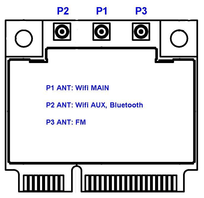
27 5. Antenna port Information -27-
High Performance Mini PCIe Module for Embedded Solution
 802.11ac/abgn Dual-Band 2T2R Mini PCIe Module High Performance Mini PCIe Module for Embedded Solution The is powered by Qualcomm Atheros radio chip and features 2x2 11ac technology for higher throughput
WEPT-232ACN ac/abgn Dual-Band 2T2R Half Mini PCIe Module. Stable Link Quality, Wide Coverage, and Security. Key Feature :
 WPET-232ACN 802.11ac/abgn Dual-Band 2T2R Half Mini PCIe Module Stable Link Quality, Wide Coverage, and Security The WPET-232ACN is powered by Realtek radio chip and features 2x2 11ac/abgn technology for
802.11ac/b/g/n Wi-Fi + Bluetooth M.2 card
 - - - - - - - - - - - - - - - - - - - - - - - - - - - - - - - - - - - - - - - - - - - - - - - - - - - - - - - - - - - - - - - - - - - - - - 802.11ac/b/g/n 802.11ac/b/g/n Feature Standard: 802.11ac/b/g/n
802.11ac/b/g/n Wi-Fi + Bluetooth M.2 card
 - - - - - - - - - - - - - - - - - - - - - - - - - - - - - - - - - - - - - - - - - - - - - - - - - - - - - - - - - - - - - - - - - - - - - - 802.11ac/b/g/n Wi-Fi + Bluetooth 802.11ac/b/g/n Wi-Fi + Bluetooth
WPEQ-353ACNI ac/abgn Dual-Band 3T3R Military Temp Mini PCIe Module. Industrial Wi-Fi transceiver for Military Temp Solution.
 802.11ac/abgn Dual-Band 3T3R Military Temp Mini PCIe Module Industrial Wi-Fi transceiver for Military Temp Solution The is powered by Qualcomm Atheros radio chip and features 3x3 11ac/abgn technology for
802.11a/b/g/n Industrial-Grade Mini Card
 Dual-Band 802.11n 2T2R Industrial-Grade Mini PCIe Module Feature Standard: 802.11a/b/g/n Interface: Mini PCI Express Chipset: Qualcomm Atheros AR9592-AR1B Industrial-Grade Temperature: -40 ~ 85ºC Antenna:
RN-41-SM. Class 1 Bluetooth Socket Module. Features. Applications. Description. Block Diagram. rn-41sm-ds 9/9/2009
 RN-41-SM www.rovingnetworks.com rn-41sm-ds 9/9/2009 Class 1 Bluetooth Socket Module Features Socket module 3/5V DC TTL I/O Fully qualified Bluetooth 2.1/2.0/1.2/1.1 module Bluetooth v2.0+edr support Low
RN-171 Data Sheet. WiFly GSX b/g Wireless LAN Module Features
 WiFly GSX 802.11 b/g Wireless LAN Module Features FCC / CE/ IC certified 2.4GHz IEEE 802.11b/g transceiver Small form factor: 1050 x 700 x 130 mil Controllable output power: 0dBm to 12 dbm RF pad connector
802.11ac/b/g/n Mini Card
 Industry Leading 802.11ac/b/g/n 3T3R Dual-Band Mini PCIe Module Feature Standard: 802.11ac/b/g/n Interface: PCI Express Chipset: Qualcomm Atheros QCA9880 Antenna: 3 x U.FL connectors, 3T3R Data rate up
802.11ac/b/g/n Mini PCI-E Card
 - - - - - - - - - - - - - - - - - - - - - - - - - - - - - - - - - - - - - - - - - - - - - - - - - - - - - - - - - - - - - - - - - - - - - - 802.11ac/b/g/n Mini PCI-E Card Industry Leading 802.11ac/b/g/n
RN-41. Class 1 Bluetooth Module. Features. Applications. Description. Block Diagram. DS-RN41-V3.
 RN-41 www.rovingnetworks.com DS--V3.1 11/13/2009 Class 1 Bluetooth Module Features Fully qualified Bluetooth 2.1/2.0/1.2/1.1 module Bluetooth v2.0+edr support Postage stamp sized form factor, 13.4mm x
RN-21. Class 1 Bluetooth Module. Applications. Features. Description. Block Diagram. DS-RN21-V2 3/25/2010
 RN-21 www.rovingnetworks.com DS-RN21-V2 3/25/2010 Class 1 Bluetooth Module Features Supports Bluetooth 2.1/2.0/1.2/1.1 standards Class1, up to 15dBm(RN21) (100meters) Bluetooth v2.0+edr support Postage
SPBT3.0DP2 module: some technical note about the Radio device embedded in the module, displayed in the Module Block Diagram as STLC2690.
 SPBT3.0DP2 module: some technical note about the Radio device embedded in the module, displayed in the Module Block Diagram as STLC2690. 3 Bluetooth 3.1 Bluetooth functional description 3.1.1 Modem receiver
WiFi b/g/n UART Module
 WiFi 802.11 b/g/n UART Module (Model: WM-SII) (Size: 20mmX15mm) Description WM-SII is a complete IEEE 802.11 b/g/n WiFi module for embedded wireless solution. It is a cost effective and low power solution
RN-42/RN-42-N Data Sheet
 www.rovingnetworks.com DS-RN42-V1.0 2/17/2010 Class 2 Bluetooth Module Features Fully qualified Bluetooth 2.1/2.0/1.2/1.1 module Bluetooth v2.0+edr support Available with on board chip antenna (RN- 42)
U S E R S M A N U A L
 U S E R S M A N U A L C2104001 BCM 43224 WiFi Card Contents SECTION ONE: INTRODUCTION... 3 1. INTRODUCTION... 3 1.1 SCOPE... 3 1.2 FUNCTION... 3 1 2 PRODUCT SPECIFICATION... 4 2.1 HARDWARE SPECIFICATION...
BT50 Datasheet. Amp ed RF Technology, Inc.
 BT50 Datasheet Amp ed RF Technology, Inc. 1 BT50 Product Specification BT50 features Bluetooth features FCC, IC, CE & Bluetooth certified Bluetooth v4.1 Smart Ready Class 1 radio Range up to 80m LOS 1.5Mbps
W-LAN+Bluetooth Combo Module Data Sheet
 Specification Number : SP-ZZ1CK-C W-LAN+Bluetooth Combo Module Data Sheet Broadcom Chipset for 802.11a/b/g/n/ac + Bluetooth 4.0 Tentative P/N : LBEE5ZZ1CK-TEMP Specification Number : SP-ZZ1CK-C 1 / 27
CSR Bluetooth Modules SBC05-AT. Specification. Version July-11
 CSR Bluetooth Modules SBC05-AT Specification Version 1.11 14-July-11 Features: CSR BlueCore05 Chip Bluetooth v2.1 + EDR Class2 S/W Supported : AT command Dimension: 12.5X12.5X2.2mm Slave only Product No.:
RN-42. Class 2 Bluetooth Module. Features. Description. Applications. Block Diagram. DS-RN42-V1.1 1/12/2010.
 www.rovingnetworks.com DS-RN42-V1.1 1/12/2010 Class 2 Bluetooth Module Features Fully qualified Bluetooth 2.1/2.0/1.2/1.1 module Bluetooth v2.0+edr support Postage stamp sized form factor, 13.4mm x 25.8
Integrated a/b/g/n/ac WLAN, Bluetooth & BLE Module
 Integrated 802.11 a/b/g/n/ac WLAN, Bluetooth & BLE Module FEATURES IEEE 802.11 a/b/g/n/ac (single stream n) Typical WLAN Transmit Power: o +16 dbm, 11 Mbps, CCK (b) o +13 dbm, 54 Mbps, OFDM (g) o +11 dbm,
RF4432 wireless transceiver module
 1. Description www.nicerf.com RF4432 RF4432 wireless transceiver module RF4432 adopts Silicon Lab Si4432 RF chip, which is a highly integrated wireless ISM band transceiver. The features of high sensitivity
802.11g Wireless Sensor Network Modules
 RFMProducts are now Murata Products Small Size, Integral Antenna, Light Weight, Low Cost 7.5 µa Sleep Current Supports Battery Operation Timer and Event Triggered Auto-reporting Capability Analog, Digital,
GDM1101: CMOS Single-Chip Bluetooth Integrated Radio/Baseband IC
 GDM1101: CMOS Single-Chip Bluetooth Integrated Radio/Baseband IC General Descriptions The GDM1101 is one of several Bluetooth chips offered by GCT. It is a CMOS single-chip Bluetooth solution with integrated
3V TRANSCEIVER 2.4GHz BAND
 3V TRANSCEIVER 2.4GHz BAND Rev. 2 Code: 32001271 QUICK DESCRIPTION: IEEE 802.15.4 compliant transceiver operating in the 2.4 GHz ISM band with extremely compact dimensions. The module operates as an independent
CSR Bluetooth Modules MB-C05-A2DP MB-C05-AT
 CSR Bluetooth Modules MB-C05-A2DP MB-C05-AT Specification Version 1.07 04-July-09 Features: CSR BlueCore05 Chip Bluetooth v2.0 Compliant Class2 S/W Supported : A2DP Headset Profile Hand Free Profile AVRCP
RN-171 Data Sheet. WiFly GSX b/g Wireless LAN Module. Features
 WiFly GSX 802.11 b/g Wireless LAN Module Features FCC / CE/ IC certified 2.4GHz IEEE 802.11b/g transceiver Small form factor: 1050 x 700 x 130 mil Configurable transmit power: 0dBm to 10 dbm RF pad connector
Characteristic Sym Notes Minimum Typical Maximum Units Operating Frequency Range MHz. RF Chip Rate 11 Mcps RF Data Rates 1, 2, 5.
 RFM Products are now Murata products. Small Size, Light Weight, Low Cost 7.5 µa Sleep Current Supports Battery Operation Timer and Event Triggered Auto-reporting Capability Analog, Digital, Serial and
DNXA-GO1 Specifica on
 DNXA-GO1 Specifica on high-power 802.11 b/g/n 2.4GHz 3x3 PCIe mini card, QCA9381 Overview: DNXA-GO1 is a high-power 802.11 b/g/n 2.4GHz single band 3x3 wifi module in PCIe mini card form factor designed
Single-Chip 5G WiFi IEEE ac MAC/ Baseband/Radio with Integrated Bluetooth 4.1
 Single-Chip 5G WiFi IEEE 802.11ac MAC/ Baseband/Radio with Integrated Bluetooth 4.1 General Description The Cypress single-chip device provides the highest level of integration for Internet of Things and
XTR VF 2.4 HP/V, XTR VF 2.4 HP/H User guide
 XTR VF 2.4 HP/V XTR VF 2.4 HP/H Figure 1: mechanical dimensions (rear view) and photo General description: Long range transceiver XTR VF 2.4 HP/V, XTR VF 2.4 HP/H is pin-to-pin compatible with previous
Secure, Versatile and Award Winning Network Radio Devices.
 Long Range Module (+1 mile) BR-SC40-1W Bluetooth ver2.0+edr OUTLINE AT HOME. AT WORK. ON THE ROAD. USING BLUETOOTH WIRELESS TECHNOLOGY MEANS TOTAL FREEDOM FROM THE CONSTRAINTS AND CLUTTER OF WIRES IN YOUR
ibt-06 Series Bluetooth Module with HCI Interface ( Qualified QDID : B )
") ibt-06 Series ( Qualified QDID : B021756 ) Doc. Name : ibt-06-rev0.5.02.doc Date : 2013-11-21 Revision : 0.5.02 Copyright, 2013 by Engineering Department, Valence Semiconductor Design Limited. All rights
ibt-06 Series ( Qualified QDID : B021756 ) Doc. Name : ibt-06-rev0.5.02.doc Date : 2013-11-21 Revision : 0.5.02 Copyright, 2013 by Engineering Department, Valence Semiconductor Design Limited. All rights
Low Power with Long Range RF Module DATASHEET Description
 Wireless-Tag WT-900M Low Power with Long Range RF Module DATASHEET Description WT-900M is a highly integrated low-power half-'duplex RF transceiver module embedding high-speed low-power MCU and high-performance
SWL-2900U User Guide REV 0.9. Summary. SWL-2900U DatasheetUser Guide. Samsung Electro-Mechanics
 User Guide SWL-2900U User Guide REV 0.9 Samsung Electro-Mechanics 2007-12-26 Summary This document describes the general User-Guide of SWL-2900U IEEE 802.11b/g Wireless LAN USB 2.0 module. 2007 Samsung
SENTRY. AC410x family + BT-V2.0. User s Manual
 SENTRY AC410x family + BT-V2.0 SENTRY TABLE OF CONTENTS 1. INTRODUCTION AND BLOCK DIAGRAM... 2 1.1. GENERAL INTRODUCTION... 2 1.2. BLOCK DIAGRAM... 3 2. MAIN FEATURES AND APPLICATION... 4 2.1. SYSTEM KEY
Applications. Operating Modes. Description. Part Number Description Package. Many to one. One to one Broadcast One to many
 RXQ2 - XXX GFSK MULTICHANNEL RADIO TRANSCEIVER Intelligent modem Transceiver Data Rates to 100 kbps Selectable Narrowband Channels Crystal controlled design Supply Voltage 3.3V Serial Data Interface with
Industrial-grade, high-power n a/b/g wifi 3x3 mini-pci module w/esd and Surge Protection, AR9160-BC1B+AR9106. Model: DNMA-H5
 Industrial-grade, high-power 802.11n a/b/g wifi 3x3 mini-pci module w/esd and Surge Protection, AR9160-BC1B+AR9106 Model: DNMA-H5 DNMA-H5 is an industrial-grade, high-power 802.11n a/b/g wifi 3x3 mini-pci
SNIOT702 Specification. Version number:v 1.0.1
 Version number:v 1.0.1 Catelog 1 Product introduction... 1 1.1 Product introduction... 1 1.2 Product application... 1 1.3 Main characteristics... 2 1.4 Product advantage... 3 2 Technical specifications...
SPECIFICATIONS. MiniPCI g Type IIIB Module Q802MKG2. Ver. 2A Date: 10/26/2006. Prepared by : Qcom Technology Inc.
 SPECIFICATIONS MiniPCI 802.11g Type IIIB Module Q802MKG2 Ver. 2A Date: 10/26/2006 Prepared by : Qcom Technology Inc. Approved by : Specifications of MiniPCI 802.11g Type IIIB Module 2 Contents: 802.11b/g
SV613 USB Interface Wireless Module SV613
 USB Interface Wireless Module SV613 1. Description SV613 is highly-integrated RF module, which adopts high performance Si4432 from Silicon Labs. It comes with USB Interface. SV613 has high sensitivity
Industrial-grade, high-power n a/b/g wifi 3x3 mini-pci module w/esd and Surge Protection, AR9160-BC1B+AR9106. Model: DNMA-H5
 Industrial-grade, high-power 802.11n a/b/g wifi 3x3 mini-pci module w/esd and Surge Protection, AR9160-BC1B+AR9106 Model: DNMA-H5 DNMA-H5 is an industrial-grade, high-power 802.11n a/b/g wifi 3x3 mini-pci
JetWave WIFI Module Industrial 2.4G n 2.4G/ 5G ac mpcie WIFI module
 JetWave WIFI Module Industrial 2.4G 802.11n 2.4G/ 5G 802.11ac mpcie WIFI module User Manual V1.0 Aug. 2016 JetWave WIFI Module User Manual Copyright Copyright 2016 all rights reserved. No part of this
Catalog
 Catalog 1. Description... - 3-2. Features... - 3-3. Application... - 3-4. Electrical specifications...- 4-5. Schematic... - 4-6. Pin Configuration... - 5-7. Antenna... - 6-8. Mechanical Dimension(Unit:
IEEE b/g/n Link Controller Module with Integrated Bluetooth 4.0
 IEEE 802.11 b/g/n Link Controller Module with Integrated Bluetooth 4.0 Description The ATWILC3000-MR110CA module is an IEEE 802.11 b/g/n RF/Baseband/Medium Access Control (MAC) link controller and Bluetooth
RS232-B1 User Manual V1.2 05/10/2017
 RS232-B1 User Manual V1.2 05/10/2017 Table of Contents 1. Introduction...2 1.1 Device Overview... 2 1.2 System Overview... 3 1.3 Features... 3 1.4 Connectors... 4 1.4.1 RS232 Connectors (J1, J2)... 4 1.4.2
UNIGRAND BM7301 Bluetooth HID Module
 KEY FEATURES Bluetooth 3.0 Power Level Class 2 (Max 4dBm) Internal Antenna BQB qualified UNIGRAND BM7301 Bluetooth HID Module Pin-Compatible to the standard legacy BCM2042 module APPLICATIONS Bluetooth
PRODUCT MODULE: GWF-5M01 VERSION: V1.0 DATE:
 IEEE 802.11 a/b/g/n/ac 5.8G/2.4GHz 433Mbps/150Mbps PRODUCT DATASHEET PRODUCT MODULE: GWF-5M01 VERSION: V1.0 DATE: 2015-08-28 SIGNITURE DATE WRITTEN BY VERIFIED BY RATIFIED BY All rights reserved All information
DNMA-H5 Specifica on
 DNMA-H5 Specifica on Industrial-grade, high-power 802.11n a/b/g wifi 3x3 mini-pci module w/esd and Surge Protec on, AR9160-BC1B+AR9106 ESD Overview: DNMA-H5 is an industrial-grade, high-power 802.11n a/b/g
UGWDR82NUH50 Datasheet
 A -UN1 802.11b/g/n WiFi USB Radio Dongle Issue Date: 16-OCT-2009 Revision: 1.0 Re-Tek - 1657-1 - 45388 Warm Springs Blvd. Fremont, CA 94539 REVISION HISTORY Rev. No. History Issue Date Remarks 0.1 Draft
RF4463F30 High Power wireless transceiver module
 RF4463F30 High Power wireless transceiver module 1. Description RF4463F30 adopts Silicon Lab Si4463 RF chip, which is a highly integrated wireless ISM band transceiver chip. Extremely high receive sensitivity
Modulo-2 Data Sheet. Modified: 9 August Afero Part Number: D-LIT
 Modulo-2 Data Sheet Modified: 9 August 2017 Afero Part Number: D-LIT-00029-00 REVISION DATE AUTHOR CHANGE DESCRIPTION 0.5 07/07/17 BB Initial draft 0.6 07/13/17 BB Updated technical specs, updated some
Rayson. Bluetooth Module. Class1 BC04-ext Module. Application. Block Diagram
 Rayson Class1 BC04-ext Module Features Outline Bluetooth Module BTM-22x Bluetooth Ver. 2.0+EDR certification Transmit Power up to +18(class1) Low current consumption: Hold, Sniff, Park, Deep sleep mode
CSR Bluetooth Modules MBC05-CAR-AT
 CSR Bluetooth Modules MBC05-CAR-AT Specification Version 0.1 25-Aug-2009 Product No.: MBC05-CAR-AT Product Description: Bluetooth v2.1 EDR Class 2 BT Stereo Module Issue Date: 2009/08/25 Release Version:
RF NiceRF Wireless Technology Co., Ltd. Rev
 - 1 - Catalog 1. Description...- 3-2. Features...- 3-3. Application...- 3-4. Electrical Specifications...- 4-5. Schematic...- 4-6. Pin Configuration...- 5-7. Antenna... - 6-8. Mechanical dimensions(unit:
DNT24MCA DNT24MPA. Low Cost 2.4 GHz FHSS Transceiver Modules with I/O. DNT24MCA/MPA Absolute Maximum Ratings. DNT24MCA/MPA Electrical Characteristics
 - 2.4 GHz Frequency Hopping Spread Spectrum Transceivers - Direct Peer-to-peer Low Latency Communication - Transmitter RF Power Configurable - 10 or 63 mw - Built-in Chip Antenna - 250 kbps RF Data Rate
TC-3000C Bluetooth Tester
 TC-3000C Bluetooth Tester Product Instructions TC-3000C Bluetooth Tester is able to analyze the data of every packet that is transmitted to the upper application protocol layer using the protocol stack,
HK NATER TECH LIMITED. RL-SM02B-8189ETV Specification RL-SM02B-8189ETV-V1.0
 HK NATER TECH LIMITED RL-SM02B-8189ETV Specification Customer: Description: RL-SM02B-8189ETV-V1.0 Customer P/N: Date: Customer Approve Auditing Admit Provider Approve Auditing Admit Customer: Add: Tel:
VC7300-Series Product Brief
 VC7300-Series Product Brief Version: 1.0 Release Date: Jan 16, 2019 Specifications are subject to change without notice. 2018 Vertexcom Technologies, Inc. This document contains information that is proprietary
Datasheet LT1110 Wireless Module. Version 3.1
 A Version 3.1 REVISION HISTORY Version Date Notes Approver 3.0 13 Jan 2014 Separated into two separate docs: Hardware Integration Guide and User Guide. Marked as Rev 3.0 to match User Guide. Sue White
STLC4560. Single chip b/g WLAN radio. Features. Description. Applications
 Single chip 802.11b/g WLAN radio Data Brief Features Extremely small footprint Ultra low power consumption Fully compliant with the IEEE 802.11b and 802.11g WLAN standards Support for 54, 48, 36, 24, 18,
ESP8089 Datasheet Version 3.4 Copyright 2017
 ESP8089 Datasheet Version 3.4 Copyright 2017 About This Guide This document provides the specifications of ESP8089. Release Notes Date Version Release Notes 2014.12 V1.0 First Release. 2016.08 V2.0 Updated
Embedded Radio Data Transceiver SV611
 Embedded Radio Data Transceiver SV611 Description SV611 is highly integrated, multi-ports radio data transceiver module. It adopts high performance Silicon Lab Si4432 RF chip. Si4432 has low reception
ILI2117 Capacitive Touch Controller
 ILI2117 ILI2117 Capacitive Touch Controller Datasheet Version: V1.01 Release Date: SEP. 09,2015 ILI TECHNOLOGY CORP. 8F, No.38, Taiyuan St., Jhubei City, Hsinchu County 302, Taiwan, R.O.C Tel.886-3-5600099;
Catalog
 - 1 - Catalog 1. Description...- 3-2. Features...- 3-3. Application...- 3-4. Block Diagram...- 3-5. Electrical Characteristics... - 4-6. Operation... - 4-1) Power on Reset...- 4-2) Setting Mode... - 5-3)
User Manual. 1. Introduction. 2. Features
 1. Introduction User Manual AMPAK Technology would like to announce a low-cost and low-power consumption module which has all of the Wi-Fi functionalities. The highly integrated module makes the possibilities
IEEE a/b/g/n 300Mbps WiFi Module. Product Specifications
 IEEE 802.11 a/b/g/n 300Mbps WiFi Module Product Specifications Model: GWF-4M02 Version: 1.1 2017-06-27 Information in this document is subject to change without prior notice. Page 1 of 12 1. Introduction
Class2 BC04-ext Module
 Rayson Class2 BC04-ext Module Features Outline May/2005 Ver.1 Bluetooth Module BTM-110 The module is a Max.4( Class2 ) module. Bluetooth standard Ver. 2.0 conformity. Internal 1.8V regulator Low current
ZigBee OEM Module. ProBee-ZE20S. Datasheet
 1 ZigBee OEM Module ProBee-ZE20S Datasheet Sena Technologies, Inc. Rev 1.0.0 2 ProBee-ZE20S Datasheet Copyright Copyright 2011 Sena Technologies, Inc. All rights reserved. Sena Technologies reserves the
BK8000L Bluetooth Audio SoC User Guide
 BK8000L Bluetooth Audio SoC User Guide F-6688 Brand:XINZHONGXIN FCC ID:2AG94F-6688 Shenzhenshi Xinzhongxin Technology Co., Ltd. Page 1 of 14 BK8000L Datasheet Contents 1. General Description...4 1.1. Features...4
Bluetooth low energy IC. Rev 1.20 TC35679IFTG
 Bluetooth low energy IC Rev 1.20 The Bluetooth word mark and logos are registered trademarks owned by the Bluetooth SIG, Inc. ARM and Cortex are registered trademarks of ARM Limited (or its subsidiaries)
MC-1612 Hardware Design Guide
 LOCOSYS Technology Inc. MC-1612 Hardware Design Guide Version 1.0 Date: 2013/09/17 LOCOSYS Technology Inc. 1 General Rules for Design-in In order to obtain good GPS performances, there are some rules which
Single-Chip Bluetooth Transceiver and Baseband Processor
 Single-Chip Bluetooth Transceiver and Baseband Processor The Cypress CYW20704 is a monolithic, single-chip, Bluetooth 4.1+ HS-compliant, stand-alone baseband processor with an integrated 2.4 GHz transceiver.
TQM679002A Data Sheet
 Block Diagram Rxp Rxn PABC PAEN Tx in Pdetect BTH Balun Product Description PA Directional Detector BTSW RXSW TXSW ANT The TQM679002A is full WLAN/BT front-end module in an ultra small 3mm x 3mm footprint
LM-071 Page Number : 1 of 6. Bluetooth Module Part Code LM-071 Class 2 BC04. Features. General Electrical Specification. Block Diagram RF_I O
 Bluetooth Module Part Code Class 2 BC04 Features Đ The module is a Max.4( Class2 ) module. Đ Đ Low current consumption : Hold,Sniff,Park,Deep sleep Mode Đ 3.0v to 3.6v operation Đ S upport for up to 7
Cypress continues to support existing part numbers. To order these products, please use only the Cypress Ordering Part Number listed in the table.
 The following document contains information on Cypress products. Although the document is marked with the name Broadcom, the company that originally developed the specification, Cypress will continue to
DISCONTINUED. Modulation Type Number of RF Channels 15
 RFM Products are now Murata products. 2.4 GHz Spread Spectrum Transceiver Module Small Size, Light Weight, Built-In Antenna Sleep Current less than 3 µa FCC, Canadian IC and ETSI Certified for Unlicensed
Single Chip High Performance low Power RF Transceiver (Narrow band solution)
") Single Chip High Performance low Power RF Transceiver (Narrow band solution) Model : Sub. 1GHz RF Module Part No : TC1200TCXO-PTIx-N Version : V1.2 Date : 2013.11.11 Function Description The TC1200TCXO-PTIx-N
Single Chip High Performance low Power RF Transceiver (Narrow band solution) Model : Sub. 1GHz RF Module Part No : TC1200TCXO-PTIx-N Version : V1.2 Date : 2013.11.11 Function Description The TC1200TCXO-PTIx-N
TOBY-L1 and MPCI-L1 series
 TOBY-L1 and MPCI-L1 series LTE modules System Integration Manual Abstract This document describes the features and the system integration of TOBY-L1 and MPCI-L1 series LTE cellular modules. These modules
3V DUAL MODE TRANSCEIVER 434 MHz BAND Product Code:
 3V DUAL MODE TRANSCEIVER 434 MHz BAND Product Code: 32001269 Rev. 1.6 PRODUCT SUMMARY: Dual-mode transceiver operating in the 434 MHz ISM band with extremely compact dimensions. The module operates as
DISCONTINUED. Modulation Type Number of RF Channels 15
 RFM products are now Murata Products 2.4 GHz Spread Spectrum Transceiver Module Small Size, Light Weight, Low Cost Sleep Current less than 3 µa FCC, Canadian IC and ETSI Certified for Unlicensed Operation
DNT90MCA DNT90MPA. Low Cost 900 MHz FHSS Transceiver Modules with I/O
 - 900 MHz Frequency Hopping Spread Spectrum Transceivers - Direct Peer-to-peer Low Latency Communication - Transmitter Power Configurable to 40 or 158 mw - Built-in 0 dbi Chip Antenna - 100 kbps RF Data
150Mbps IEEE b/g/n WiFi Module. Product Specifications
 150Mbps IEEE 802.11 b/g/n WiFi Module Product Specifications Model: GWF-7M02 Version: 1.1(Draft) 2014-04-28 Information in this document is subject to change without prior notice. Page 1 of 10 1. Introduction
Cypress continues to support existing part numbers. To order these products, please use only the Cypress Ordering Part Number listed in the table.
 The following document contains information on Cypress products. Although the document is marked with the name Broadcom, the company that originally developed the specification, Cypress will continue to
G3P-R232. User Manual. Release. 2.06
 G3P-R232 User Manual Release. 2.06 1 INDEX 1. RELEASE HISTORY... 3 1.1. Release 1.01... 3 1.2. Release 2.01... 3 1.3. Release 2.02... 3 1.4. Release 2.03... 3 1.5. Release 2.04... 3 1.6. Release 2.05...
Arduino Arduino RF Shield. Zulu 2km Radio Link.
 Arduino Arduino RF Shield RF Zulu 2km Radio Link Features RF serial Data upto 2KM Range Serial Data Interface with Handshake Host Data Rates up to 38,400 Baud RF Data Rates to 56Kbps 5 User Selectable
Bluetooth Module - Part Code LM-072
 Bluetooth Module - Part Code Class 1 BC04 Features Đ Bluetooth Ver. 2.0+EDR certification Đ Transmit Power up to +18(class1) Đ Low current consumption: Hold, Sniff, Park, Deep sleep mode Đ 3.0V to 3.6V
CYW20706 Embedded Bluetooth 4.2 SoC with MCU, Bluetooth Transceiver, and Baseband Processor
 Embedded Bluetooth 4.2 SoC with MCU, Bluetooth Transceiver, and Baseband Processor The Cypress CYW20706 is a monolithic, single-chip, Bluetooth 4.2 + HS compliant SOC, comprising a baseband processor,
Revision History. Rev. No Issued Date Page Description Summary. V Initial Release
 Revision History Rev. No Issued Date Page Description Summary V0.1 2017-06-07 Initial Release 2 List of Contents 1. General... 4 1.1 Overview... 4 1.2 Features... 5 1.3 Application... 5 1.4 Pin Configuration...
KAPPA M. Radio Modem Module. Features. Applications
 KAPPA M Radio Modem Module Features Intelligent RF modem module Serial data interface with handshake Host data rates up to 57,600 baud RF Data Rates to 115Kbps Range up to 500m Minimal external components
E31-TTL-500 Datasheet V Feature E31-TTL-500
 E31-TTL-500 Datasheet V1.0.1.Introduction E31-TTL-500 1.1 Feature E31-TTL-500 E31-TTL-500 is a 500mW wireless transceiver module with narrow-band transmission, operates at 425-450.5MHz (default: 433MHz),
2.4GHZ CMOS WLAN / BT DUAL-MODE RFEIC WITH PA, LNA & SP3T
 2.4GHZ CMOS WLAN / BT DUAL-MODE RFEIC WITH PA, LNA & SP3T ANT DESCRIPTION DET VMODE 1 2 3 16 15 14 13 12 11 10 RFX8425 is a pure CMOS-based, single-chip/single-die RFeIC (RF Front-end Integrated Circuit)
RFFM8216TR7-5K. 2.4 GHz Integrated Wi-Fi Front-End Module
 RFFM8216 2.4 GHz Integrated Wi-Fi Front-End Module Product Overview The RFFM8216 provides a complete integrated solution in a single front end module (FEM) for WiFi 802.11b/g/n/ac systems.performance is
USB Port Medium Power Wireless Module SV653
 USB Port Medium Power Wireless Module SV653 Description SV653 is a high-power USB interface integrated wireless data transmission module, using high-performance Silicon Lab Si4432 RF chip. Low receiver
Preliminary. 4-Channel RTD/4-20 ma Wireless Sensor Node SN24R420-4
 Preliminary - 4 Analog Channel, Battery Powered Wireless Sensor Node - 2 RTD Inputs and 2 4-20 ma Inputs Plus 2 Switch Inputs - Supports 2- and 3-Wire 100 ohm Platinum RTDs - Switch State and Change-of-State
HumPRO TM Series Evaluation Module Data Guide
 HumPRO TM Series Evaluation Module Data Guide ! Warning: Some customers may want Linx radio frequency ( RF ) products to control machinery or devices remotely, including machinery or devices that can cause
DNT2400. Low Cost 2.4 GHz FHSS Transceiver Module with I/O
 2.4 GHz Frequency Hopping Spread Spectrum Transceiver Point-to-point, Point-to-multipoint, Peer-to-peer and Tree-routing Networks Transmitter Power Configurable from 1 to 63 mw RF Data Rate Configurable
SMARTALPHA RF TRANSCEIVER
 SMARTALPHA RF TRANSCEIVER Intelligent RF Modem Module RF Data Rates to 19200bps Up to 300 metres Range Programmable to 433, 868, or 915MHz Selectable Narrowband RF Channels Crystal Controlled RF Design
GAUSS High Power UHF Radio
 [] Table of contents Table of contents... 1 1. Introduction... 3 Features... 4 Block Diagram... 6 2. Pinouts... 7 3. Absolute Maximum Ratings... 9 4. General Recommended Operating Conditions... 10 5. RF
CMOS 2.4GHZ TRANSMIT/RECEIVE WLAN RFeIC
 CMOS 2.4GHZ TRANSMIT/RECEIVE WLAN RFeIC 17 1 RX 2 3 VDD VDD DNC 16 15 14 13 12 11 10 ANT Description The RFX2402C is a fully integrated, single-chip, single-die RFeIC (RF Front-end Integrated Circuit)