AC4490 Hardware Integration Guide Version 4.6
|
|
|
- Dorthy Fisher
- 5 years ago
- Views:
Transcription

1 AC4490 Hardware Integration Guide Version 4.6 Hong Kong:
2 REVISION HISTORY Versio n Date Description Approved By 16 Dec Apr Apr Aug May 2017 Separated into two separate docs (Hardware Integration Guide and User Guide). Information in this document was originally part of the User Guide. Added a Related Documents section. Note: Starting at Rev 4.2 to match the current User Guide. Updated Serial Interface information to: Serial Interface and Digital I/O 3.3V TTL only, all part numbers UART baud rates from 1200 bps to 115,200 bps Updated Serial Interface information to: 3.3V TTL Serial Interface and I/O UART baud rates from 1200 bps to 115,200 bps Added Approved Antenna List Removed references to EOL part numbers Sue White Chris Downey Chris Downey Chris Downey Jonathan Kaye FCC Notice WARNING: This device complies with Part 15 of the FCC Rules. Operation is subject to the following two conditions: (1) This device may not cause harmful interference and (2) This device must accept any interference received, including interference that may cause undesired operation. RF Exposure/Installation Instructions WARNING: To satisfy FCC RF exposure requirements for mobile transmitting devices, this equipment must be professionally installed such that the end user is prevented from replacing the antenna with a non-approved antenna. The end user should also be prevented from being within 20cm of the antenna during normal use with the exception of hands, feet, wrists and ankles. The preceding statement must be included as a CAUTION statement in manuals for OEM products to alert users on FCC RF Exposure compliance. Caution: Any change or modification not expressly approved by Laird could void the user s authority to operate the equipment. 2
3 CONTENTS AC4490 RF Transceiver... 5 Overview... 5 Features... 5 Networking and Security... 5 Easy to Use... 5 Detailed Specifications... 5 Electrical Specifications... 7 Hardware Pin Definitions Pin Descriptions Generic I/O TXD & RXD CTS GND RTS Test RSSI UP_Reset CMD /Data AD In In Range Serial Interface Serial Communications Asynchronous Operation Parity Serial Interface Baud Rate OEM Host Data Rate Radio Interface Protocol Status / Receive Acknowledgement Protocol Status Receive Acknowledgement Flow Control CTS On/CTS On Hysteresis (Flow Control) Security Spread Spectrum History How Spread Spectrum Works Frequency Hopping Spread Spectrum AC4490 Security Features AC4490 Mechanical and Layout Mechanical Drawings AC4490 Timing Diagrams Ordering Information Product Part Number Tree Developer Kit Part Number Compliance Information AC4490-1x
4 Agency Identification Numbers Approved Antenna List FCC / IC Requirements for Modular Approval OEM Equipment Labeling Requirements Antenna Requirements Warnings Required in OEM Manuals Channel Warning Appendix I: 5V to 3.3V Levels Voltage Level Conversion IC s Passive Resistor Voltage Divider Appendix II: Sample Power Supply Bill of Materials Schematic Switching Power Supply PCB Layout Appendix III: Product Throughput Related Documents and Files
5 AC4490 RF TRANSCEIVER The compact AC MHz transceiver can replace miles of cable in harsh industrial environments. Using field-proven frequency hopping spread spectrum (FHSS) technology which needs no additional FCC licensing in the Americas, OEMs can easily make existing systems wireless with little or no RF expertise. Overview The AC4490 is a cost effective, high performance, frequency hopping spread spectrum transceiver designed for integration into OEM systems operating under FCC part regulations for the 900 MHz ISM band. AC4490 transceivers provide an asynchronous TTL level serial interface for OEM Host communications, which include both system and configuration data. The Host supplies system data for transmission to other Host(s). Configuration data is stored in the on-board EEPROM. All frequency hopping, synchronization, and RF system data transmission/reception is performed by the transceiver. To boost data integrity and security, the AC4490 uses Laird s field-proven FHSS technology featuring optional Data-Encryption Standards (DES). Fully transparent, these transceivers operate seamlessly in serial cable replacement applications. AC4490 transceivers can operate in Point-to-Point, Point-to-Multipoint, Client-Server, or Peer-to-Peer architecture. One transceiver is configured as a server with one or many client-configured transceivers synchronized to it. To establish synchronization between transceivers, the server emits a beacon; upon detecting a beacon an RF link is established and a GPIO is toggled to signify to the host that the link is active. This document contains information about the hardware and software interface between a Laird AC4490 transceiver and an OEM Host. Information includes the theory of operation, specifications, interface definition, configuration information and mechanical drawings. The OEM is responsible for ensuring the final product meets all appropriate regulatory agency requirements listed herein before selling any product. Note: Unless mentioned by name, the AC4490 module is referred to as the radio or transceiver. Individual naming is used to differentiate product specific features. The host (PC / Microcontroller / Any device to which the AC4490 module is connected) will be referred to as OEM Host. FEATURES Networking and Security Generic I/O digital lines and integrated DAC/ADC functions Retries and Acknowledgements API Commands to control packet routing and acknowledgement on a packet-by-packet basis Frequency Hopping Spread Spectrum for security and interference rejection Customizable RF Channel number and system ID Dynamic link analysis, remote radio discovery Low latency and high throughput Hardware Protocol Status monitoring Easy to Use Continuous 76.8 Kbps RF data stream Software selectable interface baud rates from 1200 bps to Kbps Low cost, low power and small size ideal for high volume, portable and battery powered applications All modules are qualified for Industrial temperatures (-40 C to 85 C) Advanced configuration available using AT commands DETAILED SPECIFICATIONS Table 1: AC4490 Specification table GENERAL 5
6 20 Pin Interface Connector Molex , mates with Samtec SMM S-D RF Connector MMCX jack Johnson Components AC4490-1x1: Customer must provide Antenna AC : External antenna with MMCX plug or integral antenna AC : External antenna with MMCX plug Serial Interface and I/O Power Consumption (typical) Channels Security Interface Buffer Size 3.3V TTL UART baud rates from 1200 bps to 115,200 bps Duty Cycle (Tx = Transmit, Rx = Receive) Pwrdown 10%Tx 50%Tx 100% 100%Rx Deep Sleep 1x1 33 ma 54 ma 80 ma 28 ma 15 ma 3 ma ma 68 ma 106 ma 30 ma 19 ma 6 ma ma 650 ma 1300 ma 30 ma 19 ma 6 ma 3 Channel Sets comprising 56 total channels. AC4490-1x1: 3 Channel Sets AC : 3 Channel Sets AC : 2 Channel Sets One byte System ID. 56-bit DES encryption key Input/Output: 256 bytes each TRANCEIVER Frequency Band RF Data Rate RF Technology Output Power MHz 76.8 Kbps fixed Frequency Hopping Spread Spectrum (FHSS) Conducted (no antenna) EIRP (3 dbi gain antenna) 1x1 10 mw typical 20 mw typical mw typical 200 mw typical mw typical 1486 mw typical Supply Voltage 1x1 VCC: 3.3 V, ±50 mv ripple VPA: 3.3 V, ±50 mv ripple 200 VCC: V, ±50 mv ripple VPA: V, ±50 mv ripple 1000* VCC: V ±50 mv ripple VPA: 3.3 ±3%, ±100 mv ripple * VCC & VPA may be tied together, provided the supply voltage never falls below 3.3 V and is capable of supplying 1.5 A of current. VCC & VPA are internally connected on the AC only. Sensitivity RF Data Rate Typical 76.8 Kbps -100 dbm 76.8 Kbps (AC4490LR-1000) -110 dbm Note: Receive sensitivity listed for US and Australian modes. Radios ordered per Brazilian regulations have a receive sensitivity of -80 dbm. EEPROM write cycles Hop period 20 ms 6
7 TRANCEIVER Range, Outdoor Line of Site (based on 3dBi gain antenna) 1x1 Up to 1 mile 200 Up to 4 miles 1000 Up to 20 miles LR1000 Up to 40 miles Note: Distance based on US and Australian Modes ENVIRONMENTAL Temperature (Operational) -40 C to +80 C (-40 F to +176 F) Temperature (Storage) -50 C to +85 C (-58 F to +185 F) Humidity (non-condensing) 10% - 90% PHYSICAL Dimensions Transceiver w/ MMCX connector: 1.65 x 1.9 x 0.20 Transceiver w/ integral antenna: 1.65 x 2.65 x 0.20 AC4490-1x1: 1.00 x 1.00 x CERTIFICATIONS AC AC FCC Part KQL-4x90200 KQLAC4490 Industry Canada (IC) 2268C-4x C-AC Caution! ESD Sensitive Component. You must use proper ESD precautions when handling this device to prevent permanent damage. External ESD protection is required to protect this device from damage as required to pass IEC or ISO based on end system application. ELECTRICAL SPECIFICATIONS Table 2: Input Voltage Characteristics Signal Name High Min. AC44901x1 / AC M High Max. Low Min. Low Max. High Min. AC X High Max. Low Min. Low Max. RXD V GI V RTS V Test V GI V UP_RESET V CMD /Data V AD In N/A N/A N/A N/A V Unit 7
8 Table 3: Output Voltage Characteristics Signal Name Module Pin 1x1 Pin Type High Min. Low Max. Unit GO O 8 ma 8 ma V TXD 2 6 O 2 ma 2 ma V Hop Frame 6 1 O 2 ma 2 ma V CTS 7 9 O 2 ma 2 ma V GO O 2 ma 2 ma V RSSI O See Figure 1 See Figure 1 V DA_Out O N/A N/A V 1 In Range O 2 ma 2 ma V 1. DA_Out is an unbuffered, high impedance output and must be buffered by the OEM Host when used. 8
9 Figure 1: Pending RF Buffer Flow 9
10 HARDWARE Pin Definitions The AC4490 has a simple interface that allows OEM host communications with the transceiver and shows the connector pin numbers and associated functions. Table 4: AC4490 Pin Definitions Module Pin 1x1 Pin Type Signal Name Function 1 4 O GO0 Generic Output pin 2 6 O TXD Serial data output from the module to the OEM Host. 3 7 I RXD Serial data input to the module from the OEM Host GI0 Generic Input pin 5 3 GND GND Signal Ground 6 O Hop Frame Pulses low when the transceiver is hopping frequencies. 7 9 O CTS Clear to Send Active Low when the transceiver is ready to accept data for transmission. CTS should be monitored by the OEM Host & data flow to the radio should cease when CTS is High I RTS Request to Send When enabled in EEPROM, the OEM Host can take this High when it is not ready to accept data from the transceiver. Note: Keeping RTS High for too long can cause data loss O GO1 Generic Output pin 10 2 PWR VCC PWR VPA I Test O RSSI Powers the radio and microcontroller. Must be connected. 1x1: 3.3 V, +/- 50 mv ripple 200: V, +/- 50 mv ripple (Pin 10 is internally connected to Pin 11) 1000: V, +/-50mV ripple Powers the power-amplifier and draws most current when in TX mode. Must be connected. 1x1: 3.3 V, +/- 50 mv ripple 200: V, +/- 50 mv ripple (Pin 11 is internally connected to Pin 10) 1000: 3.3 V +/- 3%, +/- 100 mv ripple Test Mode When pulled logic Low and then applying power or resetting, the transceiver s serial interface is forced to a 9600, 8-N- 1 rate. To exit, the transceiver must be reset or power-cycled with Test Mode logic High. Received Signal Strength - An analog output giving an instantaneous indication of received signal strength. Only valid while in Receive Mode I GI1 Generic Input pin I UP_RESET RESET Controlled by the AC4490 for power-on reset if left unconnected. After a stable power-on reset, a logic High pulse will reset the transceiver GND GND Signal Ground 10
11 Module Pin 1x1 Pin Type Signal Name Function I CMD /Data I AD In 10-bit Analog Data Input When logic Low, the transceiver interprets OEM Host data as command data. When logic High, the transceiver interprets OEM Host data as transmit data O DA_Out 10-bit Analog Data Output O In_Range When logic Low, a client is in range of a server on same Channel and System ID. Always low on a server radio. N/A 14 RF RF Port RF Interface N/A 22 I Reset Active Low version of UP_RESET. If RESET is used, UP_RESET should be left floating and if UP_RESET is used, RESET should be left floating. 1. Must be tied to VCC or GND if not used. Should never be permitted to float. 2. If used, requires a shunt 0.1 μf capacitor at pin 15 followed by a series 1 k resistor. 3. If used, requires a series 1 k resistor at pin 20 followed by a shunt 0.1 μf capacitor. Notes: All I/O is 3.3 V TTL with exception of 5 V inputs on AC All inputs are weakly pulled High (10 k) and may be left floating during normal operation. Minimum connections: VCC, VPA, GND, TXD, & RXD. Signal direction depends on the transceiver. Leave unused pins disconnected. 11
12 Pin Descriptions Generic I/O Both GI0/1 pins serve as generic input pins and both GO0/1 pins server as generic output pins. Reading and writing of these pins can be performed using CC Commands. These pins alternatively serve as control pins when modem mode is enabled. TXD & RXD Serial TTL The AC accepts 3.3 or 5 V DC TTL level asynchronous serial data on the RXD pin and interprets that data as either command data or transmit data. Data is sent from the transceiver, at 3.3V levels, to the OEM host via the TXD pin. Note: The AC and AC4490-1x1 transceivers only accept 3.3 V level signals. CTS The AC4490 has an interface buffer size of 256 bytes. If the buffer fills up and more bytes are sent to the transceiver before the buffer can be emptied, data loss occurs. The transceiver prevents this loss by asserting CTS High as the buffer fills up and asserting CTS Low as the buffer is emptied. CTS On and CTS On Hysteresis control the operation of CTS. CTS On specifies the amount of bytes that must be in the buffer for CTS to be disabled (logic High). Even while CTS is disabled, the OEM host can send data to the transceiver, but it should do so carefully. Note: The CTS On and CTS On Hysteresis bytes of the EEPROM can be set to 1, in which case CTS goes high as data is sent in and low when the buffer is empty. GND Signal Ground. Pins are internally connected. RTS With RTS disabled, the transceiver sends any received data to the OEM host when it is received. However, some OEM hosts are not able to accept data from the transceiver all of the time. With RTS enabled, the OEM host can prevent the transceiver from sending data by setting RTS logic High. Once RTS is set logic Low, the transceiver can send packets to the OEM host as they are received. Note: Leaving RTS logic high for too long can cause data loss once the 256 byte receive buffer fills up. Test When pulled logic Low before applying power or resetting, the transceiver s serial interface is forced to 9600 baud, 8-N-1 (8 data bits, No parity, 1 stop bit). To exit, the transceiver must be reset or power-cycled with Test pin logic High. This pin is used to recover transceivers from unknown baud rates only. It should not be used in normal operation. Instead, the transceiver Interface Baud Rate should be programmed to 9600 baud if that rate is desired for normal operation. 12
13 Note: Laird does not recommend permanently grounding the Forced_9600 pin. This mode was intended for recovering transceivers from unknown settings and was not intended to be used in real-time communications. The following modes are affected: Modem mode = disabled Parity mode = disabled Interface Timeout = 0x40 It is also possible that future modes will be disabled by grounding Forced_9600. RSSI Instantaneous RSSI Received Signal Strength Indicator can be used by the OEM Host as an indication of instantaneous signal strength at the receiver. The OEM Host must calibrate RSSI without an RF signal present at the receiver. Calibration is accomplished by following these steps: 1. Power up only one transceiver in the coverage area. 2. Measure the RSSI to obtain the minimum value with no other signal present. 3. Power up another transceiver and begin sending data from that transceiver to the transceiver being measured. Make sure the two transceivers are separated by approximately ten feet. 4. Measure the peak RSSI, while the transceiver is actively receiving data from the remote transceiver, to obtain a maximum value at full signal strength. The following equation approximates the RSSI curve: Signal Strength (dbm) = (-46.9 VRSSI ) 53.9 Figure 2: RSSI Voltage vs. Received Signal Strength Validated RSSI Because RSSI is only valid when the local transceiver is receiving an RF packet from a remote transceiver, instantaneous RSSI is tricky to use. Therefore, the transceiver stores the most recent valid RSSI value. The OEM host issues the Report Last Good RSSI command to request that value. Additionally, validated RSSI can be obtained from Receive Packet and Send Data Complete API commands and from the Probe command. Validated RSSI is not available at the RSSI pin. UP_Reset UP_Reset provides a direct connection to the reset pin on the AC4490 microprocessor and is used to force a soft reset. 13
14 CMD /Data When CMD is held High the transceiver interprets incoming OEM Host data as transmit data to be sent to other transceivers. When CMD Data is held Low the transceiver interprets OEM Host data as command data. AD In AD In can be used as a cost savings to replace Analog-to-Digital converter hardware. Reading of this pin can be performed locally using the Read ADC command. See the AC4490 User Guide for command descriptions. In Range Asserts logic Low when a client transceiver is in range of a server radio operating on the same RF Channel and System ID. If a client cannot hear a server for the amount of time defined by Range Refresh, it will drive In_Range igh and enter search mode looking for a server. When a server is detected, In_Range will always rep In_Range will always report Low on server transceivers. SERIAL INTERFACE For the OEM host and a transceiver to communicate via serial interface they must share a serial data rate. Refer to the following sections to ensure that the OEM host data rate matches the serial interface baud rate. Serial Communications The AC4490 is a TTL device which may connect to a compatible UART (Universal Asynchronous Receiver Transmitter) or level translator to connect to serial devices. The UART mainly transmits or receives serial data. Asynchronous Operation Since there is no separate clock in asynchronous operation, the receiver must use a fixed baud rate and START and STOP bits to synchronize with the transmitter. Figure 3 shows a typical asynchronous mode signal. Figure 3: Asynchronous Mode Signal The UART outputs and inputs logic level signals on the TX and RX pins. The signal is high when no data is being transmitted and low when transmission begins. The signal stays low for the duration of the START bit and is followed by the data bits (LSB first). The STOP bit follows the last data bit and is always high. When the STOP bit finishes, the START bit of the next transmission can occur. Parity A parity bit is used to provide error checking for a single bit error. When a single bit is used, parity can be either even or odd. Even parity means that the number of ones in the data plus the parity equals an even number and vice-versa. The ninth data bit can be used as a parity bit if the data format requires eight data bits and a parity bit as shown in Figure 4. 14
15 Figure 4: Even Parity Bit Note: Enabling parity cuts throughput and the interference buffer in half. Table 5 displays supported asynchronous serial data formats: Table 5: Supported Serial Formats Data Bits Parity Stop Bits Transceiver Programming Requirements 8 N 1 Parity Disabled 7 N 2 Parity Disabled 7 E, O, M, S 1 Parity Disabled 9 N 1 Parity Enabled 8 N 2 Parity Enabled 8 E, O, M, S 1 Parity Enabled 7 E, O, M, S 2 Parity Enabled Mark (M) corresponds to 1 & Space (S) corresponds to 0 Serial Interface Baud Rate This two-byte value determines the baud rate used for communicating over the serial interface between the OEM Host and the transceiver. This rate is independent of the RF baud rate, which is fixed at 76.8 Kbps. Table 6 lists values for some common baud rates. Note: Baud rates below 1200 baud are not supported. For a baud rate to be valid, the calculated baud rate must be within ±3% of the OEM host baud rate. If the Test pin (pin 12) is pulled Logic Low at reset, the baud rate will be forced to For baud rate values other than those shown in Table 6, the following equations can be used: BAUD = Desired Baud BaudH = Always 0 BaudL = Low 8 bits of BAUD (base 16) Table 6: Baud Rate / Interface Timeout Baud Rate BaudL (0x42) BaudH (0x43) Minimum Interface Timeout (0x58) Stop Bit Delay (0x3F) xFE 0x00 0x02 0xFF xFC 0x00 0x02 0x xFA 0x00 0x02 0x08 15
16 Baud Rate BaudL (0x42) BaudH (0x43) Minimum Interface Timeout (0x58) Stop Bit Delay (0x3F) xF8 0x00 0x02 0x0E xF4 0x00 0x03 0x xF0 0x00 0x04 0x xE8 0x00 0x05 0x xD0 0x00 0x09 0x7A xA0 0x00 0x11 0xFC x40 0x00 0x21 0x is the default baud rate 2. 0x00 yields a stop bit of 421 µsec. The stop bit at 1200 baud should be 833 µsec. OEM Host Data Rate The OEM host data rate is the rate with which the OEM host and transceiver communicate over the serial interface. This rate is independent of the RF baud rate, which is fixed at 76.8 Kbps. Possible values range from 1200 bps to bps. RADIO INTERFACE Protocol Status / Receive Acknowledgement Note: Implemented in firmware v6.3 and later. When enabled in EEPROM, GO0 and GO1 perform the functions of Protocol Status and Receive Acknowledgement. Protocol Status Every time the radio hops to hop bin 0, the radio asserts GO0 Low for the entire hop bin. GO0 goes low at the falling edge of the hop frame at the start of bin 0 and goes high with the rising edge of hop frame at the end of bin 0. During all other hops, GO0 is high. Note: This mode is incompatible with Modem mode. Receive Acknowledgement The radio uses GO1 to signal that a valid RF acknowledgement has been received from the remote radio. GO1 is normally low and goes high within approximately 75 µsec of receiving a valid RF acknowledgement. It remains high until the end (rising edge) of the next hop. Note: This mode is incompatible with Modem mode. Flow Control CTS On/CTS On Hysteresis (Flow Control) Flow control refers to the control of data flow between transceivers. It is the method used to handle data in the transmit/receive buffer and determines how data flow between the transceivers is started and stopped. 16
17 Often, one transceiver is capable of sending data at a higher rate than the other can receive it. Flow control allows the slower device to tell the faster device when to pause and resume data transmission. When a transceiver has data to send, it sends a Ready To Send signal and waits for a Clear To Send response from the receiving unit. If the receiving radio is ready to accept data it will assert its CTS low. CTS will be reasserted when the buffer contains the number of bytes specified by CTS_OFF (EEPROM address 0x5D). These signals are sent apart from the data itself on separate wires. Flow control refers to the control of data flow between transceivers. It is the method used to handle data in the transmit/receive buffer and determines how data flow between the transceivers is started and stopped. Often, one transceiver is capable of sending data faster than the other can receive it. Flow control allows the slower device to tell the faster device when to pause and resume data transmission. If RTS Enable is enabled, the receiver will monitor RTS. If the OEM asserts its CTS (transceivers RTS) high, the transceiver will wait to send data over the serial bus to the OEM host until the RTS is asserted low. CTS should be monitored by the OEM host since this is the manner the transceiver signals the OEM Host that it s transmit buffer may be full. If it asserts CTS high, the OEM host should stop sending data over the serial bus. If CTS is asserted low, the OEM host can send data over the serial bus because the transmit buffer is not at its limit. Tip Can I implement a design using just TXD, RXD, and GND (three-wire Interface)? Yes. However, it is strongly recommended that your hardware monitor the CTS pin of the radio. CTS is taken High by the radio when its interface buffer is getting full. Your hardware should stop sending at this point to avoid a buffer overrun (and subsequent loss of data). You can perform a successful design without monitoring CTS. However, you need to take into account the amount of latency the radio adds to the system, any additional latency caused by Transmit Retries or Broadcast Attempts, how often you send data, non-delivery network timeouts and interface data rate. Polled type networks, where the server host requests data from the client host and the client host responds, are good candidates for avoiding the use of CTS. This is because no single transceiver can monopolize the RF link. Asynchronous type networks, where any radio can send to another radio at any point in time, are much more difficult to implement without the use of CTS. 17
18 SECURITY The AC4490 product family utilizes a Frequency Hopping Spread Spectrum (FHSS) technology which provides the foundation for secure digital wireless communications. This section describes how spread spectrum technology works and explains how an OEM can enable specific security features available in the AC4490. Spread Spectrum History Spread Spectrum dates back to World War II when a German scientist was granted a patent on a simple frequency hopping continuous wave (CW) system. The allies also experimented with Spread Spectrum in World War II. These early research and development efforts tried to provide countermeasures for radar, navigation beacons, and communications. The U. S. military has used SS signals over satellites for at least 25 years. How Spread Spectrum Works SS radio communications has long been a favorite technology of the military because it resists jamming and is difficult to intercept. This very same technology is now being widely used in the commercial, industrial, and consumer markets. The reason for this is because SS signals are distributed over a wide range of frequencies and then collected onto their original frequency at the receiver, making them so inconspicuous as to be transparent. Just as they are unlikely to be intercepted by a military opponent, they are also unlikely to interfere with other signals intended for business and consumer users even signals transmitted on the same frequencies. Spread signals are intentionally made to be a much wider band than the information they are carrying and they use special pseudo-noise codes to make them more noise-like. It is this characteristic that makes SS signals difficult to detect, intercept, and demodulate. SS signals are hard to detect on narrowband equipment because the signal's energy is spread over a much wider bandwidth. Further, SS signals are harder to jam (interfere with) than narrowband signals and have a much lower probability to be intercepted, which is why the military has used Spread Spectrum for so many years. The spread of energy over a wide band makes SS signals less likely to interfere with narrowband communications. Narrowband communications, conversely, cause little to no interference to SS systems because the receiver effectively integrates the signal over a wide bandwidth to recover it. Besides being hard to intercept and jam, spread spectrum signals are hard to exploit or imitate. Signal exploitation is the ability of a non-network member to listen to and use information from the network without being a valid network member or participant. Imitation is the act of falsely or maliciously introducing false traffic or messages into a network. SS signals are also more secure than narrowband radio communications. Thus SS signals can have any degree of desired message privacy. Messages can also be encrypted to any level of desired secrecy. The very nature of SS allows military or intelligence levels of privacy and security with minimal complexity. While these characteristics may not be important to everyday business or consumer needs, they are important to understand. Frequency Hopping Spread Spectrum A FHSS radio does what its name implies: it hops from frequency to frequency over a wide band. The specific order in which frequencies are occupied is a function of a code sequence, and the rate of hopping from one frequency to another is a function of the information rate. 18
19 AC4490 Security Features As mentioned at the beginning of this section, the AC4490 uses FHSS technology. In addition, Laird has implemented three levels of security in the AC4490. All three levels of security are associated with their own EEPROM parameter that can programmed for permanent operation or be changed during system operation in volatile memory. The first two levels of security must be configured to establish a network of transceivers and are defined as the Channel Number and System ID. The Channel Number represents a specific hopping sequence and provides physical separation between collocated networks. Thus, all transceivers in a network must be programmed to the same channel number. There are a total of 48 channel numbers. System ID is similar to a password character or network number and makes network eavesdropping more difficult. A receiving radio does not go in range of or communicate with another radio on a different system ID. There are a total of 256 system ID values. If FHSS technology, channel number, and system ID are not enough to secure your data, the AC4490 supports the Data Encryption Standard (DES), which is the third level of security. Encryption is the process of encoding an information bit stream to secure the data content. The algorithm described in this standard specifies both encrypting and decrypting operations which are based on a binary number called a key. A key of 56 bits is used to encrypt and decrypt the data. The encryption algorithm specified in this standard is commonly known among those using the standard. The unique key chosen for use in a particular application makes the results of encrypting data using the algorithm unique. Selection of a different key causes the encrypted data that is produced for any given set of inputs to be different. The cryptographic security of the data depends on the security provided for the key used to encrypt and decrypt the data. Data can be recovered from the encrypted data only by using exactly the same key used to encrypt it. Unauthorized recipients of the encrypted data who know the algorithm but do not have the correct key cannot derive the original data algorithmically. However, anyone who does have the key and the algorithm can easily decrypt the encrypted data and obtain the original data. A standard algorithm based on a secure key thus provides a basis for exchanging encrypted data by issuing the key used to encrypt it to those authorized to have the data. 19
20 AC4490 MECHANICAL AND LAYOUT Mechanical Drawings Interface Connector MMCX Jack 20 pin OEM Interface connector (Molex , mates with Samtec SMM S-D 20 pin OEM Interface connector (Molex , mates with Samtec SMM S-D Figure 5: AC4490 (with MMCX connector) Mechanical 20
21 Figure 6: AC4490-1x1 Mechanical 21

22 Figure 7: AC4490 1x1 PCB Considerations 22
23 AC4490 TIMING DIAGRAMS Figure 8: Addressed Mode with Timeout Figure 9: Addressed Mode with Fixed Packet Length Figure 10: Broadcast Mode with Timeout Figure 11: Broadcast Mode with Fixed Packet Length 23
24 ORDERING INFORMATION Product Part Number Tree Figure 12: Product Part Number Tree Developer Kit Part Number DVK-AC4490LR-1000 Developer s kit includes (2) transceivers, (2) development boards, (2) 7.5 VDC unregulated power supplies, (2) serial cables, (2) USB cables, (2) antennas, downloadable configuration/testing software and integration engineering support. COMPLIANCE INFORMATION AC4490-1x1 Due to the RF antenna trace residing on the OEM Host PCB, the FCC will not grant modular approval for the AC4490-1x1 and requires the OEM to submit their completed design for approval. Contact Laird for the approval procedure. Agency Identification Numbers Agency compliancy is a very important requirement for any product development. Laird has obtained modular approval for its products so the OEM only has to meet a few requirements to be eligible to use that approval. The corresponding agency identification numbers and approved antennas are listed below. Table 7: Agency Identification Numbers 24
25 Part Number US/FCC Canada/IC AC KQL-4x C-4x90200 AC KQL-AC C-AC Approved Antenna List The following antennas are approved for use with the AC4490 as identified. The OEM may choose another vendor s antenna of like type and equal or lesser gain as a listed antenna and still maintain compliance. Table 8: AC4490 Approved Antennas Laird Manufacturer Gain Manufacturer Type Part # Part # (dbi) 200M 200LR 1000M S467FL-5-RMM-915S Nearson 1/2 Wave Dipole 2 X X X S467FL-5-RMM-915 Nearson 1/2 Wave Dipole 2 X X X S467AH-915 Nearson 1/2 Wave Dipole 2 X X X S467AH-915R Nearson 1/2 Wave Dipole 2 X X X S161AH-915R Nearson 1/2 Wave Dipole 2.5 X X X S161AH-915 Nearson 1/2 Wave Dipole 2.5 X X X S331AH-915 Nearson 1/4 Wave Dipole 1 X X X B Flavus gigaant Microstrip Y Comtelco Yagi 6dBd X X X - Y2283A RP Comtelco Yagi 6dBd X X X - SG101N915 1 Nearson Omni 5 X X X - SG101NT-915 Nearson Omni 5 X X X - GM113 V.Torch Omni 3.5 X X - - PC8910NRTN Cushcraft Yagi 11dBd - X - - ANT-DB1-RMS Antenna Factor Monopole 3 X X - 1. Strictly requires professional installation. FCC / IC Requirements for Modular Approval In general, there are two agency classifications of wireless applications: portable and mobile. Portable - Portable is a classification of equipment where the user, in general, will be within 20 cm of the transmitting antenna. Portable equipment is further broken down into two classes: within 2.5 cm of human contact and beyond 2.5 cm. Note: Ankles, feet, wrists, and hands are permitted to be within 2.5 cm of the antenna even if the equipment is designated as being greater than 2.5 cm. The AC4490 is not agency approved for portable applications. The OEM is required to have additional testing performed to receive this classification. Contact Laird for more details. Mobile - Mobile defines equipment where the user will be 20 cm or greater from the transmitting equipment. The antenna must be mounted in such a way that it cannot be moved closer to the user with respect to the equipment, although the equipment may be moved. Note: Ankles, feet, wrists, and hands are permitted to be within 20cm of mobile equipment. 25
26 OEM Equipment Labeling Requirements WARNING: The OEM must ensure that FCC labeling requirements are met. This includes a clearly visible label on the outside of the OEM enclosure specifying the appropriate Laird FCC identifier for this product as well as the FCC notice below. The FCC identifiers are listed above. Contains FCC ID: KQLAC4490 / KQL-4x90200 The enclosed device complies with Part 15 of the FCC Rules. Operation is subject to the following two conditions: (1) This device may not cause harmful interference, and (2) This device must accept any interference received, including interference that may cause undesired operation. Label and text information should be in a size of type large enough to be readily legible, consistent with the dimensions of the equipment and the label. However, the type size for the text is not required to be larger than eight point (8 pt). Antenna Requirements WARNING: This device has been tested with an MMCX connector with the above listed antennas. When integrated into the OEM s product, these fixed antennas require professional installation preventing end-users from replacing them with non-approved antennas. Antenna Y2283 and SG101N915 strictly require professional installation. Any antenna not in the previous table must be tested to comply with FCC Section for unique antenna connectors and Section for emissions. Contact Laird for assistance. Caution: Any change or modification not expressly approved by Laird could void the user's authority to operate the equipment. Warnings Required in OEM Manuals WARNING: This equipment has been approved for mobile applications where the equipment should be used at distances greater than 20 cm from the human body (with the exception of hands, feet, wrists, and ankles). Operation at distances of less than 20 cm is strictly prohibited and requires additional SAR testing. Channel Warning The OEM must prevent the end-user from selecting a channel not approved for use by the governing body in the country in which this product is implemented 26
27 APPENDIX I: 5V TO 3.3V LEVELS All inputs on the AC & AC are weakly pulled High via 10 kohm resistors. The AC has 5 V inputs while the AC & AC4490-1x1 have 3.3 V inputs. The AC uses an octal buffer to drop the 5 V to the required 3.3 V level; the and -1x1 leave this to the OEM. Some of the most common voltage conversion methods are described below. Voltage Level Conversion IC s This is the easiest and most efficient method. Laird recommends the TI SN74LVC244A Octal Buffer/Driver. Inputs can be driven from either 3.3 V or 5 V systems, allowing the device to be used in a mixed 3.3/5 V system. Figure 13: Voltage Level Conversion Passive Resistor Voltage Divider While a resistor voltage divider can successfully drop the 5 V to the required 3.3 V, it will draw static current at all times. Typically, this method is only suitable for one-way 5 V to 3.3 V conversion. When choosing the resistor values, one needs to include the radio s internal 10 kohm resistors on the input signals. 27
28 APPENDIX II: SAMPLE POWER SUPPLY Below is a simple switching power supply that provides enough current to easily power any Laird OEM module. It utilizes low cost, off-the-shelf components that fit into a small area. This supply has an input voltage range of +6 volts to +18 volts and will output +3.4 volts at 1.5 amps. Included is a Bill of Materials with manufacturer s name and part numbers, Schematic and a sample PCB Layout. It is important to follow the layout suggestions and use large areas of copper to connect the devices as shown in the layout. It is also important to hook up the ground traces as shown and use multiple vias to connect input and output capacitors to the bottom side ground plane. If the input voltage is less than 12 volts, C1 and C2 can be replaced with a single 100µF 20 volt capacitor (same part number as C7). This will reduce board space and costs further. If you are powering an AC5124 module, R1 can be changed to a 373 ohm 1% resistor. This will change the output to +5 volts at 1.0 amps. Bill of Materials Table 9: Power Supply Bill of Materials Qty Reference Value Description Mfg. Mfg. Part number 1 R1 210 Res, 0603, 210, 1/16 W, 1% KOA RK73H1JT2100F 1 R2 127 Res, 0603, 127, 1/16 W, 1% KOA RK73H1JT1270F 2 C1 C2 47µF Cap, Tant, 7343, 47 µf, 35 V AVX TPSE476M035R C3 C4 C5 0.1µF Cap, Cer, 0603, 0.1uF, Y5V, 25 V Murata GRM39Y5V104Z025AD 1 C6 3300pF Cap, Cer, 0603, 3300 pf, X7R, 50 V Murata GRM39X7R332K050AD 1 C7 100µF Cap, Tant, 7343, 100 µf, 20 V Kemet T491X107K020A5 1 D1 B230/A Diode, SMB, B230/A, 2A, Schottkey Diodes, Inc. B230/A 1 D2 LL4148 Diode, MELF, LL4148, Switch Diode Diodes, Inc. LL L1 15µH Xfmr, 2P, SMT, 15uH, 2A Coiltronics UP2.8B150 1 U1 CS51413 IC, CS51413, 8P, SO, Switch Reg Ctrl. On-Semicond. CS51413 Schematic Switching Power Supply Figure 14: Power Supply Schematic 28

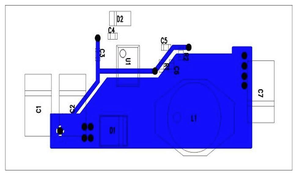
29 PCB Layout Figure 15: PCB Layout Figure 16: PCB Layout 29
30 APPENDIX III: PRODUCT THROUGHPUT Table 10: Product Matrix Part Number AC4490-1x1 AC AC Size 1.0" x 1.0" x 0.125" 1.9" x 1.65" x 0.20" 1.9" x 1.65" x 0.20" Range Up to 1 mile Up to 4 miles Up to 20 miles Throughput 32 Kbps 32 Kbps 32 Kbps Current Draw RX 28 ma 30 ma 30 ma Current Draw TX 80 ma 106 ma 1300 ma Current Draw (Sleep Mode) 15 ma / 3 ma 19 ma / 6 ma 19 ma / 6 ma Chan Band 900 MHz 900 MHz 900 MHz 3.3V Yes Yes Yes Unit Module Module Module Approvals None; needs OEM end approval FCC / IC API Yes Yes Yes Integrated Antenna Available No Yes No FCC / IC 30
31 RELATED DOCUMENTS AND FILES The following additional AC4490 technical documents are also available from the RAMP page under the Product Information tab in the row labelled AC MHz Radio Module: Product Brief AC4490 User Manual Statement of Compliance to EU WEEE Directive and RoHS Directive The following downloads are also available from the RAMP Product Information tab: Laird Configuration Utility USB Drivers AC4490 RF Diagnostic Suite 31
32 Laird Technologies is the world leader in the design and manufacture of customized, performance-critical products for wireless and other advanced electronics applications. Laird Technologies partners with its customers to find solutions for applications in various industries such as: Network Equipment Telecommunications Data Communications Automotive Electronics Computers Aerospace Military Medical Equipment Consumer Electronics Laird Technologies offers its customers unique product solutions, dedication to research and development, as well as a seamless network of manufacturing and customer support facilities across the globe. Copyright 2014 Laird Technologies, Inc. All rights reserved. The information contained in this manual and the accompanying software programs are copyrighted and all rights are reserved by Laird Technologies, Inc. Laird Technologies, Inc. reserves the right to make periodic modifications of this product without obligation to notify any person or entity of such revision. Copying, duplicating, selling, or otherwise distributing any part of this product or accompanying documentation/software without the prior consent of an authorized representative of Laird Technologies, Inc. is strictly prohibited. All brands and product names in this publication are registered trademarks or trademarks of their respective holders. This material is preliminary. Information furnished by Laird Technologies in this specification is believed to be accurate. Devices sold by Laird Technologies are covered by the warranty and patent indemnification provisions appearing in its Terms of Sale only. Laird Technologies makes no warranty, express, statutory, and implied or by description, regarding the information set forth herein. Laird Technologies reserves the right to change specifications at any time and without notice. Laird Technologies products are intended for use in normal commercial and industrial applications. Applications requiring unusual environmental requirements such as military, medical life-support or lifesustaining equipment are specifically not recommended without additional testing for such application. Limited Warranty, Disclaimer, Limitation of Liability 32
AC4790 Hardware Integration Guide Version 2.0
 Version 2.0 Option 2 Hong Kong: +852-2923-0610 REVISION HISTORY Revision Date Description Approved By 1.0 Initial Release Chris Downey 1.1 Changes and Revisions Chris Downey 2.0 19 Dec 2013 Separated (HIG)
CL4790 HARDWARE INTEGRATION GUIDE VERSION 3.0. Americas: Europe: Hong Kong:
 CL4790 HARDWARE INTEGRATION GUIDE VERSION 3.0 Americas: +1-800-492-2320 FCC Notice WARNING: This device complies with Part 15 of the FCC Rules. Operation is subject to the following two conditions: (1)
CL4490 HARDWARE INTEGRATION GUIDE VERSION 1.0. FCC Notice.
 CL4490 HARDWARE INTEGRATION GUIDE VERSION 1.0 wireless.support@lairdtech.com FCC Notice WARNING: This device complies with Part 15 of the FCC Rules. Operation is subject to the following two conditions:
Datasheet LT1110 Wireless Module. Version 3.1
 A Version 3.1 REVISION HISTORY Version Date Notes Approver 3.0 13 Jan 2014 Separated into two separate docs: Hardware Integration Guide and User Guide. Marked as Rev 3.0 to match User Guide. Sue White
CL4790 USER GUIDE VERSION 3.0. Americas: Europe: Hong Kong:
 CL4790 USER GUIDE VERSION 3.0 Americas: +1-800-492-2320 FCC Notice WARNING: This device complies with Part 15 of the FCC Rules. Operation is subject to the following two conditions: (1) This device may
CL024 USER S GUIDE VERSION
 CL024 USER S GUIDE VERSION 1.0 www.lairdtech.com/wireless FCC Notice WARNING: This device complies with Part 15 of the FCC Rules. Operation is subject to the following two conditions: (1) This device may
Contents AC4490 TRANSCEIVER MODULE 1 SPECIFICATIONS 3 THEORY OF OPERATION 7 CONFIGURING THE AC EEPROM PARAMETERS 36 DIMENSIONS 40
 VERSION 3.1 Contents AC4490 TRANSCEIVER MODULE 1 AC4490 features 1 Overview 1 SPECIFICATIONS 3 Pin Definitions 4 Electrical Specifications 6 THEORY OF OPERATION 7 RF Architecture 7 Modes of Operation 7
Contents AC4790 TRANSCEIVER MODULE 1 EEPROM PARAMETERS 32 DIMENSIONS 36 SPECIFICATIONS 3 ORDERING INFORMATION 40 THEORY OF OPERATION 8
 VERSION 1.7 Contents AC4790 TRANSCEIVER MODULE 1 AC4790 features 1 Overview 1 SPECIFICATIONS 3 Pin Definitions 5 Electrical Specifications 7 THEORY OF OPERATION 8 Masterless Architecture 8 Modes of Operation
AC MHz OEM TRANSCEIVERS Specifications Subject to Change
 AC4790 900 MHz OEM TRANSCEIVERS Specifications Subject to Change User s Manual Version 1.3 11160 THOMPSON AVENUE LENEXA, KS 66219 (800) 492-2320 www.aerocomm.com wireless@aerocomm.com 1 DOCUMENT INFORMATION
Frequently Asked Questions ConnexRF Products
 ConnexRF Products Version 1.1 PKLR2400S-200A PKLR2400S-10 LX2400S-3A LX2400S-10 13256 W. 98 TH STREET LENEXA, KS 66215 (800) 492-2320 www.aerocomm.com wireless@aerocomm.com DOCUMENT INFORMATION Copyright
Hardware Integration Guide RM024 RAMP Wireless Module. Version 3.4
 A RM024 RAMP Wireless Module Version 3.4 REVISION HISTORY Version Date Notes Approver 1.0 Initial Release Chris Downey 2.1 Added firmware changes, updated the name of the Force 9600 Pin, removed old references
AC MHz OEM TRANSCEIVERS Specifications Subject to Change
 AC4490 900 MHz OEM TRANSCEIVERS Specifications Subject to Change User s Manual Version 2.3 11160 THOMPSON AVENUE LENEXA, KS 66219 (800) 492-2320 www.aerocomm.com wireless@aerocomm.com DOCUMENT INFORMATION
Receiver 10-5 BER -100 dbm Transmitter RF Output Power 1 10 or 63 mw mw Antenna Impedance 50 Ω
 - 2.4 GHz Frequency Hopping Spread Spectrum Transceivers - Direct Peer-to-peer Low Latency Communication - Transmitter RF Power Configurable - 10 or 63 mw - Transmitter EIRP 15.8 mw or 100 mw with 2 dbi
RM24100A. Introduction. 1 Features. 2.4GHz 100mW RS232 / RS485 / RS422 DSSS Radio Modem (IEEE compliant) Operating Manual English 1.
 Operating Manual English 1.") RM24100A 2.4GHz 100mW RS232 / RS485 / RS422 DSSS Radio Modem (IEEE 802.15.4 compliant) Operating Manual English 1.03 Introduction The RM24100A radio modem acts as a wireless serial cable replacement and
RM24100A 2.4GHz 100mW RS232 / RS485 / RS422 DSSS Radio Modem (IEEE 802.15.4 compliant) Operating Manual English 1.03 Introduction The RM24100A radio modem acts as a wireless serial cable replacement and
Datasheet RM024 RAMP Wireless Module. Version 3.9
 A RM024 RAMP Wireless Module Version 3.9 REVISION HISTORY Version Date Notes Approver 1.0 Initial Release Chris Downey 2.1 Added firmware changes, updated the name of the Force 9600 Pin, removed old references
RM24100D. Introduction. 1 Features. 2.4GHz 100mW RS232 / RS485 / RS422 DSSS Radio Modem (IEEE compliant) Operating Manual English 1.
 Operating Manual English 1.") RM24100D 2.4GHz 100mW RS232 / RS485 / RS422 DSSS Radio Modem (IEEE 802.15.4 compliant) Operating Manual English 1.03 Introduction The RM24100D radio modem acts as a wireless serial cable replacement and
RM24100D 2.4GHz 100mW RS232 / RS485 / RS422 DSSS Radio Modem (IEEE 802.15.4 compliant) Operating Manual English 1.03 Introduction The RM24100D radio modem acts as a wireless serial cable replacement and
900 MHz. Frequency Hopping RS-485 Master/Slave auto-sensing radio interface.
 MDR210A-485 900 MHz. Frequency Hopping RS-485 Master/Slave auto-sensing radio interface. Black Box Corporation Lawrence, PA - http://www.blackbox.com - Ph 877-877-BBOX - Fax 724-746-0746 Table of Contents
DNT90MCA DNT90MPA. Low Cost 900 MHz FHSS Transceiver Modules with I/O
 - 900 MHz Frequency Hopping Spread Spectrum Transceivers - Direct Peer-to-peer Low Latency Communication - Transmitter Power Configurable to 40 or 158 mw - Built-in 0 dbi Chip Antenna - 100 kbps RF Data
CL4424. Industrial 2.4GHz ConnexLink. User s Manual Version 1.1
 CL4424 Industrial 2.4GHz ConnexLink User s Manual Version 1.1 11160 THOMPSON AVENUE LENEXA, KS 66215 (800) 492-2320 www.aerocomm.com sales@aerocomm.com Document Information Copyright Information Copyright
MDR24x Wireless 2.4GHz Modem
 MDR24x Wireless 2.4GHz Modem User s Manual Version 1.1 1000 Park Drive Lawrence, PA 15055-1018 Website: www.blackbox.com Email: info@blackbox.com Order Toll Free in the US: Call 877-877-BBOX (Outside the
DNT24MCA DNT24MPA. Low Cost 2.4 GHz FHSS Transceiver Modules with I/O. DNT24MCA/MPA Absolute Maximum Ratings. DNT24MCA/MPA Electrical Characteristics
 - 2.4 GHz Frequency Hopping Spread Spectrum Transceivers - Direct Peer-to-peer Low Latency Communication - Transmitter RF Power Configurable - 10 or 63 mw - Built-in Chip Antenna - 250 kbps RF Data Rate
DNT90MC DNT90MP. Low Cost 900 MHz FHSS Transceiver Modules with I/O
 - 900 MHz Frequency Hopping Spread Spectrum Transceivers - Direct Peer-to-peer Low Latency Communication - Transmitter Power Configurable to 40 or 158 mw - 100 kbps RF Data Rate - Serial Port Data Rate
RM24100A. *Maximum transmit power output levels and local radio frequency regulator bodies must be obeyed in the country of operation.
 RM24100A 2.4GHz 100mW RS232 / RS485 / RS422 DSSS Radio Modem (IEEE 802.15.4 compliant) Operating Manual English 1.02 Introduction The RM24100A radio modem acts as a wireless serial cable replacement and
DNT900. Low Cost 900 MHz FHSS Transceiver Module with I/O
 DEVELOPMENT KIT (Info Click here) 900 MHz Frequency Hopping Spread Spectrum Transceiver Point-to-point, Point-to-multipoint, Peer-to-peer and Tree-routing Networks Transmitter Power Configurable from 1
DNT2400. Low Cost 2.4 GHz FHSS Transceiver Module with I/O
 2.4 GHz Frequency Hopping Spread Spectrum Transceiver Point-to-point, Point-to-multipoint, Peer-to-peer and Tree-routing Networks Transmitter Power Configurable from 1 to 63 mw RF Data Rate Configurable
NL900PRO. User Manual Version B0. Radio Data Modem. With Selectable RS232 RS485 RS422
 NL900PRO User Manual Version B0 Radio Data Modem With Selectable RS232 RS485 RS422 7610 MIRAMAR ROAD San Diego, CA 92126 (800) 233-1728 www.rfneulink.com sales@rfneulink.com D O CUME NT I N FORMA TION
SMARTALPHA RF TRANSCEIVER
 SMARTALPHA RF TRANSCEIVER Intelligent RF Modem Module RF Data Rates to 19200bps Up to 300 metres Range Programmable to 433, 868, or 915MHz Selectable Narrowband RF Channels Crystal Controlled RF Design
RF Engine Model RF100 Part Numbers: RF100PC6 and RF100PD6 Document Revision v1.0
 DATA SHEET RF Engine Model RF100 Part Numbers: RF100PC6 and RF100PD6 Document Revision v1.0 2011 Synapse, All Rights Reserved All Synapse products are patented or patent pending Specifications are subject
RM24100D. Introduction. Features. 2.4GHz 100mW RS232 / RS485 / RS422 DSSS Radio Modem (IEEE compliant) Operating Manual English 1.
 Operating Manual English 1.") RM24100D 2.4GHz 100mW RS232 / RS485 / RS422 DSSS Radio Modem (IEEE 802.15.4 compliant) Operating Manual English 1.09 Introduction The RM24100D radio modem acts as a wireless serial cable replacement and
RM24100D 2.4GHz 100mW RS232 / RS485 / RS422 DSSS Radio Modem (IEEE 802.15.4 compliant) Operating Manual English 1.09 Introduction The RM24100D radio modem acts as a wireless serial cable replacement and
CDR-915 Data Radio Module INTEGRATOR S GUIDE
 CDR-915 Data Radio Module Coyote DataCom, Inc. 3941 Park Drive, Suite 20-266, El Dorado Hills, CA 95762 Tel. 916-933-9981 Fax 916-913-0951 www.coyotedatacom.com TABLE OF CONTENTS General Information and
RAMP Wireless Module RM024. User Manual Version 2.1
 RAMP Wireless Module RM024 User Manual Version 2.1 CONTENTS RAMP Modules... 3 Overview... 3 Key Features... 3 Detailed Specifications... 4 Pin Definitions... 5 Input Characteristics... 8 Output Characteristics...
Revision WI.232FHSS-25-FCC-R and RK-WI.232FHSS-25-FCC-R USER S MANUAL
 Revision 1.0.3 WI.232FHSS-25-FCC-R and RK-WI.232FHSS-25-FCC-R USER S MANUAL RADIOTRONIX, INC. WI.232FHSS-25-FCC-R/ RK-WI.232FHSS-25-FCC-R USER S MANUAL Radiotronix 905 Messenger Lane Moore, Oklahoma 73160
802.11g Wireless Sensor Network Modules
 RFMProducts are now Murata Products Small Size, Integral Antenna, Light Weight, Low Cost 7.5 µa Sleep Current Supports Battery Operation Timer and Event Triggered Auto-reporting Capability Analog, Digital,
LT2510 WIRELESS MODULE
 WIRELESS MODULE USER MANUAL Version 1.5 www.lairdtech.com Innovative Technology for a Connected World Laird Technologies is the world leader in the design and manufacture of customized, performance-critical
DISCONTINUED. Modulation Type Number of RF Channels 15
 RFM products are now Murata Products 2.4 GHz Spread Spectrum Transceiver Module Small Size, Light Weight, Low Cost Sleep Current less than 3 µa FCC, Canadian IC and ETSI Certified for Unlicensed Operation
SmartRadio Transmitter / Receiver
 Easy to use Radio Transmitter & Receivers AM Radio Hybrid Technology Supports Data or Telemetry communications Simple CMOS/TTL Data Interface Automatic data encryption / decryption Host Interface up to
CL2510 RF Transceiver
 USER MANUAL Version 1.4 www.lairdtech.com Innovative Technology for a Connected World Laird Technologies is the world leader in the design and manufacture of customized, performance-critical products for
SPECIAL SPECIFICATION 6744 Spread Spectrum Radio
 2004 Specifications CSJ 0924-06-244 SPECIAL SPECIFICATION 6744 Spread Spectrum Radio 1. Description. Furnish and install spread spectrum radio system. 2. Materials. Supply complete manufacturer specifications
Characteristic Sym Notes Minimum Typical Maximum Units Operating Frequency Range MHz. RF Chip Rate 11 Mcps RF Data Rates 1, 2, 5.
 RFM Products are now Murata products. Small Size, Light Weight, Low Cost 7.5 µa Sleep Current Supports Battery Operation Timer and Event Triggered Auto-reporting Capability Analog, Digital, Serial and
2W UHF MHz Radio Transceiver
 2W UHF410-470 MHz Radio Transceiver Specification Copyright Javad Navigation Systems, Inc. February, 2006 All contents in this document are copyrighted by JNS. All rights reserved. The information contained
Preliminary. DN-900 Series. 900 MHz Wireless Serial Modems
 Preliminary - 900 MHz RS-232C, RS-485/RS-232C and USB Serial Modems - Optional 128-Bit AES Encryption - Point-to-point, Point-to-multipoint, Peer-to-peer and Tree-routing Network Capabilities - Frequency
User Guide LT1110. Version 3.4
 A Version 3.4 REVISION HISTORY Version Date Notes Approver 1.0 8 Oct 2010 Initial Release Chris Downey 1.1 6 May 2011 Full release for FW v2.9-0 Chris Downey 1.2 (undocumented) Chris Downey 2.0 12 Nov
DISCONTINUED. Modulation Type Number of RF Channels 15
 RFM Products are now Murata products. 2.4 GHz Spread Spectrum Transceiver Module Small Size, Light Weight, Built-In Antenna Sleep Current less than 3 µa FCC, Canadian IC and ETSI Certified for Unlicensed
Preliminary. RF Data Transmission Rates 38.4, 115.2, 200 and 500 kbps
 Preliminary - 2.4 GHz RS-232C, RS-485/RS-232C and USB Serial Modems - Optional 128-Bit AES Encryption - Point-to-point, Point-to-multipoint, Peer-to-peer and Tree-routing Network Capabilities - Frequency
HumPRO TM Series Evaluation Module Data Guide
 HumPRO TM Series Evaluation Module Data Guide ! Warning: Some customers may want Linx radio frequency ( RF ) products to control machinery or devices remotely, including machinery or devices that can cause
AT-XTR-7020A-4. Multi-Channel Micro Embedded Transceiver Module. Features. Typical Applications
 AT-XTR-7020A-4 Multi-Channel Micro Embedded Transceiver Module The AT-XTR-7020A-4 radio data transceiver represents a simple and economical solution to wireless data communications. The employment of an
Applications. Operating Modes. Description. Part Number Description Package. Many to one. One to one Broadcast One to many
 RXQ2 - XXX GFSK MULTICHANNEL RADIO TRANSCEIVER Intelligent modem Transceiver Data Rates to 100 kbps Selectable Narrowband Channels Crystal controlled design Supply Voltage 3.3V Serial Data Interface with
ECOS SRIF Operating Instructions
 ECOS SRIF 2002 Operating Instructions Edition 10/2003 Safety instructions This document contains instructions you are strongly advised to observe in order to guarantee your personal safety and to avoid
G3P-R232. User Manual. Release. 2.06
 G3P-R232 User Manual Release. 2.06 1 INDEX 1. RELEASE HISTORY... 3 1.1. Release 1.01... 3 1.2. Release 2.01... 3 1.3. Release 2.02... 3 1.4. Release 2.03... 3 1.5. Release 2.04... 3 1.6. Release 2.05...
Radiocrafts Embedded Wireless Solutions
 Wireless M-Bus High power N Mode RF Transceiver Module EN 13757-4:2013) Product Description The RC1701HP-MBUS is part of a compact surface-mounted Wireless M-Bus module family that measures only 12.7 x
Low Power with Long Range RF Module DATASHEET Description
 Wireless-Tag WT-900M Low Power with Long Range RF Module DATASHEET Description WT-900M is a highly integrated low-power half-'duplex RF transceiver module embedding high-speed low-power MCU and high-performance
DN-90 Series. 900 MHz Wireless Serial Modems
 - 900 MHz RS-232C and RS-232C/RS-485 Serial Modems - Optional 128-Bit AES Encryption - Point-to-point,Point-to-multipoint, Peer-to-peer and Store & Forward Capabilities - Frequency Hopping Spread Spectrum
Arduino Arduino RF Shield. Zulu 2km Radio Link.
 Arduino Arduino RF Shield RF Zulu 2km Radio Link Features RF serial Data upto 2KM Range Serial Data Interface with Handshake Host Data Rates up to 38,400 Baud RF Data Rates to 56Kbps 5 User Selectable
BT50 Datasheet. Amp ed RF Technology, Inc.
 BT50 Datasheet Amp ed RF Technology, Inc. 1 BT50 Product Specification BT50 features Bluetooth features FCC, IC, CE & Bluetooth certified Bluetooth v4.1 Smart Ready Class 1 radio Range up to 80m LOS 1.5Mbps
3V TRANSCEIVER 2.4GHz BAND
 3V TRANSCEIVER 2.4GHz BAND Rev. 2 Code: 32001271 QUICK DESCRIPTION: IEEE 802.15.4 compliant transceiver operating in the 2.4 GHz ISM band with extremely compact dimensions. The module operates as an independent
Catalog
 - 1 - Catalog 1. Overview... - 3-2. Feature...- 3-3. Application... - 3-4. Block Diagram... - 3-5. Electrical Characteristics...- 4-6. Operation...- 4-1) Power on Reset... - 4-2) Sleep mode...- 4-3) Working
Alpha RF900 Wireless Transceiver Signal Strength Software Instructions
 Alpha RF900 Wireless Transceiver Signal Strength Software Instructions Introduction This document explains how to use the diagnostic signal strength software to tell if there is an acceptable wireless
KAPPA M. Radio Modem Module. Features. Applications
 KAPPA M Radio Modem Module Features Intelligent RF modem module Serial data interface with handshake Host data rates up to 57,600 baud RF Data Rates to 115Kbps Range up to 500m Minimal external components
Datasheet. Bluetooth Smart Module. Pacwave Bluetooth Smart (BLE) Module DESCRIPTION FEATURES
 Module DESCRIPTION FEATURES") Pacwave Bluetooth Smart (BLE) Module FEATURES Built in CSR μenergy CSR1010 Bluetooth Smart (v4.1) chipset +7.5dBm Maximum RF Transmit Output Power 92.5dBm RF Receive Sensitivity RSSI Monitoring Built in
Pacwave Bluetooth Smart (BLE) Module FEATURES Built in CSR μenergy CSR1010 Bluetooth Smart (v4.1) chipset +7.5dBm Maximum RF Transmit Output Power 92.5dBm RF Receive Sensitivity RSSI Monitoring Built in
BluetoothMesh ModuleDatasheet
 BluetoothMesh ModuleDatasheet (WS_D02_8266_V2.2) Shenzhen WE SMART Electronics Co., Ltd Website:www.we smart.cn Mailbox:business@we smart.cn Address:7th FL,Bldg 2B,Wu tong dao industrial park,hangkong
868MHz HumDT TM Series RF Transceiver Module Data Guide
 868MHz HumDT TM Series RF Transceiver Module Data Guide ! Warning: Some customers may want Linx radio frequency ( RF ) products to control machinery or devices remotely, including machinery or devices
SV613 USB Interface Wireless Module SV613
 USB Interface Wireless Module SV613 1. Description SV613 is highly-integrated RF module, which adopts high performance Si4432 from Silicon Labs. It comes with USB Interface. SV613 has high sensitivity
E31-TTL-500 Datasheet V Feature E31-TTL-500
 E31-TTL-500 Datasheet V1.0.1.Introduction E31-TTL-500 1.1 Feature E31-TTL-500 E31-TTL-500 is a 500mW wireless transceiver module with narrow-band transmission, operates at 425-450.5MHz (default: 433MHz),
HumDT TM Series RF Transceiver Module Data Guide
 HumDT TM Series RF Transceiver Module Data Guide ! Warning: Some customers may want Linx radio frequency ( RF ) products to control machinery or devices remotely, including machinery or devices that can
TRXQ1 RXQ1 FM NARROW BAND TRANSCEIVERS. RXQ1 Version. Applications. TRXQ1 Version
 RF Transceiver or Intelligent Modem Versions Host Data Rate upto 19,200 Baud Data Rates to 20 K baud. 2 Selectable RF Channels Narrowband Crystal Controlled Optimal Range 200m Supply Voltage 3-5V Very
Complete 2.4 GHz RF Transceiver Module with Built-In RFDP8 Application Protocol Part Numbers RFD21733, RFD21735, RFD21737, RFD21738, RFD21739
 Complete 2.4 GHz RF Transceiver Module with Built-In Application Protocol Part Numbers,,,, Optional Configuration For use with External Antenna 15mm x 15mm (0.600 inch x 0.600 inch) / is a complete, READY-TO-USE
Wireless Reading of Sensirion Sensors By H. Moholdt
 Wireless Reading of Sensirion Sensors By H. Moholdt Abstract By using an off-the-shelf RF module, wireless reading of pressure-, humidity- and temperature can be achieved with a very limited design effort.
E70-433MS14 Datasheet v1.1
 E70-433MS14 Datasheet v1.1 Contents 1. Introduction... 2 2. Features... 3 3. E70 Series... 3 4. Electrical Parameter... 4 5. UART Functional description (default)... 5 5.1 Fixed transmission... 5 5.2 Broadcast
HumPRC TM Series Evaluation Module Data Guide
 HumPRC TM Series Evaluation Module Data Guide ! Warning: Some customers may want Linx radio frequency ( RF ) products to control machinery or devices remotely, including machinery or devices that can cause
Embedded Radio Data Transceiver SV611
 Embedded Radio Data Transceiver SV611 Description SV611 is highly integrated, multi-ports radio data transceiver module. It adopts high performance Silicon Lab Si4432 RF chip. Si4432 has low reception
CONTROL MICROSYSTEMS SCADAWave Radio Transceiver. Hardware Manual
 5908 SCADAWave Radio Transceiver Hardware Manual CONTROL MICROSYSTEMS SCADA products... for the distance 48 Steacie Drive Telephone: 613-591-1943 Kanata, Ontario Facsimile: 613-591-1022 K2K 2A9 Technical
RFD900x Radio Modem Data Sheet MHz frequency band
 RFD900x Radio Modem Data Sheet 902-928MHz frequency band Product Specifications and Performance Flash Programmer User Manual Features Out of the box RF communications. Air data rate speeds of up to 750kbps
Lifetime Power Energy Harvesting Development Kit for Wireless Sensors User s Manual - featuring PIC MCU with extreme Low Power (XLP) Technology
 Technology") P2110-EVAL-01 Lifetime Power User s Manual - featuring PIC MCU with extreme Low Power (XLP) Technology Overview The Lifetime Power is a complete demonstration and development platform for creating battery-free
P2110-EVAL-01 Lifetime Power User s Manual - featuring PIC MCU with extreme Low Power (XLP) Technology Overview The Lifetime Power is a complete demonstration and development platform for creating battery-free
AcuMesh Wireless RS485 Network. User's Manual SOLUTION
 AcuMesh Wireless RS485 Network User's Manual AN SOLUTION ACUMESH - WIRELESS METERING SYSTEM COPYRIGHT 2015 V1.2 This manual may not be altered or reproduced in whole or in part by any means without the
Purchase the sample:http://www.aliexpress.com/store/ E32-TTL-100 Datasheet V Feature E32-TTL-100
 E32-TTL-100 Datasheet V1.0.1.Introduction E32-TTL-100 1.1 Feature E32-TTL-100 E32-TTL-100 is a wireless transceiver module with LoRa spread-spectrum technology, operates at 434MHz, based on original imported
XCite OEM RF Module. Product Manual v South 520 West, Suite 180 Lindon, UT Phone: (801) Fax: (801)
 Fax: (801)") XCite OEM RF Module XCite OEM RF Module Data Radio System Components RF Module Configuration Appendices Product Manual v1.1 For XCite OEM RF Module Part Numbers: XC09-009 XC09-038 355 South 520 West, Suite
XCite OEM RF Module XCite OEM RF Module Data Radio System Components RF Module Configuration Appendices Product Manual v1.1 For XCite OEM RF Module Part Numbers: XC09-009 XC09-038 355 South 520 West, Suite
OEM 100. User Manual. Figure 1: OEM 100 Module with HG Rectangular Antenna Board
 OEM 100 User Manual Figure 1: OEM 100 Module with HG Rectangular Antenna Board Revision History Revision History Release Version Date Revision Description Authors Version 1.0 07/20/09 Initial Release Bryan
3V DUAL MODE TRANSCEIVER 434 MHz BAND Product Code:
 3V DUAL MODE TRANSCEIVER 434 MHz BAND Product Code: 32001269 Rev. 1.6 PRODUCT SUMMARY: Dual-mode transceiver operating in the 434 MHz ISM band with extremely compact dimensions. The module operates as
Characteristic Sym Notes Minimum Typical Maximum Units Operating Frequency Range MHz Operating Frequency Tolerance khz
 DEVELOPMENT KIT (Info Click here) 2.4 GHz ZigBee Transceiver Module Small Size, Light Weight, +18 dbm Transmitter Power Sleep Current less than 3 µa FCC and ETSI Certified for Unlicensed Operation The
RN-41-SM. Class 1 Bluetooth Socket Module. Features. Applications. Description. Block Diagram. rn-41sm-ds 9/9/2009
 RN-41-SM www.rovingnetworks.com rn-41sm-ds 9/9/2009 Class 1 Bluetooth Socket Module Features Socket module 3/5V DC TTL I/O Fully qualified Bluetooth 2.1/2.0/1.2/1.1 module Bluetooth v2.0+edr support Low
TS4000 Radio Modem. User s Manual
 TS4000 Radio Modem User s Manual Version 6.60C 1729 South Main Street Milpitas, CA 95035 (408) 941-1808 (800) 663-3674 (408) 941-1818 Fax www.teledesignsystems.com productsales@teledesignsystems.com techsupport@teledesignsystems.com
Catalogue
 - 1 - Catalogue 1. Description... - 3-2. Features... - 3-3. Applications...- 3-4. Block Diagram... - 3-5. Electrical Characteristics...- 4-6. Operation...- 5 - Power on Reset... - 5 - Working mode... -
ORiNOCO AP-4000MR-LR and AP-4900MR-LR Access Points Safety and Regulatory Compliance Information
 IMPORTANT! Visit http://support.proxim.com for the latest safety and regulatory compliance information for this product. ORiNOCO AP-4000MR-LR and AP-4900MR-LR Access Points Safety and Regulatory Compliance
RF RECEIVER DECODER RDF1. Features Complete FM Receiver and Decoder. Applications
 Features Complete FM Receiver and Decoder. Small Form Factor Range up to 200 Metres* Easy Learn Transmitter Feature. Learns 40 transmitter Switches 4 Digital and 1 Serial Data outputs Outputs, Momentary
CONDOR C1722 GPS RECEIVER MODULE technical notes
 CONDOR C1722 GPS RECEIVER MODULE TECHNICAL HIGHLIGHTS Receiver: GPS L1 frequency (1575.42 MHz), C/A code, 22-channel continuous tracking NMEA output and input: serial port, USB port On-board low noise
Specification Sym Notes Minimum Typical Maximum Units 900 MHz Operating Frequency Range MHz
 900 MHz FHSS DNT90/Ethernet Gateway Optional 128-Bit AES Encryption Point-to-point, Point-to-multipoint or Store and Forward Operation 158 mw EIRP 900 MHz Transmitter Power 10/100Base-T Auto-sensing Ethernet
Characteristic Sym Notes Minimum Typical Maximum Units Operating Frequency Range MHz Operating Frequency Tolerance khz
 DEVELOPMENT KIT (Info Click here) 2.4 GHz ZigBee Transceiver Module Small Size, Light Weight, Low Cost Sleep Current less than 3 µa FCC and ETSI Certified for Unlicensed Operation The ZMN2405 2.4 GHz transceiver
RF ISM Transparent Transceiver Module V4.0
 RF7020-27 ISM Transparent Transceiver Module V4.0 Overview: RF7020-27 is highly integrated semi-duplex medium power transceiver module with high speed MCU and high performance RF IC. Utilizing high efficiency
Wireless Communications Module Stand-Alone HE200WCM910 and SmartStack HE800WCM900 / HE-WCM900* * HE- denotes plastic case.
 MAN0783-01 15 JUN 2005 PAGE 1 This datasheet also covers products starting with IC300 instead of HE800 or HE-. Additional technical information is found in the following supplements: HE200WCM910 (MAN0782)
NMEA Protocol Converter 2 Plus 3 Users Guide
 NMEA Protocol Converter 2 Plus 3 Constellation Data Systems, Inc. 10296 Springfield Pike Cincinnati, OH 45215 Phone: (513) 984-4491 Fax: (513) 984-4896 Web: www.constellationdata.com Copyright 2006 Constellation
SV-MESH Mesh network series Catalogue
 Catalogue 1. Description... 3 2. Features... 3 3. Applications... 3 4. Block Diagram... 4 5. Electrical Characteristics... 5 6. Operation... 5 Power on Reset... 5 Working mode... 6 Router mode... 8 Setting
SIM800C_User Manual_ V1.00
 SIM800C_User Manual_ V1.00 SIM900-DS Document Compliance Information FCC Compliance Statement: This device complies with Part 15 of the FCC Rules. Operation is subject to the following two conditions:
EG medlab. Three Lead ECG OEM board. Version Technical Manual. Medlab GmbH Three Lead ECG OEM Module EG01010 User Manual
 Medlab GmbH Three Lead ECG OEM Module EG01010 User Manual medlab Three Lead ECG OEM board EG01010 Technical Manual Copyright Medlab 2008-2016 Version 1.03 1 Version 1.03 28.04.2016 Medlab GmbH Three Lead
Wireless Interface RAD-ISM-900-SET-BD-BUS Two-way (point-to-point) Monitoring and Control with Expandable I/O Options User Manual
 Monitoring and Control with Expandable I/O Options User Manual") Wireless Interface RAD-ISM-900-SET-BD-BUS Two-way (point-to-point) Monitoring and Control with Expandable I/O Options User Manual ) ) ) ) ) ) ) ) ) ) ) ) Notice: These devices must be wired in accordance
Wireless Interface RAD-ISM-900-SET-BD-BUS Two-way (point-to-point) Monitoring and Control with Expandable I/O Options User Manual ) ) ) ) ) ) ) ) ) ) ) ) Notice: These devices must be wired in accordance
RM868500D. Introduction. Features. 868MHz 500mW RS232 / RS485 / RS422 Radio Modem. Operating Manual English 1.01
 RM868500D 868MHz 500mW RS232 / RS485 / RS422 Radio Modem Operating Manual English 1.01 Introduction The RM868500D radio modem acts as a wireless serial cable replacement and can wirelessly connect various
Catalog
 - 1 - Catalog 1. Overview...- 3-2. Feature... - 3-3. Application...- 3-4. Block Diagram...- 3-5. Electrical Characteristics... - 4-6. Operation... - 4-1) Power on Reset... - 4-2) Sleep mode... - 4-3) Working
swarm radio Platform & Interface Description
 Test Specification Test Procedure for Nanotron Sensor Modules Version Number: 2.10 Author: Thomas Reschke swarm radio Platform & Interface Description 1.0 NA-13-0267-0002-1.0 Document Information Document
PDL Base. Radio Modem User's Guide. Revision 0.2 (preliminary) May 1999 Copyright 1999 Pacific Crest Corporation Document M00522
 May 1999 Copyright 1999 Pacific Crest Corporation Document M00522") i PDL Base Radio Modem User's Guide Revision 0.2 (preliminary) May 1999 Copyright 1999 Pacific Crest Corporation Document M00522 Pacific Crest Corporation 990 Richard Avenue, Suite 110 Santa Clara, CA
i PDL Base Radio Modem User's Guide Revision 0.2 (preliminary) May 1999 Copyright 1999 Pacific Crest Corporation Document M00522 Pacific Crest Corporation 990 Richard Avenue, Suite 110 Santa Clara, CA
HumPRC TM Series Evaluation Module Data Guide
 HumPRC TM Series Evaluation Module Data Guide ! Warning: Some customers may want Linx radio frequency ( RF ) products to control machinery or devices remotely, including machinery or devices that can cause
Purchase the sample: E51-TTL-500 Datasheet V Feature E51-TTL-500
 E51-TTL-500 Datasheet V1.0.1.Introduction E51-TTL-500 1.1 Feature E51-TTL-500 E51-TTL-500 is a 500mW wireless transceiver module(uart), with transparent transmission, operates at 225-237.6MHz z(default