Section 2: Functions... 7 PI Tuning... 8
|
|
|
- Calvin Lucas
- 5 years ago
- Views:
Transcription

1 #L July 2018
2 Table of Contents Section 1: Introduction... 2 Description... 2 Methods of Communication... 2 Baud Rate... 3 Status LEDs... 3 Electrical Specifications... 3 Control Inputs/Outputs... 4 Ordering Information... 4 Dimensions/Switch Locations... 5 Wiring Diagrams... 5 Terminal Descriptions... 6 Section 2: Functions... 7 PI Tuning... 8 Section 3: BMC100 Windows Software... 9 Installation... 9 Getting Started... 9 BMC100 Settings and Functions Section 4: Direct Talk Mode COM Port Settings Command Summary Troubleshooting Error Codes Appendix 1: ASCII Table for Direct Mode Copyright Disclaimer Warranty Trademarks #L July 2018
3 Section 1: Introduction The MDC USB is a Microcontroller based Programmable Brushless DC Motor Controller with Hall Sensor feedback for accurate speed measurement. It provides flexible, independent control of a Brushless DC motor from computers, or any machine controller with a USB. It is also capable of standalone operation, making it an embedded machine controller. The easy-to-use Windows software, BMC100, can be used to directly control motion of the motor for Real Time Movements through USB Communication or to set up the parameters for stand-alone use. The MDC USB has 34 commands, which are easy-to-remember for direct control of a brushless motor. The MDC USB communicates via USB with PC or PLCs. The MDC USB communicates via an USB data bus. A windows driver is provided to communicate with the MDC USB through a virtual comport from the PC. This driver will turn any USB port into a virtual comport, thus enabling simple commands to be sent to the MDC USB. To use the BMC100 software, the virtual comport driver must be installed. The MDC USB uses only 2 watts at 24 VDC with no motor running. Description The MDC USB provides accurate control of Motor speed, direction, coast and brake for a Brushless DC Motor. MDC USB requires the user to set the number of poles in the motor for accurate measurement. It is embedded with a Proportional-Integrator (PI) controller program. Proportional and Integrator Constants, Kp and Ki, can be programmed using the BMC100 Windows Software or in Direct Mode. The controller has two modes through which it can control the speed of the motor: Analog Mode and Digital Mode. In Digital Mode, the controller is very accurate in keeping the motor running at the desired speed. The Analog Mode provides standalone functionality to the controller with a dynamic DC voltage input to control the speed of the motor. An analog voltage input can be used to set the desired speed between the upper and lower programmable limits. Methods of Communication There are two methods for sending commands to the MDC USB. One is to directly talk to the MDC USB using Direct Talk Mode (Connected to the Controller via a USB Type-B Connector). This is usually used with a computer or PLC (Programmable Logic Controller), where the computer or PLC gives the MDC USB serial commands. The second way to give commands to the MDC USB is to use the software program BMC100 for manual control. The BMC100 software should be used when the MDC USB is the main controller. #L July 2018

4 Baud Rate A term used frequently in serial data communications, a baud is defined as the reciprocal of the shortest pulse duration in a data word signal, including start, stop, and parity bits. This is often taken to mean the same as bits per second, a term that expresses only the number of data bits per second. Very often, the parity bit is included as an information or data bit. The MDC USB accepts a baud rate of only. Status LEDs When powered and operated properly, the PWR/ERR LED will be green. When a communication error occurs, the LED will change to RED, and an error code will be generated in the error code register. To read and clear the error with the software, click on the Read All button. To read and clear the error while in Direct Mode, use the error code! command. Once the error has been read and cleared, the LED will return to green and the error code register will be cleared to 0. Refer to the table on page 22 for a complete list of the error codes. The RX LED will blink when data is being received from the PC. The TX LED will blink when data is being transmitted back to the PC. The BUSY LED will turn on whenever the motor is running and turn off when the motor is stopped. The FAULT LED turns on if the temperature of the controller becomes too high or if too much power is applied or if the current limit is reached. The FAULT LED also turns on when COAST function is applied. In case of current overload, break will be automatically applied to the controller and the motor will not restart until the current limit is met. Electrical Specifications Power Requirements: VDC Operating Temperature: 0 to 60 degrees C Hall Sensor Power Outputs: 30mA (Max) Baud Rate: Baud, Fixed Data Format: Half-Duplex, 1 start bit, 8 data bits, no parity, 1 stop bit #L July 2018
5 Control Inputs/Outputs Run/Stop: (TB1, Pin 1) Logic 1 (open) - Motor will not run and if running will come to a stop rapidly. Logic 0 = Motor will run. Analog Input Voltage (TB1, Pin 2): 0 to 5VDC BUSY Output: Open - Drain Type. Vce (max) = 40VDC, Ic (max) = 50mA This output will conduct current when active, and be open when not active. Current needs to be limited into this pin. For the MDC USB Series, this output is a complete output. Ordering Information The table below lists a variety of products available from Anaheim Automation, Inc. These products include those covered by this manual, along with supporting cables and devices. We are continually adding new products to our line, so please consult Anaheim Automation, Inc. or its representatives for information on the latest releases. Part Number MDC USB AAUSB-AR-6 PSAM 24V 2.7A PSAM 24V 5.2A PSAM 24V 8.3A Description Featured brushless motor controller with hall sensor feedback. USB Communication cable that matches MDC USB DC Power Supply 24V at 2.7 Amps (60 Watts) DC Power Supply 24V at 5.2 Amps (125 Watts) DC Power Supply 24V at 8.3 Amps (200 Watts) #L July 2018
6 Dimensions/Inputs Locations Wiring Diagrams Note: All units are in inches. #L July 2018
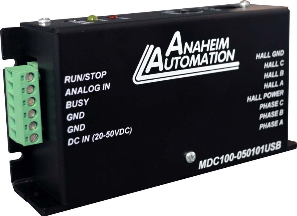
7 Terminal Descriptions Terminal Block 1. Position Description - Outputs to Motor 1 Phase A 2 Phase B 3 Phase C 4 HALL Power (5VDC) 5 HALL A 6 HALL B 7 HALL C 8 HALL GND Terminal Block 2. Position Description - Inputs 1 Run/Stop 2 Analog Input Voltage 3 Busy 4 GND 5 GND 6 DC Power Supply (20-50VDC) #L July 2018
8 Section 2: Functions Run At Given Set Point: This command causes the motor to start spinning at the set point speed. The set point value is in RPM. When the Set Point speed is too high for the motor or the controller to reach or if the load is too much for the motor to handle, the motor will run at the maximum speed possible. The motor will also run at the given set point with RUN/STOP input. Note: If the motor is started Digitally, it has to be stopped digitally. And if it is started with the RUN/STOP input, it has to be stopped through the RUN/STOP input. Hard Brake: This command causes the motor to come to an immediate stop. If the motor is moving fast, it will experience a jerk motion. Coast: This command causes the motor to stop with a constant deceleration and therefore motor will not experience a jerk-like motion. Go Clockwise: This command changes the direction of the motor to clockwise. Go Counter-clockwise: This command changes the direction of the motor to counterclockwise. Analog Input: One can start the motor in Analog mode via the BMC100 software of Analog Run/Stop Input. To set the speed Analog Voltage Input will read a voltage between 0 and +5VDC and based on the upper and lower limits of the function, a set point speed will be calculated for the motor to go to between the two limits. For example, if the lower limit is set to 0 RPM and the upper limit is set to 5000 RPM, and the analog input is set at +2.0VDC, then the motor will go to set point of 2000 RPM. Changing the lower limit to 1000 and the voltage to +3.2VDC, the motor will go to set point of 3560 RPM. See examples below for calculations of the analog inputs. (Upper-Lower) * (Voltage/5) = X Lower + X = Frequency Speed(rpm) = Lower Limit + ((Upper Limit - Lower Limit) * (Analog Voltage/5)) Example1: If Analog Voltage = 2V Speed = 0 + (5000-0) * (2 / 5) = 2000 RPM Example2: If Analog Voltage = 3.2V ( ) * (3.2 / 5) = = 3560 RPM RUN /Stop Input: Grounding this input will cause the motor to turn on in either Mode and making it High will stop the motor using either Coast or Hard Brake depending on which command was used last. If Coast was used last, it will Coast. Set Address: This command sets the address of the Controller. #L July 2018
9 Fetch Address: This command fetches the address of the Controller. Read Error: This command reads the error. These errors are explained in the error codes section on page number 22. PI Tuning The MDC USB implements an optimized PI controller to control the speed of a brushless motor. The following chart will help you find the optimum settings for your system. Parameter Increase Rise Time Overshoot Settling Time(Ts) Steady State Error (Ess) Ki (0-150) Kp (0-254) No Effect IV (0-1400) No Effect Explanation: Ki is the integrator constant for the closed loop PI controller. This is the most important constant for bringing the running RPM close to the Set Point RPM. Kp: If the difference between the running RPM and Set Point RPM is too great. the power applied to the motor is increased or decreased by the gain value before the PI controller takes over. IV (Initial Value): Initial value is the initial power applied to the motor by the controller. If the load requires higher torque, a higher initial value is required to start spinning the load. If the load on the motor is very small and if the Initial Value is really high, the motor may experience a jerk motion. #L July 2018
10 Section 3: BMC100 Software The BMC100 software is a handy utility that supports Anaheim Automation's MDC USB controller. The BMC100 uses a Serial Port and our proprietary Anaheim Automation protocol. This protocol is described in detail in the "Direct Talk Mode" Section. After connecting your PC to the MDC USB via a USB Cable, the BMC100 software can easily perform the following tasks: Exercise and monitor the MDC USB Controller Directly communicate with the MDC USB Controller Installation Software The BMC100 software is available for download online on our website menu under Download Software. The link to this web page is provided below: The BMC100 is compatible with all versions of Windows including Windows 8, Windows 7, Windows Vista, and Windows XP. Windows 8/7/XP/Vista Installation Getting Started Scroll down to BMC100 Program and Download the.zip file by clicking on the download link. Choose a download destination folder and download the file. 3. Extract the BMC100 folder. 4. Enter the folder and double click setup.exe file and follow the prompts to install the software. 1. Connect MDC USB to PC via USB. 2. Apply power to the MDC USB 3. Double click on the BMC100 icon to run the BMC100 Software. 4. Select MDC USB from the drop down menu and Click Select. 5. The Software will attempt to establish communications with the controller; if a connection is established, the BMC100 GUI will appear as seen in the picture on the following page. #L July 2018


11 6. If the software did not automatically establish a connection with the controller, the user can manually connect to it after making sure that the controller is powered on and connected to the PC via USB. In order to do this, click on the Setup menu and then Connect. The connect window will pop up as shown below. Select the appropriate COM port from the dropdown menu and click on Connect Controller. 7. Once the connection is made, all the other buttons will be enabled. Also, the default (if the controller is new) or previously programmed parameters will fill the given fields. #L July 2018
12 Motion Control Mode Direction Freewheel Brake Start Motor Stop Sets Analog or Digital Mode Set Clockwise or Counter Clockwise Direction Looking at Motor Shaft Let the Motor Coast to a Stop when a Stop Command is Received Immediately Stop the Motor when a Stop Command is Received Run The Motor at the Set Point Speed Immediately stops or lets the motor coast to a stop depending on the brake setting Motor Parameters Set Poles This Field Sets the Poles of the Motor Set Digital Set Point Sets the Set Point Running Speed in the Digital Mode Set Analog Min. Limit Sets the Lower Speed Limit for Analog Mode Set Analog Max. Limit Sets the Upper Speed Limit for Analog Mode Read All Update all the Parameters Factory Reset Set All the Parameters to the Factory Default These functions are explained in more details in the Functions Section. Controller Parameters Set Kp Sets the Proportional Constant Set Ki Sets the Integrator Constant Set Gain Sets the Gain Constant Set IV Sets the Initial Value Constant Read Error In Case of a Fault LED (Red) on the Board, Read Error *Warning: Ignore the FAULT LED followed by a Coast Command as this is a built in hardware feature that can not be replaced. In order to fine-tune the controller for your application, look at the PI Tuning Section. The Speed Parameters are constantly updated once the Motor is Started. In order to disconnect the controller, just click on the "Disconnect Controller" button. Warning: If the set point speed is too high for the motor to reach, the motor will run at the maximum speed possible. Two possible reasons this could happen are: 1. Higher than possible torque required for the specific load. 2. Given set point speed is more than the limit of the specific motor. #L July 2018
13 Section 4: Direct Talk Mode Direct mode is used to directly control motion for real time movements through serial communication. The MDC USB controller has 34 commands, which are easy to remember for direct control of a Brushless DC motor. COM Port Settings Baud Rate: Data Bits: 8 Parity: None Stop Bits: 1 Flow Control: Xon/Xoff NOTE: The unit communicates in half duplex mode, therefore proper setup of hyper terminal is necessary to view characters, if characters are to be echoed back to the screen. Unit Selection: In order to communicate with a unit, command followed by the address of the unit must be sent. NOTE: There should be no spaces between and address select. The factory default address of the unit is 0. How to select a (Unit 0 is (Unit 1 is (Unit 29 is selected) Instructions All instructions require that no spaces be sent between the command and the parameter followed by a carriage return. Carriage Return is ENTER on most Keyboards. Example: return) 0 (Command) (carriage return) #L July 2018
14 Command Summary Note: * dash (_) symbol represents the address of the unit. The range for the address is All the commands are explained in detail at the end of the list. Other dashes( ) represent a parameter. **The dash in the specific command (@# ) represents any of the 34 commands above. More detailed description of this command is in the command @# ** D - Digital Mode. Return) Description: Engage the Digital Mode. Example: If the unit is stopped and it is in analog will put it in digital mode. This command followed and makes the motor run at 2500 RPM. If the unit is running in Analog Mode, this command doesn't have any effect. A - Analog Mode. Return) Description: Engages the Analog Mode. Example: If the unit is stopped and in digital will put it in analog mode. This command followed or turning the Analog Brake Switch from OFF to ON makes the motor run at the speed calculated based on Analog Input Voltage and the respective analog min. #L July 2018
15 RPM and analog max. RPM. The input will read a voltage between 0 and +5VDC, and based on the upper and lower limits of the function, a max speed can be obtained based on a calculated frequency between the two points. See examples below for calculations of the analog inputs. Analog calculations. (Upper-Lower) * (Voltage/5) = X Lower + X = Frequency Example 1: If voltage is 2V and if Upper and Lower Limits are 5000 and 0 respectively. (5000-0) * (2 / 5) = = 2000 RPM Example 2: If voltage is 3.2V ( ) * (3.2 / 5) = = 3560 RPM + - Clockwise Direction Return) Description: Makes the motor spin clockwise. Example: When this command is sent to the controller, the direction of the motor becomes clockwise whether the motor is running or not. If the motor is already running in clockwise direction, there is no change. If it is running in counter clockwise when this command is entered, the motor makes a quick stop and starts running clockwise at the set point speed it was already running at. - - Counter - Clockwise Direction Return) Description: Makes the motor spin counter clockwise. Example: When this command is sent to the controller, the direction of the motor sets to counter clockwise whether the motor is running or not. If the motor is already running in counter clockwise direction, there is no change. If it is running in clockwise when this command is entered, the motor makes a quick stop and starts running counter clockwise at the set point speed it was already running at. #L July 2018
16 S - Start Motor Return) Description: Starts the motor in Analog as well as in Digital mode. Example: When this command is sent, the motor starts running at the set point speed based on other configurations. If the motor is started in analog mode, it can only be stopped and not the input switch. In other words, if the motor is started digitally, it can only be stopped digitally., - Coast (Carriage Return) Description: Coasts the motor to a stop if it is running in any mode. Example: When this command is transmitted, if the motor is running, it comes to a stop without any jerk motion. If the motor is not running, no effect is seen with this command. This command also makes the Analog Input Brake a Coast. Therefore after this command is applied, if the motor is restarted and is running in analog mode, and if the analog brake is applied, the motor will coast to a stop.. - Hard Brake (Carriage Return) Description: Engages Hard Brake if motor is running in any mode. Example: When this command is transmitted, if the motor is running, the controller performs a hard brake. When this brake is applied, the motor comes to an immediate stop. If the motor is running at high RPM this may cause the motor to jerk and move a little. This command also makes the Analog Input Brake a Hard brake. Therefore after this command is applied, if the motor is restarted and is running in analog mode, and after that if the analog brake is applied, the motor performs a hard brake as described. #L July 2018
17 M - Digital Set Point Speed Value)(Carriage Return) Description: Changes the set point speed of the digital mode to the speed represented by the dashes. It has no effect in Analog Mode. will set the Digital Mode speed to 2600 revolutions per minute. If the motor is running in digital mode at any speed, the motor will run at 2600 rpm after this command is issued. If the motor is stopped but restarted in digital mode after this command, the set point speed will run at 2600 RPM and the motor will go to 2600 RPM. Factory default is 2000 RPM. [ - Analog Speed Minimum Limit Value)(Carriage Return) Description: Changes the lower boundary of the Analog Mode speed represented by the RPM Value. changes the lower boundary of Analog Mode speed to 600 changes the lower boundary of Analog Mode speed to 1900 RPM. One condition for this is that the minimum speed has to be lower than or equal to the maximum speed. Therefore, if the maximum speed is assigned to 1800 will yield an error. If this error happens, no change is made to the minimum speed constant. This error is described in the Error Codes section. This boundary is used in calculating the set point speed for analog mode based on the formula described in the Calculating Analog Speed Section. Factory default is 1000 RPM. ] - Analog Speed Maximum Limit Value)(Carriage Return) Description: Changes the upper boundary of the Analog Mode speed represented by the RPM value. changes the upper boundary of the analog speed to 2000 changes the upper boundary of analog mode speed to 900 RPM. One condition for this is that the minimum speed has to be lower than or equal to the maximum speed. Therefore, if the minimum speed is assigned to 2000 will yield an error. If this error happens, no change is made to the maximum speed constant. This error is described in more details in the Error Codes section. This boundary is used in calculating the set point speed for analog mode based on the formula described in the Calculating Analog Speed Section. Factory default is 4000 RPM. #L July 2018
18 P - Set the Number of Poles of Poles of Motor)(Carriage Return) Description: Checks and stores the number of poles as represented by the Number of Poles of motor. Example: This information is crucial for correct RPM calculations. The default number of poles is 4. The options are 2,4,6,8,10,12. will set the poles parameter to 8. If the current poles parameter is set to will throw an error as described in the Error Codes section.! - Error Code Return) Description: Returns the error code as described in the Error Codes section. Example: If the analog max speed is lower than the analog min speed, this command will return 128. F - Factory Default Return) restores all the parameters and variables to default. These values are described in the Defaults on Start Up section. KG - Set Proportional Value Value)(Carriage Return) Description: Checks and stores the initial Proportional constant as represented by the Proportional Value. will make the Proportional constant 70. The range for KG is will return errors as described in the Error Codes Section. The default value is optimized for a 4 pole Brushless motor with small loads on them. The higher the load, the higher this value should be. #L July 2018
19 KP - Set Integrator Constant Value)(Carriage Return) Description: Checks and stores the Integrator constant as represented by the dashes. will make the Integrator constant 20. The range for KP is will return errors as described in the Error Codes Section. The default value is optimized for a 4 pole Brushless motor with small loads on them. The higher the load, the higher this value should be. IV - Initial Value Constant Constant Value)(Carriage Return) Description: Checks and stores the Initial Value constant as represented by the Proportional Constant Value. will make the Integrator constant 2. The range for this is will return errors as described in the Error Codes Section. The default value is optimized for a 4 pole Brushless motor with small loads on them. This value depends on the inertia of the load. As the inertia increases, a higher initial force is required to get the load spinning. For optimum results, this value should be increased as the load size or inertia is increased. VM - Return the Current RPM of the Motor. Return) Description: Returns the actual speed the motor is running at. Example: If motor is running at 1925 command will respond with 'M1925'. If motor is will respond with 'M0'. VS - Return the Current Set Point RPM of the Motor. Return) Description: Returns the actual set point speed of the motor. Example: It will return the calculated analog speed if it is in analog mode or the digital set speed if it is in digital mode. If the set point speed is 1630 will return 'S1630' #L July 2018
20 VN - Return the Lower Boundary of the Analog Mode Speed. Return) Description: Returns the lower boundary of the analog mode speed. Example: If the lower analog mode boundary is set to 1000 will return 'N1000' VX - Return the Upper Boundary of the Analog Mode Speed. Return) Description: Returns the upper boundary of the analog mode speed. Example: If the upper analog mode boundary is set to 3000 will return 'X3000' VDS - Return the Set Point Speed of the Digital Mode. Return) Description: Returns the Set Point Speed of the Digital Mode. Example: If the digital mode speed is set to 2500 will return 'DS2500'. It will do this in analog mode too but in analog mode, this won't be the actual current set point of the point of the motor. In analog mode, it will still return the digital mode speed.) VP - Return the User Set Number of Poles For the Motor. Return) Description: Returns the user set number of poles for the motor. Return). If the poles parameter is set to will return 'P6' VD - Return the Current Direction of the Motor. Return) Description: Returns the current direction of the motor. Example: If the direction is set to counter will return 'D-' or if the direction is clockwise, it will return 'D+.' '+' for clockwise, '-' would be for counter clockwise. #L July 2018
21 VMO - Returns the Mode. Return) Description: Returns the Mode of the controller. Example: Factory default is A for analog mode. If the mode is set to will return 'MOA.' If the mode is set to will return 'MOD' VST - Return Configuration of Stop Bit. Return) Description: Returns the current configuration for stop bit. Factory default is '.' for a hard stop. Example: If the stop bit parameter is set to will return 'ST,' and if the stop bit parameter is set to hard will return 'ST.'. VKG - Return the Gain Constant Return) returns the current Gain Constant for the motor. Factory default is 70. The range for KG is Example: If the Gain Value parameter is set to will return 'KG50'. VKP - Return the Proportional Constant Return) Description: Returns the current proportional constant for the motor. Factory default is 20. The range for Kp is Example: If the KP parameter is set to will return 'KP20.' VKI - Return the Integrator Constant Return) Description: Returns the current Integrator constant for the motor. Factory default is 1. The range for KI is 1-9. Example: If the KI parameter is set to will return 'KI1.' #L July 2018

22 VIV - Return the Initial Value Constant Return) Description: Returns the current Initial constant for the power applied to the motor. The factory default is 0. The range for this is The higher the inertia of the load, the higher this value should be. Example: If the IV parameter is set to will return 'IV150.' V* - Returns All the Values Mentioned Above. Return) Description: An example of this can be seen in the picture below: % - Fetches the Address of the Controller. Return) Description: Fetches the address of the controller. Example: If the address is Return) will return '0'. If the address is will return '29'. ~ - Sets the Address of the Unit. Value](Carriage Return) Description: Sets the address followed by "~." Range for the address is will set the address to will give an error as mentioned in the error codes section. #L July 2018
23 # - Match any Address Return) matches any address and executes the command that follows "#." Therefore, any command followed is executed no matter what the profile is. will start the will set the number of poles to 6. #L July 2018
24 Troubleshooting Problem: Cannot establish communications with the MDC USB. Possible Solutions: 1) Make sure the MDC USB controller has power. Is the Green LED on? 2) Check the USB connections. 3) Check for loose cable connections on the MDC USB 4) Was the software installed successfully? 5) Go to Setup Com Port Settings and verify COM port and baudrate settings. 6) If problems still exist, contact Anaheim Automation Tech Support. Anaheim Automation, Inc. Tech Support: 4985 E. Landon Drive Anaheim, CA, phone: (714) fax: (714) Problem: There is no power to the MDC USB controller. Possible Solutions: 1) Is the MDC USB controller connected to the appropriate power supply? 2) Check for any blown fuses in line with the MDC USB controller. 3) If problems still exist, contact Anaheim Automation, Inc. Tech Support. Error Codes 1 BCMND ERR,0 ;Invalid command 2 BRANGE ERR,1 ;Invalid # of characters for the command 4 BTIME ERR,2 ;While motor is running, certain instructions can't be performed 8 BPOLES ERR,3 ;Poles have to be even numbers in 2-12 range 16 BPRANGE ERR,4 ;Bad Integral range. Range is BGRANGE ERR,6 ;Bad Proportional range. Range is BRPMRANGE ERR,7 ;RPM min> RPM max and RPM min< BIVRANGE ERR2,0 ;Initial Value range is Examples of each error codes: If the Address is not correct for the controller, it will not display any error as it will not be just ignoring the command. If any of the following errors occur, no command is executed. All the following examples assume that the address of the controller is 0. These examples trigger the given ERROR CODE. #L July 2018
25 1. Invalid 2. Invalid # of characters for the specified command. Too many characters in 4. While motor is running, following instructions can't be performed. They are all checked for. These will be triggered only if the motor If any of these also had too many characters, it will actually return error code Poles have to be even numbers in 16. Bad Integrator Constant (Kp) range. Range gives ERROR code Bad Proportional range. Range @0KG999. gives ERROR code Analog RPM min > Analog RPM max will give ERROR code 128. If Analog max is set at will give this error. gives ERROR code 2 If Analog min is set at will give this error. gives ERROR code Bad initial value Range. Initial Value range will give ERROR code 2. #L July 2018
26 Appendix 1: ASCII Table for Direct Mode ASCII Symbol Hex Value ASCII Symbol Hex Value ASCII Symbol Hex Value 0 30 J 4A # K 4B $ L 4C % M 4D " N 4E ( O 4F + 2B 6 36 P 50, 2C 7 37 Q 51-2D 8 38 R 52. 2E 9 39 S 53 : 3A A 41 T 54 ; 3B B 42 U 40 C 43 V 56 [ 5B D 44 W 57 ] 5D E 45 X 58 ^ 5E F 46 Y 59 { 7B G 47 Z 5A } 7D H 48 Carriage Return 0D ~ 7E I 49! 21 #L July 2018
27 Copyright Copyright 2014 by Anaheim Automation, Inc.. All rights reserved. No part of this publication may be reproduced, transmitted, transcribed, stored in a retrieval system, or translated into any language, in any form or by any means, electronic, mechanical, magnetic, optical, chemical, manual, or otherwise, without the prior written permission of Anaheim Automation, Inc., 4985 E. Landon Drive, Anaheim, CA, The only exception to this would be use of the program examples in this manual. Disclaimer Though every effort has been made to supply complete and accurate information in this manual, the contents are subject to change without notice or obligation to inform the buyer. In no event will Anaheim Automation, Inc. be liable for direct, indirect, special, incidental, or consequential damages arising out of the use or inability to use the product or documentation. Limited Warranty All Anaheim Automation, Inc. products are warranted against defects in workmanship, materials and construction, when used under Normal Operating Conditions and when used in accordance with specifications. This warranty shall be in effect for a period of twelve months from the date of purchase or eighteen months from the date of manufacture, whichever comes first. Warranty provisions may be voided if the products are subjected to physical damage or abuse. Anaheim Automation, Inc. will repair or replace at its option, any of its products which have been found to be defective and are within the warranty period, provided that the item is shipped freight prepaid, with RMA (return material authorization), to Anaheim Automation s plant in Anaheim, California. Trademarks Control Link and Driver Pack are registered trademarks of Anaheim Automation, Inc. IBM PC is a registered trademark of International Business Machines, Inc. #L July 2018
MDC V, 2A Brushless Controller. User s Guide E. Landon Drive Anaheim, CA
 MDC010-024031 24V, 2A Brushless Controller User s Guide A N A H E I M A U T O M A T I O N 4985 E. Landon Drive Anaheim, CA 92807 e-mail: info@anaheimautomation.com (714) 992-6990 fax: (714) 992-0471 website:
MDC VAC Input Brushless Controller. User s Guide. 910 East Orangefair Lane, Anaheim, CA
 MDC200-048051 110VAC Input Brushless Controller User s Guide A N A H E I M A U T O M A T I O N 910 East Orangefair Lane, Anaheim, CA 92801 e-mail: info@anaheimautomation.com (714) 992-6990 fax: (714) 992-0471
MBC Bipolar Microstep Driver. User s Guide E. Landon Drive Anaheim, CA
 MBC10641 Bipolar Microstep Driver User s Guide A N A H E I M A U T O M A T I O N 4985 E. Landon Drive Anaheim, CA 92807 e-mail: info@anaheimautomation.com (714) 992-6990 fax: (714) 992-0471 website: www.anaheimautomation.com
MBC Bipolar Microstep Driver. User s Guide. 910 East Orangefair Lane, Anaheim, CA
 MBC032561 Bipolar Microstep Driver User s Guide A N A H E I M A U T O M A T I O N 910 East Orangefair Lane, Anaheim, CA 92801 e-mail: info@anaheimautomation.com (714) 992-6990 fax: (714) 992-0471 website:
MBC10P31 Series. Programmable Pulse Generator. User s Guide. 910 East Orangefair Lane, Anaheim, CA
 MBC10P31 Series Programmable Pulse Generator User s Guide A N A H E I M A U T O M A T I O N 910 East Orangefair Lane, Anaheim, CA 92801 e-mail: info@anaheimautomation.com (714) 992-6990 fax: (714) 992-0471
BLD75-1. Bilevel Step Motor Driver. User s Guide. #L010125
 BLD75-1 Bilevel Step Motor Driver User s Guide A N A H E I M A U T O M A T I O N #L010125 1 Features Unipolar Operation 10 Amps per Phase Operating Current (Kick Current) 7 Amps per Phase Standstill Current
MLA High Performance Microstepping Driver. User s Guide E. Landon Drive Anaheim, CA
 MLA10641 High Performance Microstepping Driver User s Guide A N A H E I M A U T O M A T I O N 4985 E. Landon Drive Anaheim, CA 92807 e-mail: info@anaheimautomation.com (714) 992-6990 fax: (714) 992-0471
Tarocco Closed Loop Motor Controller
 Contents Safety Information... 3 Overview... 4 Features... 4 SoC for Closed Loop Control... 4 Gate Driver... 5 MOSFETs in H Bridge Configuration... 5 Device Characteristics... 6 Installation... 7 Motor
SRVODRV REV7 INSTALLATION NOTES
 SRVODRV-8020 -REV7 INSTALLATION NOTES Thank you for purchasing the SRVODRV -8020 drive. The SRVODRV -8020 DC servo drive is warranted to be free of manufacturing defects for 1 year from the date of purchase.
K-Factor Scaler F5140 and Programming Kit F5141 Installation & Operating Instructions
 F5140 and Programming Kit F5141 8635 Washington Avenue Racine, WI 53406 USA Tel: 800-433-5263 or 262-639-6770 Fax: 800-245-3569 or 262-639-2267 E-Mail: flo-techsales@racinefed.com www.flo-tech.com TABLE
Installation Tech Note Dallas, Texas
 AMC B40A40AC Installation Tech Note Dallas, Texas May, 2010 ! CAUTION! Do NOT apply air pressure to release the collet while the servo motor is rotating. The servo motor spindle must be FULLY STOPPED before
Fiber Optic Expansion Interface
 User Manual for the HE697FBX100 & HE697FBX105 Fiber Optic Expansion Interface Fourth Edition 20 November 1998 MAN0215-04 PREFACE 20 NOV 1998 PAGE 2 PREFACE This manual explains how to use the Fiber Optic
Pololu Jrk USB Motor Controller
 Pololu Jrk USB Motor Controller User's Guide 1. Overview.................................................... 2 1.a. Module Pinout and Components.................................... 4 1.b. Supported Operating
Using CME 2 with AccelNet
 Using CME 2 with AccelNet Software Installation Quick Copy (with Amplifier file) Quick Setup (with motor data) Offline Virtual Amplifier (with no amplifier connected) Screen Guide Page 1 Table of Contents
DSB810A Digital DC Servo Driver Manual V1.0
 User s Manual For DSB810A Digital DC Servo Driver Version 1.0 2007 All Rights Reserved Attention: Please read this manual carefully before using the driver! The content in this manual has been carefully
GM8036 Laser Sweep Optical Spectrum Analyzer. Programming Guide
 GM8036 Laser Sweep Optical Spectrum Analyzer Programming Guide Notices This document contains UC INSTRUMENTS CORP. proprietary information that is protected by copyright. All rights are reserved. This
Programmable K-Factor Scaler B and Programming Software Kit B
 Programmable K-Factor Scaler B220-885 and Programming Software Kit B220-900 INSTALLATION & INSTRUCTION MANUAL 8635 Washington Avenue Racine, Wisconsin 53406 Toll Free: 800.235.1638 Phone: 262.639.6770
USER GUIDE. Piezo Motor with Encoder. Installation & Software Control Guide. (For Piezo Motor Model LPM-2M, LPM-5, PM-1124R)
") www.dtimotors.com USER GUIDE Piezo Motor with Encoder Installation & Software Control Guide (For Piezo Motor Model LPM-2M, LPM-5, PM-1124R) Version 05312018v11 Page 0 Table of Contents 1.0 Introduction...
www.dtimotors.com USER GUIDE Piezo Motor with Encoder Installation & Software Control Guide (For Piezo Motor Model LPM-2M, LPM-5, PM-1124R) Version 05312018v11 Page 0 Table of Contents 1.0 Introduction...
40 Amp Digital Bidirectional PWM Motor Controller with Regenerative Braking BIDIR-340-DR
 40 Amp Digital Bidirectional PWM Motor Controller with Regenerative Braking BIDIR-340-DR The BIDIR-340-DR is a fully solid-state motor controller that allows you to control the speed and direction of a
STEPPING MOTOR EMULATION
 OPERATING MANUAL SERIES SMTBD1 OPTIONAL FUNCTIONS (Version 2.0) European version 2.0 STEPPING MOTOR EMULATION OPTION C This manual describes the option "C" of the SMT-BD1 amplifier: Stepping motor emulation.
LCC-10 Product manual
 LCC-10 Product manual Rev 1.0 Jan 2011 LCC-10 Product manual Copyright and trademarks Copyright 2010 INGENIA-CAT, S.L. / SMAC Corporation Scope This document applies to i116 motion controller in its hardware
Harris IRT Enterprises Multi-Channel Digital Resistance Tester Model XR
 Harris IRT Enterprises Multi-Channel Digital Resistance Tester Model 6012-06XR Specifications & Dimensions 2 Theory of Operation 3 System Block Diagram 4 Operator Controls & Connectors 5 Test Connections
G320X MANUAL DC BRUSH SERVO MOTOR DRIVE
 G320X MANUAL DC BRUSH SERVO MOTOR DRIVE Thank you for purchasing the G320X drive. The G320X DC servo drive is warranted to be free of manufacturing defects for 3 years from the date of purchase. Any customer
OVEN INDUSTRIES, INC. Model 5C7-362
 OVEN INDUSTRIES, INC. OPERATING MANUAL Model 5C7-362 THERMOELECTRIC MODULE TEMPERATURE CONTROLLER TABLE OF CONTENTS Features... 1 Description... 2 Block Diagram... 3 RS232 Communications Connections...
BLuAC5 Brushless Universal Servo Amplifier
 BLuAC5 Brushless Universal Servo Amplifier Description The BLu Series servo drives provide compact, reliable solutions for a wide range of motion applications in a variety of industries. BLu Series drives
SSI-4 PLUS User Manual
 SSI-4 PLUS User Manual 1 SSI-4 PLUS... 2 1.1 Getting to Know the SSI-4 PLUS... 2 1.2 Channel Functions... 3 2 Wiring and Setup... 3 2.1 Powering the SSI-4 PLUS... 3 2.2 5V for External Sensors... 4 2.3
Speed Feedback and Current Control in PWM DC Motor Drives
 Exercise 3 Speed Feedback and Current Control in PWM DC Motor Drives EXERCISE OBJECTIVE When you have completed this exercise, you will know how to improve the regulation of speed in PWM dc motor drives.
UNICOM 2500 UNICOM Installation Operation Programming. Universal Communication Converter
 User Manual UNICOM 2500 Installation Operation Programming Universal Communication Converter UNICOM 2500 Electro Industries/GaugeTech 1800 Shames Drive Westbury, New York 11590 Tel 516.334.0870 Fax 516.338.4741
Instruction Manual ABM HART Gateway Software. Instruction Manual Revision A.1
 Instruction Manual ABM HART Gateway Software Instruction Manual Revision A.1 Table of Contents Section 1: Getting Started... 3 1.1 Setup Procedure... 3 1.2 Quick Setup Guide for Ultrasonic Sensors... 11
Servo Indexer Reference Guide
 Servo Indexer Reference Guide Generation 2 - Released 1/08 Table of Contents General Description...... 3 Installation...... 4 Getting Started (Quick Start)....... 5 Jog Functions..... 8 Home Utilities......
AMERITRON RCS-12 AUTOMATIC ANTENNA SWITCH
 AMERITRON RCS-12 AUTOMATIC ANTENNA SWITCH INSTRUCTION MANUAL PLEASE READ THIS MANUAL BEFORE OPERATING THIS EQUIPMENT! 116 Willow Road Starkville, MS 39759 USA 662-323-8211 Version 3B Printed in U.S.A.
Ocean Controls KT-5221 Modbus IO Module
 Ocean Controls Modbus IO Module 8 Relay Outputs 4 Opto-Isolated Inputs 2 Analog Inputs (10 bit) 1 PWM Output (10 bit) 4 Input Counters Connections via Pluggable Screw Terminals 0-5V or 0-20mA Analog Inputs,
Software User Manual
 Software User Manual ElectroCraft CompletePower Plus Universal Servo Drive ElectroCraft Document Number: 198-0000021 2 Marin Way, Suite 3 Stratham, NH 03885-2578 www.electrocraft.com ElectroCraft 2018
maxon document number:
 maxon document number: 791272-04 1 Table of contents... 2 2 Table of figures... 3 3 Introduction... 4 4 How to use this guide... 4 5 Safety Instructions... 5 6 Performance Data... 6 6.1 Motor data... 6
ADVANCED MICRO CONTROLS INC. Manual #: 940-0D043
 ADVANCED MICRO CONTROLS INC. Manual #: 940-0D043 User Manual GENERAL INFORMATION Important User Information The products and application data described in this manual are useful in a wide variety of different
Lab 5: Inverted Pendulum PID Control
 Lab 5: Inverted Pendulum PID Control In this lab we will be learning about PID (Proportional Integral Derivative) control and using it to keep an inverted pendulum system upright. We chose an inverted
CCE Image may differ from the actual product By Martin Labbé, eng., Jasmin Goupil & Louis Perreault
 CCE-32 1.09 Image may differ from the actual product By Martin Labbé, eng., Jasmin Goupil & Louis Perreault Index 1. General description... 5 2. Applications... 5 3. Installation... 5 4. Connections...
EVDP610 IXDP610 Digital PWM Controller IC Evaluation Board
 IXDP610 Digital PWM Controller IC Evaluation Board General Description The IXDP610 Digital Pulse Width Modulator (DPWM) is a programmable CMOS LSI device, which accepts digital pulse width data from a
Everything will be securely inserted inside the box so items do not shift during shipping and handling. Rev D 2
 Installation Guide Shipping Box Contains Everything that is included in the box being shipped to should contain the following items: Receiver Assembly Documentation on CD ROM Tags, if placed in the same
RAZER RAIJU TOURNAMENT EDITION
 RAZER RAIJU TOURNAMENT EDITION MASTER GUIDE The Razer Raiju Tournament Edition is the first Bluetooth and wired controller to have a mobile configuration app, enabling control from remapping multi-function
EE 314 Spring 2003 Microprocessor Systems
 EE 314 Spring 2003 Microprocessor Systems Laboratory Project #9 Closed Loop Control Overview and Introduction This project will bring together several pieces of software and draw on knowledge gained in
FlatPack Ultrasonic Sensors
 FlatPack Ultrasonic Sensors Installation & Operation Guide May 23, 2017 The FlatPack Sensor product line listed in the introduction of this manual complies with the European Council EMC Directive 2004/108/EC
LVTX-10 Series Ultrasonic Sensor Installation and Operation Guide
 LVTX-10 Series Ultrasonic Sensor Installation and Operation Guide M-5578/0516 M-5578/0516 Section TABLE OF CONTENTS 1 Introduction... 1 2 Quick Guide on Getting Started... 2 Mounting the LVTX-10 Series
BLuAC5 Brushless Universal Servo Amplifier
 BLuAC5 Brushless Universal Servo Amplifier Description The BLu Series servo drives provide compact, reliable solutions for a wide range of motion applications in a variety of industries. BLu Series drives
4590 Tank Side Monitor. Service Manual. Mark/Space Communication Protocol. Software Version v2.03 SRM009FVAE0808
 SRM009FVAE0808 4590 Tank Side Monitor Mark/Space Communication Protocol Service Manual Software Version v2.03 www.varec.com Varec, Inc. 5834 Peachtree Corners East, Norcross (Atlanta), GA 30092 USA Tel:
Manual Intelligent Motion Controller
 Manual Intelligent Motion Controller IMC5510 An ERIKS brand e ERIKS bv Aandrijftechniek Schoonhoven ERIKS bv Broeikweg 25 2871 RM Schoonhoven The Netherlands info.schoonhoven@eriks.nl www.elmeq.nl Tel:
Model 12PR1A. User Manual
 12 Volt Ultra-Portable Antenna Rotor System Single Axis Model 12PR1A User Manual Document Rev 1.1 Copyright 2013-14 Portable Rotation Patent Pending Page 1 Warranty All products sold by Portable Rotation
LD2342 USWM V1.6. LD2342 V1.4 Page 1 of 18
 LD2342 USWM V1.6 LD2342 V1.4 Page 1 of 18 GENERAL WARNINGS All Class A and Class B marine Automatic Identification System (AIS) units utilize a satellite based system such as the Global Positioning Satellite
MFJ ENTERPRISES, INC.
 Radio Interface Model MFJ-5124K/Y INSTRUCTION MANUAL CAUTION: Read All Instructions Before Operating Equipment! MFJ ENTERPRISES, INC. 300 Industrial Park Road Starkville, MS 39759 USA Tel: 662-323-5869
MADEinUSA OPERATOR S MANUAL. RS232 Interface Rev. A
 MADEinUSA OPERATOR S MANUAL RS232 Interface 92-3006 Rev. A www.iradion.com Iradion Laser, Inc. 51 Industrial Dr. N. Smithfield, RI 02896 (410) 762-5100 Table of Contents 1. Overview... 2 2. Equipment Required...
EXECUTE Shiloh Road Alpharetta, Georgia (770) FAX (770) Toll Free
 FAX (770) Toll Free") Instruction Manual Model 1586-06 RF Attenuator May 2009 Rev A 1 2 3 12.5 53.5 16.3 MODEL 1586 RF ATTENUATOR CROSS TECHNOLOGIES INC. EXECUTE PS1 PS2 Data, drawings, and other material contained herein are
Instruction Manual Model 1586-06 RF Attenuator May 2009 Rev A 1 2 3 12.5 53.5 16.3 MODEL 1586 RF ATTENUATOR CROSS TECHNOLOGIES INC. EXECUTE PS1 PS2 Data, drawings, and other material contained herein are
AUTOMATION. Operator s Manual. IRU-2xx4/3xx4 Series. Rev. A2, 11/08 Doc
 AUTOMATION P R O D U C T S G R O U P, I N C. Operator s Manual IRU-2xx4/3xx4 Series Rev. A2, 11/08 Doc. 9002673 Tel: 1/888/525-7300 Fax: 1/435/753-7490 www.apgsensors.com E-mail: sales@apgsensors.com IRU-2xx4/3xx4
Instruction Manual MT-945SL Four Channel Video Transmitter With Two Bi-Directional Data Channels
 Instruction Manual MT-945SL Four Channel Video Transmitter With Two Bi-Directional Data Channels Copyright 2006, American Fibertek, Inc. 0307JD Table of Contents Functional Description... 3 Installation...
Instruction Manual MX-485-S Bi-directional RS485 Data Transceiver
 Instruction Manual MX-485-S Bi-directional RS485 Data Transceiver Copyright 2005, American Fibertek, Inc. 1020JD Table of Contents Functional Description...3 Installation...3 Power Source...3 Power Connection...3
HPVFP High Performance Full Function Vector Frequency Inverter
 Advanced User Manual HPVFP High Performance Full Function Vector Frequency Inverter HP VER 1.00 1. HPVFP Parameter Set Overview...3 1.1. About this section...3 1.2. Parameter Structure Overview...3 1.3.
RF Wireless Serial Device Server
 RF-SDS RF Wireless Serial Device Server The RF-SDS subassembly is a radio transceiver acting as a Serial Device Server, which externally connects a remote serial RF transceiver to an Ethernet network (TCP/IP).
Independent Technology Service Inc Independence Ave. Chatsworth, California Toll Free:
 Independent Technology Service Inc. 9182 Independence Ave. Chatsworth, California 91311 www.itscnc.com Toll Free: 1.800.342.3475 NEW Brush Amplifiers For Fadal Machines AMP-0006N-ITS AMP-0021N-ITS NEW
User Manual. Last updated on September 5, 2008
 User Manual AlfaSpid by Hy-Gain For use with: AlfaSpid Rotator RAS1 & Controller Rot2Prog by Hy-Gain Azimuth and Elevation rotator and controller AZ/EL RAS1 OR Elevation rotator and controller EL REAL1
HILINK REAL-TIME HARDWARE-IN-THE-LOOP CONTROL PLATFORM FOR MATLAB/SIMULINK
 REAL-TIME HARDWARE-IN-THE-LOOP CONTROL PLATFORM FOR MATLAB/SIMULINK Quick Reference release 1.7 May 1, 2016 Disclaimer The developers of the platform (hardware and software) have used their best efforts
Gentec-EO USA. T-RAD-USB Users Manual. T-Rad-USB Operating Instructions /15/2010 Page 1 of 24
 Gentec-EO USA T-RAD-USB Users Manual Gentec-EO USA 5825 Jean Road Center Lake Oswego, Oregon, 97035 503-697-1870 voice 503-697-0633 fax 121-201795 11/15/2010 Page 1 of 24 System Overview Welcome to the
Endurance R/C Wi-Fi Servo Controller 2 Instructions
 Endurance R/C Wi-Fi Servo Controller 2 Instructions The Endurance R/C Wi-Fi Servo Controller 2 allows you to control up to eight hobby servos, R/C relays, light controllers and more, across the internet
M-300 & M-320 Low Cost Ultrasonic Sensors
 M-300 & M-320 Family of Low Cost Ultrasonic Sensors December 23, 2014 Copyright 2014 by Massa Products Corporation. All rights reserved. Section TABLE OF CONTENTS Page 1 Introduction... 1 2 Quick Guide
An American Control Electronics Brand PCM4 SERIES USER MANUAL PCM4.
 An American Control Electronics Brand PCM4 SERIES PCM4 USER MANUAL www.minarikdrives.com Dear Valued Consumer: Congratulations on your purchase of the PCM4 Series isolation card. This User Manual was created
ies-2309 Integrated Easy Servo
 Datasheet of the integrated easy servo motor ies-09 ies-09 Integrated Easy Servo Motor + Drive + Encoder, 0-0VDC, NEMA, 0.9Nm Features Easy servo control technology to combine advantages of open-loop stepper
EchoSonic II Ultrasonic Level Transmitter LU27 Series Quick Start NEMA 4X Enclosure
 EchoSonic II Ultrasonic Level Transmitter LU27 Series Quick Start NEMA 4X Enclosure QS300116 Rev C 2013 Flowline, Inc. All Rights Reserved Made in USA 10500 Humbolt Street, Los Alamitos, CA 90720 USA Tel:
TEK-TROL HART GATEWAY SOFTWARE. Operating Instruction Manual.
 TEK-TROL HART GATEWAY SOFTWARE Operating Instruction Manual www.tek-trol.com Table of Contents 1 Getting Started... 2 1.1 Setup Procedure... 2 1.2 Quick Setup Guide for Radar Sensors... 10 2 Level device
Integrated Easy Servo
 ies 1706 Integrated Easy Servo Motor + Drive + Encoder, 18 32VDC, NEMA17, 0.6Nm Features Easy servo control technology to combine advantages of open loop stepper systems and brushless servo systems Closed
EchoSonic II Ultrasonic Level Transmitter LU23, LU28 & LU29 Series Quick Start NEMA 4X Enclosure
 EchoSonic II Ultrasonic Level Transmitter LU23, LU28 & LU29 Series Quick Start NEMA 4X Enclosure QS300480 Rev B 2013 Flowline, Inc. All Rights Reserved Made in USA 10500 Humbolt Street, Los Alamitos, CA
TMC603EVAL MANUAL Evaluation board for the TMC603 three phase motor driver with BLDC back EMF commutation hallfx
 TMC603EVAL MANUAL Evaluation board for the TMC603 three phase motor driver with BLDC back EMF commutation hallfx TRINAMIC Motion Control GmbH & Co. KG Sternstraße 67 D 20357 Hamburg GERMANY www.trinamic.com
Instruction Manual MX-480 Bi-directional Multi-Protocol Data
 Instruction Manual MX-480 Bi-directional Multi-Protocol Data Copyright 2007, American Fibertek, Inc. 1210JD Table of Contents Functional Description...3 Installation...3 Power Source...3 Power Connection...4
LC-10 Chipless TagReader v 2.0 August 2006
 LC-10 Chipless TagReader v 2.0 August 2006 The LC-10 is a portable instrument that connects to the USB port of any computer. The LC-10 operates in the frequency range of 1-50 MHz, and is designed to detect
MTY (81)
") This manual describes the option "d" of the SMT-BD1 amplifier: Master/slave electronic gearing. The general information about the digital amplifier commissioning are described in the standard SMT-BD1 manual.
This manual describes the option "d" of the SMT-BD1 amplifier: Master/slave electronic gearing. The general information about the digital amplifier commissioning are described in the standard SMT-BD1 manual.
CME 2 User Guide P/N CC Revision A June 2009
 CME 2 User Guide P/N CC95-00454-000 Revision A June 2009 CME 2 User Guide TABLE OF CONTENTS About This Manual... 5 1: Introduction... 7 1.1: Host Computer Requirements... 8 1.2: Amplifier Commissioning
EDE1204 Bi-Polar Stepper Motor IC
 EDE1204 Bi-Polar Stepper Motor IC EDE1204 Coil B Control Signal 1 Coil B Coil A 18 Coil A Control Signal Coil B Control Signal 2 Coil B Coil A 17 Coil A Control Signal Connect to +5V DC 3 +5V OSC1 16 Oscillator
10 Error Code List. Motion Control SW. NTI AG / LinMot User Manual Motion Control SW/ Page 87/94
 Motion Control SW L i n M o t 10 List Code Description Actions to take 0000h No Error No error is pending. 0001h X4 Logic Supply Too Low The logic supply voltage has been too low. The minimal logic supply
POWER SERIES Plus. Volt / Amp / Hertz. Digital Switchboard Meter. User s Manual IM2493VAF-3
 POWER SERIES Plus Volt / Amp / Hertz Digital Switchboard Meter User s Manual General Description The POWER SERIES Plus digital switchboard meters incorporate the latest DSP microprocessor technology. Careful
af i Instruction Manual MR-944C Four Channel Video Receiver With One Bi-Directional Multi-Protocol Data Channel american fibertek 11/30/2012 JPK
 af i american fibertek Instruction Manual MR-944C Four Channel Video Receiver With One Bi-Directional Multi-Protocol Data Channel 11/30/2012 JPK Table of Contents Functional Description... 3 Installation...
DXXX Series Servo Programming...9 Introduction...9 Connections HSB-9XXX Series Servo Programming...19 Introduction...19 Connections...
 DPC-11 Operation Manual Table of Contents Section 1 Introduction...2 Section 2 Installation...4 Software Installation...4 Driver Installastion...7 Section 3 Operation...9 D Series Servo Programming...9
Job Sheet 2 Servo Control
 Job Sheet 2 Servo Control Electrical actuators are replacing hydraulic actuators in many industrial applications. Electric servomotors and linear actuators can perform many of the same physical displacement
Variable Speed Brushed DC Motor Drive
 The driving force of motor control & electronics cooling. Equinox: Variable Speed Brushed DC Motor Drive Navigator Equinox The Equinox variable speed brushed DC motor drive with Navigator Programmer is
TOSHIBA MACHINE CO., LTD.
 User s Manual Product SHAN5 Version 1.12 (V Series Servo Amplifier PC Tool) Model SFV02 July2005 TOSHIBA MACHINE CO., LTD. Introduction This document describes the operation and installation methods of
Blue Bamboo P25 Device Manager Guide
 Blue Bamboo P25 Device Manager Guide Version of Device Manager: 1.1.28 Document version: 2.3 Document date: 2011-09-20 Products: P25 / P25-M / P25i / P25i-M BLUE BAMBOO Headquarters Blue Bamboo Transaction
User Manual Solenoid Controller BI-SC1001
 User Manual Solenoid Controller BI-SC1001 NOTICE Brandstrom Instruments, 2017 85 Ethan Allen Highway Ridgefield, CT 06877 (203) 544-9341 www.brandstrominstruments.com No part of this document may be photocopied,
WBT900. User s Manual. 900 MHz Wireless BACnet MSTP Radio. Page 1
 WBT900 User s Manual 900 MHz Wireless BACnet MSTP Radio www.aic-wireless.com Page 1 Thank you for your purchase of the WBT900, Wireless BACnet MSTP Transceiver. With appropriate placement and antenna selection,
Ultimate Actuator Drivebox 30A Quick start guide
 2016 Ultimate Actuator Drivebox 30A Quick start guide info@e-tronix.cz e-tronix s.r.o. 1.1.2016 OBSAH Identification... 3 Serial Number... 3 Manufacturer and reseller contact... 4 Before Start... 4 UAD30A
Product Manual. 232-Amp+ 232-Amp+W. RS-232 Stereo Mixer/Amplifier Ver 2.3 July 19, 2016
 Product Manual 232-Amp+ 232-Amp+W RS-232 Stereo Mixer/Amplifier Ver 2.3 July 19, 2016 Table of Contents Overview... 3 Specifications... 4 Field Setup... 5 Mix/Ducking Operation... 5 RS-232 Control Protocol...
Software Operational Manual
 Software Operational Manual for Easy Servo Drives ES-D508/808/1008 www.leadshine.com SM-ES-R20121030 ii Leadshine reserves the right to make changes without further notice to any products herein to improve
15 Amp Digital High Frequency PWM Motor Speed Controller SPD-315-D and SPD-315-DS
 15 Amp Digital High Frequency PWM Motor Speed Controller SPD-315-D and SPD-315-DS The SPD-315-D(S) PWM controller allows you to control the speed of a motor, brightness of a lamp or other load using a
SL300 Snow Depth Sensor USL300 SNOW DEPTH SENSOR. Revision User Manual
 USL300 SNOW DEPTH SENSOR Revision 1.1.2 User Manual 1 Table of Contents 1. Introduction... 3 2. Operation... 3 2.1. Electrostatic Transducer... 4 2.2. SL300 Analog Board... 4 2.3. SL300 Digital Circuit
PI-10 Broadband Power Indicator
 PI-10 Broadband Power Indicator HIGH RF VOLTAGES MAY BE PRESENT AT THE PORTS OF THIS UNIT. All operating personnel should use extreme caution in handling these voltages and be thoroughly familiar with
TECHNICAL DATASHEET #TDAX QUAD VALVE CONTROLLER P/N: AX SERIES
 TECHNICAL DATASHEET #TDAX020500 QUAD VALVE CONTROLLER P/N: AX020500 SERIES Multiple Digital, Analog or PWM Command Inputs 4 Independent Proportional Outputs and 1 On/Off Output Standard Open Loop Control
HURRICANE Radio Modem. FULL DUPLEX Radio MODEM
 FULL DUPLEX Radio MODEM Direct Cable Replacement Range 2KM RS232 / RS485 / USB Host Data Rates up to 38,400 Baud RF Data Rates to 115200Kbps Waterproof IP68 Enclosure 8 User Selectable Channels CE Compliant
USER MANUAL MODEL Parallel to Serial/ Serial to Parallel Interface Converter
 USER MANUAL MODEL 2029 Parallel to Serial/ Serial to Parallel Interface Converter C E R T I F I E D An ISO-9001 Certified Company Part #07M2029-B, Rev. C Doc. #102011UB Revised 6/16/09 SALES OFFICE (301)
AN-SERV-009. Luis Miranda 1
 THIS INFORMATION PROVIDED BY AUTOMATIONDIRECT.COM TECHNICAL SUPPORT IS SUPPLIED "AS IS", WITHOUT ANY GUARANTEE OF ANY KIND. These documents are provided by our technical support department to assist others.
CHAPTER AC DRIVE PARAMETERS. In This Chapter...
 CHAPTER AC DRIVE 4 PARAMETERS In This Chapter... GS2 Parameter Summary....................4 2 Detailed Parameter Listings.................4 11 Motor Parameters........................4 11 Ramp Parameters.........................4
M F TYPE S R-SETUP. Setup Software
 M0006935F TYPE S R-SETUP Setup Software Preface This user s manual explains the use and specifications of the Setup Software for AC servo amplifier R series. Notifications on this User s Manual: To completely
PI-150 Broadband Power Indicator
 PI-150 Broadband Power Indicator HIGH RF VOLTAGES MAY BE PRESENT AT THE PORTS OF THIS UNIT. All operating personnel should use extreme caution in handling these voltages and be thoroughly familiar with
CDT. Service and Installation Manual. Manual Revision Oct 2014
 CDT Service and Installation Manual Manual Revision Oct 2014 2014 Cimarron Technologies Corp., Escondido, CA, USA. All rights reserved. No part of this manual may be reproduced in any way without the express
HB-25 Motor Controller (#29144)
") Web Site: www.parallax.com Forums: forums.parallax.com Sales: sales@parallax.com Technical: support@parallax.com Office: (916) 624-8333 Fax: (916) 624-8003 Sales: (888) 512-1024 Tech Support: (888) 997-8267
Web Site: www.parallax.com Forums: forums.parallax.com Sales: sales@parallax.com Technical: support@parallax.com Office: (916) 624-8333 Fax: (916) 624-8003 Sales: (888) 512-1024 Tech Support: (888) 997-8267
EE-110 Introduction to Engineering & Laboratory Experience Saeid Rahimi, Ph.D. Labs Introduction to Arduino
 EE-110 Introduction to Engineering & Laboratory Experience Saeid Rahimi, Ph.D. Labs 10-11 Introduction to Arduino In this lab we will introduce the idea of using a microcontroller as a tool for controlling