EVK-7 / EVK-M8. Evaluation Kits (PCB Version B) User Guide. Abstract
|
|
|
- Ruby Bradford
- 5 years ago
- Views:
Transcription

1 EVK-7 / EVK-M8 Evaluation Kits (PCB Version B) User Guide Abstract This document describes the structure and use of the EVK-7 / EVK-M8 evaluation kits and provides information for evaluating and testing u-blox 7 and u-blox M8 positioning technology. UBX R07

2 EVK-7 / EVK-M8 - User Guide Document Information Title EVK-7 / EVK-M8 Subtitle Evaluation Kits (PCB Version B) Document type User Guide Document number UBX Revision and Date R07 14-May-2014 Document status Early Production Information Document status explanation Objective Specification Document contains target values. Revised and supplementary data will be published later. Advance Information Document contains data based on early testing. Revised and supplementary data will be published later. Early Production Information Document contains data from product verification. Revised and supplementary data may be published later. Production Information Document contains the final product specification. This document applies to the following products: Product name Type number Hardware Version ROM/FLASH version PCN reference EVK-7N EVK-7N B ROM 1.00 N/A EVK-7C EVK-7C B ROM 1.00, 1.01 N/A EVK-7P EVK-7P B ROM 1.00 PPP1.01 N/A EVK-M8N EVK-M8N-0-00 B ROM 0.22, Flash FW2.00 N/A EVK-M8C EVK-M8C-0-00 B ROM 0.22, Flash FW2.00 N/A u-blox reserves all rights to this document and the information contained herein. Products, names, logos and designs described herein may in whole or in part be subject to intellectual property rights. Reproduction, use, modification or disclosure to third parties of this document or any part thereof without the express permission of u-blox is strictly prohibited. The information contained herein is provided as is and u-blox assumes no liability for the use of the information. No warranty, either express or implied, is given, including but not limited, with respect to the accuracy, correctness, reliability and fitness for a particular purpose of the information. This document may be revised by u-blox at any time. For most recent documents, visit Copyright 2014, u-blox AG. u-blox is a registered trademark of u-blox Holding AG in the EU and other countries. ARM is the registered trademark of ARM Limited in the EU and other countries. UBX R07 Page 2 of 24


3 Preface Using this guide This guide assumes, the user has basic computer skills and is familiar with the Windows Graphical User Interface (GUI) and GNSS receiver environments. The following symbols are used in the document to highlight information: A warning symbol indicates actions that could negatively impact or damage the device. An index finger points out key information pertaining to device operation and performance. Warnings and certifications CAUTION! IN THE UNLIKELY EVENT OF A FAILURE IN THE INTERNAL PROTECTION CIRCUITRY THERE IS A RISK OF AN EXPLOSION WHEN CHARGING FULLY OR PARTIALLY DISCHARGED BATTERIES. REPLACE THE BATTERY IF IT NO LONGER HAS SUFFICIENT CHARGE FOR UNIT OPERATION. CONTROL THE BATTERY BEFORE USING IF THE DEVICE HAS NOT BEEN OPERATED FOR AN EXTENDED PERIOD OF TIME. Products marked with this lead-free symbol on the product label comply with the Directive 2002/95/EC of the European Parliament and the Council on the Restriction of Use of certain Hazardous Substances in Electrical and Electronic Equipment (RoHS). EVK-7 / EVK-M8 evaluation kits are RoHS compliant and green (no halogens). UBX R07 Early Production Information Preface Page 3 of 24
4 Contents Preface... 3 Using this guide... 3 Warnings and certifications... 3 Contents Product description Overview Kit includes Software and documentation u-center GNSS evaluation software System requirements Specifications Getting Started Software installation Hardware installation Serial port default configuration Device description Interface connection and measurement Active antenna Evaluation unit Antenna connector USB UART RST button Safe boot button Slide Switch Test Connector LED Backup Battery GNSS Configuration Measuring tracking current Testing Power Save Mode Block diagram Board layout UBX R07 Early Production Information Contents Page 4 of 24
5 9 Schematic Battery replacement Troubleshooting Common evaluation pitfalls Related documents Revision history Contact UBX R07 Early Production Information Contents Page 5 of 24
6 1 Product description 1.1 Overview EVK-7 / EVK-M8 evaluation kits make evaluating the high performance u-blox 7 and u-blox M8 positioning products simple. The built-in USB interface provides both power supply and high-speed data transfer, and eliminates the need for an external power supply. The u-blox evaluation kits are compact, and their user friendly interface and power supply make them ideally suited for use in laboratories, vehicles and outdoor locations. Furthermore, they can be used with a PDA or a notebook PC, making them the perfect companion through all stages of design-in projects. Evaluation Kit Description Suitable for EVK-7N u-blox 7 Evaluation Kit with TCXO MAX-7Q;MAX-7W; NEO-7N; u-blox 7 GNSS chips with TCXO EVK-7C u-blox 7 Evaluation Kit with Crystal MAX-7C; NEO-7M; EVA-7M; u-blox 7 GNSS chips with Crystal EVK-7P u-blox 7 Evaluation Kit with Precise Point Positioning NEO-7P EVK-M8N u-blox M8 Evaluation Kit with TCXO MAX-M8Q;MAX-M8W; NEO-M8N; NEO-M8Q; LEA-M8S u-blox M8 concurrent GNSS chips with TCXO EVK-M8C u-blox M8 Evaluation Kit with Crystal MAX-M8C; NEO-M8M u-blox M8 concurrent GNSS chips with Crystal Table 1: List of available EVK-7 and EVK-M8 evaluation kits 1.2 Kit includes Evaluation unit USB cable antenna with 3 m cable o For u-blox 7 EVK: Active GPS / GLONASS antenna o For u-blox M8 EVK: Active GPS / GLONASS / BeiDou antenna Extra Battery RENATA CR2450 Quick Start card 1.3 Software and documentation The EVK installation software (and documentation) package can be downloaded from the Web; see the Quick Start card for the URL. Separate installation packages are available for EVK-7 or EVK-M u-center GNSS evaluation software The installation software includes u-center, an interactive tool for configuration, testing, visualization and data analysis of GNSS receivers. It provides useful assistance during all phases of a system integration project. 1.4 System requirements PC with USB interface Operating system: Windows Vista onwards (x86 and x64 versions) USB drivers are provided in the evaluation kit installation software UBX R07 Early Production Information Product description Page 6 of 24
7 2 Specifications Parameter Specification Serial Interfaces 1 USB V2.0 Dimensions Power Supply Normal Operating temperature Table 2: EVK-7 / EVK-M8 specifications 1 RS232, max. baud rate 921,6 kbd - DB9: PC compatible 1 DDC (I 2 C compatible) max. 400kHz 1 SPI - clock signal max. 5,5MHz SPI DATA max. 1 Mbit/s 105 x 64 x 26 mm 5V via USB or external powered via extra power supply pin 14 (V5_IN) 13 (GND) -40 C to +65 C UBX R07 Early Production Information Specifications Page 7 of 24
8 3 Getting Started 3.1 Software installation Installation of the EVK-7 or EVK-M8 software and documentation requires Internet access. See the Quick Start card for the URL where the EVK files are located. EVK-7: Download and unzip the executable installation software package from the u-blox website. EVK-M8: Choose the Software only or Software and documentation installation package from the u- blox website. Once the zip file is downloaded, unzip the file in Tools folder and double-click the extracted exe file. The software components will be installed on your system and placed under the u-blox folder in the Start Programs menu. 3.2 Hardware installation 1. Connect the unit to a PC running Microsoft Windows. Options: USB: Connect via USB port. UART: Connect via RS232. Set slide switch to I 2 C. SPI / I 2 C compliant DDC: Connect corresponding pins (see Table 5 for pin description). Set slide switch accordingly to SPI or I 2 C. NOTE: Press the RST button after changing the switch. 2. The device must always have power, either via USB on the back or the V5_IN input on the front. 3. Connect the GNSS antenna to the evaluation unit and place the antenna in a location with good sky view. 4. Start the u-center GNSS Evaluation Software and select corresponding COM port and baud rate. (Refer to the u-center User Guide [20] for more information.) 3.3 Serial port default configuration Parameter Description Remark UART Port 1, Input UBX and NMEA protocol at Bd UART Port 1, Output UBX and NMEA protocol at Bd Only NMEA messages are activated USB, Input UBX and NMEA protocol USB, Output UBX and NMEA protocol Only NMEA messages are activated Table 3: Default configuration UBX R07 Early Production Information Getting Started Page 8 of 24


 of the evaluation unit for connecting an active or passive antenna.")
9 4 Device description 4.1 Interface connection and measurement For connecting the EVK to a PC, use a standard SUBD-9 cable and the included USB cable. Additional measurement equipment can be connected to the front connector. Figure 1: Connecting the unit for power supply and communication 4.2 Active antenna EVK-7 evaluation kits include a GPS / GLONASS antenna with a 3 m cable. It is possible to connect various active and passive GNSS antennas with SMA connectors to the evaluation unit. EVK-M8 evaluation kits include a GPS / GLONASS / BeiDou antenna with a 3 m cable. It is possible to connect various active and passive GNSS antennas with SMA connectors to the evaluation unit. The recommended maximum antenna supply current for active antennas is 30 ma. 4.3 Evaluation unit Figure 2 shows the front and the rear panels of the EVK-7 or EVK-M8 evaluation unit. Front panel Rear panel Figure 2: EVK-7 / EVK-M8 evaluation unit - front and rear panels Antenna connector An SMA female jack is available on the front side (see Figure 2) of the evaluation unit for connecting an active or passive antenna. DC voltage at the RF input is 3.3 V. The internal short circuit protection limits the maximum current to 60 ma. Please note that the 30 ma maximum supply current for active antenna stays the same. This pin is also ESD protected. UBX R07 Early Production Information Device description Page 9 of 24
10 4.3.2 USB The connector is only to be used with a GNSS antenna or simulator. Do not connect this equipment to cable distribution systems. A USB V2.0 compatible serial port is featured for data communication and power supply UART The evaluation unit includes an RS232 port for serial communication that is compatible with PC serial ports. In addition to the RS232 communication port, the time pulse 1 signal is available on the DB9 connector (Pin 1 or 6). Connect using a straight RS232 serial cable with male and female connectors to the port on your PC. The maximum cable length is 3 meters. To configure the RS232 port, use the CFG_PRT command in the u-center application. The maximum operating baud rate is kbd. If you are using a USB to RS232 adaptor cable, you can connect it directly to the evaluation kit RS232 port. The 9-pin D-SUB female connector is assigned as listed in Table 4: Pin Nr. Assignment 1 GNSS time pulse output 2 TXD, GNSS Transmit Data, serial data to DTE 3 RXD, GNSS Receive Data, serial data from DTE 4 not connected 5 GND 6 GNSS time pulse output 7-9 not connected Table 4: SUB-D9 Connector pin description for EVK-7 / EVK-M RST button The RST button on the front panel resets the unit. To avoid an inadvertent reset, the button is recessed Safe boot button This is used to set the unit in safe boot mode. In this mode the receiver executes only the minimal functionality, such as updating new firmware into the SQI flash. In order to set the receiver in safe boot mode please follow these steps. 1. Press the BOOT button and keep holding 2. Press the RST button 3. Release the RST button 4. Release the BOOT button 5. If the UART interface has to be used, the training sequence has to be sent to the receiver. The training sequence is a transmission of 0x55 55 at the baud rate of 9600 Bd. Wait for at least 100 milliseconds before the interface is ready to accept commands Slide Switch Use the slide switch on the front panel to choose between I2C (and RS232) and SPI communication ports. You must reset the unit by pressing the RST button when the slide switch has been changed. 1. I2C In this selection the EVK operates with the RS232 (DB9 rear panel) or the 3.3 V level TxD (MISO), RxD (MOSI) at the front panel. Also the communication via 3.3 V DDC interface (I2C) is selected. 2. SPI In this selection the EVK operates only with the SPI interface. RS232 (DB9) is switched off. UBX R07 Early Production Information Device description Page 10 of 24


11 4.3.7 Test Connector This 14-pin test-connector provides additional functionality to the EVK, allowing access to the interface pins and an ability to measure the current used by the EVK. All pins are ESD protected. For accurate measurements, it is recommended to use a cable of at most 1 meter in length. Figure 3 shows an example of a power supply connected to the test connector by using standard adapter cables from the manufacture Hirschmann. Figure 4 shows an example for overall current measurement. When connecting the 3.3 V digital interfaces RS232, SPI and DDC to your application, a cable length less than 25 cm is recommended. V5_IN GND GND V5_IN Hirschmann Part Nr.: Figure 3: Example 5V DC power supply PIN Nr. PIN NAME I/O LEVEL DESCRIPTION 14 V5_IN I 4.75 V 5.25 V Power input can be used instead of USB 13 GND I - Common ground pin 12 P1A (VCC) O 3.3 V Power output max. current supply 100 ma 1Ω 1% resistor for over-all current measurement to pin 11 (P1B) NOTE: the current includes also SQI Flash, LNA 11 P1B O Second connection for over-all current measurement (see Figure 5) 10 P2A O 3.0 V Battery output (unloaded) 100 Ω 1% resistor for battery backup current measurement to pin 9 (P2B) NOTE: There is a current protection to 3 ma. See circuit in figure 7 (D2, D4, R29) 9 P2B O Second junction for battery backup current measurement 8 RESERVED0 - - Not connected 7 EXTIN0 I 3.3 V External interrupt input 6 RESERVED1 - - Not connected 5 SDA / CS I/O 3.3 V If slide switch on I2C, then DDC interface selected; Function: data input / output If slide switch on SPI, then SPI interface selected; Chip select input - LOW ACTIVE 4 SCL / SCK I/O 3.3 V Clock input / output 3 MISO I/O 3.3 V If slide switch on I2C, then DDC interface selected If slide switch on SPI, then SPI interface selected; Master in Slave out (MISO) 2 MOSI I/O 3.3 V If slide switch on I2C, then DDC interface selected If slide switch on SPI, then SPI interface selected; Master out Slave in (MOSI) 1 GND I - Common ground pin Table 5: Connector pin description for EVK-7 / EVK-M8 (pins numbered from right to left on the front panel) LED On the front panel of the unit, a single blue LED shows the time pulse 1 signal. The LED starts flashing one pulse per second during a GNSS fix. If there is no GNSS fit, the LED will only light, without flashing. UBX R07 Early Production Information Device description Page 11 of 24
12 4.3.9 Backup Battery There is a backup battery in the unit. This is necessary to store orbital information between operations and to enable faster start-up. It is a RENATA 3.0 V Li / MnO² battery of the type CR2450. The battery has a rated capacity of 540 ma. The battery operating temperature range is -40 C to +85 C. CAUTION! RISK OF EXPLOSION IF BATTERY IS REPLACED BY AN INCORRECT TYPE. DISPOSE OF USED BATTERIES ACCORDING TO THE INSTRUCTIONS! GNSS Configuration The EVK-7 supports GPS, QZSS and GLONASS. The EVK-M8 supports GPS, QZSS, GLONASS, and BeiDou. The GNSS to be used can be configured on u-center (View Messages View then UBX-CFG-GNSS). For more information, refer to the u-center User Guide [20], the u-blox 7 Receiver Description including Protocol Specification [10] and u-blox M8 Receiver Description including Protocol Specification [19]. UBX R07 Early Production Information Device description Page 12 of 24
 and P1B of the front connector. (see Figure 4) 2.")
 on the voltmeter and convert to current (1 mv equals 1 ma) 4.")

13 5 Measuring tracking current To measure the tracking current with EVK-7 / EVK-M8, follow these steps: 1. Connect a true rms voltmeter across P1A (VCC) and P1B of the front connector. (see Figure 4) 2. Wait 12 minutes to download all GNSS orbital data, or download all the Aiding Data via the AssistNow Online service 3. Read the voltage (and average if necessary) on the voltmeter and convert to current (1 mv equals 1 ma) 4. Perform the test with good signals and clear sky view to ensure that the receiver can acquire the satellite signals. The overall current measurement also includes the internal SQI flash. For ROM based products the current will be lower. For more details see the circuit in Figure 7. P1A (VCC) P1B P1B P1A (VCC) Hirschmann Part Nr.: Figure 4: Example tracking current measurement UBX R07 Early Production Information Measuring tracking current Page 13 of 24
14 6 Testing Power Save Mode When testing Power Save Mode with EVK-7 / EVK-M8, observe the following points: When configuring Power Save Mode you must set up the parameters using the CFG-PM2 message first, and then enable Power Save Mode using CFG-RXM. The Configuration view or Messages view of the u-center evaluation software can be used to do this. When enabling the mode using CFG-RXM, always save the configuration by checking the save configuration box in u-center, otherwise the configuration will be lost. Communications to the evaluation kit must be via the RS232 (not USB). The evaluation kit can be supplied via the USB connector or via V5_IN at the front panel connector. Do not connect the USB cable to the PC! This can be done by either connecting a USB cable from the evaluation kit to a USB hub, or by using a USB power connector. When altering the Power Save Mode configuration, first disable the mode using CFG- RXM (remember to enable save configuration again), before changing the CFG-PM2 parameters. Then re-enable Power Save Mode. EVK-7 and EVK-M8 support Power Save Mode only with the GPS-only configuration. UBX R07 Early Production Information Testing Power Save Mode Page 14 of 24


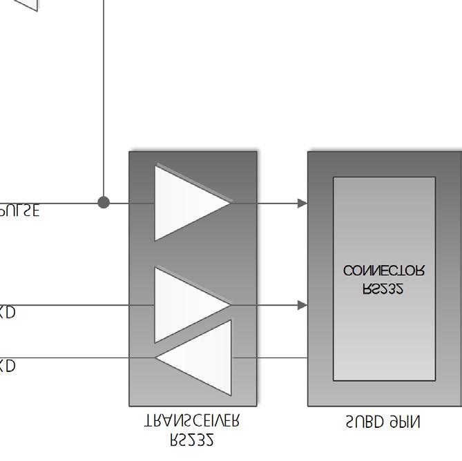

15 7 Block diagram Figure 5: EVK-7 / EVK-M8 block diagram UBX R07 Early Production Information Block diagram Page 15 of 24

16 8 Board layout Figure 6 shows the EVK-7 / EVK-M8 board layout (PCB Version B) See Table 6 for the component list of the EVB. Figure 6: EVB-7 / EVB-M8 layout UBX R07 Early Production Information Board layout Page 16 of 24
17 PART A1 BT1 C1 C14 C16 C19 C7 C10 C2 C22 C6 C8 C12 C15 C13 C3 C20 C21 C23 C24 C4 C5 D1 D2 D4 D5 D3 R17 R18 R20 R21 R22 R23 DS1 FB1 J1 J2 J3 J4 L1 L2 Q1 R1 R10 R11 R2 R6 R12 R13 R14 R15 R19 R3 R8 R24 R27 R29 R4 R5 R7 S1 S2 S3 U1 U2 U3 U7 U8 U9 U4 U5 U6 DESCRIPTION GNSS RECEIVER BATTERY HOLDER RENATA CR2450N 3 V CAP CER X7R N 10% 10 V CAP CER X5R U0 10% 6.3 V CAP CER X7R N 10% 10 V CAP CER X5R U 10% 10 V CAP CER COG P8 +/-0.1P 25 V CAP CER COG P 5% 25 V CAP CER COG P 5% 25 V CAP CER X5R N 10% 10 V CAP CER X5R U7 10% 6.3 V CAP CER X7R N0 10% 16 V SURFACE MOUNT SCHOTTKY BARRIER RECTIFIER SS14 1A -55/+125 C ESD PROTECTION FOR HIGH SPEED LINES, TYCO, 0.25PF, PESD /+125 C LED OSRAM HYPER MINI TOPLED LB M673-L1N2-35 BLUE 0.02 A FERRITE BEAD MURATA BLM15HD R@100 MHZ CON MINI USB RECEPTABLE B TYPE SMD CERTIFIED -40/+85 C CON SMA SMD STRAIGHT JACK 11.4 MM HEIGHT WITHOUT WASHER AND NUT 9 POLE SUBD CONNECTOR FEMALE 14PIN 90DEGREE 2.54MM PITCH DISCONNECTABLE CRIMP CONNECTOR -40/+85 C IND MURATA LQW15A N7 3% 0.54A -55/+125 C IND MURATA LQW15A N 5% 110mA -55/+125 C MBT3906DW1T1G DUAL GENERAL PURPOSE TRANSISTOR 0.2A 0.15W -40/+125 C RES THICK FILM CHIP R 5% 0.25 W RES THICK FILM CHIP R 5% 0.1 W RES THICK FILM CHIP R 5% 0.1 W RES THICK FILM CHIP K2 5% 0.1 W RES THICK FILM CHIP K 5% 0.1 W VARISTOR BOURNS MLE SERIES CG0402MLE-18G 18 V RES THICK FILM CHIP K 5% 0.1 W RES THICK FILM CHIP K0 5% 0.1 W RES THICK FILM CHIP R 5% 0.1 W -55/+125 C RES THICK FILM CHIP R0 5% 0.1 W SWITCH SPST ON 1POL TYCO 2 WAY SUB-MINIATURE SLIDE SWITCH SMD JS SERIES - SPDT -40/+85 C USB DATA LINE PROTECTION ST USBLC6-2SC6 SOT23-6 TINY LOGIC UHS BUFFER OE_N ACTIVE LOW FAIRCHILD NC7SZ125 SC70 LOW DROPOUT REGULATOR LINEAR LT1962 MS8 3.3V 0.3 A LOW NOISE AMPLIFIER GAAS MMIC GHZ 1.5V-3.6V JRC EPFFP6-A2 3.6V -40/+85 C RS-232 TRANSCEIVER MAXIM MAX3232 SO16-40/+85 C Table 6: EVB-7 / EVB-M8 component list UBX R07 Early Production Information Board layout Page 17 of 24


18 EVK-7 - User Guide 9 Schematic Figure 7: Schematic EVK-7 / EVK-M8: DNI=TRUE in the schematic means: Component not installed UBX R07 Early Production Information Schematic Page 18 of 24
19 10 Battery replacement To replace the battery (Number 5 in Figure 8), open the unit (unscrew four screws on the front panel). EVK-7 - User Guide Figure 8: EVK-7 / EVK-M8 battery location UBX R07 Early Production Information Battery replacement Page 19 of 24
20 EVK-7 / EVK-M8 - User Guide 11 Troubleshooting My application (e.g. u-center) does not receive anything Check whether the blue LED on the evaluation unit is blinking. Also make sure that the USB cable is properly connected to the evaluation unit and the PC. By default, the evaluation unit outputs NMEA protocol on Serial Port 1 at 9600 Bd, or on the USB. My application (e.g. u-center) does not receive all messages When using UART, make sure the baud rate is sufficient. If the baud rate is insufficient, GNSS receivers based on u-blox 7 and u-blox M8 GNSS technology will skip excessive messages. Some serial port cards/adapters (i.e. USB to RS232 converter) frequently generate errors. If a communication error occurs while u-center receives a message, the message will be discarded. My application (e.g. u-center) loses the connection to the GNSS receiver u-blox 7 / u-blox M8 positioning technology and u-center have an autobauding feature. If frequent communication errors occur (e.g. due to problems with the serial port), the connection may be lost. This happens because u-center and the GNSS receiver both autonomously try to adjust the baud rate. Do not enable the u-center autobauding feature if the GNSS receiver has the autobauding flag enabled. The COM port does not send any messages Be sure that the slide switch at the front panel is set to I2C and not SPI. In SPI Mode the RS232 pins on the DB9 connector are switched off and the RxD and TxD output at the front panel are used for SPI (MISO, MOSI). NOTE: After changing the slide switch, always reset the EVK, otherwise the change will not take place. Some COM ports are not shown in the port list of my application (e.g. u-center) Only the COM ports that are available on your computer will show up in the COM port drop down list. If a COM Port is gray, another application running on this computer is using it. The position is off by a few dozen meters u-blox 7 and u-blox M8 GNSS technology starts up with the WGS84 standard GNSS datum. If your application expects a different datum, you ll most likely find the positions to be off by a few dozen meters. Don t forget to check the calibration of u-center map files. The position is off by hundreds of meters Position drift may also occur when almanac navigation is enabled. The satellite orbit information retrieved from an almanac is much less accurate than the information retrieved from the ephemeris. With an almanac only solution, the position will only have an accuracy of a few kilometers but it may start up faster or still navigate in areas with obscured visibility when the ephemeris from one or several satellites have not yet been received. The almanac information is NOT used for calculating a position, if valid ephemeris information is present, regardless of the setting of this flag. In NMEA protocol, position solutions with high deviation (e.g. due to enabling almanac navigation) can be filtered with the Position Accuracy Mask. UBX protocol does not directly support this since it provides a position accuracy estimation, which allows the user to filter the position according to his requirements. However, the Position within Limits flag of the UBX-NAV-STATUS message indicates whether the configured thresholds (i.e. P Accuracy Mask and PDOP) are exceeded. TTFF times at startup are much longer than specified At startup (after the first position fix), the GNSS receiver performs an RTC calibration to have an accurate internal time source. A calibrated RTC is required to achieve minimal startup time. Before shutting down the receiver externally, check the status in MON-HW in field Real Time Clock Status. Do not shut down the receiver if the RTC is not calibrated. UBX R07 Early Production Information Troubleshooting Page 20 of 24

21 EVK-7 / EVK-M8 - User Guide The EVK-7 / EVK-M8 does not meet the TTFF specification Make sure the antenna has a good sky view. An obstructed view leads to prolonged startup times. In a welldesigned system, the average of the C/No ratio of high elevation satellites should be in the range of 40 dbhz to about 50 dbhz. With a standard off-the-shelf active antenna, 47 dbhz should easily be achieved. Low C/No values lead to a prolonged startup time. EVK-7 / EVK-M8 does not preserve the configuration in case of reset u-blox 7 / u-blox M8 GNSS technology uses a slightly different concept than most other GNSS receivers do. Settings are initially stored to volatile memory. In order to save them permanently, sending a second command is required. This allows testing the new settings and reverting to the old settings by resetting the receiver if the new settings aren t good. This provides safety, as it is no longer possible to accidentally program a bad configuration (e.g. disabling the main communication port). The EVK-M8CAM does not work properly when connected with a GNSS simulator When using an EVK together with a GNSS simulator, please pay attention to proper handling of the EVK. A GNSS receiver is designed for real-life use, i.e. time is always moving forward. By using a GNSS simulator, the user can change scenarios, which enables jumping backwards in time. This can have serious side effects on the performance of GNSS receivers. The solution is to configure the GPS week rollover to 1200 (as indicated in Figure 9), which corresponds to Jan Then, issue the Cold Start command before every simulator test to avoid receiver confusion due to the time jumps. Figure 9: Configuration instruction for using the EVK with a GNSS simulator Power Save Mode and USB For communication in Power Save Mode, use the RS232. EVK-7 / EVK-M8 receives GPS and GLONASS Use u-center, version 7.02 or newer. Message UBX-CFG-GNSS allows switching on and off the supported GNSS. UBX R07 Early Production Information Troubleshooting Page 21 of 24
22 EVK-7 / EVK-M8 - User Guide 12 Common evaluation pitfalls Parameter may have the same name but a different definition. GNSS receivers may have a similar size, price and power consumption but can still have different functionalities (e.g. no support for passive antennas, different temperature range). Also, the definitions of Hot, Warm, Cold Start times may differ between suppliers. Verify design-critical parameters; do not base a decision on unconfirmed numbers from datasheets. Try to use identical or at least similar settings when comparing the GNSS performance of different receivers. Data, which has not been recorded at the same time and the same place, should not be compared. The satellite constellation, the number of visible satellites and the sky view might have been different. Do not compare momentary measurements. GNSS is a non-deterministic system. The satellite constellation changes constantly. Atmospheric effects (i.e. dawn and dusk) have an impact on signal travel time. The position of the GNSS receiver is typically not the same between two tests. Comparative tests should therefore be conducted in parallel by using one antenna and a signal splitter; statistical tests shall be run for 24 hours. Monitor the Carrier-To-Noise-Ratio. The average C/No ratio of the high elevation satellites should be between 40 dbhz and about 50 dbhz. A low C/No ratio will result in a prolonged TTFF and more position drift. When comparing receivers side by side, make sure that all receivers have the same signal levels. The best way to achieve this is by using a signal splitter. Comparing results measured with different antenna types (with different sensitivity) will lead to incorrect conclusions. Try to feed the same signal to all receivers in parallel (i.e. through a splitter); the receivers won t have the same sky view otherwise. Even small differences can have an impact on the accuracy. One additional satellite can lead to a lower DOP and less position drift. When doing reacquisition tests, cover the antenna in order to block the sky view. Do not unplug the antenna since the u-blox 7 / u-blox M8 positioning technology continuously performs a noise calibration on idle channels. UBX R07 Early Production Information Common evaluation pitfalls Page 22 of 24
23 EVK-7 / EVK-M8 - User Guide Related documents [1] UBX-G7020-Kx Data Sheet, Docu. No GPS.G7-HW (NDA required) [2] UBX-G7020-CT Data Sheet, Docu. No GPS.G7-HW (NDA required) [3] NEO-7 Data Sheet, Docu. No UBX [4] NEO-7P Data Sheet, Docu. No UBX [5] MAX-7 Data Sheet, Docu. No UBX [6] EVA-7M Data Sheet, Docu. No UBX [7] UBX-G7020 Hardware Integration Manual, Docu. No UBX (NDA required) [8] MAX-7 / NEO-7 Hardware Integration Manual, Docu. No UBX [9] EVA-7M Hardware Integration Manual, Docu. No UBX [10] u-blox 7 Receiver Description including Protocol Specification, Docu. No GPS.G7-SW (Public Release), GPS.G7-SW (NDA Version) [11] UBX-M8030 Data Sheet, Docu. No UBX (NDA required) [12] UBX-M8030-ADR Data Sheet, Docu. No UBX (NDA required) [13] NEO-M8 Data Sheet, Docu. No UBX [14] MAX-M8 Data Sheet, Docu. No UBX [15] LEA-M8S Data Sheet, Docu. No UBX [16] UBX-M8030 Hardware Integration Manual, Docu. No UBX (NDA required) [17] NEO-M8 Hardware Integration Manual, Docu. No UBX [18] MAX-M8 Hardware Integration Manual, Docu. No UBX [19] u-blox M8 Receiver Description including Protocol Specification, Docu. No UBX (Public Release), UBX (NDA Version) [20] u-center User Guide, Docu. No UBX For regular updates to u-blox documentation and to receive product change notifications, register on our homepage ( Revision history Revision Date Name Status / Comments - 19-Dec khir Initial release 1 19-Mar-2013 smos Revised images of EVK Apr-2013 smos Revised specifications section 3 26-Sep-2013 amil Added EVK-7P Last revision with old document number GPS.G7-EK R05 24-Oct-2013 julu Changed to UBX document number with updated layout. R06 20-Dec-2013 mkes Changed to Advance Information status. Added EVA-7M references. Added EVK-M8 and u-blox M8 references. R07 14-May-2014 julu Updated EVK-7/EVK-M8 software download information in sections 1.3 and 3.1; Added LEA-M8S Data Sheet reference; Added an item to troubleshooting section. UBX R07 Early Production Information Related documents Page 23 of 24
24 EVK-7 / EVK-M8 - User Guide Contact For complete contact information visit us at u-blox Offices North, Central and South America u-blox America, Inc. Phone: info_us@u-blox.com Regional Office West Coast: Phone: info_us@u-blox.com Technical Support: Phone: support_us@u-blox.com Headquarters Europe, Middle East, Africa u-blox AG Phone: info@u-blox.com Support: support@u-blox.com Asia, Australia, Pacific u-blox Singapore Pte. Ltd. Phone: info_ap@u-blox.com Support: support_ap@u-blox.com Regional Office Australia: Phone: info_anz@u-blox.com Support: support_ap@u-blox.com Regional Office China (Beijing): Phone: info_cn@u-blox.com Support: support_cn@u-blox.com Regional Office China (Shenzhen): Phone: info_cn@u-blox.com Support: support_cn@u-blox.com Regional Office India: Phone: info_in@u-blox.com Support: support_in@u-blox.com Regional Office Japan: Phone: info_jp@u-blox.com Support: support_jp@u-blox.com Regional Office Korea: Phone: info_kr@u-blox.com Support: support_kr@u-blox.com Regional Office Taiwan: Phone: info_tw@u-blox.com Support: support_tw@u-blox.com UBX R07 Early Production Information Contact Page 24 of 24
EVK-7 / EVK-8 / EVK-M8
 EVK-7 / EVK-8 / EVK-M8 Evaluation Kits (PCB Version C/D) User Guide Abstract This document describes the structure and use of the EVK-7 / EVK-8 / EVK-M8 evaluation kits and provides information for evaluating
EVK-M8F Evaluation Kit time and frequency reference products. User Guide. Abstract
 EVK-M8F-0-00 Evaluation Kit time and frequency reference products User Guide Abstract This document describes the structure and use of the EVK-M8F-0-00 evaluation kit and provides information for evaluating
EVK-7 / EVK-8 / EVK-M8
 EVK-7 / EVK-8 / EVK-M8 Evaluation Kits (PCB Version C/D) User Guide Abstract This document describes the structure and use of the EVK-7 / EVK-8 / EVK-M8 evaluation kits and provides information for evaluating
EVK-M8QSAM. Evaluation Kit. User Guide. Abstract
 EVK-M8QSAM Evaluation Kit User Guide Abstract This document describes the structure and use of the EVK-M8QSAM evaluation kit and provides information for evaluating and testing the u-blox SAM-M8Q GNSS
EVK-M8xCAM. Evaluation Kits. User Guide. Abstract
 EVK-M8xCAM Evaluation Kits User Guide Abstract This document describes the structure and use of the EVK-M8QCAM and EVK-M8CCAM evaluation kits and provides information for evaluating and testing the u-blox
EVK-M8U. Evaluation Kit. User Guide. Abstract
 EVK-M8U Evaluation Kit User Guide Abstract This document describes the structure and use of the EVK-M8U evaluation kit and provides information for evaluating and testing u-blox M8 Untethered Dead Reckoning
C93-M8E. Application Board. User Guide. Abstract
 C93-M8E Application Board User Guide Abstract This document describes the structure and use of the C93-M8E application board and provides information for evaluating and testing u-blox M8 Untethered Dead
EVK-M8GZOE. Evaluation Kit. User Guide. Abstract
 EVK-M8GZOE Evaluation Kit User Guide Abstract This document describes the structure and use of the EVK-M8GZOE evaluation kit and provides information for evaluating and testing the u-blox ZOE-M8G GNSS
ANN-MB series. Multi-band, high precision GNSS antennas. Data Sheet
 ANN-MB series Multi-band, high precision GNSS antennas Data Sheet Abstract This technical data sheet describes the ANN-MB Multi-band (L1, L2/E5b) active GNSS antennas that support GPS, GLONASS, Galileo,
ANN-MS. Active GPS antenna. Data Sheet. Abstract
 ANN-MS Active GPS antenna Data Sheet Abstract The ANN active GPS antenna with integrated low-noise amplifier (LNA) is the perfect match to the u-blox GPS receivers. 48 x 40 x 13 mm www.u-blox.com Document
ANN-MB series. Multi-band, high precision GNSS antennas. Data Sheet
 ANN-MB series Multi-band, high precision GNSS antennas Data Sheet Abstract This technical data sheet describes the ANN-MB Multi-band (L1, L2/E5b) active GNSS antennas that support GPS, GLONASS, Galileo,
ANN-MS. active GPS antenna. Data Sheet. locate, communicate, accelerate. Abstract
 locate, communicate, accelerate ANN-MS active GPS antenna Data Sheet Abstract The ANN active GPS antenna with integrated low-noise amplifier (LNA) is the perfect match to the u-blox GPS receivers. 48 x
ANN-MS Active GPS Antenna
 u-blox AG Zürcherstrasse 68 8800 Thalwil Switzerland www.u-blox.com Phone +41 44 722 7444 Fax +41 44 722 7447 info@u-blox.com ANN-MS Active GPS Antenna Data Sheet Abstract The ANN active GPS antenna with
1 General Information... 3
 Release Notes Topic : GPS/GLONASS/QZSS Firmware 1.00 for u-blox 7 GPS.G7-SW-12015 Public Author : efav, uple Date : Sep. 20 th 2012 We reserve all rights in this document and in the information contained
MAX-M8. u-blox M8 Concurrent GNSS modules. Data Sheet. Highlights
 MAX-M8 u-blox M8 Concurrent GNSS modules Data Sheet Highlights Miniature LCC package (9.7x10.1x2.5 mm) Concurrent reception of GPS/QZSS, GLONASS, BeiDou u-blox AssistNow GNSS Online, Offline and Autonomous
MAX-7. u-blox 7 GNSS modules. Data Sheet. Highlights:
 MAX-7 u-blox 7 GNSS modules Data Sheet Highlights: Miniature LCC package GNSS engine for GPS/QZSS, GLONASS Low power consumption Product variants to meet performance and cost requirements Pin-to-pin and
CAM-M8C. u-blox M8 Concurrent GNSS Antenna Module. Data Sheet. Highlights:
 CAM-M8C u-blox M8 Concurrent GNSS Antenna Module Data Sheet Highlights: Concurrent reception of GPS/QZSS, GLONASS, BeiDou Miniature size and weight with low power consumption Embedded, omnidirectional
LEA-M8S. u-blox M8 concurrent GNSS module. Data Sheet. Highlights:
 LEA-M8S u-blox M8 concurrent GNSS module Data Sheet Highlights: Concurrent reception of GPS/QZSS, GLONASS, BeiDou Industry leading 167 dbm navigation sensitivity Combines low power consumption and high
Hyperion NEO-M8N GPS
 Hyperion M8N GPS Product description The M8 series of concurrent GNSS modules is built on the high performing M8 GNSS engine in the industry proven NEO form factor. The M8 modules utilize concurrent reception
NEO-7P u-blox 7 Precise Point Positioning GNSS module
 NEO-7P u-blox 7 Precise Point Positioning GNSS module Data Sheet Highlights: High precision GNSS < 1 m DGPS by SBAS or RTCM Combines low power consumption and high sensitivity Simple integration with u-blox
RY836AI. High Performance GPS & Glonass / GPS & BeiDou Parallel mode antenna module with Compass, Gyroscope, Accelerometer, Pressure Sensor.
 27-OCT-2017 56312E31 High Performance GPS & Glonass / GPS & BeiDou Parallel mode antenna module with Compass, Gyroscope, Accelerometer, Pressure Sensor Datasheet PRODUCT DESCRIPTION The REYAX GNSS receiver
GNSS 5 click PID: MIKROE-2670
 GNSS 5 click PID: MIKROE-2670 Determine your current position with GNSS 5 click. It carries the NEO- M8N GNSS receiver module from u-blox. GNSS 5 click is designed to run on a 3.3V power supply. The click
MAX-8. u-blox 8 GNSS modules. Data Sheet. Highlights
 MAX-8 u-blox 8 GNSS modules Data Sheet Highlights High sensitivity of 166 dbm for single GNSS reception Cost-efficient system TCXO-based variant for fastest time to first fix Low power consumption Superior
CONDOR C1919 GPS RECEIVER MODULE technical notes GENERAL OVERVIEW
 CONDOR C1919 GPS RECEIVER MODULE TECHNICAL HIGHLIGHTS Receiver: GPS L1 frequency (17. MHz), C/A code, -channel continuous tracking NMEA output and input: serial port On-board low noise amplifier GENERAL
PPS usable by timing applications via serial port emulation
 Timing & Navigation Module z051 USB GNSS Dongle with PPS* PPS usable by timing applications via serial port emulation * The Pulse Per Second (PPS) is an electrical signal that very precisely indicates
NEO-M8N. u-blox GNSS module. Data Sheet. Highlights:
 NEO-M8N u-blox GNSS module Data Sheet Highlights: Concurrent reception of up to 3 GNSS (GPS, Galileo, GLONASS, BeiDou) Industry leading 167 dbm navigation sensitivity Security and integrity protection
NEO-M8U. u-blox M8 Untethered Dead Reckoning module including 3D inertial sensors. Data Sheet. Highlights:
 NEO-M8U u-blox M8 Untethered Dead Reckoning module including 3D inertial sensors Data Sheet Highlights: Leading performance under poor signal conditions Continuous navigation during signal interruptions
EVA-8M and EVA-M8 series
 EVA-8M and EVA-M8 series u-blox 8 / u-blox M8 GNSS modules Hardware Integration Manual Abstract This document describes the hardware features and specifications of u-blox EVA-8M and EVA-M8 series GNSS
NEO-8Q. u-blox 8 GNSS module. Data Sheet. Highlights:
 NEO-8Q u-blox 8 GNSS module Data Sheet Highlights: High sensitivity of 166 dbm for single GNSS reception Cost-efficient system TCXO-based product enables fastest time to first fix Low power consumption
NEO-M8P. u-blox M8 High Precision GNSS Modules. Data Sheet. Highlights
 NEO-M8P u-blox M8 High Precision GNSS Modules Data Sheet Highlights Centimeter-level GNSS positioning for the mass market Integrated Real Time Kinematics (RTK) for fast time-to-market Small, light, and
SAM-M8Q. Easy-to-use u-blox M8 GNSS antenna module. Data Sheet. Smart antenna module for easy and reliable integration
 SAM-M8Q Easy-to-use u-blox M8 GNSS antenna module Data Sheet Smart antenna module for easy and reliable integration Easy to design-in with no RF expertise required Consistently strong performance regardless
CONDOR C1722 GPS RECEIVER MODULE technical notes
 CONDOR C1722 GPS RECEIVER MODULE TECHNICAL HIGHLIGHTS Receiver: GPS L1 frequency (1575.42 MHz), C/A code, 22-channel continuous tracking NMEA output and input: serial port, USB port On-board low noise
GNSS 5 click PID: MIKROE Weight: 30 g
 GNSS 5 click PID: MIKROE-2670 Weight: 30 g Determine your current position with GNSS 5 click. It carries the NEO M8N GNSS receiver module from u blox. GNSS 5 click is designed to run on a 3.3V power supply.
PAM-7Q. u-blox 7 GPS Antenna Module. Hardware Integration Manual
 PAM-7Q u-blox 7 GPS Antenna Module Hardware Integration Manual Abstract This document provides the necessary information to successfully design in and configure the PAM-7Q u-blox 7 GPS antenna module featuring
PAM-7Q. u-blox 7 GPS Antenna Module. Hardware Integration Manual
 PAM-7Q u-blox 7 GPS Antenna Module Hardware Integration Manual Abstract This document provides the necessary information to successfully design in and configure the PAM-7Q u-blox 7 GPS antenna module featuring
LEA-M8F. u-blox M8 time & frequency reference GNSS module. Data Sheet. Highlights
 LEA-M8F u-blox M8 time & frequency reference GNSS module Data Sheet Highlights Concurrent reception of GPS/QZSS, GLONASS, BeiDou Integral disciplined low phase-noise 30.72 MHz system reference oscillator
Objective Specification
 LEA-6 u-blox 6 GPS Modules Data Sheet Abstract Technical data sheet describing the cost effective, high-performance u-blox 6 based LEA-6 series of GPS modules, that bring the high performance of the u-blox
CONDOR C1216 GPS RECEIVER MODULE technical notes ZELIA INTEGRATES ANTENNA, GPS RECEIVER, RTC AND LNA
 CONDOR C1216 GPS RECEIVER MODULE technical notes Zelia GPS RECEIVER MODULE TECHNICAL HIGHLIGHTS Integrated antenna element, GPS receiver, real-time clock, and low noise amplifier Receiver: Trimble Condor
GPS Evaluation Kit EVA1084-A
 GPS Evaluation Kit EVA1084-A A Description of the Evaluation Board for Vincotech s GPS Receiver Modules A1084-A/-B User s Manual Version 1.0 Hardware Revision 01 V1.0 Jan-09 User s Manual Page 1 of 18
LEA-M8S. u-blox M8 concurrent GNSS module. Data Sheet. Highlights:
 LEA-M8S u-blox M8 concurrent GNSS module Data Sheet Highlights: Concurrent reception of up to 3 GNSS (GPS, Galileo, GLONASS, BeiDou) Industry leading 167 dbm navigation sensitivity Combines low power consumption
MAX-M8. u-blox M8 concurrent GNSS modules. Data Sheet. Highlights
 MAX-M8 u-blox M8 concurrent GNSS modules Data Sheet Highlights Concurrent reception of up to 3 GNSS (GPS, Galileo, GLONASS, BeiDou) Industry leading -167 dbm navigation sensitivity Product variants to
CONDOR C1216 GPS RECEIVER MODULE technical notes GENERAL OVERVIEW
 CONDOR C116 GPS RECEIVER MODULE technical notes CONDOR C1011 GPS RECEIVER MODULE TECHNICAL HIGHLIGHTS Receiver: GPS L1 frequency (17. MHz), C/A code, -channel continuous tracking NMEA output & input: 1
MN5020HS Smart GPS Antenna Module
 1 Description The Micro Modular Technologies MN5020HS Smart Global Positioning System (GPS) Antenna Module is a complete 20-channel receiver with an integrated 18 x 18 mm patch antenna. With this highly
GLOBALSAT GPS Engine Board
 GLOBALSAT GPS Engine Board Hardware Datasheet Product No : MT-332(SMA) Version 1.0 GlobalSat WorldCom Corporation 16F., No. 186, Jian-Yi Road, Chung-Ho City, Taipei Hsien 235, Taiwan Tel: 886-2-8226-3799
ONCORE ENGINEERING NOTE SL Oncore
 ONCORE ENGINEERING NOTE SL Oncore 1. Product Specifications 2. Basic Description 3. Mechanical 4. Electrical 5. Pin-Out Diagram 6. EMC Considerations 7. RTC (Real Time Clock) 8. 1PPS Signal Description
LEA-6. u-blox 6 GPS Modules. Data Sheet. locate, communicate, accelerate. Abstract
 locate, communicate, accelerate LEA-6 u-blox 6 GPS Modules Data Sheet Abstract Technical data sheet describing the cost effective, high-performance u-blox 6 based LEA-6 series of GPS modules, that bring
GPS Evaluation Kit EVA1035-H
 GPS Evaluation Kit EVA1035-H A Description of the Evaluation Board for Vincotech s GPS Receiver / Smart Antenna Module A1035-H User s Manual Version 1.0 Hardware Revision 01 Revision History Rev. Date
GPS/GNSS Receiver Module
 GPS/GNSS Receiver Module 1. Product Information 1.1 Product Name: YIC91612IEB9600 1.2 Product Description: YIC91612IEB9600 is a compact, high performance, and low power consumption GNSS engine board which
GAUSS High Power UHF Radio
 [] Table of contents Table of contents... 1 1. Introduction... 3 Features... 4 Block Diagram... 6 2. Pinouts... 7 3. Absolute Maximum Ratings... 9 4. General Recommended Operating Conditions... 10 5. RF
NEO/LEA-M8T. u-blox M8 concurrent GNSS timing modules. Data Sheet. Highlights:
 NEO/LEA-M8T u-blox M8 concurrent GNSS timing modules Data Sheet Highlights: Concurrent reception of GPS/QZSS, GLONASS, BeiDou Market leading acquisition and tracking sensitivity Optimized accuracy and
Ct-G551. Connectec. SiRF V GPS Module. Specifications Sheet V0.1. Features: Ct-G551 V0.1 Specification Sheet
 SiRF V GPS Module Ct-G551 Specifications Sheet V0.1 Features: SiRF StarV ultra low power chipset GPS, GLONASS, Galileo and SBAS reception for high GNSS availability and accuracy Compact module size for
NEO/LEA-M8T. u-blox M8 concurrent GNSS timing modules. Data Sheet. Highlights:
 NEO/LEA-M8T u-blox M8 concurrent GNSS timing modules Data Sheet Highlights: Concurrent reception of GPS/QZSS, GLONASS, BeiDou, Galileo Market leading acquisition and tracking sensitivity Optimized accuracy
NEO-M8. u-blox M8 GNSS modules. Hardware Integration Manual
 NEO-M8 u-blox M8 GNSS modules Hardware Integration Manual Abstract This document describes the features and specifications of the cost effective and high-performance NEO-M8 modules, which feature the u-blox
C94-M8P Application Board Setup Guide
 C94-M8P Application Board Setup Guide locate, communicate, accelerate UBX-16009722 R02 C94-M8P Board Connections and Interfaces J1 J10 J2 J3 J1: RS232 UART M8P/Radio J2: USB M8P J3: External battery /
ZOE-M8. Ultra small u-blox M8 GNSS SiPs. Data Sheet. Ultra small GNSS SiP with superior performance
 ZOE-M8 Ultra small u-blox M8 GNSS SiPs Data Sheet Ultra small GNSS SiP with superior performance Ultra small size SiP (System-in-Package) 4.5 mm x 4.5 mm x 1.0 mm Fully integrated, complete solution, reducing
YIC9 Series. GPS & BDS Receiver Module. 1. Product Information 1.1 Product Name: YIC91612EBFGB-U Product Description: Product Features:
 GPS & BDS Receiver Module 1. Product Information 1.1 Product Name: YIC91612EBFGB-U8 1.2 Product Description: YIC91612EBFGB-U8 is a flash base, compact, high performance and low power consumption, standalone
U2C-1SP4T-63H. Typical Applications
 Solid state USB / I 2 C RF SP4T Switch 50Ω 2 to 6000 MHz The Big Deal USB and I 2 C power & control High speed ing (250 ns) High power handling (+30 dbm) Very High Isolation (80 db) Small case (3.75 x
ONCORE ENGINEERING NOTE M12 Oncore
 ONCORE ENGINEERING NOTE M12 Oncore 1. Product Specifications 2. Basic Description 3. Mechanical 4. Environmental 5. Electrical 6. RF Characteristics of Receiver 7. RF Requirements for Antenna 8. Performance
MAX-7 / NEO-7. u-blox 7 GNSS modules. Hardware Integration Manual. Abstract
 MAX-7 / NEO-7 u-blox 7 GNSS modules Hardware Integration Manual Abstract This document describes the features and specifications of the cost effective and high-performance MAX-7 and NEO-7 GPS/GLONASS/QZSS
MN8010 GPS Receiver Module
 1 Description PRELIMINARY DATA SHEET The Micro Modular Technologies MN8010 Global Positioning System (GPS) Receiver Module is a complete 48-channel receiver with high sensitivity that measures only 10
QLG1 GPS Receiver kit
 QLG1 GPS Receiver kit 1. Introduction Thank you for purchasing the QRP Labs QLG1 GPS Receiver kit. This kit will provide a highly sensitive, highly accurate GPS receiver module, using the popular MediaTek
Revision WI.232FHSS-25-FCC-R and RK-WI.232FHSS-25-FCC-R USER S MANUAL
 Revision 1.0.3 WI.232FHSS-25-FCC-R and RK-WI.232FHSS-25-FCC-R USER S MANUAL RADIOTRONIX, INC. WI.232FHSS-25-FCC-R/ RK-WI.232FHSS-25-FCC-R USER S MANUAL Radiotronix 905 Messenger Lane Moore, Oklahoma 73160
GPS Application. Global Positioning System. We provide GPS module ODM / OEM service, any GPS receiver you want, we can provide customized services.
 GPS Application Global Positioning System We provide GPS module ODM / OEM service, any GPS receiver you want, we can provide customized services. www.win-tec.com.tw sales@win-tec.com.tw GNSS Receiver WGM-303
MN1818 Highly-integrated GPS Receiver Module
 1 Description The Micro Modular Technologies MN1818 Global Positioning System (GPS) Receiver is a highly-integrated, 12-channel receiver with fast-acquisition hardware intended for OEM applications. The
MC-1010 Hardware Design Guide
 MC-1010 Hardware Design Guide Version 1.0 Date: 2013/12/31 1 General Rules for Design-in In order to obtain good GPS performances, there are some rules which require attentions for using MC-1010 GPS module.
Advanced RTK GPS / Compass module with 100x100 mm ground plane and 32-bit MCU
 TGM100 Advanced RTK GPS / Compass module with 100x100 mm ground plane and 32-bit MCU Data Sheet Revision: 0.3 Date of Last Revision: 18 April 2017 True Flight Technology, Inc. ( TFT ) reserves the right
GPS & GLONASS Receiver Module
 GPS & GLONASS Receiver Module 1. Product Information 1.1 Product Name: YIC91009EBGG-U8 1.2Product Description: YIC91009EBGG-U8 is a compact, high performance and low power consumption, standalone multiple
Intro to GNSS & Teseo-LIV3F Module for IoT Positioning
 Intro to GNSS & Teseo-LIV3F Module for IoT Positioning Agenda 2 Presentation Speaker GPS Signal Overview GNSS Constellations Mike Slade Teseo3 Chipset Overview Multi-Constellation Benefit Teseo-LIV3F Module
LEA-6. u-blox 6 GPS Modules. Data Sheet. locate, communicate, accelerate. Abstract
 LEA-6 u-blox 6 GPS Modules Data Sheet locate, communicate, accelerate Abstract Technical data sheet describing the cost effective, high-performance u-blox 6 based LEA-6 series of GPS modules, that bring
di-gps Eco ProSumer PS10-M digital images GPS receiver
 di-gps Eco ProSumer PS10-M digital images GPS receiver Users Guide Ver 1.03 Please visit our website www.di-gps.com for the latest version of the user guide CONTENTS CONTENTS... 1 INTRODUCTION... 2 WARNING
LEA-6 / NEO-6 / MAX-6
 LEA-6 / NEO-6 / MAX-6 u-blox 6 GLONASS, GPS & QZSS modules Hardware Integration Manual Abstract This document describes the features and specifications of the cost effective and high-performance LEA-6,
GPS Time and Frequency Reference Receiver
 $ GPS Time and Frequency Reference Receiver Symmetricom s 58540A GPS time and frequency reference receiver features: Eight-channel, parallel tracking GPS engine C/A Code, L1 Carrier GPS T-RAIM satellite
UM2231 User manual. Teseo-LIV3F GNSS Module - Hardware Manual. Introduction
 UM2231 User manual Teseo-LIV3F GNSS Module - Hardware Manual Introduction Teseo-LIV3F is a tiny GNSS modules sized 9.7 mm 10.1 mm 2.5 mm featuring STMicroelectronics positioning receiver Teseo III. It
G3P-R232. User Manual. Release. 2.06
 G3P-R232 User Manual Release. 2.06 1 INDEX 1. RELEASE HISTORY... 3 1.1. Release 1.01... 3 1.2. Release 2.01... 3 1.3. Release 2.02... 3 1.4. Release 2.03... 3 1.5. Release 2.04... 3 1.6. Release 2.05...
1 General Information... 2
 Release Note Topic : u-blox M8 Flash Firmware 3.01 UDR 1.00 UBX-16009439 Author : ahaz, yste, amil Date : 01 June 2016 We reserve all rights in this document and in the information contained therein. Reproduction,
di-gps Eco ProSumer digital images GPS receiver
 di-gps Eco ProSumer digital images GPS receiver Users Guide Ver 1.01 Please visit our website www.di-gps.com for the latest version of the user guide CONTENTS CONTENTS... 1 INTRODUCTION... 2 WARNING /
Tel: Fax: OMESH Networks Inc. 2011
 Section 1: Purpose OPM15 is a large-scale cognitive wireless networking module, providing great flexibility for a wide range of applications. Powered by the OPM optimized radio design and networking stack,
SA-320 Installation Guide SA-320. Installation Guide. Date: Mar, 2011 Version: 2.5. All Rights Reserved
 SA-320 Installation Guide Date: Mar, 2011 Version: 2.5 All Rights Reserved Page 1 TABLE OF CONTENTS 1. Product Overview......3 1.1 Main Features...3 1.2 Applications.....3 1.3 Package Content.....3 2.
2W UHF MHz Radio Transceiver
 2W UHF410-470 MHz Radio Transceiver Specification Copyright Javad Navigation Systems, Inc. February, 2006 All contents in this document are copyrighted by JNS. All rights reserved. The information contained
LEA-M8S / LEA-M8T. u-blox M8 concurrent GNSS modules. Hardware Integration Manual
 LEA-M8S / LEA-M8T u-blox M8 concurrent GNSS modules Hardware Integration Manual Abstract This document describes the features and specifications of u-blox LEA-M8S and LEA-M8T modules. www.u-blox.com UBX-15030060
LEA-6. u-blox 6 GPS Modules. Data Sheet. locate, communicate, accelerate. Abstract
 LEA-6 u-blox 6 GPS Modules Data Sheet locate, communicate, accelerate Abstract Technical data sheet describing the cost effective, high-performance u-blox 6 based LEA-6 series of GPS modules, that bring
32-channel GPS Engine Board SmartAntenna
 32-channel GPS Engine Board SmartAntenna with MTK Chipset The document is the exclusive property of and should not be distributed, reproduced, or any other format without prior permission of Specifications
Smart Design Technology Co., Ltd.
 Mars700Mini-TMC GNS TC5000 TMC Module Smart Design Technology Co., Ltd. 20F-8, No.107, Sec 1,Jhongshan Rd. Sinjhuang City, Taipei County 242, Taiwan Phone: +886-2-8522-7628 Fax: +886-2-8522-7784 Contact:
ZICM35xSPx Hardware Design Guidelines
 Application Note 0011-00-16-09-000 ZICM35xSPx Hardware Design Guidelines Document No: 0011-00-16-09-000 (Issue C) INTRODUCTION This Application Note provides module placement, schematic design examples
SPECIFICATIONS SUBJECT TO CHANGE WITHOUT NOTICE
 SPECIFICATIONS SUBJECT TO CHANGE WITHOUT NOTICE Notice While reasonable efforts have been made to assure the accuracy of this document, Telit assumes no liability resulting from any inaccuracies or omissions
SPECIFICATION. GPS Receiver Module PMB-248 ISSUED DATE 2005/09/14 PUBLISHED BY VERSION 01 PAGE 2/7 PRODUCT NAME. Polstar Technologies Inc.
 PAGE 2/7 SPECIFICATION SPEC NO. : PMB-248 PART NO. : PMB-248 : GPS Receiver / PMB-248 DESCRIPTION : GPS Receiver (RS232,TTL, Baud Rate 4800bps) REVISION STATUS VERSION DATE PAGE REVISION DESCRIPTION PREPARED
LEA-6 / NEO-6 / MAX-6
 locate, communicate, accelerate LEA-6 / NEO-6 / MAX-6 u-blox 6 GLONASS, GPS & QZSS modules Hardware Integration Manual Abstract This document describes the features and specifications of the cost effective
GAM-2107-MTR GPS Antenna Module. General Description. The Gotop GAM-2107-MTR is a complete. GPS engine module that features super sensitivity,
 General Description The Gotop GAM-2107-MTR is a complete GPS engine module that features super sensitivity, ultra low power and small form factor. The GPS signal is applied to the antenna input of module,
High power radio transmission module MR03 type
 High power radio transmission module MR03 type User s manual CONTENTS 1. APPLICATION...3 2. MR03 MODULE SET...4 3. INSTALLATION...4 3.1 Module assembly...4 3.2 Connection diagrams...5 3.3 Connection way
MC-1612 Hardware Design Guide
 LOCOSYS Technology Inc. MC-1612 Hardware Design Guide Version 1.0 Date: 2013/09/17 LOCOSYS Technology Inc. 1 General Rules for Design-in In order to obtain good GPS performances, there are some rules which
GPS Engine Board USB Interface
 GPS Engine Board USB Interface Specification DGM-U2525B Page 1 of 14 1. Introduction 1.1. Overview The DGM-U2525B is a high sensitivity ultra low power consumption cost efficient, compact size GPS engine
Manual. LEA-5 u-blox 5 GPS and GALILEO Modules. Hardware Integration Manual (incl. Reference Design) your position is our focus
 your position is our focus") u-blox AG Zürcherstrasse 68 8800 Thalwil Switzerland www.u-blox.com Phone +41 44 722 7444 Fax +41 44 722 7447 info@u-blox.com LEA-5 u-blox 5 GPS and GALILEO Modules Hardware Integration Manual (incl. Reference
u-blox AG Zürcherstrasse 68 8800 Thalwil Switzerland www.u-blox.com Phone +41 44 722 7444 Fax +41 44 722 7447 info@u-blox.com LEA-5 u-blox 5 GPS and GALILEO Modules Hardware Integration Manual (incl. Reference
nrf905-evboard nrf905 Evaluation board PRODUCT SPECIFICATION GENERAL DESCRIPTION
 nrf905 Evaluation board nrf905-evboard GENERAL DESCRIPTION This document describes the nrf905-evboard and its use with the Nordic Semiconductor nrf905 Single Chip 433/868/915MHz RF Transceiver. nrf905-
GP-2117 GPS&GLONASS Antenna Module
 General Description The ADH-Tech GP-2117 is a complete GPS&GLONASS engine module that features super sensitivity, ultra low power and small form factor. The GPS&GLONASS signal is applied to the antenna
L76-L GNSS Module Presentation
 L76-L GNSS Module Presentation May, 2016 Quectel Wireless Solutions Co., Ltd. All rights reserved www.quectel.com Contents Highlights Advanced Features Quectel L76-L vs. Competitor s Product Support Package
66-Channel GPS Module GP-3711
 66-Channel GPS Module with MTK Chipset GP-3711 Low power consumption version 1 History Date Rev. Description 2013/12/31 A00 First Release 2 Description The GP-3711 is a ROM-based mini GPS module which
NEO-8Q / NEO-M8. u-blox 8 / M8 GNSS modules. Hardware Integration Manual
 NEO-8Q / NEO-M8 u-blox 8 / M8 GNSS modules Hardware Integration Manual Abstract This document describes the features and specifications of u-blox NEO-8Q and NEO-M8 series modules. www.u-blox.com UBX-15029985
MINI-32. development board for PIC32MZ MINI ARM. PIC32 development board fitted in a DIP40 form factor, containing a powerful microcontroller.
 MINI-32 development board for PIC32MZ PIC32 development board fitted in a DIP40 form factor, containing a powerful microcontroller. MINI ARM TO OUR VALUED CUSTOMERS I want to express my thanks to you for
EB-230. Ultimate TRANSYSTEM INC. EB-230 Data Sheet
 GPS Engine Board EB-230 Data Sheet EB-230 EB-230 is an ultra miniature 12 x 12 mm 2 GPS engine board. It provides superior navigation performance under dynamic conditions in areas with limited sky view
L50 GPS Module Presentation
 Quectel Wireless Solutions Wireless Module Expert L50 GPS Module Presentation April 2013 Contents L50 General description - New Features - Product Advantages - Mechanical Dimensions - Hardware Architecture