Go to: Circuits Go to: 100 IC Circuits
|
|
|
- Gabriel Merritt
- 5 years ago
- Views:
Transcription


1 Go to: Circuits Go to: 100 IC Circuits See TALKING ELECTRONICS WEBSITE Colin Mitchell:
2 INTRODUCTION This e-book contains 100 transistor circuits. The second part of this e-book will contain a further 100 circuits. Most of them can be made with components from your "junk box" and hopefully you can put them together in less than an hour. The idea of this book is to get you into the fun of putting things together and there's nothing more rewarding than seeing something work. It's amazing what you can do with a few transistors and some connecting components. And this is the place to start. Most of the circuits are "stand-alone" and produce a result with as little as 5 components. We have even provided a simple way to produce your own speaker transformer by winding turns on a piece of ferrite rod. Many components can be obtained from transistor radios, toys and other pieces of discarded equipment you will find all over the place. To save space we have not provided lengthy explanations of how the circuits work. This has already been covered in TALKING ELECTRONICS Basic Electronics Course, and can be obtained on a CD for $10.00 (posted to anywhere in the world) See Talking Electronics website for more details: Transistor data is at the bottom of this page and a transistor tester circuit is also provided. There are lots of categories and I am sure many of the circuits will be new to you, because some of them have been designed recently by me. Basically there are two types of transistor: PNP and NPN. All you have to do is identify the leads of an unknown device and you can build almost anything. You have a choice of building a circuit "in the air," or using an experimenter board (solderless breadboard) or a matrix board or even a homemade printed circuit board. The choice is up to you but the idea is to keep the cost to a minimum - so don't buy anything expensive. If you take parts from old equipment it will be best to solder them together "in the air" (as they will not be suitable for placing on a solderless breadboard as the leads will be bent and very short). This way they can be re-used again and again. No matter what you do, I know you will be keen to hear some of the "noisy" circuits in operation. Before you start, the home-made Speaker Transformer project and Transistor Tester are the first things you should look at. If you are starting in electronics, see the World's Simplest Circuit. It shows how a transistor works and three transistors in the 6 Million Gain project will detect microscopic levels of static electricity! You can look through the Index but the names of the projects don't give you a full description of what they do. You need to look at everything. And I am sure you will. KIT OF PARTS Talking Electronics supplies a kit of parts that can be used to build the majority of the circuits in this book. The kit costs $15.00 plus postage. In many cases, a resistor or capacitor not in the kit, can be created by putting
3 two resistors or capacitors in series or parallel or the next higher or lower value can be used. Don't think transistor technology is obsolete. Many complex circuits have one or more transistors to act as buffers, amplifiers or to connect one block to another. It is absolutely essential to understand this area of electronics if you want to carry out design-work or build a simple circuit to carry out a task. CONTENTS circuits in red are in Circuits
4 Ammeter 0-1A Automatic Garden Light Automatic Light Battery Monitor MkI Battery Monitor MkII Bench Power Supply Bike Turning Signal Beacon (Warning Beacon 12v) Beeper Bug Book Light Boom Gate Lights Boxes Buck Converter for LEDs 48mA Buck Converter for LEDs 170mA Buck Converter for LEDs 210mA Cable Tracer Camera Activator Circuit Symbols Complete list of Symbols Clock - Make Time Fly Clap Switch Colour Code for Resistors - all resistors Colpitts Oscillator Constant Current Constant Current Source Continuity Tester Dancing Flower Dark Detector with beep Alarm Decaying Flasher Door-Knob Alarm Dynamic Microphone Amplifier Electronic Drums Fading LED Flasher (simple) Flashing Beacon (12v Warning Beacon) Flashing LED - and see 3 more in this list Fog Horn FRED Photopopper Gold Detector Guitar Fuzz Hartley Oscillator Hex Bug Power Supplies - Adjustable 78xx series Power Supplies - Adjustable from 0v PWM Controller Quiz Timer Railway time Random Blinking LEDs Resistor Colour Code Resistor Colour Code Resistor Colour Code - 4, 5 and 6 Bands Reversing a Motor Robo Roller Robot Robot Man - Multivibrator Schmitt Trigger SCR with Transistors Second Simplest Circuit Sequencer Shake Tic Tac LED Torch Signal by-pass Signal Injector Simple Flasher Simple Logic Probe Simple Touch-ON Touch-OFF Switch Siren Siren Soft Start power supply Solar Engine Solar Engine Type-3 Solar Photovore Sound to Light Sound Triggered LED Speaker Transformer Spy Amplifier Strength Tester Sun Eater-1 Sun Eater-1A Super Ear Ticking Bomb Touch-ON Touch-OFF Switch Touch Switch Tracking Transmitter
5 H-Bridge Heads or Tails Hearing Aid Constant Volume Hearing Aid Push-Pull Output Hearing Aid 1.5v Supply Hee Haw Siren IC Radio Increasing the output current Intercom Latching Relay LED Detects Light LED Detects light LED Flasher - and see 3 more in this list LED Flasher 1-Transistor LED Torch with Adj Brightness LED Torch with 1.5v Supply LED 1-watt LED 1.5 watt LED Driver 1.5v White LED LED flasher 3v White LED Lie Detector Light Alarm-1 Light Alarm-2 Light Alarm-3 Light Extender for Cars Limit Switches Listener - phone amplifier Logic Probe - Simple Logic Probe with Pulse Low fuel Indicator Mains Night Light Make any resistor value Make Time Fly! Making 0-1A Ammeter Metal Detector Microphone Pre-amplifier Model Railway time Motor Speed Controller Movement Detector Multimeter - Voltage of Bench Supply Music to Colour On-Off via push Buttons Phaser Gun Phone Alert Track Polarity - model railway Train Detectors Train Throttle Transformerless Power Supply Transistor Pinouts Transistor Tester-1 Transistor Tester-2 Trickle Charger 12v Voltage Multipliers Wailing Siren Walkie Talkie Walkie Talkie with LM386 Walkie Talkie - 5 Tr - circuit 1 Walkie Talkie - 5 Tr- circuit 2 Worlds Simplest Circuit White LED Flasher White LED with Adj Brightness White Line Follower Zener Diode (making) 0-1A Ammeter 1-watt LED 1.5 watt LED 1.5v to 10v Inverter 1.5v LED Flasher 1.5v White LED Driver 3-Phase Generator 3v White LED flasher 5v from old cells 5 LED Chaser 5 Transistor Radio 5v Regulated Supply from 3v 6 Million Gain 6 to 12 watt Fluoro Inverter 12v Flashing Beacon (Warning Beacon) 12v Relay on 6v 12v Trickle Charger 20 LEDs on 12v supply 20watt Fluoro Inverter 27MHz Door Phone 27MHz Transmitter 27MHz Transmitter - no Xtal 27MHz Transmitter-Sq Wave 27MHz Transmitter-2 Ch 27MHz Transmitter-4 Ch 27MHz Receiver
6 Phone Tape-1 Phone Tape-2 Phone Tape-3 Phone Transmitter-1 Phone Transmitter-2 Phase-shift Oscillator Power Supplies - Fixed Power Supplies - Adjustable LMxx series 27MHz Receiver-2 303MHz Transmitter

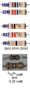
7 RESISTOR COLOUR CODE See resistors from 0.22ohm to 22M in full colour at bottom of this page and another resistor table


8 BOXES FOR PROJECTS One of the most difficult things to find is a box for a project. Look in your local "junk" shop, $2.00 shop, fishing shop, and toy shop. And in the medical section, for handy boxes. It's surprising where you will find an ideal box. The photo shows a suitable box for a Logic Probe or other design. It is a toothbrush box. The egg shaped box holds "Tic Tac" mouth sweeteners and the two worm reduction twists a "Chuppa Chub." It cost less than $4.00 and the equivalent reduction in a hobby shop costs up to $16.00! A two-worm reduction gearbox producing a reduction of 12:1 and 12:1 = 144:1 The gears are in the correct positions to produce the reduction. The speaker transformer is made by winding 50 turns of 0.25mm wire on a small length of 10mm dia ferrite rod. The size and length of the rod does not matter - it is just the number of turns that makes the transformer work. This is called the secondary winding. The primary winding is made by winding 300 turns of 0.01mm wire (this is very fine wire) over the secondary and ending with a loop of wire we call the centre tap. Wind another 300 turns and this completes the transformer. It does not matter which end of the secondary is connected to the top of the speaker. It does not matter which end of the primary is connected to the collector of the transistor in the circuits in this book.
9 SUPER EAR This circuit is a very sensitive 3-transistor amplifier using a speaker transformer. This can be wound on a short length of ferrite rod as show above or 150 turns on a 10mH choke. The biasing of the middle transistor is set for 3v supply. The second and third transistors are not turned on during idle conditions and the quiescent current is just 5mA. The project is ideal for listening to conversations or TV etc in another room with long leads connecting the microphone to the amplifier.

10 TRANSISTOR TESTER- 1 CIRCUIT 10mH choke with 150 turns for the secondary The TRANSISTOR TESTER - 1 Transistor Tester - 1 project will test all types of transistors including Darlington and power. The circuit is set to test NPN types. To test PNP types, connect the 9v battery around the other way at points A and B. The transformer in the photo is a 10mH choke with 150 turns of 0.01mm wire wound over the 10mH winding. The two original pins (with the red and black leads) go to the primary winding and the fine wires are called the Sec. Connect the transformer either way in the circuit and if it does not work, reverse either the primary or secondary (but not both). Almost any transformer will work and any speaker will be suitable. If you use the speaker transformer described in the Home Made Speaker Transformer article, use one-side of the primary. TRANSISTOR TESTER - 2 Here is another transistor tester. This is basically a high gain amplifier with feedback that causes the LED to flash at a rate determined by the 10u and 330k resistor. Remove one of the transistors and insert the unknown transistor. When it is NPN with the pins as shown in the photo, the LED will flash. To turn the unit off, remove one of the transistors.


11 WORLDS SIMPLEST CIRCUIT This is the simplest circuit you can get. Any NPN transistor can be used. Connect the LED, 220 ohm resistor and transistor as shown in the photo. Touch the top point with two fingers of one hand and the lower point with fingers of the other hand and squeeze. The LED will turn on brighter when you squeeze harder. Your body has resistance and when a voltage is present, current will flow though your body (fingers). The transistor is amplifying the current through your fingers about 200 times and this is enough to illuminate the LED. SECOND SIMPLEST CIRCUIT This the second simplest circuit in the world. A second transistor has been added in place of your fingers. This transistor has a gain of about 200 and when you touch the points shown on the diagram, the LED will illuminate with the slightest touch. The transistor has amplified the current (through your fingers) about 200 times.


12 6 MILLION GAIN! This circuit is so sensitive it will detect "mains hum. Simply move it across any wall and it will detect wh the mains cable is located. It has a gain of about x 200 = 6,000,000 and will also detect static electricity and the presence of your hand without an direct contact. You will be amazed what it detects! There is static electricity EVERYWHERE! The inpu this circuit is classified as very high impedance. Here is a photo of the circuit, produced by a constructor, where he claimed he detected "ghosts

13 The circuit uses a flashing LED to flash a super-bright 20,000mcd white LED LED FLASHER WITH ONE TRANSISTOR! This is a novel flasher circuit using a single driver transistor that takes its flashrate from a flashing LED. The flasher in the photo is 3mm. An ordinary LED will not work. The flash rate cannot be altered by the brightness of the high-bright white LED can be adjusted by altering the 1k resistor across the 100u electrolytic to 4k7 or 10k. The 1k resistor discharges the 100u so that when the transistor turns on, the charging current into the 100u illuminates the white LED. If a 10k discharge resistor is used, the 100u is not fully discharged and the LED does not flash as bright. All the parts in the photo are in the same places as in the circuit diagram to make it easy to see how the parts are connected. 1.5v LED FLASHER This will flash a LED, using a single 1.5v cell. It will even flash a white LED even though this type of LED needs about 3.2v to 3.6v for operation. The circuit takes about 2mA but produces a very bright flash.
14 3v WHITE LED FLASHER This will flash a white LED, on 3v supply and produce a very bright flash. The circuit produces a voltage higher than 5v if the LED is not in circuit but the LED limits the voltage to its characteristic voltage of 3.2v to 3.6v. The circuit takes about 2mA an is actually a voltage-multiplier arrangement. Note the 10k in series with the LED charges the 100u. It does not illuminate the LED because the 100u is charging and the voltage across it is always less than 3v. When the two transistors conduct, the collector of the BC557 rises to rail voltage and pulls the 100u HIGH. The negative of the 100u effectively sits on top of the positive rail and the positive of the electro is about 2v higher than this. All the energy in the electro is pumped into the LED to produce a very bright flash. DANCING FLOWER This circuit was taken from a dancing flower. A motor at the base of the flower had a shaft up the stem and when the microphone detected music, the bent shaft made the flower wiggle and move. The circuit will respond to a whistle, music or noise. WHITE LINE FOLLOWER This circuit can be used for a toy car to follow a white line. The motor is either a 3v type with gearing to steer the car or a rotary actuator or a servo motor. When equal light is detected by the photo resistors the voltage on the base of the first transistor will be mid rail and the circuit is adjusted via the 2k2 pot so the motor does not receive any voltage. When one of the LDR's receives more (or less) light, the motor is activated. And the same
15 thing happens when the other LDR receives less or more light. LED DETECTS LIGHT All LEDs give off light of a particular colour but some LEDs are also able to detect light. Obviously they are not as good as a device that has been specially made to detect light; such as solar cell, photocell, photo resistor, light dependent resistor, photo transistor, photo diode and other photo sensitive devices. A green LED will detect light and a high-bright red LED will respond about 100 times better than a green LED, but the LED in this position in the circuit is classified as very high impedance and it requires a considerable amount of amplification to turn the detection into a worthwhile current-source. All other LEDs respond very poorly and are not worth trying. The accompanying circuit amplifies the outp ut of the LED and enables it to be used for a number of applications. The LED only responds when the light enters the end of the LED and this makes it ideal for solar trackers and any time there is a large difference between the dark and light conditions. It will not detect the light in a room unless the lamp is very close. 12v RELAY ON 6V SUPPLY This circuit allows a 12v relay to operate on a 6v or 9v supply. Most 12v relays need about 12v to "pull-in" but will "hold" on about 6v. The 220u charges via the 2k2 and bottom diode. When an input above 1.5v is applied to the input of the circuit, both transistors are turned ON and the 5v across the electrolytic causes the negative end of the electro to go below the 0v rail by about 4.5v and this puts about 10v across the relay. Alternatively you can rewind a 12v relay by removing about half the turns. Join up what is left to the terminals. Replace the turns you took off, by connecting them in parallel with the original half, making sure the turns go the same way around


16 MAKE TIME FLY! Connect this circuit to an old electronic clock mechanism and speed up the motor 100 times! The "motor" is a simple "stepper-motor" that performs a half-rotation each time the electromagnet is energised. It normally takes 2 seconds for one revolution. But our circuit is connected directly to the winding and the frequency can be adjusted via the pot. Take the mechanism apart, remove the 32kHz crystal and cut one track to the electromagnet. Connect the circuit below via wires and re-assemble the clock. As you adjust the pot, the "seconds hand" will move clockwise or anticlockwise and you can watch the hours "fly by" or make "time go backwards." The multivibrator section needs strong buffering to drive the 2,800 ohm inductive winding of the motor and that's why push-pull outputs have been used. The flip-flop circuit cannot drive the highly inductive load directly (it upsets the waveform enormously). From a 6v supply, the motor only gets about 4v due to the voltage drops across the transistors. Consumption is about 5mA. HOW THE MOTOR WORKS The rotor is a magnet with the north pole shown with the red mark and the south pole opposite. The electromagnet actually produces poles. A strong North near the end of the electromagnet, and a weak North at the bottom. A strong South at the top left and weak South at bottom left. The rotor rests with its poles being attracted to the 4 pole-pieces equally. The crystal removed and a "cut track" to the coil. The 6 gears must be re-fitted for the hands to work. Voltage must be applied to the electromagnet around the correct way so that repulsion occurs. Since the rotor is sitting equally between the North poles, for example, it will see a strong pushing force from the pole near the electromagnet and this is how the motor direction is determined. A reversal of voltage will revolve the rotor in the same direction as before. The design of the motor is much more complex than you think!! A close-up of the clock motor Another clock motor is shown below. Note the pole faces spiral closer to the rotor to make it revolve in one direction. What a clever design!!

17 CONSTANT CURRENT SOURCE This circuit provides a constant current to the LED. The LED can be replaced by any other component and the current through it will depend on the value of R2. Suppose R2 is 560R. When 1mA flows through R2, 0.56v will develop across this resistor and begin to turn on the BC547. This will rob the base of BD 679 with turn-on voltage and the transistor turns off slightly. If the supply voltage increases, this will try to increase the current through the circuit. If the current tries to increase, the voltage across R2 increases and the BD 679 turns off more and the additional voltage appears across the BD 679. If R2 is 56R, the current through the circuit will be 10mA. If R2 is 5R6, the current through the circuit will be 100mA - although you cannot pass 100mA through a LED without damaging it. ON - OFF VIA MOMENTARY PUSH-BUTTONS This circuit will supply current to the load R L. The maximum current will depend on the second transistor. The circuit is turned on via the "ON" push button and this action puts a current through the load and thus a voltage develops across the load. This voltage is passed to the PNP transistor and it turns ON. The collector of the PNP keeps the power transistor ON. To turn the circuit OFF, the "OFF" button is pressed momentarily. The 1k between base and emitter of the power transistor prevents the base floating or receiving any slight current from the PNP transistor that would keep the circuit latched ON. The circuit was originally designed by a Professor of Engineering at Penn State University. It had 4 mistakes. So much for testing a circuit!!!! It has been corrected in the circuit on the left.

18 SIREN This circuit produces a wailing or siren sound that gradually increases and decreases in frequency as the 100u charges and discharges when the push-button is pressed and released. In other words, the circuit is not automatic. You need to press the button and release it to produce the up/down sound. TICKING BOMB This circuit produces a sound similar to a loud clicking clock. The f requency of the tick is adjusted by the 220k pot. T he circuit starts by charging the 2u2 and when 0.65v is on the base of t he NPN transistor, it starts to turn on. This turns on the BC 557 and t he voltage on the collector rises. This pushes the small charge on the 2 u2 into the base of the BC547 to turn it on more. T his continues when the negative end of the 2u2 is above 0.65v and n ow the electro starts to charge in the opposite direction until both transistors are fully turned on. The BC 547 receives less current into the base and it starts to turn off. Both transistors turn off very quickly and the cycle starts again. LIE DETECTOR This circuit detects the resistance between your fingers to produce an oscillation. The detection- points will detect resistances as high as 300k and as the resistance decreases, the frequency increases. Separate the two touch pads and attach them to the back of each hand. As the subject feels nervous, he will sweat and change the frequency of the circuit. The photos show the circuit built on PC boards with separate touch pads.

19 TOUCH SWITCH This circuit detects the skin resistance of a finger to deliver a very small current to the super-alpha pair of transistors to turn the circuit ON. The output of the "super transistor" turns on the BC 557 transistor. The voltage on the top of the globe is passed to the front of the circuit via the 4M7 to take the place of your finger and the circuit remains ON. To turn the circuit OFF, a finger on the OFF pads will activate the first transistor and this will rob the "super transistor" of voltage and the circuit will turn OFF. SIGNAL INJECTOR This circuit is rich in harmonics and is ideal for testing amplifier circuits. To find a fault in an amplifier, connect the earth clip to the 0v rail and move through each stage, starting at the speaker. An increase in volume should be heard at each preceding stage. This Injects will also go through the IF stages of radios and FM sound sections in TV's. LIGHT ALARM - 1 This circuit operates when the Light Dependent Resistor receives light. When no light falls on the LDR, its resistance is high and the transistor driving the speaker is not turned on. When light falls on the LDR its resistance decreases and the collector of the second transistor falls. This turns off the first transistor slightly via the second 100n and the first 100n puts an additional spike into the base of the second transi stor. This continues until the second transistor is turned on as hard as it can go. The first 100n is now nearly charged and it cannot keep the second transistor turned on. The second transistor starts to turn off and both transistors swap conditions to produce the second half of the cycle.
20 LIGHT ALARM - 2 This circuit is similar to Light Alarm -1 but produces a louder output due to the speaker being connected directly to the circuit. The circuit is basically a high-gain amplifier that is turned on initially by the LDR and then the 10n keeps the circuit turning on until it can turn on no more. The circuit then starts to turn off and eventually turns off completely. The current through the LDR starts the cycle again. LIGHT ALARM - 3 (MOVEMENT DETECTOR) This circuit is very sensitive and can be placed in a room to detect the movement of a person up to 2 metres from the unit. The circuit is basically a high-gain amplifier (made up of the first three transistors) that is turned on by the LDR or photo Darlington transistor. The third transistor charges the 100u via a diode and this delivers turn-on voltage for the oscillator. The LDR has equal sensitivity to the photo transistor in this circuit. SOUND TRIGGERED LED This circuit turns on a LED when the microphone detects a loud sound. The "charge-pump" section consists of the 100n, 10k, signal diode and 10u electrolytic. A signal on the collector of the first transistor is passed to the 10u via the diode and this turns on the second transistor, to illuminate the LED.
21 SIMPLE LOGIC PROBE This circuit consumes no current when the probe is not touching any circuitry. The reason is the voltage across the green LED, the base-emitter junction of the BC557, plus the voltage across the red LED and base-emitter junction of the BC547 is approx: 2.1v + 0.6v + 1.7v + 0.6v = 5v and this is greater than the supply voltage. When the circuit detects a LOW, the BC557 is turned on and the green LED illuminates. When a HIGH ( above 2.3v) is detected, the red LED is illuminated. LOGIC PROBE with PULSE This circuit has the advantage of providing a PULSE LED to show when a logic level is HIGH and pulsing at the same time. It can be built for less than $5.00 on a piece of matrix board or on a small strip of copper clad board if you are using surface mount components. The probe will detect a HIGH at 3v and thus the project can be used for 3v, 5v and CMOS circuits. CONTINUITY TESTER This circuit has the advantage of providing a beep when a short-circuit is detected but does not detect the small voltage drop across a diode. This is ideal when testing logic circuits as it is quick and you can listen for the beep
22 while concentrating on the probe. Using a multimeter is much slower. TRAIN THROTTLE This circuit is for model train enthusiasts. By adding this circuit to your speed controller box, you will be able to simulate a train starting slowly from rest. Remove the wire-wound rheostat and replace it with a 1k pot. This controls the base of the BC547 and the 2N3055 output is controlled by the BC547. The diodes protect the transistors from reverse polarity from the input and spikes from the rails. GUITAR FUZZ The output of a guitar is connected to the input of the Fuzz circuit. The output of this circuit is connected to the input of your amplifier. With the guitar at full volume, this circuit is overdriven and distorts. The distorted signal is then clipped by the diodes and your power amp amplifies the Fuzz effect. STRENGTH TESTER This is a simple "staircase" circuit in which the LEDs come on as the resistance between the probes decreases. When the voltage on the base of the first transistor sees 0.6v + 0.6v + 0.6v = 1.8v, LED1 comes on. LEDs 1&2 will come on when the voltage rises a further 0.6v. The amount of pressure needed on the probes to produce a result, depends on the setting of the 200k pot.
23 FOG HORN When the push-button is pressed, the 100u will take time to charge and this will provide the rising pitch and volume. When the push-button is released, the level and pitch will die away. This is the characteristic sound of a ship's fog horn. HEADS OR TAILS When the push-button is pressed, the circuit will oscillate at a high rate and both LEDs will illuminate. When the push button is released, one of the LEDs will remain illuminated. The 50k is designed to equalise the slightly different values on each half of the circuit and prevent a "bias." ROBOT MAN This multivibrator circuit will flash the Robot Man's eyes as shown in the photo. The kit of components is available from Talking Electronics for $8.50 plus postage. Send an to find out the cost of postage: talking@tpg.com.au
24 DYNAMIC MICROPHONE AMPLIFIER This circuit takes the place of an electret microphone. It turns an ordinary mini speaker into a very sensitive microphone. Any NPN transistors such as BC 547 can be used. The circuit will work from 3v to 9v. It is a common-base amplifier and accepts the low impedance of the speaker to produce a gain of more than 100. SCR WITH TRANSISTORS The SCR in circuit A produces a 'LATCH.' When the button is pressed, the LED remains illuminated. The SCR can be replaced with two transistors as shown in circuit B. To turn off circuit A, the current through the SCR is reduced to zero by the action of the OFF button. In circuit B the OFF button removes the voltage on the base of the BC547. The OFF button could be placed across the two transistors and the circuit will turn off.
25 HEE HAW SIREN The circuit consists of two multivibrators. The first multi-vibrator operates at a low frequency and this provides the speed of the change from Hee to Haw. It modifies the voltage to the tone multivibrator, by firstly allowing full voltage to appear at the bottom of the 220R and then a slightly lower voltage when the LED is illuminated. MICROPHONE PRE-AMPLIFIER This circuit consists of two directly coupled transistors operating as common-emitter amplifiers. The ratio of the 10k resistor to the 100R sets the gain of the circuit at 100. HARTLEY OSCILLATOR The Hartley Oscillator is characterised by an LC circuit in its collector. The base of the transistor is held steady and a small amount of signal is taken from a tapping on the i nductor and fed to the emitter to keep the transistor in oscillation. The transformer can be any speaker transformer with centre-tapped primary. The frequency is adjusted by changing the 470p. COLPITTS OSCILLATOR The Colpitts Oscillator is characterised by tapping the midthe capacitive side of the point of oscillator section. The inductor can be the primary side of a speaker transformer. The feedback comes via the inductor.

26 PHASESHIFT OSCILLATOR The Phaseshift Oscillator is characterised by 3 high-pass filters, creating a 180 phase shift. The output is a sinewave. Take care not to load the output - this will prevent reliable start- from oscillating. up and may stop the circuit Reduced the 3k3 load resistor if the load prevents the circuit oscillating. See Phase Shift Oscillator in section section of 200 Transistor Circuits for a better design. DOOR-KNOB ALARM This circuit can be used to detect when someone touches the handle of a door. A loop of bare wire is connected to the point "touch plate" and the project is hung on the door-knob. Anyone touching the metal door-knob will kill the pulses going to the second transistor and it will turn off. This will activate the "high-gainamplifier/oscillator. The circuit will also work as a "Touch Plate" as it does not rely on main hum, as many other circuits do. MOTOR SPEED CONTROLLER Mos t simple motor speed controllers simply reduce the v oltage to a motor by introducing a series resistance. This reduces the motor's torque and if the motor is stopped, it will not start again. This circuit detects the pulses of noise produced by the motor to turn the circuit off slightly. If the motor becomes loaded, the amplitude of the pulses decreases and the circuit turns on more to deliver a higher current.
27 ELECTRONIC DRUMS The circuit consists of two "twin-t" oscillators set to a point below oscillation. Touching a Touch Pad will set the circuit into oscillation. Different effects are produced by touching the pads in different ways and a whole range of effects are available. The two 25k pots are adjusted to a point just before oscillation. A "drum roll" can be produced by shifting a finger rapidly across adjacent ground and drum pads. LIGHT EXTENDER This circuit is a Courtesy Light Extender for cars. It extends the "ON" ti me when a door is closed in a car, so the passenger can see where he/she is sitting. When the door switch is opened, the light normally goes off immediate ly, but the circuit takes over and allows current to flow because the 22u is not charged and the first BC 547 transistor is not turned ON. This tur ns on the second BC547 via the 100k and the BD679 is also turned on to illuminate the interior light. The 22u gradually charges via the 1M and the first BC547 turns on, ro bbing the second BC547 of "turn-on" voltage and it starts to turn off the BD679. The 1N4148 discharges the 22u when the door is opened.
28 20 WATT FLUORO INVERTER This circuit will drive a 40 watt fluoro or two 20- watt tubes in series. The transformer is wound on a ferrite rod 10mm dia and 8cm long. The wire diameters are not critical but our prototype used 0.61mm wire for the primary and 0.28mm wire for the secondary and feedback winding. Do not remove the tube when the circuit is operating as the spikes produced by the transformer will damage the transistor. The circuit will take approx 1.5amp on 12v, making it more efficient than running the tubes from the mains. A normal fluoro takes 20 watts for the tube and about 15 watts for the ballast. 6 to 12 WATT FLUORO INVERTER This circuit will drive a 40 watt fluoro or two 20-watt tubes in series but with less brightness than the circuit above and it will take less current. 2 x 20 watt tubes = 900mA to 1.2A and 1 x 20 watt tube 450mA to 900mA depending on pot setting. The transformer is wound on a ferrite rod 10mm dia and 8cm long. The wire diameter is fairly critical and our prototype used 0.28mm wire for all the windings. Do not remove the tube when the circuit is operating as the spikes produced by the transformer will damage the transistor. The pot will adjust the brightness and vary the current consumption. Adjust the pot and select the base-bias resistor to get the same current as our prototype. Heat-sink must be greater than 40sq cm. Use heat-sink compound.

29 GOLD DETECTOR This very simple circuit will detect gold or metal or coins at a distance of approx 20cm - depending on the size of the object. The circuit oscillates at approx 140kHz and a harmonic of this frequency is detected by an AM radio. Simply tune the radio until a squeal is detected. When the search coil is placed near a metal object, the frequency of the circuit will change and this will be heard from the speaker. The layout of the circuit is shown and the placement of the radio.
30 PHASER GUN This is a very effective circuit. The sound is amazing. You have to build it to appreciate the range of effects it produces. The 50k pot provides the frequency of the sound while the switch provides fast or slow speed. IC RADIO This circuit contains an IC but it looks like a 3-leaded transistor and that's why we have included it here. The IC is called a "Radio in a Chip" and it contains 10 transistors to produce a TRF (tuned Radio Frequency) front end for our project. The 3-transistor amplifier is taken from our SUPER EAR project with the electret microphone removed. The two 1N 4148 diodes produce a constant voltage of 1.3v for the chip as it is designed for a maximum of 1.5v. The "antenna coil" is 60t of 0.25mm wire wound on a 10mm ferrite rod. The tuning capacitor can be any value up to 450p.
31 5-TRANSISTOR RADIO If you are not able to get the ZN414 IC, this circuit uses two transistors to take the place of the chip. AUTOMATIC LIGHT This circuit automatically turns on a light when illumination is removed from the LDR. It remains ON for the delay period set by the 2M2 pot. The important feature of this circuit is the building blocks it contains - a delay circuit and Schmitt Trigger. These can be used when designing other circuits. 5-LED CHASER The LEDs in this circuit produce a chasing pattern similar the running LEDs

32 display in video shops. All transistors will try to come on at the same time when the power is applied, but some will be faster due to their internal characteristics and some will get a different turn-on current due to the exact value of the 22u electrolytics. The last 22u will delay the voltage-rise to the base of the first transistor and make the circuit start reliably. The circuit can be extended to any number of odd stages. BENCH POWER SUPPLY This power supply can be built in less than an hour on a piece of copper-laminate. The board acts as a heat-sink and the other components can be mounted as shown in the photo, by cutting strips to suit their placement. The components are connected with enamelled wire and the transistor is bolted to the board to keep it cool. The Bench Power Supply was designed to use old "C," "D" and lantern batteries, that's why there are no diodes or electrolytics. Collect all your old batteries and cells and connect them together to get at least 12v -14v. The output of this power supply is regulated by a 10v zener made up of the characteristic zener voltage of 8.2v between the base-emitter leads of a BC547 transistor (in reverse bias) and approx 1.7v across a red LED. The circuit will deliver 0v - 9v at 500mA (depending on the life left in the cells your are using). The 10k pot adjusts the output voltage and the LED indicates the circuit is ON. It's a very good circuit to get the last of the energy from old cells. ADDING A VOLT-METER TO THE BENCH POWER SUPPLY


33 A voltmeter can be added to the Bench Power Supply by using a very low cost multimeter. For less than $10.00 you can get a mini multimeter with 14 ranges, including a 10v range. The multimeter can also be used to monitor current by removing the negative lead and making a new RED lead, fitting it to the " " of the multimeter and selecting the 500mA range as shown in the photo below: MAKING 0-1Amp meter for the BENCH POWER SUPPLY
 across the terminals of any movement and connect it in series with an ammeter on the output of the Bench Power Supply.")
34 The item in the photo is called a "Movement." A movement is a moving coil with a pointer and no resistors connected to the leads. Any Movement can be converted to an ammeter without any mathematics. Simply solder two 1R resistors (in parallel) across the terminals of any movement and connect it in series with an ammeter on the output of the Bench Power Supply. The second ammeter provides a reference so you can calibrate the movement. Connect a globe and increase the voltage. At 500mA, if the pointer is "up scale" (reading too high) add a trim-resistor. In our case it was 4R7. The three shunt resistors can be clearly seen in the photo. Two 1R and the trim resistor is 4R7. You can get a movement from an old multimeter or they are available in electronics shops as a separate item. The sensitivity does not matter. It can be 20uA or 50uA FSD or any sensitivity. MAKING A ZENER DIODE Sometimes a zener diode of the required voltage is not available. Here are a number of components that produce a characteristic voltage across them. Since they all have different voltages, they can be placed in series to produce the voltage you need. A reference voltage as low as 0.65v is available and you need at least 1 to 3mA through the device(s) to put them in a state of conduction (breakdown).
35 12v TRICKLE CHARGER The 12v Trickle Charger circuit uses a TIP3055 power transistor to limit the current to the battery by turning off when the battery voltage reaches approx 14v or if the current rises above 2 amp. The signal to turn off this transistor comes from two other transistors - the BC557 and BC 547. Firstly, the circuit turns on fully via the BD139 and TIP3055. The BC557 and BC 547 do not come into operation at the moment. The current through the 0.47R creates a voltage across it to charge the 22u and this puts a voltage between the base and emitter of the BC547. The transistors turn on slightly and remove some of the turn-on voltage to the BD139 and this turns off the TIP3055 slightly. This is how the 2 amp max is created. As the battery voltage rises, the voltage divider made up of the 1k8 and 39k creates a 0.65v between base and emitter of the BC557 and it starts to turn on at approx 14v. This turns on the BC 547 and it robs the BD136 of "turn-on" voltage and the TIP3055 is nearly fully turned off. All battery chargers in Australia must be earthed. The negative of the output is taken to the earth pin. 1.5v to 10v INVERTER This very clever circuit will convert 1.5v to 10v to take the place of those expensive 9v
36 batteries and also provide a 5v supply for a microcontroller project. But the clever part is the voltage regulating section. It reduces the current to less than 8mA when no current is being drawn from the output. With a 470R load and 10v, the output current is 20mA and the voltage drop is less than 10mV. The pot will adjust the output voltage from 5.3v to 10v. 5v REGULATED SUPPLY FROM 3V This circuit will produce a 5v regulated output from 2 cells (3v). The output current is limited to 50mA but will be ideal for many microcontroller circuits. The output voltage is set to 5v by the 3k9 and 560R resistors, making up a voltage divider network. 27MHz TRANSMITTER The transmitter is a very simple crystal oscillator. The heart of the circuit is the tuned circuit consisting of the primary of the transformer and a 10p capacitor. The frequency is adjusted by a ferrite slug in the centre of the coil until it is exactly the same as the crystal. The transistor is configured as a common emitter amplifier. It has a 390R on the emitter for biasing purposes and prevents a high current passing through the transistor as the resistance of the transformer is very low. The "pi" network matches the antenna to the output of the circuit. See full description in 27MHz Links article.
37 27MHz RECEIVER The 27MHz receiver is really a transmitter. It's a very weak transmitter and delivers a low level signal to the surroundings via the antenna. When another signal (from the transmitter) comes in contact with the transmission from the receiver it creates an interference pattern that reflects down the antenna and into the first stage of the receiver. The receiver is a super-regenerative design. It is self-oscillating (or already oscillating) and makes it very sensitive to nearby signals. See full description in 27MHz Links article. 27MHz TRANSMITTER WITHOUT A CRYSTAL A 27MHz transmitter without a crystal. When a circuit does not have a crystal, the oscillator is said to be "voltage dependent" or "voltage controlled" and when the supply voltage drops, the frequency changes. If the frequency drifts too much, the receiver will not pick up the signal. For this reason, a simple circuit as shown is not recommended. We have only included it as a concept to show how the 27MHz frequency is generated. It produces a tone and this is detected by a receiver. See full description in 27MHz Links article.
38 27MHz TRANSMITTER WITH SQUARE-WAVE OSCILLATOR The circuit consists of two blocks. Block 1is a multivibrator and this has an equal mark/space ratio to turn the RF stage on and off. Block 2 is an RF oscillator. The feedback to keep the stage operating is provided by the 27p capacitor. The frequency-producing items are the coil (made up of the full 7 turns) and the 47p air trimmer. These two items are called a parallel tuned circuit. They are also called a TANK CIRCUIT as they store energy just like a TANK of water and pass it to the antenna. The frequency of the circuit is adjusted by the 47p air trimmer. See full description in 27MHz Links article. 27MHz RECEIVER-2 This circuit matches with the 27MHz Transmitter with Square-wave Oscillator. See full description on Talking Electronics website: 27MHz Links article. The receiver frequency is fixed. The transmitter is adjusted to suit the receiver. The 3-27p trimmer is
39 adjusted for maximum gain (10p trimmer and 5p6 in our case) and this is a critical adjustment. The base-emitter junction of the first BC547 sets 0.7v (as it is heavily turned on by the 10k) on the base of the oscillator Q1, and this is fixed. Q1 is very lightly turned on (due to the emitter resistor), and this makes it very sensitive when it is oscillating. Any 27MHz signal from the surroundings will upset the oscillator and any tone in the signal will be passed to the stages for amplification. The coil is 13 turns. It can be replaced with 11 turns of 0.25mm wire on 3mm dia slug 7mm long. Although the original Russian product worked very well, our prototype did not have very good sensitivity. The circuit was very difficult to set-up. Note: When making the 27uH inductor and checking its value on an inductance meter; if the meter does not read low values accurately, put two inductors in series. Measure the first inductor, say 100uH. The two inductors in series will be 127uH as inductors combine just like resistors in series! The result is the addition of the individual values. WALKIE TALKIE Nearly all the components in the 4-transistor circuit are used for both transmitting and receiving. This makes it a very economical design. The frequency-generating stage only needs the crystal to be removed and it becomes a receiver. Next is a three transistor directly coupled audio amplifier with very high gain. The first transistor is a pre-amplifier and the next two are wired as a super-alpha pair, commonly called a Darlington pair to drive the speaker transformer. See full description in 27MHz Links article.
40 27MHz TRANSMITTER - 2 CHANNEL This circuit does not use a crystal but has a clever feature of using the two push buttons to turn the circuit on when it is required to transmit. The frequency of the multivibrator is determined by the value of resistance on the base of each transistor. The multivibrator is driven directly from the supply with the forward button and via a 150k for the reverse frequency. The receiver requires a 1kHz tone for forward and 250Hz for reverse. See full description in 27MHz Links article. 27MHz TRANSMITTER - 4 CHANNEL This circuit uses the same number of components as the 2-Channel circuit above but has 4 channels. The frequency of the multivibrator is determined by the value of resistance on the base of each transistor. A 4 channel receiver has been designed by talking Electronics using a PIC12F628 micro to detect the different frequencies. See P4 of: 2 Digit Up/Down Counter (see left index on Talking Electronics website). 2 Digit Up/Down Counter has the receiver section. A = 500Hz B = 550Hz C = 660Hz D = 1kHz
41 303MHz TRANSMITTER The transmitter circuit is made up of two building blocks - the 303MHz RF oscillator and the 32kHz crystal controlled oscillator to generate a tone so the receiver does not falsetrigger. The 303MHz oscillator consists of a self-oscillating circuit made up of the coil on the PC board and a 9p (9 puff) capacitor. See full description in Wireless Doorbell article. Type: Gain: Vbe Vce Current Case 2SC1815 NPN 100 1v 50v 150mA 140 to 2SC3279 NPN v 10v BC337 BC338 BC547 BC548 BC549 NPN NPN 0.7v 0.7v 45v 25v 45v 30v 30v 800mA 100mA BC557 PNP 45v 100mA BD139 NPN 0.5v 80v 1.5A BD140 PNP 0.5v 80v 1.5A 2SCxxx 8050 NPN 10v 1.5A 8550 PNP 10v 1.5A 9012 PNP 500mA 9013 NPN 1v 20v 500mA 9014 NPN 100mA 9015 PNP 100mA 9018 NPN 700MHz 15v 50mA


42 BOOM GATE LIGHTS This simple circuit will produce flashing lights for your model railway crossing. It uses one flashing LED and one normal red LED, with a green LED hidden in the background. It can be used somewhere else on your layout but it is needed to produce a voltage drop so the two red LEDs will flash. You cannot get a simpler circuit. The 1/10th watt resistors used in this circuit, compared with 0.25watt resistors.
43 5 TRANSISTOR WALKIE TALKIE - 1 This walkie talkie circuit does not have a crystal or speaker transformer, with the board measuring just 3cm x 4cm and using 1/10th watt resistors, it is one of the smallest units on the market, for just $9.50 to $ The wires in the photo go to the battery, speaker, call-switch and antenna. The most difficult component in the circuit to duplicate is the oscillator coil. See the photo for the size and shape. The coil dia is 5mm and uses 0.25mm wire. The actual full-turn or half turn on the coil is also important. Almost all 5 transistor walkie talkies use this circuit or slight variations. See the article: 27MHz Transmitters for theory on how these transmitters work - it is fascinating. 5 TRANSISTOR WALKIE TALKIE - 2 Here is another walkie talkie circuit, using slightly different values for some of the components. See the article: 27MHz Transmitters for theory on how these transmitters work.
44 WALKIE TALKIE with LM386 Here is a more up-to-date version of the walkie talkie, using an LM 386 amplifier IC to take the place of 4 transistors.

45 SPY AMPLIFIER This simple circuit will detect very faint sounds and deliver them to a 32 ohm earpiece. The circuit is designed for 1.5v operation and is available from $2.00 shops for less than $5.00 The photo shows the surface-mount components used in its construction. HEARING AID 1.5v SUPPLY This simple circuit will detect very faint sounds and deliver them to an 8 ohm earpiece. The circuit is designed for 1.5v operation.
46 HEARING AID with PUSH PULL OUTPUT This circuit will detect very faint sounds and deliver them to an 8 ohm earpiece. It is designed for 3v operation. HEARING AID with CONSTANT VOLUME This is a very handy circuit as it provides constant volume. It is designed for 3v operation.

47 SOLAR ENGINE This circuit is called Type-1 SE. Low current from a solar cell is stored in a large capacitor and when a preset voltage-level is reached, the energy from the capacitor is released to a motor. For full details on how the circuit works and how to modify it, see: SUN EATER-I An improved design over Solar Engine circuit above. It has a clever 2- transistor self-latching arrangement to keep the circuit ON until the voltage drops to 1.5v. The circuit turns on at 2.8v. This gives the motor more energy from the electrolytic at each "pulse." For full details on how the circuit works and how to modify it, see:


48 SUN EATER-1A This circuit is an improvement on the Sun Eater I shown above. It works exactly the same except the slight re-arrangement of the components allows an NPN power transistor to be used. One less resistor is needed and one less capacitor but two extra diodes have been added to increase the upper turn-on voltage. For full details on how the circuit works and how to modify it, see: SOLAR ENGINE Type-3 Type-3 circuits are current controlled or currenttriggered. This is another very clever way of detecting when the electrolytic has reached its maximum charge. At the beginning of the charge-cycle for an electrolytic, the charging current is a maximum. As the electrolytic becomes charged, the current drops. In the type-3 circuit, the charging current passes through a 100R resistor and creates a voltage drop. This voltage is detected by a transistor (Q2) and the transistor is turned ON. This action robs transistor (Q1) from turn-on voltage and the rest of the circuit is not activated. As the

49 charging current drops, Q2 is gradually turned off and Q1 becomes turned on via the 220k resistor on the base. This turns on Q3 and the motor is activated. The voltage across the storage electrolytic drops and the current through the 100R rises and turns the circuit off. The electrolytic begins to charge again and the cycle repeats. For full details on how the circuit works and how to modify it, see: SOLAR PHOTOVORE The green LEDs cause the Solar Engine on the opposite side to fire and the Solar Photovore turns toward the light source. The motors are two pager "vibe" motors with the weights removed. The 100k pot on the "head" balances the two Solar Engines. If you cannot get the circuit to work with green LEDs, use photo-transistors. For full details on how the circuit works and how to modify it, see:

50 FRED Photopopper (Flashing LED) It is a Photopopper using low-cost components. It uses two red or green flashing LEDs to turn the circuit on when the voltage across the electrolytic has reached about 2.7v. The flashing LEDs change characteristics according to the level of the surrounding light and this turns the circuit into phototropic. For full details on how the circuit works and how to modify it, see: ROBO ROLLER The circuit consists of two building blocks. The Photopopper circuit and a voltage multiplying (or voltage increasing) circuit from a Solar Charger project. For full details on how the circuit works and how to modify it, see:

51 SIGNAL BY-PASS This circuit allows a class-a amplifier to drive a low impedance speaker and has a low quiescent current. The 220R in series with the speaker limits the "wasted" current to about 20mA max as the transistor is generally biased at mid-voltage. However the transistor will be almost directly driving the speaker when a signal is being processed and the only limitation is the ability of the 220R to discharge the 100u during each cycle. The circuit is called a signal by-pass as the signal bypasses the 220R and drives the speaker directly (via the 100u). SOUND-TO-LIGHT The LED illuminates when the piezo diaphragm detects sound. Some piezo diaphragms are very sensitive and produce 100mV when whistling at 50cm. Others produce 1mV. You must test them with a CRO. The sensitivity of the diaphragm will determine the sensitivity of the circuit. Above: A 3.5mm switched stereo plug and socket wiring.


52 MUSIC-TO-COLOUR The LED illuminates when the circuit detects a high amplitude waveform. It can be connected to a "Walkman" or mini radio with earphones. A second channel can be connected to produce a stereo effect. Circuit A consumes less current as the LED is off when no audio is detected. Circuit B pulses the LED brighter when audio is detected.


53 The transmitter is built on a small length of PC board, cut into lands with a file. The photo clearly shows how all the components are mounted and how the board is fitted into a toothbrush holder. The flashing LED shows the unit is ON and serves to control the beepbeep-beep of the circuit. This is the professional unit TRANSMITTER CIRCUIT The receiver circuit is a high-gain amplifier and produces constant background noise so the slightest magnetic field can be detected. The 10mH choke can be any value but the largest number of turns on the core is best. The mini speaker can be a 16R earpiece but these are not as loud as a mini speaker. Quiescent current is 50mA so the on-off switch can be a pushbutton. RECEIVER CIRCUIT CABLE TRACER

54 Why pay $100 for a cable tracer when you can build one for less than $10.00! This type of tracer is used by telephone technicians, electricians and anyone laying, replacing or wiring anything, using long cables, such as intercoms, television or security. Our cable tracer consists of two units. One unit has a multivibrator with an output of 4v p-p at approx 5kHz. This is called the transmitter. The other unit is a very sensitive amplifier with capacitive input for detecting the tone from the transmitter and a magnetic pickup for detecting magnetic lines of force from power cables carrying 240v. This is called the receiver. The circuit also has an inductive loop, made up of a length of wire, to pick up stray signals from power cables, so if one detector does not detect the signal, the other will. Our circuit is nothing like that in the professional unit shown above. LED TORCH with 1.5v SUPPLY This simple circuit will illuminate a super-bright white LED to full brightness with 28mA from a 1.5v cell. The LED is 20,000mcd 15 viewing angle) and has an output of approx 1lumen. The transformer is wound on a small ferrite slug 2.6mm dia and 6mm long. It is made from F29 ferrite material as the circuit operates at a high frequency (100kHz to 500kHz). The efficiency of the circuit revolves around the fact that a LED will produce a very high output when delivered pulses, but the overall current will be less than a steady DC current. BC 337 has a collector-emitter voltage of 45v. (BC338 has 25v collector-emitter voltage rating.) The voltage across the transistor is no more than 4v as the LED absorbs the spikes. Do not remove the LED as the spikes from the transformer will damage the transistor. The circuit will drive 1 or 2 while LEDs in series. WHITE LED FLASHER This circuit will flash a super-bright white LED from a 1.5v cell. The transformer is wound on a small ferrite slug 2.6mm dia and 6mm long as shown in a project above. The circuit uses the zener characteristic of the reverse-baseemitter junction of a BC 547 to pass current and flash the LED. 1v5 WHITE LED

55 DRIVER This circuit will drive a super-bright white LED from a 1.5v cell. The 60 turn inductor is wound on a small ferrite slug 2.6mm dia and 6mm long with 0.25mm wire. The main difference between this circuit and the two circuits above is the use of a single winding and the feedback to produce oscillation comes from a 1n capacitor driving a high gain amplifier made up of two transistors. The feedback is actually positive feedback via the 1n and this turns on the two transistors more and more until finally they are fully turned on and no more feedback signal is passed though the 1n. At this point they start to turn off and the signal through the 1n turns them off more and more until they are fully turned off. The 33k turns on the BC557 to start the cycle again. If you do not have a ferrite slug, the inductor can be m machine screw 10mm long and about 3-4mm dia. Wi of 0.25mm wire. Or you can use a brass ferrule 20mm 5mm. Wind 150 turns. RESULTS for the same brightness: Slug: 21mA Brass Spacer: 18mA Machine screw: 14mA Isn't this a SURPRISE! LED TORCH with ADJUSTABLE BRIGHTNESS This circuit will drive up to 3 high-bright white LEDs from a 3v supply. The circuit has a pot to adjust the brightness to provide optimum brightness for the current you wish to draw from the battery. The transformer is wound on a ferrite slug 2.6mm dia and 6mm long as shown in the LED Torch with 1.5v Supply project. This circuit is a "Boost Converter" meaning the supply is less than the voltage of the LEDs. If the supply is greater than the voltage across the LEDs, they will be damaged.

56 BUCK CONVERTER for HIGH-POWER LED 48mA to 90mA This circuit is a "Buck Converter" meaning the supply is greater than the voltage of the LED. It will drive 1 highpower white LED from a 12v supply and is capable of delivering 48mA when R = 5R6 or 90mA when R = 2R2. The LED is much brighter when using this circuit, compared with a series resistor delivering the same current. But changing R from 5R6 to 2R2 does not double the brightness. It only increases it a small amount. The inductor consists of 60 turns of 0.25mm wire, on a 15mm length of ferrite rod, 10mm diameter. Frequency of operation: approx 1MHz. The circuit is not designed to drive one 20mA LED. This circuit draws the maximum for a BC 338. Inductor: 60 turns on 10mm ferrite rod, 15mm long. BUCK CONVERTER for HIGH-POWER LED 210mA This circuit will drive 1 high-power white LED from a 12v supply and is capable of delivering 210mA. The driver transistor is BD 139 and the details of the inductor are shown above. The voltage across the LED is approx 3.3v - 3.5v The driver transistor will need a small heatsink. The 2R2 can be increased if a lower drive-current is required.

57 BUCK CONVERTER for HIGH-POWER LED 170mA This circuit is slightly simpler than above but it does not have the feature of being able to adjust the drive-current. The inductor is the same as the photo above but has a feedback winding of 15 turns. Connect the circuit via a 220R resistor and if the LED does not illuminate, reverse the feedback winding. The driver transistor will need a small heatsink. AUTOMATIC GARDEN LIGHT This circuit automatically turns on and illuminates the LEDs when the solar panel does not detect any light. It switches off when the solar panel produces more than 1v and charges the battery when the panel produces more than 1.5v + 0.6v = 2.1v
 and the modifications made to the transmitter and receiver are shown below: THE TRANSMITTER Only three sections of the transmit/ receive")
58 27MHz DOOR PHONE This circuit turns a walkie talkie into a handy wireless door phone. It saves wiring and the receiver can be taken with you upstairs or outside, without loosing a call from a visitor. A 5-Transistor walkie talkie can be used (see circuit above) and the modifications made to the transmitter and receiver are shown below: THE TRANSMITTER Only three sections of the transmit/ receive switch are used in the walkie talkie circuit and our modification uses the fourth section. Cut the tracks to the lands of the unused section so it can be used for our circuit. There are a number of different printed circuit boards on the market, all using the same circuit and some will be physically different to that shown in the photo. But one of the sections of the switch will be unused. Build the 2-transistor delay circuit and connect it to the walkie talkie board as shown. When the "push-to-talk" switch is pressed, the PC board will be activated as the delay circuit effectively connects the negative lead of the battery to the negative rail of the board for about 30 seconds. The 100u gradually discharges via the 1M after the "press-to-talk" switch is released and the two transistors turn off and the current drops to less than 1 micro-amp - that's why the power switch can be left on.. The transmitter walkie talkie is placed at the front door and the power switch is turned on. To call, push the "push-to-talk" switch and the "CALL" button at the same time for about 5 seconds. The circuit will activate and when the "push-to-talk" switch is released, the circuit will produce background noise for about 30 seconds and you will hear when call is answered. The "push-to-talk" switch is then used to talk to the other end and this will activate the circuit for a further 30 seconds. If the walkie talkie does not have a "CALL" switch, 3 components can be added to provide feedback, as shown in the circuit below, to produce a tone. THE RECEIVER The receiver circuit needs modification and a 2-transistor circuit is added. This circuit detects the tone and activates the 3-transistor direct-coupled amplifier so that the speaker produces a tone. The receiver circuit is switched on and the 2-transistor circuit we connect to the PC board effectively turns on the 3-transistor amplifier so that the quiescent current drops from 10mA to about 2-3mA. It also mutes the speaker as the amplifier is not activated. The circuit remains on all the time so it will be able to detect a "CALL." When a tone is picked up by the first two transistors in the walkie talkie, it is passed to the first transistor in our "add-on" section and this transistor produces a signal with sufficient amplitude to remove the charge on the 1u electrolytic. This switches off the second transistor and this allows the 3-transistor amplifier to pass the tone to the speaker. The operator then slides a switch called "OPERATE" to ON (down) and this turns on the 3-transistor amplifier. Pressing the "push-to-talk" switch (labelled T/R) allows a conversation with the person at the door. Slide the "OPERATE" switch up when finished.
59 The receiver walkie talkie with the 2-transistor "add-on" SCHMITT TRIGGER A Schmitt Trigger is any circuit that has a fast change-over from one state to the other. In our case we have used 2 transistors to produce this effect and the third is an emitter-follower buffer. The circuit will drive a LED or relay and the purpose is to turn the LED ON quickly at a particular level of illumination and OFF at a higher level. The gap between ON and OFF is called the HYSTERESIS GAP.

60 PHONE TAPE - 1 This simple circuit will allow you to tape-record a conversation from a phone line. It must be placed between the plug on the wall and the phone. The easiest way is to cut an extension lead. Wind turns of 0.095mm wire on a plastic straw and place the reed switch inside. Start with 300 turns and see if the reed switch activates, Keep adding turns until the switch is reliable. Fit two 100n capacitors to the ends of the winding for the audio. Plug the Audio into "Mic" on tape recorder. Plug the remote into "remote" on the tape recorder and push "record." The tape recorder will turn on when the phone is lifted and record the conversation. PHONE TAPE - 2 The circuit is turned off when the phone line is 45v as the voltage divider made up of the 470k, 1M and 100k puts 3.5v on the base of the first BC557 transistor. If you are not able to get to cut the lead to the phone, the circuit above will record a conversation from an extension lead. The remote plug must be wired around the correct way for the motor to operate.
61 PHONE ALERT Two circuits are available to show when a phone is being used. The first circuit must be placed between the socket on the wall and the phone - such as cutting into the lead and insert the bridge and diode. But if you cannot cut the lead to the phone, you will have to add an extension cord and place the second circuit at the end of the line. You can also connect a phone at the end if needed. THE LISTENER This circuit consists of a 4-transistor amplifier and a 3-transistor "switch" that detects when the phone line is in use, and turns on the amplifier. The voltage divider at the front end produces about 11v on the base of the first BC557 and this keeps the transistor off. Switch the unit off when removed from the phone line.


62 PHONE TRANSMITTER - 1 The circuit will transmit a phone conversation to an FM radio on the MHz band. It uses energy from the phone line to transmit about 100metres. It uses the phone wire as the antenna and is activated when the phone is picked up. The components are mounted on a small PC board and the lower photo clearly shows the track-work. PHONE TRANSMITTER - 2 The circuit will transmit a phone conversation to an FM radio on the MHz band. It uses energy from the phone line to transmit about 200metres. It uses the phone wire as the antenna and is activated when the phone is picked up.

63 ROBOT-1 A simple robot can be made with 2 motors and two light-detecting circuits, (identical to the circuit above). The robot is attracted to light and when the light dependent resistor sees light its resistance decreases. This turns on the BC547 and also the BC557. The shaft of the motor has a rubber foot that contacts the ground and moves the robot. The two pots adjust the sensitivity of the LDRs. This kit is available from Velleman as kit number MK127.
64
65
66 All the resistor colours:

67

68 See Circuits for resistors in parallel and series and capacitors in parallel and series. You can make ANY VALUE by simply connecting resistors in parallel or series. And the same with capacitors
1 TRANSISTOR CIRCUITS
 FM TRANSMITTERS The first group of circuits we will discuss are FM TRANSMITTERS. They can be called SPY TRANSMITTERS, FM BUGS, or a number of other interesting names. They all do the same thing. They transmit
Adjustable High Current Power Supply Model Railway time Alarm Using 4 buttons NiCd Charger Audio Amplifier (mini) Phase-Shift Oscillator
 Phase-Shift Oscillator") CONTENTS Adjustable High Current Power Supply Alarm Using 4 buttons Audio Amplifier (mini) Battery Monitor MkI Battery Monitor MkII Bike Turning Signal Beacon (Warning Beacon 12v) Beeper Bug Blocking Oscillator
CONTENTS Adjustable High Current Power Supply Alarm Using 4 buttons Audio Amplifier (mini) Battery Monitor MkI Battery Monitor MkII Bike Turning Signal Beacon (Warning Beacon 12v) Beeper Bug Blocking Oscillator
Go to: Transistor Circuits. 61 CIRCUITS as of See TALKING ELECTRONICS WEBSITE
 Go to: 1-100 Transistor Circuits 61 CIRCUITS as of 4-8-2010 See TALKING ELECTRONICS WEBSITE email Colin Mitchell: talking@tpg.com.au INTRODUCTION This is the second half of our Transistor Circuits e-book.
TALKING ELECTRONICS WEBSITE
 See TALKING ELECTRONICS WEBSITE email Colin Mitchell: talking@tpg.com.au INTRODUCTION This is the second half of our Transistor Circuits e-book. It contains a further 100 circuits, with many of them containing
INTRODUCTION. Go to: Transistor Circuits Go to: 100 IC Circuits. 86 CIRCUITS as of See TALKING ELECTRONICS WEBSITE
 Go to: 1-100 Transistor Circuits Go to: 100 IC Circuits 86 CIRCUITS as of 28-5-2011 See TALKING ELECTRONICS WEBSITE email Colin Mitchell: talking@tpg.com.au INTRODUCTION This is the second half of our
The Infinity Bug. This is an amazing project... Order kit Fully assembled version $199 Order Infinity Bug
 The Infinity Bug This is an amazing project... us$55.00 plus $6.50 post Order kit Fully assembled version $199 Order Infinity Bug The INFINITY BUG is connected across the phone-line of a distant phone
Long Loopstick Antenna
 Long Loopstick Antenna Wound on a 3 foot length of PVC pipe, the long loopstick antenna was an experiment to try to improve AM radio reception without using a long wire or ground. It works fairly well
Introduction. Inductors in AC Circuits.
 Module 3 AC Theory What you ll learn in Module 3. Section 3.1 Electromagnetic Induction. Magnetic Fields around Conductors. The Solenoid. Section 3.2 Inductance & Back e.m.f. The Unit of Inductance. Factors
EARWIG. The Complete EARWIG. Earwig Circuit
 EARWIG This kit is designed and manufactured by TALKING ELECTRONICS For the latest price see: talkingelectronics.com The Complete EARWIG A bug in a matchbox... Earwig Circuit This is an easy to build FM
300 in 1 Electronic Project Lab Science Fair. Tandy / RadioShack. ( ) Included Projects
 Included Projects") 300 in 1 Electronic Project Lab Science Fair Tandy / RadioShack (280-0270) Included Projects Listed below are projects included in the 280-0270 Project Kit. 1) Surprise and Fun 1. Light-Controlled Bird
300 in 1 Electronic Project Lab Science Fair Tandy / RadioShack (280-0270) Included Projects Listed below are projects included in the 280-0270 Project Kit. 1) Surprise and Fun 1. Light-Controlled Bird
Parallel Port Relay Interface
 Parallel Port Relay Interface Below are three examples of controlling a relay from the PC's parallel printer port (LPT1 or LPT2). Figure A shows a solid state relay controlled by one of the parallel port
1 Second Time Base From Crystal Oscillator
 1 Second Time Base From Crystal Oscillator The schematic below illustrates dividing a crystal oscillator signal by the crystal frequency to obtain an accurate (0.01%) 1 second time base. Two cascaded 12
LAB 1 AN EXAMPLE MECHATRONIC SYSTEM: THE FURBY
 LAB 1 AN EXAMPLE MECHATRONIC SYSTEM: THE FURBY Objectives Preparation Tools To see the inner workings of a commercial mechatronic system and to construct a simple manual motor speed controller and current
Projects under $10.00 Simple projects to build...
 Projects under $10.00 Simple projects to build... Home These projects have all been designed by Talking Electronics and they all have a purpose... they show you how to make interesting things. LIST OF
DLVP A OPERATOR S MANUAL
 DLVP-50-300-3000A OPERATOR S MANUAL DYNALOAD DIVISION 36 NEWBURGH RD. HACKETTSTOWN, NJ 07840 PHONE (908) 850-5088 FAX (908) 908-0679 TABLE OF CONTENTS INTRODUCTION...3 SPECIFICATIONS...5 MODE SELECTOR
No.01 Transistor Tester
 Blocks used Tester Circuits No.01 Transistor Tester Electronic components may break down if used or connected improperly. Let s start with a simple tester circuit project designed to teach you how to handle
Basic Electronics Course Part 2
 Basic Electronics Course Part 2 Simple Projects using basic components Including Transistors & Pots Following are instructions to complete several electronic exercises Image 7. Components used in Part
Homebrew and Experimenters Group HF Inductance Bridge (Compiled by VK2TOX)
") Homebrew and Experimenters Group HF Inductance Bridge (Compiled by VK2TOX) There are a number of ways to measure inductances used in construction of RF equipment. One of the most versatile ways is with
Homebrew and Experimenters Group HF Inductance Bridge (Compiled by VK2TOX) There are a number of ways to measure inductances used in construction of RF equipment. One of the most versatile ways is with
ELECTRONICS STARTER KIT
 ELECTRONICS STARTER KIT (MAP 474 - N02QQ) R These five small self-assembly circuits cover basic principles of electronics and can be adapted for numerous practical application. The five circuits include
Contents. Acknowledgments. About the Author
 Contents Figures Tables Preface xi vii xiii Acknowledgments About the Author xv xvii Chapter 1. Basic Mathematics 1 Addition 1 Subtraction 2 Multiplication 2 Division 3 Exponents 3 Equations 5 Subscripts
33 IC CIRCUITS as of See TALKING ELECTRONICS WEBSITE
 For our other three free ebooks, Go to: 1-100 Transistor Circuits Go to: 101-200 Transistor Circuits Go to: 50-555 Circuits 33 IC CIRCUITS as of 14-4-2012 See TALKING ELECTRONICS WEBSITE email Colin Mitchell:
How Radio Works by Marshall Brain
 How Radio Works by Marshall Brain "Radio waves" transmit music, conversations, pictures and data invisibly through the air, often over millions of miles -- it happens every day in thousands of different
Wimborne Publishing, reproduce for personal use only
 In part 1 we looked at some of the principles involved with measuring magnetic fields. This time, we take a more practical approach and look at some experimental circuits. The circuits illustrated are
The Power Supply INDEX. For any enquiries Colin Mitchell
 For any enquiries email Colin Mitchell The Power Supply INDEX AC Adjustable 3-Terminal Regulator Ammeter Basic Power Supply Battery Bench Power Supply Capacity of a battery Cell Capacity Tester Current
WA3RNC 30 METER CRYSTALPLEXER TRANSMITTER KIT ASSEMBLY INSTRUCTIONS
 WA3RNC 30 METER CRYSTALPLEXER TRANSMITTER KIT ASSEMBLY INSTRUCTIONS Description The WA3RNC 30 Meter Crystalplexer is a low power crystal controlled QRP transmitter offering a significantly improved tuning
555 Morse Code Practice Oscillator Kit (draft 1.1)
") This kit was designed to be assembled in about 30 minutes and accomplish the following learning goals: 1. Learn to associate schematic symbols with actual electronic components; 2. Provide a little experience
This kit was designed to be assembled in about 30 minutes and accomplish the following learning goals: 1. Learn to associate schematic symbols with actual electronic components; 2. Provide a little experience
ELEXBO A-Car-Engineering
 1 Task: -Construct successively all schematic diagrams and describe your findings. -Describe also the differences between the previous electrical diagram. Construct this electrical circuit and describe
Test Gear Simple projects to test things...
 Test Gear Simple projects to test things... Home These projects have all been created to solve a problem. When you are developing a project, it has to be tested and TEST EQUIPMENT is often very expensive.
For our other free ebooks, Go to: Transistor Circuits Go to: Transistor Circuits Go to: 100 IC Circuits
 For our other free ebooks, Go to: 1-100 Transistor Circuits Go to: 101-200 Transistor Circuits Go to: 100 IC Circuits To learn about the development and history of the 555, go to these links: http://semiconductormuseum.com/museum_index.htm
HIGH LOW Astable multivibrators HIGH LOW 1:1
 1. Multivibrators A multivibrator circuit oscillates between a HIGH state and a LOW state producing a continuous output. Astable multivibrators generally have an even 50% duty cycle, that is that 50% of
AND ITS APPLICATIONS M.C.SHARMA
 AND ITS APPLICATIONS M.C.SHARMA 555 TIMER AND ITS APPLICATIONS BY M. C. SHARMA, M. Sc. PUBLISHERS: BUSINESS PROMOTION PUBLICATIONS 376, Lajpat Rai Market, Delhi-110006 By the same author Transistor Novelties
How Radio Works By Marshall Brain
 How Radio Works By Marshall Brain Excerpted from the excellent resource http://electronics.howstuffworks.com/radio.htm Radio waves transmit music, conversations, pictures and data invisibly through the
Technical Bulletin A Versatile Pulse Tester Page 1 of 6
 Technical Bulletin A Versatile Pulse Tester Page 1 of 6 A Versatile Pulse Tester By G8MNY (BATC's CQTV No 195, Updated Oct 07) (8 Bit ASCII Graphics use code page 437 or 850) This tester based on ideas
MISCELLANEOUS. Figure 1.
 Reading 41 Ron Bertrand VK2DQ http://www.radioelectronicschool.com MISCELLANEOUS The purpose of this reading is to catch anything that may have slipped through the previous forty readings or just does
Amateur Radio Examination EXAMINATION PAPER No. 275 MARKER S COPY
 01-6-(d) An Amateur Station is quoted in the regulations as a station: a for training new radio operators b using amateur equipment for commercial purposes c for public emergency purposes d in the Amateur
4/30/2012. General Class Element 3 Course Presentation. Practical Circuits. Practical Circuits. Subelement G7. 2 Exam Questions, 2 Groups
 General Class Element 3 Course Presentation ti ELEMENT 3 SUB ELEMENTS General Licensing Class Subelement G7 2 Exam Questions, 2 Groups G1 Commission s Rules G2 Operating Procedures G3 Radio Wave Propagation
Capacitive Touch Sensing Tone Generator. Corey Cleveland and Eric Ponce
 Capacitive Touch Sensing Tone Generator Corey Cleveland and Eric Ponce Table of Contents Introduction Capacitive Sensing Overview Reference Oscillator Capacitive Grid Phase Detector Signal Transformer
Hidden Active Cellphone Detector.
 Hidden Active Cellphone Detector Introduction: It is a handy, pocket-size mobile transmission detector or sniffer. It is a circuit for a mobile transmission detector which can detect use of a mobile phone
The Amazing All-Band Receiver
 The Amazing All-Band Receiver The Amazing All-Band Receiver is basically a diode detector followed by a high-gain audio amplifier. The detector uses a biased Schottky diode for excellent sensitivity and
For the filter shown (suitable for bandpass audio use) with bandwidth B and center frequency f, and gain A:
 with bandwidth B and center frequency f, and gain A:") Basic Op Amps The operational amplifier (Op Amp) is useful for a wide variety of applications. In the previous part of this article basic theory and a few elementary circuits were discussed. In order to
Basic Op Amps The operational amplifier (Op Amp) is useful for a wide variety of applications. In the previous part of this article basic theory and a few elementary circuits were discussed. In order to
GCSE Electronics. Scheme of Work
 GCSE Electronics Scheme of Work Week Topic Detail Notes 1 Practical skills assemble a circuit using a diagram recognize a component from its physical appearance (This is a confidence building/motivating
A very quick and dirty introduction to Sensors, Microcontrollers, and Electronics
 A very quick and dirty introduction to Sensors, Microcontrollers, and Electronics Part Three: how sensors and actuators work and how to hook them up to a microcontroller There are gazillions of different
Emitter base bias. Collector base bias Active Forward Reverse Saturation forward Forward Cut off Reverse Reverse Inverse Reverse Forward
 SEMICONDUCTOR PHYSICS-2 [Transistor, constructional characteristics, biasing of transistors, transistor configuration, transistor as an amplifier, transistor as a switch, transistor as an oscillator] Transistor
Experiment Manual Electronics Learning Circuits Manual Cover.indd 1 3/29/11 2:19 PM
 Experiment Manual Instruction Manual Contents 4 Introduction 2 Electronics 3 The parts in your kit 6 Tips for assembling the circuits 9 Getting started with light-emitting diodes 0 Red light with green
M328 version ESR inductance capacitance meter multifunctional tester DIY
 M328 version ESR inductance capacitance meter multifunctional tester DIY About transistor Multifunction Tester: The tester uses 3.7V rechargeable lithium battery (battery model: 14500) powered portable
Fast IC Power Transistor with Thermal Protection
 Fast IC Power Transistor with Thermal Protection Introduction Overload protection is perhaps most necessary in power circuitry. This is shown by recent trends in power transistor technology. Safe-area,
METAL DETECTOR KIT MODEL K-26. Assembly and Instruction Manual ELENCO
 METAL DETECTOR KIT MODEL K-26 Assembly and Instruction Manual ELENCO Copyright 2012, 1989 by Elenco Electronics, Inc. All rights reserved. Revised 2012 REV-F 753226 No part of this book shall be reproduced
Analog Electronic Circuits Lab-manual
 2014 Analog Electronic Circuits Lab-manual Prof. Dr Tahir Izhar University of Engineering & Technology LAHORE 1/09/2014 Contents Experiment-1:...4 Learning to use the multimeter for checking and indentifying
ELEXBO. Electrical - Experimentation Box
 ELEXBO Electrical - Experimentation Box 1 Table of contents 2 Introduction...3 Basics...3 The current......4 The voltage...6 The resistance....9 Measuring resistance...10 Summary of the electrical values...11
1 sur 8 07/04/ :06
 1 sur 8 07/04/2012 12:06 Les Banki Circuit Updated Version August 16, 2007 Synchronized 3 Frequency PWM circuit & cell drivers (for resonance electrolysis of water) Background The basic idea for this design
THE 1956 ZENITH ROYAL 500 TRANSISTOR OWL S EYES RADIO.
 THE 1956 ZENITH ROYAL 500 TRANSISTOR OWL S EYES RADIO. Dr. H. Holden. Feb. 2018. Introduction: The Zenith Royal 500 radio appeared in 1956, two years later than the Regency TR1 which was the first commercial
DIODE / TRANSISTOR TESTER KIT
 DIODE / TRANSISTOR TESTER KIT MODEL DT-100K Assembly and Instruction Manual Elenco Electronics, Inc. Copyright 1988 Elenco Electronics, Inc. Revised 2002 REV-K 753110 DT-100 PARTS LIST If you are a student,
RadiØKit Μ CW HAM RADIO TRANSCEIVER KIT. Assembly and operating manual
 RadiØKit-120 20Μ CW HAM RADIO TRANSCEIVER KIT Assembly and operating manual Boreiou Ipirou 78 Kolonos Athens- Greece - 10444 Tel: 210.5150527 210.5132673 www.freebytes.com Thank you for buying RadiØKit-1,
The Walford Electronics Ford Receiver Kit Project Construction Manual
 The Walford Electronics Ford Receiver Kit Project Construction Manual Walford Electronics Ford Receiver construction manual V1.5 Page 1 of 22 Introduction The Ford receiver has four stages: The first stage
Hendricks QRP Kits BITX20A to BITX17A Conversion Instructions
 Hendricks QRP Kits BITX20A to BITX17A Conversion Instructions 30 November 2008 Converting your BITX20A Kit to a BITX17A Kit is not all that complex. It only requires that you change crystals and some resonance
CI-22. BASIC ELECTRONIC EXPERIMENTS with computer interface. Experiments PC1-PC8. Sample Controls Display. Instruction Manual
 CI-22 BASIC ELECTRONIC EXPERIMENTS with computer interface Experiments PC1-PC8 Sample Controls Display See these Oscilloscope Signals See these Spectrum Analyzer Signals Instruction Manual Elenco Electronics,
Using Circuits, Signals and Instruments
 Using Circuits, Signals and Instruments To be ignorant of one s ignorance is the malady of the ignorant. A. B. Alcott (1799-1888) Some knowledge of electrical and electronic technology is essential for
DIODE / TRANSISTOR TESTER KIT
 DIODE / TRANSISTOR TESTER KIT MODEL DT-100K 99 Washington Street Melrose, MA 02176 Phone 781-665-1400 Toll Free 1-800-517-8431 Visit us at www.testequipmentdepot.com Assembly and Instruction Manual Elenco
Stand Alone VXO (SAVXO) Assembly Manual Manual Version 1.0B_
 Assembly Manual Manual Version 1.0B_") Stand Alone VXO (SAVXO) Assembly Manual Manual Version.0B_0-6-0 Designed by: Jim Kortge, K8IQY Kitted & Sold by: 4 State QRP Group Copyright: 0 Forward Thank you for purchasing a 4 State QRP Group Stand
Stand Alone VXO (SAVXO) Assembly Manual Manual Version.0B_0-6-0 Designed by: Jim Kortge, K8IQY Kitted & Sold by: 4 State QRP Group Copyright: 0 Forward Thank you for purchasing a 4 State QRP Group Stand
LM1801 Battery Operated Power Comparator
 LM1801 Battery Operated Power Comparator General Description The LM1801 is an extremely low power comparator with a high current open-collector output stage The typical supply current is only 7 ma yet
Experiment (1) Principles of Switching
 Principles of Switching") Experiment (1) Principles of Switching Introduction When you use microcontrollers, sometimes you need to control devices that requires more electrical current than a microcontroller can supply; for this,
Experiment (1) Principles of Switching Introduction When you use microcontrollers, sometimes you need to control devices that requires more electrical current than a microcontroller can supply; for this,
N3ZI Kits General Coverage Receiver, Assembly & Operations Manual (For Jun 2011 PCB ) Version 3.33, Jan 2012
 Version 3.33, Jan 2012") N3ZI Kits General Coverage Receiver, Assembly & Operations Manual (For Jun 2011 PCB ) Version 3.33, Jan 2012 Thank you for purchasing my general coverage receiver kit. You can use the photo above as a
N3ZI Kits General Coverage Receiver, Assembly & Operations Manual (For Jun 2011 PCB ) Version 3.33, Jan 2012 Thank you for purchasing my general coverage receiver kit. You can use the photo above as a
Building a Bitx20 Version 3
 Building a Bitx20 Version 3 The board can be broken into sections and then built and tested one section at a time. This will make troubleshooting easier as any problems will be confined to one small section.
Low Voltage, High Current Time Delay Circuit
 Low Voltage, High Current Time Delay Circuit In this circuit a LM339 quad voltage comparator is used to generate a time delay and control a high current output at low voltage. Approximatey 5 amps of current
Construction of a high-voltage Buck-Boost capacitor charger. Transformer and logic
 Construction of a high-voltage Buck-Boost capacitor charger This paper describes the construction of the circuit described in the paper titled A high-voltage Buck- Boost capacitor charger. As described
Table of Contents Lesson One Lesson Two Lesson Three Lesson Four Lesson Five PREVIEW COPY
 Oscillators Table of Contents Lesson One Lesson Two Lesson Three Introduction to Oscillators...3 Flip-Flops...19 Logic Clocks...37 Lesson Four Filters and Waveforms...53 Lesson Five Troubleshooting Oscillators...69
Read This Page First
 Read This Page First If you are reading this you know the manuals are always available at QRPKITS.com. This is version 8.0 of the manual dated 4/27/2016. There is no need to print out the whole assembly
Physics 309 Lab 3 Bipolar junction transistor
 Physics 39 Lab 3 Bipolar junction transistor The purpose of this third lab is to learn the principles of operation of a bipolar junction transistor, how to characterize its performances, and how to use
High Current MOSFET Toggle Switch with Debounced Push Button
 Set/Reset Flip Flop This is an example of a set/reset flip flop using discrete components. When power is applied, only one of the transistors will conduct causing the other to remain off. The conducting
Home Map Projects Construction Soldering Study Components 555 Symbols FAQ Links
 Home Map Projects Construction Soldering Study Components 555 Symbols FAQ Links Circuit Symbols Wires Supplies Output devices Switches Resistors Capacitors Diodes Transistors Audio & Radio Meters Sensors
For more data on the 555, see these pages:
 For our other free ebooks, Go to: 1-100 Transistor Circuits Go to: 101-200 Transistor Circuits Go to: 100 IC Circuits For more data on the 555, see these pages: 555-Page 1 for CD users: 555-Page 1 555-Page
THE INTERMEDIATE VFO
 THE INTERMEDIATE VFO Some Intermediate tutors have reported difficulties in either obtaining parts for the RSGB Intermediate textbook VFO or in getting the VFO going once they have the parts. This alternative
 PREFACE xvii PRACTICAL TRANSISTOR CIRCUIT THEORY 1.1 Iterated Circuits 1.2 Symbols 1.3 Feedback 1.4 The Miller Effect 1.5 Transistors 1.6 The transistor gain-impedance relation 1.7 Ohm's law and dc current-voltage
Draw in the space below a possible arrangement for the resistor and capacitor. encapsulated components
 1). An encapsulated component is known to consist of a resistor and a capacitor. It has two input terminals and two output terminals. A 5V, 1kHz square wave signal is connected to the input terminals and
Copyright 2003 by Elenco TM Electronics, Inc. All rights reserved. No part of this book shall be reproduced by REV-B Revised 2004 any means;
 Copyright 2003 by Elenco TM Electronics, Inc. All rights reserved. No part of this book shall be reproduced by REV-B Revised 2004 753104 any means; electronic, photocopying, or otherwise without written
Week 8 AM Modulation and the AM Receiver
 Week 8 AM Modulation and the AM Receiver The concept of modulation and radio transmission is introduced. An AM receiver is studied and the constructed on the prototyping board. The operation of the AM
TELEPHONE BUG KIT MODEL K-35. Assembly and Instruction Manual
 TELEPHONE BUG KIT MODEL K-35 Assembly and Instruction Manual Elenco Electronics, Inc. Copyright 2010, 1989 by Elenco Electronics, Inc. All rights reserved. Revised 2010 REV-L 753235 No part of this book
Application Notes High Performance Audio Amplifiers
 High Performance Audio Amplifiers Exicon Lateral MOSFETs These audio devices are capable of very high standards of amplification, with low distortion and very fast slew rates. They are free from secondary
Basic Electronics Prof. T.S. Natarajan Department of Physics Indian Institute of Technology, Madras
 Basic Electronics Prof. T.S. Natarajan Department of Physics Indian Institute of Technology, Madras Lecture 39 Silicon Controlled Rectifier (SCR) (Construction, characteristics (Dc & Ac), Applications,
MFJ-249B HF/VHF SWR ANALYZER
 TABLE OF CONTENTS MFJ-249B... 2 Introduction... 2 Powering The MFJ-249B... 3 Battery Installation... 3 Alkaline Batteries... 3 NiCd Batteries... 4 Power Saving Mode... 4 Operation Of The MFJ-249B...5 SWR
3 Circuit Theory. 3.2 Balanced Gain Stage (BGS) Input to the amplifier is balanced. The shield is isolated
 Input to the amplifier is balanced. The shield is isolated") Rev. D CE Series Power Amplifier Service Manual 3 Circuit Theory 3.0 Overview This section of the manual explains the general operation of the CE power amplifier. Topics covered include Front End Operation,
Rev. D CE Series Power Amplifier Service Manual 3 Circuit Theory 3.0 Overview This section of the manual explains the general operation of the CE power amplifier. Topics covered include Front End Operation,
Save Circuits (more than 97 Circuits) as:.doc (2.1MB) or.pdf (1.4MB) ( )
 as:.doc (2.1MB) or.pdf (1.4MB) ( )") Save 50-555 Circuits (more than 97 Circuits) as:.doc (2.1MB) or.pdf (1.4MB) (26-5-2011) For our other free ebooks, Go to: 1-100 Transistor Circuits Go to: 101-200 Transistor Circuits Go to: 100 IC Circuits
Save 50-555 Circuits (more than 97 Circuits) as:.doc (2.1MB) or.pdf (1.4MB) (26-5-2011) For our other free ebooks, Go to: 1-100 Transistor Circuits Go to: 101-200 Transistor Circuits Go to: 100 IC Circuits
070 ELECTRONICS WORKS EXAMINATION STRUCTURE
 070 ELECTRONICS WORKS EXAMINATION STRUCTURE The trade will be examined under the following components or subject grouping: Electronic Devices and Circuit, Radio Communication and Television. EXAMINATION
SPRING REVERB datasheet ver. 17/01/17
 SPRING REVERB datasheet ver. 17/01/17 www.op-electronics.com Printing error: last datasheet revision contained a mistake about the value of C5 capacitor, the cap value should be 680p and not 47n. This
Electronic Tutorial Program P a r t V I : S e n s o r y Switching by way of humidity, contact, time, light and heat
 1 1 0. 2 6 8 Electronic Tutorial Program P a r t V I : S e n s o r y Switching by way of humidity, contact, time, light and heat Contents: Humidity sensor Contact sensor Time sensor Light sensor Heat sensor
Massachusetts Institute of Technology MIT
 Massachusetts Institute of Technology MIT Real Time Wireless Electrocardiogram (ECG) Monitoring System Introductory Analog Electronics Laboratory Guilherme K. Kolotelo, Rogers G. Reichert Cambridge, MA
6. HARDWARE PROTOTYPE AND EXPERIMENTAL RESULTS
 6. HARDWARE PROTOTYPE AND EXPERIMENTAL RESULTS Laboratory based hardware prototype is developed for the z-source inverter based conversion set up in line with control system designed, simulated and discussed
SIMPLE DIRECT DRIVE DESULPHATOR/ DESULFATOR KIT INSTRUCTIONS
 SIMPLE DIRECT DRIVE DESULPHATOR/ DESULFATOR KIT INSTRUCTIONS Parts List C1 470uF/ 25V 1off C2 C5 0.1uF/ 50V 4off C6 C9 0.01uF/ 50V 4off D1 12V/ 1.3W zener 1off Q1 2N2907 1off Q2 Q4 IRFB3307 3off R1 510R/
Project: Electromagnetic Ring Launcher
 Project: Electromagnetic Ring Launcher Introduction: In science museums and physics-classrooms an experiment is very commonly demonstrated called the Jumping Ring or Electromagnetic Ring Launcher. The
HEATHKIT HD-1410 ELECTRONICKEYER
 HEATHKIT HD-1410 ELECTRONICKEYER INTRODUCTION The HD-1410 is a compact Electronic Keyer with a built in AC power supply, mechanical paddles, sidetone oscillator and speaker in one package. It is designed
MINI FM PHONE TRANSMITTER KIT
 MINI FM PHONE TRANSMITTER KIT Description: This is a subminiature FM telephone transmitter capable of transmitting both sides of a telephone conversation to most any FM receiver up to 1/4 mile away. When
Testing and Verification Waveforms of a Small DRSSTC. Part 1. Steven Ward. 6/24/2009
 Testing and Verification Waveforms of a Small DRSSTC Part 1 Steven Ward www.stevehv.4hv.org 6/24/2009 Power electronics, unlike other areas of electronics, can be extremely critical of small details, since
Amateur Wireless Station Operators License Exam
 Amateur Wireless Station Operators License Exam Study material 2017 South India Amateur Radio Society, Chennai CHAPTER 5 1 Chapter 5 Amateur Wireless Station Operators License Exam Study Material Chapter
Levitator. Coil. Magnets.
 Levitator Coil The coil is wound on a ¾ inch bolt, with the coil length and outer diameter of 3.0 inches and 2.6 inches. The coil is wound overlapping the turns (not close fit, which is nearly impossible
The FMMT718 Range, Features and Applications
 The Range, Features and Applications Replacing SOT89, SOT223 and D-Pak Products with High Current SOT23 Bipolar Transistors. David Bradbury Neil Chadderton Designers of surface mount products wishing to
A 100-Watt Transmitter Using a Pair of VT1625s
 12/16/2007 6:00 PM VT1625 100 Watt Transmitter A 100-Watt Transmitter Using a Pair of VT1625s FIG. 10.6 A 100-watt transmitter for five bands, using salvaged TV power transformer and surplus 1625 amplifier
Lauren Gresko, Elliott Williams, Elaine McVay Final Project Proposal 9. April Analog Synthesizer. Motivation
 Lauren Gresko, Elliott Williams, Elaine McVay 6.101 Final Project Proposal 9. April 2014 Motivation Analog Synthesizer From the birth of popular music, with the invention of the phonograph, to the increased
Lab Exercise 9: Stepper and Servo Motors
 ME 3200 Mechatronics Laboratory Lab Exercise 9: Stepper and Servo Motors Introduction In this laboratory exercise, you will explore some of the properties of stepper and servomotors. These actuators are
Index. n A. n B. n C. Base biasing transistor driver circuit, BCD-to-Decode IC, 44 46
 Index n A Android Droid X smartphone, 165 Arduino-based LCD controller with an improved event trigger, 182 with auto-adjust contrast control, 181 block diagram, 189, 190 circuit diagram, 187, 189 delay()
Electricity and Electronics Constructor Kits
 EEC470 Series The Electricity and Electronics Constructor EEC470 series is a structured practical training programme comprising an unpowered construction deck (EEC470) and a set of educational kits. Each