INSTRUCTION MANUAL. C1701 Relay Kit. December Copyright 2007 Campbell Scientific (Canada)Corp.
|
|
|
- Maximillian Paul
- 5 years ago
- Views:
Transcription
1 INSTRUCTION MANUAL C1701 Relay Kit December 2011 Copyright 2007 Campbell Scientific (Canada)Corp.
2
 to be free from defects in materials and workmanship under normal use and service for twelve (12) months from date of shipment unless specified otherwise.")
3 WARRANTY AND ASSISTANCE The C1701 RELAY KIT is warranted by CAMPBELL SCIENTIFIC (CANADA) CORP. ( CSC ) to be free from defects in materials and workmanship under normal use and service for twelve (12) months from date of shipment unless specified otherwise. CSC's obligation under this warranty is limited to repairing or replacing (at CSC's option) defective products. The customer shall assume all costs of removing, reinstalling, and shipping defective products to CSC. CSC will return such products by surface carrier prepaid. This warranty shall not apply to any CSC products which have been subjected to modification, misuse, neglect, accidents of nature, or shipping damage. This warranty is in lieu of all other warranties, expressed or implied, including warranties of merchantability or fitness for a particular purpose. CSC is not liable for special, indirect, incidental, or consequential damages. Products may not be returned without prior authorization. To obtain a Return Merchandise Authorization (RMA), contact CAMPBELL SCIENTIFIC (CANADA) CORP., at (780) An RMA number will be issued in order to facilitate Repair Personnel in identifying an instrument upon arrival. Please write this number clearly on the outside of the shipping container. Include description of symptoms and all pertinent details. CAMPBELL SCIENTIFIC (CANADA) CORP. does not accept collect calls. Non-warranty products returned for repair should be accompanied by a purchase order to cover repair costs.
4
5 C1701 Relay Kit Table of Contents PDF viewers note: These page numbers refer to the printed version of this document. Use the Adobe Acrobat bookmarks tab for links to specific sections. 1. Overview Physical Dimensions Specifications Installation...2 Appendices 2.1 Wiring Programming...3 A. Crydom Inc. Specifications... A-1 Subject to change without notice i
6 AM25T Solid State Multiplexer Table of Contents Figures Tables 1. AM25T Thermocouple Multiplexer External Battery Connections Differential Measurement of Type T Thermocouple Differential Voltage Measurement... 7 A-1. Single-Ended Measurement of a Type T Thermocouple... A-2 A-2. Single-Ended Measurement... A Datalogger to AM25T Wiring Wiring for CR1000 Example Wiring for CR1000 Example RTD Excitation Voltage and Measurement Range for AM25T Multiplexers Prior to Serial Number Wiring for CR10(X) Examples Wiring for CR23X Example A-1. Values in Input Storage; Input Location Not Indexed... A-5 A-2. Values in Input Storage; with Input Location Index and without Step Loop Index Instruction... A-6 A-3. Values in Input Storage; with Input Location Index and Step Loop Index Instruction... A-6 Program Examples 1. CR1000 Program Using One Instruction to Measure Both the Reference Temperature and Thermocouples CR1000 Program that Uses Separate AM25T Instructions to Measure the PRT and Thermocouples CR10(X) Program for Measuring 25 Type T Thermocouples or Voltage Sensors Using a Differential Instruction CR10(X) Program for Measuring 25 Type T Thermocouples with the Differential Thermocouple Instruction and Long Lead Length Compensation on the RTD Measurement CR23X Program for Measuring 25 Type T Thermocouples A-1. CR10 Program for Measuring 50 Type T Thermocouples or Voltage Sensors Using a Single-Ended Instruction... A-2 A-2. 21X Program for Measuring 50 Type T Thermocouples or Voltage Sensors Using Single-Ended Instruction... A-3 A-3. Single-Ended Thermocouples, Input Location Not Indexed... A-6 A-4. Measuring Single-Ended Thermocouples with the Input Location Indexed and no Step Loop Index... A-7 A-5. Measuring Single-Ended Thermocouples with the Input Location Indexed and Step Loop Index... A-7 ii
7 C1701 Relay Kit 1. Overview The C1701 Relay Kit provides the ability to use a Campbell Scientific Datalogger to switch power to sensors and controls with high current requirements (up to 7 amps). The relay was specifically chosen for a number of properties that make it well suited for use with Campbell Scientific dataloggers such as extremely low turn on current, high output current, and panel mount packaging for installation in Campbell Scientific enclosures. 1.1 Physical Dimensions Length: Width: Height: 2.3 inches 1.8 inches 1 inch The two mounting holes are spaced in-line two inches apart and can be mounted with two 6-32 screws. 1.2 Specifications Operating Temperature: Output Specifications: Operating Range: Max Load Current: Min Load Current: Max On-State Drop: Max On-State Resistance: Max Off State Leakage: Max Turn On Time: Max Turn Off Time: Input Specifications Control Voltage Range: Minimum Turn On Voltage: Minimum Turn Off Voltage: Maximum Input Current: -20 to 80 0 C 0 to 100 VDC 7 Amps DC 20 ma DC 2.0 VDC 0.29 Ohms 0.1 ma 100 usec 1.0 msec 3.5 to 32 VDC 3.5 VDC 1.0 VDC 1.6 ma (5 VDC), 28mA (32 VDC) 1
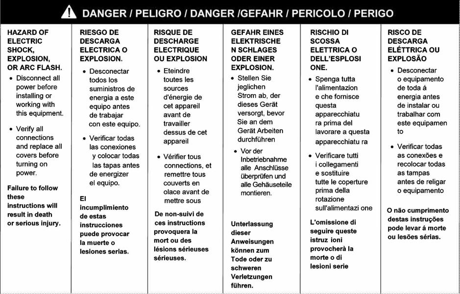
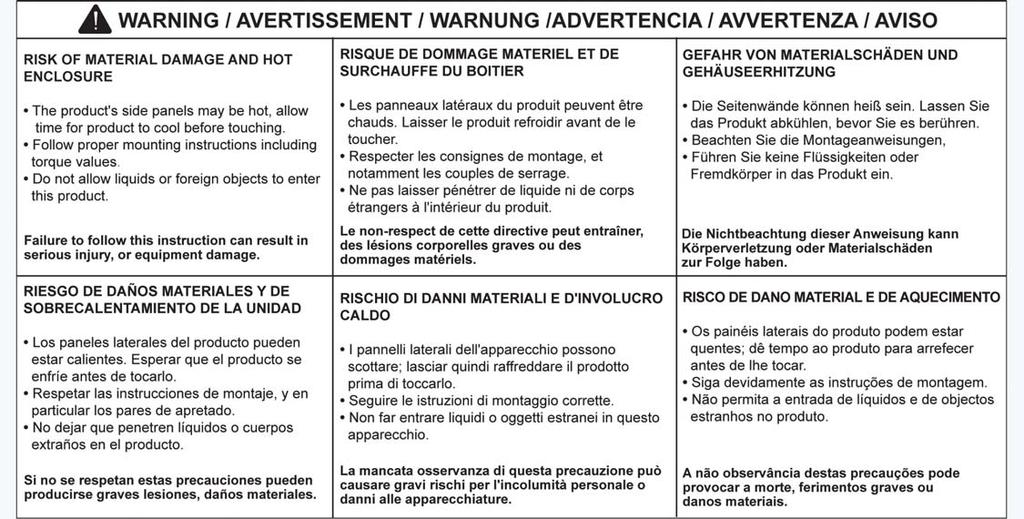
8 C1701 RELAY KIT SPECIAL CAUTIONARY NOTES When switching inductive loads such as pumps and motors, a transient diode may need to be installed between Load (+) and Ground. Please refer to the Crydom data sheet in Appendix A, and consult Campbell Scientific Canada if required. Applications where a device that is drawing a lot of current and have a long ON cycle require a heat-sink to prevent overheating. Please refer to the Crydom data sheet in Appendix A for details. 2. Installation 2.1 Wiring The C1701 has four connections that are wired to provide isolated switching of a load using a datalogger control port. The control port and datalogger ground are input to the relay and the load circuit is the relay output as shown below: Figure 1: Relay Wiring Diagram TABLE 1. Sensor Wiring Colour Pin Function CR10(X), CR510, 21X, CR7 CR23X Green 1 Output (-) Load (+) Load (+) Red 2 Output (+) Power Supply (+) Power Supply (+) Red 3 Input (+) Control Port Control Port Black 4 Input (-) G 2
9 C1701 RELAY KIT 2.2 Programming To activate the load circuit, the control port to which the relay is connected should be set to high (5V) using an appropriate datalogger program control instruction (eg. P86 or P92). To turn the load circuit off, toggle the control port low (0V) using a similar instruction. Be careful with your control logic, it is not good for many AC powered devices to be turned off/on too quickly. For this reason, users will often turn a device on and after it is turned off, not turn it on again for a set period of cool-down time. See the program example below. In this example, an irrigation pump is turned on for 10 minutes when the soil moisture goes below 10%. Then, it can not be turned on again for another 5 minutes. ;{CR10X} ; *Table 1 Program 01: 60 Execution Interval (seconds) ;If soil moisture goes to 10% or less, turn on irrigation pump for 10 minutes. 1: If Flag/Port (P91) 1: 12 Do if Flag 2 is High 2: 30 Then Do 2: Z=Z+1 (P32) 1: 2 Z Loc [ COUNTER1 ] 3: End (P95) 4: If (X<=>F) (P89) 1: 2 X Loc [ COUNTER1 ] 2: 3 >= 3: 300 F ; = 5 minutes 4: 30 Then Do 5: Z=F x 10^n (P30) ; Reset COUNTER1 to zero. 1: 0 F 2: 0 n, Exponent of 10 3: 2 Z Loc [ COUNTER1 ] 6: Do (P86) 1: 22 Set Flag 2 Low 7: End (P95) 8: If Flag/Port (P91) ; FLAG 2 prevents the pump from going on too soon 1: 22 Do if Flag 2 is Low 2: 30 Then Do ;If soil moisture goes too low, turn on an irrigation pump for 10 minutes. 9: If (X<=>F) (P89) 1: 1 X Loc [ SOIL_MOIS ] 2: 4 < 3: 10 F 4: 30 Then Do 3
10 C1701 RELAY KIT 10: Do (P86) 1: 41 Set Port 1 High 11: Do (P86) 1: 11 Set Flag 1 High 12: End (P95) 13: If Flag/Port (P91) 1: 11 Do if Flag 1 is High 2: 30 Then Do 14: Z=Z+1 (P32) 1: 3 Z Loc [ COUNTER2 ] ; adds 1 count per scan. 15: End (P95) ;If the pump was on for 10 minutes, turn it off. 16: If (X<=>F) (P89) 1: 3 X Loc [ COUNTER2 ] 2: 3 >= 3: 600 F ; = 10 minutes 4: 30 Then Do 17: Do (P86) ; Turn off pump 1: 51 Set Port 1 Low 18: Do (P86) ; Set FLAG #1 low 1: 21 Set Flag 1 Low 19: Do (P86) 1: 12 Set Flag 2 High 20: Z=F x 10^n (P30) ; Reset COUNTER2 to zero. 1: 0 F 2: 0 n, Exponent of 10 3: 3 Z Loc [ COUNTER2 ] 21: End (P95) 22: End (P95) 4
11 Appendix A
 Description 7A 12A 20A 40A 7A 12A")
12 Series 1-DC D1D to D5D series SSRs; MOSFET output Ratings from 7A to 200 VDC, and from 7A to 500 VDC DC Control Relays are easily paralleled for higher-current applications PRODUCT SELECTION Load Voltage 7A 10A 12A 20A 40A 100 VDC D1D07 D1D12 D1D20 D1D VDC D2D07 D2D12 D2D VDC D4D07 D4D VDC D5D07 D5D10 OUTPUT SPECIFICATIONS (1) Description 7A 12A 20A 40A 7A 12A 40A 7A 12A 7A 10A Operating Voltage Range Maximum Off-State Leakage Rated Voltage [marms] Maximum Load Current (3) [Adc] Minimum Load Current [ma] Maximum Surge Current (16.6ms) [Apk] Maximum On-State Voltage Rated Current [Vpk] Thermal Resistance Junction to Case (Rjc) [ C/W] Maximum On-State Resistance [RDS-ON][Ohms] INPUT SPECIFICATIONS (1) Description Control Voltage Range Minimum Turn-On Voltage Minimum Turn-Off Voltage Maximum Input Current (1-DC only) DC Control VDC 3.5 VDC 1.0 VDC 1.6 ma (5 VDC), 28 ma (32 VDC) Nominal Input Impedance See Note 4 Maximum Turn-On Time [µsec] 100 Maximum Turn-Off Time [msec] 1.0 GENERAL SPECIFICATIONS Description Parameters Dielectric Strength, Input/Output/Base (50/60Hz) 2500 VRMS Minimum Insulation Resistance (@ 500 V DC) 10 9 Ohm Maximum Capacitance, Input/Output 50 pf Ambient Operating Temperature Range -20 to 80 C Ambient Storage Temperature Range -20 to 125 C Weight (typical) 3.0 oz (86.5g) Encapsulation Thermally conductive Epoxy Terminals Screws and Saddle Clamps Furnished, Unmounted Recommended Terminal Screw Torque Range: 6-32 Screws - 10 in lbs and Screws -20 in. lbs. (Screws dry without grase) GENERAL NOTES 1) All parameters at 25 C and per section unless otherwise specified. 2) Dielectric strength and insulation resistance are measured between input and output 3) Heat sinking required, for derating curves see page 3. 4) Input circuitry version incorporates active current limiter.

13 MECHANICAL SPECIFICATIONS THERMAL DERATE INFORMATION
 Rev.")
14 WIRING DIAGRAM MAXIMUM SURGE VS DURATION AGENCY APPROVALS UL E (100 Volt Models 1-DC Only ) Rev
15
16 ANNEX - ENVIROMENTAL INFORMATION
VDIV10.1, VDIV2.1 Voltage Divider Terminal Input Modules
 VDIV10.1, VDIV2.1 Voltage Divider Terminal Input Modules Revision: 5/07 Copyright 1996-2007 Campbell Scientific, Inc. WARRANTY AND ASSISTANCE This equipment is warranted by CAMPBELL SCIENTIFIC (CANADA)
INSTRUCTION MANUAL. TC041-L Precipitation Sensor (Precipitation Occurrence & Rainfall Intensity) Sept 2008
 Sept 2008") INSTRUCTION MANUAL TC041-L Precipitation Sensor (Precipitation Occurrence & Rainfall Intensity) Sept 2008 Copyright 2008 Campbell Scientific (Canada)Corp. WARRANTY AND ASSISTANCE This equipment is warranted
INSTRUCTION MANUAL TC041-L Precipitation Sensor (Precipitation Occurrence & Rainfall Intensity) Sept 2008 Copyright 2008 Campbell Scientific (Canada)Corp. WARRANTY AND ASSISTANCE This equipment is warranted
INSTRUCTION MANUAL. HMP45C212 Temperature & Relative Humidity Probe. March Copyright 2007 Campbell Scientific (Canada)Corp.
Corp.") INSTRUCTION MANUAL HMP45C212 Temperature & Relative Humidity Probe March 2008 Copyright 2007 Campbell Scientific (Canada)Corp. WARRANTY AND ASSISTANCE The HMP45C212 TEMPERATURE AND RELATIVE HUMIDITY PROBE
INSTRUCTION MANUAL HMP45C212 Temperature & Relative Humidity Probe March 2008 Copyright 2007 Campbell Scientific (Canada)Corp. WARRANTY AND ASSISTANCE The HMP45C212 TEMPERATURE AND RELATIVE HUMIDITY PROBE
SAT SCD/ARGOS INSTRUCTION MANUAL
 INSTRUCTION MANUAL REVISION: 1/03 COPYRIGHT (c) 2000-2003 CAMPBELL SCIENTIFIC, INC. This is a blank page. WARRANTY AND ASSISTANCE This equipment is warranted by CAMPBELL SCIENTIFIC (CANADA) CORP. ( CSC
LI190SB QUANTUM SENSOR
 LI190SB QUANTUM SENSOR REVISION: 6/97 COPYRIGHT (c) 1982-1997 CAMPBELL SCIENTIFIC, INC. WARRANTY AND ASSISTANCE The LI190SB QUANTUM SENSOR is warranted by CAMPBELL SCIENTIFIC, INC. to be free from defects
CS105 BAROMETRIC PRESSURE SENSOR
 REVISION: 3/97 COPYRIGHT (c) 1995-1997 CAMPBELL SCIENTIFIC, INC. WARRANTY AND ASSISTANCE The CS105 BAROMETRIC PRESSURE SENSOR is warranted by CAMPBELL SCIENTIFIC, INC. to be free from defects in materials
DC1765 CELLULAR PHONE PACKAGE OPERATOR S MANUAL
 OPERATOR S MANUAL REVISION: 9/94 COPYRIGHT (c) 1987, 1994 CAMPBELL SCIENTIFIC, INC. WARRANTY AND ASSISTANCE The DC1765 CELLULAR PHONE PACKAGE is warranted by CAMPBELL SCIENTIFIC, INC. to be free from defects
CURS OHM CURRENT SHUNT TERMINAL INPUT MODULE INSTRUCTION MANUAL
 CURS100 100 OM CURRENT SUNT TERMNA NPUT MODUE NSTRUCTON MANUA REVSON: 4/00 COPYRGT (c) 1996 CAMPBE SCENTFC, NC. This is a blank page. Warranty and Assistance The CURS100 100 OM CURRENT SUNT TERMNA NPUT
Power-IO
 E Family of Solid State Relays Up to 900 VDC switched 12-20 khz, FAST switching times for superior PWM performance Ultra Cool Technology trademarked thermal management design Green LED that indicates input
SAT ARGOS INSTRUCTION MANUAL
 INSTRUCTION MANUAL 7/01 COPYRIGHT (c) 2000-2001 CAMPBELL SCIENTIFIC, INC. This is a blank page. Warranty and Assistance The is warranted by CAMPBELL SCIENTIFIC, INC. to be free from defects in materials
American Power Design, Inc.
 FEATURES 4 Customer Selects Output Voltage 4 Outputs to 28 Vdc 4 Wide Input Ranges (10-20Vdc, 18-36Vdc, 20-60Vdc, 36-72Vdc) 4 Excellent Line & Load Regulation 4 500 Vdc Output Isolation 4 Continuous Short
Instruction Manual Model M Switch, DPDT, Manual Select
 Instruction Manual Model 1582-70M Switch, DPDT, Manual Select November 2018 Rev 0 STATUS MODEL 1582 CROSS TECHNOLOGIES INC. MANUAL SELECT POWER Data, drawings, and other material contained herein are proprietary
American Power Design, Inc.
 FEATURES 4 Customer Selects Output Voltage 4 Outputs to 28 Vdc 4 Wide Input Ranges (10-20Vdc, 18-36Vdc, 20-60Vdc, 36-72Vdc) 4 Excellent Line & Load Regulation 4 Low Output Ripple 4 500 Vdc Output Isolation
SSR VL-12P-xC-NCS
 HELLROARING TECHNOLOGIES, INC. P.O. BOX 1521 POLSON, MT 59860 406 883-3801 HTTP://WWW.HELLROARING.COM SUPPORT@HELLROARING.COM SSR-40150-200VL-12P-xC-NCS The SSR-40150-200VL-12P-xC-NCS is designed for Low
SL300 Snow Depth Sensor USL300 SNOW DEPTH SENSOR. Revision User Manual
 USL300 SNOW DEPTH SENSOR Revision 1.1.2 User Manual 1 Table of Contents 1. Introduction... 3 2. Operation... 3 2.1. Electrostatic Transducer... 4 2.2. SL300 Analog Board... 4 2.3. SL300 Digital Circuit
Food Preparation Equipment Plastic Molding Lighting Control Dual Solid State Relays SEN Produkte, Support und Service TRONICAG
 THE GLOBAL EXPERT IN SOLID STATE RELAY TECHNOLOGY Food Preparation Equipment Plastic Molding Lighting Control rydom has a distinguished record of providing advanced, high quality products with timely delivery
SSR-150xxx-40VL-12P-xC-xxxCS
 HELLROARING TECHNOLOGIES, INC. P.O. BOX 1521 POLSON, MT 59860 406 883-3801 HTTP://WWW.HELLROARING.COM SUPPORT@HELLROARING.COM SSR-150xxx-40VL-12P-xC-xxxCS The SSR-150xxx-40VL-12P-xC-xxxCS is designed for
Preliminary Data Sheet!
 HELLROARING TECHNOLOGIES, INC. P.O. BOX 1521 POLSON, MT 59860 406 883-3801 HTTP://WWW.HELLROARING.COM SALES11@HELLROARING.COM SSD-100200-1200V-XP-XC Preliminary Data Sheet! The SSD-100200-1200V-XP-TTL
SSR V-12C. Industrial Switching Applications: Hellroaring Technologies, inc. P.O. Box 1521, Polson, Montana 59860
 !" SSR-4060-200V-12 The SSR-4060-200V-12 is designed for positive D load switching (solid state relay) applications for source voltages up to 120 Vdc (200V SSR output rating) and a control voltage input
3.6. Control Relays and Timers D A M D 2. Contents. Product Overview. Catalog Number Selection. Solid-State Relays
 .6 Control Relays and Timers Product Overview Catalog Number Selection D9, D96 and D99 Series Description D9 = Hockey puck D96 = Compact D99 = DIN rail Contents D 9 2 5 A M D 2 Output Voltage 1 = 2 60
Digital Lighting Systems, Inc.
 PD408-AN0-277 ANALOG 0-0 V 0-0V analog control 4 Channel x 2250 W Dimmer & Switch Packs 220/240/277 Volts operation PD408-AN0-277 4 circuit Analog -0V 4 x 8 A. Dimmer pack Serial Number Digital Lighting
American Power Design, Inc.
 FEATURES 4 Customer Selects Output Voltage 4 Outputs to 1000 Vdc 4 Fully Programable Outputs 4 Single and Dual Outputs 4 Wide Input Ranges (10-20Vdc, 18-36Vdc) 4 1000 Vdc Output Isolation 4 Continuous
INSTRUCTION MANUAL MODEL 2455T SUBCARRIER MODULATOR
 INSTRUCTION MANUAL MODEL 2455T SUBCARRIER MODULATOR Data, drawings, and other material contained herein are proprietary to Cross Technologies, Inc., and may not be reproduced or duplicated in any form
NR-LITE NET RADIOMETER INSTRUCTION MANUAL
 NR-LITE NET RADIOMETER INSTRUCTION MANUAL REVISION: 5/02 COPYRIGHT (c) 1998-2002 CAMPBELL SCIENTIFIC, INC. This is a blank page. Warranty and Assistance The NR-LITE NET RADIOMETER is warranted by CAMPBELL
American Power Design, Inc.
 , Inc. FEATURES 4 Customer Selects Output Voltage 4 Ultra Wide Input Ranges (936Vdc, 2060Vdc) 4 Efficiency 89% (typ.) 4 Independently Isolated Outputs 4 SixSided Shielded Case 4 Remote On/Off Control 4
P.O. BOX 1521 POLSON, MT SSR V-12C
 HELLRORING TEHNOLOGIES, IN. P.O. OX 1521 POLSON, MT 59860 406 883-3801 HTTP://WWW.HELLRORING.OM SUPPORT@HELLRORING.OM SSR-15275-30V-12 The SSR-15275-30V-12 is designed for positive D load switching (solid
American Power Design, Inc.
 FEATURES 4 Customer Selects Output Voltage 4 Outputs to 1000 Vdc 4 Low Profile 4 Single and Dual Outputs 4 Ultra Wide Input Ranges (9-36Vdc, 20-60Vdc, 36-72Vdc) 4 1000 Vdc Output Isolation 4 Continuous
7I25 H-BRIDGE MANUAL
 7I25 H-BRIDGE MANUAL VERSION 1.0 Copyright 2002 by MESA ELECTRONICS Richmond, CA. Printed in the United States of America. All rights reserved. This document and the data disclosed herein is not to be
HELLROARING TECHNOLOGIES, INC. P.O. BOX 1521 POLSON, MT
 HELLRORING TEHNOLOGIES, IN. P.O. OX 1521 POLSON, MT 59860 406 883-3801 HTTP://WWW.HELLRORING.OM SLES12@HELLRORING.OM SSR-15240-60V-xx The SSR-15240-60V-xx are designed for positive D load switching (solid
Process Calibrator. TechChek 820
 Process Calibrator TechChek 80 CONTENTS GENERAL... TURN ON... CONNECTIONS... TILT STAND...4 CHANGING BATTERIES...4 RESTORING DEFAULT SETTINGS... CONFIGURING TEMPERATURE SCALES... ENABLING AUTO-OFF... SELECTING
Broadband Step-Up Transformer. User Manual
 Broadband Step-Up Transformer User Manual 990-1930 09/2004 Introduction Introduction About this unit The APC Step-Up Transformer provides 220 V power from 60 VAC Broadband cable systems. Safety Electrical
TRANSDUCER IN-LINE AMPLIFIER
 TRANSDUCER IN-LINE Voltage Model AMPLIFIER 2080 Arlingate, Columbus, Ohio 43228, (614) 850-5000 Sensotec, Inc. 2080 Arlingate Lane Columbus, Ohio 43228 Copyright 1995 by Sensotec, Inc. all rights reserved
TRANSDUCER IN-LINE AMPLIFIER
 TRANSDUCER IN-LINE Bi-Polar Model AMPLIFIER 2080 Arlingate Lane, Columbus, Ohio 43228 (614) 850-5000 Sensotec, Inc. 2080 Arlingate Lane Columbus, Ohio 43228 Copyright 1995 by Sensotec, Inc. all rights
C5000 & C5000NF PULSE INITIATOR. Introduction
 C142-05, Page 1 952-361-3026, INC. (Fax) 952-368-4129 327 LAKE HAZELTINE DRIVE, CHASKA, MN 55318 800-328-0738 C5000 & C5000NF PULSE INITIATOR Introduction The MAXIGARD C5000 and C5000NF are designed to
Vi6208, Vi6216, Vi6232 Vi6308, Vi6316, Vi6332
 MODELs Vi6208, Vi6216, Vi6232 Vi6308, Vi6316, Vi6332 Automatic Video Compensation UTP Receiver Hubs User s Manual 7810 Trade Street, Suite 100 San Diego, CA 92121, U.S.A. Phone: (858) 484-5209 Fax: (858)
INSTRUCTION MANUAL , 05106, and R.M. Young Wind Monitors. Revision: 7/05. Copyright (c) Campbell Scientific, Inc.
 Campbell Scientific, Inc.") INSTRUCTION MANUAL 05103, 05106, and 05305 R.M. Young Wind Monitors Revision: 7/05 Copyright (c) 1984-2005 Campbell Scientific, Inc. Warranty and Assistance The 05103, 05106, AND 05305 R.M. YOUNG WIND
INSTRUCTION MANUAL 05103, 05106, and 05305 R.M. Young Wind Monitors Revision: 7/05 Copyright (c) 1984-2005 Campbell Scientific, Inc. Warranty and Assistance The 05103, 05106, AND 05305 R.M. YOUNG WIND
Ordering Information. Stepping Relay Unit G9B. Model Number Legend
 Stepping Relay Unit CSM DS_E_4_1 Ideal for Controlling Pumps and Production Lines with Six or Twelve Stepping Circuits Built-in relays switch 2 A at 250 VAC or 30 VDC. Initialization of stepping with reset
AM32 MULTIPLEXER INSTRUCTION MANUAL
 INSTRUCTION MANUAL REVISION: 2/96 COPYRIGHT (c) 1983-1996 CAMPBELL SCIENTIFIC, INC. This is a blank page. WARRANTY AND ASSISTANCE The AM32 MULTIPLEXER is warranted by CAMPBELL SCIENTIFIC, INC. to be free
BC145 SIGNAL ISOLATOR BOARD
 BC145 SIGNAL ISOLATOR BOARD 4/17 Installation & Operating Manual MN1373 Any trademarks used in this manual are the property of their respective owners. Important: Be sure to check www.baldor.com to download
MINI 048 / JUN 2003 PAGE 1. Temperature I/O Module HE500OCS048 / HE500OCS078 HE500RCS078
 MINI 048 / 078 07 JUN 2003 PAGE 1 Temperature I/O Module HE500OCS048 / HE500OCS078 HE500RCS078 Mini OCS/RCS 1 SPECIFICATIONS Relay Outputs Number of Channels 2 N.O. Relays Maximum Load Current (resistive)
1523, 1524 Thermometer Readout User s Guide
 1523, 1524 Thermometer Readout User s Guide ThermoWorks Inc. 1762 W. 20 S. #100 Lindon, UT 84042 Phone: 801.756.7705 Fax: 801.756.8948 Email: info@thermoworks.com Web: www.thermoworks.com Rev. 891001_EN
10 Amp Digital PWM Motor Speed Controller CV-2110-HD and CV-2110-HDS
 10 Amp Digital PWM Motor Speed Controller CV-2110-HD and CV-2110-HDS The Analog / Digital PWM controller allows you to control the speed of a motor, brightness of a lamp or other device using an analog
User s Guide. 400A AC/DC Clamp Meter. Model MA220
 User s Guide 400A AC/DC Clamp Meter Model MA220 Introduction Thank you for selecting the Extech MA200 AC/DC Clamp Meter. This meter measures AC/DC Current, AC/DC Voltage, Resistance, Capacitance, Frequency,
EXECUTE Shiloh Road Alpharetta, Georgia (770) FAX (770) Toll Free
 FAX (770) Toll Free") Instruction Manual Model 1586-06 RF Attenuator May 2009 Rev A 1 2 3 12.5 53.5 16.3 MODEL 1586 RF ATTENUATOR CROSS TECHNOLOGIES INC. EXECUTE PS1 PS2 Data, drawings, and other material contained herein are
Instruction Manual Model 1586-06 RF Attenuator May 2009 Rev A 1 2 3 12.5 53.5 16.3 MODEL 1586 RF ATTENUATOR CROSS TECHNOLOGIES INC. EXECUTE PS1 PS2 Data, drawings, and other material contained herein are
MBC Bipolar Microstep Driver. User s Guide E. Landon Drive Anaheim, CA
 MBC10641 Bipolar Microstep Driver User s Guide A N A H E I M A U T O M A T I O N 4985 E. Landon Drive Anaheim, CA 92807 e-mail: info@anaheimautomation.com (714) 992-6990 fax: (714) 992-0471 website: www.anaheimautomation.com
INSTRUCTION MANUAL MODEL 2779 SUBCARRIER MODULATOR
 INSTRUCTION MANUAL MODEL 2779 SUBCARRIER MODULATOR Data, drawings, and other material contained herein are proprietary to Cross Technologies, Inc., and may not be reproduced or duplicated in any form without
MLA High Performance Microstepping Driver. User s Guide E. Landon Drive Anaheim, CA
 MLA10641 High Performance Microstepping Driver User s Guide A N A H E I M A U T O M A T I O N 4985 E. Landon Drive Anaheim, CA 92807 e-mail: info@anaheimautomation.com (714) 992-6990 fax: (714) 992-0471
Model 1791 VHF Radio User's Manual
 Model 79 VHF Radio User's Manual ALL WEATHER INC 65 NATIONAL DRIVE SACRAMENTO, CA 95834 WWW.ALWEATHERINC.COM 79 VHF RADIO USER'S MANUAL CONTENTS INTRODUCTION... Description... Transmitter Module... Power
15 Amp Digital High Frequency PWM Motor Speed Controller SPD-315-D and SPD-315-DS
 15 Amp Digital High Frequency PWM Motor Speed Controller SPD-315-D and SPD-315-DS The SPD-315-D(S) PWM controller allows you to control the speed of a motor, brightness of a lamp or other load using a
An American Control Electronics Brand PCM4 SERIES USER MANUAL PCM4.
 An American Control Electronics Brand PCM4 SERIES PCM4 USER MANUAL www.minarikdrives.com Dear Valued Consumer: Congratulations on your purchase of the PCM4 Series isolation card. This User Manual was created
INSTRUCTION MANUAL. Model Autoranging DMM ProbeMeter TM. Measures voltage, resistance, frequency, capacitance, temperature, and duty cycle.
 INSTRUCTION MANUAL Model 403380 Autoranging DMM ProbeMeter TM Measures voltage, resistance, frequency, capacitance, temperature, and duty cycle. Back lit LCD with Autorange and full function displays Audible
BCM Array TM BC384R120T030VM-00
 BCM Array TM BC384R120T030VM-00 Features 384 V to 12 V VI BRICK BCM Array 300 Watt (450 Watt for 1 ms) Vertical mount package reduces footprint Integrated heat sink simplifies thermal management ZVS /
Model 935A. Dual Tone Sender INSTRUCTION MANUAL
 Model 935A Dual Tone Sender INSTRUCTION MANUAL Monroe Electronics 100 Housel Ave Lyndonville NY 14098 800-821-6001 585-765-2254 fax 585-765-9330 monroe-electronics.com Printed in USA Copyright Monroe Electronics,
Series HD 2A, 60Vdc, True Output Status Feedback, Short-Circuit Protected DC Solid-State Relay
 Part* Number HD00CFW DESC Drawing Number HD00CFY 88062-008 HD02CFW HD02CFY 88062-006 HD20CFW HD20CFY 88062-004 HD22CFW HD22CFY 88062-002 HD24CFW HD24CFY Relay Description Solid State Relay (SSR) SSR with
JMAA-3600HR16-UL. Installation and Operation Instructions. Performance Series 360w RMS 4-Channel Amplifier Kit For Harley RoadGlide Ultra
 Performance Series 360w RMS 4-Channel Amplifier Kit For 2016-2018 Harley RoadGlide Ultra # JMAA-3600HR16-UL 2017 J&M Corporation. All rights reserved. 9/17 Installation and Operation Instructions Product
The Global Expert in Solid State Switching Technology. Panel Mount Solid State Relays Vol. II
 The Global Expert in Solid State Switching Technology Panel Mount Solid State Relays Vol. II Crydom, a brand of Custom Sensors & Technologies (CST) and global expert in Solid State Relay Technology, has
JMAA-1800HR15. Installation and Operation Instructions. 180w Performance Series Amplifier Kit For Harley RoadGlide/ Ultra
 180w Performance Series Amplifier Kit For 2015-2018 Harley RoadGlide/ Ultra # JMAA-1800HR15 2017 J&M Corporation. All rights reserved. 9/17 Installation and Operation Instructions Product Description This
Angular Rate Sensor. Owner's Manual
 Angular Rate Sensor Owner's Manual Part Number: ARS-C132-1A WATSON INDUSTRIES, INC. 3041 MELBY ROAD EAU CLAIRE, WI 54703 Phone: (715) 839-0628 FAX: (715) 839-8248 email: support@watson-gyro.com 1 Table
AMP-13 OPERATOR S MANUAL
 AMP-13 OPERATOR S MANUAL Version 2.0 Copyright 2008 by Vatell Corporation Vatell Corporation P.O. Box 66 Christiansburg, VA 24068 Phone: (540) 961-3576 Fax: (540) 953-3010 WARNING: Read instructions carefully
Earth Fault Indicator EFI-BLZ-50 User Manual
 Earth Fault Indicator EFI-BLZ-50 User Manual CONTENTS SAFETY NOTICE.................................................................................... 3 1 OVERVIEW......................................................................................
Series 500. Owner s Manual. Analog Transmitters by Data Industrial. Data Industrial. Data Industrial 2/95 PN 72806
 Series 500 Analog Transmitters by Data Industrial Data Industrial Owner s Manual Data Industrial 2/95 PN 72806 Table of Contents Introduction... 1 4-20 ma Loop Supply Requirements... 2 Installation...
MODEL DDS8par 48-bit Binary Parallel Controlled Synthesizer
 DDS8par Manual Addendum 1/7 MODEL DDS8par 48-bit Binary Parallel Controlled Synthesizer This is a manual addendum to the Novatech Instruments, Inc. Model DDS8m. This addendum covers the changes made for
o-ring grease can be used to hold the o-ring in the groove during installation.
 42G1215A-XT-1-2 and 42G1215A-XT-1-3 ANTENNA GUIDE OM-20000154 Rev 1 December 2013 The 42G1215A-XT-1-3 and 42G1215A-XT-1-2 are active antennas designed to operate at the GPS L1 and L2 frequencies, 1575.42
User s Guide Instructions for Installation and Operation
 User s Guide Instructions for Installation and Operation This page intentionally left blank. 2.4 GHZ SPREAD SPECTRUM REMOTE CONTROLS Handheld Transmitter Model KTXW24SSA1 KTXW24SSA2 KTXW24SSA4 KTXW24SSA6
Amplified High Speed Photodetectors
 Amplified High Speed Photodetectors User Guide 3340 Parkland Ct. Traverse City, MI 49686 USA Page 1 of 6 Thank you for purchasing your Amplified High Speed Photodetector from EOT. This user guide will
SDM-IO16 16 CHANNEL INPUT/OUTPUT EXPANSION MODULE INSTRUCTION MANUAL
 SDM-IO16 16 CHANNEL INPUT/OUTPUT EXPANSION MODULE INSTRUCTION MANUAL REVISION: 2/03 COPYRIGHT (c) 2002-2003 CAMPBELL SCIENTIFIC, INC. This is a blank page. Warranty and Assistance The SDM-IO16 16 CHANNEL
Models Tension/Compression Pancake Load Cell Model 3174 with tension base DESCRIPTION FEATURES
 Models 3174-3176 Model 3174 Model 3174 with tension base DESCRIPTION Models 3174, 3175, and 3176 are fatigue-resistant, low-profile tension and compression load cells that are well suited to materials
SDM-CVO4 4-CHANNEL CURRENT/VOLTAGE OUTPUT MODULE INSTRUCTION MANUAL
 SDM-CVO4 4-CHANNEL CURRENT/VOLTAGE OUTPUT MODULE INSTRUCTION MANUAL REVISION: 1/03 COPYRIGHT (c) 2001-2003 CAMPBELL SCIENTIFIC, INC. This is a blank page. Warranty and Assistance The SDM-CVO4 4-CHANNEL
American Power Design, Inc.
 FEATURES 4 Customer Selects Output Voltage 4 Fully Regulated Outputs to + or - 8000 Vdc 4 0-100% Programable Output 4 High Stability (
2001A. 200KHz Function Generator Instruction Manual. 99 Washington Street Melrose, MA Phone Toll Free
 2001A 200KHz Function Generator Instruction Manual 99 Washington Street Melrose, MA 02176 Phone 781-665-1400 Toll Free 1-800-517-8431 Visit us at www.testequipmentdepot.com WARRANTY Global Specialties
SI-125 Power Amplifier Manual 6205 Kestrel Road; Mississauga, Ontario; Canada; L5T 2A1 November 2016, Rev 0.5
 SI-125 Power Amplifier Manual 6205 Kestrel Road; Mississauga, Ontario; Canada; L5T 2A1 November 2016, Rev 0.5 Phone: (905) 564-0801 Fax: (905) 564-0806 www.telecor.com E:\T2-108\T2-M108-ABC\T2-M108-B.doc/AD
User s Manual. MiniTec TM Series. Model MN26 (Model MN26T includes temperature probe) Mini Autoranging MultiMeter
 Mini Autoranging MultiMeter") User s Manual MiniTec TM Series Model MN26 (Model MN26T includes temperature probe) Mini Autoranging MultiMeter Introduction Congratulations on your purchase of Extech s MN26 Autoranging Multimeter. This
User s Manual MiniTec TM Series Model MN26 (Model MN26T includes temperature probe) Mini Autoranging MultiMeter Introduction Congratulations on your purchase of Extech s MN26 Autoranging Multimeter. This
User s Guide Instructions for Installation and Operation
 User s Guide Instructions for Installation and Operation 2.4 GHZ SPREAD SPECTRUM REMOTE CONTROLS Keyfob Transmitters Models KTX24SS1 KTXW24SS3 KTX24SS2 KTX24SS3 Wall Mount Models NTX24SS1 NTX24SS2 Remote
R-X SERIES. Decade Resistor
 PRECISION INSTRUMENTS FOR TEST AND MEASUREMENT R-X SERIES Decade Resistor User and Service Manual Effectivity: Serial Numbers beginning with P2 RX im/august, 2002 Copyright 2002 IET Labs, Inc. IET LABS,
CCE Image may differ from the actual product By Martin Labbé, eng., Jasmin Goupil & Louis Perreault
 CCE-32 1.09 Image may differ from the actual product By Martin Labbé, eng., Jasmin Goupil & Louis Perreault Index 1. General description... 5 2. Applications... 5 3. Installation... 5 4. Connections...
BLD75-1. Bilevel Step Motor Driver. User s Guide. #L010125
 BLD75-1 Bilevel Step Motor Driver User s Guide A N A H E I M A U T O M A T I O N #L010125 1 Features Unipolar Operation 10 Amps per Phase Operating Current (Kick Current) 7 Amps per Phase Standstill Current
XPR522 XPR540. XPR SERIES INSTALLATION / OWNER'S MANUAL Mobile Power Amplifiers
 XPR522 XPR540 XPR SERIES INSTALLATION / OWNER'S MANUAL Mobile Power Amplifiers Preparation Please read entire manual before installation. Due to the technical nature of amplifiers, it is highly recommended
Performance Series 360w Amplifier Kit For Harley RoadGlide with Lower/Rear Speakers JMAA-3600HR15-RC
 Performance Series 360w Amplifier Kit For 2015-2018 Harley RoadGlide with Lower/Rear s # JMAA-3600HR15-RC 2017 J&M Corporation. All rights reserved. 9/17 Installation and Operation Instructions Product
MODEL UBP-10 UNIVERSAL IN-LINE TRANSDUCER AMPLIFIER BI-POLAR SUPPLY, 0-10 VOLT OUTPUT
 MODEL UBP-10 UNIVERSAL IN-LINE TRANSDUCER AMPLIFIER BI-POLAR SUPPLY, 0-10 VOLT OUTPUT 2080 Arlingate Lane, Columbus, Ohio 43228 (614) 850-5000 Sensotec, Inc. 2080 Arlingate Lane Columbus, Ohio 43228 Copyright
Instruction Manual Model Upconverter
 Instruction Manual Model 2006-01 Upconverter October 2013, Rev. B IF IN RF OUT Data, drawings, and other material contained herein are proprietary to Cross Technologies, Inc., but may be reproduced or
WORLD-BEAM QS18AFF200 Sensors with Foreground Suppression
 WORLD-BEAM QS8AFF00 Sensors with Foreground Suppression Datasheet Compact sensors featuring extended range and foreground suppression mode Exceptional optical performance; up to 00 mm sensing range in
Active CCTV Receiver Balun Installation Guide
 Active CCTV Receiver Balun 500015 Installation Guide P/N: 94-000304-C SE-000266-C Copyright Notice: Copyright 2009 MuxLab Inc. All rights reserved. Printed in Canada. No part of this publication may be
MDC V, 2A Brushless Controller. User s Guide E. Landon Drive Anaheim, CA
 MDC010-024031 24V, 2A Brushless Controller User s Guide A N A H E I M A U T O M A T I O N 4985 E. Landon Drive Anaheim, CA 92807 e-mail: info@anaheimautomation.com (714) 992-6990 fax: (714) 992-0471 website:
PA Watt Compact Two Zone Amplifier to Drive up to 60 Paging Speakers. 60 Watt / 2 Zone Power Amplifier. Features. Applications.
 Designed, Manufactured and Supported in the USA PRODUCT MANUAL COMMUNICATION & SECURITY SOLUTIONS PA-60 60 Watt / 2 Zone Power Amplifier April 25, 2013 60 Watt Compact Two Zone Amplifier to Drive up to
DA6002D-DA10004D. INSTALLATION / OWNER'S MANUAL Mobile Power Amplifiers
 DA6002D-DA10004D INSTALLATION / OWNER'S MANUAL Mobile Power Amplifiers Preparation Please read entire manual before installation. Due to the technical nature of amplifiers, it is highly recommended that
Programmable K-Factor Scaler B and Programming Software Kit B
 Programmable K-Factor Scaler B220-885 and Programming Software Kit B220-900 INSTALLATION & INSTRUCTION MANUAL 8635 Washington Avenue Racine, Wisconsin 53406 Toll Free: 800.235.1638 Phone: 262.639.6770
VTM VTM TM Transformer
 VTM VTM TM Transformer V048F480T006 V048F480M006 48 V to 48 V V I Chip TM Converter 6.3 A (9.4 A for 1 ms) High density 1017 W/in 3 Small footprint 260 W/in 2 Low weight 0.5 oz (15 g) Pick & Place / SMD
200Amp AC Clamp Meter + NCV Model MA250
 User's Guide 200Amp AC Clamp Meter + NCV Model MA250 Introduction Congratulations on your purchase of this Extech MA250 Clamp Meter. This meter measures AC Current, AC/DC Voltage, Resistance, Capacitance,
INSTALLATION GUIDE ET1551U. IP Video Camera Over Single Twisted Wire Ethernet Extender with EtherStretch. Description
 INSTALLATION GUIDE ET1551U IP Video Camera Over Single Twisted Wire Ethernet Extender with EtherStretch Description The ET1551U is another component of the NITEK EtherStretch line. This Environmentally
INSTALLATION GUIDE. Video Balun Transceiver with fixed BNC for twisted pair operation with other balun transceivers or active receivers.
 INSTALLATION GUIDE VB37M Video Balun Transceiver for Twisted Pair Description Video Balun Transceiver with fixed BNC for twisted pair operation with other balun transceivers or active receivers. The VB37M
User s Guide FLSC-45/45B. Paddlewheel Signal Conditioner. Shop online at omega.com
 TM User s Guide Shop online at omega.com e-mail: info@omega.com For latest product manuals: www.omegamanual.info NORWALK, CT FLSC-45/45B Paddlewheel Signal Conditioner omega.com info@omega.com U.S.A. Headquarters:
Ordering Information. Ratchet Relay G4Q. Plug-in Models. Model Number Legend
 Ratchet Relay CSM OEE_DS_E_1_1 Unique Ratchet Mechanism Assures Positive Alternate Transfer/Switching Operation Each contact in the double-pole contact mechanism performs alternate make-brake operation
Opus 21 s80 Integrated Amplifier Owner's Manual
 Opus 21 s80 Integrated Amplifier Owner's Manual r e s o l u t i o n From all of us at Resolution Audio, thank you for choosing the Opus 21 s80 amplifier. We went to great lengths to design and produce
Broadband Current Probe Series Operation Manual
 Broadband Current Probe Series Operation Manual 1 TABLE OF CONTENTS INTRODUCTION 3 GENERAL INFORMATION 4 OPERATING INSTRUCTIONS 5 FORMULAS 6 MAINTENANCE 7 WARRANTY 8 2 INTRODUCTION CURRENT PROBE SPECIFICATIONS
409DMQ... Series SCHOTTKY RECTIFIER. 400 Amp. Bulletin PD rev. B 10/02. Description/ Features. Major Ratings and Characteristics
 Bulletin PD-20724 rev. B 0/02 409DMQ... Series SCHOTTKY RECTIFIER 400 Amp TO-244AB isolated doubler Major Ratings and Characteristics Characteristics 409DMQ... Units I F(AV) Rectangular 400 A waveform
Ultra Fast NPT - IGBT
 APT8GR12JD 12V, 8A, V ce(on) = 2.V Typical Features Ultra Fast NPT - IGBT The Ultra Fast NPT - IGBT family of products is the newest generation of planar IGBTs optimized for outstanding ruggedness and
DA560D COMPACT SERIES. INSTALLATION / OWNER'S MANUAL Mobile Power Amplifiers
 DA560D COMPACT SERIES INSTALLATION / OWNER'S MANUAL Mobile Power Amplifiers Preparation Please read entire manual before installation. Due to the technical nature of amplifiers, it is highly recommended
Quick Start Guide. ELPRO 905U-L-T Wireless I/O Transmitter Unit. man_905u-l-t_quickstart_v1.9.doc
 Quick Start Guide ELPRO 905U-L-T Wireless I/O Transmitter Unit man_905u-l-t_quickstart_v1.9.doc About this document This document is the and contains the following sections: Section Basic steps for using
POWER LINE IMPEDANCE STABLIZATION NETWORK (LISN) MODEL PLISN-25/2. 5 khz 1 GHz
 MODEL PLISN-25/2. 5 khz 1 GHz") INSTRUCTION MANUAL POWER LINE IMPEDANCE STABLIZATION NETWORK (LISN) MODEL PLISN-25/2 5 khz 1 GHz INSTRUCTION MANUAL THIS INSTRUCTION MANUAL AND ITS ASSOCIATED INFORMATION IS PRO- PRIETARY. UNAUTHORIZED
INSTRUCTION MANUAL POWER LINE IMPEDANCE STABLIZATION NETWORK (LISN) MODEL PLISN-25/2 5 khz 1 GHz INSTRUCTION MANUAL THIS INSTRUCTION MANUAL AND ITS ASSOCIATED INFORMATION IS PRO- PRIETARY. UNAUTHORIZED
G7K. Latching Relay. Compact Mechanical Lock Latching Relays with Manual Buttons. Model Number Structure. Ordering Information
 Latching Relay CSM DS_E Compact Mechanical Lock Latching Relays with Manual Buttons Compact design with a height of 7 mm, width of. mm, and depth of 8. mm. Plus, one Relay only weighs 7 g. Quick set and