Amplified High Speed Photodetectors
|
|
|
- Corey Perkins
- 5 years ago
- Views:
Transcription


1 Amplified High Speed Photodetectors User Guide 3340 Parkland Ct. Traverse City, MI USA Page 1 of 6
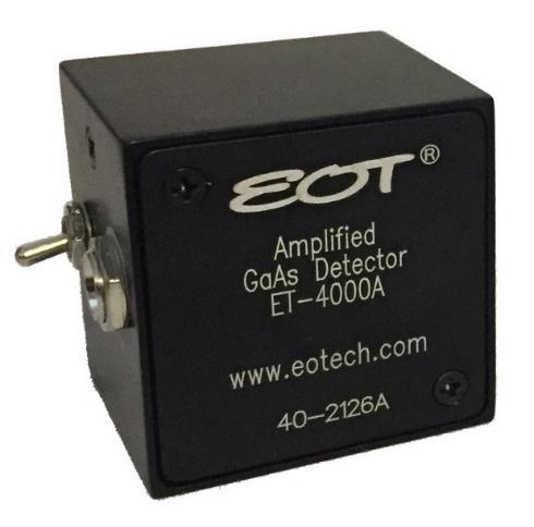
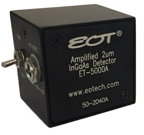
2 Thank you for purchasing your Amplified High Speed Photodetector from EOT. This user guide will help answer any questions you may have regarding the safe use and optimal operation of your Photodetector. TABLE OF CONTENTS I. Amplified High Speed Photodetector Overview... 2 II. Operation of your EOT Amplified High Speed Photodetector... 3 III. Troubleshooting... 3 IV. Schematics: Amplified Photodetectors... 4 V. Warranty Statement and Repair... 4 VI. Glossary of Terms... 5 I. Amplified High Speed Photodetector Overview EOT s Amplified Photodetectors contain PIN photodiodes that utilize the photovoltaic effect to convert optical power into an electrical current and a fixed gain transimpedance amplifier allowing measurement of <1 mw input powers. Figure 1 below identifies the main elements of your Amplified High Speed Photodetector. Figure 1: EOT Amplified High Speed Photodetector Power Switch Power Jack DC Monitor Output (SMA) Sensor Aperture Signal Output (SMA) When terminated into 50 Ω into an oscilloscope, the pulsewidth of a laser can be measured. When terminated into a spectrum analyzer, the frequency response of a laser can be measured Parkland Ct. Traverse City, MI USA Page 2 of 6
3 II. Operation of your EOT Amplified High Speed Photodetector A. Caution: Eye safety precautions must be followed when utilizing any equipment used in the vicinity of laser beams. Laser beams may reflect from the surface of the detector or the optical mount and caution must be exercised. B. Mount the detector to an optical stand by the mounting holes on the bottom of the detector housing. C. Adjust the voltage of the oscilloscope to 20 mv/division before connecting the detector. D. Connect the detector to the oscilloscope using a coaxial cable designed for 10 GHz operation. The DC Monitor cable can be a general purpose cable. E. Use the 50 Ω termination input of the oscilloscope. F. Connect the DC Monitor to a high impedance device such as a multimeter. Set the device to millivolts or volts. The output of the DC Monitor converts the average photodiode current to a voltage output of 1 mv/ua. The DC Monitor output has an offset voltage of less than 70 mv. G. Note that the external power supply is a 5 VDC regulated supply with a positive center pin. Using a supply other than 5 VDC could damage the detector. H. After being certain that the damage threshold of the detector is not exceeded, place the detector in the center of the laser beam. I. Align the detector for the desired output using either the signal output or the DC Monitor (Note: the signal output is AC coupled). If a CW laser is used for beam alignment, the DC Monitor output should be used. III. Troubleshooting A. No signal is seen the first time the detector is used. 1. Is the power switch on? Is the external power supply connected? 2. Is your signal a CW signal? If so, there will not be a signal output present because the detector is AC coupled. There would be an output from the DC Monitor. 3. Be certain that the signal is not high off scale on the oscilloscope. 4. Is the wavelength of the laser within the spectral range of the detector? 5. Has a 50 Ω termination input been used? 3340 Parkland Ct. Traverse City, MI USA Page 3 of 6


4 6. Try moving the detector within the laser beam. 7. Is there enough light incident on the detector to generate a signal? The detector s small active area makes alignment somewhat difficult. B. A signal has been previously obtained, but not currently. 1. Try steps listed under A. 2. Inspect the active area of the photodiode for any signs of damage. 3. Recheck if the voltage is preset at the external power supply plug. C. Increasing the power incident on the detector does not result in a higher voltage signal on the oscilloscope. 1. The detector is probably saturated. You should lower the power incident on the detector to a level below the saturation point. IV. Schematics: Amplified Photodetectors SMA Connector V. Warranty Statement and Repair EOT warrants its products to be free from defects in material and workmanship and complies with all specifications. EOT will at its option, repair or replace any product or component found to be defective during the warranty period. This warranty applies only to the original purchaser and is not transferrable for a period of one year after date of original shipment. The foregoing warranties shall not apply, and EOT reserves the right to refuse warranty service, should malfunction or failure result from: a. Damage caused by improper installation, handling or use. b. Unauthorized product modification or repair. c. Operation outside the environmental or damage specifications of the product. d. Contamination not reported to EOT within 30 days of the original ship date Parkland Ct. Traverse City, MI USA Page 4 of 6
5 e. EOT s output isolators contain a spacer at the end of the isolator. Under certain conditions, an off-axis back-reflection from the workpiece could focus down onto the output displacer or polarizer inside the isolator. The purpose of the spacer is to eliminate the conditions under which this could happen. Should EOT s output isolators be purchased without the spacer, or should the spacer be removed, damage to the output displacer or polarizer will not be covered under warranty and the customer will be responsible for all costs associated with such an occurrence. This warranty is exclusive in lieu of all other warranties whether written, oral, or implied. EOT specifically disclaims the implied warranties of merchantability and fitness for a particular purpose. In no event shall EOT be liable for an indirect, incidental, or consequential damages in connection with its products. If the customer believes there is a problem with the photodetector, they should immediately contact EOT s Sales/Customer department at or customerservice@eotech.com. EOT s Customer Service department will either issue an RMA for the device, or provide the customer with a procedure and authorize the customer to modify the device. All returns should reference the RMA number on the outside of the shipping container and should be sent to: Attn: Sales/Customer Service 3340 Parkland Ct. Traverse City, MI USA EOT reserves the right to inspect photodetectors returned under warranty to assess if the problem was caused by a manufacturer defect. If EOT determines the problem is not due to a manufacturer defect, repairs will be done at the customer s expense. EOT will always provide a written quote for repair prior to performing repairs at the customer s expense. VI. Glossary of Terms Amplifier: Provides a transimpedance gain throughout the photodiode s bandwidth. The photodiode current is converted to an output voltage. Bandwidth: Unlike non-amplified photodetector bandwidth, which is defined as the range of frequencies from 0 Hz (DC) to the frequency at which the amplitude decreases by 3dB, the amplified photodetectors have a low frequency cutoff of -3 db, which is greater than 0Hz due to the DC Block Capacitor. Bandwidth and rise time can be approximately related by the equation: Bandwidth 0.35/rise time for a Gaussian pulse input. Bias Voltage: The photodiode s junction capacitance can be modified by applying a reverse voltage. The bias voltage reduces the junction capacitance, which causes the photodiode to have a faster response Parkland Ct. Traverse City, MI USA Page 5 of 6
6 Conversion Gain: The relative level of the optical input power that is amplified and converted into a voltage output. DC Block Capacitor: Prevents the DC voltage that is supplied through the amplifier output from exiting the detector which would cause a large DC offset voltage. Therefore, the amplified detector is an AC coupled device and will have a low cut-off frequency as well as a high cut-off frequency. Decoupling Capacitor: Maintains bias voltage when fast pulses cause the battery voltage to reduce (this would slow the response time of the photodiode); the capacitor allows the battery to recover to its initial voltage. It also acts as a low-pass filter for external power supplies. Noise Equivalent Power (NEP): A function of responsivity and dark current and is the minimum optical power needed for an output signal to noise ratio of 1. Dark current is the current that flows through a reverse biased photodiode even when light is not present, and is typically on the order of na. Shot noise (Ishot) is a source of noise generated in part by dark current; in the case of reversed biased diodes it is the dominant contributor. Photodiode: Converts photons into a photocurrent. Resistor: Part of the low-pass filter at the photodiode cathode. Responsivity: In amps per watt (A/W), responsivity is the current output of the photodiode for a given input power, and is determined by the diode structure. Responsivity varies with wavelength and diode material. Rise Time/Fall Time: Rise Time is the time taken by a signal to change from a specified low value to a specified high value. Fall Time is the time taken for the amplitude of a pulse to decrease from a specified value to another specified value. A larger junction capacitance will slow the detector s response time. SMA Connector: Used to connect the customer s coaxial cable for high frequencies Parkland Ct. Traverse City, MI USA Page 6 of 6
Amplified Photodetectors
 Amplified Photodetectors User Guide (800)697-6782 sales@eotech.com www.eotech.com Page 1 of 6 EOT AMPLIFIED PHOTODETECTOR USER S GUIDE Thank you for purchasing your Amplified Photodetector from EOT. This
Non-amplified High Speed Photodetectors
 Non-amplified High Speed Photodetectors User Guide (800)697-6782 sales@eotech.com www.eotech.com Page 1 of 6 EOT NON-AMPLIFIED HIGH SPEED PHOTODETECTOR USER S GUIDE Thank you for purchasing your Non-amplified
Non-amplified Photodetectors
 Non-amplified Photodetectors User Guide (800)697-6782 sales@eotech.com www.eotech.com Page 1 of 9 EOT NON-AMPLIFIED PHOTODETECTOR USER S GUIDE Thank you for purchasing your Non-amplified Photodetector
1.5µm PbSe Power Detector
 1.5µm PbSe Power Detector User Guide (800)697-6782 sales@eotech.com www.eotech.com Page 1 of 7 EOT 1.5-5µm PbSe POWER DETECTOR USER S GUIDE Thank you for purchasing your 1.5-5µm PbSe Power Detector from
NON-AMPLIFIED HIGH SPEED PHOTODETECTOR USER S GUIDE
 NON-AMPLIFIED HIGH SPEED PHOTODETECTOR USER S GUIDE Thank you for purchasing your Non-amplified High Speed Photodetector. This user s guide will help answer any questions you may have regarding the safe
NON-AMPLIFIED PHOTODETECTOR USER S GUIDE
 NON-AMPLIFIED PHOTODETECTOR USER S GUIDE Thank you for purchasing your Non-amplified Photodetector. This user s guide will help answer any questions you may have regarding the safe use and optimal operation
HIGH SPEED FIBER PHOTODETECTOR USER S GUIDE
 HIGH SPEED FIBER PHOTODETECTOR USER S GUIDE Thank you for purchasing your High Speed Fiber Photodetector. This user s guide will help answer any questions you may have regarding the safe use and optimal
Makros Series. User Guide nm High Power Faraday Rotators & Optical Isolators
 Makros Series User Guide 1900-2100nm High Power Faraday Rotators & Optical Isolators (800)697-6782 sales@eotech.com www.eotech.com Page 1 of 13 Thank you for purchasing your Makros Series Faraday Rotator
Balanced Photoreceivers Models 1607-AC & 1617-AC
 USER S GUIDE Balanced Photoreceivers Models 1607-AC & 1617-AC NEW FOCUS, Inc. 2630 Walsh Ave. Santa Clara, CA 95051-0905 USA phone: (408) 980 8088 Fax: (408) 980 8883 e-mail: contact@newfocus.com www.newfocus.com
Eurys Series. User Guide. Broadband Faraday Rotators & Optical Isolators Large Aperture (>5mm)
") Eurys Series User Guide Broadband Faraday Rotators & Optical Isolators Large Aperture (>5mm) (800)697-6782 sales@eotech.com www.eotech.com Page 1 of 11 Thank you for purchasing your Faraday Rotator or
Eurys Series User Guide Broadband Faraday Rotators & Optical Isolators Large Aperture (>5mm) (800)697-6782 sales@eotech.com www.eotech.com Page 1 of 11 Thank you for purchasing your Faraday Rotator or
DC to 3.5-GHz Amplified Photoreceivers Models 1591 & 1592
 USER S GUIDE DC to 3.5-GHz Amplified Photoreceivers Models 1591 & 1592 These photoreceivers are sensitive to electrostatic discharges and could be permanently damaged if subjected even to small discharges.
80-MHz Balanced Photoreceivers Model 18X7
 USER S GUIDE 80-MHz Balanced Photoreceivers Model 18X7 2584 Junction Ave. San Jose, CA 95134-1902 USA phone: (408) 919 1500 e-mail: contact@newfocus.com www.newfocus.com Warranty New Focus, Inc. guarantees
DC to 12-GHz Amplified Photoreceivers Models 1544-B, 1554-B, & 1580-B
 USER S GUIDE DC to 12-GHz Amplified Photoreceivers Models 1544-B, 1554-B, & 1580-B Including multimode -50 option These photoreceivers are sensitive to electrostatic discharges and could be permanently
80-MHz Balanced Photoreceivers Model 18X7
 USER S GUIDE 80-MHz Balanced Photoreceivers Model 18X7 2584 Junction Ave. San Jose, CA 95134-1902 USA phone: (408) 919 1500 e-mail: contact@newfocus.com www.newfocus.com Warranty New Focus, a division
10-MHz Adjustable Photoreceivers Models 2051 & 2053
 USER S GUIDE 10-MHz Adjustable Photoreceivers Models 2051 & 2053 2584 Junction Avenue San Jose, CA 95134-1902 USA phone: (408) 919 1500 e-mail: contact@newfocus.com www.newfocus.com Warranty New Focus,
15-GHz & 25-GHz Photodetectors Models 1480-S & 1481-S
 1480-S FC Det revb.fm Page 1 Monday, January 14, 2013 11:38 AM USER S GUIDE 15-GHz & 25-GHz Photodetectors Models 1480-S & 1481-S Includes Model 1481-50-S These photodetectors are sensitive to electrostatic
125-MHz Photoreceivers Models 1801 and 1811
 USER S GUIDE 125-MHz Photoreceivers Models 1801 and 1811 These photodetectors are sensitive to electrostatic discharges and could be permanently damaged if subjected to any discharges. Ground your-self
INGAAS FAST PIN (RF) AMPLIFIED PHOTODETECTORS
 AMPLIFIED PHOTODETECTORS") INGAAS FAST PIN (RF) AMPLIFIED PHOTODETECTORS High Signal-to-Noise Ratio Ultrafast up to 9.5 GHz Free-Space or Fiber-Coupled InGaAs Photodetectors Wavelength Range from 750-1650 nm FPD310 FPD510-F https://www.thorlabs.com/newgrouppage9_pf.cfm?guide=10&category_id=77&objectgroup_id=6687
INGAAS FAST PIN (RF) AMPLIFIED PHOTODETECTORS High Signal-to-Noise Ratio Ultrafast up to 9.5 GHz Free-Space or Fiber-Coupled InGaAs Photodetectors Wavelength Range from 750-1650 nm FPD310 FPD510-F https://www.thorlabs.com/newgrouppage9_pf.cfm?guide=10&category_id=77&objectgroup_id=6687
Pavos Series. User Guide nm High Power Faraday Rotators & Optical Isolators Large Aperture (>5mm)
") Pavos Series User Guide 1010-1080nm High Power Faraday Rotators & Optical Isolators Large Aperture (>5mm) (800)697-6782 sales@eotech.com www.eotech.com Page 1 of 14 Thank you for purchasing your Pavos
Pavos Series User Guide 1010-1080nm High Power Faraday Rotators & Optical Isolators Large Aperture (>5mm) (800)697-6782 sales@eotech.com www.eotech.com Page 1 of 14 Thank you for purchasing your Pavos
TIA-3000 Optical/Electrical Converter. Operating Instructions
 TIA-3000 Optical/Electrical Converter Operating Instructions Terahertz Technologies Inc.169 Clear Road Oriskany NY 13424 (315) 736-3642 FAX (315) 736-4078 E-mail sales@terahertztechnologies.com 6/2011
TIA-952 Optical/Electrical Converter. Operating Instructions
 TIA-952 Optical/Electrical Converter Operating Instructions Terahertz Technologies Inc.169 Clear Road Oriskany NY 13424 (315) 736-3642 FAX (315) 736-4078 E-mail sales@terahertztechnologies.com 2/2012 Contents
TIA-1200 Optical/Electrical Converter. Operating Instructions
 TIA-1200 Optical/Electrical Converter Operating Instructions Terahertz Technologies Inc.169 Clear Road Oriskany NY 13424 (315) 736-3642 FAX (315) 736-4078 E-mail sales@terahertztechnologies.com 5/2013
TIA-527 Balanced Optical/Electrical Converter. Operating Instructions
 TIA-527 Balanced Optical/Electrical Converter Operating Instructions Terahertz Technologies Inc.169 Clear Road Oriskany NY 13424 (315) 736-3642 FAX (315) 736-4078 E-mail sales@terahertztechnologies.com
TIA-2000 Optical/Electrical Converter. Operating Instructions
 TIA-2000 Optical/Electrical Converter Operating Instructions Terahertz Technologies Inc. 169 Clear Road Oriskany NY 13424 Toll Free: (855) TTI-TEAM (876-8377) (315) 736-3642 FAX (315) 736-4078 E-mail sales@teratec.us
EOT nm FARADAY ROTATOR/ISOLATOR USER S GUIDE TABLE OF CONTENTS
 EOT 1010-1080nm FARADAY ROTATOR/ISOLATOR USER S GUIDE Thank you for purchasing your Faraday Rotator or Isolator from EOT. This user s guide will help answer questions you may have regarding the safe use
TIA-500 Optical/Electrical Converter Operating Instructions
 TIA-500 Optical/Electrical Converter Operating Instructions Terahertz Technologies Inc.169 Clear Road Oriskany NY 13424 (315) 736-3642 FAX (315) 736-4078 E-mail sales@terahertztechnologies.com Contents
TIA-4000 Optical/Electrical Converter. Operating Instructions
 TIA-4000 Optical/Electrical Converter Operating Instructions Terahertz Technologies Inc.169 Clear Road Oriskany NY 13424 (315) 736-3642 FAX (315) 736-4078 E-mail sales@terahertztechnologies.com 10/2014
HFD Fiber Optic LAN Components 1.25Gbps PIN Plus Preamplifier with RSSI
 with RSSI FEATURES rates > 1 GHz PIN detector, preamplifier, and bypass filtering in a TO-46 hermetic package 5V or 3.3V operation GaAs PIN detector and Transimpedance amplifier Differential Output for
TIA-3000 Optical / Electrical Converter Operating Instructions
 TIA-3000 Optical / Electrical Converter Operating Instructions Contents Introduction...1 Specifications...2 Unpackaging and Inspection...3 Battery Replacement...3 Setup...4 Operating Considerations...5
TIA-1200 Optical / Electrical Converter Operating Instructions
 TIA-1200 Optical / Electrical Converter Operating Instructions Contents Introduction...1 Specifi cations...2 Unpackaging and Inspection...3 Power Supply...3 Setup...4 Operating Considerations...5 Service/Warranty
AMP-13 OPERATOR S MANUAL
 AMP-13 OPERATOR S MANUAL Version 2.0 Copyright 2008 by Vatell Corporation Vatell Corporation P.O. Box 66 Christiansburg, VA 24068 Phone: (540) 961-3576 Fax: (540) 953-3010 WARNING: Read instructions carefully
User s Guide. MultiView Series Digital MultiMeters Models: MV110 MV120 MV130
 User s Guide MultiView Series Digital MultiMeters Models: MV110 MV120 MV130 WARRANTY EXTECH INSTRUMENTS CORPORATION warrants this instrument to be free of defects in parts and workmanship for one year
PSI MIN MODULATOR BIAS CONTROLLER BOARD
 PSI-211-44 MIN MODULATOR BIAS CONTROLLER BOARD USER GUIDE Rev A Photonic Systems, Inc. Tel: 978-67-499 9 Middlesex Turnpike Fax: 978-67-251 Building #5 www.photonicsinc.com Billerica, MA 1821 1 DOCUMENT
Optical Power Meter Basics
 Optical Power Meter Basics Introduction An optical power meter measures the photon energy in the form of current or voltage from an optical detector such as a semiconductor, a thermopile, or a pyroelectric
Instruction Manual MX-480 Bi-directional Multi-Protocol Data
 Instruction Manual MX-480 Bi-directional Multi-Protocol Data Copyright 2007, American Fibertek, Inc. 1210JD Table of Contents Functional Description...3 Installation...3 Power Source...3 Power Connection...4
COOLED InGaAS DETECTOR HEAD MODEL 71887
 ORIEL PRODUCT LINE 150 Long Beach Boulevard Stratford, CT 06615 Phone (203) 377-8282 (800) 714-5393 Fax: (203) 378-2457 E-MAIL: oriel.sales@newport.com MODEL 71887 USER MANUAL Please read these instructions
Figure Responsivity (A/W) Figure E E-09.
 Figure E E-09.") OSI Optoelectronics, is a leading manufacturer of fiber optic components for communication systems. The products offer range for Silicon, GaAs and InGaAs to full turnkey solutions. Photodiodes are semiconductor
OSI Optoelectronics, is a leading manufacturer of fiber optic components for communication systems. The products offer range for Silicon, GaAs and InGaAs to full turnkey solutions. Photodiodes are semiconductor
PSW-002. Fiber Optic Polarization Switch. User Guide
 PSW-002 Fiber Optic Polarization Switch User Guide Version: 1.0 Date: May 30, 2014 General Photonics, Incorporated is located in Chino California. For more information visit the company's website at: www.generalphotonics.com
34134A AC/DC DMM Current Probe. User s Guide. Publication number April 2009
 User s Guide Publication number 34134-90001 April 2009 For Safety information, Warranties, Regulatory information, and publishing information, see the pages at the back of this book. Copyright Agilent
Models 1421 and 1422 User s Manual. Broadband Amplifiers
 Models 1421 and 1422 User s Manual Broadband Amplifiers 142101 Rev. A 2 Is a registered trademark of New Focus, Inc. Warranty New Focus, Inc. guarantees its products to be free of defects for one year
Pen Multimeter. Model
 Pen Multimeter Model 381626 CAUTION: Read, understand and follow all Safety Rules and Operating Instructions in this manual before using this product. This instrument is a 3200 count pen style digital
Measure the roll-off frequency of an acousto-optic modulator
 Slide 1 Goals of the Lab: Get to know some of the properties of pin photodiodes Measure the roll-off frequency of an acousto-optic modulator Measure the cut-off frequency of a pin photodiode as a function
Instruction Manual MX-485-S Bi-directional RS485 Data Transceiver
 Instruction Manual MX-485-S Bi-directional RS485 Data Transceiver Copyright 2005, American Fibertek, Inc. 1020JD Table of Contents Functional Description...3 Installation...3 Power Source...3 Power Connection...3
Figure Figure E E-09. Dark Current (A) 1.
 1.") OSI Optoelectronics, is a leading manufacturer of fiber optic components for communication systems. The products offer range for Silicon, GaAs and InGaAs to full turnkey solutions. Photodiodes are semiconductor
OSI Optoelectronics, is a leading manufacturer of fiber optic components for communication systems. The products offer range for Silicon, GaAs and InGaAs to full turnkey solutions. Photodiodes are semiconductor
User s Guide. 400A AC/DC Clamp Meter. Model MA220
 User s Guide 400A AC/DC Clamp Meter Model MA220 Introduction Thank you for selecting the Extech MA200 AC/DC Clamp Meter. This meter measures AC/DC Current, AC/DC Voltage, Resistance, Capacitance, Frequency,
TIA-525 Optical/Electrical Converter Operating Instructions
 TIA-525 Optical/Electrical Converter Operating Instructions Contents Introduction... 1 Specifications... 2 Unpacking and Inspection... 3 Battery Replacement... 3 Controls... 4 Operating Considerations...
HP 86290B RF PLUG-IN GHz HEWLETT PACKARD
 OPERATING AND SERVICE MANUAL. HP 86290B RF PLUG-IN 2.0-18.6 GHz HEWLETT PACKARD COPYRIGHT AND DISCLAIMER NOTICE Copyright - Agilent Technologies, Inc. Reproduced with the permission of Agilent Technologies
INSTRUCTION MANUAL. Model Autoranging DMM ProbeMeter TM. Measures voltage, resistance, frequency, capacitance, temperature, and duty cycle.
 INSTRUCTION MANUAL Model 403380 Autoranging DMM ProbeMeter TM Measures voltage, resistance, frequency, capacitance, temperature, and duty cycle. Back lit LCD with Autorange and full function displays Audible
ECEN 4606, UNDERGRADUATE OPTICS LAB
 ECEN 4606, UNDERGRADUATE OPTICS LAB Lab 10: Photodetectors Original: Professor McLeod SUMMARY: In this lab, you will characterize the fundamental low-frequency characteristics of photodiodes and the circuits
200Amp AC Clamp Meter + NCV Model MA250
 User's Guide 200Amp AC Clamp Meter + NCV Model MA250 Introduction Congratulations on your purchase of this Extech MA250 Clamp Meter. This meter measures AC Current, AC/DC Voltage, Resistance, Capacitance,
Instruction Manual CT-6 High Frequency AC Current Probe
 Instruction Manual CT-6 High Frequency AC Current Probe 071-0453-00 Revision A Copyright Tektronix, Inc. All rights reserved. Tektronix products are covered by U.S. and foreign patents, issued and pending.
Instruction Manual MT-945SL Four Channel Video Transmitter With Two Bi-Directional Data Channels
 Instruction Manual MT-945SL Four Channel Video Transmitter With Two Bi-Directional Data Channels Copyright 2006, American Fibertek, Inc. 0307JD Table of Contents Functional Description... 3 Installation...
8472B Crystal Detector. Operating and Service Manual
 8472B Crystal Detector Operating and Service Manual Part number: 08472-90022 Printed in USA Print Date: May 2001 Supersedes: April 1999 Notice The information contained in this document is subject to change
PARALLEL MULTI-AMP KIT for 7200 Series AMPLIFIERS INSTRUCTION SHEET
 2 5 0 7 W a r r e n S t r e e t, E l k h a r t, I N 4 6 5 1 6 U S A 5 7 4. 2 9 5. 9 4 9 5 w w w. A E T e c h r o n. c o m PARALLEL MULTI-AMP KIT for 7200 Series AMPLIFIERS INSTRUCTION SHEET Kit Contents:
EXAMINATION FOR THE DEGREE OF B.E. and M.E. Semester
 EXAMINATION FOR THE DEGREE OF B.E. and M.E. Semester 2 2009 101908 OPTICAL COMMUNICATION ENGINEERING (Elec Eng 4041) 105302 SPECIAL STUDIES IN MARINE ENGINEERING (Elec Eng 7072) Official Reading Time:
User s Guide. Digital AC/DC Clamp Meter Model 38394
 User s Guide Digital AC/DC Clamp Meter Model 38394 Introduction Congratulations on your purchase of Extech s 38394 AC/DC Clamp Meter. This clamp meter measures AC/DC Current to 600A, DC/AC Voltage, Resistance,
Visible & IR Femtowatt Photoreceivers Models 2151 & 2153
 USER S GUIDE Visible & IR Femtowatt Photoreceivers Models 2151 & 2153 5215 Hellyer Ave. San Jose, CA 95138-1001 USA phone: (408) 284 6808 fax: (408) 284 4824 e-mail: contact@newfocus.com www.newfocus.com
User s Manual. MiniTec TM Series. Model MN26 (Model MN26T includes temperature probe) Mini Autoranging MultiMeter
 Mini Autoranging MultiMeter") User s Manual MiniTec TM Series Model MN26 (Model MN26T includes temperature probe) Mini Autoranging MultiMeter Introduction Congratulations on your purchase of Extech s MN26 Autoranging Multimeter. This
User s Manual MiniTec TM Series Model MN26 (Model MN26T includes temperature probe) Mini Autoranging MultiMeter Introduction Congratulations on your purchase of Extech s MN26 Autoranging Multimeter. This
SSR-150xxx-40VL-12P-xC-xxxCS
 HELLROARING TECHNOLOGIES, INC. P.O. BOX 1521 POLSON, MT 59860 406 883-3801 HTTP://WWW.HELLROARING.COM SUPPORT@HELLROARING.COM SSR-150xxx-40VL-12P-xC-xxxCS The SSR-150xxx-40VL-12P-xC-xxxCS is designed for
SSR VL-12P-xC-NCS
 HELLROARING TECHNOLOGIES, INC. P.O. BOX 1521 POLSON, MT 59860 406 883-3801 HTTP://WWW.HELLROARING.COM SUPPORT@HELLROARING.COM SSR-40150-200VL-12P-xC-NCS The SSR-40150-200VL-12P-xC-NCS is designed for Low
PULSE DISTRIBUTION AMPLIFIER OPERATING MANUAL
 SPECTRADYNAMICS, INC PD5-RM-B PULSE DISTRIBUTION AMPLIFIER OPERATING MANUAL SPECTRADYNAMICS, INC 1849 Cherry St. Unit 2. Louisville, CO 80027 Phone: (303) 665-1852 Fax: (303) 604-6088 www.spectradynamics.com
Edmund Optics SN Photodiode Amplifier Operating Instructions Terahertz Technologies Inc.
 Edmund Optics SN 57-601 Photodiode Amplifier Operating Instructions Terahertz Technologies Inc. Edmund Optics America Copyright 2003 Table of Contents Topic Page GENERAL INFORMATION Introduction... 1 Unpacking
User Guide. Digital AC/DC Clamp Meter Model 38394
 User Guide Digital AC/DC Clamp Meter Model 38394 Introduction Congratulations on your purchase of Extech s 38394 AC/DC Clamp Meter. This clamp meter measures AC/DC Current to 600A, DC/AC Voltage, Resistance,
HOD /BBA HOD /BBA
 FEATURES Full duplex over single fiber DC to 60 MHz link bandwidth Link budgets of km [.4 miles] or greater 40 db isolation Low profile ST housing Other options available VCSEL is Class eye safe APPLICATIONS
PCO-7114 Laser Diode Driver Module Operation Manual
 PCO-7114 Laser Diode Driver Module Operation Manual Directed Energy, Inc. 1609 Oakridge Dr., Suite 100, Fort Collins, CO 80525, (970) 493-1901 sales@ixyscolorado.com www.ixyscolorado.com Manual Document
AMP-12 OPERATOR S MANUAL
 AMP-12 OPERATOR S MANUAL Version 1.0 Copyright 2002 by Vatell Corporation Vatell Corporation P.O. Box 66 Christiansburg, VA 24068 Phone: (540) 961-3576 Fax: (540) 953-3010 WARNING: Read instructions carefully
Model 5100F. Advanced Test Equipment Rentals ATEC (2832) OWNER S MANUAL RF POWER AMPLIFIER
 OWNER S MANUAL RF POWER AMPLIFIER") Established 1981 Advanced Test Equipment Rentals www.atecorp.com 800-404-ATEC (2832) OWNER S MANUAL Model 5100F RF POWER AMPLIFIER 0.8 2.5 GHz, 25 Watts Ophir RF 5300 Beethoven Street Los Angeles, CA 90066
Established 1981 Advanced Test Equipment Rentals www.atecorp.com 800-404-ATEC (2832) OWNER S MANUAL Model 5100F RF POWER AMPLIFIER 0.8 2.5 GHz, 25 Watts Ophir RF 5300 Beethoven Street Los Angeles, CA 90066
Optical Communications
 Optical Communications Telecommunication Engineering School of Engineering University of Rome La Sapienza Rome, Italy 2005-2006 Lecture #4, May 9 2006 Receivers OVERVIEW Photodetector types: Photodiodes
P5100A & P5150 High Voltage Probes Performance Verification and Adjustments
 x P5100A & P5150 High Voltage Probes Performance Verification and Adjustments ZZZ Technical Reference *P077053002* 077-0530-02 xx P5100A & P5150 High Voltage Probes Performance Verification and Adjustments
2.5 GHz 1310 nm Laser Model 1732
 USER S GUIDE 2.5 GHz 1310 nm Laser Model 1732 Caution - Use of controls or adjustments or performance of procedures other than those specified herein may result in hazardous radiation exposure. Caution
BPD-003. Instruction Note
 BPD-003 OEM Balanced Photodetector Instruction Note May 22, 2015 General Photonics Corp. Tel: (909) 590-5473 5228 Edison Ave. Fax: (909) 902-5536 Chino, CA 91710 USA www.generalphotonics.com Document #:
SIGNAL RECOVERY: Sensors, Signals, Noise and Information Recovery
 SIGNAL RECOVERY: Sensors, Signals, Noise and Information Recovery http://home.deib.polimi.it/cova/ 1 Signal Recovery COURSE OUTLINE Scenery preview: typical examples and problems of Sensors and Signal
Effects of Incident Optical Power on the Effective Reverse Bias Voltage of Photodiodes This Lab Fact demonstrates how the effective reverse bias
 Effects of Incident Optical Power on the Effective Reverse Bias Voltage of Photodiodes This Lab Fact demonstrates how the effective reverse bias voltage on a photodiode can vary as a function of the incident
SDI SPECTRADYNAMICS, INC. HIGH PERFORMANCE DISTRIBUTION AMPLIFIER OPERATING MANUAL
 SPECTRADYNAMICS, INC. HIGH PERFORMANCE DISTRIBUTION AMPLIFIER HPDA15RMC OPERATING MANUAL SPECTRADYNAMICS, INC 1849 Cherry St. Unit 2. Louisville, CO 80027 Phone: (303) 6651852 Fax: (303) 6046088 www.spectradynamics.com
Model 113 Scintillation Preamplifier Operating and Service Manual
 Model 113 Scintillation Preamplifier Operating and Service Manual Printed in U.S.A. ORTEC Part No. 717560 1202 Manual Revision B Advanced Measurement Technology, Inc. a/k/a/ ORTEC, a subsidiary of AMETEK,
Model 301DIV SIGNAL CONDITIONING AMPLIFIER
 Model 301DIV SIGNAL CONDITIONING AMPLIFIER Revision B July 20, 2005 UDT Instruments 8581 Aero Drive San Diego, CA 92123 Phone (858) 279-8035 Fax (858) 576-9286 Dear Valued Customer: The conventional fuse
TRANSDUCER IN-LINE AMPLIFIER
 TRANSDUCER IN-LINE Voltage Model AMPLIFIER 2080 Arlingate, Columbus, Ohio 43228, (614) 850-5000 Sensotec, Inc. 2080 Arlingate Lane Columbus, Ohio 43228 Copyright 1995 by Sensotec, Inc. all rights reserved
Model 8140VT VERSATAP INSTALLATION AND OPERATION MANUAL
 VERSATAP INSTALLATION AND OPERATION MANUAL 95 Methodist Hill Drive Rochester, NY 14623 Phone: US +1.585.321.5800 Fax: US +1.585.321.5219 www.spectracomcorp.com Part Number 8147-5000-0050 Manual Revision
P.O. BOX 1521 POLSON, MT SSR V-12C
 HELLRORING TEHNOLOGIES, IN. P.O. OX 1521 POLSON, MT 59860 406 883-3801 HTTP://WWW.HELLRORING.OM SUPPORT@HELLRORING.OM SSR-15275-30V-12 The SSR-15275-30V-12 is designed for positive D load switching (solid
Pre-wired Photomicrosensor with Amplifier and Cable EE-SPW321/421 Compact, Thin-profile Photomicrosensor with special amplifier.
 Pre-wired Photomicrosensor with Amplifier and Cable CSM_EE-SPW1_41_DS_E_5_ Compact, Thin-profile Photomicrosensor with special amplifier. Slim amplifier ( 7.5 1 mm) can be handled like a cable. Provided
af i Instruction Manual MR-944C Four Channel Video Receiver With One Bi-Directional Multi-Protocol Data Channel american fibertek 11/30/2012 JPK
 af i american fibertek Instruction Manual MR-944C Four Channel Video Receiver With One Bi-Directional Multi-Protocol Data Channel 11/30/2012 JPK Table of Contents Functional Description... 3 Installation...
P5100A & P5150 High Voltage Probes Performance Verification and Adjustments
 x P5100A & P5150 High Voltage Probes Performance Verification and Adjustments ZZZ Technical Reference *P077053001* 077-0530-01 xx P5100A & P5150 High Voltage Probes Performance Verification and Adjustments
LOW NOISE AMPLIFIER LN4000 OPERATING MANUAL THIS AMPLIFIER IS FOR RECEIVER ONLY. DO NOT USE WITH TRANSMITTER!
 LOW NOISE AMPLIFIER LN4000 OPERATING MANUAL THIS AMPLIFIER IS FOR RECEIVER ONLY. DO NOT USE WITH TRANSMITTER! May 18, 2011 1. INTRODUCTION The LN4000 is a high-performance, low-noise wide-band preamplifier
Wilcom MODEL T136BSBZW CIRCUIT TEST SET. Operating Instructions
 Wilcom MODEL T136BSBZW CIRCUIT TEST SET Operating Instructions T136BSB Current Test Set Operating Instructions 811-230-007 February 2007 Copyright (c) 2007 Wilcom All Rights reserved Wilcom reserves the
Model 935A. Dual Tone Sender INSTRUCTION MANUAL
 Model 935A Dual Tone Sender INSTRUCTION MANUAL Monroe Electronics 100 Housel Ave Lyndonville NY 14098 800-821-6001 585-765-2254 fax 585-765-9330 monroe-electronics.com Printed in USA Copyright Monroe Electronics,
10-Gbit/s 850-nm VCSEL Model 1780
 USER S GUIDE 10-Gbit/s 850-nm VCSEL Model 1780 Caution - Use of controls or adjustments or performance of procedures other than those specified herein may result in hazardous radiation exposure. Caution
PLL Synchronizer User s Manual / Version 1.0.6
 PLL Synchronizer User s Manual / Version 1.0.6 AccTec B.V. Den Dolech 2 5612 AZ Eindhoven The Netherlands phone +31 (0) 40-2474321 / 4048 e-mail AccTecBV@tue.nl Contents 1 Introduction... 3 2 Technical
DET36A Operating Manual High Speed Silicon Detector Description:
 PO Box 366, 435 Route 206N, Newton, NJ 07860 Ph (973) 579-7227, Fax (973) 300-3600, http:// DET36A Operating Manual High Speed Silicon Detector Description: The Thorlabs DET36A is a ready-to-use high-speed
Wilcom MODEL T136BGMZW CIRCUIT TEST SET. Operating Instructions
 Wilcom MODEL T136BGMZW CIRCUIT TEST SET Operating Instructions T136BGM Current Test Set Operating Instructions 811-233-010 February 2007 Copyright (c) 2007 Wilcom All Rights reserved Wilcom reserves the
Model Series 400X User s Manual. DC-100 MHz Electro-Optic Phase Modulators
 Model Series 400X User s Manual DC-100 MHz Electro-Optic Phase Modulators 400412 Rev. D 2 Is a registered trademark of New Focus, Inc. Warranty New Focus, Inc. guarantees its products to be free of defects
Sensing method Appearance Sensing distance Operation mode Model Convergent-reflective (narrow vision field) 30 to 100 mm (variable)
 30 to 100 mm (variable)") Photoelectric Sensor with Built-in Amplifier CSM DS_E_11_1 General-purpose Photoelectric Sensor for High Quality and Reliable Detection Be sure to read Safety Precautions on page 8. Note: -2/-/-DS10/-DS30/-R2
Photoelectric Sensor with Built-in Amplifier CSM DS_E_11_1 General-purpose Photoelectric Sensor for High Quality and Reliable Detection Be sure to read Safety Precautions on page 8. Note: -2/-/-DS10/-DS30/-R2
LI190SB QUANTUM SENSOR
 LI190SB QUANTUM SENSOR REVISION: 6/97 COPYRIGHT (c) 1982-1997 CAMPBELL SCIENTIFIC, INC. WARRANTY AND ASSISTANCE The LI190SB QUANTUM SENSOR is warranted by CAMPBELL SCIENTIFIC, INC. to be free from defects
K-Factor Scaler F5140 and Programming Kit F5141 Installation & Operating Instructions
 F5140 and Programming Kit F5141 8635 Washington Avenue Racine, WI 53406 USA Tel: 800-433-5263 or 262-639-6770 Fax: 800-245-3569 or 262-639-2267 E-Mail: flo-techsales@racinefed.com www.flo-tech.com TABLE
Agilent 83440B/C/D High-Speed Lightwave Converters
 Agilent 8344B/C/D High-Speed Lightwave Converters DC-6/2/3 GHz, to 6 nm Technical Specifications Fast optical detector for characterizing lightwave signals Fast 5, 22, or 73 ps full-width half-max (FWHM)
Document Version 1.2
 Document Version 1.2 INTRODUCTION The X-LOAD LB-2 Reactive Load Box is a high-quality passive load box from Fractal Audio Systems. It offers a range of great features including front-panel output level
Preliminary Data Sheet!
 HELLROARING TECHNOLOGIES, INC. P.O. BOX 1521 POLSON, MT 59860 406 883-3801 HTTP://WWW.HELLROARING.COM SALES11@HELLROARING.COM SSD-100200-1200V-XP-XC Preliminary Data Sheet! The SSD-100200-1200V-XP-TTL
Model 9305 Fast Preamplifier Operating and Service Manual
 Model 9305 Fast Preamplifier Operating and Service Manual This manual applies to instruments marked Rev 03" on rear panel. Printed in U.S.A. ORTEC Part No.605540 1202 Manual Revision B Advanced Measurement
HELLROARING TECHNOLOGIES, INC. P.O. BOX 1521 POLSON, MT
 HELLRORING TEHNOLOGIES, IN. P.O. OX 1521 POLSON, MT 59860 406 883-3801 HTTP://WWW.HELLRORING.OM SLES12@HELLRORING.OM SSR-15240-60V-xx The SSR-15240-60V-xx are designed for positive D load switching (solid
SSR V-12C. Industrial Switching Applications: Hellroaring Technologies, inc. P.O. Box 1521, Polson, Montana 59860
 !" SSR-4060-200V-12 The SSR-4060-200V-12 is designed for positive D load switching (solid state relay) applications for source voltages up to 120 Vdc (200V SSR output rating) and a control voltage input
Component List L2, L3 2 Q1, Q2 2 J1, J3, J4 3
 19-1061; Rev 1; 1/99 MAX3664 Evaluation Kit General Description The MAX3664 evaluation kit (EV kit) simplifies evaluation of the MAX3664 transimpedance preamplifier. The MAX3664 is optimized for hybrid