OCTOBER 1963 NUMBER OF COPIES: 100
|
|
|
- Roy Knight
- 5 years ago
- Views:
Transcription
1 NATIONAL RADIO ASTRONOMY OBSERVATORY Green Bank, West Virginia Electronics Division Internal Report No. 22 ATMOSPHERIC PATH FLUCTUATIONS IN THE ATMOSPHERE: A PRELIMINARY REPORT ON THE MEASUREMENT OF DIFFERENTIAL OVERGROUND PATH FLUCTUATIONS AT 506 KMe Ni g el J. Keen OCTOBER 1963 NUMBER OF COPIES: 100
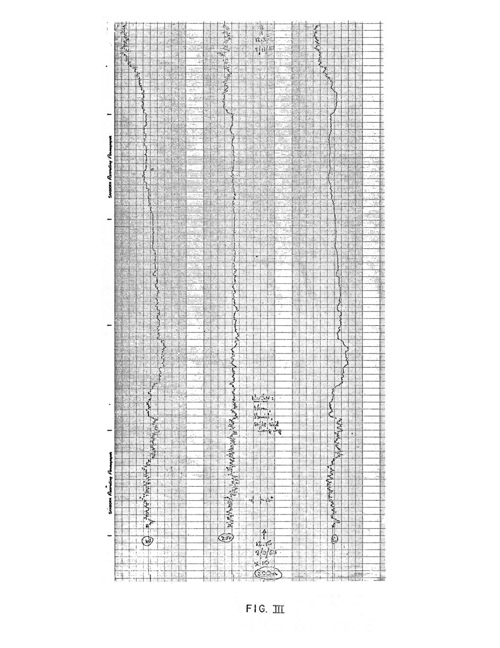
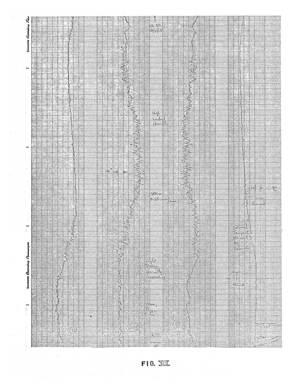
2 ATMOSPHERIC PATH FLUCTUATIONS IN THE ATMOSPHERE: A PRELIMINARY REPORT ON THE MEASUREMENT OF DIFFERENTIAL OVERGROUND PATH FLUCTUATIONS AT 5.6 KMc Nigel J. Keen. Abstract Two 10-foot dishes transmit CW signals horizontally in opposite directions from a central location. A plane reflector reflects each signal back to its respective dish, whereupon the phase of each returning signal is compared with the phase of the (common) outgoing signal. The phase fluctuations over each path are recorded digitally, while an analog record gives the single path fluctuations and the difference between these fluctuations. Typical records are shown in Figures I through VII. If the reflectors are each 300 meters from the dishes, rapid peak-to-peak differentia fluctuations (ev 1 minute) have magnitudes as great as 15 in warm, humid weather, and these fluctuations are uncorrelated: this is equivalent to a path fluctuation of 2.3 mm in 600 m. Slow differential fluctuations (>15 minute s) of twice this magnitude have been observed under similar atmospheric conditions, although really slow differential fluctuations (> 1 hour) appear to be absent in most cases. Single path fluctuations > 60 0 are observed with periods over several hours, suggesting that the large scale atmospheric fluctuations are usually well correlated. Rain appears to give short-term differential fluctuations larger than those without precipitation, even during the night (when path conditions are usually most stable). No attempt has been made at this stage statistically to analyze the digital data, nor have quantitative meteorological measurements been taken. However, we consider experimental results by other workers insofar as they are relevant to radio astronomical problems. II. Basic Considerations Microwave signals passing through the atmosphere suffer random variations of path-length, mainly due to the variation of water-vapor in the wave-path. * These * The variation of path length depends on the distribution of the precipitable water, as well as on the q uantit y, although we will not attempt to separate the causes here.
3 variations may affect radio astronomical interferometer observations in two ways. In the first place, source signals arriving at the two antennas of an interferometer may suffer uncorrelated delays prior to arrival at each dish. Also, local oscillator signals may experience random phase fluctuations if transmitted by a radio link. Both phenomena will produce a random movement of the interferometer fringes, and our experiment allows us to make some quantitative judgments about overground path fluctuations. Furthermore, Tatarski [I] has performed experiments on intensity (rather than phase) fluctuations of a beam of light transmitted overground, and has obtained the spectral distribution of these fluctuations. We will discuss these results briefly later in this report. The spectrum of phase fluctuations will be obtained at NRAO when sufficient data is available to p ermit a statistical analysis of the phase fluctuation spectrum. III. Theoretical and Ex erimental Considerations We wish to study the nature of the fluctuations in electrical path through the atmosphere. These fluctuations depend on the variations in temperature and absolute humidity of the atmosphere, although there are two mathematical processes occurring simultaneously to produce these fluctuations: (a) Turbulence which may be considered on a statistical model; and (b) Non-statistical (quasi-systematic) atmospheric processes, such as radiation losses and frontal movements. Tatarski has studied the path fluctuations in a turbulent medium and finds that the structure function -p D f (r i, r 2 ) = [f(r1) is given by where -+ r r 4. r 2 i ) r2/3 Hence the rms path fluctuations are given by R
4 This is in agreement with the experimental results of Gossard [2], where temperature, humidity and refractive index measurements were made from aircraft and balloons. The use of the structure function rather than the correlation function permits the idea of locally homogeneous and isotropic random fields, without regard to f(r). This concept is also employed by Booker [3] although that author uses a Gaussian model of turbulence (in the ionosphere). We have to consider the upper scale of turbulence where a gross, quasisystematic process causes turbulence to commence and the lower scale of turbulence where sufficient energy is lost to permit laminar flow to commence. Since the lower scale of turbulence does not exceed a few millimeters in the atmosphere [1, p. 210], we only concern ourselves with the upper scale, L. The variation of structure lune- tion with r is shown in Figure VIII and the rms variation of path difference is shown (on logarithmic scale) in Figure IX. The transition from turbulence to quasi-systematic flow is not sudden, but extends over a considerable range of r (shown by the full line). The system employed by the National Bureau of Standards, Boulder, Colorado [4] is shown in Figure X. Here the transition is even longer, and is qualitatively predicted by von Hoerner [5] as shown dotted in Figure IX. This appears to be in agreement with the experimental results of NBS [4, p. 69]. Considering the uncorrelated path fluctuations for a signal arriving at the two dishes of an interferometer, the rms apparent angular movement of a source is r 1/3-2/3 r adians, which means that larger angular position fluctuations (fur ) should occur at shorter spacings due to turbulence alone. Tatarski predicts [1, p. 227] that the "quivering" of optical source images decreases slowly as the (filled) aperture diameter is increased, although, as he points out, most of the experimental work has been performed on amplitude fluctuations of sources, rather than on phase (direction) fluctuations. An interesting aspect of Tatarski' s experimental intensity fluctuation s p ectra [1, pp ] is the considerabl y reduced amplitude of fluctuations < 20 cis in winter (compared with summer), suggesting less large scale turbulons. Unfortunately,
5 Tatarski did not observe below 2 c/s. Caution should be used in comparing optical and microwave results, however, since it is suggested [6] that optical fluctuations are primarily a high altitude temperature effect. Megaw [7] [1-1:] studied direction- and intensity-fluctuations at both radio and optical Wavelength. It is important to determine the upper scale of turbulence, L. Tatarsld and Gossard independently found L c o m [1, p. 2661*. In high resolution radio astronomy we are concerned with fluctuations in paths separated by distances > L. Hence we must now consider quasi-systematic atmospheric fluctuations, which means that path fluctuations to the two (or more) dishes of a high resolution instrument must be considered empirically. Site meteorological conditions (especially the total atmospheric water content) will tend to dictate an approximate resolution limit for a highresolution instrument. Furthermore, as with turbulence, we are especially interested in the lower layers of the atmosphere. Barton [8} has evaluated the NBS data, and computes atmospheric path fluctuations for a 2200-meter baseline (10 arc second fringes at X = 11 cm) which produce out-and-return rms position errors between 1. 5 and 4 arc seconds over 1000 seconds. This gives one-way fringe fluctuations < 2 arc seconds, and greater for shorter integration times. For a 1100-meter baseline the fluctuations are a little more (< 2.5 arc seconds) than for 2200-meters. This appears to indicate that random fringe fluctuations approach an asymptotic limit not much smaller than 2 arc seconds, and hence percentage fringe fluctuations will increase rapidly below 10 arc seconds. Drake [9] determined the positions of various radio sources using the NRAO 85-foot telescope at A = 3.75 cm. He claims an overall rms error of about 3 arc seconds, including a maximum position-reading accuracy of < 2 arc seconds. Results for Cygnus A are shown in Figure XI, and the resultant errors will certainly be < 5 arc seconds. Drake [10] states that the receiver accounts for at least 3 arc seconds of this error, so rms single-beam errors due to atmospheric fluctuation appear to be * According to Tatarski, we are unable to determine the "upper scale of turbulence". What we find is the order of the maximum correlation distance.
6 A, 1 arc second. However, there has been some difficulty in assessing the experimental errors of the system. IV. The Differer _ surin S stem The system is shown in the block schematic diagram (Figure XII). A klystron is monitored by a crystal oscillator at 5. 6 kmc, and transmits a signal from two 10- foot antennas facing in opposite directions. The signals are reflected back to the antennas by two plane reflectors, 8-foot square. The arrangement is shown in Figure XCII, together with possible reflector locations. Three out-and-return path distances are available: 200 m, 600 m, and 1000 m. The geographical situation is shown in Figure XIV. A 1000 cis sawtooth waveform is generated (in a special oscillator developed at NRAO) and applied to the helix of a traveling wave tube amplifier. Since a TWT is phase modulated by varying the helix voltage, correct choice of sawtooth amplitude permits 360 of phase change for each sawtooth cycle. If the sawtooth fly-back time is very short, the microwave signal experiences a uniform frequency change equal to the sawtooth frequency. Part of the oscillator signal is passed through the sawtooth-modulated TWT and the output of the TWT is mixed with the returned microwave signal from each path. The output from each mixer is passed through a 1000 cis filter so that the filter outputs are 1000 cis sine waves containing the information on the phase fluctuations. Since the sawtooth waveform is the 1000 cis reference, it is filtered until only a 1000 c/s sine wave remains. The sine wave from each path is then compared with the reference (filtered sa.wtooth). The returned signal is isolated from the outgoing signal by a 50 db isolator, specially selected for the purpose. In the original apparatus, designed by M. Vinokur for determining phase fluctuations along a single path, the comparison of the phases of received and transmitted signals was obtained in an Ad-Yu meter. The output of this meter was a voltage proportional to phase difference. In the two path equipment described here, the sine waves are converted to square waves in "zero-crossover" detectors built at NRAO. The
7 leading edges of these square waves are coincident with the zero crossover of the sine waves to within 0.3 for sine wave amplitudes between 2 volts and 15 volts. The leading edge of the reference is used to open a gate, and allows a train of 1 Mc pulses to pass to a counter until the leading edge of one of the returned-signal square waves (we call them "East" and "West") closes the gate. Hence direct counting of the pulses would give one thousand pulses for a phase difference. Trains of East and West pulses are summed alternately in the counter g re l irh ul al i ayi eg. second or eight seconds, may be pre-selected. Phase shifters permit convenient phase reference levels to be selected. In order to simplify digital logic the output of the counter is divided down so that 1000 pulses represent of phase change. Hence only three decimal digits are required for each observation of phase Since East and West phases are recorded alternately, a digital marker is generated for each reading, which indicates whether the path being considered is East or West. Hence, together with the end-of-line marker, five characters are punched out every half second or every 8 seconds. This is well within the capability of the NRAO scanner and the Friden. punch. One further feature of the system is the analog record. The output of the counter is alternately passed to the "East buffer" and the 'West buffer' where digital-to-analog converters turn the pulses into a DC voltage proportional to the count stored in either buffer. The voltage from each d-to-a unit is recorded on a Sanborn 4-channel recorder, together with the difference between the voltages. Hence we have a digital record of East and West phases, relative to some arbitrary reference phase, and an analog record of East, West and Difference phases. Typical analog records are shown in Figures I through VII. Interesting aspects of the equipment described are: (1) The reliability of the Computer Control Company logic cards, used for all digital circuits; (2) The use of the phase modulated TWT, and its considerable temperature dependence; (3) The necessity for consthnt VSIATR checks and a very stable oscillator frequency; and
8 (4) The extreme care required in aligning antennas and V. Exjrimentai Res-alts Results to date have been for path distances of 600 meters, although 200 meters were initially used to calibrate the equipment. Digital records have been obtained, although sufficient data is not yet available to make a spectral analysis of phase fluctuations. For the time being we can only make quantitative judgments from the analog records (Figures From these records we see: (1) Since difference fluctuations will give the uncorrelated fluctuations in each path, short-term (turbulent) fluctuations are the main feature of the difference record; longterm (quasi-systematic) fluctuations appear fairly well correlated. (2) Short-term I minute) peak-to-peak fluctuations as great as 15 are observed in warm, humid weather. This is equivalent to a maximum path fluctuation of 2.3 mm in 600 m. (3) Short-term fluctuations appeal to be uncorrelated, although fluctuations > 15 minutes are sometimes uncorrelated also. (4) The only large slow fluctuation of the difference record ( ",several hours) occured at the end of a spell of low humidity weather (Figure VI). This does not appear to be an instrumental effect. There was little or no wind during the night, although the West side is more protected than the East side. The large rapid East fluctuations during the night are also extraordinary.
9 (5) Extremely large correlated and uncorrelated phase fluctuations (-v40 ) occur with the advent of rain. (6) Long- and short-term phase fluctuations are very much smaller during the night than during the day (with the exception of the East record on Figure VI). VI. Conclusions Since insufficient information is available at the moment a detailed spectral analysis is not yet possible. However, indicative results may contribute something to an understanding of atmospheric behavior at microwave frequencies. References [1] 'Wave Propagation in a Turbulent Medium", Tatraski. McGraw-Hill (1961). [2] "Power Spectra of Temperature, Humidity and Refractive Index from Aircraft and Tethered Balloon Measurements". E. E. Gossard. Trans. IRE, Ap. 8 (1960), 186. [3] "The Use of Radio Stars to Study Irregular Refraction of Radio Waves in the Ionosphere", H. G. Booker. Proc.. IRE 46 (1958) [4] "An Experimental Study of Phase Variations in Line-of-Sight Microwave Transmissions!!, K. A. Norton, et al.,nbs Monograph 33 (19461). [5] S. von Hoerner, private communication. [6] "Die Szintillation der Sterne", H. Eisasser. Die Naturwissenschaften, 47 (1960), 6. [7] "Scattering of Electromagnetic Waves by Atmospheric `rurouience", Mega,w. Nature, 166 (1950), [8] "Reasons for the Failture of Radio Interferometers to Achieve Their Expected Accuracy", D. K. Barton. Proc., IEEE, 51 (1963), 626. [9] "The Position-Determination Program of the NRAO", F. D. Drake. P. A. S. Pacific, 72 (1960), 494. [10] F. D. Drake, private communication. [11] "Fundamental Radio Scatter Propagation Theory", Megaw. P. I. E. E. (Brit.), 104C (1957), 441.
10
11
12

13
14

15
16
17
18
19

20
21
22

23
DECEMBER 1964 NUMBER OF COPIES: 75
 NATIONAL RADIO ASTRONOMY OBSERVATORY Green Bank, West Virginia E ectronics Division Internal Report No. 42 A DIGITAL CROSS-CORRELATION INTERFEROMETER Nigel J. Keen DECEMBER 964 NUMBER OF COPIES: 75 A DIGITAL
SEPTEMBER 1963 NUMBER OF COPIES: 100
 NATIONAL RADIO ASTRONOMY OBSERVATORY Green Bank, West Virginip, Electronics Division Internal Report Nos 19 A PROTOTYPE DIGITAL CROSS-CORRELATOR FOR THE NRAO INTERFEROMETER Nigel J. Keen SEPTEMBER 1963
SEPTE1VIBER 1963 NUMBER OF COPIES: 100
 NATIONAL RADIO ASTRONOMY OBSERVATORY Green Bank, West Virginia Electronics Division Internal Report No. 18 POSSIBLE DESIGNS FOR A VERY LARGE ARRAY OF ANTENNAS Nigel J. Keen SEPTE1VIBER 1963 NUMBER OF COPIES:
Fundamentals of Radio Interferometry
 Fundamentals of Radio Interferometry Rick Perley, NRAO/Socorro Fourteenth NRAO Synthesis Imaging Summer School Socorro, NM Topics Why Interferometry? The Single Dish as an interferometer The Basic Interferometer
NATIONAL RADIO ASTRONOMY OBSERVATORY Green Bank, West Virginia Electronics Division Internal Report No 76
 NATIONAL RADIO ASTRONOMY OBSERVATORY Green Bank, West Virginia Electronics Division Internal Report No 76 A NOVEL WAY OF BEAM-SWITCHING, PARTICULARLY SUITABLE AT MM WAVELENGTHS N. Albaugh and K. H. Wesseling
Why Single Dish? Darrel Emerson NRAO Tucson. NAIC-NRAO School on Single-Dish Radio Astronomy. Green Bank, August 2003.
 Why Single Dish? Darrel Emerson NRAO Tucson NAIC-NRAO School on Single-Dish Radio Astronomy. Green Bank, August 2003. Why Single Dish? What's the Alternative? Comparisons between Single-Dish, Phased Array
NTT DOCOMO Technical Journal. Method for Measuring Base Station Antenna Radiation Characteristics in Anechoic Chamber. 1.
 Base Station Antenna Directivity Gain Method for Measuring Base Station Antenna Radiation Characteristics in Anechoic Chamber Base station antennas tend to be long compared to the wavelengths at which
EC ANTENNA AND WAVE PROPAGATION
 EC6602 - ANTENNA AND WAVE PROPAGATION FUNDAMENTALS PART-B QUESTION BANK UNIT 1 1. Define the following parameters w.r.t antenna: i. Radiation resistance. ii. Beam area. iii. Radiation intensity. iv. Directivity.
AMPLITUDE MODULATION
 AMPLITUDE MODULATION PREPARATION...2 theory...3 depth of modulation...4 measurement of m... 5 spectrum... 5 other message shapes.... 5 other generation methods...6 EXPERIMENT...7 aligning the model...7
THE NATURE OF GROUND CLUTTER AFFECTING RADAR PERFORMANCE MOHAMMED J. AL SUMIADAEE
 International Journal of Electronics, Communication & Instrumentation Engineering Research and Development (IJECIERD) ISSN(P): 2249-684X; ISSN(E): 2249-7951 Vol. 6, Issue 2, Apr 2016, 7-14 TJPRC Pvt. Ltd.
Sideband Smear: Sideband Separation with the ALMA 2SB and DSB Total Power Receivers
 and DSB Total Power Receivers SCI-00.00.00.00-001-A-PLA Version: A 2007-06-11 Prepared By: Organization Date Anthony J. Remijan NRAO A. Wootten T. Hunter J.M. Payne D.T. Emerson P.R. Jewell R.N. Martin
Fundamentals of Radio Interferometry
 Fundamentals of Radio Interferometry Rick Perley, NRAO/Socorro ATNF Radio Astronomy School Narrabri, NSW 29 Sept. 03 Oct. 2014 Topics Introduction: Sensors, Antennas, Brightness, Power Quasi-Monochromatic
1. Explain how Doppler direction is identified with FMCW radar. Fig Block diagram of FM-CW radar. f b (up) = f r - f d. f b (down) = f r + f d
 = f r - f d. f b (down) = f r + f d") 1. Explain how Doppler direction is identified with FMCW radar. A block diagram illustrating the principle of the FM-CW radar is shown in Fig. 4.1.1 A portion of the transmitter signal acts as the reference
1. Explain how Doppler direction is identified with FMCW radar. A block diagram illustrating the principle of the FM-CW radar is shown in Fig. 4.1.1 A portion of the transmitter signal acts as the reference
Theoretical Aircraft Overflight Sound Peak Shape
 Theoretical Aircraft Overflight Sound Peak Shape Introduction and Overview This report summarizes work to characterize an analytical model of aircraft overflight noise peak shapes which matches well with
6 Experiment II: Law of Reflection
 Lab 6: Microwaves 3 Suggested Reading Refer to the relevant chapters, 1 Introduction Refer to Appendix D for photos of the apparatus This lab allows you to test the laws of reflection, refraction and diffraction
DRAFT. Enhanced Image Rejection in Receivers with Sideband-Separating Mixers. A. R. Kerr 21 December 2006
 EnhancedImageRejection03.wpd DRAFT Enhanced Image Rejection in Receivers with Sideband-Separating ixers A. R. Kerr 2 December 2006 ABSTRACT: The finite image rejection of a spectrometer using a sideband-separating
Module 1: Introduction to Experimental Techniques Lecture 2: Sources of error. The Lecture Contains: Sources of Error in Measurement
 The Lecture Contains: Sources of Error in Measurement Signal-To-Noise Ratio Analog-to-Digital Conversion of Measurement Data A/D Conversion Digitalization Errors due to A/D Conversion file:///g /optical_measurement/lecture2/2_1.htm[5/7/2012
MIL-STD-202G METHOD 308 CURRENT-NOISE TEST FOR FIXED RESISTORS
 CURRENT-NOISE TEST FOR FIXED RESISTORS 1. PURPOSE. This resistor noise test method is performed for the purpose of establishing the "noisiness" or "noise quality" of a resistor in order to determine its
KULLIYYAH OF ENGINEERING
 KULLIYYAH OF ENGINEERING DEPARTMENT OF ELECTRICAL & COMPUTER ENGINEERING ANTENNA AND WAVE PROPAGATION LABORATORY (ECE 4103) EXPERIMENT NO 3 RADIATION PATTERN AND GAIN CHARACTERISTICS OF THE DISH (PARABOLIC)
VLA CONFIGURATION STUDY - STATUS REPORT. February 27, 1968
 VLA CONFIGURATION STUDY - STATUS REPORT February 27, 1968 Summary of Work for the Period January 1967 - February 1968 The work done during the period under review can be divided into four categories: (i)
To print higher-resolution math symbols, click the Hi-Res Fonts for Printing button on the jsmath control panel.
 To print higher-resolution math symbols, click the Hi-Res Fonts for Printing button on the jsmath control panel. Radiometers Natural radio emission from the cosmic microwave background, discrete astronomical
Why Single Dish? Darrel Emerson NRAO Tucson. NAIC-NRAO School on Single-Dish Radio Astronomy. Green Bank, August 2003.
 Why Single Dish? Darrel Emerson NRAO Tucson NAIC-NRAO School on Single-Dish Radio Astronomy. Green Bank, August 2003. Why Single Dish? What's the Alternative? Comparisons between Single-Dish, Phased Array
Antennas & Propagation. CSG 250 Fall 2007 Rajmohan Rajaraman
 Antennas & Propagation CSG 250 Fall 2007 Rajmohan Rajaraman Introduction An antenna is an electrical conductor or system of conductors o Transmission - radiates electromagnetic energy into space o Reception
SCATTERING POLARIMETRY PART 1. Dr. A. Bhattacharya (Slide courtesy Prof. E. Pottier and Prof. L. Ferro-Famil)
") SCATTERING POLARIMETRY PART 1 Dr. A. Bhattacharya (Slide courtesy Prof. E. Pottier and Prof. L. Ferro-Famil) 2 That s how it looks! Wave Polarisation An electromagnetic (EM) plane wave has time-varying
SCATTERING POLARIMETRY PART 1 Dr. A. Bhattacharya (Slide courtesy Prof. E. Pottier and Prof. L. Ferro-Famil) 2 That s how it looks! Wave Polarisation An electromagnetic (EM) plane wave has time-varying
Reading 28 PROPAGATION THE IONOSPHERE
 Reading 28 Ron Bertrand VK2DQ http://www.radioelectronicschool.com PROPAGATION THE IONOSPHERE The ionosphere is a region of the upper atmosphere extending from a height of about 60 km to greater than 500
Spectral Analysis of the LUND/DMI Earthshine Telescope and Filters
 Spectral Analysis of the LUND/DMI Earthshine Telescope and Filters 12 August 2011-08-12 Ahmad Darudi & Rodrigo Badínez A1 1. Spectral Analysis of the telescope and Filters This section reports the characterization
Magnetic Tape Recorder Spectral Purity
 Magnetic Tape Recorder Spectral Purity Item Type text; Proceedings Authors Bradford, R. S. Publisher International Foundation for Telemetering Journal International Telemetering Conference Proceedings
Know how Pulsed Doppler radar works and how it s able to determine target velocity. Know how the Moving Target Indicator (MTI) determines target
 determines target") Moving Target Indicator 1 Objectives Know how Pulsed Doppler radar works and how it s able to determine target velocity. Know how the Moving Target Indicator (MTI) determines target velocity. Be able to
Moving Target Indicator 1 Objectives Know how Pulsed Doppler radar works and how it s able to determine target velocity. Know how the Moving Target Indicator (MTI) determines target velocity. Be able to
Exercise 1-4. The Radar Equation EXERCISE OBJECTIVE DISCUSSION OUTLINE DISCUSSION OF FUNDAMENTALS
 Exercise 1-4 The Radar Equation EXERCISE OBJECTIVE When you have completed this exercise, you will be familiar with the different parameters in the radar equation, and with the interaction between these
Estimation of speed, average received power and received signal in wireless systems using wavelets
 Estimation of speed, average received power and received signal in wireless systems using wavelets Rajat Bansal Sumit Laad Group Members rajat@ee.iitb.ac.in laad@ee.iitb.ac.in 01D07010 01D07011 Abstract
NATIONAL RADIO ASTRONOMY OBSERVATORY Green Bank, West Virginia Electronics Division Internal Report No. 136
 NATIONAL RADIO ASTRONOMY OBSERVATORY Green Bank, West Virginia Electronics Division Internal Report No. 136 AN ANTENNA MEASURING INSTRUMENT AND ITS USE ON THE 140-FOOT TELESCOPE J. 'W. Findlay and John
Why Single Dish? Why Single Dish? Darrel Emerson NRAO Tucson
 Why Single Dish? Darrel Emerson NRAO Tucson Why Single Dish? What's the Alternative? Comparisons between Single-Dish, Phased Array & Interferometers Advantages and Disadvantages of Correlation Interferometer
L- and S-Band Antenna Calibration Using Cass. A or Cyg. A
 L- and S-Band Antenna Calibration Using Cass. A or Cyg. A Item Type text; Proceedings Authors Taylor, Ralph E. Publisher International Foundation for Telemetering Journal International Telemetering Conference
SPATIAL DIVERSITY TECHNIQUES IN MIMO WITH FREE SPACE OPTICAL COMMUNICATION
 SPATIAL DIVERSITY TECHNIQUES IN MIMO WITH FREE SPACE OPTICAL COMMUNICATION Ruchi Modi 1, Vineeta Dubey 2, Deepak Garg 3 ABESEC Ghaziabad India, IPEC Ghaziabad India, ABESEC,Gahziabad (India) ABSTRACT In
Chapter-15. Communication systems -1 mark Questions
 Chapter-15 Communication systems -1 mark Questions 1) What are the three main units of a Communication System? 2) What is meant by Bandwidth of transmission? 3) What is a transducer? Give an example. 4)
PRINCIPLES OF RADAR. By Members of the Staff of the Radar School Massachusetts Institute of Technology. Third Edition by J.
 PRINCIPLES OF RADAR By Members of the Staff of the Radar School Massachusetts Institute of Technology Third Edition by J. Francis Reintjes ASSISTANT PBOFESSOR OF COMMUNICATIONS MASSACHUSETTS INSTITUTE
Radar Equations. for Modern Radar. David K. Barton ARTECH HOUSE BOSTON LONDON. artechhouse.com
 Radar Equations for Modern Radar David K Barton ARTECH HOUSE BOSTON LONDON artechhousecom Contents Preface xv Chapter 1 Development of the Radar Equation 1 11 Radar Equation Fundamentals 1 111 Maximum
UNIT Derive the fundamental equation for free space propagation?
 UNIT 8 1. Derive the fundamental equation for free space propagation? Fundamental Equation for Free Space Propagation Consider the transmitter power (P t ) radiated uniformly in all the directions (isotropic),
Antennas and Propagation
 Antennas and Propagation Chapter 5 Introduction An antenna is an electrical conductor or system of conductors Transmission - radiates electromagnetic energy into space Reception - collects electromagnetic
The Discussion of this exercise covers the following points:
 Exercise 3-2 Frequency-Modulated CW Radar EXERCISE OBJECTIVE When you have completed this exercise, you will be familiar with FM ranging using frequency-modulated continuous-wave (FM-CW) radar. DISCUSSION
Narrow- and wideband channels
 RADIO SYSTEMS ETIN15 Lecture no: 3 Narrow- and wideband channels Ove Edfors, Department of Electrical and Information technology Ove.Edfors@eit.lth.se 27 March 2017 1 Contents Short review NARROW-BAND
First and second order systems. Part 1: First order systems: RC low pass filter and Thermopile. Goals: Department of Physics
 slide 1 Part 1: First order systems: RC low pass filter and Thermopile Goals: Understand the behavior and how to characterize first order measurement systems Learn how to operate: function generator, oscilloscope,
Development of Control Algorithm for Ring Laser Gyroscope
 International Journal of Scientific and Research Publications, Volume 2, Issue 10, October 2012 1 Development of Control Algorithm for Ring Laser Gyroscope P. Shakira Begum, N. Neelima Department of Electronics
RECOMMENDATION ITU-R S.733-1* (Question ITU-R 42/4 (1990))**
)**") Rec. ITU-R S.733-1 1 RECOMMENDATION ITU-R S.733-1* DETERMINATION OF THE G/T RATIO FOR EARTH STATIONS OPERATING IN THE FIXED-SATELLITE SERVICE (Question ITU-R 42/4 (1990))** Rec. ITU-R S.733-1 (1992-1993)
Rec. ITU-R S.733-1 1 RECOMMENDATION ITU-R S.733-1* DETERMINATION OF THE G/T RATIO FOR EARTH STATIONS OPERATING IN THE FIXED-SATELLITE SERVICE (Question ITU-R 42/4 (1990))** Rec. ITU-R S.733-1 (1992-1993)
Introduction to Radio Astronomy
 Introduction to Radio Astronomy The Visible Sky, Sagittarius Region 2 The Radio Sky 3 4 Optical and Radio can be done from the ground! 5 Outline The Discovery of Radio Waves Maxwell, Hertz and Marconi
ALMA Memo #289 Atmospheric Noise in Single Dish Observations Melvyn Wright Radio Astronomy Laboratory, University of California, Berkeley 29 February
 ALMA Memo #289 Atmospheric Noise in Single Dish Observations Melvyn Wright Radio Astronomy Laboratory, University of California, Berkeley 29 February 2000 Abstract Atmospheric noise and pointing fluctuations
9. Microwaves. 9.1 Introduction. Safety consideration
 MW 9. Microwaves 9.1 Introduction Electromagnetic waves with wavelengths of the order of 1 mm to 1 m, or equivalently, with frequencies from 0.3 GHz to 0.3 THz, are commonly known as microwaves, sometimes
EVLA System Commissioning Results
 EVLA System Commissioning Results EVLA Advisory Committee Meeting, March 19-20, 2009 Rick Perley EVLA Project Scientist t 1 Project Requirements EVLA Project Book, Chapter 2, contains the EVLA Project
A NOVEL DIGITAL BEAMFORMER WITH LOW ANGLE RESOLUTION FOR VEHICLE TRACKING RADAR
 Progress In Electromagnetics Research, PIER 66, 229 237, 2006 A NOVEL DIGITAL BEAMFORMER WITH LOW ANGLE RESOLUTION FOR VEHICLE TRACKING RADAR A. Kr. Singh, P. Kumar, T. Chakravarty, G. Singh and S. Bhooshan
ERRATUM: In accordance with the standardized nomenciaure adopted at NRAO, the term "instrumental. meridian" should now be "instrumental equator".
 ERRATUM: In accordance with the standardized nomenciaure adopted at NRAO, the term "instrumental. meridian" should now be "instrumental equator". NATIONAL RADIO ASTRONOMY OBSERVATORY Green Bank, West Virginia
Satellite Signals and Communications Principles. Dr. Ugur GUVEN Aerospace Engineer (P.hD)
") Satellite Signals and Communications Principles Dr. Ugur GUVEN Aerospace Engineer (P.hD) Principle of Satellite Signals In essence, satellite signals are electromagnetic waves that travel from the satellite
Satellite Signals and Communications Principles Dr. Ugur GUVEN Aerospace Engineer (P.hD) Principle of Satellite Signals In essence, satellite signals are electromagnetic waves that travel from the satellite
The 34th International Physics Olympiad
 The 34th International Physics Olympiad Taipei, Taiwan Experimental Competition Wednesday, August 6, 2003 Time Available : 5 hours Please Read This First: 1. Use only the pen provided. 2. Use only the
Symmetry in the Ka-band Correlation Receiver s Input Circuit and Spectral Baseline Structure NRAO GBT Memo 248 June 7, 2007
 Symmetry in the Ka-band Correlation Receiver s Input Circuit and Spectral Baseline Structure NRAO GBT Memo 248 June 7, 2007 A. Harris a,b, S. Zonak a, G. Watts c a University of Maryland; b Visiting Scientist,
AN ADAPTIVE MOBILE ANTENNA SYSTEM FOR WIRELESS APPLICATIONS
 AN ADAPTIVE MOBILE ANTENNA SYSTEM FOR WIRELESS APPLICATIONS G. DOLMANS Philips Research Laboratories Prof. Holstlaan 4 (WAY51) 5656 AA Eindhoven The Netherlands E-mail: dolmans@natlab.research.philips.com
First Observation of Stimulated Coherent Transition Radiation
 SLAC 95 6913 June 1995 First Observation of Stimulated Coherent Transition Radiation Hung-chi Lihn, Pamela Kung, Chitrlada Settakorn, and Helmut Wiedemann Applied Physics Department and Stanford Linear
Microwave Optics. Department of Physics & Astronomy Texas Christian University, Fort Worth, TX. January 16, 2014
 Microwave Optics Department of Physics & Astronomy Texas Christian University, Fort Worth, TX January 16, 2014 1 Introduction Optical phenomena may be studied at microwave frequencies. Visible light has
MMA RECEIVERS: HFET AMPLIFIERS
 MMA Project Book, Chapter 5 Section 4 MMA RECEIVERS: HFET AMPLIFIERS Marian Pospieszalski Ed Wollack John Webber Last revised 1999-04-09 Revision History: 1998-09-28: Added chapter number to section numbers.
Narrow- and wideband channels
 RADIO SYSTEMS ETIN15 Lecture no: 3 Narrow- and wideband channels Ove Edfors, Department of Electrical and Information technology Ove.Edfors@eit.lth.se 2012-03-19 Ove Edfors - ETIN15 1 Contents Short review
Project = An Adventure : Wireless Networks. Lecture 4: More Physical Layer. What is an Antenna? Outline. Page 1
 Project = An Adventure 18-759: Wireless Networks Checkpoint 2 Checkpoint 1 Lecture 4: More Physical Layer You are here Done! Peter Steenkiste Departments of Computer Science and Electrical and Computer
ELEC4604. RF Electronics. Experiment 1
 ELEC464 RF Electronics Experiment ANTENNA RADATO N PATTERNS. ntroduction The performance of RF communication systems depend critically on the radiation characteristics of the antennae it employs. These
J/K). Nikolova
. Nikolova") Lecture 7: ntenna Noise Temperature and System Signal-to-Noise Ratio (Noise temperature. ntenna noise temperature. System noise temperature. Minimum detectable temperature. System signal-to-noise ratio.)
Lecture 7: ntenna Noise Temperature and System Signal-to-Noise Ratio (Noise temperature. ntenna noise temperature. System noise temperature. Minimum detectable temperature. System signal-to-noise ratio.)
Subsystems of Radar and Signal Processing and ST Radar
 Advance in Electronic and Electric Engineering. ISSN 2231-1297, Volume 3, Number 5 (2013), pp. 531-538 Research India Publications http://www.ripublication.com/aeee.htm Subsystems of Radar and Signal Processing
Federal Communications Commission Office of Engineering and Technology Laboratory Division
 Federal Communications Commission Office of Engineering and Technology Laboratory Division May 2, 2017 GUIDELINES FOR COMPLIANCE TESTING OF UNLICENSED NATIONAL INFORMATION INFRASTRUCTURE (U-NII) DEVICES
Fundamentals of Radio Interferometry
 Fundamentals of Radio Interferometry Rick Perley, NRAO/Socorro 15 th Synthesis Imaging School Socorro, NM 01 09 June, 2016 Topics The Need for Interferometry Some Basics: Antennas as E-field Converters
CHAPTER 5 FINE-TUNING OF AN ECDL WITH AN INTRACAVITY LIQUID CRYSTAL ELEMENT
 CHAPTER 5 FINE-TUNING OF AN ECDL WITH AN INTRACAVITY LIQUID CRYSTAL ELEMENT In this chapter, the experimental results for fine-tuning of the laser wavelength with an intracavity liquid crystal element
Antennas and Propagation
 CMPE 477 Wireless and Mobile Networks Lecture 3: Antennas and Propagation Antennas Propagation Modes Line of Sight Transmission Fading in the Mobile Environment Introduction An antenna is an electrical
ARTICLE 22. Space services 1
 CHAPTER VI Provisions for services and stations RR22-1 ARTICLE 22 Space services 1 Section I Cessation of emissions 22.1 1 Space stations shall be fitted with devices to ensure immediate cessation of their
THE PROPAGATION OF PARTIAL DISCHARGE PULSES IN A HIGH VOLTAGE CABLE
 THE PROPAGATION OF PARTIAL DISCHARGE PULSES IN A HIGH VOLTAGE CABLE Z.Liu, B.T.Phung, T.R.Blackburn and R.E.James School of Electrical Engineering and Telecommuniications University of New South Wales
Rec. ITU-R F RECOMMENDATION ITU-R F *
 Rec. ITU-R F.162-3 1 RECOMMENDATION ITU-R F.162-3 * Rec. ITU-R F.162-3 USE OF DIRECTIONAL TRANSMITTING ANTENNAS IN THE FIXED SERVICE OPERATING IN BANDS BELOW ABOUT 30 MHz (Question 150/9) (1953-1956-1966-1970-1992)
Dr. Martina B. Arndt Physics Department Bridgewater State College (MA) Based on work by Dr. Alan E.E. Rogers MIT s Haystack Observatory (MA)
 Based on work by Dr. Alan E.E. Rogers MIT s Haystack Observatory (MA)") VSRT INTRODUCTION Dr Martina B Arndt Physics Department Bridgewater State College (MA) Based on work by Dr Alan EE Rogers MIT s Haystack Observatory (MA) August, 2009 1 PREFACE The Very Small Radio Telescope
VSRT INTRODUCTION Dr Martina B Arndt Physics Department Bridgewater State College (MA) Based on work by Dr Alan EE Rogers MIT s Haystack Observatory (MA) August, 2009 1 PREFACE The Very Small Radio Telescope
Experiment 12: Microwaves
 MASSACHUSETTS INSTITUTE OF TECHNOLOGY Department of Physics 8.02 Spring 2005 OBJECTIVES Experiment 12: Microwaves To observe the polarization and angular dependence of radiation from a microwave generator
Rec. ITU-R P RECOMMENDATION ITU-R P PROPAGATION BY DIFFRACTION. (Question ITU-R 202/3)
") Rec. ITU-R P.- 1 RECOMMENDATION ITU-R P.- PROPAGATION BY DIFFRACTION (Question ITU-R 0/) Rec. ITU-R P.- (1-1-1-1-1-1-1) The ITU Radiocommunication Assembly, considering a) that there is a need to provide
Rec. ITU-R P.- 1 RECOMMENDATION ITU-R P.- PROPAGATION BY DIFFRACTION (Question ITU-R 0/) Rec. ITU-R P.- (1-1-1-1-1-1-1) The ITU Radiocommunication Assembly, considering a) that there is a need to provide
λ iso d 4 π watt (1) + L db (2)
 + L db (2)") 1 Path-loss Model for Broadcasting Applications and Outdoor Communication Systems in the VHF and UHF Bands Constantino Pérez-Vega, Member IEEE, and José M. Zamanillo Communications Engineering Department
1 Path-loss Model for Broadcasting Applications and Outdoor Communication Systems in the VHF and UHF Bands Constantino Pérez-Vega, Member IEEE, and José M. Zamanillo Communications Engineering Department
Understanding the performance of atmospheric free-space laser communications systems using coherent detection
 !"#$%&'()*+&, Understanding the performance of atmospheric free-space laser communications systems using coherent detection Aniceto Belmonte Technical University of Catalonia, Department of Signal Theory
ABSTRACT. Introduction
 THE LOW COST MICROWAVE RAIN SENSOR: STATE CERTIFICATION AND IMPLEMENTATION ON THE OBSERVATIONAL NET. A.V.Koldaev, A.I.Gusev, D.A.Konovalov. Central Aerological Observatory, Federal Service of Russia for
More Radio Astronomy
 More Radio Astronomy Radio Telescopes - Basic Design A radio telescope is composed of: - a radio reflector (the dish) - an antenna referred to as the feed on to which the radiation is focused - a radio
1 SINGLE TGT TRACKER (STT) TRACKS A SINGLE TGT AT FAST DATA RATE. DATA RATE 10 OBS/SEC. EMPLOYS A CLOSED LOOP SERVO SYSTEM TO KEEP THE ERROR SIGNAL
 TRACKS A SINGLE TGT AT FAST DATA RATE. DATA RATE 10 OBS/SEC. EMPLOYS A CLOSED LOOP SERVO SYSTEM TO KEEP THE ERROR SIGNAL") TRACKING RADARS 1 SINGLE TGT TRACKER (STT) TRACKS A SINGLE TGT AT FAST DATA RATE. DATA RATE 10 OBS/SEC. EMPLOYS A CLOSED LOOP SERVO SYSTEM TO KEEP THE ERROR SIGNAL SMALL. APPLICATION TRACKING OF AIRCRAFT/
TRACKING RADARS 1 SINGLE TGT TRACKER (STT) TRACKS A SINGLE TGT AT FAST DATA RATE. DATA RATE 10 OBS/SEC. EMPLOYS A CLOSED LOOP SERVO SYSTEM TO KEEP THE ERROR SIGNAL SMALL. APPLICATION TRACKING OF AIRCRAFT/
Modification of Earth-Space Rain Attenuation Model for Earth- Space Link
 IOSR Journal of Electronics and Communication Engineering (IOSR-JECE) e-issn: 2278-2834,p- ISSN: 2278-8735.Volume 9, Issue 2, Ver. VI (Mar - Apr. 2014), PP 63-67 Modification of Earth-Space Rain Attenuation
RADIO WAVE PROPAGATION
 CHAPTER 2 RADIO WAVE PROPAGATION Radio direction finding (RDF) deals with the direction of arrival of radio waves. Therefore, it is necessary to understand the basic principles involved in the propagation
PRELIMINARY STUDIES INTO THE REDUCTION OF DOME SEEING USING AIR CURTAINS
 Florence, Italy. May 2013 ISBN: 978-88-908876-0-4 DOI: 10.12839/AO4ELT3.13227 PRELIMINARY STUDIES INTO THE REDUCTION OF DOME SEEING USING AIR CURTAINS Scott Wells 1, Alastair Basden 1a, and Richard Myers
Radar level measurement - The users guide
 Radar level measurement The user's guide Radar level measurement - The users guide Peter Devine written by Peter Devine additional information Karl Grießbaum type setting and layout Liz Moakes final drawings
Receiver Performance and Comparison of Incoherent (bolometer) and Coherent (receiver) detection
 and Coherent (receiver) detection") At ev gap /h the photons have sufficient energy to break the Cooper pairs and the SIS performance degrades. Receiver Performance and Comparison of Incoherent (bolometer) and Coherent (receiver) detection
At ev gap /h the photons have sufficient energy to break the Cooper pairs and the SIS performance degrades. Receiver Performance and Comparison of Incoherent (bolometer) and Coherent (receiver) detection
Exercise 1-3. Radar Antennas EXERCISE OBJECTIVE DISCUSSION OUTLINE DISCUSSION OF FUNDAMENTALS. Antenna types
 Exercise 1-3 Radar Antennas EXERCISE OBJECTIVE When you have completed this exercise, you will be familiar with the role of the antenna in a radar system. You will also be familiar with the intrinsic characteristics
Section 1 Wireless Transmission
 Part : Wireless Communication! section : Wireless Transmission! Section : Digital modulation! Section : Multiplexing/Medium Access Control (MAC) Section Wireless Transmission Intro. to Wireless Transmission
Lecture Topics. Doppler CW Radar System, FM-CW Radar System, Moving Target Indication Radar System, and Pulsed Doppler Radar System
 Lecture Topics Doppler CW Radar System, FM-CW Radar System, Moving Target Indication Radar System, and Pulsed Doppler Radar System 1 Remember that: An EM wave is a function of both space and time e.g.
Antennas and Propagation. Chapter 5
 Antennas and Propagation Chapter 5 Introduction An antenna is an electrical conductor or system of conductors Transmission - radiates electromagnetic energy into space Reception - collects electromagnetic
Technical Considerations: Nuts and Bolts Project Planning and Technical Justification
 Technical Considerations: Nuts and Bolts Project Planning and Technical Justification Atacama Large Millimeter/submillimeter Array Expanded Very Large Array Robert C. Byrd Green Bank Telescope Very Long
Calculation and Comparison of Turbulence Attenuation by Different Methods
 16 L. DORDOVÁ, O. WILFERT, CALCULATION AND COMPARISON OF TURBULENCE ATTENUATION BY DIFFERENT METHODS Calculation and Comparison of Turbulence Attenuation by Different Methods Lucie DORDOVÁ 1, Otakar WILFERT
Introduction to Radio Interferometry Anand Crossley Alison Peck, Jim Braatz, Ashley Bemis (NRAO)
") Introduction to Radio Interferometry Anand Crossley Alison Peck, Jim Braatz, Ashley Bemis (NRAO) Atacama Large Millimeter/submillimeter Array Expanded Very Large Array Robert C. Byrd Green Bank Telescope
Introduction to Radio Interferometry Anand Crossley Alison Peck, Jim Braatz, Ashley Bemis (NRAO) Atacama Large Millimeter/submillimeter Array Expanded Very Large Array Robert C. Byrd Green Bank Telescope
Lab 12 Microwave Optics.
 b Lab 12 Microwave Optics. CAUTION: The output power of the microwave transmitter is well below standard safety levels. Nevertheless, do not look directly into the microwave horn at close range when the
NCAR HIAPER Cloud Radar Design and Development
 NCAR HIAPER Cloud Radar Design and Development Pei-Sang Tsai, E. Loew, J. Vivekananadan, J. Emmett, C. Burghart, S. Rauenbuehler Earth Observing Laboratory, National Center for Atmospheric Research, Boulder,
DIELECTRIC PROPERTIES OF SUSPENDED WATER DROPLETS AND THEIR EFFECT ON MILLIMETER WAVE PROPAGATION
 DIELECTRIC PROPERTIES OF SUSPENDED ATER DROPLETS AND THEIR EFFECT ON MILLIMETER AVE PROPAGATION Yosef Golovachev 1, Ariel Etinger 1, Gad A. Pinhasi and Yosef Pinhasi 1 1 Dept. of Electrical and Electronic
Notes on Noise Reduction
 Notes on Noise Reduction When setting out to make a measurement one often finds that the signal, the quantity we want to see, is masked by noise, which is anything that interferes with seeing the signal.
Satellite TVRO G/T calculations
 Satellite TVRO G/T calculations From: http://aa.1asphost.com/tonyart/tonyt/applets/tvro/tvro.html Introduction In order to understand the G/T calculations, we must start with some basics. A good starting
Experiment 19. Microwave Optics 1
 Experiment 19 Microwave Optics 1 1. Introduction Optical phenomena may be studied at microwave frequencies. Using a three centimeter microwave wavelength transforms the scale of the experiment. Microns
DOPPLER RADAR. Doppler Velocities - The Doppler shift. if φ 0 = 0, then φ = 4π. where
 Q: How does the radar get velocity information on the particles? DOPPLER RADAR Doppler Velocities - The Doppler shift Simple Example: Measures a Doppler shift - change in frequency of radiation due to
Chapter 41 Deep Space Station 13: Venus
 Chapter 41 Deep Space Station 13: Venus The Venus site began operation in Goldstone, California, in 1962 as the Deep Space Network (DSN) research and development (R&D) station and is named for its first
UNIT 2. Q.1) Describe the functioning of standard signal generator. Ans. Electronic Measurements & Instrumentation
 Describe the functioning of standard signal generator. Ans. Electronic Measurements & Instrumentation") UNIT 2 Q.1) Describe the functioning of standard signal generator Ans. STANDARD SIGNAL GENERATOR A standard signal generator produces known and controllable voltages. It is used as power source for the
UNIT 2 Q.1) Describe the functioning of standard signal generator Ans. STANDARD SIGNAL GENERATOR A standard signal generator produces known and controllable voltages. It is used as power source for the
Antennas and Propagation
 Mobile Networks Module D-1 Antennas and Propagation 1. Introduction 2. Propagation modes 3. Line-of-sight transmission 4. Fading Slides adapted from Stallings, Wireless Communications & Networks, Second
Measurements 2: Network Analysis
 Measurements 2: Network Analysis Fritz Caspers CAS, Aarhus, June 2010 Contents Scalar network analysis Vector network analysis Early concepts Modern instrumentation Calibration methods Time domain (synthetic