Programming Guide. VLT HVAC Drive FC 100
|
|
|
- Vanessa Booth
- 5 years ago
- Views:
Transcription
1 Programming Guide VLT HVAC Drive FC 100
2 VLT HVAC Drive Programming Guide Contents Contents 1. How to Program 3 Local Control Panel 3 How to operate the Graphical LCP (GLCP) 3 How to operate the Numeric LCP (NLCP) 9 Quick Transfer of Parameter Settings between Multiple Adjustable Frequency Drives 11 Parameter Set-up 1 Main Menu Mode Parameter Selection Changing Data Changing a Text Value 3 Changing a Group of Numeric Data Values 3 Changing a Data Value,Step-by-Step 3 Readout and Programming of Indexed Parameters 3 Initialization to Default Settings 4. Parameter Description 7 Parameter Selection 7 Main Menu - Operation and Display - Group 0 8 Main Menu - Load and Motor - Group 1 50 Main Menu - Brakes - Group 64 Main Menu - Reference/Ramps - Group 3 68 Main Menu - Limits/Warnings - Group 4 77 Main Menu - Digital In/Out - Group 5 84 Main Menu - Analog In/Out - Group Main Menu - Communications and Options - Group Main Menu - Profibus - Group 9 17 Main Menu - CAN Serial Communication Bus - Group Main Menu - LonWorks - Group Main Menu - Smart Logic - Group Main Menu - Special Functions - Group Main Menu - Adjustable Frequency Drive Information - Group Main Menu - Data Readouts - Group Main Menu - Data Readouts - Group Main Menu - FC Closed-loop - Group Main Menu - Extended Closed-loop - FC Group 1 14 MG.11.C3. - VLT is a registered Danfoss trademark 1
3 Contents VLT HVAC Drive Programming Guide Main Menu - Application Functions - FC Group 4 Main Menu - Time-based Functions - FC Group 3 43 Main Menu - Drive Bypass - Group 4 60 Main Menu - Cascade Controller - Group 5 69 Main Menu - Analog I/O Option MCB Group Parameter Lists 99 Parameter Options 99 Default settings 99 0-** Operation and Display ** Load/Motor 30 -** Brakes ** Reference/Ramps ** Limits/Warnings ** Digital In/Out ** Analog In/Out ** Comm. and Options ** Profibus **CAN Ser. Com. Bus ** LonWorks ** Smart Logic ** Special Functions ** FC Information ** Data Readouts ** Data Readouts 30 0-** FC Closed-loop 31 1-** Ext. Closed-loop 3 -** Application Functions 34 3-** Timed Actions 36 4-** Application Functions 37 5-** Cascade Controller 38 6-** Analog I/O Option MCB Index 331 MG.11.C3. - VLT is a registered Danfoss trademark
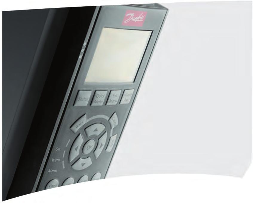
4 VLT HVAC Drive Programming Guide 1. How to Program 1. How to Program Local Control Panel How to operate the Graphical LCP (GLCP) The following instructions apply to the GLCP (LCP 10). The GLCP is divided into four functional groups: 1. Graphical display with status lines.. Menu keys and LEDs - for selecting mode, changing parameters and switching between display functions. 3. Navigation keys and lights (LEDs). 4. Operation keys and LEDs. Graphical display: The LCD display is backlit with a total of 6 alpha-numeric lines. All data is displayed on the LCP, which can show up to five operating variables while in [Status] mode. Display lines: a. Status line: Status messages displaying icons and graphics.1 b. Line 1-: Operator data lines displaying data and variables defined or chosen by the user. By pressing the [Status] key, up to one extra line can be added.1 c. Status line: Status messages displaying text.1 MG.11.C3. - VLT is a registered Danfoss trademark 3
 is shown.")
 shows up to 5 variables with related unit, regardless of status. In case of an alarm/warning, the warning is shown instead of the variables.")
5 1. How to Program VLT HVAC Drive Programming Guide 1 The display is divided into 3 sections: The top section (a) shows the status when in status mode or up to variables when not in status mode and in the case of an alarm/warning. The number of the active set-up (selected as the active set-up in par. 0-10) is shown. When programming in another set-up than the active set-up, the number of the set-up being programmed appears to the right in brackets. The middle section (b) shows up to 5 variables with related unit, regardless of status. In case of an alarm/warning, the warning is shown instead of the variables. It is possible to toggle between three status readout displays by pressing the [Status] key. Operating variables with different formatting are shown in each status screen - see below. Several values or measurements can be linked to each of the displayed operating variables. The values/measurements to be displayed can be defined via par. 0-0, 0-1, 0-, 0-3 and 0-4, which can be accessed via [QUICK MENU], "Q3 Function Set-ups", "Q3-1 General Settings", "Q3-13 Display Settings". Each value/measurement readout parameter selected in par. 0-0 to par. 0-4 has its own scale and number of digits after a possible decimal point. Larger numeric values are displayed with few digits after the decimal point. Ex.: Current readout 5.5 A; 15. A 105 A. Status display I: This readout state is standard after start-up or initialization. Use [INFO] to obtain information about the value/measurement linked to the displayed operating variables (1.1, 1., 1.3, and 3). See the operating variables shown in the display in this illustration. 1.1, 1. and 1.3 are shown in small size, while and 3 are shown in medium size BP Status display II: See the operating variables (1.1, 1., 1.3 and ) shown in the display in this illustration. In the example, Speed, Motor current, Motor power and Frequency are selected as variables in the first and second lines. 1.1, 1. and 1.3 are shown in small size, while is shown in large size BP MG.11.C3. - VLT is a registered Danfoss trademark

![Press [status] and [ ] for brighter display. Top section Middle section 130BP074.10 Bottom section LEDs: If certain threshold values are exceeded, the alarm and/or warning LED lights up.](/docs-images/93/112872976/images/6-1.jpg "A status and alarm text appear on the control panel. The On LED is activated when the adjustable frequency drive receives power from AC line voltage, a DC bus terminal or an external 4 V supply.")
6 VLT HVAC Drive Programming Guide 1. How to Program Status display III: This state displays the event and action of the smart logic control. For further information, see section Smart Logic Control. 1 The bottom section always shows the state of the adjustable frequency drive in status mode. Display Contrast Adjustment Press [status] and [ ] for darker display. Press [status] and [ ] for brighter display. Top section Middle section 130BP Bottom section LEDs: If certain threshold values are exceeded, the alarm and/or warning LED lights up. A status and alarm text appear on the control panel. The On LED is activated when the adjustable frequency drive receives power from AC line voltage, a DC bus terminal or an external 4 V supply. At the same time, the back light is on. Green LED/On: Control section is working. Yellow LED/Warn.: Indicates a warning. Flashing Red LED/Alarm: Indicates an alarm. 130BP GLCP keys Menu keys The menu keys are divided into functions. The keys below the display and LEDs are used for parameter set-up, including display indication selection during normal operation. 130BP MG.11.C3. - VLT is a registered Danfoss trademark 5
7 1. How to Program VLT HVAC Drive Programming Guide 1 [Status] indicates the status of the adjustable frequency drive and/or the motor. Three different readouts can be chosen by pressing the [Status] key: 5-line readouts, 4-line readouts or smart logic control. Use [Status] for selecting the mode of display or for changing back to display mode from either the quick menu mode, the main menu mode or alarm mode. The [Status] key can also be used to toggle between single and double readout modes. [Quick Menu] allows for the quick set-up of the adjustable frequency drive. The most common HVAC functions can be programmed here. The [Quick Menu] consists of: - My Personal Menu - Quick Set-up - Function Set-up - Changes Made - Loggings The function set-up provides quick and easy access to all the parameters required for the majority of HVAC applications, including most VAV and CAV supply and return fans, cooling tower fans, primary, secondary and condenser water pumps and other pump, fan and compressor applications. Among other features, it also includes parameters for selecting which variables to display on the LCP, digital preset speeds, scaling of analog references, closed-loop single zone and multizone applications and specific functions related to fans, pumps and compressors. The quick menu parameters can be accessed immediately, unless a password has been created via par. 0-60, 0-61, 0-65 or It is possible to switch directly between quick menu mode and main menu mode. [Main Menu] is used for programming all parameters. The main menu parameters can be accessed immediately, unless a password has been created via par. 0-60, 0-61, 0-65 or For the majority of HVAC applications, it is not necessary to access the Main Menu parameters. Instead, the Quick Menu, Quick Set-up and Function Set-up provide the simplest and quickest access to the most commonly required parameters. It is possible to switch directly between main menu mode and quick menu mode. Parameter shortcut can be carried out by pressing down the [Main Menu] key for 3 seconds. The parameter shortcut allows direct access to any parameter. [Alarm Log] displays an Alarm list of the last five alarms (numbered A1-A5). For additional details on a particular alarm, use the arrow keys to navigate to the alarm number and press [OK]. Information is displayed about the condition of the adjustable frequency drive before it enters alarm mode. The alarm log button on the LCP allows access to both the alarm log and the maintenance log. 6 MG.11.C3. - VLT is a registered Danfoss trademark
![VLT HVAC Drive Programming Guide 1. How to Program [Back] reverts to the previous step or layer in the navigation structure.](/docs-images/93/112872976/images/8-0.jpg "[Cancel] the last change or command will be canceled as long as the display has not been changed. [Info] displays information about a command, parameter or function in any display window.")
8 VLT HVAC Drive Programming Guide 1. How to Program [Back] reverts to the previous step or layer in the navigation structure. [Cancel] the last change or command will be canceled as long as the display has not been changed. [Info] displays information about a command, parameter or function in any display window. [Info] provides detailed information when needed. Exit info mode by pressing either [Info], [Back] or [Cancel]. 1 Navigation Keys The four navigation arrows are used to navigate between the different choices available in [Quick Menu], [Main Menu] and [Alarm Log]. Use the keys to move the cursor. 130BT [OK] is used for choosing a parameter marked by the cursor and for enabling the change of a parameter. Operation keys for local control are found at the bottom of the control panel. 130BP [Hand On] enables control of the adjustable frequency drive via the GLCP. [Hand on] also starts the motor and makes it possible to enter the motor speed data by using the arrow keys. The key can be selected as Enable [1] or Disable [0] via par [Hand on] key on LCP. The following control signals will still be active when [Hand on] is activated: [Hand on] - [Off] - [Auto on] Reset Coasting stop inverse Reversing MG.11.C3. - VLT is a registered Danfoss trademark 7
9 1. How to Program VLT HVAC Drive Programming Guide 1 Set-up select lsb - Set-up select msb Stop command from serial communication Quick stop DC brake NOTE External stop signals activated by using control signals or a serial bus will override a start command via the LCP. [Off] stops the connected motor. The key can be selected as Enable [1] or Disable [0] via par [Off] key on LCP. If no external stop function is selected and the [Off] key is inactive, the motor can only be stopped by disconnecting the line power supply. [Auto On] enables the adjustable frequency drive to be controlled via the control terminals and/or serial communication. When a start signal is applied to the control terminals and/or the bus, the adjustable frequency drive will start. The key can be selected as Enable [1] or Disable [0] via par. 0-4 [Auto on] key on LCP. NOTE An active HAND-OFF-AUTO signal via the digital inputs has higher priority than the control keys [Hand on] [Auto on]. [Reset] is used for resetting the adjustable frequency drive after an alarm (trip). It can be selected as Enable [1] or Disable [0] via par Reset Keys on LCP. The parameter shortcut can be carried out by holding down the [Main Menu] key for 3 seconds. The parameter shortcut allows direct access to any parameter. 8 MG.11.C3. - VLT is a registered Danfoss trademark
10 VLT HVAC Drive Programming Guide 1. How to Program How to operate the Numeric LCP (NLCP) The following instructions are valid for the NLCP (LCP 101). The control panel is divided into four functional groups: 1. Numeric display.. Menu key and LEDs - changing parameters and switching between display functions. 3. Navigation keys and LEDs. 4. Operation keys and LEDs. 1 NOTE Parameter copy is not possible with the Numeric Local Control Panel (LCP101). Select one of the following modes: Status Mode: Displays the status of the adjustable frequency drive or the motor. If an alarm occurs, the NLCP automatically switches to status mode. A number of alarms can be displayed. Quick Set-up or Main Menu Mode: Display parameters and parameter settings. 1.1: Numerical LCP (NLCP) 1.: Status display example 130BP BP : Alarm display example LEDs: Green LED/On: Indicates if control section is on. Yellow LED/Wrn.: Indicates a warning. Flashing red LED/Alarm: Indicates an alarm. Menu key [Menu] Select one of the following modes: Status Quick Set-up Main Menu Main Menu is used for programming all parameters. The parameters can be accessed immediately unless a password has been created via par. 0-60, 0-61, 0-65 or Quick Set-up is used to set up the adjustable frequency drive using only the most essential parameters. The parameter values can be changed using the up/down arrows when the value is flashing. Select the Main Menu by pressing the [Menu] key a number of times until the Main Menu LED is lit. Select the parameter group [xx- ] and press [OK]. MG.11.C3. - VLT is a registered Danfoss trademark 9
![1. How to Program VLT HVAC Drive Programming Guide 1 Select the parameter [ -xx] and press [OK]. If the parameter is an array parameter, select the array number and press [OK].](/docs-images/93/112872976/images/11-0.jpg "Select the desired data value and press [OK]. Navigation Keys [Back] for stepping backwards Arrow [ ] [ ] keys are used for navigating between parameter groups, parameters and within parameters.")
11 1. How to Program VLT HVAC Drive Programming Guide 1 Select the parameter [ -xx] and press [OK]. If the parameter is an array parameter, select the array number and press [OK]. Select the desired data value and press [OK]. Navigation Keys [Back] for stepping backwards Arrow [ ] [ ] keys are used for navigating between parameter groups, parameters and within parameters. [OK] is used for choosing a parameter marked by the cursor and for enabling the change of a parameter. 130BP : Display example Operation Keys Keys for local control are found at the bottom of the control panel. 130BP : Operation keys of the Numerical CP (NLCP) [Hand on] enables control of the adjustable frequency drive via the LCP. [Hand on] also starts the motor and makes it possible to enter the motor speed data by means of the arrow keys. The key can be selected as Enable [1] or Disable [0] via par [Hand on] Key on LCP. External stop signals activated by means of control signals or a serial bus will override a start command via the LCP. The following control signals will still be active when [Hand on] is activated: [Hand on] - [Off] - [Auto on] Reset Coasting stop inverse Reversing Set-up select lsb - Set-up select msb Stop command from serial communication Quick stop DC brake [Off] stops the connected motor. The key can be selected as Enable [1] or Disable [0] via par [Off] Key on LCP. 10 MG.11.C3. - VLT is a registered Danfoss trademark
12 VLT HVAC Drive Programming Guide 1. How to Program If no external stop function is selected and the [Off] key is inactive, the motor can be stopped by disconnecting the line power supply. [Auto on] enables the adjustable frequency drive to be controlled via the control terminals and/ or serial communication. When a start signal is applied to the control terminals and/or the bus, the adjustable frequency drive will start. The key can be selected as Enable [1] or Disable [0] via par. 0-4 [Auto on] Key on LCP. 1 NOTE An active HAND-OFF-AUTO signal via the digital inputs has higher priority than the control keys [Hand on] [Auto on]. [Reset] is used for resetting the adjustable frequency drive after an alarm (trip). It can be selected as Enable [1] or Disable [0] via par Reset Keys on LCP Quick Transfer of Parameter Settings between Multiple Adjustable Frequency Drives Once the set-up of an adjustable frequency drive is complete, we recommend that you store the data in the LCP or on a PC via the MCT 10 Set-up Software tool. Data storage in LCP: 1. Go to par LCP Copy. Press the [OK] key. 3. Select All to LCP 4. Press the [OK] key. All the parameter settings are now being stored in the LCP as indicated by the progress bar. When 100% is reached, press [OK]. You can now connect the LCP to another adjustable frequency drive and copy the parameter settings to this adjustable frequency drive as well. MG.11.C3. - VLT is a registered Danfoss trademark 11
13 1. How to Program VLT HVAC Drive Programming Guide 1 Data transfer from LCP to adjustable frequency drive: 1. Go to par LCP Copy. Press the [OK] key. 3. Select All from LCP. 4. Press the [OK] key. The parameter settings stored in the LCP are now transferred to the adjustable frequency drive as indicated by the progress bar. When 100% is reached, press [OK] Parameter Set-up The adjustable frequency drive can be used for practically all assignments, thus offering a significant number of parameters. The series offers a choice between two programming modes - a Quick Menu mode and a Main Menu mode. The latter provides access to all parameters. The former takes the user through a few parameters making it possible to program the majority of HVAC applications. Regardless of the mode of programming, you can change a parameter both in quick menu mode and in main menu mode Quick Menu Mode Parameter Data The graphical display (GLCP) provides access to all parameters listed under the quick menus. The numeric display (NLCP) only provides access to the Quick Set-up parameters. To set parameters using the [Quick Menu] button, enter or change parameter data or settings in accordance with the following procedure: 1. Press the Quick Menu button. Use the [ ] and [ ] buttons to find the parameter you want to change. 3. Press [OK] 4. Use [ ] and [ ] buttons to select the correct parameter setting. 5. Press [OK] 6. To move to a different digit within a parameter setting, use the [ ] and [ ] buttons. 7. Highlighted area indicates digit selected for change. 8. Press [Cancel] button to disregard change, or press [OK] to accept change and enter the new setting. Example of Changing Parameter Data Assume parameter -60, Broken Belt Function is set to [Off]. However, you should still monitor the fan belt condition - non-broken or broken - according to the following procedure: 1. Press the Quick Menu key.. Choose Function Set-ups with the [ ] button. 3. Press [OK] 4. Choose Application Settings with the [ ] button. 5. Press [OK] 6. Press [OK] again for fan functions. 7. Choose the broken belt function by pressing [OK]. 8. With [ ] button, choose [] Trip. The adjustable frequency drive will now trip if a broken fan belt is detected. 1 MG.11.C3. - VLT is a registered Danfoss trademark
14 VLT HVAC Drive Programming Guide 1. How to Program Select [My Personal Menu] to display only the parameters that have been pre-selected and programmed as personal parameters. For example, an AHU or pump OEM may have pre-programmed these to be in My Personal Menu during factory commissioning to make on-site commissioning/ fine tuning simpler. These parameters are selected in par. 0-5 Personal Menu. Up to 0 different parameters can be programmed in this menu. 1 If [No Operation] is selected in par. Terminal 7 Digital Input, no connection to +4 V on terminal 7 is necessary to enable start. If [Coast Inverse] (factory default value) is selected in par. Terminal 7 Digital Input, a connection to +4 V is necessary to enable start. Select [Changes Made] to get information about: The last 10 changes. Use the up/down navigation keys to scroll between the last 10 changed parameters. The changes made since default setting. Select [Loggings] to get information about the display line readouts. The information is shown in graphs. Only display parameters selected in par. 0-0 and par. 0-4 can be viewed. It is possible to store up to 10 samples in the memory for later reference. Efficient Parameter Set-up for HVAC Applications The parameters can easily be set up for the vast majority of the HVAC applications only by using the [Quick Set-up] option. After pressing [Quick Menu], the different areas in the quick menu are listed. See also illustration 6.1 below and tables Q3-1 to Q3-4 in the following Function Set-ups section. Example of using the Quick Set-up option Assume you want to set the ramp-down time to 100 seconds! 1. Press [Quick Set-up]. The first par Language in Quick Set-up appears. Press [ ] repeatedly until par. 3-4 Ramp 1 Ramp-down Time appears with the default setting of 0 seconds 3. Press [OK] 4. Use the [ ] button to highlight the 3rd digit before the comma. 5. Change '0' to '1' by using the [ ] button. 6. Use the [ ] button to highlight the digit ''. 7. Change '' to '0' with the [ ] button. 8. Press [OK] The new ramp-down time is now set to 100 seconds. It is recommended to do the set-up in the order listed. NOTE A complete description of the function is found in the parameter sections of this Instruction Manual. MG.11.C3. - VLT is a registered Danfoss trademark 13
 quick menu parameters are shown in the table below.")
15 1. How to Program VLT HVAC Drive Programming Guide 1 The QUICK Set-up menu gives access to the 1 most important set-up parameters of the drive. After programming, the drive will, in most cases, be ready for operation. The 1 (see footnote) quick menu parameters are shown in the table below. A complete description of the function is given in the parameter sections of this manual. 1.6: Quick Menu view. Par. Designation [Units] 0-01 Language 1-0 Motor Power [kw] 1-1 Motor Power* [HP] 1- Motor Voltage [V] 1-3 Motor Frequency [Hz] 1-4 Motor Current [A] 1-5 Motor Nominal Speed [RPM] 3-41 Ramp 1 Ramp-up Time [s] 3-4 Ramp 1 Ramp-down Time [s] 4-11 Motor Speed Low Limit [RPM] 4-1 Motor Speed Low Limit* [Hz] 4-13 Motor Speed High Limit [RPM] 4-14 Motor Speed High Limit* [Hz] 3-11 Jog Speed* [Hz] 5-1 Terminal 7 Digital Input 5-40 Function Relay *The display showing depends on choices made in parameter 0-0 and The default setting of parameters 0-0 and 0-03 depends upon the region of the world to which the adjustable frequency drive has been supplied, but it can be re-programmed as needed. 1.1: Quick Set-up parameters Parameters for Quick Set-up function: 0-01 Language Defines the language to be used in the display. The adjustable frequency drive can be delivered with 4 different language packages. English and German are included in all packages. English cannot be erased or manipulated. [0] * English UK Part of Language packages 1-4 [1] German Part of Language packages 1-4 [] French Part of Language package 1 [3] Danish Part of Language package 1 [4] Spanish Part of Language package 1 [5] Italian Part of Language package 1 [6] Swedish Part of Language package 1 14 MG.11.C3. - VLT is a registered Danfoss trademark
16 VLT HVAC Drive Programming Guide 1. How to Program [7] Dutch Part of Language package 1 [10] Chinese Language package 1 [0] Finnish Part of Language package 1 [] English US Part of Language package 4 [7] Greek Part of Language package 4 [8] Portuguese Part of Language package 4 [36] Slovenian Part of Language package 3 [39] Korean Part of Language package [40] Japanese Part of Language package [41] Turkish Part of Language package 4 [4] Traditional Chinese Part of Language package [43] Bulgarian Part of Language package 3 [44] Serbian Part of Language package 3 [45] Romanian Part of Language package 3 [46] Hungarian Part of Language package 3 [47] Czech Part of Language package 3 [48] Polish Part of Language package 4 [49] Russian Part of Language package 3 [50] Thai Part of Language package [51] Bahasa Indonesian Part of Language package 1-0 Motor Power [kw] Size related* 500 [ hp [ kw]] Enter the nominal motor power (in kw) according to the motor nameplate data. The default value corresponds to the nominal rated output of the unit. This parameter cannot be adjusted while the motor is running. Depending on the choices made in par Regional Settings, either par. 1-0 or par. 1-1Motor Power is made invisible. 1-1 Motor Power [HP] Size related* nameplate data. The default value corresponds to the nominal [ hp] Enter the nominal motor power (in HP) according to the motor rated output of the unit. MG.11.C3. - VLT is a registered Danfoss trademark 15
17 1. How to Program VLT HVAC Drive Programming Guide 1 This parameter cannot be adjusted while the motor is running. Depending on the choices made in par Regional Settings, either par. 1-0 or par. 1-1Motor Power is made invisible. 1- Motor Voltage Size relatedplate data. The default value corresponds to the nominal rated [10-1,000 V] Enter the nominal motor voltage according to the motor name- output of the unit. This parameter cannot be adjusted while the motor is running. 1-3 Motor Frequency Size related* data. For 87 Hz operation with 30/400 V motors, set the name- [ Hz] Select the motor frequency value from the motor nameplate plate data for 30 V/50 Hz. Adapt par Motor Speed High Limit [RPM) and par Maximum Reference to the 87 Hz application. This parameter cannot be adjusted while the motor is running. 1-4 Motor Current Size relatedplate data. This data is used for calculating motor torque, motor [0.1-10,000 A] Enter the nominal motor current value from the motor name- thermal protection, etc. This parameter cannot be adjusted while the motor is running. 1-5 Motor Nominal Speed Size related* data. This data is used for calculating automatic motor com- [100-60,000 rpm] Enter the nominal motor speed value from the motor nameplate pensations. This parameter cannot be adjusted while the motor is running Jog Speed [Hz] Size related* frequency drive is running when the jog function is activated. [ Hz] The jog speed is a fixed output speed at which the adjustable See also par MG.11.C3. - VLT is a registered Danfoss trademark
18 VLT HVAC Drive Programming Guide 1. How to Program 3-41 Ramp 1 Ramp-up Time 3 s* [ s] Enter the ramp-up time, i.e., the acceleration time from 0 rpm to the rated motor speed nm,n (par. 1-5). Choose a ramp-up time such that the output current does not exceed the current limit in par during ramping. Enter the ramp-up time, i.e., the acceleration time from 0 rpm to the rated motor speed nm,n (par. 1-5) par.3 41 = tacc nnorm par.1 5 ref rpm s Ramp 1 Ramp-down Time 3 s* [1-3,600 s] Enter the ramp-down time, i.e., the deceleration time from the rated motor speed nm,n (par. 1-5) to 0 rpm. Choose a rampdown time so that no overvoltage arises in the inverter due to regenerative operation of the motor, and so that the generated current does not exceed the current limit set in par See ramp-up time in par tdec nnorm par.1 5 par.3 4 = ref rpm s 4-11 Motor Speed Low Limit [RPM] Size related* Limit can be set to correspond to the manufacturer s recom- [0-60,000 rpm] Enter the minimum limit for motor speed. The Motor Speed Low mended minimum motor speed. The Motor Speed Low Limit must not exceed the setting in par Motor Speed High Limit [RPM]. MG.11.C3. - VLT is a registered Danfoss trademark 17
19 1. How to Program VLT HVAC Drive Programming Guide Motor Speed Low Limit [Hz] Size related* limit can be set to correspond to the minimum output frequency [ Hz] Enter the minimum limit for motor speed. The motor speed low of the motor shaft. The Motor Speed Low Limit must not exceed the setting in par Motor Speed High Limit [Hz] Motor Speed High Limit [RPM] Size related* High Limit can be set to correspond to the manufacturer s max- [0-60,000 rpm] Enter the maximum limit for motor speed. The Motor Speed imum rated motor speed. The Motor Speed High Limit must exceed the setting in par Motor Speed Low Limit [RPM]. Only par or 4-1 will be displayed depending on other parameters set in the Main Menu, and depending on default settings specific to global geographical locations. NOTE The output frequency value of the adjustable frequency drive must not exceed a value higher than 1/10 of the switching frequency Motor Speed High Limit [Hz] Size related* limit can be set to correspond to the manufacturer s recom- [ Hz] Enter the maximum limit for motor speed. The motor speed high mended maximum frequency of the motor shaft. The Motor Speed High Limit must exceed the setting in par. 4-1 Motor Speed Low Limit [Hz]. Only par or 4-1 will be displayed depending on other parameters set in the Main Menu, and depending on default settings specific to global geographical locations. NOTE Max. output frequency cannot exceed 10% of the inverter switching frequency (par ) Function Set-ups The function set-up provides quick and easy access to all the parameters required for the majority of HVAC applications, including most VAV and CAV supply and return fans, cooling tower fans, primary, secondary and condenser water pumps and other pump, fan and compressor applications. 18 MG.11.C3. - VLT is a registered Danfoss trademark


. 1.")

![10 130BT115.10 1.8: Step : Press the [Quick Menus] button](/docs-images/93/112872976/images/20-4.jpg "(quick menu choices appear). 1.")


20 VLT HVAC Drive Programming Guide 1. How to Program Example of how to access Function Set-up: 1 130BT BT : Step 1: Turn on the adjustable frequency drive (yellow LEDs). 1.11: Step 5: Use the up/down navigation keys to scroll down to, e.g., Analog Outputs. Press [OK]. 130BT BT : Step : Press the [Quick Menus] button (quick menu choices appear). 1.1: Step 6: Choose parameter 6-50 Terminal 4 Output. Press [OK]. 130BT BT : Step 3: Use the up/down navigation keys to scroll down to Function Set-ups. Press [OK]. 1.13: Step 7: Use the up/down navigation keys to select between the different choices. Press [OK]. 130BT : Step 4: Function Set-ups choices appear. Choose 03-1 General Settings. Press [OK]. MG.11.C3. - VLT is a registered Danfoss trademark 19
21 1. How to Program VLT HVAC Drive Programming Guide 1 The Function Set-up parameters are grouped in the following way: Q3-1 General Settings Q3-10 Adv. Motor Settings Q3-11 Analog Output Q3-1 Clock Settings Q3-13 Display Settings 1-90 Motor Thermal Protection 6-50 Terminal 4 Output 0-70 Set date and time 0-0 Display Line 1.1 Small 1-93 Thermistor Source 6-51 Terminal 4 Output max. scale 0-71 Date format 0-1 Display Line 1. Small 1-9 Automatic Motor Adaptation 6-5 Terminal 4 Output min. 0-7 Time format 0- Display Line 1.3 Small scale Switching Frequency 0-74 DST/Summertime 0-3 Display Line large 0-76 DST/Summertime start 0-4 Display Line 3 large 0-77 DST/Summertime end 0-37 Display Text Display Text 0-39 Display Text 3 Q3- Open-loop Settings Q3-0 Digital Reference Q3-1 Analog Reference 3-0 Minimum reference 3-0 Minimum reference 3-03 Maximum Reference 3-03 Maximum Reference 3-10 Preset reference 6-10 Terminal 53 low voltage 5-13 Terminal 9 digital input 6-11 Terminal 53 high voltage 5-14 Terminal 3 digital input 6-14 Terminal 53 low ref/feedb. value 5-15 Terminal 33 digital input 6-15 Terminal 53 high ref/feedb. value Q3-3 Closed-loop Settings Q3-30 Single Zone Int. S. Q3-31 Single Zone Ext. S Q3-3 Multi Zone / Adv Configuration mode 1-00 Configuration mode 1-00 Configuration mode 0-1 Reference/feedb unit 0-1 Reference/feedback 0-1 Reference/feedb unit 3-0 Minimum reference 3-0 Minimum reference 3-0 Minimum reference 3-03 Maximum Reference 3-03 Maximum Reference 3-03 Maximum Reference 6-4 Terminal 54 low ref/feedb value 6-10 Terminal 53 low voltage 3-15 Reference 1 source 6-5 Terminal 54 high ref/feedb value 6-11 Terminal 53 high voltage 3-16 Reference source 6-6 Terminal 54 Filter time constant 6-14 Terminal 53 low ref/feedb. value 0-00 Feedback 1 source 6-7 Terminal 54 live zero 6-15 Terminal 53 high ref/feedb. value 0-01 Feedback 1 conversion 6-00 Live zero timeout time 6-4 Terminal 54 low ref/feedb value 0-03 Feedback 1 source 6-01 Live zero timeout function 6-5 Terminal 54 high ref/feedb value 0-04 Feedback conversion 0-81 PID normal/inverse control 6-6 Terminal 54 Filter time constant 0-06 Feedback 3 source 0-8 PID start speed [RPM] 6-7 Terminal 54 live zero 0-07 Feed back 3 conversion 0-1 Setpoint Live zero timeout time 6-10 Terminal 53 low voltage 0-93 PID proportional gain 6-01 Live zero timeout function 6-11 Terminal 53 high voltage 0-94 PID integral time 0-81 PID normal/inverse control 6-14 Terminal 53 low ref/feedb. value 0-8 PID start speed [RPM] 0-93 PID proportional gain 0-94 PID integral time 4-56 Warning feedback low 4-57 Warning feedback high 0-0 Feedback function 0-1 Setpoint 1 0- Setpoint 0 MG.11.C3. - VLT is a registered Danfoss trademark
22 VLT HVAC Drive Programming Guide 1. How to Program Q3-4 Application Settings Q3-40 Fan Functions Q3-41 Pump Functions Q3-4 Compressor Functions -60 Broken belt function -0 Low power auto set-up 1-03 Torque characteristics -61 broken belt torque -1 Low power detection 1-71 Start delay 1-6 Broken belt delay - Low speed detection -75 Short cycle protection 4-64 Semi-auto bypass set-up -3 No-flow function -76 Interval between starts 1-03 Torque characteristics -4 No-flow delay -77 Minimum run time - Low speed detection -40 Minimum run time 5-01 Terminal 7 mode -3 No-flow function -41 Minimum sleep time 5-0 Terminal 9 mode -4 No-flow delay -4 Wake-up speed 5-1 Terminal 7 digital input -40 Minimum run time -6 Dry pump function 5-13 Terminal 9 digital input -41 Minimum sleep time -7 Dry pump delay 5-40 Function relay -4 Wake-up speed 1-03 Torque characteristics 1-73 Flying start -10 Brake function 1-73 Flying start -17 Overvoltage control 1-73 Flying start 1-71 Start delay 1-80 Function at stop -00 DC hold/preheat 4-10 Current motor speed direction See also VLT HVAC Drive Programming Guide for a detailed description of the function set-ups parameter groups. MG.11.C3. - VLT is a registered Danfoss trademark 1
![1. How to Program VLT HVAC Drive Programming Guide 1 1.1.7. Main Menu Mode Select Main Menu mode by pressing the [Main Menu] key. The readout below appears on the display.](/docs-images/93/112872976/images/23-0.jpg "The middle and bottom sections on the display show a list of parameter groups that can be chosen by toggling the up and down buttons.")
 indicates the parameter group number. All parameters can be changed in the main menu. However, depending on the choice of configuration (par.")
23 1. How to Program VLT HVAC Drive Programming Guide Main Menu Mode Select Main Menu mode by pressing the [Main Menu] key. The readout below appears on the display. The middle and bottom sections on the display show a list of parameter groups that can be chosen by toggling the up and down buttons. Each parameter has a name and number that remain the same regardless of the programming mode. In main menu mode, the parameters are divided into groups. The first digit of the parameter number (from the left) indicates the parameter group number. All parameters can be changed in the main menu. However, depending on the choice of configuration (par. 1-00), some parameters can be hidden Parameter Selection In main menu mode, the parameters are divided into groups. You select a parameter group by using the navigation keys. The following parameter groups are accessible: Group no. Parameter group: 0 Operation/Display 1 Load/Motor Brakes 3 References/Ramps 4 Limits/Warnings 5 Digital In/Out 6 Analog In/Out 8 Comm. and Options 9 Profibus 10 CAN ser. com. bus 11 LonWorks 13 Smart Logic 14 Special Functions 15 FC Information 16 Data Readouts 18 Data Readouts 0 Drive Closed-loop 1 Ext. Closed-loop Application Functions 3 Time-based Functions 5 Cascade Controller 6 Analog I/O Option MCB 109 After selecting a parameter group, choose a parameter using the navigation keys. The middle section on the display shows the parameter number and name, as well as the selected parameter value Changing Data The procedure for changing data is the same whether you select a parameter in the quick menu or main menu mode. Press [OK] to change the selected parameter. MG.11.C3. - VLT is a registered Danfoss trademark

![Place the cursor on the value you want to save and press [OK]. 1.1.11.](/docs-images/93/112872976/images/24-1.jpg "Changing a Group of Numeric Data Values If the chosen parameter represents a numeric data value, change the chosen data value by means of the [ ] [ ] navigation keys as well as the [ ] [ ] navigation")
24 VLT HVAC Drive Programming Guide 1. How to Program The procedure for changing data depends on whether the selected parameter represents a numerical data value or a text value Changing a Text Value 1 If the selected parameter is a text value, change the text value by means of the [ ] [ ] navigation keys. The up key increases the value, and the down key decreases the value. Place the cursor on the value you want to save and press [OK] Changing a Group of Numeric Data Values If the chosen parameter represents a numeric data value, change the chosen data value by means of the [ ] [ ] navigation keys as well as the [ ] [ ] navigation keys. Use the [ ] [ ] navigation keys to move the cursor horizontally. Use the [ ] [ ] navigation keys to change the data value. The up key increases the data value, and the down key reduces the data value. Place the cursor on the value you want to save and press [OK] Changing a Data Value,Step-by-Step Certain parameters can be changed step-by-step or by an infinite number of variables. This applies to Motor Power (par. 1-0), Motor Voltage (par. 1-) and Motor Frequency (par. 1-3). The parameters are changed both as a group of numeric data values and as numeric data values using an infinite number of variables Readout and Programming of Indexed Parameters Parameters are indexed when placed in a rolling stack. Par to contain a fault log that can be read out. Choose a parameter, press [OK], and use the up/down navigation keys to scroll through the value log. Use par as another example: Choose the parameter, press [OK], and use the up/down navigation keys to scroll through the indexed values. To change the parameter value, select the indexed value and press [OK]. Change the value by using the up/down keys. Press [OK] to accept the new setting. Press [CANCEL] to abort. Press [Back] to leave the parameter. MG.11.C3. - VLT is a registered Danfoss trademark 3
25 1. How to Program VLT HVAC Drive Programming Guide Initialization to Default Settings Initialize the adjustable frequency drive using default settings in two ways: Recommended initialization (via par. 14-) 1. Select par Press [OK] 3. Select Initialization 4. Press [OK] 5. Cut off the line power supply and wait until the display turns off. 6. Reconnect the line power supply - the adjustable frequency drive is now reset. 7. Change par. 14- back to Normal Operation. NOTE Keeps parameters selected in Personal Menu with default factory setting. Par. 14- initializes everything except: RFI Protocol 8-31 Address 8-3 Baud Rate 8-35 Minimum Response Delay 8-36 Max Response Delay 8-37 Max Inter-char Delay to Operating data 15-0 to 15- Historical log to 15-3 Fault log Manual initialization 1. Disconnect from the power supply and wait until the display turns off. a. Press [Status] - [Main Menu] - [OK] at the same time the LCP 10, Graphical Display is powering up. b. Press [Menu] while the LCP 101, Numerical Display is powering up. 3. Release the keys after 5 s. 4. The adjustable frequency drive is now programmed according to default settings. This procedure initializes all except: Operating Hours Power-ups Overtemps Overvolts NOTE When you carry out manual initialization, you also reset serial communication, RFI filter settings (par ) and fault log settings. Removes parameters selected in Personal Menu. 4 MG.11.C3. - VLT is a registered Danfoss trademark
26 VLT HVAC Drive Programming Guide 1. How to Program NOTE After initialization and power cycling, the display will not show any information until after a couple of minutes. 1 MG.11.C3. - VLT is a registered Danfoss trademark 5
27 . Parameter Description VLT HVAC Drive Programming Guide 6 MG.11.C3. - VLT is a registered Danfoss trademark
28 VLT HVAC Drive Programming Guide. Parameter Description. Parameter Description.1. Parameter Selection Parameters for VLT HVAC Drive FC 10 are grouped into various parameter groups to easily select the correct parameters for optimized operation of the adjustable frequency drive. The vast majority of HVAC applications can be programmed using the Quick Menu button and selecting the parameters under Quick Set-up and Function Set-ups. Descriptions and default settings of parameters may be found under the section Parameter Lists at the back of this manual. 0-xx Operation/Display 1-xx Load/Motor -xx Brakes 3-xx Reference/Ramps 4-xx Limits/ Warnings 5-xx Digital In/Out 6-xx Analog In/Out 8-xx Comm. and Options 9-xx Profibus 10-xx CAN Ser. Com. Bus 11-xx LonWorks 13-xx Smart Logic 14-xx Special Functions 15-xx FC Information 16-xx Data Readouts 18-xx Data Readouts 0-xx FC Closed-loop 1-xx Ext. Closed-loop -xx Application Functions 3-xx Timed Actions 4-xx Fire Mode 5-xx Cascade Controller 6-xx Analog I/O Option MCB 109 MG.11.C3. - VLT is a registered Danfoss trademark 7
29 . Parameter Description VLT HVAC Drive Programming Guide.. Main Menu - Operation and Display - Group * Operation / Display Parameters related to the fundamental functions of the adjustable frequency drive, function of the LCP buttons and configuration of the LCP display * Basic Settings Parameter group for basic adjustable frequency drive settings Language Defines the language to be used in the display. The adjustable frequency drive can be delivered with 4 different language packages. English and German are included in all packages. English cannot be erased or manipulated. [0] * English UK Part of Language packages 1-4 [1] German Part of Language packages 1-4 [] French Part of Language package 1 [3] Danish Part of Language package 1 [4] Spanish Part of Language package 1 [5] Italian Part of Language package 1 [6] Swedish Part of Language package 1 [7] Dutch Part of Language package 1 [10] Chinese Language package [0] Finnish Part of Language package 1 [] English US Part of Language package 4 [7] Greek Part of Language package 4 [8] Portuguese Part of Language package 4 [36] Slovenian Part of Language package 3 [39] Korean Part of Language package [40] Japanese Part of Language package [41] Turkish Part of Language package 4 [4] Traditional Chinese Part of Language package [43] Bulgarian Part of Language package 3 [44] Serbian Part of Language package 3 8 MG.11.C3. - VLT is a registered Danfoss trademark
30 VLT HVAC Drive Programming Guide. Parameter Description [45] Romanian Part of Language package 3 [46] Hungarian Part of Language package 3 [47] Czech Part of Language package 3 [48] Polish Part of Language package 4 [49] Russian Part of Language package 3 [50] Thai Part of Language package [51] Bahasa Indonesian Part of Language package 0-0 Motor Speed Unit This parameter cannot be adjusted while the motor is running. The display showing depends on settings in parameter 0-0 and The default setting of parameters 0-0 and 0-03 depends on which region of the world the adjustable frequency drive is supplied to, but can be re-programmed as required. NOTE Changing the Motor Speed Unit will reset certain parameters to their initial value. It is recommended to select the motor speed unit first before modifying other parameters. [0] * rpm Selects display of motor speed variables and parameters (i.e., references, feedbacks and limits) in terms of motor speed (rpm). [1] Hz Selects display of motor speed variables and parameters (i.e., references, feedbacks and limits) in terms of output frequency to the motor (Hz) Regional Settings This parameter cannot be adjusted while the motor is running. The display showing depends on settings in parameter 0-0 and The default setting of parameters 0-0 and 0-03 depends upon the region of the world to which the adjustable frequency drive has been supplied, but it can be re-programmed as needed. [0] * International Sets par. 1-0 Motor Power units to [kw] and the default value of par. 1-3 Motor Frequency [50 Hz]. [1] North America Sets par. 1-1 Motor Power units to HP and the default value of par. 1-3 Motor Frequency to 60 Hz. MG.11.C3. - VLT is a registered Danfoss trademark 9
31 . Parameter Description VLT HVAC Drive Programming Guide The setting not used is made invisible Operating State at Power-up (Hand) Select the operating mode upon reconnection of the adjustable frequency drive to line voltage after a power-down when operating in hand (local) mode. [0] * Resume Resumes operation of the adjustable frequency drive while maintaining the same local reference and the same start/stop condition (applied by [Hand On]/[Off] on the LCP, or hand start via a digital input as before the adjustable frequency drive was powered down). [1] Forced stop, ref=old Uses saved reference [1] to stop the adjustable frequency drive, while retaining the local speed reference prior to power-down in its memory. After the line voltage is reconnected, and after receiving a start command (using the LCP [Hand On] button or hand start command via a digital input), the adjustable frequency drive restarts and operates at the retained speed reference * Set-up Operations Define and control the individual parameter set-ups. The adjustable frequency drive has four parameter set-ups that can be programmed independently of each other. This makes the adjustable frequency drive very flexible and able to meet the requirements of many different HVAC system control schemes, often saving on the costs of external control equipment. For example, these can be used to program the adjustable frequency drive to operate according to one control scheme in one set-up (daytime operation, e.g.) and another control scheme in another set-up (night set back, e.g.). Alternatively, they can be used by an AHU or packaged unit OEM to identically program all their factory fitted adjustable frequency drives for different equipment models within a given range to have the same parameters; and then, during production/commissioning, simply select a specific set-up depending on which model within that range the adjustable frequency drive is installed. The active set-up (i.e., the set-up in which the adjustable frequency drive is currently operating) can be selected in parameter 0-10 and is displayed in the LCP. Using Multi set-up, it is possible to switch between set-ups with the adjustable frequency drive running or stopped, via digital input or serial communication commands (for night set back, e.g.). If it is necessary to change set-ups while running, ensure that parameter 0-1 is programmed as required. For the majority of HVAC applications, it will not be necessary to program parameter 0-1 even if change of set up while running is required; however, for very complex applications using the full flexibility of the multiple set-ups, it may be required. Using parameter 0-11, it is possible to edit parameters within any of the set-ups while continuing the adjustable frequency drive operation in its active set-up, which can be a different set-up than that being edited. Using parameter 0-51, it is possible to copy parameter settings between the set-ups to enable quicker commissioning if similar parameter settings are required in different set-ups. 30 MG.11.C3. - VLT is a registered Danfoss trademark
32 VLT HVAC Drive Programming Guide. Parameter Description 0-10 Active Set-up Select the set-up in which the adjustable frequency drive is to operate. Use par Set-up copy to copy a set-up to one or all other set-ups. To avoid conflicting settings of the same parameter within two different set-ups, link the set-ups together using par. 0-1 This Set-up Linked to. Stop the adjustable frequency drive before switching between set-ups where parameters marked not changeable during operation have different values. Parameters that are not changeable during operation are marked FALSE in the parameter lists in the section Parameter Lists. [0] Factory set-up Cannot be changed. It contains the Danfoss data set, and can be used as a data source when returning the other set-ups to a known state. [1] * Set-up 1 Set-up 1 [1] to Set-up 4 [4] are the four separate parameter set-ups within which all parameters can be programmed. [] Set-up [3] Set-up 3 [4] Set-up 4 [9] Multi set-up Is used for remote selection of set-ups using digital inputs and the serial communication port. This set-up uses the settings from par. 0-1 This option linked to Programming Set-up Select the set-up to be edited (i.e., programmed) during operation, either the active set-up or one of the inactive set-ups. The set-up number to be edited is displayed in the LCP in parentheses. [0] Factory set-up cannot be edited, but it is useful as a data source to return the other set-ups to a known state. [1] Set-up 1 Set-up 1 [1] to Set-up 4 [4] can be edited freely during operation, independently of the active set-up. [] Set-up [3] Set-up 3 [4] Set-up 4 [9] * Active Set-up (i.e., the set-up in which the adjustable frequency drive is operating) can also be edited during operation. Editing parameters in the chosen set-up would normally be done from the LCP, but it is also possible from any of the serial communication ports. MG.11.C3. - VLT is a registered Danfoss trademark 31

33 . Parameter Description VLT HVAC Drive Programming Guide 0-1 This Set-up Linked to This parameter only needs to be programmed if changing setups is required while the motor is running. It ensures that parameters that are 'not changeable during operation' have the same setting in all relevant set-ups. To enable conflict-free changes from one set-up to another while the adjustable frequency drive is running, link set-ups containing parameters that are not changeable during operation. The link will ensure the proper synchronization of the not changeable during operation parameter values when moving from one set-up to another during operation. Not changeable during operation parameters can be identified by the label FALSE in the parameter lists in the section Parameter Lists. The par. 0-1 link set-up feature is used when Multi set-up in par Active Set-up is selected. Multi set-up can be used to move from one set-up to another during operation (i.e., while the motor is running). Example: Use Multi set-up to shift from Set-up 1 to Set-up while the motor is running. Program parameters in Set-up 1 first, then ensure that Set-up 1 and Set-up are synchronized (or linked ). Synchronization can be performed in two ways: 1. Change the edit set-up to Set-up [] in par Edit Setup, and set par. 0-1 This Set-up Linked to to Set-up 1 [1]. This will start the linking (synchronizing) process. 130BP OR. While still in Set-up 1, using par. 0-50, copy Set-up 1 to Setup. Then set par. 0-1 to Set-up []. This will start the linking process. 3 MG.11.C3. - VLT is a registered Danfoss trademark

34 VLT HVAC Drive Programming Guide. Parameter Description 130BP After the link is complete, par Readout: Linked Set-ups will read {1,} in order to indicate that all not changeable during operation parameters are now the same in Set-up 1 and Set-up. If there are changes to a not changeable during operation parameter, such as in par 1-30 Stator Resistance (rs) in Set-up, they will also be changed automatically in Set-up 1. A switch between Set-up 1 and Set-up during operation is now possible. [1] * Set-up 1 [] Set-up [3] Set-up 3 [4] Set-up Readout: Linked Set-ups Array [5] 0* [0-55] View a list of all the set-ups linked by means of par. 0-1 This Set-up Linked to. The parameter has one index for each parameter set-up. The parameter value displayed for each index represents which set-ups are linked to that parameter set-up. Index LCP value 0 {0} 1 {1,} {1,} 3 {3} 4 {4}.1: Example: Set-up 1 and Set-up are linked 0-14 Readout: Prog. Set-ups/Channel AAA.AA A.AAA* [0 - FFF.FFF.FFF] View the setting of par Edit Set-up for each of the four different communication channels. When the number is dis- MG.11.C3. - VLT is a registered Danfoss trademark 33
35 . Parameter Description VLT HVAC Drive Programming Guide played in hex, as it is in the LCP, each number represents one channel. Numbers 1-4 represent a set-up number; F refers to the factory settings, A means active set-up. The channels are, from right to left: LCP, FC bus, USB, HPFB1.5. Example: The number AAAAAA1h means that the FC bus selected Set-up in par. 0-11, the LCP selected Set-up 1 and all others used the active set-up * LCP Display Define the variables displayed in the Graphical Local Control Panel. NOTE Please refer to parameters 0-37, 0-38 and 0-39 for information on how to write display texts 0-0 Display Line 1.1 Small Select a variable for display in line 1, left position. [0] None No display value selected [37] Display Text 1 Present control word [38] Display Text Enables an individual text string to be written, for display in the LCP or to be read via serial communication. [39] Display Text 3 Enables an individual text string to be written, for display in the LCP or to be read via serial communication. [89] Date and Time Readout [953] Profibus Warning Word [1005] Readout Transmit Error Counter [1006] Readout Receive Error Counter Displays the current date and time. Displays Profibus communication warnings. View the number of CAN control transmission errors since the last power-up. View the number of CAN control receipt errors since the last power-up. [1007] Readout Bus Off View the number of Bus Off events since the last power-up. Counter [1013] Warning Parameter View a DeviceNet-specific warning word. One separate bit is assigned to every warning. [1115] LON Warning Word Shows the LON-specific warnings. [1117] XIF Revision Shows the version of the external interface file of the Neuron C chip on the LON option. 34 MG.11.C3. - VLT is a registered Danfoss trademark
36 VLT HVAC Drive Programming Guide. Parameter Description [1118] LON Works Revision Shows the software version of the application program of the Neuron C chip on the LON option. [1501] Running Hours View the number of running hours of the motor. [150] kwh Counter View the line power consumption in kwh. [1600] Control Word View the control word sent from the adjustable frequency drive via the serial communication port in hex code. [1601] Reference [Unit] Total reference (sum of digital/analog/preset/bus/freeze ref./ catch up and slow-down) in selected unit. [160] * Reference % Total reference (sum of digital/analog/preset/bus/freeze ref./ catch up and slow-down) as a percentage. [1603] Status Word Present status word [1605] Main Actual Value [%] One or more warnings in a Hex code [1609] Custom Readout View the user-defined readouts as defined in par. 0-30, 0-31 and 0-3. [1610] Power [kw] Actual power consumed by the motor in kw. [1611] Power [hp] Actual power consumed by the motor in HP. [161] Motor Voltage Voltage supplied to the motor. [1613] Motor Frequency Motor frequency, i.e., the output frequency from the adjustable frequency drive in Hz. [1614] Motor Current Phase current of the motor measured as effective value. [1615] Frequency [%] Motor frequency, i.e., the output frequency from the adjustable frequency drive as a percentage. [1616] Torque [Nm] Present motor load as a percentage of the rated motor torque. [1617] Speed [RPM] Speed in rpm (revolutions per minute), i.e., the motor shaft speed in closed-loop based on the entered motor nameplate data, the output frequency and the load on the adjustable frequency drive. [1618] Motor Thermal Thermal load on the motor, calculated by the ETR function. See also parameter group 1-9* Motor Temperature. [16] Torque [%] Shows the actual torque produced as a percentage. [1630] DC Link Voltage Intermediate circuit voltage in the adjustable frequency drive. [163] Brake Energy/sec. Present braking energy transferred to an external brake resistor. Stated as an instantaneous value. [1633] Brake Energy/ min Braking energy transferred to an external brake resistor. The mean power is calculated continuously for the latest 10 seconds. MG.11.C3. - VLT is a registered Danfoss trademark 35
37 . Parameter Description VLT HVAC Drive Programming Guide [1634] Heatsink Temp. Present heatsink temperature of the adjustable frequency drive. The cut-out limit is 03 ± 9 F [95 ± 5 C]; cutting back in occurs at 158 ± 9 F [70 ± 5 C]. [1635] Thermal Drive Load Percentage load of the inverters [1636] Inv. Nom. Current Nominal current of the adjustable frequency drive. [1637] Inv. Max. Current Maximum current of the adjustable frequency drive. [1638] SL Control State State of the event executed by the control. [1639] Control Card Temp. Temperature of the control card. [1650] External Reference Sum of the external reference as a percentage, i.e., the sum of analog/pulse/bus. [165] Feedback [Unit] Reference value from programmed digital input(s). [1653] DigiPot Reference View the contribution of the digital potentiometer to the actual reference feedback. [1654] Feedback 1 [Unit] View the value of Feedback 1. See also par. 0-0*. [1655] Feedback [Unit] View the value of Feedback. See also par. 0-0*. [1656] Feedback 3 [Unit] View the value of Feedback 3. See also par. 0-0*. [1660] Digital Input Displays the status of the digital inputs. Signal low = 0; Signal high = 1. Regarding order, see par Bit 0 is at the extreme right. [1661] Terminal 53 Switch Setting of input terminal 53. Current = 0; Voltage = 1. Setting [166] Analog Input 53 Actual value at input 53 either as a reference or protection value. [1663] Terminal 54 Switch Setting of input terminal 54. Current = 0; Voltage = 1. Setting [1664] Analog Input 54 Actual value at input 54 either as reference or protection value. [1665] Analog Output 4 [ma] Actual value at output 4 in ma. Use par to select the variable to be represented by output 4. [1666] Digital Output [bin] Binary value of all digital outputs. [1667] Freq. Input #9 [Hz] Actual value of the frequency applied at terminal 9 as a pulse input. [1668] Freq. Input #33 [Hz] Actual value of the frequency applied at terminal 33 as a pulse input. [1669] Pulse Output #7 [Hz] [1670] Pulse Output #9 [Hz] [1671] Relay Output [bin] View the setting of all relays. Actual value of pulses applied to terminal 7 in digital output mode. Actual value of pulses applied to terminal 9 in digital output mode. 36 MG.11.C3. - VLT is a registered Danfoss trademark
38 VLT HVAC Drive Programming Guide. Parameter Description [167] Counter A View the present value of Counter A. [1673] Counter B View the present value of Counter B. [1675] Analog input X30/11 Actual value of the signal on input X30/11 (General Purpose I/ O Card. Option) [1676] Analog input X30/1 Actual value of the signal on input X30/1 (General Purpose I/ O Card. Optional) [1677] Analog output X30/8 [ma] Actual value at output X30/8 (General Purpose I/O Card. Optional) Use Par to select the variable to be shown. [1680] Ser. Com. Bus CTW 1 Control word (CTW) received from the bus master. [168] Ser. com. bus REF 1 Main reference value sent with control word via the serial communications network, such as from the BMS, PLC or another master controller, for example. [1684] Comm. Option STW Extended serial communication bus option status word. [1685] FC Port CTW 1 Control word (CTW) received from the bus master. [1686] FC Port REF 1 Status word (STW) sent to the bus master. [1690] Alarm Word One or more alarms in a Hex code (used for serial communications). [1691] Alarm Word One or more alarms in a Hex code (used for serial communications). [169] Warning Word One or more warnings in a Hex code (used for serial communications). [1693] Warning Word One or more warnings in a Hex code (used for serial communications). [1694] Ext. Status Word One or more status conditions in a Hex code (used for serial communications). [1695] Ext. Status Word One or more status conditions in a Hex code (used for serial communications). [1696] Maintenance Word The bits reflect the status for the programmed preventive maintenance events in parameter group 3-1*. [1830] Analog Input X4/1 Shows the value of the signal applied to terminal X4/1 on the analog I/O card. [1831] Analog Input X4/3 Shows the value of the signal applied to terminal X4/3 on the analog I/O card. [183] Analog Input X4/5 Shows the value of the signal applied to terminal X4/5 on the analog I/O card. [1833] Analog Out X4/7 [V] Shows the value of the signal applied to terminal X4/7 on the analog I/O card. MG.11.C3. - VLT is a registered Danfoss trademark 37
39 . Parameter Description VLT HVAC Drive Programming Guide [1834] Analog Out X4/9 [V] Shows the value of the signal applied to terminal X4/9 on the analog I/O card. [1835] Analog Out X4/11 [V] [117] Ext. 1 Reference [Unit] Shows the value of the signal applied to terminal X4/11 on the analog I/O card. The value of the reference for extended closed-loop controller 1. [118] Ext. 1 Feedback [Unit] The value of the feedback signal for extended closed-loop controller 1. [119] Ext. 1 Output [%] The value of the output from extended closed-loop controller 1. [137] Ext. Reference [Unit] The value of the reference for extended closed-loop controller. [138] Ext. Feedback [Unit] The value of the feedback signal for extended closed-loop controller. [139] Ext. Output [%] The value of the output from extended closed-loop controller. [157] Ext. 3 Reference [Unit] The value of the reference for extended closed-loop controller 3. [158] Ext. 3 Feedback [Unit] The value of the feedback signal for extended closed-loop controller 3. [159] Ext. Output [%] The value of the output from extended closed-loop controller 3. [30] No-Flow Power The calculated no-flow power for the actual operating speed. [580] Cascade Status Status for the operation of the cascade controller. [581] Pump Status Status for the operation of each individual pump controlled by the cascade controller. NOTE Please consult the VLT HVAC Drive Programming Guide, MG.11.Cx.yy for detailed information. 0-1 Display Line 1. Small Select a variable for display in line 1, middle position. [1614] * Motor Current [A] The options are the same as those listed for par. 0-0 Display Line 1.1 Small. 38 MG.11.C3. - VLT is a registered Danfoss trademark
40 VLT HVAC Drive Programming Guide. Parameter Description 0- Display Line 1.3 Small Select a variable for display in line 1, right position. [1610] * Power [kw] The options are the same as those listed for par. 0-0 Display Line 1.1 Small. 0-3 Display Line Large [1613] * Frequency [Hz] Select a variable for display in line. The options are the same as those listed for par. 0-0 Display Line 1.1 Small. 0-4 Display Line 3 Large [150] * Counter [kwh] Select a variable for display in line. The options are the same as those listed for par. 0-0 Display Line 1.1 Small. 0-5 My Personal Menu Array [0] [0-9999] Define up to 50 parameters to appear in the Q1 Personal Menu, accessible via the [Quick Menu] key on the LCP. The parameters will be displayed in the Q1 Personal Menu in the order they are programmed into this array parameter. Delete parameters by setting the value to For example, this can be used to provide quick, simple access to anywhere up to 0 parameters that require changing on a regular basis (for plant maintenance reasons, for example), or by an OEM to enable simple commissioning of their equipment...5. LCP Custom Readout, Par. 0-3* It is possible to customize the display elements for various purposes: *Custom Readout. Value proportional to speed (Linear, squared or cubed depending on unit selected in par. 0-30Custom Readout Unit ) *Display Text. text string stored in a parameter. MG.11.C3. - VLT is a registered Danfoss trademark 39
41 . Parameter Description VLT HVAC Drive Programming Guide Custom Readout The calculated value to be displayed is based on settings in par. 0-30,Custom Readout Unit, par. 0-31Custom Readout Min Value, (linear only), par. 0-3, Custom Readout Max Value, par. 4-13/4-14,Motor Speed High Limit and actual speed. The relation will depend on the type of unit selected in par. 0-30, Custom Readout Unit: Unit Type Dimensionless Speed Flow, volume Flow, mass Velocity Length Temperature Pressure Power Speed Relation Linear Quadratic Cubic 0-30 Custom Readout Unit Program a value to be shown in the display of the LCP. The value has a linear, squared or cubed relation to speed. This relation depends on the unit selected (see table above). The actual calculated value can be read in Custom Readout, par , and/ or shown in the display be selecting Custom Readout [16-09] in par , Display Line X.X Small (large). Dimensionless: [0] None [1] * % [5] PPM Speed: [10] 1/min [11] rpm 40 MG.11.C3. - VLT is a registered Danfoss trademark
42 VLT HVAC Drive Programming Guide. Parameter Description [1] Pulse/s Flow, volume: [0] l/s [1] l/min [] l/h [3] m 3 /s [4] m 3 /min [5] m 3 /h Flow, mass: [30] kg/s [31] kg/min [3] kg/h [33] ton/min [34] ton/h Velocity: [40] m/s [41] m/min Length: [45] m Temperature: [60] C Pressure: [70] mbar [71] bar [7] Pa [73] kpa [74] m WG Power: [80] kw Flow, volume: [10] GPM [11] gal/s [1] gal/min [13] gal/h [14] CFM [15] ft 3 /s [16] ft 3 /min [17] ft 3 /h Flow, mass: [130] lb/s [131] lb/min [13] lb/h MG.11.C3. - VLT is a registered Danfoss trademark 41
43 . Parameter Description VLT HVAC Drive Programming Guide Velocity: [140] ft/s [141] ft/min Length: [145] ft Temperature: [160] F Pressure: [170] psi [171] lb/in [17] in WG [173] ft WG Power: [180] HP 0-31 Custom Readout Min Value 0.00* [0 - par. 3] This parameter allows the choice of the min. value of the custom defined readout (occurs at zero speed). It is only possible to select a value different to 0 when selecting a linear unit in Custom Readout Unit, par For quadratic and cubic units, the minimum value will be Custom Readout Max Value * [Par ] This parameter sets the max value to be shown when the speed of the motor has reached the set value for Motor Speed High Limit, (par.4-13/4-14) Display Text 1 In this parameter, it is possible to write an individual text string for display in the LCP or to be read via serial communication. If to be displayed permanently select Display Text 1 in par. 0-0, 0-1, 0-, 0-3 or 0-4, Display Line XXX. Use the or buttons on the LCP to change a character. Use the and buttons to move the cursor. When a character is highlighted by the cursor, it can be changed. Use the or buttons on the LCP to change a character. A character can be inserted by placing the cursor between two characters and pressing or. 4 MG.11.C3. - VLT is a registered Danfoss trademark
44 VLT HVAC Drive Programming Guide. Parameter Description 0-38 Display Text In this parameter, it is possible to write an individual text string for display in the LCP or to be read via serial communication. If to be displayed permanently, select Display Text in par. 0-0, 0-1, 0-, 0-3 or 0-4, Display Line XXX. Use the or buttons on the LCP to change a character. Use the and buttons to move the cursor. When a character is highlighted by the cursor, this character can be changed. A character can be inserted by placing the cursor between two characters and pressing or Display Text 3 In this parameter, it is possible to write an individual text string for display in the LCP or to be read via serial communication. If to be displayed permanently, select Display Text 3 in par. 0-0, 0-1, 0-, 0-3 or 0-4, Display Line XXX. Use the or buttons on the LCP to change a character. Use the and buttons to move the cursor. When a character is highlighted by the cursor, this character can be changed. A character can be inserted by placing the cursor between two characters and pressing or...6. LCP Keypad, 0-4* Enable, disable and password protect individual keys on the LCP keypad [Hand on] Key on LCP [0] Disabled No function [1] * Enabled [Hand on] Key enabled. [] Password Avoid unauthorized start in hand mode. If par is included in the quick menu, then define the password in par Quick Menu Password. Otherwise, define the password in par Main Menu Password [Off] Key on LCP [0] Disabled No function [1] * Enabled [Off] Key is enabled. [] Password Avoid unauthorized stop. If par is included in the quick menu, then define the password in par Quick Menu Pass- MG.11.C3. - VLT is a registered Danfoss trademark 43
45 . Parameter Description VLT HVAC Drive Programming Guide word. Otherwise, define the password in par Main Menu Password. 0-4 [Auto on] Key on LCP [0] Disabled No function [1] * Enabled [Auto on] Key is enabled. [] Password Avoid unauthorized start in auto mode. If par. 0-4 is included in the quick menu, then define the password in par Quick Menu Password. Otherwise, define the password in par Main Menu Password [Reset] Key on LCP [0] Disabled No function [1] * Enabled [Reset] Key is enabled. [] Password Avoid unauthorized resetting. If par is included in the quick menu, then define the password in par Quick Menu Password. Otherwise, define the password in par Main Menu Password * Copy / Save Copy parameter settings between set-ups and to/from the LCP LCP Copy [0] * No copy No function [1] All to LCP Copies all parameters in all set-ups from the adjustable frequency drive memory to the LCP memory. For service purposes, copying all parameters to the LCP is recommended after commissioning. [] All from LCP Copies all parameters in all set-ups from the LCP memory to the adjustable frequency drive memory. [3] Size indep. from LCP Copies only the parameters that are independent of the motor size. The latter selection can be used to program several adjustable frequency drives with the same function without disturbing motor data that are already set. This parameter cannot be adjusted while the motor is running. 44 MG.11.C3. - VLT is a registered Danfoss trademark
46 VLT HVAC Drive Programming Guide. Parameter Description 0-51 Set-up Copy [0] * No copy No function [1] Copy to set-up 1 Copies all parameters in the present edit set-up (defined in par Edit Set-up) to Set-up 1. [] Copy to set-up Copies all parameters in the present edit set-up (defined in par Edit Set-up) to Set-up. [3] Copy to set-up 3 Copies all parameters in the present edit set-up (defined in par Edit Set-up) to Set-up 3. [4] Copy to set-up 4 Copies all parameters in the present edit set-up (defined in par Edit Set-up) to Set-up 4. [9] Copy to all Copies the parameters in the present set-up over to each of the set-ups 1 to * Password Define password access to menus Main Menu Password [100] * Define the password for access to the main menu via the [Main Menu] key. If par Access to Main Menu w/o Password is set to Full access [0], this parameter will be ignored Access to Main Menu w/o Password [0] * Full access Disables password defined in par Main Menu Password. [1] Read only Prevent unauthorized editing of main menu parameters. [] No access Prevent unauthorized viewing and editing of main menu parameters. [3] Bus: Read only Read only functions for parameters on serial communication bus and/ or FC standard bus. [4] Bus: No access No access to parameters is allowed via serial communication bus and/or FC standard bus. [5] All: Read only Read only function for parameters on LCP, serial communication bus or FC standard bus. [6] All: No access No access from LCP, serial communication bus or FC standard bus is allowed. If Full access [0] is selected then parameters 0-60, 0-65 and 0-66 will be ignored. MG.11.C3. - VLT is a registered Danfoss trademark 45
47 . Parameter Description VLT HVAC Drive Programming Guide 0-65 Personal Menu Password 00* [0-999] Define the password for access to the quick menu via the [Quick Menu] key. If par Access to Personal Menu w/o Password is set to Full access [0], this parameter will be ignored Access to Personal Menu w/o Password [0] * Full access Disables password defined in par Personal Menu Password. [1] Read only Prevents unauthorized editing of quick menu parameters. [] No access Prevents unauthorized viewing and editing of quick menu parameters. If par Access to Main Menu w/o Password is set to Full access [0] then this parameter will be ignored...9. Clock Settings, 0-7* Set the time and date of the internal clock. The internal clock can be used for such functions as: timed actions, energy log, trend analysis, date/time stamps on alarms, logged data and preventive maintenance. It is possible to program the clock for daylight saving time/summertime, weekly working days/ non-working days with 0 exceptions (holidays, etc.). Although the clock settings can be set via the LCP, they can also be set along with timed actions and preventative maintenance functions using the MCT10 software tool. NOTE The adjustable frequency drive has no backup of the clock function, and the set date/time will reset to default ( :00) after a power-down unless a real time clock module with backup is installed. If no module with backup is installed, it is recommended that the clock function only be used if the adjustable frequency drive is integrated into the BMS using serial communications, with the BMS maintaining synchronization of control equipment clock times. In par. 0-79, Clock Fault, it is possible to program for a warning in case the clock has not been set properly, e.g., after a power-down. NOTE If mounting an Analog I/O MCB 109 option card, a battery back-up of the date and time is included. 46 MG.11.C3. - VLT is a registered Danfoss trademark
48 VLT HVAC Drive Programming Guide. Parameter Description 0-70 Set Date and Time :00* [ : :59 ] Sets the date and time of the internal clock. The format to be used is set in par and Date Format Sets the date format to be used in the LCP. [0] YYYY-MM-DD [1] * DD-MM-YYYY [] MM/DD/YYYY 0-7 Time Format Sets the time format to be used in the LCP. [0] * 4 H [1] 1 H 0-73 Time Zone Offset 0.00* [ ] Sets the time zone offset to UTC; this is needed for automatic DST adjustment DST/Summertime Choose how Daylight Saving Time/Summertime should be handled. For manual DST/Summertime, enter the start date and end date in par and [0] * OFF [] Manual 0-76 DST/Summertime Start :00* [ : :59 ] Sets the date and time when Summertime/DST starts. The date is programmed in the format selected in par MG.11.C3. - VLT is a registered Danfoss trademark 47
49 . Parameter Description VLT HVAC Drive Programming Guide 0-77 DST/Summertime End :00* [ : :59 ] Sets the date and time when Summertime/DST ends. The date is programmed in the format selected in par Clock Fault Enables or disables the clock warning when the clock has not been set, or has been reset due to a power-down and no backup is installed. [0] * Disabled [1] Enabled 0-81 Working Days Array with 7 elements [0]-[6] displayed below parameter number in display. Press OK and step between elements by means of and buttons on the LCP. [0] No [1] * Yes Specify whether each weekday is a workday or a non-workday. First element of the array is Monday. The workdays are used for timed actions. 0-8 Additional Working Days Array with 5 elements [0]-[4] displayed below parameter number in display. Press OK and step between elements by means of and buttons on the LCP. 0* [0-4] Defines dates for additional working days that normally would be non-working days according to par Working Days Additional Non-Working Days Array with 15 elements [0]-[14] displayed below parameter number in display. Press OK and step between elements by means of and buttons on the LCP. 0* [0-14] Defines dates for additional non-working days that normally would be working days according to par Working Days. 48 MG.11.C3. - VLT is a registered Danfoss trademark
50 VLT HVAC Drive Programming Guide. Parameter Description 0-89 Date and Time Readout Displays the current date and time. The date and time is updated continuously. The clock will not begin counting until a setting different from default has been made in par MG.11.C3. - VLT is a registered Danfoss trademark 49
51 . Parameter Description VLT HVAC Drive Programming Guide.3. Main Menu - Load and Motor - Group General Settings, 1-0* Define whether the adjustable frequency drive operates in open-loop or closed-loop Configuration Mode [0] * Open-loop Motor speed is determined by applying a speed reference or by setting desired speed when in hand mode. Open-loop is also used if the adjustable frequency drive is part of a closed-loop control system based on an external PID controller providing a speed reference signal as output. [3] Closed-loop Motor speed will be determined by a reference from the built-in PID controller varying the motor speed as part of a closed-loop control process (e.g., constant pressure or flow). The PID controller must be configured in par. 0-**, Drive Closed-loop or via the function set-ups accessed by pressing the [Quick Menus] button. This parameter cannot be changed while the motor is running. NOTE When set for closed-loop, the commands reversing and start reversing will not reverse the direction of the motor Torque Characteristics [0] Compressor [1] Variable torque [] Auto energy optim. compressor [3] * Auto Energy Optim. VT Compressor [0]: For speed control of screw and scroll compressors. Provides a voltage that is optimized for a constant torque load characteristic of the motor in the entire range down to 15 Hz. Variable Torque [1]: For speed control of centrifugal pumps and fans. Also to be used when controlling more than one motor from the same adjustable frequency drive (multiple condenser fans or cooling tower fans, for example). Provides a voltage that is optimized for a squared torque load characteristic of the motor. 50 MG.11.C3. - VLT is a registered Danfoss trademark
52 VLT HVAC Drive Programming Guide. Parameter Description Auto Energy Optimization Compressor []: For optimum energy and efficient speed control of screw and scroll compressors. Provides a voltage that is optimized for a constant torque load characteristic of the motor in the entire range down to 15 Hz. In addition, the AEO feature will adapt the voltage exactly to the current load situation, thereby reducing energy consumption and audible noise from the motor. To obtain optimal performance, the motor power factor cos-phi must be set correctly. This value is set in par , Motor cos-phi. The parameter has a default value that is automatically adjusted when the motor data is programmed. These settings will typically ensure optimum motor voltage, but if the motor power factor cos-phi requires tuning, an AMA function can be carried out using par. 1-9, Automatic Motor Adaptation (AMA). It is very rarely necessary to adjust the motor power factor parameter manually. Auto Energy Optimization VT [3]: For optimum energy and efficient speed control of centrifugal pumps and fans. Provides a voltage that is optimized for a squared torque load characteristic of the motor. In addition, the AEO feature will adapt the voltage exactly to the current load situation, thereby reducing energy consumption and audible noise from the motor. To obtain optimal performance, the motor power factor cos-phi must be set correctly. This value is set in par , Motor cos-phi. The parameter has a default value and is automatically adjusted when the motor data is programmed. These settings will typically ensure optimum motor voltage, but if the motor power factor cosphi requires tuning, an AMA function can be carried out using par. 1-9, Automatic Motor Adaptation (AMA). It is very rarely necessary to adjust the motor power factor parameter manually * Motor Data Parameter group 1-* comprises input data from the nameplate on the connected motor. Parameters in parameter group 1-* cannot be adjusted while the motor is running. NOTE Changing the value of these parameters affects the setting of other parameters. 1-0 Motor Power [kw] Size related* 500 [ hp [ kw]] Enter the nominal motor power (in kw) according to the motor nameplate data. The default value corresponds to the nominal rated output of the unit. MG.11.C3. - VLT is a registered Danfoss trademark 51
53 . Parameter Description VLT HVAC Drive Programming Guide This parameter cannot be adjusted while the motor is running. Depending on the choices made in par Regional Settings, either par. 1-0 or par. 1-1Motor Power is made invisible. 1-1 Motor Power [HP] Size related* nameplate data. The default value corresponds to the nominal [ hp] Enter the nominal motor power (in HP) according to the motor rated output of the unit. This parameter cannot be adjusted while the motor is running. Depending on the choices made in par Regional Settings, either par. 1-0 or par. 1-1Motor Power is made invisible. 1- Motor Voltage Size relatedplate data. The default value corresponds to the nominal rated [10-1,000 V] Enter the nominal motor voltage according to the motor name- output of the unit. This parameter cannot be adjusted while the motor is running. 1-3 Motor Frequency Size related* data. For 87 Hz operation with 30/400 V motors, set the name- [ Hz] Select the motor frequency value from the motor nameplate plate data for 30 V/50 Hz. Adapt par Motor Speed High Limit [RPM) and par Maximum Reference to the 87 Hz application. This parameter cannot be adjusted while the motor is running. 1-4 Motor Current Size relatedplate data. This data is used for calculating motor torque, motor [0.1-10,000 A] Enter the nominal motor current value from the motor name- thermal protection, etc. This parameter cannot be adjusted while the motor is running. 5 MG.11.C3. - VLT is a registered Danfoss trademark
54 VLT HVAC Drive Programming Guide. Parameter Description 1-5 Motor Nominal Speed Size related* data. This data is used for calculating automatic motor com- [100-60,000 rpm] Enter the nominal motor speed value from the motor nameplate pensations. This parameter cannot be adjusted while the motor is running. 1-8 Motor Rotation Check Following installation and connection of the motor, this function allows the correct motor rotation direction to be verified. Enabling this function overrides any bus commands or digital inputs, except external interlock and safe stop (if included). [0] * Off Motor Rotation Check is not active. [1] Enabled Motor Rotation Check is enabled. Once enabled, display shows: "Please Note! Motor may run in wrong direction". Pressing [OK], [Back] or [Cancel] will dismiss the message and display a new message: "Press [Hand On] to start the motor. Press [Cancel] to abort. Pressing [Hand On] starts the motor at 5 Hz in forward direction, and the display shows: Motor is running. Check if motor rotation direction is correct. Press [Off] to stop the motor. Pressing [Off] stops the motor and resets the motor rotation check parameter. If motor rotation direction is incorrect, two motor phase cables should be interchanged. Important: Line power must be removed before disconnecting motor phase cables. 1-9 Automatic Motor Adaptation (AMA) The AMA function optimizes dynamic motor performance by automatically optimizing the advanced motor parameters (par to par. 1-35) while the motor is stationary. [0] * OFF No function [1] Enable complete AMA performs AMA of the stator resistance RS, the rotor resistance Rr, the stator leakage reactance X1, the rotor leakage reactance X and the main reactance Xh. [] Enable reduced AMA performs a reduced AMA of the stator resistance Rs in the system only. Select this option if an LC filter is used between the adjustable frequency drive and the motor. MG.11.C3. - VLT is a registered Danfoss trademark 53
55 . Parameter Description VLT HVAC Drive Programming Guide Activate the AMA function by pressing [Hand on] after selecting [1] or []. See also the section Automatic Motor Adaptation. After a normal sequence, the display will read: "Press [OK] to finish AMA". After pressing the [OK] key, the adjustable frequency drive is ready for operation. Note: For the best adaptation of the adjustable frequency drive, run the AMA on a cold motor. AMA cannot be performed while the motor is spinning. NOTE It is important to set motor par. 1-* Motor Data correctly, since these form part of the AMA algorithm. An AMA must be performed to achieve optimum dynamic motor performance. It may take up to 10 min, depending on the power rating of the motor. NOTE Avoid generating external torque during AMA. NOTE If one of the settings in par. 1-* Motor Data is changed, par to 1-39, the advanced motor parameters, will return to default setting. This parameter cannot be adjusted while the motor is running. See section Automatic Motor Adaptation - application example * Adv. Motor Data Parameters for advanced motor data. The motor data in par par must match the relevant motor in order to run the motor optimally. The default settings are figures based on common motor parameter values from normal standard motors. If the motor parameters are not set correctly, a malfunction of the adjustable frequency drive system may occur. If the motor data is not known, running an AMA (Automatic Motor Adaptation) is recommended. See the Automatic Motor Adaptation section. The AMA sequence will adjust all motor parameters except the moment of inertia of the rotor and the iron loss resistance (par. 1-36). Parameters 1-3* and 1-4* cannot be adjusted while the motor is running..1: Motor equivalent diagram for an asynchronous motor 54 MG.11.C3. - VLT is a registered Danfoss trademark
56 VLT HVAC Drive Programming Guide. Parameter Description 1-30 Stator Resistance (Rs) Depending [Ohm] Set the stator resistance value. Enter the value from a motor on data sheet or perform an AMA on a cold motor. This parameter motor data! cannot be adjusted while the motor is running Main Reactance (Xh) Depending on [Ohm] motor data. Set the main reactance of the motor using one of these methods: 1. Run an AMA on a cold motor. The adjustable frequency drive will measure the value from the motor.. Enter the Xh value manually. Obtain the value from the motor supplier. 3. Use the Xh default setting. The adjustable frequency drive establishes the setting on the basis of the motor nameplate data. This parameter cannot be adjusted while the motor is running Iron Loss Resistance (Rfe) M- TYPE* [ ] Enter the equivalent iron loss resistance (RFe) value to compensate for iron losses in the motor. The RFe value cannot be found by performing an AMA. The RFe value is especially important in torque control applications. If RFe is unknown, leave par on default setting. This parameter cannot be adjusted while the motor is running Motor Poles 4-pole [Value -100 poles] motor* Enter the number of motor poles. Poles ~nn@ 50 Hz ~nn@60 Hz The table shows the number of poles for normal speed ranges of various motor types. Define motors designed for other frequencies separately. The motor pole value is always an even number, because it refers to the total number of poles, not pairs MG.11.C3. - VLT is a registered Danfoss trademark 55
57 . Parameter Description VLT HVAC Drive Programming Guide * Load Indep. Setting of poles. The adjustable frequency drive creates the initial setting of par based on par. 1-3 Motor Frequency and par. 1-5 Motor Nominal Speed. This parameter cannot be adjusted while the motor is running. Parameters for setting the load-independent motor settings Motor Magnetization at Zero Speed 100% [0-300 %] Use this par. along with par Min Speed Normal Magnetizing [RPM] to obtain a different thermal load on the motor when running at low speed. Enter a value that is a percentage of the rated magnetizing current. If the setting is too low, the torque on the motor shaft may be reduced Min Speed Normal Magnetizing [RPM] 15 rpm* [ rpm] Set the required speed for normal magnetizing current. If the speed is set lower than the motor slip speed, par Motor Magnetization at Zero Speed and par are of no significance. Use this par. along with par See drawing for par Min Speed Normal Magnetizing [Hz] 0.5 Hz* [ Hz] Set the required frequency for normal magnetizing current. If the frequency is set lower than the motor slip frequency, par Motor Magnetization at Zero Speed and par Min Speed Normal Magnetizing [RPM]. are inactive. Use this par. along with par See drawing for par * Load Depend. Setting Parameters for adjusting the load-dependent motor settings. 56 MG.11.C3. - VLT is a registered Danfoss trademark
58 VLT HVAC Drive Programming Guide. Parameter Description 1-60 Low Speed Load Compensation 100%* [0-300%] Enter the % value to compensate voltage in relation to load while the motor is running at low speed, and obtain the optimum U/f characteristic. The motor size determines the frequency range within which this parameter is active. Motor size Change-over hp [ kw] < 10 Hz hp [11 kw-45 kw] < 5 Hz 75 hp [55 kw] < 3-4 Hz 1-61 High Speed Load Compensation 100%* [0-300%] Enter the % value to compensate voltage in relation to load while the motor is running at high speed, and obtain the optimum U/f characteristic. The motor size determines the frequency range within which this parameter is active. Motor size Change-over hp [ kw] > 10 Hz hp [11 kw-45 kw] < 5 Hz 75 hp [55 kw] < 3-4 Hz 1-6 Slip Compensation 0%* [ %] Enter the % value for slip compensation in order to compensate for tolerances in the value of nm,n. Slip compensation is calculated automatically, i.e., on the basis of the rated motor speed nm,n. MG.11.C3. - VLT is a registered Danfoss trademark 57
59 . Parameter Description VLT HVAC Drive Programming Guide 1-63 Slip Compensation Time Constant 0.10 s* [ s] Enter the slip compensation reaction speed. A high value results in slow reaction, and a low value results in quick reaction. If lowfrequency resonance problems arise, use a longer time setting Resonance Damping 100% * [0-500 %] Enter the resonance damping value. Set par and par Resonance Damping Time Constan to help eliminate high-frequency resonance problems. To reduce resonance oscillation, increase the value of par Resonance Damping Time Constant 5 msec.* [5-50 msec.] Set par Resonance Damping and par to help eliminate high-frequency resonance problems. Enter the time constant that provides the best damping * Start Adjustments Parameters for setting special motor start features Start Delay 0.0s* [ s] The function selected in par Function at Stop is active in the delay period. Enter the time delay required before commencing acceleration Flying Start [0] * Disabled [1] Enabled This function makes it possible to catch a motor that is spinning freely due to a line drop-out. Select Disable [0] if this function is not required. Select Enable [1] to enable the adjustable frequency drive to catch and control a spinning motor. When par is enabled, par Start Delay has no function. Search direction for a flying start is linked to the setting in par. 4-10, Motor Speed Direction. Clockwise [0]: Flying start search in clockwise direction. If not successful, a DC brake is carried out. 58 MG.11.C3. - VLT is a registered Danfoss trademark
60 VLT HVAC Drive Programming Guide. Parameter Description Both Directions []: The flying start will first make a search in the direction determined by the last reference (direction). If unable to find the speed, it will search in the other direction. If not successful, a DC brake will be activated in the time set in par. -0, Braking Time. Start will then take place from 0 Hz * Stop Adjustments Parameters for setting special stop features for the motor Function at Stop Select the adjustable frequency drive function after a stop command or after the speed is ramped down to the settings in par Min Speed for Function at Stop [RPM]. [0] * Coast Leaves motor in free mode. [1] * DC hold/preheat Energizes motor with a DC holding current (see par. -00) Min Speed for Function at Stop [RPM] 3 rpm* [0-600 rpm] Set the speed at which to activate par Function at stop. 1-8 Min Speed for Function at Stop [Hz] 0.0 Hz* [ Hz] Set the output frequency at which to activate par Function at stop * Motor Temperature Parameters for setting the temperature protection features for the motor Motor Thermal Protection The adjustable frequency drive determines the motor temperature for motor protection in two different ways: Via a thermistor sensor connected to one of the analog or digital inputs (par Thermistor Source). Via calculation (ETR = Electronic Thermal Relay) of the thermal load, based on the actual load and time. The MG.11.C3. - VLT is a registered Danfoss trademark 59
61 . Parameter Description VLT HVAC Drive Programming Guide calculated thermal load is compared with the rated motor current IM,N and the rated motor frequency fm,n. The calculations estimate the need for a lower load at lower speed due to less cooling from the fan incorporated in the motor. [0] No protection If the motor is continuously overloaded and no warning or trip of adjustable frequency drive is wanted. [1] Thermistor warning Activates a warning when the connected thermistor in the motor reacts in the event of motor overtemperature. [] Thermistor trip Stops (trips) the adjustable frequency drive when the connected thermistor in the motor reacts in the event of motor overtemperature. The thermistor cut-out value is > 3 k. Integrate a thermistor (PTC sensor) in the motor for winding protection. Motor protection can be implemented using a range of techniques: PTC sensor in motor windings, mechanical thermal switch (Klixon type) or Electronic Thermal Relay (ETR). When using a digital input and 4 V as power supply: Example: The adjustable frequency drive trips when the motor temperature is too high. Parameter set-up: Set Par Motor Thermal Protection to Thermistor Trip [] Set Par Thermistor Source to Digital Input 33 [6] 60 MG.11.C3. - VLT is a registered Danfoss trademark
62 VLT HVAC Drive Programming Guide. Parameter Description When using a digital input and 10 V as power supply: Example: The adjustable frequency drive trips when the motor temperature is too high. Parameter set-up: Set Par Motor Thermal Protection to Thermistor Trip [] Set Par Thermistor Source to Digital Input 33 [6] When using an analog input and 10 V as power supply: Example: The adjustable frequency drive trips when the motor temperature is too high. Parameter set-up: Set Par Motor Thermal Protection to Thermistor Trip [] Set Par Thermistor Source to Analog Input 54 [] Do not select a reference source. Input Supply Voltage Threshold Digital/analog Volt Cut-out Values Digital 4 V < 6.6 k - > 10.8 k Digital 10 V < >.7 k Analog 10 V < 3.0 k - > 3.0 k MG.11.C3. - VLT is a registered Danfoss trademark 61
63 . Parameter Description VLT HVAC Drive Programming Guide NOTE Ensure that the chosen supply voltage follows the specification of the thermistor element utilized. [3] ETR warning 1 ETR Warning 1-4, activate a warning on the display when the motor is overloaded. [4] * ETR trip 1 ETR Trip 1-4 trip the adjustable frequency drive when the motor is overloaded. Program a warning signal via one of the digital outputs. The signal appears in the event of a warning, or if the adjustable frequency drive trips (thermal warning). [5] ETR warning See [3] [6] ETR trip See [4] [7] ETR warning 3 See [3] [8] ETR trip 3 See [4] [9] ETR warning 4 See [3] [10] ETR trip 4 See [4] ETR (Electronic Thermal Relay) functions 1-4 will calculate the load when the set-up in which they were selected is active. For example, ETR starts calculating when set-up 3 is selected. For the North American market: The ETR functions provide class 0 motor overload protection in accordance with NEC Motor External Fan [0] * No No external fan is required, i.e., the motor is derated at low speed. 6 MG.11.C3. - VLT is a registered Danfoss trademark
64 VLT HVAC Drive Programming Guide. Parameter Description [1] Yes Applies an external motor fan (external ventilation), so that no derating of the motor is required at low speed. The graph below is followed if the motor current is lower than nominal motor current (see par. 1-4). If the motor current exceeds nominal current, the operation time still decreases as if no fan were installed Thermistor Source Select the input to which the thermistor (PTC sensor) should be connected. An analog input option [1] or [] cannot be selected if the analog input is already in use as a reference source (selected in par Reference Source 1, 3-16 Reference Source or 3-17 Reference Source 3). This parameter cannot be adjusted while the motor is running. [0] * None [1] Analog input 53 [] Analog input 54 [3] Digital input 18 [4] Digital input 19 [5] Digital input 3 [6] Digital input 33 MG.11.C3. - VLT is a registered Danfoss trademark 63
65 . Parameter Description VLT HVAC Drive Programming Guide.4. Main Menu - Brakes - Group * DC Brakes Parameter group for configuring the DC brake and DC hold functions. -00 DC Hold Current/Preheat Current 50 %* [0-100%] Enter a value for holding current as a percentage of the rated motor current IM,N set in par. 1-4 Motor Current. 100 % DC holding current corresponds to IM,N. This parameter holds the motor function (holding torque) or pre-heats the motor. This parameter is active if DC hold is selected in par Function at Stop. NOTE The maximum value depends on the rated motor current. NOTE Avoid 100% current for too long, as it may damage the motor. -01 DC Brake Current 50%* [0-100 %] Enter a value for current as a percentage of the rated motor current IM,N; see par. 1-4 Motor Current. 100% DC braking current corresponds to IM,N. DC brake current is applied on a stop command when the speed is lower than the limit set in par. -03 DC Brake Cut-in Speed, when the DC Brake Inverse function is active, or via the serial communication port. The braking current is active during the time period set in par. -0 DC Braking Time. NOTE The maximum value depends on the rated motor current. NOTE Avoid 100% current for too long, as it may damage the motor. -0 DC Braking Time 10.0 s* [ s] Once activated, set the duration of the DC braking current set in par MG.11.C3. - VLT is a registered Danfoss trademark
66 VLT HVAC Drive Programming Guide. Parameter Description -03 DC Brake Cut-in Speed 0 rpm* [0 - par rpm] Set the DC brake cut-in speed for activation of the DC braking current, set in par. -01 upon a stop command * Brake Energy Funct. Parameter group for selecting dynamic braking parameters. -10 Brake Function [0] * Off No brake resistor installed. [1] Resistor brake Brake resistor incorporated in the system, for dissipation of surplus braking energy as heat. Connecting a brake resistor allows a higher DC link voltage during braking (generating operation). The resistor brake function is only active in adjustable frequency drives with an integral dynamic brake. -11 Brake Resistor (ohm) Size related [Ohm] Set the brake resistor value in Ohms. This value is used for monitoring the power to the brake resistor in par. -13 Braking Energy Monitoring. This parameter is only active in adjustable frequency drives with an integral dynamic brake. -1 Braking Energy Limit (kw) kw* [ Variable Limit kw] Set the monitoring limit of the braking energy transmitted to the resistor. The monitoring limit is a product of the maximum duty cycle (10 sec.) and the maximum power of the brake resistor at that duty cycle. See the formula below. For V units: P = 390 dutytime resistor R 10 For V units: P resistor = 778 dutytime R 10 For V units: P = 943 dutytime resistor R 10 MG.11.C3. - VLT is a registered Danfoss trademark 65
67 . Parameter Description VLT HVAC Drive Programming Guide This parameter is only active in adjustable frequency drives with an integral dynamic brake. -13 Braking Energy Monitoring This parameter is only active in adjustable frequency drives with an integral dynamic brake. This parameter enables monitoring of the power to the brake resistor. The power is calculated on the basis of the resistance (par. -11 Brake Resistor (Ohm)), the DC link voltage, and the resistor duty time. [0] * Off No braking energy monitoring is required. [1] Warning Activates a warning on the display when the power transmitted over 10 s exceeds 100% of the monitoring limit (par. -1 Braking Energy Limit (kw)). The warning disappears when the transmitted power falls below 80% of the monitoring limit. [] Trip Trips the adjustable frequency drive and displays an alarm when the calculated power exceeds 100% of the monitoring limit. [3] Warning and Trip Activates both of the above, including warning, trip and alarm. If power monitoring is set to Off [0] or Warning [1], the brake function remains active, even if the monitoring limit is exceeded. This may lead to thermal overload of the resistor. It is also possible to generate a warning via a relay/digital output. The measuring accuracy of the power monitoring depends on the accuracy of the resistance of the resistor (greater than ± 0%). -15 Brake Check Select type of test and monitoring function to check the connection to the brake resistor, or whether a brake resistor is present, and then display a warning or an alarm in the event of a fault. The brake resistor disconnection function is tested during power-up. However, the brake IGBT test is performed when there is no braking. A warning or trip disconnects the brake function. The testing sequence is as follows: 1. The DC link ripple amplitude is measured for 300 ms without braking.. The DC link ripple amplitude is measured for 300 ms with the brake turned on. 3. If the DC link ripple amplitude while braking is lower than the DC link ripple amplitude before braking + 1%, the brake check failed and will return a warning or alarm. 66 MG.11.C3. - VLT is a registered Danfoss trademark
68 VLT HVAC Drive Programming Guide. Parameter Description 4. If the DC link ripple amplitude while braking is higher than the DC link ripple amplitude before braking + 1%. Brake check OK. [0] * Off Monitors brake resistor and brake IGBT for a short-circuit during operation. If a short-circuit occurs, a warning appears. [1] Warning Monitors brake resistor and brake IGBT for a short-circuit, and to run a test for brake resistor disconnection during power-up. [] Trip Monitors for a short-circuit or disconnection of the brake resistor, or a short-circuit of the brake IGBT. If a fault occurs, the adjustable frequency drive cuts out while displaying an alarm (trip-locked). [3] Stop and Trip Monitors for a short-circuit or disconnection of the brake resistor, or a short-circuit of the brake IGBT. If a fault occurs, the adjustable frequency drive ramps down to coast and then trips. A trip lock alarm is displayed. NOTE NB!: Remove a warning arising in connection with Off [0] or Warning [1] by cycling the line power supply. The fault must be corrected first. For Off [0] or Warning [1], the adjustable frequency drive keeps running even if a fault is located. -17 Overvoltage Control Overvoltage control (OVC) reduces the risk of the adjustable frequency drive tripping due to an over voltage on the DC link caused by generative power from the load. [0] Disabled No OVC required. [] * Enabled Activates OVC. NOTE The ramp time is automatically adjusted to avoid tripping of the adjustable frequency driver. MG.11.C3. - VLT is a registered Danfoss trademark 67
69 . Parameter Description VLT HVAC Drive Programming Guide.5. Main Menu - Reference/Ramps - Group * Reference Limits Parameters for setting the reference unit, limits and ranges. 3-0 Minimum Reference Unit* [ par. 3-03] Enter the Minimum Reference. The Minimum Reference is the lowest value obtainable by adding all references together Maximum Reference [0.000 Unit] * Par Enter the maximum reference. The maximum reference is the highest value obtainable by adding all references together Reference Function [0] * Sum Sums both external and preset reference sources. [1] External/Preset Use either the preset or the external reference source. Shift between external and preset via a command on a digital input * References Parameters for setting up the reference sources. Select the preset reference(s). Select Preset ref. bit 0 / 1 / [16], [17] or [18] for the corresponding digital inputs in parameter group 5.1* Digital Inputs Preset Reference Array [8] 0.00%* [ %] Enter up to eight different preset references (0-7) in this parameter using array programming. The preset reference is stated as a percentage of the value RefMAX (par Maximum Reference) or as a percentage of the other external references. If a RefMIN different from 0 (Par. 3-0 Minimum Reference) is programmed, the preset reference is calculated as a percentage of the full reference range, i.e., on the basis of the difference between RefMAX and RefMIN. Afterwards, the value is added to RefMIN. When using preset references, select Preset ref. bit 0 / 68 MG.11.C3. - VLT is a registered Danfoss trademark
70 VLT HVAC Drive Programming Guide. Parameter Description 1 / [16], [17] or [18] for the corresponding digital inputs in parameter group 5.1* Digital Inputs Jog Speed [Hz] Size related* frequency drive is running when the jog function is activated. [ Hz] The jog speed is a fixed output speed at which the adjustable See also par Reference Site Select which reference site to activate. [0] * Linked to Hand/Auto Use local reference when in hand mode; or remote reference when in auto mode. [1] Remote Use remote reference in both hand mode and auto mode. [] Local Use local reference in both hand mode and auto mode Preset Relative Reference 0.00%* [ %] The actual reference X is increased or decreased with the percentage Y, set in par This results in the actual reference Z. Actual reference (X) is the sum of the inputs selected in par. 3-15, Reference Source 1, par.3-16, Reference Source, par. 3-17, Reference Source 3, and par.8-0, Control Word Source. MG.11.C3. - VLT is a registered Danfoss trademark 69
71 . Parameter Description VLT HVAC Drive Programming Guide 3-15 Reference 1 Source Select the reference input to be used for the first reference signal. Par. 3-15, 3-16 and 3-17 define up to three different reference signals. The sum of these reference signals defines the actual reference. This parameter cannot be adjusted while the motor is running. [0] No function [1] * Analog input 53 [] Analog input 54 [7] Pulse input 9 [8] Pulse input 33 [0] Digital potentiometer [1] Analog input X30-11 [] Analog input X30-1 [3] Analog Input X4/1 [4] Analog Input X4/3 [5] Analog Input X4/5 [30] Ext. Closed-loop 1 [31] Ext. Closed-loop [3] Ext. Closed-loop Reference Source Select the reference input to be used for the second reference signal. Par. 3-15, 3-16 and 3-17 define up to three different reference signals. The sum of these reference signals defines the actual reference. This parameter cannot be adjusted while the motor is running. [0] No function [1] Analog input 53 [] Analog input MG.11.C3. - VLT is a registered Danfoss trademark
72 VLT HVAC Drive Programming Guide. Parameter Description [7] Pulse input 9 [8] Pulse input 33 [0] * Digital potentiometer [1] Analog input X30-11 [] Analog input X30-1 [3] Analog Input X4/1 [4] Analog Input X4/3 [5] Analog Input X4/5 [30] Ext. Closed-loop 1 [31] Ext. Closed-loop [3] Ext. Closed-loop Reference 3 Source Select the reference input to be used for the third reference signal. Par. 3-15, 3-16 and 3-17 define up to three different reference signals. The sum of these reference signals defines the actual reference. This parameter cannot be adjusted while the motor is running. [0] * No function [1] Analog input 53 [] Analog input 54 [7] Frequency input 9 [8] Frequency input 33 [0] Digital potentiometer [1] Analog input X30-11 [] Analog input X30-1 [3] Analog Input X4/1 [4] Analog Input X4/3 [5] Analog Input X4/5 [30] Ext. Closed-loop 1 [31] Ext. Closed-loop [3] Ext. Closed-loop Jog Speed [RPM] 300 rpm* [0-60,000 rpm] Enter a value for the jog speed njog, which is a fixed output speed. The adjustable frequency drive runs at this speed when the jog function is activated. The maximum limit is defined in par Motor Speed High Limit (RPM). See also par MG.11.C3. - VLT is a registered Danfoss trademark 71
73 . Parameter Description VLT HVAC Drive Programming Guide * Ramp 1 Configure the ramp parameter, ramping times, for each of the two ramps (par. 3-4* and 3-5*) Ramp 1 Ramp-up Time 3 s* [ s] Enter the ramp-up time, i.e., the acceleration time from 0 rpm to the rated motor speed nm,n (par. 1-5). Choose a ramp-up time such that the output current does not exceed the current limit in par during ramping. Enter the ramp-up time, i.e., the acceleration time from 0 rpm to the rated motor speed nm,n (par. 1-5) par.3 41 = tacc nnorm par.1 5 ref rpm s 7 MG.11.C3. - VLT is a registered Danfoss trademark
74 VLT HVAC Drive Programming Guide. Parameter Description 3-4 Ramp 1 Ramp-down Time 3 s* [1-3,600 s] Enter the ramp-down time, i.e., the deceleration time from the rated motor speed nm,n (par. 1-5) to 0 rpm. Choose a rampdown time so that no overvoltage arises in the inverter due to regenerative operation of the motor, and so that the generated current does not exceed the current limit set in par See ramp-up time in par tdec nnorm par.1 5 par.3 4 = ref rpm s * Ramp Choosing ramp parameters, see 3-4* Ramp Ramp-up Time 3 s* [1-3,600 s] Enter the ramp-up time, i.e., the acceleration time from 0 rpm to the rated motor speed (nm,n) (par. 1-5). Choose a ramp-up time such that the output current does not exceed the current limit in par during ramping. See ramp-down time in par par = tacc nnorm par. 1 5 ref rpm s 3-5 Ramp Ramp-down Time 3 s* [1-3,600 s] Enter the ramp-down time, i.e., the deceleration time from the rated motor speed (nm,n) (par. 1-5) to 0 rpm. Choose a rampdown time so that no overvoltage arises in the inverter due to regenerative operation of the motor, and so that the generated current does not exceed the current limit set in par See ramp-up time in par * Other Ramps par.3 5 = tdec nnorm par. 1 5 ref rpm Configure parameters for special ramps such as jog or quick stop, for example. s MG.11.C3. - VLT is a registered Danfoss trademark 73
75 . Parameter Description VLT HVAC Drive Programming Guide 3-80 Jog Ramp Time 0 s* [1-3,600 s] Enter the jog ramp time, i.e., the acceleration/deceleration time between 0 RPM and the rated motor speed (nm,n) (set in par. 1-5 Motor Nominal Speed). Ensure that the resulting output current required for the given jog ramp time does not exceed the current limit in par The jog ramp time starts upon activation of a jog signal via the control panel, a selected digital input or the serial communication port. par = tjog nnorm par. 1 5 jog speed par s.5.6. Digital Potentiometer The digital potentiometer function allows the user to increase or decrease the actual reference by adjusting the set-up of the digital inputs using the functions INCREASE, DECREASE or CLEAR. To activate the function, at least one digital input must be set up to INCREASE or DECREASE Step Size 0.10%* [ %] Enter the increment size required for INCREASE/DECREASE as a percentage of the nominal speed set in par If IN- CREASE/DECREASE is activated, the resulting reference will be increased/decreased by the amount set in this parameter Ramp Time 1.00 s* [0.00-3, s] Enter the ramp time, i.e., the time for adjustment of the reference from 0% to 100% of the specified digital potentiometer function (INCREASE, DECREASE or CLEAR). If INCREASE/DECREASE is activated for longer than the ramp delay period specified in par. 3-95, the actual reference will be ramped up/down according to this ramp time. The ramp time is 74 MG.11.C3. - VLT is a registered Danfoss trademark
76 VLT HVAC Drive Programming Guide. Parameter Description defined as the time used to adjust the reference by the step size specified in par Step Size. 3-9 Power Restore [0] * Off Resets the digital potentiometer reference to 0% after powerup. [1] On Restores the most recent digital potentiometer reference at power-up Maximum Limit 100%* [ %] Set the maximum permissible value for the resulting reference. This is advisable if the digital potentiometer is used for fine tuning of the resulting reference Minimum Limit 0%* [ %] Set the minimum permissible value for the resulting reference. This is advisable if the digital potentiometer is used for fine tuning of the resulting reference Ramp Delay s* [ s] Enter the delay required from activation of the digital potentiometer function until the adjustable frequency drive starts to ramp the reference. With a delay of 0 ms, the reference starts to ramp as soon as INCREASE/DECREASE is activated. See also par Ramp Time. MG.11.C3. - VLT is a registered Danfoss trademark 75
77 . Parameter Description VLT HVAC Drive Programming Guide 76 MG.11.C3. - VLT is a registered Danfoss trademark
78 VLT HVAC Drive Programming Guide. Parameter Description.6. Main Menu - Limits/Warnings - Group ** Limits and Warnings Parameter group for configuring limits and warnings * Motor Limits Define torque, current and speed limits for the motor, and the reaction of the adjustable frequency drive when the limits are exceeded. A limit may generate a message on the display. A warning will always generate a message on the display or on the serial communication bus. A monitoring function may initiate a warning or a trip, upon which the adjustable frequency drive will stop and generate an alarm message Motor Speed Direction [0] Clockwise [] * Both directions Selects the motor speed direction required Motor Speed Low Limit [RPM] Size related* Limit can be set to correspond to the manufacturer s recom- [0-60,000 rpm] Enter the minimum limit for motor speed. The Motor Speed Low mended minimum motor speed. The Motor Speed Low Limit must not exceed the setting in par Motor Speed High Limit [RPM]. 4-1 Motor Speed Low Limit [Hz] Size related* limit can be set to correspond to the minimum output frequency [ Hz] Enter the minimum limit for motor speed. The motor speed low of the motor shaft. The Motor Speed Low Limit must not exceed the setting in par Motor Speed High Limit [Hz] Motor Speed High Limit [RPM] Size related* High Limit can be set to correspond to the manufacturer s max- [0-60,000 rpm] Enter the maximum limit for motor speed. The Motor Speed imum rated motor speed. The Motor Speed High Limit must MG.11.C3. - VLT is a registered Danfoss trademark 77
79 . Parameter Description VLT HVAC Drive Programming Guide exceed the setting in par Motor Speed Low Limit [RPM]. Only par or 4-1 will be displayed depending on other parameters set in the Main Menu, and depending on default settings specific to global geographical locations. NOTE The output frequency value of the adjustable frequency drive must not exceed a value higher than 1/10 of the switching frequency Motor Speed High Limit [Hz] Size related* limit can be set to correspond to the manufacturer s recom- [ Hz] Enter the maximum limit for motor speed. The motor speed high mended maximum frequency of the motor shaft. The Motor Speed High Limit must exceed the setting in par. 4-1 Motor Speed Low Limit [Hz]. Only par or 4-1 will be displayed depending on other parameters set in the Main Menu, and depending on default settings specific to global geographical locations. NOTE Max. output frequency cannot exceed 10% of the inverter switching frequency (par ) Torque Limit Motor Mode % [0.0 - Variable Limit * %] Enter the maximum torque limit for motor operation. The torque limit is active in the speed range up to and including the rated motor speed set in par. 1-5 Motor Nominal Speed. To protect the motor from reaching the stalling torque, the default setting is 1.1 x the rated motor torque (calculated value). See also par Trip Delay at Torque Limit for further details. If a setting in par to par. 1-6 is changed, par is not automatically reset to the default setting Torque Limit Generator Mode 100 %* [ %] Enter the maximum torque limit for generator mode operation. The torque limit is active in the speed range up to and including the rated motor speed (par. 1-5). Refer to par Trip Delay at Torque Limit for further details. If a setting in par to par. 1-6 is changed, par is not automatically reset to the default settings. 78 MG.11.C3. - VLT is a registered Danfoss trademark
80 VLT HVAC Drive Programming Guide. Parameter Description 4-18 Current Limit 160 %* [ %] Enter the current limit for motor and generator operation. To protect the motor from reaching the stalling torque, the default setting is 1.1 x the rated motor torque (calculated value). If a setting in par to par. 1-6 is changed, par is not automatically reset to the default setting Max Output Frequency 0 Hz* [ Hz] Enter the maximum output frequency value. Par specifies the absolute limit on the adjustable frequency drive output frequency for improved safety in applications where accidental overspeeding must be avoided. This absolute limit applies to all configurations and is independent of the setting in par This parameter cannot be adjusted while the motor is running * Adj. Warnings Define adjustable warning limits for current, speed, reference and feedback. NOTE Not visible in display, only in VLT Motion Control Tool, MCT 10. Warnings are shown on display, programmed output or serial bus. MG.11.C3. - VLT is a registered Danfoss trademark 79
81 . Parameter Description VLT HVAC Drive Programming Guide 4-50 Warning Current Low 0.00A* [ par A] Enter the ILOW value. When the motor current falls below this limit (ILOW), the display reads CURRENT LOW. The signal outputs can be programmed to produce a status signal on terminal 7 or 9, and on relay output 01 or 0. Refer to the drawing in this section Warning Current High par A* [Par par A] Enter the IHIGH value. When the motor current exceeds this limit (IHIGH), the display reads CURRENT HIGH. The signal outputs can be programmed to produce a status signal on terminal 7 or 9, and on relay output 01 or 0. Refer to the drawing in this section. 4-5 Warning Speed Low 0 rpm* [0 - par rpm] Enter the nlow value. When the motor speed falls below this limit (nlow), the display reads SPEED LOW. The signal outputs can be programmed to produce a status signal on terminal 7 or 9, and on relay output 01 or 0. Program the lower signal limit of the motor speed, nlow, within the normal working range of the adjustable frequency drive. Refer to the drawing in this section Warning Speed High par rpm* [Par par rpm] Enter the nhigh value. When the motor speed exceeds this limit (nhigh), the display reads SPEED HIGH. The signal outputs can be programmed to produce a status signal on terminal 7 or 9, and on relay output 01 or 0. Program the upper signal limit of the motor speed, nhigh, within the normal working range of the adjustable frequency drive. Refer to the drawing in this section Warning Reference Low * [ ] Enter the lower reference limit. When the actual reference falls below this limit, the display indicates Ref Low. The signal outputs can be programmed to produce a status signal on terminal 7 or 9, and on relay output 01 or MG.11.C3. - VLT is a registered Danfoss trademark
82 VLT HVAC Drive Programming Guide. Parameter Description 4-55 Warning Reference High * [ ] Enter the upper reference limit. When the actual reference exceeds this limit, the display reads Ref High. The signal outputs can be programmed to produce a status signal on terminal 7 or 9, and on relay output 01 or Warning Feedback Low [ Enter the lower feedback limit. When the feedback falls below 9.999] * this limit, the display reads Feedb Low. The signal outputs can be programmed to produce a status signal on terminal 7 or 9, and on relay output 01 or Warning Feedback High * [Par ] Enter the upper feedback limit. When the feedback exceeds this limit, the display reads Feedb High. The signal outputs can be programmed to produce a status signal on terminal 7 or 9, and on relay output 01 or Missing Motor Phase Function [0] Off Displays an alarm in the event of a missing motor phase. [1] * On No alarm displayed in the event of a missing motor phase. However, if the motor runs on only two phases, it can be damaged by overheating. Retaining the On setting is therefore strongly recommended. This parameter cannot be adjusted while the motor is running * Speed Bypass Define the speed bypass areas for the ramps. Some systems call for avoiding certain output frequencies or speeds due to resonance problems in the system. A maximum of four frequency or speed ranges can be avoided Bypass Speed From [RPM] Array [4] MG.11.C3. - VLT is a registered Danfoss trademark 81
83 . Parameter Description VLT HVAC Drive Programming Guide 0 rpm* [0 - par rpm] Some systems call for avoiding certain output speeds due to resonance problems in the system. Enter the lower limits of the speeds to be avoided Bypass Speed From [Hz] Array [4] 0 Hz* [0 - par Hz] Some systems call for avoiding certain output speeds due to resonance problems in the system. Enter the lower limits of the speeds to be avoided. 4-6 Bypass Speed To [RPM] Array [4] 0 RPM* [0 - par RPM] Some systems call for avoiding certain output speeds due to resonance problems in the system. Enter the upper limits of the speeds to be avoided Bypass Speed To [Hz] Array [4] 0 Hz* [0 - par Hz] Some systems call for avoiding certain output speeds due to resonance problems in the system. Enter the upper limits of the speeds to be avoided Semi-Automatic Bypass Speed Set-up The Semi-Automatic Bypass Speed Set-up can be used to facilitate the programming of the frequencies to be skipped due to resonances in the system. The following process is to be carried out: 1. Stop the motor.. Select Enabled in par. 4-64, Semi-Auto bypass Feature. 3. Press Hand On on the Local Control Panel to start the search for frequency bands causing resonances. The motor will ramp up according to the ramp set. 4. When sweeping through a resonance band, press OK on the Local Control Panel when leaving the band. The actual frequency will be stored as the first element in the par. 4-6, 8 MG.11.C3. - VLT is a registered Danfoss trademark
84 VLT HVAC Drive Programming Guide. Parameter Description By Pass Speed To [RPM] or par. 4-63, By Pass Speed To [Hz] (array). Repeat this for each resonance band identified at the ramp up (a maximum of four can be adjusted). 5. When maximum speed has been reached, the motor will automatically begin to ramp down. Repeat the above procedure when speed is leaving the resonance bands during the deceleration. The actual frequencies registered when pressing OK will be stored in par. 4-60, Bypass From [RPM] or par. 4-61, By Pass From [Hz]. 6. When the motor has ramped down to stop, press OK. The par. 4-64, Semi-Auto Bypass Feature will automatically reset to Off. The adjustable frequency drive will stay in Hand On mode until Off or Auto On are pressed on the Local Control Panel. If the frequencies for a certain resonance band are not registered in the right order (frequency values stored in Bypass Speed To are higher than those in Bypass Speed From) or if they do not have the same numbers of registrations for the Bypass From and Bypass To, all registrations will be cancelled and the following message is displayed: Collected speed areas overlapping or not completely determined. Press [Cancel] to abort Semi-Auto Bypass Feature [0] * Off No function [1] Enabled Starts the semi-automatic bypass set-up and continue with the procedure described above. MG.11.C3. - VLT is a registered Danfoss trademark 83
85 . Parameter Description VLT HVAC Drive Programming Guide.7. Main Menu - Digital In/Out - Group ** Digital In/Out Parameter group for configuring the digital input and output * Digital I/O Mode Parameters for configuring the IO mode. NPN/PNP and setting up IO to input or output Digital I/O Mode Digital inputs and programmed digital outputs are pre-programmable for operation either in PNP or NPN systems. [0] * PNP - Active at 4 V Action on positive directional pulses [0]. PNP systems are pulled down to GND. [1] NPN - Active at 0 V Action on negative directional pulses [1]. NPN systems are pulled up to +4 V, internally in the adjustable frequency drive. This parameter cannot be adjusted while the motor is running Terminal 7 Mode [0] * Input Defines terminal 7 as a digital input. [1] Output Defines terminal 7 as a digital output. This parameter cannot be adjusted while the motor is running. 5-0 Terminal 9 Mode [0] * Input Defines terminal 9 as a digital input. [1] Output Defines terminal 9 as a digital output. This parameter cannot be adjusted while the motor is running. 84 MG.11.C3. - VLT is a registered Danfoss trademark
86 VLT HVAC Drive Programming Guide. Parameter Description * Digital Inputs Parameters for configuring the input functions for the input terminals. The digital inputs are used for selecting various functions in the adjustable frequency drive. All digital inputs can be set to the following functions: Digital input function Select Terminal No operation [0] All *term 3, 33 Reset [1] All Coast inverse [] All Coast and reset inverse [3] All DC brake inverse [5] All Stop inverse [6] All External interlock [7] All Start [8] All *term 18 Latched start [9] All Reversing [10] All *term 19 Start reverse [11] All Jog [14] All *term 9 Preset reference on [15] All Preset ref bit 0 [16] All Preset ref bit 1 [17] All Preset ref bit [18] All Freeze reference [19] All Freeze output [0] All Speed up [1] All Slow [] All Set-up select bit 0 [3] All Set-up select bit 1 [4] All Pulse input [3] term 9, 33 Ramp bit 0 [34] All Line failure inverse [36] All Run Permissive [5] Hand start [53] Auto-start [54] DigiPot Increase [55] All DigiPot Decrease [56] All DigiPot Clear [57] All Counter A (up) [60] 9, 33 Counter A (down) [61] 9, 33 Reset Counter A [6] All Counter B (up) [63] 9, 33 Counter B (down) [64] 9, 33 Reset Counter B [65] All Sleep Mode [66] Reset Maintenance Word [78] Lead Pump Start [10] Lead Pump Alternation [11] Pump 1 Interlock [130] Pump Interlock [131] Pump 3 Interlock [13] All = Terminals 18, 19, 7, 9, 3, X30/, X30/3, X30/4. X30/ are the terminals on MCB 101. Functions dedicated to only one digital input are stated in the associated parameter. All digital inputs can be programmed to these functions: [0] No operation No reaction to signals transmitted to terminal. [1] Reset Resets adjustable frequency drive after a TRIP/ALARM. Not all alarms can be reset. [] Coast inverse Leaves motor in free mode. Logic 0 => coasting stop. MG.11.C3. - VLT is a registered Danfoss trademark 85
87 . Parameter Description VLT HVAC Drive Programming Guide (Default Digital input 7): Coasting stop, inverted input (NC). [3] Coast and reset inverse Reset and coasting stop Inverted input (NC). Leaves motor in free mode and resets the adjustable frequency drive. Logic 0 => coasting stop and reset. [5] DC brake inverse Inverted input for DC braking (NC). Stops motor by energizing it with a DC current for a certain period of time. See par. -01 to par The function is only active when the value in par. -0 is different from 0. Logic "0" => DC braking. [6] Stop inverse Stop Inverted function. Generates a stop function when the selected terminal goes from logical level 1 to 0. The stop is performed according to the selected ramp time (par. 3-4, par. 3-5, par. 3-6, par. 3-7). NOTE When the adjustable frequency drive is at the torque limit and has received a stop command, it may not stop by itself. To ensure that the adjustable frequency drive stops, configure a digital output to Torque limit & stop [7] and connect this digital output to a digital input that is configured as coast. [7] External Interlock Same function as Coasting stop, inverse, but External Interlock generates the alarm message external fault on the display when the terminal which is programmed for Coast Inverse is logic 0. The alarm message will also be active via digital outputs and relay outputs if programmed for external interlock. The alarm can be reset using a digital input or the [RESET] key if the cause for the external interlock has been removed. A delay can be programmed in par. -00, External Interlock Time. After applying a signal to the input, the reaction described above will be delayed with the time set in par [8] Start Select start for a start/stop command. Logic 1 = start, logic 0 = stop. (Default Digital input 18) [9] Latched start The motor starts if a pulse is applied for at least ms. The motor stops when stop inverse is activated [10] Reversing Changes direction of motor shaft rotation. Select Logic 1 to reverse. The reverse signal only changes the direction of rotation. It does not activate the start function. Select both directions in par Motor Speed Direction. (Default Digital input 19). [11] Start reverse Used for start/stop and for reversing on the same wire. Signals on start are not allowed at the same time. 86 MG.11.C3. - VLT is a registered Danfoss trademark
88 VLT HVAC Drive Programming Guide. Parameter Description [14] Jog Used for activating jog speed. See par (Default Digital input 9) [15] Preset reference on Used for shifting between external reference and preset reference. It is assumed that External/preset [1] has been selected in par Logic '0' = external reference active; logic '1' = one of the eight preset references is active. [16] Preset ref bit 0 Enables a choice between one of the eight preset references according to the table below. [17] Preset ref bit 1 Enables a choice between one of the eight preset references according to the table below. [18] Preset ref bit Enables a choice between one of the eight preset references according to the table below. Preset ref. bit 1 0 Preset ref Preset ref Preset ref Preset ref Preset ref Preset ref Preset ref Preset ref [19] Freeze ref Freezes actual reference. The frozen reference is now the point of enable/condition for Speed up and Slow to be used. If Speed up/slow is used, the speed change always follows ramp (par and 3-5) in the range 0 - par Maximum Reference. [0] Freeze output Freezes actual motor frequency (Hz). The frozen motor frequency is now the point of enable/condition for Speed up and Slow to be used. If Speed up/slow is used, the speed change always follows ramp (par and 3-5) in the range 0 - par. 1-3 Motor Frequency. NOTE When Freeze output is active, the adjustable frequency drive cannot be stopped via a low start [13] signal. Stop the adjustable frequency drive via a terminal programmed for Coasting inverse [] or Coast and reset, inverse [3]. [1] Speed up For digital control of the up/down speed is desired (motor potentiometer). Activate this function by selecting either Freeze reference or Freeze output. When Speed up is activated for less than 400 msec., the resulting reference will be increased by 0.1%. If Speed up is activated for more than 400 msec., the resulting reference will ramp according to Ramp 1 in par [] Slow Same as Speed up [1]. MG.11.C3. - VLT is a registered Danfoss trademark 87
89 . Parameter Description VLT HVAC Drive Programming Guide [3] Set-up select bit 0 Selects one of the four set-ups. Set par Active Set-up to Multi Set-up. [4] Set-up select bit 1 Same as Set-up select bit 0 [3]. (Default Digital input 3) [3] Pulse input Select Pulse input when using a pulse sequence as either reference or feedback. Scaling is done in par. group 5-5*. [34] Ramp bit 0 Select which ramp to use. Logic 0 will select ramp 1 while logic 1 will select ramp. [36] Line failure inverse Select to activate function selected in par Line failure inverse. Line failure inverse is active in the Logic 0 situation. [37] Fire mode A signal applied will put the adjustable frequency drive into fire mode and all other commands will be disregarded. See 4-0* Fire Mode. [5] Run Permissive The input terminal for which run permissive has been programmed must be logic 1 before a start command can be accepted. Run permissive has a logic AND function related to the terminal which is programmed for START [8], Jog [14] or Freeze Output [0], which means that in order to start running the motor, both conditions must be fulfilled. If run permissive is programmed on multiple terminals, it needs only be logic 1 on one of the terminals for the function to be carried out. The digital output signal for Run Request (Start [8], Jog [14] or Freeze output [0]) programmed in par. 5-3* Digital outputs, or par. 5-4* Relays, will not be affected by run permissive. [53] Hand start A signal applied will put the adjustable frequency drive into hand mode as if the button Hand On on the LCP has been pressed; a normal stop command will be overridden. If disconnecting the signal, the motor will stop. To make any other start commands valid, another digital input must be assign to Auto Start and a signal applied to this. The Hand On and Auto On buttons on the LCP have no effect. The Off button on the LCP will override Hand Start and Auto Start. Press either the Hand On or Auto On button to reactivate Hand Start and Auto Start. If there is no signal on either Hand Start or Auto Start, the motor will stop regardless of any normal start command applied. If a signal applied to both Hand Start and Auto Start, the function will be Auto Start. If you press the Off button on the LCP, the motor will stop regardless of the signals on Hand Start and Auto Start. [54] Auto-start A signal applied will put the adjustable frequency drive into auto mode as if the LCP button Auto On has been pressed. See also Hand Start [53] [55] DigiPot Increase Uses the input as an INCREASE signal to the digital potentiometer function described in parameter group 3-9*. [56] DigiPot Decrease Uses the input as a DECREASE signal to the digital potentiometer function described in parameter group 3-9*. 88 MG.11.C3. - VLT is a registered Danfoss trademark
90 VLT HVAC Drive Programming Guide. Parameter Description [57] DigiPot Clear Uses the input to CLEAR the digital potentiometer reference described in parameter group 3-9*. [60] Counter A (up) (Terminal 9 or 33 only) Input for increment counting in the SLC counter. [61] Counter A (down) (Terminal 9 or 33 only) Input for decrement counting in the SLC counter. [6] Reset Counter A Input for reset of counter A. [63] Counter B (up) (Terminal 9 and 33 only) Input for increment counting in the SLC counter. [64] Counter B (down) (Terminal 9 and 33 only) Input for decrement counting in the SLC counter. [65] Reset Counter B Input for reset of counter B. [66] Sleep Mode Forces the adjustable frequency drive into sleep mode (see par. -4*, Sleep Mode). Reacts to the rising edge of signal applied! [78] Reset Preventive Maintenance Word Resets all data in par , Preventive Maintenance Word, to 0. The setting options below are all related to the cascade controller. For wiring diagrams and settings for parameter, see group 5-** for more details. [10] Lead Pump Start Starts/stops the lead pump (controlled by the adjustable frequency drive). A start requires a system start signal also be applied, e.g., to one of the digital inputs set for Start [8]! [11] Lead Pump Alternation [130 - Pump1 Interlock - 138] Pump9 Interlock Forces the alternation of the lead pump in a cascade controller. Lead Pump Alternation, par. 5-50, must be set to either At Command [] or At Staging or At Command [3]. Alternation Event, par. 5-51, can be set to any of the four options. For the above 9 setting options, par. 5-10, Pump Interlock, must be set to On [1]. The function will also depend on the setting in par. 5-06, Fixed Lead Pump. If set to No [0], Pump1 refers to the pump controlled by relay RELAY1, etc. If set to Yes [1], Pump1 refers to the pump controlled by the adjustable frequency drive only (without any of the built-in relays involved) and Pump to the pump controlled by the relay RELAY1. Variable speed pump (lead) cannot be interlocked. See table below: MG.11.C3. - VLT is a registered Danfoss trademark 89
91 . Parameter Description VLT HVAC Drive Programming Guide Setting in Par. 5-1* Setting in Par [0] No [1] Yes [130] Pump1 Interlock Adjustable Controlled by RE- LAY1 (only if not lead pump) Frequency Drive Controlled (cannot be interlocked) [131] Pump Interlock LAY LAY1 Controlled by RE- Controlled by RE- [13] Pump3 Interlock LAY3 LAY Controlled by RE- Controlled by RE- [133] Pump4 Interlock LAY4 LAY3 Controlled by RE- Controlled by RE- [134] Pump5 Interlock LAY5 LAY4 Controlled by RE- Controlled by RE- [135] Pump6 Interlock LAY6 LAY5 Controlled by RE- Controlled by RE- [136] Pump7 Interlock LAY7 LAY6 Controlled by RE- Controlled by RE- [137] Pump8 Interlock LAY8 LAY7 Controlled by RE- Controlled by RE- [138] Pump9 Interlock LAY9 Controlled by RE- Controlled by RE- LAY Terminal 18 Digital Input [8] * Start Same options and functions as par. 5-1* Digital Inputs, except for Pulse input Terminal 19 Digital Input [10] * Reversing Same options and functions as par. 5-1* Digital Inputs, except for Pulse input. 5-1 Terminal 7 Digital Input [] * Coast Inverse Same options and functions as par. 5-1* Digital Inputs, except for Pulse input Terminal 9 Digital Input [14] * Jog Same options and functions as par. 5-1* Digital Inputs. 90 MG.11.C3. - VLT is a registered Danfoss trademark
92 VLT HVAC Drive Programming Guide. Parameter Description 5-14 Terminal 3 Digital Input [0] * No Operation Same options and functions as par. 5-1* Digital Inputs, except for Pulse input Terminal 33 Digital Input [0] * No Operation Same options and functions as par. 5-1* Digital Inputs Terminal X30/ Digital Input [0] * No operation This parameter is active when option module MCB 101 is installed in the adjustable frequency drive. It has the same options and functions as par. 5-1 Digital Inputs, except for Pulse input [3] Terminal X30/3 Digital Input [0] * No operation This parameter is active when option module MCB 101 is installed in the adjustable frequency drive. It has the same options and functions as par. 5-1 Digital Inputs, except for Pulse input [3] Terminal X30/4 Digital Input [0] * No operation This parameter is active when option module MCB 101 is installed in the adjustable frequency drive. It has the same options and functions as par. 5-1 Digital Inputs, except for Pulse input [3] * Digital Outputs Parameters for configuring the output functions for the output terminals. The two solid state digital outputs are common for terminals 7 and 9. Set the I/O function for terminal 7 in par Terminal 7 Mode, and set the I/O function for terminal 9 in par. 5-0 Terminal 9 Mode. These parameters cannot be adjusted while the motor is running. The digital outputs can be programmed with these functions: [0] No operation Default for all digital outputs and relay outputs MG.11.C3. - VLT is a registered Danfoss trademark 91
93 . Parameter Description VLT HVAC Drive Programming Guide [1] Control ready The control board receives supply voltage. [] Drive ready The adjustable frequency drive is ready for operation and applies a supply signal to the control board. [3] Drive ready/remote control The adjustable frequency drive is ready for operation and is in Auto On mode. [4] Stand-by/no warning The adjustable frequency drive is ready for operation. No start or stop command has been given (start/disable). There are no warnings. [5] Running The motor is running. [6] Running/no warning The output speed is higher than the speed set in par Min Speed for Function at Stop [RPM]. The motor is running and there are no warnings. [8] Run on reference/no The motor runs at reference speed. warning [9] Alarm An alarm activates the output. There are no warnings. [10] Alarm or warning An alarm or a warning activates the output. [11] At torque limit The torque limit set in par or par has been exceeded. [1] Out of current range The motor current is outside the range set in par [13] Below current, low The motor current is lower than set in par [14] Above current, high The motor current is higher than set in par [15] Out of speed range The output speed is outside the range set in par. 4-5 and [16] Below speed, low The output speed is lower than the setting in par [17] Above speed, high The output speed is higher than the setting in par [18] Out of feedback range The feedback is outside the range set in par and [19] Below feedback, low The feedback is below the limit set in par Warning Feedback Low. [0] Above feedback, high The feedback is above the limit set in par Warning Feedback High. [1] Thermal warning The thermal warning turns on when the temperature exceeds the limit in the motor, the adjustable frequency drive, the brake resistor or the thermistor. [5] Reverse Reversing. Logic 1 = relay activated, 4 V DC when CW rotation of the motor. Logic 0 = relay not activated, no signal, when CCW rotation of the motor. [6] Bus OK Active communication (no timeout) via the serial communication port. 9 MG.11.C3. - VLT is a registered Danfoss trademark
94 VLT HVAC Drive Programming Guide. Parameter Description [7] Torque limit and stop Used in performing a coasting stop and in torque limit condition. If the adjustable frequency drive has received a stop signal and is at the torque limit, the signal is logic "0". [8] Brake, no warning The brake is active and there are no warnings. [9] Brake ready, no fault The brake is ready for operation and there are no faults. [30] Brake fault (IGBT) The output is Logic 1 when the brake IGBT is short-circuited. Use this function to protect the adjustable frequency drive if there is a fault on the brake modules. Use the output/relay to cut out the line voltage from the adjustable frequency drive. [35] External Interlock The external Interlock function has been activated via one of the digital inputs. [40] Out of ref range [41] Below reference, low [4] Above reference, high [45] Bus Ctrl [46] Bus Ctrl 1 if timeout [47] Bus Ctrl 0 if timeout [55] Pulse output [60] Comparator 0 See par. group 13-1*. If Comparator 0 is evaluated as TRUE, the output will be high. Otherwise, it will be low. [61] Comparator 1 See par. group 13-1*. If Comparator is evaluated as TRUE, the output will be high. Otherwise, it will be low. [6] Comparator See par. group 13-1*. If Comparator is evaluated as TRUE, the output will be high. Otherwise, it will be low. [63] Comparator 3 See par. group 13-1*. If Comparator 3 is evaluated as TRUE, the output will be high. Otherwise, it will be low. [64] Comparator 4 See par. group 13-1*. If Comparator 4 is evaluated as TRUE, the output will be high. Otherwise, it will be low. [65] Comparator 5 See par. group 13-1*. If Comparator 4 is evaluated as TRUE, the output will be high. Otherwise, it will be low. [70] Logic Rule 0 See par. group 13-4*. If logic rule 0 is evaluated as TRUE, the output will be high. Otherwise, it will be low. [71] Logic Rule 1 See par. group 13-4*. If logic rule 1 is evaluated as TRUE, the output will be high. Otherwise, it will be low. [7] Logic Rule See par. group 13-4*. If logic rule is evaluated as TRUE, the output will be high. Otherwise, it will be low. [73] Logic Rule 3 See par. group 13-4*. If logic rule 3 is evaluated as TRUE, the output will be high. Otherwise, it will be low. [74] Logic Rule 4 See par. group 13-4*. If logic rule 4 is evaluated as TRUE, the output will be high. Otherwise, it will be low. MG.11.C3. - VLT is a registered Danfoss trademark 93
95 . Parameter Description VLT HVAC Drive Programming Guide [75] Logic Rule 5 See par. group 13-4*. If logic rule 5 is evaluated as TRUE, the output will be high. Otherwise, it will be low. [80] SL Digital Output A See par SL Control Action. The input will go high whenever the smart logic action [38] Set dig. out. A high is executed. The input will go low whenever the smart logic action [3] Set dig. out. A low is executed. [81] SL Digital Output B See par SL Control Action. The input will go high whenever the smart logic action [39] Set dig. out. A high is executed. The input will go low whenever the smart logic action [33] Set dig. out. A low is executed. [8] SL Digital Output C See par SL Control Action. The input will go high whenever the smart logic action [40] Set dig. out. A high is executed. The input will go low whenever the smart logic action [34] Set dig. out. A low is executed. [83] SL Digital Output D See par SL Control Action. The input will go high whenever the smart logic action [41] Set dig. out. A high is executed. The input will go low whenever the smart logic action [35] Set dig. out. A low is executed. [84] SL Digital Output E See par SL Control Action. The input will go high whenever the smart logic action [4] Set dig. out. A high is executed. The input will go low whenever the smart logic action [36] Set dig. out. A low is executed. [85] SL Digital Output F See par SL Control Action. The input will go high whenever the smart logic action [43] Set dig. out. A high is executed. The input will go low whenever the smart logic action [37] Set dig. out. A low is executed. [160] No alarm The output is high when no alarm is present. [161] Running reverse The output is high when the adjustable frequency drive is running counter-clockwise (the logical product of the status bits running AND reverse ). [165] Local reference active The output is high when par Reference Site = [] Local or when par Reference Site = [0] Linked to hand auto at the same time as the LCP is in hand on mode. [166] Remote reference active The output is high when par Reference Site = Remote [1] or Linked to hand/auto [0] while the LCP is in [Auto on] mode. [167] Start command active The output is high when there is an active start command (i.e., via digital input bus connection or [Hand on] or [Auto on]), and no stop or start command is active. [168] Drive in hand mode The output is high when the adjustable frequency drive is in hand on mode (as indicated by the LED light above [Hand on]). [169] Drive in auto mode The output is high when the adjustable frequency drive is in hand on mode (as indicated by the LED light above [Auto on]). 94 MG.11.C3. - VLT is a registered Danfoss trademark
96 VLT HVAC Drive Programming Guide. Parameter Description [180] Clock Fault The clock function has been reset to default ( ) because of a power failure. [181] Preventive Maintenance One or more of the preventive maintenance events programmed in par. 3-10, Preventive Maintenance Item, has exceeded the time for the specified action in par. 3-11, Maintenance Action. [190] No-Flow A no-flow situation or minimum speed situation has been detected if enabled in Minimum Speed Detection. par. -1 and/ or No-Flow Detection, par. -. [191] Dry Pump A dry pump condition has been detected. This function must be enabled in par. -6, Dry Pump Function. [193] Sleep Mode The adjustable frequency drive/system has entered sleep mode. See Sleep mode, par. -4*. [194] Broken Belt A broken belt condition has been detected. This function must be enabled in par. -60, Broken Belt Detection. [195] Bypass Valve Control The bypass valve control (Digital/Relay output) in the adjustable frequency drive is used for compressor systems to unload the compressor during start-up by using a bypass valve. After the start command is given, the bypass valve will be open until the adjustable frequency drive reaches Motor speed low limit, par. 4-11). After the limit has been reached, the bypass valve will be closed, allowing the compressor to operate normally. This procedure will not be activated again until a new start is initiated, and the adjustable frequency drive speed is zero when receiving a start signal. Start Delay, par can be used in order to delay the motor start. The bypass valve control principle: [196] Fire Mode The adjustable frequency drive is operating in fire mode. See 4-0* Fire Mode. [197] Fire Mode was act. The adjustable frequency drive has been operating in fire mode, but is now back in normal operation. MG.11.C3. - VLT is a registered Danfoss trademark 95
97 . Parameter Description VLT HVAC Drive Programming Guide [198] Drive Bypass To be used as signal for activating an external electromechanical bypass for switching the motor direct on-line. See 4-1* Drive Bypass. If enabling the drive bypass function, the adjustable frequency drive is no longer safety certified (for using the safe stop in versions where included). The setting options below are all related to the cascade controller. For wiring diagrams and settings for parameter, see group 5-** for more details. [00] Full Capacity All pumps running and at full speed [01] Pump1 Running One or more of the pumps controlled by the cascade controller are running. The function will also depend on the setting of in Fixed Lead Pump, par If set to No [0], Pump 1 refers to the pump controlled by relay RELAY1, etc. If set to Yes [1], Pump 1 refers to the pump controlled by the adjustable frequency drive only (without any of the built-in relays involved) and Pump to the pump controlled by the relay RELAY1. See table below: [0] Pump Running See [01] [03] Pump3 Running See [01] Setting in Par. 5-3* Setting in Par [0] No [1] Yes [00] Pump 1 Running Controlled by RELAY1 Adjustable Frequency Drive Controlled [01] Pump Running Controlled by RELAY Controlled by RELAY1 [03] Pump 3 Running Controlled by RELAY3 Controlled by RELAY 5-30 Terminal 7 Digital Output [0] * No Operation Same options and functions as par. 5-3*, Digital Outputs Terminal 9 Digital Output [0] * No Operation Same options and functions as par. 5-3*, Digital Outputs. 5-3 Terminal X30/6 Digital Output (MCB 101) [0] * No operation This parameter is active when option module MCB 101 is mounted in the adjustable frequency drive. 96 MG.11.C3. - VLT is a registered Danfoss trademark
98 VLT HVAC Drive Programming Guide. Parameter Description 5-33 Terminal X30/7 Digital Output (MCB 101) [0] * No operation This parameter is active when option module MCB 101 is mounted in the adjustable frequency drive * Relays Parameters for configuring the timing and the output functions for the relays Function Relay Array [8] (Relay 1 [0], Relay [1], Relay 7 [6], Relay 8 [7], Relay 9 [8]) [0] No Operation [1] Control Ready [] Drive Ready [3] Drive Ready/Remote [4] Stand-by/No Warning [5] * Running [6] Running/No Warning [8] Run on Ref./No Warning [9] Alarm [10] Alarm or Warning [11] At Torque Limit [1] Out of Current Range [13] Below Current, low [14] Above Current, high [15] Out of Speed Range [16] Below Speed, low [17] Above Speed, high [18] Out of Feedb. Range [19] Below Feedback, low [0] Above Feedback, high [1] Thermal Warning [5] Reverse [6] Bus OK [7] Torque Limit & Stop [8] Brake, No Warning [9] Brake Ready, No Fault MG.11.C3. - VLT is a registered Danfoss trademark 97
99 . Parameter Description VLT HVAC Drive Programming Guide [30] Brake Fault (IGBT) [35] External Interlock [36] Control Word Bit 11 [37] Control Word Bit 1 [40] Out of Ref. Range [41] Below Reference, low [4] Above Ref. high [45] Bus ctrl [46] Bus ctrl, 1 if timeout [47] Bus ctrl, 0 if timeout [60] Comparator 0 [61] Comparator 1 [6] Comparator [63] Comparator 3 [64] Comparator 4 [65] Comparator 5 [70] Logic Rule 0 [71] Logic Rule 1 [7] Logic Rule [73] Logic Rule 3 [74] Logic Rule 4 [75] Logic Rule 5 [80] SL Digital Output A [81] SL Digital Output B [8] SL Digital Output C [83] SL Digital Output D [84] SL Digital Output E [85] SL Digital Output F [160] No Alarm [161] Running Reverse [165] Local Ref. Active [166] Remote Ref. Active [167] Start Cmd. Active [168] Drive in Hand Mode [169] Drive in Auto Mode [180] Clock Fault [181] Prev. Maintenance [190] No-Flow [191] Dry Pump [19] End of Curve [193] Sleep Mode [194] Broken Belt 98 MG.11.C3. - VLT is a registered Danfoss trademark
100 VLT HVAC Drive Programming Guide. Parameter Description [195] Bypass Valve Control [11] Cascade Pump1 [1] Cascade Pump [13] Cascade Pump3 [0] Fire Mode Active [1] Fire Mode Coast [] Fire Mode Was Active [3] Alarm, Trip-locked [4] Bypass Mode Active Select options to define the function of the relays. The selection of each mechanical relay is realized in an array parameter On Delay, Relay Array [8] (Relay 1 [0], Relay [1], Relay 7 [6], Relay 8 [7], Relay 9 [8]) 0.01s* [ s ] Enter the delay of the relay cut-in time. Select one of available mechanical relays and MCO 105 in an array function. See par Off Delay, Relay Array [8] (Relay 1 [0], Relay [1], Relay 7 [6], Relay 8 [7], Relay 9 [8]) 0.01 s* [ s.] Enter the delay of the relay cut-out time. Select one of available mechanical relays and MCO 105 in an array function. See par MG.11.C3. - VLT is a registered Danfoss trademark 99
101 . Parameter Description VLT HVAC Drive Programming Guide If the selected event condition changes before the on or off delay timer expires, the relay output is unaffected * Pulse Input The pulse input parameters are used to define an appropriate window for the impulse reference area by configuring the scaling and filter settings for the pulse inputs. Input terminals 9 or 33 act as frequency reference inputs. Set terminal 9 (par. 5-13) or terminal 33 (par. 5-15) to Pulse input [3]. If terminal 9 is used as an input, then set par. 5-0 to Input [0] Term. 9 Low Frequency 100Hz* [0-110,000 Hz] Enter the low frequency limit corresponding to the low motor shaft speed (i.e., low reference value) in par Refer to the diagram in this section Term. 9 High Frequency [100Hz] * 0-110,000 Hz Enter the high frequency limit corresponding to the high motor shaft speed (i.e., high reference value) in par MG.11.C3. - VLT is a registered Danfoss trademark
102 VLT HVAC Drive Programming Guide. Parameter Description 5-5 Term. 9 Low Ref./Feedb. Value * [ ] Enter the low reference value limit for the motor shaft speed [RPM]. This is also the lowest feedback value; see also par Term. 9 High Ref./Feedb. Value * [Par ] Enter the high reference value [RPM] for the motor shaft speed and the high feedback value; see also par Pulse Filter Time Constant #9 100 ms* [ ms] Enter the pulse filter time constant. The pulse filter dampens oscillations of the feedback signal, which is an advantage if there is a lot of noise in the system. A high time constant value results in better damping, but also increases the time delay through the filter. This parameter cannot be adjusted while the motor is running Term. 33 Low Frequency 100Hz* [ Hz] Enter the low frequency corresponding to the low motor shaft speed (i.e., low reference value) in par Refer to the diagram in this section Term. 33 High Frequency 100Hz* [ Hz] Enter the high frequency corresponding to the high motor shaft speed (i.e., high reference value) in par Term. 33 Low Ref./Feedb. Value * [-100, par. 5-58] Enter the low reference value [RPM] for the motor shaft speed. This is also the low feedback value; see also par MG.11.C3. - VLT is a registered Danfoss trademark 101
103 . Parameter Description VLT HVAC Drive Programming Guide 5-58 Term. 33 High Ref./Feedb. Value * [Par ] Enter the high reference value [RPM] for the motor shaft speed. See also par Term. 9 High Ref./Feedb. Value Pulse Filter Time Constant # ms [ ms] Enter the pulse filter time constant. The low-pass filter reduces the influence on, and dampens oscillations in, the feedback signal from the control. This is an advantage, if, for example, there is a great amount of noise in the system. This parameter cannot be adjusted while the motor is running * Pulse Outputs Parameters for configuring the scaling and output functions of pulse outputs. The pulse outputs are designated for terminals 7 or 9. Select terminal 7 output in par and terminal 9 output in par Options for readout output variables: [0] * No operation [45] Bus ctrl. [48] Bus ctrl., timeout [100] Output frequency [101] Reference [10] Feedback [103] Motor current [104] Torque relative to limit 10 MG.11.C3. - VLT is a registered Danfoss trademark
104 VLT HVAC Drive Programming Guide. Parameter Description [105] Torque relative to rated [106] Power [107] Speed [108] Torque [113] Ext. Closed-loop [114] Ext. Closed-loop [115] Ext. Closed-loop 5-60 Terminal 7 Pulse Output Variable [0] * No operation Same options and functions as par. 5-6* Pulse Outputs. Select the operation variable assigned for terminal 7 readouts. This parameter cannot be adjusted while the motor is running. 5-6 Pulse Output Maximum Frequency #7 5000Hz * [ Hz] Set the maximum frequency for terminal 7, corresponding to the output variable selected in par This parameter cannot be adjusted while the motor is running Terminal 9 Pulse Output Variable [0] * No operation Select the variable for viewing on the terminal 9 display. This parameter cannot be adjusted while the motor is running Pulse Output Maximum Frequency #9 [5000H z] * Hz Set the maximum frequency for terminal 9 corresponding to the output variable set in par This parameter cannot be adjusted while the motor is running Terminal X30/6 Pulse Output Variable [0] * No operation Select the variable for read-out on terminal X30/6. This parameter cannot be adjusted while the motor is running. This parameter is active when option module MCB 101 is installed in the adjustable frequency drive. MG.11.C3. - VLT is a registered Danfoss trademark 103
105 . Parameter Description VLT HVAC Drive Programming Guide 5-68 Pulse Output Maximum Frequency #X30/6 5000Hz * [ Hz] Select the maximum frequency on terminal X30/6 referring to the output variable in par This parameter cannot be adjusted while the motor is running. This parameter is active when option module MCB 101 is mounted in the adjustable frequency drive * Bus Controlled This parameter group selects digital and relay outputs via a serial communication bus setting Digital & Relay Bus Control [0 - FFFFFFFF] This parameter holds the state of the digital outputs and relays that are controlled by the bus. A logical '1' indicates that the output is high or active. A logical '0' indicates that the output is low or inactive. Bit 0 CC Digital Output Terminal 7 Bit 1 CC Digital Output Terminal 9 Bit GPIO Digital Output Terminal X 30/6 Bit 3 GPIO Digital Output Terminal X 30/7 Bit 4 CC Relay 1 output terminal Bit 5 CC Relay output terminal Bit 6 Option B Relay 1 output terminal Bit 7 Option B Relay output terminal Bit 8 Option B Relay 3 output terminal Bit 9-15 Reserved for future terminals Bit 16 Option C Relay 1 output terminal Bit 17 Option C Relay output terminal Bit 18 Option C Relay 3 output terminal Bit 19 Option C Relay 4 output terminal Bit 0 Option C Relay 5 output terminal Bit 1 Option C Relay 6 output terminal Bit Option C Relay 7 output terminal Bit 3 Option C Relay 8 output terminal Bit 4-31 Reserved for future terminals 5-93 Pulse Out #7 Bus Control 160 %* [ %] Contains the frequency to apply to the digital output terminal 7, when it is configured as [Bus Controlled] Pulse Out #7 Timeout Preset 0 %* [0-100 %] Contains the frequency to apply to the digital output terminal 104 MG.11.C3. - VLT is a registered Danfoss trademark
106 VLT HVAC Drive Programming Guide. Parameter Description 7 when it is configured as [Bus Controlled Timeout] and timeout is detected Pulse Out #9 Bus Control 0 %* [1-100 %] Contains the frequency to apply to the digital output terminal 9 when it is configured as [Bus Controlled] Pulse Out #9 Timeout Preset 0 %* [1-100 %] Contains the frequency to apply to the digital output terminal 9 when it is configured as [Bus Controlled Timeout] and timeout is detected 5-97 Pulse Out #X30/6 Bus Control 0 %* [1-100 %] Contains the frequency to apply to the digital output terminal 7 when it is configured as [Bus Controlled Pulse Out #X30/6 Timeout Preset 0 %* [1-100 %] Contains the frequency to apply to the digital output terminal 6 when it is configured as [Bus Controlled Timeout] and timeout is detected. MG.11.C3. - VLT is a registered Danfoss trademark 105
107 . Parameter Description VLT HVAC Drive Programming Guide.8. Main Menu - Analog In/Out - Group ** Analog In/Out Parameter group for configuring the analog input and output * Analog I/O Mode Parameter group for setting up the analog I/O configuration. The adjustable frequency drive is equipped with analog inputs: Terminal 53 and 54. The analog inputs can freely be allocated to either voltage (0 V - 10 V) or current input (0/4-0 ma) NOTE Thermistors may be connected to either an analog or a digital input Live Zero Timeout Time 10 s* [1-99 s] Enter the Live Zero Timeout time period. Live Zero Timeout Time is active for analog inputs, (i.e., terminal 53 or terminal 54), allocated to current and used as reference or feedback sources. If the reference signal value associated with the selected current input falls below 50% of the value set in par. 6-10, par. 6-1, par. 6-0 or par. 6- for a period of time longer than that set in par. 6-00, the function selected in par will be activated Live Zero Timeout Function Select the timeout function. The function set in par will be activated if the input signal on terminal 53 or 54 is below 50% of the value in par. 6-10, par. 6-1, par. 6-0 or par. 6- for a time period defined in par If several timeouts occur simultaneously, the adjustable frequency drive prioritizes the timeout functions as follows: 1. Par Live Zero Timeout Function. Par Control Word Timeout Function The output frequency of the adjustable frequency drive can be: [1] frozen at the present value [] overruled to stop [3] overruled to jog speed [4] overruled to max. speed 106 MG.11.C3. - VLT is a registered Danfoss trademark
108 VLT HVAC Drive Programming Guide. Parameter Description [0] * Off [1] Freeze output [] Stop [3] Jogging [4] Max. speed [5] Stop and trip [5] overruled to stop with subsequent trip If you select set-up 1-4, par. 0-10, Active Set-up, must be set to Multi Set-up, [9]. This parameter cannot be adjusted while the motor is running Fire Mode Live Zero Timeout Function, Fire Mode Live Zero Timeout Function The function set in par will be activated if the input signal on analog inputs is below 50% of the value in par. "Terminal xx Low Current/Voltage" for a time period defined in par [0] Off [1] Freeze output [] Stop [3] Jogging [4] Max. speed * Analog Input 1 Parameters for configuring the scaling and limits for analog input 1 (terminal 53). MG.11.C3. - VLT is a registered Danfoss trademark 107
109 . Parameter Description VLT HVAC Drive Programming Guide 6-10 Terminal 53 Low Voltage 0.07V* [ par. 6-11] Enter the low voltage value. This analog input scaling value should correspond to the low reference/feedback value set in par Terminal 53 High Voltage 10.0 V* [Par to 10.0 V] Enter the high voltage value. This analog input scaling value should correspond to the high reference/feedback value set in par Terminal 53 Low Current 4 ma* [0.0 to par ma] Enter the low current value. This reference signal should correspond to the low reference/feedback value, set in par The value must be set at > ma in order to activate the live zero timeout function in par Terminal 53 High Current 0.0 ma* [ Par. 6-1 to ma] Enter the high current value corresponding to the high reference/feedback set in par Terminal 53 Low Ref./Feedb. Value Unit* [ to par. 6-15] Enter the analog input scaling value that corresponds to the low voltage/low current set in par and Terminal 53 High Ref./Feedb. Value Unit* [Par to 1,000, ] Enter the analog input scaling value that corresponds to the high voltage/high current value set in par. 6-11/ Terminal 53 Filter Time Constant s* [ s] Enter the time constant. This is a first-order digital low pass filter time constant for suppressing electrical noise in terminal 53. A high time constant value improves damping, but also increases the time delay through the filter. This parameter cannot be adjusted while the motor is running. 108 MG.11.C3. - VLT is a registered Danfoss trademark
110 VLT HVAC Drive Programming Guide. Parameter Description 6-17 Terminal 53 Live Zero This parameter makes it possible to disable the live zero monitoring. For example, it is to be used if the analog outputs are used as part of a decentral I/O system (such as when they are not part of any adjustable frequency drive-related control functions, but feeding a building management system with data). [0] Disabled [1] * Enabled * Analog Input Parameters for configuring the scaling and limits for analog input (terminal 54). 6-0 Terminal 54 Low Voltage 0.07V* [0.00 par. 6-1] Enter the low voltage value. This analog input scaling value should correspond to the low reference/feedback value set in par Terminal 54 High Voltage 10.0 V* [Par. 6-0 to 10.0 V] Enter the high voltage value. This analog input scaling value should correspond to the high reference/feedback value set in par Terminal 54 Low Current 4 ma* [0.0 to par. 6-3 ma] Enter the low current value. This reference signal should correspond to the low reference/feedback value, set in par The value must be set at > ma in order to activate the live zero timeout function in par Terminal 54 High Current 0.0 ma* [Par. 6- to ma] Enter the high current value corresponding to the high reference/feedback value set in par Terminal 54 Low Ref./Feedb. Value Unit* [-1,000, to par. 6-5] Enter the analog input scaling value that corresponds to the low voltage/low current value set in par. 6-0/6-. MG.11.C3. - VLT is a registered Danfoss trademark 109
111 . Parameter Description VLT HVAC Drive Programming Guide 6-5 Terminal 54 high ref./feedb. value Unit* [Par. 6-4 to 1,000, ] Enter the analog input scaling value that corresponds to the high voltage/high current value set in par. 6-1/ Terminal 54 Filter Time Constant s* [ s] Enter the time constant. This is a first-order digital low pass filter time constant for suppressing electrical noise in terminal 54. A high time constant value improves damping, but also increases the time delay through the filter. This parameter cannot be adjusted while the motor is running. 6-7 Terminal 54 Live Zero [0] Disabled [1] * Enabled This parameter makes it possible to disable the live zero monitoring. For example, it is to be used if the analog outputs are used as part of a decentralized I/O system (such as when they are not part of any adjustable frequency drive-related control functions, but feeding a building management system with data) * Analog Input 3 (MCB 101) Parameter group for configuring the scale and limits for analog input 3 (X30/11) placed on option module MCB Term. X30/11 Low Voltage 0.07 V* [0 - par. 6-31] Sets the analog input scaling value to correspond to the low reference/feedback value (set in par. 6-34) Term. X30/11 High Voltage 10.0 V* [Par to 10.0 V] Sets the analog input scaling value to correspond to the high reference/feedback value (set in par. 6-35) Term. X30/11 Low Ref./Feedb. Value Unit* [ to par. 6-35] Sets the analog input scaling value to correspond to the low voltage value (set in par. 6-30). 110 MG.11.C3. - VLT is a registered Danfoss trademark
112 VLT HVAC Drive Programming Guide. Parameter Description 6-35 Term. X30/11 High Ref./Feedb. Value 1, Unit [Par to ] Sets the analog input scaling value to correspond to the high voltage value (set in par. 6-31) Term. X30/11 Filter Time Constant s* [ s] A 1 st order digital low pass filter time constant for suppressing electrical noise on terminal X30/11. Par cannot be changed while the motor is running Term. X30/11 Live Zero This parameter makes it possible to disable the live zero monitoring. For example, it is to be used if the analog outputs are used as part of a decentralized I/O system (such as when they are not part of any adjustable frequency drive-related control functions, but feeding a building management system with data). [0] * Disabled [1] Enabled * Analog Input 4 (MCB 101) Parameter group for configuring the scale and limits for analog input 4 (X30/1) placed on option module MCB Term. X30/1 Low Voltage 0.7 V* [0 to par. 6-41] Sets the analog input scaling value to correspond to the low reference/feedback value set in par Term. X30/1 High Voltage 10.0 V* [Par to 10.0 V] Sets the analog input scaling value to correspond to the high reference/feedback value set in par Term. X30/1 Low Ref./Feedb. Value Unit* [ to par. 6-45] Sets the analog input scaling value to correspond to the low voltage value set in par MG.11.C3. - VLT is a registered Danfoss trademark 111
113 . Parameter Description VLT HVAC Drive Programming Guide 6-45 Term. X30/1 High Ref./Feedb. Value 1,500.0 [Par to Sets the analog input scaling value to correspond to the high 00 Unit* ] voltage value set in par Term. X30/1 Filter Time Constant s* [ s] A 1 st order digital low pass filter time constant for suppressing electrical noise on terminal X30/1. Par cannot be changed while the motor is running Term. X30/1 Live Zero This parameter makes it possible to disable the live zero monitoring. For example, it is to be used if the analog outputs are used as part of a decentralized I/O system (such as when they are not part of any adjustable frequency drive-related control functions, but feeding a building management system with data). [0] * Disabled [1] Enabled * Analog Output 1 Parameters for configuring the scaling and limits for analog output 1, i.e., Terminal 4. Analog outputs are current outputs: 0/4 0 ma. Common terminal (terminal 39) is the same terminal and has the same electrical potential for analog common and digital common connection. Resolution on analog output is 1 bit Terminal 4 Output [0] No operation [100] * Output frequency [101] Reference [10] Feedback [103] Motor current [104] Torque rel to lim [105] Torque rel to rated [106] Power [107] Speed [108] Torque [113] Ext. closed-loop 1 [114] Ext. closed-loop 11 MG.11.C3. - VLT is a registered Danfoss trademark
114 VLT HVAC Drive Programming Guide. Parameter Description [115] Ext. closed-loop 3 [130] Output freq. 4-0 ma [131] Reference 4-0 ma [13] Feedback 4-0 ma [133] Motor cur. 4-0 ma [134] Torque % lim. 4-0 ma [135] Torque % nom 4-0 ma [136] Power 4-0 ma [137] Speed 4-0 ma [138] Torque 4-0 ma [139] Bus ctrl. 0-0 ma [140] Bus ctrl. 4-0 ma [141] Bus ctrl. 0-0 ma, timeout [14] Bus ctrl. 4-0 ma, timeout [143] Ext. Closed-loop 1, 4-0 ma [144] Ext. Closed-loop, 4-0 ma [145] Ext. Closed-loop 3, 4-0 ma Select the function of terminal 4 as an analog current output Terminal 4 Output Min Scale 0%* [0 00%] Scale the minimum output of the selected analog signal at terminal 4, as a percentage of the maximum signal value. For example, if 0 ma (or 0 Hz) is desired at 5% of the maximum output value, program it to 5%. Scaling values up to 100% can never be higher than the corresponding setting in par MG.11.C3. - VLT is a registered Danfoss trademark 113
115 . Parameter Description VLT HVAC Drive Programming Guide 6-5 Terminal 4 Output Max Scale 100%* [ %] Scale the maximum output of the selected analog signal at terminal 4. Set the value to the maximum value of the current signal output. Scale the output to give a current lower than 0 ma at full scale; or 0 ma at an output below 100% of the maximum signal value. If 0 ma is the desired output current at a value between 0-100% of the full-scale output, program the percentage value in the parameter, i.e., 50% = 0 ma. If a current between 4 and 0 ma is desired at maximum output (100%), calculate the percentage value as follows: 0 ma/ desired maximum current 100 % 0 ma i.e. 10mA: 100 % = 00 % 10 ma 6-53 Terminal 4 Output Bus Control 0.00%* [ %] Holds the level of Output 4 if controlled by bus Terminal 4 Output Timeout Preset 0.00%* [ %] Holds the preset level of Output 4. If a bus timeout and a timeout function are selected in par. 6-50, the output will preset to this level * Analog Output (MCB 101) Analog outputs are current outputs: 0/4-0 ma. Common terminal (terminal X30/7) is the same terminal and electrical potential for an analog common connection. Resolution on analog output is 1 bit. 114 MG.11.C3. - VLT is a registered Danfoss trademark
116 VLT HVAC Drive Programming Guide. Parameter Description 6-60 Terminal X30/8 Output [0] * No operation [100] Output frequency [101] Reference [10] Feedback [103] Motor Current [104] Torque re. to lim. [105] Torque rel. to rated [106] Power [107] Speed [108] Torque [113] Ext. Closed-loop 1 [114] Ext. Closed-loop [115] Ext. Closed-loop 3 [130] Output freq. 4-0 ma [131] Reference 4-0 ma [13] Feedback 4-0 ma [133] Motor cur. 4-0 ma [134] Torq. % lim 4-0 ma [135] Torq. % nom 4-0 ma [136] Power 4-0 ma [137] Speed 4-0 ma [138] Torque 4-0 ma [139] Bus Ctrl 0-0 ma [140] Bus Ctrl 4-0 ma [141] Bus Ctrl timeout 0-0 ma [14] Bus Ctrl timeout 4-0 ma [143] Ext. Closed-loop ma [144] Ext. Closed-loop 4-0 ma [145] Ext. Closed-loop ma 6-61 Term. X30/8 Output Min Scale 0%* [ %] Scales the minimum output of the selected analog signal on terminal X30/8. Scale the minimum value as a percentage of the maximum signal value, i.e., 0 ma (or 0 Hz) is desired at 5% of the maximum output value and 5% is programmed. The value MG.11.C3. - VLT is a registered Danfoss trademark 115
117 . Parameter Description VLT HVAC Drive Programming Guide can never be higher than the corresponding setting in par. 6-6 if value is below 100%. This parameter is active when option module MCB 101 is mounted in the adjustable frequency drive. 6-6 Term. X30/8 Output Max Scale 100%* [ %] Scales the maximum output of the selected analog signal on terminal X30/8. Scale the value to the desired maximum value of the current signal output. Scale the output to give a lower current than 0 ma at full scale or 0 ma at an output below 100% of the maximum signal value. If 0 ma is the desired output current at a value between 0-100% of the full-scale output, program the percentage value in the parameter, i.e., 50% = 0 ma. If a current between 4 and 0 ma is desired at maximum output (100%), calculate the percentage value as follows: 0 ma/ desired maximum current 100 % 0 ma i.e. 10 ma: 100 % = 00 % 10 ma 6-63 Terminal X30/8 Output Bus Control 0 %* [0 100%] Contains the value to apply to the output terminal when it is configured as [Bus Controlled] Terminal X30/8 Output Timeout Preset 0 %* [0 100%] Contains the value to apply to the output terminal when it is configured as [Bus Controlled Timeout] and timeout is detected. 116 MG.11.C3. - VLT is a registered Danfoss trademark
118 VLT HVAC Drive Programming Guide. Parameter Description.9. Main Menu - Communications and Options - Group ** Comm. and Options Parameter group for configuring communications and options * General Settings General settings for communications and options Control Site [0] * Digital and ctrl. word Control by using both digital input and control word. [1] Digital only Control by using digital inputs only. [] Control word only Control by using control word only. The setting in this parameter overrides the settings in par to Control Word Source [0] None [1] FC Port [] FC USB [3] Option A [4] Option B [5] Option C0 [6] Option C1 Select the source of the control word: one of two serial interfaces or four installed options. During initial power-up, the adjustable frequency drive automatically sets this parameter to Option A [3] if it detects a valid serial communication option installed in slot A. If the option is removed, the adjustable frequency drive detects a change in the configuration, sets par. 8-0 back to default setting FC Port, and the adjustable frequency drive then trips. If an option is installed after initial power-up, the setting of par. 8-0 will not change, but the adjustable frequency drive will trip and display: Alarm 67 Option Changed. This parameter cannot be adjusted while the motor is running. MG.11.C3. - VLT is a registered Danfoss trademark 117
119 . Parameter Description VLT HVAC Drive Programming Guide 8-03 Control Timeout Time 0 s* [ s] Enter the maximum time expected to pass between the reception of two consecutive telegrams. If this time is exceeded, it indicates that the serial communication has stopped. The function selected in par Control Timeout Function will then be carried out. In LonWorks, the following variables will trigger the Control Word Time parameter: nvistartstop nvireset Fault nvicontrolword nvidrvspeedstpt nvirefpcnt nvirefhz 8-04 Control Timeout Function [0] * Off [1] Freeze output [] Stop [3] Jogging [4] Max. Speed [5] Stop and trip [7] Select set-up 1 [8] Select set-up [9] Select set-up 3 [10] Select set-up 4 [0] N Override Release Select the timeout function. The timeout function activates when the control word fails to be updated within the time period specified in par Control Timeout Time. Choice [0] only appears after setting the N protocol. In LonWorks, the timeout function also activates when the following SNVTs fail to be updated within the time period specified in par Control Timeout Time. nvistartstop nvireset Fault nvicontrolword nvidrvspeedstpt nvirefpcnt nvirefhz 118 MG.11.C3. - VLT is a registered Danfoss trademark
120 VLT HVAC Drive Programming Guide. Parameter Description 8-05 End-of-Timeout Function [0] Hold set-up Retains the set-up selected in par and displays a warning, until par toggles. Then the adjustable frequency drive resumes its original set-up. [1] * Resume set-up Resumes the set-up active prior to the timeout. Select the action after receiving a valid control word following a timeout. This parameter is active only when par is set to [Set-up 1-4] Reset Control Timeout [0] * Do not reset Retains the set-up specified in par. 8-04, [Select set-up 1-4] following a control timeout. [1] Do reset Returns the adjustable frequency drive to the original set-up following a control word timeout. When the value is set to Do reset [1], the adjustable frequency drive performs the reset and then immediately reverts to the Do not reset [0] setting. This parameter is active only when the choice Hold set-up [0] has been selected in par End-of-Timeout Function Diagnosis Trigger [0] * Disable [1] Trigger on alarms [] Trigger alarms/warn. This parameter has no function for LonWorks * Ctrl. Word Settings Parameters for configuring the option control word profile Control Word Profile [0] * FC profile Select the interpretation of the control and status words corresponding to the installed serial communication bus. Only the selections valid for the serial communication bus installed in slot A will be visible in the LCP display. MG.11.C3. - VLT is a registered Danfoss trademark 119
121 . Parameter Description VLT HVAC Drive Programming Guide 8-13 Configurable Status Word STW This parameter enables configuration of bit 1 15 in the status word. [0] No function [1] * Profile default Function corresponds to the profile default selected in par [] Alarm 68 only Only set in case of an Alarm 68. [3] Trip except Alarm 68 Set in case of a trip, except if the trip is executed by an Alarm 68. [16] T37 DI status The bit indicates the status of terminal indicates T37 is low (safe stop) 1 indicates T37 is high (normal) * FC Port Settings Parameters for configuring the FC Port Protocol Protocol selection for the integrated FC (standard) port (RS-485) on the control card. [0] * FC Communication according to the FC protocol as described in the VLT HVAC Drive Design Guide, Chapter 7, RS-485 Installation and Set-up. [1] FC MC Same as FC [0], but to be used when downloading SW to the adjustable frequency drive or uploading a dll file (covering information regarding parameters available for adjustable frequency drives and their interdependencies) to the Motion Control Tool MCT10. [] Modbus RTU Communication according to the Modbus RTU protocol as described in the VLT HVAC Drive Design Guide, Chapter 7, RS-485 Installation and Set-up. [3] Metasys N Communication protocol. The N software protocol is designed to be general in nature in order to accommodate the unique properties each device may have. Please see separate manual VLT HVAC Drive Metasys, MG.11.Gx.yy. [9] FC option To be used when a gateway is connected to the integrated RS-485 port, such as the BACnet gateway. The following changes will take place: -Address for the FC port will be set to 1, and par Address will be used to set the address for the gateway on the network (BACnet, e.g.). 10 MG.11.C3. - VLT is a registered Danfoss trademark
122 VLT HVAC Drive Programming Guide. Parameter Description Please see separate manual VLT HVAC Drive BACnet, MG. 11.Dx.yy. -Baud rate for the FC port will be set to a fixed value (115,00 baud) and par. 8-3 Baud Rate, is now used to set the baud rate for the network port (BACnet, e.g.) on the gateway. NOTE Further details can be found in the Modbus RTU, BACnet and Metasys manuals Address 1* [1-16 ] Enter the address for the FC (standard) port. Valid range: FC Port Baud Rate Baud rate selection depends on the protocol selection in par [0],400 Baud [1] 4,800 Baud [] * 9,600 Baud [3] 19,00 Baud [4] 38,400 Baud [5] 57,600 Baud [6] 76,800 Baud [7] 115,00 Baud Default refers to the FC Protocol 8-33 Parity/Stop Bits Parity and stop bits for the protocol (par. 8-30, Protocol) using the FC port. For some of the protocols, not all options will be visible. Default depends on the protocol selected. [0] Even Parity, 1 Stop Bit [1] Odd Parity, 1 Stop Bit [] No Parity, 1 Stop Bit [3] No Parity, Stop Bits MG.11.C3. - VLT is a registered Danfoss trademark 11
123 . Parameter Description VLT HVAC Drive Programming Guide 8-35 Minimum Response Delay 10 ms* [5-500 ms] Specify the minimum delay time between receiving a request and transmitting a response. This is used for overcoming modem turnaround delays Max Response Delay 5000 ms* [ ms] Specify the maximum permissible delay time between transmitting a request and receiving a response. Exceeding this delay time will cause control word timeout Max Inter-Char Delay 5 ms* [0-35 ms] Specify the maximum permissible time interval between receiving two bytes. This parameter activates timeout if transmission is interrupted. This parameter is active only when par is set to FC MC [1] protocol Telegram Selection, Telegram Selection Enables use of freely configurable telegrams or standard telegrams for the FC port. [1] * Standard telegram 1 [101] PPO 1 [10] PPO [103] PPO 3 [104] PPO 4 [105] PPO 5 [106] PPO 6 [107] PPO 7 [108] PPO 8 [00] Custom telegram * Digital/Bus Parameters for configuring the control word Digital/Bus merging. 1 MG.11.C3. - VLT is a registered Danfoss trademark
124 VLT HVAC Drive Programming Guide. Parameter Description 8-50 Coasting Select [0] Digital input [1] Bus [] Logic AND [3] * Logic OR Select control of the coasting function via the terminals (digital input) and/or via the bus. NOTE This parameter is active only when par Control Site is set to [0] Digital and control word. 8-5 DC Brake Select [0] Digital input [1] Bus [] Logic AND [3] * Logic OR Select control of the DC brake via the terminals (digital input) and/or via the serial communication bus. NOTE This parameter is active only when par Control Site is set to [0] Digital and control word Start Select [0] Digital input [1] Bus Activates the start command via the serial communication port or serial communication option. [] Logic AND Activates the start command via the serial communication port, AND additionally via one of the digital inputs. [3] * Logic OR Activates the start command via the serial communication port OR via one of the digital inputs. Select control of the adjustable frequency drive start function via the terminals (digital input) and/or via the serial communication bus. MG.11.C3. - VLT is a registered Danfoss trademark 13
125 . Parameter Description VLT HVAC Drive Programming Guide NOTE This parameter is active only when par Control Site is set to [0] Digital and control word Reversing Select [0] * Digital input [1] Bus Activates reverse command via the serial communication port or serial communication option. [] Logic AND Activates reverse command via the serial communication bus/ serial communication port, AND additionally via one of the digital inputs. [3] Logic OR Activates reverse command via the serial communication bus/ serial communication port OR via one of the digital inputs. Select control of the adjustable frequency drive reverse function via the terminals (digital input) and/or via the serial communication bus. NOTE This parameter is active only when par Control Site is set to [0] Digital and control word Set-up Select [0] Digital input [1] Bus Activates the set-up selection via the serial communication port or serial communication option. [] Logic AND Activates the set-up selection via the serial communication port, AND additionally via one of the digital inputs. [3] * Logic OR Activate the set-up selection via the serial communication port OR via one of the digital inputs. Select control of the adjustable frequency drive set-up selection via the terminals (digital input) and/or via the serial communication bus. NOTE This parameter is active only when par Control Site is set to [0] Digital and control word. 14 MG.11.C3. - VLT is a registered Danfoss trademark
126 VLT HVAC Drive Programming Guide. Parameter Description 8-56 Preset Reference Select [0] Digital input [1] Bus Activates the Preset Reference selection via the serial communication port or serial communication option. [] Logic AND Activates the Preset Reference selection via the serial communication port, AND additionally via one of the digital inputs. [3] * Logic OR Activates the Preset Reference selection via the serial communication port OR via one of the digital inputs. Select control of the adjustable frequency drive Preset Reference selection via the terminals (digital input) and/or via the serial communication bus. NOTE This parameter is active only when par Control Site is set to [0] Digital and control word * FC Port Diagnostics These parameters are used for monitoring the bus communication via the FC port Bus Message Count This parameter shows the number of valid telegrams detected on the bus Bus Error Count This parameter shows the number of telegrams with faults (e.g., CRC fault), detected on the bus. 8-8 Slave Message Count This parameter shows the number of valid telegrams addressed to the slave, sent by the adjustable frequency drive. MG.11.C3. - VLT is a registered Danfoss trademark 15
127 . Parameter Description VLT HVAC Drive Programming Guide 8-83 Slave Error Count * Bus Jog This parameter shows the number of error telegrams, which could not be executed by the adjustable frequency drive. Parameters for configuring the bus jog Bus Jog 1 Speed 100 rpm* [0 - par rpm] Enter the jog speed. This is a fixed jog speed activated via the serial port or serial communication option Bus Jog Speed 00 rpm* [0 - par rpm] Enter the jog speed. This is a fixed jog speed activated via the serial port or serial communication option Bus Feedback 1 0* [-00-00] Write a feedback to this parameter via the serial communication port or serial communication option. This parameter must be selected in par. 0-00, 0-03 or 0-06 as a feedback source Bus Feedback 0* [-00-00] See par Bus Feedback 1 for further details Bus Feedback 3 0* [-00-00] See par Bus Feedback 1 for further details. 16 MG.11.C3. - VLT is a registered Danfoss trademark
128 VLT HVAC Drive Programming Guide. Parameter Description.10. Main Menu - Profibus - Group ** Profibus Parameter group for all Profibus-specific parameters PCD Write Configuration Array [10] None [3-0] Minimum Reference [3-03] Maximum Reference [3-41] Ramp 1 Ramp-up Time [3-4] Ramp 1 Ramp-down Time [3-51] Ramp Ramp-up Time [3-5] Ramp Ramp-down Time [3-80] Jog Ramp Time [3-81] Quick Stop Ramp Time [4-11] Motor Speed Low Limit [RPM] [4-13] Motor Speed High Limit [RPM] [4-16] Torque Limit Motor Mode [4-17] Torque Limit Generator Mode [5-90 ] Digital & Relay Bus Control [5-93] Pulse Out #7 Bus Control [5-95] Pulse Out #9 Bus Control Select the parameters to be assigned to PCD 3 to 10 of the telegrams. The number of available PCDs depends on the telegram type. The values in PCDs 3 to 10 will then be written to the selected parameters as data values. Alternatively, specify a standard Profibus telegram in par. 9-. MG.11.C3. - VLT is a registered Danfoss trademark 17
129 . Parameter Description VLT HVAC Drive Programming Guide [6-53] Terminal 4 Output Bus Control [7-8] Minimum Feedback [7-9] Maximum Feedback [8-90] Bus Jog 1 Speed [8-91] Bus Jog Speed [16-80] Ser. Com. Bus CTW 1 [16-8] Ser. com. bus REF PCD Read Configuration Array [10] None [16-00] Control Word [16-01] Reference [Unit] [16-0] Reference % [16-03] Status Word [16-05] Main Actual Value [%] [16-09] Custom Readout [16-10] Power [kw] [16-11] Power [hp] [16-1] Motor Voltage [16-13] Frequency [16-14] Motor Current [16-15] Frequency [%] [16-16] Torque [16-17] Speed [RPM] [16-18] Thermal Motor Load [16-] Torque [%] [16-30] DC Link Voltage [16-3] Braking Energy / s [16-33] Braking Energy / min [16-34] Heatsink Temp. [16-35] Thermal Drive Load [16-38] SL Controller State [16-39] Control Card Temp. Select the parameters to be assigned to PCD 3 to 10 of the telegrams. The number of available PCDs depends on the telegram type. PCDs 3 to 10 contain the actual data values of the selected parameters. For standard Profibus telegrams, see par MG.11.C3. - VLT is a registered Danfoss trademark
130 VLT HVAC Drive Programming Guide. Parameter Description [16-50] External Reference [16-5] Feedback [Unit] [16-53] DigiPot Reference [16-54] Feedback 1 [Unit] [16-55] Feedback [Unit] [16-56] Feedback 3 [Unit] [16-60] Digital Input [16-61] Terminal 53 Switch Setting [16-6] Analog Input 53 [16-63] Terminal 54 Switch Setting [16-64] Analog Input 54 [16-65] Analog Output 4 [ma] [16-66] Digital Output [bin] [16-67] Freq. Input #9 [Hz] [16-68] Freq. Input #33 [Hz] [16-69] Pulse Output #7 [Hz] [16-70] Pulse Output #9 [Hz] [16-71] Pulse Output [bin] [16-7] Counter A [16-73] Counter B [16-75] Analog In X30/11 [16-76] Analog In X30/1 [16-77] Analog In X30/8 [ma] [16-84] Comm Option STW [16-85] FC port CTW 1 [16-90] Alarm Word [16-91] Alarm Word [16-9] Warning Word [16-93] Warning Word [16-94] Extended Status Word [16-95] Extended Status Word [16-96] Prev. Maintenance Word MG.11.C3. - VLT is a registered Danfoss trademark 19
131 . Parameter Description VLT HVAC Drive Programming Guide 9-18 Node Address 16* [0-16] Enter the station address in this parameter, or alternatively in the hardware switch. In order to adjust the station address in par. 9-18, the hardware switch must be set to 16 or 17 (i.e., all switches set to on ). Otherwise, this parameter will display the actual setting of the switch. 9- Telegram Selection Select a standard Profibus telegram configuration for the adjustable frequency drive as an alternative to using the freely configurable telegrams in par and [1] Standard telegram 1 [101] PPO 1 [10] PPO [103] PPO 3 [104] PPO 4 [105] PPO 5 [106] PPO 6 [107] PPO 7 [108] * PPO Parameters for Signals Array [1000] None [3-0] Minimum Reference [3-03] Maximum Reference [3-41] Ramp 1 Ramp-up Time [3-4] Ramp 1 Ramp-down Time [3-51] Ramp Ramp-up Time [3-5] Ramp Ramp-down Time [3-80] Jog Ramp Time [3-81] Quick Stop Ramp Time This parameter contains a list of signals available for selection in par and MG.11.C3. - VLT is a registered Danfoss trademark
132 VLT HVAC Drive Programming Guide. Parameter Description [4-11] Motor Speed Low Limit [RPM] [4-13] Motor Speed High Limit [RPM] [4-16] Torque Limit Motor Mode [4-17] Torque Limit Generator Mode [5-90] Digital and Relay Bus Control [5-93] Pulse Output #7 Bus Control [5-95] Pulse Output #9 Bus Control [6-53] Terminal 4 Output Bus Control [8-90] Bus Jog 1 Speed [8-91] Bus Jog Speed [8-94] Bus Feedback 1 [8-95] Bus Feedback [8-96] Bus Feedback 3 [16-00] Control Word [16-01] Reference [Unit] [16-0] Reference % [16-03] Status Word [16-05] Main Actual Value [%] [16-09] Custom Readout [16-10] Power [kw] [16-11] Power [hp] [16-1] Motor Voltage [16-13] Frequency [16-14] Motor Current [16-15] Frequency [%] [16-16] Torque [Nm] [16-17] Speed [RPM] [16-18] Thermal Motor Load [16-30] DC Link Voltage [16-3] Braking Energy / s [16-33] Brake Energy / Min [16-34] Heatsink Temp. [16-35] Thermal Drive Load [16-38] SL Controller State [16-39] Control Card Temp. MG.11.C3. - VLT is a registered Danfoss trademark 131
133 . Parameter Description VLT HVAC Drive Programming Guide [16-50] External Reference [16-5] Feedback [Unit] [16-53] DigiPot Reference [16-54 ] Feedback 1 [Unit] [16-55 ] Feedback [Unit] [16-56 ] Feedback 3 [Unit] [16-60 ] Digital Input [16-61 ] Terminal 53 Switch Setting [16-6 ] Analog Input 53 [16-63 ] Terminal 54 Switch Setting [16-64 ] Analog Input 54 [16-65 ] Analog Output 4 [ma] [16-66 ] Digital Output [bin] [16-67 ] Freq. Input #9 [Hz] [16-68 ] Freq. Input #33 [Hz] [16-69 ] Pulse Output #7 [Hz] [16-70 ] Pulse Output #9 [Hz] [16-71 ] Relay Outputs [bin] [16-7 ] Counter A [16-73 ] Counter B [16-75 ] Analog In X30/11 [16-76 ] Analog In X30/1 [16-77 ] Analog Out X30/8 [16-80 ] Ser. Com. Bus CTW 1 [16-8 ] Ser. com. bus REF 1 [16-84 ] Comm Option STW [16-85 ] FC Port CTW 1 [16-90 ] Alarm Word [16-91 ] Alarm Word [16-9 ] Warning Word [16-93 ] Warning Word [16-94 ] Extended Status Word [16-95] Extended Status Word [16-96 ] Prev. Maintenance Word 13 MG.11.C3. - VLT is a registered Danfoss trademark
134 VLT HVAC Drive Programming Guide. Parameter Description 9-7 Parameter Edit [0] Disabled Disables editing via Profibus. Parameters can be edited via Profibus, the standard RS-485 interface, or the LCP. [1] * Enabled Enables editing via Profibus. 9-8 Process Control Process control (setting of control word, speed reference and process data) is possible via either Profibus or standard serial communication bus, but not both simultaneously. Local control is always possible via the LCP. Control via process control is possible via either terminals or serial communication bus depending on the settings in par to [0] Disable Disables process control via Profibus, and enables process control via standard serial communication bus or Profibus Master class. [1] * Enable cyclic master Enables process control via Profibus Master Class 1, and disables process control via standard serial communication bus or Profibus Master class Profibus Warning Word This parameter displays Profibus communication warnings. Please refer to the Profibus Instruction Manual for further information. Read only Bit: Meaning: 0 Connection with DP master is not 1 Not used FDL (Fieldbus [or Serial Communication Bus] Link Layer) is not ok 3 Clear data command received 4 Actual value is not updated 5 Baudrate search 6 PROFIBUS ASIC is not transmitting 7 Initializing of PROFIBUS is not ok 8 Drive is tripped 9 Internal CAN error 10 Wrong configuration data from PLC 11 Wrong ID sent by PLC 1 Internal error occurred 13 Not configured 14 Timeout active 15 Warning 34 active MG.11.C3. - VLT is a registered Danfoss trademark 133
135 . Parameter Description VLT HVAC Drive Programming Guide 9-63 Actual Baud Rate Read only [0] 9.6 kbit/s [1] 19. kbit/s [] kbit/s [3] kbit/s [4] 500 kbit/s [6] 1,500 kbit/s [7] 3,000 kbit/s [8] 6,000 kbit/s [9] 1,000 kbit/s [10] 31.5 kbit/s [11] kbit/s [55] No baud rate found This parameter displays the actual Profibus baud rate. The Profibus Master automatically sets the baud rate Profile Number Read only 0* [0-0] This parameter contains the profile identification. Byte 1 contains the profile number, and byte the version number of the profile. NOTE This parameter is not visible via LCP Edit Set-up Select the set-up to be edited. [0] Factory set-up Uses default data. This option can be used as a data source to return the other set-ups to a known state. [1] * Set-up 1 Edits Set-up 1. [] Set-up Edits Set-up. [3] Set-up 3 Edits Set-up 3. [4] Set-up 4 Edits Set-up 4. [9] Active set-up Follows the active set-up selected in par MG.11.C3. - VLT is a registered Danfoss trademark
136 VLT HVAC Drive Programming Guide. Parameter Description This parameter is unique to LCP and serial communication buses. See also par Edit set-up Save Data Values Parameter values changed via Profibus are not automatically stored in non-volatile memory. Use this parameter to activate a function that stores parameter values in the EEPROM non-volatile memory, so that changed parameter values will be retained at power-down. [0] * Off Deactivates the non-volatile storage function. [1] Store edit set-up Stores all parameter values in the set-up selected in par in the non-volatile memory. The selection returns to Off [0] when all values have been stored. [] Store all set-ups Stores all parameter values for all set-ups in the non-volatile memory. The selection returns to Off [0] when all parameter values have been stored. 9-7 Drive Reset [0] * No action [1] Power-on reset Resets the adjustable frequency drive upon power-up, as for power-cycle. [3] Comm. option reset Resets the Profibus option only, useful after changing certain settings in parameter group 9-**, in par for example. When reset, the adjustable frequency drive disappears from the serial communication bus, which may cause a communication error from the master Defined Parameters (1) Array [116] No LCP access Read only 0* [0-115] This parameter displays a list of all the defined adjustable frequency drive parameters available for Profibus Defined Parameters () Array [116] MG.11.C3. - VLT is a registered Danfoss trademark 135
137 . Parameter Description VLT HVAC Drive Programming Guide No LCP access Read only 0* [0-115] This parameter displays a list of all the defined adjustable frequency drive parameters available for Profibus. 9-8 Defined Parameters (3) Array [116] No LCP access Read only 0* [0-115] This parameter displays a list of all the defined adjustable frequency drive parameters available for Profibus Defined Parameters (4) Array [116] No LCP access Read only 0* [0-115] This parameter displays a list of all the defined adjustable frequency drive parameters available for Profibus Changed Parameters (1) Array [116] No LCP access Read only 0* [0-115] This parameter displays a list of all the adjustable frequency drive parameters deviating from default setting Changed Parameters () Array [116] 136 MG.11.C3. - VLT is a registered Danfoss trademark
138 VLT HVAC Drive Programming Guide. Parameter Description No LCP access Read only 0* [0-115] This parameter displays a list of all the adjustable frequency drive parameters deviating from default setting. 9-9 Changed Parameters (3) Array [116] No LCP access Read only 0* [0-115] This parameter displays a list of all the adjustable frequency drive parameters deviating from default setting Changed Parameters (5) Array [116] No LCP access Read only 0* [0-115] This parameter displays a list of all the adjustable frequency drive parameters deviating from default setting. MG.11.C3. - VLT is a registered Danfoss trademark 137
139 . Parameter Description VLT HVAC Drive Programming Guide.11. Main Menu - CAN Serial Communication Bus - Group ** DeviceNet and CAN Serial Communication Bus Parameter group for DeviceNet CAN serial communication bus parameters * Common Settings Parameter group for configuring common settings for CAN serial communication options CAN Protocol [1] * DeviceNet View the active CAN protocol. NOTE The options depend on installed option Baud Rate Select Select the serial communication bus transmission speed. The selection must correspond to the transmission speed of the master and the other serial communication bus nodes. [16] 10 Kbps [17] 0 Kbps [18] 50 Kbps [19] 100 kbps [0] * 15 Kbps [1] 50 Kbps [] 500 Kbps [3] 800 Kbps [4] 1,000 Kbps 10-0 MAC ID 63* [0-17 ] Selection of station address. Every station connected to the same DeviceNet network must have an unambiguous address. 138 MG.11.C3. - VLT is a registered Danfoss trademark
140 VLT HVAC Drive Programming Guide. Parameter Description Readout Transmit Error Counter 0* [0-55] View the number of CAN control transmission errors since the last power-up Readout Receive Error Counter [0] 0-55 View the number of CAN control receipt errors since the last power-up Readout Bus Off Counter 0* [0-55] View the number of Bus Off events since the last power-up * DeviceNet Parameters specific to the DeviceNet serial communication bus Process Data Type Selection Select the instance (telegram) for data transmission. The instances available are dependent upon the setting of par Control Word Profile. When par is set to [0] FC profile, par options [0] and [1] are available. When par is set to [5] ODVA, par options [] and [3] are available. Instances 100/150 and 101/151 are Danfoss-specific. Instances 0/70 and 1/71 are ODVA-specific AC drive profiles. For guidelines in telegram selection, please refer to the Device- Net Instruction Manual. Note that a change to this parameter will be executed immediately. [0] Instance 100/150 [1] Instance 101/151 [] Instance 0/70 [3] Instance 1/ Process Data Config Write Select the process write data for I/O assembly instances 101/151. Elements [] and [3] of this array can be selected. Elements [0] and [1] of the array are fixed. [0] * None MG.11.C3. - VLT is a registered Danfoss trademark 139
141 . Parameter Description VLT HVAC Drive Programming Guide [3-0 ] Minimum reference [3-03 ] Maximum reference [3-41 ] Ramp 1 ramp-up time [3-4 ] Ramp 1 ramp-down time [3-51 ] Ramp ramp-up time [3-5 ] Ramp ramp-down time [3-80 ] Jog ramp time [3-81 ] Quick stop ramp time [4-11 ] Motor speed low limit (RPM) [4-13 ] Motor speed high limit (RPM) [4-16 ] Torque limit motor mode [4-17 ] Torque limit generator mode [5-90 ] Digital & Relay Bus Control [5-93 ] Pulse Out #7 Bus Control [5-95] Pulse Out #9 Bus Control [6-53 ] Terminal 4 Output Bus Control [8-90 ] Bus Jog 1 Speed [8-91 ] Bus Jog Speed [16-80] Ser. Com. Bus CTW 1 (Fixed) [16-8 ] Ser. Com. Bus REF 1 (Fixed) 10-1 Process Data Config Read Select the process read data for I/O assembly instances 101/151. Elements [] and [3] of this array can be selected. Elements [0] and [1] of the array are fixed. None [16-00 ] Control Word [16-01 ] Reference [Unit] [16-0 ] Reference % [16-03 ] Status Word (Fixed) 140 MG.11.C3. - VLT is a registered Danfoss trademark
142 VLT HVAC Drive Programming Guide. Parameter Description [16-05 ] Main Actual Value (%) (Fixed) [16-10 ] Power [kw] [16-11 ] Power [hp] [16-1 ] Motor Voltage [16-13 ] Frequency [16-14 ] Motor Current [16-15 ] Frequency [%] [16-16 ] Torque [16-17 ] Speed [RPM] [16-18 ] Motor Thermal [16- ] Torque [%] [16-30 ] DC Link Voltage [16-3 ] Brake Energy/sec. [16-33 ] Brake Energy/ min [16-34 ] Heatsink Temp. [16-35 ] Inverter Thermal [16-38 ] SL Control State [16-39] Control Card Temp. [16-50 ] External Reference [16-5 ] Feedback [Unit] [16-53 ] DigiPot Reference [16-54] Feedback 1 [Unit] [16-55 ] Feedback [Unit] [16-56 ] Feedback 3 [Unit] [16-60 ] Digital Input [16-61 ] Terminal 53 Switch Setting [16-6 ] Analog Input 53 [16-63 ] Terminal 54 Switch Setting [16-64 ] Analog Input 54 [16-65 ] Analog Output 4 [ma] [16-66 ] Digital Output [bin] [16-67 ] Freq. Input #9 [Hz] [16-68 ] Freq. Input #33 [Hz] [16-69 ] Pulse Output #7 [Hz] [16-70 ] Pulse Output #9 [Hz] [16-71 ] Relay Output [bin] [16-75 ] Analog In X30/11 MG.11.C3. - VLT is a registered Danfoss trademark 141
143 . Parameter Description VLT HVAC Drive Programming Guide [16-76 ] Analog In X30/1 [16-77 ] Analog Out X30/8 [ma] [16-84 ] Comm Option STW [16-85 ] FC Port CTW 1 [16-90] Alarm Word [16-91 ] Alarm Word [16-9 ] Warning Word [16-93 ] Warning Word [16-94 ] Extended Status Word [16-95 ] Extended Status Word [16-96 ] Prev. Maintenance Word Warning Parameter 0* [ ] View a DeviceNet-specific warning word. One bit is assigned to every warning. Please refer to the DeviceNet Instruction Manual (MG.33.DX.YY) for further information. Bit: Meaning: 0 Bus not active 1 Explicit connection timeout I/O connection 3 Retry limit reached 4 Actual is not updated 5 CAN bus off 6 I/O send error 7 Initialization error 8 No bus supply 9 Bus off 10 Error passive 11 Error warning 1 Duplicate MAC ID Error 13 RX queue overrun 14 TX queue overrun 15 CAN overrun Net Reference Read only from LCP. Select the reference source in instance 1/71 and 0/70. [0] * Off Enables reference via analog/digital inputs. [1] On Enables reference via the serial communication bus. 14 MG.11.C3. - VLT is a registered Danfoss trademark
144 VLT HVAC Drive Programming Guide. Parameter Description Net Control Read only from LCP. Select the control source in instance 1/71 and [0] * Off Enables control via analog/digital inputs. [1] On enable control via the serial communication bus * COS Filters Parameters for configuring COS filter settings COS Filter 1 FFFF* [0 - FFFF] Enter the value for COS Filter 1 to set up the filter mask for the status word. When operating in COS (change-of-state), this function filters out bits in the status word that should not be sent if they change COS Filter FFFF* [0 - FFFF] Enter the value for COS Filter to set up the filter mask for the main actual value. When operating in COS (change-of-state), this function filters out bits in the main actual value that should not be sent if they change. 10- COS Filter 3 FFFF* [0 - FFFF] Enter the value for COS Filter 3 in order to set up the filter mask for PCD 3. When operating in COS (change-of-state), this function filters out bits in PCD 3 that should not be sent if they change COS Filter 4 FFFF* [0 - FFFF] Enter the value for COS Filter 4 to set up the filter mask for PCD 4. When operating in COS (change-of-state), this function filters out bits in PCD 4 that should not be sent if they change. MG.11.C3. - VLT is a registered Danfoss trademark 143
145 . Parameter Description VLT HVAC Drive Programming Guide * Parameter Access Parameter group providing access to indexed parameters and defining programming set-up Array Index 0* [0-55] View array parameters. This parameter is valid only when a DeviceNet serial communication bus is installed Store Data Values Parameter values changed via DeviceNet are not automatically stored in non-volatile memory. Use this parameter to activate a function that stores parameter values in the EEPROM non-volatile memory, so that changed parameter values will be retained at power-down. [0] * Off Deactivates the non-volatile storage function. [1] Store edit set-up Stores all parameter values from the active set-up in the nonvolatile memory. The selection returns to Off [0] when all values have been stored. [] Store all set-ups store all parameter values for all set-ups in the non-volatile memory. The selection returns to Off [0] when all parameter values have been stored DeviceNet Revision 0* [ ] View the DeviceNet revision number. This parameter is used for EDS file creation Store Always [0] * Off Deactivates non-volatile storage of data. [1] On Stores parameter data received via DeviceNet in EEProm nonvolatile memory as default. 144 MG.11.C3. - VLT is a registered Danfoss trademark
146 VLT HVAC Drive Programming Guide. Parameter Description DeviceNet F Parameters Array [1000] No LCP access 0* [0-0] This parameter is used to configure the adjustable frequency drive via DeviceNet and build the EDS file. MG.11.C3. - VLT is a registered Danfoss trademark 145
147 . Parameter Description VLT HVAC Drive Programming Guide.1. Main Menu - LonWorks - Group LonWorks, 11* Parameter group for all LonWorks specific parameters. Parameters related to LonWorks ID Neuron ID View the Neuron chip's unique Neuron ID number Drive Profile [0] * VSD Profile This parameter allows selecting between LONMARK functional profiles. The Danfoss profile and the node object are common for all profiles LON Warning Word 0* [0 - FFFF ] This parameter contains the LON specific warnings. Bit Status 0 Internal fault 1 Internal fault Internal fault 3 Internal fault 4 Internal fault 5 Invalid type change for nvoanin1 6 Invalid type change for nvoanin 7 Invalid type change for nvo109anin1 8 Invalid type change for nvo109anin 9 Invalid type change for nvo109anin3 10 Initialization error 11 Internal communication error 1 Software revision mismatch 13 Bus not active 14 Option not present 15 LON input (nvi/nci) exceeds limits 146 MG.11.C3. - VLT is a registered Danfoss trademark
148 VLT HVAC Drive Programming Guide. Parameter Description XIF Revision 0* [0-0] Read only. This parameter contains the version of the external interface file on the Neuron C chip on the LON option LonWorks Revision 0* [0-0 ] Read only. This parameter contains the software version of the application program on the Neuron C chip on the LON option Store Data Values [0] * Off Store function is inactive. [] Store All Set-ups Stores all parameter values in the E PROM. The value returns to Off when all parameter values have been stored. This parameter is used to activate storing of data in non-volatile memory. MG.11.C3. - VLT is a registered Danfoss trademark 147
149 . Parameter Description VLT HVAC Drive Programming Guide.13. Main Menu - Smart Logic - Group ** Prog. Features Smart logic control (SLC) is essentially a sequence of user defined actions (see par [x]) executed by the SLC when the associated user defined event (see par [x]) is evaluated as TRUE by the SLC. Events and actions are each numbered and linked together in pairs. This means that when event [0] is fulfilled (attains the value TRUE), action [0] is executed. After this, the conditions of event [1] will be evaluated and if evaluated TRUE, action [1] will be executed and so on. Only one event will be evaluated at any time. If an event is evaluated as FALSE, nothing happens (in the SLC) during the current scan interval and no other events will be evaluated. This means that when the SLC starts, it evaluates event [0] (and only event [0]) each scan interval. Only when event [0] is evaluated TRUE, will the SLC execute action [0] and start evaluating event [1]. It is possible to program from 1 to 0 events and actions. When the last event / action has been executed, the sequence starts over again from event [0] / action [0]. When the last event/action has been executed, the sequence starts over again from event [0]/action [0]. Starting and stopping the SLC: Starting and stopping the SLC can be done by selecting On [1] or Off [0] in par The SLC always starts in state 0 (where it evaluates event [0]). The SLC starts when the start event (defined in par Start Event) is evaluated as TRUE (provided that On [1] is selected in par ). The SLC stops when the Stop Event (par. 13-0) is TRUE. Par resets all SLC parameters and start programming from scratch * SLC Settings Use the SLC settings to activate, deactivate and reset the smart logic control. 148 MG.11.C3. - VLT is a registered Danfoss trademark
150 VLT HVAC Drive Programming Guide. Parameter Description SL Controller Mode [0] * Off Disables the smart logic controller. [1] On Enables the smart logic controller Start Event Select the boolean (TRUE or FALSE) input to activate smart logic control. [0] * False Enters the fixed value of FALSE in the logic rule. [1] True Enters the fixed value TRUE in the logic rule. [] Running See parameter group 5-3* for further description. [3] In range See parameter group 5-3* for further description. [4] On reference See parameter group 5-3* for further description. [5] Torque limit See parameter group 5-3* for further description. [6] Current limit See parameter group 5-3* for further description. [7] Out of current range See parameter group 5-3* for further description. [8] Below ILOW See parameter group 5-3* for further description. [9] Above IHIGH See parameter group 5-3* for further description. [10] Out of speed range [11] Below speed low See parameter group 5-3* for further description. [1] Above speed high See parameter group 5-3* for further description. [13] Out of feedb. range [14] Below feedb. low [15] Above feedb. high [16] Thermal warning See parameter group 5-3* for further description. [17] Line pwr out of range See parameter group 5-3* for further description. [18] Reversing See parameter group 5-3* for further description. [19] Warning See parameter group 5-3* for further description. [0] Alarm (trip) See parameter group 5-3* for further description. [1] Alarm (trip lock) See parameter group 5-3* for further description. [] Comparator 0 Use the result of comparator 0 in the logic rule. [3] Comparator 1 Use the result of comparator 1 in the logic rule. [4] Comparator Use the result of comparator in the logic rule. MG.11.C3. - VLT is a registered Danfoss trademark 149
151 . Parameter Description VLT HVAC Drive Programming Guide [5] Comparator 3 Use the result of comparator 3 in the logic rule. [6] Logic rule 0 Use the result of logic rule 0 in the logic rule. [7] Logic rule 1 Use the result of logic rule 1 in the logic rule. [8] Logic rule Use the result of logic rule in the logic rule. [9] Logic rule 3 Use the result of logic rule 3 in the logic rule. [33] Digital input DI18 Use the value of DI18 in the logic rule (High = TRUE). [34] Digital input DI19 Use the value of DI19 in the logic rule (High = TRUE). [35] Digital input DI7 Use the value of DI7 in the logic rule (High = TRUE). [36] Digital input DI9 Use the value of DI9 in the logic rule (High = TRUE). [37] Digital input DI3 Use the value of DI3 in the logic rule (High = TRUE). [38] Digital input DI33 Use the value of DI33 in the logic rule (High = TRUE). [39] Start command This event is TRUE if the adjustable frequency drive is started by any means (either via digital input, serial communication bus or other). [40] Drive Stopped This event is TRUE if the adjustable frequency drive is stopped or coasted by any means (either via digital input, serial communication bus or other). [41] Reset Trip This event is TRUE if the adjustable frequency drive is tripped (but not trip-locked) and the reset button is pressed. [4] Auto Reset Trip This event is TRUE if the adjustable frequency drive is tripped (but not trip-locked) and an automatic reset is issued. [43] OK Key This event is TRUE if the OK key on the LCP is pressed. [44] Reset This event is TRUE if the Reset key on the LCP is pressed. [45] Left Key This event is TRUE if the Left key on the LCP is pressed. [46] Right Key This event is TRUE if the Right key on the LCP is pressed. [47] Up Key This event is TRUE if the Up key on the LCP is pressed. [48] Down Key This event is TRUE if the Down key on the LCP is pressed. [50] Comparator 4 Use the result of comparator 4 in the logic rule. [51] Comparator 5 Use the result of comparator 5 in the logic rule. [60] Logic Rule 4 Use the result of logic rule 4 in the logic rule. [61] Logic Rule 5 Use the result of logic rule 5 in the logic rule. 150 MG.11.C3. - VLT is a registered Danfoss trademark
152 VLT HVAC Drive Programming Guide. Parameter Description 13-0 Stop Event Select the boolean (TRUE or FALSE) input to deactivate smart logic control. [0] * False Enters the fixed value of FALSE in the logic rule. [1] True Enters the fixed value TRUE in the logic rule. [] Running See parameter group 5-3* for further description. [3] In range See parameter group 5-3* for further description. [4] On reference See parameter group 5-3* for further description. [5] Torque limit See parameter group 5-3* for further description. [6] Current limit See parameter group 5-3* for further description. [7] Out of current range See parameter group 5-3* for further description. [8] Below ILOW See parameter group 5-3* for further description. [9] Above IHIGH See parameter group 5-3* for further description. [10] Out of speed range [11] Below speed low See parameter group 5-3* for further description. [1] Above speed high See parameter group 5-3* for further description. [13] Out of feedb. range See parameter group 5-3* for further description. [14] Below feedb. low See parameter group 5-3* for further description. [15] Above feedb. high See parameter group 5-3* for further description. [16] Thermal warning See parameter group 5-3* for further description. [17] Line pwr out of range See parameter group 5-3* for further description. [18] Reversing See parameter group 5-3* for further description. [19] Warning See parameter group 5-3* for further description. [0] Alarm (trip) See parameter group 5-3* for further description. [1] Alarm (trip lock) See parameter group 5-3* for further description. [] Comparator 0 Use the result of comparator 0 in the logic rule. [3] Comparator 1 Use the result of comparator 1 in the logic rule. [4] Comparator Use the result of comparator in the logic rule. [5] Comparator 3 Use the result of comparator 3 in the logic rule. [6] Logic rule 0 Use the result of logic rule 0 in the logic rule. [7] Logic rule 1 Use the result of logic rule 1 in the logic rule. [8] Logic rule Use the result of logic rule in the logic rule. MG.11.C3. - VLT is a registered Danfoss trademark 151
153 . Parameter Description VLT HVAC Drive Programming Guide [9] Logic rule 3 Use the result of logic rule 3 in the logic rule. [30] SL Timeout 0 Use the result of timer 0 in the logic rule. [31] SL Timeout 1 Use the result of timer 1 in the logic rule. [3] SL Timeout Use the result of timer in the logic rule. [33] Digital input DI18 Use the value of DI18 in the logic rule (High = TRUE). [34] Digital input DI19 Use the value of DI19 in the logic rule (High = TRUE). [35] Digital input DI7 Use the value of DI7 in the logic rule (High = TRUE). [36] Digital input DI9 Use the value of DI9 in the logic rule (High = TRUE). [37] Digital input DI3 Use the value of DI3 in the logic rule (High = TRUE). [38] Digital input DI33 Use the value of DI33 in the logic rule (High = TRUE). [39] Start command This event is TRUE if the adjustable frequency drive is started by any means (either via digital input, serial communication bus or other). [40] Drive Stopped This event is TRUE if the adjustable frequency drive is stopped or coasted by any means (either via digital input, serial communication bus or other). [41] Reset Trip This event is TRUE if the adjustable frequency drive is tripped (but not trip-locked) and the reset button is pressed. [4] Auto Reset Trip This event is TRUE if the adjustable frequency drive is tripped (but not trip-locked) and an automatic reset is issued. [43] OK Key This event is TRUE if the OK key on the LCP is pressed. [44] Reset Key This event is TRUE if the Reset key on the LCP is pressed. [45] Left Key This event is TRUE if the Left key on the LCP is pressed. [46] Right Key This event is TRUE if the Right key on the LCP is pressed. [47] Up Key This event is TRUE if the Up key on the LCP is pressed. [48] Down Key This event is TRUE if the Down key on the LCP is pressed. [50] Comparator 4 Use the result of comparator 4 in the logic rule. [51] Comparator 5 Use the result of comparator 5 in the logic rule. [60] Logic rule 4 Use the result of logic rule 4 in the logic rule. [61] Logic rule 5 Use the result of logic rule 5 in the logic rule. [70] SL Timeout 3 Use the result of timer 3 in the logic rule. [71] SL Timeout 4 Use the result of timer 4 in the logic rule. [7] SL Timeout 5 Use the result of timer 5 in the logic rule. [73] SL Timeout 6 Use the result of timer 6 in the logic rule. 15 MG.11.C3. - VLT is a registered Danfoss trademark
154 VLT HVAC Drive Programming Guide. Parameter Description [74] SL Timeout 7 Use the result of timer 7 in the logic rule Reset SLC [0] * Do not reset SLC Retains programmed settings in all group 13 parameters (13-*). [1] Reset SLC Resets all group 13 parameters (13-*) to default settings * Comparators Comparators are used for comparing continuous variables (i.e., output frequency, output current, analog input, etc.) to fixed preset values. In addition, there are digital values that will be compared to fixed time values. See explanation in par Comparators are evaluated once in each scan interval. Use the result (TRUE or FALSE) directly. All parameters in this parameter group are array parameters with index 0 to 5. Select index 0 to program Comparator 0, select index 1 to program Comparator 1, etc Comparator Operand Array [4] Select the variable to be monitored by the comparator. [0] * DISABLED [1] Reference [] Feedback [3] Motor speed [4] Motor current [5] Motor torque [6] Motor power [7] Motor voltage [8] DC-link voltage [9] Motor thermal [10] Drive thermal [11] Heatsink temp. [1] Analog input AI53 [13] Analog input AI54 [14] Analog input AIFB10 [15] Analog input AIS4V [17] Analog input AICCT [18] Pulse input FI9 [19] Pulse input FI33 [0] Alarm number [30] Counter A MG.11.C3. - VLT is a registered Danfoss trademark 153
155 . Parameter Description VLT HVAC Drive Programming Guide [31] Counter B Comparator Operator Array [6] For par containing values from [0] to [31], the following is valid: Select the operator to be used in the comparison. [0] < Select < [0] for the result of the evaluation to be TRUE, when the variable selected in par is smaller than the fixed value in par The result will be FALSE if the variable selected in par is greater than the fixed value in par [1] * Select [1] for the result of the evaluation to be TRUE, when the variable selected in par is approximately equal to the fixed value in par [] > Select > [] for the inverse logic of option < [0] Comparator Value Array [6] * [ ] Enter the trigger level for the variable that is monitored by this comparator. This is an array parameter containing comparator values 0 to * Timers This parameter group consists of timer parameters. Use the result (TRUE or FALSE) from timers directly to define an event (see par ), or as boolean input in a logic rule (see par , 13-4 or 13-44). A timer is only FALSE when started by an action (i.e., Start timer 1 [9]) until the timer value entered in this parameter is elapsed. Then it becomes TRUE again. All parameters in this parameter group are array parameters with index 0 to. Select index 0 to program Timer 0, select index 1 to program Timer 1, and so on SL Controller Timer Array [3] 0.00 s* [ s] Enter the value to define the duration of the FALSE output from the programmed timer. A timer is only FALSE if it is started by 154 MG.11.C3. - VLT is a registered Danfoss trademark
156 VLT HVAC Drive Programming Guide. Parameter Description an action (i.e., Start timer 1 [9]) and until the given timer value has elapsed * Logic Rules Combine up to three boolean inputs (TRUE / FALSE inputs) from timers, comparators, digital inputs, status bits and events using the logical operators AND, OR, and NOT. Select boolean inputs for the calculation in par , 13-4, and Define the operators used to logically combine the selected inputs in par and Priority of calculation The results of par , 13-41, and 13-4 are calculated first. The outcome (TRUE / FALSE) of this calculation is combined with the settings of par and 13-44, yielding the final result (TRUE / FALSE) of the logic rule Logic Rule Boolean 1 Array [6] Select the first Boolean (TRUE or FALSE) input for the selected logic rule. [0] * False Enters the fixed value of FALSE in the logic rule. [1] True Enters the fixed value TRUE in the logic rule. [] Running See parameter group 5-3* for further description. [3] In range See parameter group 5-3* for further description. [4] On reference See parameter group 5-3* for further description. [5] Torque limit See parameter group 5-3* for further description. [6] Current limit See parameter group 5-3* for further description. [7] Out of current range See parameter group 5-3* for further description. [8] Below ILOW See parameter group 5-3* for further description. [9] Above IHIGH See parameter group 5-3* for further description. [10] Out of speed range [11] Below speed low See parameter group 5-3* for further description. [1] Above speed high See parameter group 5-3* for further description. [13] Out of feedb. range See parameter group 5-3* for further description. [14] Below feedb. low See parameter group 5-3* for further description. [15] Above feedb. high See parameter group 5-3* for further description. [16] Thermal warning See parameter group 5-3* for further description. MG.11.C3. - VLT is a registered Danfoss trademark 155
157 . Parameter Description VLT HVAC Drive Programming Guide [17] Line pwr out of range See parameter group 5-3* for further description. [18] Reversing See parameter group 5-3* for further description. [19] Warning See parameter group 5-3* for further description. [0] Alarm (trip) See parameter group 5-3* for further description. [1] Alarm (trip lock) See parameter group 5-3* for further description. [] Comparator 0 Use the result of comparator 0 in the logic rule. [3] Comparator 1 Use the result of comparator 1 in the logic rule. [4] Comparator Use the result of comparator in the logic rule. [5] Comparator 3 Use the result of comparator 3 in the logic rule. [6] Logic rule 0 Use the result of logic rule 0 in the logic rule. [7] Logic rule 1 Use the result of logic rule 1 in the logic rule. [8] Logic rule Use the result of logic rule in the logic rule. [9] Logic rule 3 Use the result of logic rule 3 in the logic rule. [30] Timeout 0 Use the result of timer 0 in the logic rule. [31] Timeout 1 Use the result of timer 1 in the logic rule. [3] Timeout Use the result of timer in the logic rule. [33] Digital input DI18 Use the value of DI18 in the logic rule (High = TRUE). [34] Digital input DI19 Use the value of DI19 in the logic rule (High = TRUE). [35] Digital input DI7 Use the value of DI7 in the logic rule (High = TRUE). [36] Digital input DI9 Use the value of DI9 in the logic rule (High = TRUE). [37] Digital input DI3 Use the value of DI3 in the logic rule (High = TRUE). [38] Digital input DI33 Use the value of DI33 in the logic rule (High = TRUE). [39] Start command This logic rule is TRUE if the adjustable frequency drive is started by any means (either via digital input, serial communication bus or other). [40] Drive Stopped This logic rule is TRUE if the adjustable frequency drive is stopped or coasted by any means (either via digital input, serial communication bus or other). [41] Reset Trip This logic rule is TRUE if the adjustable frequency drive is tripped (but not trip-locked) and the reset button is pressed. [4] Auto Reset Trip This logic rule is TRUE if the adjustable frequency drive is tripped (but not trip-locked) and an automatic reset is issued. [43] OK Key This logic rule is TRUE if the OK key on the LCP is pressed. [44] Reset Key This logic rule is TRUE if the Reset key on the LCP is pressed. 156 MG.11.C3. - VLT is a registered Danfoss trademark
158 VLT HVAC Drive Programming Guide. Parameter Description [45] Left Key This logic rule is TRUE if the Left key on the LCP is pressed. [46] Right Key This logic rule is TRUE if the Right key on the LCP is pressed. [47] Up Key This logic rule is TRUE if the Up key on the LCP is pressed. [48] Down Key This logic rule is TRUE if the Down key on the LCP is pressed. [50] Comparator 4 Use the result of comparator 4 in the logic rule. [51] Comparator 5 Use the result of comparator 5 in the logic rule. [60] Logic rule 4 Use the result of logic rule 4 in the logic rule. [61] Logic rule 5 Use the result of logic rule 5 in the logic rule. [70] SL Timeout 3 Use the result of timer 3 in the logic rule. [71] SL Timeout 4 Use the result of timer 4 in the logic rule. [7] SL Timeout 5 Use the result of timer 5 in the logic rule. [73] SL Timeout 6 Use the result of timer 6 in the logic rule. [74] SL Timeout 7 Use the result of timer 7 in the logic rule Logic Rule Operator 1 Array [6] Select the first logical operator to use on the boolean inputs from par and [13 -XX] signifies the boolean input of par. 13-*. [0] * DISABLED Ignores par. 13-4, 13-43, and [1] AND evaluates the expression [13-40] AND [13-4]. [] OR evaluates the expression [13-40] OR [13-4]. [3] AND NOT evaluates the expression [13-40] AND NOT [13-4]. [4] OR NOT evaluates the expression [13-40] OR NOT [13-4]. [5] NOT AND evaluates the expression NOT [13-40] AND [13-4]. [6] Not or evaluates the expression NOT [13-40] OR [13-4]. [7] Not and not evaluates the expression NOT [13-40] AND NOT [13-4]. [8] Not or not evaluates the expression NOT [13-40] OR NOT [13-4] Logic Rule boolean Array [6] MG.11.C3. - VLT is a registered Danfoss trademark 157
159 . Parameter Description VLT HVAC Drive Programming Guide Select the second boolean (TRUE or FALSE) input for the selected logic rule. See Parameter for further descriptions of choices and their functions Logic Rule Operator Array [6] Select the second logical operator to be used on the boolean input calculated in par , and 13-4, and the boolean input coming from par [13-44] signifies the boolean input of par [13-40/13-4] signifies the boolean input calculated in par , 13-41, and DISABLED [0] (factory setting): select this option to ignore par [0] * DISABLED [1] AND Evaluates the expression [13-40/13-4] AND [13-44]. [] OR Evaluates the expression [13-40/13-4] OR [13-44]. [3] AND NOT Evaluates the expression [13-40/13-4] AND NOT [13-44]. [4] OR NOT Evaluates the expression [13-40/13-4] OR NOT [13-44]. [5] NOT AND evaluates the expression NOT [13-40/13-4] AND [13-44]. [6] NOT OR Evaluates the expression NOT [13-40/13-4] OR [13-44]. [7] NOT AND NOT Evaluates the expression NOT [13-40/13-4] and evaluates AND NOT [13-44]. [8] NOT OR NOT Evaluates the expression NOT [13-40/13-4] OR NOT [13-44] Logic Rule boolean 3 Array [6] Select the third boolean (TRUE or FALSE) input for the selected logic rule. See Parameter for further descriptions of choices and their functions * States Parameters for Programming the Smart Logic Controller SL Controller Event 158 MG.11.C3. - VLT is a registered Danfoss trademark
160 VLT HVAC Drive Programming Guide. Parameter Description Array [0] Select the boolean input (TRUE or FALSE) to define the smart logic controller event. See Parameter 13-0 for further descriptions of choices and their functions SL Controller Action Array [0] Select the action corresponding to the SLC event. Actions are executed when the corresponding event (defined in par ) is evaluated as true. The following actions are available for selection: [0] * Disabled [1] No action [] Select set-up 1 Changes the active set-up (par. 0-10) to 1. [3] Select set-up Changes the active set-up (par. 0-10) to. [4] Select set-up 3 Changes the active set-up (par. 0-10) to 3. [5] Select set-up 4 Changes the active set-up (par. 0-10) to 4. If the set-up is changed, it will merge with other set-up commands coming from either the digital inputs or via a serial communication bus. [10] Select preset reference 0 [11] Select preset reference 1 [1] Select preset reference [13] Select preset reference 3 [14] Select preset reference 4 [15] Select preset reference 5 [16] Select preset reference 6 [17] Select preset reference 7 Selects preset reference 0. Selects preset reference 1. Selects preset reference. Selects preset reference 3. Selects preset reference 4. Selects preset reference 5. Selects preset reference 6. [18] Select ramp 1 Selects ramp 1 Selects preset reference 7. If the active preset reference is changed, it will merge with other preset reference commands coming from either the digital inputs or via a serial communication bus. MG.11.C3. - VLT is a registered Danfoss trademark 159
161 . Parameter Description VLT HVAC Drive Programming Guide [19] Select ramp Selects ramp [] Run Issues a start command to the adjustable frequency drive. [3] Run reverse Issues a start reverse command to the adjustable frequency drive. [4] Stop Issues a stop command to the adjustable frequency drive. [6] Dcstop Issues a DC stop command to the adjustable frequency drive. [7] Coast The adjustable frequency drive coasts immediately. All stop commands including the coast command stop the SLC. [8] Freeze output Freezes the output frequency of the adjustable frequency drive. [9] Start timer 0 Starts timer 0, see par for further description. [30] Start timer 1 Starts timer 1, see par for further description. [31] Start timer Starts timer, see par for further description. [3] Set digital output A Any output with digital output 1 selected is low (off). low [33] Set digital output B Any output with digital output selected is low (off). low [34] Set digital output C Any output with digital output 3 selected is low (off). low [35] Set digital output D Any output with digital output 4 selected is low (off). low [36] Set digital output E Any output with digital output 5 selected is low (off). low [37] Set digital output F Any output with digital output 6 selected is low (off). low [38] Set digital output A Any output with digital output 1 selected is high (closed). high [39] Set digital output B Any output with digital output selected is high (closed). high [40] Set digital output C Any output with digital output 3 selected is high (closed). high [41] Set digital output D Any output with digital output 4 selected is high (closed). high [4] Set digital output E Any output with digital output 5 selected is high (closed). high [43] Set digital output F Any output with digital output 6 selected is high (closed). high [60] Reset Counter A Resets Counter A to zero. [61] Reset Counter B Resets Counter A to zero. [70] Start Timer 3 Starts timer 3, see par for further description. [71] Start Timer 4 Starts timer 4, see par for further description. 160 MG.11.C3. - VLT is a registered Danfoss trademark
162 VLT HVAC Drive Programming Guide. Parameter Description [7] Start Timer 5 Starts timer 5, see par for further description. [73] Start Timer 6 Starts timer 6, see par for further description. [74] Start Timer 7 Starts timer 7, see par for further description. MG.11.C3. - VLT is a registered Danfoss trademark 161
163 . Parameter Description VLT HVAC Drive Programming Guide.14. Main Menu - Special Functions - Group ** Special Functions Parameter group for configuring special adjustable frequency drive functions Inverter Switching, 14-0* Parameters for configuring the inverter switching Switching Pattern [0] * 60 AVM [1] SFAVM Select the switching pattern: 60 AVM or SFAVM Switching Frequency [0] 1.0 khz [1] 1.5 khz [].0 khz [3].5 khz [4] 3.0 khz [5] 3.5 khz [6] 4.0 khz [7] 5.0 khz [8] 6.0 khz [9] 7.0 khz [10] 8.0 khz [11] 10.0 khz [1] 1.0 khz [13] 14.0 khz [14] 16.0 khz Select the inverter switching frequency. Changing the switching frequency can help to reduce acoustic noise from the motor. 16 MG.11.C3. - VLT is a registered Danfoss trademark
164 VLT HVAC Drive Programming Guide. Parameter Description NOTE The output frequency value of the adjustable frequency drive must never exceed 1/10 of the switching frequency. While the motor is running, adjust the switching frequency in par until the motor is as noiseless as possible. See also par and the section Derating. NOTE Switching frequencies higher than 5.0 khz lead to automatic derating of the maximum output of the adjustable frequency drive Overmodulation [0] Off [1] * On Select On [1] to connect the overmodulation function for the output voltage, to obtain an output voltage up to 15% greater than the line voltage. Select Off [0] for no overmodulation of the output voltage, in order to avoid torque ripple on the motor shaft PWM Random [0] * Off [1] On Select On [1] to transform the acoustic motor switching noise from a clear ring tone into a less discernable white noise. This is achieved by slightly and randomly altering the synchronism of the pulse width modulated output phases. Select Off [0] for no change to the acoustic motor switching noise Line Supply On/Off, 14-1* Parameters for configuring line failure monitoring and handling Line Failure [0] No function [3] * Coasting [4] Kinetic backup MG.11.C3. - VLT is a registered Danfoss trademark 163
165 . Parameter Description VLT HVAC Drive Programming Guide Select the function to which the adjustable frequency drive must act when the threshold set in par has been reached or a line failure inverse command is activated via one of the digital inputs (par.5-1*). Kinetic backup: [0]: No function The energy left in the capacitor bank will be used to "drive" the motor, but will be discharged. [3]: Coasting. The inverter will turn off and the capacitor bank will back up the control card thereby ensuring a faster restart when line power is reconnected (after short power outages). [4]: Kinetic backup. The adjustable frequency drive will ride through by controlling speed for generatoric operation of the motor utilizing the moment of inertia of the system. Kinetic Backup [4]: The adjustable frequency drive will ride through on speed as long as the energy is present from moment of inertia from the load Line Voltage at Line Fault 34 V* [ V] This parameter defines the threshold voltage at which the selected function in par should be activated. 164 MG.11.C3. - VLT is a registered Danfoss trademark
166 VLT HVAC Drive Programming Guide. Parameter Description 14-1 Function at Line Imbalance [0] * Trip [1] Warning [] Disabled [3] Derate When a severe line imbalance is detected: Select Trip [0] to trip the adjustable frequency drive; Select Warning [1] to issue a warning; Select Disabled [] for no action or Select Derate [3] for derating the adjustable frequency drive. Operation under severe line imbalance conditions reduces the lifetime of the motor. Conditions are considered severe if the motor is operated continuously near nominal load (such as when a pump or fan is running near full speed, for example) Trip Reset, 14-* Parameters for configuring auto reset handling, special trip handling and control card self test or initialization Reset Mode [0] * Manual reset [1] Automatic reset x 1 [] Automatic reset x [3] Automatic reset x 3 [4] Automatic reset x 4 [5] Automatic reset x 5 [6] Automatic reset x 6 [7] Automatic reset x 7 [8] Automatic reset x 8 [9] Automatic reset x 9 [10] Automatic reset x 10 [11] Automatic reset x 15 [1] Automatic reset x 0 [13] Infinite Automatic Reset Select the reset function after tripping. Once reset, the drive can be restarted. Select Manual reset [0], to perform a reset via [RESET] or via the digital inputs. Select Automatic reset x 1 x0 [1]-[1] to perform between one and twenty automatic resets after tripping. Select Infinite Automatic Reset [13] for continuous resetting after tripping. MG.11.C3. - VLT is a registered Danfoss trademark 165
167 . Parameter Description VLT HVAC Drive Programming Guide NOTE The motor may start without warning. If the specified number of AUTOMATIC RESETs is reached within 10 minutes, the drive enters Manual reset [0] mode. After the manual reset is performed, the setting of par reverts to the original selection. If the number of automatic resets is not reached within 10 minutes, or when a manual reset is performed, the internal AUTOMATIC RESET counter returns to zero. NOTE Automatic reset will also be active for resetting safe stop function in firmware version < 4.3x Automatic Restart Time 10 s* [0-600 s] Enter the time interval from trip to start of the automatic reset function. This parameter is active when par is set to Automatic reset [1] - [13]. 14- Operation Mode [0] * Normal operation [1] Control card test [] Initialization Use this parameter to specify normal operation, to perform tests, or to initialize all parameters except par , and This function is active only when the power is cycled to the adjustable frequency drive. Select Normal operation [0] for normal operation of the adjustable frequency drive with the motor in the selected application. Select Control card test [1] to test the analog and digital inputs and outputs and the +10 V control voltage. The test requires a test connector with internal connections. Use the following procedure for the control card test: 1. Select Control card test [1].. Disconnect the line supply and wait for the light in the display to go out. 3. Set switches S01 (A53) and S0 (A54) = ON / I. 4. Insert the test plug (see below). 5. Connect to line supply. 166 MG.11.C3. - VLT is a registered Danfoss trademark
168 VLT HVAC Drive Programming Guide. Parameter Description 6. Carry out various tests. 7. The results are displayed on the LCP and the adjustable frequency drive moves into an infinite loop. 8. Par. 14- is automatically set to normal operation. Carry out a power cycle to start up in normal operation after a control card test. If the test is OK: LCP readout: Control Card OK. Disconnect the line supply and remove the test plug. The green LED on the control card will light up. If the test fails: LCP readout: Control Card I/O failure. Replace the adjustable frequency drive or control card. The red LED on the control card is turned on. Test plugs (connect the following terminals to each other): ; ; Select Initialization [] to reset all parameter values to default settings, except for par , 15-04, and The adjustable frequency drive will reset during the next power-up. Par. 14- will also revert to the default setting Normal operation [0] Trip Delay at Torque Limit 60 s* [0-60 s = OFF] Enter the torque limit trip delay in seconds. When the output torque reaches the torque limits (par and 4-17), a warning is triggered. When the torque limit warning has been continuously present for the period specified in this parameter, the adjustable frequency drive trips. Disable the trip delay by setting the parameter to 60 s = OFF. Thermal adjustable frequency drive monitoring will still remain active. MG.11.C3. - VLT is a registered Danfoss trademark 167
169 . Parameter Description VLT HVAC Drive Programming Guide 14-6 Trip Delay at Inverter Fault 5s* [0-35 s] When the adjustable frequency drive detects an overvoltage in the set time, tripping will be affected after the set time Service Code -* [ to N/A] Service use only Current Limit Control, 14-3* The adjustable frequency drive features an integral current limit controller that is activated when the motor current, and thus the torque, is higher than the torque limits set in par and When the current limit is reached during motor operation or regenerative operation, the adjustable frequency drive will try to reduce torque below the preset torque limits as quickly as possible without losing control of the motor. While the current control is active, the adjustable frequency drive can only be stopped by setting a digital input to Coast inverse [] or Coast and reset inv. [3]. Any signal on terminals 18 to 33 will not be active until the adjustable frequency drive is no longer near the current limit. By using a digital input set to Coast inverse [] or Coast and reset inv. [3], the motor does not use the ramp-down time, since the adjustable frequency drive is coasted Current Lim Cont, Proportional Gain 100 %* [0-500 %] Enter the proportional gain value for the current limit controller. Selection of a high value makes the controller react faster. Too high a setting leads to controller instability Current Lim. Contr., Integration Time 0.00 s* [ s] Controls the current limit control integration time. Setting it to a lower value makes it react faster. A setting that is too low leads to control instability Energy Optimizing, 14-4* Parameters for adjusting the energy optimization level in both variable torque (VT) and automatic energy optimization (AEO) mode. Automatic energy optimization is only active if par.1-03, Torque Characteristics, is set for either Auto Energy Optim. Compressor [] or Auto Energy Optim. VT [3]. 168 MG.11.C3. - VLT is a registered Danfoss trademark
170 VLT HVAC Drive Programming Guide. Parameter Description VT Level 66%* [40-90%] Enter the level of motor magnetization at low speed. Selection of a low value reduces energy loss in the motor, but also reduces load capability. This parameter cannot be adjusted while the motor is running AEO Minimum Magnetization 40%* [40-75%] Enter the minimum allowable magnetization for AEO. Selection of a low value reduces energy loss in the motor, but can also reduce resistance to sudden load changes Minimum AEO Frequency 10Hz* [5-40 Hz] Enter the minimum frequency at which Automatic Energy Optimization (AEO) is to be active Motor Cos-phi 0.66* [ ] The Cos(phi) setpoint is automatically set for optimum AEO performance during AMA. This parameter should normally not be altered. However, in some situations it may be necessary to enter a new value to fine tune Environment, 14-5* These parameters help the adjustable frequency drive to operate under special environmental conditions RFI 1 [0] Off [1] * On Select On [1] to ensure the adjustable frequency drive complies with EMC standards. Select Off [0] only when the adjustable frequency drive is supplied from an isolated line power source, i.e., IT line power. In this mode, the internal RFI capacities (filter capacitors) between chassis and the Line Power RFI Filter Circuit are cut off to avoid damage to the intermediate circuit and to reduce the ground capacity currents (according to IEC ). MG.11.C3. - VLT is a registered Danfoss trademark 169
171 . Parameter Description VLT HVAC Drive Programming Guide 14-5 Fan Control [0] * Auto [1] On 50% [] [3] On 75% On 100% Select the minimum speed of the internal fan. Select Auto [0] to run the fan only when the internal temperature of the drive is in the range 95 F [35 C] to approximately +131 F [55 C]. The fan will run at low speed at +95 F [35 C] and at full speed at approximately +131 F [55 C] Fan Monitor [0] Disabled [1] * Warning [] Trip Select which reaction the adjustable frequency drive should take in case a fan fault is detected Output Filter [0] * No filter [1] Sine-Wave Filter Select the type of output filter connected. This parameter cannot be adjusted while motor is running Auto Derate, 14-6* This group contains parameters for derating the adjustable frequency drive in case of high temperature Function at Overtemperature [0] * Trip [1] Derate If either heatsink or control card temperature exceeds a factoryprogrammed temperature limit, a warning will be activated. If the temperature increases further, select whether the adjustable frequency drive should trip (trip-lock) or derate the output current. 170 MG.11.C3. - VLT is a registered Danfoss trademark
172 VLT HVAC Drive Programming Guide. Parameter Description Trip [0]: The adjustable frequency drive will trip (trip-lock) and generate an alarm. Power must be cycled to reset the alarm, but will not allow restart of the motor until the heatsink temperature has dropped below the alarm limit. Derate [1]: If the critical temperature is exceeded, the output current will be reduced until the allowable temperature has been reached No Trip at Inverter Overload In some pump systems, the adjustable frequency drive has not been sized properly to yield the current needed in all points of the operational flow-head characteristic. At these points, the pump will need a current higher than the rated current of the adjustable frequency drive. The adjustable frequency drive can yield 110% of the rated current continuously for 60 sec. If still overloaded, the adjustable frequency drive will normally trip (causing the pump to stop by coasting) and provide an alarm. It may be preferable to run the pump at reduced speed for a while in case it is not possible to run continuously at demanded capacity. Select Function at Inverter Overload, par to automatically reduce pump speed until the output current is below 100% of the rated current (set in Derate Level, par. 14-6). The Function at Inverter Overload is an alternative to letting the adjustable frequency drive trip. The adjustable frequency drive estimates the load on the power section by means of an inverter load counter, which will cause a warning at 98% and a reset of the warning at 90%. At the value 100%, the adjustable frequency drive trips and provides an alarm. Status for the counter can be read in par , Inverter Thermal. If par , Function at Inverter Overload, is set to Derate, the pump speed will be reduced when the counter exceeds 98, and stay reduced until the counter has dropped below MG.11.C3. - VLT is a registered Danfoss trademark 171
173 . Parameter Description VLT HVAC Drive Programming Guide If par. 14-6, Derate Level, is set to 95%, for example, a steady overload will cause the pump speed to fluctuate between values corresponding to 110% and 95% of rated output current for the adjustable frequency drive Function at Inverter Overload [0] * Trip [1] Derate Is used in case of steady overload beyond the thermal limits (110% for 60 sec.). Choose Trip [0] to make the adjustable frequency drive trip and provide an alarm or Derate [1] to reduce pump speed in order to decrease the load on the power section and allowing this to cool down Derate Level 95%* [75% - 95%] Defines the desired current level (in % of rated output current for the adjustable frequency drive) when running with reduced pump speed after load on the adjustable frequency drive has exceeded the allowable limit (110% for 60 sec.). 17 MG.11.C3. - VLT is a registered Danfoss trademark
174 VLT HVAC Drive Programming Guide. Parameter Description.15. Main Menu - Adjustable Frequency Drive Information - Group ** Drive Information Parameter group containing adjustable frequency drive information such as operating data, hardware configuration and software versions * Operating Data Parameter group containing operating data, such as operating hours, kwh counters, power-ups, etc Operating Hours 0h* [0 -,147,483,647 h] View how many hours the adjustable frequency drive has run. The value is saved when the adjustable frequency drive is turned off Running Hours 0h* [0 -,147,483,647 h] View how many hours the motor has run. Reset the counter in par The value is saved when the adjustable frequency drive is turned off kwh Counter 0 kwh* [0 -,147,483,647 Registering the power consumption of the motor as a mean value over one hour. Reset the counter in par. kwh] Power-ups 0* [ ] View the number of times the adjustable frequency drive has been powered up. MG.11.C3. - VLT is a registered Danfoss trademark 173
175 . Parameter Description VLT HVAC Drive Programming Guide Overtemps 0* [ ] View the number of adjustable frequency drive temperature faults that have occurred Overvolts 0* [ ] View the number of adjustable frequency drive overvoltages that have occurred Reset kwh Counter [0] * Do not reset [1] Reset counter Select Reset [1] and press [OK] to reset the kwh counter to zero (see par 15-0). Select Do not reset [0] if no reset of the kwh counter is desired. NOTE The reset is carried out by pressing [OK] Reset Running Hours Counter [0] * Do not reset [1] Reset counter Select Reset [1] and press [OK] to reset the Running Hours counter (par ) and par , Numbers of Starts, to zero (see par ). Select Do not reset [0] if no reset of the Running Hours counter is desired Numbers of Starts [ ] This is a readout parameter only. The counter shows the numbers of starts and stops caused by a normal start/stop command and/or when entering/leaving sleep mode. 174 MG.11.C3. - VLT is a registered Danfoss trademark
176 VLT HVAC Drive Programming Guide. Parameter Description Data Log Settings, 15-1* The data log enables continuous logging of up to 4 data sources (par ) at individual rates (par ). A trigger event (par. 15-1) and window (par ) are used to start and stop the logging conditionally Logging Source Array [4] None [1600] Control Word [1601] Reference [Unit] [160] Reference % [1603] Status Word [1610] Power [kw] [1611] Power [hp] [161] Motor Voltage [1613] Frequency [1614] Motor Current [1616] Torque [Nm] [1617] Speed [RPM] [1618] Thermal Motor Load [16] Torque [%] [1630] DC Link Voltage [163] Brake Energy/sec [1633] Braking Energy/ min [1634] Heatsink Temp. [1635] Thermal Drive Load [1650] External Reference [165] Feedback [Unit] [1654] Feedback 1 [Unit] [1655] Feedback [Unit] [1656] Feedback 3 [Unit] [1660] Digital Input [166] Analog Input 53 [1664] Analog Input 54 [1665] Analog Output 4 [ma] [1666] Digital Output [bin] [1675] Analog In X30/11 [1676] Analog In X30/1 MG.11.C3. - VLT is a registered Danfoss trademark 175
177 . Parameter Description VLT HVAC Drive Programming Guide [1677] Analog Out X30/8 [ma] [1690] Alarm Word [1691] Alarm Word [169] Warning Word [1693] Warning Word [1694] Ext. Status Word [1695] Ext. Status Word [180] Analog Input X4/1 [181] Analog Input X4/3 [18] Analog Input X4/5 [183] Analog Out X4/7 [ma] [184] Analog Out X4/9 [ma] [185] Analog Out X4/11 [ma] Select which variables are to be logged Logging Interval 1ms* [ ms] Enter the interval in milliseconds between each sampling of the variables to be logged Trigger Event [0] * False [1] True [] Running [3] In range [4] On reference [5] Torque limit [6] Current limit [7] Out of current range [8] Below I low [9] Above I high [10] Out of speed range [11] Below speed low [1] Above speed high [13] Out of feedb. range [14] Below feedb. low [15] Above feedb. high 176 MG.11.C3. - VLT is a registered Danfoss trademark
178 VLT HVAC Drive Programming Guide. Parameter Description [16] Thermal warning [17] Line voltage out of range [18] Reversing [19] Warning [0] Alarm (trip) [1] Alarm (trip lock) [] Comparator 0 [3] Comparator 1 [4] Comparator [5] Comparator 3 [6] Logic rule 0 [7] Logic rule 1 [8] Logic rule [9] Logic rule 3 [33] Digital input DI18 [34] Digital input DI19 [35] Digital input DI7 [36] Digital input DI9 [37] Digital input DI3 [38] Digital input DI33 [50] Comparator 4 [51] Comparator 5 [60] Logic rule 4 [61] Logic rule 5 Select the trigger event. When the trigger event occurs, a window is applied to freeze the log. The log will then retain a specified percentage of samples before the occurrence of the trigger event (par ) Logging Mode [0] * Log always [1] Log once on trigger Select Log always [0] for continuous logging. Select Log once on trigger [1] to conditionally start and stop logging using par and par Samples Before Trigger 50* [0-100] Enter the percentage of all samples prior to trigger events, which are to be retained in the log. See also par and par MG.11.C3. - VLT is a registered Danfoss trademark 177
179 . Parameter Description VLT HVAC Drive Programming Guide Historic Log,15-* View up to 50 logged data items via the array parameters in this parameter group. For all parameters in the group, [0] is the most recent data and [49] the oldest data. Data is logged every time an event occurs (not to be confused with SLC events). Events in this context are defined as a change in one of the following areas: 1. Digital input. Digital outputs (not monitored in this SW release) 3. Warning word 4. Alarm word 5. Status word 6. Control word 7. Extended status word Events are logged with value, and time stamp in msec. The time interval between two events depends on how often events occur (maximum once every scan time). Data logging is continuous, but if an alarm occurs, the log is saved, and the values can be viewed on the display. This feature is useful, for example, when carrying out service following a trip. View the historic log contained in this parameter via the serial communication port or via the display Historic Log: Event Array [50] 0* [0-55] View the event type of the logged events Historic Log: Value Array [50] 0* [ ] View the value of the logged event. Interpret the event values according to this table: Digital input Decimal value. See par for description after converting to binary value. Digital output (not monitored Decimal value. See par for description in this SW release) after converting to binary value. Warning word Decimal value. See par for description. Alarm word Decimal value. See par for description. Status word Decimal value. See par for description after converting to binary value. Control word Decimal value. See par for description. Extended status word Decimal value. See par for description. 178 MG.11.C3. - VLT is a registered Danfoss trademark
180 VLT HVAC Drive Programming Guide. Parameter Description 15- Historic Log: Time Array [50] 0* [ ] View the time at which the logged event occurred. Time is measured in ms, from the time the adjustable frequency drive was started Fault Log, 15-3* Parameters in this group are array parameters in which up to 10 fault logs can be viewed. [0] is the most recent logged data, and [9] the oldest. Error codes, values and time stamp can be viewed for all logged data Fault Log: Error Code Array [10] 0* [0-55] View the error code and look up its meaning in the Troubleshooting chapter Fault Log: Value Array [10] 0* [ ] View an extra description of the error. This parameter is mostly used in combination with alarm 38, internal fault Fault Log: Time Array [10] 0* [ ] View the time when the logged event occurred. Time is measured in seconds, from the time the adjustable frequency drive was started Drive Identification, 15-4* Parameters containing read only information about the hardware and software configuration of the adjustable frequency drive. MG.11.C3. - VLT is a registered Danfoss trademark 179
181 . Parameter Description VLT HVAC Drive Programming Guide FC Type View the FC type. The readout is identical to the VLT HVAC Drive Series power field of the type code definition, characters Power Section View the FC type. The readout is identical to the VLT HVAC Drive Series power field of the type code definition, characters Voltage View the FC type. The readout is identical to the VLT HVAC Drive Series power field of the type code definition, characters Software Version View the combined SW version (or package version ) consisting of power SW and control SW Ordered Typecode String View the type code string used for re-ordering the adjustable frequency drive in its original configuration Actual Typecode String View the actual type code string Adjustable Frequency Drive Ordering No. View the 8-digit ordering number used for re-ordering the adjustable frequency drive in its original configuration. 180 MG.11.C3. - VLT is a registered Danfoss trademark
182 VLT HVAC Drive Programming Guide. Parameter Description Power Card Ordering No. View the power card ordering number LCP ID No. View the LCP ID number SW ID Control Card View the control card software version number SW ID Power Card View the power card software version number Adjustable Frequency Drive Serial Number View the adjustable frequency drive serial number Power Card Serial Number View the power card serial number Option Ident. 15-6* This read-only parameter group contains information about the hardware and software configuration of the options installed in slots A, B C0 and C Option Mounted View the installed option type. MG.11.C3. - VLT is a registered Danfoss trademark 181
183 . Parameter Description VLT HVAC Drive Programming Guide Option SW Version 15-6 Option Ordering No. View the installed option software version. Shows the ordering number for the installed options Option Serial No. View the installed option serial number Parameter Info, 15-9* Parameter lists 15-9 Defined Parameters Array [1000] 0* [0-9999] View a list of all defined parameters in the adjustable frequency drive. The list ends with Modified Parameters Array [1000] 0* [0-9999] View a list of the parameters that have been changed from their default settings. The list ends with 0. Changes may not be visible until up to 30 seconds after implementation Parameter Metadata Array [3] 0* [0-9999] This parameter contains data used by the MCT10 software tool. 18 MG.11.C3. - VLT is a registered Danfoss trademark
184 VLT HVAC Drive Programming Guide. Parameter Description.16. Main Menu - Data Readouts - Group ** Data Readouts Parameter group for data readouts, such as current references, voltages, control, alarm, warning and status words * General Status Parameters for reading the general status, such as the calculated reference, the active control word and status Control Word 0* [0 - FFFF] View the control word sent from the adjustable frequency drive via the serial communication port in hex code Reference [Unit] 0.000* [ View the present reference value applied on impulse or analog ] basis in the unit resulting from the configuration selected in par (Hz, Nm or rpm) % 0.0%* [] View the total reference. The total reference is the sum of the digital, analog, preset, bus and freeze references, plus catch-up and slow-down Status Word 0* [0 - FFFF] View the status word sent from the adjustable frequency drive via the serial communication port in hex code Main Actual Value [%] 0%* [-100 to +100%] View the two-byte word sent with the status word to the bus master reporting the main actual value. MG.11.C3. - VLT is a registered Danfoss trademark 183
185 . Parameter Description VLT HVAC Drive Programming Guide Custom Readout 0.00 [ View the user-defined readouts as defined in par. 0-30, 0-31 Custom Custom- and 0-3. ReadoutUnit* ReadoutUnit] * Motor Status Parameters for reading the motor status values Power [kw] 0.0kW* [ kw] View the motor power in kw. The value shown is calculated on the basis of the actual motor voltage and motor current. The value is filtered, and therefore approximately 1.3 seconds may pass from when an input value changes to when the data readout values change Power [hp] 0.00 HP* [0.00-1, HP] View the motor power in HP. The value shown is calculated on the basis of the actual motor voltage and motor current. The value is filtered, and therefore approximately 1.3 seconds may pass from when an input value changes to when the data readout values change Motor Voltage 0.0 V* [0.0-6,000.0 V] View the motor voltage, which is a calculated value used for controlling the motor Motor Frequency 0.0 Hz* [0.0 6,500.0 Hz] View the motor frequency, without resonance damping Motor Current 0.00 A* [ A] View the motor current measured as a mean value, IRMS. The value is filtered, and thus approx. 1.3 seconds may pass from when an input value changes to when the data readout values change. 184 MG.11.C3. - VLT is a registered Danfoss trademark
186 VLT HVAC Drive Programming Guide. Parameter Description Frequency [%] 0.00%* [ %] View a two-byte word reporting the actual motor frequency (without resonance damping) as a percentage (scale Hex) of par Max. Output Frequency. Set par index 1 to send it with the status word instead of the MAV Torque [Nm] 0.0Nm* [ View the torque value with sign, applied to the motor shaft. Nm] Linearity is not exact between 110% motor current and torque in relation to the rated torque. Some motors supply more than 160% torque. Consequently, the minimum and maximum values will depend on the maximum motor current, as well as the motor type being used. The value is filtered, and thus, approximately 1.3 seconds may pass from when an input changes value to when the data readout values change Speed [RPM] 0 rpm* [-30, ,000 RPM] View the actual motor RPM Motor Thermal 0 %* [0-100 %] View the calculated thermal load on the motor. The cut-out limit is 100%. The basis for calculation is the ETR function selected in par Torque [-00% - 00%] This is a readout parameter only. Shows the actual torque yielded as a percentage of the rated torque, based on the setting of the motor size and rated speed in Motor Power [kw], par. 1-0 or Motor Power [Hp], par. 1-1 and Motor Nominal Speed, par This is the value monitored by the Broken Belt Function set in par. -6* * Drive Status Parameters for reporting the status of the adjustable frequency drive. MG.11.C3. - VLT is a registered Danfoss trademark 185
187 . Parameter Description VLT HVAC Drive Programming Guide DC Link Voltage 0V* [0-10,000 V] View a measured value. The value is filtered, and thus approximately 1.3 seconds may pass from when an input value changes to when the data readout value changes Braking Energy/sec kw* [ kw] View the braking energy transmitted to an external brake resistor, stated as an instantaneous value Braking Energy/ min kw* [ kw] View the braking energy transmitted to an external brake resistor. The mean power is calculated on an average basis for the most recent 10 seconds Heatsink Temp. 3 F [3-491 F [0-55 [0 C]* C]] View the adjustable frequency drive heatsink temperature. The cut-out limit is 03 ± 9 F [90 ± 5 C], and the motor cuts back in at 158 ± 9 F [60 ± 5 C] Inverter Thermal 0 %* [0-100 %] View the percentage load on the inverter Inv. Nom. Current A* [ A] View the inverter nominal current, which should match the nameplate data on the connected motor. The data are used for calculation of torque, motor protection, etc nv. Max. Current A* [ A] View the inverter maximum current, which should match the nameplate data on the connected motor. The data are used for calculation of torque, motor protection, etc SL Controller State 0* [0-0] View the state of the event under execution by the SL controller. 186 MG.11.C3. - VLT is a registered Danfoss trademark
188 VLT HVAC Drive Programming Guide. Parameter Description Control Card Temp. 3 F [3-1 F [0 - View the temperature on the control card, stated in C. [0 C]* 100 C]] Logging Buffer Full [0] * No [1] Yes View whether the logging buffer is full (see par. 15-1*). The logging buffer will never be full when par Logging Mode is set to Log always [0] * Ref. & Feedb. Parameters for reporting the reference and feedback input External Reference 0.0* [ ] View the total reference, the sum of digital, analog, preset, bus and freeze references, plus catch-up and slow-down Feedback [Unit] 0.0* [ ] View value of resulting feedback value after processing of Feedback 1-3 (see par , and 16-56) in the feedback manager. See par. 0-0* Feedback. The value is limited by settings in par. 3-0 and Units as set in par DigiPot Reference 0.0 [ ] View the contribution of the digital potentiometer to the actual reference Feedback 1 [Unit] [ ] View value of Feedback 1, see par. 0-0* Feedback. Value is limited by settings in par. 3-0 and Units as set in par MG.11.C3. - VLT is a registered Danfoss trademark 187
189 . Parameter Description VLT HVAC Drive Programming Guide Feedback [Unit] [ ] View value of Feedback, see par. 0-0* Feedback. Value is limited by settings in par. 3-0 and Units as set in par Feedback 3 [Unit] [ ] View value of Feedback 3, see par. 0-0* Feedback. Value is limited by settings in par. 3-0 and Units as set in par * Inputs and Outputs Parameters for reporting the digital and analog IO ports Digital Input 0* [0-63] View the signal states from the active digital inputs. Example: Input 18 corresponds to bit no. 5, 0 = no signal, 1 = connected signal. Bit 0 Digital input term. 33 Bit 1 Digital input term. 3 Bit Digital input term. 9 Bit 3 Digital input term. 7 Bit 4 Digital input term. 19 Bit 5 Digital input term. 18 Bit 6 Digital input term. 37 Bit 7 Digital input GP I/O term. X30/4 Bit 8 Digital input GP I/O term. X30/3 Bit 9 Digital input GP I/O term. X30/ Bit Reserved for future terminals Terminal 53 Switch Setting [0] * Current [1] Voltage View the setting of input terminal 53. Current = 0; Voltage = Analog Input * [ ] View the actual value at input MG.11.C3. - VLT is a registered Danfoss trademark
190 VLT HVAC Drive Programming Guide. Parameter Description Terminal 54 Switch Setting [0] * Current [1] Voltage View the setting of input terminal 54. Current = 0; Voltage = Analog Input * [ ] View the actual value at input Analog Output 4 [ma] 0.000* [ ] View the actual value at output 4 in ma. The value shown reflects the selection in par Digital Output [bin] 0* [0-3] View the binary value of all digital outputs Freq. Input 9 [Hz] 0* [0-0] View the actual frequency rate on terminal Freq. Input 33 [Hz] 0* [0-0] View the actual value of the frequency applied at terminal 33 as an impulse input Pulse Output #7 [Hz] 0* [0-0] View the actual value of impulses applied to terminal 7 in digital output mode Pulse Output 9 [Hz] 0* [0-0] View the actual value of pulses to terminal 9 in digital output mode. MG.11.C3. - VLT is a registered Danfoss trademark 189
191 . Parameter Description VLT HVAC Drive Programming Guide Relay Output [bin] 0* [0-31] View the settings of all relays Counter A 0* [0-0] View the present value of Counter A. Counters are useful as comparator operands, see par The value can be reset or changed either via digital inputs (parameter group 5-1*) or by using an SLC action (par. 13-5) Counter B 0* [0-0] View the present value of Counter B. Counters are useful as comparator operands (par ). The value can be reset or changed either via digital inputs (parameter group 5-1*) or by using an SLC action (par. 13-5) Precise Stop Counter 0* [ Returns the current counter value of precise counter (par. 1-84) ] Analog In X30/ * [ ] View the actual value at input X30/11 of MCB Analog In X30/ * [ ] View the actual value at input X30/1 of MCB Analog Out X30/ [ma] 0.000* [ ] View the actual value at input X30/8 in ma. 190 MG.11.C3. - VLT is a registered Danfoss trademark
192 VLT HVAC Drive Programming Guide. Parameter Description * Ser. Com. Bus & FC Port Parameters for reporting the BUS references and control words Ser. Com. Bus CTW 1 0* [ ] View the two-byte control word (CTW) received from the bus master. Interpretation of the control word depends on the serial communication option installed and the control word profile selected in par For more information, please refer to the relevant serial communication bus manual Ser. com. bus REF 1 0* [-00-00] View the two-byte word sent with the control word form the bus master to set the reference value. For more information, please refer to the relevant serial communication bus manual Comm. Option STW 0* [ ] View the extended ser. com. bus option status word. For more information, please refer to the relevant serial communication bus manual FC Port CTW 1 0* [ ] View the two-byte control word (CTW) received from the bus master. Interpretation of the control word depends on the serial communication option installed and the control word profile selected in par FC Port REF 1 0* [0-0] View the two-byte status word (STW) sent to the bus master. Interpretation of the status word depends on the serial communication bus option installed and the control word profile selected in par * Diagnosis Readout Parameters displaying alarm, warning and extended status words. MG.11.C3. - VLT is a registered Danfoss trademark 191
193 . Parameter Description VLT HVAC Drive Programming Guide Alarm Word 0* [0 - FFFFFFFF] View the alarm word sent via the serial communication port in hex code Alarm Word 0* [0 - FFFFFFFF] View the alarm word sent via the serial communication port in hex code Warning Word 0* [0 - FFFFFFFF] View the warning word sent via the serial communication port in hex code Warning Word 0* [0 - FFFFFFFF] View the warning word sent via the serial communication port in hex code Ext. Status Word 0* [0 - FFFFFFFF] Returns the extended status word sent via the serial communication port in hex code Ext. Status Word 0* [0 - FFFFFFFF] Returns the extended warning word sent via the serial communication port in hex code Preventive Maintenance Word 0* [0hex - 1FFFhex] Readout of the Preventive Maintenance Word. The bits reflect the status for the programmed preventive maintenance events in parameter group 3-1*. 13 bits represent combinations of all the possible items: Bit 0: Motor bearings 19 MG.11.C3. - VLT is a registered Danfoss trademark
194 VLT HVAC Drive Programming Guide. Parameter Description Bit 1: Pump bearings Bit : Fan bearings Bit 3: Valve Bit 4: Pressure transmitter Bit 5: Flow transmitter Bit 6: Temperature transmitter Bit 7: Pump seals Bit 8: Fan belt Bit 9: Filter Bit 10: Drive cooling fan Bit 11: Drive system health check Bit 1: Warranty Position 4 Position 3 Position Valve Pump seals Drive system health check Fan bearings Temperature transmitter Drive cooling fan Pump bearings Flow transmitter Filter Motor bearings Pressure transmitter Fan belt Position Warranty 1 0hex hex hex hex hex hex hex hex hex hex Ahex Bhex Chex Dhex Ehex Fhex Example: The preventive maintenance word shows 040Ahex. Position hex value A MG.11.C3. - VLT is a registered Danfoss trademark 193
195 . Parameter Description VLT HVAC Drive Programming Guide The first digit 0 indicates that no items from the fourth row require maintenance The second digit 4 refers to the third row, indicating that the drive cooling fan requires maintenance The third digit 0 indicates that no items from the second row require maintenance The fourth digit A refers to the top row indicating that the valve and the pump bearings require maintenance 194 MG.11.C3. - VLT is a registered Danfoss trademark
196 VLT HVAC Drive Programming Guide. Parameter Description.17. Main Menu - Data Readouts - Group * Maintenance Log This group contains the last 10 preventive maintenance logs. Maintenance Log 0 is the latest log and Maintenance Log 9 the oldest. By selecting one of the logs and pressing OK, the maintenance item, action and time of the occurrence can be found in par The alarm log button on the LCP allows access to both the alarm log and the maintenance log Maintenance Log: Item Array [10] 0* [0-17] Locate the meaning of the maintenance item in the description of par Preventive Maintenance Item Maintenance Log: Action Array [10] 0* [0-7] Locate the meaning of the maintenance item in the description of par Maintenance Action Maintenance Log: Time Array [10] 0 sec.* [0 -,147,483,647 sec.] Shows when the logged event occurred. Time is measured in seconds since last power-up Maintenance Log: Date and Time Array [10] :00* [ : :59 ] Shows when the logged event occurred. MG.11.C3. - VLT is a registered Danfoss trademark 195
197 . Parameter Description VLT HVAC Drive Programming Guide NOTE This requires that the date and time are programmed in par Date format depends on the setting in par Date format, while the time format depends on the setting in par. 0-7 Time format. NOTE The adjustable frequency drive has no backup of the clock function, and the set date/time will reset to default ( :00) after a power-down unless a real time clock module with backup is installed. In par. 0-79, Clock Fault, it is possible to program for a warning in case the clock has not been set properly, such as after a power-down, for example. Incorrect setting of the clock will affect the time stamps for the maintenance events * Analog I/O Analog Input X4/1 00.0* [ ] Readout of the value of the signal applied to terminal X4/1 on the analog I/O card. The units of the value shown in the LCP will correspond to the mode selected in par.6-00, Terminal X/4-1 Mode Analog Input X4/3 00.0* [ ] Readout of the value of the signal applied to terminal X4/3 on the analog I/O card. The units of the value shown in the LCP will correspond to the mode selected in par.6-01, Terminal X4/3 Mode Analog Input X4/5 00.0* [ ] Readout of the value of the signal applied to terminal X4/5 on the analog I/O card. The units of the value shown in the LCP will correspond to the mode selected in par.6-0, Terminal X4/5 Mode. 196 MG.11.C3. - VLT is a registered Danfoss trademark
198 VLT HVAC Drive Programming Guide. Parameter Description Analog Output X4/7 00.0* [ ] Readout of the value of the signal applied to terminal X4/7 on the analog I/O card. The value shown reflects the selection in par Analog Output X4/9 00.0* [ ] Readout of the value of the signal applied to terminal X4/9 on the analog I/O card. The value shown reflects the selection in par Analog Output X4/ * [ ] Readout of the value of the signal applied to terminal X4/11 on the analog I/O card. The value shown reflects the selection in par MG.11.C3. - VLT is a registered Danfoss trademark 197
199 . Parameter Description VLT HVAC Drive Programming Guide.18. Main Menu - FC Closed-loop - Group ** FC Closed-loop This parameter group is used for configuring the closed-loop PID controller, which controls the output frequency of the adjustable frequency drive * Feedback This parameter group is used to configure the feedback signal for the adjustable frequency drive s closed-loop PID controller. Whether the adjustable frequency drive is in closed-loop mode or openloop mode, the feedback signals can: also be shown on the adjustable frequency drive s display, be used to control an adjustable frequency drive analog output, and be transmitted over various serial communication protocols Feedback 1 Source [0] No Function [1] Analog Input 53 [] * Analog Input 54 [3] Pulse Input 9 [4] Pulse Input 33 [7] Analog Input X30/11 [8] Analog Input X30/1 [9] Analog Input X4/1 [10] Analog Input X4/3 [100] Bus Feedback MG.11.C3. - VLT is a registered Danfoss trademark
200 VLT HVAC Drive Programming Guide. Parameter Description [101] Bus Feedback [10] Bus Feedback 3 Up to three different feedback signals can be used to provide the feedback signal for the adjustable frequency drive s PID controller. This parameter defines which input will be used as the source of the first feedback signal. Analog input X30/11 and Analog input X30/1 refer to inputs on the optional General Purpose I/O board. NOTE If a feedback is not used, its source must be set to No Function [0]. Parameter 0-10 determines how the three possible feedbacks will be used by the PID controller Feedback 1 Conversion [0] * Linear [1] Square root [] Pressure to temperature This parameter allows a conversion function to be applied to Feedback 1. Linear [0] has no effect on the feedback. Square root [1] is commonly used when a pressure sensor is used to provide flow feedback ( ( flow pressure) ). Pressure to temperature 4] is used in compressor applications to provide temperature feedback using a pressure sensor. The temperature of the refrigerant is calculated using the following formula: A Temperature = A3 - where A1, A (ln(pe +1) A1) and A3 are refrigerant-specific constants. The refrigerant must be selected in parameter 0-0. Parameters 0-1 through 0-3 allow the values of A1, A and A3 to be entered for a refrigerant that is not listed in parameter Feedback 1 Source Unit [0] None [1] * % [5] PPM [10] 1/min [11] rpm [1] Pulse/s [0] l/s [1] l/min MG.11.C3. - VLT is a registered Danfoss trademark 199
201 . Parameter Description VLT HVAC Drive Programming Guide [] l/h [3] m 3 /s [4] m 3 /min [5] m 3 /h [30] kg/s [31] kg/min [3] kg/h [33] t/min [34] t/h [40] m/s [41] m/min [45] m [60] C [70] mbar [71] bar [7] Pa [73] kpa [74] m WG [80] kw [10] GPM [11] gal/s [1] gal/min [13] gal/h [14] CFM [15] ft 3 /s [16] ft 3 /min [17] ft 3 /h [130] lb/s [131] lb/min [13] lb/h [140] ft/s [141] ft/min [145] ft [160] F [170] psi [171] lb/in [17] in WG [173] ft WG [180] HP This parameter determines the unit that is used for this feedback source, prior to applying the feedback conversion of par. 0-01, Feedback 1 Conversion. This unit is not used by the PID controller. It is used only for display and monitoring purposes. 00 MG.11.C3. - VLT is a registered Danfoss trademark
202 VLT HVAC Drive Programming Guide. Parameter Description NOTE This parameter is only available when using pressure to temperature feedback conversion Feedback Source See Feedback 1 Source, par for details Feedback Conversion See Feedback 1 Conversion par for details Feedback Source Unit See Feedback 1 Source Unit, par. 0-0 for details Feedback 3 Source See Feedback 1 Source, par for details Feedback 3 Conversion See Feedback 1 Conversion, par for details Feedback 3 Source Unit See Feedback 1 Source Unit, par. 0-0 for details. 0-1 Reference/Feedback Unit [0] None [1] * % [5] PPM MG.11.C3. - VLT is a registered Danfoss trademark 01
203 . Parameter Description VLT HVAC Drive Programming Guide [10] 1/min [11] rpm [1] Pulse/s [0] l/s [1] l/min [] l/h [3] m 3 /s [4] m 3 /min [5] m 3 /h [30] kg/s [31] kg/min [3] kg/h [33] t/min [34] t/h [40] m/s [41] m/min [45] m [60] C [70] mbar [71] bar [7] Pa [73] kpa [74] m WG [80] kw [10] GPM [11] gal/s [1] gal/min [13] gal/h [14] CFM [15] ft 3 /s [16] ft 3 /min [17] ft 3 /h [130] lb/s [131] lb/min [13] lb/h [140] ft/s [141] ft/min [145] ft [160] F [170] psi [171] lb/in [17] in WG 0 MG.11.C3. - VLT is a registered Danfoss trademark
204 VLT HVAC Drive Programming Guide. Parameter Description [173] ft WG [180] HP This parameter determines the unit that is used for the setpoint reference and feedback that the PID controller will use for controlling the output frequency of the adjustable frequency drive * Feedback & Setpoint This parameter group is used to determine how the adjustable frequency drive s PID controller will use the three possible feedback signals to control the output frequency of the adjustable frequency drive. This group is also used to store the three internal setpoint references. 0-0 Feedback Function [0] Sum [1] Difference [] Average [3] * Minimum [4] Maximum [5] Multi-setpoint min [6] Multi-setpoint max This parameter determines how the three possible feedbacks will be used to control the output frequency of the adjustable frequency drive. NOTE Any unused feedback must be set to No function in its Feedback Source parameter: 0-00, 0-03 or The feedback resulting from the function selected in par. 0-0 will be used by the PID controller to control the output frequency of the adjustable frequency drive. This feedback can also: be shown on the adjustable frequency drive s display, be used to control an adjustable frequency drive's analog output, and be transmitted over various serial communication protocols. The adjustable frequency drive can be configured to handle multi-zone applications. Two different multi-zone applications are supported: Multi-zone, single setpoint Multi-zone, multi setpoint The difference between the two is illustrated by the following examples: Example 1: Multi-zone, single setpoint In an office building, a VAV (variable air volume) HVAC system must ensure a minimum pressure at selected VAV boxes. Due to the varying pressure losses in each duct, the pressure at each MG.11.C3. - VLT is a registered Danfoss trademark 03
205 . Parameter Description VLT HVAC Drive Programming Guide VAV box cannot be assumed to be the same. The minimum pressure required is the same for all VAV boxes. This control method can be set up by setting Feedback Function, par. 0-0 to option [3], Minimum, and entering the desired pressure in par The PID controller will increase the speed of the fan if any one feedback is below the setpoint, and decrease the speed of the fan if all feedbacks are above the setpoint. Example Multi-zone, multi setpoint The previous example can be used to illustrate the use of multizone, multi-setpoint control. If the zones require different pressures for each VAV box, each setpoint may be specified in par. 0-1, 0- and 0-3. By selecting Multi setpoint minimum, [5], in par. 0-0, Feedback Function, the PID controller will increase the speed of the fan if any one of the feedbacks is below its setpoint and decrease the speed of the fan if all feedbacks are above their individual setpoints. Sum [0] sets up the PID controller to use the sum of Feedback 1, Feedback and Feedback 3 as the feedback. NOTE Any unused feedbacks must be set to No Function in par. 0-00, 0-03, or The sum of Setpoint 1 and any other references that are enabled (see par. group 3-1*) will be used as the PID controller s setpoint reference. Difference [1] sets up the PID controller to use the difference between Feedback 1 and Feedback as the feedback. Feedback 3 will not be used with this selection. Only setpoint 1 will be used. The sum of Setpoint 1 and any other references that are enabled (see par. group 3-1*) will be used as the PID controller s setpoint reference. Average [] sets up the PID controller to use the average of Feedback 1, Feedback and Feedback 3 as the feedback. 04 MG.11.C3. - VLT is a registered Danfoss trademark
206 VLT HVAC Drive Programming Guide. Parameter Description NOTE Any unused feedbacks must be set to No Function in par. 0-00, 0-03, or The sum of Setpoint 1 and any other references that are enabled (see par. group 3-1*) will be used as the PID controller s setpoint reference. Minimum [3] sets up the PID controller to compare Feedback 1, Feedback and Feedback 3 and use the lowest value as the feedback. NOTE Any unused feedbacks must be set to No Function in par. 0-00, 0-03, or Only setpoint 1 will be used. The sum of Setpoint 1 and any other references that are enabled (see par. group 3-1*) will be used as the PID controller s setpoint reference. Maximum [4] sets up the PID controller to compare Feedback 1, Feedback and Feedback 3 and use the highest value as the feedback. NOTE Any unused feedbacks must be set to No Function in par. 0-00, 0-03, or Only Setpoint 1 will be used. The sum of Setpoint 1 and any other references that are enabled (see par. group 3-1*) will be used as the PID controller s setpoint reference. Multi-setpoint minimum [5] sets up the PID controller to calculate the difference between Feedback 1 and Setpoint 1, Feedback and Setpoint, and Feedback 3 and Setpoint 3. It will use the feedback/setpoint pair in which the feedback is the farthest below its corresponding setpoint reference. If all feedback signals are above their corresponding setpoints, the PID controller will use the feedback/setpoint pair in which the difference between the feedback and setpoint is the least. NOTE If only two feedback signals are used, the feedback that is not to be used must be set to No Function in par. 0-00, 0-03 or Note that each setpoint reference will be the sum of its respective parameter value (0-11, 0-1 and 0-13) and any other references that are enabled (see par. group 3-1*). MG.11.C3. - VLT is a registered Danfoss trademark 05
207 . Parameter Description VLT HVAC Drive Programming Guide Multi-setpoint maximum [6] sets up the PID controller to calculate the difference between Feedback 1 and Setpoint 1, Feedback and Setpoint, and Feedback 3 and Setpoint 3. It will use the feedback/setpoint pair in which the feedback is farthest above its corresponding setpoint reference. If all feedback signals are below their corresponding setpoints, the PID controller will use the feedback/setpoint pair in which the difference between the feedback and the setpoint reference is the least. NOTE If only two feedback signals are used, the feedback that is not to be used must be set to No Function in par. 0-00, 0-03 or Note that each setpoint reference will be the sum of its respective parameter value (0-1, 0- and 0-3) and any other references that are enabled (see par. group 3-1*). 0-1 Setpoint * [RefMIN par RefMAX par UNIT (from par. 0-1)] Setpoint 1 is used in closed-loop mode to enter a setpoint reference that is used by the adjustable frequency drive s PID controller. See the description of Feedback Function, par NOTE Setpoint reference entered here is added to any other references that are enabled (see par. group 3-1*). 0- Setpoint 0.000* [RefMIN - RefMAX UNIT (from par. 0-1)] Setpoint is used in closed-loop mode to enter a setpoint reference that may be used by the adjustable frequency drive s PID controller. See the description of Feedback Function, par NOTE The setpoint reference entered here is added to any other references that are enabled (see par. group 3-1*). 06 MG.11.C3. - VLT is a registered Danfoss trademark
208 VLT HVAC Drive Programming Guide. Parameter Description 0-3 Setpoint * [RefMIN - RefMAX UNIT (from par. 0-1)] Setpoint 3 is used in closed-loop mode to enter a setpoint reference that may be used by the adjustable frequency drive s PID controller. See the description of par. 0-0 Feedback Function. NOTE The setpoint reference entered here is added to any other references that are enabled (see par. group 3-1*) * Feedback Adv. Conversion In air conditioning compressor applications, it is often useful to control the system based on the temperature of the refrigerant. However, it is generally more convenient to directly measure its pressure. This parameter group allows the adjustable frequency drive s PID controller to convert refrigerant pressure measurements into temperature values Refrigerant [0] * R [1] R134a [] R404a [3] R407c [4] R410a [5] R50 [6] R744 [7] User defined Select the refrigerant used in the compressor application. This parameter must be specified correctly for the pressure to temperature conversion to be accurate. If the refrigerant used is not listed in choices [0] through [6], select User defined [7]. Then, use par. 0-31, 0-3 and 0-33 to provide A1, A and A3 for the equation below: Temperature = A A3 (ln(pe +1) A1) 0-31 User-defined Refrigerant A1 10* [8-1] Use this parameter to enter the value of coefficient A1 when par is set to User defined [7]. MG.11.C3. - VLT is a registered Danfoss trademark 07
209 . Parameter Description VLT HVAC Drive Programming Guide 0-3 User-defined Refrigerant A -50* [ ] Use this parameter to enter the value of coefficient A when par is set to User defined [7] User-defined Refrigerant A3 50* [00-300] Use this parameter to enter the value of coefficient A3 when par is set to User defined [7] * PID Auto-tuning The adjustable frequency drive PID closed-loop controller (parameters 0-**, FC Closed-loop) can be auto-tuned, simplifying and saving time during commissioning, whilst ensuring accurate PID control adjustment. To use auto-tuning, it is necessary for the adjustable frequency drive to be configured for closed-loop in par 1-00 Configuration Mode. A Graphical Local Control Panel (LCP) must be used in order to react to messages during the autotuning sequence. Enabling Auto-tuning par 0-75, puts the adjustable frequency drive into auto-tuning mode. The LCP then directs the user with on-screen instructions. The fan/pump is started by pressing [Auto On] button on the LCP and applying a start signal. The speed is adjusted manually by pressing the [ ] or [ ] navigation keys on the LCP to a level where the feedback is around the system setpoint. NOTE It is not possible to run the motor at maximum or minimum speed, when manually adjusting the motor speed due to the need of giving the motor a step in the speed during auto-tuning. PID auto-tuning functions by introducing step changes while operating at a steady state and then monitoring the feedback. From the feedback response, the required values for par 0-93 PID Proportional Gain and par 0-94 Integral Time are calculated. Par 0-95 PID Differentiation Time is set to value 0 (zero). Par PID Normal / Inverse Control is determined during tuning process. These calculated values are presented on the LCP and the user can decide whether to accept or reject them. Once accepted, the values are written to the relevant parameters and auto-tuning mode is disabled in par Depending on the system being controlled the time required to carry out auto-tuning could be several minutes. 08 MG.11.C3. - VLT is a registered Danfoss trademark
210 VLT HVAC Drive Programming Guide. Parameter Description 0-70 Closed-loop Type [0] * Auto [1] Fast Pressure [] Slow Pressure [3] Fast Temperature [4] Slow Temperature This parameter defines the application response. The default mode should be sufficient for most applications. If the application response speed is known, it can be selected here. However, it is preferable to select a slow rather than fast setting, as if a fast setting is selected, the auto-tune may fail to wait for a steady state before logging data, thus leading to erroneous settings. The setting has no impact on the value of the tuned parameters and is used only for the auto-tuning sequence PID Performance [0] * Normal Normal setting of this parameter will be suitable for pressure control in fan systems [1] Fast Fast setting would generally be used in pumping systems, where a faster control response is desirable 0-7 PID Output Change 0.10* [ ] This parameter sets the magnitude of step change during autotuning. The value is a percentage of full speed. That is, if maximum output frequency in par 4-13/4-14, Motor Speed High Limit is set to 50 Hz, 0.10 is 10% of 50 Hz, which is 5 Hz. This parameter should be set to a value resulting in feedback changes of between 10% and 0% for best tuning accuracy Minimum Feedback Level User Units* [ Value of par. 0-74] The minimum allowable feedback level should be entered here in user units as defined in par 0-1. If the level falls below par 0-73, auto-tuning is aborted and an error message will appear on the LCP. MG.11.C3. - VLT is a registered Danfoss trademark 09
211 . Parameter Description VLT HVAC Drive Programming Guide 0-74 Maximum Feedback Level User Units* [Value of par ] The maximum allowable feedback level should be entered here in user units as defined in par 0-1. If the level rises above par 0-74, auto-tuning is aborted and an error message will appear on the LCP PID Auto-tuning [0] * Disabled [1] Enabled This parameter starts the PID auto-tuning sequence. Once autotuning has successfully completed and the settings have been accepted or rejected by the user, by pressing [OK] or [Cancel] buttons on the LCP at the end of tuning, this parameter is reset to [0] Disabled * Basic Settings This parameter group is used to configure the basic operation of the adjustable frequency drive s PID controller, including how it responds to feedback that is above or below the setpoint, the speed at which it first starts functioning, and when it will indicate that the system has reached the setpoint PID Normal/Inverse Control [0] * Normal [1] Inverse Normal [0] causes the adjustable frequency drive s output frequency to decrease when the feedback is greater than the setpoint reference. This is common for pressure-controlled supply fan and pump applications. Inverse [1] causes the adjustable frequency drive s output frequency to increase when the feedback is greater than the setpoint reference. This is common for temperature-controlled cooling applications, such as cooling towers. 0-8 PID Start Speed [RPM] 0* [0-6,000 RPM] When the adjustable frequency drive is first started, it initially ramps up to this output speed in open-loop mode, following the active ramp-up time. When the output speed programmed here is reached, the adjustable frequency drive will automatically switch to closed-loop mode and the PID controller will begin to 10 MG.11.C3. - VLT is a registered Danfoss trademark
212 VLT HVAC Drive Programming Guide. Parameter Description function. This is useful in applications in which the driven load must first quickly accelerate to a minimum speed when it is started. NOTE This parameter will only be visible if par. 0-0 is set to [0], RPM PID Start Speed [Hz] 0 Hz* [0 - par Hz] When the adjustable frequency drive is first started, it initially ramps up to this output frequency in open-loop mode, following the active ramp-up time. When the output frequency programmed here is reached, the adjustable frequency drive will automatically switch to closed-loop mode and the PID controller will begin to function. This is useful in applications in which the driven load must first quickly accelerate to a minimum speed when it is started. NOTE This parameter will only be visible if par. 0-0 is set to [1], Hz On Reference Bandwidth 5%* [0-00%] When the difference between the feedback and the setpoint reference is less than the value of this parameter, the adjustable frequency drive s display will show Run on Reference. This status can be communicated externally by programming the function of a digital output for Run on Reference/No Warning [8]. In addition, for serial communications, the On Reference status bit of the adjustable frequency drive s status word will be high (1). The On Reference Bandwidth is calculated as a percentage of the setpoint reference * PID Controller This group provides the ability to manually adjust this PID controller. By adjusting the PID controller parameters, the control performance may be improved. See section PID in the VLT HVAC Drive Design Guide, MG.11.Bx.yy for guidelines on adjusting the PID controller parameters. MG.11.C3. - VLT is a registered Danfoss trademark 11
213 . Parameter Description VLT HVAC Drive Programming Guide 0-91 PID Anti Windup [0] Off [1] * On On [1] stops the PID controller from integrating (adding) the error between the feedback and the setpoint reference if it is not possible to adjust the output frequency of the adjustable frequency drive to correct the error. This can occur when the adjustable frequency drive has reached its minimum or maximum output frequency, or when the adjustable frequency drive is stopped. Off [0] causes the PID controller to continue to integrate (add) the error between the feedback and setpoint reference, even though the adjustable frequency drive cannot adjust its output frequency to correct this error. In this case, the integral term of the PID controller may become quite large. When the PID controller can again control the adjustable frequency drive s output frequency, it may attempt to initially make a large change in the adjustable frequency drive s output frequency. This should generally be avoided PID Proportional Gain 0.50* [0.00 = Off ] This parameter adjusts the output of the adjustable frequency drive s PID controller based on the error between the feedback and the setpoint reference. The quick PID controller response is obtained when this value is large. However, if a value that is too large is used, the adjustable frequency drive s output frequency may become unstable PID Integral Time 0.00 s* [ , = Over time, the integrator adds (integrates) the error between Off s] the feedback and the setpoint reference. This is required to ensure that the error approaches zero. Quick adjustable frequency drive speed adjustment is obtained when this value is small. However, if a value that is too small is used, the adjustable frequency drive s output frequency may become unstable PID Differentiation Time 0.0 s* [0.00 = Off s] The differentiator monitors the rate of change of the feedback. If the feedback is changing too quickly, it will adjust the output of the PID controller to reduce the rate. The quick PID controller 1 MG.11.C3. - VLT is a registered Danfoss trademark
214 VLT HVAC Drive Programming Guide. Parameter Description response is obtained when this value is large. However, if a value that is too large is used, the adjustable frequency drive s output frequency may become unstable. Differentiation time is useful in situations where extremely fast adjustable frequency drive response and precise speed control are required. It can be difficult to adjust this for proper system control. Differentiation time is not commonly used in HVAC applications. It is therefore generally best to leave this parameter at 0 or OFF PID Diff. Gain Limit 5.0* [ ] The differentiator of a PID controller responds to the rate of change of the feedback. As a result, an abrupt change in the feedback can cause the differentiator to make a very large change in the PID controller s output. This parameter limits the maximum effect that the PID controller s differentiator can produce. A smaller value reduces the maximum effect of the PID controller s differentiator. This parameter is only active when par is not set to OFF (0 s). MG.11.C3. - VLT is a registered Danfoss trademark 13
215 . Parameter Description VLT HVAC Drive Programming Guide.19. Main Menu - Extended Closed-loop - FC Group ** Ext. Closed-loop The FC10 offers 3 extended closed-loop PID controllers in addition to the PID controller. They can be configured independently to control either external switches (valves, dampers, etc.), or be used together with the internal PID controller to improve the dynamic responses to setpoint changes or load disturbances. The extended closed-loop PID controllers may be interconnected or connected to the PID closedloop controller to form a dual loop configuration. In order to control a modulating device (a valve motor, e.g.), this device must be a positioning servo motor with built-in electronics accepting either a 0-10 V or a 0/4-0 ma control signal. The analog output Terminal 4 or X30/8 (requires an optional card General Purpose Input Output Module MCB101) can be used for this purpose by selecting one of the options [113]-[115] or [ ] Ext. Close-loop 1-3, in par. 6-50, Terminal 4 Output or par. 6-60, Terminal X30/8 Output * Extended CL Auto-tuning The extended PID closed-loop PID controllers (par 1-**, Ext. Closed-loop) can each be autotuned, simplifying and saving time during commissioning, while ensuring accurate PID control adjustment. To use PID auto-tuning, it is necessary for the relevant extended PID controller to have been configured for the application. A Graphical Local Control Panel (LCP) must be used in order to react to messages during the autotuning sequence. Enabling Auto-tuning par 1-09 puts the relevant PID controller into PID auto-tuning mode. The LCP then directs the user with on-screen instructions. PID auto-tuning functions by introducing step changes and then monitoring the feedback. From the feedback response, the required values for PID Proportional Gain, par 1-1 for EXT CL 1, par 1-41 for EXT CL and par 1-61 for EXT CL 3 and Integral Time, par 1- for EXT CL 1, par 1-4 for EXT CL and par 1-6 for EXT CL3 are calculated. PID Differentiation Time, Par 1-3 for EXT CL 1, par 1-43 for EXT CL and par 1-63 for EXT CL 3 are set to value 0 (zero). Normal / Inverse, par 1-0 for EXT CL 1, par 1-40 for EXT CL and par 1-60 for EXT CL 3 are determined during the tuning process. These calculated values are presented on the LCP and the user can decide whether to accept or reject them. Once accepted, the values are written to the relevant parameters and PID auto-tuning mode is disabled in par Depending on the system being controlled, the time required to carry out PID auto-tuning could be several minutes. 14 MG.11.C3. - VLT is a registered Danfoss trademark
216 VLT HVAC Drive Programming Guide. Parameter Description Excessive feedback sensor noise should be removed using the input filter (parameter groups 6*, 5.5* and 6*, Terminal xx Filter Time Constant/Pulse Filter Time Constant xx) before activating PID auto-tuning Closed-loop Type [0] * Auto [1] Fast Pressure [] Slow Pressure [3] Fast Temperature [4] Slow Temperature This parameter defines the application response. The default mode should be sufficient for most applications. If the relative application speed is known, it can be selected here. This will decrease the time needed for carrying out PID auto-tuning. The setting has no impact on the value of the tuned parameters and is used only for the PID auto-tuning sequence PID Performance [0] * Normal [1] Fast Normal [0]: Parameter is suitable for pressure control in fan systems, especially where the pressure sensor may be some distance from the fan. Fast [1]: Setting generally used in pumping systems, where a faster control response is desirable. 1-0 PID Output Change 0.10* [ ] This parameter sets the magnitude of step change during autotuning. The value is a percentage of full operating range. That is, if the maximum analog output voltage is set to 10 V, 0.10 is 10% of 10 V, which is 1 V. This parameter should be set to a value resulting in feedback changes of between 10% and 0% for best tuning accuracy Minimum Feedback Level User Units* [ Value of par. 1-04] The minimum allowable feedback level should be entered here in user units as defined in par 1-10 for EXT CL 1, par 1-30 for EXT CL or par 1-50 for EXT CL 3. If the level falls below par MG.11.C3. - VLT is a registered Danfoss trademark 15
217 . Parameter Description VLT HVAC Drive Programming Guide 1-03, PID auto-tuning is aborted and an error message will appear on the LCP Maximum Feedback Level User Units* [Value of par ] The maximum allowable feedback level should be entered here in user units as defined in par 1-10 for EXT CL 1, par 1-30 for EXT CL or par 1-50 for EXT CL 3. If the level rises above par 1-04, PID auto-tuning is aborted and an error message will appear on the LCP PID Auto-tuning [0] * Disabled [1] Enabled Ext PID 1 [] Enabled Ext PID [3] Enabled Ext PID 3 This parameter enables selection of the extended PID controller to be auto-tuned and starts the PID auto-tuning for that controller. Once auto-tuning has successfully completed and the settings have been accepted or rejected by the user, by pressing [OK] or [Cancel] buttons on the LCP at the end of tuning, this parameter is reset to [0] Disabled * Closed-loop 1 Ref/Feedback Configure Extended Closed-loop 1 Controller reference and feedback Ext. 1 Ref/Feedback Unit [0] None [1] % [5] PPM 16 MG.11.C3. - VLT is a registered Danfoss trademark
218 VLT HVAC Drive Programming Guide. Parameter Description [10] 1/min [11] rpm [1] Pulse/s [0] l/s [1] l/min [] l/h [3] m 3 /s [4] m 3 /min [5] m 3 /h [30] kg/s [31] kg/min [3] kg/h [33] t/min [34] t/h [40] m/s [41] m/min [45] m [60] C [70] mbar [71] bar [7] Pa [73] kpa [74] m WG [80] kw [10] GPM [11] gal/s [1] gal/min [13] gal/h [14] CFM [15] ft 3 /s [16] ft 3 /min [17] ft 3 /h [130] lb/s [131] lb/min [13] lb/h [140] ft/s [141] ft/min [145] ft [160] F [170] psi [171] lb/in [17] in WG MG.11.C3. - VLT is a registered Danfoss trademark 17
219 . Parameter Description VLT HVAC Drive Programming Guide [173] ft WG [180] HP Select the unit for the reference and feedback Ext. 1 Minimum Reference [ Select the minimum for the closed-loop 1 controller. ExtPID Unit* ExtPID1Unit] 1-1 Ext. 1 Maximum Reference [Par Select the maximum for the closed-loop 1 controller. ExtPID Unit* ExtPID1Unit] 1-13 Ext. 1 Reference Source [0] * No function [1] Analog input 53 [] Analog input 54 [7] Frequency input 9 [8] Frequency input 33 [0] Digital potentiometer [1] Analog input X30/11 [] Analog input X30/1 [3] Analog Input X4/1 [4] Analog Input X4/3 [5] Analog Input X4/5 [30] Ext. Closed-loop 1 [31] Ext. Closed-loop [3] Ext. Closed-loop 3 This parameter defines which input on the adjustable frequency drive should be treated as the source of the reference signal for the closed-loop 1 controller. Analog input X30/11 and Analog input X30/1 refer to inputs on the general purpose I/O Ext. 1 Feedback Source [0] * No Function [1] Analog Input 53 [] Analog Input 54 [3] Frequency Input 9 [4] Frequency Input MG.11.C3. - VLT is a registered Danfoss trademark
220 VLT HVAC Drive Programming Guide. Parameter Description [7] Analog Input X30/11 [8] Analog Input X30/1 [9] Analog Input X4/1 [10] Analog Input X4/3 [100] Bus Feedback 1 [101] Bus Feedback [10] Bus Feedback 3 This parameter defines which input on the adjustable frequency drive should be treated as the source of the feedback signal for the closed-loop 1 controller. Analog input X30/11 and Analog input X30/1 refer to inputs on the general purpose I/O Ext. 1 Setpoint ExtPID1 Unit* [ ExtPID1Unit] The setpoint is used in closed-loop as the reference for comparing feedback values Ext. 1 Reference [Unit] [ Readout of the reference value for the closed-loop 1 controller. ExtPID Unit* ExtPID1Unit] 1-18 Ext. 1 Feedback [Unit] [ Readout of the feedback value for the closed-loop 1 controller. ExtPID Unit* ExtPID1Unit] 1-19 Ext. 1 Output [%] 0 %* [0-100%] Readout of the output value for the closed-loop 1 controller * Closed-loop 1 PID Configure the closed-loop 1 PID controller. 1-0 Ext. 1 Normal/Inverse Control [0] * Normal [1] Inverse Select Normal [0] if the output should be reduced when feedback is higher than the reference. MG.11.C3. - VLT is a registered Danfoss trademark 19
221 . Parameter Description VLT HVAC Drive Programming Guide Select Inverse [1] if the output should be increased when feedback is higher than the reference. 1-1 Ext. 1 Proportional Gain 0.01* [0.00 = Off ] The proportional gain indicates the number of times the error between the set point and the feedback signal is to be applied. 1- Ext. 1 Integral Time 10, s* [ , = Off s] The integrator provides an increasing gain at a constant error between the setpoint and the feedback signal. The integral time is the time needed by the integrator to reach the same gain as the proportional gain. 1-3 Ext. 1 Differentiation Time 0.00 s* [0.00 = Off s] The differentiator does not react to a constant error. It only provides a gain when the feedback changes. The quicker the feedback changes, the stronger the gain from the differentiator. 1-4 Ext. 1 Diff. Gain Limit 5.0* [ ] Set a limit for the differentiator gain (DG). The DG will increase if there are fast changes. Limit the DG to obtain a pure differentiator gain at slow changes, and a constant differentiator gain where quick changes occur * Closed-loop Ref/Fb Configure extended closed-loop controller reference and feedback Ext. Ref./Feedback Unit See par. 1-10, Ext. 1 Ref/Feedback Unit, for details 1-31 Ext. Minimum Reference See par. 1-11, Ext. 1 Minimum Reference, for details. 0 MG.11.C3. - VLT is a registered Danfoss trademark
222 VLT HVAC Drive Programming Guide. Parameter Description 1-3 Ext. Maximum Reference See par. 1-1, Ext. 1 Maximum Reference, for details Ext. Reference Source See par. 1-13, Ext. 1 Reference Source, for details Ext. Feedback Source See par. 1-14, Ext. 1 Feedback Source, for details Ext. Setpoint See par. 1-15, Ext. 1 Setpoint, for details Ext. Reference [Unit] See par. 1-17, Ext. 1 Reference [Unit], for details Ext. Feedback [Unit] See par. 1-18, Ext. 1 Feedback [Unit], for details Ext. Output [%] See par. 1-19, Ext. 1Output [%], for details * Closed-loop PID Configure the closed-loop PID controller Ext. Normal/Inverse Control See par. 1-0, Ext. 1 Normal/Inverse Control, for details Ext. Proportional Gain See par. 1-1, Ext. 1 Proportional Gain, for details. MG.11.C3. - VLT is a registered Danfoss trademark 1
223 . Parameter Description VLT HVAC Drive Programming Guide 1-4 Ext. Integral Time See par. 1-, Ext. 1 Integral Time, for details Ext. Differentiation Time See par. 1-3, Ext. 1 Differentiation Time, for details Ext. Diff. Gain Limit See par. 1-4, Ext. 1 Diff. Gain Limit, for details * Closed-loop 3 Ref/Fb Configure extended closed-loop 3 controller reference and feedback Ext. 3 Ref/Feedback Unit See par. 1-10, Ext. 1 Ref/Feedback Unit, for details Ext. 3 Minimum Reference See par. 1-11, Ext. 1 Minimum Reference, for details. 1-5 Ext. 3 Maximum Reference See par. 1-1, Ext. 1 Maximum Reference, for details Ext. 3 Reference Source See par. 1-13, Ext. 1 Reference Source, for details Ext. 3 Feedback Source See par. 1-14, Ext. 1 Feedback Source, for details Ext. 3 Setpoint See par. 1-15, Ext. 1 Setpoint, for details. MG.11.C3. - VLT is a registered Danfoss trademark
224 VLT HVAC Drive Programming Guide. Parameter Description 1-57 Ext. 3 Reference [Unit] See par. 1-17, Ext. 1 Reference [Unit], for details Ext. 3 Feedback [Unit] See par. 1-18, Ext. 1 Feedback [Unit], for details Ext. 3 output [%] See par. 1-19, Ext. 1Output [%], for details * Closed-loop 3 PID Configure the closed-loop 3 PID controller Ext. 3 Normal/Inverse Control See par. 1-0, Ext. 1 Normal/Inverse Control, for details Ext. 3 Proportional Gain See par. 1-1, Ext. 1 Proportional Gain, for details. 1-6 Ext. 3 Integral Time See par. 1-, Ext. 1 Integral Time, for details Ext. 3 Differentiation Time See par. 1-3, Ext. 1 Differentiation Time, for details Ext. 3 Diff. Gain Limit See par. 1-4, Ext. 1 Diff. Gain Limit, for details. MG.11.C3. - VLT is a registered Danfoss trademark 3
225 . Parameter Description VLT HVAC Drive Programming Guide.0. Main Menu - Application Functions - FC Group This group contains parameters used for monitoring HVAC applications. -00 External Interlock Timer 0* [0-600 s] Only relevant if one of the digital inputs in par. 5-1* has been programmed for External Interlock [7]. The external interlock timer will introduce a delay after the signal has been removed from the digital input programmed for External Interlock, before a reaction takes place * No-Flow Detection The VLT HVAC Drive includes functions for detecting if the load conditions in the system allow the motor to be stopped: *Low Power Detection *Low Speed Detection One of these two signals must be active for a set time (No-Flow Delay par. -4) before the selected action takes place. Possible actions to select (par. -3): No action, Warning, Alarm, Sleep Mode. No-Flow Detection: This function is used for detecting a no-flow situation in pump systems where all valves can be closed. Can be used both when controlled by the integrated PI controller in VLT HVAC Drive or an external PI controller. Actual configuration must be programmed in par. 1-00, Configuration Mode. Configuration mode for - Integrated PI Controller: Closed-loop - External PI Controller: Open-loop 4 MG.11.C3. - VLT is a registered Danfoss trademark
226 VLT HVAC Drive Programming Guide. Parameter Description No-Flow Detection is based on the measurement of speed and power. For a certain speed, the adjustable frequency drive calculates the power at no-flow. This coherence is based on the adjustment of two sets of speed and associated power at no-flow. By monitoring the power, it is possible to detect no-flow conditions in systems with fluctuating suction pressure, or if the pump has a flat characteristic towards low speed. The two sets of data must be based on measurement of power at approximately 50% and 85% of maximum speed with the valve(s) closed. The data are programmed in the par. -3*. It is also possible to run a Low Power Auto Set-up (par. -0), automatically stepping through the commissioning process and also automatically storing the data measured. The adjustable frequency drive must be set for open-loop in par. 1-00, Configuration Mode, when carrying out the auto setup (See No-Flow Tuning par. -3*). If using the integrated PI controller, carry out no-flow tuning before setting the PI controller parameters! Low speed detection: Low Speed Detection gives a signal if the motor is operating with minimum speed as set in par or 4-1, Motor Low Limit. Actions are common with no-flow detection (individual selection not possible). The use of low speed detection is not limited to systems with a no-flow situation, but can be used in any system where operation at minimum speed allows for a stop of the motor until the load calls for a speed higher than minimum speed, such as in systems with fans and compressors, for example. In pump systems, ensure that the minimum speed in par or 4-1 has been set high enough for detection, as the pump can run at a rather high speed, even when the valves are closed. Dry pump detection: No-Flow Detection can also be used for detecting if the pump has run dry (low power consumptionhigh speed). Can be used with both the integrated PI controller and an external PI controller. The condition for the dry pump signal: and - Power consumption below no-flow level - Pump running at maximum speed or maximum reference open-loop, whichever is lowest. MG.11.C3. - VLT is a registered Danfoss trademark 5
227 . Parameter Description VLT HVAC Drive Programming Guide The signal must be active for a set time (Dry Pump Delay par. -7) before selected the action takes place. Possible actions to select (par. -6): - Warning - Alarm No-flow detection must be enabled (par. -3, No-Flow Function) and commissioned (par. -3*, No Power Tuning). -0 Low Power Auto Set-up [0] * Off [1] Enabled When set for Enabled, an auto set up sequence is activated, automatically setting speed to approx. 50 and 85% of rated motor speed (par. 4-13/14, Motor Speed High Limit). At those two speeds, the power consumption is automatically measured and stored. Before enabling Auto Set-up: 1. Close valve(s) in order to create a no-flow condition. The adjustable frequency drive must be set for openloop (par. 1-00, Configuration Mode). Note that it is important also to set par. 1-03, Torque Characteristics. NOTE Auto set-up must be done when the system has reached normal operating temperature! NOTE It is important that the par. 4-13/14, Motor Speed High Limit is set to the max. operational speed of the motor! It is important to do the auto set-up before configuring the integrated PI controller as settings will be reset when changing from closed to open-loop in par. 1-00, Configuration Mode. NOTE Carry out the tuning with the same settings in Torque Characteristics, par. 1-03, as for operation after the tuning. -1 Low Power Detection [0] * Disabled 6 MG.11.C3. - VLT is a registered Danfoss trademark
228 VLT HVAC Drive Programming Guide. Parameter Description [1] Enabled If selecting Enabled, the low power detection commissioning must be carried out in order to set the parameters in group -3* for proper operation! - Low Speed Detection [0] * Disabled [1] Enabled Select Enabled for detecting when the motor operates with a speed as set in par or 4-1, Motor Low Limit. -3 No-Flow Function [0] * Off [1] Sleep Mode [] Warning [3] Alarm Common actions for low power detection and low speed detection (Individual selections not possible). Warning: Messages in the Local Control Panel display (if mounted) and/or signal via a relay or a digital output. Alarm: The adjustable frequency drive trips and the motor stays stopped until reset. -4 No-Flow Delay 10 sec.* [0-600 sec.] Set the time. Low Power/Low Speed must stay detected to activate signal for actions. If detection disappears before the timer runs out, the timer will be reset. -6 Dry Pump Function [0] * Off [1] Warning [] Alarm Low Power Detection must be Enabled (par. -1) and commissioned (using either par. -3*, No-Flow Power Tuning, or Auto Set-up, Par. -0) in order to use dry pump detection. Warning: Messages in the Local Control Panel display (if mounted) and/or signal via a relay or a digital output. Alarm: The adjustable frequency drive trips and the motor stays stopped until reset. MG.11.C3. - VLT is a registered Danfoss trademark 7
229 . Parameter Description VLT HVAC Drive Programming Guide -7 Dry Pump Delay 60 sec.* [0-600 sec.] Defines for how long the dry pump condition must be active before activating a warning or alarm * No-Flow Power Tuning Tuning sequence, if not choosing Auto Set-up in par. -0: 1. Close the main valve to stop flow.. Run with motor until the system has reached normal operating temperature 3. Press the hand on button on the Local Control Panel and adjust speed for approx. 85% of rated speed. Note the exact speed. 4. Read power consumption either by looking for actual power in the data line in the Local Control Panel or call par or 16-11, Power, in the main menu. Note the power readout 5. Change speed to approximately 50% of rated speed. Note the exact speed. 6. Read power consumption either by looking for actual power in the data line in the Local Control Panel or call par or 16-11, Power, in the main menu. Note the power readout. 7. Program the speeds used in par. -3/-33 and par. -36/37 8. Program the associated power values in par. -34/35 and par. -38/ Switch back by means of Auto On or Off. NOTE Set par. 1-03, Torque Characteristics, before tuning takes place. -30 No-Flow Power [Depends on the power size detection of No-Flow] Readout of calculated no-flow power at actual speed. If power drops to the display value, the adjustable frequency drive will consider the condition as a no-flow situation. -31 Power Correction Factor 100% [1-400%] Make corrections to the calculated power in No-flow Detection (see par. -30). If No-Flow is detected, the setting should be increased to above 100%. If however No-Flow is not detected, the setting should be decreased. 8 MG.11.C3. - VLT is a registered Danfoss trademark
230 VLT HVAC Drive Programming Guide. Parameter Description -3 Low Speed [RPM] 0 rpm [0.0 - par (Motor High Speed Limit)] To be used if par. 0-0, Motor Speed Unit, has been set for rpm (parameter not visible if Hz selected). Set used speed to the 50% level. This function is used for storing values needed to tune No-flow Detection. -33 Low Speed [Hz] 0 Hz* [0.0 - par (Motor High Speed Limit)] To be used if par. 0-0, Motor Speed Unit, has been set for Hz (parameter not visible if RPM selected). Set used speed to the 50% level. The function is used for storing values needed to tune No-flow Detection. -34 Low Speed Power [kw] 0* [0.0 - par. -38] To be used if par. 0-03, Regional Settings, has been set for International (parameter not visible if North America selected). Set power consumption to 50% speed level. This function is used for storing values needed to tune No-flow Detection. -35 Low Speed Power [Hp] 0* [0.0 - Par. -39] To be used if par. 0-03, Regional Settings, has been set for North America (parameter not visible if International selected). Set power consumption to 50% speed level. This function is used for storing values needed to tune No-flow Detection. -36 High Speed [RPM] 0 rpm* [0.0 - par (Motor High Speed Limit)] To be used if par. 0-0, Motor Speed Unit, has been set for rpm (parameter not visible if Hz selected). Set used speed for the 85% level. The function is used for storing values needed to tune No-flow Detection. -37 High Speed [Hz] 0 Hz* [] To be used if par. 0-0, Motor Speed Unit has been set for Hz (parameter not visible if rpm selected). Set used speed for the 85% level. MG.11.C3. - VLT is a registered Danfoss trademark 9
231 . Parameter Description VLT HVAC Drive Programming Guide The function is used for storing values needed to tune No-flow Detection. -38 High Speed Power [kw] 0* [0.0 - Max Motor Output] To be used if par. 0-03, Regional Settings, has been set for International (parameter not visible if North America selected). Set power consumption to 85% speed level. This function is used for storing values needed to tune No-flow Detection. -39 High Speed Power [Hp] 0* [0.0 - Max Motor Output] To be used if par. 0-03,Regional Settings, has been set for North America (parameter not visible if International selected). Set power consumption to 85% speed level. This function is used for storing values needed to tune No-flow Detection * Sleep Mode If the load on the system allows for stop of the motor and the load is monitored, the motor can be stopped by activating the sleep mode function. This is not a normal stop command, but ramps the motor down to 0 RPM and stops energizing the motor. When in sleep mode, certain conditions are monitored to find out when load has been applied to the system again. Sleep mode can be activated either from the No-Flow Detection/Minimum Speed Detection (must be programmed via parameters for No-Flow Detection, see the signal flow diagram in parameter group -*, No-Flow Detection) or via an external signal applied to one of the digital inputs (must be programmed via the parameters for configuration of the digital inputs, par.5-1* selecting Sleep Mode). To make it possible to use, for example, an electro-mechanical flow switch to detect a no-flow condition and activate sleep mode, the action takes place at raising edge of the external signal applied (otherwise the adjustable frequency drive would never come out of sleep mode again, as the signal would be steady connected). If par. 5-6, De-stage at No-Flow, is set for Enabled (see separate VLT HVAC Drive Programming Guide, MG.11.Cx.yy), activating sleep mode will apply a command to the cascade controller (if enabled) to start de-staging of lag pumps (fixed speed) before stopping the lead pump (variable speed). When entering sleep mode, the lower status line in the Local Control Panel shows Sleep Mode. See also signal flow chart in section -* No-Flow Detection. The sleep mode function can be used in three different ways: 30 MG.11.C3. - VLT is a registered Danfoss trademark
232 VLT HVAC Drive Programming Guide. Parameter Description 1) Systems where the integrated PI controller is used for controlling pressure or temperature, such as boost systems with a pressure feed back signal applied to the adjustable frequency drive from a pressure transducer, for example. Par. 1-00, Configuration Mode, must be set for closed-loop and the PI controller configured for desired reference and feedback signals. Example: Boost system. If no-flow is detected, the adjustable frequency drive will increase the setpoint for pressure to ensure a slight over pressure in the system (boost to be set in par. -45, Setpoint Boost). The feedback from the pressure transducer is monitored, and when this pressure has dropped with a set percentage below the normal setpoint for pressure (Pset), the motor will ramp up again and pressure will be controlled for reaching the set value (Pset). MG.11.C3. - VLT is a registered Danfoss trademark 31
233 . Parameter Description VLT HVAC Drive Programming Guide ) In systems where the pressure or temperature is controlled by an external PI controller, the wake up conditions cannot be based on feedback from the pressure/temperature transducer, as the setpoint is not known. In the example with a boost system, desired pressure Pset is not known. Par. 1-00, Configuration mode, must be set for open-loop. Example: Boost system. When low power or low speed is detected, the motor is stopped, but the reference signal (fref) from the external controller is still monitored. Due of the low pressure that is created, the controller will increase the reference signal to gain pressure. When the reference signal has reached a set value fwake, the motor restarts. The speed is set manually by an external reference signal (Remote Reference). The settings (par. -3*) for tuning of the no-flow function must be set to default. 3 MG.11.C3. - VLT is a registered Danfoss trademark
234 VLT HVAC Drive Programming Guide. Parameter Description Configuration possibilities, overview: Internal PI Controller (Par. 1-00: Closed-loop) External PI Controller or manual control (Par. 1-00: Open-loop) Sleep mode Wake up Sleep mode Wake up No-flow detection Yes Yes (except (pumps only) manual setting of speed) Low speed detection Yes Yes External signal Yes Yes Pressure/Temperature Yes No (transmitter connected) Output frequency No Yes NOTE Sleep mode will not be active when Local Reference is active (set speed manually by means of arrow buttons on the Local Control Panel). See Par. 3-13, Reference Site. Does not work in hand mode. Auto set-up in open-loop must be carried out before setting input/output in closed-loop. -40 Minimum Run Time 10 s* [0-600 s] Set the desired minimum running time for the motor after a start command (digital input or bus) before entering sleep mode. -41 Minimum Sleep Time 10 s* [0-600 s] Set the desired minimum time for staying in sleep mode. This will override any wake-up conditions. -4 Wake-Up Speed [RPM] [par (Motor Speed Low Limit) - Par (Motor Speed High Limit)] To be used if par. 0-0, Motor Speed Unit, has been set for rpm (parameter not visible if Hz selected). Only to be used if par. 1-00, Configuration Mode, is set for open-loop and speed reference is applied by an external controller. Set the reference speed at which sleep mode should be canceled. MG.11.C3. - VLT is a registered Danfoss trademark 33
235 . Parameter Description VLT HVAC Drive Programming Guide -43 Wake-up Speed [Hz] [Par. 4-1 (Motor Speed Low Limit) - Par (Motor Speed High Limit)] To be used if par. 0-0, Motor Speed Unit, has been set for Hz (parameter not visible if RPM selected). Only to be used if par. 1-00, Configuration Mode, is set for open-loop and speed reference is applied by an external controller controlling the pressure. Set the reference speed at which sleep mode should be canceled. -44 Wake-up Ref./FB Difference [10%] * 0-100% Only to be used if par. 1-00, Configuration Mode, is set for closed-loop and the integrated PI controller is used for controlling the pressure. Set the pressure drop allowed as a percentage of the setpoint for the pressure (Pset) before canceling sleep mode. NOTE If used in applications where the integrated PI controller is set for inverse control (e.g., cooling tower applications) in par. 0-71, PID, Normal/Inverse Control, the value set in par. -44 will automatically be added. -45 Setpoint Boost 0%* [-100% %] Only to be used if par. 1-00, Configuration Mode, is set for closed-loop and the integrated PI controller is used. In systems, for example, with constant pressure control, it is advantageous to increase the system pressure before the motor is stopped. This will extend the time during which the motor is stopped and help to avoid frequent start/stop. Set the desired over pressure/temperature as a percentage of the set point for the pressure (Pset)/temperature before entering sleep mode. If set at 5%, the boost pressure will be Pset*1.05. The negative values can be used, for example, for cooling tower control, where a negative change is needed. -46 Maximum Boost Time 60 sec.* [0-600 sec.] Only to be used if par. 1-00, Configuration Mode, is set for closed-loop and the integrated PI controller is used for controlling the pressure. Set the maximum time for which boost mode will be allowed. If the set time is exceeded, sleep mode will be entered and will not wait for the set boost pressure to be reached. 34 MG.11.C3. - VLT is a registered Danfoss trademark
236 VLT HVAC Drive Programming Guide. Parameter Description * End of Curve The end of curve conditions occur when a pump is yielding a volume that is too large to ensure the set pressure. This can occur if there is a leakage in the distribution pipe system after the pump causing the operating point down to the end of the pump characteristic valid for the max speed set in par or 4-14, Motor Speed High Limit. If the feed back is lower than 97.5% of the set point for the desired pressure for a set time (par. -51, End of Curve Delay), and the pump is running with max speed set in par or 4-14, Motor Speed High Limit, the function selected in par. -50, End of Curve Function, will take place. The end of curve conditions occur when a pump is yielding a volume that is too large to ensure the set pressure. It is possible to get a signal on one of the digital outputs by selecting End of Curve [19] in par. 5-3*, Digital Outputs and/or par. 5-4*, Relays. The signal will be present when an end of curve condition occurs and selection in par. -50, End of Curve Function, is different from Off. The end of curve function can only be used when operating with the built-in PID controller (Closed-loop in par. 1.00, Configuration Mode). -50 End of Curve Function [0] * Off [1] Warning [] Alarm Off [0]: End of curve monitoring not active Warning [1]: A warning is issued in the display [W94]. Alarm []: An alarm is issued and the adjustable frequency drive trips. A message [A94] appears in the display. Important: If using the cascade controller, the fixed speed pumps are not affected by the end of curve function and will keep running. -51 End of Curve Delay 10 s* [0-600 s] When an end of curve condition is detected, a timer is activated. When the time set in this parameter expires, and the end of curve condition has been steady in the entire period, the function set in par. -50, End of Curve Function, will be activated. If the condition disappears before the timer expires, the timer will be reset * Broken Belt Detection Broken belt detection can be used in both closed and open-loop systems for pumps, fans and compressors. If the estimated motor torque is below the broken belt torque value (par. -61) and the adjustable frequency drive output frequency is above or equal to 15 Hz, the broken belt function (par. -60) is performed MG.11.C3. - VLT is a registered Danfoss trademark 35
237 . Parameter Description VLT HVAC Drive Programming Guide -60 Broken Belt Function [0] * Disabled [1] Warning [] Trip Selects the action to be performed if the broken belt condition is detected. -61 Broken Belt Torque 10%* [0-100%] Sets the broken belt torque as a percentage of the rated motor torque. -6 Broken Belt Delay 10 s* [0-600 s] Sets the time for which the broken belt conditions must be active before carrying out the action selected in Broken Belt Function, par * Short Cycle Protection When controlling refrigeration compressors, there will often be a need for limiting the numbers of starts. One way to do this is to ensure a minimum run time (time between a start and a stop) and a minimum interval between starts. This means that any normal stop command can be overridden by the Minimum Run Time function (par. -77), and any normal start command (Start/Jog/Freeze) can be overridden by the Interval Between Starts function (par. -76). Neither of the two functions are active if Hand On or Off modes have been activated via the LCP. If selecting Hand On or Off, the two timers will be reset to 0, and will not start counting until Auto is pressed and an active start command applied. -75 Short Cycle Protection [0] * Disabled [1] Enabled Disabled [0]: Timer set in Interval Between Starts, par. -76 is disabled. Enabled [1]: Timer set in Interval between Starts, par. -76 is enabled. 36 MG.11.C3. - VLT is a registered Danfoss trademark
238 VLT HVAC Drive Programming Guide. Parameter Description -76 Interval Between Starts 0 s* [ s] Sets the time desired as minimum time between two starts. Any normal start command (Start/Jog/Freeze) will be disregarded until the timer has expired. -77 Minimum Run Time 0 s* [0 - par. -76] Sets the time desired as minimum run time after a normal start command (Start/Jog/Freeze). Any normal stop command will be disregarded until the set time has expired. The timer will start counting following a normal start command (Start/Jog/Freeze). The timer will be overridden by a coast (inverse) or an external interlock command. NOTE Does not work in cascade mode * Flow Compensation It is sometimes not possible for a pressure transducer to be placed at a remote point in the system, and it can only be located close to the fan/pump outlet. Flow compensation operates by adjusting the setpoint according to the output frequency, which is almost proportional to flow, thus compensating for higher losses at higher flow rates. HDESIGN (required pressure) is the setpoint for closed-loop (PI) operation of the adjustable frequency drive and is set as for closed-loop operation without flow compensation. It is recommended to use slip compensation and RPM as unit. MG.11.C3. - VLT is a registered Danfoss trademark 37
239 . Parameter Description VLT HVAC Drive Programming Guide NOTE When flow compensation is used with the cascade controller (parameter group 5), the actual setpoint will not depend on speed (flow) but on the number of pumps cut in. See below: There are two methods that can be employed, depending upon whether or not the speed at system design working point is known. Parameter used Speed at Design Point KNOWN Speed at Design Point UNKNOWN Cascade Controller Flow Compensation, Square-Linear Curve Approximation, Work Point Calculation, Speed at No Flow, -83/ Speed at Design Point, -85/ Pressure at No Flow, Pressure at Rated Speed, Flow at Design Point, Flow at Rated Speed, Flow Compensation [0] * Disabled [0] Disabled: Setpoint compensation not active. [1] Enabled [1] Enabled: Setpoint compensation is active. Enabling this parameter allows flow compensated setpoint operation. -81 Square-Linear Curve Approximation 100%* [ 0 100%] 38 MG.11.C3. - VLT is a registered Danfoss trademark
240 VLT HVAC Drive Programming Guide. Parameter Description Example 1: Adjustment of this parameter allows the shape of the control curve to be adjusted. 0 = Linear 100% = Ideal shape (theoretical). -8 Work Point Calculation [0] * Disabled Disabled [0]: Work point calculation is not active. To be used if speed at design point is known (see table above). [1] Enabled Enabled [1]: Work point calculation is active. Enabling this parameter allows the calculation of the unknown system design working point at 50/60 Hz speed, from the input data set in par. -83/84, -87, -88, -89 and -90. Example 1: Speed at system design working point is known: From the data sheet showing characteristics for the specific equipment at different speeds, simply reading across from the HDESIGN point and the QDESIGN point allows us to find point A, which is the system design working point. The pump characteristics at this point should be identified and the associated speed programmed. Closing the valves and adjusting the speed until MG.11.C3. - VLT is a registered Danfoss trademark 39
241 . Parameter Description VLT HVAC Drive Programming Guide HMIN has been achieved allows the speed at the no-flow point to be identified. Adjustment of par. -81 Square-Linear Curve Approximation then allows the shape of the control curve to be adjusted infinitely. Example : Speed at system design working point is not known: Where the speed at system design working point is unknown, another reference point on the control curve needs to be determined by means of the data sheet. By looking at the curve for the rated speed and plotting the design pressure (HDESIGN, Point C), the flow at that pressure QRATED can be determined. Similarly, by plotting the design flow (QDESIGN, Point D), the pressure HD at that flow can be determined. Knowing these two points on the pump curve, along with HMIN described above, allows the adjustable frequency drive to calculate the reference point B and thus to plot the control curve that will also include the system design working point A. -83 Speed at No-Flow [RPM] 300 RPM* [0-Value of par. -85] Resolution 1 RPM. The speed of the motor at which the flow is zero and the minimum pressure HMIN is achieved should be entered here in rpm. Alternatively, the speed in Hz can be entered in par -84 Speed at No-Flow [Hz]. If it has been decided to use RPM in par. 0-0, then par. -85 Speed at Design point [RPM] should also be used. Closing the valves and reducing the speed until minimum pressure HMIN is achieved will determine this value. 40 MG.11.C3. - VLT is a registered Danfoss trademark
242 VLT HVAC Drive Programming Guide. Parameter Description -84 Speed at No-Flow [Hz] 10 Hz* [0 - Value of par. -86] Resolution Hz. The speed of the motor at which flow has effectively stopped and minimum pressure HMIN is achieved should be entered here in Hz. Alternatively, the speed in rpm can be entered in par. -83 Speed at No-Flow [RPM]. If it has been decided to use Hz in par. 0-0, then par. -86 Speed at Design point [Hz] should also be used. Closing the valves and reducing the speed until minimum pressure HMIN is achieved will determine this value. -85 Speed at Design Point [RPM] 1500 [0-60,000] RPM* Resolution 1 RPM. Only visible when par. -8 Work Point Calculation is set to Disable. The speed of the motor at which the system design working point is achieved should be entered here in rpm. Alternatively, the speed in Hz can be entered in par. -86 Speed at Design Point [Hz]. If it has been decided to use rpm in par. 0-0, then par. -83 Speed No-Flow [RPM] should also be used. -86 Speed at Design Point [Hz] 50 Hz* [ Hz] Resolution Hz. Only visible when par. -8, Work Point Calculation, is set to Disable. The speed of the motor at which the system design working point is achieved should be entered here in Hz. Alternatively, the speed in rpm can be entered in par. -85 Speed at Design Point [RPM]. If it has been decided to use Hz in par. 0-0, then par. -83 Speed No-Flow [Hz] should also be used. -87 Pressure at No-Flow Speed 0 Reference/ [ ] Feed- MG.11.C3. - VLT is a registered Danfoss trademark 41
243 . Parameter Description VLT HVAC Drive Programming Guide back Units* Enter the pressure HMIN corresponding to speed at no-flow in reference/feedback units. -88 Pressure at Rated Speed 0 Reference/ [ ] Feedback Units* Enter the value corresponding to the pressure at rated speed in reference/feedback units. This value can be defined using the pump datasheet. -89 Flow at Design Point 0* [ ] Enter the value corresponding to the flow at design point. No units necessary. 4 MG.11.C3. - VLT is a registered Danfoss trademark
244 VLT HVAC Drive Programming Guide. Parameter Description.1. Main Menu - Time-based Functions - FC Group Timed Actions, 3-0* Use Timed Actions for actions needing to be performed on a daily or weekly basis, such as different references for working hours/non-working hours, for example. Up to 10 timed actions can be programmed in the adjustable frequency drive. The timed action number is selected from the list when entering parameter group 3-0* from the Local Control Panel. Par then refer to the selected timed action number. Each timed action is divided into an ON time and an OFF time, in which two different actions may be performed. NOTE The clock (parameter group 0-7*) must be correctly programmed for timed actions to function correctly ON Time Array [10] 00:00:0 0* [00:00:00 3:59:59] Sets the ON time for the timed action. NOTE The adjustable frequency drive has no backup of the clock function, and the set date/time will reset to default ( :00) after a power-down unless a real time clock module with backup is installed. In par. 0-79, Clock Fault, it is possible to program for a warning in case the clock has not been set properly, such as after a power-down, for example ON Action Array [10] [0] * DISABLED [1] No action [] Select set-up 1 [3] Select set-up [4] Select set-up 3 [5] Select set-up 4 [10] Select preset ref. 0 MG.11.C3. - VLT is a registered Danfoss trademark 43
245 . Parameter Description VLT HVAC Drive Programming Guide [11] Select preset ref. 1 [1] Select preset ref. [13] Select preset ref. 3 [14] Select preset ref. 4 [15] Select preset ref. 5 [16] Select preset ref. 6 [17] Select preset ref. 7 [18] Select ramp 1 [19] Select ramp [] Run [3] Run reverse [4] Stop [6] DC brake [7] Coast [8] Freeze output [9] Start timer 0 [30] Start timer 1 [31] Start timer [3] Set dig. out. A low [33] Set dig. out. B low [34] Set dig. out. C low [35] Set dig. out. D low [36] Set dig. out. E low [37] Set dig. out. F low [38] Set dig. out. A high [39] Set dig. out. B high [40] Set dig. out. C high [41] Set dig. out. D high [4] Set dig. out. E high [43] Set dig. out. F high [60] Reset counter A [61] Reset counter B [70] Start timer 3 [71] Start timer 4 [7] Start timer 5 [73] Start timer 6 [74] Start timer 7 Select the action during ON Time. See par SL Controller Action for descriptions of the options. 3-0 OFF Time Array [10] 44 MG.11.C3. - VLT is a registered Danfoss trademark
246 VLT HVAC Drive Programming Guide. Parameter Description 00:00:0 [00:00:00 3:59:59] Sets the OFF time for the timed action. 0* NOTE The adjustable frequency drive has no backup of the clock function, and the set date/time will reset to default ( :00) after a power-down unless a real time clock module with backup is installed. In par. 0-79, Clock Fault, it is possible to program for a warning in case the clock has not been set properly, such as after a power-down, for example OFF Action Array [10] [0] * DISABLED [1] No action [] Select set-up 1 [3] Select set-up [4] Select set-up 3 [5] Select set-up 4 [10] Select preset ref. 0 [11] Select preset ref. 1 [1] Select preset ref. [13] Select preset ref. 3 [14] Select preset ref. 4 [15] Select preset ref. 5 [16] Select preset ref. 6 [17] Select preset ref. 7 [18] Select ramp 1 [19] Select ramp [] Run [3] Run reverse [4] Stop [6] DC brake [7] Coast [8] Freeze output [9] Start timer 0 [30] Start timer 1 [31] Start timer [3] Set dig. out. A low [33] Set dig. out. B low MG.11.C3. - VLT is a registered Danfoss trademark 45
247 . Parameter Description VLT HVAC Drive Programming Guide [34] Set dig. out. C low [35] Set dig. out. D low [36] Set dig. out. E low [37] Set dig. out. F low [38] Set dig. out. A high [39] Set dig. out. B high [40] Set dig. out. C high [41] Set dig. out. D high [4] Set dig. out. E high [43] Set dig. out. F high [60] Reset counter A [61] Reset counter B [70] Start timer 3 [71] Start timer 4 [7] Start timer 5 [73] Start timer 6 [74] Start timer 7 Select the action during OFF Time. See par SL Controller Action for descriptions of the options Occurrence Array [10] [0] * All days [1] Working days [] Non-working days [3] Monday [4] Tuesday [5] Wednesday [6] Thursday [7] Friday [8] Saturday [9] Sunday Select the day(s) to which the timed action applies. Specify working/non-working days in par. 0-81, 0-8 and * Maintenance Wear and tear calls for periodic inspection and service of elements in the application, such as motor bearings, feedback sensors and seals or filters. With preventive maintenance, service intervals may be programmed into the adjustable frequency drive. The adjustable frequency drive will give a message when maintenance is required. 0 preventive maintenance events can be programmed into the adjustable frequency drive. For each event, the following must be specified: 46 MG.11.C3. - VLT is a registered Danfoss trademark
 Maintenance Time Interval or the date and time of next maintenance NOTE To disable a preventive maintenance event, the associated Maintenance Time Base (par. 3-1) must be set to Disabled [0].")
248 VLT HVAC Drive Programming Guide. Parameter Description Maintenance item (e.g., Motor Bearings ) Maintenance action (e.g., Replace ) Maintenance Time Base ( Running Hours or a specific date and time, for example.) Maintenance Time Interval or the date and time of next maintenance NOTE To disable a preventive maintenance event, the associated Maintenance Time Base (par. 3-1) must be set to Disabled [0]. Preventive maintenance can be programmed from the LCP, but use of the PC-based VLT Motion Control Tool MCT10 is recommended. The LCP indicates (with a wrench icon and an M ) when it is time for a preventive maintenance action, and can be programmed to be indicated on a digital output in parameter group 5-3*. The preventive maintenance status may be read in par Prev. Maintenance Word. A preventive maintenance indication can be reset from a digital input, the FC bus or manually from the Local Control Panel through par Reset Maintenance Word. A maintenance log with the latest 10 loggings can be read from parameter group 18-0* and via the alarm log button on the LCP after selecting Maintenance Log Maintenance Item [1] * Motor bearings [] Fan bearings MG.11.C3. - VLT is a registered Danfoss trademark 47
249 . Parameter Description VLT HVAC Drive Programming Guide [3] Pump bearings [4] Valve [5] Pressure transmitter [6] Flow transmitter [7] Temperature transmitter [8] Pump seals [9] Fan belt [10] Filter [11] Drive cooling fan [1] Drive system health check [13] Warranty Select the item to be associated with the preventive maintenance event. NOTE The preventive maintenance events are defined in a 0-element array. Hence, each preventive maintenance event must use the same array element index in par Maintenance Action [1] * Lubricate [] Clean [3] Replace [4] Inspect/Check [5] Overhaul [6] Renew [7] Check Select the action to be associated with the preventive maintenance event. 3-1 Maintenance Time Base [0] * Disabled [1] Running Hours [] Operating Hours [3] Date & Time Select the time base to be associated with the preventive maintenance event. Disabled [0] must be used when disabling the preventive maintenance event. 48 MG.11.C3. - VLT is a registered Danfoss trademark
250 VLT HVAC Drive Programming Guide. Parameter Description Running Hours [1] is the number of hours the motor has been running. Running hours are not reset at power-on. The Maintenance Time Interval must be specified in par Operating Hours [] is the number of hours the adjustable frequency drive has been running. Operating hours are not reset at power-on. The Maintenance Time Interval must be specified in par Date & Time [3] uses the internal clock. The date and time of the next maintenance occurrence must be specified in par Maintenance Time and Date Maintenance Time Interval 1 h* [1 -,147,483,647 h] Set the interval associated with the current preventive maintenance event. This parameter is only used if Running Hours [1] or Operating Hours [] is selected in par. 3-1 Maintenance Time Base. The timer is reset from par Reset Maintenance Word. Example A preventive maintenance event is set for Monday at 8:00. Par. 3-1 Maintenance Time Base is Operating hours [], and par Maintenance Time Interval is 7 x 4 hours, which equals 168 hours. The next maintenance event will be indicated the following Monday at 8:00. If this maintenance event is not reset until Tuesday at 9:00, the next occurrence will be the following Tuesday at 9: Maintenance Date and Time :00* [ :00] Set the date and time for next maintenance occurrence if the preventive maintenance event is based on date/time. Date format depends on the setting in par Date format, while the time format depends on the setting in par. 0-7 Time format. NOTE The adjustable frequency drive has no backup of the clock function, and the set date/time will reset to default ( :00) after a power-down unless a real time clock module with backup is installed. In par. 0-79, Clock Fault, it is possible to program for a warning in case the clock has not been set properly, such as after a power-down, for example. The time set must be at least one hour from the actual time! MG.11.C3. - VLT is a registered Danfoss trademark 49
251 . Parameter Description VLT HVAC Drive Programming Guide 3-15 Reset Maintenance Word [0] * Do not reset [1] Do reset Set this parameter to Do reset [1] to reset the maintenance word in par Prev. Maintenance Word and reset the message displayed in the LCP. This parameter will change back to Do not reset [0] when pressing OK Energy Log, 3-5* The adjustable frequency drive is continuously accumulating the consumption of the motor controlled, based on the actual power yielded by the adjustable frequency drive. These data can be used for an energy log function allowing the user to compare and structure the information about the energy consumption related to time. There are basically two functions: - Data related to a pre-programmed period, defined by a set date and time for start - Data related to a predefined period back in time, such as the last seven days within the pre-programmed period, for example. For each of the above two functions, the data are stored in a number of counters allowing for selecting time frame and a split in hours, days or weeks. The period/split (resolution) can be set in par. 3-50, Energy Log Log Resolution. The data are based on the value registered by the kwh counter in the adjustable frequency drive. This counter value can be read in par. 15-0, kwh Counter, containing the accumulated value since the first power-up or latest reset of the counter (par , Reset kwh counter). All data for the energy log are stored in counters which can be read from par. 3-53, Energy Log. 50 MG.11.C3. - VLT is a registered Danfoss trademark
252 VLT HVAC Drive Programming Guide. Parameter Description Counter 00 will always contain the oldest data. A counter will cover a period from XX:00 to XX: 59, if in hours; or 00:00 to 3:59, if in days. If logging either the last hours or last days, the counters will shift contents at XX:00 every hour, or at 00:00 every day. Counter with highest index will always be subject to update (containing data for the actual hour since XX:00, or the actual day since 00:00). The contents of counters can be displayed as bars on the LCP. Select Quick Menu, Loggings, Energy Log: Trending Continued Bin / Trending Timed Bin / Trending Comparison Energy Log Resolution [0] Hour of day (4 counters used) [1] Day of week (7 counters used) [] Day of month (31 counters used) [5] * Last 4 hours (4 counters used) [6] Last 7 days (7 counters used) [7] Last 5 weeks (5 counters used) Select the desired type of period for logging of consumption. NOTE The adjustable frequency drive has no backup of the clock function, and the set date/time will reset to default ( :00) after a power-down unless a real time clock module with backup is installed. Consequently, the logging will be stopped until date/time is readjusted in par. 0-70, Set Date and Time. In par. 0-79, Clock Fault, it is possible to program for a warning in case clock not has been set properly, such as after a power-down, for example. Hour of Day [0], Day of Week [1] or Day of Month []. The counters contain the logging data from the programmed date/ time for start (par. 3-51, Period Start), and the numbers of hours/days as programmed for (par. 3-50, Energy Log Resolution). The logging will start on the date programmed in par. 3-51, Period Start, and continue until one day/week/month has passed. Last 4 Hours [5], Last 7 Days [6] or Last 5 Weeks [7]. The counters contain data for the previous day, week or five-week period, and up to the present time. The logging will start at the date programmed in Period Start, par MG.11.C3. - VLT is a registered Danfoss trademark 51
253 . Parameter Description VLT HVAC Drive Programming Guide 3-51 Period Start :00* [ : :59 ] In all cases, the period split will refer to operating hours (the time during which the adjustable frequency drive is powered up). Set the date and time at which the energy log is begin updating the counters. First data will be stored in the counter [00] and start at the time/date programmed in this parameter. Date format will depend on setting in par. 0-71, Date Format, and time format on setting in par. 0-7, Time Format Energy Log [0] * Array with a number of elements equal to the number of counters ([00]-[xx] below parameter number in display). Press OK and step between elements by means of and buttons on the Local Control Panel. Array elements: Data from latest period is stored in the counter with the highest index. 5 MG.11.C3. - VLT is a registered Danfoss trademark
254 VLT HVAC Drive Programming Guide. Parameter Description At power-down, all counter values are stored and resumed at next power-up. NOTE All counters are automatically reset when the settings in par are changed. At overflow, the update of the counters will stop at maximum value Reset Energy Log [0] * Do not reset [1] Do reset Select Do reset [1] to reset all values in the energy log counters shown in par. 3-53, Energy Log. After pressing OK, the setting of the parameter value will automatically change to Do not reset [0] Trending, 3-6* Trending is used to monitor a process variable over a period of time and record how often the data falls into each of the ten user-defined data ranges. This is a convenient tool to get a quick overview indicating where to put focus for improvement of operation. Two sets of data for trending can be created in order to make it possible to compare current values for a selected operating variable with data for a certain reference period and for the same variable. This reference period can be pre-programmed (par. 3-63, Timed Period Start, and par. 3-64, Timed Period Stop). The two sets of data can be read from par. 3-61, Continuous Bin Data (current) and par. 3-6, Timed Bin Data (reference). It is possible to create trending for the following operation variables: - Power - Current - Output frequency - Motor Speed The trending function includes ten counters (forming a bin) for each set of data containing the numbers of registrations, reflecting how often the operating variable is within each of ten predefined intervals. The sorting is based on a relative value of the variable. The relative value for the operating variable is Actual/Rated * 100%. for Power and Current and Actual/Max * 100% MG.11.C3. - VLT is a registered Danfoss trademark 53
255 . Parameter Description VLT HVAC Drive Programming Guide for Output Frequency and Motor Speed. The size of each interval can be adjusted individually, but default will be 10% for each. Power and current can exceed rated value, but those registrations will be included in the 90% - 100% (MAX) counter. The value of the operating variable selected is registered once every second. If a value has been registered to equal 13%, the counter 10% - <0% will be updated with the value 1. If the value stays at 13% for 10s, then 10 will be added to the counter value. The contents of counters can be displayed as bars on the LCP. Select Quick Menu >Loggings: Trending Continued Bin / Trending Timed Bin / Trending Comparison. NOTE The counters starts counting whenever the adjustable frequency drive is poweredup. Power cycle shortly after a reset will zero the counters. EEProm data are updated once per hour Trend Variable [0] * Power [kw or HP] [1] Current [A] [] Frequency [Hz] [3] Motor Speed [RPM] Select the desired operating variable to be monitored for trending. Power [0]: Power yielded to the motor. Reference for the relative value is the rated motor power programmed in par. 1-0, Motor Power [kw] or par. 1-1, Motor Power [HP]. Actual value can be read in par , Power [kw] or par , Power [Hp]. 54 MG.11.C3. - VLT is a registered Danfoss trademark
256 VLT HVAC Drive Programming Guide. Parameter Description Current [1]: Output current to the motor. Reference for the relative value is the rated motor current programmed in par. 1-4, Motor Current. Actual value can be read in par , Motor Current. Output Frequency []: Output frequency to the motor. Reference for the relative value is the maximum output frequency programmed in par. 4-14, Motor Speed High Limit [Hz]. The actual value can be read in par , Frequency. Motor Speed [4]: Speed of the motor. Reference for relative value is the maximum motor speed programmed in par. 4-13, Motor Speed High Limit Continuous Bin Data 0* [ ] Array with 10 elements ([0]-[9] below parameter number in display). Press OK and step between elements by means of and buttons on the LCP. 10 counters with the frequency of occurrence for the operating variable monitored, sorted according to the following intervals: Counter [0]: 0% - <10% Counter [1]: 10% - <0% Counter []: 0% - <30% Counter [3]: 30% - <40% Counter [4]: 40% - <50% Counter [5]: 50% - <60% Counter [6]: 60% - <70% Counter [7]: 70% - <80% Counter [8]: 80% - <90% Counter [9]: 90% - <100% or Max The above minimum limits for the intervals are the default limits. These can be changed in par. 3-65, Minimum Bin Value. Starts to count when the adjustable frequency drive is powered up for the first time. All counters can be reset to 0 in par. 3-66, Reset Continuous Bin Data. 3-6 Timed Bin Data 0* [ ] Array with 10 elements ([0]-[9] below parameter number in display). Press OK and step between elements by means of and buttons on the LCP. MG.11.C3. - VLT is a registered Danfoss trademark 55
257 . Parameter Description VLT HVAC Drive Programming Guide 10 counters with the frequency of occurrence for the operating data monitored, which is sorted according to the intervals as for par. 3-61, Continuous Bin Data. Starts to count at the date/time programmed in par. 3-63, Timed Period Start, and stops at the time/date programmed in par. 3-64, Timed Period Stop. All counters can be reset to 0 in par. 3-67, Reset Timed Bin Data Timed Period Start :00* [ : :59] Set the date and time at which the trending starts the update of the timed bin counters. Date format will depend on setting in par. 0-71, Date Format, and time format on setting in par. 0-7, Time Format. NOTE The adjustable frequency drive has no backup of the clock function, and the set date/time will reset to default ( :00) after a power-down unless a real time clock module with backup is installed. Consequently, the logging will be stopped until date/time is readjusted in par. 0-70, Set Date and Time. In par. 0-79, Clock Fault, it is possible to program for a warning in case clock not has been set properly, such as after a power-down, for example Timed Period Stop :00* [ : :59] Set the date and time at which the trend analyses must stop the update of the timed bin counters. Date format will depend on setting in par. 0-71, Date Format, and time format on setting in par. 0-7, Time Format Minimum Bin Value [0-100%] Array with 10 elements ([0]-[9] below parameter number in display). Press OK and step between elements by means of and buttons on the LCP. Set the minimum limit for each interval in par. 3-61, Continuous Bin Data, and par. 3-6, Timed Bin Data. Example: if selecting counter [1] and changing setting from 10% to 1%, counter [0] will be based on the interval 0 - <1% and counter [1] on interval 1% - <0%. 56 MG.11.C3. - VLT is a registered Danfoss trademark
258 VLT HVAC Drive Programming Guide. Parameter Description 3-66 Reset Continuous Bin Data [0] * Do not reset [1] Do reset Select Do reset [1] to reset all values in par. 3-61, Continuous Bin Data. After pressing OK, the setting of the parameter value will automatically change to Do not reset [0] Reset Timed Bin Data [0] * Do not reset [1] Do reset Select Do reset [1] to reset all counters in par. 3-6, Timed Bin Data. After pressing OK, the setting of the parameter value will automatically change to Do not reset [0] * Payback counter The VLT HVAC Drive includes a feature that can give a rough calculation on payback in cases where the adjustable frequency drive has been installed in an existing plant to ensure energy saving by changing from fixed to variable speed control. Reference for savings is a set value that represents the average power yielded before the upgrade with variable speed control. The difference between the reference power at fixed speed and the actual power yielded with speed control represents the actual savings. As value for the fixed speed case, the rated motor size (kw) is multiplied with a factor (set in %) representing the power produced at fixed speed. The difference between this reference power and the actual power is accumulated and stored. The difference in energy can be read in par. 3-83, Energy Savings. The accumulated value for the difference in power consumption is multiplied by the energy cost in local currency, and the investment is then subtracted. This calculation for cost savings can also be read in par. 3-84, Cost Savings. MG.11.C3. - VLT is a registered Danfoss trademark 57
259 . Parameter Description VLT HVAC Drive Programming Guide Cost Savings ={ t (Rated M otor Power t =0 Power Reference Factor) Actual Power Consumption Energy Cost} I nvestment Cost Break even (payback) occurs when the value read in the parameter turns from negative to positive. It is not possible to reset the energy savings counter, but the counter can be stopped any time by setting par. 8-80, Power Reference Factor, to 0. Parameter overview: Parameter for settings Parameters for readout Rated Motor Power Par. 1-0 Energy Savings Par Power Reference Factor Par Actual Power Par /11 in % Energy Cost per kwh Par Cost Savings Par Investment Par Power Reference Factor 100%* [0-100%] Set the percentage of the rated motor size (set in par. 1-0 or 1-1, Rated Motor Power), which is supposed to represent the average power yielded at the time running with fixed speed (before upgrade with variable speed control). Must be set to a value different from zero to start counting Energy Cost 0.00* [ ] Set the actual cost for a kwh in local currency. If the energy cost is changed later on, it will impact the calculation for the entire period! 3-8 Investment 0.00* [ ] Set the value of the investment spent on upgrading the plant with speed control in same currency as used in par. 3-81, Energy Cost Energy Savings 0 kwh* [0-0 kwh] This parameter allows for a readout of the accumulated difference between the reference power and the actual output power. If motor size is set in Hp (par. 1-1), the equivalent kw value will be used for the energy savings. 58 MG.11.C3. - VLT is a registered Danfoss trademark
260 VLT HVAC Drive Programming Guide. Parameter Description 3-84 Cost Savings 0.00* [0-0] This parameter allows for a readout of the calculation based on the above equation (in local currency). MG.11.C3. - VLT is a registered Danfoss trademark 59
261 . Parameter Description VLT HVAC Drive Programming Guide.. Main Menu - Drive Bypass - Group * Fire Mode NOTE Please note the adjustable frequency drive is only one component of the HVAC system. Correct function of fire mode depends on the correct design and selection of system components. Ventilation systems working in life safety applications have to be approved by the local fire authorities. Non-interruption of the adjustable frequency drive due to fire mode operation may cause overpressure and result in damage to the HVAC system and components, including dampers and air ducts. The adjustable frequency drive itself may be damaged and may also cause damage or fire. Danfoss A/S accepts no responsibility for errors, malfunctions, personal injury or any damage to the adjustable frequency drive itself or components herein, HVAC systems and components herein or other property when the adjustable frequency drive has been programmed for fire mode. In no event shall Danfoss be liable to the end user or any other party for any direct or indirect, special or consequential damage or loss suffered by such party, which has occurred due to the adjustable frequency drive being programmed and operated in fire mode Background Fire mode is for use in critical situations, where it is imperative that the motor to keep running, regardless of the adjustable frequency drive s normal protective functions. These situations could include ventilation fans in tunnels or stairwells, for instance, where continued operation of the fan facilitates safe evacuation of personnel in the event of a fire. Some selections of fire mode function cause alarms and trip conditions to be disregarded, enabling the motor to run without interruption. Activation Fire mode is activated only via digital input terminals. See par 5-1* Digital Inputs. Messages in display When fire mode is activated, the display will show a status message Fire Mode and a warning Fire Mode. Once fire mode is again deactivated, the status messages will disappear and the warning will be replaced by the warning Fire M Was Active. This message can only be reset by power-cycling the adjustable frequency drive supply. If, while the adjustable frequency drive is active in fire mode, a warranty-affecting alarm (see parameter 4-09, Fire Mode Alarm Handling) should occur, the display will show the warning Fire M Limits Exceeded. Digital and relay outputs can be configured for the status messages Fire Mode Active and the warning Fire Mode Was Act. See par 5-3* and 5-4*. Fire M was Active messages can also be accessed in the warning word via serial communication. (See relevant documentation). The status messages Fire Mode can be accessed via the extended status word. 60 MG.11.C3. - VLT is a registered Danfoss trademark
262 VLT HVAC Drive Programming Guide. Parameter Description Message Type LCP Digital Out/Relay Warning Word Ext. Status Word Fire Mode Status Fire Mode Warning + Fire M was Active Warning Fire M Limits Exceeded Warning + Log An overview of events related to fire mode can be viewed in the fire mode log, parameter 18-1*, or via the alarm log button on the Local Control Panel. The log will include up to 10 of the latest events. Warranty-affecting alarms will have a higher priority than the two other types of events. The log cannot be reset! The following events are logged: *Warranty-affecting alarms (see parameter 4-09, Fire Mode Alarm Handling) *Fire Mode activated *Fire Mode deactivated All other alarms occurring while fire mode is activated will be logged as usual. NOTE During fire mode operation, all stop commands to the adjustable frequency drive will be ignored, including coast/coast inverse and external interlock. However, if your adjustable frequency drive is equipped with Safe Stop, this function is still active. See section How to Order / Ordering Form Type Code NOTE If in fire mode, it is desired to use the live zero function, then it will also be active for analog inputs other than those used for fire mode setpoint / feedback. Should the feedback to any of those other analog inputs be lost, for example, due to a burned cable, live zero function will operate. If this is undesirable, then the live zero function must be disabled for those other inputs. If live zero function is desired when a signal is missing when fire mode is active, it must be set in parameter 6-0, Fire Mode Live Zero Timeout Function. A warning for live zero will have a higher priority than the warning Fire Mode Active 4-00 Fire Mode Function [0] * Disabled Fire mode function is not active. [1] Enable - Run In this mode, the motor will continue to operate in a clockwise direction. Speed will depend on what is selected in par 4-01, Fire Mode Configuration. [] Enable - Run Reverse In this mode, the motor will continue to operate in a counterclockwise direction. This works only in open-loop. See par 4-01, Fire Mode Configuration. MG.11.C3. - VLT is a registered Danfoss trademark 61
263 . Parameter Description VLT HVAC Drive Programming Guide [3] Enable - Coast As long as this mode is enabled, the output is disabled and the motor is allowed to coast to stop. NOTE In the situation above, alarms are activated or ignored depending on the selection in par 4-09, Fire Mode Alarm Handling Fire Mode Configuration [0] * Open-loop When fire mode is active, the motor will run with a fixed speed based on a reference set. The unit will be the same as the one selected in par. 0-0, Motor Speed Unit. [3] Closed-loop When fire mode is active, the built-in PID controller will control the speed based on the setpoint and a feedback signal selected in par. 4-07, Fire Mode Feedback Source. The unit is to be selected in par. 4-0, Fire Mode Unit. If the motor is also controlled by the built-in PID controller when in normal operation, the same transmitter can be used for both cases by selecting the same source. If Enable-Run Reverse is selected in par. 4-00, Closed-loop cannot be selected in par In both open-loop and closed-loop, the reference/setpoint will be determined by either the internal value selected in par. 4-05, Fire Mode Preset Reference or an external signal via the source selected in par. 4-06, Fire Mode Reference Source. 4-0 Fire Mode Unit Select the desired unit when fire mode is active and running in closed-loop. [0] None [1] * % [5] PPM [10] 1/min [11] rpm [1] Pulse/s [0] l/s [1] l/min [] l/h [3] m 3 /s [4] m 3 /min 6 MG.11.C3. - VLT is a registered Danfoss trademark
264 VLT HVAC Drive Programming Guide. Parameter Description [5] m 3 /h [30] kg/sec. [31] kg/min. [3] kg/h [33] t/min [34] t/h [40] m/sec. [41] m/min [45] m [60] C [70] mbar [71] bar [7] Pa [73] kpa [74] m WG [80] kw [10] GPM [11] gal/sec. [1] gal/min [13] gal/h [14] CFM [15] ft 3 /sec. [16] ft 3 /min [17] ft 3 /h [130] lb/sec. [131] lb/min. [13] lb/h [140] ft/s [141] ft/min. [145] ft [160] F [170] psi [171] lb/in [17] in WG [173] ft WG [180] HP MG.11.C3. - VLT is a registered Danfoss trademark 63
265 . Parameter Description VLT HVAC Drive Programming Guide 4-03 Fire Mode Min Reference 0* [ ] Minimum value for the reference/setpoint (limiting the sum of the value in par. 4-05, Fire Mode Preset Reference and the value of the signal on input selected in par. 4-06, Fire Mode Reference Source). If running in open-loop when fire mode is active, the unit is chosen by the setting of par. 0-0, Motor Speed Unit. For closedloop, the unit is selected in par. 4-0, Fire Mode Unit Fire Mode Max Reference 1500* [ ] Maximum value for the reference/setpoint (limiting the sum of the value in par. 4-05, Fire Mode Preset Reference and the value of the signal on input selected in par. 4-06, Fire Mode Reference Source). If running in open-loop when fire mode is active, the unit is chosen by the setting of par. 0-0, Motor Speed Unit. For closedloop, the unit is selected in par. 4-0, Fire Mode Unit Fire Mode Preset Reference 0%* [-100% +100%] Enter the required preset reference/setpoint as a percentage of the Fire Mode Max Reference set in par The set value will be added to the value represented by the signal on the analog input selected in par. 4-06, Fire Mode Reference Source Fire Mode Reference Source Select the external reference input to be used for fire mode. This signal will be added to the value set in par. 4-05, Fire Mode Preset Reference. [0] * No Function [1] Analog input 53 [] Analog input 54 [7] Frequency input 9 [8] Frequency input 33 [0] Digital Potentiometer [1] Analog input X30/11 [] Analog input X30/1 [3] Analog input X4/1 [4] Analog input X4/3 64 MG.11.C3. - VLT is a registered Danfoss trademark
266 VLT HVAC Drive Programming Guide. Parameter Description [5] Analog input X4/ Fire Mode Feedback Source Select the feedback input to be used for the fire mode feedback signal when fire mode is active. If the motor also is controlled by the built-in PID controller when in normal operation, the same transmitter can be used for both cases by selecting the same source. [0] * No Function [1] Analog input 53 [] Analog input 54 [7] Frequency input 9 [8] Frequency input 33 [0] Digital Potentiometer [1] Analog input X30/11 [] Analog input X30/1 [3] Analog input X4/1 [4] Analog input X4/3 [5] Analog input X4/5 [100] Bus feedback 1 [101] Bus feedback [10] Bus feedback Fire Mode Alarm Handling [0] Trip + reset, Critical Alarms If this mode is selected, the adjustable frequency drive will continue to run, ignoring most alarms, EVEN IF DOING SO MAY RESULT IN DAMAGE OF THE ADJUSTABLE FREQUENCY DRIVE. Critical alarms are alarms, which cannot be suppressed but a restart attempt is possible. [1] * Trip, Critical Alarms In case of a critical alarm, the adjustable frequency drive will trip and not auto-restart. [] Trip, All Alarms/Test It is possible to test the operation of fire mode, but all the alarm states are activated normally. NOTE Warranty-affecting alarms. Certain alarms can affect the lifetime of the adjustable frequency drive. If one of these disregarded alarms occurs while in fire mode, a log of the event is stored in the fire mode log. This is where the 10 latest events caused by warranty-affecting alarms, fire mode activation and fire mode deactivation are stored. MG.11.C3. - VLT is a registered Danfoss trademark 65
267 . Parameter Description VLT HVAC Drive Programming Guide * Drive Bypass The adjustable frequency drive includes a feature, which can be used to automatically activate an external electro-mechanical bypass in case of a trip/trip lock of the adjustable frequency drive or the event of a fire mode coast (see par. 4-00, Fire Mode Function). The bypass will switch the motor to operation direct on-line. The external bypass is activated by means of one of the digital outputs or relays in the adjustable frequency drive, when programmed in parameter 5-3* or 5-4*. To deactivate the drive bypass at normal operation (fire mode not activated), one of following actions must be carried out: Press the Off button on the Local Control Panel, LCP, (or program two of the digital inputs for Hand On-Off-Auto). Activate External Interlock via digital input Carry out power cycling. NOTE The drive bypass cannot be deactivated if in fire mode. Only by either removing the fire mode command signal or the power supply to the adjustable frequency drive! When the drive bypass function is activated, the display on the local control panel will show the status message Drive Bypass. This message has a higher priority than the fire mode status messages. When the automatic drive bypass function is enabled, it will cut in the external bypass according to the sequence below: 66 MG.11.C3. - VLT is a registered Danfoss trademark
268 VLT HVAC Drive Programming Guide. Parameter Description 4-10 Drive Bypass Function This parameter determines what circumstances will activate the drive bypass function: [0] Disabled. No Bypass Function [1] Enabled If in normal operation, the automatic drive bypass function will be activated by the following conditions: By a trip lock or a trip. After the programmed number of reset attempts, programmed in par. 14-0, Reset Mode or if the bypass delay timer (par. 4-11) expires before reset attempts have been completed When in fire mode, the bypass function will operate under the following conditions: When experiencing a trip at critical alarms, a coast or if the bypass delay timer expires before reset attempts have completed [] Enabled in fire mode. The bypass function will operate when critical alarms are tripped, coast or if the bypass delay timer expires before reset attempts have been completed. [0] * Disabled [1] Enabled [] Enabled (Fire M Only) NOTE Important! After enabling the drive bypass function, the adjustable frequency drive is no longer safety certified (for using the safe stop in versions, where included) Bypass Delay Timer 0 s* [1-600 s] Programmable in 1 s increments. Once the bypass function is activated in accordance with the setting in par 4-10, the bypass delay timer begins to operate. If the adjustable frequency drive has been set for a number of restart attempts, the timer will continue to run while the adjustable frequency drive tries to restart. If the motor restarts within the time period of the bypass delay timer, the timer is reset. If the motor fails to restart at the end of the bypass delay time, the drive bypass relay will be activated, which will have been programmed for bypass in par 5-40, Function Relay. If a [Relay Delay] has also been programmed in par 5-41, On Delay, [Relay] or par 5-4, Off Delay, [Relay], then this time must also elapse before the relay action is performed. MG.11.C3. - VLT is a registered Danfoss trademark 67
269 . Parameter Description VLT HVAC Drive Programming Guide Where no restart attempts are programmed, the timer will run for the delay period set in this parameter and will then activate the drive bypass relay, which will have been programmed for bypass in par 5-40, Function Relay. If a relay delay has also been programmed in par 5-41, On Delay, Relay or par 5-4 Off Delay, [Relay], this time must also elapse before the relay action is performed. 68 MG.11.C3. - VLT is a registered Danfoss trademark
270 VLT HVAC Drive Programming Guide. Parameter Description.3. Main Menu - Cascade Controller - Group ** Cascade Controller Parameters for configuring the basic cascade controller for sequence control of multiple pumps. For a more application-oriented description and wiring examples, see section Application Examples, Basic Cascade Controller. To configure the cascade controller to the actual system and the desired control strategy, it is recommended to follow the below sequence, starting with System Settings, par. 5-0*, and next Alternation Settings, par. 5-5*. These parameter can normally be set in advance. Parameters in Bandwidth Settings, 5-*, and Staging settings, 5-4*, will often be dependent on the dynamic of the system and final adjustment to be done at the commissioning of the plant. NOTE The cascade controller is supposed to operate in closed-loop controlled by the builtin PI controller (Closed-loop selected in Configuration Mode, par.1-00). If Openloop is selected in Closed-loop, par.1-00, all fixed speed pumps will be de-staged, but the variable speed pump will still be controlled by the adjustable frequency drive, now as an open-loop configuration: * System Settings Parameters related to control principles and configuration of the system. MG.11.C3. - VLT is a registered Danfoss trademark 69
271 . Parameter Description VLT HVAC Drive Programming Guide 5-00 Cascade Controller [0] * Disabled [1] Enabled For operation of multiple devices (pump/fan) systems where capacity is adapted to actual load by means of speed control combined with on/off control of the devices. For simplicity, only pump systems are described. Disabled [0]: The cascade controller is not active. All built-in relays assigned to pump motors in the cascade function will be de-energized. If a variable speed pump is connected to the adjustable frequency drive directly (not controlled by a built-in relay); this pump/fan will be controlled as a single pump system. Enabled [1]: The cascade controller is active and will stage/destage pumps according to load on the system. 5-0 Motor Start [0] * [1] Direct on Line Soft starter Motors are directly connected to the lines with a contactor or a soft starter. When the value of Motor Start, Par. 5-0, is set to an option other than Direct on Line [0], then Lead Pump Alternation, par. 5-50, is automatically set to the default of Direct on Line [0]. Direct on Line [0]: Each fixed speed pump is directly connected to line via a contactor. Soft Starter [1]: Each fixed speed pump is connected to line via a soft starter Pump Cycling [0] * Disabled [1] Enabled To provide equal hours of operation with fixed speed pumps, the pump use can be cycled. The selection of pump cycling is either first in last out or equal running hours for each pump. Disabled [0]: The fixed speed pumps will be connected in the order 1 3 and disconnected in the order 3 1. (First in last out) Enabled [1]: The fixed speed pumps will be connected/disconnected to have equal running hours for each pump Fixed Lead Pump [0] No 70 MG.11.C3. - VLT is a registered Danfoss trademark
272 VLT HVAC Drive Programming Guide. Parameter Description [1] * Yes Fixed Lead Pump means that the variable speed pump is connected directly to the adjustable frequency drive, and if a contactor is applied between adjustable frequency drive and pump, this contactor will not be controlled by the adjustable frequency drive. If operating with Lead Pump Alternation, par. 5-50, set to other than Off [0], this parameter must be set to No [0]. No [0]: The lead pump function can alternate between the pumps controlled by the two built in relays. One pump must be connected to the built-in RELAY 1, and the other pump to RELAY. The pump function (Cascade Pump1 and Cascade Pump) will automatically be assigned to the relays (maximum two pumps can in this case be controlled from the adjustable frequency drive). Yes [1]: The lead pump will be fixed (no alternation) and connected directly to the adjustable frequency drive. The Lead Pump Alternation, par. 5-50, is automatically set to Off [0]. Built-in relays Relay 1 and Relay can be assigned to separate fixed speed pumps. A total of three pumps can be controlled by the adjustable frequency drive Number of Pumps [0] * pumps [1] 3 pumps The number of pumps connected to the cascade controller including the variable speed pump. If the variable speed pump is connected directly to the adjustable frequency drive, and the other fixed speed pumps (lag pumps) are controlled by the two built in relays, three pumps can be controlled. If both the variable speed and fixed speed pumps are to be controlled by builtin relays, only two pumps can be connected. Pumps [0]: If Fixed Lead Pump, par. 5-05, is set to No [0]: one variable speed pump and one fixed speed pump; both controlled by built in relay. If Fixed Lead Pump, par. 5-05, is set to Yes [1]: one variable speed pump and one fixed speed pump controlled by built-in relay 3 Pumps [1]: One lead pump, see Fixed Lead Pump, par Two fixed speed pumps controlled by built-in relays * Bandwidth Manager Parameters for setting the bandwidth within which the pressure will be allowed to operate before staging/de-staging fixed speed pumps. Also includes various timers to stabilize the control. MG.11.C3. - VLT is a registered Danfoss trademark 71
273 . Parameter Description VLT HVAC Drive Programming Guide 5-0 Staging Bandwidth [%] 10%* [1-100 %] Set the staging bandwidth (SBW) percentage to accommodate normal system pressure fluctuation. In cascade control systems, to avoid frequent switching of fixed speed pumps, the desired system pressure is typically kept within a bandwidth rather than at a constant level. The SBW is programmed as a percentage of par. 3-0 Minimum Reference and par Maximum Reference. For example, if the setpoint is 5 bar and the SBW is set to 10%, a system pressure between 4.5 and 5.5 bar is tolerated. No staging or destaging will occur within this bandwidth. 5-1 Override Bandwidth [%] 100% = Disabled* [1 100%] When a large and quick change in the system demand occurs (such as a sudden water demand), the system pressure rapidly changes, and an immediate staging or de-staging of a fixed speed pump becomes necessary to match the requirement. The override bandwidth (OBW) is programmed to override the staging/de-staging timer (par. 5-3/5-4) for immediate response. The OBW must always be programmed to a higher value than the value set in Staging Bandwidth (SBW), par The OBW is a percentage of par.3-0 Minimum Reference and par Maximum Reference.. 7 MG.11.C3. - VLT is a registered Danfoss trademark
274 VLT HVAC Drive Programming Guide. Parameter Description Setting the OBW too close to the SBW could defeat the purpose with frequent staging at momentary pressure changes. Setting the OBW too high might lead to unacceptably high or low pressure in the system while the SBW timers are running. The value can be optimized with increased familiarity with the system. See Override Bandwidth Timer, par To avoid unintended staging during the commissioning phase and fine tuning of the controller, initially leave the OBW at the factory setting of 100% (Off). When the fine tuning is completed, the OBW should be set to the desired value. An initial value of 10% is suggested. 5- Fixed Speed Bandwidth [%] 10%* [1-100%] When the cascade control system is running normally and the adjustable frequency drive issues a trip alarm, it is important to maintain the system head. The cascade controller does this by continuing to stage/de-stage the fixed speed pump on and off. Due to the fact that keeping the head at the setpoint would require frequent staging and de-staging when only a fixed speed pump is running, a wider fixed speed bandwidth (FSBW) is used instead of SBW. It is possible to stop the fixed speed pumps in case of an alarm situation by pressing the LCP OFF or HAND ON keys, or if the signal programmed for start on digital input goes low. In case the issued alarm is a trip-lock alarm, the cascade controller must stop the system immediately by cutting out all the fixed speed pumps. This is basically the same as an emergency stop (coast/coast inverse command) for the cascade controller. MG.11.C3. - VLT is a registered Danfoss trademark 73
275 . Parameter Description VLT HVAC Drive Programming Guide 5-3 SBW Staging Delay 15 sec.* [0-3,000 sec.] Immediate staging of a fixed speed pump is not desirable when a momentary pressure drop in the system exceeds the staging bandwidth (SBW). Staging is delayed by the length of time programmed. If the pressure increases to within the SBW before the timer has elapsed, the timer is reset. 5-4 SBW De-staging Delay 15 sec.* [0-3,000 sec.] Immediate de-staging of a fixed speed pump is not desirable during a momentary pressure increase in the system that exceeds the staging bandwidth (SBW). De-staging is delayed by the length of time programmed. If the pressure decreases to within the SBW before the timer has elapsed, the timer is reset. 5-5 OBW Time 10 sec.* [0 300 sec. ] Staging a fixed speed pump creates a momentary pressure peak in the system, which might exceed the override bandwidth (OBW). It is not desirable to de-stage a pump in response to a staging pressure peak. The OBW time can be programmed to 74 MG.11.C3. - VLT is a registered Danfoss trademark
276 VLT HVAC Drive Programming Guide. Parameter Description prevent staging until the system pressure has stabilized and normal control established. Set the timer to a value that allows the system to stabilize after staging. The 10 second factory setting is appropriate in most applications. In highly dynamic systems, a shorter time may be desirable. 5-6 De-stage at No-Flow [0] * [1] Disabled Enabled The de-stage at the no-flow parameter ensures that when a noflow situation occurs, the fixed speed pumps will be de-staged one-by-one until the no-flow signal disappears. This requires that no-flow detection is active. See par. -*. If de-stage at no-flow is disabled, the cascade controller does not change the normal behavior of the system. 5-7 Stage Function [0] Disabled [1] * Enabled If the stage function is set to Disabled [0], Stage Timer, par. 5-8, will not be activated. 5-8 Stage Function Time 15 sec.* [0 300 sec.] Stage function time is programmed to avoid frequent staging of the fixed speed pumps. Stage function time starts if it is Enabled [1] by Stage Feature, par. 5-7, and when the variable speed pump is running at Motor Speed High Limit, par or 4-14, with at least one fixed speed pump in the stop position. When the programmed value of the timer expires, a fixed speed pump is staged. MG.11.C3. - VLT is a registered Danfoss trademark 75
277 . Parameter Description VLT HVAC Drive Programming Guide 5-9 De-stage Function [0] Disabled [1] * Enabled The de-stage function ensures that the lowest number of pumps are running to save energy and to avoid dead head water circulation in the variable speed pump. If the de-stage function is set to Disabled [0], the De-stage Timer, par. 5-30, will not be activated De-stage Function Time [15 sec.] * sec. The de-stage function timer is programmable to avoid frequent staging/de-staging of the fixed speed pumps. The de-stage function time starts when the adjustable speed pump is running at Motor Speed Low Limit, par or 4-1, with one or more fixed speed pumps in operation and system requirements satisfied. In this situation, the adjustable speed pump contributes a little to the system. When the programmed value of the timer expires, a stage is removed, avoiding dead head water circulation in the adjustable speed pump * Staging Settings Parameters determining conditions for staging/de-staging the pumps Ramp-down Delay 10 sec.* [0 10 sec. ] When adding a fixed speed pump controlled by a soft starter, it is possible to delay the ramp-down of the lead pump until a preset time following the start of the fixed speed pump in order to eliminate pressure surges or water hammering in the system. Only to be used if Soft Starter [1] is selected in par. 5-0, Motor Start. 76 MG.11.C3. - VLT is a registered Danfoss trademark
278 VLT HVAC Drive Programming Guide. Parameter Description 5-41 Ramp-up Delay sec.* [0 10 sec.] When removing a fixed speed pump controlled by a soft starter, it is possible to delay the ramp up of the lead pump until a preset time after stopping the fixed speed pump to eliminate pressure surges or water hammer in the system. Only to be used if Soft Starter [1] is selected in par. 5-0, Motor Start. 5-4 Staging Threshold 90%* [0 100%] When adding a fixed speed pump, in order to prevent an overshoot of pressure, the variable speed pump ramps down to a lower speed. When the variable speed pump reaches the Staging Speed, the fixed speed pump is staged on. The staging threshold is used to calculate the speed of the variable speed pump when the cut-in point of the fixed speed pump occurs. The calculation of the staging threshold is the ratio of Motor Speed Low Limit, par or 4-1, to the Motor Speed High Limit, par or 4-14, expressed as a percentage. Staging threshold must range from LOW STAGE % = 100 % HIGH to 100%, where nlow is Motor Speed Low Limit and nhigh is Motor Speed High Limit. MG.11.C3. - VLT is a registered Danfoss trademark 77
279 . Parameter Description VLT HVAC Drive Programming Guide 5-43 De-staging Threshold 50%* [0 100%] When removing a fixed speed pump, in order to prevent an undershoot of pressure, the variable speed pump ramps up to a higher speed. When the variable speed pump reaches the Destaging Speed, the fixed speed pump is de-staged. The destaging threshold is used to calculate the speed of the variable speed pump when the de-staging of the fixed speed pump occurs. The calculation of the de-staging threshold is the ratio of Motor Speed Low Limit, par or 4-1, to the Motor Speed High Limit, par or 4-14, expressed as a percentage. De-staging threshold must range from LOW STAGE % = 100 % to 100%, where nlow is HIGH Motor Speed Low Limit and nhigh is Motor Speed High Limit Staging Speed [RPM] 0 N/A Readout of the below calculated value for the staging speed. When adding a fixed speed pump, in order to prevent an overshoot of pressure, the variable speed pump ramps down to a lower speed. When the variable speed pump reaches the Staging Speed, the fixed speed pump is staged on. Staging speed calculation is based on Staging Threshold, par. 5-4, and Motor Speed High Limit [RPM], par Staging speed is calculated with the following formula: STAGE = HIGH STAGE % 100 where nhigh is Motor Speed High Limit and nstage100% is the value of Staging Threshold Staging Speed [Hz] 0 N/A Readout of the below calculated value for the staging speed. When adding a fixed speed pump, in order to prevent an overshoot of pressure, the variable speed pump ramps down to a lower speed. When the variable speed pump reaches the Staging Speed, the fixed speed pump is staged on. The staging 78 MG.11.C3. - VLT is a registered Danfoss trademark
280 VLT HVAC Drive Programming Guide. Parameter Description speed calculation is based on Staging Threshold, par. 5-4, and Motor Speed High Limit [Hz], par Staging speed is calculated with the following formula: STAGE % STAGE = HIGH where nhigh is Motor Speed 100 High Limit and nstage100% is the value of Staging Threshold De-staging Speed [RPM] 0 N/A Readout of the below calculated value for the de-staging speed. When removing a fixed speed pump, in order to prevent an undershoot of pressure, the variable speed pump ramps up to a higher speed. When the variable speed pump reaches the Destaging Speed, the fixed speed pump is de-staged. De-staging speed is calculated based on De-staging Threshold, par. 5-43, and Motor Speed High Limit, par The de-staging speed is calculated with the following formula: DE STAGE % DE STAGE = HIGH where nhigh is Motor 100 Speed High Limit and nde-stage100% is the value of De-staging Threshold De-staging Speed [Hz] Readout of the below calculated value for the de-staging speed. When removing a fixed speed pump, in order to prevent an undershoot of pressure, the variable speed pump ramps up to a higher speed. When the variable speed pump reaches the Destaging Speed, the fixed speed pump is de-staged. The destaging speed is calculated based on De-staging Threshold, par. 5-43, and Motor Speed High Limit [Hz], par The de-staging speed is calculated with the following formula: DE STAGE = HIGH DE STAGE % 100 where nhigh is Motor Speed High Limit and nde-stage100% is the value of De-staging Threshold. MG.11.C3. - VLT is a registered Danfoss trademark 79
281 . Parameter Description VLT HVAC Drive Programming Guide * Alternation Settings Parameters for defining the conditions for alternation of the variable speed pump (lead) if selected as part of the control strategy Lead Pump Alternation [0] * Off [1] At Staging [] At Command [3] At Staging or at Command Lead pump alternation equalizes the use of pumps by periodically changing the pump that is speed controlled. This ensures that pumps are equally used over time. Alternation equalizes the usage of pumps by always choosing the pump with the lowest number of used hours to stage on next. Off [0]: No alternation of lead pump function will take place. It is not possible to set this parameter to options other that Off [0] if Motor Start, par. 5-03, is set other than Direct on Line [0]. NOTE It is not possible to select other than Off [0] if Fixed Lead Pump, par. 5-05, is set to Yes [1]. At Staging [1]: Alternation of the lead pump function will take place when staging another pump. 80 MG.11.C3. - VLT is a registered Danfoss trademark
282 VLT HVAC Drive Programming Guide. Parameter Description At Command []: Alternation of the lead pump function will take place at an external command signal or a pre-programmed event. See Alternation Event, par. 5-51, for available options. At Staging or at Command [3]: Alternation of the variable speed (lead) pump will take place at staging or the At Command signal. (See above.) 5-51 Alternation Event [0] * External [1] Alternation Time Interval [] Sleep Mode [3] Predefined Time This parameter is only active if the options At Command [] or At Staging or Command [3] have been selected in Lead Pump Alternation, par If an alternation event is selected, the alternation of lead pump takes place every time the event occurs. External [0]: Alternation takes place when a signal is applied to one of the digital inputs on the terminal strip and this input has been assigned to Lead Pump Alternation [11] in Digital Inputs, par. 5-1*. Alternation Time Interval [1]: Alternation takes place every time Alternation Time Interval, par. 5-5, expires. Sleep Mode []: Alternation takes place each time the lead pump goes into sleep mode. No-Flow Function, par. 0-3, must be set to Sleep Mode [1] or an external signal applied for this function. Predefined Time [3]: Alternation takes place at a defined time of the day. If Alternation Predefined Time, par. 5-54, is set, the alternation is carried out every day at the specified time. Default time is midnight (00:00 or 1:00AM depending on the time format). 5-5 Alternation Time Interval 4 h* [1 999 h] If Alternation Time Interval [1] option in Alternation Event, par. 5-51, is selected, the alternation of the variable speed pump takes place every time the alternation time interval expires (can be checked out in Alternation Timer Value, par. 5-53) Alternation Time Value 0 N/A Readout parameter for the alternation time interval value set in par MG.11.C3. - VLT is a registered Danfoss trademark 81
283 . Parameter Description VLT HVAC Drive Programming Guide 5-54 Alternation Predefined Time 00:00* [00:00 3:59] If option Predefined Time [3] in Alternation Event, par. 5-51, is selected, the variable speed pump alternation is carried out every day at the specified time set in Alternation Predefined Time. Default time is midnight (00:00 or 1:00AM depending on the time format) Alternation if Capacity < 50% [0] Disabled [1] * Enabled If Alternation If Capacity <50% is enabled, the pump alternation can only occurs if the capacity is equal to or below 50%. The capacity calculation is the ratio of running pumps (including the variable speed pump) to the total number of available pumps (including variable speed pump, but not those interlocked). Capacity = N RUNNING N TOTAL 100 % For the basic cascade controller, all pumps are equal size. Disabled [0]: The lead pump alternation will take place at any pump capacity. Enabled [1]: The lead pump function will be alternated only if the numbers of pumps running are providing less than 50% of total pump capacity. Only valid if par. 5-50, Lead Pump Alternation is different from Off [0] Staging Mode at Alternation [0] * Slow [1] Quick This parameter is only active if the option selected in Lead Pump Alternation, par. 5-50, is different from Off [0] Two types of staging and de-staging of pumps are possible. Slow transfer makes staging and de-staging smooth. Quick transfer makes staging and de-staging as fast as possible; the variable speed pump is simply cut out (coasted). Slow [0]: At alternation, the variable speed pump is ramped up to maximum speed and then ramped down to a stand still. Quick [1]: At alternation, the variable speed pump is ramped up to maximum speed and then coasted to stand still. The figure below is an example of the slow transfer staging. The variable speed pump (top graph) and one fixed speed pump (bottom graph) are running before the staging command. When the Slow [0] transfer command is activated, an alternation is carried out by ramping the variable speed pump to Motor Speed 8 MG.11.C3. - VLT is a registered Danfoss trademark
284 VLT HVAC Drive Programming Guide. Parameter Description High Limit, par or 4-14, and then decelerated to zero speed. After a Delay Before Starting Next Pump (Run Next Pump Delay, par. 5-59) the next lead pump (middle graph) is accelerated and another original lead pump (top graph) is added after the Delay Before Running On Line Power (Run on Line Power Delay, par. 5-60) as a fixed speed pump. The next lead pump (middle graph) is decelerated to motor speed low limit and then allowed to vary speed to maintain system pressure Run Next Pump Delay 0.5 sec* [Par sec] This parameter is only active if the option selected in Lead Pump Alternation, par. 5-50, is different from Off [0]. This parameter sets the time between stopping the old variable speed pump and starting another pump as a new variable speed pump. Refer to Staging Mode at Alternation, par. 5-56, and Figure 7-5 for a description of staging and alternation Run-on Line Delay 0.5 sec* [Par sec ] This parameter is only active if the option selected in Lead Pump Alternation, par. 5-50, is different from Off [0]. This parameter sets the time between stopping the old variable speed pump and starting this pump as a new fixed speed pump. Refer to Staging Mode and Alternation, par. 5-56, and Figure 7-5 for a description of staging and alternation * Status Readout parameters informing about the operating status of the cascade controller and the pumps controlled. MG.11.C3. - VLT is a registered Danfoss trademark 83
285 . Parameter Description VLT HVAC Drive Programming Guide 5-80 Cascade Status Disabled Emergency Off In Open-loop Frozen Jogging Running Running FSBW De-staging Alternating Lead Not Set Readout of the status of the cascade controller. Disabled: The cascade controller is disabled (Cascade Controller, Par. 5-00). Emergency: All pumps have been stopped by means of a coast/ coast inverse or an external interlock command applied to the adjustable frequency drive. Off: All pumps have been stopped by means of a stop command applied to the adjustable frequency drive. In Open-loop: Configuration Mode, Par. 1-00, has been set for open-loop. All fixed speed pumps are stopped. The variable speed pump will continue to run. Frozen: Staging/de-staging of pumps has been locked and reference locked. Jogging: All fixed speed pumps are stopped. When stopped, the variable speed pump will run at jog speed. Running: A start command is applied to the adjustable frequency drive, and the cascade controller is controlling the pumps. Running FSBW: The adjustable frequency drive is tripped off and the cascade controller is controlling the fixed speed pumps based on Fixed Speed Bandwidth, par. 5-. Staging: The cascade controller is staging fixed speed pumps. De-staging: The cascade controller is de-staging fixed speed pumps. Alternating: The Lead Pump Alternation, par. 5-50, selection is different than Off [0] and an alternating sequence is taking place. Lead Not Set: No pump available to be assigned as variable speed pump Pump Status [X] Disabled [O] Off 84 MG.11.C3. - VLT is a registered Danfoss trademark
286 VLT HVAC Drive Programming Guide. Parameter Description [D] [R] Running on Adjustable Frequency Drive Running on Line Power Pump Status shows the status for the number of pumps selected in Number of Pumps, par It is a readout of the status for each of the pumps showing a string, which consists of pump number and the current status of the pump. Example: Readout is with the abbreviation like 1:D :O This means that pump 1 is running and speed controlled by the adjustable frequency drive and pump is stopped. Disabled (X): The pump is interlocked either via Pump Interlock, par. 5-19, or signal on a digital input programmed for Pump (number on pump) Interlock in Digital Inputs, par. 5-1*. Can only refer to fixed speed pumps. Off (O): Stopped by the cascade controller (but not interlocked). Running on Adjustable Frequency Drive (D): Variable speed pump, regardless of whether it is connected directly or controlled via relay in the adjustable frequency drive. Running on Line Power (R): Running on line power. Fixed speed pump running. 5-8 Lead Pump 0 N/A Readout parameter for the actual variable speed pump in the system. The lead pump parameter is updated to reflect the current variable speed pump in the system when an alternation takes place. If no lead pump is selected (cascade controller disabled or all pumps interlocked) the display will show NONE Relay Status Array [] On Off Readout of the status for each of the relays assigned to control the pumps. Every element in the array represents a relay. If a relay is activated, the corresponding element is set to On. If a relay is deactivated, the corresponding element is set to Off. MG.11.C3. - VLT is a registered Danfoss trademark 85
287 . Parameter Description VLT HVAC Drive Programming Guide 5-84 Pump ON Time Array [] 0 hours* [0,147,483,647 hours] Readout of the value for pump ON Time. The cascade controller has separate counters for the pumps and for the relays that control the pumps. Pump ON time monitors the operating hours of each pump. The value of each pump ON time counter can be reset to 0 by writing in the parameter, such as when the pump is replaced in case of service, for example Relay ON Time Array [] 0 hours* [0,147,483,647 hours] Readout of the value for relay ON time. The cascade controller has separate counters for the pumps and for the relays that control the pumps. Pump cycling is always performed based on the relay counters; otherwise it would always use the new pump if a pump is replaced and its value in par. 5-85, Pump ON Time counter is reset. In order to use par. 5-04, Pump Cycling, the cascade controller monitors the relay ON time Reset Relay Counters [0] * Do not reset [1] Do reset Resets all elements in Relay ON Time counters, par * Service Parameters used in case of service on one or more of the pumps controlled Pump Interlock Array [] [0] * Off [1] On In this parameter, it is possible to disable one or more of the fixed lead pumps. For example, the pump will not be selected 86 MG.11.C3. - VLT is a registered Danfoss trademark
288 VLT HVAC Drive Programming Guide. Parameter Description for staging on, even if it is the next pump in the operation sequence. It is not possible to disable the lead pump with the pump interlock command. The digital input interlocks are selected as Pump 1-3 Interlock [130 13] in Digital Inputs, par. 5-1*. Off [0]: The pump is active for staging/de-staging. On [1]: The pump interlock command is given. If a pump is running, it is immediately de-staged. If the pump is not running, it is not allowed to stage on Manual Alternation [0] * 0 = Off - Number of Pumps This parameter is only active if the options At Command or At Stating or Command are selected in Lead Pump Alternation, par The parameter is for manually setting which pump is to be assigned as the variable speed pump. The default value of Manual Alternation is Off [0]. If a value other than Off [0] is set, the alternation is carried out immediately and the pump that is selected with manual alternation is the new variable speed pump. After the alternation has been carried out, the Manual Alternation parameter is reset to Off [0]. If the parameter is set to the number which equals the actual variable speed pump, the parameter will be reset to [0] immediately after. MG.11.C3. - VLT is a registered Danfoss trademark 87
289 . Parameter Description VLT HVAC Drive Programming Guide.4. Main Menu - Analog I/O Option MCB Group Analog I/O Option MCB 109, 6-** The Analog I/O Option MCB 109 extends the functionality of VLT HVAC Drive FC100 Series adjustable frequency drives by adding a number of additional programmable analog inputs and outputs. This could be especially useful in building management system installations where the adjustable frequency drive may be used as decentral I/O, obviating the need for an outstation and thus reducing cost. Consider the diagram: This shows a typical air handling unit (AHU). As can be seen, the addition of the analog I/O option offers the possibility to control all of the functions from the adjustable frequency drive, such as inlet, return and exhaust dampers or heating/cooling coils with temperature and pressure measurements being read by the adjustable frequency drive. 88 MG.11.C3. - VLT is a registered Danfoss trademark
290 VLT HVAC Drive Programming Guide. Parameter Description NOTE The maximum current for the analog outputs 0-10 V is 1 ma. NOTE Where live zero monitoring is used, it is important that any analog inputs not being used for the frequency controller, i.e., being used as part of the building management system decentral I/O, have their live zero functions disabled. Terminal Parameters Terminal Parameters Terminal Parameters Analog inputs Analog inputs Relays X4/1 6-00, 6-1* * Relay 1 Term 5-4* 1,, 3 X4/3 6-01, 6-* 54 6-* Relay Term 5-4* 4, 5, 6 X4/5 6-0, 6-3* Analog outputs Analog output X4/7 6-4* 4 6-5* X4/9 6-5* X4/11 6-6*.: Relevant parameters It is also possible to read the analog inputs, write to the analog outputs and control the relays, using communication via the serial bus. In this instance, these are the relevant parameters. Terminal Parameters Terminal Parameters Terminal Parameters Analog inputs (read) Analog inputs (read) Relays X4/ Relay 1 Term ,, 3 X4/ Relay Term , 5, 6 X4/ Analog outputs (write) Analog output (write) X4/ NOTE! The relay outputs must X4/ be enabled via control word bit X4/ (Relay 1) and bit 1 (Relay ).3: Relevant parameters Setting of the On-board Real Time Clock. The analog I/O option incorporates a real time clock with battery back-up. This can be used as a back up of the clock function included in the adjustable frequency drive as a standard option. See section Clock Settings, par. 0-7*. The analog I/O option can be used for the control of devices such as switches or valves, using the extended closed-loop facility and thus removing control from the building management system. MG.11.C3. - VLT is a registered Danfoss trademark 89
291 . Parameter Description VLT HVAC Drive Programming Guide See section Parameters: Ext. Closed-loop FC 100 par. 1-**. There are three independent closed-loop PID controllers Terminal X4/1 Mode [1] Voltage [] [3] Pt 1000 ( C) Pt 1000 ( F) [4] Ni 1000 ( C) [5] Ni 1000 ( F) Terminal X4/1 can be programmed as an analog input accepting a voltage or input from either Pt 1000 (1000 at 3 F [0 C]) or Ni 1000 (1000 at 3 F [0 C]) temperature sensors. Select the desired mode. Pt 1000, [] and Ni 1000 [4] if operating in Celsius - Pt 1000 [3] and Ni 1000 [5] if operating in Fahrenheit. Notice: If the input is not in use, it must be set for voltage! If set for temperature and used as feedback, the unit must be set for either Celsius or Fahrenheit (par. 0-1, 1-10, 1-30 or 1-50) 6-01 Terminal X4/3 Mode [1] Voltage [] Pt 1000 ( C) [3] Pt 1000 ( F) [4] Ni 1000 ( C) [5] Ni 1000 ( F) Terminal X4/3 can be programmed as an analog input accepting a voltage or input from either Pt 1000 or Ni 1000 temperature sensors. Select the desired mode. Pt 1000, [] and Ni 1000, [4] if operating in Celsius - Pt 1000, [3] and Ni 1000, [5] if operating in Fahrenheit. Notice: If the input is not in use, it must be set for voltage! If set for temperature and used as feedback, the unit must be set for either Celsius or Fahrenheit (par.0-1, 1-10, 1-30 or 1-50). 6-0 Terminal X4/5 Mode [1] Voltage [] Pt 1000 ( C) [3] Pt 1000 ( F) [4] Ni 1000 ( C) 90 MG.11.C3. - VLT is a registered Danfoss trademark
292 VLT HVAC Drive Programming Guide. Parameter Description [5] Ni 1000 ( F) Terminal X4/5 can be programmed as an analog input accepting a voltage or input from either the Pt 1000 or Ni 1000 temperature sensors. Select the desired mode. Pt 1000, [] and Ni 1000, [4] if operating in Celsius - Pt 1000, [3] and Ni 1000, [5] if operating in Fahrenheit. Notice: If the input is not in use, it must be set for voltage! If set for temperature and used as feedback, the unit must be set for either Celsius or Fahrenheit (par.0-1, 1-10, 1-30 or 1-50) Terminal X4/1 Low Voltage 0.07 V* [ par. 6-11] Enter the low voltage value. This analog input scaling value should correspond to the low reference/feedback value set in par Terminal X4/1 High Voltage 10.0 V* [Par V] Enter the high voltage value. This analog input scaling value should correspond to the high reference/feedback value set in par Terminal X4/1 Low Ref./feedb. Value Unit* [ par. 6-15] Enter the analog input scaling value that corresponds to the low voltage value set in par Terminal X4/1 High Ref./feedb. Value Unit* [Par ] Enter the analog input scaling value that corresponds to the high voltage value set in par Terminal X4/1 Filter Time Constant s* [ s] Enter the time constant. This is a first-order digital low pass filter time constant for suppressing noise in terminal X4/1. A high time constant value improves damping, but also increases the time delay through the filter. This parameter cannot be adjusted while the motor is running. MG.11.C3. - VLT is a registered Danfoss trademark 91
293 . Parameter Description VLT HVAC Drive Programming Guide 6-17 Terminal X4/1 Live Zero [0] Disabled [1] Enabled This parameter makes it possible to enable the live zero monitoring. For example, where the analog input is a part of the adjustable frequency drive control, rather than being used as part of a decentralized I/O system, such as in a building management system. 6-0 Terminal X4/3 Low Voltage 0.07 V* [ par. 6-1] Enter the low voltage value. This analog input scaling value should correspond to the low reference/feedback value set in par Terminal X4/3 High Voltage 10.0 V* [Par V] Enter the high voltage value. This analog input scaling value should correspond to the high reference/feedback value set in par Terminal X4/3 Low Ref./feedb. Value Unit* [ par. 6-5] Enter the analog input scaling value that corresponds to the low voltage value set in par Terminal X4/3 High Ref./feedb. Value Unit* [Par ] Enter the analog input scaling value that corresponds to the high voltage value set in par Terminal X4/3 Filter Time Constant s* [ s] Enter the time constant. This is a first-order digital low pass filter time constant for suppressing noise in terminal X4/3. A high time constant value improves damping, but also increases the time delay through the filter. This parameter cannot be adjusted while the motor is running. 9 MG.11.C3. - VLT is a registered Danfoss trademark
294 VLT HVAC Drive Programming Guide. Parameter Description 6-7 Terminal X4/3 Live Zero [0] Disabled [1] Enabled This parameter makes it possible to enable the live zero monitoring. For example, where the analog input is a part of the adjustable frequency drive control, rather than being used as part of a decentralized I/O system, such as in a building management system Terminal X4/5 Low Voltage 0.07 V* [ par. 6-31] Enter the low voltage value. This analog input scaling value should correspond to the low reference/feedback value set in par Terminal X4/5 High Voltage 10.0 V* [Par V] Enter the high voltage value. This analog input scaling value should correspond to the high reference/feedback value set in par Terminal X4/5 Low Ref./feedb. Value Unit* [ Par. 6-35] Enter the analog input scaling value that corresponds to the low voltage value set in par Terminal X4/5 High Ref./feedb. Value Unit* [Par ] Enter the analog input scaling value that corresponds to the high voltage value set in par Terminal X4/5 Filter Time Constant s* [ s] Enter the time constant. This is a first-order digital low pass filter time constant for suppressing noise in terminal X4/5. A high time constant value improves damping, but also increases the time delay through the filter. This parameter cannot be adjusted while the motor is running. MG.11.C3. - VLT is a registered Danfoss trademark 93
295 . Parameter Description VLT HVAC Drive Programming Guide 6-37 Terminal X4/5 Live Zero [0] Disabled [1] Enabled This parameter makes it possible to enable the live zero monitoring. For example, where the analog input is a part of the adjustable frequency drive control, rather than being used as part of a decentralized I/O system, such as in a building management system Terminal X4/7 Output Set the function of terminal X4/7 as an analog current output. [0] No operation [100] Output frequency [101] Reference [10] Feedback [103] Motor current [104] Torque rel. to lim. [105] Torque rel to rated [106] Power [107] Speed [108] Torque [113] Ext. Closed-loop 1 [114] Ext. Closed-loop [115] Ext. Closed-loop 3 [139] Bus ctrl. [141] Bus ctrl timeout 6-41 Terminal X4/7 Output Min. Scale 0%* [ %] Scale the minimum output of the selected analog signal at terminal X4/7, as a percentage of the maximum signal level. For example, if a 0 ma (or 0 Hz) is desired at 5% of the maximum output value, Then program 5%. Scaling values up to 100% can never be higher than the corresponding setting in par Terminal X4/7 Output Max. Scale 100%* [0-00%] Scale the maximum output of the selected analog signal at terminal X4/7. Set the value to the maximum value of the current 94 MG.11.C3. - VLT is a registered Danfoss trademark
296 VLT HVAC Drive Programming Guide. Parameter Description signal output. Scale the output to give a current lower than 0 ma at full scale, or 0 ma at an output below 100% of the maximum signal value. If 0 ma is the desired output current at a value between 0-100% of the full-scale output, program the percentage value in the parameter, i.e., 50% = 0 ma. If a current between 4 and 0 ma is desired at maximum output, calculate the percentage as follows: 0mA Desired maximum current 100 % i.e. 0mA 10mA: 100 % = 00 % 10mA 6-43 Terminal X4/7 Output Bus Control 0%* [0-100%] Holds the level of terminal X4/7 if controlled by the bus Terminal X4/7 Output Timeout Preset 0.00 %* [ %] Holds the preset level of terminal X4/7. In case of a bus timeout, and if a timeout function is selected in par 6-50, the output will preset to this level Terminal X4/9 Output Set the function of terminal X4/9 as an analog current output. [0] No operation [100] Output frequency [101] Reference [10] Feedback [103] Motor current [104] Torque rel. to lim. [105] Torque rel to rated [106] Power [107] Speed [108] Torque [113] Ext. Closed-loop 1 [114] Ext. Closed-loop [115] Ext. Closed-loop 3 [139] Bus ctrl. [141] Bus ctrl timeout MG.11.C3. - VLT is a registered Danfoss trademark 95
297 . Parameter Description VLT HVAC Drive Programming Guide 6-51 Terminal X4/9 Output Min. Scale 0%* [ %] Scale the minimum output of the selected analog signal at terminal X4/9 as a percentage of the maximum signal level. For example, if a 0 ma (or 0 Hz) is desired at 5% of the maximum output value, then program 5%. Scaling values up to 100% can never be higher than the corresponding setting in par Terminal X4/9 Output Max. Scale 100%* [ %] Scale the maximum output of the selected analog signal at terminal X4/9. Set the value to the maximum value of the current signal output. Scale the output to give a current lower than 0 ma at full scale, or 0 ma at an output below 100% of the maximum signal value. If 0 ma is the desired output current at a value between 0-100% of the full-scale output, program the percentage value in the parameter, i.e., 50% = 0 ma. If a current between 4 and 0 ma is desired at maximum output, calculate the percentage as follows: 0mA Desired maximum current 100 % i.e. 10mA: 0mA 10mA 100 % = 00 % 6-53 Terminal X4/9 Output Bus Control 0.00 %* [ %] Holds the level of terminal X4/9 if controlled by bus Terminal X4/9 Output Timeout Preset 0.00%* [ %] Holds the preset level of terminal X4/9. In case of a bus timeout, and if a timeout function is selected in par 6-50, the output will preset to this level Terminal X4/11 Output Set the function of terminal X4/11 as an analog current output. [0] * No operation [100] Output frequency 96 MG.11.C3. - VLT is a registered Danfoss trademark
298 VLT HVAC Drive Programming Guide. Parameter Description [101] Reference [10] Feedback [103] Motor current [104] Torque rel. to lim. [105] Torque rel to rated [106] Power [107] Speed [108] Torque [113] Ext. Closed-loop 1 [114] Ext. Closed-loop [115] Ext. Closed-loop 3 [139] Bus ctrl. [141] Bus ctrl timeout 6-61 Terminal X4/11 Output Min. Scale 0%* [ %] Scale the minimum output of the selected analog signal at terminal X4/11 as a percentage of the maximum signal level. For example, if a 0 ma (or 0 Hz) is desired at 5% of the maximum output value, then program 5%. Scaling values up to 100% can never be higher than the corresponding setting in par Terminal X4/11 Output Max. Scale 100%* [ %] Scale the maximum output of the selected analog signal at terminal X4/9. Set the value to the maximum value of the current signal output. Scale the output to give a current lower than 0 ma at full scale, or 0 ma at an output below 100% of the maximum signal value. If 0 ma is the desired output current at a value between 0-100% of the full-scale output, program the percentage value in the parameter, i.e., 50% = 0 ma. If a current between 4 and 0 ma is desired at maximum output, calculate the percentage as follows: 0mA Desired maximum current 100 % i.e. 10mA: 0mA 10mA 100 % = 00 % 6-63 Terminal X4/11 Output Bus Control 0.00* [ %] Holds the level of terminal X4/11 if controlled by bus. MG.11.C3. - VLT is a registered Danfoss trademark 97
299 . Parameter Description VLT HVAC Drive Programming Guide 6-64 Terminal X4/11 Output Timeout Preset 0.00%* [ %] Holds the preset level of terminal X4/11. In case of a bus timeout, and if a timeout function is selected in par 6-50, the output will preset to this level. 98 MG.11.C3. - VLT is a registered Danfoss trademark
300 VLT HVAC Drive Programming Guide 3. Parameter Lists 3. Parameter Lists 3.1. Parameter Options Default settings Changes during operation TRUE means that the parameter can be changed while the adjustable frequency drive is in operation, and FALSE means that the adjustable frequency drive must be stopped before a change can be made. 3 4-Set-up 'All set-up': the parameter can be set individually in each of the four set-ups, i.e., one single parameter can have four different data values. '1 set-up': the data value will be the same in all set-ups. Conversion index This number refers to a conversion figure used when writing or reading by means of an adjustable frequency drive. Conv. index Conv. factor 1 1/ Data type Description Type Integer 8 Int8 3 Integer 16 Int16 4 Integer 3 Int3 5 Unsigned 8 Uint8 6 Unsigned 16 Uint16 7 Unsigned 3 Uint3 9 Visible String VisStr 33 Normalized value bytes N 35 Bit sequence of 16 boolean variables V 54 Time difference w/o date TimD MG.11.C3. - VLT is a registered Danfoss trademark 99
301 3. Parameter Lists VLT HVAC Drive Programming Guide ** Operation and Display Type Par. No. # Parameter description Default value 4-set-up Change during operation Conversion index 0-0* Basic Settings 0-01 Language [0] English 1 set-up TRUE - Uint8 0-0 Motor Speed Unit [0] RPM set-ups FALSE - Uint Regional Settings [0] International set-ups FALSE - Uint Operating State at Power-up [0] Resume All set-ups TRUE - Uint Local Mode Unit [0] As Motor Speed Unit set-ups FALSE - Uint8 0-1* Set-up Operations 0-10 Active Set-up [1] Set-up 1 1 set-up TRUE - Uint Programming Set-up [9] Active Set-up All set-ups TRUE - Uint8 0-1 This Set-up Linked to [0] Not linked All set-ups FALSE - Uint Readout: Linked Set-ups 0 N/A All set-ups FALSE 0 Uint Readout: Prog. Set-ups / Channel 0 N/A All set-ups TRUE 0 Int3 0-* LCP Display 0-0 Display Line 1.1 Small 160 All set-ups TRUE - Uint Display Line 1. Small 1614 All set-ups TRUE - Uint16 0- Display Line 1.3 Small 1610 All set-ups TRUE - Uint Display Line Large 1613 All set-ups TRUE - Uint Display Line 3 Large 150 All set-ups TRUE - Uint My Personal Menu ExpressionLimit 1 set-up TRUE 0 Uint16 0-3* LCP Cust. Readout 0-30 Custom Readout Unit [1] % All set-ups TRUE - Uint Custom Readout Min Value ExpressionLimit All set-ups TRUE - Int3 0-3 Custom Readout Max Value CustomReadoutUnit All set-ups TRUE - Int Display Text 1 0 N/A 1 set-up TRUE 0 VisStr[5] 0-38 Display Text 0 N/A 1 set-up TRUE 0 VisStr[5] 0-39 Display Text 3 0 N/A 1 set-up TRUE 0 VisStr[5] 0-4* LCP Keypad 0-40 [Hand on] Key on LCP [1] Enabled All set-ups TRUE - Uint [Off] Key on LCP [1] Enabled All set-ups TRUE - Uint8 0-4 [Auto on] Key on LCP [1] Enabled All set-ups TRUE - Uint [Reset] Key on LCP [1] Enabled All set-ups TRUE - Uint [Off/Reset] Key on LCP [1] Enabled All set-ups TRUE - Uint [Drive Bypass] Key on LCP [1] Enabled All set-ups TRUE - Uint8 0-5* Copy/Save 0-50 LCP Copy [0] No copy All set-ups FALSE - Uint Set-up Copy [0] No copy All set-ups FALSE - Uint8 300 MG.11.C3. - VLT is a registered Danfoss trademark
302 VLT HVAC Drive Programming Guide 3. Parameter Lists Type Par. No. # Parameter description Default value 4-set-up Change during operation Conversion index 0-6* Password 0-60 Main Menu Password 100 N/A 1 set-up TRUE 0 Uint Access to Main Menu w/o Password [0] Full access 1 set-up TRUE - Uint Personal Menu Password 00 N/A 1 set-up TRUE 0 Uint Access to Personal Menu w/o Password [0] Full access 1 set-up TRUE - Uint8 0-7* Clock Settings 0-70 Set Date and Time ExpressionLimit All set-ups TRUE 0 TimeOfDay 0-71 Date Format null 1 set-up TRUE - Uint8 0-7 Time Format null 1 set-up TRUE - Uint DST/Summertime [0] OFF 1 set-up TRUE - Uint DST/Summertime Start ExpressionLimit 1 set-up TRUE 0 TimeOfDay 0-77 DST/Summertime End ExpressionLimit 1 set-up TRUE 0 TimeOfDay 0-79 Clock Fault [0] Disabled 1 set-up TRUE - Uint Working Days null 1 set-up TRUE - Uint8 0-8 Additional Working Days ExpressionLimit 1 set-up TRUE 0 TimeOfDay 0-83 Additional Non-Working Days ExpressionLimit 1 set-up TRUE 0 TimeOfDay 0-89 Date and Time Readout 0 N/A All set-ups TRUE 0 VisStr[5] 3 MG.11.C3. - VLT is a registered Danfoss trademark 301
303 3. Parameter Lists VLT HVAC Drive Programming Guide ** Load/Motor Type Par. No. # Parameter description Default value 4-set-up Change during operation Conversion index 1-0* General Settings 1-00 Configuration Mode null All set-ups TRUE - Uint Torque Characteristics [3] Auto Energy Optim. VT All set-ups TRUE - Uint8 1-* Motor Data 1-0 Motor Power [kw] ExpressionLimit All set-ups FALSE 1 Uint3 1-1 Motor Power [HP] ExpressionLimit All set-ups FALSE - Uint3 1- Motor Voltage ExpressionLimit All set-ups FALSE 0 Uint Motor Frequency ExpressionLimit All set-ups FALSE 0 Uint Motor Current ExpressionLimit All set-ups FALSE - Uint3 1-5 Motor Nominal Speed ExpressionLimit All set-ups FALSE 67 Uint Motor Rotation Check [0] OFF All set-ups FALSE - Uint8 1-9 Automatic Motor Adaptation (AMA) [0] Off All set-ups FALSE - Uint8 1-3* Addl. Motor Data 1-30 Stator Resistance (Rs) ExpressionLimit All set-ups FALSE -4 Uint Rotor Resistance (Rr) ExpressionLimit All set-ups FALSE -4 Uint Main Reactance (Xh) ExpressionLimit All set-ups FALSE -4 Uint Iron Loss Resistance (Rfe) ExpressionLimit All set-ups FALSE -3 Uint Motor Poles ExpressionLimit All set-ups FALSE 0 Uint8 1-5* Load-Indep. Setting 1-50 Motor Magnetization at Zero Speed 100 % All set-ups TRUE 0 Uint Min Speed Normal Magnetizing [RPM] ExpressionLimit All set-ups TRUE 67 Uint Min Speed Normal Magnetizing [Hz] ExpressionLimit All set-ups TRUE -1 Uint16 1-6* Load-Depend. Settg Low Speed Load Compensation 100 % All set-ups TRUE 0 Int High Speed Load Compensation 100 % All set-ups TRUE 0 Int Slip Compensation 0 % All set-ups TRUE 0 Int Slip Compensation Time Constant 0.10 s All set-ups TRUE - Uint Resonance Dampening 100 % All set-ups TRUE 0 Uint Resonance Dampening Time Constant 5 ms All set-ups TRUE -3 Uint8 1-7* Start Adjustments 1-71 Start Delay 0.0 s All set-ups TRUE -1 Uint Flying Start [0] Disabled All set-ups FALSE - Uint8 1-8* Stop Adjustments 1-80 Function at Stop [0] Coast All set-ups TRUE - Uint Min Speed for Function at Stop [RPM] ExpressionLimit All set-ups TRUE 67 Uint Min Speed for Function at Stop [Hz] ExpressionLimit All set-ups TRUE -1 Uint16 1-9* Motor Temperature 1-90 Motor Thermal Protection [4] ETR trip 1 All set-ups TRUE - Uint Motor External Fan [0] No All set-ups TRUE - Uint Thermistor Source [0] None All set-ups TRUE - Uint8 30 MG.11.C3. - VLT is a registered Danfoss trademark
304 VLT HVAC Drive Programming Guide 3. Parameter Lists Type Par. No. # Parameter description Default value 4-set-up Change during operation Conversion index -0* DC Brake -00 DC Hold/Preheat Current 50 % All set-ups TRUE 0 Uint8-01 DC Brake Current 50 % All set-ups TRUE 0 Uint16-0 DC Braking Time 10.0 s All set-ups TRUE -1 Uint16-03 DC Brake Cut-in Speed [RPM] ExpressionLimit All set-ups TRUE 67 Uint16-04 DC Brake Cut-in Speed [Hz] ExpressionLimit All set-ups TRUE -1 Uint16-1* Brake Energy Funct. -10 Brake Function [0] Off All set-ups TRUE - Uint8-11 Brake Resistor (ohm) ExpressionLimit All set-ups TRUE 0 Uint16-1 Brake Power Limit (kw) ExpressionLimit All set-ups TRUE 0 Uint3-13 Brake Power Monitoring [0] Off All set-ups TRUE - Uint8-15 Brake Check [0] Off All set-ups TRUE - Uint8-16 AC Brake Max. Current % All set-ups TRUE -1 Uint3-17 Over-voltage Control [] Enabled All set-ups TRUE - Uint ** Brakes MG.11.C3. - VLT is a registered Danfoss trademark 303
305 3. Parameter Lists VLT HVAC Drive Programming Guide ** Reference/Ramps Type Par. No. # Parameter description Default value 4-set-up Change during operation Conversion index 3-0* Reference Limits 3-0 Minimum Reference ExpressionLimit All set-ups TRUE -3 Int Maximum Reference ExpressionLimit All set-ups TRUE -3 Int Reference Function [0] Sum All set-ups TRUE - Uint8 3-1* References 3-10 Preset Reference 0.00 % All set-ups TRUE - Int Jog Speed [Hz] ExpressionLimit All set-ups TRUE -1 Uint Reference Site [0] Linked to Hand / Auto All set-ups TRUE - Uint Preset Relative Reference 0.00 % All set-ups TRUE - Int Reference 1 Source [1] Analog input 53 All set-ups TRUE - Uint Reference Source [0] Digital pot.meter All set-ups TRUE - Uint Reference 3 Source [0] No function All set-ups TRUE - Uint Jog Speed [RPM] ExpressionLimit All set-ups TRUE 67 Uint16 3-4* Ramp Ramp 1 Ramp-up Time ExpressionLimit All set-ups TRUE - Uint3 3-4 Ramp 1 Ramp-down Time ExpressionLimit All set-ups TRUE - Uint3 3-5* Ramp 3-51 Ramp Ramp-up Time ExpressionLimit All set-ups TRUE - Uint3 3-5 Ramp Ramp-down Time ExpressionLimit All set-ups TRUE - Uint3 3-8* Other Ramps 3-80 Jog Ramp Time ExpressionLimit All set-ups TRUE - Uint Quick Stop Ramp Time ExpressionLimit set-ups TRUE - Uint3 3-9* Digital Pot. meter 3-90 Step Size 0.10 % All set-ups TRUE - Uint Ramp Time 1.00 s All set-ups TRUE - Uint3 3-9 Power Restore [0] Off All set-ups TRUE - Uint Maximum Limit 100 % All set-ups TRUE 0 Int Minimum Limit 0 % All set-ups TRUE 0 Int Ramp Delay N/A All set-ups TRUE -3 TimD 304 MG.11.C3. - VLT is a registered Danfoss trademark
306 VLT HVAC Drive Programming Guide 3. Parameter Lists ** Limits/Warnings Type Par. No. # Parameter description Default value 4-set-up Change during operation Conversion index 4-1* Motor Limits 4-10 Motor Speed Direction [] Both directions All set-ups FALSE - Uint Motor Speed Low Limit [RPM] ExpressionLimit All set-ups TRUE 67 Uint Motor Speed Low Limit [Hz] ExpressionLimit All set-ups TRUE -1 Uint Motor Speed High Limit [RPM] ExpressionLimit All set-ups TRUE 67 Uint Motor Speed High Limit [Hz] ExpressionLimit All set-ups TRUE -1 Uint Torque Limit Motor Mode % All set-ups TRUE -1 Uint Torque Limit Generator Mode % All set-ups TRUE -1 Uint Current Limit ExpressionLimit All set-ups TRUE -1 Uint Max Output Frequency ExpressionLimit All set-ups FALSE -1 Uint16 4-5* Adj. Warnings 4-50 Warning Current Low 0.00 A All set-ups TRUE - Uint Warning Current High ImaxVLT (P1637) All set-ups TRUE - Uint3 4-5 Warning Speed Low 0 RPM All set-ups TRUE 67 Uint Warning Speed High outputspeedhighlimit (P413) All set-ups TRUE 67 Uint Warning Reference Low N/A All set-ups TRUE -3 Int Warning Reference High N/A All set-ups TRUE -3 Int Warning Feedback Low ReferenceFeedbackUnit All set-ups TRUE -3 Int Warning Feedback High ReferenceFeedbackUnit All set-ups TRUE -3 Int Missing Motor Phase Function [1] On All set-ups TRUE - Uint8 4-6* Speed Bypass 4-60 Bypass Speed From [RPM] ExpressionLimit All set-ups TRUE 67 Uint Bypass Speed From [Hz] ExpressionLimit All set-ups TRUE -1 Uint Bypass Speed to [RPM] ExpressionLimit All set-ups TRUE 67 Uint Bypass Speed To [Hz] ExpressionLimit All set-ups TRUE -1 Uint Semi-Auto Bypass Set-up [0] OFF All set-ups FALSE - Uint8 3 MG.11.C3. - VLT is a registered Danfoss trademark 305
307 3. Parameter Lists VLT HVAC Drive Programming Guide ** Digital In/Out Type Par. No. # Parameter description Default value 4-set-up Change during operation Conversion index 5-0* Digital I/O mode 5-00 Digital I/O Mode [0] PNP - Active at 4 V All set-ups FALSE - Uint Terminal 7 Mode [0] Input All set-ups TRUE - Uint8 5-0 Terminal 9 Mode [0] Input All set-ups TRUE - Uint8 5-1* Digital Inputs 5-10 Terminal 18 Digital Input [8] Start All set-ups TRUE - Uint Terminal 19 Digital Input [10] Reverse All set-ups TRUE - Uint8 5-1 Terminal 7 Digital Input null All set-ups TRUE - Uint Terminal 9 Digital Input [14] Jog All set-ups TRUE - Uint Terminal 3 Digital Input [0] No operation All set-ups TRUE - Uint Terminal 33 Digital Input [0] No operation All set-ups TRUE - Uint Terminal X30/ Digital Input [0] No operation All set-ups TRUE - Uint Terminal X30/3 Digital Input [0] No operation All set-ups TRUE - Uint Terminal X30/4 Digital Input [0] No operation All set-ups TRUE - Uint8 5-3* Digital Outputs 5-30 Terminal 7 Digital Output [0] No operation All set-ups TRUE - Uint Terminal 9 digital Output [0] No operation All set-ups TRUE - Uint8 5-3 Term X30/6 Digi Out (MCB 101) [0] No operation All set-ups TRUE - Uint Term X30/7 Digi Out (MCB 101) [0] No operation All set-ups TRUE - Uint8 5-4* Relays 5-40 Function Relay null All set-ups TRUE - Uint On Delay, Relay 0.01 s All set-ups TRUE - Uint Off Delay, Relay 0.01 s All set-ups TRUE - Uint16 5-5* Pulse Input 5-50 Term. 9 Low Frequency 100 Hz All set-ups TRUE 0 Uint Term. 9 High Frequency 100 Hz All set-ups TRUE 0 Uint3 5-5 Term. 9 Low Ref./Feedb. Value N/A All set-ups TRUE -3 Int Term. 9 High Ref./Feedb. Value N/A All set-ups TRUE -3 Int Pulse Filter Time Constant #9 100 ms All set-ups FALSE -3 Uint Term. 33 Low Frequency 100 Hz All set-ups TRUE 0 Uint Term. 33 High Frequency 100 Hz All set-ups TRUE 0 Uint Term. 33 Low Ref./Feedb. Value N/A All set-ups TRUE -3 Int Term. 33 High Ref./Feedb. Value N/A All set-ups TRUE -3 Int Pulse Filter Time Constant # ms All set-ups FALSE -3 Uint MG.11.C3. - VLT is a registered Danfoss trademark
308 VLT HVAC Drive Programming Guide 3. Parameter Lists Type Par. No. # Parameter description Default value 4-set-up Change during operation Conversion index 5-6* Pulse Output 5-60 Terminal 7 Pulse Output Variable [0] No operation All set-ups TRUE - Uint8 5-6 Pulse Output Max Freq # Hz All set-ups TRUE 0 Uint Terminal 9 Pulse Output Variable [0] No operation All set-ups TRUE - Uint Pulse Output Max Freq # Hz All set-ups TRUE 0 Uint Terminal X30/6 Pulse Output Variable [0] No operation All set-ups TRUE - Uint Pulse Output Max Freq #X30/ Hz All set-ups TRUE 0 Uint3 5-9* Bus Controlled 5-90 Digital & Relay Bus Control 0 N/A All set-ups TRUE 0 Uint Pulse Out #7 Bus Control 0.00 % All set-ups TRUE - N 5-94 Pulse Out #7 Timeout Preset 0.00 % 1 set-up TRUE - Uint Pulse Out #9 Bus Control 0.00 % All set-ups TRUE - N 5-96 Pulse Out #9 Timeout Preset 0.00 % 1 set-up TRUE - Uint Pulse Out #X30/6 Bus Control 0.00 % All set-ups TRUE - N 5-98 Pulse Out #X30/6 Timeout Preset 0.00 % 1 set-up TRUE - Uint16 3 MG.11.C3. - VLT is a registered Danfoss trademark 307
309 3. Parameter Lists VLT HVAC Drive Programming Guide 3 Type Par. No. # Parameter description Default value 4-set-up Change during operation Conversion index ** Analog In/Out 6-0* Analog I/O Mode 6-00 Live Zero Timeout Time 10 s All set-ups TRUE 0 Uint Live Zero Timeout Function [0] Off All set-ups TRUE - Uint8 6-0 Fire Mode Live Zero Timeout Function [0] Off All set-ups TRUE - Uint8 6-1* Analog Input Terminal 53 Low Voltage 0.07 V All set-ups TRUE - Int Terminal 53 High Voltage V All set-ups TRUE - Int Terminal 53 Low Current 4.00 ma All set-ups TRUE -5 Int Terminal 53 High Current 0.00 ma All set-ups TRUE -5 Int Terminal 53 Low Ref./Feedb. Value N/A All set-ups TRUE -3 Int Terminal 53 High Ref./Feedb. Value ExpressionLimit All set-ups TRUE -3 Int Terminal 53 Filter Time Constant s All set-ups TRUE -3 Uint Terminal 53 Live Zero [1] Enabled All set-ups TRUE - Uint8 6-* Analog Input Terminal 54 Low Voltage 0.07 V All set-ups TRUE - Int Terminal 54 High Voltage V All set-ups TRUE - Int16 6- Terminal 54 Low Current 4.00 ma All set-ups TRUE -5 Int Terminal 54 High Current 0.00 ma All set-ups TRUE -5 Int Terminal 54 Low Ref./Feedb. Value N/A All set-ups TRUE -3 Int3 6-5 Terminal 54 High Ref./Feedb. Value N/A All set-ups TRUE -3 Int3 6-6 Terminal 54 Filter Time Constant s All set-ups TRUE -3 Uint Terminal 54 Live Zero [1] Enabled All set-ups TRUE - Uint8 6-3* Analog Input X30/ Terminal X30/11 Low Voltage 0.07 V All set-ups TRUE - Int Terminal X30/11 High Voltage V All set-ups TRUE - Int Term. X30/11 Low Ref./Feedb. Value N/A All set-ups TRUE -3 Int Term. X30/11 High Ref./Feedb. Value N/A All set-ups TRUE -3 Int Term. X30/11 Filter Time Constant s All set-ups TRUE -3 Uint Term. X30/11 Live Zero [1] Enabled All set-ups TRUE - Uint8 6-4* Analog Input X30/ Terminal X30/1 Low Voltage 0.07 V All set-ups TRUE - Int Terminal X30/1 High Voltage V All set-ups TRUE - Int Term. X30/1 Low Ref./Feedb. Value N/A All set-ups TRUE -3 Int Term. X30/1 High Ref./Feedb. Value N/A All set-ups TRUE -3 Int Term. X30/1 Filter Time Constant s All set-ups TRUE -3 Uint Term. X30/1 Live Zero [1] Enabled All set-ups TRUE - Uint8 308 MG.11.C3. - VLT is a registered Danfoss trademark
310 VLT HVAC Drive Programming Guide 3. Parameter Lists Type Par. No. # Parameter description Default value 4-set-up Change during operation Conversion index 6-5* Analog Output Terminal 4 Output [100] Output frequency All set-ups TRUE - Uint Terminal 4 Output Min Scale 0.00 % All set-ups TRUE - Int Terminal 4 Output Max Scale % All set-ups TRUE - Int Terminal 4 Output Bus Control 0.00 % All set-ups TRUE - N 6-54 Terminal 4 Output Timeout Preset 0.00 % 1 set-up TRUE - Uint16 6-6* Analog Output X30/ Terminal X30/8 Output [0] No operation All set-ups TRUE - Uint Terminal X30/8 Min. Scale 0.00 % All set-ups TRUE - Int Terminal X30/8 Max. Scale % All set-ups TRUE - Int Terminal X30/8 Output Bus Control 0.00 % All set-ups TRUE - N 6-64 Terminal X30/8 Output Timeout Preset 0.00 % 1 set-up TRUE - Uint16 3 MG.11.C3. - VLT is a registered Danfoss trademark 309
311 3. Parameter Lists VLT HVAC Drive Programming Guide ** Comm. and Options Type Par. No. # Parameter description Default value 4-set-up Change during operation Conversion index 8-0* General Settings 8-01 Control Site null All set-ups TRUE - Uint8 8-0 Control Source null All set-ups TRUE - Uint Control Timeout Time ExpressionLimit 1 set-up TRUE -1 Uint Control Timeout Function [0] Off 1 set-up TRUE - Uint End-of-Timeout Function [1] Resume set-up 1 set-up TRUE - Uint Reset Control Timeout [0] Do not reset All set-ups TRUE - Uint Diagnosis Trigger [0] Disable set-ups TRUE - Uint8 8-1* Control Settings 8-10 Control Profile [0] FC profile All set-ups TRUE - Uint Configurable Status Word STW [1] Profile Default All set-ups TRUE - Uint8 8-3* FC Port Settings 8-30 Protocol [0] FC 1 set-up TRUE - Uint Address ExpressionLimit 1 set-up TRUE 0 Uint8 8-3 Baud Rate null 1 set-up TRUE - Uint Parity / Stop Bits null 1 set-up TRUE - Uint Minimum Response Delay ExpressionLimit 1 set-up TRUE -3 Uint Max Response Delay ExpressionLimit 1 set-up TRUE -3 Uint Max Inter-Char Delay ExpressionLimit 1 set-up TRUE -5 Uint16 8-4* FC MC protocol set 8-40 Telegram selection [1] Standard telegram 1 set-ups TRUE - Uint8 8-5* Digital/Bus 8-50 Coasting Select [3] Logic OR All set-ups TRUE - Uint8 8-5 DC Brake Select [3] Logic OR All set-ups TRUE - Uint Start Select [3] Logic OR All set-ups TRUE - Uint Reverse Select null All set-ups TRUE - Uint Set-up Select [3] Logic OR All set-ups TRUE - Uint Preset Reference Select [3] Logic OR All set-ups TRUE - Uint8 8-7* BACnet 8-70 BACnet Device Instance 1 N/A 1 set-up TRUE 0 Uint3 8-7 MS/TP Max Masters 17 N/A 1 set-up TRUE 0 Uint MS/TP Max Info Frames 1 N/A 1 set-up TRUE 0 Uint "Startup I am" [0] Send at power-up 1 set-up TRUE - Uint Initialization Password ExpressionLimit 1 set-up TRUE 0 VisStr[0] 8-8* FC Port Diagnostics 8-80 Bus Message Count 0 N/A All set-ups TRUE 0 Uint Bus Error Count 0 N/A All set-ups TRUE 0 Uint3 8-8 Slave Message Count 0 N/A All set-ups TRUE 0 Uint Slave Error Count 0 N/A All set-ups TRUE 0 Uint3 8-9* Bus Jog 8-90 Bus Jog 1 Speed 100 RPM All set-ups TRUE 67 Uint Bus Jog Speed 00 RPM All set-ups TRUE 67 Uint Bus Feedback 1 0 N/A 1 set-up TRUE 0 N 8-95 Bus Feedback 0 N/A 1 set-up TRUE 0 N 8-96 Bus Feedback 3 0 N/A 1 set-up TRUE 0 N 310 MG.11.C3. - VLT is a registered Danfoss trademark
312 VLT HVAC Drive Programming Guide 3. Parameter Lists ** Profibus Type Par. No. # Parameter description Default value 4-set-up Change during operation Conversion index 9-00 Setpoint 0 N/A All set-ups TRUE 0 Uint Actual Value 0 N/A All set-ups FALSE 0 Uint PCD Write Configuration ExpressionLimit set-ups TRUE - Uint PCD Read Configuration ExpressionLimit set-ups TRUE - Uint Node Address 16 N/A 1 set-up TRUE 0 Uint8 9- Telegram Selection [108] PPO 8 1 set-up TRUE - Uint8 9-3 Parameters for Signals 0 All set-ups TRUE - Uint Parameter Edit [1] Enabled set-ups FALSE - Uint Process Control [1] Enable cyclic master set-ups FALSE - Uint Fault Message Counter 0 N/A All set-ups TRUE 0 Uint Fault Code 0 N/A All set-ups TRUE 0 Uint Fault Number 0 N/A All set-ups TRUE 0 Uint Fault Situation Counter 0 N/A All set-ups TRUE 0 Uint Profibus Warning Word 0 N/A All set-ups TRUE 0 V 9-63 Actual Baud Rate [55] No baud rate found All set-ups TRUE - Uint Device Identification 0 N/A All set-ups TRUE 0 Uint Profile Number 0 N/A All set-ups TRUE 0 OctStr[] 9-67 Control Word 1 0 N/A All set-ups TRUE 0 V 9-68 Status Word 1 0 N/A All set-ups TRUE 0 V 9-71 Profibus Save Data Values [0] Off All set-ups TRUE - Uint8 9-7 ProfibusDriveReset [0] No action 1 set-up FALSE - Uint Defined Parameters (1) 0 N/A All set-ups FALSE 0 Uint Defined Parameters () 0 N/A All set-ups FALSE 0 Uint Defined Parameters (3) 0 N/A All set-ups FALSE 0 Uint Defined Parameters (4) 0 N/A All set-ups FALSE 0 Uint Defined Parameters (5) 0 N/A All set-ups FALSE 0 Uint Changed Parameters (1) 0 N/A All set-ups FALSE 0 Uint Changed Parameters () 0 N/A All set-ups FALSE 0 Uint Changed Parameters (3) 0 N/A All set-ups FALSE 0 Uint Changed Parameters (4) 0 N/A All set-ups FALSE 0 Uint Changed parameters (5) 0 N/A All set-ups FALSE 0 Uint16 3 MG.11.C3. - VLT is a registered Danfoss trademark 311
313 3. Parameter Lists VLT HVAC Drive Programming Guide **CAN Ser. Com. Bus Type Par. No. # Parameter description Default value 4-set-up Change during operation Conversion index 10-0* Common Settings CAN Protocol null set-ups FALSE - Uint Baud Rate Select null set-ups TRUE - Uint MAC ID ExpressionLimit set-ups TRUE 0 Uint Readout Transmit Error Counter 0 N/A All set-ups TRUE 0 Uint Readout Receive Error Counter 0 N/A All set-ups TRUE 0 Uint Readout Bus Off Counter 0 N/A All set-ups TRUE 0 Uint8 10-1* DeviceNet Process Data Type Selection null All set-ups TRUE - Uint Process Data Config Write ExpressionLimit set-ups TRUE - Uint Process Data Config Read ExpressionLimit set-ups TRUE - Uint Warning Parameter 0 N/A All set-ups TRUE 0 Uint Net Reference [0] Off set-ups TRUE - Uint Net Control [0] Off set-ups TRUE - Uint8 10-* COS Filters 10-0 COS Filter 1 0 N/A All set-ups FALSE 0 Uint COS Filter 0 N/A All set-ups FALSE 0 Uint COS Filter 3 0 N/A All set-ups FALSE 0 Uint COS Filter 4 0 N/A All set-ups FALSE 0 Uint * Parameter Access Array Index 0 N/A set-ups TRUE 0 Uint Store Data Values [0] Off All set-ups TRUE - Uint Devicenet Revision ExpressionLimit All set-ups TRUE 0 Uint Store Always [0] Off 1 set-up TRUE - Uint DeviceNet Product Code 10 N/A 1 set-up TRUE 0 Uint Devicenet F Parameters 0 N/A All set-ups TRUE 0 Uint3 31 MG.11.C3. - VLT is a registered Danfoss trademark
314 VLT HVAC Drive Programming Guide 3. Parameter Lists Type Par. No. # Parameter description Default value 4-set-up Change during operation Conversion index 11-0* LonWorks ID Neuron ID 0 N/A All set-ups TRUE 0 OctStr[6] 11-1* LON Functions Drive Profile [0] VSD profile All set-ups TRUE - Uint LON Warning Word 0 N/A All set-ups TRUE 0 Uint XIF Revision 0 N/A All set-ups TRUE 0 VisStr[5] LonWorks Revision 0 N/A All set-ups TRUE 0 VisStr[5] 11-* LON Param. Access 11-1 Store Data Values [0] Off All set-ups TRUE - Uint ** LonWorks MG.11.C3. - VLT is a registered Danfoss trademark 313
315 3. Parameter Lists VLT HVAC Drive Programming Guide ** Smart Logic Type Par. No. # Parameter description Default value 4-set-up Change during operation Conversion index 13-0* SLC Settings SL Controller Mode null set-ups TRUE - Uint Start Event null set-ups TRUE - Uint Stop Event null set-ups TRUE - Uint Reset SLC [0] Do not reset SLC All set-ups TRUE - Uint8 13-1* Comparators Comparator Operand null set-ups TRUE - Uint Comparator Operator null set-ups TRUE - Uint Comparator Value ExpressionLimit set-ups TRUE -3 Int3 13-* Timers 13-0 SL Controller Timer ExpressionLimit 1 set-up TRUE -3 TimD 13-4* Logic Rules Logic Rule Boolean 1 null set-ups TRUE - Uint Logic Rule Operator 1 null set-ups TRUE - Uint Logic Rule Boolean null set-ups TRUE - Uint Logic Rule Operator null set-ups TRUE - Uint Logic Rule Boolean 3 null set-ups TRUE - Uint8 13-5* States SL Controller Event null set-ups TRUE - Uint SL Controller Action null set-ups TRUE - Uint8 314 MG.11.C3. - VLT is a registered Danfoss trademark
316 VLT HVAC Drive Programming Guide 3. Parameter Lists ** Special Functions Type Par. No. # Parameter description Default value 4-set-up Change during operation Conversion index 14-0* Inverter Switching Switching Pattern [0] 60 AVM All set-ups TRUE - Uint Switching Frequency null All set-ups TRUE - Uint Overmodulation [1] On All set-ups FALSE - Uint PWM Random [0] Off All set-ups TRUE - Uint8 14-1* Mains On/Off 14-1 Function at Mains Imbalance [0] Trip All set-ups TRUE - Uint8 14-* Reset Functions 14-0 Reset Mode [0] Manual reset All set-ups TRUE - Uint Automatic Restart Time 10 s All set-ups TRUE 0 Uint Operation Mode [0] Normal operation All set-ups TRUE - Uint Typecode Setting null set-ups FALSE - Uint Trip Delay at Torque Limit 60 s All set-ups TRUE 0 Uint Trip Delay at Inverter Fault ExpressionLimit All set-ups TRUE 0 Uint Production Settings [0] No action All set-ups TRUE - Uint Service Code 0 N/A All set-ups TRUE 0 Int3 14-3* Current Limit Ctrl Current Lim Cont, Proportional Gain 100 % All set-ups FALSE 0 Uint Current Lim Contr, Integration Time 0.00 s All set-ups FALSE -3 Uint * Energy Optimizing VT Level 66 % All set-ups FALSE 0 Uint AEO Minimum Magnetization 40 % All set-ups TRUE 0 Uint Minimum AEO Frequency 10 Hz All set-ups TRUE 0 Uint Motor Cos-Phi ExpressionLimit All set-ups TRUE - Uint * Environment RFI 1 [1] On 1 set-up FALSE - Uint Fan Control [0] Auto All set-ups TRUE - Uint Fan Monitor [1] Warning All set-ups TRUE - Uint8 14-6* Auto Derate Function at Overtemperature [0] Trip All set-ups TRUE - Uint Function at Inverter Overload [0] Trip All set-ups TRUE - Uint Inv. Overload Derate Current 95 % All set-ups TRUE 0 Uint16 3 MG.11.C3. - VLT is a registered Danfoss trademark 315
317 3. Parameter Lists VLT HVAC Drive Programming Guide ** FC Information Type Par. No. # Parameter description Default value 4-set-up Change during operation Conversion index 15-0* Operating Data Operating Hours 0 h All set-ups FALSE 74 Uint Running Hours 0 h All set-ups FALSE 74 Uint kwh Counter 0 kwh All set-ups FALSE 75 Uint Power-ups 0 N/A All set-ups FALSE 0 Uint Over Temps 0 N/A All set-ups FALSE 0 Uint Over Volts 0 N/A All set-ups FALSE 0 Uint Reset kwh Counter [0] Do not reset All set-ups TRUE - Uint Reset Running Hours Counter [0] Do not reset All set-ups TRUE - Uint Number of Starts 0 N/A All set-ups FALSE 0 Uint3 15-1* Data Log Settings Logging Source 0 set-ups TRUE - Uint Logging Interval ExpressionLimit set-ups TRUE -3 TimD 15-1 Trigger Event [0] FALSE 1 set-up TRUE - Uint Logging Mode [0] Log always set-ups TRUE - Uint Samples Before Trigger 50 N/A set-ups TRUE 0 Uint8 15-* Historic Log 15-0 Historic Log: Event 0 N/A All set-ups FALSE 0 Uint Historic Log: Value 0 N/A All set-ups FALSE 0 Uint3 15- Historic Log: Time 0 ms All set-ups FALSE -3 Uint Historic Log: Date and Time ExpressionLimit All set-ups FALSE 0 TimeOfDay 15-3* Alarm Log Alarm Log: Error Code 0 N/A All set-ups FALSE 0 Uint Alarm Log: Value 0 N/A All set-ups FALSE 0 Int Alarm Log: Time 0 s All set-ups FALSE 0 Uint Alarm Log: Date and Time ExpressionLimit All set-ups FALSE 0 TimeOfDay 15-4* Drive Identification FC Type 0 N/A All set-ups FALSE 0 VisStr[6] Power Section 0 N/A All set-ups FALSE 0 VisStr[0] 15-4 Voltage 0 N/A All set-ups FALSE 0 VisStr[0] Software Version 0 N/A All set-ups FALSE 0 VisStr[5] Ordered Typecode String 0 N/A All set-ups FALSE 0 VisStr[40] Actual Typecode String 0 N/A All set-ups FALSE 0 VisStr[40] Adj Freq Dr Ordering No. 0 N/A All set-ups FALSE 0 VisStr[8] Power Card Ordering No. 0 N/A All set-ups FALSE 0 VisStr[8] LCP ID Num. 0 N/A All set-ups FALSE 0 VisStr[0] SW ID Control Card 0 N/A All set-ups FALSE 0 VisStr[0] SW ID Power Card 0 N/A All set-ups FALSE 0 VisStr[0] Adj Freq Dr Serial No. 0 N/A All set-ups FALSE 0 VisStr[10] Power Card Serial Number 0 N/A All set-ups FALSE 0 VisStr[19] 316 MG.11.C3. - VLT is a registered Danfoss trademark
318 VLT HVAC Drive Programming Guide 3. Parameter Lists Type Par. No. # Parameter description Default value 4-set-up Change during operation Conversion index 15-6* Option Ident Option Mounted 0 N/A All set-ups FALSE 0 VisStr[30] Option SW Version 0 N/A All set-ups FALSE 0 VisStr[0] 15-6 Option Ordering No 0 N/A All set-ups FALSE 0 VisStr[8] Option Serial No 0 N/A All set-ups FALSE 0 VisStr[18] Option in Slot A 0 N/A All set-ups FALSE 0 VisStr[30] Slot A Option SW Version 0 N/A All set-ups FALSE 0 VisStr[0] 15-7 Option in Slot B 0 N/A All set-ups FALSE 0 VisStr[30] Slot B Option SW Version 0 N/A All set-ups FALSE 0 VisStr[0] Option in Slot C0 0 N/A All set-ups FALSE 0 VisStr[30] Slot C0 Option SW Version 0 N/A All set-ups FALSE 0 VisStr[0] Option in Slot C1 0 N/A All set-ups FALSE 0 VisStr[30] Slot C1 Option SW Version 0 N/A All set-ups FALSE 0 VisStr[0] 15-9* Parameter Info 15-9 Defined Parameters 0 N/A All set-ups FALSE 0 Uint Modified Parameters 0 N/A All set-ups FALSE 0 Uint Parameter Metadata 0 N/A All set-ups FALSE 0 Uint16 3 MG.11.C3. - VLT is a registered Danfoss trademark 317
319 3. Parameter Lists VLT HVAC Drive Programming Guide ** Data Readouts Type Par. No. # Parameter description Default value 4-set-up Change during operation Conversion index 16-0* General Status Control Word 0 N/A All set-ups FALSE 0 V Reference [Unit] ReferenceFeedbackUnit All set-ups FALSE -3 Int Reference % 0.0 % All set-ups FALSE -1 Int Status Word 0 N/A All set-ups FALSE 0 V Main Actual Value [%] 0.00 % All set-ups FALSE - N Custom Readout 0.00 CustomReadoutUnit All set-ups FALSE - Int3 16-1* Motor Status Power [kw] 0.00 kw All set-ups FALSE 1 Int Power [hp] 0.00 hp All set-ups FALSE - Int Motor voltage 0.0 V All set-ups FALSE -1 Uint Frequency 0.0 Hz All set-ups FALSE -1 Uint Motor Current 0.00 A All set-ups FALSE - Int Frequency [%] 0.00 % All set-ups FALSE - N Torque [Nm] 0.0 Nm All set-ups FALSE -1 Int Speed [RPM] 0 RPM All set-ups FALSE 67 Int Motor Thermal 0 % All set-ups FALSE 0 Uint8 16- Torque [%] 0 % All set-ups FALSE 0 Int * Drive Status DC Link Voltage 0 V All set-ups FALSE 0 Uint Brake Energy /s kw All set-ups FALSE 0 Uint Brake Energy / min kw All set-ups FALSE 0 Uint Heatsink Temp. 0 C All set-ups FALSE 100 Uint Inverter Thermal 0 % All set-ups FALSE 0 Uint Inv. Nom. Current ExpressionLimit All set-ups FALSE - Uint Inv. Max. Current ExpressionLimit All set-ups FALSE - Uint SL Controller State 0 N/A All set-ups FALSE 0 Uint Control Card Temp. 0 C All set-ups FALSE 100 Uint Logging Buffer Full [0] No All set-ups TRUE - Uint8 16-5* Ref. & Feedb External Reference 0.0 N/A All set-ups FALSE -1 Int Feedback [Unit] ProcessCtrlUnit All set-ups FALSE -3 Int Digi Pot Reference 0.00 N/A All set-ups FALSE - Int Feedback 1 [Unit] ProcessCtrlUnit All set-ups FALSE -3 Int Feedback [Unit] ProcessCtrlUnit All set-ups FALSE -3 Int Feedback 3 [Unit] ProcessCtrlUnit All set-ups FALSE -3 Int3 318 MG.11.C3. - VLT is a registered Danfoss trademark
320 VLT HVAC Drive Programming Guide 3. Parameter Lists Type Par. No. # Parameter description Default value 4-set-up Change during operation Conversion index 16-6* Inputs & Outputs Digital Input 0 N/A All set-ups FALSE 0 Uint Terminal 53 Switch Setting [0] Current All set-ups FALSE - Uint Analog Input N/A All set-ups FALSE -3 Int Terminal 54 Switch Setting [0] Current All set-ups FALSE - Uint Analog Input N/A All set-ups FALSE -3 Int Analog Output 4 [ma] N/A All set-ups FALSE -3 Int Digital Output [bin] 0 N/A All set-ups FALSE 0 Int Pulse Input #9 [Hz] 0 N/A All set-ups FALSE 0 Int Pulse Input #33 [Hz] 0 N/A All set-ups FALSE 0 Int Pulse Output #7 [Hz] 0 N/A All set-ups FALSE 0 Int Pulse Output #9 [Hz] 0 N/A All set-ups FALSE 0 Int Relay Output [bin] 0 N/A All set-ups FALSE 0 Int Counter A 0 N/A All set-ups TRUE 0 Int Counter B 0 N/A All set-ups TRUE 0 Int Analog In X30/ N/A All set-ups FALSE -3 Int Analog In X30/ N/A All set-ups FALSE -3 Int Analog Out X30/8 [ma] N/A All set-ups FALSE -3 Int * Fieldbus & FC Port Fieldbus CTW 1 0 N/A All set-ups FALSE 0 V 16-8 Fieldbus REF 1 0 N/A All set-ups FALSE 0 N Comm. Option Status 0 N/A All set-ups FALSE 0 V FC Port CTW 1 0 N/A All set-ups FALSE 0 V FC Port REF 1 0 N/A All set-ups FALSE 0 N 16-9* Diagnosis Readouts Alarm Word 0 N/A All set-ups FALSE 0 Uint Alarm word 0 N/A All set-ups FALSE 0 Uint Warning Word 0 N/A All set-ups FALSE 0 Uint Warning word 0 N/A All set-ups FALSE 0 Uint Ext. Status Word 0 N/A All set-ups FALSE 0 Uint Ext. Status Word 0 N/A All set-ups FALSE 0 Uint Maintenance Word 0 N/A All set-ups FALSE 0 Uint3 3 MG.11.C3. - VLT is a registered Danfoss trademark 319
321 3. Parameter Lists VLT HVAC Drive Programming Guide ** Data Readouts Type Par. No. # Parameter description Default value 4-set-up Change during operation Conversion index 18-0* Maintenance Log Maintenance Log: Item 0 N/A All set-ups FALSE 0 Uint Maintenance Log: Action 0 N/A All set-ups FALSE 0 Uint Maintenance Log: Time 0 s All set-ups FALSE 0 Uint Maintenance Log: Date and Time ExpressionLimit All set-ups FALSE 0 TimeOfDay 18-1* Fire Mode Log Fire Mode Log: Event 0 N/A All set-ups FALSE 0 Uint Fire Mode Log: Time 0 s All set-ups FALSE 0 Uint Fire Mode Log: Date and Time ExpressionLimit All set-ups FALSE 0 TimeOfDay 18-3* Inputs & Outputs Analog Input X4/ N/A All set-ups FALSE -3 Int Analog Input X4/ N/A All set-ups FALSE -3 Int Analog Input X4/ N/A All set-ups FALSE -3 Int Analog Out X4/7 [V] N/A All set-ups FALSE -3 Int Analog Out X4/9 [V] N/A All set-ups FALSE -3 Int Analog Out X4/11 [V] N/A All set-ups FALSE -3 Int16 30 MG.11.C3. - VLT is a registered Danfoss trademark
322 VLT HVAC Drive Programming Guide 3. Parameter Lists ** FC Closed-loop Type Par. No. # Parameter description Default value 4-set-up Change during operation Conversion index 0-0* Feedback 0-00 Feedback 1 Source [] Analog input 54 All set-ups TRUE - Uint Feedback 1 Conversion [0] Linear All set-ups FALSE - Uint8 0-0 Feedback 1 Source Unit null All set-ups TRUE - Uint Feedback Source [0] No function All set-ups TRUE - Uint Feedback Conversion [0] Linear All set-ups FALSE - Uint Feedback Source Unit null All set-ups TRUE - Uint Feedback 3 Source [0] No function All set-ups TRUE - Uint Feedback 3 Conversion [0] Linear All set-ups FALSE - Uint Feedback 3 Source Unit null All set-ups TRUE - Uint8 0-1 Reference/Feedback Unit null All set-ups TRUE - Uint8 0-* Feedback & Setpoint 0-0 Feedback Function [3] Minimum All set-ups TRUE - Uint8 0-1 Setpoint ProcessCtrlUnit All set-ups TRUE -3 Int3 0- Setpoint ProcessCtrlUnit All set-ups TRUE -3 Int3 0-3 Setpoint ProcessCtrlUnit All set-ups TRUE -3 Int3 0-3* Feedback Adv. Conv Refrigerant [0] R All set-ups TRUE - Uint User-defined Refrigerant A N/A All set-ups TRUE -4 Uint3 0-3 User-defined Refrigerant A N/A All set-ups TRUE - Int User-defined Refrigerant A N/A All set-ups TRUE -3 Uint3 0-7* PID Auto Tuning 0-70 Closed-loop Type [0] Auto set-ups TRUE - Uint Tuning Mode [0] Normal set-ups TRUE - Uint8 0-7 PID Output Change 0.10 N/A set-ups TRUE - Uint Minimum Feedback Level ProcessCtrlUnit set-ups TRUE -3 Int Maximum Feedback Level ProcessCtrlUnit set-ups TRUE -3 Int PID Auto Tuning [0] Disabled All set-ups TRUE - Uint8 0-8* PID Basic Settings 0-81 PID Normal/ Inverse Control [0] Normal All set-ups TRUE - Uint8 0-8 PID Start Speed [RPM] ExpressionLimit All set-ups TRUE 67 Uint PID Start Speed [Hz] ExpressionLimit All set-ups TRUE -1 Uint On Reference Bandwidth 5 % All set-ups TRUE 0 Uint8 0-9* PID Controller 0-91 PID Anti Windup [1] On All set-ups TRUE - Uint PID Proportional Gain 0.50 N/A All set-ups TRUE - Uint PID Integral Time 0.00 s All set-ups TRUE - Uint PID Differentiation Time 0.00 s All set-ups TRUE - Uint PID Diff. Gain Limit 5.0 N/A All set-ups TRUE -1 Uint16 3 MG.11.C3. - VLT is a registered Danfoss trademark 31
323 3. Parameter Lists VLT HVAC Drive Programming Guide ** Ext. Closed-loop Type Par. No. # Parameter description Default value 4-set-up Change during operation Conversion index 1-0* Ext. PID Auto-tuning 1-00 Closed-loop Type [0] Auto set-ups TRUE - Uint Tuning Mode [0] Normal set-ups TRUE - Uint8 1-0 PID Output Change 0.10 N/A set-ups TRUE - Uint Minimum Feedback Level N/A set-ups TRUE -3 Int Maximum Feedback Level N/A set-ups TRUE -3 Int PID Auto Tuning [0] Disabled All set-ups TRUE - Uint8 1-1* Ext. CL 1 Ref./Fb Ext. 1 Ref./Feedback Unit [1] % All set-ups TRUE - Uint Ext. 1 Minimum Reference ExtPID1Unit All set-ups TRUE -3 Int3 1-1 Ext. 1 Maximum Reference ExtPID1Unit All set-ups TRUE -3 Int Ext. 1 Reference Source [0] No function All set-ups TRUE - Uint Ext. 1 Feedback Source [0] No function All set-ups TRUE - Uint Ext. 1 Setpoint ExtPID1Unit All set-ups TRUE -3 Int Ext. 1 Reference [Unit] ExtPID1Unit All set-ups TRUE -3 Int Ext. 1 Feedback [Unit] ExtPID1Unit All set-ups TRUE -3 Int Ext. 1 Output [%] 0 % All set-ups TRUE 0 Int3 1-* Ext. CL 1 PID 1-0 Ext. 1 Normal/Inverse Control [0] Normal All set-ups TRUE - Uint8 1-1 Ext. 1 Proportional Gain 0.01 N/A All set-ups TRUE - Uint16 1- Ext. 1 Integral Time s All set-ups TRUE - Uint3 1-3 Ext. 1 Differentation Time 0.00 s All set-ups TRUE - Uint Ext. 1 Dif. Gain Limit 5.0 N/A All set-ups TRUE -1 Uint16 1-3* Ext. CL Ref./Fb Ext. Ref./Feedback Unit [1] % All set-ups TRUE - Uint Ext. Minimum Reference ExtPIDUnit All set-ups TRUE -3 Int3 1-3 Ext. Maximum Reference ExtPIDUnit All set-ups TRUE -3 Int Ext. Reference Source [0] No function All set-ups TRUE - Uint Ext. Feedback Source [0] No function All set-ups TRUE - Uint Ext. Setpoint ExtPIDUnit All set-ups TRUE -3 Int Ext. Reference [Unit] ExtPIDUnit All set-ups TRUE -3 Int Ext. Feedback [Unit] ExtPIDUnit All set-ups TRUE -3 Int Ext. Output [%] 0 % All set-ups TRUE 0 Int3 1-4* Ext. CL PID 1-40 Ext. Normal/Inverse Control [0] Normal All set-ups TRUE - Uint Ext. Proportional Gain 0.01 N/A All set-ups TRUE - Uint Ext. Integral Time s All set-ups TRUE - Uint Ext. Differentation Time 0.00 s All set-ups TRUE - Uint Ext. Dif. Gain Limit 5.0 N/A All set-ups TRUE -1 Uint16 3 MG.11.C3. - VLT is a registered Danfoss trademark
324 VLT HVAC Drive Programming Guide 3. Parameter Lists Type Par. No. # Parameter description Default value 4-set-up Change during operation Conversion index 1-5* Ext. CL 3 Ref./Fb Ext. 3 Ref./Feedback Unit [1] % All set-ups TRUE - Uint Ext. 3 Minimum Reference ExtPID3Unit All set-ups TRUE -3 Int3 1-5 Ext. 3 Maximum Reference ExtPID3Unit All set-ups TRUE -3 Int Ext. 3 Reference Source [0] No function All set-ups TRUE - Uint Ext. 3 Feedback Source [0] No function All set-ups TRUE - Uint Ext. 3 Setpoint ExtPID3Unit All set-ups TRUE -3 Int Ext. 3 Reference [Unit] ExtPID3Unit All set-ups TRUE -3 Int Ext. 3 Feedback [Unit] ExtPID3Unit All set-ups TRUE -3 Int Ext. 3 Output [%] 0 % All set-ups TRUE 0 Int3 1-6* Ext. CL 3 PID 1-60 Ext. 3 Normal/Inverse Control [0] Normal All set-ups TRUE - Uint Ext. 3 Proportional Gain 0.01 N/A All set-ups TRUE - Uint Ext. 3 Integral Time s All set-ups TRUE - Uint Ext. 3 Differentation Time 0.00 s All set-ups TRUE - Uint Ext. 3 Dif. Gain Limit 5.0 N/A All set-ups TRUE -1 Uint16 3 MG.11.C3. - VLT is a registered Danfoss trademark 33
325 3. Parameter Lists VLT HVAC Drive Programming Guide ** Application Functions Type Par. No. # Parameter description Default value 4-set-up Change during operation Conversion index -0* Miscellaneous -00 External Interlock Delay 0 s All set-ups TRUE 0 Uint16 -* No-Flow Detection -0 Low Power Auto Set-up [0] OFF All set-ups FALSE - Uint8-1 Low Power Detection [0] Disabled All set-ups TRUE - Uint8 - Low Speed Detection [0] Disabled All set-ups TRUE - Uint8-3 No-Flow Function [0] OFF All set-ups TRUE - Uint8-4 No-Flow Delay 10 s All set-ups TRUE 0 Uint16-6 Dry Pump Function [0] OFF All set-ups TRUE - Uint8-7 Dry Pump Delay 10 s All set-ups TRUE 0 Uint16-3* No-Flow Power Tuning -30 No-Flow Power 0.00 kw All set-ups TRUE 1 Uint3-31 Power Correction Factor 100 % All set-ups TRUE 0 Uint16-3 Low Speed [RPM] ExpressionLimit All set-ups TRUE 67 Uint16-33 Low Speed [Hz] ExpressionLimit All set-ups TRUE -1 Uint16-34 Low Speed Power [kw] ExpressionLimit All set-ups TRUE 1 Uint3-35 Low Speed Power [HP] ExpressionLimit All set-ups TRUE - Uint3-36 High Speed [RPM] ExpressionLimit All set-ups TRUE 67 Uint16-37 High Speed [Hz] ExpressionLimit All set-ups TRUE -1 Uint16-38 High Speed Power [kw] ExpressionLimit All set-ups TRUE 1 Uint3-39 High Speed Power [HP] ExpressionLimit All set-ups TRUE - Uint3-4* Sleep Mode -40 Minimum Run Time 10 s All set-ups TRUE 0 Uint16-41 Minimum Sleep Time 10 s All set-ups TRUE 0 Uint16-4 Wake-up Speed [RPM] ExpressionLimit All set-ups TRUE 67 Uint16-43 Wake-up Speed [Hz] ExpressionLimit All set-ups TRUE -1 Uint16-44 Wake-up Ref./FB Difference 10 % All set-ups TRUE 0 Int8-45 Setpoint Boost 0 % All set-ups TRUE 0 Int8-46 Maximum Boost Time 60 s All set-ups TRUE 0 Uint16-5* End of Curve -50 End of Curve Function [0] OFF All set-ups TRUE - Uint8-51 End of Curve Delay 10 s All set-ups TRUE 0 Uint16-6* Broken Belt Detection -60 Broken Belt Function [0] OFF All set-ups TRUE - Uint8-61 Broken Belt Torque 10 % All set-ups TRUE 0 Uint8-6 Broken Belt Delay 10 s All set-ups TRUE 0 Uint16-7* Short Cycle Protection -75 Short Cycle Protection [0] Disabled All set-ups TRUE - Uint8-76 Interval between Starts start_to_start_min_on_time (P77) All set-ups TRUE 0 Uint16-77 Minimum Run Time 0 s All set-ups TRUE 0 Uint16 34 MG.11.C3. - VLT is a registered Danfoss trademark
326 VLT HVAC Drive Programming Guide 3. Parameter Lists Type Par. No. # Parameter description Default value 4-set-up Change during operation Conversion index -8* Flow Compensation -80 Flow Compensation [0] Disabled All set-ups TRUE - Uint8-81 Square-linear Curve Approximation 100 % All set-ups TRUE 0 Uint8-8 Work Point Calculation [0] Disabled All set-ups TRUE - Uint8-83 Speed at No-Flow [RPM] ExpressionLimit All set-ups TRUE 67 Uint16-84 Speed at No-Flow [Hz] ExpressionLimit All set-ups TRUE -1 Uint16-85 Speed at Design Point [RPM] ExpressionLimit All set-ups TRUE 67 Uint16-86 Speed at Design Point [Hz] ExpressionLimit All set-ups TRUE -1 Uint16-87 Pressure at No-Flow Speed N/A All set-ups TRUE -3 Int3-88 Pressure at Rated Speed N/A All set-ups TRUE -3 Int3-89 Flow at Design Point N/A All set-ups TRUE -3 Int3-90 Flow at Rated Speed N/A All set-ups TRUE -3 Int3 3 MG.11.C3. - VLT is a registered Danfoss trademark 35
327 3. Parameter Lists VLT HVAC Drive Programming Guide ** Timed Actions Type Par. No. # Parameter description Default value 4-set-up Change during operation Conversion index 3-0* Timed Actions 3-00 ON Time ExpressionLimit set-ups TRUE 0 TimeOfDayWoDate 3-01 ON Action [0] DISABLED set-ups TRUE - Uint8 3-0 OFF Time ExpressionLimit set-ups TRUE 0 TimeOfDayWoDate 3-03 OFF Action [0] DISABLED set-ups TRUE - Uint Occurrence [0] All days set-ups TRUE - Uint8 3-1* Maintenance 3-10 Maintenance Item [1] Motor bearings 1 set-up TRUE - Uint Maintenance Action [1] Lubricate 1 set-up TRUE - Uint8 3-1 Maintenance Time Base [0] Disabled 1 set-up TRUE - Uint Maintenance Time Interval 1 h 1 set-up TRUE 74 Uint Maintenance Date and Time ExpressionLimit 1 set-up TRUE 0 TimeOfDay 3-1* Maintenance Reset 3-15 Reset Maintenance Word [0] Do not reset All set-ups TRUE - Uint8 3-5* Energy Log 3-50 Energy Log Resolution [5] Last 4 Hours set-ups TRUE - Uint Period Start ExpressionLimit set-ups TRUE 0 TimeOfDay 3-53 Energy Log 0 N/A All set-ups TRUE 0 Uint Reset Energy Log [0] Do not reset All set-ups TRUE - Uint8 3-6* Trending 3-60 Trend Variable [0] Power [kw] set-ups TRUE - Uint Continuous Bin Data 0 N/A All set-ups TRUE 0 Uint3 3-6 Timed Bin Data 0 N/A All set-ups TRUE 0 Uint Timed Period Start ExpressionLimit set-ups TRUE 0 TimeOfDay 3-64 Timed Period Stop ExpressionLimit set-ups TRUE 0 TimeOfDay 3-65 Minimum Bin Value ExpressionLimit set-ups TRUE 0 Uint Reset Continuous Bin Data [0] Do not reset All set-ups TRUE - Uint Reset Timed Bin Data [0] Do not reset All set-ups TRUE - Uint8 3-8* Payback Counter 3-80 Power Reference Factor 100 % set-ups TRUE 0 Uint Energy Cost 1.00 N/A set-ups TRUE - Uint3 3-8 Investment 0 N/A set-ups TRUE 0 Uint Energy Savings 0 kwh All set-ups TRUE 75 Int Cost Savings 0 N/A All set-ups TRUE 0 Int3 36 MG.11.C3. - VLT is a registered Danfoss trademark
328 VLT HVAC Drive Programming Guide 3. Parameter Lists ** Application Functions Type Par. No. # Parameter description Default value 4-set-up Change during operation Conversion index 4-0* Fire Mode 4-00 Fire Mode Function [0] Disabled set-ups TRUE - Uint Fire Mode Configuration [0] Open-loop All set-ups TRUE - Uint8 4-0 Fire Mode Unit null All set-ups TRUE - Uint Fire Mode Min Reference ExpressionLimit All set-ups TRUE -3 Int Fire Mode Max Reference ExpressionLimit All set-ups TRUE -3 Int Fire Mode Preset Reference 0.00 % All set-ups TRUE - Int Fire Mode Reference Source [0] No function All set-ups TRUE - Uint Fire Mode Feedback Source [0] No function All set-ups TRUE - Uint Fire Mode Alarm Handling [1] Trip at Critical Alarms set-ups FALSE - Uint8 4-1* Drive Bypass 4-10 Bypass Function [0] Disabled set-ups TRUE - Uint Bypass Delay Time 0 s set-ups TRUE 0 Uint16 3 MG.11.C3. - VLT is a registered Danfoss trademark 37
329 3. Parameter Lists VLT HVAC Drive Programming Guide ** Cascade Controller Type Par. No. # Parameter description Default value 4-set-up Change during operation Conversion index 5-0* System Settings 5-00 Cascade Controller [0] Disabled set-ups FALSE - Uint8 5-0 Motor Start [0] Direct on Line set-ups FALSE - Uint Pump Cycling [0] Disabled All set-ups TRUE - Uint Fixed Lead Pump [1] Yes set-ups FALSE - Uint Number Of Pumps N/A set-ups FALSE 0 Uint8 5-* Bandwidth Settings 5-0 Staging Bandwidth 10 % All set-ups TRUE 0 Uint8 5-1 Override Bandwidth 100 % All set-ups TRUE 0 Uint8 5- Fixed Speed Bandwidth casco_staging_bandwidth (P50) All set-ups TRUE 0 Uint8 5-3 SBW Staging Delay 15 s All set-ups TRUE 0 Uint SBW De-staging Delay 15 s All set-ups TRUE 0 Uint OBW Time 10 s All set-ups TRUE 0 Uint Destage At No-Flow [0] Disabled All set-ups TRUE - Uint8 5-7 Stage Function [1] Enabled All set-ups TRUE - Uint8 5-8 Stage Function Time 15 s All set-ups TRUE 0 Uint Destage Function [1] Enabled All set-ups TRUE - Uint Destage Function Time 15 s All set-ups TRUE 0 Uint16 5-4* Staging Settings 5-40 Ramp-down Delay 10.0 s All set-ups TRUE -1 Uint Ramp-up Delay.0 s All set-ups TRUE -1 Uint Staging Threshold ExpressionLimit All set-ups TRUE 0 Uint De-staging Threshold ExpressionLimit All set-ups TRUE 0 Uint Staging Speed [RPM] 0 RPM All set-ups TRUE 67 Uint Staging Speed [Hz] 0.0 Hz All set-ups TRUE -1 Uint De-staging Speed [RPM] 0 RPM All set-ups TRUE 67 Uint De-staging Speed [Hz] 0.0 Hz All set-ups TRUE -1 Uint16 5-5* Alternation Settings 5-50 Lead Pump Alternation [0] OFF All set-ups TRUE - Uint Alternation Event [0] External All set-ups TRUE - Uint8 5-5 Alternation Time Interval 4 h All set-ups TRUE 74 Uint Alternation Timer Value 0 N/A All set-ups TRUE 0 VisStr[7] 5-54 Alternation Predefined Time ExpressionLimit All set-ups TRUE 0 TimeOfDayWoDate 5-55 Alternate if Load < 50% [1] Enabled All set-ups TRUE - Uint Staging Mode at Alternation [0] Slow All set-ups TRUE - Uint Run Next Pump Delay 0.1 s All set-ups TRUE -1 Uint Run-on Line Delay 0.5 s All set-ups TRUE -1 Uint16 38 MG.11.C3. - VLT is a registered Danfoss trademark
330 VLT HVAC Drive Programming Guide 3. Parameter Lists Type Par. No. # Parameter description Default value 4-set-up Change during operation Conversion index 5-8* Status 5-80 Cascade Status 0 N/A All set-ups TRUE 0 VisStr[5] 5-81 Pump Status 0 N/A All set-ups TRUE 0 VisStr[5] 5-8 Lead Pump 0 N/A All set-ups TRUE 0 Uint Relay Status 0 N/A All set-ups TRUE 0 VisStr[4] 5-84 Pump ON Time 0 h All set-ups TRUE 74 Uint Relay ON Time 0 h All set-ups TRUE 74 Uint Reset Relay Counters [0] Do not reset All set-ups TRUE - Uint8 5-9* Service 5-90 Pump Interlock [0] Off All set-ups TRUE - Uint Manual Alternation 0 N/A All set-ups TRUE 0 Uint8 3 MG.11.C3. - VLT is a registered Danfoss trademark 39
331 3. Parameter Lists VLT HVAC Drive Programming Guide ** Analog I/O Option MCB 109 Type Par. No. # Parameter description Default value 4-set-up Change during operation Conversion index 6-0* Analog I/O Mode 6-00 Terminal X4/1 Mode [1] Voltage All set-ups TRUE - Uint Terminal X4/3 Mode [1] Voltage All set-ups TRUE - Uint8 6-0 Terminal X4/5 Mode [1] Voltage All set-ups TRUE - Uint8 6-1* Analog Input X4/ Terminal X4/1 Low Voltage 0.07 V All set-ups TRUE - Int Terminal X4/1 High Voltage V All set-ups TRUE - Int Term. X4/1 Low Ref./Feedb. Value N/A All set-ups TRUE -3 Int Term. X4/1 High Ref./Feedb. Value N/A All set-ups TRUE -3 Int Term. X4/1 Filter Time Constant s All set-ups TRUE -3 Uint Term. X4/1 Live Zero [1] Enabled All set-ups TRUE - Uint8 6-* Analog Input X4/3 6-0 Terminal X4/3 Low Voltage 0.07 V All set-ups TRUE - Int Terminal X4/3 High Voltage V All set-ups TRUE - Int Term. X4/3 Low Ref./Feedb. Value N/A All set-ups TRUE -3 Int3 6-5 Term. X4/3 High Ref./Feedb. Value N/A All set-ups TRUE -3 Int3 6-6 Term. X4/3 Filter Time Constant s All set-ups TRUE -3 Uint Term. X4/3 Live Zero [1] Enabled All set-ups TRUE - Uint8 6-3* Analog Input X4/ Terminal X4/5 Low Voltage 0.07 V All set-ups TRUE - Int Terminal X4/5 High Voltage V All set-ups TRUE - Int Term. X4/5 Low Ref./Feedb. Value N/A All set-ups TRUE -3 Int Term. X4/5 High Ref./Feedb. Value N/A All set-ups TRUE -3 Int Term. X4/5 Filter Time Constant s All set-ups TRUE -3 Uint Term. X4/5 Live Zero [1] Enabled All set-ups TRUE - Uint8 6-4* Analog Output X4/ Terminal X4/7 Output [0] No operation All set-ups TRUE - Uint Terminal X4/7 Min. Scale 0.00 % All set-ups TRUE - Int Terminal X4/7 Max. Scale % All set-ups TRUE - Int Terminal X4/7 Output Bus Control 0.00 % All set-ups TRUE - N 6-44 Terminal X4/7 Output Timeout Preset 0.00 % 1 set-up TRUE - Uint16 6-5* Analog Output X4/ Terminal X4/9 Output [0] No operation All set-ups TRUE - Uint Terminal X4/9 Min. Scale 0.00 % All set-ups TRUE - Int Terminal X4/9 Max. Scale % All set-ups TRUE - Int Terminal X4/9 Output Bus Control 0.00 % All set-ups TRUE - N 6-54 Terminal X4/9 Output Timeout Preset 0.00 % 1 set-up TRUE - Uint16 6-6* Analog Output X4/ Terminal X4/11 Output [0] No operation All set-ups TRUE - Uint Terminal X4/11 Min. Scale 0.00 % All set-ups TRUE - Int Terminal X4/11 Max. Scale % All set-ups TRUE - Int Terminal X4/11 Output Bus Control 0.00 % All set-ups TRUE - N 6-64 Terminal X4/11 Output Timeout Preset 0.00 % 1 set-up TRUE - Uint MG.11.C3. - VLT is a registered Danfoss trademark
332 VLT HVAC Drive Programming Guide Index Index..terminal 19 Digital Input, * Devicenet * Adv. Motor Data * Motor Status * Maintenance Log ** Fc Closed-loop * Feedback * Feedback & Setpoint * Feedback Adv. Conversion * Pid Auto-tuning * Basic Settings * Pid Controller * Extended Cl Auto-tuning 14-8* Flow Compensation * Fire Mode * Drive Bypass * Digital Inputs * Pulse Outputs * Bus Controlled 104 A Acceleration Time 17, 7 Access To Personal Menu [quick Menu] W/o Password, Par Active Set-up, Actual Typecode String, Additional Non-working Days, Additional Working Days, Alarm Word, Alarm Word, Analog I/o Option Mcb 109, 6-** 88 Analog Input Scaling Value 9 Analog Input X4/1, Analog Input X4/3, Analog Input X4/5, Analog Output X4/11, Analog Output X4/7, Analog Output X4/9, Array Index Auto Derate, 14-6* 170 Auto Energy Optimization Compressor 51 Auto Energy Optimization Vt 51 Automatic Motor Adaptation (ama) 53 Automatic Restart Time, B Baud Rate Select, Baud Rate, MG.11.C3. - VLT is a registered Danfoss trademark 331
333 Index VLT HVAC Drive Programming Guide Brake And Overvoltage Functions, Brake Check, Brake Resistor (ohm) Braking Energy 66 Braking Energy Limit (kw), Braking Energy Monitoring 66 Broken Belt Delay, Broken Belt Detection 35 Broken Belt Function, Broken Belt Torque, Bus Error Count, Bus Feedback 3, Bus Jog Speed 16 Bus Message Count, Bypass Delay Timer, Bypass Speed To [hz], Bypass Speed To, Rpm, C Cascade Controller, Cascade Status, Changing A Data Value 3 Changing A Group Of Numeric Data Values 3 Changing A Text Value 3 Changing Data Clock Settings, 0-7* 46 Clockwise 77 Closed-loop Type, Closed-loop Type, Coasting 7 Coasting Select, Configurable Status Word Stw, Configuration Mode, Continuous Bin Data, Control Site, Control Timeout Function, Control Timeout Time, Control Word Profile, Control Word Source, Cooling 60 Cos Filter 1, Cos Filter, Cos Filter 3, Cos Filter 4, Cost Savings, Current Lim Cont, Current Lim. Contr., Int. Time, Current Limit Control, 14-3* 168 Current Limit, Custom Readout Min Value, Par D Data Config Read Data Log Settings, 15-1* 175 Dc Brake Current, Dc Brake Select, Dc Braking Time 64 Dc Hold Current/preheat Current, Dc Hold/preheat 59 Dc Link Voltage MG.11.C3. - VLT is a registered Danfoss trademark
334 VLT HVAC Drive Programming Guide Index Default Settings 99 Default Settings 4 Defined Parameters, Derate Level, Par De-stage Function, De-staging Speed, De-staging Threshold, Devicenet And Can Serial Communication Bus 138 Devicenet F Parameters Devicenet Revision Diagnosis Trigger, Digital & Relay Bus Control, Digital Input, Display Line 1. Small, Display Line 1.3 Small, 0-38 Display Line Large, Display Line 3 Large, Display Text, Display Text 3, Drive Bypass Function, Drive Identification, 15-4* 179 Drive Information 173 Drive Ordering Number, Drive Profile, Drive Serial No., Dry Pump Function, -6 7 Dst/summertime Start, E Efficient Parameter Set-up For Hvac Applications 13 Electronic Thermal Relay 6 End Of Curve Delay 35 End Of Curve Function 35 End-of-timeout Function, Energy Log Resolution, Energy Log, 3-5* 50 Energy Log, Energy Optimizing, 14-4* 168 Energy Savings, Environment, 14-5* 169 Etr 6, 185 Example Of Changing Parameter Data 1 Ext. 1 Feedback Source, Ext. 1 Output [%], Ext. 3 Diff. Gain Limit, Ext. Status Word 19 Extended Status Word, External Interlock Timer, External Reference 187 F Fan Control, Fan Monitor, Fault Log, 15-3* 179 Fault Log: Error Code, Fault Log: Time, Fault Log: Value, Fc Port Baud Rate 11 Fc Type, Feedback 1 Conversion, MG.11.C3. - VLT is a registered Danfoss trademark 333
335 Index VLT HVAC Drive Programming Guide Feedback 1 Source Unit, Feedback 1 Source, Feedback Conversion, Feedback Source Unit, Feedback Source, Feedback 3 Conversion, Feedback 3 Source Unit, Feedback 3 Source, Feedback Function, Fire Mode Alarm Handling, Fire Mode Configuration, Fire Mode Feedback Source, Fire Mode Function, Fire Mode Live Zero Timeout Function, Fire Mode Max Reference, Fire Mode Min Reference, Fire Mode Preset Reference, Fire Mode Reference Source, Fire Mode Unit, Fixed Lead Pump, Fixed Speed Bandwidth, 5-73 Flow At Design Point, Flow Compensation, Flying Start 58 Function At Inverter Overload, Par Function At Line Imbalance, Function At Overtemperature, Par Function At Stop, Function Relay, Function Set-ups 18 G General Settings, 1-0* 50 Graphical Display 3 H Heatsink Temp. 186 Hist. Log: Time, Hist. Log: Value, Historic Log,15-* 178 Historic Log: Event, How To Operate The Graphical Lcp (glcp) 3 I Initialization 4 Interval Between Starts, Inverter Switching, 14-0* 16 Iron Loss Resistance (rfe) 55 It Line Power 169 J Jog Ramp Time, Jog Speed 16, 69 Jog Speed [rpm], K Kwh Counter, MG.11.C3. - VLT is a registered Danfoss trademark
336 VLT HVAC Drive Programming Guide Index L Language 14, 8 Language Package 1 14, 8 Language Package 15, 8 Language Package 3 15, 8 Language Package 4 15, 8 Lcp 11 Lcp 10 3 Lcp Copy, Lcp Id No, Lcp Id No. 181 Lcp Keypad, 0-4* 43 Lead Pump Alternation, Lead Pump, Leds 3, 5 Line Failure, Line Power Rfi Filter Circuit 169 Line Supply On/off, 14-1* 163 Line Voltage At Line Fault, Live Zero Timeout Function, Live Zero Timeout Time, Local Reference 30 Logging Interval, Logging Mode, Logging Source, Lon Warning Word, Lonworks Revision, Lonworks, 11* 146 Low Power Detection, -1 6 Low Speed Detection, - 7 Low Speed Load Compensation, M Mac Id, Main Actual Value [%], Main Menu - Adjustable Frequency Drive Information - Group Main Menu Mode 6 Main Menu Mode 1 Main Menu Mode Main Menu Structure 7 Main Reactance 53 Main Reactance (xh) 55 Main Reactance, Maintenance Log: Date And Time, Manual Alternation, Manual Initialization 4 Max Inter-char Delay, Max Output Frequency, Maximum Boost Time 34 Maximum Feedback Level, Maximum Feedback Level, Maximum Limit 75 Maximum Reference, Min. Frequency For Function At Stop, Min. Speed For Function At Stop [hz], Minimum Aeo Frequency, Minimum Bin Value, Minimum Feedback Level, Minimum Feedback Level, MG.11.C3. - VLT is a registered Danfoss trademark 335
337 Index VLT HVAC Drive Programming Guide Minimum Limit 75 Minimum Magnetization, Minimum Run Time, Minimum Run Time, Minimum Sleep Time, Missing Motor Phase Function, Modified Parameters, Motor Cos-phi, Motor Current 16, 5 Motor Frequency 184 Motor Frequency, , 5 Motor Magnetizing At Zero Speed, Motor Nominal Speed, , 5 Motor Poles 55 Motor Power [hp] 15, 5 Motor Power [hp], , 5 Motor Power [kw], , 51 Motor Protection 59 Motor Rotation Check, Motor Speed Direction, Motor Speed High Limit [hz], , 78 Motor Speed High Limit [rpm], , 77 Motor Speed Low Limit [hz], , 77 Motor Speed Low Limit Rpm, , 77 Motor Speed Unit 9 Motor Start, Motor Thermal Protection, Motor Voltage 16, 5, 184 Motor Voltage, 1-16, 5 N Net Control Net Reference Neuron Id, Nlcp 9 No Trip At Inverter Overload 171 No-flow Delay, -4 7 No-flow Function, -3 7 Number Of Pumps, Numbers Of Starts, O Obw Time, On Reference Bandwidth, Operating Hours, Operating Mode 30 Operating State At Power-up (hand) 30 Operation Mode, Option Ident. 15-6* 181 Option Mounted, Option Ordering No., Option Serial No., Option Sw Version, Ordered Type Code String, Output Filter, Overmodulation, Override Bandwidth, Overtemps, Overvoltage Control, Overvolts, MG.11.C3. - VLT is a registered Danfoss trademark
338 VLT HVAC Drive Programming Guide Index P Parameter Access 144 Parameter Info, 15-9* 18 Parameter Metadata, Parameter Options 99 Parameter Selection Parameter Set-up 1 Pcd Write Configuration, Period Start, Personal Menu Password 46 Pid Anti-windup, Pid Auto-tuning, Pid Auto-tuning, Pid Diff. Gain Limit, Pid Differentiation Time, Pid Integral Time, Pid Normal/inverse Control, Pid Output Change, Pid Output Change, Pid Performance, Pid Performance, Pid Proportional Gain, Pid Start Speed [hz], Pid Start Speed [rpm], Power Card Ordering No, Power Card Serial No., Power Hp, Power Restore 75 Power Section, Power-ups, Precise Stop Counter 190 Preset Reference 68 Preset Reference Select, Pressure At No-flow Speed, Pressure At Rated Speed, Preventive Maintenance Word, Process Control, Profibus Warning Word 133 Protocol, Pulse Filter Time Constant #9, Pulse Filter Time Constant #33, Pulse Input 9, Pulse Input 33, Pulse Out #7 Bus Control, Pulse Out #7 Timeout Preset, Pulse Out #9 Bus Control, Pulse Out #9 Timeout Preset, Pulse Out #x30/6 Bus Control, Pulse Out #x30/6 Timeout Preset, Pulse Output 9, Pulse Output Maximum Frequency #7, Pulse Output Maximum Frequency #9, Pulse Output Maximum Frequency #x30/6, Pump Cycling, Pump Interlock, Pump On Time, Pump Status, Pwm Random, MG.11.C3. - VLT is a registered Danfoss trademark 337
339 Index VLT HVAC Drive Programming Guide Q Quick Menu 6 Quick Menu Mode 6 Quick Menu Mode 1 Quick Menu Mode 1 Quick Transfer Of Parameter Settings Between Multiple Adjustable Frequency Drives 11 R Ramp 1 Ramp-down Time, , 7 Ramp Ramp-down Time, Ramp Ramp-up Time, Ramp Delay 75 Ramp Time 74 Ramp-up Delay, Ramp-up Time 1 Parameter, , 7 Reference 1 Source, Reference Source, Reference/feedback Unit, Refrigerant, Regional Settings, Relay On Time, Relay Outputs 91 Relay Status, Reset Control Timeout, Reset Energy Log, Reset Key On Lcp, Reset Kwh Counter, Reset Mode, Reset Relay Counters, Reset Running Hours Counter, Reversing Select, Rfi, Running Hours, S Samples Before Trigger, Sbw De-staging Delay, Sbw Staging Delay, Semi-auto Bypass Feature, Service Code, Set Date And Time, Setpoint 1, Setpoint, 0-06 Setpoint 3, Short Cycle Protection 36 Short Cycle Protection, Sl Controller Mode, Slave Error Count, Slave Message Count, Sleep Mode 30 Special Functions 16 Speed At Design Point [hz], Speed At Design Point [rpm], Speed At No-flow [hz], Speed At No-flow [rpm], Square-linear Curve Approximation, Staging Bandwidth, Staging Speed, MG.11.C3. - VLT is a registered Danfoss trademark
340 VLT HVAC Drive Programming Guide Index Staging Threshold, Start Delay 58 Start Event, Start Select, Stator Leakage Reactance 53 Stator Resistance Rs, Status 6 Status Messages 3 Step Size 74 Step-by-step 3 Store Always Store Data Values Store Data Values, Sw Id Control Card, Sw Id Power Card, Sw Version, Switching Frequency, Switching Pattern, T Telegram Selection, Term. 9 High Ref./feedb. Value, Term. 9 Low Frequency 100 Term. 9 Low Ref./feedb. Value, Term. 33 Low Frequency, Terminal 7 Digital Input, Terminal 7 Pulse Output Variable, Terminal 9 Digital Input, Terminal 9 Mode, Terminal 9 Pulse Output Variable, Terminal 3 Digital Input, Terminal 33 Digital Input, Terminal 33 High Frequency, Terminal 33 High Ref./feedb. Value, Terminal 33 Low Ref./feedb. Value, Terminal 4 Output Min Scale, Terminal 4 Output, Terminal 53 High Current 108 Terminal 53 High Voltage, Terminal 53 Low Current 108 Terminal 53 Low Voltage, Terminal 54 High Current 109 Terminal 54 Low Current 109 Terminal 54 Switch Setting, Terminal X30/3 Digital Input, Terminal X30/4 Digital Input, Terminal X30/6 Pulse Output Variable, Terminal X30/7 Digital Output (mcb 101), Terminal X30/8 Output Bus Control, Terminal X30/8 Output Timeout Preset, Terminal X4/1 Filter Time Constant, Terminal X4/1 High Ref./feedb. Value, Terminal X4/1 High Voltage, Terminal X4/1 Live Zero, Terminal X4/1 Low Ref./feedback Value, Terminal X4/1 Low Voltage, Terminal X4/1 Mode, Terminal X4/11 Output Bus Control, Terminal X4/11 Output Max. Scale, Terminal X4/11 Output Min. Scale, Terminal X4/11 Output Timeout Preset, MG.11.C3. - VLT is a registered Danfoss trademark 339
341 Index VLT HVAC Drive Programming Guide Terminal X4/11 Output, Terminal X4/3 Filter Time Constant, Terminal X4/3 High Ref./feedb. Value, Terminal X4/3 High Voltage, Terminal X4/3 Live Zero, Terminal X4/3 Low Ref./feedb. Value, Terminal X4/3 Low Voltage, Terminal X4/3 Mode, Terminal X4/5 Filter Time Constant, Terminal X4/5 High Ref./feedb. Value, Terminal X4/5 High Voltage, Terminal X4/5 Live Zero, Terminal X4/5 Low Ref./feedb. Value, Terminal X4/5 Low Voltage, Terminal X4/5 Mode, Terminal X4/7 Output Bus Control, Terminal X4/7 Output Max. Scale, Terminal X4/7 Output Min. Scale, Terminal X4/7 Output Timeout Preset, Terminal X4/7 Output, Terminal X4/9 Output Bus Control, Terminal X4/9 Output Max. Scale, Terminal X4/9 Output Min. Scale, Terminal X4/9 Output Timeout Preset, Terminal X4/9 Output, Thermal Load 56, 185 Thermistor 60 Thermistor Source, This Set-up Linked To 31 Time Zone Offset, Timed Actions, 3-0* 43 Timed Bin Data, Torque Characteristics, Torque Limit Generator Mode, Trending, 3-6* 53 Trigger Event, Trip Delay At Inverter Fault, Trip Delay At Torque Limit, Trip Reset, 14-* 165 U User-defined Refrigerant A1, User-defined Refrigerant A, User-defined Refrigerant A3, V Variable Torque 50 Voltage, Vt Level, W Wake-up Ref./fb Difference 34 Wake-up Speed [rpm], Warning Feedback Low, Warning Parameter Warning Reference Low, Warning Word 19 Warning Word, Warning Word, Work Point Calculation, MG.11.C3. - VLT is a registered Danfoss trademark
342 VLT HVAC Drive Programming Guide Index Working Days, Par X Xif Revision, MG.11.C3. - VLT is a registered Danfoss trademark 341

343 130R0318 MG11C3 *MG11C3* Rev
Contents. 1 Introduction 3. 2 How to Programme Parameter Description Local Control Panel Parameter Selection 25
 Contents Contents 1 Introduction 3 1.1.1 Copyright, Limitation of Liability and Revision Rights 4 1.1.2 Approvals 4 1.1.3 Symbols 4 1.1.4 Abbreviations 5 1.1.6 Definitions 6 2 How to Programme 10 2.1 Local
MAKING MODERN LIVING POSSIBLE. Programming Guide. VLT AQUA Drive FC 200
 MAKING MODERN LIVING POSSIBLE Programming Guide VLT AQUA Drive FC 200 Contents Contents 1 Introduction 1-1 1.1.1 Approvals 1-1 1.1.2 Symbols 1-1 1.1.3 Abbreviations 1-1 1.1.4 Definitions 1-2 1.1.5 Electrical
Programming Guide VLT HVAC Drive FC 102
 Programming Guide VLT HVAC Drive FC 102 vlt-drives.danfoss.com Contents Programming Guide Contents 1 Introduction 4 1.1 Definitions 6 1.1.1 Frequency Converter 6 1.1.2 Input 6 1.1.3 Motor 6 1.1.4 References
Programming Guide VLT AutomationDrive FC 301/302
 ENGINEERING TOMORROW VLT AutomationDrive FC 301/302 Software versions, control card MK I: 7.62, 48.2X Software version, control card MK II: 8.10 vlt-drives.danfoss.com Contents Contents 1 Introduction
Programming Guide VLT AutomationDrive FC 301/302
 MAKING MODERN LIVING POSSIBLE VLT AutomationDrive FC 301/302 www.danfoss.com/drives Contents Contents 1 Introduction 3 1.1 Software Version 3 1.2 Approvals 3 1.3 Definitions 3 1.3.1 Frequency Converter
Programming Guide VLT Refrigeration Drive FC 103
 Programming Guide VLT Refrigeration Drive FC 103 vlt-drives.danfoss.com Contents Programming Guide Contents 1 Introduction 4 1.1 Definitions 5 1.1.1 Frequency Converter 5 1.1.2 Input 5 1.1.3 Motor 5 1.1.4
2.1 The Graphical and Numerical Local Control Panels 12
 Contents Contents 1 Introduction 3 1.1.1 Approvals 3 1.1.2 Symbols 3 1.1.3 Abbreviations 3 1.1.4 Definitions 4 1.1.5 Electrical Wiring - Control Cables 8 2 How to Programme 12 2.1 The Graphical and Numerical
Programming Guide. VLT Micro Drive FC 51
 Programming Guide VLT Micro Drive FC 51 VLT Micro Drive FC 51 Contents Contents 1. Safety 3 Safety Instructions 3 Software Version and Approvals 3 General Warning 3 Avoid unintended Start Before Commencing
MAKING MODERN LIVING POSSIBLE. Programming Guide. VLT Micro Drive
 MAKING MODERN LIVING POSSIBLE Programming Guide VLT Micro Drive Contents Contents 1 Safety 3 1.1.1 High Voltage Warning 3 1.1.2 Safety Instructions 3 1.1.3 Software Version and Approvals 3 1.1.4 General
Programming Guide. VLT Micro Drive. Phone: Fax: Web: -
 MAKING MODERN LIVING POSSIBLE Programming Guide VLT Micro Drive Contents Contents 1 Safety 3 1.1.1 High Voltage Warning 3 1.1.2 Safety Instructions 3 1.1.3 Software Version and Approvals 3 1.1.4 General
Programming Guide VLT AutomationDrive FC 301/302
 MAKING MODERN LIVING POSSIBLE Programming Guide VLT AutomationDrive FC 301/302 www.danfoss.com/drives Contents Contents 1 Introduction 3 1.1 Software Version 3 1.2 Approvals 3 1.3 Symbols 3 1.4 Definitions
NX Series Inverters. HVAC Pocket Programming Guide
 NX Series Inverters HVAC Pocket Programming Guide HVAC Pocket Programming Guide HVAC Pocket Programming Guide / Contents This guide provides a single reference document for the user of NXL HVAC (product
AF-650 GP TM General Purpose Drive. Programming Guide
 GE AF-650 GP TM General Purpose Drive Programming Guide Contents Contents 1 Introduction 1-1 1.1.1 Approvals 1-1 1.1.2 Symbols 1-1 1.1.3 Abbreviations 1-1 1.1.4 Definitions 1-1 1.1.5 Electrical Wiring
CHAPTER KEYPAD OPERATION AND QUICKSTART. In This Chapter... The GS2 Digital Keypad GS2 Quickstart...3 6
 CHAPTER KEYPAD OPERATION 3 AND QUICKSTART In This Chapter... The GS2 Digital Keypad.....................3 2 LED Display.........................................3 2 LED Indicators.......................................3
vacon 100 flow ac drives application manual
 vacon 100 flow ac drives application manual vacon 1 TABLE OF CONTENTS Document: DPD01083A Version release date: 16.11.12 Corresponds to software package FW0159V121106.vcx 1. Vacon 100 FLOW - Quick Startup
Operating Instructions
 Operating Instructions VLT AutomationDrive FC 300 Contents How to Read these Operating Instructions... 3 Approvals... 4 Symbols... 5 Abbreviations... 5 Safety Instructions and General Warning... 7 High
MAKING MODERN LIVING POSSIBLE. Programming Guide VLT HVAC Basic Drive
 MAKING MODERN LIVING POSSIBLE Programming Guide VLT HVAC Basic Drive Contents Contents 1 Introduction 5 1.1.1 Copyright, Limitation of Liability and Revision Rights 5 1.1.2 Symbols 5 1.1.3 Abbreviations
Programming Guide VLT AutomationDrive FC 360
 MAKING MODERN LIVING POSSIBLE Programming Guide VLT AutomationDrive FC 360 vlt-drives.danfoss.com Contents Programming Guide Contents 1 Introduction 3 1.1 How to Read This Programming Guide 3 1.2 Definitions
The GS1 Digital Keypad LED Display Function Keys Displaying the Status of the GS1 AC Drive Programming the GS1 AC Drive...
 CHAPTER KEYPAD OPERATION 3 AND QUICKSTART Contents of this Chapter... The GS1 Digital Keypad................................3 2 LED Display..............................................3 2 Function Keys............................................3
VLT 2800 Series. Contents. Quick Setup Introduction to VLT Programming Installation... 51
 Contents Quick Setup... 3 General warning... 3 Mechanical Installation... 3 Electrical Installation, power... 3 Electrical Installation, control cables... 3 Programming... 3 Motor start... 4 Safety regulations...
NXL HVAC APPLICATION MANUAL Programming manual for NXL HVAC drives
 NXL HVAC APPLICATION MANUAL Programming manual for NXL HVAC drives Page 2 (68) Index Honeywell HVAC Application (Software [ALFIQ105] Ver.2.09) INDEX 1. INTRODUCTION... 3 2. CONTROL I/O... 3. HVAC APPLICATION
MAKING MODERN LIVING POSSIBLE. Programming Guide VLT HVAC Basic Drive
 MAKING MODERN LIVING POSSIBLE Programming Guide VLT HVAC Basic Drive Contents Contents 1 Introduction 5 1.1.1 Copyright, Limitation of Liability and Revision Rights 5 1.1.2 Symbols 6 1.1.3 Abbreviations
Quick Guide VLT AutomationDrive FC 360
 MAKING MODERN LIVING POSSIBLE Quick Guide VLT AutomationDrive FC 360 vlt-drives.danfoss.com Contents Quick Guide Contents 1 Introduction 3 1.1 Purpose of the Manual 3 1.2 Additional Resources 3 1.3 Document
Programming Guide VLT HVAC Basic Drive FC 101
 MAKING MODERN LIVING POSSIBLE Programming Guide VLT HVAC Basic Drive FC 101 www.danfoss.com/drives Contents Contents 1 Introduction 3 1.1 Purpose of the Manual 3 1.2 Document and Software Version 3 1.3
HPVFP High Performance Full Function Vector Frequency Inverter
 Advanced User Manual HPVFP High Performance Full Function Vector Frequency Inverter HP VER 1.00 1. HPVFP Parameter Set Overview...3 1.1. About this section...3 1.2. Parameter Structure Overview...3 1.3.
MAKING MODERN LIVING POSSIBLE. Operating Instructions. VLT Refrigeration Drive kw
 MAKING MODERN LIVING POSSIBLE Operating Instructions VLT Refrigeration Drive 110-250 kw Contents Contents 1 Safety 4 2 Introduction 5 2.1 Exploded Views 5 2.2 Purpose of the Manual 6 2.3 Additional Resources
VLT 2800 Series. Contents. Quick Setup Introduction to VLT Programming Installation... 53
 Contents Quick Setup... 3 General warning... 3 Mechanical Installation... 3 Electrical Installation, power... 3 Electrical Installation, control cables... 3 Programming... 3 Motor start... 4 Safety regulations...
TR150 and TR170 Programming Guide
 TR150 and TR170 BAS-SVP16B-EN February 2017 BAS-SVP16B-EN Contents Contents 1 Introduction 3 1.1 Purpose of the Manual 3 1.2 Document and Software Version 3 1.3 Safety Symbols 3 1.4 Safety Precautions
Quick Guide VLT AutomationDrive FC 360
 ENGINEERING TOMORROW Quick Guide VLT AutomationDrive FC 360 vlt-drives.danfoss.com Contents Quick Guide Contents 1 Introduction 3 1.1 Purpose of the Manual 3 1.2 Additional Resources 3 1.3 Document and
vacon 100 flow ac drives application manual
 vacon 100 flow ac drives application manual PREFACE VACON 3 PREFACE Document ID: DPD01083D Date: 15.10.2014 Software version: FW0159V010 ABOUT THIS MANUAL This manual is copyright of Vacon Plc. All Rights
TOSVERT TM VF-nC3 Parameter List
 TOSVERT TM VF-nC Parameter List E658664 - Setting information * Please fill it in if necessary. Item Content Item Content Setting date / person Customer Application Application model Motor manufacturer
VLT 2800 Series. Contents
 Contents Introduction to VLT 2800... 3 Software version... 3 General warning... 4 These rules concern your safety:... 4 Warnings against unintended start:... 4 Control unit... 5 Manual initialization...
Programming Guide VLT AutomationDrive FC 360
 ENGINEERING TOMORROW Programming Guide VLT AutomationDrive FC 360 vlt-drives.danfoss.com Contents Programming Guide Contents 1 Introduction 3 1.1 How to Read This Programming Guide 3 1.2 Definitions 4
Programming 11 Operation & Display 11 Load and Motor 19 References & Limits 29 Inputs and outputs 36 Special functions 45
 Contents Quick Setup 3 General warning 3 Mechanical Installation 3 Electrical Installation, power 3 Electrical Installation, control cables 3 Programming 3 Motor start 4 Safety regulations 4 Warning against
vacon 100 hvac ac drives application manual
 vacon 100 hvac ac drives application manual PREFACE VACON 3 PREFACE Document ID: DPD01696K Date: 11.04.2016 Software version: FW0065V032 ABOUT THIS MANUAL This manual is copyright of Vacon Ltd. All Rights
Operating Instructions VLT Extended Relay Card MCB 113
 MAKING MODERN LIVING POSSIBLE VLT Extended Relay Card MCB 113 VLT HVAC Drive FC 102 VLT AQUA Drive FC 202 VLT AutomationDrive FC 301/302 www.danfoss.com/drives Contents Contents 1 How to Read these 2
VLT 6000 HVAC Contents Introduction to HVAC... 2 Safety regulations... 2 Warning against unintended start... 2 Installation... 4 Mechanical installati
 Contents Introduction to HVAC... 2 Safety regulations... 2 Warning against unintended start... 2 Installation... 4 Mechanical installation... 4 IP 00 VLT 6400-6550 380-460 V... 5 High voltage warning...
*MG21E122* Instruction Manual VLT Automation VT Drive FC 322 MAKING MODERN LIVING POSSIBLE
 MAKING MODERN LIVING POSSIBLE www.danfoss.com/drives Instruction Manual VLT Automation VT Drive FC 322 130R0411 MG21E122 Rev. 2012-05-03 *MG21E122* Safety Safety WARNING HIGH VOLTAGE! Frequency converters
VLT FCD Series. Contents. Introduction to FCD Installation Programming, FCD
 Contents Introduction to FCD 300... 3 Software version... 3 High voltage warning... 4 These rules concern your safety... 4 Warning against unintended start... 4 Installation... 7 Mechanical measurements...
GS1 Parameter Summary Detailed Parameter Listings...4 9
 CHAPTER AC DRIVE 4 PARAMETERS Contents of this Chapter... GS1 Parameter Summary...............................4 2 Detailed Parameter Listings..............................4 9 Motor Parameters.........................................4
6.9 Jump frequency - Avoiding frequency resonance
 E581595.9 Jump frequency - Avoiding frequency resonance : Jump frequency : Jumping width Function Resonance due to the natural frequency of the mechanical system can be avoided by jumping the resonant
AKD Contents. Quick Setup Introduction to AKD Programming Installation... 53
 Contents Quick Setup... 3 General warning... 3 Mechanical Installation... 3 Electrical Installation, power... 3 Electrical Installation, control cables... 3 Programming... 3 Motor start... 4 AKD Lon card...
CHAPTER AC DRIVE PARAMETERS. In This Chapter...
 CHAPTER AC DRIVE 4 PARAMETERS In This Chapter... GS2 Parameter Summary....................4 2 Detailed Parameter Listings.................4 11 Motor Parameters........................4 11 Ramp Parameters.........................4
1. Vacon Startup Startup Wizard PID Mini-Wizard Multi-pump mini-wizard... 5
 vacon 100 hvac drives application manual vacon 0 INDEX Document: DPD0001C Version release date: 16..10 Corresponds to application package FW02000V019.vcx 1. Vacon 100 - Startup... 2 1.1 Startup Wizard...
NX series Constant and variable torque Variable Speed Drives for induction motors
 Honeywell All in One Application Manual NX series Constant and variable torque Variable Speed Drives for induction motors Subject to changes without notice CONTENTS NX "All in One" APPLICATION MANUAL INDEX
vacon nx all in one application manual ac drives Phone: Fax: Web: -
 vacon nx ac drives all in one application manual vacon 1 INDEX Document ID:DPD00903A Revision release date: 30.3.2012 1. Basic Application...5 1.1. Introduction...5 1.1.1. Motor protection functions in
Optidrive Applications Support Library
 Optidrive Applications Support Library Application Note Title AN-ODE-2-032 Related Products Optidrive E2 Overview Level 2 PI Closed Loop Feedback Control Applications 1 Fundamental - No previous experience
Multi-function, Compact Inverters. 3G3MV Series
 Multi-function, Compact Inverters 3G3MV Series There has been a great demand for inverters with more functions and easier motor control than conventional i OMRON's powerful, compact 3G3MV Series with versat
ADJUSTABLE SPEED DRIVES FS1
 ADJUSTABLE SPEED DRIVES FS1 Now Available With LonWorks BACnet & MetasysN2 FS1 Model FLA & Dimensions (in.)/ Weight (lbs.) VOLTAGE HP MODEL NUMBER FLA FRAME Dimensions (in.) SHIPPING H W D WEIGHT (lbs.)
PowerFlex 400 AC Drive Guide Specification
 PowerFlex 400 AC Drive Guide Specification Adjustable Frequency Drives 3.0 50HP @ 200 to 240V AC 3.0 350HP @ 380 to 480V AC PART 1 GENERAL 1.01 Quality Assurance A. The manufacturer shall have minimum
P-SERIES VFD 1-40HP (200~230VAC), 1-400HP (380~480VAC),3Ø Dual Rated for Constant & Variable Torque Integrated PID Control
, 1-400HP (380~480VAC),3Ø Dual Rated for Constant & Variable Torque Integrated PID Control") P-SERIES VFD 1-40HP (200~230VAC), 1-400HP (380~480VAC),3Ø Dual Rated for Constant & Variable Torque Integrated PID Control NEW FIRMWARE MAKES SETUP A SNAP Application based commissioning allows parameters
P-SERIES VFD 1-40HP (200~230VAC), 1-400HP (380~480VAC),3Ø Dual Rated for Constant & Variable Torque Integrated PID Control NEW FIRMWARE MAKES SETUP A SNAP Application based commissioning allows parameters
The new Yaskawa Varispeed G7 Inverter
 The new Yaskawa Varispeed G7 Inverter Unique new 3-level PWM flux vector Constant or variable torque applications control method 0.4 kw to 300 kw power range Exceptional low speed/high torque control Quick
GB QUICK GUIDE FOR THE CONFIGURATION OF VARIABLE SPEED DRIVES
 GB QUICK GUIDE FOR THE CONFIGURATION OF VARIABLE SPEED DRIVES LOVATO ELECTRIC S.P.A. 24020 GORLE (BERGAMO) ITALIA VIA DON E. MAZZA, 12 TEL. 035 4282111 FAX (Nazionale): 035 4282200 FAX (International):
Before you operate the inverter, the parameters that you must first program are the basic parameters.
 . Main parameters Before you operate the inverter, the parameters that you must first program are the basic parameters..1 Searching for changes using the history function () : History function History
VLT 2800 Series. Contents. Introduction to VLT Installation Programming... 31
 Contents Introduction to VLT 2800... 3 Software version... 3 High voltage warning... 4 These rules concern your safety:... 4 Warnings against unintended start:... 4 Installation... 5 Mechanical dimensions...
user's manual nx frequency converters beam pump application asfiff13
 user's manual nx frequency converters beam pump application asfiff13 2 vacon Introduction INDEX 1. Introduction... 3 2. Commissioning... 4 2.1 Commissioning unbalanced load... 4 2.2 Commissioning balanced
Fan and Pump AC Inverter
 Fan and Pump AC Inverter Key Features for Fan and Pump Applications PID and Auto Energy Saving Functions. Input Phase Loss and Output Phase Loss Protection. LCD Keypad can be used to copy parameter settings
TECO F510 Inverter. Quick Start Guide. Step 1. Supply & Motor connection
 Quick Start Guide TECO F510 Inverter This guide is to assist you in installing and running the inverter and verify that it is functioning correctly for it s main and basic features. For detailed information
Index 2. G Gain settings 4 31 Glossary of terms A 2 Grommets 2 13
 Index A A Group functions 3 9 AC reactors 5 3 Acceleration 1 15, 3 8 characteristic curves 3 26 second function 3 24 two-stage 4 19 Acceleration stop function 3 21 Access levels 3 5, 3 36, 4 25 Access
BACnet- MS/TP COMMUNICATION V
 - MS/TP COMMUNICATION V1.00.08.17 11.1 Introduction The VFD can be controlled and monitored through the BACnet MS/TP protocol over an RS-485 connection. The VFD operates as an MS/TP master device, which
HITACHI. L100-M Series Inverter Quick Reference Guide. Hitachi Industrial Equipment Systems Co., Ltd. Single-phase Input 100V Class
 HITACHI L1-M Series Inverter Quick Reference Guide Single-phase Input 1V Class Hitachi Industrial Equipment Systems Co., Ltd. Manual No. NB5741XD December 23 Caution: Be sure to read the L1 Inverter Manual
VLT FCD Series. Contents. Introduction to FCD Installation Programming, FCD
 Contents Introduction to FCD 300... 3 Software version... 3 High voltage warning... 4 These rules concern your safety... 4 Warning against unintended start... 4 Installation... 7 Mechanical measurements...
[ 4 ] Using pulse train input (F01 = 12)
![[ 4 ] Using pulse train input (F01 = 12)](/thumbs/90/102625444.jpg "[ 4 ] Using pulse train input (F01 = 12)") [ 4 ] Using pulse train input (F01 = 12) Selecting the pulse train input format (d59) A pulse train in the format selected by the function code d59 can give a frequency command to the inverter. Three types
[ 4 ] Using pulse train input (F01 = 12) Selecting the pulse train input format (d59) A pulse train in the format selected by the function code d59 can give a frequency command to the inverter. Three types
WARNING CAUTION WARNING. Safety
 Safety Safety WARNING HIGH VOLTAGE! Frequency converters contain high voltage when connected to AC mains input power. Installation, start up, and maintenance should be performed by qualified personnel
Modbus Integration Integration for Modbus Functionality for VT8300 Series
 Modbus Integration Integration for Modbus Functionality for VT8300 Series Building Management System *For data visualization and analysis Modbus Controller VT8000 Series room controllers 2 TABLE OF CONTENTS
Operating Guide VLT HVAC Basic Drive FC 101
 ENGINEERING TOMORROW Operating Guide VLT HVAC Basic Drive FC 101 vlt-drives.danfoss.com Contents Operating Guide Contents 1 Introduction 3 1.1 Purpose of the Operating Guide 3 1.2 Additional Resources
safety Doc: DPD00714C, Released: vacon 1 ONLY A COMPETENT ELECTRICIAN IS ALLOWED TO CARRY OUT THE ELECTRICAL INSTALLATION! 1.
 safety Doc: DPD00714C, Released: 10.28.2011 vacon 1 This quick guide includes the essential steps for easy installation and setup of your Vacon 10 frequency converter. Before commissioning your drive,
SJ100 Series Inverter Quick Reference Guide. Single-phase Input 200V Class Three-phase Input 200V Class Three-phase Input 400V Class
 HITACHI SJ1 Series Inverter Quick Reference Guide Single-phase Input 2V Class Three-phase Input 2V Class Three-phase Input 4V Class Hitachi Industrial Equipment Systems Co., Ltd. Manual No. NB5821XD Dec.
vacon 100 ac drives application manual
 vacon 100 ac drives application manual vacon 0 INDEX Document: DPD00927D Version release date: 5.5.12 Corresponds to software package FW0072V00.vcx 1. Vacon 100 - Startup... 2 1.1 Startup Wizard... 2
Inverter Drive /Vector Drive Motors & Controls
 H2 Inverter/ Encoderless Vector Inverter Drive /Vector Drive & Controls 3/4 thru 50 180-264 VAC 3 Phase - 50/60 Hz 3/4 thru 60 340-528 VAC 3 Phase - 50/60 Hz 3/4 thru 60 515-660 VAC 3 Phase - 60 Hz HVAC
Softstarters. Specification guide. Type PST. Low Voltage Products & Systems
 Softstarters Type PST Low Voltage Products & Systems 2 Low Voltage Products & Systems 1SXU132171M0201 [AC 1006.8] - 5/03 ABB Inc. 888-385-1221 www.abb.com/lowvoltage Softstarters Type PST Specification
Quick Reference Guide. DF5-... Frequency Inverters 02/02 AWB GB
 DF5-... Frequency Inverters 1 st published 22, edition 02/02 Moeller GmbH, 53105 Bonn Author: Holger Friedrich Editor: Michael Kämper Translator: Dominik Kreuzer All brand and product names are trademarks
Multi-purpose Control Application II
 VACON CX /CXL/CXS FREQUENCY CONVERTERS Multi-purpose Control Application II USER'S MANUAL Subject to changes without notice Vacon Page 1 Multi-purpose Control Application II (par. 0.1 = 0) CONTENTS 1 General...
E3 Adjustable Speed Drive Engineering Specification
 E3 Adjustable Speed Drive Engineering Specification PART 1 - GENERAL 1.0 Scope This specification shall cover Toshiba E3 AC Variable Frequency Drives, 6 pulse for 230V and 460V. 1.1 References A. National
Quick Reference Guide. DF5-... Frequency Inverters 02/02 AWB GB. For Immediate Delivery call KMParts.com at (866)
") DF5-... Frequency Inverters 1 st published 22, edition 02/02 Moeller GmbH, 53105 Bonn Author: Holger Friedrich Editor: Michael Kämper Translator: Dominik Kreuzer All brand and product names are trademarks
DF5-... Frequency Inverters 1 st published 22, edition 02/02 Moeller GmbH, 53105 Bonn Author: Holger Friedrich Editor: Michael Kämper Translator: Dominik Kreuzer All brand and product names are trademarks
Quick Guide VLT HVAC Basic Drive FC 101
 MAKING MODERN LIVING POSSIBLE Quick Guide VLT HVAC Basic Drive FC 101 vlt-drives.danfoss.com Contents Quick Guide Contents 1 Introduction 3 1.1 Purpose of the Quick Guide 3 1.2 Additional Resources 3
In the event of a failure, the inverter switches off and a fault code appears on the display.
 Issue 03/05 Faults and Alarms 5 Faults and Alarms 5.1 Fault messages In the event of a failure, the inverter switches off and a fault code appears on the display. NOTE To reset the fault code, one of three
Altivar 68 Telemecanique
 Altivar 68 Telemecanique Programming manual Variable speed drives for asynchronous motors Contents Installation recommendations 3 Control 7 A - Display of references and actual values and configuration
VFS11 Parameter List for up to CPU version 105
 E65824 VFS Parameter List for up to CPU version 5 Setting Date Customer End user Application Application No/Serial No Inverter s Type-Form Quantity Inverter s Serial No Motor s capacity If user s value
SV9000 SVReady USER MANUAL CONTENTS OPEN SV9000 USER MANUAL. SV9000 Page 0-1
 SV9000 Page 0-1 SV9000 SVReady USER MANUAL CNTENTS A General...0-2 B Application selection...0-2 C Restoring default values of application parameters...0-2 D Language selection...0-2 1 Standard Control
1. INTRODUCTION Fire Mode PID Application Parameter lists DESCRIPTION OF PARAMETERS... 8
 U S E R ' S M A N U A L NX F R E Q U E N C Y C O N V E R T E R S A D D O N P A G E S F O R T H E F I R E M O D E P I D A P P L I C A T I O N F O R S M O O T H C O N T R O L INDEX 1. INTRODUCTION... 3 2.
13. Before making a service call Trip information and remedies
 . Before making a service call Trip information and remedies.1 Trip causes/warnings and remedies When a problem arises, diagnose it in accordance with the following table. If it is found that replacement
Safety 3 Introduction 4 About this Manual 4 Assumptions 4 HP/kW Conversion 6
 Contents Contents 1 Introduction 3 Safety 3 Introduction 4 About this Manual 4 Assumptions 4 HP/kW Conversion 6 2 VLT Functional Features 7 Drive Operation (03-14) 7 Motor and Drive Thermal Protection
M-Max series drives. The next generation of OEM drives
 M-Max series drives The next generation of OEM drives Continue learning more about Eaton drives, services and solutions. Please visit us at: www.eaton.com/drives CD CONTENTS MaxConnect MaxLoader Firmware
3. Be aware of the ambient temperature. Use the unit within the specified ambient temperature only.
 This document is a short guide to how to connect, do the configuration and start the unit in the easiest way. Refer to the Instruction Manual IMAE-01, appropriate revision of Axpert-Eazy Series AC Drive
FUJI Inverter. Standard Specifications
 FUJI Inverter o Standard Specifications Norminal applied motor The rated output of a general-purpose motor, stated in kw. That is used as a standard motor. Rated capacity The rating of an output capacity,
VLT 6000 HVAC Series. Contents. Introduction to HVAC Installation... 21
 Contents Introduction to HVAC... 4 Software version... 4 Safety regulations... 5 Warning against unintended start... 5 Introduction to Operating Instructions... 7 Available literature... 8 VLT 6000 Advantages
vacon nx ac drives all in one application manual
 vacon nx ac drives all in one application manual PREFACE VACON 3 PREFACE Document ID: DPD00903F Date: 14.8.2017 Software code: Basic Application = ASFIFF01 Standard Application = ASFIFF02 Local/Remote
CHAPTER 8 SUMMARY OF PARAMETER SETTINGS
 CHAPTER 8 SUMMARY OF PARAMETER SETTINGS VFD-S Series!: The parameter can be set during operation, *: Twice the value for 460V class. Group 0 User Parameters Parameters Explanation s 0-00 Identity Code
MAKING MODERN LIVING POSSIBLE. Operating Instructions VLT Refrigeration Drive FC 103, kw
 MAKING MODERN LIVING POSSIBLE Operating Instructions VLT Refrigeration Drive FC 103, 75-400 kw Safety Safety WARNING HIGH VOLTAGE! Frequency converters contain high voltage when connected to AC mains
QUICK GUIDE PUMP CONTROL. High performance Compact Inverter. Date Version 22/09/
 QUICK GUIDE PUMP CONTROL High performance Compact Inverter Date Version 22/9/29 1..3 Version Details Date Written Checked Approved 1.. Draft J. M. Ibáñez J. Català 1..1 Second Version 17/9/29 J. M. Ibáñez
Invertek Optidrive E3 Frequency Inverter (IP20, 3ph output) Easy Start Guide
 Easy Start Guide") Invertek Optidrive E3 Frequency Inverter (IP20, 3ph output) Easy Start Guide The Invertek Optidrive E3 Frequency Inverter range is available to order from inverterdrive.com This guide is intended to complement
Invertek Optidrive E3 Frequency Inverter (IP20, 3ph output) Easy Start Guide The Invertek Optidrive E3 Frequency Inverter range is available to order from inverterdrive.com This guide is intended to complement
Automate. Hardware: Software: 1. Somove Lite V (or latest version available) for drive configuration optional
 for drive configuration optional") Automate TECHNICAL SOLUTION Title: ATV212 Drive with PID control-application is explained with necessary input details, wiring diagram and programming. Solution Number: 113 Distribution: All Revision:
Automate TECHNICAL SOLUTION Title: ATV212 Drive with PID control-application is explained with necessary input details, wiring diagram and programming. Solution Number: 113 Distribution: All Revision:
S11 Adjustable Speed Drive Engineering Specification
 PART 1 - GENERAL 1.0 Scope This specification shall cover Toshiba S11 AC Variable Frequency Drives, 6 pulse for 3- phase 200-240VAC, 380-500VAC and single phase 200V to 240VAC. 1.1 References A. National
vacon nxp arfiff30 user manual generator application ac drives
 vacon nxp ac drives arfiff30 generator application user manual vacon 1 Vacon Generator application INDEX Document code: DPD01916A Software code: ARFIFF30V073 Date: 15.11.2016 VACON GENERATOR APPLICATION...
Please enter the identity code of your device here!
 Operating Instructions DULCOMETER D1C Part 2: Adjustment and Operation, Measured Variable Conductive Conductivity ProMinent D1C2-Leit.-001-GB Conductivity 100 µs/cm DULCOMETER STOP START Conductivity 100
Vacon 100 Flow Course
 09-01-2018 Version 18.08F Sw:FW0159V014 Vacon 100 Flow Course Version 18.08F G:\Data\Iedereen\cursussen\Frequentieregelaars\Vacon\Vacon 100 Flow versie 18.08-eng.doc Vacon 100 Flow page1 Index Index...
TAC ATV38, IP55. Variable Speed Drives for Asynchronous Motors. 3-phase. 380/460 V, Hz
 TAC ATV8, IP55 Variable Speed Drives for Asynchronous Motors. -phase. 80/460 V, 50-60 Hz E-60-24 24 May 2004 ATV 8 IP55 drives are specifically designed for pump and fan applications powered by a three-phase
ROLL TO ROLL FUNCTION MANUAL FR-A (0.4K)-04750(90K)-R2R FR-A (0.4K)-06830(280K)-R2R FR-A (315K)-12120(500K)-R2R
-04750(90K)-R2R FR-A (0.4K)-06830(280K)-R2R FR-A (315K)-12120(500K)-R2R") INVERTER ROLL TO ROLL FUNCTION MANUAL FR-A820-00046(0.4K)-04750(90K)-R2R FR-A840-00023(0.4K)-06830(280K)-R2R FR-A842-07700(315K)-12120(500K)-R2R Roll to Roll Function The FR-A800-R2R inverter has dedicated
INVERTER ROLL TO ROLL FUNCTION MANUAL FR-A820-00046(0.4K)-04750(90K)-R2R FR-A840-00023(0.4K)-06830(280K)-R2R FR-A842-07700(315K)-12120(500K)-R2R Roll to Roll Function The FR-A800-R2R inverter has dedicated
INDEX. i 1. B Braking Resistor Dimensions: A 24 Braking Resistors: A 20 Braking Units: A 20. DURAPULSE AC Drive User Manual
 INDEX A AC Drive Cover: 1 6 Dimensions: 2 4 External Parts and Labels: 1 6 Heat Sink Fins: 1 6 Input Mode Switch (Sink/Source): 1 6 Introduction to DuraPulse GS3 AC drive: 1 3 Keypad: 1 6 Model Number