Test Report No
|
|
|
- Cordelia O’Brien’
- 5 years ago
- Views:
Transcription
1 Test Report No Applicant: Wavion Ltd. Equipment Under Test: 5.8 GHz Band Outdoor WiFi (802.11b/g) Wireless Base Station From The Standards Institution Of Israel Industry Division Electronics & Telematics Laboratory EMC Section
2 Page 1 of 45 Pages Applicant: Address: Sample for test selected by: Wavion Ltd. 6 Ha'yetsira Street, Yoqne'am-Illit, 20692, Israel The customer The date of test: February 2009 Description of Equipment Under Test (EUT): Model: Manufactured by: 5.8 GHz Band Outdoor WiFi (802.11b/g) Wireless Base Station WBS-5800 Wavion Ltd. Reference Documents: CFR 47 FCC: Rules and Regulations; Part 15. Radio frequency devices ; Subpart C: Intentional radiators (2007). Test Results: The EUT was found meeting with the relevant requirements of CFR 47 FCC Part 15 Sections: , , , , , This Test Report contains 45 Pages and may be used only in full. This Test Report applies only to the specimen tested and may not be applied to other specimens of the same product.
3 Page 2 of 45 Pages Table of Contents 1. Applicant information 3 2. Test performance 3 3. Scope 4 4. EUT (equipment under test) description General Description EUT's sub-assemblies list EUT ports and lines Potential emission source: Auxiliary equipment used: EUT technical characteristic 6 5. Test configuration: Environmental evaluation and exposure limit according to FCC CFR 47 part 1, , Test specification, Methods and Procedures Measurements, examinations and derived results Location of the Test Site: Test condition: Conducted emission test (per Section and ): Radiated emission test (per section and ): Conducted spurious emission Radiated emission test on Outdoor Radio Unit spurious (per Section ): Radiated emission test on Outdoor Radio Unit - restricted bands (per Section ): Minimum bandwidth Maximum peak output power Peak power spectral density of digital modulated systems according to (d) Appendix 1: Test equipment used Appendix 2. Antenna Factor and Cable Loss Appendix 3: Test configuration illustration 44
4 Page 3 of 45 Pages 1. Applicant information Company: Address : City: Country : Wavion Ltd. 6 Ha'yetsira Street Yoqne'am-Illit Israel 2. Test performance Location: SII EMC Section Wavion Ltd. Purpose of test: Apparatus compliance verification in according with CFR 47 FCC Requirement Test specification: CFR 47 FCC Part 15 Sections: , , , , , Test FCC Part 15 Test result Conducted emission on unintentional radiation Sec Complies Radiated emission on unintentional radiation Sec Complies Radiated emissions in restricted bands Sec Complies Radiated Emission on Radio Unit: spurious Sec Complies Conducted emission Sec Complies Radiated emission general requirements Sec Complies Minimum bandwidth Sec (a) Complies Maximum peak output power Sec (b) Complies Peak power spectral density Sec (e) Complies Conducted spurious emissions Sec (d) Complies Electronics & Telematics Laboratory April 2009 Approved by: Eng. Yuri Rozenberg Position: Head of EMC Branch Tested by: Albert Herzenshtein Position: Test Engineer
5 Page 4 of 45 Pages 3. Scope This test report contains results measured on 5.8 GHz Band Outdoor WiFi (802.11b/g) Wireless Base Station () according to the relevant requirements of CFR 47 FCC Part 15 Subparts B & C. 4. EUT (equipment under test) description General Description The WBS-5800 is a new category of Wi-Fi Wireless Base Station designed from the ground up for metro-wi-fi deployments. It is based on three antennas and radios and custom-built ASICs, utilizes Wavion's powerful multi-antenna signal processing technologies, and provides significant performance gains to off-the-shelf standards-based Wi-Fi clients. The WBS-5800 Wi-Fi Wireless Base Station uses three sector antennas and beamforming technology in order to provide significant performance gains to off-the-shelf standards-based Wi-Fi clients EUT's sub-assemblies list. The EUT ports and lines are detailed in Table 1. No. Description P/N; Model Manufacturer 1 Digital Board PC00043 Wavion 2 RF Board PC00042 Wavion 3 DC/DC PS PKB4711PINB Ericsson 4 DC/DC PS 1/8 brick SQE48T20050 PowerOne 5 DC/DC PS 1/16 brick SSQE48T13050 PowerOne 6 DC/DC PS 0RCY-85T050 Bel 7 Antenna MT CV MTI Table 1. Sub-assemblies list
6 Page 5 of 45 Pages 4.3. EUT ports and lines. The EUT ports and lines are detailed in Table 2. Port Type Port Description Connected from / to Connector type Qty. Cable Type Cable Length Data Data/PoE PD-Client RJ-45 shielded 1 CAT-5e Up to 100m Table 2. The EUT ports and lines 4.4. Potential emission source: The potential emission sources are detailed in Table 3. Frequency Location Remarks 40 MHz On board Crystal Oscillator with PLL Table 3. Potential emission sources 4.5. Auxiliary equipment used: The auxiliary equipment used is detailed in Table 4. Function Manufacturer Model Remarks Laptop IBM ThinkPad T23 - PoE injector Telkoor 0525B Table 4. Auxiliary equipment used
7 Page 6 of 45 Pages 4.6. EUT technical characteristic Type of equipment Stand-alone (Equipment with or without its own control provisions) Intended use Condition of use Fixed Always at a distance more than 2 m from all people Assigned frequency range 5725MHz to 5850MHz Operating frequency range 5740MHz to 5835MHz RF channel spacing 5MHz Maximum permitted output At transmitter 50 Ω RF power per output output connector 25.2dBm Transmitter output power per output (declared) Is transmitter output power minimum RF power 4dBm variable? Yes maximum RF power 18.7dBm Antenna connection V unique coupling standard connector integral with temporary RF connector V without temporary RF connector External antenna/s technical characteristics Type Manufacturer Model number Gain / Frequency range Sector MTI MT CV 12.5dBi / GHz Transmitter 99% power bandwidth 12000kHz to 16000kHz Transmitter aggregate data rate/s (min-maximum) 6Mbps to 54Mbps Type of modulation OFDM, DSSS, CCK Type of multiplexing CSMA/CA Modulating test signal (baseband) Random data Maximum transmitter duty cycle in normal use 90.% Transmitter duty cycle supplied for test 100% Transmitter power source V DC Nominal rated voltage V AC power for PoE injector Nominal rated voltage PoE 55VDC Tx ON time Tx ON time VAC Frequency: 50/60Hz X.msec Frequency hopping (FHSS) Spread spectrum technique used Digital transmission system (DTS) Hybrid Spread spectrum parameters for transmitters tested per FCC only chip sequence length 11bits DSSS spectrum width 12MHz Period X.msec X.msec Period X.msec V
8 Page 7 of 45 Pages 5. Test configuration: The WBS-5800 unit has 4 possible DC/DC power supplies. Below is a list of all DC/DC PS models: DC/DC power supply: 1) PowerOne1/8; 2) PowerOne 1/16; 3) Ericsson; 4) Bell To check compliance in every configuration and to use DC/DC PS models in any combination for the WBS-5800 device the following tests have been performed: 1. Conducted unintentional radiation test: conducted (per ) and radiated (per ) emissions tests were performed with all possible DC/DC PS configurations. 2. Find the worst case sample, where it is most critical the emissions for the PS. 3. Conducted/radiated unintentional radiation tests for the worst case sample. In order to find the worst case sample, which can represent all kinds DC/DC PS, each of them was pre-tested as described above. After all unintentional emissions tests the Bell model was chosen as the worst case, all final measurements were performed.
9 Page 8 of 45 Pages The 3 sector antennas plate STP cable up to 100m 120VAC PoE Injector Data and control transfer equipment Figure 1. Radiated emission test setup EUT (Equipment under Test) WBS-5800 Transmitter 1-3 output to spectrum analyzer GND - Shield Power cable Ethernet cable PoE Injector 90V to 240V AC Laptop AE (Auxiliary Equipment) Figure 2. Transmitter measurements test setup
10 Page 9 of 45 Pages 5.1. Environmental evaluation and exposure limit according to FCC CFR 47 part 1, , Limit for power density for general population/uncontrolled exposure is 1 mw/cm 2. The power density P (mw/cm 2 ) = Pt /4π r 2. Where: Pt The transmitted power (EIRP) (mw) Pt- the transmitted power which is equal to the output power 25.2 dbm plus maximum antenna gain 12.5 dbi r The distance from the unit (cm) The 1(mW/cm 2 ) limit can be calculated from the above based on the following data: The maximum EIRP for each transmit output = 37.7 dbm = mW r = sqrt( /4π) = cm For aggregate Pt- the transmitted power whish is equal to the output power 30 dbm plus maximum directional antenna gain dbi The maximum aggregate EIRP = dbm = mw: r = sqrt( /4π) = cm The allowed distance r, where RF exposure limits may not be exceeded, is cm from the unit antenna main lobe. The EUT with the attached antenna are mounted only outside the building on the high level pole or wall, which are above general public, see the manufacturer instructions for installation provided in attached documentation.
11 Page 10 of 45 Pages 6. Test specification, Methods and Procedures Test Specification: CFR 47 FCC: Rules and Regulations; Part 15. Radio frequency devices ; Subpart B: Unintentional radiators ; Subpart C: Intentional radiators (2007). Methods and Procedures: ANSI C63/4/2003: American National Standard for Methods of Measurement of Radio-Noise Emissions from Low- Voltage Electrical and Electronic Equipment in the range of 9 khz to 40 GHz. 7. Measurements, examinations and derived results 7.1. Location of the Test Site: The tests were conducted in the EMC laboratory of the Standards Institution of Israel in Tel-Aviv, in Wavion s laboratory and at open test site located at Kibbutz Native Halamed Hai in Emek HaEla, Israel Test condition: Temperature: 22 C Humidity: 50 %
12 Page 11 of 45 Pages 7.3. Conducted emission test (per Section and ): Requirements: The EUTs conducted emission within the band 150 khz to 30 MHz shall not exceed value required in sections Subpart B and Subpart C. Frequency of emission Conducted limit (dbμv) (MHz) Quasi-peak Average to 56* 56 to 46* *Decreases with the logarithm of the frequency Pre-test scanning: In order to find the worst case sample, which can represent WBS-5800, one sample of the device contains each DC/DC PS was pre-tested. After all conducted tests the model Bel was chosen as the worst case, all unintentional radiation measurements were performed on it Test procedure: The EUT was operated to transmitting through the customer software. The measurements were performed on the auxiliary PoE injector AC/DC PS 120 VAC mains input. The EUT was placed on a non-metallic table in a shielded chamber at a height of 80 cm from the floor and 40 cm from the nearest wall. Test equipment (EMI receiver) setup was as follow: Initial scan: Detector type Mode Bandwidth Step size Sweep time Measurements Detector type Bandwidth Measurement time Observation Peak Max hold 9 khz Continuous sweep >100 msec Quasi-peak, Avg (CISPR) 9 khz 200 seconds/mhz >15 seconds Test results: Scans of pre-test scanning for 4 units are presented in Plots #1-8. Final test results are shown in Plots #9-10. The test results were found complies with relevant standard requirements.
13 Page 12 of 45 Pages Bell Power Supply dbuv VAC-PHASE LINE Wavion\WBS 5800AF-BEL DC-DC CONDUCTED EMISSION CLASS B Class B Conducted, Quasi-Peak Class B Conducted, Average Jan-09 9:51:56 AM (Start = 0.15, Stop = 30.00) MHz Plot # 1. Conducted emissions measurement result on 120 VAC power. Line- phase. dbuv VAC-NEUTRAL LINE 1 10 Wavion\WBS 5800AF-BEL DC-DC CONDUCTED EMISSION CLASS B Class B Conducted, Quasi-Peak Class B Conducted, Average 25-Jan-09 10:00:50 AM (Start = 0.15, Stop = 30.00) MHz Frequency Peak QP QP QP-QP Avg AVG- Avg-Avg Limit Limit Limit Limit MHz dbuv dbuv db db dbuv db db Frequency Peak QP QP QP-QP Avg AVG- Avg-Avg Limit Limit Limit Limit MHz dbuv dbuv db db dbuv db db Plot # 2. Conducted emissions measurement result on 120 VAC power. Line - neutral.
14 Page 13 of 45 Pages PowerOne 1/8 Power supply dbuv 80 WAVION/ 1:8 BRICK POWER ONE/ PHASE 115 V FCC Part 15; Class B Conducted, QP FCC Part 15; Class B Conducted, Average /12/08 14:55:16 (Start = 0.15, Stop = 30.00) MHz Plot # 3. Conducted emissions measurement result on 120 VAC power. Line - phase. dbuv 80 WAVION/ 1:8 BRICK POWER ONE/ NEUTRAL 115 V FCC Part 15; Class B Conducted, QP FCC Part 15; Class B Conducted, Average /12/08 15:01:12 (Start = 0.15, Stop = 30.00) MHz Plot # 4. Conducted emissions measurement result on 120 VAC power. Line - neutral.
15 Page 14 of 45 Pages Ericsson Power supply dbuv 80 WAVION/ 1:8 BRICK ERICSSON/ PHASE 115 V FCC Part 15; Class B Conducted, QP FCC Part 15; Class B Conducted, Average /12/08 14:44:20 (Start = 0.15, Stop = 30.00) MHz Frequency Peak QP Avg QP-QP Avg-Avg Limit Limit MHz dbuv dbuv dbuv db db Plot # 5. Conducted emissions measurement result on 120 VAC power. Line - phase. dbuv 80 WAVION/ 1:8 BRICK ERICSSON/ NEUTRAL 115 V FCC Part 15; Class B Conducted, QP FCC Part 15; Class B Conducted, Average /12/08 14:40:18 (Start = 0.15, Stop = 30.00) MHz Plot # 6. Conducted emissions measurement result on 120 VAC power. Line - neutral.
16 Page 15 of 45 Pages PowerOne 1/16 Power supply dbuv 80 WAVION/ 1:16 BRICK POWER ONE/ PHASE 115 V FCC Part 15; Class B Conducted, QP FCC Part 15; Class B Conducted, Average /12/08 14:21:38 (Start = 0.15, Stop = 30.00) MHz Frequency Peak QP Avg QP-QP Limit Avg-Avg Limit MHz dbuv dbuv dbuv db db Plot # 7. Conducted emissions measurement result on 120 VAC power. Line - phase. dbuv 80 WAVION/ 1:16 BRICK POWER ONE/ NEUTRAL 115 V FCC Part 15; Class B Conducted, QP FCC Part 15; Class B Conducted, Average /12/08 14:30:46 (Start = 0.15, Stop = 30.00) MHz Plot # 8. Conducted emissions measurement result on 120 VAC power. Line - neutral.
17 Page 16 of 45 Pages dbuv VAC Line PH WAVION 5.8 GHz (BELL) Class B Conducted, Quasi-Peak Class B Conducted, Average /02/09 18:02:14 (Start = 0.15, Stop = 30.00) MHz QP QP-QP Avg Avg-Avg Frequency Peak QP Avg Limit Limit Limit Limit MHz dbuv dbuv db db dbuv db db Plot # 9. Bell DC/DC PS; LINE Phase dbuv VAC Line N WAVION 5.8 GHz (BELL) Class B Conducted, Quasi-Peak Class B Conducted, Average /02/09 18:09:53 (Start = 0.15, Stop = 30.00) MHz QP QP-QP Avg Avg-Avg Frequency Peak QP Avg Limit Limit Limit Limit MHz dbuv dbuv db db dbuv db db Plot # 10. Bell DC/DC PS; LINE NEUTRAL
18 Page 17 of 45 Pages 7.4. Radiated emission test (per section and ): Requirements: The EUTs radiated emission shall not exceed value required in section Subpart B and Subpart C Pre-test scanning: In order to find the worst case sample, which can represent WBS-5800, one sample of the device contains each DC/DC PS was pre-tested. After all radiated emission preliminary tests the model Bel was chosen as the worst case, all unintentional radiation tests were performed on it Test description: The measurements were performed at the Open Area Test Site. The test configuration is shown in Fig.2. The EUT was arranged on a non-metallic table 0.8 m placed on the turn-table. The measurements were performed at a 10 m measurement distance. The Biconilog 30 MHz-2 GHz antenna was used. The frequency range was investigated from 30 MHz to 1 GHz. The measurements were performed at each frequency at which the signal was 20 db below the limit or less. The level were maximized by initially rotating turntable through 360, varying the antenna height between 1 m and 4 m, rerouting EUT cables and changing antenna polarization from vertical to horizontal. The measuring equipment settings were: Initial scan: Detector type Peak Mode Max hold Bandwidth 120 khz Step size Continuous sweep Sweep time >1 seconds/mhz Measurements: Detector type Quasi-peak (CISPR 16) Bandwidth 120 khz Measurement time 20 seconds/mhz Observation >15 seconds Radiated emission test results: Scans of pre-test scanning for 4 units are presented in Plots # Test results are presented in Table 5. The test results were found complies with relevant standard requirements.

19 Page 18 of 45 Pages Plot # 11. Power One 1/8 DC/DC PS Plot # 12. Ericsson DC/DC PS Plot # 13. Power One 1/16 DC/DC PS Plot # 14. Bel DC/DC PS
20 Page 19 of 45 Pages Table 5. Radiated emission test results FCC Part 15 section , Frequency (MHz) Antenna Polariz. V/H Antenna Height (m) Bell PS Turntable Angle ( ) Emission Level Note 1 (dbμv/m) 3 m (dbμv/m) Margin Note 2 (db) Results 48.7 V Complies 79.9 V Complies H Complies V Complies V Complies V Complies H Complies Note 1: Note 2: Emission level = E Reading (dbμv) + Cable loss (db) + Antenna Factor (db/m) + 10 db Where 10 db is an extrapolation to 3m distance factor. For Cable Loss and Antenna Factor refer to Appendix 2. Margin (db) = Limit (dbμv/m) Emission level (dbμv/m)
21 Page 20 of 45 Pages 7.5. Conducted spurious emission Requirements: Clause (c). In any 100 khz bandwidth outside the frequency band in which the spread spectrum or digitally modulated intentional radiator is operating, the radio frequency power that is produced by the intentional radiator shall be at least 20 db below that in the 100 khz bandwidth within the band that contains the highest level of the desired power, based on either an RF conducted or a radiated measurement, provided the transmitter demonstrates compliance with the peak conducted power limits. If the transmitter complies with the conducted power limits based on the use of RMS averaging over a time interval, as permitted under paragraph (b)(3) of this section, the attenuation required under this paragraph shall be 30 db instead of 20 db. Attenuation below the general limits specified in Sec (a) is not required. In addition, radiated emissions which fall in the restricted bands, as defined in Sec (a), must also comply with the radiated emission limits specified in Sec (a) (see Sec (c)). Due to the conducted power was measured based on the use of RMS averaging over a time interval, the attenuation required here shall be 30 db instead of 20 db Test Procedure: The transmitter output is connected to a spectrum analyzer. The RBW is set to 100 khz. The VBW is set to 300 khz. The spectrum from 30MHz to 40GHz is investigated with the transmitter set to the low, middle and high frequencies Test Results: All test results met the requirements. The tests were performed with the worst case, which is higher power level. All harmonics/spurs are at least 30 db down from the highest emission level within the authorized band as measured with a 100 khz RBW. The results are shown in plots #


22 Page 21 of 45 Pages Plot # 15. Output 1. Low frequency band edge. Plot # 16. Output 1. Low frequency spurious. Plot # 17. Output 2. Low frequency band edge. Plot # 18. Output 2. Low frequency spurious. Plot # 19. Output 3. Low frequency band edge. Plot # 20. Output 3. Low frequency spurious.
23 Page 22 of 45 Pages Plot # 21. Output 1. Low frequency spurious. Plot # 22. Output 2. Low frequency spurious. Plot # 23. Output 3. Low frequency spurious.
24 Page 23 of 45 Pages Plot # 24. Output 1. Middle frequency spurious. Plot # 25. Output 1. Middle frequency spurious. Plot # 26. Output 2. Middle frequency spurious. Plot # 27. Output 2. Middle frequency spurious. Plot # 28. Output 3. Middle frequency spurious. Plot # 29. Output 3. Middle frequency spurious.


25 Page 24 of 45 Pages Plot # 30. Output 1. High frequency band edge. Plot # 31. Output 1. High frequency spurious. Plot # 32. Output 2. High frequency band edge. Plot # 33. Output 2. High frequency spurious. Plot # 34. Output 3. High frequency band edge. Plot # 35. Output 3. High frequency spurious.

26 Page 25 of 45 Pages Plot # 36. Output 1. High frequency spurious. Plot # 37. Output 2. High frequency spurious. Plot # 38. Output 3. High frequency spurious.
27 Page 26 of 45 Pages 7.6. Radiated emission test on Outdoor Radio Unit spurious (per Section ): Requirements: EUTs radiated emission shall not exceed value required in section Subpart C EUT configuration: The EUT was tested with three sector antennas model MT CV Test procedure: The measurements were performed in the anechoic chamber. The EUT was arranged on a non-metallic table 0.8 m placed on the turntable. Cable loss (in db) is included in SA measurement setup. The emission levels of the EUT more than 20 db lower than the specified limit were not recorded in the tables. For the test results refer to relevant Plots. Test results found in MHz are brought in section 7.4 of this test report. Antenna height = 1 m. Polarization: Vertical/Horizontal Measurement distance = 1m. The frequency range was investigated up to 26 GHz. The measurements were performed in vertical and horizontal polarization, the maximum reading recorded Radiated emission test results and calculation ratio: The test results for the operation frequency and frequency band edge are shown in Plots Note: All measurements at the frequency band edge lie far from the restricted bands and not exceed the SA noise floor level; so the plots are informative only.
28 Page 27 of 45 Pages Plot # 39. Low frequency band edge. Vertical polarization. Plot # 40. Low frequency. Vertical polarization. Plot # 41. High frequency band edge. Vertical polarization. Plot # 42. High frequency. Vertical polarization.
29 Page 28 of 45 Pages 7.7. Radiated emission test on Outdoor Radio Unit - restricted bands (per Section ): Requirements: Radiated emission in restricted bands should meet the requirements sec Subpart C. Operating Frequency Range GHz EUT configuration: The EUT was tested with all three sector antennas (model MT CV) connected to EUT, as it shown on the photos Test procedure: The measurements were performed in the anechoic chamber. The EUT was arranged on a non-metallic table 0.8 m placed on the turntable. Cable loss (in db) is included in SA measurement calculation. First, initial scans were performed in normal (transmitting) mode of operation for carrier (channel) frequency at the low and the high of the MHz frequency range. The Output Power (18.7dBm) was adjusted from the data and control transfer equipment with the system integrator access only (following to Important Safety Instruction of Installation Guide). Antenna height = 1 m. Measurement distance = 1m. Measuring detector function and bandwidths: Detector type Avg. Peak Resolution bandwidth 1MHz 1MHz Video bandwidth 30Hz 1MHz
30 Page 29 of 45 Pages Test results and calculation ratio: The test results were found complies with relevant standard requirements. Test results are presented in table 6 and Plots The emission level was calculated as: E Reading (dbμv) + measuring cable loss (db) + measuring antenna factor (=39.4 db/m) For measuring antenna factor refer to Appendix 2. Frequency (GHz) Emission Level (dbμv) 1m (dbμv/m) Margin (db) Average Peak Average Peak Average Peak LOW GHz Results Complies Noise floor Noise floor 10 db at least 10 db at least Complies MIDDLE GHz Complies HIGH GHz Complies Table 6. Spurious emissions test results.
31 Page 30 of 45 Pages Plot # 43. The 2-hd harmonic of the Low frequency. Peak detector Plot # 44. The 2-hd harmonic of the Low frequency. Avg. detector Plot # 45. The 2-hd harmonic of the Middle frequency. Peak detector Plot # 46. The 2-hd harmonic of the Middle frequency. Avg. detector Plot # 47. The 2-hd harmonic of the High frequency. Peak detector Plot # 48. The 2-hd harmonic of the High frequency. Avg. detector
32 Page 31 of 45 Pages 7.8. Minimum bandwidth Requirements: The minimum 6dB bandwidth shall be at least 500 KHz as required in sec (a)(2) Test procedure: The measurements were performed in normal (transmitting) mode of operation for carrier (channel) frequency at low, middle and the high of the GHz frequency range that reflect to the worst test results. All final tests were performed on Output 3 that is the worst case between all outputs. The EUT RF output was connected to the Spectrum Analyzer accounted with cable loss in SA settings. The transmitter output is connected to a spectrum analyzer. The RBW is set to 100 khz and the VBW is set to 300 khz. The sweep time is coupled Test results: The summaries of final minimum bandwidth measurements from output 3 are shown in Table 7. The minimum measured bandwidth for all configurations is khz that is comply with standard required bandwidth. Frequency MHz Rate Mbps Modulation Mode 6dB Bandwidth [khz] Minimum Limit [khz] Verdict Plot number g Pass g Pass g Pass 51 Table 7. 6 db bandwidth results


33 Page 32 of 45 Pages Plot # db Bandwidth. Low frequency. Plot # db Bandwidth. Middle frequency. Plot # db Bandwidth. High frequency.
34 Page 33 of 45 Pages 7.9. Maximum peak output power Requirements: The maximum peak output power shall not exceed 1 Watt as required in sec (b) (b) (4): The conducted output power limit specified in paragraph (b) of this section is based on the use of antennas with directional gains that do not exceed 6 dbi. Except as shown in paragraph (c) of this section, if transmitting antennas of directional gain greater than 6 dbi are used, the conducted output power from the intentional radiator shall be reduced below the stated values in paragraphs (b)(1), (b)(2), and (b)(3) of this section, as appropriate, by the amount in db that the directional gain of the antenna exceeds 6 dbi. Applying the restrictions from (c)(2)(ii), the conducted output powers derived as follows: The maximum aggregate peak output limit is 30 dbm. The maximum peak output limit for each transmit output for each beam is 30 10*log 10 (3)=25.2 dbm Test procedure: The measurements were performed in normal (transmitting) mode of operation for carrier (channel) frequency at low, middle and the high of the GHz frequency range at each transmit output that reflect to the worst test results. Additionally, combined maximum peak output power was calculated and presented in table 9.
35 Page 34 of 45 Pages Frequency MHz Test results: Rate Mbps All test results met the requirements. The summaries of Peak Power measurements are shown in Tables 8-9. Modulation mode Output 1 Peak Power [dbm] Output 2 Peak Power [dbm] Output 3 Peak Power [dbm] FCC Limit Per (b) [dbm] Calculated Limit [dbm] Margin [db] Output 1 Plot number Margin [db] Output 2 Plot Margin number [db] Output g g g Table 8. Peak Power (Outputs 1-3) test results. Plot number Frequency MHz Rate Mbps Modulation mode FCC Limit Per (b) [dbm] FCC Limit Per (b) [W] Calculated Combined (max) Output *, Peak Power [W] Margin [W] g g g Table 9. Peak Power (combined output) test results. (*) - Calculated Combined (max) Output, Peak Power [W] is the sum of the measured Power from all Output terminals, where each result (output power from separate output terminal) mathematically conversed from Logarithm to linear units. The results were present in Watt. For example, the calculation for 5835 MHz frequency is the following: dBm = 0.041W; 15.72dBm = 0.037W; 16.17dBm = 0.041W =0.119[W]


36 Page 35 of 45 Pages Plot # 52. Output 1 peak power. Lower frequency. 6Mbps rate. Plot # 53. Output 2 peak power. Lower frequency. 6Mbps rate. Plot # 54. Output 1 peak power. Middle frequency. 6Mbps rate. Plot # 55. Output 2 peak power. Middle frequency. 6Mbps rate. Plot # 56. Output 1 peak power. High frequency. 6Mbps rate. Plot # 57. Output 2 peak power. High frequency. 6Mbps rate.


37 Page 36 of 45 Pages Plot # 58. Output 3 peak power. Lower frequency. 6Mbps rate. Plot # 59. Output 3 peak power. Middle frequency. 6Mbps rate. Plot # 60. Output 3 peak power. High frequency. 6Mbps rate.
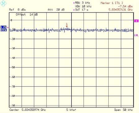
38 Page 37 of 45 Pages Peak power spectral density of digital modulated systems according to (d) Requirements: The peak power spectral density conducted from the intentional radiator to the antenna shall not be greater than 8dBm in any 3kHz band during any time interval of continuous transmission Test Procedure: The measurements were performed in normal (transmitting) mode of operation for carrier (channel) frequency at bottom, middle and the top of the GHz frequency range. The EUT RF output was connected to the Spectrum Analyzer and accounted with cable loss in measurement. The maximum level in a 3kHz bandwidth is measured with: RBW=3kHz; VBW>3kHz, sweep time=span/3khz and video averaging is turned off. The PSD is the highest level found across the emission in any 3kHz band. Additionally, the peak power spectral density from combined (max.) output was calculated and presented in table 11.
39 Page 38 of 45 Pages Test Results: All test results met the requirements. The summaries of Peak Power measurements are shown in Tables Frequency MHz Rate Modulation Mbps mode Output 1 PSD [dbm] Output 2 PSD [dbm] Output 3 PSD [dbm] Limit [dbm] Margin [db] Output 1 Plot number Margin [db] Output 2 Plot number Margin [db] Output 3 Plot number g g g Table 10. PSD (Outputs 1-3) test results. Frequency MHz Rate Mbps Modulation mode Limit [dbm] Calculated Combined (max) Output *, PSD [dbm] Margin [db] g g g Table 11. PSD (Combined Output) test results. (*)- Calculated Combined (max) Output, PSD [dbm] is the sum of the measured PSD from all Output terminals, where each result (PSD from separate output terminal) mathematically conversed from Logarithm to linear units. The results were present in dbm. For example, the calculation for 5835 MHz frequency is the following: 1. (-7.37) dbm = 0.18mW; (-7.54) dbm = 0.18mW; (-7.55) dbm = 0.18mW; =0.54 [mw] mw = dbm


40 Page 39 of 45 Pages Plot # 61. Transmitter output 1. Low frequency. Plot # 62. Transmitter output 2. Low frequency. Plot # 63. Transmitter output 1. Middle frequency. Plot # 64. Transmitter output 2. Middle frequency. Plot # 65. Transmitter output 1. High frequency. Plot # 66. Transmitter output 2. High frequency.


41 Page 40 of 45 Pages Plot # 67. Transmitter output 3. Low frequency. Plot # 68. Transmitter output 3. Middle frequency. Plot # 69. Transmitter output 3. High frequency.
42 Page 41 of 45 Pages 8. Appendix 1: Test equipment used All measurements equipment is on SII calibration schedule with a recalibration interval not exceeding once a year. Instrument Manufacturer Model Serial No. Due calibration date Spectrum Analyzer Rohde&Schwarz FSL - 07/09 Spectrum Analyzer HP 8565E 3835A /09 EMI Analyzer HP E7405A SII /09 Antenna Double Ridge 1-18 GHz Antenna SHF-EHF Horn GHz Biconilog Antenna MHz EMCO 3115 SII /09 Schwarzbeck BBHA 9170 SII /09 Schaffner- Chase CBL-6112D S/N /09 Antenna Mast R&S HCM - N/A Metallic turntable R&S HCT N/A Positioning controller R&S HCC - N/A LISN 9 khz 30 MHz Transient limiter MHz FCC LISN- 50/ SII /09 HP 11947A 31074A /09
43 Page 42 of 45 Pages 9. Appendix 2. Antenna Factor and Cable Loss Cable Loss (10m cable + Mast) Point Frequency (MHz) Cable Loss (db) Point Frequency (MHz) Cable Loss (db)
44 Page 43 of 45 Pages For Bilog Antenna, Model Number: CBL 6112D, S/N: Antenna Factors: For Double Ridged Guide Antenna mfr EMCO model 3115 No. f / MHz AF / db/m f / MHz AF / db/m No. F MHz AF db/m F MHz AF db/m F MHz AF db/m For SHF-EHF Horn Antenna Model Number: BBHA 9170, S/N: m Calibration (Vertical and Horizontal polarizations) Point Frequency (GHz) Antenna Factor (db/m)


45 Page 44 of 45 Pages 10. Appendix 3: Test configuration illustration Photo # 1. Radiated emission test set up. Front side view. Photo # 2. Radiated emission test set up. Rear side view. Photo # 3. Radiated emission test set up. Photo # 4. Radiated emission test. General view


46 Page 45 of 45 Pages Photo # 5. Radiated emission test on Outdoor Radio Unit: spurious & restricted bands. Photo # 6. Transmitter conducted measurements.
Title: Test on 5.8 GHz Band Outdoor WiFi (802.11b/g) Wireless Base Station
 Wireless Base Station") Page 20 of 51 Pages 7.5. Conducted spurious emission 7.5.1. Requirements: Clause 15.247(d). In any 100 khz bandwidth outside the frequency band in which the spread spectrum or digitally modulated intentional
Page 20 of 51 Pages 7.5. Conducted spurious emission 7.5.1. Requirements: Clause 15.247(d). In any 100 khz bandwidth outside the frequency band in which the spread spectrum or digitally modulated intentional
Test Report No
 x Test Report No.8312314587 For Synel Industries Ltd. Equipment Under Test: Proximity Reader From The Standards Institution Of Israel Industry Division Telematics Laboratory EMC Section Certificate No.
ACCORDING TO: FCC part 15 subpart C, and subpart B FOR:
 Electrical Hermon Laboratories Ltd. P.O.Box 23, Binyamina 30500, Israel Tel. +972 4628 8001 Fax. +972 4628 8277 E-mail: mail@hermonlabs.com TEST REPORT ACCORDING TO: FCC part 15 subpart C, 15.247 and subpart
FCC CFR47 PART 15 SUBPART C INDUSTRY CANADA RSS-GEN AND RSS-210 CERTIFICATION TEST REPORT FOR BROADCOM BLUETOOTH MODULE MODEL NUMBER: BCM92046MD
 FCC CFR47 PART 15 SUBPART C INDUSTRY CANADA RSS-GEN AND RSS-210 CERTIFICATION TEST REPORT FOR BROADCOM BLUETOOTH MODULE MODEL NUMBER: BCM92046MD IC #: 4324A-BRCM1029 REPORT NUMBER: 07U11199-1C ISSUE DATE:
Ave output power ANT 1(dBm) Ave output power ANT 2 (dbm)
 Ave output power ANT 2 (dbm)") Page 41 of 103 9.6. Test Result The test was performed with 802.11b Channel Frequency (MHz) power ANT 1(dBm) power ANT 2 (dbm) power ANT 1(mW) power ANT 2 (mw) Limits dbm / W Low 2412 7.20 7.37 5.248 5.458
Page 41 of 103 9.6. Test Result The test was performed with 802.11b Channel Frequency (MHz) power ANT 1(dBm) power ANT 2 (dbm) power ANT 1(mW) power ANT 2 (mw) Limits dbm / W Low 2412 7.20 7.37 5.248 5.458
FCC Test Report. Report No.: PTCDQ FC01
 Page 1 of 63 FCC Test Report Report No.: PTCDQ04170450501-FC01 FCC ID : 2AL2XW801 APPLICATION PURPOSE : Original Equipment PRODUCT DESIGNATION : WIFI DoorBell BRAND NAME : EASTIC MODEL NAME : W801, W802,
SHENZHEN LCS COMPLIANCE TESTING LABORATORY LTD. FCC ID: 2ADPC-G6 Report No.: LCS E
 2) Sequence of testing 30 to 1 GHz Setup: --- The equipment was set up to simulate a typical usage like described in the user manual or described by manufacturer. --- If the EUT is a tabletop system, a
7. Transmitter Radiated Spurious Emissions and Conducted Spurious Emission
 7. Transmitter Radiated Spurious Emissions and Conducted Spurious Emission 7.1 Test Setup Refer to the APPENDIX I. 7.2 Limit According to 15.247(d), in any 100 khz bandwidth outside the frequency band
Pico 900MHz 1W FHSS Module Model: p900 FCC ID: NS913P900. Applicant:
 Pico 900MHz 1W FHSS Module Model: p900 Applicant: Microhard Systems Inc. 150 Country Hills Landing NW Calgary, Alberta Canada T3K 5P3 In Accordance With Federal Communications Commission (FCC) Part 15,
FCC CFR47 PART 15 SUBPART C INDUSTRY CANADA RSS-247 ISSUE 1 BLUETOOTH LOW ENERGY CERTIFICATION TEST REPORT FOR
 FCC CFR47 PART 15 SUBPART C INDUSTRY CANADA RSS-247 ISSUE 1 BLUETOOTH LOW ENERGY CERTIFICATION TEST REPORT FOR WLAN 2X2 MIMO 802.11a/b/g/n/ac with BLUETOOTH MODEL NUMBER: P2180 REPORT NUMBER: 15U21878-E2V1
FCC TEST REPORT FCC ID: PFNDMS2344UHDW
 Table of Contents FCC Measurement Report 1. Introduction 2. Product Information 3. Description of Tests 4. Test Condition 5. Test Results 5.1 Summary of Test Results 5.2 6 db Bandwidth 5.3 Maximum Peak
FCC CFR47 PART 15 SUBPART C CERTIFICATION TEST REPORT FOR PCMCIA RFID READER CARD MODEL NUMBER: MPR6000 FCC ID: NTTWJMPR6XXX REPORT NUMBER: 04U2954-3
 FCC CFR47 PART 15 SUBPART C CERTIFICATION TEST REPORT FOR PCMCIA RFID READER CARD MODEL NUMBER: MPR6000 FCC ID: NTTWJMPR6XXX REPORT NUMBER: 04U2954-3 ISSUE DATE: NOVEMBER 22, 2004 Prepared for WJ COMUNICATIONS
FCC 47 CFR PART 15 SUBPART C INDUSTRY CANADA RSS-210 ISSUE 8 BLUETOOTH LOW ENERGY CERTIFICATION TEST REPORT FOR. 2.4GHz LE MODULE MODEL NUMBER: RN4020
 FCC 47 CFR PART 15 SUBPART C INDUSTRY CANADA RSS-210 ISSUE 8 BLUETOOTH LOW ENERGY CERTIFICATION TEST REPORT FOR 2.4GHz LE MODULE MODEL NUMBER: RN4020 REPORT NUMBER: 14U17191-1 ISSUE DATE: MARCH 21, 2014
Electrical FOR:
 839.01 Electrical Hermon Laboratories Ltd. Harakevet Industrial Zone, Binyamina 30500, Israel Tel. +972-4-6288001 Fax. +972-4-6288277 E-mail: mail@hermonlabs.com TEST REPORT ACCORDING TO: EN 300 113-2
XBee Series 2 OEM RF Module Model No.: XBEE2 FCC ID: OUR-XBEE2. Applicant: MaxStream, Inc. 355 South 520 West Suite 180 Lindon, UT 84042
 XBee Series 2 OEM RF Module Model No.: XBEE2 Applicant: MaxStream, Inc. 355 South 520 West Suite 180 Lindon, UT 84042 In Accordance With Federal Communications Commission (FCC) Part 15, Subpart C, Section
Page 1 of 51 Report No.: T TEST REPORT FCC ID: 2AGJ5WAP-30. In Accordance with: FCC PART 15, SUBPART C : 2015 (Section 15.
 Page 1 of 51 Report No.: T1851663 01 TEST REPORT FCC ID: 2AGJ5WAP-30 Applicant Address : Gonsin Conference Equipment Co., Ltd : No.401-406,Block C, Idea Industry Park, No.41 Fengxiang Road, Shunde, Foshan,
TABLE OF CONTENTS 1. GENERAL INFORMATION... 4
 TABLE OF CONTENTS 1. GENERAL INFORMATION... 4 1.1. EUT DESCRIPTION... 4 1.2. TEST STANDARDS AND RESULTS... 5 1.3. FACILITIES AND ACCREDITATIONS... 6 1.3.1. FACILITIES... 6 1.3.2. TEST ENVIRONMENT CONDITIONS...
Revision history. Revision Date of issue Test report No. Description KES-RF-14T0042 Initial
 Page (2 ) of (34) Revision history Revision Date of issue Test report No. Description - 2014.08.25 Initial Page (3 ) of (34) TABLE OF CONTENTS 1. General information... 4 1.1. EUT description... 4 1.2.
ELECTROMAGNETIC EMISSIONS COMPLIANCE REPORT
 Page: 1 of 57 ELECTROMAGNETIC EMISSIONS COMPLIANCE REPORT INTENTIONAL RADIATOR CERTIFICATION TO FCC PART 15 SUBPART C REQUIREMENT OF Product name: Brand Name: Model Name: FCC ID: REPORT NO: Bluetooth Headset
TEST REPORT. Reference No... : WTS16S E FCC ID... : SJ8-UDR777HD. Applicant... : RDI Technology Shenzhen Co., Ltd.
 TEST REPORT Reference No.... : WTS16S0449305E FCC ID... : SJ8-UDR777HD Applicant... : RDI Technology Shenzhen Co., Ltd. Address... : Building C1, Xintang Industrial Park East Baishixia, Fuyong, Baoan,
Version TEST REPORT NO. DATE DESCRIPTION
 Version NO. DATE DESCRIPTION HCTR1302FR13 February 14, 2013 - First Approval Report - Additional Model Name Page 2 of 25 Table of Contents 1. GENERAL INFORMATION... 4 2. EUT DESCRIPTION... 4 3. TEST METHODOLOGY...
FCC 47 CFR PART 15 SUBPART C CERTIFICATION TEST REPORT FOR. RF ID Reader MODEL NUMBER: A-405 FCC ID: WFQITCS-A-405 IC: 10717A-ITCSA405
 FCC 47 CFR PART 15 SUBPART C CERTIFICATION TEST REPORT FOR RF ID Reader MODEL NUMBER: A-405 REPORT NUMBER: 10906664A ISSUE DATE: December 12, 2015 Prepared for RF Controls LLC 1400 S 3 RD Street Suite
FCC CFR47 PART 15 SUBPART C CERTIFICATION TEST REPORT FOR DUAL RADIO OUTDOOR ACCESS POINT MODEL NUMBER: AP-ONE FCC ID: SWX-AP1R2
 FCC CFR47 PART 15 SUBPART C CERTIFICATION TEST REPORT FOR DUAL RADIO OUTDOOR ACCESS POINT MODEL NUMBER: AP-ONE REPORT NUMBER: 04U3091-1 ISSUE DATE: JANUARY 07, 2005 Prepared for UBIQUITI NETWORKS 1111
FCC ID: B4OCC264BPA-S
 FCC TEST REPORT FCC ID: B4OCC264BPA-S Product : Bluetooth LE Module Model Name : CC264BPA-S, CC265BPA-S, CC26xBPA Brand : GT-tronics Report No. : PTC801181160622E-FC01 Prepared for GT-tronics HK Ltd Unit
ELECTRICAL TESTING ACCORDING TO: FCC 47CFR part 15 subpart C (DTS) and subpart B FOR:
 and subpart B FOR:") ELECTRICAL TESTING 0839.01 Hermon Laboratories Ltd. P.O. Box 23, Binyamina 3055001, Israel Tel. +972 4628 8001 Fax. +972 4628 8277 E-mail: mail@hermonlabs.com TEST REPORT ACCORDING TO: FCC 47CFR part 15
ELECTRICAL TESTING 0839.01 Hermon Laboratories Ltd. P.O. Box 23, Binyamina 3055001, Israel Tel. +972 4628 8001 Fax. +972 4628 8277 E-mail: mail@hermonlabs.com TEST REPORT ACCORDING TO: FCC 47CFR part 15
FCC C2PC Test Report
 FCC C2PC Test Report FCC ID Equipment Model No. Brand Name Applicant : SQGBT800 : BTv4.0 Dual Mode USB Dongle : BT820 : Laird Technologies : Laird Technologies Address : 11160 Thompson Ave. / Lenexa, Kansas
FCC CERTIFICATION TEST REPORT
 Report No:DDT-RE120176 Issued Date: 2013/01/05 FCC CERTIFICATION TEST REPORT FOR Applicant : AliMed Inc. Address : 297 High St Dedham Ma 02026 Equipment under Test : Alert transmitter Model No : #712716
ELECTROMAGNETIC EMISSIONS COMPLIANCE REPORT
 Page: 1 of 54 ELECTROMAGNETIC EMISSIONS COMPLIANCE REPORT INTENTIONAL RADIATOR CERTIFICATION TO FCC PART 15 SUBPART C REQUIREMENT FULL MODULE APPROVE OF Product Name: Brand Name: Model Name: Model Differences:
ELECTRICAL TESTING
 ELECTRICAL TESTING 0839.01 Hermon Laboratories Ltd. Harakevet Industrial Zone, Binyamina 30500, Israel Tel. +972-4-6288001 Fax. +972-4-6288277 E-mail: mail@hermonlabs.com TEST REPORT ACCORDING TO: FCC
FCC Test Report. Wayne Hsu / Assistant Manager
 FCC Test Report Equipment : Wireless Pedometer/Tracker Brand Name : ASE Group Model No. : M903 Standard : 47 CFR FCC Part 15.247 Operating Band : 2400 MHz 2483.5 MHz FCC Classification : DTS Applicant
COMMUNICATION CERTIFICATION LABORATORY 1940 West Alexander Street Salt Lake City, UT
 COMMUNICATION CERTIFICATION LABORATORY 1940 West Alexander Street Salt Lake City, UT 84119 801-972-6146 Test Report Certification TEST OF: LOZ-5S1-W FCC ID: R33LOZ5S11 To FCC PART 15, Subpart C (15.203,
FCC CFR47 PART 15 SUBPART C INDUSTRY CANADA RSS-210 ISSUE 7 CERTIFICATION TEST REPORT FOR g WIRELESS LAN + BLUETOOTH PCI-E MINI CARD
 FCC CFR47 PART 15 SUBPART C INDUSTRY CANADA RSS-210 ISSUE 7 CERTIFICATION TEST REPORT FOR 802.11g WIRELESS LAN + BLUETOOTH PCI-E MINI CARD MODEL NUMBER: BCM94312HMGB REPORT NUMBER: 09U12439-2 ISSUE DATE:
FCC RF TEST REPORT No SHA-001
 Page 1 of 41 FCC RF TEST REPORT No. 180300344SHA-001 Applicant : Stanley Black & Decker, Inc. 400 Executive Blvd S, Southington, CT 06489 USA Manufacturer : Northwest Instrument Inc. 330 Waterloo Valley
FCC 47 CFR PART 15 SUBPART C AND ANSI C63.10:2009 TEST REPORT
 FCC ID :KA2CS5000LA1 Report No.T150120S01-RP1 FCC 47 CFR PART 15 SUBPART C AND ANSI C63.10:2009 TEST REPORT For Pan & Tilt Wi-Fi Day/Night Camera Model : DCS-5000L, DCS-5000LA1 Trade Name : D-Link Issued
CERTIFICATION TEST REPORT
 CERTIFICATION TEST REPORT Report Number. : 16U23813-E3V3 DTS Applicant : Model : FCC ID : IC : EUT Description : Test Standard(s) : APPLE, INC. 1 INFINITE LOOP CUPERTINO, CA 95014, U.S.A A1822 BCGA1822
Measurement of Digital Transmission Systems Operating under Section March 23, 2005
 Measurement of Digital Transmission Systems Operating under Section 15.247 March 23, 2005 Section 15.403(f) Digital Modulation Digital modulation is required for Digital Transmission Systems (DTS). Digital
FCC Radio Test Report. Orpak Systems Ltd.
 DATE: 20 December 2015 I.T.L. (PRODUCT TESTING) LTD. FCC Radio Test Report for Orpak Systems Ltd. Equipment under test: Fuel Pump Nozzle Reader NNR EXTRA LARGE+SWITCH; NNR EXTRA LARGE* *See customer s
RF Emissions Test Report To Determine Compliance With: FCC, Part 15 Rules and Regulations
 RF Emissions Test Report To Determine Compliance With: FCC, Part 15 Rules and Regulations Model numbers: HT130022 Rev. B. December 17, 2002 Manufacturer: HQ, Inc. 210 9th Steet Drive Palmetto, FL 34221
Test Report Version. Test Report No. Date Description. DRTFCC Jan. 13, 2015 Initial issue
 Test Report Version Test Report No. Date Description DRTFCC1501-0004 Jan. 13, 2015 Initial issue TRF-RF-219(00)130701 Page2 / 37 Table of Contents 1. GENERAL INFORMATION... 4 2. EUT DESCRIPTION... 4 2.1
EMC TEST REPORT - Addendum
 PRODUCT SAFETY AND COMPLIANCE EMC LABORATORY EMC TEST REPORT - Addendum Test Report Number 24262-1 WLAN Report Date 2010-12-08 The test results contained herein relate only to the model(s) identified.
Table of Contents 1. GENERAL INFORMATION SYSTEM TEST CONFIGURATION CONDUCTED EMISSIONS TEST RADIATED EMISSION TEST...
 Table of Contents 1. GENERAL INFORMATION... 4 1.1 PRODUCT DESCRIPTION FOR EQUIPMENT UNDER TEST... 4 1.2 RELATED SUBMITTAL(S) / GRANT (S)... 7 1.3 TEST METHODOLOGY... 7 1.4 EQUIPMENT MODIFICATIONS... 7
Test Report Version. Test Report No. Date Description. DRTFCC Sep. 12, 2014 Initial issue
 DEMC1407-02828 FCC ID: 2AAAQH660W Test Report Version Test Report No. Date Description DRTFCC1409-1165 Sep. 12, 2014 Initial issue Page 2 DEMC1407-02828 FCC ID: 2AAAQH660W Table of Contents 1. EUT DESCRIPTION...
FCC 15B Test Report. : BTv4.0 Dual Mode USB Dongle. Address : Thompson Ave. / Lenexa, Kansas / / USA
 FCC 15B Test Report Equipment Model No. Brand Name Applicant : BTv4.0 Dual Mode USB Dongle : BT820 : Laird Technologies : Laird Technologies Address : 11160 Thompson Ave. / Lenexa, Kansas / 66219 / USA
Test Report. Prepared for: Ubiquiti Networks, Inc. Model: RM5. Description: Rocket M5 FCC ID: SWX-R5M. FCC Part Date of Issue: April 24, 2015
 Test Report Prepared for: Ubiquiti Networks, Inc Model: RM5 Description: Rocket M5 FCC ID: SWX-R5M To FCC Part 15.407 Date of Issue: April 24, 2015 On the behalf of the applicant: Attention of: Ubiquiti
FCC 47 CFR PART 15 SUBPART C AND ANSI C63.10:2009 TEST REPORT
 Report No.T140311S01-RP1 FCC 47 CFR PART 15 SUBPART C AND ANSI C63.10:2009 TEST REPORT For Wireless N Day/Night Network Camera Wireless N Network Camera Model : DCS-932L,DCS-932L_B1 Data Applies To : DCS-930L,DCS-930L_B1
Page 1 of 20 No.: HM TEST REPORT FCC PART 15 SUBPART C CERTIFICATION REPORT FOR LOW POWER TRANSMITTER. TEST REPORT No.
 Page 1 of 20 FCC PART 15 SUBPART C CERTIFICATION REPORT FOR LOW POWER TRANSMITTER Equipment Under Test [EUT]: Model Number: Applicant: FCC ID : Radio Controlled Tank FH002 Zhongshan Fu Hai Electronics
APPLICATION FOR CERTIFICATION On Behalf of Futaba Corporation Radio Control Model No.:T10CG-2.4G FCC ID:AZPT10CG-24G Brand : Futaba
 FCC ID. AZPT10CG-24G Page 1 of 56 APPLICATION FOR CERTIFICATION On Behalf of Futaba Corporation Radio Control Model No.:T10CG-2.4G FCC ID:AZPT10CG-24G Brand : Futaba Prepared for : Futaba Corporation 1080
FCC 47 CFR PART 15 SUBPART C AND ANSI C63.10:2013 TEST REPORT
 FCC 47 CFR PART 15 SUBPART C AND ANSI C63.10:2013 TEST REPORT For Smart Home Outdoor Camera Model : SVO-1601-220 ; SVO-1601-110 Trade Name: BOSCH Issued for Robert Bosch Taiwan Co., Ltd. 6F, No. 90,Jian
FCC REPORT. 570 E1 Camino Real #200, Redwood City, CA 94063, United Manufacturer:
 FCC REPORT Applicant: Address of Applicant: Manufacturer: Striiv Inc. 570 E1 Camino Real #200, Redwood City, CA 94063, United States Striiv Inc. Address of 570 E1 Camino Real #200, Redwood City, CA 94063,
TEST REPORT. Table of Contents
 Page:2 of 43 Table of Contents 1. DOCUMENT POLICY AND TEST STATEMENT... 4 1.1 DOCUMENT POLICY... 4 1.2 TEST STATEMENT... 4 2. DESCRIPTION OF EUT AND TEST MODE... 4 2.1 GENERAL DESCRIPTION OF EUT... 4 2.2
ITL Page 2 of 71 Report No.:
 ITL Page 1 of 71 Report No.: 12092752 TEST REPORT Applicant: Address of Applicant: Harman International Industries, Incorporated 8500 Balboa Blvd, Northridge, CA 91329, United States Manufacturer: Address
FCC Test Report. : RV340W Dual WAN Wireless-AC VPN Router. Standard : 47 CFR FCC Part : 2400 MHz MHz
 FCC Test Report Equipment Brand Name Model No. FCC ID : RV340W Dual WAN Wireless-AC VPN Router : CISCO : RV340W : VUI-RV340W Standard : 47 CFR FCC Part 15.247 Frequency Equipment Class Applicant Manufacturer
TEST REPORT : 2AIB7MGS. TEST DATE : to
 TEST REPORT APPLICANT : Hohem Technology Co.,Ltd PRODUCT NAME : 3-Axis Stabilizing Gimbal for Smartphone MODEL NAME BRAND NAME FCC ID STANDARD(S) : isteady Mobile : Hohem : 2AIB7MGS : 47 CFR Part 15 Subpart
TEST REPORT. Issued for: ShenZhen MYGT Co.,LTD D3 Tongfuyu Industrial Area Community of Shajing Town, Baoan, Shenzhen, China.
 TEST REPORT FCC ID: 2AMKEMY-C11 Product: Wireless Gamepad Model No.: MY-C11 Additional Model No.: TKGC01 Trade Mark: N/A Issued Date: Oct. 16, 2017 Issued for: ShenZhen MYGT Co.,LTD D3 Tongfuyu Industrial
F2 Labs Peters Road Middlefield, Ohio United States of America
 1674 Peters Road Middlefield, Ohio 4462 United States of America www.f2labs.com CERTIFICATION TEST REPORT Manufacturer: Applicant: Product Description: Libra Industries, Inc. 777 Division Drive Mentor,
FCC Test Report. Report No.: AGC FE03. MODEL NAME : Ci3, Ti3, CB3, AO, UI, Vinyl I, Vinyl B, M2
 Page 1 of 51 FCC Test Report FCC ID : VO8CI3 APPLICATION PURPOSE : Original Equipment PRODUCT DESIGNATION : Bluetooth headset BRAND NAME : Bluedio MODEL NAME : Ci3, Ti3, CB3, AO, UI, Vinyl I, Vinyl B,
TEST REPORT. Shenzhen, PRC.
 TEST REPORT Reference No.... : WTS16S0449309E FCC ID... : SJ8-UDRC57 Applicant... : RDI Technology Shenzhen Co., Ltd. Address... : Building C1, Xintang Industrial Park East Baishixia, Fuyong, Baoan, Shenzhen,
For. Unit D16/F. should not use it to claim FCC ID: 2AAIN-MNGLOS
 Page 1 of 49 TESTT REPORT For Applicant : ACOUSTMAX INTERNATIONAL CO.., LTD Unit D16/F Cheuk Nang Plaza 250 Hennessy Road Address : WanchaiHongKong Product Name : Monster GLO Model Name : MNGLO-S, MNGLO-L,MNGLO-M,MNGLO-Mini
5. Maximum Conducted Output Power
 Report Number: F690501/RF-RTL009890-2 Page: 70 of 97 5. Maximum Conducted Output Power 5.1. Test setup EUT Attenuator Power sensor Note PC 5.2. Limit FCC 15.407 (a)(1)(iv) For client devices in the 5.15-5.25
FCC 47 CFR PART 15 SUBPART C CERTIFICATION TEST REPORT FOR. Bluetooth Remote Control for Video Set Top Box MODEL NUMBER: IPRC1000 FCC ID: 2ABTE-L3YJC9
 FCC 47 CFR PART 15 SUBPART C CERTIFICATION TEST REPORT FOR Bluetooth Remote Control for Video Set Top Box MODEL NUMBER: IPRC1000 REPORT NUMBER: 15U22448-E1V4 ISSUE DATE: 3/7/2016 Prepared for Verizon Online
FCC Test Report. Report No.: AGC FE04. Attestation of Global Compliance (Shenzhen) Co., Ltd
 Co., Ltd") Page 1 of 74 FCC Test Report Report No.: AGC07248170302FE04 FCC ID : TV7WBM APPLICATION PURPOSE : Original Equipment PRODUCT DESIGNATION : Woobm-USB BRAND NAME : N/A MODEL NAME : Woobm-USB CLIENT : Mikrotikls
Page 1 of 74 FCC Test Report Report No.: AGC07248170302FE04 FCC ID : TV7WBM APPLICATION PURPOSE : Original Equipment PRODUCT DESIGNATION : Woobm-USB BRAND NAME : N/A MODEL NAME : Woobm-USB CLIENT : Mikrotikls
TEST REPORT. For RFID READER/WRITER. In conformity with. FCC CFR 47 Part15 Subpart C
 TEST REPORT For RFID READER/WRITER In conformity with FCC CFR 47 Part15 Subpart C Model: TR3XM-SD01 / TR3XM-SU01 / TR3XM-SN01 FCC ID: MK4TR3XM-SX01 Test Item: RFID READER/WRITER Report No: RY1203Z12R1
FCC 47 CFR PART 15 SUBPART C AND ANSI C63.10:2013 TEST REPORT
 FCC 47 CFR PART 15 SUBPART C AND ANSI C63.10:2013 TEST REPORT For ZigBee Module Model: MD1000 Trade Name: Billion Issued for Billion Electric Co., Ltd. 8F., No.192, Sec. 2, Zhongxing Rd., Xindian Dist.,
A Test Lab Techno Corp. Report Number:1410FR27
 Mode 5: IEEE 802.11n 2.4GHz 40MHz Link Mode 2422 2437 2452 Page 41 of 85 9 Out of Band Conducted Emissions Measurement 9.1. Limit In any 100 khz bandwidth outside the frequency band in which the spread
Test Report. FCC Part 15, Subpart C, Section Industry Canada RSS-210, Issue 7
 Test Report FCC Part 5, Subpart C, Section 5.247 Industry Canada RSS-, Issue 7 Report Number: CWD67-Cert Model: CWD67 Date: March 3, 0 Prepared by: Grace Lin Date: Mar. 3, 0 Grace Lin, Sr. Compliance Engineer
TEST REPORT. Issued for: RUIMA INTERNATIONAL(HK)INDUSTRIAL CO.,LIMITED NO.19 Ruixiang Road, Xinhua Industrial Zone, Huadu District, Guangzhou China
INDUSTRIAL CO.,LIMITED NO.19 Ruixiang Road, Xinhua Industrial Zone, Huadu District, Guangzhou China") TEST REPORT FCC ID: 2AHSJRM-626B Product: Boombox Speaker Model No.: RM-626 Additional Model: STREET HOPPER 6, CANNON 6 Trade Mark: RUIMA Issued Date: Aug. 04, 2016 Issued for: RUIMA INTERNATIONAL(HK)INDUSTRIAL
TEST REPORT FCC ID: 2AHSJRM-626B Product: Boombox Speaker Model No.: RM-626 Additional Model: STREET HOPPER 6, CANNON 6 Trade Mark: RUIMA Issued Date: Aug. 04, 2016 Issued for: RUIMA INTERNATIONAL(HK)INDUSTRIAL
FCC Part 15 Subpart B
 Report No.: 15A111603E-F Page 1 of 23 Test Report FCC Part 15 Subpart B for Electromagnetic Interference of Product: Managed PoE Industrial Ethernet Switch Trade Name: N/A Model Number: IS-DG512P-2F-8;
RF TEST REPORT 2APNR-GW631Q LTE CPE R1805A0254-R3V1
 RF TEST REPORT Applicant FCC ID Product Model Report No. Gosuncn Technology Group Co.,Ltd. 2APNR-GW631Q LTE CPE WF831, WF831+, WF831A, GW631 R185A254-R3V1 Issue Date June 6, 18 TA Technology (Shanghai)
FCC PART & IC RSS GHz FHSS TEST REPORT
 FCC PART 15.247 & IC RSS-247 2.4 GHz FHSS TEST REPORT 849 NW State Road 45 Newberry, FL 32669 USA Ph.: 888.472.2424 or 352.472.5500 Fax: 352.472.2030 Email: info@timcoengr.com Website: www.timcoengr.com
FCC Test Report. : ASE Group 4F,No 133, Sec 4, Mingsheng E Rd, Songshan Dist, Taipei, Taiwan
 FCC Test Report Equipment : Wireless Pedometer/Tracker Brand Name : ASE Group Model No. : M903 Standard : 47 CFR FCC Part 15B Device Class : Class B Applicant Manufacturer : ASE Group 4F,No 133, Sec 4,
FCC 47 CFR PART 15 SUBPART C
 FCC 47 CFR PART 15 SUBPART C Product Type Applicant Address Trade Name Model Number : Wink Relay : Quirky, Inc. : 606 W 28th St, Floor 7 New York NY 10001 United States : Wink : PRLAY-WH01 Test Specification
REVISION HISTORY. The revision history for this document is shown in table. HCT-EM-1801-FC037 January 22, 2018 Initial Release
 REVISION HISTORY The revision history for this document is shown in table. Version Issue Date Description HCT-EM-1801-FC037 January 22, 2018 Initial Release HCT-EM-1801-FC037-R1 January 26, 2018 Revision
TEST REPORT WTN16S E 2AFOYL654UCNN
 TEST REPORT Reference No.... : FCC ID... : Applicant... : Address... : Manufacturer... : Address... : Product Name... : Model No..... : Brand.... WTN16S0754892-1E 2AFOYL654UCNN Le Shi Zhi Xin Electronic
FCC PART TEST REPORT. Zhejiang Flashforge 3D Technology CO., Ltd
 FCC PART 15.247 TEST REPORT For Zhejiang Flashforge 3D Technology CO., Ltd No. 518, Xianyuan Road, Jinhua, Zhejiang, China FCC ID: 2AKLL-ADVENTURER3 Report Type: Original Report Product Type: 3D PRINTER
STC Test Report. Date : Page 1 of 13 No. : HM161169
 Date : 2009-05-11 Page 1 of 13 Applicant (ATS001): Atech Scientific Measurement Limited. Room A-C, 18 Floor, Luk Hop Ind. Bldg, 8 Luk Hop Street, Kowloon Manufacturer: Atech Scientific Measurement Limited.
TEST REPORT # TCB LSR Job #:C-626
 W66 N220 Commerce Court Cedarburg, WI 53012 USA Phone: 262.375.4400 Fax: 262.375.4248 www.lsr.com TEST REPORT # 309135 TCB LSR Job #:C-626 Compliance Testing of: Ingersoll Rand 900MHz Communications Module.
TEST REPORT FCC ID: 2ADMF-HC06. : bluetooth module keyes HC-06, keyes hc-05, FUNDUINO HC-06, FUNDUINO hc-05
 Shenzhen Certification Technology Service Co., Ltd. 2F, Building B, East Area of Nanchang Second Industrial Zone, Gushu 2 nd Road, Bao'an District, Shenzhen 518126, P.R. China TEST REPORT FCC ID: 2ADMF-HC06
FCC & RSS-216 (Class II Permissive Change) Wireless Power Transfer Report. for A Acer Incorporated
 Wireless Power Transfer Report. for A Acer Incorporated") Page 1 of 17 FCC 15.209 & RSS-216 (Class II Permissive Change) Wireless Power Transfer Report for A Acer Incorporated 8F., No.88, Sec. 1, Xintai 5th Rd., Xizhi, New Taipei City 22181, Taiwan (R.O.C) Product
Page 1 of 17 FCC 15.209 & RSS-216 (Class II Permissive Change) Wireless Power Transfer Report for A Acer Incorporated 8F., No.88, Sec. 1, Xintai 5th Rd., Xizhi, New Taipei City 22181, Taiwan (R.O.C) Product
9. MAXIMUM CONDUCTED OUTPUT POWER SPECTRAL DENSITY
 9. MAXIMUM CONDUCTED OUTPUT POWER SPECTRAL DENSITY 9.1. MEASUREMENT PROCEDURE (1). Connect EUT RF output port to the Spectrum Analyzer through an RF attenuator (2). Set the EUT Work on the top, the middle
FCC Test Report (TR )
") FCC Test Report (TR-1012-036-01) Applicant : Starbridge Networks L.L.C. Address : 3265 Meridian Parkway, STE # 134 Weston, FL 33331, USA Manufacturer : Kasda Digital Technology Co., Ltd. Address : B-31
FCC Test Report (TR-1012-036-01) Applicant : Starbridge Networks L.L.C. Address : 3265 Meridian Parkway, STE # 134 Weston, FL 33331, USA Manufacturer : Kasda Digital Technology Co., Ltd. Address : B-31
EMI TEST REPORT FOR CERTIFICATION to FCC PART 15 Subpart C (Section ) & RSS-210
 & RSS-210") Page 1 of 15 EMC Technologies Pty Ltd ABN 82 057 105 549 176 Harrick Road Keilor Park Victoria Australia 3042 Ph: + 613 9365 1000 Fax: + 613 9331 7455 email: melb@emctech.com.au EMI TEST REPORT FOR CERTIFICATION
Page 1 of 15 EMC Technologies Pty Ltd ABN 82 057 105 549 176 Harrick Road Keilor Park Victoria Australia 3042 Ph: + 613 9365 1000 Fax: + 613 9331 7455 email: melb@emctech.com.au EMI TEST REPORT FOR CERTIFICATION
Certificates and reports shall not be reproduced except in full, without the written permission of MET Laboratories, Inc.
 MET Laboratories, Inc. Safety Certification - EMI - Telecom Environmental Simulation 3162 BELICK STREET SANTA CLARA, CALIFORNIA 95054 PHONE (510) 489-6300 FAX (510) 489-6372 June 26, 2009 Ubiquiti Networks
Measurement of RF Interference from a Canopy 900MHz Access Point and Subscriber Module Using A Yagi Antenna
 Measurement of RF Interference from a Canopy 900MHz Access Point and Subscriber Module Using A Yagi Antenna For : Motorola, Inc. 1301 East Algonquin Road Schaumburg, IL 60196 P.O. No. : 40335 Date Tested
REPORT REVISION HISTORY...
 Reference No.: WTS17S0579239E Page 2 of 39 2 Contents Page 1 COVER PAGE... 1 2 CONTENTS... 2 3 REPORT REVISION HISTORY... 3 4 GENERAL INFORMATION... 4 4.1 GENERAL DESCRIPTION OF E.U.T.... 4 4.2 DETAILS
FCC REPORT. Dongguan Hele Electronics Co., Ltd. J11, J12, J13, Q7, Q28, Q26, Q29
 FCC REPORT Applicant: Dongguan Hele Electronics Co., Ltd. Address of Applicant: Dalingya Industrial Zone, Daojiao Town, Dongguan City, Guangdong China Equipment Under Test (EUT) Product Name: Model No.:
FCC CFR47 PART 15 SUBPART C INDUSTRY CANADA RSS-247 ISSUE 1 CERTIFICATION TEST REPORT FOR. WLAN 2X2 MIMO a/b/g/n/ac with BLUETOOTH
 FCC CFR47 PART 15 SUBPART C INDUSTRY CANADA RSS-247 ISSUE 1 CERTIFICATION TEST REPORT FOR WLAN 2X2 MIMO 802.11a/b/g/n/ac with BLUETOOTH MODEL NUMBER: P2180 REPORT NUMBER: 15U21878-E3V2 ISSUE DATE: NOVEMBER
4G FingerVein Station Model No.: 4GFVSTPW FCC ID: QC4-4GFVSTPW. Applicant: Bioscrypt Inc. 505 Cochrane Drive Markham, ON Canada L3R 8E3
 4G FingerVein Station Model No.: 4GFVSTPW Applicant: Bioscrypt Inc. 505 Cochrane Drive Markham, ON Canada L3R 8E3 In Accordance With Federal Communications Commission (FCC) Part 15, Subpart C, Section
FCC REPORT. Dongguan Hele Electronics Co.,Ltd. * In the configuration tested, the EUT complied with the standards specified above.
 Report No.: GTS201708000040F02 FCC REPORT Applicant: Address of Applicant: Manufacturer: Dongguan Hele Electronics Co.,Ltd. Dalingya Industrial Zone,Daojiao Town,Dongguan City,Guangdong,China Dongguan
IC Test Report. SPORTON INTERNATIONAL INC. No. 52, Hwa Ya 1 st Rd., Hwa Ya Technology Park, Kwei-Shan Hsiang, Tao Yuan Hsien, Taiwan, R.O.C.
 IC Test Report APPLICANT : Texas Instruments Incorporated EQUIPMENT : WiFi and Bluetooth Evaluation Board BRAND NAME : Texas Instruments MODEL NAME : WL1835MODCOM8B IC : 451I-WL1835COM STANDARD : ICES-003
FCC ID: 2ALT5-GW6088
 TEST REPORT FCC ID: 2ALT5-GW6088 For GREAT WORLD LTD Electric Heater Model No. : GW-6078TBT, GW-6088TBT, GW-5088C-AMBT, GW-6088TMBT Trade Name : N/A Prepared for : Address : GREAT WORLD LTD 406 Room 1,
FCC Test Report. Report No.: AGC FE02 CLIENT : INNOVATIVE CONCEPTS AND DESIGN LLC. Attestation of Global Compliance (Shenzhen) Co., Ltd.
 Co., Ltd.") Page 1 of 43 FCC Test Report Report No.: AGC03588150607FE02 FCC ID : 2AE6GUHF 6000HHM APPLICATION PURPOSE : ORIGINAL EQUIPMENT PRODUCT DESIGNATION : Wireless Microphone BRAND NAME : Gemini MODEL NAME :
Page 1 of 43 FCC Test Report Report No.: AGC03588150607FE02 FCC ID : 2AE6GUHF 6000HHM APPLICATION PURPOSE : ORIGINAL EQUIPMENT PRODUCT DESIGNATION : Wireless Microphone BRAND NAME : Gemini MODEL NAME :
For. Tzone FCC ID: FCC Part Description: Product TZ-BT04. Report to Tested By: Manager STR I
 FCCC Part 15C Measurement and Test For Report Tzone Digitall Technology Co.., LTD 16D, Haiying Building, South of Caitian Road, Futiann District, Shenzhen China FCC ID: 2AKSQTZBT04 FCC Rule(s): Product
To «Test_Standards» Test of: Radwin Ltd. Outdoor Subscriber Radio Unit. To: FCC CFR 47 Part 15B; ICES-003 Issue 6: 2016
 TEST REPORT ADDENDUM Part 15B & ICES-003 FROM To «Test_Standards» Test of: FCC CFR 47 Part 15B; ICES-003 Issue 6: 2016 Test Report Serial No.: Issue 13 th July 2016 Master Document Number RDWN41 U5 _Master
Report No R-RFUSP28V01. FCC Test Report. Applicant Fluidmesh Networks, LLC Barlcay Blvd.,Buffalo Grove, IL USA
 FCC Test Report Product Name Model No FCC ID. WiFi AP FM1200V-HW R5S-FV Applicant Fluidmesh Networks, LLC. Address 1359 Barlcay Blvd.,Buffalo Grove, IL 60089 USA Date of Receipt Dec. 27, 2012 Issue Date
EMI T E S T R E P O R T
 EMI T E S T R E P O R T - FCC Part 15B - Test Report No. : T38935-00-02TK 27. November 2014 Date of issue Type / Model Name : One Touch Select Plus Flex Product Description : Blood glucose meter with Bluetooth
FCC REPORT. Dongguan Hele Electronics Co.,Ltd. * In the configuration tested, the EUT complied with the standards specified above.
 + Applicant: Address of Applicant: Manufacturer: FCC REPORT Dongguan Hele Electronics Co.,Ltd. Report No.: GTS201708000040F01 Dalingya Industrial Zone,Daojiao Town,Dongguan City,Guangdong,China Dongguan
FCC PART TEST REPORT. Weccan Industrial Limited
 FCC PART 15.249 TEST REPORT For Weccan Industrial Limited Rm209, 2/F, Building W1-A, No.34 Gaoxin South 4th St Hi-Tech Industrial Park, Nanshan District, Shenzhen China FCC ID: Z3CWECCANDRONE Report Type:
Medtronic MiniMed TEST REPORT FOR. GST3 Glucose Sensor Transmitter, MMT-7763A. Tested To The Following Standards:
 Medtronic MiniMed TEST REPORT FOR GST3 Glucose Sensor Transmitter, MMT-7763A Tested To The Following Standards: FCC Part 15 Subpart C Sections 15.247 Date of issue: October 31, 2013 This test report bears
SPORTON FCCC RF APPLICANT EQUIPMENT BRAND NAME MODEL NAME FCC ID STANDARD. : b/g, : EM113-MV : T5U-EM113MV. The product was.
 FCC RF Test Report FCCC RF Test Report APPLICANT EQUIPMENT BRAND NAME MODEL NAME FCC ID STANDARD CLASSIFICATION : Quanta Computer Inc : 802.11b/g, PCI-E Half-sized mini card : QMI : EM113-MV : T5U-EM113MV
FCC Test Report. : Wireless AC750 Range Extender
 FCC Test Report FCC ID Equipment Model No. Brand Name : Applicant Address : I88WRE6505V2 : Wireless AC750 Range Extender : WRE6505 v2 : Zyxel Communications Corporation : No.2 Industry East RD. IX, Hsinchu