PD132 Loop Detector Specification
|
|
|
- Dorthy Phelps
- 5 years ago
- Views:
Transcription

1 PD132 Loop Detector Specification (Version 1.00)
2 Content 1. Application Technical Data Wiring Diagram Use and operational Frequency adjust Sensitivity adjust Filter option Function output relay Duration output time setting Reset Operating Guide Operational Constraints Crosstalk Reinforcing Installation Information Loop and Feeder Specification Sensing Loop Geometry Loop Installation... 7
3 1. Application Loop detectors are used wherever vehicles have to be detected. Like monitoring and safe guarding access ways to counting vehicles. The output signal can be used for controlling door and gate drive mechanisms, operating barriers, controlling traffic light systems in car parks or activating card dispensers in car parks. 2. Technical Data Operating voltage: 220V AC ±10% Power Consumption: 5VA Output relays: 240V/5A AC Frequency range: 20 khz to 170 khz Reaction time: 10ms Signal holding time: Unlimited / limited when loop is permanently covered 10 minutes Sensitivity: adjustable in 8 increments Wiring: 50µH to 1000 µh. Ideal is µH Loop connection wiring: Maximum length 20 meters, twisted at least 20 times per meter Autocorrecting time: 1to 2seconds Operating temperature: -20 C to +65 C Storage temperature: -40 C to +85 C Dimensions (include pedestal ): 78x40x108 mm (L x W x H) Net Weight (include pedestal): 265g Specific set the table below. In trial runs, first sensitivity in the lower stalls, the actual test vehicle detection if no response should be an increased sensitivity to stall, so repeated several times until the car seized stability for normal work. 3 Wiring Diagram Pin Designation 1 Live 230V AC 50/60 Hz 2 Neutral 3 Pulse Relay Normally Open contact 4 Pulse Relay Common contact 5 Presence Normally Open contact 6 Presence Relay Common contact 7 Blue Loop (twist this pair back to the control) 8 Blue Loop 9 Green Earth 10 Presence Relay Normally Closed contact 11 Pulse Relay Normally Closed contact
4 4 Use and operational On powering the PD-132 loop detector, it will automatically calibrate. When correct, it will show 2 LEDs. Do not leave a car on the loop or any other metallic objects when it is calibrating. If the calibration is successful, the detect LED turns off. Failure of the calibration is indicated by a flashing detect LED. When a car passes over the loop, the detect LED turns on. 4.1 Frequency adjust To avoid Crosstalk, please to select different frequencies and screened cables. There are 4 opt frequency.the can be altered by means of DIP1, DIP2Switch. 4.2 Sensitivity adjust The sensitivity can be adjusted on the front of the housing by means of a DIP3, DIP4 and DIP5 dip switches. Specifically set by varying the switches in the table below. Carry out trial runs with different vehicles, cars, bikes etc. Repeat several times until the detector has stability for normal work. Low high
5 4.3 Filter option When the environment has electromagnetic disturbance, resulting in frequent detector mis-operation, turn the DIP6 switch on to increase the filter coefficient, (filtering disturbance.) Please note that when the environment is normal turning DIP6 to the on position may reduce detector sensitivity detection or increase the delay time. Note: If the loop parameters laid are unreasonable, it may also lead to frequent detector mis-operation. These loop parameters should be amended or re-buried loop. 4.4 Function output relay *Pin5, pin 6, pin10: Relay Pulse Output. The output pulse relay can be altered by means of DIP7-Switch OFF when the car enters the loop, the pin5, pin6 closes the contacts and after 500ms switches-off. ON: only when the car leaves the loop, the pin5, pin6 closes the contacts and after 500ms switches-off. *pin3, pin4, pin11: Relay Presence Output. When the loop is occupied by the car or metal, the Pin3, pin 4 closes the contacts until the car leaves the loop. The duration decided by DIP8 4.5 Duration output time setting The duration output time setting can be programmed by means of DIP8-Switch. The presence time may be set to permanent presence or to limited presence. In permanent presence mode the detector will continuously compensate for all environmental changes whilst there is a vehicle present over the loop. The presence mode is set with switch No. 8 and is configured as follows: - SW8 Off - Limited Presence (The loop will automatically recalibrate after 10 minutes) On - Permanent Presence (The loop will only recalibrate by the reset switch) 4.6 Reset By powering off, then on again or pressing the reset panel buttons, or in limited duration mode over time there will detector reset operation. After reset, the detector will be initialized for a car-free state.
6 5. Operating Guide The detector must be installed in a convenient weatherproof location as close to the loop as possible. WARING: 1) This unit must be earthed. 2) Installation and operation by service professional only. 3) Disconnect power before working on this unit. A correct loop configuration and detector installation will ensure a successful inductive loop detection system. 5.1 Operational Constraints Crosstalk When two loop configurations are in close proximity, the magnetic field of one can overlap and disturb the field of the other. This phenomenon, known as crosstalk, can cause false detect and detector lock-up. Crosstalk can be eliminated by: 1. Careful choice of operating frequencies of operation frequency. The closer together the two loops, the further apart the frequencies of operation must be. 2. Separation between adjacent loops.where possible a minimum spacing of 2 meters between adjacent loops. Where possible a minimum spacing of 2 meters between loops should be adhered to. 3. Careful screening of feeder cables if they are routed together with other electrical cables. The screen must be earthed at the detector end only Reinforcing The existence of reinforced steel below the road surface has the effect of reducing the inductance, and therefore the sensitivity, of the loop detection system.in this case two additional turns of wire should be added to the loop. The ideal spacing between the loop cable and steel reinforcing is 150mm, although this is not always practically possible. The slot depth should be kept as shallow as possible, talking care that no part of the loop or feeder remains exposed after the sealing compound has been applied.
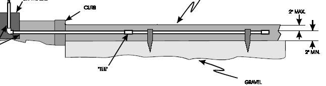
7 6 Installation Information 6.1 Loop and Feeder Specification The loop must consist of insulated wire with a minimum copper cross-sectional area equivalent to 1.5 square millimeters. The feeder should be of the same material but twisted a minimum of 20 twists per meter. Joints in the loop or feeder are not recommended. Where this is not possible, Joints are to be soldered and terminated in a waterproof joint bow. This is extremely important for reliable detector performance. Where long loop feeders are used, or feeders are routed together with other electrical wiring, the use of a screened cable is suggested for the feeder. The screen must be earthed at the detector end only. 6.2 Sensing Loop Geometry Sensing loops should, unless site conditions prohibit, be rectangular in shape and should normally be installed with the longest sides at right angles to the direction of traffic movement. These sides should ideally be 1meter apart. The length of the loop will be determined by the width of the roadway to be monitored. The loop should reach to within 300rnmof each edge of the roadway. In general, loops having a circumference measurement in excess of 10 meters should be installed using 2 turns of wire, while loops of less than 10 meters in circumference should have three or more turns. Loops having a circumference measurement less than 6meters should be have four turns, It is good practice at time of installation to construct adjacent loops with alternate three and four turn windings to escape crosstalk. 6.3 Loop Installation All permanent loop installations should be installed in the roadway by cutting slots with a masonry cutting disc or similar device. A 45 crosscut should be made across the loop corners to reduce the chance of damage that can be caused to the loop cable at right angle corners. Nominal Slot width: 4mm Nominal Slot depth: 30mm to 50mm A slot must also be cut from the loop circumference at one corner of the loop to the roadway edge to accommodate the feeder. A continuous loop and feeder is obtained by leaving a tail long enough to reach the detector before inserting the cable into the loop slot. Once the required numbers of turns of wire are will into the slot around the loop circumference, the wire is routed again via the feeder slot to the roadway edge. A similar length is allowed to reach the detector and these two tree ends are twisted together to ensure they remain in close proximity to one anther.(minimum 20 turns per

8 meter).maximum recommended loop sensitivity decreases as the feeder length increases, so ideally the feeder cable should be kept as short as possible. The loops are seated using a quick-set black epoxy compound or hot bitumen mastic to blend with the roadway surface. 0.5m-1.5m 0.5m-1.5m road edge Sliding road edge Traffic direction Diagram 6
9 Wiring Example to gate controller for pulse exiting It is recommended that the condominium setting is enabled on gate controllers when using inductive loops. Gate Controller Com Start 0 0 Pin Designation 1 Live 230V AC 50/60 Hz 2 Neutral 3 Pulse Relay Normally Open contact 4 Pulse Relay Common contact 5 Presence Normally Open contact 6 Presence Relay Common contact 7 Blue Loop (twist this pair back to the control) 8 Blue Loop 9 Green Earth 10 Presence Relay Normally Closed contact 11 Pulse Relay Normally Closed contact
10 Inductive Loop Detectors Basic Layout Inductive loops work by detecting metal objects such as motor vehicles when the frequency of the loop is disturbed by the passing or presence of a vehicle. There are two basic ways to form a driveway inductive loop. In both cases the nearest wire to the surface 1) A saw cut loop buried directly in the traffic lane and the saw cut filled with a flexible resin. (Typically a concrete or tarmac surface) 2) With a preformed loop made from conduit
11 The loop itself is a continuous run of wire that enters and exits from the same point. A typical size of the loop in a single traffic lane would be 2.5m X 1m and the wire should go three or four times around the loop before exiting at the same point. The two ends of wire that exit the loop and return to the loop control box should be twisted together
12
Short form User Manual
 Nortech Detection Pty Ltd Unit1, Bldg 5, Forest Central Business Park, 49 Frenchs Forest Road, Frenchs Forest NSW 2086 PO Box 6011, Frenchs Forest DC, NSW 2086 Tel: 02 8977 4047 Fax: 02 9475 4742 email:
AGP-0230 USER MANUAL AMANO
 This document is for information only and unless otherwise indicated it is not to form part of any contract. In accordance with the manufacturer s policy of continually updating and improving design, specifications
Single Channel Loop Detector
 Single Channel Loop Detector Model - LD116 The LD116 is a single channel inductive loop card detector designed for parking and access control applications. The detector is connected to an inductive loop
Single Channel Loop Detector
 Single Channel Loop Detector Model - LD106 Series The LD106 is an ultra low power single channel inductive loop detector designed for parking and access control applications. The LD106 can be configured
Single Channel Loop Detector
 Single Channel Loop Detector Model - LD113 Series The LD113 is a single channel inductive loop card detector designed for parking and access control applications. The detector is connected to an inductive
Single Channel Loop Detector
 Single Channel Loop Detector Model - LD160 Series The LD160 is a single channel inductive loop detector designed for traffic control applications. The detector is connected to an inductive loop mounted
FLUX 11 Pocket installation manual SENSITIVE INDUCTIVE LOOP DECTOR
 FLUX 11 Pocket installation manual SENSITIVE INDUCTIVE LOOP DECTOR 1. Introduction The FLUX 11 is a single channel plug-in inductive loop detector designed for vehicle access applications, and interfaces
Single Channel Loop Detector
 Single Channel Loop Detector Model LD120T Series The LD120T is a series of single channel inductive loop detectors. The use of microprocessor and surface mount technology enables a large number of functions
Inductive Sensors Single or Dual Loop Detectors Type LD with teach-in
 Inductive Sensors Single or Dual Loop Detectors Type LD with teach-in Single or Dual loop detector Automatically adjustment of detection level Manual sensitivity for compensations of variations Easy installation
Single Channel Loop Vehicle detector User Manual
 Single Channel Loop Vehicle detector User Manual 1 Introduction CE-L02-J9 is a single channel digital inductive loop vehicle detector. It is used to identify the presence of vehicle by means of an inductive
USER MANUAL ULD 910. October 2003 Revision: 03. Single Channel Vehicle Detector ULD 910. Part Number: MIC
 Single Channel Vehicle Detector ULD 910 USER MANUAL Part Number: MIC0302004 ULD 910 October 2003 Revision: 03 I N D E X PAGE Detector Commissioning... 1 Frequency... 1 Sensitivity... 1 Automatic Sensitivity
SMARTSCAN INFORMATION
 SMARTSCAN INFORMATION SS SLC NOV05 SLC2 and SLC4 SAFETY INDUCTIVE LOOP CONTROLLERS INSTALLATION GUIDE Smartscan Ltd, Pywell Road, CORBY, NN17 5XJ, UK, Tel: +44 (0) 1536 401313, Fax: +44 (0) 1536 268954,
Dual Channel Vehicle Detector ULD 920 USER MANUAL Part Number: MIC ULD 920
 Dual Channel Vehicle Detector ULD 920 USER MANUAL Part Number: MIC0302036 ULD 920 October 2003 Revision: 03 I N D E X PAGE Detector Commissioning... 1 Frequency... 1 Sensitivity... 1 Automatic Sensitivity
Dual Channel Traffic/Parking Detector User Guide
 Dual Channel Traffic/Parking Detector User Guide Installation Manual LD-200 Rev A Dual Channel Vehicle detector LD-200 Page 1 of 4 I Connections LD-200 Dual Channels Traffic Detector User Guide Pin LD-200
BEA s digital inductive single loop solution
 BEA s digital inductive single loop solution Matrix2-S With more standard features than any other loop detector on the market, the Matrix2-S has the flexibility, compatibility and performance to maximize
DSP-20 Dual Channel Vehicle Detector With Directional Logic
 User Manual DSP-20 Dual Channel Vehicle Detector With Directional Logic Diablo Controls, Inc. Copyright 2014 Document: DSP20_MAN_B Released: May 31, 2016 Pros Who Know Trust Diablo 1. Contents 2. Introduction...3
USERS GUIDE MATRIX2 DIGITAL INDUCTIVE LOOP SENSORS
 We open up New Horizons USERS GUIDE MATRIX2 DIGITAL INDUCTIVE LOOP SENSORS APPLICATION The MATRIX is a Digital Inductive Loop Detector used for the detection of vehicular traffic. The MATRIX is the ideal
USERS GUIDE MATRIX P/N SINGLE DIGITAL INDUCTIVE LOOP SENSOR
 USERS GUIDE MATRIX P/N 17500001 SINGLE DIGITAL INDUCTIVE LOOP SENSOR APPLICATIONS The MATRIX Digital Inductive Loop Detector is the ideal solution for parking barrier control, motorized gates and doors,
TECHNICAL MANUAL FOR LOOP DETECTORS WITH POWERFAIL MEMORY Article Codes: RDET1CM & RDET2CM
 TECHNICAL MANUAL FOR LOOP DETECTORS WITH POWERFAIL MEMORY Article Codes: RDET1CM & RDET2CM THIS MANUAL IS INTENDED FOR FOREMEN AND TECHNICAL STAFF IN CHARGE OF THE INSTALLATION, OPERATION AND MAINTENANCE
MD12-2 Metal Loop Detector
 MD12-2 Metal Loop Detector Features Supply 12VDC Adjustable sensitivity (8 levels via dip switch) 2 x Relay outputs (each can be configured individually) Power up and loop activation LED indicator. Industry
DSP-21 Directional Counting Detector
 DSP-21 Directional Counting Detector User Manual Diablo Controls, Inc. Copyright 2015 Document: DSP21_MAN_D Released: February 29, 2016 Pros Who Know Trust Diablo Table of Contents Functional Data... 5
PD230 Enhanced Vehicle Detector USER MANUAL
 Nortech International (Pty) Ltd PO Box 4099 32A Wiganthorpe Road Willowton Hub Pietermaritzburg Pietermaritzburg 3201 South Africa 3200 South Africa Reg. No. 98/1095 Tel: (033) 345 3456 Int. Tel: +27 33
FG2 TWO-CHANNEL DETECTOR
 FG TWO-CHANNEL DETECTOR. DIMENSIS AND ELECTRIC CNECTIS ENGLISH 4 VDC 4 Vdc power supply 3 4 5 6 7 8 9 0 Loop contact Loop contact Loop Loop Dimensions in mm. GENERAL INFORMATI Applications: control of
RME1-RME1BT INSTRUCCIONES DE INSTALACION INSTALLATIEVOORSCHRIFTEN INSTRUCTIONS D INSTALLATION ИНСТРУКЦИИ ПО УСТАНОВКЕ ISTRUZIONI DI INSTALLAZIONE
 8 027908 339119 D811642_01 23-05-08 RILEVATORE DI VEICOLI A SPIRE VEHICLE LOOP DETECTOR DETECTEUR DE VÉHICULES A BOUCLE INDUCTIVE INDUKTIONSSCHLEIFEN-DETEKTOR ZUR DETEKTION VON FAHRZEUgEN DETECTOR DE VEHÍCULOS
SPECIAL SPECIFICATION 1257 Digital Card Rack Non-Invasive Micro Loop Detector Assembly (8 Slot Rack)
") 1993 Specifications CSJ 0924-06-147, etc. SPECIAL SPECIFICATION 1257 Digital Card Rack Non-Invasive Micro Loop Detector Assembly (8 Slot Rack) 1. Description. This Item shall govern for furnishing, and
1993 Specifications CSJ 0924-06-147, etc. SPECIAL SPECIFICATION 1257 Digital Card Rack Non-Invasive Micro Loop Detector Assembly (8 Slot Rack) 1. Description. This Item shall govern for furnishing, and
DSP-10 Vehicle Detector
 User Manual DSP-10 Vehicle Detector Diablo Controls, Inc. Copyright 2014 Document: DSP10_MAN_B Released: August 31, 2015 Pros Who Know Trust Diablo 1. Contents Figures... 3 2. Introduction... 4 3. Technical
FACTORY AUTOMATION. MANUAL LC10-* Laying loops for Loop detector LC10-1 and LC10-2
 FACTORY AUTOMATION MANUAL LC10-* Laying loops for Loop detector LC10-1 and LC10-2 With regard to the supply of products, the current issue of the following document is applicable: The General Terms of
Underground Loops and Loop Detectors. DoorKing Plug-In Loop Detectors and Loop Accessories Single Channel CH1
 S1 S2A B S1S2 A B S1 S2A O SW1 Information Manual Underground Loops and Loop Detectors DoorKing Plug-In Loop Detectors and Loop Accessories 9411 Single Channel with Aux Relay 9410 Single Channel CH1 CH2
Connection and installation manual. Induction loop detector ISD 4, ISD 4/2
 Connection and installation manual Induction loop detector ISD 4, ISD 4/2 warning and safety notes These installation and operating instructions form an integral part of the product. They have been specifically
601/602 Series Inductive Loop Detector
 601/602 Series Inductive Loop Detector Installation Guide Sarasota Series Detectors 1 Copyright 2009 Peek Traffic Corporation Printed in the USA. All rights reserved. Information furnished by Peek is believed
SPECIAL SPECIFICATION 6004 Digital Card Rack Inductive Loop Detector Assembly
 2004 Specifications SPECIAL SPECIFICATION 6004 Digital Card Rack Inductive Loop Detector Assembly 1. Description. Furnish and install a digital card rack inductive loop detector assemblies. 2. Materials.
MODEL T-110 SERIES OPERATION MANUAL
 Reno A & E Telephone: (775) 86-00 4655 Aircenter Circle Facsimile: (775) 86-9191 Reno, Nevada 8950 Internet: www.renoae.com USA e-mail: contact@renoae.com MODEL T-110 SERIES OPERATION MANUAL Single Channel
Loops /29/2018 8:00 AM. Ben Luke
 Loops 101 07/29/2018 8:00 AM Ben Luke Ben Luke Electrical Engineer at Reno A&E Engineering Manager for the last 5 Years BS in Electrical Engineering from University of Nevada, Reno Worked at Reno A&E for
ULT-MVP O P E R A T I N G I N S T R U C T I O N S ULTRALOOP V E HI C L E L O O P DETECTOR Johnston Parkway, Cleveland, Ohio 44128
 ULT-MVP ULTRALOOP O P E R A T I N G I N S T R U C T I O N S V E HI C L E L O O P DETECTOR 4564 Johnston Parkway, Cleveland, Ohio 44128 P. 800 426 9912 F. 216 518 9884 Sales Inquiries: salessupport@emxinc.com
Loop Installation. Manual
 Manual Weiss-Electronic GmbH Niederkircher Straße 16 54294 Trier Germany http://www.weiss-electronic.de 2006 All rights reserved Tel.: +49 (0) 6 51 / 8 10 02 0 2/20 Contents 1 GENERAL DESCRIPTION... 4
Operating Instructions
 UltraDTEK Vehicle Loop Detector Operating Instructions PRODUCT OVERVIEW The UltraDTEK vehicle loop detector is plug-in compatible with Elite OmniControl TM board operators and other Elite A ELD enabled
SOUTH DUBLIN COUNTY COUNCIL Traffic Management Centre Roads (Traffic and Transportation) Department
 Department") SOUTH DUBLIN COUNTY COUNCIL Roads (Traffic and Transportation) Department TECHNICAL SPECIFICATION 2 SDCC-TS-02 INDUCTIVE LOOPS & ABOVE GROUND DETECTION REQUIREMENTS FOR THE DESIGN AND INSTALLATION OF TRAFFIC
SOUTH DUBLIN COUNTY COUNCIL Roads (Traffic and Transportation) Department TECHNICAL SPECIFICATION 2 SDCC-TS-02 INDUCTIVE LOOPS & ABOVE GROUND DETECTION REQUIREMENTS FOR THE DESIGN AND INSTALLATION OF TRAFFIC
LMD622 and LMD624 Series
 LMD622 and LMD624 Series Inductive Loop Monitor THIS MANUAL CONTAINS TECHNICAL INFORMATION FOR THE LMD622, LMD622T, LMD624, LMD624H, and LMD624T SERIES INDUCTIVE LOOP MONITOR. REVISION: MARCH 2012 pn 888-062X-001
ULT-DIN O P E R A T I N G I N S T R U C T I O N S ULTRALOOP V E HI C L E L O O P DETECTOR Johnston Parkway, Cleveland, Ohio 44128
 O P E R A T I N G I N S T R U C T I O N S ULT-DIN ULTRALOOP V E HI C L E L O O P DETECTOR 4564 Johnston Parkway, Cleveland, Ohio 44128 P. 800 426 9912 F. 216 518 9884 Sales Inquiries: salessupport@emxinc.com
MATRIX INDUCTIVE LOOP CONTROL BOX
 EN MATRIX INDUCTIVE LOOP CTROL BOX MATRIX-S2-24: single loop with 2 to 24 V AC/DC power supply MATRIX-D2-24: double loop with 2 to 24 V AC/DC power supply MATRIX-S220: single loop with 220 to 240 V AC
ITS specification Inductive loops and feeder cables (ITS-03-01)
") ITS specification Inductive loops and feeder cables (ITS-03-01) NZ Transport Agency Effective from September 2011 Copyright information This publication is copyright NZ Transport Agency (NZTA). Material
ITS specification Inductive loops and feeder cables (ITS-03-01) NZ Transport Agency Effective from September 2011 Copyright information This publication is copyright NZ Transport Agency (NZTA). Material
SECTION 5 TRANSFORMERS
 SECTION 5 TRANSFORMERS Necessary transformers will be installed and maintained by The City of Aspen. The City of Aspen will not furnish transformers unless they are of standard size and voltage as established
Loop Installation. Manual.
 Loop Installation Manual www.rogertechnology.com Contents 1 General 2 Operating mode 3 Safety notes 4 Induction loop 4.1 Loop size and number of turns 4.2 Inductivity of the loop 5 Loop installation 5.1
Inductive Loop Detector
 Naztec Operations Manual For Inductive Loop Detector Model 722TXC TS1/TS2 April 2003 Published by: Naztec, Inc. 820 Park Two Drive Sugar Land, Texas 77478 Phone: (281) 240-7233 Fax: (281) 240-7238 Copyright
Operating Instructions
 ULT-PLG ULTRALOOP Vehicle Loop Detector Operating Instructions CAUTIONS AND WARNINGS CE REQUIREMENT: Use EMX Pre-formed loops with built-in surge suppression for CE compliance. Connect shield on lead in
MODEL L-1200 SERIES OPERATION MANUAL
 Reno A & E Telephone: (775) 826-2020 4655 Aircenter Circle Facsimile: (775) 826-99 Reno, Nevada 89502 Internet: www.renoae.com USA e-mail: contact@renoae.com MODEL L-200 SERIES OPERATION MANUAL Built-in
Driveway Alarm INSTALLATION MANUAL
 WIRELESS ACCESS CONTROLS Driveway Alarm INSTALLATION MANUAL Mounting post Transmitter Receiver Transformer Sensor Kit Includes: Transmitter Module Sensor Receiver Transformer Mounting post (3 pieces) Installation
With Audible Detect Signal
 T-100 SERIES SINGLE CHANNEL SHELF MOUNT DETECTOR Meets and exceeds NEMA TS 1 specification. Six front panel DIP switches provide: Seven levels of sensitivity plus off. Presence or Pulse mode. Four loop
Operating Instructions MAGSTOP Traffic Barrier MIB 20/30/40 MLC Controller Unit
 Operating Instructions MAGSTOP Traffic Barrier MIB 20/30/40 MLC Controller Unit Version 2003_05-1 - TABLE OF CONTENTS 1.0 SAFETY...5 1.1 SAFETY SYMBOLS USED IN THIS HANDBOOK... 5 1.2 GENERAL SAFETY INFORMATION...
Diamond Knowledge Base. Inductive Loop Guide. Introduction
 Diamond Knowledge Base Inductive Loop Guide Introduction An inductive loop is basically a metal detector installed in the surface of the roadway. It consists of electrical wire embedded in the roadway,
Operations Manual. Model NT11 & NT11-E. June 18 th 2002
 Operations Manual Model NT11 & NT11-E June 18 th 2002 3609 North 44 th Street Phoenix, AZ 85018-6023 Internet: www.northstarcontrols.com Fax: (941) 426-0807 Tel: (941) 426-6396 Manual Contents Glossary
INSTRUCTIONS: 1. Record the transmittal letter number, date, and subject on the transmittal record sheet located in the front of the manual.
 MINNESOTA DEPARTMENT OF TRANSPORTATION DEVELOPED BY: Design Standards ISSUED BY: Office of Technical Support Design Services Section TRANSMITTAL LETTER NO. (0-03) MANUAL: Standard Plates DATED: September
WPT-1000 Wireless Probe Transmitter. Owner s Manual
 WPT-1000 Wireless Probe Transmitter Owner s Manual Compliance Complies with AS/NZS 4268 of 2003 Installation: The WPT-1000 transmitter is used with the Farm Alarm WR-1000 receiver. The WPT-1000 transmitter
SUBJECT: Standard Plate 9102 Turf Establishment Areas At Pipe Culvert Ends
 MINNESOTA DEPARTMENT OF TRANSPORTATION DEVELOPED BY: Design Standards ISSUED BY: Office of Project Management and Technical Support, Design Support Section TRANSMITTAL LETTER NO. (17-03) MANUAL: Standard
IRIS \ IRIS-I QUICK SET-UP GUIDE STEP 1 INSTALL
 IRIS \ IRIS-I QUICK SET-UP GUIDE STEP 1 INSTALL Confirm contents of package: 1 sensor, 1 cable, 1 wide lens (default), 1 narrow lens, mounting template, User s Guide. Install the sensor at the desired
SUBJECT: Standard Plate Turf Establishment Areas (at Pipe Culvert Ends)
") MINNESOTA DEPARTMENT OF TRANSPORTATION DEVELOPED BY: Design Standards ISSUED BY: Office of Program Management and Technical Support, Design Support Section TRANSMITTAL LETTER NO. (14-01) MANUAL: Standard
MINNESOTA DEPARTMENT OF TRANSPORTATION DEVELOPED BY: Design Standards ISSUED BY: Office of Program Management and Technical Support, Design Support Section TRANSMITTAL LETTER NO. (14-01) MANUAL: Standard
Manhole or Catch Basin Type A & B Cone Sections Precast - Design F Manhole or Catch Basin Cover (Reducer Cone Section Precast) Design D
 Design D") MINNESOTA DEPARTMENT OF TRANSPORTATION DEVELOPED BY: Design Standards ISSUED BY: Office of Program Management and Technical Support, Design Support Section TRANSMITTAL LETTER NO. (14-02) MANUAL: Standard
MINNESOTA DEPARTMENT OF TRANSPORTATION DEVELOPED BY: Design Standards ISSUED BY: Office of Program Management and Technical Support, Design Support Section TRANSMITTAL LETTER NO. (14-02) MANUAL: Standard
Standard Plate 7036 is discontinued. It is replaced by Standard Plan Pedestrian Curb Ramp Details.
 DEVELOPED BY: Design Standards ISSUED BY: Office of Program Management & Technical Support, Design Support Section TRANSMITTAL LETTER NO. (12-02) MANUAL: Standard Plates DATED: May 11, 2012 SUBJECT: Standard
MODEL C-1000 SERIES OPERATION MANUAL
 Reno A & E Telephone: (775) 826-2020 4655 Aircenter Circle Facsimile: (775) 826-99 Reno, Nevada 89502 Internet: www.renoae.com USA e-mail: contact@renoae.com MODEL C-000 SERIES OPERATION MANUAL Built-in
Double Channel Loop Detector
 Double Channel Loop Detector NBLD-00 series The NBLD00 is a double channel inductive loop detector, designed for parking and vehicle access control. The function of the detector is to detect vehicle presence
4-Channel-Loop-Detector Euro-card plug-in 19"
 IG745/3 IG745/3 S Application range Traffic technology Signal output for traffic light installations Traffic counting Bus classification / car-lorry classification Special options - Detection of traffic
Single Channel Loop Detector
 Single Channel Detector NLD-0 series The NLD0 is a single channel inductive loop detector, designed for parking and vehicle access control. The function of the detector is to detect vehicle presence by
Wisconsin Contractors Institute Continuing Education
 IMPORTANT NOTE: You should have received an email from us with a link and password to take your final exam online. Please check your email for this link. Be sure to check your spam folder as well. If you
RECOGNITION OF VEHICLES BY THE INDUCTION LOOP DETECTOR
 RECOGNITION OF VEHICLES BY THE INDUCTION LOOP DETECTOR FEIG ELECTRONIC GmbH llange Straße 4 l35781 Weilburg / Germany Contents 1. Introduction 2. System Loop Induction Loop Detector 3. What should be known
2. Remove from the Standard Plate manual: Standard Plate Index, Sheets 1-4 of 4, Numerical Index of Standard Plates (August 31, 2012)
") MINNESOTA DEPARTMENT OF TRANSPORTATION DEVELOPED BY: Design Standards ISSUED BY: Office of Program Management & Technical Support, Design Support Section TRANSMITTAL LETTER NO. (12-04) MANUAL: Standard
MINNESOTA DEPARTMENT OF TRANSPORTATION DEVELOPED BY: Design Standards ISSUED BY: Office of Program Management & Technical Support, Design Support Section TRANSMITTAL LETTER NO. (12-04) MANUAL: Standard
For the electronic measurement of current: DC, AC, pulsed..., with galvanic separation between the primary and the secondary circuit.
 Current Transducer IN 1000-S N = 1000 A For the electronic measurement of current: DC, AC, pulsed..., with galvanic separation between the primary and the secondary circuit. Features Closed loop (compensated)
TELESCOPIC GATE MANUFACTURING AND INSTALLATION MANUAL.
 TELESCOPIC GATE MANUFACTURING AND INSTALLATION MANUAL. Telescopic gates have been manufactured for many years essentially in the same way they are largely today. In recent years hardware suppliers have
Telemetrie-Messtechnik Schnorrenberg
 Telemetrie-Messtechnik Schnorrenberg MTP-IND-PWR User Manual Inductive power supply set Power supply for power head 25 and 50mm mounting tape to fix coil on shaft Ferrite tape 30mmx3m CUL 1.00 mm (Enamelled
Current Standard Plates including Transmittal Letters are available on the web at:
 MINNESOTA DEPARTMENT OF TRANSPORTATION DEVELOPED BY: Design Standards ISSUED BY: Office of Project Management and Technical Support, Design Support Section TRANSMITTAL LETTER NO. (17-04) MANUAL: Standard
SHADOWBOX INSTALLATION FOR: Standard 6 H x 8 W Shadowbox Fence 5 x 5 Routed Posts Dog Ear or Straight-Edge Pickets 1.75 x 3.5 Rail
 SHADOWBOX INSTALLATION FOR: Standard 6 H x 8 W Shadowbox Fence 5 x 5 Routed Posts Dog Ear or Straight-Edge Pickets 1.75 x 3.5 Rail Storage and Handling Fence Preparation and Layout Locate and Set Posts
Train Detection Handbook
 Page 1 of 14 Issue and revision record Section/ Issue Date Comments document 1 August 1994 New Document 2 June 1996 Renamed, formerly Track Circuit See CONTENTS for details of other documents. Train Detection
Installation requirements
 Installation requirements for SUNNY CENTRAL 500U 1 Contents This document describes the requirements which have to be observed for the installation site of the Sunny Central 500U. The installation and
INDEX. Accessories and Components System Unit and Joystick Assembly and Charging the Battery Using with LED System...
 USER GUIDE INDEX Accessories and Components... 4 System Unit and Joystick... 6 Assembly and Charging the Battery... 9 Using with LED System... 11 What is Ground Setting and How It Is Done... 14 Ground
Twisted Wire in the Loop Itself Test
 BD Loops 8161 Monroe Ave Stanton, CA 90680 P: 714-723-0946 F: 714-890-1603 BD Loops Twisted Wire in the Loop Itself Test.......... Observations of a loop s detection performance while the loop wire itself
Current Probes. User Manual
 Current Probes User Manual ETS-Lindgren Inc. reserves the right to make changes to any product described herein in order to improve function, design, or for any other reason. Nothing contained herein shall
Current transducer FHS 40-P/SP600
 Current transducer I PM = 0-100 A Minisens transducer The Minisens transducer is an ultra flat SMD open loop integrated circuit current transducer based on the Hall effect principle. It is suitable for
Application Note # 5438
 Application Note # 5438 Electrical Noise in Motion Control Circuits 1. Origins of Electrical Noise Electrical noise appears in an electrical circuit through one of four routes: a. Impedance (Ground Loop)
eguard EG2233, EG3333, EG3355, EG3388 & EG8406: Installation and Set-up Procedures Tx 2200 and Rx 4200 Boards
 eguard EG2233, EG3333, EG3355, EG3388 & EG8406: Installation and Set-up Procedures Tx 2200 and Rx 4200 Boards A. Primary Technical Data: Transmitter Operating voltage DC 24V Operating current. < 450mA
For the electronic measurement of current: DC, AC, pulsed..., with galvanic separation between the primary and the secondary circuit.
 Current Transducer IN 1000-S I P N = 1000 A For the electronic measurement of current: DC, AC, pulsed..., with galvanic separation between the primary and the secondary circuit. Features Closed loop (compensated)
Installation Manual. UL 325 Compliant. For Pre-2016 Convenience Open Operators ONLY
 CFORMS TO ANSI/UL- CERTIFIED TO CAN/CSA C.. CLASS MODEL SERIAL HP CFORMS TO ANSI/UL- CERTIFIED TO CAN/CSA C.. CLASS MODEL SERIAL HP CLASS MODEL SERIAL HP Installation Manual Use this manual for circuit
Kentaur Turnstiles Full-height gates
 Kentaur Turnstiles Full-height gates Secure Kentaur Turnstiles Versatile Durable Modular The robust Kentaur turnstiles and full-height gates are especially suitable for securing the perimeter of buildings
Four Channel Inductive Loop Detector
 Naztec Operations Manual For Four Channel Inductive Loop Detector Model 724/224 April 2003 Published by: Naztec, Inc. 820 Park Two Drive Sugar Land, Texas 77478 Phone: (281) 240-7233 Fax: (281) 240-7238
Installation Guide. Capped Cellular PVC Fencing. Table of Contents. Storage and Handling Tools Needed Fence Layout and Locating Posts
 Capped Cellular PVC Fencing Installation Guide Table of Contents Storage and Handling Tools Needed Fence Layout and Locating Posts Installation instructions 4 x 4 Over Sleeve Post - 3.5 Rail Privacy Shadowbox
Kentaur Turnstiles Kentaur Full-Height Gates
 Kentaur Turnstiles Kentaur Full-Height Gates Expertise in perimeter protection «We attach great importance to perimeter protection on our premises. An intelligent fence system and automatic full-height
SDCS-03 DISTRIBUTION NETWORK GROUNDING CONSTRUCTION STANDARD (PART-I) UNDERGROUND NETWORK GROUNDING. Rev. 01
 UNDERGROUND NETWORK GROUNDING. Rev. 01") SDCS-03 DISTRIBUTION NETWORK GROUNDING CONSTRUCTION STANDARD (PART-I) UNDERGROUND NETWORK GROUNDING Rev. 01 This specification is property of SEC and subject to change or modification without any notice
SDCS-03 DISTRIBUTION NETWORK GROUNDING CONSTRUCTION STANDARD (PART-I) UNDERGROUND NETWORK GROUNDING Rev. 01 This specification is property of SEC and subject to change or modification without any notice
Golden Mask Deep Hunter LE
 Golden Mask Deep Hunter LE Golden mask Deep Hunter LE is a pulse induction detector, designed for easy detection of deeply buried large metal objects (larger than 8 cm or 3 ) with LED indication for the
SUBJECT: Standard Plates 4132, 4155, Drainage Structures and Castings Info
 MINNESOTA DEPARTMENT OF TRANSPORTATION DEVELOPED BY: Design Standards ISSUED BY: Office of Project Management and Technical Support, Design Support Section TRANSMITTAL LETTER NO. (18-01) MANUAL: Standard
Com-Trol ADV-6000 Trouble Shooting Guide Click on red text to go to that page in guide
 Com-Trol ADV-6000 Trouble Shooting Guide Click on red text to go to that page in guide Topic Introduction 1 Tool Requirements 1 Trouble Shooting Check List 1 Page(s) Lost communications to controller(s)
PRIVACY INSTALLATION FOR: Standard 6 H x 8 W Privacy Fence 4 x 4 Post Sleeve & Brackets Dog Ear or Straight-Edge Pickets 1.75 x 3.
 PRIVACY INSTALLATION FOR: Standard 6 H x 8 W Privacy Fence 4 x 4 Post Sleeve & Brackets Dog Ear or Straight-Edge Pickets 1.75 x 3.5 Rail Storage and Handling Fence Preparation and Layout Locate and Set
USER MANUAL APG DYNAMIC PROCESSORS MATRIX ARRAY SYSTEMS 4000SP 6000SP 9000SP
 USER MANUAL APG DYNAMIC PROCESSORS MATRIX ARRAY SYSTEMS 4000SP 6000SP 9000SP SAFETY INSTRUCTIONS This symbol, wherever it appears, alerts you to the presence of uninsulated dangerous voltage inside the
Status Date Prepared Reviewed Endorsed Approved
 Discipline Engineering Standard NSW Category Signalling Title Reference Number SDS 17 (RIC Standard: SC 00 13 01 17 SP) Document Control Status Date Prepared Reviewed Endorsed Approved Mar 05 Standards
Dakota Alert. WPT-3000 Wireless Probe Transmitter. Owner s Manual
 Dakota Alert WPT-3000 Wireless Probe Transmitter Owner s Manual Warnings This device complies with Part 15 of the FCC rules, operation of this device is subject to the following conditions: 1. This device
Aqua-Gen 3BR INSTRUCTIONS
 Aqua-Gen 3BR INSTRUCTIONS INSTALLATION INSTRUCTIONS CONTROLLER: Find a suitable location to mount the control box* radio note. The controller must be installed out of direct weather and no closer than
SDCS-03 DISTRIBUTION NETWORK GROUNDING CONSTRUCTION STANDARD (PART-II) OVERHEAD NETWORK GROUNDING. Rev. 01
 OVERHEAD NETWORK GROUNDING. Rev. 01") SEC DISTRIBUTION GROUNDING STANDARD SDCS-03 Part-II Rev.01 SDCS-03 DISTRIBUTION NETWORK GROUNDING CONSTRUCTION STANDARD (PART-II) OVERHEAD NETWORK GROUNDING Rev. 01 This specification is property of SEC
SEC DISTRIBUTION GROUNDING STANDARD SDCS-03 Part-II Rev.01 SDCS-03 DISTRIBUTION NETWORK GROUNDING CONSTRUCTION STANDARD (PART-II) OVERHEAD NETWORK GROUNDING Rev. 01 This specification is property of SEC
Safety Warnings Features Specifications Instrument Layout Operation Preparation AC Current Measurement How to Use Peak Hold Function How to Use The
 Safety Warnings Features Specifications Instrument Layout Operation Preparation AC Current Measurement How to Use Peak Hold Function How to Use The Frequency Selector Switch How to Use Data Hold Function
Heritage MedCall. Sentry E-Call Model HM-527 Resident Host Panel
 Heritage MedCall Sentry E-Call Model HM-527 Resident Host Panel 430-527B 0305 Heritage MedCall, Inc. Issue 1, March 2005 Heritage Medcall Sentry Emergency Call System Model 527 Host Panel Installation
PART 4 STANDARD DRAWINGS FOR CONSTRUCTION
 4.0. INTRODUCTION PART 4 STANDARD DRAWINGS FOR CONSTRUCTION In this document, Ivins City adopts the most recent edition (currently 2007), including all amendments, of the APWA Utah Chapter s Manual of
USER S MANUAL PULSE INPUTS MODULE WITH PROVER SUPPORT
 USER S MANUAL PULSE INPUTS MODULE WITH PROVER SUPPORT D F 7 7 M E www.smar.com Specifications and information are subject to change without notice. Up-to-date address information is available on our website.
For ultra-high precision measurement of current: DC, AC, pulsed..., with galvanic separation between primary and secondary. Applications.
 Current Transducer IT 700-SB ULTRASTAB I PM = 700 A For ultra-high precision measurement of current: DC, AC, pulsed..., with galvanic separation between primary and secondary. Features ± 10 V voltage output
USER MANUAL 600A AC Clamp Meter + NCV Model MA610
 USER MANUAL 600A AC Clamp Meter + NCV Model MA610 Additional User Manual Translations available at www.extech.com Introduction Thank you for selecting the Extech MA610 Clamp Meter. This meter measures