OMNIPOWER direct and CT meters. Technical Description
|
|
|
- Angela Carol Simpson
- 5 years ago
- Views:
Transcription


1 Technical Description
2 Contents 1 Disclaimer Copyright information Third parties Introduction to OMNIPOWER Technical specification Electrical specifications Technical Data for OMNIPOWER direct meters Technical Data for OMNIPOWER CT meters Mechanical specifications Type number overview Approvals Connection diagrams Terminal numbering How to use OMNIPOWER meters Installation and power-up Power-up/Start-up sequence Display functions Push-button functionalities Tamper Meter status logger ( ) Time management Backup Hour counters Calendar and daylight saving time plan RTC setting and adjustment using pushbutton RTC adjustment logger ( ) Power and energy measurements Power measurements Energy registration Calculation methods of an OMNIPOWER three-phase meter Mean power values Kamstrup A/S Technical Description _D1_GB_
3 4.4.5 Peak power values Energy tariff registers Data loggers Load profile ( ) Monthly debiting logger ( ) Daily/weekly/monthly debiting logger ( ) Analysis logger ( ) Meter readout Manual display readout digit value field Protocols Local readout via optical interface METERTOOL OMNIPOWER Integrated OMNICON radio mesh connectivity Integrated OMNICON point-to-point connectivity Full encryption on all interfaces M-Bus and RS-485 connectivity Modularity options Primary modules CCC modules Disconnect functionality ( ) Disconnect function in the meter Manual disconnection and reconnection Remote disconnection from a smart metering system Smart disconnect Disconnection basis Current-controlled disconnection Power-controlled disconnection Delayed disconnection Reconnection Overvoltage disconnection Disconnection on meters with APS Kamstrup A/S Technical Description _D1_GB_
4 Event logger for disconnect/connect history ( ) Prepayment Prepayment principle Power quality measurements Frequency measurements Voltage variations Voltage outage Configuration of power voltage measurements Rapid voltage change Supply voltage unbalance Total harmonic distortion (THD) Readout of the power quality measurements Power factor Neutral fault detection Other smart grid functionalities Firmware upload Alarm handling/push alarms All phase power outage alarm Control of external load relays Multi-utility options Miscellaneous use Pulse inputs in the module area Examples of pulse input from an electricity meter Pulse outputs in module area S0 output Auxiliary power supply (APS) Ordering specification Meter configuration Hardware configuration Software configuration Display configuration Tariff control configuration Kamstrup A/S Technical Description _D1_GB_
5 5.6 Load control configuration Smart disconnect setup Sealable push-button configuration protocol configuration Packing Box solution Pallet solution Customer labels Sealing Accessories Kamstrup A/S Technical Description _D1_GB_
6 Revisions history: Document revision Description Meter software revision A1 A2 First release of the technical description for OMNIPOWER direct meters. Does not include OMNIPOWER CT. Update of the section with power quality measurements. OMNIPOWER direct meters: - SW no: , rev. B1 > P1 OMNIPOWER direct meters: - SW no: , rev. B1 > P1 A3 Includes OMNIPOWER ST variant. (Symmetric terminals) OMNIPOWER direct meter: - SW no: , rev. P1 > P1 B1 Includes OMNIPOWER CT OMNIPOWER direct meters: - SW no: , rev. Q1 OMNIPOWER CT meter: - SW no: , rev. Q1 C1 Includes new overvoltage disconnect functionality. OMNIPOWER direct meters: - SW no: , rev. R1, S1, T1, U1 OMNIPOWER CT meter: - SW no: , rev. R1, S1, T1, U1 D1 Includes new OMNIPOWER variant with Last gasp and encryption. OMNIPOWER direct meters: - SW no: , rev. R1, S1, T1, U1 - SW no rev. D1, E1 (No DLMS) - SW no rev. D1 (No DLMS) OMNIPOWER CT meter: - SW no: , rev. R1, S1, T1, U1 6 Kamstrup A/S Technical Description _D1_GB_
7 1 Disclaimer Although the information and recommendations in this document are presented in good faith and believed to be correct, Kamstrup makes no representations or warranties as to the completeness or accuracy of the information. Information is supplied upon the condition that the persons receiving same will make their own determination as to its suitability for their purposes prior to use. In no event will Kamstrup be responsible for damages of any nature whatsoever resulting from the use of or reliance upon information from this site or the products to which the information refers. Kamstrup does not warrant the accuracy or timeliness of the information in this document and has no liability for any errors or omissions in the document. This document is provided on an as is basis. No representations or warranties, either express or implied, of merchantability, fitness for a particular purpose or of any other nature are made hereunder with respect to information or the products to which information refers. 1.1 Copyright information Copyright Kamstrup A/S Industrivej 28 Stilling DK-8660 Skanderborg, Denmark All Rights Reserved The graphics and content in this document are the copyrighted work of Kamstrup and contain proprietary trademarks and trade names of the Company. Kamstrup hereby authorizes copying of documents for noncommercial use or for educational research only. The above copyright notice must appear on every such copy. No right or license is granted under any copyright, patent or trademark of Kamstrup to any other party. 1.2 Third parties This document may contain links to other parties. Kamstrup makes no warranty or representation regarding any linked information appearing therein. Such links do not constitute an endorsement by Kamstrup of any such information and are provided only as a convenience. Kamstrup is not responsible for the content or links displayed by third parties. Kamstrup A/S Technical Description _D1_GB_


8 2 Introduction to OMNIPOWER Kamstrup OMNIPOWER meters are prepared for the future demands, required by smart grid implementations. It provides a detailed insight into consumption patterns at the low-voltage part of the power grid and is also a grid sensor for collection of relevant power quality information. OMNIPOWER offers a list of features e.g.: Optimized functionalities for smart metering systems Communication for smart home applications Security against tampering Ultra-low power consumption Remote firmware update; approved according to WELMEC 7.2. From the factory, the meter can be configured to measure both imported and exported energy. Measurements are saved in a permanent memory. As default, the OMNIPOWER meter can generate load profiles in all four quadrants. A load profile provides detailed information about consumed and produced energy. An additional logger with 16 channels contains data for analysis purposes. Part of OMNIA Suite OMNIPOWER with integrated OMNICON radio communication is an essential part of Kamstrup s OMNIA Suite allcomprising smart grid platform, shown in the figure, which offers a full line of smart technology, support and knowledge. OMNIPOWER Smart Meters for electricity Figure 1: OMNIA Suite overview. As part of OMNIA Suite, OMNIPOWER can be used as the gateway for collecting other consumption types such as water, gas, heating and cooling. It is also prepared for Home Area Network (HAN) communication via a Consumer Communication Channel (CCC) module which can be inserted by the consumer on the meter front. 8 Kamstrup A/S Technical Description _D1_GB_
9 3 Technical specification OMNIPOWER provides a long range of technical and mechanical features with high performance and reliability. The following technical specifications are both valid for OMNIPOWER direct and CT meters. 3.1 Electrical specifications OMNIPOWER meters are constructed with independent and galvanically separated measuring systems (the number of measuring systems depends on the meter type). This ensures a correct measurement irrespective of how many and which measurement systems are used. A switch mode supply feeds measuring circuits and the main processor with voltage. Furthermore, the switch mode supply in combination with varistors and power resistors functions as an excellent transient protection. The use of shunt and switch mode supply also makes sure that OMNIPOWER direct meters are immune to magnetic influence. Measured and calculated data is safely stored in an integrated non-volatile memory (EEPROM). Technical data: Nominal frequency, f n 50 or 60 Hz ± 5 % Phase displacement Unlimited Data storage Display EEPROM; > 10 years without voltage LCD, 7 mm digit height (value field) LCD, 5 mm digit height (identification readings) LCD, 3 mm digit height (voltage readings) Real-time clock (RTC) Accuracy Typically 5 ppm at 23 C Backup battery lifetime Supercap lifetime Supercap backup time > 10 years at normal operation > 10 years at normal operation 7 days at fully charged Kamstrup A/S Technical Description _D1_GB_
10 3.1.1 Technical Data for OMNIPOWER direct meters Measuring principle: Current: Voltage: One-phase current measurement via current shunt One-phase voltage measurement via voltage divider Nominal voltage, Un 3x230 VAC -20 % % (for Aron meter only) 1x230 VAC -20 % % 2x230/400 VAC -20 % % 3x230/400 VAC -20 % % Current, Itr - Ib (Imax) OMNIPOWER three-phase and single-phase meter Without breaker (60)A (80)A (100)A With breaker (60)A (80)A (100)A Accuracy class, Active energy MID: Class A, Class B IEC: Class 2, Class 1 Reactive energy IEC: Class 3, Class 2 Own consumption (per phase) 1 OMNIPOWER three-phase Without breaker With breaker Current circuit 0.01 VA 0.01 VA Voltage circuit 0.4 VA 0.4 VA 0.1 W 0.1 W OMNIPOWER single-phase Without breaker With breaker Current circuit 0.01 VA 0.01 VA Voltage circuit 0.6 VA 0.6 VA 0.2 W 0.2 W Meter constant 1000 imp/kwh S0 pulse diode 1000 imp/kwh, kvarh Pulse time 30 ms ± 10 % S0 pulse output 1000 imp/kwh Pulse time 30 ms ± 10 % 1 Measured on phase L1 according to MID type-approval. 10 Kamstrup A/S Technical Description _D1_GB_
11 3.1.2 Technical Data for OMNIPOWER CT meters Measuring principle: Current: Voltage: One-phase current measurement via current transformers One-phase voltage measurement via voltage divider Nominal voltage, Un 3x230 VAC -20 % % (for Aron meter only) 3x230/400 VAC -20 % % Current, Imin - In (Imax) OMNIPOWER CT meter (6)A (6)A Accuracy class, Active energy MID: Class B, Class C IEC: Class 1, Class 0.5 Reactive energy IEC: Class 2 Own consumption (per phase) 2 OMNIPOWER CT meter Current circuit Voltage circuit 0.02 VA 0.2 VA 0.1 W Meter constant imp/kwh S0 pulse diode imp/kwh, kvarh Pulse time 30 ms ± 10 % S0 pulse output 5000 imp/kwh Pulse time 30 ms ± 10 % 2 Measured on phase L1 according to MID type-approval. Kamstrup A/S Technical Description _D1_GB_
12 3.2 Mechanical specifications The meter is designed as a two-piece plastic construction, consisting of housing and meter cover, both made of fire resistant plastic. The housing is constructed in such a way that it protects the metrological functions. It is not possible to open the housing without breaking the metrological seal. Technical data: Operating temperature -40 C C Storage temperature -40 C C Protection class Protection class IP54 II Relative humidity < 75 % year's average at 21 C < 95 % less than 30 days/year, at 25 C Weight OMNIPOWER Without breaker With breaker Single-phase meter 600g 700g Three-phase meter 900g 1200g CT meter 900g NA Application area Materials Indoor or outdoor in suitable meter cabinet Glass reinforced polycarbonate 12 Kamstrup A/S Technical Description _D1_GB_

13 237,7 269,2 OMNIPOWER direct and CT meters Dimensions: The dimensions for the OMNIPOWER meters can be seen in Figure 2 and Figure 3. 80,3 171,7 Figure 2: Dimensional sketch of OMNIPOWER CT and three-phase meter with/without breaker. OMNIPOWER single-phase 80,8 OMNIPOWER single-phase ST-meter 81,6 233,6 128,7 128,7 128,7 Figure 3: Dimensional sketch of OMNIPOWER single-phase meter with/without breaker. The meter cover can be ordered with different lengths. A short version allows pre-mounted terminal-pins or wires to be mounted, while the longer version covers the terminal inputs and outputs. Kamstrup A/S Technical Description _D1_GB_
14 3.3 Type number overview OMNIPOWER is available with a range of optional hardware features depending on the application for which they are used. The meters can e.g. be delivered with internal disconnect function for disconnection and connection of the consumer s supply, configured for the measurement of energy in all 4 quadrants, with integrated radio transceiver and auxiliary power supply (APS). The choice between these options defines the meter type number. The type number of OMNIPOWER meters consists of 18 characters that describe the configuration of the meter regarding hardware and mechanical options. The type numbers for the different OMNIPOWER meters have the following structure: OMNIPOWER Three-phase meter Three-phase, 4-wire meter 684-1X-3XX-NxX-XXXX-XXX. OMNIPOWER Three-phase meter Three-phase, 3-wire meter 684-1X-2XX-NxX-XXXX-XXX. OMNIPOWER Single-phase meter Single-phase, 2-wire meter 686-1X-1XX-NxX-XXXX-XXX. OMNIPOWER CT meter Three-phase, 4-wire meter XX-DxX-0X11-XXX. OMNIPOWER CT meter Three-phase, 3-wire meter XX-DxX-0X11-XXX. See Ordering specification, p. 62 for the complete configuration of the OMNIPOWER type number. 3.4 Approvals OMNIPOWER is type approved according to the Measuring Instruments Directive (MID) for active positive energy and according to the national requirements for other energy types, where required. Type approval Norm Active energy EN EN Reactive energy and active energy IEC IEC IEC IEC Various Norm Terminal DIN BS 7856 S0 pulse output DIN Optical reading EN mode C OBIS/EDIS codes IEC Breaker EN , Annex C 14 Kamstrup A/S Technical Description _D1_GB_
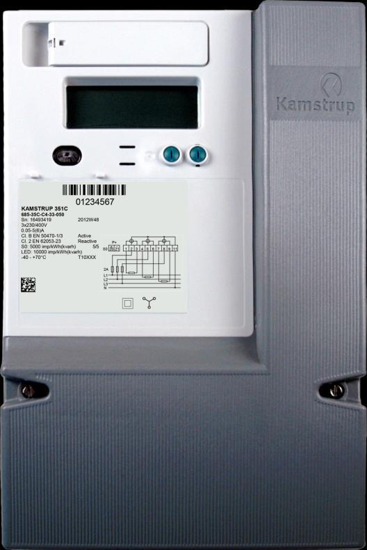
15 3.5 Connection diagrams The valid connection diagram appears from the type label on the front of the meter. OMNIPOWER Three-phase, four-wire (S0) L1 L2 L3 N S P OMNIPOWER Three-phase, four-wire (APS version) L1 L2 L3 N APS 28 OMNIPOWER Three-phase, three-wire (Aron) L1 L2 L3 N S P L1 N S0 + P Kamstrup A/S Technical Description _D1_GB_
 Connect the meter in accordance with the installation diagram on the meter s type label.")
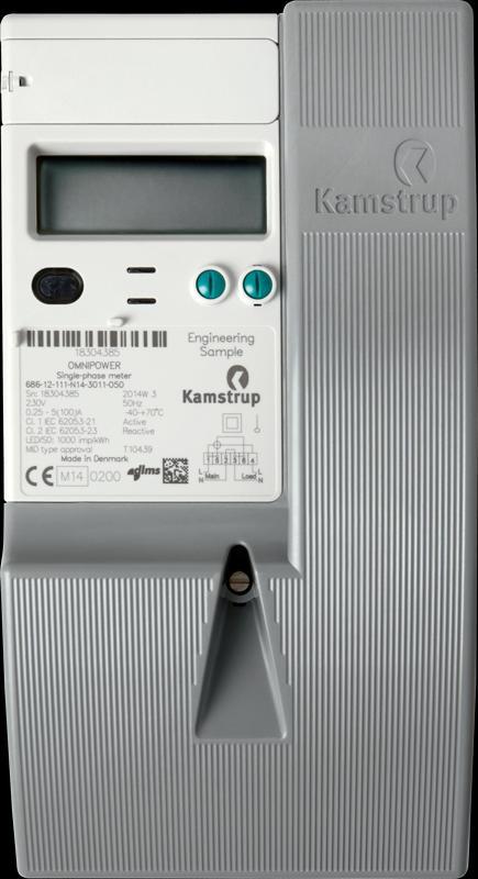
16 OMNIPOWER Single-phase, two-wire L1 N S0 + P OMNIPOWER Single-phase, two-wire Symetric terminals 21 ST-meter L1 N L1 N S0 + P S0 + P OMNIPOWER CT 3-phase, 4-wire OMNIPOWER CT 3-phase, 3-wire (Aron) Connect the meter in accordance with the installation diagram on the meter s type label. 16 Kamstrup A/S Technical Description _D1_GB_
17 3.6 Terminal numbering S0 28 APS Figure 4: Terminal numbering for OMNIPOWER three-phase meter with S0 or APS S0 Figure 5: Terminal numbering for OMNIPOWER three-phase meter with S S0 Figure 6: Terminal numbering for OMNIPOWER single-phase meter with S0. Kamstrup A/S Technical Description _D1_GB_


18 Figure 7: Terminal numbering for OMNIPOWER single-phase ST-meter with S0 Figure 8: Terminal numbering for OMNIPOWER CT-meter 18 Kamstrup A/S Technical Description _D1_GB_

19 4 How to use OMNIPOWER meters This chapter describes in details the use of OMNIPOWER, the features implemented and not least the benefits which the meter provides to the users. 4.1 Installation and power-up It is essential that the meter is installed and connected as described in Kamstrup installation manuals. See previous section for connection diagrams of the specific meter types. 4.2 Power-up/Start-up sequence The display power-up sequence is shown in Figure 9. In the first five seconds after connecting OMNIPOWER, the ROM checksum is displayed with its corresponding OBIS code. In the next five seconds, the meter shows its software type number and revision number. The value field describes the software number while the software revision is shown in the text field in the upper right corner of the display. The phase indicators L1, L2 and L3 show whether voltage is applied to each phase. The arrows indicate any direction of the power flow for each phase. Also the phase sequence is indicated. The sequence is defined in Table 1. 5 seconds Figure 9: Start-up sequence in display. Symbol Phase sequence L1-L2-L3 L1-L3-L2 Table 1: Phase sequence. After additional 5 seconds, the meter starts operational mode and begins displaying its automatic display list. If the meter is part of OMNIA Suite, the integrated radio module starts searching for a network. This is indicated by the antenna symbol that flashes. When a network is located and the meter is in contact and recognized by a concentrator, the symbol will be constantly On. It is possible to delay the start up of the integrated radio for 5 minutes if the left push button is pushed for approximately 5 seconds immediately after power is applied to the meter. The RF symbol will turn off to indicate that the start-up is delayed. The radio will automatically start searching for a radio network when the 5 minutes are passed, or immediately after a re-power of the meter. Kamstrup A/S Technical Description _D1_GB_


20 4.2.1 Display functions The OMNIPOWER provides the possibility for up to four display lists to which a number of meter values/parameters can be attached. Table 2 gives an overview of the available display lists. Display view Description Shifting Maximum values Automatic display list A list of registers that is shown automatically in the display. Automatically 10 seconds (fixed) 16 Manual consumer display list Manual utility display list Supply backup display list A list of registers that can be seen by pushing the left pushbutton on the meter front. As manual consumer display list, but this list can only be seen by pushing the sealable push-button. In case the meter is disconnected from the main supply, this display list still allows the user to read out a number of meter values. The display is only activated by pushing the left push-button. Table 2: Available display lists in OMNIPOWER. Manually via left push-button Manually via right push-button Manually via left push-button Each list can be customized at ordering, and can also be reconfigured after installation. OMNIA Suite also provides the possibility to update the display lists remotely Push-button functionalities Two push-buttons are available on OMNIPOWER meters as shown in Figure 10. The left push-button is used for manual display scrolling and manual connect/disconnect of internal breakers if the meter is configured for this. The right push-button is sealable, and the following functionalities can be enabled via configuration: Set time and date Adjust time Execute debiting stop Disable/enable optical port Change meter number Set tariff plan and load control plan Test load control relays. Figure 10: OMNIPOWER pushbuttons. Each function can be enabled independently in the setup. Configuration of the sealable push-button must be done at the time of ordering the meter. The right push-button can only be activated when the slot is in a vertical position. The button can be locked by turning it 90 to horizontal position and then mount a sealing as shown in Figure 11. Figure 11: Release of sealable pushbutton. 20 Kamstrup A/S Technical Description _D1_GB_
21 4.2.3 Tamper An OMNIPOWER meter has registration of magnetic field detection and meter cover tampering. Any registration can be accompanied by indication in the display. This indication can be configurable to be temporary (i.e. it disappears when the source to tamper disappears), or permanent until a tamper release command is received either from a smart metering system or by activating the sealable push-button. With OMNIPOWER meters implemented in OMNIA Suite, it is also possible to receive tamper registrations as push alarms to the meter data management (MDM) system Meter status logger ( ) The meter has a status logger which contains information about the meters status events. A registration in the logger can be triggered by following events: - EEPROM access failure - ROM checksum fail - Tamper detection - Magnetic field detection - Meter reset The meter status logger is circular and will therefore contain the 200 newest meter status events. 4.3 Time management The meter has an integrated real-time clock (RTC) to provide measured data with an accurate time stamp (typically 5 ppm at 23 C). The RTC is used to generate time stamps on load profile values and event registrations and to keep any tariff and load control plans on track Backup In case of power supply outage, the RTC function is supplied by either a battery or rechargeable backup unit (supercap). The backup time of the battery depends on the period of time the meter is without mains supply, and in addition, the battery gives access to further functions such as display views despite lack of mains supply. The lifetime of the backup unit also depends on the mains voltage supply to the meter and the ambient temperature Hour counters As the RTC manage the date and time in the meter, an hour counter register manages the number of operating hours of the meter, i.e. number of hours where main voltage are supplied to the meter. As a supplement to the total hour counter, the meter also contains seperate counters for all 8 tariffs available in the meter Calendar and daylight saving time plan It is possible to set up a calendar plan useable for tariff and load control. The calendar plan can contain up to 4 different seasons, and each season can have different weekly plans. How a weekly plan is divided into working days, non-working days and holidays is described in Internal tariff plan in the meter, p. 29. Kamstrup A/S Technical Description _D1_GB_
22 In addition to the regular calendar plan, a list of exceptions days can be added to the calendar. The list can contain up to 200 days 20 years ahead in time. Exceptions days will have the same tariff plan as holidays. Finally, OMNIPOWER also have an option for a daylight saving time plan which can be programmed in the meter with corresponding configuration of start and end dates for up to 20 years ahead in time. However, all time stamps in data loggers and event loggers are done in normal time and does not take eventually daylight light saving time into account RTC setting and adjustment using pushbutton It is possible to configure the meter to enable RTC setting/adjustment using the right pushbutton. The guideline on how to do this is described in 5514xxxx RTC adjustment logger ( ) The time is adjustable via the configuration program METERTOOL or via a smart metering system like OMNIA Suite. Changes are registred in a dedicated RTC adjustment logger, and if needed, the registration can be filtered to avoid insignifcant adjustments, e.g. less than 7 seconds, to fill the log. 22 Kamstrup A/S Technical Description _D1_GB_

23 4.4 Power and energy measurements Energy consumption is calculated as an expression of the current compared to the phase voltage and time. The energy registration per measuring system is communicated to the meter's legal processor via the meter's own internal bus system and is summed in the meter's main registers Power measurements OMNIPOWER are constructed as 4-quadrant meters, which means active, reactive and apparent power and energy measurements in the flow directions shown in Figure 12. W A- kwh VA var R- c R+ kvarh R+ i W VA var A+ kwh R- i R+ c VA VA W var R- kvarh Figure 12: Energy and power measurement in 4 quadrants. W var The available power registers in OMNIPOWER are listed in Table 3 with the corresponding OBIS codes according to EN Designation P+ P14 Quadrant illustration Description Active positive power consists of active power from quadrants 1 and 4. Unit Display OBIS code kw P- P23 Q+ Q12 Q- Q34 Active negative power consists of active power from quadrants 2 and 3. Reactive positive power consists of positive inductive power from quadrant 1 and positive capacitive power from quadrant 2. Reactive negative power consists of negative inductive power from quadrant 3 and negative capacitive power from quadrant 4. kw kvar kvar S+ S14 S- S23 Positive apparent power from qudrant 1 and 4. kva Negative apparent power from qudrant 2 and 3. kva Table 3: Main power registers in OMNIPOWER. Kamstrup A/S Technical Description _D1_GB_
24 All values in Table 3 are instantaneous values. They have an update frequency of 1 Hz. Additional to these instantaneous power registers, OMNIPOWER also contains a range of derived power registers, e.g. mean values and peak values. These different values are described in section and Energy registration The OMNIPOWER is available as an import/export meter for active, reactive and apparent energy. The possible energy registers are described in Table 4 with the corresponding OBIS code according to EN Designation A+ A14 A- A23 R+ R12 R- R34 R1 R+ i R2 R+ c R3 R- i R4 R- c E+ E14 E- E23 Quadrant illustration Description Active positive energy consists of active energy from quadrants 1 and 4. Active negative energy consists of active energy from quadrants 2 and 3. Reactive positive energy consists of positive inductive energy from quadrant 1 and positive capacitive energy from quadrant 2. Reactive negative energy consists of negative inductive energy from quadrant 3 and negative capacitive energy from quadrant 4. Unit kwh kwh kvarh kvarh Display OBIS code x (tariff) x (tariff) x (tariff) x (tariff) Positive inductive energy from quadrant 1. kvarh Positive capacitive energy from quadrant 2. kvarh Negative inductive energy from quadrant 3. kvarh Negative capacitive energy from quadrant 4. kvarh Positive apparent energy from qudrant 1 and 4. Negative apparent energy from qudrant 2 and 3. Table 4: Main energy registers in OMNIPOWER. kvah kvah x (tariff) x (tariff) Some of the energy registers in the table are used as the legal energy registration in OMNIPOWER. Configuration of the meter decides wich energy registers to be legal. 3 The x indicates the corresponding tariff for the energy type. 24 Kamstrup A/S Technical Description _D1_GB_
25 The legal energy registers are automatically used as values for the load profil data logger, which is described in detail in Load profile, p. 31. In addition to energy registers a number of deviated energy registers are also available in the meter. These are listed in Table 5. For OMNIPOWER CT meters registers 1.8.x, 2.8.x, 3.8.x, 4.8.x, and are available as both secondary and primary values. The secondary values can be configured for use in display and load profile logger. Designation Description Unit A1234 A+ trip A- Trip R+ trip R- Trip E+ trip E- Trip A-net = A+ - A- A 4 prepayment A 4 prepayment,credit This register sums the active positive and negative energy numerically. Can be used as a control register for a one-way (A+) meter. Resettable trip counter. Accumulates total active positive energy and resets via left push button (6 sec). Resettable trip counter. Accumulates total active positive energy and resets via left push button (6 sec). Resettable trip counter. Accumulates total active positive energy and resets via left push button (6 sec). Resettable trip counter. Accumulates total active positive energy and resets via left push button (6 sec). Resettable trip counter. Accumulates total apparent positive energy and resets via left push button (6 sec). Resettable trip counter. Accumulates total apparent negative energy and resets via left push button (6 sec). Net calculation register. Counts backwards if A- > A+. The register is useable as infomative register in the display, for installations with microgeneration, e.g. solar cells. The register is not available as a legal register in the load profile logger. Prepayment register that counts down the kwh value which is preset in the register. Used to disconnect the internal breaker when it reaches zero. Used as a credit register in case the exception time is active in the prepayment functionality. Can only be reset by adding kwhs to the meter. Table 5: Additional energy registers in OMNIPOWER. Display OBIS code kwh kwh kwh kvarh kvarh kvah kvah kwh kwh kwh Register is Not available in OMNIPOWER CT meters. Kamstrup A/S Technical Description _D1_GB_
 kwh/kvarh - 7.0 (0000000) kwh/kvarh 7.1 (0000000.0) kwh/kvarh - 7.2 (0000000.00) kwh/kvarh Table 6: Resolution for energy registers in OMNIPOWER.")
26 The resolution by which all the energy readings are shown in the display can be set to following: Display resolution Single-phase and three-phase meters CT meters 6.1 ( ) kwh/kvarh ( ) kwh/kvarh ( ) kwh/kvarh 7.1 ( ) kwh/kvarh ( ) kwh/kvarh Table 6: Resolution for energy registers in OMNIPOWER. Furthermore, it is possible to select or deselect leading zeroes. The configuration of the display resolution and leading zeros are done when ordering the meter and cannot be reconfigured afterwards due to legal requirements. Alle secondary energy registers in OMNIPOWER CT are shown with display relosution 5.2 ( ) kwh/kvarh Calculation methods of an OMNIPOWER three-phase meter OMNIPOWER provides three methods for calculating the energy in three-phase meters. Three similar meters can therefore obtain different results for energy measurement depending on the configuration of calculation method. A- A+ L1 A- A+ L1 L2 L2 L3 L3 Figure 13: Two examples of energy consumption in a three-phase meter. If energy is imported on phases L1 and L2 (shown as red), and energy is exported on phase L3 (shown as blue) as shown to the left in Figure 13, the calculation can be made according to the methods described below. Table 7 describes the different calculation methods of the total energy dependent on the applied calculation method. 26 Kamstrup A/S Technical Description _D1_GB_
27 Calculation method Phase energy consumption A- A+ Three-phase examples L1 L2 L3 Total energy registration A- A+ L1 L2 Description Individual import/export L3 A- A+ L1 A- A+ A- A+ L1 Individual import/export calculation method has one register for the positive contributions and one for the negative contributions. L2 L2 L3 L3 A- A+ Vector summation A- A+ L1 L2 L3 A- A+ L1 L2 L3 A- A+ L1 L2 L3 A+ A- A+ L1 L2 L3 A- When using vector summation, the positive contributions are added and the negative contributions are substracted in the same way as by electromechanical meters. Contributions from e.g. solar energy installations will be set off in the total energy calculation. This calculation method is sensitive to incorrect installation and manipulation. A- A+ L1 A- A+ L1 L2 L3 L2 Total summation L3 A- A+ L1 A- A+ A+ Total summation adds all contributions to the positive register whether one or more phases contributes with negative energy. L2 L1 L2 L3 L3 A+ Table 7: Calculation methods in OMNIPOWER. The configuration of the energy calculation method must be done when ordering the meter and cannot be reconfigured afterwards due to legal requirements. Kamstrup A/S Technical Description _D1_GB_
28 4.4.4 Mean power values In Table 3, the instantaneous values for different power registers in OMNIPOWER are listed. Some of these values are also available as mean values. The values are either averaged during the corresponding integration time for the load profile or during the configurable log interval for the analysis logger. Display Designation Description Unit OBIS codes P+mean P-mean Q+mean Q-mean S+mean S-mean Mean value of the positive active power during the legal integration period. Mean value of the negative active power during the legal integration period. Mean value of the positive reactive power during the legal integration period. Mean value of the negative reactive power during the legal integration period. Mean value of the positive apparent power during the legal integration period. Mean value of the negative apparent power during the legal integration period. Table 8: Mean power values in OMNIPOWER. kw kw kvar kvar kva kva The above mean values are also available for each phase L1-3, see Analysis logger p Peak power values The meter also registers the peak value for the power measurements. The measuring period of the peak calculation follows the load profile integration period. For every integration period, the mean power is calculated and then compared to the present peak value. If the new value exceeds the present value, it replaces the present value. Designation Description Unit P+max P-max Q+max Q-max Active positive power consists of active power from quadrants 1 and 4. Active negative power consists of active power from quadrants 2 and 3 (incl. Tariff 1 & 2). Reactive positive power consists of positive inductive power from quadrant 1 and positive capacitive power from quadrant 2. Reactive negative power consists of negative inductive power from quadrant 3 and negative capacitive power from quadrant 4 (incl. Tariff 1 & 2). S+max Positive apparent powery from quadrants 1 and 4. kva kw kw kvar kvar Display OBIS codes x (tariff) x (tariff) x (tariff) S-max Negative apparent power from quadrants 2 and 3. kva Table 9: Peak power values in OMNIPOWER. 28 Kamstrup A/S Technical Description _D1_GB_
29 The peak power values are reset at every debiting stop executed in the meter. See Monthly debiting logger, p. 32 for further information about debiting stop and the debiting logger Energy tariff registers OMNIPOWER contains for each main energy registers; A+, A-, R+, R-, E+ and E-, up to 8 deviated tariff registers. The use of tariff registers enables the possibility for time-segmentation of the total energy consumption, relevant when electricity is prize differentiated according to the time of use during a day, week or season. Which tariff that is to be active, can be controlled in three different ways: by hardware using a 230 VAC input signal by an on demand remote command sent from a smart metering system by an internal tariff plan configuration in the meter These options are described in the following sections Hardware-controlled 230 VAC input A list of available Kamstrup modules for OMNIPOWER includes a 230 VAC input that provides a 2- or 4-tariff control option. The modules are: Tariff stand alone (4-tariff) M-Bus module (2-tariff) RS485 module (2-tariff) Module I/O-controlled tariffs use the ports of the module connector for changing the tariffs, e.g. if a tariff control module prepared for 230 VAC is connected to 230 VAC. The inverted function can also be selected. The control table is shown in Table 10. Port 1: Terminals 13 and 15 Port 2: Terminals 33 and 15 Active tariff 0 VAC 0 VAC T1 T4 230VAC 0 VAC T2 T3 0 VAC 230VAC T3 T2 230VAC 230VAC T4 T1 Table 10: Tariff control table. Active tariff inverted Whether or not the active tariff is inverted, it is configured as part of the meter order form (SW-software configuration parameter Z3) On demand system-controlled With OMNIPOWER connected to a smart metering system, the actual tariff can be set by a single remote command Internal tariff plan in the meter An OMNIPOWER meter can contain up to three different tariff plans which can be selected on-site via the user interface (i.e. the sealable push-button) or remotely e.g. via OMNIA Suite. Kamstrup A/S Technical Description _D1_GB_
30 Exceptions days plan OMNIPOWER direct and CT meters Each tariff plan can have one, two, three or four different season plans available. In one year, the meter can shift up to 8 times between the available season plans. Each season plan consists of one, two or three types of days: Working days, Non-working days, Holidays. A daily tariff plan can finally be made individually for each of the three different types of days. The tariff plan setup is illustrated in Figure 14. OMNIA suite User interface 3 x Tariff plans 4 x season plans up to 8 start dates 3 x daily plans up to 10 tariff shifts Figure 14: Tariff plan setup for OMNIPOWER. A daily tariff plan in the meter can contain up to 10 tariff shifts per day and the resolution of the shifting is 1 minute. 30 Kamstrup A/S Technical Description _D1_GB_
31 4.5 Data loggers OMNIPOWER has a number of different data loggers: Load profile logger (15 minutes, half-hourly or hourly energy logger) Monthly debiting logger daily, weekly or monthly debiting logger Analysis logger. The loggers are different regarding the number of registers to be logged, the time interval between logs and the configuration possibilities. Each logger is described in the following. Notice!! All time stamps in data loggers are done in normal time and does not take eventually daylight light saving time into account Load profile ( ) The load profile logger is based on energy readings where the types of energy to be logged are based on the meter configuration selected when ordering the meter. The load profile in OMNIPOWER is implemented according to WELMEC software guide The integration period of the meter is changeable and can be set to 15, 30 or 60 minutes. The period can be reconfigured after installation. Depending on the chosen integration period and the number of energy types to be measured, OMNIPOWER contains a number of log entries which are converted to a number of days and listed in Table 11. For OMNIPOWER CT meters the meter can be ordered to register either secondary or primary values in the load profile logger. This cannot be reconfigured afterwards. Energy type Integration period 15 min. [Days] 30 min. [Days] 60 min. [Days] A A+/A A+/R A+/R A+/A-/R+/R Table 11: Logging depth of load profile logger. Each log entry is also marked with a status marking, which is also implemented according to WELMEC It contains information regarding the quality of each specific log entry, e.g. any voltage outage, over voltages and under voltages and any eventually RTC adjustments executed during the integration period. 5 Variant 2 meters has extended logging depth of 180 days of 15 min values. Kamstrup A/S Technical Description _D1_GB_
32 4.5.2 Monthly debiting logger ( ) OMNIPOWER has a debiting logger where the instantaneous values of a number of predefined registers are logged every time a debiting stop is executed. The predefined registers that are part of the debiting logger are listed in Table 12. Various OBIS codes Energy registers OBIS codes Power registers OBIS codes RTC w/quality Active energy A P+max Active energy A P+max RTC Hour counter Reactive energy R Accumulated P+max Number of debiting periods Reactive energy R Accumulated P+max Tariff Power threshold A+ Tariff x.255 Accumulated P+max counter Tariff 2 Pulse input R+ Tariff x.255 Q+max Current Apparent energy E Q+max RTC transformer ratio 6 Apparent energy E Accumulated Q+max Table 12: Registers stored in debiting logger. P+max Tariff P+max Tariff 1 RTC P+max Tariff P+max Tariff 2 RTC Q+max Tariff Q+max Tariff 1 RTC Q+max Tariff Q+max Tariff 2 RTC S+max S+max RTC S-max S-max RTC The interval between each debiting stop/debiting log can be controlled by the meter and can be set to make an automatic log of the registers every month, every second month, every third month, every half year or once a year. The debiting stop can also be done on request, either by a command from an MDM system like OMNISOFT VisionAir or manually by using the sealable push-button if the meter is configured accordingly. The maximum number of log entries in the meter is 36. When this number of logs has been reached, the meter overwrites the oldest entries. 6 Register in OMNIPOWER CT meter only. 32 Kamstrup A/S Technical Description _D1_GB_
33 4.5.3 Daily/weekly/monthly debiting logger ( ) In the same way, OMNIPOWER also contains a daily or weekly based debiting logger. The registers that are logged are listed in table 13. Various OBIS codes Energy registers OBIS codes RTC w/quality info Active energy A Active energy A Hour counter Reactive energy R Reactive energy R Active energy A+ Tariff x.255 Active energy A- Tariff x.255 Reactive energy R+ Tariff 1-4 Reactive energy R- Tariff x x.255 Table 13: Registers stored in debiting logger 2. The interval between each debiting stop is controlled by the meter and must be set to either daily or weekly logging. There are no possibilities for executing a debiting stop on request for this logger. The maximum number of entries in the logger is Analysis logger ( ) The analysis logger allows you to configure the registers to be logged and the log interval: Up to 16 different registers Changeable log intervals: 5, 15, 30 or 60 minutes independent of load profile settings. Registers OBIS Codes Pulse input Hour counter Active energy A Active energy A Reactive energy R Reactive energy R Reactive energy R Reactive energy R Reactive energy R Reactive energy R A+ Tariff x.255 A- Tariff x.255 R+ Tariff x.255 R- Tariff x.255 Active energy A Active energy A+Net Apparent energy E Apparent energy E Actual power P Actual power P Actual power Q Actual power Q Power Factor Avg P+ L1, P+ L2, P+ L3 P- L1, P- L2, P- L3 Q+ L1, Q+ L2, Q+ L3 Q- L1, Q- L2, Q- L3 S+ L1, S+ L2, S+ L3 S- L1, S- L2, S- L3 Registers OBIS Codes Cut-off state P+ max, daily P+ min., daily P+ max, daily RTC P- min.,daily RTC I L1, I L2, I L3 U L1, U L2, U L3 PF L1, PF L2, PF L3 THDU L1, THDU L2, THDU L3 THDI 7 L1, THDI 7 L2, Registers OBIS Codes THDI 7 L3 Frequency Table 14: Registers available for analysis logger. 7 Not in OMNIPOWER CT meters Kamstrup A/S Technical Description _D1_GB_
34 A+ A+/A A+/R+ A+/A-/R+/R- A+ A+/A A+/R+ A+/A-/R+/R- The logging depth of the analysis logger depends on the log interval and the number of registers in the analysis logger. The meter is preconfigured from factory regarding the registers to be logged and the interval by which they are logged, but these settings can be reconfigured. The log interval is default set to 15 min. An example of the default setup of the analysis logger can be seen in Table 15. Meter type OMNIPOWER single-phase OMNIPOWER three-phase Registers in the load profile logger Default registers in the analysis logger 1 register 2 registers 4 registers 1 register 2 registers 4 registers Actual power P+ X X X X X X X X Actual power P- X X X X Actual power Q+ X X X X Actual power Q- X X Average voltage L1 X X X X X X X X Average voltage L2 X X X X Average voltage L3 X X X X Average current L1 X X X X X X X X Average current L2 X X X X Average current L3 X X X X Logging depth of analysis logger [Days] Table 15: Default setup for analysis logger. Mean phase voltage and mean phase current are calculated as the mean value during the log interval period configured for the analysis logger. Phase currents are shown as absolute values without indicating the direction of the current.
35 4.6 Meter readout The OMNIPOWER meters offer a range of options regarding meter data readout. It spans from simple display reading to advanced remote readout for smart metering systems Manual display readout The display can show all relevant meter data, e.g. power and energy, phase currents and voltages, meter number etc. etc. Even the load profile and the debiting logger can be read out in the display. The complete design of available segments in the display is shown in Figure digit identification field OBIS-field Quadrant reading Module indication Text field + Q -P - Q +P M1 M2 M3 M4 Value field Phase current indication L1 L2 + - L3 + T! var z Unit field Figure 15: OMNIPOWER display. In the following sections, the different display segments are described digit value field This field is used for displaying all kind of register values. Meter energy is stated in [6.1], [6.3] [7.0] or [7.2] format with either kwh or kvar as unit. Power is shown with [2.3] format (00.000) and either kw or kvar as unit. Date/time can also be shown in the display and is stated according to the formats YYYY:MM:DD and HH:MM:SS respectively. In both cases without any units shown. Register values like meter number, special data, etc. are indicated by 8 digits also without any unit. The value field can be configured to display leading zeroes of all energy readings. What to be shown in the value fields depends on the configuration of the display. The configuration of the display is explained further in section 5.4. The display showing can also be remotely updated after installation of the meter with the OMNISOFT VisionAir MDM system Unit field Mains voltage reading Phase sequence symbol Tariff reading Errorsymbol prepaymentsymbol The unit field is used for displaying the units of registers in the value field. Breakersymbols Tamper symbol RFsymbol Kamstrup A/S Technical Description _D1_GB_
36 Object identification field Field for identifying the value in the value field. OBIS codes are used in connection with the identification Quadrant reading The total current load is indicated by the arrows for +P (imported active power), -P (exported active power), +Q (inductive reactive power) and Q (capacitive reactive power), respectively. The quadrant reading is an instantaneous total value for all three phases. The reading is not active when the load is below the minimum limit of 10 ma RMS. It is configurable whether the quadrant indication shall be visible in the display Text field The text field is used either for additional information about the unit field regarding values in the value field or for text information. In the latter case, text messages are shown as scrolling text in the field Module indication Indicates whether a module is communicating with the meter, and in this case which module, e.g. internal radio, primary module or CCC-module (However, this feature is not yet activated) Error symbol Only used internally by Kamstrup Breaker symbol 8 If the meter is configured with an internal breaker, the position of the breaker is indicated as either connected or disconnected. However, if the smart disconnect functionality is disabled, both symbols are off Tamper symbol Indicates either a magnetic field near the meter or if the meter cover has been removed from the meter Radio network symbol If a meter is to be used in an OMNICON Radio Mesh Network, the symbol indicates the meter s connection status with the network Prepayment symbol 8 The symbol indicates whether the prepayment functionality is activated Tariff indication The tariff indicator can show T1, T2, T3, T4, T5, T6, T7 and T8 to indicate the currently active tariff. The tariff reading is updated every 10 sec., i.e. it may take up to 10 seconds from a tariff shift has been carried out until the current tariff is displayed. The tariff indication is switched off if display configuration without tariff reading has been selected. 8 Not available for OMNIPOWER CT meters 36 Kamstrup A/S Technical Description _D1_GB_
37 Mains voltage reading The mains voltage readings per phase L1, L2 and L3 indicate whether voltage is applied to the individual phase input terminal or not. Indications L1, L2, L3 On Off Indicate The voltage is above minimum limit (160VAC). The voltage is below minimum limit (160VAC). Table 16: Main phase voltage indication. The minimum voltage limit is 160 VAC 5 %. If the voltage remains below minimum limit for more than 1 second in all phases, the processor shuts down and the meter is reset Phase current indication The direction of the current for each phase is shown with these indicators. It can be useful when checking if inputs and outputs have been installed correctly. Indications - + Indicate On Off The load is above minimum limit. The load is below minimum limit. Table 17: Phase current indication. The minimum load limit for phase current indication is approx. 2.3 W (0.6W for OMNIPOWER CT meters). If the phase current is lower than this value, energy registration stops, and the phase current indication turns off in the display Phase sequence indication This shows the phase sequence of the input phases. If both symbols are off, this indicates that no sequence could be clearly recognized. The reason could be that one or two phases are missing on the input Protocols A number of communication protocols are available with OMNIPOWER. Kamstrup Meter Protocol DLSM/COSEM EN (1107) Mode A & C Kamstrup Meter Protocol (KMP) KMP is a communication protocol that is suited for communication with OMNIPOWER. It gives access to all registers in the meter and enables programming and setup. Please contact Kamstrup A/S for further information about this protocol. Kamstrup A/S Technical Description _D1_GB_
. Please contact Kamstrup A/S for further information about this protocol for OMNIPOWER meters. 4.6.3.")

. This tool is also suitable for configuration of the meter. For more information about METERTOOL OMNIPOWER, please contact KAMSTRUP A/S. 4.6.")

38 DLMS The DLMS protocol gives access to most registers and loggers in the meter and to the most of the configuration options as well. See DLMS Protocol description (document no: ). Please contact Kamstrup A/S for further information about this protocol for OMNIPOWER meters The 1107 protocol gives access to most registers in the meter and enables configuration and setup, see IEC 1107 Protocol description (document no: ). Please contact Kamstrup A/S for requesting the 1107 protocol for OMNIPOWER meters Local readout via optical interface METERTOOL OMNIPOWER It is possible to read out all meter relevant data via the optical interface with Kamstrup s METERTOOL OMNIPOWER, see Installation and Users Guide (document no: ). This tool is also suitable for configuration of the meter. For more information about METERTOOL OMNIPOWER, please contact KAMSTRUP A/S Integrated OMNICON radio mesh connectivity Meters can be delivered with integrated OMNICON radio mesh connectivity. When connected to the OMNIA smart grid platform, the full range of advanced features becomes available Integrated OMNICON point-to-point connectivity Meters can be delivered with OMNICON point-to-point connectivity modules as shown in figure below. When connected to the OMNIA smart grid platform, the full range of advanced features becomes available. Figure 16: Point-to-point communication in OMNIA Suite. 38 Kamstrup A/S Technical Description _D1_GB_
39 The communication module can be delivered pre-mounted in the meter, or it can be mounted after the meter is installed. The post-mounting of the modules can be done without removing the power to the meter terminal connection Full encryption on all interfaces OMNIPOWER meters with SW no or introduce full data encryption on all communication interfaces including the primary module port, CCC module port and the optical interface. The encryption method used is AES 128-bit and it covers read out of all consumption/production data, read and write possibilities of configuration parameters and control commands like disconnect/reconnect of the internal breaker. Kamstrup OMNIA Suite supports full read out, configuration and control of encrypted OMNIPOWER meters. For 3 rd party MDM systems to be able to support encrypted meters, it is required that the systems connect to Kamstrups KMS (Key Management Service), which will allow the MDM to access all unique encryption keys for the relevant meters. For more information about encrypted meters and KMS, please contact Kamstrup A/S M-Bus and RS-485 connectivity Meters can be delivered with M-Bus or RS-485 connectivity modules. The M-Bus module communicates through the EN /3 protocol. The RS-485 module can be used with the KMP, DLMS and 1107 protocols. 4.7 Modularity options OMNIPOWER meters have two independent module areas available for communication. Both module areas are per default available on all OMNIPOWER meter types Primary modules The primary module area can be used for communication modules as described in the previous section, but it can also be used for tariff control modules, load control modules, etc CCC modules The second module area, which is shown in Figure 17, offers access to the Consumer Communication Channel (CCC). Figure 17: CCC-module area in OMNIPOWER. Kamstrup A/S Technical Description _D1_GB_

 The following description applies to OMNIPOWER direct meters with integrated breakers. Meters with integrated breakers can disconnect and reconnect the consumer s supply.")

40 CCC-modules are intended for in-home communication as shown in Figure 18. The communication can be one way to e.g. an in-home display, or it can be two-way for intelligent control of e.g. relays in the home. CCC-modules also enable the utilities to send consumer-related information, e.g. price signals to in-home displays directly from their MDM or other business systems. Figure 18: CCC-module in OMNIA Suite. A suitable technology for in-home communication is ZigBee Smart Energy or similar. 4.8 Disconnect functionality ( ) The following description applies to OMNIPOWER direct meters with integrated breakers. Meters with integrated breakers can disconnect and reconnect the consumer s supply. All meters with integrated breaker are marked on th efront of the meter as shown the figure. The breaker is controlled by the meter s main processor and is bistable, i.e. it maintains its status, i.e. connected/disconnected, independently of the main supply status of the meter. The integrated breaker disconnects all the output phases in the meter while the neutral connection is not disconnected. Note!! The breaker must not be used for safety cut-off. 40 Kamstrup A/S Technical Description _D1_GB_

41 For both OMNIPOWER three-phase and OMNIPOWER single-phase meters, the integrated breakers are approved according to EN , Annex C for UC3 breaking capabilities. This means that the meter fulfills following: makes-and-breaks 100A PF=1.0 and PF=0.5 inductive) Shortcircuit current carrying capacity 6kA/3kA (Test1/Test2) The UC3 approval documents can be handed out by Kamstrup on request Disconnect function in the meter The meter can be delivered with integrated breakers. It is possible to disconnect the breaker in four ways: Manually by activating the left push-button Remotely from a smart metering system By smart disconnect intelligent disconnection when voltage, current or power exceeds a preconfigured limit By the integrated prepayment option. When the breaker is disconnected, it is possible to reconnect the breaker in four ways: Manually by activating the left push-button Remotely via a release command and an additional reconnect command With a combination of a release command sent from a smart metering system and a manual reconnect on the push-button. Automatically after current and power level are back to normal or credit (if prepayment is activated) is restored. Indenpendently of the way of reconnect, the reconnection time is minimum 5 seconds. It is configurable which of these options are available in a meter. In the following sections, the different control options are described in details Manual disconnection and reconnection It is possible to disconnect the breakers manually. This is done in the following way: 1. On the meter, select the shown display reading by activating the left push-button. +Q +P 2. Activate the left push-button for approx. 6 seconds. This disconnects the relays, and the red LED turns on L1 L2 L3 Manual reconnection is done in the following way: 3. On the meter, select the primary display reading when the red LED is flashing. 4. Activate the left push-button for 6 seconds until the relays are connected and the red LED turns off. Kamstrup A/S Technical Description _D1_GB_
42 4.8.3 Remote disconnection from a smart metering system OMNIPOWER meters with integrated breakers can also have their breakers disconnected, released and reconnected remotely. As a safety precaution, the remote disconnect functionality in OMNIA Suite is encrypted by encrypted communication Smart disconnect The meter includes a smart disconnect feature that disconnects the breakers if either the total current or power exceeds a preconfigured limit Disconnection basis The choice of disconnection basis setup decides if smart disconnect is enabled or disabled, and on which basis the smart disconnect is effected if enabled. It is possible to select: No function: The smart disconnect function is disabled. Current-controlled: Smart disconnect is effected when a configured current limit is exceeded. Power-controlled: Smart disconnect is effected when a configured power limit is exceeded. Voltage controlled: Smart disconnect is effected when a configured phase voltage limit is exeeded. Prepayment: The prepayment function controls the disconnection. The disconnection basis is selected as part of the smart disconnect configuration. Per default, the meter is provided with the smart disconnect functionality disabled. If the function is to be used, it can be enabled from the factory at delivery, it can be activated remotely or locally with METERTOOL OMNIPOWER Current-controlled disconnection Current-controlled disconnection is based on RMS current with average calculation every 1 second. Disconnection is effected if one of the phase currents I L1, I L2 or I L3 exceeds the limit I d *k x for a configured time period; t 1, t 1 +t 2 or t 1 +t 2 +t Power-controlled disconnection Power-controlled disconnection is based on the total power in all phases. Disconnection is effected if the total phase power exceeds the limit I d *k x for a configured time period; t 1, t 1 +t 2 or t 1 +t 2 +t 3. At smart disconnect configuration, the disconnect current I disconnect (I d ) or the disconnect power P disconnect (P d ) is set, and it must be determined whether the smart disconnect is to be based on either current or power. The breaker then disconnects the supply when I d or P d is exceeded. OBIS Code Register Min. value Max value I disconnect 0 A 80 A P disconnect 0 kw 80 kw Table 18: Configuration limits for smart disconnect Delayed disconnection The meter can be configured to delay the disconnection and to differentiate the disconnection characteristics. This is done with configurable multiplication factors for both time : t 1, t 2, t 3 and current/power factors: k 1, k 2, k Kamstrup A/S Technical Description _D1_GB_
![OBIS Code Register Min. value Max value 1.1.128.0.2.255 1.1.128.0.3.255 1.1.128.0.4.255 1.1.128.0.5.255 1.1.128.0.6.255 1.1.128.0.7.255 k 1, k 2, k 3 t 1, t 2, t 3 [sec.] 0 9.](/docs-images/91/107594172/images/43-0.jpg "9 0 65535 Table 19: Multiplication factors for smart disconnect.")
43 OBIS Code Register Min. value Max value k 1, k 2, k 3 t 1, t 2, t 3 [sec.] Table 19: Multiplication factors for smart disconnect. The following conditions for the factors must be met at configuration: t 1 =< t 2 =< t 3 and k 3 =< k 2 =< k 1 The meter disconnects the supply if one of the below conditions is met for current or power, respectively. Current Power I > I d * k 3 and t > t 1 + t 2 + t 3 P > P d * k 3 and t > t 1 + t 2 + t 3 I > I d * k 2 and t > t 1 + t 2 P > P d * k 2 and t > t 1 + t 2 I > I d * k 1 and t > t 1 P > P d * k 1 and t > t 1 Table 20: Disconnect conditions for OMNIPOWER. The condition in Table 20 is also illustrated in Figure 19. P (kw), I (A) K1*P d, K1*I d K2*P d, K2*I d K3*P d, K3*I d P d, I d t 1 t 1 + t 2 t 1 + t 2 + t 3 t Reconnection Figure 19: Differentiation of smart disconnection. Reconnection can be configured to be either manual or automatic. In OMNIPOWER meters that are part of a smart metering system, the meters can be configured to allow manual reconnection provided that the meter is first released for manual reconnection by the utility. The meter is released by sending a remote command to the meter Overvoltage disconnection In addition to the smart disconnect functionality, OMNIPOWER meters also offers an option for automatic disconnect in case of an overvoltage on one or more phases. The overvoltage disconnect and reconnect are based on average values of the phase voltages and the activations can therefore be delayed by configuration of the Kamstrup A/S Technical Description _D1_GB_
44 sample time parameters called Sample-time disconnect and Sample-time reconnect. Also the voltage thresholds for disconnect and reconnect are configurable. In the example showed in figure 20 the four configuration parameters are set to following values. - Over voltage disconnect level: 270V - Over voltage reconnect level: 260V - Over voltage sample-time for disconnect: 2 sec. - Over voltage sample-time for reconnect: 5 sec. U Time of Disconnect 5 sec. 270V 260V 230V 2 sec. Time of Reconnect t Figure 20: Example of over voltage disconnect and reconnect. The configurations parameters have the range and resolution as given in ttable 21. OBIS Code Parameter Value range (resolution) Over voltage disconnect threshold V (1 V) 285V Over voltage sample time for disconnect sec (1 sec) 1 sec Overvoltage reconnect threshold V (1 V) 265V Over voltage sampletime for reconnect sec (1 sec) 60 sec Table 21: Overvoltage disconnect configuration parameters. Default value The overvoltage disconnect functionality is per default deactivated and can be activated using an AMR system or using METERTOL OMNIPOWER Disconnection on meters with APS On an OMNIPOWER meter with auxiliary power supply (APS), the disconnection functionality differs from the description in the previous chapters. If an OMNIPOWER meter with APS is supplied by main terminals L1, L2 and L3, the functionality is the same as mentioned earlier, but when this meter is supplied from the APS input, no breaker activation is possible, neither disconnection nor reconnection. 44 Kamstrup A/S Technical Description _D1_GB_

45 Event logger for disconnect/connect history ( ) A meter with breaker includes a logger that registers all events that are related to the disconnect functionality. For each event, that be a disconnection, a release or a reconnection, the meter logs an ID, a timestamp, the disconnect state and the connection feedback. The size of this logger is 200 logs Prepayment The prepayment functionality is to be used with a smart metering system. Prepayment is only possible for meters with internal breaker and will not work together with tariffs. The prepayment function is per default disabled, but can be activated and deactived as required Prepayment principle Prepayment is based on the specific prepayment register A 14prepayment. When enabling the prepayment functionality, A 14prepayment must be loaded with a number of kwh. This can only be done by using a system that supports the functionality. As soon as the register contains a number of kwh and the functionality is enabled in the meter, the register starts counting down as the energy is consumed. When A 14prepayment has reached 0 kwh, the supply is disconnected, and a new value for the register must be programmed. When prepayment is activated, the prepayment register A 14prepayment must be activated in the display settings by activating a display setup that includes the prepayment register. If a display setup with the prepayment register is activated, the register is however only shown when prepayment is enabled. When prepayment is activated in the meter, the PP symbol is indicated in the display as shown in figure. Figure 21: The PP symbol shown in the meter display. The unit in the display is kwh, and PAY is shown in the text field. The prepayment is based on total energy consumption and do not support tariffs. Therefore, the functionality is disregarded if the meter is configured for tariffs. A 14prepayment can be configured to disconnect only on working days, i.e. not on non-working days, holidays or exception days. It is also possible to set a time slot, e.g. from 10:00 PM to 8:00 AM the following day where disconnection will not happen. If A 14prepayment reaches zero within one of the above mentioned exceptions, the disconnection happens on the next working day. In the meantime, the credit register A 14prepayment,credit starts registering the energy that is consumed until disconnection takes place. When adding new kwh to the meter, the meter takes any consumption in the Kamstrup A/S Technical Description _D1_GB_
46 credit register into account. The meter subtracts the value in A 14prepayment,credit from the added amount of kwh and put the remaining kwh in A 14prepayment. If A 14prepayment has reached 0 kwh, and the breakers are disconnected, it is possible to reconnect under certain conditions. First, the load must be decreased below a defined limit called I exception or P exception. The limits are configurable within the range given in Table 22. After the load is limited, it is possible to reconnect the meter and by that still be able to use a minimum of power. Be sure to keep the consumption below the limit, or the meter will disconnect again. The duration in which the exception for current and power, respectively, can be active is however limited by a configurable number called t prepayment. When the limit is exceeded, the consumer is disconnected until new kwh are added to the meter. In the intervening period, the consumed energy is also registered in A 14prepayment,credit. OBIS Code Register Min. value Max value I exception 0 A 80 A P exception 0 kw 80 kw t prepayment days Table 22: Configurable parameters for smart disconnect. 46 Kamstrup A/S Technical Description _D1_GB_
47 4.9 Power quality measurements OMNIPOWER meters are equipped with a supply power quality measurement tool. It is based on the requirements in EN50160 regarding power quality delivered from utilities and includes the measurement of the following: Frequency variations Long-term and short-term over voltage and under voltage Power outages Rapid voltage change Supply voltage unbalance Total harmonic distortion (THD) Neutral fault detection Power factor. In the following, these quality measurements are described. Power quality detection and registration in OMNIPOWER is based on events, i.e. information is only registered if an unexpected situation appears. Some events are registered with detailed information like time stamp and voltage level information, while other events are registered as a counting number in an occurrence counter Frequency measurements Normally, frequency variations will not be relevant as most grids are synchronous connected to an interconnected grid-system, but in special cases where the grid is isolated, frequency measurements are relevant. OMNIPOWER measures a 10-second mean value of the line frequency and compares this value with the boundaries given in EN The total number of events where this 10-second mean value is outside the boundaries is registered in the occurrence counter in the meter. It is also possible to include the line frequency in the analysis logger, where the meter will log an average value according to the log interval configured for the analyses logger Voltage variations OMNIPOWER continuously (every second) updates the supply voltages at each phase and detects and registers any deviations from a set of user defined voltage limits, i.e. a deviation can be either an over voltage or an under voltage Long-term deviations Long-term deviations are related to a mean value of the phase voltage. Therefore it is also called mean time deviation. The average time, U time-period,mean is configurable in the span from 10 seconds and up to 30 minutes. The mean value is calculated for every window and for each time the value is outside the boundaries, i.e >U high,mean or < Ulow,mean, the event is registered in the voltage quality logger. Figure 22 shows an example of a phase voltage that varies in time. In this period the average time is set to 10 seconds and the first and the third period is registered as deviations. Kamstrup A/S Technical Description _D1_GB_

48 Mean value is below the min. level. Logging shall be done Mean value inside the level. No logging Max. value U high, mean 230V U low, mean Max. value Min. value Mean value is above the max. level. Logging shall be done Mean voltage Min. value Figure 22: Example of long-term voltage deviation. Average time period is 10 second. A long-term deviation is registered in the voltage quality logger in form of a time stamp (start time), a mean value, a maximum value and a minimum value for the period Short-term deviations OMNIPOWER also detect and register deviations that last shorter than the average time for mean value deviations, described in section This is described as short-term or single value deviation. Three examples of short-term voltage deviations are shown in Figure 23. In a case where the voltage is out of boundaries for several seconds the first value, the maximum/minimum value and the last value is registered. Every value is registered with a time stamp. Logging Logging Logging U high, sv 230V Single values are below the minimum voltage level L1 U low, sv Single values are abow the maximum voltage level Logging Logging Logging Logging Figure 23: Example of short-term voltage deviations. Deviations that last shorter than 1 second is registered as sags and swells, which is described in section Voltage outage OMNIPOWER detects all voltage outages, whether they are happening on one, two or three phases and all events are registered in the voltage quality logger as two events; one for outage of the voltage and one for reestablishment of the voltage. The voltage detection level depends on the event. If the outage is on one or two phases (i.e. the meter is still powered by the third phase) the registration level is a configurable value between V. If the power outage is all phases, the detection level is approximately 160 V. The detection levels are illustrated in Figure Kamstrup A/S Technical Description _D1_GB_
49 U Un = 230 V L1 L2 & L3 Detection level for voltage outage on all phases ~160V Detection level for one phase voltage outage U outage_level t Figure 24: Detection levels for one phase and three phase voltage outage. It is possible to configure the time the voltage outage shall be present before the event is logged. The value can be configured in the interval 0 second 30 minutes. All detected voltage outages are also registered in one of two occurrence counters that register the number of voltage outages. According to EN50160, voltage outages are divided into short voltage outages ( 3 minutes) and long voltage outages ( 3 minutes) and every voltage outage is registered in one of the two categories Configuration of power voltage measurements The voltage quality measurements requires, as described in the previous sections, that a list of configurable parameters are set. The list is given in Table 23 and Figure 25 shows the visual function of the parameters. Parameter Description Maximum value U high,mean Minimu m value Default value Voltage level for over voltage detection according to mean voltage deviation (in +% of nominal voltage). 276 V +20% V +1% 253 V +10% U low,mean Voltage level for under voltage detection according to mean voltage deviation (in % of nominal voltage) V -1% 184 V - 20% 207 V -10% U time-period,mean The time period for calculating the mean voltage. 10 sec. 30 min. 10 min. U low,sv Voltage level for over voltage detection according to short-term deviation (in +% of nominal voltage). 276 V +20% V +1% 253 V +10% U low,sv Voltage level for under voltage detection according to short-term deviation (in -% of nominal voltage) V -1% 184 V - 20% 207 V -10% U outagelevel The voltage level for a voltage outage that happens on 160 V 50 V 50 V one or two phases (for three-phase meters) U outage,timethreshold The time that a voltage outage has to be present before it is registered in the voltage quality logger. 0 sec. 30 min. 10 sec. Table 23: Configurable parameters for voltage quality measurements. Kamstrup A/S Technical Description _D1_GB_

50 U U high,sv U high,mean U n = 230 V U low,mean U low,sv ~160V U outagelevel t U outage, timethreshold U time-period,mean Figure 25: Configurable parameters for voltage quality measurements. The parameters can be configured remote using an AMR system or locally using METERTOOL OMNIPOWER Voltage sags and swells with a duration 100 ms 1 second. OMNIPOWER also detects and registers the number of voltage sags (or dips) and voltage swells, which are events where phase voltage drops below 20% of U n or rise above 20% of U n for a period shorter than 1 minute. Sags and swells that last for more than 1 second are registered in the voltage quality logger as described in section Sags and swells that last from 100 milliseconds to 1 second are detected and registered in one of two occurrence registers. Voltage sags and swell are not registered with time stamp or any indication of voltage level. Instead the number of each event is registered in the meter. OMNIPOWER can only register 1 sag and swell per second Rapid voltage change A rapid voltage change is defined as a change in the phase voltage within the boundaries set for over voltage and under voltage detection. For OMNIPOWER a rapid voltage change is defined as a change of %5 or more, between two subsequent samples of the phase voltage i.e. V > 11.5 V. Every rapid voltage change is registered in an occurrence counter register and this register is logged in the occurrence counter logger Supply voltage unbalance Supply voltage unbalance is a number for the balance between the three phase voltage according to voltage level for each phase and the phase shift between the three voltages. EN50160 describes that the supply voltage unbalance must not exceed 2 % when calculated as a 10-minute mean value. The OMNIPOWER meter continuously measures the supply voltage unbalance, and if the mean value exceeds the limit, the event is registered in an occurrence counter register and the register is logged in the occurrence counter logger. 50 Kamstrup A/S Technical Description _D1_GB_

51 4.9.7 Total harmonic distortion (THD) The OMNIPOWER meters also measures the THD (current THDI 9 and voltage THDU) for each phase. According to EN50160, a 10-minute mean value for THDU for each phase is calculated, and if one of these values exceeds 8 %, which is the maximum limit in EN50160, the event is registered in an occurrence counter register for the specific phase. The calculation of THD includes up to the 40 th harmonics. In total OMNIPOWER have 6 occurrences counter registers for THD, one for THDU and one for THDI for each phase. All six registers are logged in the occurrence counter logger. Both THDU and THDI is also available in the analysis logger for continuously logging of the mean value according to the integration period for the analysis logger Readout of the power quality measurements As described in the last sections, the OMNIPOWER meter continuously make a number of power quality measurements. The result of the measurements are registered in two loggers, 1. A voltage quality logger: Logs over voltage, under voltage and voltage outage events. 2. An occurrence counter logger: Logs the number of events of different power quality parameters. In this section is given some examples on the information that the two loggers provide when they are read out from the meter Voltage quality logger ( ) To show what and how the information is registered in the power quality logger, some figures from earlier sections are reused. In Figure 26 is shown how the mean voltage is calculated in terms of a 10-second sample period. Normally the sample period will be higher, e.g. 1 minute or 10 minute. U high, mean 230V U low, mean Mean value is below the min. level. Logging shall be done Max. value Mean value inside the level. No logging Min. value Mean value is above the max. level. Logging shall be done Max. value Mean voltage Min. value Figure 26: Example of long-term voltage deviations. 9 THDI is Not availeble in OMNIPOWER CT meters. Kamstrup A/S Technical Description _D1_GB_
52 For the example in Figure 26 the corresponding information in the logger is given in Table 24. For every period the mean value is outside the boundaries, there is a log entry. Log ID Time Phase Event Mean Value Max Value Min Value 1 13:50:10 (Start time) 1 (L1) 0 (Under voltage) :50:30 (Start time) 1 (L1) 1 (Over voltage) Table 24: Examples of a registration of long time voltage deviations in the voltage quality logger. Similar we can see at different short-term voltage deviations in Figure 27. Logging Logging Logging U high, sv 230V Single values are below the minimum voltage level L1 U low, sv Single values are abow the maximum voltage level Logging Logging Logging Logging Figure 27: Example of short-term voltage deviations. An example of the corresponding information in the read out is given in Table 25. For every period where several values are outside the boundaries, the first value, the minimum/maximum value and the last value is registered. Log ID Time Phase Event Mean Value Max Value Min Value 3 14:32:17 1 (L1) 6 (Single value min Start) :32:19 1 (L1) 2 (Single value min Peak) :32:20 1 (L1) 7 (Single value min Stop) :32:27 1 (L1) 6 (Single value min Start) :32:34 1 (L1) 8 (Single value max Start) :32:39 1 (L1) 3 (Single value max Peak) :32:40 1 (L1) 9 (Single value max Stop) Table 25: Examples of a registration of short time voltage deviations in the voltage quality logger Occurrence counter logger ( ) A large number of occurrence counter registers are described in the previous sections. In Table 26 they are all listed in an example of a read out of the occurrence counter logger with a log interval of one day. I.e. every midnight, the numbers in the occurrence counter registers are logged. With this information it is possible to calculate the total percentage of time that conditions has been out of the boundaries given in EN Table 26 shows these calculations to the right. In the example it can be seen that the THDU_L2 is above the requirements (THDI higher than 8% for more than 5 % of the time in a week). 52 Kamstrup A/S Technical Description _D1_GB_
53 Log ID (Daily) RTC (example with daily log interval) 22/01 / /01/ /01 25/01 26/01 27/01 28/01 / 2014 / 2014 / 2014 / 2014 / 2014 No. of events in a week. Total time in a week. VQ_Counter_F1 ( 50Hz 2%) VQ_Counter_F2 ( 50Hz + 2%) VQ_Counter_VoltageVariation_Low1 (<10% of U n for a 10 minute mean value) VQ_Counter_VoltageVariation_Low2 (<15% of U n for a 10 minute mean value) VQ_Counter_VoltageVariation_High (>10% of U n for a 10 minute mean value) % % % VQ_Counter_RapidVoltageChanges VQ_Counter_Voltage_Unbalance % VQ_Counter_Interupts_Long VQ_Counter_Interupts_Short VQ_Counter_THD_U_L % VQ_Counter_THD_U_L % VQ_Counter_THD_U_L % VQ_Counter_THD_I_L % VQ_Counter_THD_I_L % VQ_Counter_THD_I_L % VQ_Counter_Sags VQ_Counter_Swells Table 26: An example of read out of the occurrence counter logger. The interval of logging can be configured to daily, weekly or monthly Power factor The OMNIPOWER meter also measures the power factor for each phase. The values are available for display readout and the instantaneously values can also be read on request. Finally it is possible to add power factor measurement in the analysis logger Neutral fault detection OMNIPOWER is able to detect if the neutral connection (N) on the supply side is disconnected. This is also called neutral fault. The purpose of the neutral fault detection is to register if the attached electronic equipment could be exposed to overvoltage which can damage the equipment and/or cause injury. Neutral fault detection only applies to the three-phase, 4-wire meter type. In Figure 28, it is illustrated how the OMNIPOWER meter detects neutral faults related to the supply side, but not on the demand (or consumer) side. Kamstrup A/S Technical Description _D1_GB_
54 Electricity meter Electricity meter L1 L2 L3 N L1 L2 L3 N L1 L2 L3 N L1 L2 L3 N Figure 28: Neutral fault detection for three-phase and CT meters. The functionality behind the neutral fault detection is based on voltage measurements and voltage thresholds, which is described in the following. Electricity meter Electricity meter L1 L2 L3 N L1 L2 L3 N L1 L2 L3 L1 L2 L3 VL1mains VL2mains VL3mains VL1 VL2 VL3 N N VN VL2 VL2mains VL1 VL1mains VL2 VL2mains VL1mains VL1 VN VL3 VL3mains VL3mains VL3 No errors Over voltage L2 and neutral fault Figure 29: Neutral fault measurement principle. Figure 29 shows a situation without neutral fault and one with neutral fault. When the netraul fault is present, the load is asymmetric, and the neutral fault voltage V N occurs. The green vectors indicate the phase voltages on the grid. The yellow vectors indicate the phase voltages measured by the meter. 54 Kamstrup A/S Technical Description _D1_GB_
55 The neutral fault is detected when the following three conditions are present: 1) Two of the phase voltages V L1, V L2 and V L3 must be above the threshold voltage V LhiTh. The default value is 253 V. 2) One of the phase voltages VL1, VL2 and VL3 must be below the threshold voltage V LloTh. V LloTh is equal to 230V V NTh, where V NTh is set to 40, i.e. V LloTh = 190 V. 3) Condition 1 and 2 must be present in a time period longer than the time period called neutral fault time. The default value is 60 seconds. Under some conditions, a neutral fault is not detected. In a situation with symmetric load, the neutral fault voltage V N will theoretically be zero volts and neutral fault will not be detected, even if the neutral is missing. In Figure 30, a neutral fault is not detected in the white areas. VLHiTh VLLoTh VNTh VL1 VN VL2 VL3 Figure 30: Neutral fault detection range. To the left in Figure 30, the yellow areas indicate when the neutral fault will be detected. To the right in Figure 30, a situation is shown where the neutral fault is detected since the conditions are as follows: V L1 < V LloTh V L2 > V LhiTh V L3 > V LhiTh The parameters V NTh, V LhiTh and the neutral fault time can be configured with the registers (shown with default values): V NTh = 40 VAC V LhiTh = 253 VAC NeutralFaultTime = 60 seconds Neutral fault logger ( ) OMNIPOWER has a logger for neutral faults event where every event is registered with a timestamp. The neutral fault event logger has a depth of 45 log entries. In a smart metering system, it is possible for the meter, in case of a neutral fault, to send a push alarm to the MDM system and in this way to warn the utility of the situation as quickly as possible. Kamstrup A/S Technical Description _D1_GB_
56 In meters with integrated breakers, there is furthermore the possibility to disconnect the breaker in the meter in case of neutral fault detection Other smart grid functionalities OMNIPOWER is developed to meet the future smart grid requirements. This is underlined by the power quality measurements, but also by a number of additional functionalities such as meter firmware upload, integration of push alarms, and control of in-home relays and the implementation of Multi-Utility Controller in the meter. The functions are described in this section Firmware upload It is possible to upload new meter firmware remotely with Kamstrup s OMNIA Suite. This functionality is developed according to WELMEC Software guide 7.2 and is approved in accordance with the MID type approval of the meter. Please contact Kamstrup for further information regarding the firmware upload functionality Alarm handling/push alarms The meter can be configured to give an alarm when specific events are registered by the meter. As the alarm is pushed from the meter, the term push alarm is used. Events that can be configured to generate push alarms are: Magnetic detection Tamper detection Internal meter error Undervoltage and overvoltage detection Missing phase voltage detection Neutral fault detection. The alarms are transmitted through the OMNICON communication network or to the module port. For further details about alarms and configuration, please contact Kamstrup All phase power outage alarm Additional to previous section, Variant 2 OMNIPOWER meters introduce an alarm notification, also called Last gasp in case of a total power outage, i.e. a power outage on all phases on the grid side of the meter. In case of an all phase power outage, affected OMNIPOWER meters with internal radio will broadcast a last gasp alarm, which is relayed through the radio network to the OMNIA System. However, a meter which is affected itself by the power outage will not be able to repeat Last gasp alarms from nearby located meters Control of external load relays As an option, it is possible to install a two-relay load control module in the meter. The load control relays can be used to control the consumer s installation. The control of the relays on the module can be done in two ways: 56 Kamstrup A/S Technical Description _D1_GB_

 module in OMNIPOWER meters.")
57 By predefined (configurable) load control plans managed by the meter. The plan can be set independently for each meter and can also be set to follow a specific tariff plan. Load control plans can be remotely updated from the OMNISOFT VisionAir MDM. 10 By remote commands, sent from a smart metering system. The system must send a command to the meter to switch the relays on and off on demand. For more details about how to configure the load control, see Load control configuration, p Multi-utility options It is possible to install a Multi-Utility Controller (MUC) module in OMNIPOWER meters. With this, it is possible to read out consumption data from nearby flow meters as heat, water or gas meters, and afterwards send the data to OMNISOFT VisionAir using the OMNICON network. The setup is shown in figure 31. Figure 31: Multi-Utility Controller in OMNIPOWER. For more information about the MUC module and the flow meter data which can be accessed, please contact Kamstrup A/S. 10 Due to an eventually preprogrammed delay in the meter on the relay-shift, it is important to restart the meter (on/off) when the time is set correctly in the meter. This places the relays in the correct position and stops the delay timer. Kamstrup A/S Technical Description _D1_GB_
58 Miscellaneous use As default, the meter has an S0 pulse output (described in S0 output, p. 59) and two available I/O (input/output) ports on the module interface. The use of one or both I/O ports in the module area requires that the meter is equipped with a module that supports the wanted functionality Pulse inputs in the module area The pulse inputs in the module area (module I/O) can be configured for the following functionalities: Tariff control, see also Table 10 Pulse input from other units Alarm input for the registration of an external alarm. The pulse input accumulates pulses in the pulse input register. If this register is shown in the display, it is updated every 10 seconds. It is possible to scale the reading of the pulse input by a pulse division factor in the range from to units per pulse. The maximum permissible frequency for input pulses is 25 Hz. In relation to the pulse input register, the unit for the register can be set to the following. kwh m 3 l None Example of pulse input from a water meter A water meter emits 1 pulse per 25 l. The required reading in the electricity meter s display is m 3 without decimals l = 1 m 3, 1000 / 25 = 40 pulse division factor to be set to 40. The electricity meter count will be incremented by one at every 40 pulses, i.e. indication in m 3 without decimals. The most frequently used pulse values appear from Table 27. Pulse value l/imp Pulse value Imp/m 3 Pulse division factor Display indication in m 3 Pulse division factor Display indication in l Table 27: Pulse values for water meters. 58 Kamstrup A/S Technical Description _D1_GB_
59 Examples of pulse input from an electricity meter Table 28 shows a similar list of pulse values for electricity meters. Pulse value Wh/imp Pulse outputs in module area Pulse value Imp/kWh Pulse division factor Display indication in kwh Table 28: Pulse values for electricity meters. The pulse outputs in the module area can be configured for pulse outputs for both active and reactive energy. As standard, the pulse outputs send 1pulses/kWh, but can be configured between pulse/kwh. In addition, the pulse width can be configured for 30 or 80 msecs. When selecting pulse/kwh-factor and pulse width, be aware that the number of pulses at max load is not exceeding the number which the meter is able to send via the pulse output. Pulse value Imp/kWh, Imp/kvar Pulse duration/ pulse pause 30 msecs. 80 msecs A 100A A 100A A 100A A 32A Table 29: Maximum load current at different pulse/kwh values S0 output Kamstrup A/S Technical Description _D1_GB_

60 The S0 output provides pulses/kwh permanently, and the pulses are synchronized with the S0 LED. See Electrical specifications p.9 for number of pulses/kwh. The SO output is specified according to the DIN standard, and Figure 32 shows the placement of the S0 ouput connector. The maximum voltage that can be connected to the SO output is 27 V DC (at 1 k), and the maximum current through the output is 27 ma. S0-LED S 0-LED S0 Figure 32: The S0 output on a three-phase and a CT meter. S0 The S0-LED will in normal operation always flash according to the consumption, i.e. A+. However, it can change if the meter switches to verification mode. Then it will follow the activated quadrant. Table 30 lists the technical specification for the S0 output. The status of the pulse sensor Test conditions Test data Supply voltage Internal resistance Current through the U B R V SO output On (active) 18 V DC 1 k i > 10 ma Off (inactive) 27 V DC 1 k i < 2 ma Table 30: S0 technical specification. On the three-phase direct meter with auxillary power supply (APS), the S0 output is not available. S0 output can then only be achieved as a module interface Auxiliary power supply (APS) The three-phase direct meter can optionally be configured with an APS functionality. The function allows to supply the meter with 230VAC on a separate input as shown in Figure 33. The functionality is useful when an external breaker is installed before the meter in an installation. 60 Kamstrup A/S Technical Description _D1_GB_
61 L1 L2 L3 APS N Figure 33: APS functionality. Note!! It is important that the APS is connected to phase L3. When the meter is configured for APS, it does not have an S0 output as the connector is used for the 230 V APS. Kamstrup A/S Technical Description _D1_GB_
62 5 Ordering specification This section contains order information on all aspects of the OMNIPOWER meter including hardware, software and all other relevant configurations such as customer label, sealing, packaging, etc. 5.1 Meter configuration The meter configuration is divided into two main parts: Hardware configuration: Specifies the meter regarding number of phases, current specification, internal breaker, integrated radio, etc. The hardware configuration also defines the meter type number which is printed on the meter front. Software configuration: Specifies the configurable setup and meter variables including display setup, smart disconnect settings, tariff and load control plans, voltage quality parameters, etc. Regarding the software configuration, a number of related extended configuration options are available. Each of them has a related separate order form. This relates to the following parameters: Display setup Tariff setup Load control setup Smart disconnect Sealable push-button setup Analysis logger setup 1107 setup. The different order forms are shown in the following sections. 62 Kamstrup A/S Technical Description _D1_GB_
63 5.2 Hardware configuration 68 - X1 Meter type OMNIPOWER single-phase 6 OMNIPOWER CT 5 OMNIPOWER three-phase 4 X2 Type no. version OMNIPOWER 1 X3 Housing Standard 1 ST-meter (BS7856) Single-phase 2 X4 Measuring systems 1 system 1 2 systems (Aron) 2 3 systems 3 X5 Current range Direct meters CT meters 5(100)A 1(6)A 1 5(65)A 4 5(6)A 5 10(60)A 6 10(80)A 7 5(80)A 8 X6 Accuracy class Direct meters CT meters Class A A Class B Class B B Class C C Class 2 2 Class 1 Class 1 1 Class 0,5 5 X7 Generation Generation D 12 Generation N 13 X1 X2 X3 X4 X5 - X6 X7 X8 X9 - X10 X11 X12 - X13 X14 X15 X16 X8 Variant 1 st Variant 1 2 nd variant 11 2 X9 Energy type A+ 1 A+/A- 2 A+/R A+/A-/R+/R- 4 X10 Breaker No breaker 0 Dual breaker 13 (single-phase only) 2 D N 11 Does not support DLMS or 1107 communication protocol. 12 OMNIPOWER CT meter only. 13 OMNIPOWER direct meters only. Kamstrup A/S Technical Description _D1_GB_
64 Standard breaker 13 3 X11 Communication No radio 0 Radio (For OMNIA) 1 X12 Supply backup Supercap 13 0 Supercap + battery 1 X13 Interface S0 output 1 APS 13 2 X14X15X16 Country code Denmark 010 Denmark 011 Denmark 012 Russia 025 Spain 031 Turkey 035 Croatia 036 Serbia 037 Norway 040 Slovakia 042 Czech Republic 043 Hungary 044 Latvia 045 Lithuania 049 United Kingdom 050 Austria 055 Austria 056 Switzerland (Italian part) 059 Estonia 061 Switzerland (German part) 063 Poland 064 Switzerland (French part) 065 Iceland 067 Germany 070 Belgium 078 The Netherlands 080 Finland 084 Finland (Aland island) 086 Sweden 090 Saudi Arabia 110 South Africa 120 Ghana 121 Chile Kamstrup A/S Technical Description _D1_GB_
65 5.3 Software configuration Z1 Z2 Z3 Z4 Z1 Decimals in display Direct meters CT meters NA 4 Z2 LED configuration LED off at no consumption 1 LED on at no consumption 2 Z3 Primary module configuration I/O 1 I/O 2 No function tariff Input Input 01 4-tariff inverted Input Input 02 Pulse in / Alarm in Input Input 03 Pulse in / Alarm in inverted Input Input 04 Pulse in / A+ out Input Output 05 R+ out / A+ out Output Output 06 2-tariff / Alarm in Input Input 07 2-tariff inverted / Alarm in Input Input 08 2-tariff / Alarm in inverted Input Input 09 2-tariff inverted / Alarm in inverted Input Input 10 2-tariff / A+ out Input Output 11 2-tariff inverted / A+ out Input Output 12 Pulse in / 2-tariff Input Input 13 Pulse in / 2-tariff inverted Input Input 14 Debiting stop pulse / - Input - 15 A- out / A+ out Output Output 16 Load control load / Status control Input Output 17 Pulse in / Load tariff sync Input Output 18 Pulse in inv. / Load tariff sync Input Output 19 Pulse in / Load tariff sync inverted Input Output 20 Pulse in inv. / Load tariff sync inverted Input Output 21 4-tariff sync load control Input Input 22 4-tariff sync load control inverted Input Input 23 Load control 1 / Load control 2 Output Output 26 Pulse in / Load control Input Output 27 Pulse in / Toggle Load control 1 & 2 Input Output 28 Earth fault 9 I2C I2C 29 Z4 - Integration period / load profile period 15 min min min. 4 Kamstrup A/S Technical Description _D1_GB_
66 Z5 Z6 Z7 Z8 Z5 - Display configuration See the display order form or contact Kamstrup Z6 - Debiting stop date Z7 - Debiting logging interval None (externally controlled) 00 Monthly 01 Every second month, January 02 Every second month, February 03 Every third month, January 04 Every third month, February 05 Every third month, March 06 Every six month, January 07 Every six month, February 08 Every six month, March 09 Every six month, April 10 Every six month, May 11 Every six month, June 12 Yearly, January 13 Yearly, February 14 Yearly, March 15 Yearly, April 16 Yearly, May 17 Yearly, June 18 Yearly, July 19 Yearly, August 20 Yearly, September 21 Yearly, October 22 Yearly, November 23 Yearly, December 24 Z8 - Pulse out length / alarm input 30 ms pulse length / alarm input deactivated 1 30 ms pulse length / alarm input active 2 80 ms pulse length / alarm input deactivated 3 80 ms pulse length / alarm input active 4 66 Kamstrup A/S Technical Description _D1_GB_
67 Z9 Z10 Z11 Z12 Z9 - Disconnect setup See the disconnect order form or contact Kamstrup No disconnect setup 000 Default setup 001 Z10 - Analysis logger setup See the analysis logger order form or contact Kamstrup Default setup 000 Z11 - GMT 0 London time Hour (DK/NO/SE/DE/FR/ES) Hours ( FI) Hours Hours Hours Hours Hours Hours Hours Hours Hours Hours Hours Hours Hours Hours Hours Hours Hours Hours Hours Hours Hours 23 Z12 - Unit pulse input None 00 kwh 01 m3 02 L 03 Kamstrup A/S Technical Description _D1_GB_
68 Z13 Z14 Z15 Z16 Z17 Z18 Z19 Z20 Z13 - Tariff control plan See the tariff order form or contact Kamstrup Tariff disabled 000 Module port Control (used for 230VAC input tariff control) 001 Register control 002 Tariff control table xxx Z14 Load control plan See the load control order form or contact Kamstrup Load control disabled 000 Register control 001 Load control table xxx Z15 - Daylight saving time / summer/winter time table None 000 EU 001 Z16 - Frequency code protocol None (only for meters without Radio) 000 CH 318 RF 318 EU 319 RF 319 SE 326 RF 326 SE 328 RF 328 SE 329 RF 329 NO 338 RF 338 NO 339 RF 339 DK 348 RF 348 DK 349 RF 349 FI 359 RF 359 PL 369 RF 369 AT 379 RF 379 Z17 Push-button 2 setup See the PB2 order form or contact Kamstrup No PB2 setup 000 Z configuration See the 1107 order form or contact Kamstrup Disabled 000 Mode A and C, UD1 001 Mode A and C, UD2 002 Z19 - Breaker position Undefined (only for meters without breakers) 0 Connected 1 Disconnected 2 Z20 Calendar Setup See Calendar setup order form or contact Kamstrup No exception days 000 Exception day setup xxx 68 Kamstrup A/S Technical Description _D1_GB_
69 Z21 Transformer ratio 14 5A / 5A 1A / 1A A / 5A 2A / 1A A / 5A 3A / 1A A / 5A 4A / 1A A / 5A 10A / 1A A / 5A 15A / 1A A / 5A 20A / 1A A / 5A 24A / 1A A / 5A 30A / 1A A / 5A 32A / 1A A / 5A 40A / 1A A / 5A 60A / 1A A / 5A 100A / 1A A / 5A 200A / 1A A / 5A 300A / 1A A / 5A 400A / 1A A / 5A 600A / 1A 600 Z22 Transformer ratio (unlocked / locked) 14 Unlocked 1 Locked 2 Z23 Load profile, based on 14 Primary energy 1 Secondary energy 2 Z24 Pulse output (module) 14 Based on secondary energy 0 Based on primary energy 1 Z25 Debiting 2 interval Daily 1 Weekly 2 Monthly 3 14 OMNIPOWER CT meter only. Kamstrup A/S Technical Description _D1_GB_
70 5.4 Display configuration The possible display readings depend on the chosen energy. In addition, it must be considered if leading zeroes should be indicated in the energy display, and if OBIS/EDIS codes and actual quadrant indication areis required. Display readings are shown with OBIS codes. Description OBIS Auto scroll Active positive energy A Active negative energy A Reactive positive energy R Reactive negative energy R A+, A- active energy numerical (A1423) Nett active energy( A+ - A- ) NET Reactive energy R1 R Reactive energy R2 R Manual scroll Battery Manual Utility Reactive energy R3 R Reactive energy R4 R Apparent positive energy E Apparent negative energy E Active positive energy, T1 A+/T Active positive energy, T2 A+/T Active positive energy, T3 A+/T Active positive energy, T4 A+/T Active positive energy, T5 A+/T Active positive energy, T6 A+/T Active positive energy, T7 A+/T Active positive energy, T8 A+/T Active negative energy, T1 A-/T Active negative energy, T2 A-/T Active negative energy, T3 A-/T Active negative energy, T4 A-/T Active negative energy, T5 A-/T Active negative energy, T6 A-/T Active negative energy, T7 A-/T Active negative energy, T8 A-/T Reactive positive energy, T1 R+/T Reactive positive energy, T2 R+/T Reactive positive energy, T3 R+/T Reactive positive energy, T4 R+/T Reactive positive energy, T5 R+/T Reactive positive energy, T6 R+/T Reactive positive energy, T7 R+/T Reactive positive energy, T8 R+/T Reactive negative energy, T1 R-/T Reactive negative energy, T2 R-/T Reactive negative energy, T3 R-/T Reactive negative energy, T4 R-/T Reactive negative energy, T5 R-/T Reactive negative energy, T6 R-/T Reactive negative energy, T7 R-/T Reactive negative energy, T8 R-/T Resettable counter, Active positive energy A+/TRIP Resettable counter, Active negative energy A-/TRIP Resettable counter, Reactive pos. energy R+/TRIP Resettable counter, Reactive neg. energy R-/TRIP Resettable counter, Apparent pos. energy E+/TRIP Resettable counter, Apparent neg. energy E-/TRIP Active positive energy phase L1 A+/L Active positive energy phase L2 A+/L Active positive energy phase L3 A+/L Active negative energy phase L1 A-/L Active negative energy phase L2 A-/L Kamstrup A/S Technical Description _D1_GB_
71 Description OBIS Auto scroll Active negative energy phase L3 A-/L Actual active positive power P Actual active negative power P Actual reactive positive power Q Actual reactive negative power Q Apparent positive power S Apparent negative power S Active positive max power P+M Time stamp active positive max power TIME/DATE Active negative max power P-M Reactive positive max power Q+M Time stamp reactive positive max power TIME/DATE Reactive negative max power Q-M Active positive max power tariff 1 P+M/T Time stamp active positive max power tariff 1 TIME/DATE Active positive max power tariff 2 P+M/T Time stamp active positive max power tariff 2 TIME/DATE Reaktive positive max power, T1 Q+M/T Time stamp reactive pos. max power, T1 TIME/DATE Reaktive positive max power, T2 Q+M/T Time stamp reactive pos. max power, T2 TIME/DATE Accumulated active positive max power P+M/ACC Accumulated active negative max power P-M/ACC Accumulated reactive positive max power Q+M/ACC Accumulated reactive negative max power Q-M/ACC Accumulated active positive max power tariff 1 P+M1/ACC Accumulated active positive max power tariff 2 P+M2/ACC Pulse input Display test - - Meter number 1 NUM/ Meter number 2 NUM/ Meter number 3 NUM/ Meter serial number SER/NUM Special data 1 SPC/ Actual voltage phase L1 U-L Actual voltage phase L2 U-L Actual voltage phase L3 U-L Actual current phase L1 I-L Actual current phase L2 I-L Actual current phase L3 I-L Date and Time TIME/DATE Number of debiting periods RST Actual positive power phase L1 P+/L Actual positive power phase L2 P+/L Actual positive power phase L3 P+/L Historical data Load profile data Power threshold value PTH Power threshold counter PTH/CNT Hour counter HRS Call CALL - ROM checksum CSUM Software number Meter status INFO Active positive max. power per day. MAX RTC active positive max. power per day. TIME/DATE Active positive min. power per day. MIN RTC active positive min. power per day. TIME/DATE Load profile event status - Power factor L1 PF Power factor L2 PF Power factor L3 PF Power factor Total PF 13,7,0 Frequency FREQ Total harmonic distortion, Voltage L1 THD/U-L Manual scroll Battery Manual Utility Kamstrup A/S Technical Description _D1_GB_
72 Description OBIS Auto scroll Total harmonic distortion, Voltage L2 THD/U-L Total harmonic distortion, Voltage L3 THD/U-L Manual scroll Battery Manual Utility For direct meters only Manual disconnect Active positive energy Prepayment Active positive energy Prepayment - credit Total harmonic distortion, Current L1 THD/I-L Total harmonic distortion, Current L2 THD/I-L Total harmonic distortion, Current L3 THD/I-L For CT meters only Transformer ratio CTR Secondary active positive energy A+ S Secondary active negative energy A- S Secondary reactive positive energy R+ S Secondary reactive negative energy R- S Secondary reactive energy R1 R1 S Secondary reactive energy R4 R4 S Secondary active positive energy, T1 A+ S/T Secondary active positive energy, T2 A+ S/T Secondary active positive energy, T3 A+ S/T Secondary active positive energy, T4 A+ S/T Secondary active positive energy, T5 A+ S/T Secondary active positive energy, T6 A+ S/T Secondary active positive energy, T7 A+ S/T Secondary active positive energy, T8 A+ S/T Secondary active negative energy, T1 A- S/T Secondary active negative energy, T2 A- S/T Secondary active negative energy, T3 A- S/T Secondary active negative energy, T4 A- S/T Secondary active negative energy, T5 A- S/T Secondary active negative energy, T6 A- S/T Secondary active negative energy, T7 A- S/T Secondary active negative energy, T8 A- S/T Secondary reactive positive energy, T1 R+ S/T Secondary reactive positive energy, T2 R+ S/T Secondary reactive positive energy, T3 R+ S/T Secondary reactive positive energy, T4 R+ S/T Secondary reactive positive energy, T5 R+ S/T Secondary reactive positive energy, T6 R+ S/T Secondary reactive positive energy, T7 R+ S/T Secondary reactive positive energy, T8 R+ S/T Secondary reactive negative energy, T1 R- S/T Secondary reactive negative energy, T2 R- S/T Secondary reactive negative energy, T3 R- S/T Secondary reactive negative energy, T4 R- S/T Secondary reactive negative energy, T5 R- S/T Secondary reactive negative energy, T6 R- S/T Secondary reactive negative energy, T7 R- S/T Secondary reactive negative energy, T8 R- S/T Table 31: List of available display readings ( Rev D1). 72 Kamstrup A/S Technical Description _D1_GB_
73 5.5 Tariff control configuration Please contact Kamstrup A/S for further information about configuration of tariffs. 5.6 Load control configuration Please contact Kamstrup A/S for further information about configuration of load control. 5.7 Smart disconnect setup Please contact Kamstrup A/S for further information about configuration of Smart Disconnect. 5.8 Sealable push-button configuration As described in details in the document 5514XXXX the meter pushbuttons has a number of functionalities. The right side positioned pushbutton can be configured regarding which functions are enabled or not. The configuration must be done in relation with the ordering of the meter. The configuration options for right side-positioned sealable push-button are listed in able 32. Description Enabled Disabled PB2 functionality Sub functions Debiting stop Set date and time Adjust time Set optical interface View manual utility display list Set meter number Release permanent tamper Module installation mode Manual selection of tariff plan Manual selection of load control plan Test of load control plan Remember top configure the display list This function is for future use and is not available yet This function is for future use and is not available yet Table 32: List of available functions attached to the sealable push-button This list is part of the OMNIPOWER meter configuration order form protocol configuration Please contact Kamstrup A/S for further information about configuration of 1107 protocol. Finally there are a number of additional choices to be made regarding the ordering of the meter. These are described in the final sections. Kamstrup A/S Technical Description _D1_GB_


74 5.10 Packing The meters can be delivered in three ways: - Boxes 1 meter per box - Boxes 4 meters per box - Pallets 160 Three-phase meters or 250 Single-phase meters on a pallet Box solution The meters are packed in boxes with either 1 or 4 in each box. 4pcs-boxed are placed on pallets with 40 boxes on each as shown. 74 Kamstrup A/S Technical Description _D1_GB_


75 Pallet solution 5.11 Customer labels The label consists of two parts: a meter label describing the choices made under type number, and a customer label created on basis of the customer's wishes, and which the customer must approve before an order can be created to the customer. Both label parts are engraved with laser on front of the meter. Four standard customer labels without customer logo are available. These standard customer labels are: No bar code No meter number Code 128 Meter number = serial number of 5 interleaved Meter number = serial number Code 39 Meter number = serial number The following information is required for the creation of a new customer label: Customer logo must be provided to the Kamstrup Electricity Product Group. The logo must be in black/white and in one of the following formats: JPG, WMF. Information about the bar code type to use and its content, serial number, meter number, installation number, and the position of numbers and bar code must also be provided. When all information is available, a draft is prepared which must be approved by the customer. The bar code should also be read by the customer in order to secure that his bar code reading device can read the bar code. After approval, a customer label no. 2019XXX is selected, and the number is released in the Kamstrup ordering systems. Kamstrup A/S Technical Description _D1_GB_
76 Bar code type and size position Customer specified Text size and type position Customer specified Standard logo size position Customer specified Label for single-phase OMNIPOWER meter Label for 3-phase OMNIPOWER meter Figure 34: The customer label 2019xxx for OMNIPOWER three-phase and single-phase meters. The customer label 2019xxx is of the same size on all meter types. This means that the same customer label can be used both on the single-phase and the three-phase meters Sealing The meter is or can be sealed on different levels. The verification cover is lifetime sealed, i.e. the cover cannot be unsealed without damaging the cover and meter. The meter cover can be sealed by the utility as can the CCC module slot. Finally, the right push-button also offers sealing of its push action. Only authorized personnel is allowed to break the utility sealing. 76 Kamstrup A/S Technical Description _D1_GB_
77 CCC-module area Push button Meter cover Figure 35: Sealing options for OMNIPOWER single-phase and three-phase meter Accessories SOFTWARE TOOL Configuration software, METERTOOL OMNIPOWER VARIOUS Three-phase covers Standard meter cover (for three-phase meters) Long meter cover, 60 mm (for three-phase meters) Extra long meter cover, 100 mm (for three-phase meters) Single-phase covers Standard meter cover (for single-phase meters) Long meter cover, 60 mm (for single-phase meters) Extra long meter cover, 100 mm (for single-phase meters) xxx (not available yet) Single-phase covers for ST-meter Standard meter cover (for single-phase meters) Long meter cover, 60 mm (for single-phase meters) Kamstrup A/S Technical Description _D1_GB_
 68 30 017 Pins, 50 pcs. 68 50 102 Cable sockets, 50 pcs. 68 50 103 78 Kamstrup A/S Technical Description 55121235_D1_GB_11.2015")
78 Optical reading head with USB connector Optical reading head with 9-pole D-sub connector METERTOOL OMNIPOWER kit (RS232 module with USB connector) Pins, 50 pcs Cable sockets, 50 pcs Kamstrup A/S Technical Description _D1_GB_
Data sheet. Kamstrup 382 DIN. Application
 Data sheet kwh meter 5(85)A 382GH Measurement in 4 quadrant active positive active negative Reactive positive Reactive negative Measurement in up to 8 tariffs Voltage quality measurement Safe data logging
12/2 Product overview. 12/3 7KT1 14, 7KT1 53 E-counters. 12/9 7KT1 11, 7KT1 12 digital measuring devices. 12/11 7KT1 0 analog measuring devices
 BETA Measuring /2 Product overview /3 7KT1 14, 7KT1 53 E-counters /9 7KT1 11, 7KT1 digital measuring devices /11 7KT1 0 analog measuring devices / 7KT5 8 time and pulse counters /14 7KT5 5, 7KT5 6 time
PLA 33. Power line analyzer. User and service manual. version 2.4
 PLA 33 Power line analyzer User and service manual version 2.4 Content. Front control panel and terminal plate...3 7.2.2. System frequency setting...0 2. Device description...4 7.2.3. Password protection...0
Introduction DIN rail mounted electricity meters
 Introduction DIN rail mounted electricity meters Modular DIN Rail Products offer a wide range of functions to be integrated in electrical installations with significant benefits for the user. DIN rail
MT174 Three-Phase Static Electricity Multi Tariff Meter with Maximum Demand Indicator and Load-profile
 Energy Measurement and Management MT174 Three-Phase Static Electricity Multi Tariff Meter with Maximum Demand Indicator and Load-profile Technical Description Version 1.2, 18.08.2011 Index: MT174 - Electronic
SULTANATE OF OMAN METERING AND DATA EXCHANGE CODE
 1.0 GENERAL SULTANATE OF OMAN METERING AND DATA EXCHANGE CODE STANDARD: OES-22F THREE PHASE KILOWATT-HOUR DIGITAL METERS, CURRENT TRANSFORMER OPERATED, CONNECTED FOR SERVICE CONNECTIONS Electronic three
ULTRA RAPID POWER QUALITY ANALYZER
 ULTRA RAPID POWER QUALITY ANALYZER Ultra rapid (cycle by cycle) advanced electrical network analysis Complete network harmonics analysis, up to 63 rd harmonic High visibility, 5 graphic LCD screen with
ENA33LCD. Power line analyzer. User and service manual. Obrezija 5 SI-1411 Izlake
 ENA33LCD Power line analyzer User and service manual version 2.9 (FW version 6.8 and newer) ETI, d.o.o. Obrezija 5 SI-1411 Izlake www.etigroup.eu/products-services 1. Front control panel and terminal plate
Operating Guide October 2006
 Operating Guide October 2006 Safety 1 Safety This manual represents your meter as manufactured at the time of publication. It assumes standard software. Special versions of software may be fitted, in which
AMI-AS230 Single Phase Meter
 AMI-AS230 Single Phase Meter M200 001 2 5.2009 AMI AS230 Single Phase Meter Operating & Maintenance Instructions M200 001 2B 5.2009 AS230 - AMI Single Phase Meter 1 Contents 1 FOREWORD... 5 2 WARNINGS...
Energy Management Energy Meter Type EM340
 Energy Management Energy Meter Type EM340 Digital input (for tariff management Easy connection or wrong current direction detection Certified according to MID Directive (option PF only: see how to order
RISH PQM. Power Quality Monitor. Preliminary Datasheet subject to change without notice. Individual Harmonics measurement upto 56th Harmonics
 Power Quality Monitor Individual Harmonics measurement upto 56th Harmonics True representation of Voltage & Current waveforms. Phasor Representation of All 3 phases for system analysis Real Time Clock
E650 Series 3. Electricity Meters IEC/MID Industrial and Commercial ZMD402AT/CT, ZFD402AT/CT. Technical Data
 Electricity Meters IEC/MID Industrial and Commercial ZMD402AT/CT, ZFD402AT/CT E650 Series 3 Technical Data Building on its tradition of industrial meters, Landis+Gyr has developed the E650 Series 3, the
MT174 Three-Phase Static Electricity Multi Tariff Meter with Maximum Demand Indicator and Load-profile
 Energy Measurement and Management MT174 Three-Phase Static Electricity Multi Tariff Meter with Maximum Demand Indicator and Load-profile Technical Description Version 1.0, 05.05.2010 Index: MT174 Electronic
ENGLISH 3 Phase Multi-function Power Meter 1/5A MID MID
 Professionally approved products. Datasheet Stock Number: 144-0527 3 Phase Multi-function Power Meter 1/5A MID 96mm² Panel Mounted Power Meter. MID UK Specifications The 144-0527 is a new generation modern
EASTRON SDM630MCT-RJV / SDM630MCT-RJA User Manual V1.1. Three phase multifunction din rail energy meter
 SDM630MCT-RJV-333mV SDM630MCT-RJA-00mA Three phase multifunction din rail energy meter Plug-in solution; labor saving; wiring mistake free Measures kwh KVarh, KW, Kvar, KVA, P, F, PF, Hz, dmd, V, A, THD,etc.
PEM353. Universal measuring device
 353 Universal measuring device 353_D00335_00_D_XXEN/06.2018 353 Universal measuring device Product description The digital universal measuring device 353 is used to record and display measured quantities
Energy Meters for DIN Rail Mounting Electric energy meter WS0101, WS0102,WS1102 WS0301, WS0302,WS1302
 Energy Meters for DIN Rail Mounting Electric energy meter WS0101, WS0102,WS1102 WS0301, WS0302,WS1302 Direct connection up to 65 A (WSx10x) Connection with current transformer (WSx30x) Industrial or meters
Energy Management Three-phase energy meter with output modules Type EM4-DIN
 Energy Management Three-phase energy meter with output modules Type EM4-DIN Class 1 (active energy) Class 2 (reactive energy) Three-phase multi-function energy meter Back-lighted LCD display 3 1 / 2 DGT
Energy Management Energy Meter with plug-in Output Modules Type EM4-DIN
 Energy Management Energy Meter with plug-in Output Modules Type EM4-DIN Degree of protection (front): IP 40 Front dimensions: 9 DIN modules RS 422/485 Serial port by means of optional module Dual pulse
Three phase CT Connection Smart Meter s Technical Specification
 1 1.1 Country 1.2 Manufacturer Three phase CT Connection Smart Meter s Technical Specification General Information 1.3 Vendor 1.4 type of the Meter & Name 1.5 and number of sale List of clients referring
Centrale de mesure Power Meter PM500 Merlin Gerin
 Notice d'installation et d'utilisation Installation and user manual Centrale de mesure Power Meter PM500 Merlin Gerin 059473_D Introduction and description Package contents c one PM500 power meter with
ENCORE 300 SERIES INSTALLATION AND OPERATING INSTRUCTIONS
 ENCORE 300 SERIES INSTALLATION AND OPERATING INSTRUCTIONS Copyright 2002-2006 PRI Ltd. 9600-3004-2 Issue C Information contained within this document is subject to change without notice and does not represent
Installation and Operating Instructions
 Energy Division Installation and Operating Instructions Quadratic Integra 1530 Digital Metering Systems Our commitment. Your advantage. Contents Page 1 Introduction 4 1.1 Measurement Capabilities 5 1.2
Energy Management Energy Meter Type EM111
 Energy Management Energy Meter Type EM111 Easy connection or wrong current direction detection Other versions available (not certified, option X: see how to order on the next page Single phase energy meter
Energy Management Energy Meter Type EM112
 Energy Management Energy Meter Type EM112 Easy connection or wrong current direction detection Other versions available (not certified, option X: see how to order on the next page Single phase energy meter
INFOCAL 8 Energy calculator
 Data sheet INFOCAL 8 Energy calculator Description/Application MID examination certificate no.: DE-10-MI004-PTB008 The INFOCAL 8 is an energy calculator e.g. for combination with SONO 1500 CT especially
E550 Series 2. Electricity Meters IEC/MID Industrial and Commercial ZMG400AR/CR. Technical Data
 Electricity Meters IEC/MID Industrial and Commercial ZMG400AR/CR E550 Series 2 Technical Data Building on its tradition of industrial meters, Landis+Gyr is now bringing out the E550 Series 2, the latest
PREMIER INSTALLATION AND OPERATING INSTRUCTIONS
 PREMIER INSTALLATION AND OPERATING INSTRUCTIONS Copyright 2002-2006, PRI Ltd. 9600-3003-2 Issue C Information contained within this document is subject to change without notice and does not represent a
SINGLE PHASE STS PREPAID METER
 SINGLE PHASE STS PREPAID METER Table of Contents 1 INTRODUCTION... 2 2 STANDARDS REFERENCES... 3 3 TECHNICAL PARAMETERS... 3 3.1 Meter operating voltage... 3 3.2 Meter current parameters... 3 3.3 Meter
Contents. Introduction and description Package contents Device identification PM Options... 80
 Contents 1 Introduction and description Package contents... 77 Device identification... 77 2 Characteristics PM500... 78 Options... 80 3 Installation Front-panel cut-out... 82 Mounting... 82 4 Connections
Energy Management Energy Analyzer Type EM111
 Energy Management Energy Analyzer Type EM111 Single phase energy analyzer Class 1 (kwh according to EN62053-21 Class B (kwh according to EN50470-3 Accuracy ±0.5% RDG (current/voltage Direct current measurement
Supercal 531 Multi function Integrator that lives up to Your highest expectations
 n Thermal Energy n Flow Metering n Supercal 531 Multi function Integrator that lives up to Your highest expectations Supercal 531 Multi functional integrator with unlimited options The Supercal 531 convinces
Technical Data Sheet AMIK 300 / 301
 USA SINCE 1936 RELIABILITY BEYOND MEASURE Technical Data Sheet AMIK 300 / 301 LISTED File No. E471457 AMIK AMIK 300 is a compact multifunction instrument with touch screen LCD utility which measures important
ALPHA 50 MULTIFUNCTION METER (ALPHA SERIES)
") Alpha Series www.sifamtinsley.co.uk Multifunction Meters Transducers & Isolators Temperature Controllers Converters & Recorders Digital Panel Meters Current Transformers Analogue Panel Meters Shunts ALPHA
Alpha Series www.sifamtinsley.co.uk Multifunction Meters Transducers & Isolators Temperature Controllers Converters & Recorders Digital Panel Meters Current Transformers Analogue Panel Meters Shunts ALPHA
Multimeter 500CVD21 RTU500 series
 Remote Terminal Units - Data sheet Multimeter 500CVD21 RTU500 series CT/VT interface with 4 voltage and 24 current inputs for direct monitoring of 3/4 wire 0 300 V AC (line to earth), 0...500 V AC (phase
RI-F200 Series. Single and Three Phase Multifunction Energy Meter. Telephone : +44 (0) Displayed Parameters
 Displayed Parameters") RI-F200 Series Single and Three Phase Multifunction Energy Meter DIN 96 panel mounted -/1A or -/5A current transformer input Single phase or three phase network compatible Programmable voltage and current
RI-F200 Series Single and Three Phase Multifunction Energy Meter DIN 96 panel mounted -/1A or -/5A current transformer input Single phase or three phase network compatible Programmable voltage and current
ME162 Single-Phase Electronic Meter
 Energy Measurement and Management ME162 Single-Phase Electronic Meter Technical Description Version 1.1, 02.06. 2006 Index: ME162 Electronic single-phase time-of-use kwh-meter... 3 1. Meter appearance...
Power Meter Series PM3200 Functions and characteristics
 Functions and characteristics PB108433 This PowerLogic Power meter offers basic to advanced measurement capabilities. With compact size and DIN rail mounting, the PM3200 allows mains and feeders monitoring
Data Sheet. RISH Master Record %THD
 Data Sheet %THD Application : measures important electrical parameters & replaces the multiple analog panel meters. It measures electrical parameters like AC current, Voltage, frequency, active energy
Energy Management Energy Analyzer Type EM112
 Energy Management Energy Analyzer Type EM112 Single phase energy analyzer Class 1 (kwh according to EN62053-21 Class B (kwh according to EN50470-3 Accuracy ±0.5% RDG (current/voltage Direct current measurement
Infocal 9 Energy calculator
 Infocal 9 Energy calculator Description/Application MID examination certificate no.: LT-1621-MI004-028 The INFOCAL 9 is an energy calculator, e.g. for combination with or SonoSensor 30. It is especially
UNIVERSAL MEASURING INSTRUMENTS. TNM 34xx. TNM 3410 / 3420 / 3430 / 3440 Universal measuring instrument 1/49
 TNM 3410 / 3420 / 3430 / 3440 Universal measuring instrument True RMS measurement User-friendly programing Four different types for optimal specification RS485 interface For 3- or 4-wire connection Compact
E550 Series 2. Electricity Meters IEC/MID Industrial and Commercial ZMG310AR/CR. Technical Data
 Electricity Meters IEC/MID Industrial and Commercial ZMG310AR/CR E550 Series 2 Technical Data Building on its tradition of industrial meters, Landis+Gyr is now bringing out the E550 Series 2, the latest
Installation Instructions and Reference Handbook. Installation instructions
 Installation Instructions and Reference Handbook Multi-instrument MIB 7000/7000C/7020 4189320016B (UK) DEIF A/S Product information Installation instructions Basic operation DEIF A/S, Frisenborgvej 33
Energy Management Energy Analyzer Type EM210 MID
 Energy Management Energy Analyzer Type Multi-use housing: for both DIN-rail and panel mounting applications MID annex MI-003 (Measuring Instruments Directive) compliant Class B (kwh) according to EN50470-3
ZMD405AT/CT, ZFD405AT/CT, ZMD410AT/CT, ZFD410AT/CT
 Electricity Meters IEC/MID Industrial and Commercial ZMD405AT/CT, ZFD405AT/CT, ZMD410AT/CT, ZFD410AT/CT E650 Series 3 Technical Data Building on its tradition of industrial meters, Landis+Gyr has developed
MULTICAL Energy meter TS PTB. Application
 MULTICAL Energy meter Can be connected to flow meters from qp 0.6 to 3000 m 3 /h Additional connection for electricity or water meters Measures heat or cooling Leak detection Battery back-up Data logging
MID. Energy Management Energy Analyzer Type EM11 DIN. Product Description. How to order EM11 DIN AV8 1 X O1 PF. Type Selection EM11 DIN
 Energy Management Energy Analyzer Type EM11 DIN Other versions available (not certified, option X): see how to order on the next page Product Description Class 1 (kwh) according to EN62053-21 Class B (kwh)
NETWORK ANALYZERS Analyzers
 CONTENTS PRODUCTS RANGE NA.03 NETWORK ANALYZER - LCC NETWORK ANALYZER - LCA NETWORK ANALYZER - LDA NETWORK ANALYZER - LAB96 NETWORK ANALYZER - LABM NA.04 NA.06 NA.09 NA.10 NA.13 NETWORK ANALYZER - LCCM
MT 560/UMT TRANSDUCER & ANALYZER
 MT 560/UMT 560 - TRANSDUCER & ANALYZER USE The MT 560/UMT 560 multi transducer and analyzer is used for a permanent analysis of electricity supply quality in compliance with the SIST EN 50160 standard.
Application Alpha 20 Measures important electrical parameters in 3 phase 4 Wire and 3 phase 3 Wire Network & replaces the multiple analog panel meters
 Technical Data Sheet Alpha 20 Alpha 20 is a compact multifunction instrument which Measures important electrical parameters in 3 phase 4 Wire and 3 phase 3 Wire Network & replaces the multiple analog panel
Fluke Fluke-Direct.ca. Three-Phase Power Logger. Technical Data
 Fluke 1735 Three-Phase Power Logger Technical Data Electrical load studies, energy consumption testing, and general power quality logging The Fluke 1735 Three-Phase Power Logger is the ideal electrician
Digital Multifunction Instrument - Rish Master 3440
 Application Rish Master 3440 measures important electrical parameters in 3 phase and single phase etwork & replaces the multiple analog panel meters. It measures electrical parameters like AC current,
PQube 3 Firmware 3.5.0
 PQube 3 Firmware 3.5.0 New! Power & Energy consumption on all 8 channels! Manage your energy costs Class 0.2 revenue grade accuracy Identify critical consuming loads in your facility Improve energy consumption
Energy Management Power Analyzer with plug-in Output Modules Type W M22-DIN
 Energy Management Power Analyzer with plug-in Output Modules Type W M22-DIN Front dimensions: 9 DIN modules Analogue output by means of optional module (20mA or 10VDC) RS 422/485 Serial port by means of
MICROPROCESSOR-BASED METERING EQUIPMENT SECTION 16901C PART 2
 PART 1 PART 2 PRODUCTS 2.01 MANUFACTURERS A. Eaton products B.. C.. The listing of specific manufacturers above does not imply acceptance of their products that do not meet the specified ratings, features
SONOMETER TM 1100 Ultrasonic compact energy meter
 Data sheet SONOMETER TM 1100 Ultrasonic compact energy meter Description/Application MID examination certificate no. : DE-10-MI004-PTB003 The SONOMETER 1100 is an ultrasonic static compact energy meter
Energy Management Modular Power Analyzers Type WM2-96
 ISE, Inc. - 10100 Royalton Rd. - Cleveland, OH 44133 USA Energy Management Modular Power Analyzers Type WM2-96 - Tel: (440) 237-3200 - Fax: (440) 237-1744 - http://instserv.com Class 1 Modular power analyzer
DELTAplus. DIN Rail Mounted electricity meters. Technical Documentation
 DIN Rail Mounted electricity meters Technical Documentation Table of Contents DELTAplus General Description... 4 Chapter 1: Assortment... 5 Assortment Direct connected meters... 6 Assortment Transformer
A1800 ALPHA Meter Family. Product Bulletin PB A
 A1800 ALPHA Meter Family PB42-1800A 2005 by Elster Electricity, LLC. All rights are reserved. No part of this software or documentation may be reproduced, transmitted, processed or recorded by any means
MULTICAL 603. Data sheet. The future-proof heat and cooling meter with full flexibility
 Data sheet MULTICAL 603 The future-proof heat and cooling meter with full flexibility Fully programmable data logger with minute loggers 2 second integration interval 16 years battery lifetime at a reading
Landis+Gyr S650 Smart Grid Terminal. a smart grid innovation
 Landis+Gyr S650 Smart Grid Terminal a smart grid innovation 2 Emerging challenges in the distribution system. Utilities, both DNOs and DSOs, are facing growing challenges due to quick changes happening
Energy Management Energy Analyzer Type EM210
 Energy Management Energy Analyzer Type EM210 Multi-use housing: for both DIN-rail and panel mounting applications Current inputs AV option: CT 5A Current inputs MV option: current sensor 333 mv (CTV series)
Conzerv EM6400NG series
 Conzerv EM6400NG series Multi-function power & energy meters Technical datasheet PB115131 Introducing EM6400NG, next generation power meters of iconic EM6400 series with innovative Accurate measurements
MT372 Three-phase electronic meter with built-in modem or RS485 communication interface
 Energy Measurement and Management MT372 Three-phase electronic meter with built-in modem or RS485 communication interface Technical Description Version 1, 09.06. 2005 Content: MT372 Three-phase electronic
E650 Series 3. Electricity Meters IEC/MID Industrial and Commercial ZMD300AT/CT. User Manual
 Electricity Meters IEC/MID Industrial and Commercial ZMD300AT/CT E650 Series 3 User Manual Date: 26.09.2012 File name: D000030108 E650 ZMD300xT Series 3 User Manual en.docx Landis+Gyr D000030108 en k 2/88
ME371, MT371 Single- and Three-Phase Electronic Meters with Built-in DLC Communication Channel
 Energy Measurement and Management ME371, MT371 Single- and Three-Phase Electronic Meters with Built-in DLC Communication Channel ME372, MT375 Single- and Three-phase Electronic Meters with Built-in GSM/GPRS
PRELIMINARY DATA SHEET RI-D140. Three Phase Multifunction DIN Rail Energy Meter (MID Certified) MID
 MID") RI-D140 Three Phase Multifunction DIN Rail Energy Meter (MID Certified) Four module DIN rail mounted Energy pulse LED True RMS measurement Cost effective and accurate Modbus communication -/1A or -/5A
RI-D140 Three Phase Multifunction DIN Rail Energy Meter (MID Certified) Four module DIN rail mounted Energy pulse LED True RMS measurement Cost effective and accurate Modbus communication -/1A or -/5A
RI-D440. Three Phase easywire Multifunction DIN Rail Energy Meter. Telephone : +44 (0) Displayed Parameters
 Displayed Parameters") RI-D440 Three Phase easywire Multifunction DIN Rail Energy Meter Four module DIN rail mounted Energy pulse LED 330mV Input from easywire CTs (or -/1A and -/5A current transformer input with TAS-SCTEWA
RI-D440 Three Phase easywire Multifunction DIN Rail Energy Meter Four module DIN rail mounted Energy pulse LED 330mV Input from easywire CTs (or -/1A and -/5A current transformer input with TAS-SCTEWA
Integra 1560 and 1580 Digital Transducer Systems
 Integra 1560 and 1580 multi function transducers provide high accuracy
MULTICAL 601 DATA SHEET
 Precise measuring of heat and cooling up to 3000 m³/h Pt100, 2-wire Pt500, 2- and 4-wire Available with ULTRAFLOW from q p 0.6 to 1000 m³/h 24 VAC, 230 VAC or 10 years battery supply Data logging for 460
Power quality Harmonics up to 40th harmonic Unbalance, rotary field indication Distortion factor THD-U / THD-I
 Harmonics Temperature input Measurement accuracy 0.5 Memory 4 MByte UMG 104 Energy measurement device for DIN rails Communication Profibus (DP / V0 optional) Modbus RTU Power quality Harmonics up to 40th
MULTICAL 603. Data sheet. The future-proof heat and cooling meter with full flexibility
 Data sheet MULTICAL 603 The future-proof heat and cooling meter with full flexibility Fully programmable data logger with minute loggers 2 second integration interval 16 years battery lifetime at a reading
RISH Master Digital Multifunction Instrument with onsite pluggable output options. Application : Product Features:
 Application : RISH Master 3430 measures important electrical parameters in 3 phase and single phase Network & replaces the multiple analog panel meters. It measures electrical parameters like AC current,
ELICIUS Electronic Energy Meter Installation and user guide V1.0
 ELICIUS Electronic Energy Meter Installation and user guide V1.0 Diehl Metering Systems GmbH Page 1 of 34 Donaustraße 120 90451 Nürnberg Tel. +49 911 6424-0 Fax +49 911 6424-0 info-dmde@diehl.com Technical
S650 Series 3. Electricity Meters IEC/MID Industrial and Commercial SMA300AR/CR. User Manual
 Electricity Meters IEC/MID Industrial and Commercial SMA300AR/CR S650 Series 3 User Manual Date: 26.09.2012 File name: D000045598 S650 SMA300xR Series 3 User Manual en.docx Landis+Gyr D000045598 en a 2/90
Power analyzers and Energy Meters Power Analyzer Type WM14-96
 Power analyzers and Energy Meters Power Analyzer Type WM14-96 Optional RS422/485 serial port Alarms (visual only) V LN, An Class 2 (active energy) Class 3 (reactive energy) Accuracy ±0.5 F.S. (current/voltage)
SINGLE AND POLY-PHASE STATIC METERS
 SINGLE AND POLY-PHASE STATIC METERS AM 160 AM 360 The AM x60 series electricity meters are modern electronic devices, designed for application in AMM systems for monitoring, checking and governing of electricity
CewePrometer. Rack or wall mounted. Three serial communication ports alternatives. More than one year logging memory
 CewePrometer Energy meter in class 0.2S, 0.5S and in class 1 Rack or wall mounted Three serial communication ports alternatives More than one year logging memory Instantaneous values with high accuracy
User Manual of Smart AMI Meter HXE110 1 phase 2 wire HXE110. User Manual Single Phase Smart Meter. Hexing Electrical Co., Ltd.
 HXE110 User Manual Single Phase Smart Meter Revision history Index Date Name Remarks V1.0 2012-6-19 DingZuoming /13968013900 V1.1 8.10.2013 DingZuoming /13968013900 First edition Adjust the document content
3-phase meter with direct connection and pulse or Modbus RS485 output
 87045 LIMOGES Cedex Telephone: +33 (0)5 55 06 87 87 Fax: +33 (0)5 55 06 88 88 3-phase meter with direct connection and CONTENTS PAGES 1. Description, usage... 1 2. Range... 1 3. Dimensions... 1 4. Positioning...
COUNTIS E27/E28 Three-phase energy meter Direct - 80 A Ethernet
 INSTRUCTION MANUAL COUNTIS E27/E28 Three-phase energy meter Direct - 80 A Ethernet EN countis e27 countis e28 - mid www.socomec.com/ en/countis-e2x EN Contents 1. Documentation.... 3 2. Hazards and warnings...
ALPHA 20 MULTIFUNCTION METER (ALPHA SERIES)
") Alpha Series www.sifamtinsley.co.uk Multifunction Meters Transducers & Isolators Temperature Controllers Converters & Recorders Digital Panel Meters Current Transformers Analogue Panel Meters Shunts ALPHA
Alpha Series www.sifamtinsley.co.uk Multifunction Meters Transducers & Isolators Temperature Controllers Converters & Recorders Digital Panel Meters Current Transformers Analogue Panel Meters Shunts ALPHA
USB Meter Reader. Data sheet. For reading Kamstrup consumption meters
 Data sheet USB Meter Reader For reading Kamstrup consumption meters Reading system for reading Kamstrup MULTICAL meters via M-Bus and wireless M-Bus Mode C1, 434 MHz radio as well as flowiq water meters
MT173 Three-Phase Electronic Multi Tariff Meter with Maximum Demand Indicator
 Energy Measurement and Management MT173 Three-Phase Electronic Multi Tariff Meter with Maximum Demand Indicator Technical Description Version 1.0, 14.11.2006 Index: MT173 Electronic three-phase time-of-use
CROMPTON INSTRUMENTS INTEGRA 1222 DIGITAL METERING SYSTEM
 CROMPTON INSTRUMENTS INTEGRA 1222 DIGITAL METERING SYSTEM The Crompton Instruments INTEGRA 1222 digital metering system (dms) from TE Connectivity enables cost effective solution for the measurement and
Acti 9 Energy Meters. iem3000 Series. Technical data sheet
 Acti 9 Energy Meters iem3000 Series Technical data sheet 1 PB108410 b The Acti 9 iem3000 Energy Meter Series offers a cost-attractive, competitive range of DIN rail-mounted energy meters ideal for sub-billing
Energy Management Modular Smart Power Quality Analyzer Type WM3-96
 Energy Management Modular Smart Power Quality Analyzer Type WM3-96 Class 0.5 (current/voltage) 32-bit µp-based modular smart power quality analyzer Graph display (128x64 dots) Front size: 96x96 mm Measurements
Energy Management Energy Meter GM3T E GM3T-RS485 E
 Energy Management Energy Meter GM3T E09 814 96 GM3T-RS485 E09 816 65 Certified according to MID Directive Product Description Three-phase energy meter with removable front LCD display unit. The same unit
AMIK 200 / 201 Technical Data Sheet
 AMIK 200 / 201 Technical Data Sheet AMIK Special Features MODBUS (RS-485) Communication available only on Amik 201 On site Programmable CT/PT Ratios User selectable CT Secondary 1A/5A User selectable PT
Side view View from below Rear view
 Dimension diagrams All dimensions in mm Side view View from below Rear view Cut out: 138 +0,8 x 138 +0,8 mm Typical connection SPS SPS 11 12 13 14 15 16 1 2 3 4 5 6 7 8 9 10 DSUB-9 5 4 3 2 1 8 7 6 5 4
RISH EM 3490 SS Kilowatt Hour Energy Meter With Rs485 RISH EM 3490 SS. Application : Product Features: Indication: Pulse Indication:
 Application : RISH Master 3490 SS is a 96mm x 96mm panel mounted kilowatt hour meter it measures active energy with class 1.0 accuracy having auto-resetting 8 digit seven segment LED counter. The unit
CROMPTON INSTRUMENTS INTEGRA 1222 DIGITAL METERING SYSTEM
 CROMPTON INSTRUMENTS INTEGRA 1222 DIGITAL METERING SYSTEM The Crompton Instruments INTEGRA 1222 digital metering system (dms) from TE Connectivity enables cost effective solution for the measurement and
SUPPLY NETWORK ANALYZER. CVMk SERIES. CVMk-4C SERIES INSTRUCTION MANUAL. ( M / 00 B - Manual 1 / 2 ) (c) CIRCUTOR S.A.
 (c) CIRCUTOR S.A.") SUPPLY NETWORK ANALYZER CVMk SERIES & CVMk-4C SERIES INSTRUCTION MANUAL ( M 981 171 / 00 B - Manual 1 / 2 ) (c) CIRCUTOR S.A. ----- Supply network analyzer CVMk and CVMk-ITF ------ Manual 1 / 2 --- Page
SUPPLY NETWORK ANALYZER CVMk SERIES & CVMk-4C SERIES INSTRUCTION MANUAL ( M 981 171 / 00 B - Manual 1 / 2 ) (c) CIRCUTOR S.A. ----- Supply network analyzer CVMk and CVMk-ITF ------ Manual 1 / 2 --- Page
Delta Meter. ABB Cewe
 Contents Electricity metering... 2 General description... 3 Standard assortment/accessories... 4 Product overview... 6 Wiring diagrams... 8 Technical data...9 Symbols and definitions... 10 Dimensions...
MID. Energy Management Energy Meter Type EM23 DIN. Product Description. Type Selection. How to order EM23 DIN AV9 3 X O1 PF A EM23 DIN
 Energy Management Energy Meter Type EM23 DIN Certified according to MID Directive (option PF only): see how to order below Other version available (not certified, option X): see how to order on the next
Power factor correction and harmonic filtering. Automatic power factor regulators R.1
 Power factor correction and harmonic filtering Automatic power factor regulators R.1 R.1 Automatic power factor regulators R.1 - Automatic power factor regulators Selection table R1-4 computer Plus-T Intelligent
DMTME-96 2CSG133030R4022 M DMTME-I Operation and assembly instructions 2CSG163030R4022 M CSG445001D0202
 DMTME-96 2CSG133030R4022 M204675 DMTME-I-485-96 2CSG163030R4022 M204685 2CSG445001D0202 GB Operation and assembly instructions DMTME-96: three-phase multimeter for panel mounting, used also in singlephase
Brunata Optuna H. Properties. Counter
 Brunata Optuna H Brunata Optuna H measures energy consumption in large and small heating and cooling systems as well as combined heating and cooling systems. The meter is compact and belongs to the first