FAX50 and FAX150W FCC Certification Measurements
|
|
|
- Sherman Oliver
- 5 years ago
- Views:
Transcription
1 FAX50 and FAX150W FCC Certification Measurements This document is compiled to provide the data and records supporting a Certification of Compliance with FCC rules set forth in 47CFR Parts 2 and 73. Certification as described in applies to all subsequent identical units marketed. Use of the Certification method requires that the records identified in are kept, and that they shall be retained for two years after the manufacture of the equipment has ceased. This document, along with certain other documents referenced herein, are the records for the verification of the equipment tested and described. These tests are representative of FAX50 and FAX150W transmitters. PERSONS PRIMARILY RESPONSIBLE FOR TESTING Name Signature David C Danielsons Title Engineering Specialist Address for contact purposes Harris Corporation 5300 Kings Island Drive Suite 101 Mason, OH Telephone Name(s) of others who performed testing if applicable Signature ddaniels@harris.com John Harmon Date Signed Official of Responsible Party Name Carl Williams Title Systems Engineer Address for contact purposes Harris Corporation 3200 Wismann Lane Quincy, Il Telephone cwilli05@harris.com Signature Date Signed
2 1. Description of the EUT Page 2 of 34 Harris Flexiva is the next generation in solid state transmission for FM analog and HD Radio broadcasting. The Flexiva operates on any single channel in the MHz FM band. Power output capability ranges are: 150W in the FM only mode, and 67 W in the FM+HD mode at - 10dB injection. The emission designator is: 400KD9W Trade Name Model Tested Name and address of manufacturer or responsible party FCC Identifier Flexiva FAX50, FAX150W Harris Corporation 3200 Wismann Lane Quincy, Il BOIFAXLP Serial Number Pilot Unit 001 Frequency Tested Type (AM, FM, TV, etc) RF Frequency Range 98MHz. FM, FM+HD 88 MHz to 108 MHz RF Power Rating W FM Analog 67W injection level Date(s) on which testing was performed September October 2012 Address of test location 5300 Kings Island Drive Suite 101 Mason, OH 45040

3 Page 3 of 34 EUT Front View
4 Page 4 of FCC Rules Reference/Checklist 47CFR2 47CFR73 Other Comment Measurement Procedure Measurements Required Outlines acceptable standards and procedures NA NA Lists the required measurements according to paragraph number. These are RF Power output NA ANSI/TIA-603- C Modulation Characteristics. what follows. Record PA parameters over the range of output power NA Curves must be supplied showing the frequency response. Occupied Bandwidth ANSI/TIA-603- C FM multiplex mode, 15 khz left only, 9% pilot RBW= 10kHz VBW = 30 khz Average Detector Occupied Bandwidth NRSC5B FM+HD mode RBW= 1 khz VBW = 1 khz Average Detector At least 30 sec and 100 sweeps Spurious Emissions at antenna terminals. Field Strength of spurious radiation ANSI/TIA-603- C ANSI/TIA-603- C Substitution Method ANSI/TIA-603- C Frequency Stability ANSI/TIA-603- C Frequency spectrum to be investigated. Radiated Emissions Setup Photos Spurious and OBW Setup Photos Test Setup Diagrams RBW 10kHz < 1GHz RBW 1MHz > 1GHz VBW = 3 x RBW Average Detector RBW = 10kHz < 1GHz RBW = 1MHz > 1GHz VBW = 300kHz < 1GHz VBW = 3MHz > 1GHz Dipole Substitution +/ Hz limit. Use data taken in an environmental chamber NA Lowest generated frequency above 9 khz to the 10 th harmonic
5 Page 5 of 34 The information that follows is a combination of FCC references and results. 3. RF power output Rule 47CFR a) For transmitters other than single sideband, independent sideband and controlled carrier radiotelephone, power output shall be measured at the RF output terminals when the transmitter is adjusted in accordance with the tune-up procedure to give the values of current and voltage on the circuit elements specified in Sec (c)(8). The electrical characteristics of the radio frequency load attached to the output terminals when this test is made shall be stated. (c) For measurements conducted pursuant to paragraphs (a) and (b) of this section, all calculations and methods used by the applicant for determining carrier power or peak envelope power, as appropriate, on the basis of measured power in the radio frequency load attached to the transmitter output terminals shall be shown. Under the test conditions specified, no components of the emission spectrum shall exceed the limits specified in the applicable rule parts as necessary for meeting occupied bandwidth or emission limitations (c)(8) The dc voltages applied to and dc currents into the several elements of the final radio frequency amplifying device for normal operation over the power range Criteria The parameters noted should be typical of normal operation over the range of output power that we will type verify.
6 Page 6 of Test Setup Figure 1, Load, Coupler, and Power sensor for conducted emissions and audio tests Test Equipment Used Equipment Model Asset Number Cal Due Power Meter Agilent E4419B Power Sensor Agilent 8481H Directional Coupler Coaxial Dynamics N/A N/A Load Bird HAR-003-A N/A N/A AC Power meter LeCroy LT Current Probe LeCroy AP DVM Fluke Measurement Procedure RF output power was measured using the Agilent E4419B Power meter, 8481H Power sensor, and directional coupler documented above. Bird Attenuator HAR-003-A 50 Ohm air cooled load was used.
7 Page 7 of Test Results: Data was taken at the nominal power output, and multiple points including values which were less than 50% of the rated transmitter power. Data was taken in both FM only, and FM+HD modes. Mode Pout (W) AC Power Input (W) PA V (ave) PA A (ave) RF/AC Efficiency RF/DC Amp Efficiency FM only FM only FM only FM only FM only FM only FM only FM+HD FM+HD FM+HD FM+HD FM+HD Modulation characteristics Rule 47CFR (a) Voice modulated communication equipment. A curve or equivalent data showing the frequency response of the audio modulating circuit over a range of 100 to 5000 Hz shall be submitted. For equipment required to have an audio low-pass filter, a curve showing the frequency response of the filter, or of all circuitry installed between the modulation limiter and the modulated stage Criteria The L/R response plots should show a steep roll-off that protects the 19 khz pilot from modulation.
8 Page 8 of Test Setup Spectrum Analyzer RF Sample Modulation Monitor Modulation Analyzer Composite Note: The test cables were approximately 25 ft long. The notch filter was used at the input of the spectrum analyzer for spurious and harmonic measurements. Transmitter Digital Stereo Monitor L R Audio Generator/Analyzer


9 Page 9 of 34 Figure 2, Modulation Performance Test Setup
10 Page 10 of Test Equipment Used Equipment Model Asset Cal Due Date Audio Precision Generator/Analyzer SYS /31/13 Rhode & Schwarz Modulation Analyzer FMA /28/15 Belar FM Digital Stereo Monitor FMSA N/A Belar FM/HD Monitor FMHD-1 SN: N/A Rigol Spectrum Analyzer DSA /15/ Measurement Procedure The transmitter was modulated with a 20 Hz to 20 khz sweep for the Flexiva 150W exciter. A plot of the demodulated signal was captured and is presented below.

11 Test Results: Page 11 of 34 Left and right frequency response plot with 17 khz. low-pass filter installed. Occupied bandwidth Rule 47CFR The occupied bandwidth, that is the frequency bandwidth such that, below its lower and above its upper frequency limits, the mean powers radiated are each equal to 0.5 percent of the total mean power radiated by a given emission shall be measured under the following conditions as applicable:... (5) FM broadcast transmitter for stereophonic operation when modulated by a 15 khz input signal to the main channel, a 15 khz input signal to the stereophonic subchannel, and the pilot subcarrier simultaneously. The input signals to the main channel and stereophonic subchannel each shall produce 38 percent modulation of the carrier. The pilot subcarrier should produce 9 percent modulation of the carrier. (h) Transmitters employing digital modulation techniques--when modulated by an input signal such that its amplitude and symbol rate represent the maximum rated conditions under which the equipment will be operated. The signal shall be applied through any filter networks, pseudo-random generators or other devices required in normal service. Additionally, the occupied bandwidth shall be shown for operation with any devices used for modifying the spectrum when such devices are optional at the discretion of the user.
12 Criteria, FM Only Page 12 of (b) Any emission appearing on a frequency removed from the carrier by between 120 khz and 240 khz inclusive must be attenuated at least 25 db below the level of the unmodulated carrier. Compliance with this requirement will be deemed to show the occupied bandwidth to be 240 khz or less. (c) Any emission appearing on a frequency removed from the carrier by more than 240 khz and up to and including 600 khz must be attenuated at least 35 db below the level of the unmodulated carrier. (d) Any emission appearing on a frequency removed from the carrier by more than 600 khz must be attenuated at least Log10 (Power, in watts) db below the level of the unmodulated carrier, or 80 db, whichever is the lesser attenuation Test Setup See the previous test for the equipment used Measurement Procedure The reference level on the spectrum analyzer was set with an unmodulated carrier. The transmitter was then modulated with a 15 khz signal, and the plot captured. For an FM-only signal, the RBW is set to 3 khz, and the VBW to 30 khz.


13 Page 13 of Test Results Figure 3, Occupied Bandwidth 15 khz Left-Only 3.4. Criteria, FM + HD (from NRSC5B)
14 Page 14 of 34 2 MHz Span 1 khz Bandwidth 100 sweeps Minimum over a 30 second period khz -40 dbc khz dbc >600 khz -80 dbc Figure 4, NRSC5B Spectrum Mask
15 Test Setup Page 15 of 34 The test setup and equipment used was the same as shown in the previous section of this report Measurement Procedure The unmodulated carrier is set to the reference level on the spectrum analyzer. The HD carriers and RTAC (Real Time Adaptive Correction) were then turned back on. Lastly the transmitter was modulated with a 1 khz sinewave, and the plot taken after a minimum of 30 seconds Test Results, FM + HD: Figure 5, Occupied Bandwidth FM+HD
16 4. Spurious emissions at antenna terminals. Page 16 of Rule 47CFR The radio frequency voltage or powers generated within the equipment and appearing on a spurious frequency shall be checked at the equipment output terminals when properly loaded with a suitable artificial antenna. Curves or equivalent data shall show the magnitude of each harmonic and other spurious emission that can be detected when the equipment is operated under the conditions specified in Sec as appropriate. The magnitude of spurious emissions which are attenuated more than 20 db below the permissible value need not be specified Criteria (d) Any emission appearing on a frequency removed from the carrier by more than 600 khz must be attenuated at least Log10 (Power, in watts) db below the level of the unmodulated carrier, or 80 db, whichever is the lesser attenuation. At 5000 watts and above, the applicable limit is -80 dbc. The limit is otherwise calculated using log power Test Setup The test setup was as diagramed in an earlier section in this report Measurement Procedure The un-modulated carrier is set to the reference level. A notch filter was inserted at the input of the spectrum analyzer in order to augment the dynamic range of the analyzer. The coupling factor, cable, pad, and notch filter are accounted for in the corrections column. RF power output was adjusted from 1 W to 165W and the follow spurious readings were noted.
17 Page 17 of Test Results: Frequency (MHz.) Measured Delta (-db from reference) Corrections (db) Actual Value (dbc) Spec
18 Page 18 of 34 Field strength of spurious radiation (Cabinet Radiation) Rule 47CFR (a) Measurements shall be made to detect spurious emissions that may be radiated directly from the cabinet, control circuits, power leads, or intermediate circuit elements under normal conditions of installation and operation. Curves or equivalent data shall be supplied showing the magnitude of each harmonic and other spurious emission. For this test, single side band, independent side band, and controlled carrier transmitters shall be modulated under the conditions specified in paragraph (c) of Sec , as appropriate. For equipment operating on frequencies below 890 MHz, an open field test is normally required; with the measuring instrument antenna located in the far-field at all test frequencies. In the event it is either impractical or impossible to make open field measurements (e.g. a broadcast transmitter installed in a building) measurements will be accepted of the equipment as installed. Such measurements must be accompanied by a description of the site where the measurements were made showing the location of any possible source of reflections which might distort the field strength measurements. Information submitted shall include the relative radiated power of each spurious emission with reference to the rated power output of the transmitter, assuming all emissions are radiated from half wave dipole antennas Reference 47CFR (d) Any emission appearing on a frequency removed from the carrier by more than 600 khz must be attenuated at least Log10 (Power, in watts) db below the level of the unmodulated carrier, or 80 db, whichever is the lesser attenuation Criteria The mask description of , which determines the spurious level, also applies to cabinet radiation. Thus the radiated emissions need to be below the log (Power) rule, with these emissions being referenced to a half-wave dipole antenna Test Setup The FAX-150 was set up in an indoor space at the Mason, Ohio building. The antenna was placed at a distance of 10 meters from the antenna mount to the nearest surface of the transmitter, and adjusted in height to maximize each emission. Measurements were made on all four sides, by rotating the transmitter, and leaving the antenna and receiver stationary. Emission measurements were made at the carrier frequency as well; though the carrier frequency is excluded from the limits, it is a useful data point for validation of the other radiated emission measurements. The direct measurements for the highest emissions were later validated with the substitution method described in ANSI/TIA-603C: 2004.
19 Page 19 of Test Equipment Used Equipment Description Asset # Cal Due Date Agilent HP 4419A Power Meter /30/2012 Agilent 8482H Power Sensor /30/2012 WQRK SSG-3 Signal Genertor 330 2/28/2013 Cable "Brown 1" RF Coax N/A N/A Cable "Brown 2" RF Coax N/A N/A E4443A Spectrum Analyzer /31/2013 Harris FAX150 Pilot Unit N/A N/A Electro-Metrics EM Antenna /1/2013 Bird 8328 Load 7440 N/A Rankweil coupler Directional Coupler SN 00013/G1 N/A
20 Page 20 of 34 Transmitter and Exciter 10 meters Bird Load 4445 EMI Receiver Figure 6, Radiated Emissions Layout

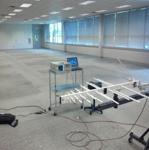
21 Page 21 of 34 Figure 7, Transmitter under test/test Setup
22 Measurement Procedure The measurement bandwidth was set per ANSI/TIA-603C: 2004: Range RBW VBW 30 MHz to 1 GHz 10 khz 300 khz > 1 GHz 1 MHz 3 MHz Page 22 of 34 At each frequency, the antenna was adjusted over a 1 to 2 meter height to maximize the received signal level. Measurements were made on all four sides, using both vertical and horizontal antenna polarizations. Cabinet radiation was measured in the FM-Only mode at 165 watts.
23 Page 23 of Test Results FM Only Horizontal 98MHz F c CP W = 165 Watts FCC R = 10 meters Standard: Spur dbc -RA FL dbuv/m = dbuv/m Tabulated Measurements and results - Worst case Vertical and Horizontal. Antenna factors (AF), and Cable losses (Cable db) were installed in the analyzer so zero was used in these columns below. Front Left Frequency (MHz) Meas dbuv AF db Cable db Spur dbc - RA Frequency (MHz) Meas dbuv AF db Cable db Spur dbc - RA Rear Right Frequency (MHz) Meas dbuv AF db Cable db Spur dbc - RA Frequency (MHz) Meas dbuv AF db Cable db Spur dbc - RA
24 Page 24 of 34 FM Only Vertical 98MHz F c CP W = 165 Watts FCC R = 10 meters Standard: Spur dbc -RA FL dbuv/m = dbuv/m Tabulated Measurements and results - Worst case Vertical and Horizontal. Antenna factors (AF), and Cable losses (Cable db) were installed in the analyzer so zero was used in these columns below. Front Left Frequency (MHz) Meas dbuv AF db Cable db Spur dbc - RA Frequency (MHz) Meas dbuv AF db Cable db Spur dbc - RA Rear Right Frequency (MHz) Meas dbuv AF db Cable db Spur dbc - RA Frequency (MHz) Meas dbuv AF db Cable db Spur dbc - RA
 was used as the signal source.")
25 Page 25 of Substitution Method The substitution method as described in ANSI/TIA-603C: 2004 was used to validate the direct measurements at the highest emission frequencies found. A second broadband antenna was used in place of the transmitter. A signal generator (WQRK SSG-3) was used as the signal source. The substitution results were in fairly close agreement with the direct readings, as indicated in comparing the Sub dbc readings with the Direct dbc.
26 Page 26 of 34 Freq. (MHz.) Pg (dbm) Cable Loss (db) Antenna Gain (dbi) Pd (dbm) TX Watts Sub dbc Direct Limit Antenna orientation Direct result minus substitution result n/a Horizontal Horizontal Horizontal Horizontal Horizontal Horizontal Horizontal Horizontal Horizontal Horizontal Frequency stability Reference 47CFR (a) The frequency stability shall be measured with variation of ambient temperature as follows:.... (3) From 0 deg. to +50 deg. centigrade for equipment to be licensed for use in the Radio Broadcast Services under part 73 of this chapter. (b) Frequency measurements shall be made at the extremes of the specified temperature range and at intervals of not more than 10 deg. centigrade through the range. A period of time sufficient to stabilize all of the components of the oscillator circuit at each temperature level shall be allowed prior to frequency measurement. The short term transient effects on the frequency of the transmitter due to keying (except for broadcast transmitters) and any heating element cycling normally occurring at each ambient temperature level also shall be shown. Only the portion or portions of the transmitter containing the frequency determining and stabilizing circuitry need be subjected to the temperature variation test.
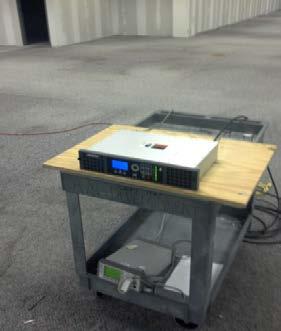
27 Page 27 of 34 (d) The frequency stability shall be measured with variation of primary supply voltage as follows: (1) Vary primary supply voltage from 85 to 115 percent of the nominal value for other than hand carried battery equipment. (3) The supply voltage shall be measured at the input to the cable normally provided with the equipment, or at the power supply terminals if cables are not normally provided. Effects on frequency of transmitter keying (except for broadcast transmitters) and any heating element cycling at the nominal supply voltage and at each extreme also shall be shown Criteria (b) FM stations. (1) The departure of the carrier or center frequency of an FM station with an authorized transmitter output power more than 10 watts may not exceed ±2000 Hz from the assigned frequency Test Setup The transmitter frequency is set by the frequency source in the exciter. To demonstrate compliance, the exciter is placed in a temperature controlled chamber, and powered by an AC variable transformer. It is operated at a range of temperatures, from 0 C to 50 C. Chamber Frequency Counter 30 db Attenuator Exciter Voltmeter Variac Harris Response The transmitter frequency is set by an internal frequency reference. To demonstrate compliance, the transmitter was placed in a temperature controlled chamber, powered by an AC variable transformer. Measurements were taken over the temperature a range of 0 C to 50 C. At each operating temperature the equipment was allowed to stabilize, then operated with the AC variac set to nominal, -15% and +15%, recording the operating frequency at each setting. The following tables list the frequency measurements made and demonstrate the equipment remains within ±2,000 Hz.
28 Page 28 of 34 Test results: Temperature C Hz at 102V (85%) Hz at 120V (100%) Hz at 138V (115%) 0 98,000,016 98,000,017 98,000, ,000,017 98,000,015 98,000, ,000,010 98,000,012 98,000, ,000,008 98,000,010 98,000, ,000,009 98,000,007 98,000, ,000,004 98,000,005 98,000, ,000,003 98,000,002 98,000,005 Equipment Mfr / Model Harris # Calibration Due Date Temperature Chamber Tenney T6C NA Frequency Counter Agilent 53132A /15/13 Variac Staco 3PN1010 NA NA 40 db Attenuator Bird HAR-003 NA NA 6. Frequency spectrum to be investigated Reference(s) 47CFR (a) In all of the measurements set forth in and , the spectrum shall be investigated from the lowest radio frequency signal generated in the equipment, without going below 9 khz, up to at least the frequency shown below: (1) If the equipment operates below 10 GHz: to the tenth harmonic of the highest fundamental frequency or to 40 GHz, whichever is lower. None Criteria Measurement Procedure Conducted spurious measurements are made from 9 khz to the 10 th harmonic. Radiated measurements were made from 30 MHz to the 10 th harmonic Test Results No signals other than harmonics were found.
29 Page 29 of Specifications for Indicating Instruments Reference 47CFR Specifications for indicating instruments. The following requirements and specifications shall apply to indicating instruments used by broadcast stations: (a) Linear scale instruments: (1) Length of scale shall not be less than 2.3 inches (5.8 cm). (2) Accuracy shall be at least 2 percent of the full scale reading. (3) The maximum rating of the meter shall be such that it does not read off scale during modulation or normal operation. (4) Scale shall have at least 40 divisions. (5) Full scale reading shall not be greater than five times the minimum normal indication Results Not applicable. No analog metering used on the FAX150. (b) Instruments having square-lawscales: (1) Meet the requirements of paragraphs(a) (1), (2), and (3) of this section for linear scale instruments. (2) Full scale reading shall not be greater than three times the minimum normal indication. (3) No scale division above one-third full scale reading shall be greater than one-thirtieth of the full scale reading. (Example: An ammeter meeting requirement (1) having full scale reading of 6 amperes is acceptable for reading currents from 2 to 6 amperes, provided no scale division between 2 and 6 amperes is greater than one-thirtieth of 6 amperes, 0.2 ampere.) 7.2. Results Not applicable. (c) Instruments having logarithmic scales: (1) Meet the requirements of paragraphs (a) (1), (2), and (3) of this section for linear scale instruments. (2) Full scale reading shall not be greater than five times the minimum normal indication. (3) No scale division above one-fifth full scale reading (in watts) shall be greater than one-thirtieth of the full scale reading. Example: A wattmeter meeting requirement (3) having full scale reading of 1,500 watts is acceptable for reading power from 300 to 1,500 watts, provided no scale division between 300 and 1,500 watts is greater than one-thirtieth of 1,500 watts or 50 watts.) 7.3. Results Not applicable. (d) Instruments having expanded scales:
30 Page 30 of 34 (1) Shall meet the requirements of paragraphs (a) (1), (2), and (3) of this section for linear scale instruments. (2) Full scale reading shall not be greater than five times the minimum normal indication. (3) No scale division above one-fifth full scale reading shall be greater than one-fiftieth of the full scale reading. (Example: An ammeter meeting the requirement (1) is acceptable for indicating current from 1 to 5 amperes, provided no division between 1 and 5 amperes is greater than onefiftieth of 5 amperes, 0.1 ampere.) 7.4. Results The FAX150 complies with this requirement. (e) Digital meters, printers, or other numerical readout devices may be used in addition to or in lieu of indicating instruments meeting the specifications of paragraphs (a), (b), (c), and (d) of this section. The readout of the device must include at least three digits and must indicate the value of the parameter being read to an accuracy of 2%. The multiplier, if any, to be applied to the reading of each parameter must be indicated at the operating position Results The exciters meet this requirement. It is otherwise not applicable. (f) No instrument which has been broken or appears to be damaged or defective, or the accuracy of which is questionable shall be used, until it has been checked, and if necessary repaired and recalibrated by the manufacturer or qualified instrument repair service. Repaired instruments shall not be used unless a certificate of calibration has been provided showing that the instrument conforms to the manufacturer s specifications for accuracy. 8. Description of Modifications Performed to Achieve Compliance None.

31 9. Detailed Photos of EUT Page 31 of 34 Figure 8, Front

32 Page 32 of 34 Figure 9, Rear
33 Page 33 of 34 Figure 10, Left

34 Page 34 of 34 Figure11, Right
Measurement Procedure & Test Equipment Used
 Measurement Procedure & Test Equipment Used Except where otherwise stated, all measurements are made following the Electronic Industries Association (EIA) Minimum Standard for Portable/Personal Land Mobile
FCC ID: A3LSLS-BD106Q. Report No.: HCT-RF-1801-FC003. Plot Data for Output Port 2_QPSK 9 khz ~ 150 khz Middle channel 150 khz ~ 30 MHz Low channel
 Plot Data for Output Port 2_QPSK 9 khz ~ 150 khz Middle channel 150 khz ~ 30 MHz Low channel 30 MHz ~ 1 GHz Middle channel 1 GHz ~ 2.491 GHz Low channel 2.695 GHz ~ 12.75 GHz High channel 12.75 GHz ~ 26.5
Test Report. Prepared for: Becker Avionics, Inc. Model: TG Description: Aeronautical basestation radio used for emergencies
 Test Report Prepared for: Becker Avionics, Inc Model: TG660-50 Description: Aeronautical basestation radio used for emergencies Serial Number: 10001, 10002 FCC ID: 2AHX9TG660 To FCC Part 87 Date of Issue:
FCC PART 90 AND IC RSS-119, RSS-GEN TEST REPORT
 849 NW STATE ROAD 45 NEWBERRY, FL 32669 USA PH: 888.472.2424 OR 352.472.5500 FAX: 352.472.2030 EMAIL: INFO@TIMCOENGR.COM HTTP://WWW.TIMCOENGR.COM FCC PART 90 AND IC RSS-119, RSS-GEN TEST REPORT APPLICANT
FCC Part 90 Certification Application. FCC Form 731. For The. Guardian UHF RADIO MODEM FCC ID: NP
 Page 1 of 41 CAlamp Wireless Networks Corp. 299 Johnson Avenue, Suite 110 Waseca, MN 56093-0833 USA Phone: 507-833-8819 Fax: 507-833-6748 FCC Part 90 Certification Application FCC Form 731 For The Guardian
FCC PART 80 & 90 TEST REPORT
 849 NW STATE ROAD 45 NEWBERRY, FL 32669 USA PH: 888.472.2424 OR 352.472.5500 FAX: 352.472.2030 EMAIL: INFO@TIMCOENGR.COM HTTP://WWW.TIMCOENGR.COM FCC PART 80 & 90 TEST REPORT APPLICANT FCC ID MODEL NUMBER
[Uplink_High] 150 ~ 30
![[Uplink_High] 150 ~ 30](/thumbs/93/117947833.jpg "[Uplink_High] 150 ~ 30") Report No.: HCT-R-1611-F007-2 Model: GST-IC-ELITE-1943 Page 97 of 125 9 ~ 150 [Uplink_High] 150 ~ 30 30 ~ 1 1 ~ 1.845 97 / 125 Report No.: HCT-R-1611-F007-2 Model: GST-IC-ELITE-1943 Page 98 of 125 1.845
Report No.: HCT-R-1611-F007-2 Model: GST-IC-ELITE-1943 Page 97 of 125 9 ~ 150 [Uplink_High] 150 ~ 30 30 ~ 1 1 ~ 1.845 97 / 125 Report No.: HCT-R-1611-F007-2 Model: GST-IC-ELITE-1943 Page 98 of 125 1.845
TIMCO ENGINEERING INC.
 Test Report Product Name: FM EXCITER - TRANSMITTER Applicant: NiCOM USA, INC. 2626 SOUTHPORT WAY SUITE B NATIONAL CITY, CA 91950 Date Receipt: DECEMBER 29, 2003 Date Tested: JANUARY 13, 2004 COVER SHEET
MEASUREMENT PROCEDURE AND TEST EQUIPMENT USED
 MEASUREMENT PROCEDURE AND TEST EQUIPMENT USED Except where otherwise stated, all measurements are made following the Electronic Industries Association (EIA) Minimum Standard for Portable/Personal Land
FCC PART 95 MEASUREMENT AND TEST REPORT. Powerwerx, Inc.
 FCC PART 95 MEASUREMENT AND TEST REPORT For Powerwerx, Inc. 23695 Via Del Rio Yorba Linda California 92887, United States FCC ID: 2ACK8TR505D Report Type: Original Report Product Type: Two-way radio Test
REPORT ON Radio testing of the VERTEX STANDARD VX-2100-G6-45 / VX-2200-G6-45 In accordance with ANSI/TIA/EIA-603, RSS-119. Report number TA000506
 Page 1 of 48 REPORT ON Radio testing of the VERTEX STANDARD VX-2100-G6-45 / VX-2200-G6-45 In accordance with ANSI/TIA/EIA-603, RSS-119 Report number TA000506 June 2007 Report number TA000506 Page 2 of
Vertex Standard Co., Ltd. Page 1 of 38
 Page 1 of 38 REPORT ON Radio testing of the VERTEX STANDARD VX-2100-G6-45 / VX-2200-G6-45 In accordance with ANSI/TIA/EIA-603-C, RSS-119 Report number TA001110 December 2011 Report number TA001110 Page
Page 1 of 51 Report No.: T TEST REPORT FCC ID: 2AGJ5WAP-30. In Accordance with: FCC PART 15, SUBPART C : 2015 (Section 15.
 Page 1 of 51 Report No.: T1851663 01 TEST REPORT FCC ID: 2AGJ5WAP-30 Applicant Address : Gonsin Conference Equipment Co., Ltd : No.401-406,Block C, Idea Industry Park, No.41 Fengxiang Road, Shunde, Foshan,
ROGERS LABS, INC. TEST REPORT For APPLICATION of CERTIFICATION. For
 ROGERS LABS, INC. 4405 West 259 th Terrace Louisburg, KS 66053 Phone / Fax (913) 837-3214 TEST REPORT For APPLICATION of CERTIFICATION For GARMIN INTERNATIONAL, INC. 1200 East 151st Street Olathe, KS 66062
TEST REPORT Part 95(A/B) & IC RSS-210(Issue 8)
 & IC RSS-210(Issue 8)") TEST REPORT Part 95(A/B) & IC RSS-210(Issue 8) Equipment Under Test FRS / GMRS Model Name LXT600 FCC ID MMALXT600 IC Certification 3690A- LXT600 Applicant Midland Radio Corporation Manufacturer Global
TEST REPORT Part 95(A/B) & IC RSS-210(Issue 8) Equipment Under Test FRS / GMRS Model Name LXT600 FCC ID MMALXT600 IC Certification 3690A- LXT600 Applicant Midland Radio Corporation Manufacturer Global
MODEL: P5400 UHF-L Portable Radio
 Engineering and Testing for EMC and Safety Compliance Accredited under NVLAP Lab Code 200061-0 Certification Report M/A-COM, Inc. 221 Jefferson Ridge Parkway Lynchburg, VA 24501 Daryl Popowitch Phone:
FCC 47 CFR PART 15 SUBPART C INDUSTRY CANADA RSS-210 ISSUE 8 BLUETOOTH LOW ENERGY CERTIFICATION TEST REPORT FOR. 2.4GHz LE MODULE MODEL NUMBER: RN4020
 FCC 47 CFR PART 15 SUBPART C INDUSTRY CANADA RSS-210 ISSUE 8 BLUETOOTH LOW ENERGY CERTIFICATION TEST REPORT FOR 2.4GHz LE MODULE MODEL NUMBER: RN4020 REPORT NUMBER: 14U17191-1 ISSUE DATE: MARCH 21, 2014
FCC PART & IC RSS GHz FHSS TEST REPORT
 FCC PART 15.247 & IC RSS-247 2.4 GHz FHSS TEST REPORT 849 NW State Road 45 Newberry, FL 32669 USA Ph.: 888.472.2424 or 352.472.5500 Fax: 352.472.2030 Email: info@timcoengr.com Website: www.timcoengr.com
FCC Test Report. Report No.: AGC FE02 CLIENT : INNOVATIVE CONCEPTS AND DESIGN LLC. Attestation of Global Compliance (Shenzhen) Co., Ltd.
 Co., Ltd.") Page 1 of 43 FCC Test Report Report No.: AGC03588150607FE02 FCC ID : 2AE6GUHF 6000HHM APPLICATION PURPOSE : ORIGINAL EQUIPMENT PRODUCT DESIGNATION : Wireless Microphone BRAND NAME : Gemini MODEL NAME :
Page 1 of 43 FCC Test Report Report No.: AGC03588150607FE02 FCC ID : 2AE6GUHF 6000HHM APPLICATION PURPOSE : ORIGINAL EQUIPMENT PRODUCT DESIGNATION : Wireless Microphone BRAND NAME : Gemini MODEL NAME :
FCC REPORT. Dongguan Hele Electronics Co.,Ltd. * In the configuration tested, the EUT complied with the standards specified above.
 Report No.: GTS201708000040F02 FCC REPORT Applicant: Address of Applicant: Manufacturer: Dongguan Hele Electronics Co.,Ltd. Dalingya Industrial Zone,Daojiao Town,Dongguan City,Guangdong,China Dongguan
UNIDEN AMERICA CORPORATION 4700 AMON CARTER BLVD. FORT WORTH TEXAS UNITED STATES
 849 NW STATE ROAD 45 NEWBERRY, FL 32669 USA PH: 888.472.2424 OR 352.472.5500 FAX: 352.472.2030 EMAIL: INFO@TIMCOENGR.COM HTTP://WWW.TIMCOENGR.COM TEST REPORT PER FCC Part 15, Subparts B, C, and D IC RSS-213
FCC REPORT. 570 E1 Camino Real #200, Redwood City, CA 94063, United Manufacturer:
 FCC REPORT Applicant: Address of Applicant: Manufacturer: Striiv Inc. 570 E1 Camino Real #200, Redwood City, CA 94063, United States Striiv Inc. Address of 570 E1 Camino Real #200, Redwood City, CA 94063,
7. Transmitter Radiated Spurious Emissions and Conducted Spurious Emission
 7. Transmitter Radiated Spurious Emissions and Conducted Spurious Emission 7.1 Test Setup Refer to the APPENDIX I. 7.2 Limit According to 15.247(d), in any 100 khz bandwidth outside the frequency band
FCC CFR47 PART 15 SUBPART C INDUSTRY CANADA RSS-GEN AND RSS-210 CERTIFICATION TEST REPORT FOR BROADCOM BLUETOOTH MODULE MODEL NUMBER: BCM92046MD
 FCC CFR47 PART 15 SUBPART C INDUSTRY CANADA RSS-GEN AND RSS-210 CERTIFICATION TEST REPORT FOR BROADCOM BLUETOOTH MODULE MODEL NUMBER: BCM92046MD IC #: 4324A-BRCM1029 REPORT NUMBER: 07U11199-1C ISSUE DATE:
EXHIBIT 10 TEST REPORT. FCC Parts 2 & 24
 EXHIBIT 10 TEST REPORT FCC Parts 2 & 24 SUB-EXHIBIT 10.1 MEASUREMENT PER SECTION 2.1033 (C) (14) OF THE RULES SECTION 2.1033 (c) (14) The data required by Section 2.1046 through 2.1057, inclusive, measured
TEST REPORT FCC ID: 2ADMF-HC06. : bluetooth module keyes HC-06, keyes hc-05, FUNDUINO HC-06, FUNDUINO hc-05
 Shenzhen Certification Technology Service Co., Ltd. 2F, Building B, East Area of Nanchang Second Industrial Zone, Gushu 2 nd Road, Bao'an District, Shenzhen 518126, P.R. China TEST REPORT FCC ID: 2ADMF-HC06
FCC REPORT. Dongguan Hele Electronics Co.,Ltd. * In the configuration tested, the EUT complied with the standards specified above.
 + Applicant: Address of Applicant: Manufacturer: FCC REPORT Dongguan Hele Electronics Co.,Ltd. Report No.: GTS201708000040F01 Dalingya Industrial Zone,Daojiao Town,Dongguan City,Guangdong,China Dongguan
FCC Part 90 Mobile UHF Repeater Test Report
 849 NW STATE ROAD 45 NEWBERRY, FL 32669 USA PH: 888.472.2424 OR 352.472.5500 EMAIL: INFO@TIMCOENGR.COM HTTP://WWW.TIMCOENGR.COM FCC Part 90 Mobile UHF Repeater Test Report APPLICANT FCC ID MODEL NUMBER
FCC CFR47 PART 15 SUBPART C INDUSTRY CANADA RSS-247 ISSUE 1 BLUETOOTH LOW ENERGY CERTIFICATION TEST REPORT FOR
 FCC CFR47 PART 15 SUBPART C INDUSTRY CANADA RSS-247 ISSUE 1 BLUETOOTH LOW ENERGY CERTIFICATION TEST REPORT FOR WLAN 2X2 MIMO 802.11a/b/g/n/ac with BLUETOOTH MODEL NUMBER: P2180 REPORT NUMBER: 15U21878-E2V1
Revision history. Revision Date of issue Test report No. Description KES-RF-14T0042 Initial
 Page (2 ) of (34) Revision history Revision Date of issue Test report No. Description - 2014.08.25 Initial Page (3 ) of (34) TABLE OF CONTENTS 1. General information... 4 1.1. EUT description... 4 1.2.
Spectrian Dual Mode Cellular Power Amplifier Model No.: SCLPA 800 CR FCC ID: I2ONTHX51AA
 A Class II Permissive Change - FCC Part 22 Type Acceptance Test Report for Spectrian Dual Mode Cellular Power Amplifier Model No.: SCLPA 800 CR FCC ID: I2ONTHX51AA Date of Report: May 26, 1999 Total No.
FCC 47 CFR PART 15 SUBPART C CERTIFICATION TEST REPORT FOR. Bluetooth Remote Control for Video Set Top Box MODEL NUMBER: IPRC1000 FCC ID: 2ABTE-L3YJC9
 FCC 47 CFR PART 15 SUBPART C CERTIFICATION TEST REPORT FOR Bluetooth Remote Control for Video Set Top Box MODEL NUMBER: IPRC1000 REPORT NUMBER: 15U22448-E1V4 ISSUE DATE: 3/7/2016 Prepared for Verizon Online
TRANSMITTER MODEL: KAS-2030M
 Page 1 of 16 FCC PART 15, SUBPART B and C TEST REPORT for TRANSMITTER MODEL: KAS-2030M Prepared for WILDLIFE TECHNOLOGIES 115 WOLCOTT STREET MANCHESTER, NEW HAMPSHIRE 03103 Prepared by: KYLE FUJIMOTO Approved
FCC ID: B4OCC264BPA-S
 FCC TEST REPORT FCC ID: B4OCC264BPA-S Product : Bluetooth LE Module Model Name : CC264BPA-S, CC265BPA-S, CC26xBPA Brand : GT-tronics Report No. : PTC801181160622E-FC01 Prepared for GT-tronics HK Ltd Unit
Federal Communications Commission Office of Engineering and Technology Laboratory Division
 Federal Communications Commission Office of Engineering and Technology Laboratory Division June 4, 2013 Measurement Guidance for Certification of Licensed Digital Transmitters 1.0 Introduction and Applicability
8370 Court Avenue, Suite B-1 Ellicott City, Maryland (410) FCC CERTIFICATION
 FCC CERTIFICATION") IKUSI FCC INFORMATION RF Measurement Report Prepared by:: National Certification Laboratory 8370 Court Avenue, Suite B-1 Ellicott City, Maryland 21043 (410) 461-5548 IIn Supportt off:: FCC CERTIFICATION
IKUSI FCC INFORMATION RF Measurement Report Prepared by:: National Certification Laboratory 8370 Court Avenue, Suite B-1 Ellicott City, Maryland 21043 (410) 461-5548 IIn Supportt off:: FCC CERTIFICATION
OUTDOOR SOUND MODULE/TRANSMITTER MODEL: THE BANDIT
 Page 1 of 16 FCC PART 15, SUBPART B and C TEST REPORT for OUTDOOR SOUND MODULE/TRANSMITTER MODEL: THE BANDIT Prepared for MINASKA OUTDOORS 6517 PLATTE AVENUE LINCOLN, NEBRASKA 68507 Prepared by: KYLE FUJIMOTO
Version TEST REPORT NO. DATE DESCRIPTION. HCTR1208FR49 August 29, 2012 First Approval Report
 Version TEST REPORT NO. DATE DESCRIPTION HCTR1208FR49 August 29, 2012 First Approval Report Revise information for frequency range on page 8 Page 2 of 39 Table of Contents 1. GENERAL INFORMATION... 4 2.
Version TEST REPORT NO. DATE DESCRIPTION. HCTR1208FR50 August 29, 2012 First Approval Report
 Version TEST REPORT NO. DATE DESCRIPTION First Approval Report Page 2 of 101 Table of Contents 1. GENERAL INFORMATION... 4 2. INTRODUCTION... 5 2.1. EUT DESCRIPTION... 5 2.2. MEASURING INSTRUMENT CALIBRATION...
EXHIBIT 7: MEASUREMENT PROCEDURES Pursuant 47 CFR 2.947
 EXHIBIT 7: MEASUREMENT PROCEDURES Pursuant 47 CFR 2.947 7.1 RF Power -- Pursuant to 47 CFR 2.947(c) Method of Conducted Output Power Measurement: Adaptation of TIA/EIA-603-A clause 2.2.1 for Pulsed Measurements
FCC 47 CFR PART 15 SUBPART C CERTIFICATION TEST REPORT FOR. RF ID Reader MODEL NUMBER: A-405 FCC ID: WFQITCS-A-405 IC: 10717A-ITCSA405
 FCC 47 CFR PART 15 SUBPART C CERTIFICATION TEST REPORT FOR RF ID Reader MODEL NUMBER: A-405 REPORT NUMBER: 10906664A ISSUE DATE: December 12, 2015 Prepared for RF Controls LLC 1400 S 3 RD Street Suite
Table of Contents 1. GENERAL INFORMATION SYSTEM TEST CONFIGURATION CONDUCTED EMISSIONS TEST RADIATED EMISSION TEST...
 Table of Contents 1. GENERAL INFORMATION... 4 1.1 PRODUCT DESCRIPTION FOR EQUIPMENT UNDER TEST... 4 1.2 RELATED SUBMITTAL(S) / GRANT (S)... 7 1.3 TEST METHODOLOGY... 7 1.4 EQUIPMENT MODIFICATIONS... 7
AN4949 Application note
 Application note Using the S2-LP transceiver under FCC title 47 part 15 in the 902 928 MHz band Introduction The S2-LP is a very low power RF transceiver, intended for RF wireless applications in the sub-1
A Test Lab Techno Corp. Report Number:1410FR27
 Mode 5: IEEE 802.11n 2.4GHz 40MHz Link Mode 2422 2437 2452 Page 41 of 85 9 Out of Band Conducted Emissions Measurement 9.1. Limit In any 100 khz bandwidth outside the frequency band in which the spread
FCC REPORT. Dongguan Hele Electronics Co., Ltd. J11, J12, J13, Q7, Q28, Q26, Q29
 FCC REPORT Applicant: Dongguan Hele Electronics Co., Ltd. Address of Applicant: Dalingya Industrial Zone, Daojiao Town, Dongguan City, Guangdong China Equipment Under Test (EUT) Product Name: Model No.:
FCC CFR47 PART 15 SUBPART C CERTIFICATION TEST REPORT FOR PCMCIA RFID READER CARD MODEL NUMBER: MPR6000 FCC ID: NTTWJMPR6XXX REPORT NUMBER: 04U2954-3
 FCC CFR47 PART 15 SUBPART C CERTIFICATION TEST REPORT FOR PCMCIA RFID READER CARD MODEL NUMBER: MPR6000 FCC ID: NTTWJMPR6XXX REPORT NUMBER: 04U2954-3 ISSUE DATE: NOVEMBER 22, 2004 Prepared for WJ COMUNICATIONS
Title: Test on 5.8 GHz Band Outdoor WiFi (802.11b/g) Wireless Base Station
 Wireless Base Station") Page 20 of 51 Pages 7.5. Conducted spurious emission 7.5.1. Requirements: Clause 15.247(d). In any 100 khz bandwidth outside the frequency band in which the spread spectrum or digitally modulated intentional
Page 20 of 51 Pages 7.5. Conducted spurious emission 7.5.1. Requirements: Clause 15.247(d). In any 100 khz bandwidth outside the frequency band in which the spread spectrum or digitally modulated intentional
STUDIO TO TRANSMITTER LINKING SYSTEM
 RFS37 May 1995 (Issue 1) SPECIFICATION FOR RADIO LINKING SYSTEM: STUDIO TO TRANSMITTER LINKING SYSTEM USING ANGLE MODULATION WITH CARRIER FREQUENCY SEPARATION BETWEEN 75 AND 500 khz Communications Division
Occupied Bandwidth Measurements (FCC Rule ) KGHP, Gig Harbor, Washington. September 26, 2012
 KGHP, Gig Harbor, Washington. September 26, 2012") Occupied Bandwidth Measurements (FCC Rule 73.317) KGHP, Gig Harbor, Washington September 26, 2012 On September 26 th, 2012, Boyd Broadcast Technical Services made measurements of KGHP, Gig Harbor, Washington,
Occupied Bandwidth Measurements (FCC Rule 73.317) KGHP, Gig Harbor, Washington September 26, 2012 On September 26 th, 2012, Boyd Broadcast Technical Services made measurements of KGHP, Gig Harbor, Washington,
FCC 47 CFR PART 15 SUBPART C INDUSTRY CANADA RSS-210 ISSUE 8 CERTIFICATION TEST REPORT FOR. Dolphin CT50
 FCC 47 CFR PART 15 SUBPART C INDUSTRY CANADA RSS-210 ISSUE 8 CERTIFICATION TEST REPORT FOR Dolphin CT50 MODEL NUMBER: CT50LFN IC ID: 1693B-CT50LFN REPORT NUMBER: 15U20259-E6 ISSUE DATE: JUNE 08, 2015 Prepared
TEST REPORT NO. DATE DESCRIPTION
 Version TEST REPORT NO. DATE DESCRIPTION HCT-R-1608-F020 August 19, 2016 - First Approval Report 2 / 50 Table of Contents 1. GENERAL INFORMATION... 4 2. INTRODUCTION... 5 2.1. EUT DESCRIPTION... 5 2.2.
TABLE OF CONTENTS APPLICANT: FLYING DRAGON DEVELOPMENT LTD. FCC ID: PNX-FD383-SV-01 TEST REPORT CONTAINING:
 TABLE OF CONTENTS APPLICANT: FLYING DRAGON DEVELOPMENT LTD. FCC ID: PNX-FD383-SV-01 TEST REPORT CONTAINING: PAGE 1...TEST EQUIPMENT LIST & TEST PROCEDURE PAGE 2...TEST PROCEDURE CONTD. PAGE 3...RADIATION
FCC PART 15C TEST REPORT FOR CERTIFICATION On Behalf of. ION Audio, LLC. Portable Karaoke PA speaker with vocal effects
 FCC PART 15C TEST REPORT FOR CERTIFICATION Behalf of ION Audio, LLC Portable Karaoke PA speaker with vocal effects Model Number: ipk3 KARAOKE STAR PLUS FCC ID: 2AB3E-IPK3 Prepared for: Prepared By: ION
FCC PART 80 RADAR TEST REPORT
 849 NW STATE ROAD 45 NEWBERRY, FL 32669 USA PH: 888.472.2424 OR 352.472.5500 FAX: 352.472.2030 EMAIL: INFO@TIMCOENGR.COM HTTP://WWW.TIMCOENGR.COM FCC PART 80 RADAR TEST REPORT APPLICANT ALPHATRON MARINE
Radiated Spurious Emission Testing. Jari Vikstedt
 Radiated Spurious Emission Testing Jari Vikstedt jari.vikstedt@ets-lindgren.com What is RSE? RSE = radiated spurious emission Radiated chamber Emission EMI Spurious intentional radiator 2 Spurious Spurious,
FCC Part 90 Rules Test Report
 Page 1 of 147 FCC Part 90 Rules Test Report FCC ID : POD-DMR2 PRODUCT DESIGNATION : DMR Digital Transceiver BRAND NAME : TYT MODEL NAME : MD-2017, MD-760 CLIENT : TYT ELECTRONICS CO., LTD DATE OF ISSUE
Test Report. Prepared for: Technologic Systems, Inc. Model: TS Description: Embedded Computer Board. Serial Number: N/A. FCC Part 15B Class A
 Test Report Prepared for: Technologic Systems, Inc. Model: TS-7990 Description: Embedded Computer Board Serial Number: N/A To FCC Part 15B Class A And IC ICES-003 Issue 6 (January 2016) Date of Issue:
Channel 01 (2422MHz)
") Product : PC to TV Transmitter [u17] Test Item : RF Antenna Conducted Spurious Test Site : No.3 OATS Test Mode : Mode 4: Transmit (802.11n MCS0 15Mbps 40M-BW) Channel 01 (2422MHz) Page: 57 of 109 Page:
Product : PC to TV Transmitter [u17] Test Item : RF Antenna Conducted Spurious Test Site : No.3 OATS Test Mode : Mode 4: Transmit (802.11n MCS0 15Mbps 40M-BW) Channel 01 (2422MHz) Page: 57 of 109 Page:
FCC PART 15C TEST REPORT FOR CERTIFICATION On Behalf of. DEI Sales Inc. dba Definitive Technology. Model Number: STUDIO SLIM SUBWOOFER
 FCC PART 15C TEST REPORT FOR CERTIFICATION On Behalf of DEI Sales Inc. dba Definitive Technology 3.1 Home Theater Sound Bar and Wireless Subwoofer System Model Number: STUDIO SLIM SUBWOOFER FCC ID: IPUSTUSLIMSUB
AN5029 Application note
 Application note Using the S2-LP transceiver with FEM at 500 mw under FCC title 47 part 15 in the 902 928 MHz band Introduction The S2-LP very low power RF transceiver is intended for RF wireless applications
Land and Coast Station Transmitters Operating in the Band khz
 Issue 3 January 2016 Spectrum Management Radio Standards Specification Land and Coast Station Transmitters Operating in the Band 200-535 khz Aussi disponible en français CNR-117 Preface Radio Standards
Ave output power ANT 1(dBm) Ave output power ANT 2 (dbm)
 Ave output power ANT 2 (dbm)") Page 41 of 103 9.6. Test Result The test was performed with 802.11b Channel Frequency (MHz) power ANT 1(dBm) power ANT 2 (dbm) power ANT 1(mW) power ANT 2 (mw) Limits dbm / W Low 2412 7.20 7.37 5.248 5.458
Page 41 of 103 9.6. Test Result The test was performed with 802.11b Channel Frequency (MHz) power ANT 1(dBm) power ANT 2 (dbm) power ANT 1(mW) power ANT 2 (mw) Limits dbm / W Low 2412 7.20 7.37 5.248 5.458
Class II Permissive Change Report
 Engineering and Testing for EMC and Safety Compliance Class II Permissive Change Report Harris Corporation 221 Jefferson Ridge Parkway Lynchburg, VA 24501 Daryl Popowitch Phone: (434) 455-9527 Model: P5400
TEST REPORT. For RFID READER/WRITER. In conformity with. FCC CFR 47 Part15 Subpart C
 TEST REPORT For RFID READER/WRITER In conformity with FCC CFR 47 Part15 Subpart C Model: TR3XM-SD01 / TR3XM-SU01 / TR3XM-SN01 FCC ID: MK4TR3XM-SX01 Test Item: RFID READER/WRITER Report No: RY1203Z12R1
TEST REPORT MOBILE MICROWAVE VIDEO TRANMITTER FCC ID: FC3HDX2025D MODEL: HDX-1100S. APPLICANT: VISLINK, Inc. May 7, 2013 PAGE 1 OF 33
 TEST REPORT MOBILE MICROWAVE VIDEO TRANMITTER FCC ID: FC3HDX2025D MODEL: HDX-1100S APPLICANT: VISLINK, Inc. May 7, 2013 PAGE 1 OF 33 TABLE OF CONTENTS Section 1 INTRODUCTION 3 APPLICATION 4 TECHNICAL DATA
REPORT REVISION HISTORY...
 Reference No.: WTS17S0579239E Page 2 of 39 2 Contents Page 1 COVER PAGE... 1 2 CONTENTS... 2 3 REPORT REVISION HISTORY... 3 4 GENERAL INFORMATION... 4 4.1 GENERAL DESCRIPTION OF E.U.T.... 4 4.2 DETAILS
Measurement of RF Emissions from a Caterpillar Inc. MSS3s RF ID Key Fob
 Measurement of RF Emissions from a Caterpillar Inc. MSS3s RF ID Key Fob For Caterpillar Inc. 330 S.W. Adams Street Peoria, IL 61630 P.O. Number JBL 11260 Date Tested May 11, 2016 Test Personnel Mark Longinotti
FCC CFR47 PART 15 SUBPART C INDUSTRY CANADA RSS-210 ISSUE 7 CERTIFICATION TEST REPORT FOR g WIRELESS LAN + BLUETOOTH PCI-E MINI CARD
 FCC CFR47 PART 15 SUBPART C INDUSTRY CANADA RSS-210 ISSUE 7 CERTIFICATION TEST REPORT FOR 802.11g WIRELESS LAN + BLUETOOTH PCI-E MINI CARD MODEL NUMBER: BCM94312HMGB REPORT NUMBER: 09U12439-2 ISSUE DATE:
L.S. Compliance, Inc. W66 N220 Commerce Court Cedarburg, WI
 L.S. Compliance, Inc. W66 N220 Commerce Court Cedarburg, WI 53012 262-375-4400 COMPLIANCE TESTING OF: Quartex Synchronization Transmitter Model FM-72 PREPARED FOR: Quartex, Division of Primex, Inc. 965
ACCORDING TO: FCC part 15 subpart C, and subpart B FOR:
 Electrical Hermon Laboratories Ltd. P.O.Box 23, Binyamina 30500, Israel Tel. +972 4628 8001 Fax. +972 4628 8277 E-mail: mail@hermonlabs.com TEST REPORT ACCORDING TO: FCC part 15 subpart C, 15.247 and subpart
Federal Communications Commission Office of Engineering and Technology Laboratory Division
 April 9, 2013 Federal Communications Commission Office of Engineering and Technology Laboratory Division Guidance for Performing Compliance Measurements on Digital Transmission Systems (DTS) Operating
FCC REPORT. Lightcomm Technology Co., Ltd.
 FCC REPORT Report No.: GTS201608000267E01 Applicant: Lightcomm Technology Co., Ltd. Address of Applicant: RM 1808 18/F FO TAN INDUSTRIAL CENTRE NOS. 26-28 AU PUI WAN STREET FO TAN SHATIN NEW TERRITORIES
APPLICATION For FCC And INDUSTRY CANADA GRANT OF CERTIFICATION
 APPLICATION For FCC And INDUSTRY CANADA GRANT OF CERTIFICATION FOR Models: 011-01487-00 and 011-001487-02 Marine Radar Equipment GPN s 011-01487-00 and 011-001487-02 FOR GARMIN INTERNATIONAL, INC. 1200
FCC & IC Class II Permissive Change Report
 Engineering Solutions & Electromagnetic Compatibility Services FCC & IC Class II Permissive Change Report Standards Referenced for this Report Part 2: 2010 Frequency Allocations and Radio Treaty Matters;
Version TEST REPORT NO. DATE DESCRIPTION
 Version NO. DATE DESCRIPTION HCTR1302FR13 February 14, 2013 - First Approval Report - Additional Model Name Page 2 of 25 Table of Contents 1. GENERAL INFORMATION... 4 2. EUT DESCRIPTION... 4 3. TEST METHODOLOGY...
TABLE OF CONTENTS 1. GENERAL INFORMATION... 4
 TABLE OF CONTENTS 1. GENERAL INFORMATION... 4 1.1. EUT DESCRIPTION... 4 1.2. TEST STANDARDS AND RESULTS... 5 1.3. FACILITIES AND ACCREDITATIONS... 6 1.3.1. FACILITIES... 6 1.3.2. TEST ENVIRONMENT CONDITIONS...
This report contains the test setups and data required by the FCC for equipment authorization in accordance with Title 47 parts 2, and 87.
 FCC test report for the ADR-7050 Radio This report contains the test setups and data required by the FCC for equipment authorization in accordance with Title 47 parts 2, and 87. Prior to this FCC approval
Description of Test Facility
 Description of Test Facility Name: Address: Intertek Testing Services Limited Shanghai Building No.86, 1198 Qinzhou Road(North), Shanghai 200233, P.R. China FCC Registration Number: 236597 IC Assigned
FCC Part 22H & 24E Measurement and Test Report
 FCC Part 22H & 24E Measurement and Test Report For Shenzhen Concox Information Technology Co., Ltd Floor 4th, Building B, Gaoxinqi Industrial Park, Liuxian 1st Road, District 67, Bao an, Shenzhen, China
TEST REPORT Part 90 & IC RSS-119(Issue 11)
") TEST REPORT Part 90 & IC RSS-119(Issue 11) Equipment under test ALPHA & SERIAL TX Model name LTK-1400AHN FCC ID QBT LTK-1400AHN IC 5269A- LTK1400AHN Applicant Lee Technology Korea Co., Ltd. Manufacturer
TEST REPORT Part 90 & IC RSS-119(Issue 11) Equipment under test ALPHA & SERIAL TX Model name LTK-1400AHN FCC ID QBT LTK-1400AHN IC 5269A- LTK1400AHN Applicant Lee Technology Korea Co., Ltd. Manufacturer
Test Report Version. Test Report No. Date Description. DRTFCC Sep. 12, 2014 Initial issue
 DEMC1407-02828 FCC ID: 2AAAQH660W Test Report Version Test Report No. Date Description DRTFCC1409-1165 Sep. 12, 2014 Initial issue Page 2 DEMC1407-02828 FCC ID: 2AAAQH660W Table of Contents 1. EUT DESCRIPTION...
APPLICATION FOR CERTIFICATION On Behalf of Futaba Corporation Radio Control Model No.:T10CG-2.4G FCC ID:AZPT10CG-24G Brand : Futaba
 FCC ID. AZPT10CG-24G Page 1 of 56 APPLICATION FOR CERTIFICATION On Behalf of Futaba Corporation Radio Control Model No.:T10CG-2.4G FCC ID:AZPT10CG-24G Brand : Futaba Prepared for : Futaba Corporation 1080
FCC Part 90 Rules Test Report
 Page 1 of 147 FCC Part 90 Rules Test Report FCC ID : POD-DMR2 PRODUCT DESIGNATION : DMR Digital Transceiver BRAND NAME : TYT MODEL NAME : MD-2017, MD-760 CLIENT : TYT ELECTRONICS CO., LTD DATE OF ISSUE
FCC Test Report - UMTS Band 4
 FCC Test Report - UMTS Band 4 Report ID: 03360-RF-00099 FCC ID : AZ489FT7078 Tested Model : LEX L10i Test Date : Jan 13, 2016 ~ Feb 20, 2016 Issued Date : 26 Feb, 2016 Applicant : Motorola Solution Malaysia
Report No.: HCT-R-1507-F015-2 Model: SW100 Page 2 of 52. Version TEST REPORT NO. DATE DESCRIPTION
 Report No.: HCT-R-1507-F015-2 Model: SW100 Page 2 of 52 Version TEST REPORT NO. DATE DESCRIPTION HCT-R-1507-F015 July 10, 2015 - First Approval Report HCT-R-1507-F015-1 July 20,2015 - Updated the KDB version.
SHURE ELECTROMAGNETIC COMPATIBILITY LABORATORY TEST REPORT
 SHURE ELECTROMAGNETIC COMPATIBILITY LABORATORY TEST REPORT TEST REPORT TITLE: Electromagnetic Compatibility Tests of the Shure QLXD2-V50 Handheld Transmitter TEST ITEM DESCRIPTION: QLXD2-V50 is a digital
FCC PART TEST REPORT. Weccan Industrial Limited
 FCC PART 15.249 TEST REPORT For Weccan Industrial Limited Rm209, 2/F, Building W1-A, No.34 Gaoxin South 4th St Hi-Tech Industrial Park, Nanshan District, Shenzhen China FCC ID: Z3CWECCANDRONE Report Type:
FCC TEST REPORT. ADDRESS: #2 Creation Rd. 4, Science-Based Ind. Park Hsinchu Taiwan, R.O.C.
 FCC TEST REPORT REPORT NO.: RF991014E04 MODEL NO.: M-R0018 FCC ID: JNZMR0018 RECEIVED: Oct. 14, 2010 TESTED: Oct. 19, 2010 ISSUED: Oct. 22, 2010 APPLICANT: LOGITECH FAR EAST LTD. ADDRESS: #2 Creation Rd.
Palstar, Inc. EMC TEST REPORT FOR. HF LDMOS Amplifier Model: LA-1K. Tested To The Following Standard: FCC Part 97 Subpart D. Report No.
 Palstar, Inc. EMC TEST REPORT FOR HF LDMOS Amplifier Model: LA-1K Tested To The Following Standard: FCC Part 97 Subpart D Date of issue: November 28, 2017 This test report bears the accreditation symbol
Agilent Technologies PSA Series Spectrum Analyzers Test and Adjustment Software
 Test System Overview Agilent Technologies PSA Series Spectrum Analyzers Test and Adjustment Software Test System Overview The Agilent Technologies test system is designed to verify the performance of the
MIL-STD 461F Results for M&A Technology Companion epad Computer
 11 July 11 MIL-STD 461F Results for M&A Technology Companion epad Computer Prepared For: Mike Lehner M&A Technology Chenault Dr Carrolton, TX 6 Prepared By: John C. Zentner Test Engineer Integrated Demonstrations
FCC Test Report. Report No.: PTCDQ FC01
 Page 1 of 63 FCC Test Report Report No.: PTCDQ04170450501-FC01 FCC ID : 2AL2XW801 APPLICATION PURPOSE : Original Equipment PRODUCT DESIGNATION : WIFI DoorBell BRAND NAME : EASTIC MODEL NAME : W801, W802,
Date: ESPOO Page: 1 ( 10) Appendices - Transceiver. SATELLINE-EASy Pro 35W SATEL-TA18 SATEL Oy, Finland
 Appendices - Transceiver. SATELLINE-EASy Pro 35W SATEL-TA18 SATEL Oy, Finland") Version R3.03 09092003 TEST REPORT Date: ESPOO 05.10.2010 Page: 1 ( 10) Appendices - Number: 157439 No. 1 / 1 Date of handing in: 17.09.2010 Tested by: Timo Hietala, Test Engineer Reviewed by: Timo Leismala,
Version R3.03 09092003 TEST REPORT Date: ESPOO 05.10.2010 Page: 1 ( 10) Appendices - Number: 157439 No. 1 / 1 Date of handing in: 17.09.2010 Tested by: Timo Hietala, Test Engineer Reviewed by: Timo Leismala,
FCC CFR47 PART 15 SUBPART C BLUETOOTH LOW ENERGY CERTIFICATION TEST REPORT FOR. GSM/WCDMA/LTE Phone + BT/BLE, DTS/UNII a/b/g/n/ac, NFC and ANT+
 FCC CFR47 PART 15 SUBPART C BLUETOOTH LOW ENERGY CERTIFICATION TEST REPORT FOR GSM/WCDMA/LTE Phone + BT/BLE, DTS/UNII a/b/g/n/ac, NFC and ANT+ REPORT NUMBER: 15I21858-E3V2 ISSUE DATE: NOVEMBER 13, 2015
Test Report. Prepared for: Wilson Electronics, Inc. Model: Description: Dual Band In-Building Signal Booster FCC ID: PWO
 Test Report Prepared for: Wilson Electronics, Inc. Model: 460005 Description: Dual Band In-Building Signal Booster FCC ID: PWO460005 To FCC Part 20 Date of Issue: January 27, 2014 On the behalf of the
FCC Part 15, Subpart E, UNII (Part ) Certification Application
 Certification Application") 110 Nortech Parkway San Jose, California, 95134 FCC Part 15, Subpart E, UNII (Part 15.401) Certification Application EMI Test Report and Technical Documentation on Airespace Virtual Access point. Model:
110 Nortech Parkway San Jose, California, 95134 FCC Part 15, Subpart E, UNII (Part 15.401) Certification Application EMI Test Report and Technical Documentation on Airespace Virtual Access point. Model:
For. Unit D16/F. should not use it to claim FCC ID: 2AAIN-MNGLOS
 Page 1 of 49 TESTT REPORT For Applicant : ACOUSTMAX INTERNATIONAL CO.., LTD Unit D16/F Cheuk Nang Plaza 250 Hennessy Road Address : WanchaiHongKong Product Name : Monster GLO Model Name : MNGLO-S, MNGLO-L,MNGLO-M,MNGLO-Mini
RF TEST REPORT UAB TELTONIKA 2AJLOTM2500TLT TELTONIKA TM2500 RXA RF02R2
 RF TEST REPORT Applicant FCC ID Brand Product Model Report No. UAB TELTONIKA 2AJLOTM2500TLT TELTONIKA GSM/GPRS/GNSS/BLUETOOTH module TM2500 RXA1606-0123RF02R2 Issue Date November 23, 2016 TA Technology
ADDENDUM TO ITRON, INC. TEST REPORT FC FOR THE AUTOMATED METER READING SYSTEM, FC 200 FCC PART 101 PARTIAL TESTING DATE OF ISSUE: MAY 22, 2007
 ADDENDUM TO ITRON, INC. TEST REPORT FC07-038 FOR THE AUTOMATED METER READING SYSTEM, FC 200 FCC PART 101 PARTIAL TESTING DATE OF ISSUE: MAY 22, 2007 PREPARED FOR: Itron, Inc. 2111 N. Molter Rd. Liberty
7. FREQUENCY SEPARATION
 7. FREQUENCY SEPARATION 7.1. Limits According to FCC Section 15.247(a)(1), Frequency hopping systems shall have hopping channel carrier frequencies separated by a minimum of 25 khz or two-thirds of the