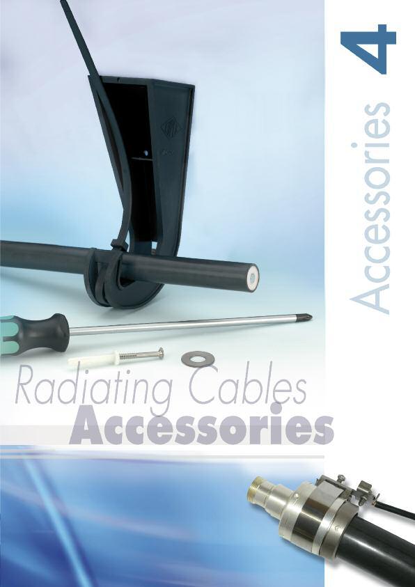
5. EPC (Eupen Passive Components) Dummy Loads DC Isolators Splitters Packing Information
|
|
|
- Winfred Horton
- 5 years ago
- Views:
Transcription

1 Edition 01 / 2014

2 2

3 1. Introduction 100 Years of Experience Over the World Introduction to Eupen Radiating Cables & Technical Parameters Cable Selection Guide Cables Characteristics LSC LSC RMC RMC 12-A RMC 12-T RMC 12-CL RMC 12-CH RMC RMC 58-T RMC RMC 78-T A Series RMC 78-B A Series RMC 78-CL A Series RMC 114 A Series RMC 114-T A Series RMC 114-B A Series RMC 158 A Series RMC 158-T A Series RMC 158-B A Series CMC Radiating Cable with Integrated Messenger Wire Accessories for Cables Connectors Cable Preparation Tools Jumper Cables Grounding Kits Additional Weatherproofing Solutions Hook Hanger Clic Clamp Stainless Steel Clamping Solutions EPC (Eupen Passive Components) Dummy Loads DC Isolators Splitters Packing Information Technical data, designs and specifications presented in this catalogue are not binding and are subject to change without prior notice. 3
4
5


6 Introduction 100 Years of Experience Eupen is a global cable manufacturer offering a wide range of cables and accessories. Underground communication systems using EUPEN radiating cables operate worldwide: Our product range includes: Radiating cables Transmission lines Safety cables Power cables Fibre optic cables Instrumentation cables As a leading supplier of transmission lines and accessories to global wireless communications markets, EUPEN has the experience and resources to effectively service customers in today s challenging wireless communications markets. Since broadband transmission became possible, EUPEN has been involved in the design and manufacture of transmission lines. The introduction of Cable Television in 1962 was decisive for the start of coaxial cables on a larger scale. At a time when wireless communication in confined areas, such as underground, street and service tunnels, became an important business to the network operators, EUPEN developed high quality radiating cables. in the Metros of: Brussels Caracas Instambul Kiev Moscow Rome Santiago de Chile Washington, DC... in road tunnels in Austria Belgium France Germany Greece Norway Singapore Spain the Netherlands... in Railway Tunnels of: Austria Belgium Germany Malaysia Spain Switzerland The Netherlands... Today, customers worldwide rely upon EUPEN products for wireless transmission of data, voice and video. and many other challenging locations. 6


7 Research & Development EUPEN s expertise in the wireless communications market is an invaluable resource to our customers. To anticipate and to follow the continuously changing demand of the market, we carefully evaluate customer feedback, which serves as stimulant for future improvements and developments of EUPEN s product portfolio. Innovative designs, a careful choice of raw materials together with consistent manufacturing and quality assurance techniques, ensure the electrical and mechanical superiority of Eupen cables for the needs of modern radio communication systems such as: FM VHF TETRA / TETRAPOL TDMA / CDMA 800 GSM 900/1800 GSM-R (European Railway) PCN / PCS 1900 UMTS 2200 LTE W-CDMA 2200 WLAN 2400 WLAN 5700 EUPEN Support EUPEN provides tailor made support for all kind of RF System needs. To meet customer demand for independent and unbiased support in the expert field of Specialised RF Coverage Solutions, Eupen has gathered a Team of dedicated advisors, who can provide complete support on all aspects of RF Coverage Solutions. Based on the Teams knowledge, that spans more than two decades, combined with good local knowledge of all major market places and by keeping close liaison with Consultants, Manufacturers, System Integrators and Installers world-wide, this Team is able to deliver advice that is combines state of the art technology, latest legislation and cost effectiveness. Together the cables and the connectors from EUPEN are an unbeatable match that optimises the entire system performance: Low attenuation Excellent field strength with low coupling loss Increased amplifier spacing due to very low system loss Simple connector installation Quick cable installation Halogen-free and fire retardant jacketing 7

8 Over the World Agencies Europe Austria Bulgaria Finland Germany Hungary Ireland Italy Norway Poland Romania Russia Spain Slovenia Sweden Tchech Republik Turkey Ukraine Agencies America Canada Mexico USA Florida New Jersey Texas Guatemala Agencies Africa Egypt South Africa 8

9 KABELWERK EUPEN AG Agencies Asia India Iran Pakistan Kingdom of Saudi Arabia Singapore Syria Thailand Taiwan R.O.C. UAE Malmedyer Strasse Eupen BELGIUM EUPEN CABLE MEXICO SA Avenida Manta 705 Lindavista, Mexico, D.F. MEXICO EUPEN CABLE USA Inc th Avenue North Unit D, Clearwater, Florida USA EUPEN CABLES FRANCE Z.A. La Haie Griselle 24, rue du 8 mai Boissy St Leger FRANCE KABELWERK RHENANIA GmbH Agencies Oceania Karl-Kuck-Str Aachen GERMANY Australia New Zealand 9

10 10

11 11

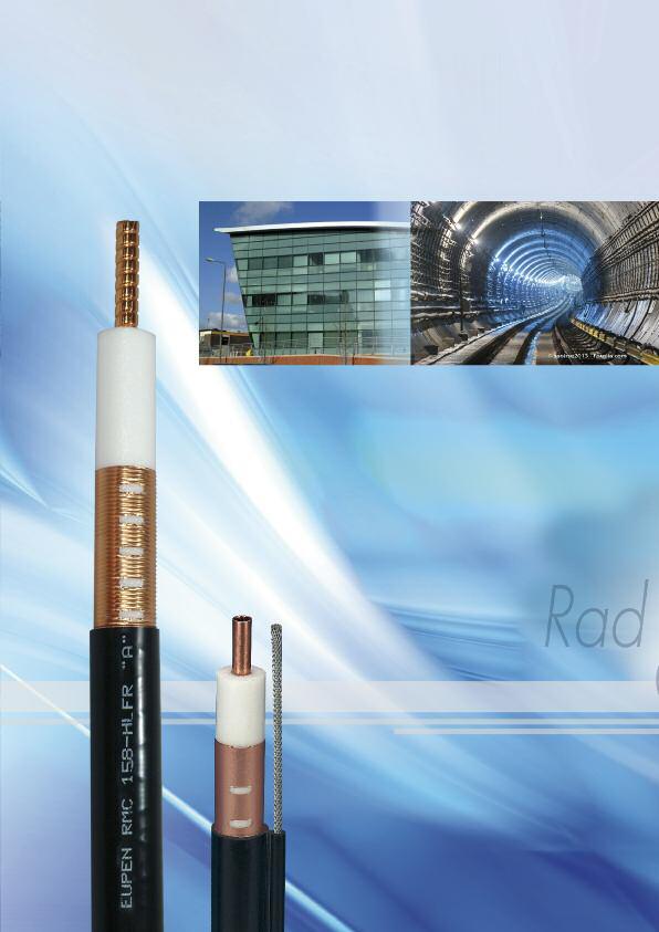
12 Eupen Cables General Radiating cables are used wherever normal radio communication is difficult or impossible, in particular in communication systems where a discrete antenna would not provide adequate coverage, such as in tunnels, underground railways, mines, buildings, etc. RF energy is simultaneously transmitted down radiating cables and radiated from all points along them into the surrounding space. Slots cut into the outer conductor of the coaxial cable allow controlled levels of electromagnetic energy to be radiated both out of and into the cable. A radiating cable functions both as a transmission line and as an antenna. The amount of radiation is quantified by the coupling loss. In the tables of the Data Sheets, the coupling loss is defined as the difference between the power transmitted into the cable and the power received by a λ2-dipole antenna located at a distance of 2 m from the cable. (This definition is taken from IEC ). An Application Note is available, free, on request. Cable construction Radiating cables have generally a coaxial design. They consist of a centre conductor, a dielectric, an outer conductor, which covers the dielectric, and a thermoplastic outer sheath. The characteristic impedance of the cables is normally 50 Ω, but 75 Ω cables are also possible. Sizes from 1/2 up to 1-5/8 are available. The inner conductor is made of solid copper, copperclad aluminium wire, smooth copper tube or corrugated copper tube, according to the conductor size. The dielectric is a cellular polyethylene foam, manufactured by an unique process using an ozone-friendly gas. The low density of the foam guarantees low longitudinal attenuation. The foam dielectric is bonded to the inner conductor by a pre-coating layer. This layer ensures good adhesion of the inner conductor to the dielectric. It also permits easy, clean removal of the dielectric during connector installation. For the outer conductor, a copper tape is used, longitudinally overlapped and bonded to the outer jacket to improve bend radius and water-tightness. 12

13 Halogen-free, Flame-retardant and Fire-resistant features The standard cable construction uses a weather-resistant Halogen-free, Low-smoke and Flame-Retardant (HLFR) outer jacket. This construction meets such international standards as IEC (for flame propagation), IEC (smoke density) and IEC (acidity of evolved gases). If a fire barrier tape (e.g., of mica) is added and placed between dielectric and outer conductor (HLFR/M outer jacket) the cable meets also the requirements of IEC electrical test (circuit integrity). The barrier tape does not affect the transmission characteristics of the cable. Flammability a) Test on flammability of single cables Test in accordance with: IEC EN b) Test on flammability of cable bundles Test in accordance with: also available: UL 1685, FT4, IEEE 1202 Smoke density IEC Cat. C EN Cat. C Test in accordance with: IEC and -2 EN and -2 also available: UL 1685, LS Corrosive gas emissions Test in accordance with: IEC EN Insulation integrity (HLFR/M jacket only) Test in accordance with: IEC VDE 0472 Part
14 Technical Parameters Theory of radiation In a coaxial cable a Transverse Electromagnetical (TEM)- wave travels from the transmitter to the cable end. In the case of a cable with a metallically fully closed outer conductor, the wave inside the cable is totally screened from the surrounding. Outside the coaxial cable, no electromagnetic field, or in other terms no electromagnetic radiation, can be measured. In the same case, no electromagnetic field outside the cable has any influence on the inside wave. By applying apertures to the outer conductor of a coaxial cable, a part of the energy from inside the cable is transferred to the outside surrounding. Also energy can intrude into the cable from the environment. Openings in the outer conductor cause electromagnetic coupling between the field of the inner wave and the outer wave of the outer space of the cable. The arrangement of the openings determines the mechanism of the coupling. The typical example of a radiating cable is a coaxial cable with a braided outer conductor. The largest part of the energy travels as an inside wave through the cable. At any point of inhomogeneity of the outer conductor, surface waves will be induced which travel in both, forward and backward direction along the outside of the cable and interfere with each other. The quality of the radio communication varies very much, due to level variation of the field outside the cable. The installation and the surrounding of the cable affects the radiated field along the cable. Most tunnels contain metallic conductors, such as power cables along the lateral walls, or rails, water pipes, etc. Such conductors can change drastically the electromagnetic field properties. The main electrical characteristics of a radiating cable are: Frequency ranges Longitudinal losses Coupling losses System losses Frequency ranges To determine the right cable for an application, the used frequency ranges has to be known precisely. The design of the apertures in the outer conductor influences the frequency range for which the cable is optimised. Three kinds of radiating coaxial cables are distinguished: CMC (Coupled Mode) Cables: These radiating cables are designed for in-building applications (where the system length is typically less than 100 m), for which a leaky section cable may not be appropriate. LSC (Leaky Section) Cables: Best performances up to 1 GHz. Although this cable can be used at higher frequencies, the sharp increase of its longitudinal losses generally limits its use above 1 GHz. RMC (Radiated Mode) Cables: Designed for a frequency range up to 6 GHz, these cables can be broadband, or are tuned for specific frequency ranges or applications. The particular design of the apertures creates some resonant frequencies. These resonant frequencies are well chosen and do not fall within the currently used communication bands. 14
15 Longitudinal loss The most important characteristic for energy transportation along a cable by the inner wave, is the longitudinal loss (or attenuation loss). A coaxial cable attenuates the signal travelling inside in function of the frequency. The higher the frequency, the higher the attenuation losses. The type of dielectric and the size of the cable mainly influence the longitudinal attenuation. The longitudinal loss depends also on the arrangement of the apertures in the outer conductor. Coupling loss The coupling loss describes the signal loss between the cable and a receiver. It is defined as the ratio of the received power, at a certain distance, to the power in the cable. Because of the reciprocity, analogue considerations are valid for the transmission from an antenna into the cable. The coupling loss is affected by the arrangement of the openings as well as by interferences and reflections of the cable surrounding. System loss The system loss is the sum of longitudinal and coupling loss and of various losses depending on the installation and the environment. Detailed information about the environmental influences are given in the chapter Installation. To design a radio communications systems the system loss needs to be calculated for the uplink and downlink connection. Resonant frequencies The cable design, more precisely the arrangement of the apertures in the outer conductor, can lead to resonant frequencies. This occurs when a certain wavelength interferes with the regular structure of the apertures. The reflection coefficient (SWR) jumps up and the longitudinal loss increases. While LSC and CMC cables don t show this behaviour, RMC cables are designed to present this resonance frequency (stop band) in frequency ranges, where the cables are generally not used. An Application Note is available, free, on request. An intensive radiation means a low coupling loss over a broad frequency range. Two different physical modes carry the energy from the cable into the air : coupling mode and radiating mode. 15

16 Cable Characteristics CMC Cables These radiating cables are designed for in-building applications (where the system length is typically less than 100 m), for which a leaky section cable may not be appropriate. Radiating cables of this type are suited for high-performance applications in the 450 MHz, 900 MHz and 1800 MHz bands. The electromagnetic field diffracted by the apertures of this cable type induces an external mode outside the outer conductor. A current flows on the outer part of the outer conductor and the cable radiates as a long traveling wave antenna. The coupled mode cable is therefore equivalent to a long electrical antenna. The coupled mode corresponds to a power flow, which is parallel to the cable axis. The electromagnetic energy is concentrated in the close vicinity of the cable and decreases quickly with distance: this is the reason why these modes are sometimes referred to as surface waves. The modes, confined around the cable axis, are partially diffracted by surrounding obstacles and discontinuities (clamps, walls,...): a fraction of the power is randomly radiated radially. LSC Cables Leaky sections are pre-punched into the outer conductor; the distance between sections is set to optimise low coupling loss and low longitudinal attenuation over a wide bandwidth. With this unique construction the distance between repeaters can be increased, and the broadband coupling loss is not significantly degraded from that obtained using continuously-slotted coupled-mode cables or radiating-mode cables. LSC cables are mode converters. They consist of a section of leaky cable, inserted in a non-leaky cable. A leaky section is equivalent to a directive antenna connected to the coaxial cable through a power divider. Only a small part of the power propagated inside the cable is extracted and converted into radiation. The spacing between leaky sections has to be chosen in order to provide acceptable results at various frequencies. Cables with leaky sections, designed in this way, can be used under the same conditions as continuous leaky feeders, but with better characteristics for longitudinal and coupling loss. The leaky sections are efficient mode converters and can produce a controlled field level in the cable vicinity, as a function of their length and their electrical characteristics. 16

17 RMC Cables Radiated Mode cables are designed for applications at frequencies of 75 MHz to 6 GHz. The slots are arranged so that the direction of radiation is predominantly orthogonal to the cable axis. This results in optimised, reduced coupling loss variations over specific frequency bands. RMC Cables for Digital Trunk Radio The advent of new Digital Trunk Radio Services, demands improved products to support these techniques. Eupen has met this challenge by including specially designed RMC cables that provide industry leading performances by being optimised for use with this new technology. With a radiated mode cable, the electric field is produced by periodic apertures (slots) on the cable s outer conductor. The aperture spacing d is comparable to the operational wavelength (λ c ). The radiated modes correspond to the in-phase addition of all apertures. They appear for only very well defined slot arrangements and over a well-defined Radiated mode frequency band. The coupling loss is low only in a certain frequency band. Above and below this frequency band it is increased due to interference. The direction of propagation is radially oriented. 17
18 Cable Selection Guide Frequency Bands MHz MHz MHz Applications FM PMR PMR PMR TETRA TETRAPOL page LSC RMC RMC 12-A 28 RMC RMC RMC 114 A Series 48 RMC 158 A Series 54 RMC 12-T 30 RMC 12-CL 32 RMC 12-CH 34 RMC 58-T 38 RMC 78-T A Series 42 RMC 78-B A Series 44 RMC 78-CL A Series 46 RMC 114-T A Series 50 RMC 114-B A Series 52 RMC 158-T A Series 56 RMC 158-B A Series 58 CMC best good not recommended Jacket Selection Guide Jacket Type IEC /-2 IEC (suffix of Cable Name) Requirements Halogen free Low smoke density non corrosive smoke emission PE HLFR HLFR/M 18
19 MHz GHz GHz GHz 6 GHz TDMA PCN UMTS ISM WLAN CDMA DECT WLAN GSM 900 GSM 1800 WIFI GSM - R TETRA Important: please always check for resonant frequencies IEC IEC C IEC Flame retardant Fire retardant DC Circuit integrity 19
20
21
22 LSC 12 PRODUCT DESCRIPTION Reference suffix (1) : -HLFR LSC 12-HLFR Fire behaviour Halogen free and flame retardant outer sheath, Low corrosive gas emission acc. to IEC Flame retardant acc. to IEC and IEC cat. C, Low smoke emission acc. to IEC Slots in the copper outer conductor allow a controlled portion of the internal RF energy to be radiated into the surrounding environment. Conversely, a signal transmitted near the cable will couple into the slots and be carried along the cable length. FEATURES and BENEFITS Broadband from 30 MHz to 1.9 GHz Robust Cable, with low bending radius No Resonant Frequencies No Cable Orientation Required Main Applications: Tunnel - FM, TETRA, GSM, GSM-R, DCS-1800 Only for use in Tunnels - Not suitable for use in Buildings TECHNICAL FEATURES Size 1/2 Previous Model Number 512RC8R-HLFR Frequency Range MHz Recommended for Frequency MHz N.A. Cable Type LSC (Leaky Section Cable) Jacket HLFR (Halogen Free Low Smoke Flame Retardant) Slot Design Groups of Slots at longer intervals Impedance Ω 50 +/- 2 Velocity Ratio % 88 Capacitance pf/m 76 Inner Conductor dc Resistance Ω/1000 m (Ω/1000 ft) 1.48 (0.45) HLFR Outer Conductor dc Resistance Ω/1000 m (Ω/1000 ft) 2.62 (0.80) Inner Conductor Material Copper clad aluminium wire (HLFR) Dielectric Material Cellular polyethylene Outer Conductor Material Overlapping copper foil, with slot groups, bonded to the jacket 22
23 LSC 12 TECHNICAL FEATURES (continued) Diameter Inner Conductor mm (in) 4.8 (0.19) Diameter Dielectric mm (in) 12.4 (0.49) Diameter over Jacket mm (in) 15.5 (0.61) Minimum Bending Radius, Single Bend mm (in) 200 (7.87) Cable Weight kg/m (lb/ft) 0.33 (0.22) HLFR Tensile Strength dan (lb) 110 (242) Indication of Slot Alignment N.A. Storage Temperature C ( F) -70 to +85 (-94 to +185) Installation Temperature C ( F) -25 to +60 (-13 to +140) Operation Temperature C ( F) -40 to +85 (-40 to +185) Longitudinal Loss and Coupling Loss (2) Frequency Longitudinal Loss Coupling Loss db/100 m (db/100 ft) C50% [db] C95% [db] 75 MHz 1.87 (0.57) MHz 2.69 (0.82) MHz 3.35 (1.02) MHz 4.93 (1.50) MHz 7.43 (2.26) MHz 11.7 (3.57) MHz 12.2 (3.70) MHz MHz Resonant Frequencies MHz None Clamp Spacing Recommended / Maximum m (ft) 0.5 (1.64) / 1.20 (3.90) Distance to Wall Recommended / Minimum mm (in) ( ) / 50 (1.96) 1) Must be specified in case of order - standard PE jacket available on request. (2) Measured in tunnel according to IEC Ground Level Method. Distance = 2m. C50 & (C95) are the average coupling losses with 50% (95%) probability calculated in accordance with the standard. The above stated values are nominal values and subject to manufacturing tolerances as follows: Longitudinal Loss +/-5 % and Coupling Loss +/- 3dB. As with any radiating cable, the performance in building or tunnel may deviate from figures measured according to the IEC standard. Coupling loss measurements taken in accordance with IEC Free Space Method are available on request These Radiating Cables have been especially developed for use in Tunnels. Due to the Cables inherent design, based on Groups of Slots at longer intervals, these Radiating Cables are not suitable for In-Building use. 23
24 LSC 78 PRODUCT DESCRIPTION Reference suffix (1) : -HLFR LSC 78-HLFR Fire behaviour Halogen free and flame retardant outer sheath, Low corrosive gas emission acc. to IEC Flame retardant acc. to IEC and IEC cat. C, Low smoke emission acc. to IEC Slots in the copper outer conductor allow a controlled portion of the internal RF energy to be radiated into the surrounding environment. Conversely, a signal transmitted near the cable will couple into the slots and be carried along the cable length. FEATURES and BENEFITS Broadband from 30 MHz to 1.9 GHz Robust Cable, with low bending radius No Resonant Frequencies No Cable Orientation Required Main Applications: Tunnel - FM, TETRA, GSM, GSM-R, DCS-1800 Only for use in Tunnels - Not suitable for use in Buildings TECHNICAL FEATURES Size 7/8 Previous Model Number 522RC8R-HLFR Frequency Range MHz Recommended for Frequency MHz N.A. Cable Type LSC (Leaky Section Cable) Jacket HLFR (Halogen Free Low Smoke Flame Retardant) Slot Design Groups of Slots at longer intervals Impedance Ω 50 +/- 2 Velocity Ratio % 88 Capacitance pf/m 76 Inner Conductor dc Resistance Ω/1000 m (Ω/1000 ft) 1.63 (0.49) Outer Conductor dc Resistance Ω/1000 m (Ω/1000 ft) 1.40 (0.43) Inner Conductor Material Smooth copper tube Dielectric Material Cellular polyethylene Outer Conductor Material Overlapping copper foil, with slot groups, bonded to the jacket 24
25 LSC 78 TECHNICAL FEATURES (continued) Diameter Inner Conductor mm (in) 9.2 (0.36) Diameter Dielectric mm (in) 23.5 (0.93) Diameter over Jacket mm (in) 27.0 (1.06) Minimum Bending Radius, Single Bend mm (in) 350 (13.80) Cable Weight kg/m (lb/ft) (0.32) HLFR Tensile Strength dan (lb) 130 (287) Indication of Slot Alignment N.A. Storage Temperature C ( F) -70 to +85 (-94 to +185) Installation Temperature C ( F) -25 to +60 (-13 to +140) Operation Temperature C ( F) -40 to +85 (-40 to +185) Longitudinal Loss and Coupling Loss (2) Frequency Longitudinal Loss Coupling Loss db/100 m (db/100 ft) C50% [db] C95% [db] 75 MHz 1.06 (0.32) MHz 1.58 (0.48) MHz 2.01 (0.61) MHz 3.09 (0.94) MHz 4.86 (1.48) MHz (3.08) MHz (3.41) MHz MHz Resonant Frequencies MHz None Clamp Spacing Recommended / Maximum m (ft) 0.5 (1.64) / 1.20 (3.90) Distance to Wall Recommended / Minimum mm (in) ( ) / 50 (1.96) 1) Must be specified in case of order - standard PE jacket available on request. (2) Measured in tunnel according to IEC Ground Level Method. Distance = 2m. C50 & (C95) are the average coupling losses with 50% (95%) probability calculated in accordance with the standard. The above stated values are nominal values and subject to manufacturing tolerances as follows: Longitudinal Loss +/-5 % and Coupling Loss +/- 3dB. As with any radiating cable, the performance in building or tunnel may deviate from figures measured according to the IEC standard. Coupling loss measurements taken in accordance with IEC Free Space Method are available on request These Radiating Cables have been especially developed for use in Tunnels. Due to the Cables inherent design, based on Groups of Slots at longer intervals, these Radiating Cables are not suitable for In-Building use. 25
26 RMC 12 PRODUCT DESCRIPTION RMC 12-HLFR Reference suffix (1) : -HLFR Fire behaviour Halogen free and flame retardant outer sheath, Low corrosive gas emission acc. to IEC Flame retardant acc. to IEC and IEC cat. C, Low smoke emission acc. to IEC Slots in the copper outer conductor allow a controlled portion of the internal RF energy to be radiated into the surrounding environment. Conversely, a signal transmitted near the cable will couple into the slots and be carried along the cable length. FEATURES and BENEFITS From 30 MHz to 2.5 GHz with resonant frequencies Robust Cable, with low bending radius Main Applications: Tunnel - GSM, GSM-R, DCS-1800, WLAN TECHNICAL FEATURES Size 1/2 Previous Model Number 512RC8RM-HLFR Frequency Range MHz Recommended for Frequency MHz 900 and above Cable Type RMC (Radiated Mode Cable) Jacket HLFR (Halogen Free Low Smoke Flame Retardant) Slot Design Groups of Slots at short intervals Impedance Ω 50 +/- 3 Velocity Ratio % 88 Capacitance pf/m 76 Inner Conductor dc Resistance Ω/1000 m (Ω/1000 ft) 1.48 (0.45) HLFR Outer Conductor dc Resistance Ω/1000 m (Ω/1000 ft) 2.90 (0.88) Inner Conductor Material Copper clad aluminium (HLFR) Dielectric Material Cellular polyethylene Outer Conductor Material Overlapping copper foil, with slot groups, bonded to the jacket 26
27 RMC 12 TECHNICAL FEATURES (continued) Diameter Inner Conductor mm (in) 4.8 (0.19) Diameter Dielectric mm (in) 12.4 (0.49) Diameter over Jacket mm (in) 15.5 (0.61) Minimum Bending Radius, Single Bend mm (in) 200 (7.87) Cable Weight kg/m (lb/ft) 0.23 (0.16) HLFR Tensile Strength dan (lb) 110 (243) Indication of Slot Alignment embossed line 180 opposite Storage Temperature C ( F) -70 to +85 (-94 to +185) Installation Temperature C ( F) -25 to +60 (-13 to +140) Operation Temperature C ( F) -40 to +85 (-40 to +185) Longitudinal Loss and Coupling Loss (2) Frequency Longitudinal Loss Coupling Loss db/100 m (db/100 ft) C50% [db] C95% [db] 75 MHz 2.35 (0.72) MHz 3.25 (0.99) MHz 3.70 (1.13) MHz 5.00 (1.53) MHz 7.70 (2.36) MHz (3.76) MHz (3.90) MHz (4.54) MHz (5.07) Resonant Frequencies MHz 547, 1641, 2734 Clamp Spacing Recommended / Maximum m (ft) 0.5 (1.64) / 1.20 (3.90) Distance to Wall Recommended / Minimum mm (in) ( ) / 50 (1.96) 1) Must be specified in case of order - standard PE jacket available on request. (2) Measured in tunnel according to IEC Ground Level Method. Distance = 2m. C50 & (C95) are the average coupling losses with 50% (95%) probability calculated in accordance with the standard. The above stated values are nominal values and subject to manufacturing tolerances as follows: Longitudinal Loss +/-5 % and Coupling Loss +/- 3dB. As with any radiating cable, the performance in building or tunnel may deviate from figures measured according to the IEC standard. Coupling loss measurements taken in accordance with IEC Free Space Method are available on request 27
28 RMC 12-A PRODUCT DESCRIPTION RMC 12-A-HLFR Reference suffix (1) : -HLFR Fire behaviour Halogen free and flame retardant outer sheath Low corrosive gas emission acc. to IEC Flame retardant acc. to IEC and IEC cat. C Low smoke emission acc. to IEC Slots in the copper outer conductor allow a controlled portion of the internal RF energy to be radiated into the surrounding environment. Conversely, a signal transmitted near the cable will couple into the slots and be carried along the cable length. FEATURES and BENEFITS From 30 MHz to 2.5 GHz with resonant frequencies Robust Cable, with low bending radius Main Applications: AIRCRAFT - GSM, DCS-1800, UMTS, WLAN-short length Specially designed for use in Aircraft TECHNICAL FEATURES Size 1/2 Previous Model Number 512RC8RMA-HLFR Frequency Range MHz Recommended for Frequency MHz 450 and above Cable Type RMC (Radiated Mode Cable) Jacket HLFR (Halogen Free Low Smoke Flame Retardant) Slot Design Groups of Slots at short intervals Impedance Ω 50 +/- 3 Velocity Ratio % 88 Capacitance pf/m 76 Inner Conductor dc Resistance Ω/1000 m (Ω/1000 ft) 1.48 (0.45) Outer Conductor dc Resistance Ω/1000 m (Ω/1000 ft) 3 (0.91) Inner Conductor Material Copper clad aluminium wire Dielectric Material Cellular polyethylene Outer Conductor Material Overlapping copper foil, with slot groups, bonded to the jacket 28
29 RMC 12-A TECHNICAL FEATURES (continued) Diameter Inner Conductor mm (in) 4.8 (0.19) Diameter Dielectric mm (in) 12.4 (0.49) Diameter over Jacket mm (in) 15.5 (0.61) Minimum Bending Radius, Single Bend mm (in) 200 (7.87) Cable Weight kg/m (lb/ft) 0.21 (0.14) HLFR Tensile Strength dan (lb) 110 (242) Indication of Slot Alignment embossed line 180 opposite Storage Temperature C ( F) -70 to +85 (-94 to +185) Installation Temperature C ( F) -25 to +60 (-13 to +140) Operation Temperature C ( F) -40 to +85 (-40 to +185) Longitudinal Loss and Coupling Loss (2) Frequency Longitudinal Loss Coupling Loss db/100 m (db/100 ft) C50% [db] C95% [db] 75 MHz 3.59 (1.09) MHz 4.26 (1.30) MHz 4.67 (1.42) MHz 5.85 (1.78) MHz 9.52 (2.90) MHz 20.8 (6.34) MHz 22.7 (6.92) MHz 30.4 (9.27) MHz 37.8 (11.52) Resonant Frequencies MHz 184, 552, 920 ±5, 1288, 1656, 2024, 2392 Clamp Spacing Recommended / Maximum m (ft) 0.5 (1.64) / 1.20 (3.90) Distance to Wall Recommended / Minimum mm (in) ( ) / 50 (1.96) 1) Must be specified in case of order - standard PE jacket available on request. (2) Measured in tunnel according to IEC Ground Level Method. Distance = 2m. C50 & (C95) are the average coupling losses with 50% (95%) probability calculated in accordance with the standard. The above stated values are nominal values and subject to manufacturing tolerances as follows: Longitudinal Loss +/-5 % and Coupling Loss +/- 3dB. As with any radiating cable, the performance in building or tunnel may deviate from figures measured according to the IEC standard. Coupling loss measurements taken in accordance with IEC Free Space Method are available on request 29
30 RMC 12-T PRODUCT DESCRIPTION RMC 12-T-HLFR Reference suffix (1) : -HLFR Fire behaviour Halogen free and flame retardant outer sheath, Low corrosive gas emission acc. to IEC Flame retardant acc. to IEC and IEC cat. C, Low smoke emission acc. to IEC Slots in the copper outer conductor allow a controlled portion of the internal RF energy to be radiated into the surrounding environment. Conversely, a signal transmitted near the cable will couple into the slots and be carried along the cable length. FEATURES and BENEFITS From 30 MHz to 1 GHz with resonant frequencies Robust Cable, with low bending radius Main Applications: Tunnel - FM, TETRA TECHNICAL FEATURES Size 1/2 Previous Model Number 512RC8RMT-HLFR Frequency Range MHz Recommended for Frequency MHz 450 Cable Type RMC (Radiated Mode Cable) Jacket HLFR (Halogen Free Low Smoke Flame Retardant) Slot Design Groups of Slots at short intervals Impedance Ω 50 +/- 3 Velocity Ratio % 88 Capacitance pf/m 76 Inner Conductor dc Resistance Ω/1000 m (Ω/1000 ft) 1.48 (0.45) HLFR Outer Conductor dc Resistance Ω/1000 m (Ω/1000 ft) 2.80 (0.85) Inner Conductor Material Copper clad aluminium (HLFR) Dielectric Material Cellular polyethylene Outer Conductor Material Overlapping copper foil, with slot groups, bonded to the jacket 30
31 RMC 12-T TECHNICAL FEATURES (continued) Diameter Inner Conductor mm (in) 4.8 (0.19) Diameter Dielectric mm (in) 12.4 (0.49) Diameter over Jacket mm (in) 15.5 (0.61) Minimum Bending Radius, Single Bend mm (in) 200 (7.87) Cable Weight kg/m (lb/ft) 0.22 (0.15) HLFR Tensile Strength dan (lb) 110 (243) Indication of Slot Alignment embossed line 180 opposite Storage Temperature C ( F) -70 to +85 (-94 to +185) Installation Temperature C ( F) -25 to +60 (-13 to +140) Operation Temperature C ( F) -40 to +85 (-40 to +185) Longitudinal Loss and Coupling Loss (2) Frequency Longitudinal Loss Coupling Loss db/100 m (db/100 ft) C50% [db] C95% [db] 75 MHz 2.2 (0.67) MHz 3.0 (0.91) MHz 3.8 (1.16) MHz 5.4 (1.65) MHz 5.9 (1.80) MHz 10.6 (3.23) MHz MHz MHz MHz Resonant Frequencies MHz 37, 111, 185, 259, 334, 408, 482, 556, 630, 704, 778, 853, 927, 1001 Clamp Spacing Recommended / Maximum m (ft) 0.5 (1.64) / 1.20 (3.90) Distance to Wall Recommended / Minimum mm (in) ( ) / 50 (1.96) 1) Must be specified in case of order - standard PE jacket available on request. (2) Measured in tunnel according to IEC Ground Level Method. Distance = 2m. C50 & (C95) are the average coupling losses with 50% (95%) probability calculated in accordance with the standard. All Values are going to be confirmed by independent Test Centre soonest. The above stated values are nominal values and subject to manufacturing tolerances as follows: Longitudinal Loss +/-5 % and Coupling Loss +/- 3dB. As with any radiating cable, the performance in building or tunnel may deviate from figures measured according to the IEC standard. Coupling loss measurements taken in accordance with IEC Free Space Method are available on request 31
32 RMC 12-CL PRODUCT DESCRIPTION RMC 12-CL-HLFR Reference suffix (1) : -HLFR Fire behaviour Halogen free and flame retardant outer sheath Low corrosive gas emission acc. to IEC Flame retardant acc. to IEC and IEC cat. C Low smoke emission acc. to IEC Slots in the copper outer conductor allow a controlled portion of the internal RF energy to be radiated into the surrounding environment. Conversely, a signal transmitted near the cable will couple into the slots and be carried along the cable length. FEATURES and BENEFITS Low Fading at short Aerial to Cable distance Robust Cable Main Applications: WLAN controlled Transportation Systems Optimised for WLAN applications in the GHz band TECHNICAL FEATURES Size 1/2 Previous Model Number N.A. Frequency Range MHz Recommended for Frequency MHz Cable Type RMC (Radiated Mode Cable) Jacket HLFR (Halogen Free Low Smoke Flame Retardant) Slot Design Groups of Slots at short intervals Impedance Ω 50 +/- 3 Velocity Ratio % 88 Capacitance pf/m 76 Inner Conductor dc Resistance Ω/1000 m (Ω/1000 ft) 1.48 (0.45) Outer Conductor dc Resistance Ω/1000 m (Ω/1000 ft) 2.8 (0.85) Inner Conductor Material Copper clad aluminium wire Dielectric Material Cellular polyethylene Outer Conductor Material Overlapping copper foil, with slot groups, bonded to the jacket 32
33 RMC 12-CL TECHNICAL FEATURES (continued) Diameter Inner Conductor mm (in) 4.8 (0.19) Diameter Dielectric mm (in) 12.4 (0.49) Diameter over Jacket mm (in) 15.5 (0.61) Minimum Bending Radius, Single Bend mm (in) 200 (7.87) Cable Weight kg/m (lb/ft) 0.23 (0.16) HLFR Tensile Strength dan (lb) 110 (243) Indication of Slot Alignment embossed line 180 opposite Storage Temperature C ( F) -70 to +85 (-94 to +185) Installation Temperature C ( F) -25 to +60 (-13 to +140) Operation Temperature C ( F) -40 to +85 (-40 to +185) Longitudinal Loss and Coupling Loss (2) Frequency Longitudinal Loss Coupling Loss db/100 m (db/100 ft) C50% [db] C95% [db] 75 MHz 1.87 (0.57) MHz 2.75 (0.83) MHz 3.42 (1.04) MHz 4.96 (1.51) MHz 7.32 (2.22) MHz (3.63) MHz (3.78) MHz (4.22) MHz (4.47) Resonant Frequencies MHz 156, 469, 781, 1094, 1406, 1718, 2031, 2344, 2656 Clamp Spacing Recommended / Maximum m (ft) 0.5 (1.64) / 1.20 (3.90) Distance to Wall Recommended / Minimum mm (in) ( ) / 50 (1.96) 1) Must be specified in case of order - standard PE jacket available on request. (2) Measured in tunnel according to IEC Ground Level Method. Distance = 2m. C50 & (C95) are the average coupling losses with 50% (95%) probability calculated in accordance with the standard. The above stated values are nominal values and subject to manufacturing tolerances as follows: Longitudinal Loss +/-5 % and Coupling Loss +/- 3dB. As with any radiating cable, the performance in building or tunnel may deviate from figures measured according to the IEC standard. Coupling loss measurements taken in accordance with IEC Free Space Method are available on request 33
34 RMC 12-CH PRODUCT DESCRIPTION RMC 12-CH-HLFR Reference suffix (1) : -HLFR Fire behaviour Halogen free and flame retardant outer sheath Low corrosive gas emission acc. to IEC Flame retardant acc. to IEC and IEC cat. C Low smoke emission acc. to IEC Slots in the copper outer conductor allow a controlled portion of the internal RF energy to be radiated into the surrounding environment. Conversely, a signal transmitted near the cable will couple into the slots and be carried along the cable length. FEATURES and BENEFITS Low Fading at short Aerial to Cable distance Robust Cable Main Applications: WLAN controlled Transportation Systems Optimised for WLAN applications in the and GHz bands TECHNICAL FEATURES Size 1/2 Previous Model Number N.A. Frequency Range MHz Recommended for Frequency MHz and Cable Type RMC (Radiated Mode Cable) Jacket HLFR (Halogen Free Low Smoke Flame Retardant) Slot Design Groups of Slots at short intervals Impedance Ω 50 +/- 3 Velocity Ratio % 88 Capacitance pf/m 76 Inner Conductor dc Resistance Ω/1000 m (Ω/1000 ft) 1.48 (0.45) Outer Conductor dc Resistance Ω/1000 m (Ω/1000 ft) 2.8 (0.85) Inner Conductor Material Copper clad aluminium wire Dielectric Material Cellular polyethylene Outer Conductor Material Overlapping copper foil, with slot groups, bonded to the jacket 34
35 RMC 12-CH TECHNICAL FEATURES (continued) Diameter Inner Conductor mm (in) 4.8 (0.19) Diameter Dielectric mm (in) 12.4 (0.49) Diameter over Jacket mm (in) 15.5 (0.61) Minimum Bending Radius, Single Bend mm (in) 200 (7.87) Cable Weight kg/m (lb/ft) 0.23 (0.16) HLFR Tensile Strength dan (lb) 110 (243) Indication of Slot Alignment embossed line 180 opposite Storage Temperature C ( F) -70 to +85 (-94 to +185) Installation Temperature C ( F) -25 to +60 (-13 to +140) Operation Temperature C ( F) -40 to +85 (-40 to +185) Longitudinal Loss and Coupling Loss (2) Frequency Longitudinal Loss Coupling Loss db/100 m (db/100 ft) C50% [db] C95% [db] 5200 MHz 19.1 (5,82) MHz 20.0 (6,10) MHz 21.5 (6,55) Resonant Frequencies MHz 415, 1246, 2077, 2907, 3738, 4568, 5399, 6230 Clamp Spacing Recommended / Maximum m (ft) 0.5 (1.64) / 1.20 (3.90) Distance to Wall Recommended / Minimum mm (in) ( ) / 50 (1.96) 1) Must be specified in case of order - standard PE jacket available on request. (2) Measured in tunnel according to IEC Ground Level Method. Distance = 2m. C50 & (C95) are the average coupling losses with 50% (95%) probability calculated in accordance with the standard. The above stated values are nominal values and subject to manufacturing tolerances as follows: Longitudinal Loss +/-5 % and Coupling Loss +/- 3dB. As with any radiating cable, the performance in building or tunnel may deviate from figures measured according to the IEC standard. Coupling loss measurements taken in accordance with IEC Free Space Method are available on request 35
36 RMC 58 PRODUCT DESCRIPTION RMC 58-HLFR Reference suffix (1) : -HLFR Fire behaviour Halogen free and flame retardant outer sheath, Low corrosive gas emission acc. to IEC Flame retardant acc. to IEC and IEC cat. C, Low smoke emission acc. to IEC Slots in the copper outer conductor allow a controlled portion of the internal RF energy to be radiated into the surrounding environment. Conversely, a signal transmitted near the cable will couple into the slots and be carried along the cable length. FEATURES and BENEFITS Broadband from 30 MHz to 1.9 GHz Robust Cable, with low bending radius Main Applications: Tunnel - GSM, GSM-R, DCS-1800 TECHNICAL FEATURES Size 5/8 Previous Model Number 517RC8RM-HLFR Frequency Range MHz Recommended for Frequency MHz 900 and 1800 Cable Type RMC (Radiated Mode Cable) Jacket HLFR (Halogen Free Low Smoke Flame Retardant) Slot Design Groups of Slots at short intervals Impedance Ω 50 +/- 2 Velocity Ratio % 88 Capacitance pf/m 76 Inner Conductor dc Resistance Ω/1000 m (Ω/1000 ft) 1.9 (0.58) Outer Conductor dc Resistance Ω/1000 m (Ω/1000 ft) 2.04 (0.62) Inner Conductor Material Smooth copper tube Dielectric Material Cellular polyethylene Outer Conductor Material Overlapping copper foil, with slot groups, bonded to the jacket 36
37 RMC 58 TECHNICAL FEATURES (continued) Diameter Inner Conductor mm (in) 6.8 (0.27) Diameter Dielectric mm (in) 17.6 (0.69) Diameter over Jacket mm (in) 21.0 (0.83) Minimum Bending Radius, Single Bend mm (in) 300 (11.8) Cable Weight kg/m (lb/ft) (0.25) Tensile Strength dan (lb) 90 (198) Indication of Slot Alignment embossed line 180 opposite Storage Temperature C ( F) -70 to +85 (-94 to +185) Installation Temperature C ( F) -25 to +60 (-13 to +140) Operation Temperature C ( F) -40 to +85 (-40 to +185) Longitudinal Loss and Coupling Loss (2) Frequency Longitudinal Loss Coupling Loss db/100 m (db/100 ft) C50% [db] C95% [db] 75 MHz 1.36 (0.41) MHz 1.99 (0.61) MHz 2.48 (0.76) MHz 3.58 (1.09) MHz 5.26 (1.60) MHz 9.09 (2.77) MHz 9.55 (2.91) MHz 2400 MHz Resonant Frequencies MHz 116, 348, 580, 812, 1044, 1276, 1508,1740 ±5 Clamp Spacing Recommended / Maximum m (ft) 0.5 (1.64) / 1.20 (3.90) Distance to Wall Recommended / Minimum mm (in) ( ) / 50 (1.96) 1) Must be specified in case of order - standard PE jacket available on request. (2) Measured in tunnel according to IEC Ground Level Method. Distance = 2m. C50 & (C95) are the average coupling losses with 50% (95%) probability calculated in accordance with the standard. The above stated values are nominal values and subject to manufacturing tolerances as follows: Longitudinal Loss +/-5 % and Coupling Loss +/- 3dB. As with any radiating cable, the performance in building or tunnel may deviate from figures measured according to the IEC standard. Coupling loss measurements taken in accordance with IEC Free Space Method are available on request 37
38 RMC 58-T PRODUCT DESCRIPTION RMC 58-T-HLFR Reference suffix (1) : -HLFR Fire behaviour Halogen free and flame retardant outer sheath, Low corrosive gas emission acc. to IEC Flame retardant acc. to IEC and IEC cat. C, Low smoke emission acc. to IEC Slots in the copper outer conductor allow a controlled portion of the internal RF energy to be radiated into the surrounding environment. Conversely, a signal transmitted near the cable will couple into the slots and be carried along the cable length. FEATURES and BENEFITS Broadband from 30 MHz to 1 GHz with resonant frequencies Robust Cable, with low bending radius Main Applications: Tunnel - FM, TETRA TECHNICAL FEATURES Size 5/8 Previous Model Number 517RC8RMT-HLFR / 517MRC8RMT-HLFR (with Mica) Frequency Range MHz Recommended for Frequency MHz 450 Cable Type RMC (Radiated Mode Cable) Jacket HLFR (Halogen Free Low Smoke Flame Retardant) Slot Design Groups of Slots at short intervals Impedance Ω 50 +/- 2 Velocity Ratio % 88 Capacitance pf/m 76 Inner Conductor dc Resistance Ω/1000 m (Ω/1000 ft) 1.9 (0.58) Outer Conductor dc Resistance Ω/1000 m (Ω/1000 ft) 2.18 (0.66) Inner Conductor Material Smooth copper tube Dielectric Material Cellular polyethylene Outer Conductor Material Overlapping copper foil, with slot groups, bonded to the jacket 38
39 RMC 58-T TECHNICAL FEATURES (continued) Diameter Inner Conductor mm (in) 6.8 (0.27) Diameter Dielectric mm (in) 17.6 (0.69) Diameter over Jacket mm (in) 21.0 (0.83) Minimum Bending Radius, Single Bend mm (in) 300 (11.8) Cable Weight kg/m (lb/ft) (0.23) Tensile Strength dan (lb) 90 (198) Indication of Slot Alignment embossed line 180 opposite Storage Temperature C ( F) -70 to +85 (-94 to +185) Installation Temperature C ( F) -25 to +60 (-13 to +140) Operation Temperature C ( F) -40 to +85 (-40 to +185) Longitudinal Loss and Coupling Loss (2) Frequency Longitudinal Loss Coupling Loss db/100 m (db/100 ft) C50% [db] C95% [db] 75 MHz 1.7 (0.52) MHz 2.5 (0.76) MHz 3.1 (0.94) MHz 4.2 (1.28) MHz 4.6 (1.40) MHz 10.5 (3.20) MHz MHz MHz MHz Resonant Frequencies MHz 37, 111, 184, 258, 332, 405 ±3, 479, 553, 627, 700, 774, 848, 922, 995 ±5 Clamp Spacing Recommended / Maximum m (ft) 0.5 (1.64) / 1.20 (3.90) Distance to Wall Recommended / Minimum mm (in) ( ) / 50 (1.96) 1) Must be specified in case of order - standard PE jacket available on request. (2) Measured in tunnel according to IEC Ground Level Method. Distance = 2m. C50 & (C95) are the average coupling losses with 50% (95%) probability calculated in accordance with the standard. The above stated values are nominal values and subject to manufacturing tolerances as follows: Longitudinal Loss +/-5 % and Coupling Loss +/- 3dB. As with any radiating cable, the performance in building or tunnel may deviate from figures measured according to the IEC standard. Coupling loss measurements taken in accordance with IEC Free Space Method are available on request 39
40 RMC 78 PRODUCT DESCRIPTION RMC 78-HLFR Reference suffix (1) : -HLFR Fire behaviour Halogen free and flame retardant outer sheath, Low corrosive gas emission acc. to IEC Flame retardant acc. to IEC and IEC cat. C, Low smoke emission acc. to IEC Slots in the copper outer conductor allow a controlled portion of the internal RF energy to be radiated into the surrounding environment. Conversely, a signal transmitted near the cable will couple into the slots and be carried along the cable length. FEATURES and BENEFITS From 30 MHz to 2.8 GHz with resonant frequencies Robust Cable, with low bending radius Main Applications: Tunnel - FM, TETRA, GSM, DCS-1800, UMTS, WLAN TECHNICAL FEATURES Size 7/8 Previous Model Number 522RC8RM-HLFR Frequency Range MHz Recommended for Frequency MHz 900, 1800, 2200, 2400 and 2700 Cable Type RMC (Radiated Mode Cable) Jacket HLFR (Halogen Free Low Smoke Flame Retardant) Slot Design Groups of Slots at short intervals Impedance Ω 50 +/- 2 Velocity Ratio % 88 Capacitance pf/m 76 Inner Conductor dc Resistance Ω/1000 m (Ω/1000 ft) 1.63 (0.49) Outer Conductor dc Resistance Ω/1000 m (Ω/1000 ft) 1.50 (0.46) Inner Conductor Material Smooth copper tube Dielectric Material Cellular polyethylene Outer Conductor Material Overlapping copper foil, with slot groups, bonded to the jacket 40
41 RMC 78 TECHNICAL FEATURES (continued) Diameter Inner Conductor mm (in) 9.2 (0.36) Diameter Dielectric mm (in) 23.5 (0.93) Diameter over Jacket mm (in) 27.0 (1.06) Minimum Bending Radius, Single Bend mm (in) 350 (13.8) Cable Weight kg/m (lb/ft) (0.32) HLFR Tensile Strength dan (lb) 130 (287) Indication of Slot Alignment embossed line 180 opposite Storage Temperature C ( F) -70 to +85 (-94 to +185) Installation Temperature C ( F) -25 to +60 (-13 to +140) Operation Temperature C ( F) -40 to +85 (-40 to +185) Longitudinal Loss and Coupling Loss (2) Frequency Longitudinal Loss Coupling Loss db/100 m (db/100 ft) C50% [db] C95% [db] 75 MHz 1.02 (0.31) MHz 1.42 (0.43) MHz 1.74 (0.53) MHz 2.50 (0.76) MHz 3.82 (1.16) MHz 6.17 (1.88) MHz 6.42 (1.96) MHz 7.22 (2.20) MHz 7.81 (2.38) MHz 8.47 (2.58) MHz 9.43 (2.87) Resonant Frequencies MHz 184, 552, 920 ±5, 1288, 1656, 2024, 2392 Clamp Spacing Recommended / Maximum m (ft) 0.5 (1.64) / 1.20 (3.90) Distance to Wall Recommended / Minimum mm (in) ( ) / 50 (1.96) 1) Must be specified in case of order - standard PE jacket available on request. (2) Measured in tunnel according to IEC Ground Level Method. Distance = 2m. C50 & (C95) are the average coupling losses with 50% (95%) probability calculated in accordance with the standard. The above stated values are nominal values and subject to manufacturing tolerances as follows: Longitudinal Loss +/-5 % and Coupling Loss +/- 3dB. As with any radiating cable, the performance in building or tunnel may deviate from figures measured according to the IEC standard. Coupling loss measurements taken in accordance with IEC Free Space Method are available on request 41
42 RMC 78-T A Series PRODUCT DESCRIPTION RMC 78-T-HLFR A Series Reference suffix (1) : -HLFR Glasfiber tape Slotted copper outer conductor Low density cellular PE Fire behaviour Outer jacket Inner conductor Halogen free and flame retardant outer sheath, Low corrosive gas emission acc. to IEC Flame retardant acc. to IEC and IEC cat. C, Low smoke emission acc. to IEC Slots in the copper outer conductor allow a controlled portion of the internal RF energy to be radiated into the surrounding environment. Conversely, a signal transmitted near the cable will couple into the slots and be carried along the cable length. FEATURES and BENEFITS From 30 MHz to 1.0 GHz with resonant frequencies Robust Cable, with low bending radius Main Applications: Tunnel - FM, TETRA, GSM, GSM-R TECHNICAL FEATURES Size 7/8 Frequency Range MHz Recommended for Frequency MHz 450 Cable Type RMC (Radiated Mode Cable) Jacket HLFR (Halogen Free Low Smoke Flame Retardant) Slot Design Groups of Slots at short intervals Impedance Ω 50 +/- 2 Velocity Ratio % 88 Capacitance pf/m 72 Inner Conductor dc Resistance Ω/1000 m (Ω/1000 ft) 1.63 (0.49) Outer Conductor dc Resistance Ω/1000 m (Ω/1000 ft) 2.50 (0.76) Inner Conductor Material Smooth copper tube Dielectric Material Cellular polyethylene Outer Conductor Material Overlapping corrugated copper foil with slot groups 42
43 RMC 78-T A Series TECHNICAL FEATURES (continued) Diameter Inner Conductor mm (in) 9.2 (0.36) Diameter Dielectric mm (in) 23.5 (0.93) Diameter over Jacket mm (in) 27.0 (1.06) Minimum Bending Radius, Single Bend mm (in) 350 (13.8) Cable Weight kg/m (lb/ft) (0.29) HLFR Tensile Strength dan (lb) 130 (287) Indication of Slot Alignment embossed line 180 opposite Storage Temperature C ( F) -70 to +85 (-94 to +185) Installation Temperature C ( F) -25 to +60 (-13 to +140) Operation Temperature C ( F) -40 to +85 (-40 to +185) Longitudinal Loss and Coupling Loss (2) Frequency Longitudinal Loss Coupling Loss db/100 m (db/100 ft) C50% [db] C95% [db] 75 MHz 1.27 (0.39) MHz 1.73 (0.53) MHz 2.14 (0.65) MHz 3.29 (1.00) MHz 5.41 (1.65) Resonant Frequencies MHz 37; 111; 184; 258; 332; 405 ±5; 479; 553; 627; 700; 774; 848; 922; 995 Clamp Spacing Recommended / Maximum m (ft) 0.5 (1.64) / 1.20 (3.90) Distance to Wall Recommended / Minimum mm (in) ( ) / 50 (1.96) 1) Must be specified in case of order - standard PE jacket available on request. (2) Measured in tunnel according to IEC Ground Level Method. Distance = 2m. C50 & (C95) are the average coupling losses with 50% (95%) probability calculated in accordance with the standard. The above stated values are nominal values and subject to manufacturing tolerances as follows: Longitudinal Loss +/-5 % and Coupling Loss +/- 3dB. As with any radiating cable, the performance in building or tunnel may deviate from figures measured according to the IEC standard. Coupling loss measurements taken in accordance with IEC Free Space Method are available on request. 43
44 RMC 78-B A Series PRODUCT DESCRIPTION RMC 78-B-HLFR A Series Reference suffix (1) : -HLFR Glasfiber tape Slotted copper outer conductor Low density cellular PE Outer jacket Inner conductor Fire behaviour Halogen free and flame retardant outer sheath, Low corrosive gas emission acc. to IEC Flame retardant acc. to IEC and IEC cat. C, Low smoke emission acc. to IEC Slots in the copper outer conductor allow a controlled portion of the internal RF energy to be radiated into the surrounding environment. Conversely, a signal transmitted near the cable will couple into the slots and be carried along the cable length. FEATURES and BENEFITS From 30 MHz to 2.4 GHz with resonant frequencies Robust Cable, with low bending radius Main Applications: Tunnel - FM, TETRA, GSM, GSM-R Specially designed for GSM-R TECHNICAL FEATURES Size 7/8 Previous Model Number 522RC8RMB-HLFR Frequency Range MHz Recommended for Frequency MHz 900 Cable Type RMC (Radiated Mode Cable) Jacket HLFR (Halogen Free Low Smoke Flame Retardant) Anti Termite Slot Design Groups of Slots at short intervals Impedance Ω 50 +/- 2 Velocity Ratio % 88 Capacitance pf/m 72 Inner Conductor dc Resistance Ω/1000 m (Ω/1000 ft) 1.63 (0.49) Outer Conductor dc Resistance Ω/1000 m (Ω/1000 ft) 2.50 (0.76) Inner Conductor Material Smooth copper tube Dielectric Material Cellular polyethylene Outer Conductor Material Overlapping copper foil, with slot groups 44
45 RMC 78-B A Series TECHNICAL FEATURES (continued) Diameter Inner Conductor mm (in) 9.2 (0.36) Diameter Dielectric mm (in) 23.5 (0.93) Diameter over Jacket mm (in) 27.0 (1.06) Minimum Bending Radius, Single Bend mm (in) 350 (13.8) Cable Weight kg/m (lb/ft) (0.29) HLFR Tensile Strength dan (lb) 130 (287) Indication of Slot Alignment embossed line 180 opposite Storage Temperature C ( F) -70 to +85 (-94 to +185) Installation Temperature C ( F) -25 to +60 (-13 to +140) Operation Temperature C ( F) -40 to +85 (-40 to +185) Longitudinal Loss and Coupling Loss (2) Frequency Longitudinal Loss Coupling Loss db/100 m (db/100 ft) C50% [db] C95% [db] 75 MHz 1.30 (0.40) MHz 1.62 (0.49) MHz 1.91 (0.58) MHz 2.72 (0.83) MHz 4.19 (1.28) MHz 6.97 (2.12) MHz 7.27 (2.22) MHz 8.17 (2.49) MHz 8.77 (2.67) Resonant Frequencies MHz 63, 189, 315, 441, 567, 693, 819, 945 ±5, 1071 Clamp Spacing Recommended / Maximum m (ft) 0.5 (1.64) / 1.20 (3.90) Distance to Wall Recommended / Minimum mm (in) ( ) / 50 (1.96) 1) Must be specified in case of order - standard PE jacket available on request. (2) Measured in tunnel according to IEC Ground Level Method. Distance = 2m. C50 & (C95) are the average coupling losses with 50% (95%) probability calculated in accordance with the standard. The above stated values are nominal values and subject to manufacturing tolerances as follows: Longitudinal Loss +/-5 % and Coupling Loss +/- 3dB. As with any radiating cable, the performance in building or tunnel may deviate from figures measured according to the IEC standard. Coupling loss measurements taken in accordance with IEC Free Space Method are available on request 45
46 RMC 78-CL A Series PRODUCT DESCRIPTION RMC 78-CL-HLFR A Series Reference suffix (1) : -HLFR Glasfiber tape Slotted copper outer conductor Low density cellular PE Fire behaviour Outer jacket Inner conductor Halogen free and flame retardant outer sheath, Low corrosive gas emission acc. to IEC Flame retardant acc. to IEC and IEC cat. C, Low smoke emission acc. to IEC Slots in the copper outer conductor allow a controlled portion of the internal RF energy to be radiated into the surrounding environment. Conversely, a signal transmitted near the cable will couple into the slots and be carried along the cable length. FEATURES and BENEFITS Low Fading at short aerial to cable distance Robust Cable, with low bending radius Main Applications: WLAN Optimised for WLAN applications in the GHz band TECHNICAL FEATURES Size 7/8 Frequency Range MHz Recommended for Frequency MHz Cable Type RMC (Radiated Mode Cable) Jacket HLFR (Halogen Free Low Smoke Flame Retardant) Anti Termite Slot Design Groups of Slots at short intervals Impedance Ω 50 +/- 2 Velocity Ratio % 88 Capacitance pf/m 72 Inner Conductor dc Resistance Ω/1000 m (Ω/1000 ft) 1.63 (0.49) Outer Conductor dc Resistance Ω/1000 m (Ω/1000 ft) 2.50 (0.76) Inner Conductor Material Smooth copper tube Dielectric Material Cellular polyethylene Outer Conductor Material Overlapping copper foil, with slot groups 46
47 RMC 78-CL A Series TECHNICAL FEATURES (continued) Diameter Inner Conductor mm (in) 9.2 (0.36) Diameter Dielectric mm (in) 23.5 (0.93) Diameter over Jacket mm (in) 27.0 (1.06) Minimum Bending Radius, Single Bend mm (in) 350 (13.8) Cable Weight kg/m (lb/ft) (0.29) HLFR Tensile Strength dan (lb) 130 (287) Indication of Slot Alignment embossed line 180 opposite Storage Temperature C ( F) -70 to +85 (-94 to +185) Installation Temperature C ( F) -25 to +60 (-13 to +140) Operation Temperature C ( F) -40 to +85 (-40 to +185) Longitudinal Loss and Coupling Loss (2) Frequency Longitudinal Loss Coupling Loss db/100 m (db/100 ft) C50% [db] C95% [db] 1800 MHz 5.86 (1.79) MHz 7.65 (2.33) Resonant Frequencies MHz 2054; 2370; 2686 Clamp Spacing Recommended / Maximum m (ft) 0.5 (1.64) / 1.20 (3.90) Distance to Wall Recommended / Minimum mm (in) ( ) / 50 (1.96) 11) Must be specified in case of order - standard PE jacket available on request. (2) Measured in tunnel according to IEC Ground Level Method. Distance = 2m. C50 & (C95) are the average coupling losses with 50% (95%) probability calculated in accordance with the standard. The above stated values are nominal values and subject to manufacturing tolerances as follows: Longitudinal Loss +/-5 % and Coupling Loss +/- 3dB. As with any radiating cable, the performance in building or tunnel may deviate from figures measured according to the IEC standard. Coupling loss measurements taken in accordance with IEC Free Space Method are available on request. 47
48 RMC 114 A Series PRODUCT DESCRIPTION RMC 114-HLFR A Series Reference suffix (1) : -HLFR Glasfiber tape Slotted copper outer conductor Low density cellular PE Fire behaviour Outer jacket Inner conductor Halogen free and flame retardant outer sheath, Low corrosive gas emission acc. to IEC Flame retardant acc. to IEC and IEC cat. C, Low smoke emission acc. to IEC (2). Slots in the copper outer conductor allow a controlled portion of the internal RF energy to be radiated into the surrounding environment. Conversely, a signal transmitted near the cable will couple into the slots and be carried along the cable length. FEATURES and BENEFITS From 30 MHz to 2800 MHz with resonant frequencies Robust Cable, with low bending radius Main Applications: Tunnel - GSM, DCS-1800, UMTS, WLAN TECHNICAL FEATURES Size 1-1/4 Frequency Range MHz Recommended for Frequency MHz 900, 1800, 2200, 2400 & 2700 Cable Type RMC (Radiated Mode Cable) Jacket HLFR (Halogen Free Low Smoke Flame Retardant) Slot Design Groups of Slots at short intervals Impedance Ω 50 +/- 2 Velocity Ratio % 89 Capacitance pf/m 76 Inner Conductor dc Resistance Ω/1000 m (Ω/1000 ft) 0.87 (0.26) Outer Conductor dc Resistance Ω/1000 m (Ω/1000 ft) 1.65 (0.50) Inner Conductor Material Smooth copper tube Dielectric Material Cellular polyethylene Outer Conductor Material Overlapping corrugated copper foil with slot groups 48
49 RMC 114 A Series TECHNICAL FEATURES (continued) Diameter Inner Conductor mm (in) 13.0 (0.51) Diameter Dielectric mm (in) 33.5 (1.32) Diameter over Jacket mm (in) 38.0 (1.50) Minimum Bending Radius, Single Bend mm (in) 350 (13.8) Cable Weight kg/m (lb/ft) (0.58) HLFR Tensile Strength dan (lb) 180 (397) Indication of Slot Alignment embossed line 180 opposite Storage Temperature C ( F) -70 to +85 (-94 to +185) Installation Temperature C ( F) -25 to +60 (-13 to +140) Operation Temperature C ( F) -40 to +85 (-40 to +185) Longitudinal Loss and Coupling Loss (3) Frequency Longitudinal Loss Coupling Loss db/100 m (db/100 ft) C50% [db] C95% [db] 75 MHz 0.85 (0.26) MHz 1.21 (0.37) MHz 1.50 (0.46) MHz 2.18 (0.66) MHz 3.18 (0.97) MHz 5.36 (1.63) MHz 7.36 (2.24) MHz 8.86 (2.70) MHz (3.29) MHz (4.16) Resonant Frequencies MHz 199; 598; 997; 1396; 1795; 2193; 2592; 2991 Clamp Spacing Recommended / Maximum m (ft) 0.5 (1.64) / 1.20 (3.90) Distance to Wall Recommended / Minimum mm (in) ( ) / 50 (1.96) 1) Must be specified in case of order - standard PE jacket available on request. (2) The smoke density test is performed, based on the IEC Considering the usual application of radiating cables, the test is done with one sample (>7/8 ) (3) Measured in tunnel according to IEC Ground Level Method. Distance = 2m. C50 & (C95) are the average coupling losses with 50% (95%) probability calculated in accordance with the standard. The above stated values are nominal values and subject to manufacturing tolerances as follows: Longitudinal Loss +/-5 % and Coupling Loss +/- 3dB. As with any radiating cable, the performance in building or tunnel may deviate from figures measured according to the IEC standard. 49
50 RMC 114-T A Series PRODUCT DESCRIPTION RMC 114-T-HLFR A Series Reference suffix (1) : -HLFR Glasfiber tape Slotted copper outer conductor Low density cellular PE Fire behaviour Outer jacket Inner conductor Halogen free and flame retardant outer sheath, Low corrosive gas emission acc. to IEC Flame retardant acc. to IEC and IEC cat. C, Low smoke emission acc. to IEC (2) Slots in the copper outer conductor allow a controlled portion of the internal RF energy to be radiated into the surrounding environment. Conversely, a signal transmitted near the cable will couple into the slots and be carried along the cable length. FEATURES and BENEFITS From 30 MHz to 1.0 GHz with resonant frequencies Robust Cable, with low bending radius Main Applications: Tunnel - FM, TETRA, GSM, GSM-R TECHNICAL FEATURES Size 1-1/4 Frequency Range MHz Recommended for Frequency MHz 450 Cable Type RMC (Radiated Mode Cable) Jacket HLFR (Halogen Free Low Smoke Flame Retardant) Slot Design Groups of Slots at short intervals Impedance Ω 50 +/- 2 Velocity Ratio % 88 Capacitance pf/m 76 Inner Conductor dc Resistance Ω/1000 m (Ω/1000 ft) 0.87 (0.27) Outer Conductor dc Resistance Ω/1000 m (Ω/1000 ft) 1.65 (0.50) Inner Conductor Material Smooth copper tube Dielectric Material Cellular polyethylene Outer Conductor Material Overlapping corrugated copper foil with slot groups 50
51 RMC 114-T A Series TECHNICAL FEATURES (continued) Diameter Inner Conductor mm (in) 13.0 (0.51) Diameter Dielectric mm (in) 33.5 (1.32) Diameter over Jacket mm (in) 38.0 (1.50) Minimum Bending Radius, Single Bend mm (in) 350 (13.8) Cable Weight kg/m (lb/ft) (0.58) HLFR Tensile Strength dan (lb) 180 (397) Indication of Slot Alignment embossed line 180 opposite Storage Temperature C ( F) -70 to +85 (-94 to +185) Installation Temperature C ( F) -25 to +60 (-13 to +140) Operation Temperature C ( F) -40 to +85 (-40 to +185) Longitudinal Loss and Coupling Loss (3) Frequency Longitudinal Loss Coupling Loss db/100 m (db/100 ft) C50% [db] C95% [db] 75 MHz 0.78 (0.24) MHz 1.16 (0.35) MHz 1.46 (0.44) MHz 2.13 (0.65) MHz 3.01 (0,92) Resonant Frequencies MHz 37; 111; 184; 258; 332; 405 ±5; 479; 553; 627; 700; 774; 848; 922; 995 Clamp Spacing Recommended / Maximum m (ft) 0.5 (1.64) / 1.20 (3.90) Distance to Wall Recommended / Minimum mm (in) ( ) / 50 (1.96) 1) Must be specified in case of order - standard PE jacket available on request. (2) The smoke density test is performed, based on the IEC Considering the usual application of radiating cables, the test is done with one sample (>7/8 ) (3) Measured in tunnel according to IEC Ground Level Method. Distance = 2m. C50 & (C95) are the average coupling losses with 50% (95%) probability calculated in accordance with the standard. The above stated values are nominal values and subject to manufacturing tolerances as follows: Longitudinal Loss +/-5 % and Coupling Loss +/- 3dB. As with any radiating cable, the performance in building or tunnel may deviate from figures measured according to the IEC standard. Coupling loss measurements taken in accordance with IEC Free Space Method are available on request. 51
52 RMC 114-B A Series PRODUCT DESCRIPTION RMC 114-B-HLFR A Series Reference suffix (1) : -HLFR Glasfiber tape Slotted copper outer conductor Low density cellular PE Fire behaviour Outer jacket Inner conductor Halogen free and flame retardant outer sheath, Low corrosive gas emission acc. to IEC Flame retardant acc. to IEC and IEC cat. C, Low smoke emission acc. to IEC (2). Slots in the copper outer conductor allow a controlled portion of the internal RF energy to be radiated into the surrounding environment. Conversely, a signal transmitted near the cable will couple into the slots and be carried along the cable length. FEATURES and BENEFITS From 30 MHz to 2600 MHz with resonant frequencies Robust Cable, with low bending radius Main Applications: Tunnel - GSM, GSM-R, TETRA TECHNICAL FEATURES Size 1-1/4 Frequency Range MHz Recommended for Frequency MHz 75 to 900 Cable Type RMC (Radiated Mode Cable) Jacket HLFR (Halogen Free Low Smoke Flame Retardant) Anti Termite & Anti Rodent Slot Design Groups of Slots at short intervals Impedance Ω 50 +/- 2 Velocity Ratio % 89 Capacitance pf/m 76 Inner Conductor dc Resistance Ω/1000 m (Ω/1000 ft) 0.87 (0.26) Outer Conductor dc Resistance Ω/1000 m (Ω/1000 ft) 1.65 (0.50) Inner Conductor Material Smooth copper tube Dielectric Material Cellular polyethylene Outer Conductor Material Overlapping corrugated copper foil with slot groups 52
53 RMC 114-B A Series TECHNICAL FEATURES (continued) Diameter Inner Conductor mm (in) 13.0 (0.51) Diameter Dielectric mm (in) 33.5 (1.32) Diameter over Jacket mm (in) 38.0 (1.50) Minimum Bending Radius, Single Bend mm (in) 350 (13.8) Approximate Cable Weight kg/km (lb/ft) (0.54) HLFR Tensile Strength dan (lb) 180 (397) Indication of Slot Alignment embossed line 180 opposite Storage Temperature C ( F) -70 to +85 (-94 to +185) Installation Temperature C ( F) -25 to +60 (-13 to +140) Operation Temperature C ( F) -40 to +85 (-40 to +185) Longitudinal Loss and Coupling Loss (3) Frequency Longitudinal Loss Coupling Loss db/100 m (db/100 ft) C50% [db] C95% [db] 75 MHz 0.89 (0.27) MHz 1.25 (0.38) MHz 1.52 (0.46) MHz 2.17 (0.66) MHz 3.28 (1.00) MHz 5.70 (1.74) MHz 6.98 (2.13) MHz 7.68 (2.43) MHz 8.42 (2.57) Resonant Frequencies MHz 65; 195; 325; 455; 585; 715; 845; 975; 1105; 1235; 1365; 1496; 1626; 1756; 1886; 2016; 2146; 2276; 2406; 2536 Clamp Spacing Recommended / Maximum m (ft) 0.5 (1.64) / 1.20 (3.90) Distance to Wall Recommended / Minimum mm (in) ( ) / 50 (1.96) 1) Must be specified in case of order - standard PE jacket available on request. (2) The smoke density test is performed, based on the IEC Considering the usual application of radiating cables, the test is done with one sample (>7/8 ) (3) Measured in tunnel according to IEC Ground Level Method. Distance = 2m. C50 & (C95) are the average coupling losses with 50% (95%) probability calculated in accordance with the standard. The above stated values are nominal values and subject to manufacturing tolerances as follows: Longitudinal Loss +/-5 % and Coupling Loss +/- 3dB. As with any radiating cable, the performance in building or tunnel may deviate from figures measured according to the IEC standard. 53
54 RMC 158 A Series PRODUCT DESCRIPTION RMC 158-HLFR A Series Reference suffix (1) : -HLFR Fire behaviour Halogen free and flame retardant outer sheath, Low corrosive gas emission acc. to IEC Flame retardant acc. to IEC and IEC cat. C, Low smoke emission acc. to IEC Slots in the copper outer conductor allow a controlled portion of the internal RF energy to be radiated into the surrounding environment. Conversely, a signal transmitted near the cable will couple into the slots and be carried along the cable length. FEATURES and BENEFITS From 30 MHz to 3.5 GHz with resonant frequencies Robust Cable, with low bending radius Main Applications: Tunnel - GSM, DCS-1800, UMTS, WLAN, LTE TECHNICAL FEATURES Size 1-5/8 Frequency Range MHz Recommended for Frequency MHz 400, 450, 900, 1800, 2200, 2400 and 2700 Cable Type RMC (Radiated Mode Cable) Jacket HLFR (Halogen Free Low Smoke Flame Retardant) Slot Design Groups of Slots at short intervals Impedance Ω 50 +/- 2 Velocity Ratio % 89 Capacitance pf/m 75 Inner Conductor dc Resistance Ω/1000 m (Ω/1000 ft) 1.44 (0.44) Outer Conductor dc Resistance Ω/1000 m (Ω/1000 ft) 1.28 (0.39) Inner Conductor Material Corrugated copper tube Dielectric Material Cellular polyethylene Outer Conductor Material Overlapping corrugated copper foil with slot groups 54
55 RMC 158 A Series TECHNICAL FEATURES (continued) Diameter Inner Conductor mm (in) 17.7 (0.70) Diameter Dielectric mm (in) 43.0 (1.69) Diameter over Jacket mm (in) 48.0 (1.89) Minimum Bending Radius, Single Bend mm (in) 400 (15.7) Cable Weight kg/m (lb/ft) 0.92 (0.62) HLFR Tensile Strength dan (lb) 200 (441) Indication of Slot Alignment embossed line 180 opposite Storage Temperature C ( F) -70 to +85 (-94 to +185) Installation Temperature C ( F) -25 to +60 (-13 to +140) Operation Temperature C ( F) -40 to +85 (-40 to +185) Longitudinal Loss and Coupling Loss (3) Frequency Longitudinal Loss Coupling Loss db/100 m (db/100 ft) C50% [db] C95% [db] 75 MHz 0.58 (0.18) MHz 0.84 (0.26) MHz 1.06 (0.32) MHz 1.59 (0.48) MHz 2.44 (0.74) MHz 4.27 (1.33) MHz 4.55 (1.39) MHz 5.60 (1.71) MHz 6.50 (1.98) MHz 8.99 (2.74) MHz (5.05) Resonant Frequencies MHz 199, 598, 997, 1396, 1795, 2193, 2592, 2991 Clamp Spacing Recommended / Maximum m (ft) 0.5 (1.64) / 1.20 (3.90) Distance to Wall Recommended / Minimum mm (in) ( ) / 50 (1.96) 1) Must be specified in case of order - standard PE jacket available on request. (2) The smoke density test is performed, based on the IEC Considering the usual application of radiating cables, the test is done with one sample (>7/8 ) (3) Measured in tunnel according to IEC Ground Level Method. Distance = 2m. C50 & (C95) are the average coupling losses with 50% (95%) probability calculated in accordance with the standard. The above stated values are nominal values and subject to manufacturing tolerances as follows: Longitudinal Loss +/-5 % and Coupling Loss +/- 3dB. As with any radiating cable, the performance in building or tunnel may deviate from figures measured according to the IEC standard. Coupling loss measurements taken in accordance with IEC Free Space Method are available on request. 55
56 RMC 158-T A Series PRODUCT DESCRIPTION RMC 158-T-HLFR A Series Reference suffix (1) : -HLFR Fire behaviour Halogen free and flame retardant outer sheath, Low corrosive gas emission acc. to IEC Flame retardant acc. to IEC and IEC cat. C, Low smoke emission acc. to IEC (2) Slots in the copper outer conductor allow a controlled portion of the internal RF energy to be radiated into the surrounding environment. Conversely, a signal transmitted near the cable will couple into the slots and be carried along the cable length. FEATURES and BENEFITS From 30 MHz to 1.0 GHz with resonant frequencies Robust Cable, with low bending radius Main Applications: Tunnel - FM, TETRA, GSM, GSM-R TECHNICAL FEATURES Size 1-5/8 Frequency Range MHz Recommended for Frequency MHz 450 Cable Type RMC (Radiated Mode Cable) Jacket HLFR (Halogen Free Low Smoke Flame Retardant) Slot Design Groups of Slots at short intervals Impedance Ω 50 +/- 2 Velocity Ratio % 89 Capacitance pf/m 75 Inner Conductor dc Resistance Ω/1000 m (Ω/1000 ft) 1.44 (0.44) Outer Conductor dc Resistance Ω/1000 m (Ω/1000 ft) 1.28 (0.39) Inner Conductor Material Corrugated copper tube Dielectric Material Cellular polyethylene Outer Conductor Material Overlapping corrugated copper foil with slot groups 56
57 RMC 158-T A Series TECHNICAL FEATURES (continued) Diameter Inner Conductor mm (in) 17.7 (0.70) Diameter Dielectric mm (in) 43.0 (1.69) Diameter over Jacket mm (in) 48.0 (1.89) Minimum Bending Radius, Single Bend mm (in) 400 (15.7) Cable Weight kg/m (lb/ft) (0.62) HLFR Tensile Strength dan (lb) 200 (441) Indication of Slot Alignment embossed line 180 opposite Storage Temperature C ( F) -70 to +85 (-94 to +185) Installation Temperature C ( F) -25 to +60 (-13 to +140) Operation Temperature C ( F) -40 to +85 (-40 to +185) Longitudinal Loss and Coupling Loss (3) Frequency Longitudinal Loss Coupling Loss db/100 m (db/100 ft) C50% [db] C95% [db] 75 MHz 0.80 (0.24) MHz 1.09 (0.33) MHz 1.32 (0.40) MHz 1.86 (0.57) MHz 2.76 (0.84) Resonant Frequencies MHz 37; 111; 184; 258; 332; 405 ±5; 479; 553; 627; 700; 774; 848; 922; 995 Clamp Spacing Recommended / Maximum m (ft) 0.5 (1.64) / 1.20 (3.90) Distance to Wall Recommended / Minimum mm (in) ( ) / 50 (1.96) 1) Must be specified in case of order - standard PE jacket available on request. (2) The smoke density test is performed, based on the IEC Considering the usual application of radiating cables, the test is done with one sample (>7/8 ) (3) Measured in tunnel according to IEC Ground Level Method. Distance = 2m. C50 & (C95) are the average coupling losses with 50% (95%) probability calculated in accordance with the standard. The above stated values are nominal values and subject to manufacturing tolerances as follows: Longitudinal Loss +/-5 % and Coupling Loss +/- 3dB. As with any radiating cable, the performance in building or tunnel may deviate from figures measured according to the IEC standard. Coupling loss measurements taken in accordance with IEC Free Space Methode are available on request. 57
58 RMC 158-B A Series PRODUCT DESCRIPTION RMC 158-B-HLFR A Series Reference suffix (1) : -HLFR Fire behaviour Halogen free and flame retardant outer sheath, Low corrosive gas emission acc. to IEC Flame retardant acc. to IEC and IEC cat. C, Low smoke emission acc. to IEC (2) Slots in the copper outer conductor allow a controlled portion of the internal RF energy to be radiated into the surrounding environment. Conversely, a signal transmitted near the cable will couple into the slots and be carried along the cable length. FEATURES and BENEFITS From 30 MHz to 2600 MHz with resonant frequencies Robust Cable, with low bending radius Main Applications: Tunnel - GSM, DCS-1800, UMTS, WLAN TECHNICAL FEATURES Size 1-5/8 Frequency Range MHz Recommended for Frequency MHz 75 to 900 Cable Type RMC (Radiated Mode Cable) Jacket HLFR (Halogen Free Low Smoke Flame Retardant) Slot Design Groups of Slots at short intervals Impedance Ω 50 +/- 2 Velocity Ratio % 89 Capacitance pf/m 75 Inner Conductor dc Resistance Ω/1000 m (Ω/1000 ft) 1.44 (0.44) Outer Conductor dc Resistance Ω/1000 m (Ω/1000 ft) 1.28 (0.39) Inner Conductor Material Corrugated copper tube Dielectric Material Cellular polyethylene Outer Conductor Material Overlapping corrugated copper foil with slot groups 58
59 RMC 158-B A Series TECHNICAL FEATURES (continued) Diameter Inner Conductor mm (in) 17.7 (0.70) Diameter Dielectric mm (in) 43.0 (1.69) Diameter over Jacket mm (in) 48.0 (1.89) Minimum Bending Radius, Single Bend mm (in) 400 (15.7) Cable Weight kg/m (lb/ft) (0.63) HLFR Tensile Strength dan (lb) 200 (441) Indication of Slot Alignment embossed line 180 opposite Storage Temperature C ( F) -70 to +85 (-94 to +185) Installation Temperature C ( F) -25 to +60 (-13 to +140) Operation Temperature C ( F) -40 to +85 (-40 to +185) Longitudinal Loss and Coupling Loss (3) Frequency Longitudinal Loss Coupling Loss db/100 m (db/100 ft) C50% [db] C95% [db] 75 MHz 0.70 (0.21) MHz 0.98 (0.30) MHz 1.20 (0.37) MHz 1.74 (0.53) MHz 2.66 (0.81) MHz 4.73 (1.44) MHz 5.84 (1.78) MHz 6.44 (1.96) MHz 7.09 (2.16) Resonant Frequencies MHz 58; 174; 290; 406; 522; 638; 754; 870; 986; 1102; 1218; 1334; 1450; 1566; 1682; 1798; 1914; 2029; 2145; 2261 Clamp Spacing Recommended / Maximum m (ft) 0.5 (1.64) / 1.20 (3.90) Distance to Wall Recommended / Minimum mm (in) ( ) / 50 (1.96) 1) Must be specified in case of order - standard PE jacket available on request. (2) The smoke density test is performed, based on the IEC Considering the usual application of radiating cables, the test is done with one sample (>7/8 ) (3) Measured outside according to IEC Free Space Method. Distance = 2m. C50 & (C95) are the average coupling losses with 50% (95%) probability calculated in accordance with the standard. The above stated values are nominal values and subject to manufacturing tolerance. As with any radiating cable, the performance in building or tunnel may deviate from figures measured according to the IEC standard. Coupling loss measurements taken inside Tunnel in accordance with IEC Ground Level Method are available on request. 59
60 CMC 12 PRODUCT DESCRIPTION CMC 12-HLFR Reference suffix (1) : -HLFR Fire behaviour Halogen free and flame retardant outer sheath Low corrosive gas emission acc. to IEC Flame retardant acc. to IEC and IEC cat. C Low smoke emission acc. to IEC The Slot in the copper outer conductor allows a controlled portion of the internal RF energy to be radiated into the surrounding environment. Conversely, a signal transmitted near the cable will couple into the slots and be carried along the cable length. FEATURES and BENEFITS Broadband from 30 MHz to 2.5 GHz Robust Cable, with low bending radius No Resonant Frequencies No Cable Orientation Required Main Applications: Inhouse, Short Length, FM, TETRA, GSM, DCS-1800, WLAN TECHNICAL FEATURES Size 1/2 Previous Model Number 512RC8RI-HLFR Frequency Range MHz Recommended for Frequency MHz N.A. Cable Type CMC (Coupled Mode Cable) Jacket HLFR (Halogen Free Low Smoke Flame Retardant) Slot Design Continous slot Impedance Ω 50 +/- 2 Velocity Ratio % 88 Capacitance pf/m 76 Inner Conductor dc Resistance Ω/1000 m (Ω/1000 ft) 1.48 (0.45) Outer Conductor dc Resistance Ω/1000 m (Ω/1000 ft) 3.3 (1.01) Inner Conductor Material Copper clad aluminium wire Dielectric Material Cellular polyethylene Outer Conductor Material Copper foil, with continous slot, bonded to the jacket 60
61 CMC 12 TECHNICAL FEATURES (continued) Diameter Inner Conductor mm (in) 4.8 (0.19) Diameter Dielectric mm (in) 12.4 (0.49) Diameter over Jacket mm (in) 15.5 (0.61) Minimum Bending Radius mm (in) 150 (5.9) Cable Weight kg/m (lb/ft) 0.23 (0.15) HLFR Tensile Strength dan (lb) 110 (242) Indication of Slot Alignment N.A. Storage Temperature C ( F) -70 to +85 (-94 to +185) Installation Temperature C ( F) -25 to +60 (-13 to +140) Operation Temperature C ( F) -40 to +85 (-40 to +185) Longitudinal Loss and Coupling Loss (2) Frequency Longitudinal Loss Coupling Loss db/100 m (db/100 ft) C50% [db] C95% [db] 75 MHz 2.06 (0.63) MHz 3.10 (0.94) MHz 3.95 (1.20) MHz 5.90 (1.80) MHz 8.63 (2.63) MHz (3.89) MHz (4.02) MHz (4.41) MHz (4.65) Resonant Frequencies MHz None Clamp Spacing Recommended / Maximum m (ft) 0.5 (1.64) / 1.20 (3.90) Distance to Wall Recommended / Minimum mm (in) ( ) / 50 (1.96) 1) Must be specified in case of order - standard PE jacket available on request. (2) Measured in tunnel according to IEC Ground Level Method. Distance = 2m. C50 & (C95) are the average coupling losses with 50% (95%) probability calculated in accordance with the standard. The above stated values are nominal values and subject to manufacturing tolerances. As with any radiating cable, the performance in building or tunnel may deviate from figures measured according to the IEC standard. Coupling loss measurements taken in accordance with IEC Free Space Method are available on request 61

62 62
63 Radiating Cable with Integrated Messenger Wire PRODUCT DESCRIPTION Reference prefix : F- suffix : -HLFR Messenger Low density cellular PE Outer jacket Slotted copper outer conductor Inner conductor Integrated messenger wire is available as an option on radiating cables 7/8 to 1-5/8. Please consult us. TECHNICAL FEATURES 7/8 1-1/4 1-5/8 Cable Weight (HLFR) kg/m lb/ft Breaking Strength of Messenger dan (lb) 1225 (2700) 1900 (4190) 1900 (4190) Indication of Slot Alignment Opposite of messenger Material of Messenger galvanised steel stainless steel stainless steel Diameter over Messenger Jacket mm (in) 7.5 (0.3) 11 (0.43) 11 (0.43) Maximum Pole Spacing m (ft) 20 (65) 20 (65) 20 (65) PRODUCT REFERENCE for example: F-RMC114-HLFR 63
64
65

66 Connectors for LSC/RMC radiating cables PRODUCT DESCRIPTION The connectors are designed according the standard interfaces as N or DIN The special quick trimming tool makes installation very easy and cost effective in time. NM50R78 FEATURES and BENEFITS High contact force through inner contacts made of high-strength copper alloy Watertight (IP67/IP68) Corrosion resistant Quick trimming tool Installation "fit on and tighten it" NF50R12 716FR158MPA TECHNICAL FEATURES Connector type N-male N-female 7-16 male 7-16 female Electrical specifications Nominal impedance [Ω] 50 Reflection 3 GHz [db] 35 Insulation resistance [GΩ] 5 10 Test voltage (at sea level) [kv rms, 50Hz] Working voltage (at sea level) [kv rms,50hz] Contact resistance (outer contact) [mω] 2 Contact resistance (inner contact) [mω] 2 Mechanical specifications Torque of coupling mechanism [Nm] 8 30 Tensile strength of coupling mechanism [N] Cable retention [N] > 500 > 1000 Mechanical endurance (Nr of couplings)
67 Connectors for LSC/RMC radiating cables TECHNICAL FEATURES (continued) Connector type N-male N-female 7-16 male 7-16 female Environmental specifications Temperature range Degree of protection -40 C to +85 C (-40 F to +185 F) IP67/IP68 (mated connectors) Connectors codes 1/2 NM50R12 NF50R12-716FR12 5/8 NM50R58 NF50R /8 NM50R78 NF50R78-716FR78 1-1/4 NM50R114MPA NF50R114MPA * 716FR114MPA 1-5/8 NM50R158MPA NF50R158MPA * 716FR158MPA * Availble on request - MOQ may apply. 67

68 Cable Preparation Tools PRODUCT DESCRIPTION The use of the appropriate EUPEN stripping tools enables EUPEN connectors to be fitted with a consistently high standard. Cable type Connector Connector Connector Tool type Tool part Picture reference type part number number 1/2" NM50R12 N male 0087 SPTC50R CMC12 NF50R12 N female B712 LSC12 716FR female 4075 RMC12 5/8" NM50R58 N male 7087 SPTC50R LSC58 716FR female 7090 RMC58 7/8" NM50R78 N male J990 SPTC50R LSC78 NF50R78 N female J991 RMC78 716FR male J /4" NM50R114 N male 0971 SPTC50R LSC114 NF50R114 N female 2146 RMC MR male B884 A Series 716FR female 5921 NM50R114MPA N male I508 NF50R114MPA N female I MR114MPA 7-16 male I FR114MPA 7-16 female I /8" NM50R158 N male 5886 SPTC50R LSC158 NF50R158 N female B887 RMC FR female /8" NM50R158MPA N male J939 A Series NF50R158MPA N female J FR158MPA 7-16 female J937 FEATURES and BENEFITS Fast and reliable preparation of cables One-step operation Removable handle allowing cutting head to be fitted on a power drill Long-lasting cutting blades 68

69 Jumper Cables PRODUCT DESCRIPTION EUPEN offers jumper cables manufactured with 1/2 -HIFLEX cable (EC4-50-HF / 5092) or 1/2 standard cable (EC4-50 / 5128) and soldered DIN 7-16 or N type connectors in straight or right angle version. Available in standard PE or optional HLFR jacketing. The high quality silver plated connectors are designed for watertight applications and optimized for optimum performances. EUPEN offers jumper cables with a complete watertight DIN 7-16 connectors: watertight connector front side by means of two O-rings: one between the inner contact and the dielectric, the other one between the dielectric and the connector body. the cable outer conductor is soldered over 360 to the connector body to ensure a perfect water tightness. the overmolding of the connector acts as a first protection against water ingress. FEATURES and BENEFITS easy, fast and reliable installation excellent return loss (VSWR) values high screening effectiveness low level and stable 3rd oder intermodulation products (IM3) water tight according to IP 68 high mechanical stability LTE compliant 69

 Color black Cross section mm 2 16 (copper) Length mm 600 Cable lug mm 16 x 8 Screw: Stainless steel, hex socket cap screw mm M6 x 20 PRODUCT")
70 Grounding Kits For connectors PRODUCT DESCRIPTION All-purpose earthing clip with 16 mm 2 grounding conductor for all connector sizes from 1/2 to 1-5/8. Grounding conductor Strip earthing clip FEATURES and BENEFITS Fast, easy and reliable installation Corrosion resistant Multiple use for connector sizes from 1/2 to 1-5/8 TECHNICAL FEATURES Strip earthing clip Tightening block and screws material Nickel-plated brass Tightening strap material Stainless steel Clamping diameter range mm Connection options mm 2 max. 2 conductors Grounding conductor Insulation PVC (free of lead) Color black Cross section mm 2 16 (copper) Length mm 600 Cable lug mm 16 x 8 Screw: Stainless steel, hex socket cap screw mm M6 x 20 PRODUCT OVERVIEW Product reference CGC Contents 1 strip earthing clip 1 earth lead (60 cm) with attached lug + M6 + washer + nut 70
71 Additional Weatherproofing Solutions PRODUCT DESCRIPTION To provide additional Weatherproofing to Connector Joints of RF Cables WEATHERPROOFING TAPE KIT If additional weatherproofing is required, it can be obtained with appropriate adhesive tapes wrapped around the cable/connector interface. Eupen supplies a weatherproofing tape kit for additional protection of connector, cable and jumper interfaces. The tape kit includes selffusing butyl tape (65 mm x 2 m) and black PVC tape (25 mm x 10 m). The following table indicates the quantity of connectors or splices which can be protected by tape kit: TECHNICAL FEATURES Cable/Connector 1/4 1/2 7/8 1-1/4 1-5/8 Single connector Splice
.")
72 Hook Hanger PRODUCT DESCRIPTION The Hook Hanger (Durethan Hanger HLFR) is used for installing Radiating Cables in galleries or tunnels. The optimal distance to the wall is maintained and the hanger is universally for all cable sizes (1/2 to 1-5/8 ). FEATURES and BENEFITS Universally for all cable sizes No spacer required Suitable for ceiling or wall mount TECHNICAL DATA Material Durethan (PA 6) Burning behavior according to UL 94 V-0, halogen free Color black (RAL 9005) Overall dimensions mm 175 x 85 Cable diameter mm 15 to 50 Maximum load dan - Ceiling mount Wall mount 20 Weight kg MTDW HKHG FRSB HKHG PLTL PLDW MTTL PRODUCT OVERVIEUW Product reference HKHG Other parts for HKHG* PLDW MTDW FRSB PLTL MTTL Contents Hook hanger Plastic cable tie Metal washer (no screw, no dowel) Contents HPS hammer screw with plastic dowel (Ø 6mm) Metallic HSA stud anchor (M6, V4A) Fire resistant stainless steel belt (V4A) Installation tool for HKHG with PLDW Installation tool for HKHG with MTDW * must be ordered separately 72

73 Clic Clamp PRODUCT DESCRIPTION Clic clamps are used for installing radiating cables in galleries and tunnels with or without spacers. The installation is very simple and quick. FEATURES and BENEFITS Lock with 1 or 2 locking positions Automatic locking by pushing cable into clamp, reusable Unlocks with screwdriver Pivoted hangers allow installation down to -25 C Slot design allows installation correction of up to 4.5 mm Slot for insertion of flange for rod and stud mounting CC78 TECHNICAL FEATURES Clic type Clic Clamp Material Pure Polyamide, halogen free, fire class UL94HB, UV-resistant Environmental Operating Temperature C -40 to +110 Installation Temperature C -25 to +60 Color standard: black light grey (RAL 7035) by request Clic type for 1/2 for 5/8 for 7/8 for 1-1/4 for 1-5/8 Clamping range mm Max. load N Part reference CC12 CC58 CC78 CC114 CC
74 Clic Clamp - Accessories SPACERS and ACCESSORIES Reference Description Use with Picture Spacers RB80 Round base spacer 80 mm WS125, B6/90-SS RB50 Round base spacer 50 mm WS90, B6/60-SS SP45 Rectangular base spacer 45 mm WS90 SP85 Rectangular base spacer 85 mm WS125 SSP6/75/8 Stainless steel spacer 75 mm HPM8, FN6 Flat nuts FN6 Flat nut M6, stainless steel All clic clamps Wood screws, stainless steel WS40 Wood screw 4.5 x 40 Clic Clamp without spacer WS90 Wood screw 4.5 x 90 SP45 or RB50 WS125 Wood screw 4.5 x 125 SP85 or RB80 Bolt with metric thread, stainless steel B6/90-SS M6 x 90, hex socket head RB80, HPM6 B6/60-SS M6 x 60, hex socket head RB50, HPM6 Plugs P6 Nylon plug for wood screw diameter 4.5 mm Wood screws HPM6-SS Stainless steel plug M6 Bolt B6/90-SS HPM8-SS Stainless steel plug M8 Spacer SSP6/75/8 HSP6/84 Stainless steel hammer set plug FN6, RB80 HSP6/90 Stainless steel hammer set plug FN6, SP85 Drill HSP Drill for installation of the hammer set plugs HSP6/90 Tool HSP Setting tool of the hammer set plugs HSP6/
75 Clic Clamp - Installation examples Single-hand installation a matter of course with CLIC, place the cable, apply slight pressure and the clamp locks itself with a sharp clic. 1. Installation with wood screw and Nylon plug WS40 2. Installation with Spacers, buttonhead wood screw pressed-on washer and Nylon plug CC78 SP85 WS125 CC78 RB80 3. Installation with Hammer Set Plug (with or without spacer) HSP6/84 RB80 FN6 CC78 HSP6/90 SP85 FN6 CC78 4. Installation with M8/M6 stainless steel spacer, FN6 and flush metal anchor HPM8-SS SSP6/75/8 FN6 CC


76 Stainless Steel Clamping Solutions (Recomended every 10 m) PRODUCT DESCRIPTION Stainless Stell Cable Clamps are used to provide Fire Resistant installations of Radiating Cables in galleries or tunnels with or without spacers. The installation is very simple and quick. To limit the interference that could be caused by Metal Objects on the RF Field generated by a Radiating Cable, only every 10th fixing should be metallic. Stainless Steel Cable Clamp Cable type Clamp type Use with 1/2 DN 20 Hammer set plug 5/8 DN 25 HSP6/90 7/8 DN 32 or 1-1/4 DN 46 Stainless Steel spacer 1-5/8 DN 50 SSP6/75/8 TECHNICAL FEATURES Product Reference Clamp Type Ø min. mm Max. Load (N) MCFR12 DN MCFR58 DN MCFR78 DN MCFR114 DN MCFR158 DN Installation with M8/M6 spacer and stainless steel clamp HPM8 SSP6/75/8 HSP 6/84 MCFR


77 Stainless Steel Clamping Solutions (Recomended every 10 m) Stainless Steel Clip Hangers Cable type Hanger type Use with 1/2 EUCH-12-NH Round base RB80 5/8 EUCH-58-NH and 7/8 EUCH-78-NH hex head bolt 1-1/4 EUCH-114-NH B6/90 1-5/8 EUCH-158-NH Installation with hex head bold and stainless steel clip hanger HPM6 B6/90-SS RB80 EUCH-78-NH 77

78
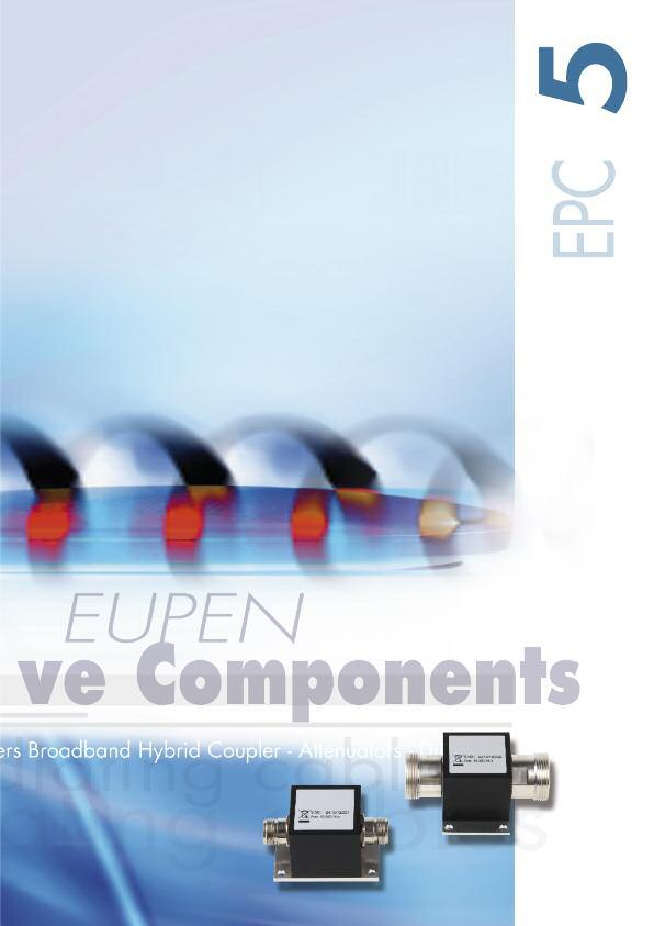
79
80 EPC DL - Dummy Loads FEATURES and BENEFITS Broadband Low VSWR Nm interface (7-16 on request) 1,2 or 10 W (other rating on request) SPECIFICATIONS 0-6 GHz 0-18 GHz 0-18 GHz N male N male N male Part Number EPC DL-T1 01 EPC DL-T2 01 EPC DL-T10 01 Frequency Range GHz 0-6 GHz 0-18 GHz 0-18 GHz Max. Input power W Impedance Nom. 50 Ω Nom. 50 Ω Nom. 50 Ω VSWR <1.15 / 6 GHz <1.15 / 4 GHz <1.15/ 4 GHz Temperature Range C -30 to to to +60 Dimensions (L x Ø) mm 34.5 x x x
 SPECIFICATIONS N female-female N male-female 7-16 DIN 7-16 DIN (*) female-female male-female (*) (*) Part number EPC DB-P 01 EPC DB-P 02 EPC DB-P 03 EPC DB-P 04 R1: 50-500")
81 EPC DB - DC Isolators (DC Block) FEATURES and BENEFITS High RF power rating High DC voltage rating Small size IP 65 rated Low Passive Intermodulation In-line protection against induced DC (inner/inner & outer/outer) SPECIFICATIONS N female-female N male-female 7-16 DIN 7-16 DIN (*) female-female male-female (*) (*) Part number EPC DB-P 01 EPC DB-P 02 EPC DB-P 03 EPC DB-P 04 R1: Frequency Range MHz R2: R3: R1: < 0.1 Insertion Loss db R2: < 0.2 R3: < 0.4 R1, R2: < 1.2 VSWR R3: < kv (Input centre to output centre conductor) Max. voltage DC 1.4 kv (Centre conductor to ground) 2 kv (Input ground to output ground) R1, R2: Max. 250 W Power handling R3: Max. 100 W Dimensions (L x W x H) mm 80 x 42 x 42 with N-connectors 100 x 42 x 42 with 7-16 DIN connectors (*) Consult us for MOQ 81

82 EPC SP - Splitters FEATURES and BENEFITS Low loss Good balance Wide bandwidth Isolated outputs Suitable for low power combining SPECIFICATIONS MHz MHz MHz N female N female N female Part Number EPC SP-P2 01 EPC SP-P2 02 EPC SP-P4 03 Frequency Range MHz Way VSWR < 1.2 < Max. Input power W Total loss db < MHz < 6.8 Impedance Nom. 50 Ω Nom. 50 Ω Nom. 50 Ω Temperature Range C -35 to to to +60 Dimensions (L x W x H) mm 212 x 61 x x152 x x 39 x 29 Weight approx. g

83 83

84
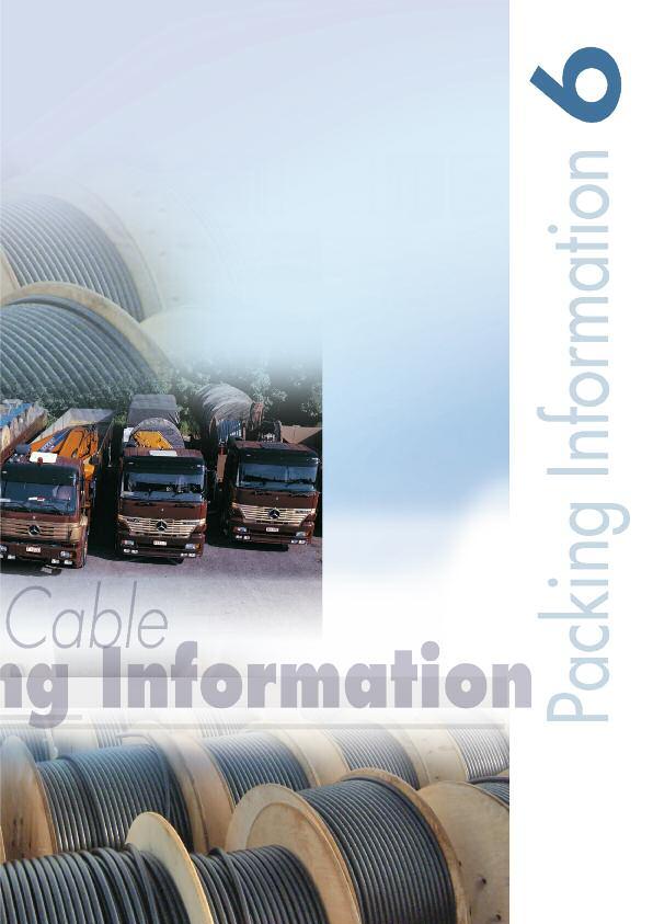
85
86 Cable Packing Information The coaxial cable will be supplied on wooden drums made of planed wooden boards or plywood. In order to protect the cable during transportation and storage, the drums will be battened with wooden boards nailed on the flanges. The drums are provided with a label containing cable information as cable type, cable length and production batch. The drums can be impregnated on request. The standard drum sizes used for the different cable types are shown in the table below. To calculate the total weight, add the approximate cable weight to the drum weight. d D A w W Cable length Outer dim. * Drum dim. D d Cable type Drum type m (ft) cm (in) cm (in) RMC, LSC, CMC 1/2 HE (1640) 100 (39.37) 46 (18.11) HE (3280) 120 (47.24) 40 (15.74) HE (4921) 120 (47.24) 40 (15.74) RMC 5/8 HE 14S 600 (1968) 140 (55.11) 80 (31.49) HE 14B 1100 (3600) 140 (55.11) 80 (31.49) HF 17S 1800 (5900) 170 (66.92) 90 (35.43) RMC, LSC 7/8 HE (1640) 140 (55.11) 80 (31.49) HF 17B 1000 (3280) 170 (66.92) 90 (35.43) HF (4921) 200 (78.74) 90 (35.43) RMC, LSC 1-1/4 HF 17S 500 (1640) 170 (66.92) 90 (35.43) HF (3280) 200 (78.74) 90 (35.43) RMC, LSC 1-5/8 HF 17B 350 (1148) 170 (66.92) 90 (35.43) HF (1968) 200 (78.74) 90 (35.43) F-RMC, F-LSC 7/8 HF 17B 500 (1640) 170 (66.92) 90 (35.43) HF (3280) 200 (78.74) 90 (35.43) F-RMC, F-LSC 1-1/4 HF 17B 500 (1640) 170 (66.92) 90 (35.43) HF (3280) 200 (78.74) 90 (35.43) F-RMC 1-5/8 HF (1968) 200 (78.74) 90 (35.43) * battened + 5 cm ** Cables with mica tape: see cable data sheet *** Depending on the humidity of the wood, drum weights can vary greatly! 86
 cm (in) cm (in) m 3 (ft 3 ) kg (Lb) kg/km (Lb) 70 (27.55) 64 (25.19) 6.5 (2.55) 0.69 (24.36) 16 / 46 (35 / 101) 240 (530) 54 (21.25) 50 (19.")
87 Drum label Outer width Inner width Shaft hole Drum freight Approx. Drum weight *** Approx. W w A Volume drum / battened drum Cable weight ** cm (in) cm (in) cm (in) m 3 (ft 3 ) kg (Lb) kg/km (Lb) 70 (27.55) 64 (25.19) 6.5 (2.55) 0.69 (24.36) 16 / 46 (35 / 101) 240 (530) 54 (21.25) 50 (19.68) 6.5 (2.55) 0.78 (27.54) 25 / 55 (55 / 121) 240 (530) 54 (21.25) 50 (19.68) 6.5 (2.55) 0.78 (27.54) 25 / 55 (55 / 121) 240 (530) 42 (16.53) 38.2 (15.03) 8 (3.14) 0.83 (29.31) 40 / 65 (88 / 143) 380 (840) 76 (29.92) 72.2 (28.42) 8 (3.14) 1.50 (52.97) 40 / 85 (88 / 187) 380 (840) 74 (29.13) 64.4 (25.35) 9 (3.54) 2.20 (77.69) 232 / 275 (511 / 605) 380 (840) 76 (29.92) 72 (28.34) 8 (3.14) 1.49 (52.61) 40 / 100 (88 / 220) 500 (1104) 104 (40.94) 98 (38.58) 9 (3.54) 3.03 (107.00) 380 / 470 (837 / 1034) 500 (1104) 116 (45.66) 104 (40.94) 9 (3.54) 4.75 (167.74) 440 / 555 (970 / 1221) 500 (1104) 70 (27.55) 64 (25.19) 9 (3.54) 2.20 (77.69) 232 / 275 (511 / 605) 895 (1980) 116 (45.66) 104 (40.94) 9 (3.54) 4.75 (167.74) 440 / 555 (970 / 1221) 895 (1980) 104 (40.94) 98 (38.58) 9 (3.54) 3.03 (107.00) 380 / 470 (837 / 1034) 925 (2040) 116 (45.66) 104 (40.94) 9 (3.54) 4.75 (167.74) 440 / 555 (970 / 1221) 925 (2040) 104 (40.94) 98 (38.58) 9 (3.54) 3.03 (107.00) 380 / 470 (837 / 1034) 750 (1675) 116 (45.66) 104 (40.94) 9 (3.54) 4.75 (167.74) 440 / 555 (970 / 1221) 750 (1675) 104 (40.94) 98 (38.58) 9 (3.54) 3.03 (107.00) 380 / 470 (837 / 1034) 1230 (2711) 116 (45.66) 104 (40.94) 9 (3.54) 4.75 (167.74) 440 / 555 (970 / 1221) 1230 (2711) 116 (45.66) 104 (40.94) 9 (3.54) 4.75 (167.74) 440 / 555 (970 / 1221) 1300 (2870) 87

88 Malmedyer Str EUPEN - BELGIUM Tel.: +32(0) Fax: +32(0) info@eupen.com ISO Certified Company 01/
EXCELLENT ELECTRICAL PERFORMANCES
 50OHMS CORRUGATED COPPER TUBE COAXIAL CABLE PRODUCT INTRODUCTION 2 Hansen's manufacturing of wide-scope 50ohms corrugated copper coaxial Cable is the fruitful result of the engineers' diligent research
S-Link. RF Cable Solution
 S-Link RF Cable Solution Netop supplys complete RF subsystem for site application with Rosenberger S-Link site solution package which include feeder cables, jumpers, connectors, surge arresters, grounding
EC 200 CHARACTERISTICS D A T A S H E E T. Kabelwerk EUPEN AG cable. M e c h a n i c a l c h a r a c t e r i s t i c s
 EC 200 EC200 - Rev. 3-23.06.11 Characteristic impedance 50 ± 2 Material copper wire Nominal capacity (pf/m) 80.5 Construction - Relative propagation velocity (%) 83 Diameter (mm) 1.05 Inductance (µh/m)
Since 1993 the company is ISO 9001 certified for all its products. The environmental policy of Kabelwerk EUPEN AG is also illustrated
 Edition 05 / 2015 The foundation of the cable factory Kabelwerk EUPEN AG as manufacturer of electrical cables goes back to the beginning of the 20th century. Today the company has a staff of 850 people
Including the. New LOW LOSS A Version. Edition 2007
 Including the New LOW LOSS A Version Edition 2007 The foundation of the cable factory KABELWERK EUPEN AG as manufacturer of electrical cables goes back to the beginning of this century. Today the company
Jumper cable. Feeder cable + connector. Cable clamp. Grounding kit
 Mobile Networks 1 Jumper cable Feeder cable + connector Cable clamp Grounding kit 2 28 Superflexible and Extraflexible Cables Draka superflexible RFF cables and extraflexible RFE cables offer the most
C400-UMUM-100. Jumper Assembly Sample Label. Product Classification. General Specifications. Return Loss/VSWR
 C400-UMUM-100 Product Classification Brand Product Series Product Type CNT Jumper with interface types UHF Male and UHF Male, 30.48 m CNT Braided cable assembly General Specifications Body Style, Connector
Coaxial Antenna. Properties and use. Reijo Kekäläinen ROK/
 Coaxial Antenna Properties and use Reijo Kekäläinen ROK/24.8.01 1 Need for Indoor Coverage Wireless communications are increasing rapidly Growth in the use of mobile services and products Growing use of
Connection technology for wireless communication systems
 Connection technology for wireless communication systems Rosenberger Rosenberger, founded in 1958, is a family owned company and ranks today among the top global manufacturers of high-frequency coaxial
AVA5-50FX. Product Classification. Standards And Qualifications. Construction Materials. Dimensions. Electrical Specifications
 AVA5RK-50FX, HELIAX Andrew Virtual Air Coaxial Cable, corrugated copper, 7/8 in, black, Non-halogenated, fire retardant polyolefin jacket B2ca-s1b,d1 Product Classification Brand Product Series Product
Edition January 2008
 Edition January 2008 New eupen corrugated aluminium cables INTRODUCTION EUPEN extends its cable product range with two specifically designed foam dielectric corrugated aluminum cables EA5-50 7/8 and EA7-50
New LOW LOSS A Version
 Including the New LOW LOSS A Version Edition 02-2010 The foundation of the cable factory KABELWERK EUPEN AG as manufacturer of electrical cables goes back to the beginning of the 20th century. Today the
Since 1993 the company is ISO 9001 certified for all its products.
 Edition 01 / 2012 The foundation of the cable factory KABELWERK EUPEN AG as manufacturer of electrical cables goes back to the beginning of the 20th century. Today the company has a staff of 950 people
C400-NMTM-1M. Jumper Assembly Sample Label. Product Classification. General Specifications. Return Loss/VSWR
 C400-NMTM-1M Product Classification Brand Product Series Product Type CNT-400 CNT Jumper with interface types N Male and TNC Male, 1m CNT CNT-400 Braided cable assembly General Specifications Body Style,
Coaxial Cables Coax Serie. HF Steckverbinder für Mobilfunk-Anwendungen. in Bulk Rings or on Cable Drums
 4.3-10 Coax Serie Coaxial Cables HF Steckverbinder für Mobilfunk-Anwendungen in Bulk Rings or on Cable Drums Coaxial Cables In addition to the wide range of coaxial connectors, Telegärtner offers suitable
C400-TMTM-30-X. Jumper Assembly Sample Label. Product Classification. General Specifications. Electrical Specifications
 C400-TMTM-30-X Product Classification Brand Product Series Product Type CNT-400-FR CNT Jumper with interface types TNC Male and TNC Male, 9.14 m CNT CNT-400 Braided cable assembly General Specifications
C195-SMQM-3M. Jumper Assembly Sample Label. Product Classification. General Specifications. Return Loss/VSWR
 C195-SMQM-3M Product Classification Brand Product Series Product Type CNT-195 CNT Jumper with interface types SMA Male and QMA Male, 3M CNT CNT-195 Braided cable assembly General Specifications Body Style,
C240-NFSM-3M. Jumper Assembly Sample Label. Product Classification. General Specifications. Return Loss/VSWR
 C240-NFSM-3M Product Classification Brand Product Series Product Type CNT Jumper with interface types N Female and SMA Male, 3m CNT Braided cable assembly General Specifications Body Style, Connector A
CABLES CABLES. Application note
 CABLES CABLES radiating TABLE OF CONTENTS INTRODUCTION 3 1. LONGITUDINAL ATTENUATION AND COUPLING LOSS 3 2. RADIATED AND COUPLED MODE CABLES 5 3. LINK BUDGET 7 3.1. RC insertion loss 8 3.2. RC Coupling
REQUEST FOR INFORMATION (RFI) RFI NO: /WJG
 RFI NO: /WJG") (RFI) RFI NO: 15-219/WJG WASHINGTON METROPOLITAN AREA TRANSIT AUTHORITY 600 FIFTH STREET, NW WASHINGTON DC 20001 ( WMATA OR AUTHORITY ) 1 ⅝ INCH RADIATING COAXIAL CABLE DATE: AUGUST 7, 2015 Contents Introduction...
(RFI) RFI NO: 15-219/WJG WASHINGTON METROPOLITAN AREA TRANSIT AUTHORITY 600 FIFTH STREET, NW WASHINGTON DC 20001 ( WMATA OR AUTHORITY ) 1 ⅝ INCH RADIATING COAXIAL CABLE DATE: AUGUST 7, 2015 Contents Introduction...
K20 & L120 LSZH Armoured F/FTP Cat6 Cables
 K20 & L120 LSZH Armoured F/FTP Cat6 Cables The cables are designed for high speed data transmissions, and are suitable for installations in cable trays or on hooks. RATP CAT6-K20 (for K20 cable) FRANCE
Speedflex. Halogen free coaxial cables.
 Speedflex Halogen free coaxial cables Speedflex is a completely halogen-free and environmentally-friendly alternative to standard RG coaxial cables. Speedflex Item Material Speedflex Speedflex Speedflex
ENGINEERING COMMITTEE Interface Practices Subcommittee AMERICAN NATIONAL STANDARD ANSI/SCTE
 ENGINEERING COMMITTEE Interface Practices Subcommittee AMERICAN NATIONAL STANDARD ANSI/SCTE 177 2012 Specification for Braided 75 Ω, Mini-Series Quad Shield Coaxial Cable for CMTS and SDI cables NOTICE
Kabelwerk Eupen AG 1
 Kabelwerk Eupen AG 1 The foundation of the cable factory KABELWERK EUPEN AG as manufacturer of electrical cables goes back to the beginning of last century. Today the company has a staff of 950 people
Data sheet MC GC1200 pro22 Cat.7A S/FTP 4P LSHF-FR, class Dca s2 d2
 Page 1/7 Illustrations Principle diagram See enlarged drawings at the end of document Product specification 10 GBit installation cable, simplex installation cable Cat.7A AWG 22 S/FTP with wires shielded
Through-beam ring sensors
 Throughbeam ring sensors Features Wide range of sizes: ring diameters of 10, 15 and 20 mm Metal housings Separate evaluation unit Connection by means of S8 connector Degree of protection IP 63 Adjustable
Chapter 12: Transmission Lines. EET-223: RF Communication Circuits Walter Lara
 Chapter 12: Transmission Lines EET-223: RF Communication Circuits Walter Lara Introduction A transmission line can be defined as the conductive connections between system elements that carry signal power.
Data sheet MC GC1200 pro22 Cat.7A S/FTP 2x4P LSHF-FR 1640 ft
 Page 1/7 Illustrations Principle diagram Product specification 10 GBit installation cable, duplex installation cable Cat.7A AWG 22 S/FTP with wires shielded in pairs 2x4 pairs (PiMF) pair shield: plastic
ZHONGTIAN TECHNOLOGIES CO., LTD
 ZHONGTIAN TECHNOLOGIES CO., LTD Contents Company profile...1 Quality certificates.. 2 Manufacture equipment 3 Products profile. 4 Radio Coaxial Cables 5 HHTAY-50-42 (1-5/8 ) HCTAY-50-32 (1-1/4 ) HCTAY-50-22
Kabelwerk Eupen AG 1
 Kabelwerk Eupen AG 1 The foundation of the cable factory KABELWERK EUPEN AG as manufacturer of electrical cables goes back to the beginning of this century. Today the company has a staff of 950 people
Frame through-beam sensors
 Frame through-beam sensors Features Wide range of sizes: passage sizes from 25 x 23 mm to 300 x 397.5 mm Metal housings Integrated evaluation unit Connection by means of connector Degree of protection
Consolidation and development of the CERN Leaky Feeder infrastructure
 Consolidation and development of the CERN Leaky Feeder infrastructure F. Chapron IT/CS/CS Agenda What is the use of the leaky feeder (LF) cable at CERN? What is a LF cable? What is the issue? Risks assessment
e-guide to RF Signals UNLICENSED & ISM BANDS LAND MOBILE & PUBLIC SAFETY CELLULAR AERONAUTICAL RADIO & TELEVISION BROADCAST WEATHER RADAR
 e-guide to RF Signals UNLICENSED & ISM BANDS LAND MOBILE & PUBLIC SAFETY CELLULAR AERONAUTICAL RADIO & TELEVISION BROADCAST WEATHER RADAR A Guide to The Radio Spectrum Unlicensed and ISM Bands Unlicensed
Keysight Technologies N9398C/F/G and N9399C/F DC Block. Technical Overview
 Keysight Technologies N9398C/F/G and N9399C/F DC Block Technical Overview Introduction Key Features Maximize your operating range - 26.5, 50 or 67 GHz Improve calibration accuracy with exceptional return
LMR LMR Ohm Flexible Low Loss Coaxial Cable TIMES MICROWAVE SYSTEMS
 LMR-200-75 LMR -200-75 Ohm Flexible Low Loss Coaxial Cable Ideal for Satellite Applications Video Applications-CCTV, CATV, baseband or broadband In-Building Feeder Runs Any 75 ohm Wireless Application
Labs. Introduction. Specialty Family
 INC. Labs Introduction Specialty Family Features K-Jumper: Affordable, High Performance Interconnect up to 35 GHz Space-Flex : Semi-Rigid and Flexible Cable Assemblies for S-Level Space T-Flex : Flexible
COAX 101. Author: Rob Wessels. Vice President of Engineering
 COAX 101 Author: Rob Wessels Vice President of Engineering Structured cable systems have very thorough standards for fiber optic and twisted pair installations. The cabling components and installed systems
Keysight Technologies Using a Network and Impedance Analyzer to Evaluate MHz RFID Tags and Readers/Writers
 Keysight Technologies Using a Network and Impedance Analyzer to Evaluate 13.56 MHz RFID Tags and Readers/Writers Application Note L C R f 0 = 2 1 π L C Introduction RFIDs, also called non-contact IC cards
For information transmission at dry and moist production sites, in and under plaster, outdoors for fixed installation.
 Telecommunication and fire alarm cables For information transmission at dry and moist production sites, in and under plaster, outdoors for fixed installation. J-YY Bd 14 J-YY BMK 15 J-Y(St)Y Lg 16 J-Y(St)Y
EZ-200-NMH-D ok by tech Svcs
 EZ-200-NMH-D ok by tech Svcs EZ-200-NMH-D ok by tech Svcs LMR LMR-200 600 TIMES MICROWAVE SYSTEMS LMR -200 Flexible Low Loss Communications Coax Ideal for Jumper Assemblies in Wireless Communications Systems
LMR-240. LMR -240 Flexible Low Loss Communications Coax TIMES MICROWAVE SYSTEMS
 LMR-240 LMR -240 Flexible Low Loss Communications Coax Ideal for Jumper Assemblies in Wireless Communications Systems Short Antenna Feeder runs (e.g. WLL, GPS, LMR, Mobile Antennas) Any application (e.g.
CISCO ONS /100-GHZ INTERLEAVER/DE-INTERLEAVER FOR THE CISCO ONS MULTISERVICE TRANSPORT PLATFORM
 DATA SHEET CISCO ONS 15216 50/100-GHZ INTERLEAVER/DE-INTERLEAVER FOR THE CISCO ONS 15454 MULTISERVICE TRANSPORT PLATFORM The Cisco ONS 15216 50/100-GHz Interleaver/De-interleaver is an advanced 50/100-GHz
RECOMMENDATION ITU-R M (Question ITU-R 36/8)
") Rec. ITU-R M.1075 1 RECOMMENDATION ITU-R M.1075 LEAKY FEEDER SYSTEMS IN THE LAND MOBILE SERVICES (Question ITU-R 36/8) (1994) Rec. ITU-R M.1075 The ITU Radiocommunication Assembly, considering a) that
Rec. ITU-R M.1075 1 RECOMMENDATION ITU-R M.1075 LEAKY FEEDER SYSTEMS IN THE LAND MOBILE SERVICES (Question ITU-R 36/8) (1994) Rec. ITU-R M.1075 The ITU Radiocommunication Assembly, considering a) that
Sure Cross Radio Certifications
 Sure Cross Radio Certifications Banner's Sure Cross product line is certified by the FCC, European Union, and many other countries for operation within specific radio frequencies. FCC Certification, 900MHz
Basics of Using the NetTek YBA250
 Basics of Using the NetTek YBA250 Properly Test Antennae and Locate Faults Use the NetTek YBA250 for determining the health of base station antenna systems, identifying transmission line trouble, and easily
stripax The professional stripping tool
 stripax The professional stripping tool stripax the original: developed from experience Weidmüller is the world s leading manufacturer of solutions for electrical connectivity, transmission, conditioning
H155A02. Product Description. Product Specifications. Technical Specifications. Application. Bend Radius. CCB-Sub-Crush Resistance.
 H155A02 Part Number: H155A02 COAX RF H155 FRNC Product Description COAX RF H155 FRNC Product Specifications Application Application 1: Application 2: 50 Ohm low loss coaxial transmission cable designed
BenchTop Extraction Arms with unbeatable flexibility
 BenchTop Extraction Arms with unbeatable flexibility A new generation of BenchTop extraction arms with unbeatable flexibility Nederman introduces a new generation of BenchTop arms the FX, FX and FX. These
ZHONGTIAN TECHNOLOGIES CO., LTD
 ZHONGTIAN TECHNOLOGIES CO., LTD Contents Company profile...1 Quality certificates.. 2 Manufacture equipment 3 Products profile. 4 Radio Frequency Coaxial Cables 5 HHTAY-50-42 (1-5/8 ) HCTAY-50-32 (1-1/4
BenchTop Extraction Arms with unbeatable flexibility
 BenchTop Extraction Arms with unbeatable flexibility A new generation of BenchTop extraction arms with unbeatable flexibility Nederman introduces a new generation of BenchTop arms the FX, FX and FX. These
Cisco ONS Metropolitan Dense Wavelength Division Multiplexing 100-GHz FlexLayer Filter Solution
 Data Sheet Cisco ONS 15216 Metropolitan Dense Wavelength Division Multiplexing 100-GHz FlexLayer Filter Solution The Cisco ONS 15216 Metropolitan Dense Wavelength-Division Multiplexing (DWDM) FlexLayer
Keysight Technologies Differences in Application Between Power Dividers and Power Splitters. Application Note
 Keysight Technologies Differences in Application Between Dividers and Splitters Application Note 02 Keysight Differences in Application Between Dividers and Splitters Application Note Introduction dividers
Rail & Transit Solutions
 Rail & Transit Solutions Times LMR Coaxial Cable & Connectors Times Protect RF Lightning Protection Introduction Index: Capability Qualification LMR FR LMR UFFR LMR 75FR Connectors & Tools Lightning Protector
Keysight Technologies N9398C/F/G and N9399C/F DC Block. Technical Overview
 Keysight Technologies N9398C/F/G and N9399C/F DC Block Technical Overview Introduction Key Features Maximize your operating range - 26.5, 50 or 67 GHz Improve calibration accuracy with exceptional return
To offer our customer the highest quality Broadband products at a competitive price with efficient Delivery and Inventory.
 ALANTEK COMMUNICATIONS Founded in 1998 and headquartered in the USA, is a professional manufacturer of Broadband Coaxial Cables & Accessories. Its strength th in engineering and manufacturing is reflected
ATBTK-MF-4G. Product Classification. Mechanical Specifications. Dimensions. Regulatory Compliance/Certifications.
 ATBTK-MF-4G Bias Tee Kit, AISG Compatible 698-2700 MHz Product Classification Product Type RET bias tee Mechanical Specifications Antenna Interface 7-16 DIN Female BTS Interface 7-16 DIN Male Dimensions
Agilent N8973A, N8974A, N8975A NFA Series Noise Figure Analyzers. Data Sheet
 Agilent N8973A, N8974A, N8975A NFA Series Noise Figure Analyzers Data Sheet Specifications Specifications are only valid for the stated operating frequency, and apply over 0 C to +55 C unless otherwise
N Male Connector Clamp/Solder Attachment for PE-C500, LMR-500
 N Male Connector Clamp/Solder Attachment for PE-C500, LMR-500 RF Connectors Technical Data Sheet PE44046 Configuration N Male Connector MIL-STD-348A 50 Ohms Features Gold Plated Brass Contact Applications
Keysight Technologies 8490G Coaxial Attenuators. Technical Overview
 Keysight Technologies 8490G Coaxial Attenuators Technical Overview Introduction Key Specifications Maximize your operating frequency range for DC to 67 GHz application Minimize your measurement uncertainty
Keysight Technologies RF & Microwave Attenuators. Performance you can count on
 Keysight Technologies RF & Microwave Attenuators Performance you can count on Key Features High reliability and exceptional repeatability reduce downtime Excellent RF specifications optimize test system
Keysight Technologies Waveguide Power Sensors. Data Sheet
 Keysight Technologies Waveguide Power Sensors Data Sheet 02 Keysight Waveguide Power Sensors - Data Sheet Make accurate and reliable measurements in the 50 to 110 GHz frequency range with Keysight s family
Data sheet MC GC1000 pro23 Cat.7 S/FTP 4P LSHF-FR 1640 ft
 Page 1/6 MC GC0 pro23 Cat.7 S/FTP 4P LSHF-FR 1640 ft 18427034141 Illustrations Principle diagram Product specification 10 GBit installation cable, simplex installation cable Cat.7 AWG 23 S/FTP with wires
Keysight Technologies, Inc. UWB Antenna Measurements with the 20 GHz E5071C ENA Network Analyzer. Application Note
 Keysight Technologies, Inc. UWB Antenna Measurements with the 20 GHz E5071C ENA Network Analyzer Application Note Introduction Ultra-wideband (UWB) is a rapidly growing technology that is used to transmit
Site Solutions Coaxial Feeder Cables 50 Ω High Performance Transmission Line Solutions
 Site Solutions Coaxial Feeder Cables 50 Ω High Performance Transmission Line Solutions Intro Rosenberger Group Rosenberger is one of the worldwide leading suppliers of controlled impedance and optical
Coaxial Cables. Coaxial Cables. & Addison.
 Coaxial Cables Coaxial Cables & Addison www.caledonian-cables.co.uk www.caledonian-cables.net www.addison-cables.net www.addison-cables.com 1 Company Profile Coaxial Cabless. established in 1978.offers
BGN. All Metal Variable Area Flowmeter and Counter. for liquids and gases
 All Metal Variable Area Flowmeter and Counter for liquids and gases monitoring analysing BGN Measuring range: 0.5-5.0... 13000-130000 l/h water 0.015-0.15... 240-2400 m³/h air (20 C, 1.013 bar) Accuracy
This document is a preview generated by EVS
 TECHNICAL REPORT CLC/TR 50427 RAPPORT TECHNIQUE TECHNISCHER BERICHT December 2004 ICS 13.230; 33.060.20 English version Assessment of inadvertent ignition of flammable atmospheres by radio-frequency radiation
Making a S11 and S21 Measurement Using the Agilent N9340A
 Making a S11 and S21 Measurement Using the Agilent N9340A Application Note Introduction Spectrum characteristics are important in wireless communication system maintenance. Network and spectrum analyzers
PO01275C Tabor East Neighborhood Meeting. Monday, April 20, :30 PM 8:30 PM
 PO01275C Tabor East Neighborhood Meeting Monday, April 20, 2015 6:30 PM 8:30 PM 1 Opening Remarks, Introductions, Explanation of Agenda and Procedure Lenny Borer Moderator 2 Portland Office for Community
 Agilent PN 4395-1 Agilent 4395A Network/Spectrum/ Impedance Analyzer Silicon Investigations Repair Information - Contact Us 920-955-3693 www.siliconinvestigations.com ADSL Copper Loop Measurements Product
Don t Let EMI/EMC Compliance Certification Slow You Down TUTORIAL
 Don t Let EMI/EMC Compliance Certification Slow You Down TUTORIAL TUTORIAL Uncover Problems Early with Pre-compliance Testing EMI regulations are in place throughout the world to provide improved reliability
 Using a Network and Impedance Analyzer to Evaluate 13.56 MHz RFID Tags and Readers/Writers Silicon Investigations Repair Information - Contact Us 920-955-3693 www.siliconinvestigations.com Application
Keysight Technologies N6850A Broadband Omnidirectional Antenna. Data Sheet
 Keysight Technologies N6850A Broadband Omnidirectional Antenna Data Sheet 02 Keysight N6850A Broadband Omnidirectional Antenna - Data Sheet Industries and Applications Spectrum monitoring and signal location,
UWB Antenna Measurements with the 20 GHz E5071C ENA Network Analyzer
 UWB Antenna Measurements with the 20 GHz E5071C ENA Network Analyzer Application Note Minimize cost of test with the 20 GHz ENA s high performance and fast measurement speed Quickly leverage your current
Keysight E5063A ENA Series Network Analyzer
 Keysight E5063A ENA Series Network Analyzer 100 khz to 500 M/1.5 G/3 G/4.5 G/6.5 G/8.5 G/14 G/18 GHz Configuration Guide 02 Keysight E5063A ENA Series Network Analyzer - Configuration Guide Ordering Guide
Product quality is the life of CenRF CenRF Communications Limited
 Product quality is the life of CenRF Contents Company Introduction Professional Team High Quality Products Product Application Company Introduction Hangzhou Shengtong Technology Co., Ltd. (), is a professional
Medium Voltage Power Cables
 N2XSY 6/0, /20, /30 NA2XSY 6/0, /20, /30 N2XS2Y 6/0, /20, /30 NA2XS2Y 6/0, /20, /30 N2XS(F)2Y 6/0, /20, /30 NA2XS(F)2Y 6/0, /20, /30 N2XSEY 3 x 6/0 Medium Voltage Power Cables Photo: HELUKABEL Q 47 Medium
SBCA Industry Standards Subcommittee. Specification for 75 Ω Flexible RF Coaxial Drop Cable for Direct Broadcast Satellite (DBS) Installations
 Installations") SBCA Industry Standards Subcommittee Document: SBCA Series 6 Recommended Practices Date of Issue: Specification for 75 Ω Flexible RF Coaxial Drop Cable for Direct Broadcast Satellite (DBS) Installations
SBCA Industry Standards Subcommittee Document: SBCA Series 6 Recommended Practices Date of Issue: Specification for 75 Ω Flexible RF Coaxial Drop Cable for Direct Broadcast Satellite (DBS) Installations
NGR. Guided Wave Radar Level Transmitter
 Guided Wave Radar Level Transmitter measuring monitoring analyzing NGR For Liquids Operates Independent of Density, Temperature, Pressure, Humidity, and Conductivity Standard Measuring Length: 6. Ft (Longer
The compact test- disconnect terminal interface system for protection and secondary technology
 POCON POWER Connector The compact test- disconnect terminal interface system for protection and secondary technology POCON the compact test-disconnect terminal interface system Safe control and testing
Ship and Offhsore. Approved cables for ship- and offshoreindustry
 Ship and Offhsore Approved cables for ship- and offshoreindustry NEK Kabel AS - Norway. (NEK Sealine Marine products) tel. +47 67 91 21 80 - Firmapost@nek-kabel.no 1 OVER 100 YEARS OF EXPERIENCE 1913-2013
NETWORK CONNECTIVITY SYSTEMS
 NETWORK CONNECTIVITY SYSTEMS Installation Cable KS-STP Category 7 Installation Cable Certificates 10GBaseT FTP Category 6 Installation Cable UTP Category 6 Installation Cable UTP Category 5E Installation
50 Ohm COAXES EUROPE. Quality in. 50 Ohm COAXES. WIRELESS Low Loss RG/U MIL-C-17
 50 Ohm COAXES 179 - EUROPE Quality in 50 Ohm COAXES WIRELESS Low Loss RG/U MIL-C-17 Coaxes coded WL are 50 Ohm flexible cables manufactured by Italiana Conduttori and they perform and combine a low loss
Detailed Specifications & Technical Data
 Description: Series 11, 14 AWG solid.064" bare copper-covered steel conductor, gas-injected foam polyethylene insulation, Duobond IV quad shield (60% and 40% coverage), PVC jacket Physical Characteristics
COAXIAL CABLE and FITTINGS SUMMARY RF CABLE ASSEMBLIES
 SUMMARY RF CABLE ASSEMBLIES Custom Cable Assemblies Standard Cable Sets CABLE FITTINGS 7/8" Flexible Foam Dielectric, 50 Ohm Hoisting Stocking Grips 1/2" Flexible Foam Dielectric, 50 Ohm Bird-Proof Stainless
You need the best connection!
 Passion Passion in high in high frequency Passion Passion in high in high frequency Coaxial, connectors adaptors for radio communications Your dealer SSB-Electronic GmbH Ostenfeldmark 59557 Lippstadt/Germany
Keysight Technologies 85072A 10-GHz Split Cylinder Resonator. Technical Overview
 Keysight Technologies 85072A 10-GHz Split Cylinder Resonator Technical Overview 02 Keysight 85072A 10-GHz Split Cylinder Resonator - Technical Overview Part of the complete turn-key solution for the IPC
Labs. Introduction. Specialty Family
 INC. Labs Introduction Specialty Family Features K-Jumper: Affordable, High Performance Interconnect up to 35 GHz Sta-Put: Zero Loading Test Cable Space-Flex : Semi-Rigid and Flexible Cable Assemblies
Tru products are now under the Tru-Win brand from Winchester Interconnect.
 TRUflex PWR Series TRUflex PWR Series cable assemblies offers an extensive line of flexible RF cable assembly and connector solutions for applications that require RF high power/voltage capability as well
Information technology. Generic cabling systems, General requirements
 KRAMER WELL CONNECTED WITH KRAMER BCLS-33OR-5 Al-Mylar Conductor CAT6A F/UTP LSZH Cable Drain Wire Kramer s BCLS-33OR is a high performance CAT6A F/UTP cable designed for IT, LAN and Ethernet installations.
STAINLESS STEEL STAINLESS STEEL MANUFACTURING STAINLESS STEEL TRADING BRIGHT BARS WIRES PRECISION COMPONENTS
 STAINLESS STEEL BRIGHT BARS WIRES PRECISION COMPONENTS BHANSALI is diversified business group with interests in Stainless Steel, Textiles and ABS Plastics. Under the dynamic leadership of Mr. Pukhraj Bhansali
MULTIFLEX The flexible alternative to SEMI-RIGID
 MULTIFLEX The flexible alternative to SEMI-RIGID Content Product description................................................................. 65 Features and benefits...............................................................
Isolation Addresses Common Sources of Differential Measurement Error
 By Tom Neville A typical measurement system includes an oscilloscope and an oscilloscope probe that provides the connection between the device under test (DUT) and the oscilloscope. Probe selection is
WOODWORKING TECHNOLOGY IN EUROPE: HIGHLIGHTS European Federation of Woodworking Technology Manufacturers
 European Federation of Woodworking Technology Manufacturers ADVANCED ECONOMIES - GDP % GROWTH RATE 2017 8,0 7,0 6,0 5,0 4,0 3,0 2,0 1,0 0,0 Ireland Malta Slovenia Estonia Latvia Czech Republic Cyprus
Passive High Voltage Probes P5100A-TPP0850-P5122-P5150-P6015A Datasheet
 Passive High Voltage Probes P5100A-TPP0850-P5122-P5150-P6015A Datasheet P5150 DC to 500 MHz 2500 V Peak, 1000 V RMS CAT II 50 X Floatable up to 600 V RMS CAT II or 300 V RMS CAT III For TPS2000 and THS3000
AEE. Canada. Australia
 DMARCA DE CONFORMIDA CORDS & ELECTRICAL UNIVERSAL POWER JUMPER CORD INTERNATIONAL AGENCIES APPROVED 302 POWER JUMPER CORD APPLICATIONS: To Connect Accessories and Peripherals to Computers and Electronic
Measuring Vgs on Wide Bandgap Semiconductors APPLICATION NOTE
 Measuring Vgs on Wide Bandgap Semiconductors This application note focuses on accurate high-side V GS measurements using the IsoVu measurement system. The measurements described in this application note
Tru products are now under the Tru-Win brand from Winchester Interconnect.
 TRU MEIA Series Tru-Win MEIA offers the latest innovation in high power connector design. The MEIA interface provides equivalent kw power handling compared to similar EIA connector line sizes but provides
SL1200 (GeoHelix P2) Passive GPS Antenna Product Specifi cation
 Passive GPS Antenna Product Specifi cation") SL1200 (GeoHelix P2) Passive GPS Antenna Product Specifi cation Product Description Built on patented PowerHelix fi ltering antenna technology, the SL1200 GPS antenna provides high performance in diffi
SL1200 (GeoHelix P2) Passive GPS Antenna Product Specifi cation Product Description Built on patented PowerHelix fi ltering antenna technology, the SL1200 GPS antenna provides high performance in diffi
ACR (Attenuation to Crosstalk Ratio) ACR-F. Alien Crosstalk. Attenuation (signal attenuation, conductor attenuation)
 ACR-F. Alien Crosstalk. Attenuation (signal attenuation, conductor attenuation)") ACR (Attenuation to Crosstalk Ratio) The distance between the wanted signal and the interfering signal (ACR) is an important factor for the transmission quality. To ensure a faultless transmission, the
ACR (Attenuation to Crosstalk Ratio) The distance between the wanted signal and the interfering signal (ACR) is an important factor for the transmission quality. To ensure a faultless transmission, the