$MPTFE -PPQ 4UFQQJOH 4ZTUFN.JOJBUVSJ[FE $PNQBDU 4J[F $MPTFE -PPQ 4ZTUFN /P (BJO 5VOJOH /P )VOUJOH )JHI 3FTPMVUJPO 'BTU 3FTQPOTF
|
|
|
- Alyson Hood
- 5 years ago
- Views:
Transcription


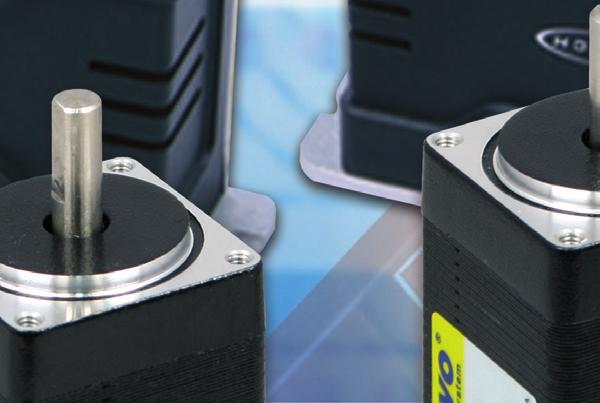
1 $MPTFE -PPQ 4UFQQJOH 4ZTUFN.JOJBUVSJ[FE $PNQBDU 4J[F $MPTFE -PPQ 4ZTUFN /P (BJO 5VOJOH /P )VOUJOH )JHI 3FTPMVUJPO 'BTU 3FTQPOTF ú ú ú ú ú ú


2 2
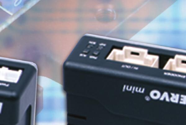
3 2 No Gain Tuning Conventional servo systems, to ensure machine performance, smoothness, positional error and low servo noise, require the adjustment of its servo s gains as an initial crucial step. Even systems that employ auto-tuning require manual tweaking after the system is installed, especially if more that one axis are interdependent. Ezi-SERVO employs the best characteristics of stepper and closed loop motion controls and algorithms to eliminate the need of tedious gain tuning required for conventional closed loop servo systems. This means that Ezi-SERVO is optimized for the application and ready to work right out of the box! The Ezi-SERVO system employs the unique characteristics of the closed loop stepping motor control, eliminating these cumbersome steps and giving the engineer a high performance servo system without wasting setup time. Ezi-SERVO is especially well suited for low stiffness loads (for example, a belt and pulley system) that sometime require conventional servo systems to inertia match with the added expense and bulk of a gearbox. Ezi-SERVO also performs exceptionally, even under heavy loads and high speeds! 3 No Hunting Traditional servo motor drives overshoot their position and try to correct by overshooting the opposite direction, especially in high gain applications. This is called null hunt and is especially prevalent in systems that the break away or static friction is significantly higher than the running friction. The cure is lowering the gain, which affects accuracy or using Ezi-SERVO Motion Control System! Ezi-SERVO utilizes the unique characteristics of stepping motors and locks itself into the desired target position, eliminating Null Hunt. This feature is especially useful in applications such as nanotech manufacturing, semiconductor fabrication, vision systems and ink jet printing in which system oscillation and vibration could be a problem. 1 Closed Loop System Ezi-SERVO is an innovative closed loop stepping motor and controller that utilizes a high-resolution motor mounted encoder to constantly monitor the motor shaft position. The encoder feedback feature allows the Ezi-SERVO to update the current motor shaft position information every 25 micro seconds. This allows the Ezi-SERVO drive to compensate for the loss of position, ensuring accurate positioning. For example, due to a sudden load change, a conventional stepper motor and drive could lose a step creating a positioning error and a great deal of cost to the end user! Complete stop Hunting 3
4 4 Smooth and Accurate 7 High Torque Ezi-SERVO is a high-precision servo drive, using a highresolution encoder with 32,000 pulses/revolution. Unlike a conventional Microstep drive, the on-board high performance DSP (Digital Signal Processor) performs vector control and filtering, producing a smooth rotational control with minimum ripples. Compared with common step motors and drives, Ezi-SERVO motion control systems can maintain a high torque state over relatively long period of time. This means that Ezi-SERVO continuously operates without loss of position under 100% of the load. Unlike conventional Microstep drives, Ezi-SERVO exploits continuous high-torque operation during high-speed motion due to its innovative optimum current phase control. 5 Fast Response Similar to conventional stepping motors, Ezi-SERVO instantly synchronizes with command pulses providing fast positional response. Ezi-SERVO is the optimum choice when zerospeed stability and rapid motions within a short distance are required. Traditional servo motor systems have a natural delay between the commanding input signals and the resultant motion because of the constant monitoring of the current position, necessitating in a waiting time until it settles, called settling time. 8 High Speed The Ezi-SERVO functions well at high speed without the loss of Synchronism or positioning error. Ezi-SERVO s ability of continuous monitoring of current position enables the stepping motor to generate high-torque, even under a 100% load condition. 4 6 High Resolution The unit of the position command can be divided precisely. (Max. 32,000 pulses/revolution)
5 Part Numbering Ezi-SERVO-MI-20S-A- Closed Loop Stepping System Name Motor Flange Size 20 : 20mm 25 : 25mm 28 : 28mm 35 : 35mm 42 : 42mm Motor Length S : Single M : Middle L : Large XL: Extra Large Encoder Resolution A : 10,000/Rev. B : 20,000/Rev. C : 32,000/Rev. D : 16,000/Rev. F : 4,000/Rev. User Code Combination List of Ezi-SERVO MINI Unit Part Number Motor Model Number Drive Model Number Ezi-SERVO-MI-20M-F EzM-20M-F EzS-PD-MI-20M-F Ezi-SERVO-MI-20L-F EzM-20L-F EzS-PD-MI-20L-F Ezi-SERVO-MI-25S-F-L EzM-25S-F-L EzS-PD-MI-25S-F Ezi-SERVO-MI-25M-F-L EzM-25M-F-L EzS-PD-MI-25M-F Ezi-SERVO-MI-25L-F-L EzM-25L-F-L EzS-PD-MI-25L-F Ezi-SERVO-MI-28S-D EzM-28S-D EzS-PD-MI-28S-D Ezi-SERVO-MI-28M-D EzM-28M-D EzS-PD-MI-28M-D Ezi-SERVO-MI-28L-D EzM-28L-D EzS-PD-MI-28L-D Ezi-SERVO-MI-35S-D EzM-35S-D EzS-PD-MI-35S-D Ezi-SERVO-MI-35M-D EzM-35M-D EzS-PD-MI-35M-D Ezi-SERVO-MI-35L-D EzM-35L-D EzS-PD-MI-35L-D Ezi-SERVO-MI-35XL-D EzM-35XL-D EzS-PD-MI-35XL-D Ezi-SERVO-MI-42S-A EzM-42S-A EzS-PD-MI-42S-A Ezi-SERVO-MI-42S-B EzM-42S-B EzS-PD-MI-42S-B Ezi-SERVO-MI-42S-C EzM-42S-C EzS-PD-MI-42S-C Ezi-SERVO-MI-42M-A EzM-42M-A EzS-PD-MI-42M-A Ezi-SERVO-MI-42M-B EzM-42M-B EzS-PD-MI-42M-B Ezi-SERVO-MI-42M-C EzM-42M-C EzS-PD-MI-42M-C Ezi-SERVO-MI-42L-A EzM-42L-A EzS-PD-MI-42L-A Ezi-SERVO-MI-42L-B EzM-42L-B EzS-PD-MI-42L-B Ezi-SERVO-MI-42L-C EzM-42L-C EzS-PD-MI-42L-C Ezi-SERVO-MI-42XL-A EzM-42XL-A EzS-PD-MI-42XL-A Ezi-SERVO-MI-42XL-B EzM-42XL-B EzS-PD-MI-42XL-B Ezi-SERVO-MI-42XL-C EzM-42XL-C EzS-PD-MI-42XL-C Advantages over Open-loop Control Stepping Drive 1. Reliable positioning without loss of synchronism. 2. Holding stable position and automatically recovering to the original position even after experiencing positioning error due to external forces, such as mechanical vibration or vertical positional holding. 3. Ezi-SERVO utilizes 100% of the full range of rated motor torque, contrary to a conventional open-loop stepping driver that can use up to 50% of the rated motor torque due to the loss of synchronism. 4. Capability to operate at high speed due to load-dependant current control, open-loop stepper drivers use a constant current control at all speed ranges without considering load variations. 5 Advantages over Servo Motor Controller 1. No gain tuning (Automatic adjustment of gain in response to a load change.) 2. Maintains the stable holding position without oscillation after completing positioning. 3. Fast positioning due to the independent control by on-board DSP. 4. Continuous operation during rapid short-stroke movement due to instantaneous positioning.
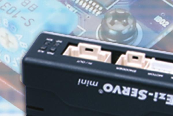
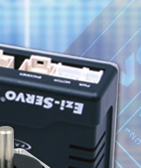
6 Specifications Motor Model EzM-20 series EzM-25 series EzM-28 series EzM-35 series EzM-42 series Driver Model Input Voltage Control Method Current Consumption Operating Condition Function I/O Signal Ambient Temperature Humidity Vib. Resist. 0.5G Rotation Speed Resolution(P/R) Max. Input Pulse Frequency Protection Functions LED Display EzS-PD-MI-20 series 24VDC±10% EzS-PD-MI-25 series Closed loop control with 32bit DSP Max 500mA (Except motor current) In Use : 0~50 In Storage : -20~70 In Use : 35~85% (Non-Condensing) In Storage : 10~90% (Non-Condensing) 0~3,000rpm EzS-PD-MI-28 series EzS-PD-MI-35 series 4,000/Rev. Encoder model : 500 1,000 1,600 2,000 3,600 5,000 6,400 7,200 10,000 4,000 10,000/Rev. Encoder model : 500 1,000 1,600 2,000 3,600 5,000 6,400 7,200 10,000 16,000/Rev. Encoder model : 500 1,000 1,600 2,000 3,600 5,000 6,400 7,200 10,000 16,000 20,000/Rev. Encoder model : 500 1,000 1,600 2,000 3,600 5,000 6,400 7,200 10,000 20,000 32,000/Rev. Encoder model : 500 1,000 1,600 2,000 3,600 5,000 6,400 7,200 10,000 32,000 (Selectable with DIP switch) 500KHz (Duty 50%) EzS-PD-MI-42 series Over Current Error, Over Speed Error, Position tracking Error, Over load Error, Over temperature Error, Over regenerated voltage Error, Motor connect Error, Encoder connect Error, Motor voltage Error, In-Position Error, System Error, ROM Error, Position overflow Error Power status, In-Position status, Servo On status, Alarm status, In-Position Selection 0~F (Selectable with DIP switch) Position Gain Selection 0~F (Selectable with DIP switch) RESOLUTION D P X X (55) Pulse Input Method 1-Pulse / 2-Pulse (Selectable with DIP switch) Rotational Direction CW / CCW (Selectable with DIP switch) Speed/Position Control Command Pulse train input Input Signals Position command pulse, Servo On/Off, Alarm reset (Photocoupler input) Output Signals In-Position, Alarm (Photocoupler output) Encoder signal (A+, A-, B+, B-, Z+, Z-, 26C31 of Equivalent) (Line Driver output) Drive Dimension (mm) mini IN POSITION PI GAIN 69.8 PWR MOTOR ENCODER IN/OUT PWR ALM INP SON 21.5
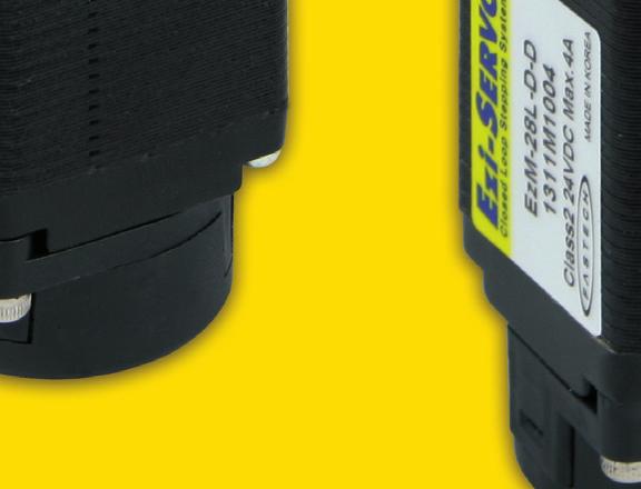
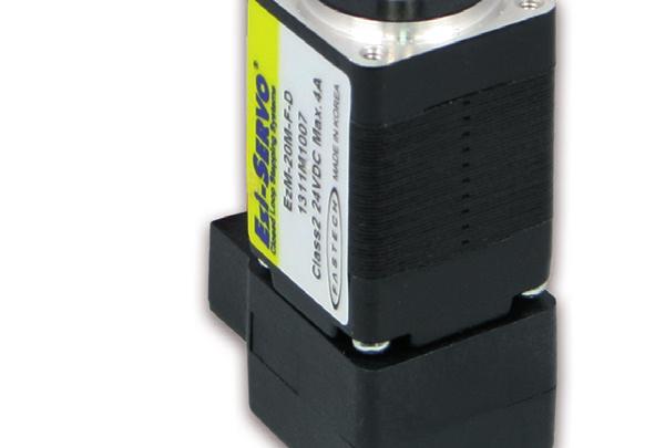
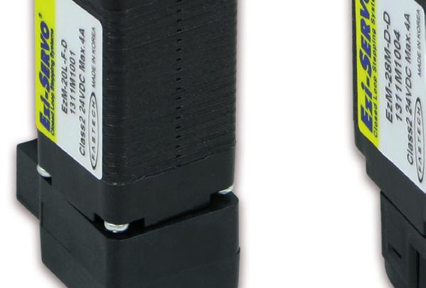
7 Motor Specifications 20 M O D E L UNIT EzM-20M-F EzM-20L-F DRIVE METHOD ---- BI-POLAR BI-POLAR NUMBER OF PHASES VOLTAGE VDC CURRENT per PHASE A RESISTANCE per PHASE Ohm INDUCTANCE per PHASE mh HOLDING TORQUE N m ROTOR INERTIA g cm WEIGHTS g LENGTH (L) mm ALLOWABLE OVERHUNG LOAD 3mm N (DISTANCE FROM END OF SHAFT) 8mm ALLOWABLE THRUST LOAD N Lower than motor weight INSULATION RESISTANCE MOhm 100min. (at 500VDC) INSULATION CLASS ---- CLASS B (130 ) OPERATING TEMPERATURE 0 to 55 Motor Dimension [mm] and Torque Characteristics 7 Measured Condition Motor Voltage = 24VDC Motor Current = Rated Current(Refer to Motor Specification) Drive = Ezi-SERVO MINI
8 Low Vibration 25 Motor Specifications M O D E L UNIT EzM-25S-F-L EzM-25M-F-L EzM-25L-F-L DRIVE METHOD ---- BI-POLAR BI-POLAR BI-POLAR NUMBER OF PHASES VOLTAGE VDC CURRENT per PHASE A RESISTANCE per PHASE Ohm INDUCTANCE per PHASE mh HOLDING TORQUE N m ROTOR INERTIA g cm WEIGHTS g LENGTH (L) mm ALLOWABLE OVERHUNG LOAD 3mm N (DISTANCE FROM END OF SHAFT) 8mm ALLOWABLE THRUST LOAD N Lower than motor weight INSULATION RESISTANCE MOhm 100min. (at 500VDC) INSULATION CLASS ---- CLASS B (130 ) OPERATING TEMPERATURE 0 to 55 Motor Dimension [mm] and Torque Characteristics EzM-25 series EzM-25L EzM-25M EzM-25S ¹ 10² 10³ 3x10³ Measured Condition Motor Voltage = 24VDC Motor Current = Rated Current(Refer to Motor Specification) Drive = Ezi-SERVO MINI
9 Motor Specifications 28 M O D E L UNIT EzM-28S-D EzM-28M-D EzM-28L-D DRIVE METHOD ---- BI-POLAR BI-POLAR BI-POLAR NUMBER OF PHASES VOLTAGE VDC CURRENT per PHASE A RESISTANCE per PHASE Ohm INDUCTANCE per PHASE mh HOLDING TORQUE N m ROTOR INERTIA g cm WEIGHTS g LENGTH (L) mm ALLOWABLE OVERHUNG 3mm LOAD (DISTANCE FROM 8mm N END OF SHAFT) 13mm ALLOWABLE THRUST LOAD N Lower than motor weight INSULATION RESISTANCE MOhm 100min. (at 500VDC) INSULATION CLASS ---- CLASS B (130 ) OPERATING TEMPERATURE 0 to 55 Motor Dimension [mm] and Torque Characteristics 7 9 Measured Condition Motor Voltage = 24VDC Motor Current = Rated Current(Refer to Motor Specification) Drive = Ezi-SERVO MINI
10 Motor Specifications 35 M O D E L UNIT EzM-35S-D EzM-35M-D EzM-35L-D EzM-35XL-D DRIVE METHOD ---- BI-POLAR BI-POLAR BI-POLAR BI-POLAR NUMBER OF PHASES VOLTAGE VDC CURRENT per PHASE A RESISTANCE per PHASE Ohm INDUCTANCE per PHASE mh HOLDING TORQUE N m ROTOR INERTIA g cm WEIGHTS g LENGTH (L) mm ALLOWABLE OVERHUNG LOAD (DISTANCE FROM END OF SHAFT) 3mm mm N 13mm mm ALLOWABLE THRUST LOAD N Lower than motor weight INSULATION RESISTANCE MOhm 100min. (at 500VDC) INSULATION CLASS ---- CLASS B (130 ) OPERATING TEMPERATURE 0 to 55 Motor Dimension [mm] and Torque Characteristics EzM-35 series EzM-35XL EzM-35L EzM-35M EzM-35S ¹ 60 10² 10³ 3x10³ Measured Condition Motor Voltage = 24VDC Motor Current = Rated Current(Refer to Motor Specification) Drive = Ezi-SERVO MINI
11 Motor Specifications 42 M O D E L UNIT EzM-42S-A EzM-42S-B EzM-42S-C EzM-42M-A EzM-42M-B EzM-42M-C EzM-42L-A EzM-42L-B EzM-42L-C EzM-42XL-A EzM-42XL-B EzM-42XL-C DRIVE METHOD ---- BI-POLAR BI-POLAR BI-POLAR BI-POLAR NUMBER OF PHASES VOLTAGE VDC CURRENT per PHASE A RESISTANCE per PHASE Ohm INDUCTANCE per PHASE mh HOLDING TORQUE N m ROTOR INERTIA g cm WEIGHTS g LENGTH (L) mm ALLOWABLE OVERHUNG LOAD (DISTANCE FROM END OF SHAFT) 3mm mm N 13mm mm ALLOWABLE THRUST LOAD N Lower than motor weight INSULATION RESISTANCE MOhm 100min. (at 500VDC) INSULATION CLASS ---- CLASS B (130 ) OPERATING TEMPERATURE 0 to 55 Motor Dimension [mm] and Torque Characteristics 11 Measured Condition Motor Voltage = 24VDC Motor Current = Rated Current(Refer to Motor Specification) Drive = Ezi-SERVO MINI
 1.")


12 Setting and Operating Status monitor LED In Position Resolution Input/Output connection (CN1) Encoder connector(cn2) Motor connection(cn3) Pulse input selection Direction selection Gain selection Power connection(cn4) 1. Status Monitor LED Indication Color Function ON/OFF Condition PWR Green Power Input Indication LED is turned ON when power is applied INP Yellow Complete Positioning Motion Lights On when Positioning error reaches within the preset pulse selected by DIP switch SON Orange Servo On / Off Indication Servo On : Lights On, Servo Off : Lights Off Flash when protection function is activated ALM Red Alarm Indication (Identifiable which protection mode is activated by counting the blinking times) Protection functions and LED flash times 12 Times Protection Conditions 1 Over Current The current through power devices in inverter exceeds the limit value 2 Over Speed Motor speed exceed 3,000rpm 3 Position Tracking Error Position error value is higher than 90 in motor run state 4 Over Load Error The motor is continuously operated more than 5 second under a load exceeding the max. torque 5 Over Temperature Error Inside temperature of drive exceeds 85 6 Over Regeneratived Voltage Error Back-EMF more than 50V 7 Motor Connect Error The power is ON without connection of the motor cable to drive 8 Encoder Connect Error Cable connection error with Encoder connector in drive 9 Motor Voltage Error Motor voltage less than 20V 10 In-Position Error After operation is finished, a position error occurs 11 System Error Error occurs in drive system 12 ROM Error Error occurs in parameter storage device(rom) 15 Position Overflow Error Position error value is higher than 90 in motor stop state Alarm LED flash (ex : Position tracking error) 8
13 2. Pulse Input Selection Switch Indication Switch Name Functions Selecting Pulse Selectable 1-Pulse input mode or 2-Pulse input mode as Pulse input signal. 2P/1P Input Mode ON : 1-Pulse mode OFF : 2-Pulse mode Default : 2-Pulse mode CW(Pulse) Pin CCW(Dir) Pin 2-Pulse Mode Rotational Direction CW CCW CW 3. Rotational Direction Selection Switch Indication Switch Name Functions Switching Rotational Based on CW(+Dir signal) input to driver. DIR Direction ON : CCW(-Direction) OFF : CW(+Direction) 1-Pulse Mode CCW Default : CW mode Direction selection switch : ON Direction selection switch : OFF 4. Resolution Selection Switch The Number of pulse per revolution. Switch Position Pulse/ Switch Position Pulse/ Revolution Revolution ON ON ON ON 4,000 or 16,000* 1 OFF ON ON ON 7,200 ON ON ON OFF 500 OFF ON ON OFF 10,000* 2 ON ON OFF ON 1,000 OFF ON OFF ON NC ON ON OFF OFF 1,600 OFF ON OFF OFF NC ON OFF ON ON 2,000 OFF OFF ON ON NC ON OFF ON OFF 3,600 OFF OFF ON OFF NC ON OFF OFF ON 5,000 OFF OFF OFF ON NC ON OFF OFF OFF 6,400 OFF OFF OFF OFF NC *1 : Resolution value depend on encoder type.(refer to the Manual) *2 : Default = 10, Position Controller Gain Selection Switch The Position Controller Gain Switch allows for the correction of the motor position deviation after stopping caused by load and friction. Depending on the motor load, the user may have to select a different gain position to stabilize and to correct positional error quickly. To tune the controller 1. Set the switch to ON position. 2. Start to rotate the switch until system becomes stable. 3. Rotate the switch 1~2 position to reach better performance. Switch Position Time Constant of the Integral part Proportional Gain* 1 ON ON ON ON 1 1 ON ON ON OFF 1 2 ON ON OFF ON 1 3 ON ON OFF OFF 1 4* 2 ON OFF ON ON 1 5 ON OFF ON OFF 1 6 ON OFF OFF ON 2 1 ON OFF OFF OFF 2 2 OFF ON ON ON 2 3 OFF ON ON OFF 2 4 OFF ON OFF ON 2 5 OFF ON OFF ON 3 1 OFF OFF ON ON 3 2 OFF OFF ON OFF 3 3 OFF OFF OFF ON 3 4 OFF OFF OFF OFF 3 5 *1 : Value in the columns are in relative units. They only show the parameter changes depending on the switch s position. *2 : Default = ON ON OFF OFF 13
14 6. In-Position Value Setting Switch To select the output condition of In-position signal. In-position output signal is generated when the pulse number of positional error is lower than selected In-position value set by this switch after positioning command is executed. Switch Position In-Position Value[Pulse] Switch Position In-Position Value[Pulse] Fast Response Accurate Response ON ON ON ON 0* 1 OFF ON ON ON 0 ON ON ON OFF 1 OFF ON ON OFF 1 ON ON OFF ON 2 OFF ON OFF ON 2 ON ON OFF OFF 3 OFF ON OFF OFF 3 ON OFF ON ON 4 OFF OFF ON ON 4 ON OFF ON OFF 5 OFF OFF ON OFF 5 ON OFF OFF ON 6 OFF OFF OFF ON 6 ON OFF OFF OFF 7 OFF OFF OFF OFF 7 *1 : Default = 0 Please refer to User Manual for setup. 7. Input/Output Signal(CN1) 8. Encoder Connector(CN2) NO. Function I/O 1 CW+(Pulse+) Input 2 CW-(Pulse-) Input 3 CCW+(Dir+) Input 4 CCW-(Dir-) Input 5 A+ Output 6 A- Output 7 B+ Output 8 B- Output 9 Z+ Output 10 Z- Output 11 Alarm Output 12 In-Position Output 13 Servo On/Off Input 14 Alarm Reset Input 15 NC BRAKE+ Output 17 BRAKE- Output 18 S-GND Output 19 24VDC GND Input 20 24VDC Input NO. Function I/O 1 A+ Input 2 A- Input 3 B+ Input 4 B- Input 5 Z+ Input 6 Z- Input 7 5VDC Output 8 5VDC GND Output 9 Frame GND Frame GND Motor Connector(CN3) NO. Function 1 B Phase 2 /B Phase 3 /A Phase 4 A Phase Power Connector(CN4) 14 NO. Function 1 24VDC ±10% 2 GND


![Item Length[m] Remark Available to extended connection](/docs-images/90/103915822/images/15-3.jpg "between Motor and Item Length[m] Remark 15 CSVI-S- F")


![connect between Power and Item Length[m] Remark Item](/docs-images/90/103915822/images/15-7.jpg "Length[m] Remark CSVI-E- F CSVI-E- M Normal Cable")

15 System Configuration Type Signal Cable Encoder Cable Motor Cable Power Cable Standard Length - 30cm 30cm - Max. Length 20m 20m 20m 2m 1. Cable Option 1Signal Cable 3Motor Extension Cable 15 Available to connect between Control System and Ezi-SERVO MINI. Item Length[m] Remark Available to extended connection between Motor and Ezi-SERVO MINI. Item Length[m] Remark 15 CSVI-S- F CSVI-S- M Normal Cable Robot Cable CMNB-M- F CMNB-M- M Normal Cable Robot Cable is for Cable Length. The unit is 1m and Max. 20m length. is for Cable Length. The unit is 1m and Max. 20m length. 2Encoder Extension Cable 4Power Cable Available to extended connection between Encoder and Ezi-SERVO MINI. Available to connect between Power and Ezi-SERVO MINI. Item Length[m] Remark Item Length[m] Remark CSVI-E- F CSVI-E- M Normal Cable Robot Cable CMNB-P- F CMNB-P- M Normal Cable Robot Cable is for Cable Length. The unit is 1m and Max. 20m length. is for Cable Length. The unit is 1m and Max. 2m length.
16 2. Connector for Cabling Signal Connector (CN1) Encoder Connector (CN2) Motor Connector (CN3) Power Connector (CN4) ITEM Specification Marker Housing MOLEX Terminal (AWG 26~28) MOLEX Housing MOLEX Terminal (AWG 26~28) MOLEX Housing PAP-04V-S JST` Terminal SPHD-001T-P0.5 JST Housing PAP-02V-S JST Terminal SPHD-001T-P0.5 JST These connectors are serviced together with Ezi-SERVO MINI except when purchasing option cables. Above connector is the most suitable product for Ezi-SERVO MINI. Another equivalent connector can be used. External Wiring Diagram CAUTION Please refer to the Manual when connects motor extension cable. Careful connection will be required to protect any damages.
17 Control Signal Input/Output Description 1 Input Signal Input signals of the drive are all photocoupler protected. The signal shows the status of internal photocouplers [ON: conduction], [OFF: Non-conduction], not displaying the voltage levels of the signal. Servo On/Off Input This input can be used only to adjust the position by manually moving the motor shaft from the load-side. By setting the signal [ON], the driver cuts off the power supply to the motor. Then, one can manually adjust output position. When setting the signal back to [OFF], the driver resumes the power to the motor and recovers the holding torque. When driving a motor, one needs to set the signal [OFF]. CW(Pin:1,2), CCW(Pin:3,4) Alarm Reset (Pin:14) Servo On/Off(Pin:13) CW, CCW Input This signal can be used to receive a positioning pulse command from a user host motion controller. The user can select 1-pulse input mode or 2-pulse input mode (refer to switch No.1, SW1). The input schematic of CW, CCW is designed for 5V TTL level. When using 5V level as an input signal, the resistor Rx is not used and connect to the driver directly. When the level of input signal is more than 5V, Rx resistor is required. If the resistor is absent, the drive will be damaged! If the input signal level is 12V, Rx value is 680ohm and 24V, Rx value is 1.8Kohm. Alarm Reset Input When a protection mode has been activated, a signal to this alarm reset input cancels the Alarm output. By setting the alarm reset input signal [ON], cancel the Alarm output. Before cancel the Alarm output, have to remove the source of alarm. 2 Output Signal Output signals from the driver are photocoupler protected: Alarm, In-Position and the Line Driver Outputs (encoder signal). In the case of photocoupler outputs, the signal indicates the status of internal photocouplers [ON: conduction], [OFF: Non-conduction], not displaying the voltage levels of the signal. In-Position Output In-Position signal is [ON] when positioning is completed. This signal is [ON] when the motor position error is within the value set by the switch SW4. 17 Alarm(Pin:11), In-Position(Pin:12) Encoder signal (Pin:5,6,7,8,9,10) Alarm Output The Alarm output indicates [ON] when the driver is in a normal operation. If a protection mode has been activated, it goes [OFF]. A host controller needs to detect this signal and stop sending a motor driving command. When the driver detects an abnormal operation such as overload or over current of the motor, it sets the Alarm output to [OFF], flashes the Alarm LED, disconnect the power to a motor and stops the motor simultaneously. [Caution] Only at the Alarm output port, the photocoupler isolation is in reverse. When the driver is in normal operation the Alarm output is [ON]. On the contrary when the driver is in abnormal operation that start protection mode, the Alarm output is [OFF]. Encoder Signal Output The encoder signal is a line driver output. This can be used to confirm the stop position.
18 18 MEMO
19 MEMO 19
20 20 ccopyright 2010 FASTECH Co,. Ltd. All Rights Reserved. Jan 13, 2014 Rev. 05
No Gain Tuning. Hunting. Closed Loop System
 2 No Gain Tuning Conventional servo systems, to ensure machine performance, smoothness, positional error and low servo noise, require the adjustment of its servo s gains as an initial crucial step. Even
Ezi-STEP MINI Characteristics
 Ezi-STEP MINI Characteristics Ezi-STEP MINI is a micro stepping system that incorporates a motor and DSP (Digital Signal Processor) equipped drive that is integrated seamlessly together as a system. This
Operating Manual.
 Operating Manual www.fastech.co.kr FASTECH Co.,Ltd. Table of Contents 1. Precautions 2. Main characteristics 3. Drive Specification and Dimension 4. Motor Specification and Size 4.1 Ezi-SERVO-BT-42 Series
Position Table Function. Closed Loop System. Network Based Motion Control. No Gain Tuning
 2 2 Position Table Function Position Table can be used for motion control by digital input and output signals of host controller. You can operate the motor directly by sending the position table number,
Closed Loop Stepping System with Network based Motion Controller
 Closed Loop Stepping System with Network based Motion Controller 2 Position Table Function Position Table is used for motion control by digital input and output signals of host controller. You can operate
CL86T. 24~80VDC, 8.2A Peak, Closed-loop, No Tuning. Descriptions. Closed-loop. Stepper. Applications. Datasheet of the Closed-loop Stepper CL86T
 CL86T Closed-loop Stepper 24~80VDC, 8.2A Peak, Closed-loop, No Tuning Closed-loop, eliminates loss of synchronization Broader operating range higher torque and higher speed Reduced motor heating and more
30-80V, 8.2A Peak, No Tuning, Nulls loss of Synchronization
 2-phase Hybrid Servo Drive 30-80V, 8.2A Peak, No Tuning, Nulls loss of Synchronization Closed-loop, eliminates loss of synchronization Broader operating range higher torque and higher speed Reduced motor
ES86 Series Closed-loop Stepper Drive + Motor System (Drive+ Motor/Encoder)
") ES86 Series Closed-loop Stepper Drive + Motor System (Drive+ Motor/Encoder) Traditional stepper motor drive systems operate open loop providing position control without feedback. However, because of this,
ES86 Series Closed-loop Stepper Drive + Motor System (Drive+ Motor/Encoder) Traditional stepper motor drive systems operate open loop providing position control without feedback. However, because of this,
ES86 Series Closed-loop Stepper Drive + Motor System (ES-D808 Drive+ Motor/Encoder)
") ES86 Series Closed-loop Stepper Drive + Motor System (ES-D808 Drive+ Motor/Encoder) Traditional stepper motor drive systems operate open loop providing position control without feedback. However, because
ES86 Series Closed-loop Stepper Drive + Motor System (ES-D808 Drive+ Motor/Encoder) Traditional stepper motor drive systems operate open loop providing position control without feedback. However, because
Fastech Co.,Ltd. Table of Contents
 Fastech Co.,Ltd. Table of Contents 2 Before operating Thank you for purchasing Ezi-STEP. For high-speed and high-precision drive of a stepping motor, Ezi-STEP is an unique drive that adopts a new control
HBS Series Hybrid Servos
 Hybrid Servos 46 Hybrid Servos From the stepper and servo, but surpass them in many applications! HBS Series Hybrid Servos Closed-loop, eliminates loss of synchronization The HBS series use an encoder
Datasheet of the MEZ Stepper Servo Drive MEZ 2D VDC, 8.2A Peak, Closed-loop, No Tuning. Version
 Datasheet of the MEZ Stepper Servo Drive MEZ D880 4-75VDC, 8.A Peak, Closed-loop, No Tuning Version 0.1.1 http://www.motionking.com Features Step and direction control Closed position loop for no loss
Datasheet of the Easy Servo Drive ES-D VAC or VDC, 8.2A Peak, Close-loop, No Tuning. Version
 Datasheet of the Easy Servo Drive ES-D1008 0-70 V or 30-100VDC, 8.A Peak, Close-loop, No Tuning Version 0.1.0 http://www.leadshine.com Features Step and direction control Closed position loop for no loss
Integrated Easy Servo
 ies 1706 Integrated Easy Servo Motor + Drive + Encoder, 18 32VDC, NEMA17, 0.6Nm Features Easy servo control technology to combine advantages of open loop stepper systems and brushless servo systems Closed
ies-2309 Integrated Easy Servo
 Datasheet of the integrated easy servo motor ies-09 ies-09 Integrated Easy Servo Motor + Drive + Encoder, 0-0VDC, NEMA, 0.9Nm Features Easy servo control technology to combine advantages of open-loop stepper
Datasheet of the Easy Servo Drive ES-D VDC, 8.0A Peak, Closed-loop, No Tuning
 Datasheet of the Easy Servo Drive ES-D508 0-45VDC, 8.0A Peak, Closed-loop, No Tuning Version 1. http://www.leadshine.com Features Step and direction control Closed position loop for no loss of movement
3DM phase Digital Stepper Drive
 3DM2283 3-phase Digital Stepper Drive 150-220VAC, 0.5-8.2A peak, Auto-configuration, Low Noise Anti-Resonance provides optimal torque and nulls mid-range instability Motor auto-identification and parameter
Compact Actuator DRL Series
 Introduction Precision Rack & Pinion Linear Linear Actuators Heads DRL LH Accessories Before Using a Linear Motion System Compact Actuator DRL Series Additional Information Technical Reference F-1 General
Manual. ihss57-xx. Integrate Stepper Servo Motor.
 ihss57-xx Integrate Stepper Servo Motor Manual Shenzhen Just Motion Control Electro-mechanics Co., Ltd TEL:+86-0755-26509689 FAX:+86-0755-26509289 www.jmc-motion.com Email:jmk@jmc-motion.com Address: Floor2,
Two-phase Digital Stepper Motor Driver SD Low Vibration Low Noise Low Power. Characteristics. Performance Index. Product Codes:
 Two-phase Digital Stepper Motor Driver SD-20403 Product Codes: 001700 Low Vibration Low Noise Low Power Characteristics 32-bit DSP digital control mode Low vibration. low noise. low power Flexible micro-stepping,
LSM&DSD Brushless Servo Drive Package
 LSM&DSD Brushless Servo Drive Package Descriptions LSM&DSD brushless servo drive package consists of one of LSM60 brushless servo motors and DSD806 brushless servo drive, offering high performance with
L E C T U R E R, E L E C T R I C A L A N D M I C R O E L E C T R O N I C E N G I N E E R I N G
 P R O F. S L A C K L E C T U R E R, E L E C T R I C A L A N D M I C R O E L E C T R O N I C E N G I N E E R I N G G B S E E E @ R I T. E D U B L D I N G 9, O F F I C E 0 9-3 1 8 9 ( 5 8 5 ) 4 7 5-5 1 0
DCS810 Brushed DC Servo Drive
 Datasheet of Brushed DC Servo Drive DCS810 DCS810 Brushed DC Servo Drive 18-80VDC, 0-20A, 20-400W Based on DSP control technology and high smooth servo control algorithm Parameter visible tuning tools,
PKG-171-MBC25-PS-CBL System Diagram and Specifications
 PKG-171-MBC25-PS-CBL System Diagram and Specifications Included Components: 17Y102S-LW4-MS Stepper Motor MBC25081TB Stepper Driver PSAM24V2.7A Power Supply CBL-20AWG-04C-010-MS Motor Cable CBL-AA4366 Power
Connection and Operation
 Connection and Operation LED Display Control Module Motor Regeneration Unit Terminals Power Connection Terminals Protective Earth Terminal Internal Potentiometer Acceleration Time Potentiometer Deceleration
Integrated Servo Motor UCS57
 Integrated Servo Motor Introduction is a new generation of high performance digital integrated servo drive motor, which is a series of low voltage AC servo products integrated with AC servo motor and drive
DCS Series Brush DC Servo Drive. Datasheet
 DCS Series Brush DC Servo Drive Datasheet Version DCS-2014-01 http://www.primopal.com DCS series Brush DC Servo Drives Description PrimoPal s DCS series Brush DC Servo Drive are fully digital brushed servo
About this Manual: Chapter 1 provides a summary of the Servo System and all gains used for the Servo System loops.
 About this Manual: This guide describes the installation and startup procedures of the Servo System so that it can be efficiently put in actual operation in a short time. This guide provides detailed descriptions
Upgrading from Stepper to Servo
 Upgrading from Stepper to Servo Switching to Servos Provides Benefits, Here s How to Reduce the Cost and Challenges Byline: Scott Carlberg, Motion Product Marketing Manager, Yaskawa America, Inc. The customers
New Servo Concept: Junma
 New Servo Concept: Junma Junma uses the world s premier servo technology to provide unmatched performance with a quick and efficient setup. This totally new plug and play design concept requires no parameter
DM9082 Closed Loop Stepping System
 DM9082 Closed Loop Stepping System 1. Introduction Descriptions DM9082 is a new generation hybrid servo driver, it uses the 32-bit DSP processor, the internal integrates the technology of the anti-resonance,
DMX-K-DRV-23 Integrated Step Motor Driver & Basic Controller
 DMX-K-DRV-23 Integrated Step Motor Driver & Basic Controller DMX-K-DRV-23 Manual - 1 - rev 1.35 COPYRIGHT 2013 ARCUS, ALL RIGHTS RESERVED First edition, June 2007 ARCUS TECHNOLOGY copyrights this document.
Shenzhen Alpha Inverter Co., Ltd. AS100 AC Servo Drive
 Shenzhen Alpha Inverter Co., Ltd. AS100 AC Servo Drive 1 Feature AS100 series AC servo system consists of the all-digital AC servo drive and the permanent-magnet servo motor. AS100 AC servo drive adopts
RoHS Directive-Compliant Compact Linear Actuators DRL Series. Features
 Motorized ctuators RoHS Directive-Compliant Compact Linear ctuators DRL Series In the compact linear actuator DRL Series, the drive mechanism adopts a -phase stepping motor with ball screw. This series
OPC-E1-PG3 Specifications
 OPC-E1-PG3 Specifications Power Electronics Business Group Drive Division Development Dept. b DATE NAME APPROVE a DRAWN 2006-06-05 O. Mizuno CHECKED 2006-06-06 T. Ichihara K. Fujita Fuji Electric Co.,
10.9. Serial communication parameters Motor parameters Paramters handling Status monitor
 Contents 1. Introduction... 4 1.1. About power supply for AU9290... 4 1.2. About applicable stepping motors... 4 1.3. About setting and storing of parameters... 5 1.4. About optional functions... 5 1.5.
Brushless DC Motor Systems AXH Series
 Brushless DC Systems AXH Series The AXH Series combines a compact, brushless DC speed control motor and 24 VDC board-level driver. These systems provide space savings and high power output, and are easy
Bholanath. User s Manual. Precision Engineering Pvt.Ltd. BHSSD Step Servo Driver. Note:-
 Bholanath Precision Engineering Pvt.Ltd. User s Manual Step Servo - BHSS - 750 W BHSSD Step Servo Driver Note:- Step servo drive & motor are matched pair with BH-75Vac power supply Email : support@bholanath.in
Connection and Operation
 Connection and Operation Names and Functions of Parts 4 1 Monitor Display LED Indicators DG60 1 5 Motor Connector Power Connector Indication Color Function When Activated OPERATI Green Power Supply Indication
Engineering Data AC Servo Drive HA-680
 Engineering Data AC Servo Drive HA-680 QUICKLINK www.harmonicdrive.de/1110 SAFETY GUIDE For FHA series, RSF series, HA series Read this manual thoroughly before designing the application, installation,
2HSS858H Low Voltage Digital Stepper Servo Drive Manual
 2HSS858H Low Voltage Digital Stepper Servo Drive anual Email:info@jmc-motion.com Address: Floor2, Building A, Hongwei Industrial Zone No.6, Liuxian 3rd Road, Shenzhen. China Shenzhen Just otion Control
Testra Corporation ss483 Series Microstepping Motor Driver. Specifications Sep SoftStep FIRMWARE FEATURES
 SoftStep The New Art of Stepper Motor Control With SoftStep you get the benefits of ultra smooth microstepping regardless of your selected step size. The intelligent on board processor treats the input
UMK M A A. RoHS-Compliant. 2-Phase Stepping Motor and Driver Package. Features. Product Number Code. Product Line
 RoHS-Compliant Stepping Motor and Package UMK Series Additional Information Technical reference Page F- The UMK Series is a -phase stepping motor (resolution: per rotation) with easy-handling AC input
Driver specifications Motor Specifications P.57
 specifications Motor Specifications P. General Specifications Unipolar Bipolar Model number USDP BSDP Input source DC V/ V Source current A Basic specifications Environment Protection class Operation environment
Technical Document. for the. CB 016N6 Driver Card
 Technical Document for the CB 06N6 Driver Card Contents Introduction 3 Page New functions 3 3 Dimensions 3 4 I/O Interface 4 5 Connectors 4-5 6 Switches 5-6 7 Potentiometers 7 8 LEDs and Error Indications
Diameter ø50mm Shaft type Absolute Multi-turn Rotary Encoder
 Dia ø50mm Shaft type Absolute Multi-turn otary Encoder Features Compact size of dia ø50mm Parallel data / SSI data transmission type Total 23bit resolution(8388608 divisions) of 10bit single-turn(1024
Servo Motors B-9. Overview. Tuning-Free NX. Tuning-Free NX Series. Servo Motors. Accessories. Page. NX Series B-10 B-9
 Servo Motors B-9 Overview NX Servo Motors Accessories Page B-1 B-9 B-1 Servo Motor and Driver Package Technical reference Page H-1 Regulations & Standards Page I-2 For detailed
V&T Technologies Co., Ltd. Vectorque TM V6-H-M1 SERIES INVERTER ADDITIVE MANUAL (M1) V6-H Series ADDITIVE MANUAL V& T
 V6-H Series ADDITIVE MANUAL V& T") Vectorque TM V6-H-M1 SERIES INVERTER ADDITIVE MANUAL (M1) V6-H Series ADDITIVE MANUAL V& T Change Scope Increase control function of vector control 2 with encoder speed feedback to support machine tool
Vectorque TM V6-H-M1 SERIES INVERTER ADDITIVE MANUAL (M1) V6-H Series ADDITIVE MANUAL V& T Change Scope Increase control function of vector control 2 with encoder speed feedback to support machine tool
Low Cost, Small Package, 120VAC Microstepping Drive
 Catalog 8-4/USA E-AC Low Cost, Small Package, 12VAC Microstepping Drive Compumotor's new E-AC is a low-cost, high-performance, high-reliability microstepping drive in a small package. The design of the
DMX-K-DRV-17 Integrated Step Motor Driver & Basic Controller
 DMX-K-DRV-17 Integrated Step Motor Driver & Basic Controller DMX-K-DRV-17 Manual - 1 - rev 1.35 COPYRIGHT 2015 ARCUS, ALL RIGHTS RESERVED First edition, June 2007 ARCUS TECHNOLOGY copyrights this document.
Servo Motor Driver. 4. Specifications: Digital Driver Model ACS806. Digital Technology, max. 80 V DC / 6.0 A, W. 1. Product Description:
 Digital Driver Model ACS806 Digital Technology, max. 80 V DC / 6.0 A, 50 400 W 1. Product Description: Leadshine's fully digital AC servo drive ACS806 is developed with 32-bit DSP based on advanced control
:PMM-BA ø 60 ø 86 ø 106
 Pulse I/ (AC power input) The -Phase Stepping Driver PMM-BA-- PMM-BA-- ACV/V -step/half-step ( x division) ( x divisions) Applicable motor ø ø ø Characteristics lexible These drivers can drive various
Analog Servo Drive 25A20DD
 Description Power Range NOTE: This product has been replaced by the AxCent family of servo drives. Please visit our website at www.a-m-c.com or contact us for replacement model information and retrofit
Logosol Intelligent Hall-Servo Drive LS-173U Doc # / Rev. C, 02/12/2008
 Features Specially designed for control of brushless motors without encoder Hall-Servo and Encoder-Servo control modes Motors supported: - Brushless 60/120 commutated (AC) - Brush-commutated (DC) Up to
42 mm sq /step
 Stepping Motors 42 mm sq..9-1.8 /step RoHS Unipolar and Bipolar winding Lead wire and Connector type Based motor Holding torque at Step Rated Wiring Winding Rotor Weight 2-phase energization angle Winding
Integrated servo motor
 R88E-AECT@, R88S-EAD@ Integrated servo motor Motor and drive integrated for space optimization Wide range of motors from 2.55 Nm to 25 Nm 3000 rpm rated speed Peak torque 300% of rated torque IP65 protection
PKG-341-MLA-CBL System Diagram and Specifications
 PKG-341-MLA-CBL System Diagram and Specifications 600 34Y112S-LW8, MLA10641, Div by 16, 120VAC, Series 400 Included Components: 540 360 34Y112S-LW8-MS MLA10641 CBL-18AWG-04C-010-MS PWR-10EMC1 LIN-AA4254
5-Phase Stepping Motor and Driver Package CSK Series
 Stepping s -Phase Stepping and Package CSK Series Additional Information Technical Reference F- General Information G- Introduction AS AS PLUS ASC RK CFK CSK PMC UMK CSK PKPV PK UIG EMP EMP SG8J SMK Accessories
S, SX & SXF Series S, SX & SXF. Packaged. Packaged Microstepping Systems. The X Series... An Indexer and Drive
 Catalog 8-2/US S, SX & SXF Systems The S Family of drives and drive/indexer systems are standalone, packaged microstepping systems. Designed for reliability, the S step and direction input drive, the SX
General-Purpose AC Servo. MELSERVO-JE Servo amplifier INSTRUCTION MANUAL (TROUBLE SHOOTING)
") General-Purpose AC Servo MELSERVO-JE Servo amplifier INSTRUCTION MANUAL (TROUBLE SHOOTING) D Safety Instructions Please read the instructions carefully before using the equipment. To use the equipment
General-Purpose AC Servo MELSERVO-JE Servo amplifier INSTRUCTION MANUAL (TROUBLE SHOOTING) D Safety Instructions Please read the instructions carefully before using the equipment. To use the equipment
5-Phase Stepping Motor and Driver Package CSK Series
 Stepping s -Phase Stepping and Package CSK Series Additional Information Technical Reference F- General Information G- Introduction AS AS PLUS ASC RK CFK CSK PMC UMK CSK PKPV PK UIG EMP EMP SG83J SMK Accessories
BLuAC5 Brushless Universal Servo Amplifier
 BLuAC5 Brushless Universal Servo Amplifier Description The BLu Series servo drives provide compact, reliable solutions for a wide range of motion applications in a variety of industries. BLu Series drives
Technical data. General specifications. Measurement range min max. 360
 Model Number Features Very small housing High climatic resistance 12 Bit singleturn Analog output Surge and reverse polarity protection Description This absolute rotary encoder with internal magnetic sampling
Latest Control Technology in Inverters and Servo Systems
 Latest Control Technology in Inverters and Servo Systems Takao Yanase Hidetoshi Umida Takashi Aihara. Introduction Inverters and servo systems have achieved small size and high performance through the
General-Purpose AC Servo. MELSERVO-JE Servo amplifier INSTRUCTION MANUAL (TROUBLE SHOOTING)
") General-Purpose AC Servo MELSERVO-JE Servo amplifier INSTRUCTION MANUAL (TROUBLE SHOOTING) F Safety Instructions Please read the instructions carefully before using the equipment. To use the equipment
General-Purpose AC Servo MELSERVO-JE Servo amplifier INSTRUCTION MANUAL (TROUBLE SHOOTING) F Safety Instructions Please read the instructions carefully before using the equipment. To use the equipment
Stepper Motor Driver CW8060
 Stepper Motor Driver CW8060 CW8060 1. Introduction Descriptions The CW8060 driver is a cost-effective and high performance stepping driver. The design is based on an advanced control technology. It applies
SRVODRV REV7 INSTALLATION NOTES
 SRVODRV-8020 -REV7 INSTALLATION NOTES Thank you for purchasing the SRVODRV -8020 drive. The SRVODRV -8020 DC servo drive is warranted to be free of manufacturing defects for 1 year from the date of purchase.
Tarocco Closed Loop Motor Controller
 Contents Safety Information... 3 Overview... 4 Features... 4 SoC for Closed Loop Control... 4 Gate Driver... 5 MOSFETs in H Bridge Configuration... 5 Device Characteristics... 6 Installation... 7 Motor
PSF-520 Instruction Manual
 Communication software for HA-520/HA-680 Series PSF-520 Instruction Manual Thank you for implementing our AC servo driver HA-520, HA-680 series. The PSF-520 software sets various parameters and checks
Analog Servo Drive 20A20
 Description Power Range NOTE: This product has been replaced by the AxCent family of servo drives. Please visit our website at www.a-m-c.com or contact us for replacement model information and retrofit
PMM-BA PMM-BA AC 100 V/115 V Full-step/half-step (500 x 1 divisions) (500 x 2 divisions)
 (500 x 2 divisions)") Pulse I/ (AC power input) The -Phase Stepping Driver - PMM-BA-- AC V/ V ull-step/half-step ( x divisions) ( x divisions) Applicable motors ø ø Characteristics High-speed type These drivers are high-speed
Pulse I/ (AC power input) The -Phase Stepping Driver - PMM-BA-- AC V/ V ull-step/half-step ( x divisions) ( x divisions) Applicable motors ø ø Characteristics High-speed type These drivers are high-speed
SmartStep Series
 R7D-AP@, R7M-A@ SmartStep Series A new concept in Servo The Smart alternative to Stepper motors Easy to setup, easy to operate. SmartStep is as easy to use as a stepper motor Front-panel switches make
BLuAC5 Brushless Universal Servo Amplifier
 BLuAC5 Brushless Universal Servo Amplifier Description The BLu Series servo drives provide compact, reliable solutions for a wide range of motion applications in a variety of industries. BLu Series drives
Copyright 2014 YASKAWA ELECTRIC CORPORATION All rights reserved. No part of this publication may be reproduced, stored in a retrieval system, or
 Copyright 2014 YASKAWA ELECTRIC CORPORATION All rights reserved. No part of this publication may be reproduced, stored in a retrieval system, or transmitted, in any form, or by any means, mechanical, electronic,
AxCent Servo Drive A25A100
 Description Power Range The A25A100 PWM servo drive is designed to drive brush type DC motors at a high switching frequency. A single red/green LED indicates operating status. The drive is fully protected
Analog Servo Drive 30A8
 Description Power Range The 30A8 PWM servo drive is designed to drive brush type DC motors at a high switching frequency. A single red/green LED indicates operating status. The drive is fully protected
General-Purpose AC Servo. MELSERVO-JE Servo amplifier INSTRUCTION MANUAL (TROUBLE SHOOTING)
") General-Purpose AC Servo MELSERVO-JE Servo amplifier INSTRUCTION MANUAL (TROUBLE SHOOTING) B Safety Instructions Please read the instructions carefully before using the equipment. To use the equipment
General-Purpose AC Servo MELSERVO-JE Servo amplifier INSTRUCTION MANUAL (TROUBLE SHOOTING) B Safety Instructions Please read the instructions carefully before using the equipment. To use the equipment
Manual 2DM556. Digital Stepper Drive.
 2DM556 Digital Stepper Drive Manual Shenzhen Just Motion Control Electro-mechanics Co., Ltd TEL:+86-0755-26509689 FAX:+86-0755-26509289 www.jmc-motion.com Email:info@jmc-motion.com Address: Floor2, Building
Logosol AC/DC Servo Amplifier LS-57P
 Features Motors supported: - Panasonic A or S series - Brushless 60 /120 commutated - Brush-commutated 18 to 180VDC single power supply Up to 20A peak / 12A continuous current Selectable modes of operation:
DYN2 Series D M M AC SERVO DRIVE LOW VOLTAGE TYPE A - GENERAL PURPOSE PULSE/ANALOG. Dynamic Motor Motion Technology Corporation
 D M M Dynamic Motor Motion Technology Corporation AC SERVO DRIVE DYN2 Series LOW VOLTAGE TYPE A - GENERAL PURPOSE PULSE/ANALOG Published in Canada Low Voltage AC Servo Technique for the Future 2 FEATURES
Driver. 3 Extension Cables ( Page E-155)
") Motorized ctuators System Configuration Not supplied DRS Series Compact Linear ctuator ccessories (Sold separately) Mounting Plates ( Page E-54) Limit Sensor (Connected by the customer) 2 DIN Rail Mounting
Motorized ctuators System Configuration Not supplied DRS Series Compact Linear ctuator ccessories (Sold separately) Mounting Plates ( Page E-54) Limit Sensor (Connected by the customer) 2 DIN Rail Mounting
6.9 Jump frequency - Avoiding frequency resonance
 E581595.9 Jump frequency - Avoiding frequency resonance : Jump frequency : Jumping width Function Resonance due to the natural frequency of the mechanical system can be avoided by jumping the resonant
The Allen-Bradley Servo Interface Module (Cat. No SF1) when used with the Micro Controller (Cat. No UC1) can control single axis
 when used with the Micro Controller (Cat. No UC1) can control single axis") Table of Contents The Allen-Bradley Servo Interface Module (Cat. No. 1771-SF1) when used with the Micro Controller (Cat. No. 1771-UC1) can control single axis positioning systems such as found in machine
Table of Contents The Allen-Bradley Servo Interface Module (Cat. No. 1771-SF1) when used with the Micro Controller (Cat. No. 1771-UC1) can control single axis positioning systems such as found in machine
JR12 Jam Nut Mount Optical Encoder
 Improving the Quality of Life through the Power in Light JR12 Jam Nut Mount Optical Encoder QPhase Design Features: Replaces Size 15 Pancake Resolver Bearing design simplifies encoder attachment Resolutions
For more information on these functions and others please refer to the PRONET-E User s Manual.
 PRONET-E Quick Start Guide PRONET-E Quick Start Guide BASIC FUNCTIONS This guide will familiarize the user with the basic functions of the PRONET-E Servo Drive and assist with start up. The descriptions
DSB810A Digital DC Servo Driver Manual V1.0
 User s Manual For DSB810A Digital DC Servo Driver Version 1.0 2007 All Rights Reserved Attention: Please read this manual carefully before using the driver! The content in this manual has been carefully
µservo drive user s guide
 µservo drive user s guide Features: Precise positioning with adjustable PID filter. Closed loop operation with incremental encoder feedback. Short circuit protection. Overtemperature protection. Fixed
Single-phase or three phase AC220V (-15% ~ +10%) 50 ~ 60Hz
 50 ~ 60Hz") KT270-H Servo Drive Features: The use of DSP ( digital signal processor ) chip, greatly accelerating the speed of data acquisition and processing, the motor running with good performance. Application of
KT270-H Servo Drive Features: The use of DSP ( digital signal processor ) chip, greatly accelerating the speed of data acquisition and processing, the motor running with good performance. Application of
Contents. USER MANUAL NI ISM-7400 Integrated Stepper
 USER MANUAL NI ISM-7400 Integrated Stepper This manual describes the NI ISM-7400 integrated stepper. It describes electrical and mechanical characteristics of the devices, as well as I/O functionality.
Manual 2DM415. Digital Stepper Drive.
 2DM415 Digital Stepper Drive Manual Shenzhen Just Motion Control Electro-mechanics Co., Ltd TEL:+86-0755-26509689 FAX:+86-0755-26509289 www.jmc-motion.com Email:info@jmc-motion.com Address: Floor2, Building
Maxsine AC SERVO. EP100 QuickGuide. Maxsine Electric Co.,Ltd
 Maxsine EP100 QuickGuide AC SERVO Maxsine Electric Co.,Ltd 1.1 Standard wiring Position control Maxsine EP100(B) SERVO DRIVER SERVOMOTOR 3 Phase AC220V NFB MC PE R S T r CN2 U V W PE 14 5V 2 3 4 1 4 Pins
Power supply voltage Output configuration Output code Resolution (pulses/rotation) Connection method Model
 Connection method Model") 60-mm-dia. Encoder Rugged Encoder for High-precision Detection of Automatic Machine Timing Rugged construction with the highest shaft loading. Radial: 120 N, Thrust: 50 N IP65f water- and oil-proof construction.
60-mm-dia. Encoder Rugged Encoder for High-precision Detection of Automatic Machine Timing Rugged construction with the highest shaft loading. Radial: 120 N, Thrust: 50 N IP65f water- and oil-proof construction.
MMP SA-715A SERVO AMPLIFIER
 SERVO AMPLIFIER Description The MMP SA-715A servo amplifier is designed to drive brushed or brushless type DC motors at a high switching frequency. A single red/green LED indicates operating status. The
1525-BRS INFORMATION MANUAL SERV O D YN A M ICS. D y n ad r iv e Ave Crocker Suite 10 Valencia, CA
 28231 Ave Crocker Suite 10 Valencia, CA 91355 818-700-8600 Servodynamics.com INFORMATION MANUAL 1525-BRS SERV O D YN A M ICS U SA www.servodynamics.com D y n ad r iv e Bru sh INDEX Page INTRODUCTION 2
SilverMax Datasheet. QuickSilver Controls, Inc. NEMA 23 Servomotors.
 SilverMax Datasheet NEMA 23 Servomotors QuickSilver Controls, Inc. www.quicksilvercontrols.com SilverMax Datasheet - NEMA 23 Servomotors 23 Frame Sizes: 23-3, 23-5, 23H-1, 23H-3, 23H-5 / Series: E, E3,
2-Phase Stepping Motor Driver with Built-in Indexer UI2120G
 -Phase Stepping Motor Driver with Built-in Indexer UI10G Additional Information Technical Reference F-1 General Information G-1 Introduction AS AS PLUS ASC RK CFK CSK PMC UMK CSK PK/PV PK UI10G EMP01 EMP0
RoHS-Compliant 2-Phase Stepping Motor and Driver Package RBK Series. Features. The RBK Series is a motor and driver package
 Stepping Motors RoHS-Compliant Stepping Motor and Package RBK Series dditional Information Technical reference Page F-1 Safety standards Page G- The RBK Series is a motor and driver package (Terminal box
RoHS-Compliant 2-Phase Stepping Motor and Driver Package RBK Series. Features
 Stepping s RoHS-Compliant -Phase Stepping and Package RBK Series dditional Information Technical reference Page F- Safety standards Page G- The RBK Series is a motor and driver package consisting of a