Modelling and Control of Multi-Terminal HVDC Networks for Offshore Wind Power Generation
|
|
|
- Lesley Burns
- 5 years ago
- Views:
Transcription

1 THESIS FOR THE DEGREE OF MASTER OF PHILOSOPHY Modelling and Control of Multi-Terminal HVDC Networks for Offshore Wind Power Generation SHU ZHOU Institute of Energy Department of Engineering School CARDIFF UNIVERSITY Cardiff, Wales, UK, 2011 I
2 II
3 Abstract Due to the recent developments in semiconductors and control equipment, Voltage Source Converter based High Voltage Direct Current (VSC-HVDC) becomes a promising technology for grid connection of large offshore wind farms. The VSC-HVDC provides a number of potential advantages over the conventional HVDC, such as rapid and independent control of reactive and active power, black-start capability and no restriction on multiple infeeds. Therefore, VSC-HVDC will likely to be widely used in the future transmission networks and for offshore wind power connections. Multi-terminal VSC-HVDC (VSC-MTDC) system, which consists of more than two voltage source converter stations connecting together through a DC link, is able to increase the flexibility and reliability of transmission systems. It allows connection of multiple offshore wind farms to the AC grid. In this thesis, a three-terminal MTDC system was investigated using simulations and experiments. MTDC system with its control was implemented in PSCAD/EMTDC. The control strategy developed through simulation was verified using experiments. The results of PSCAD/EMTDC simulation and laboratory demonstration were then compared. Additionally, a scenario of four-terminal MTDC transmission system for III
4 offshore wind power generation was investigated. A control system was designed considering the operating characteristics of VSCs and wind farms. An open loop control method was used for the wind farm side VSCs to establish a constant AC voltage and frequency. Droop control was used for the grid side VSCs to generate DC voltage reference by measuring the DC current. When the system was under fault operation condition, the output power of wind farm was reduced by reducing the DC voltage reference. Simulation results show that good coordination was achieved among VSCs for voltage control and power sharing. The system is able to recover to the normal operation status automatically when subjected to AC balanced fault (three phase fault) and unbalanced fault (single phase fault) on the grid. Keywords: control system, modelling, MTDC, Multi-terminal, offshore, VSC-HVDC, wind power generation IV
5 Acknowledgements The research work is carried out at the Institute of Energy, Department of Engineering School at Cardiff University. The project was sponsored by the UK-EPSRC SUPERGEN-FLEXNET. This is gratefully acknowledged. First I would like to thank my supervisors Dr. Jun Liang and Dr. Janaka B Ekanayake for their help, guidance, patience and encouragement, without which this thesis would not be possible to finish. I would also like to thank Prof. Nick Jenkins for many enlightening discussions at the key stage of my M.Phil. study. Many thanks to Prof. Tim Green from Imperial College and Dr. Stephen J Finney from University of Strathclyde. With the Work-stream of Power System Electronics, I really enjoy the interesting discussions at every Work-streams meeting and acquire many useful information. Last but not the least, I want to thank my girl friend Yanting for her love, understanding and support all the time. I need to say thanks to my parents, my family and my friends for their encouragement. I should thank all the persons who love me and give me supports all the time. V
6 Nomenclature and Abbreviation AC CB CO 2 CSC DC Fig. GSVSC GTO HVAC HVDC IGBT LCC MI MMC MTDC PLL PM PMSG pu PWM : Alternating Current : Circuit Breaker : Carbon Dioxide : Current Source Converter : Direct Current : Figure : Grid Side VSC : Gate Turn-Off Thyristor : High Voltage Alternating Current : High Voltage Direct Current : Insulated Gate Bipolar Transistor : Line Commutated Converter : Mass Impregnated : Modular Multilevel Converter : Mutli-terminl HVDC : Phase Lock Loop : Power Modular : Permanent Magnetic Synchronous Generator : per unit : Pulse Width Modulation VI
7 REC SCC SEC SVC TBC UHVDC USD VSC WF WFVSC : Receiving Converter : Self Commutated Converter : Sending Converter : Static Var Compensator : Tran Bay Cable : Ultra HVDC : United States Dollar : Voltage Source Converter : Wind Farm : Wind Farm side VSC VII
8 Contents Abstract... III Acknowledgements...V Nomenclature and Abbreviation... VI Contents Introduction Background Objects of the thesis and achievements Outline of the thesis High Voltage Direct Current System Introduction Advantages and applications of HVDC System Advantages of HVDC system Applications of HVDC System Configurations of HVDC system LCC-HVDC Line commutated converter Components of LCC-HVDC VSC-HVDC Voltage source converter Topologies and manufacturers Pulse width modulation VSC-HVDC power capacity Fault ride - through strategies Applications for VSC-HVDC systems Summary Multi-terminal HVDC Networks Introduction of Multi-terminal HVDC networks Opportunities of MTDC on offshore wind energy Background of offshore wind energy The status of offshore wind farm in the UK Advantages of MTDC Control strategy of Multi-terminal HVDC networks Challenges Voltage/power rating and power loss
9 3.4.2 Control design and coordination Protection and circuit breakers Summary Simulation and Laboratory Demonstration for a Three Terminal MTDC Introduction of system structure Control system design Control system for wind farm side converter Control system for grid side converter Comparison of simulation and experimental results Simulation environment and experimental configuration Comparison of results Summary Simulation of a Four Terminal MTDC Introduction of control system Control system for wind farm side converter Control system for grid side converter Simulations System performance during normal condition System performance during fault condition Balanced fault - three phase fault Unbalanced fault - single phase fault Summary Conclusion and future work Conclusion Future work References Appendices
10 Chapter 1 Introduction 1.1 Background High voltage direct current (HVDC) transmission is a technology based on high power electronics and used in electric power systems for long distances power transmission, connection of non-synchronized grids and long submarine cable transmission [1, 2]. HVDC based on thyristor commutated converters was used for many years [3, 4]. With the development of semiconductors and control equipment, HVDC transmission with voltage source converters (VSC-HVDC) based on IGBTs is possible today and several commercial projects are already in operation [5 8]. The use of such DC links provides possible new solution to the transmission system of wind power generation, especially in offshore wind power transmission. A multi-terminal HVDC (MTDC) system consists of three or more AC/DC converters and interconnected by a DC transmission network. Delivery of electrical energy across long distances between nodes of an interconnected network is considered to accomplish by an MTDC network. An MTDC system embedded in a large AC grid can offer more economical utilization of DC transmission lines as well as greater 1
11 flexibility in power dispatch and stabilization of AC transmission systems [9]. 2
12 1.2 Objects of the thesis and achievements The main objective of the thesis is to build a model of voltage source converter multi-terminal HVDC transmission system (VSC-MTDC) for the connection of large offshore wind farms to the terrestrial grid. Furthermore, a control system of the VSC-MTDC will be designed and the dynamics of the system will be analyzed. The main achievements are described as follows: The three-terminal VSC-MTDC model has been developed by PSCAD/EMTDC according to the configuration of laboratory devices. The results of laboratory experiment have been obtained. The comparison of the simulation of software by PSACD/EMTDC and laboratory experiment has been achieved. The control system has been verified. A four-terminal VSC-MTDC model has been established by PSCAD/EMTDC. The control system for the model has been designed according to the coordinated control scheme. In this particular case, the droop-control is applied. The dynamic performance of the four-terminal VSC-MTDC has been obtained in terms of the variation of input active power. Investigation of the four-terminal VSC-MTDC operation under abnormal operation conditions has been achieved. The dynamic performance of the four-terminal VSC-MTDC under balanced and unbalanced faults in the supplying grid AC system is investigated. 3
13 1.3 Outline of the thesis Chapter 2 introduced the characteristics of HVDC transmission system systematically in terms of development, advantages and system configuration. Then, LCC-HVDC and VSC-HVDC were discussed, the comparison of which was processed. Some fundamentals of LCC-HVDC and VSC-HVDC were introduced. Furthermore, different topologies of VSC and related manufacturers were presented. The applications of VSC-HVDC were illustrated at the end of chapter 2. Chapter 3 presented the fundamentals, opportunities, development and challenges of MTDC. The opportunities of MTDC for offshore wind energy and offshore wind farms in the UK were introduced. Advantages of multi-terminal HVDC networks were also introduced. Then the control strategy for MTDC was discussed. The challenges of MTDC were also introduced at the end of this chapter. Chapter 4 focused on the laboratory experiment demonstration. The design of control system was illustrated. Then the design of control systems for wind farm side and grid side converters was introduced separately. The simulation results using PSCAD/EMTDC and laboratory experimental results were obtained and compared. The control strategy was verified. Chapter 5 gave the simulation results for a four terminal VSC-MTDC transmission system for offshore wind power transmission network. A control system was designed 4
14 considering operating characteristics of voltage source converters and wind farms. The droop control approaches were applied for considering automatic coordinating when the system operated under abnormal operation condition. PSCAD/EMTDC was also chosen as the simulation tool. The simulation model was built and simulated under varies of conditions, such as normal condition and abnormal condition. The simulation results showed that the system reached good dynamic response under different types of conditions. Finally, the conclusions of the work and some suggestions for future research were pointed out in Chapter 6. 5
15 Chapter 2 High Voltage Direct Current System 2.1 Introduction High Voltage Direct Current (HVDC) transmission systems have been researched and developed for many years, and it was based initially on thyristors and more recently on fully controlled semiconductors such as Gate Turn-Off Thyristors (GTO) and Insulated Gate Bipolar Transistors (IGBT) [10, 11-35]. In 1930s, mercury arc rectifiers were invented, which was a milestone of HVDC transmission systems. In 1941, the first HVDC transmission project of the world was constructed to supply power to Berlin with an underground cable of 115 km. However, due to the World WarⅡ, this HVDC link had never been used. In 1954, the first commercial HVDC transmission project was commissioned in Gotland, Sweden by ABB. HVDC transmission system is now a mature technology and has been playing a vital role in both long distance transmission and in the interconnection systems [10]. HVDC transmission is widely recognized as being advantageous for long-distance- bulk-power delivery, asynchronous interconnections and long submarine cable crossings [9, 10, 36]. Advantages of HVDC links include: 6
16 The power flow on an HVDC link is fully controllable fast and accurate. The operator or automatic controller could set the magnitude and direction of the power flow in the link irrespective of the interconnected AC system conditions. An HVDC link is asynchronous. The two AC voltages that linked with HVDC system can be controlled independently. Also it is no need for common frequency to the AC systems. Faults and oscillations don t transfer across HVDC interconnected systems. HVDC can transport energy economically and efficiently over longer distances than AC lines or cables. Conventional HVDC transmission is based on Line-Commutated current source Converters (LCC) with thyristor valves, which can only operate with the AC current lagging the voltage so the conversion demands reactive power [36]. Recently, Voltage Source Converter (VSC) based HVDC systems have been developed. The VSC technology has been used for low power driver applications. With the development of semiconductor switches, the VSC technology has been used in higher power transmission projects, up to 1200 MW and ±500 kv [37]. The main highlight of the VSC technology is that it can rapidly control both active and reactive power independently [36]. Many manufactures are developing their own products such as ABB s HVDC Light, Siemens HVDC Plus and Alstom Grid s HVDC Extra [9]. Nevertheless, there are still some issues to overcome such as high switching losses. 7

17 2.2 Advantages and applications of HVDC System The conventional application of HVDC systems are transmission of bulk power over long distance because the overall cost for the transmission system is less and the losses are lower than AC transmission [9]. It is feasible for HVDC to interconnect two asynchronous networks and multi-terminal systems. HVDC also provides AC system support, voltage control and system reserve. The significant advantage of DC interconnection is that there is no limit in transmission distance. Fig. 2.1 shows the ± 500 kv HVDC transmission line for the 2000 MW Intermountain Power Project between Utah and California [36]. Fig. 2.1 ±500 kv HVDC transmission line [36] Advantages of HVDC system Long Distance Bulk Power Transmission 8

18 HVDC transmission systems often provide a more economical alternative to AC transmission for long-distance, bulk-power delivery from remote resources such as hydro-electric power station, coal-base power plants or large-scale wind farms [36]. HVDC transmission for higher power delivery over longer distances uses fewer lines than AC transmission. The typical HVDC configuration is bipolar with two independent poles. The HVDC transmission offers the following advantages: Compared to double circuit AC lines with three conductors, a DC system only requires two conductors. The power transfer capacity of DC system is up to three times of an AC system. Insulation requirement for a DC system is only one-third for an AC system. In terms of tower construction, a DC system is also more economical than an AC system. Fig. 2.2 Cost structure for the converter stations [38]. 9
19 The typical cost structure for the converter stations could be as shown in Fig The main cost inured is valves for converters, which is up to 20%. An HVDC transmission system has smaller losses than AC transmission if the same amount of electric power is delivered. Normally, the HVDC transmission system is more beneficial if the distance is at least more than 450 km [9]. The main reason is the cost of transmission line. The cost of DC converter station is more than AC substation. However, the cost of AC line is much more than DC line. An approximation of savings in line construction is 30% [36]. Besides, AC lines for long distance transmission are subjected to the intermediate switching stations and reactive power compensation, which increases the substation cost. The Fig. 2.3 shows an example of cost comparison of HVDC and High Voltage Alternating Current (HVAC) with variation of length. For the AC transmission a double circuit is assumed with a price per km of 250 kusd/km (each), AC substations and series compensation (equal and above 700 km) are estimated to 80 MUSD. For the HVDC transmission a bipolar overhead line was assumed with a price per km of 250 kusd/km, converter stations are estimated to 250 MUSD. 10
20 Cost (MUSD) AC Transmission DC Transmission Length (km) Fig. 2.3 Cost of HVDC and HVAC systems by length (2000 MW) [9]. The cost associated with HVDC transmission lines for a power flow of 2000 MW compared with the AC transmission is shown in Fig Initially, the DC cost is higher than AC cost. However, the AC cost is equal to DC cost at the length of around 700 km. After this crossing point, both of AC and DC cost increase with the AC cost rises faster. Therefore, the gap between AC and DC cost is increasing. So that, at 1500 km AC cost is 200 MUSD more expensive than DC cost. Asynchronous Interconnection An HVDC transmission network links with two AC systems which can be totally different frequency. The asynchronous interconnection with HVDC transmission networks allows many benefits, such as more economical and reliable system operation. Typically, the back-to-back converters with no transmission line are used for interconnecting two asynchronous systems. The link acts as effective firewall 11
21 against propagation of cascading outages in one network to another [36]. Offshore Transmission For large offshore wind farms with cable route lengths of over 50 km, HVDC transmission should be considered. Between 60 and 80 km, HVAC and HVDC are expected to be similar in cost. It depends on the difference of specific project. Furthermore, while the cable length is around 100 km, HVDC is a better option due to the HVAC transmission system is limited by the loss of the power and the compensation of large amount of reactive power [9]. Otherwise, the HVDC option will have the least amount of cables connecting the wind farm to shore than HVAC. The Fig. 2.4 shows the cost comparison of HVDC and HVAC with variation of length for offshore connection Total Cost (M ) HVAC HVDC Length (km) Fig. 2.4 Cost of HVDC and HVAC systems for offshore connection [9]. 12
22 2.2.2 Applications of HVDC System Due to a large number of advantages of HVDC transmission system, the application of HVDC has been spread over the world the last decades. Fig. 2.5 shows HVDC projects around the world by power capacity and frequency. 13

23 Fig. 2.5 HVDC applications in the world [38]. 14
24 2.3 Configurations of HVDC system Many different types of HVDC configurations are exist. Some of them are introduced here. I. Back-to-back HVDC system AC 1 AC Filters DC Filters AC Filters AC 2 Fig. 2.6 Back-to-back HVDC system. Fig. 2.6 shows the back-to-back HVDC system. In this configuration, two converter stations are built at the same place, and there is no long-distance power transmission in the DC link. It is the common configuration for connecting two adjacent asynchronous AC systems. The two AC systems interconnected may have the same or different nominal frequencies, i.e. 50 Hz and 60 Hz. II. Monopolar HVDC system DC Line AC 1 AC 2 AC Filters DC Filters Fig. 2.7 Monopolar HVDC system. AC Filters 15
25 Fig. 2.7 illustrates a monopolar HVDC system. In this case, the two converter stations are separated by a single pole line with a positive or a negative DC voltage. The ground is used to return current. Furthermore, submarine connections for many transmission systems used monopolar configuration. III. Bipolar HVDC system Fig. 2.8 shows Bipolar HVDC system, which is the most commonly used configuration. Most overhead line HVDC transmission systems use the bipolar configuration [9]. DC Line DC Filters AC 1 AC 2 AC Filters AC Filters DC Line DC Filters Fig. 2.8 Bipolar HVDC system. As shown in the figure the bipolar system is essentially two monopolar systems connected in parallel. The advantage of such system is that one pole can continue to transmit power in the case of a fault on other one. Each system can operate separately 16
26 as an independent system with the earth return. Both poles have equal currents since one is positive and one is negative, so the ground current is theoretically zero, or in practice, the ground current is within a difference of 1% [9]. IV. Multi-terminal HVDC system Fig. 2.9 Multi-terminal HVDC system [10]. Fig. 2.9 illustrates a multi-terminal HVDC system, which is more than two sets of converter stations. The three or more HVDC converter stations are separated by location and interconnected through transmission lines or cables. In the example shown in Fig. 2.9, converter stations 1 and 3 operate as rectifiers and converter 2 operate as an inverter. 17

27 2.4 LCC-HVDC Line Commutated Converters-HVDC transmission is also called conventional HVDC. Typically, it is suitable for high power applications. The world s highest HVDC transmission voltage rating project is Xiangjiaba - Shanghai ±800 kv UHVDC transmission in China. Also it is one of the longest overhead line transmission projects in the world, the length of which is 2071 km [39] Line commutated converter The Fig shows a LCC-HVDC with the components of LCC converter. Converter station and thyristor valve are included. Also, the transformers, reactive equipment, AC filters and smoothing reactor are shown in this figure. Fig LCC-HVDC (converter station and thyristor valve) [37]. 18
28 2.4.2 Components of LCC-HVDC LCC-HVDC transmission system consists of converter, transformer, AC breaker, AC filter, capacitor bank, smoothing reactor and DC filter. The various basic components are described as follows, a) Line-Commutated Current Source Converter Converter is an essential component of HVDC power transmission system. It uses power electronic converters to achieve the power conversion from AC to DC (rectifier) at the sending end and from DC to AC (inverter) at the receiving end. The conventional HVDC system technology is based on the current source converters (CSCs) with line-commutated thyristor switches. LCC operates at a lagging power factor for the firing of the converter. Therefore it requires a large amount of reactive power compensation. Fig Configuration of a basic 6 pulse thyristor valves. 19

![12. Fig. 2.12 Modern thyristor and front view of HVDC thyristor module [40]. Thyristors are switched on by a pulse.](/docs-images/90/103714618/images/29-1.jpg "The thyristors cease to conduct when the current flowing through them reduces to zero.")
29 The basic converter unit of conventional HVDC is a six pulse valves, shown in Fig It is for both conversions, i.e. rectification and inversion. Even though one thyristor is shown in the figure, in real applications a number of thyristors are connected in series and parallel to form a valve as shown in Fig Fig Modern thyristor and front view of HVDC thyristor module [40]. Thyristors are switched on by a pulse. The thyristors cease to conduct when the current flowing through them reduces to zero. Therefore the converters have a requirement to be connected to a reliable AC system, since the AC system voltage forces the current to commutate from one phase to another. Furthermore, LCC-HVDC system requires reactive power in order to operate. The amount of reactive power required varies according to the amount of active power transferred. Therefore, additional components such as switched capacitor banks or Static Var Compensator (SVC) are generally employed to supply the reactive power [9, 10, 36]. As the current only follows from anode to cathode through a thyristor shown in Fig. 2.11, in order to reverse the power flow, the voltage polarity of the converters must 20

30 be reversed. Due to switching the voltage polarity, the transient phenomenon appears in the cable. Therefore, the cables used in LCC-HVDC transmission system require a higher insulation capability than VSC cables [41]. b) AC Breaker AC breaker is used to isolate the HVDC system from AC system whenever there is a fault on the HVDC system. AC breaker must be rated to carry full load current and interrupt the fault current. The expected location of AC breaker is for the interface between AC busbar and HVDC system. Fig AC breaker [42]. c) AC Filters and Capacitor Bank The converter generates voltage and current harmonics at both the AC and DC sides. Such harmonic overheat the generator and disturb the communication system. On the AC side a double tuned AC filter is used to remove these two types of harmonics. In addition, the reactive power sources such as a capacitor bank or synchronous compensator are installed to provide the reactive power to power conversation. 21
![Fig. 2.14 AC filter [42].](/docs-images/90/103714618/images/31-0.jpg "d) Converter Transformer The voltage of AC system to be supplied to the DC system is")
 Smoothing Reactor and DC Filters The smoothing reactor forms an integral")

31 Fig AC filter [42]. d) Converter Transformer The voltage of AC system to be supplied to the DC system is by converter transformer. It also provides a separation between AC and DC system. e) Smoothing Reactor and DC Filters The smoothing reactor forms an integral component, together with the DC filter, to protect the converter valve during a commutation failure by limiting the rapid rise of current flowing into the converter. Fig HVDC Smoothing Reactor and DC-filter with capacitor [42]. 22
32 2.5 VSC-HVDC VSC-HVDC systems represent recent developments in the area of DC power transmission technology [41]. The experience with VSC-HVDC at commercial level developed over the last 13 years [1-8]. The breakthrough was made when the world s first VSC-based PWM-controlled HVDC system using IGBTs was installed in March 1997 (Hällsjön on project, Sweden, 3 MW, 10 km distance, ±10 kv) [1, 2]. Since then, more VSC-HVDC systems have been installed worldwide [3-8, 42]. In addition, there are a lot of advantages of VSC-HVDC than LCC-HVDC transmission systems for offshore wind power generation [43-51] Voltage source converter Forced-commutated VSC uses gate turn-off thyristors (GTOs) or in most industrial cases insulated gate bipolar transistors (IGBTs). It is well-established technology for medium power levels, thus far, with recent projects ranging around MW power level [1-8, 42]. The simple configuration is shown in Fig Fig HVDC system based on VSC built with IGBTs [10]. 23
33 The following list shows many advantages for using Voltage Source Converter (VSC) compared to the LCC [9], Independent control of reactive and active power Provides continuous AC voltage regulation No restriction on multiple infeeds No polarity reversal needed to reverse power Black-start capability For the above advantages, the VSC-HVDC can be used for conventional network interconnections, back-to-back AC system linking, voltage or stability support, and integration of large-scale renewable energy sources with the gird and most recently large onshore or offshore wind farms [10, 36, 41]. Particularly, there are many advantages by using VSC-HVDC in multi-terminal system. Within the use of IGBT or GTO, the commutation failure is eliminated because these new semi-conductor components not only have the ability of turn-on, but also turn-off. Also, VSC technology offers the ability of absorb and generate the active and reactive power independently. Therefore, it is not necessary to make the reactive power compensation by adding the expensive reactive power compensators (SVC or capacitor bank) as with LCC-CSC technology. Furthermore, the number of filters is minimised as less harmonics are generated. Additionally, the system has the ability of black start. It means restoring a power station to operation without relying on external energy sources. Although the VSC technology in HVDC transmission is 24
![not fully mature, the capacity of these transmission projects has already reached 2 GW in 2010. 2.5.2 Topologies and manufacturers Fig. 2.17 IGBT symbol and representation of a valve from IGBT cells [52].](/docs-images/90/103714618/images/34-0.jpg "A VSC-HVDC transmission system uses self-commutated semiconductor component for commutation. The Insulated-Gate Bipolar Transistor (IGBT) is the typical semiconductor used for VSC.")
34 not fully mature, the capacity of these transmission projects has already reached 2 GW in Topologies and manufacturers Fig IGBT symbol and representation of a valve from IGBT cells [52]. A VSC-HVDC transmission system uses self-commutated semiconductor component for commutation. The Insulated-Gate Bipolar Transistor (IGBT) is the typical semiconductor used for VSC. The first-generation of IGBT was applied in industry in 1980s. However, due to the slow speed of switching on and off, they have been gradually replaced by the second-generation IGBT in 1990s. The second-generation IGBT shows the very good performance for the high voltage and current. With the small size of the IGBT-Cell (around 1 cm 2 ), many of them are connected in parallel to 25
35 form IGBT chips. Then a number of IGBT-Chip are connected to form IGBT-Module, which is able to withstand current up to 2.4 ka with blocking voltage up to 6.5 kv. In Fig. 2.17, it shows the valve consists of 20 billion IGBT-Cells. A conventional two-level three-phase topology is shown in Fig Even though one IGBT with anti-parallel diodes is shown in each box, in real applications, a number of IGBTs are connected in series to form a valve. Therefore, the DC bus voltage level is increased. + + C 1 Vdc 2 V dc C 3 O A B C C 2 + Vdc 2 Fig Conventional two-level three-phase VSC topology. HVDC Light was introduced by ABB in 1997 at first. It first implemented to the project in Gotland, Sweden in HVDC Light is based on the topology shown in Fig [41, 52]. It uses a carrier-based PWM (sinusoidal) control method to control the gate switching frequency of IGBT. Due to the requirement of reducing harmonics, the special PWM control methods named optimum frequency-pwm was developed. Within this method, the switching frequency is not fixed, however, it is varied (from 1 26
36 khz to 2 khz) with the current. For instance, the switching frequency reduces while the current increases. It is to reduce the losses across the converter valves while eliminating the harmonics. Because the series connected IGBTs need to be switched at the same moment accurately, it is required to measure the voltage over each IGBT. Based on the measured voltage, a control signal is provided to the gate of each IGBT in converter valve to decide the working state of IGBT. It is for controlling the IGBT switch-on or switch-off. Due to the above reasons, ABB developed a patented control system for monitoring the states of IGBTs. Tansformer Valve IGBT & diode DC AC Phase Reactor DC Capacitor AC Harmonic Filter DC Fig Scheme of typical configuration of VSC terminal. The Fig shows the typical configuration of VSC terminal, which is also applied in ABB s HVDC Light. The main component of the VSC converter valve comprises of series-connected IGBTs with anti-parallel diodes. With the snubber capacitors (C 1 and C 2 in Fig. 2.18) connected in parallel each IGBT, the overvoltage in IGBT valves is able to avoid effectively. The phase reactors, which connected with converter valve, are one of the important components in a VSC-based transmission system. They allow continuous and independent control of active and reactive power. They reduce the 27
37 harmonic current generated by the converter. Also, the phase reactors are able to limit the short circuit current of the IGBT valves. Therefore, the AC system connected with valves is separated by the phase reactors. AC harmonic filters between the phase reactor and the transformer are designed to reduce the harmonics. It avoids the DC voltage stresses and damaging harmonics generated by converter valves affecting the transformers operation. PM S 1 D 1 + PM 1 + PM 2 S 2 D 2 (a) PM n V dc PM n PM 2 (b) PM 1 Fig MMC topology (a) structure of power module (b) Phase unit [53]. In recent years, Siemens developed HVDC Plus technology including the advanced multilevel approach [53]. The basic design of the technology is based on the Modular Multilevel Converter (MMC). The topology is shown in Fig It uses the half-bridge cascaded connections for each power modular (PM). There is a separate 28
38 small capacitor of each PM, which forms a half bridge rectifier. The converter output voltage has been maximized by many modules connected in series. By controlling turn-on or turn-off of each PM at given instant, many small voltage steps are formed, which then built the step-wise AC waveform. Due to modular nature of this converter topology, it is suitable for applications operating on different voltage level. In [54], different power level projects have been introduced and the relevant control schemes have been proposed based on this topology. In comparison of conventional 2-level or 3-level converter technology, HVDC Plus based on MMC shows the advantages including low switching losses and low level of HF-noise because of low switching frequency. The first project based HVDC Plus technology has been commissioned in The 400 MW, 88 kilometers project is called Trans Bay Cable and links San Francisco and Pittsburg. The other projects named HelWin1, BorWin2, SylWin1 and INELFE which are also based on HVDC plus technology will be commissioned in Germany and France-Spain respectively from 2013 to
39 Series Switch H-bridge cells Fig Blocks of hybrid converters [55]. Besides ABB and Siemens, Alstom Grid is also a strong manufacture in this area. Their own HVDC solution - HVDC extra is being developed for a long time [9]. Last year, Alstom Grid introduced their latest converter structure called New Hybrid Multi-Level Voltage Source Converter. Based on the specific topology, the system is able to operate within lower losses and also maintains the ability to deal with DC-side faults [56]. As shown in Fig. 2.21, the fundamental blocks of the new topology are series switch and H-bridge cells. In Fig. 2.22, it shows the topology consists of series switch and H-bridge cells. It reserves the advantage of 2-level converter, which minimizes the total number of semiconductors. A lot of H-bridge cells series connected for constructing the requested converter voltage. It works similar to a LCC-CSC because of the series of IGBTs, called series switch. In each phase, the soft series switch direct the current to the upper or lower. For instance, while the series switch is closed, the converter voltage was constructed by its H-bridges cells and 30
40 adding or subtracting several small voltage leads to the DC-bus voltage. The AC phase current passes into either the positive or negative DC terminal and, together with the two other phase currents, create a DC current with a 6-pulse ripple [56]. Moreover, based on this topology, the system is able to operate within very high efficiency. The simulation results shows the Semiconductor losses is only 1.02% in 20 MW power simulation case [56]. Besides the advantage of high efficiency, it is able to control current flow into faults on the DC side of the circuit because the converter based on H-bridge cells, which is full-bridge cell. And also it has the potential to provide reactive power to the AC network during this type of the fault [55]. + Vdc 2 S 1 S 3 S S 4 S 6 S 2 Vdc 2 Fig Representation of a single phase converter [55] Pulse width modulation There are a variety of switching techniques that can be used for VSC-HVDC 31
41 operation. The switching technique to be used is usually determined by the requirement for reduced harmonics at the output and low losses in the converter. The simplest form of Pulse Width Modulation used in this technology is sine-triangular Pulse Width Modulation. This involves very fast switching between two fixed voltage signals to create an AC voltage. The PWM method used as an operational algorithm for the VSC has an advantage of instantaneously controlling the phase and magnitude of the voltage. Fig Two-level sinusoidal PWM method: reference (sinusoidal) and carrier (triangular) signals and line-to-neutral voltage waveform [10]. In order to create this AC voltage, a (sinusoidal) reference control signal at the desired frequency is compared with a (triangular) carrier waveform, as shown in Fig The carrier waveform determines the switching frequency of the devices and its amplitude and frequency are generally kept constant. PWM enables wide range of phase angle or amplitude to be created. The reference signal is used to modulate the switch duty ratio. The amplitude modulation ratio m a is defined as [40]: 32
42 m a V = V ref ca where V ref is the peak amplitude of the reference signal and V ca is the amplitude of the carrier signal. The frequency modulation ratio m f is defined as: mf = f f ca ref where f ca is the carrier frequency and f ref is the reference signal frequency. Harmonics produced by the converter are mainly determined by the width and position of the converter output pulse. The switching losses are determined by the switching frequency and the number of switches used in the converter VSC-HVDC power capacity Fig shows the power capability curve for VSC-HVDC transmission system. There are three factors that limit the power capability [1]. The first is the current rating of the IGBTs which gives rise to a maximum MVA circle in the power plane where the maximum current and nominal AC voltage is multiplied. If the AC voltage decreases, the MVA capability will also be affected. 33
43 Fig Capability curve for VSC-HVDC [57]. The second limit is the maximum DC voltage level. Reactive power transmission is mainly dependent on the difference between the AC voltage generated by the VSC DC voltage and the grid AC voltage. In the event of high grid AC voltages, the difference between the AC and DC voltages will be low and so the reactive power capability will be reduced. The third limit is the maximum DC current through the cable [57] Fault ride - through strategies As we know, the LCC have the natural ability to withstand short circuits as the DC inductors can assist the limiting of the currents during faulty operating conditions. In contrast, the VSC is more vulnerable to DC faults [58-62]. Faults on the DC side of VSC-HVDC systems can also be addressed through the use of DC circuit breakers (CBs) [63-69]. 34
44 When a DC fault occurs, the fault current is fed through to the anti-parallel diodes. The converter is not able of extinguishing the fault current. The fault current is only limited by the impedance of the reactance, causing high currents that can destroy the semiconductor devices. The current withstand of the IGBT is typically twice of the nominal rated current [60]. It is the main limitations of present day VSCs. The fault current withstand of VSCs is much lower than thyristor based converters, typically twice of the nominal current rating of the converter [70, 71]. Basically, there are two solutions for dealing with DC over voltage when the system is subjected to a fault [58, 59]. The first method is to consume the redundant energy by a resistor of DC chopper. The diagram is shown in Fig The second method is fast power reduction. Fig VSC-HVDC system with DC chopper [58]. DC chopper This method requires only a very simple control and can directly be triggered using a hysteretic function based on DC voltage measurement [58, 59].The main advantage of 35
45 this technique is that the wind farm stays completely unaffected by the fault. In this case, the output power of the wind turbines remains a constant during the fault. Therefore, it is no impact on the mechanical operation [58]. Fast power reduction The other solution is based on a fast reduction of the generated power in the wind park. If the power fed into the DC link can be reduced fast enough, the excessive energy that is stored in the DC capacitors can be limited and the DC voltage remains controllable. In [59], the specific methods regarding direct communication, voltage reduction and frequency droop have been discussed Applications for VSC-HVDC systems Self-commutation, dynamic voltage control and black-start capability allow the VSC-HVDC transmission system to serve isolated loads on islands or offshore production platforms over long distance submarine cables [36]. A collector system, reactive power support and long distance transmission are the most basic features of large remote offshore wind power generation. Not only VSC based HVDC transmission system provides higher efficiency for long distance land or submarine cables transmission, but also offers active power control and reactive power compensation for wind power generation. Therefore, VSC-HVDC projects have been developed gradually in recent years. 36
46 So far, there are 13 VSC-HVDC projects, which are commissioned. Table 1 shows the projects with fundamental characteristics. 37
47 Project name Year of Commission Hällsjön, Sweden 1997 Gotland HVDC Light, Sweden 1999 Eagle Pass, USA 2000 Tjæreborg, DENMARK Directlink, Australia Murray link, Australia Cross Sound, USA Troll A, Norway Estlink, Estonia- Finland NordE.ON 1, Germany Caprivi Link, Namibia Vallhall offshore, Norway Tran Bay Cable (TBC), USA Power rating 3 MW ± 3 MVAr 50 MW -55 to +50 MVAr 36 MW ±36 MVAr 8 MVA 7.2 MVA -3 to +4 MVAr 180 MW -165 to +90 MVAr 220 MW -150 to +140 MVAr 330 MW ±150 MVAr 84 MW -20 to +24 MVAr 350 MW ±125 MVAr NO. of circuits MW MW MW MW AC voltage DC voltage Length of DC cables 10 kv (both side) 80 kv (both side) 138 kv (both side) 10.5 kv (both side) 110 kv- Bungalora 132 kv- Mullumbimby 132 kv Berri 220 kv Red Cliffs 345 kv New-Heaven 138 kv Shoreham 132 kv Kollsnes 56 kv - Troll 330 kv Estonia 400 kv - Finland 380 kv Deile 170 kv Borkum kv Zambezi 400 kv - Gerus 300 kv Lista 11 kv - Valhall 115 kv San Francisco 230 kv - Pittsurg Comments and reasons for choosing VSC-HVDC Topology ± 10 kv 10 km Overhead lines Test transmission. Synchronous AC grid. 2-level ± 80 kv ± 15.9 kv ± 9 kv ± 80 kv ± 150 kv ± 150 kv ± 60 kv ± 150 kv ± 150 kv 2 70 km Submarine cables Back-to-back HVDC Light station km Submarine 6 59 km Underground cable km Underground cable 2 40 km Submarine cables 2 70 km Submarine cables 2 31 km, Underground 2 70 km, Submarine 2 75 km, Underground km, Submarine ± 350 kv 970 km Overhead lines ± 150 kv ± 200 kv 292 km Submarine coaxial cable 85 km Submarine cable Wind power (voltage support). Easy to get permission for underground cables. Controlled asynchronous connection for trading. Voltage control.power exchange. Wind power. Demonstration project. Normally synchronous AC grid with variable frequency control. Energy trade. Asynchronous AC grid. Easy to get permission for underground cables. Controlled asynchronous connection for trading. Easy to get permission for underground cables. Controlled asynchronous connection for exchange. Submarine cables Environment, CO 2 tax. Long submarine cable distance. Compactness of converter on platform electrification. Length of land cable, sea crossing and non-synchronous AC system.. Offshore wind farm to shore. Length of land and sea cables. Asynchronous system. Synchronous Ac grids. Long distance, weak networks. Reduce cost and improve operation efficiency of the field. Minimize emission of green house gases. Increased network security and reliability due to network upgrades and reduced system losses. 2-level 3-level NPC 2-level 2-level 3-level ANPC 3-level ANPC 2-level 2-level level Multi-level Semicontactors IGBTs (series connected) IGBTs (series connected) IGBTs (series connected) IGBTs (series connected) IGBTs (series connected) IGBTs (series connected) IGBTs (series connected) IGBTs (series connected) IGBTs (series connected) IGBTs (series connected) IGBTs (series connected) IGBTs (series connected) IGBTs (series connected) Table 1. Summary of worldwide VSC-HVDC project and their basic parameter [10, 72]. 38
48 2.6 Summary In this chapter an overview of the HVDC system was presented. Advantages and applications of HVDC were described. Configurations of HVDC system were presented. It can be summarised that the bipolar HVDC link is the most common HVDC configuration so far. The function of each component of the conventional HVDC was presented in detail. Additionally, different topologies of VSC and related manufacturers were presented. Moreover, the basic aspects of the VSC-HVDC system, which are PWM, power capacity and fault ride through strategies, were discussed. Due to the flexible controllability of the VSC-HVDC, many new advantages and applications were focused gradually. Therefore, it makes VSC-HVDC more attractive for the future. 39
49 Chapter 3 Multi-terminal HVDC Networks 3.1 Introduction of Multi-terminal HVDC networks Transmitting electrical energy across long distances between nodes of an interconnected network or between islanded networks is considered to accomplish by a number of point-to-point HVDC, as well as by a multi-terminal HVDC (MTDC) networks. Compared with conventional point-to-point HVDC networks, a MTDC network consists of three or more DC converters and interconnected by a DC transmission network. Fig. 3.1 shows a typical MTDC system (3-terminal). AC 1 AC 2 AC 3 Fig. 3.1 MTDC system. There has been an interest for the extension of point-to-point HVDC system based on line commutated current source converter (LCC-CSC) technology to multi-terminal HVDC since 1980s. The only one multi-terminal scheme was constructed. Its 40
50 objective was to convert the Hydro Quebec-New England link into a five-terminal scheme with the additional of three further terminals [73]. However, the original two-terminal link of Hydro-Quebec-New England project (between Des Cantons and Comerford) was never integrated into multi-terminal DC network due to the unsatisfied performances. Although there are a number of challenges for the development of multi-terminal HVDC based on LCC-CSC technology, the operating experience of the above 2000 MW project proved that from the technical point of view there are no problems to interconnect several converter stations to the same HVDC transmission line. Furthermore, the successful application of the project suggests that more economical and technical advantages might be realized by a multi-terminal HVDC system. With the development of fully controlled semiconductor, IGBT-based (Insulated-gate bipolar transistor) VSC technology is now considered for medium power HVDC schemes. The VSC-based HVDC is better suitable for MTDC networks than LCC-CSC-based HVDC, especially for interconnecting different energy sources, such as wind, solar and oil/gas platforms. Fig. 3.2 shows an MTDC network for the connection of wind farms and oil/gas platforms. Moreover, the VSC are well-established technology for medium-voltage level applications with recent projects ranging around MW [10]. 41
51 Fig. 3.2 Example of MTDC networks. 42
52 3.2 Opportunities of MTDC on offshore wind energy Background of offshore wind energy Renewable energy showed the economical and environmental advantages. For instance, wind power and hydropower are considered as a possible option to reduce the emission of greenhouse gases (carbon dioxide) [74, 75]. Compared with onshore wind farms, offshore wind farms are more attractive due to the wind speeds of offshore are higher than that on onshore (except for in elevated onshore sites) and larger wind turbines can be installed. Many offshore wind farms are being proposed and developed today close to densely populated areas where there is limited space on land but relatively large offshore areas with shallow water. The UK has potentially the largest offshore wind resource in the world, with relatively shallow waters and a strong wind resource extending far into the North Sea. Moreover, the UK has been estimated to have over 33% of the total European potential offshore wind resource. As a result of the vast wind resource, the offshore wind farms were being developed in recent years. It is anticipated that up to 33 GW of offshore wind power will be installed in the UK by More and more wind farms will be built along the northern, western and eastern coast of the UK, where there is vast wind resource. The expected solution of connection the wind farms to the mainland of the UK is point-to-point way. However, the MTDC method, which is connecting terminals together and building up a systematic network, shows flexibility and economy The status of offshore wind farm in the UK 43
53 The first large scale offshore wind farm in the UK is 60 MW - North Hoyle project, which commenced operation in December North Hoyle project covers an area of 10 km², and is located approximately 7.5 kilometres (4.7 miles) off the coast of North Wales. The second one is also 60 MW - Scroby Sands project, which was commissioned in December After that, the 90 MW-Kentish Flats project was commenced and in operationa in August Together with these projects, the capacity of offshore wind farms in the UK is standing at MW in 2010 [76]. Furthermore, 4 projects with total power MW are under construction and 7 projects with total power MW are approved. Tables 2, 3 and 4 show the details of operational, under construction and approved offshore wind farms in the UK respectively. Wind farm Location Region Turbines Power MW Developer Barrow 7km Walney Island North West Warwick Energy Beatrice Beatrice Oilfield, Moray Firth Scotland Scottish & Southern Blyth Offshore 1km Blyth Harbour North East E.ON UK Renewables Burbo Bank 5.2km Crosby North West DONG Energy Gunfleet 7km Clacton-on-Sea East of DONG Energy Sands I England Gunfleet Sands II 8.5km off Clacton-On-Sea East of England DONG Energy Kentish Flats 8.5 km offshore from South East Vattenfall Lynn & Inner Dowsing 5KM Skegness East Midlands Centrica Renewable Energy Ltd North Hoyle 7.5km Prestatyn & Rhyl North Wales Rhyl Flats 8km Abergele North Wales Robin Rigg Scroby Sands Thanet 9.5km Maryport/8.5km off Rock Cliffe 2.5 km NE Great Yarmouth 11-13km Foreness Point, Margate RWE Npower Renewables RWE Npower Renewables North West E.ON UK Renewables East of England Thames Estuary E.ON UK Renewables Vattenfall Totals 436 1,341.2 Table 2. Operational offshore wind farms in the UK [76]. 44
54 Wind farm Location Region Turbines Power MW Developer Greater Gabbard 26km off Orford, Norfolk Thames Estuary Scottish & Southern Ormonde off Walney Island North West Vattenfall Sheringham Shoal Walney I Sheringham, Greater Wash 14km Walney Island, Irish Sea East of England Scira Offshore Energy Ltd North West DONG Energy & SSE Renewables Totals 309 1,154.4 Table 3. Under construction offshore wind farms in the UK [76]. Wind farm Location Region Turbines Power MW Developer Gwynt y Mor 13km off the North Wales coast North Wales Lincs 8km off Skegness East of England London Array I London Array II Teesside Walney II West of Duddon Sands 24km off Clacton-on-Sea 24km off Clacton-on-Sea 1.5km NE Teesmouth 14km Walney Island, Irish Sea Thames Estuary Thames Estuary RWE Npower Renewables Centrica/ DONG & Siemens Project Ventures DONG Energy / E.On Renewables / Masdar * 370 DONG Energy / E.On Renewables / Masdar North East EdF North West N. Irish Sea North West DONG Energy & SSE Renewables Scottish Power/DONG Energy Totals 814 2,591.7 Table 4. Approved offshore wind farms in the UK [76]. * The data is unknown. Calculation by 370/166. Offshore wind energy is expected to be a major contributor towards the Government's 2020 target for renewable generation, and is being taken increasingly seriously by the UK energy sector. Round 2 of offshore tenders from the Crown Estate with a total of 7.2 GW applications, equivalent to 7% of UK supply [76]. With the high-speed development of offshore wind projects, the total power of Round 3 will reach to 32.2 GW. Also the round 1, 2 and 3 offshore wind project sites are shown in Appendix Advantages of MTDC 45
55 An MTDC network embedded in a large AC grid can offer more economical utilization of DC transmission lines as well as greater flexibility in power dispatch and stabilisation of AC transmission system [9]. In comparison with conventional point-to-point HVDC systems, a MTDC network for offshore system offers the following advantages, The flexible power flow control - Increased availabilities of the network [1, 10] Fewer negative effects than point-to-point HVDC to the entire system when one terminal lost [10, 11] MTDC required a less number of converter units than that of point-to-point HVDC [9] Easy connection of a new offshore load/generation terminal [12, 14] 46
56 3.3 Control strategy of Multi-terminal HVDC networks Although the development of MTDC transmission is only at the starting stage, the control method of MTDC has been discussed widely by many researchers. Basically, there are two different control methods, Master-Slave and Coordinated control, which have been proposed for MTDC. a) Master-slave The control principles of two-terminal was extended to multi-terminal initially. The obvious difference between two-terminal and multi-terminal is that the master controller was added based on the previous control scheme. The main purpose of adding master controller was to set a major control such as start or stop and deciding power flow direction. Then the local control variables were controlled by each terminal. It means that the active and reactive power, DC and AC voltage were controlled respectively by each terminal. Fig. 3.3 shows the control scheme of Master-slave. Particularly, the voltage margin method has been developed in [77]. Within the specific control system, one of VSCs controlled the DC bus voltage by providing a V dc reference. The other VSCs controlled the active power by giving power reference point which can be constant or assigned by the master controller [78]. In [79, 80], a specific modified approach which mixed voltage margin method and DC voltage droop control has been used for reliable operation of MTDC to reduce the requirement of communication. 47
57 terminal controller C master controller terminal controller A terminal controller B Master controller start or stop sequences power flow reference calculation Terminal controller Active power control Reactive power control DC voltage control AC voltage control Fig. 3.3 Master-slave control scheme [77]. b) Coordinated control More recently a coordinated approach between all terminals of MTDC has been developed [81]. DC bus voltage and power delivery were controlled by VSCs within a coordinated way. Initially, the coordinated control often employed one specific terminal to control DC voltage and the other VSCs controlled active power individually. In [82], this approach has been verified. Also the system with this approach was able to keep the steady state voltage even after one certain terminal was disconnected with suitable limit by simulation. Gradually, more and more researchers focused on droop-based technology with coordinated control [83, 84]. The typical characteristic of droop-based technology is that each VSC was given a linear relationship between DC voltage and income power. For instance, the Fig. 3.4 shows the droop control scheme. The DC voltage reference V ref * was generated by the sum of initial voltage V 0, which is 95% of V ref * value, and the coefficient K times DC current I dc. With the droop-based technology, it is unnecessary to add communication system. However, due to the different voltages and currents in the MTDC and also the 48
58 requirement of the optimum operation point of the overall system [78], communication is needed for coordinated control of highly complex MTDC system. Droop control V ref *=V 0 +KI dc 1 unit V 0 =95% unit V ref * 0 I dc Fig. 3.4 Droop control scheme [83]. The overview of control strategy has been discussed in [85, 86]. Moreover, other control methods and related optimization such as optimal coordinated control, design of H controller, parameters optimization and adaptive control design for MTDC were introduced in [87,88-90]. 49
59 3.4 Challenges Voltage/power rating and power loss Due to the rating limits of converters and cables, the voltage rating and power rating of present VSC transmission network are not more than ±350 kv and 1000 MW respectively. The voltage rating of LCC-CSC system is higher than VSC system. Although the present limits of LCC-CSC technology is ±800 kv, the maximum voltage rating is only ±500 kv. The main reason is present cable constraints. Within the continued development of material technology, the cable constrain is going to be reduced. Therefore, the voltage rating of the VSC technology is able to rise in the future. However, it is still not able to reach to the level of the LCC-CSC converters. It is expected that the Modular Multilevel Converter (MMC) developed by Siemens and other technology such as series connected modular converter are able to increase the voltage rating level. Additionally, the continued development of MI (mass impregnated) and extruded cable types is needed to improve the capacity of cables in line with converter ratings [81]. Regarding losses of MTDC transmission system, converter losses are been highly focused because the losses in over head line or cable are much less than the losses of converters. In VSC-MTDC transmission system, IGBTs are core semiconductors of converters which mainly decide the losses of converter. The losses of IGBTs consist of three parts, which are conduction loss, switching loss and blocking loss. The blocking loss is only a very small part which is been neglected normally. Conduction losses is the main part of losses, however, the conduction loss for LCC-CSC and 50
60 SCC-VSC (Self Commutated Converter) transmission system is almost the same. Therefore, the comparison of switching loss for LCC-CSC and VSC is the key part. In VSC transmission system, the two level PWM with high frequency leads to high associated switching loss whose typical value is 3% [91]. Therefore, compared with switching loss of classic LCC-CSC transmission system, the power losses of VSC system are much higher. Recently, multi-level topologies have been developed. The new topologies are able to minimize the switching loss by stepping through multiple voltage levels and relative low switching frequency. Although the multi-level topologies have been developed for VSC transmission system, it is not able to reduce the losses of VSC transmission system to 1% which is the typical value of LCC-CSC transmission system [91]. The potential opportunities of reducing loss for VSC-MTDC are using new semiconductor materials and improvement of converter topologies [81] Control design and coordination In MTDC network, control system design should follow the requirements of entire network. Normally, controlling of voltage and power (active & reactive) are considered first in control design. Moreover, the control system is been required to control the network when the fault occurred and also recover the network automatically after the fault cleared. In different MTDC, different control strategy need be considered to achieve the above requirements. Additionally, in future large scale MTDC, the mix control strategy is to be more considered because single control method can not achieve the complex control task simply. The communication between each terminal is considered to use in future large scale MTDC even if coordination 51
61 control involved such as droop control. Therefore, the control scheme needs to be defined Protection and circuit breakers The direct method to protect the MTDC transmission system when faults occur is to use direct current circuit breaker (DCCB) to isolate the faults. However, the technology of DCCB for high voltage system is not very mature. Based on the view of development of DCCB, it was at first designed for traction applications which operate at low voltage. Compared with AC circuit breakers, DCCBs are lack of a definitive point where the current falls to zero. It is the natural weakness of DC system which leads to hardly extinguish the arcs. In [66-68], electromechanical devices and solid state devices for DC fault have been discussed. With superimposing current zeros, electromechanical devices overcome the inherent weakness of DC system, but the cleaning times are not small enough. Solid state devices are excellent on very fast cleaning time by applying power electronics to block current [68]. In a large scale multi-terminal VSC-HVDC system, it is very difficult to protect the system and clear faults by exist DCCB technology. The main limit of DCCB is lack of very fast cleaning time with low loss and cost. In an MTDC system, the DC fault current increases extremely fast in very small time interval, which requires the DCCB also isolated the faults in extremely small time interval. Although the solid state circuit breaker obtains a very small cleaning time, however, the large loss and expensive cost are still problems which lead them to be abandoned at the design stage. With the development of material technology, the solid state circuit break is a 52
62 potential candidate for protection of MTDC transmission system. 53
63 3.5 Summary This chapter focused on the multi-terminal HVDC networks. The definition and historic development of MTDC were presented. The opportunities of MTDC networks on offshore wind energy were discussed. It can be summarised that the MTDC has a bright future due to the huge developmental potential of offshore wind farm in the UK and also the natural advantages of MTDC. Then the control strategy for MTDC was presented. The challenges of MTDC were also discussed in the end of the chapter. 54
64 Chapter 4 Simulation and Laboratory Demonstration for a Three Terminal MTDC 4.1 Introduction of system structure As shown in Fig. 4.1, a three-terminal MTDC system was built for simulation. It consisted of two permanent magnetic synchronous generators (PMSGs), two wind farm side voltage source converters (WFVSCs), one grid side voltage source converter (GSVSC) and grid connection. Two permanent magnet synchronous generators (PMSGs) were used to emulate two wind turbines; WFVSCs were simulated as offshore converters and GSVSC was simulated as onshore converter. All parameters of the system were shown in Fig
65 PMSG kv, 1.5 kw, 60.0 Hz WFVSC1 I wf 3.4 mh 0.02 ohm 3.4 mh 0.02 ohm GSVSC1 P wf1 Q wf1 P g Q g I gs Grid 2.4 mh 0.02 ohm 150 μf V sdc1 V rdc 150 μf 2.4 mh 0.02 ohm 0.02 ohm PMSG2 WFVSC2 3.4 mh P line 0.12 kv, 1.5 kw, 60.0 Hz P wf2 Q wf2 2.4 mh 0.02 ohm 150 μf V sdc2 PMSG: Permanent Magnet Synchronous Generator WFVSC: Wind farm side VSC GSVSC: Grid side VSC V sdc : DC sending Voltage V rdc : DC receiving Voltage P wf : Active Power of wind farm side Q wf : Reactive Power of wind farm side P g : Active Power of grid side Q g : Reactive Power of grid side P line : Active Power of line I wf : Wind farm side DC current I gs : Grid side DC current Fig. 4.1 System structure of a three-terminal VSC-HVDC system 56
66 4.2 Control system design In a MTDC network for grid-connection of offshore wind power generation systems, different controllers must be designed for wind farm converters (offshore converters) and terrestrial grid converters (onshore converters). In this section, a control scheme based on three-terminal VSC-HVDC system was designed. The control scheme was introduced briefly first. Then the details of control method for each part were presented. In Fig. 4.2, the control system consisted of two parts. The wind farm side VSCs were designed to maintain the voltage and frequency of the wind farm network at its reference values. It was designed to deliver all power from the wind turbines to the HVDC network. The grid side VSC was controlled to regulate the DC link voltage (V sdc and V rdc ) of HVDC network. It ensured that the power collected from the wind farm VSC was transmitted to the grid side VSC, then to the grid AC network. The grid side VSC also supplied reactive power to the AC grid. 57
67 PMSG kv, 1.5 kw, 60.0 Hz WFVSC1 I wf 3.4 mh 0.02 ohm 3.4 mh 0.02 ohm GSVSC1 P wf1 Q wf1 P g Q g I gs Grid V sdc1 Vrdc1 2.4 mh 0.02 ohm 0.02 ohm 3.4 mh V ref * mh 0.02 ohm V, θ v PWM PLL V d V q * i * Q d i q - C 1 C 2 C 3 C Q* i d i q ia i b abc/dq ic PMSG2 WFVSC2 P line current limit current limit 0.12 kv, 1.5 kw, 60.0 Hz P wf2 Q wf2 V sdc2 2.4 mh 0.02 ohm PWM V ref * f ref *=60 PMSG: Permanent Magnet Synchronous Generator WFVSC: Wind farm side VSC GSVSC: Grid side VSC V sdc : DC sending Voltage V rdc : DC receiving Voltage P wf : Active Power of wind farm side Q wf : Reactive Power of wind farm side P g : Active Power of grid side Q g : Reactive Power of grid side P line : Active Power of line I wf : Wind farm side DC current I gs : Grid side DC current Fig. 4.2 Control system of a three-terminal VSC-HVDC system
68 4.2.1 Control system for wind farm side converter The wind farm side VSC was designed to maintain the voltage and frequency of the wind farm network at its reference values. As shown in Fig. 4.3, by providing the reference voltage amplitude (V ref *) and frequency (f ref *), the VSC terminal was controlled as an infinite busbar for the wind farm network. Therefore, it was used to deliver all power from the wind turbines to the HVDC network. WFVSC 0.12 kv, 1.5 kw, 60.0 Hz P wf2 Q wf2 2.4 mh 0.02 ohm PWM f ref *=60 V ref * Fig. 4.3 Wind farm side VSC control diagram. Voltage magnitude setting: The magnitude of the wind farm side VSC voltage was maintained by providing the voltage reference (V ref *), as shown in Fig The open loop control method was used to maintain the busbar voltage equalled to 0.12 kv. Vref* Vmag 1 1+sT Fig. 4.4 Voltage magnitude setting section. 59
69 Phase angle setting: Feeding a signal with 60 Hz to a re-settable integrator, the θ, which is the angle of wind farm side VSC voltage, was determined, as shown in Fig Then the re-settable integrator produced phase angle to a saw-tooth waveform between 0 and π. f ref * ω Integrator θ=ωt+φ Fig. 4.5 Phase angle setting section. VSC internal voltage calculation: The wind farm side VSC voltage magnitude and phase angle were used to generate sine-wave signal V ins, as shown in Fig The gate pulses of the wind farm side VSC were generated by feeding the sine-wave signal to a conventional sine-triangular Pulse Width Modulation (PWM) module. Then the WFSVC was controlled by the gate pluses. V mag Sin θ * V ins PWM Fig. 4.6 VSC internal voltage calculation section Control system for grid side converter The grid side VSC was controlled to regulate the DC link voltages, V sdc and V rdc of HVDC network, as shown in Fig It ensured that the power collected from the wind farm VSC was transmitted to the grid side VSC, then to AC network. The grid side VSC supplied reactive power injected into grid. 60
70 WFVSC 3.4 mh 0.02 ohm I gs GSVSC Grid V rdc P g Q g E v * i d E id V d PWM V q E iq 2.4 mh 0.02 ohm V, θ * i q v PLL - V ref * C 1 C 2 C 3 C i d i q E q Q - Q* ia i b abc/dq ic current limit current limit Fig. 4.7 Grid side VSC control diagram. A Phase Lock Loop (PLL) was used to obtain the phase angle (θ) of the grid side VSC terminal voltage. By sending the phase angle to coordinate transformation of abc axis to dq axis, the instantaneous reference current i d and i q were obtained. By providing the DC receiving voltage reference V ref * and compared with DC receiving voltage V rdc, the DC link voltage error E v was generated. Then the DC link voltage error E v was regulated through PI controller C 1 to obtain current reference i * d. As same as E v, the reactive power error E q was obtained by comparing Q with the reactive power reference Q *. Afterward, current reference i * q was obtained by sending E q to PI controller C 4. In order to obtain V d, the current error E id, which is the difference between the current reference i d * and instantaneous current i d, was sent to PI controller C 2. Similarly, V q was obtained by feeding current error E iq to PI controller C 3. Then the sine-wave 61
71 signal for the PWM was created by using V d, V q and θ with dq inverse transform. By comparison of the sine-wave signal and triangular carrier signal, the errors were obtained. At last, gate pulses were generated. 62
72 4.3 Comparison of simulation and experimental results Simulation environment and experimental configuration The three-terminal MTDC system shown in Fig. 4.1 was simulated using PSCAD /EMTDC. In simulation parameters, there were two turbines, each was of 120 V, 1.5 kw and 60 Hz. The inductance and impedance of each part were shown in Fig The DC receiving voltage reference V ref * was set to 250 V, the reactive power reference Q* was set to 2 k VAr. The project of PSCAD/EMTDC was set to 9 seconds for Duration of Run, 1 μs for Solution Time Step and 100 μs for Channel Plot Step respectively. According to the circuits and control system shown in Fig. 4.2, the simulation was performed. The parameters and circuits of simulations were completely identical to the laboratory experiments. In experiments, the two permanent magnet synchronous machines (PMSGs) were simulated as two wind turbines; each wind farm side VSC was three-phase, two-level, six-pulse configuration; also grid side VSC was the same configuration as wind farm side; the third PMSG was simulated as grid generator connection. There were two cabinets. Cabinet 1 was converter cabinet and cabinet 2 was machine drive cabinet. The voltage source converters for wind farm side and grid side were in cabinet 1; the circuit of drive modules for PMSGs were in cabinet 2. The system was implemented by MATLAB-Simulink-dSPACE. Therefore, the computer was connected with dspace Box. The overview diagram is shown in Fig The procedure of laboratory experiment was presented in Appendix II. 63
73 Cabinet 1 Desktop PC dspace PMSGs (Wind turbines and Grid) VSCs Cabinet 2 machine drive Fig. 4.8 Overview of laboratory configuration Comparison of results The simulation was processed under two different simulation conditions. Case 1 and Case 2 as follows, Case 1: The output power of wind turbine 1 varied. It was 50% power (0.75 kw) during 1-3 seconds, and it increased from 50% to 100% power (1.5 kw) during seconds, then it kept 100% power after 3.7 seconds. The input power of wind farm 2 kept 100% power (1.5 kw). Case 2: The output power of wind farm 1 and wind farm 2 varied perfectively. They were 50% power (0.75 kw) during 1-3 seconds, and they increased from 50% to 100% power (1.5 kw) during seconds, then they kept 100% power after 3.7 seconds. 64
 Blue line - P wf1 (power of wind farm 1) - the bottom line Green line - P wf2 (power of wind farm 2) - the mid line Red line - P g (power of grid) - the up line As shown in Fig. 4.")
74 The comparison results were shown as follows, 1. Comparison results of Case 1, I. Comparison of active power (a) Fig. 4.9 Active power by PSCAD simulation (a) and laboratory experiments (b). (b) Blue line - P wf1 (power of wind farm 1) - the bottom line Green line - P wf2 (power of wind farm 2) - the mid line Red line - P g (power of grid) - the up line As shown in Fig. 4.9, the results of simulation and laboratory experiment are the same. The three lines moved with the same movement. The power of gird increased from 2.25 kw to 3 kw during seconds because the power of wind turbine 1 increased from 0.75 kw to 1.5 kw during seconds. Due to the same output active power for wind turbine 1 and 2 from 3.7 seconds, the green line and blue line were overlap after 3.7 seconds. 65

, the DC voltage increased to 252.3 at 3.24 seconds, which is 0.92% more than controlled nominal voltage.")
75 II. Comparison of DC voltage (a) (b) Fig DC volage by PSCAD simulation (a) and laboratory experiment (b). V rdc = 250 V As shown in Fig (a), the DC voltage was controlled at 250 V. Due to the power of wind turbine 1 increased from 0.75 kw to 1.5 kw during seconds, DC voltage also changed with the same way. The DC voltage increased to V at 3.23 seconds, which is 1.88% more than controlled nominal voltage. Then at 3.87 seconds, the DC voltage decreased to V, which is 0.32% less than controlled nominal voltage. From the Fig (b), the DC voltage increased to at 3.24 seconds, which is 0.92% more than controlled nominal voltage. 66
 Blue line - P wf1 (power of wind farm 1) - the bottom line Green line - P wf2 (power of wind farm 2) - the mid line Red line - P g (power of grid) - the up line As shown in Fig. 4.")
76 2. Comparison results of Case 2, I. Comparison of active power (a) Fig Active power by PSCAD simulation (a) and laboratory experiments (b). (b) Blue line - P wf1 (power of wind farm 1) - the bottom line Green line - P wf2 (power of wind farm 2) - the mid line Red line - P g (power of grid) - the up line As shown in Fig. 4.11, the results of simulation and laboratory experiment are the same. The three lines moved with the same movement. The power of gird increased from 1.5 kw to 3 kw during seconds because the power of wind turbine 1 and 2 increased from 0.75 kw to 1.5 kw during seconds. Due to the same trend for output active power of wind turbine 1 and 2, the green line and blue line were overlap from 0-9 seconds completely. 67
77 II. Comparison of DC voltage (a) (b) Fig DC voltage by PSCAD simulation (a) and laboratory experiment (b). V rdc = 250 V As shown in Fig (a), the DC voltage was controlled at 250 V. Because the power of wind turbine 1 and 2 increased from 0.75 kw to 1.5 kw during seconds, DC voltage also changed. The DC voltage increased to V at 4.45 seconds, which is 3.28% more than controlled nominal voltage. Then at 5.2 seconds, the DC voltage decreased to V, which is 0.88% less than controlled nominal voltage. From the Fig (b), the DC voltage increased to at 5 seconds, which is 1.16% more than controlled nominal voltage. 68
78 4.4 Summary In this chapter, a three-terminal VSC-MTDC network has been built for simulation of offshore wind power transmission system. A control scheme was designed considering operating characteristics of voltage source converters and wind turbines. Controllers for wind farms and grid side were introduced respectively. Additionally, the results of simulation and laboratory demonstration were compared. Based on the comparison of results, it can be concluded that the control scheme for the three-terminal VSC-MTDC was effective and the control system worked successfully due to good parameters of controllers. 69
79 Chapter 5 Simulation of a Four Terminal MTDC 5.1 Introduction of control system In a MTDC for grid-connection of offshore wind transmission system, different controllers must be designed for the wind farm converter (rectifier) and terrestrial grid converter (inverter). In addition, coordination among rectifier and inverter must be taken into consideration. In this section, a four-terminal VSC-HVDC system, as shown in Fig. 5.1, was used to demonstrate the control scheme design. The controllers for wind farm side VSCs (WFVSCs) were designed to control wind farm AC voltages to be constant. This allows all the power extracted from wind farm side injected to the HVDC network. The controllers for grid side VSCs (GSVSC) were designed to maintain the DC voltage and inject a certain amount of fixed reactive power to the AC grid. A droop control scheme designed for the DC voltage control was used to obtain coordination among different GSVSCs, in which DC voltage reference values were generated according to the DC current and the proportion coefficient K, as shown in Fig Additionally, coordinated control scheme was also designed at WFVSC. It was for reducing the output power of wind turbines when AC onshore fault occurred. Only one WFVSC controller and one GSVSC controller were given in Fig
80 WF kv, 30*2 MW WFVSC1 GSVSC1 Grid1 P wf1 Q wf1 P g1 Q g1 V sdc1 V rdc1 WF kv, 30*2 MW P wf2 Q wf2 WFVSC2 I wf P line I gs GSVSC 2 Grid2 P g2 Q g2 V sdc2 V rdc2 f ref *=50 Hz WF: Wind Farm WFVSC: Wind farm side VSC GSVSC: Grid side VSC V sdc : DC sending Voltage V rdc : DC receiving Voltage P wf : Active Power of wind farm side Q wf : Reactive Power of wind farm side P g : Active Power of grid side Q g : Reactive Power of grid side P line : Active Power of line I wf : Wind farm side DC current I gs : Grid side DC current PWM V ref * V r0 V re - V c 140 kv Vrdc2* Droop control Vrdc2*=V 0 +KI gs - I gs C * i d - current limit i d V d PWM C V q C i q V, θ - * i q PLL v current limit - C Q Q* 2 MVAr ia i b abc/dq ic Fig. 5.1 Control system of four-terminal VSC-HVDC system. 71
81 5.1.1 Control system for wind farm side converter The wind farm side VSC was designed to maintain the voltage and frequency of the wind farm network at its reference values. As shown in Fig. 5.2, by providing the reference voltage (V ref *) and reference frequency (f ref *), the VSC terminal was controlled as an infinite busbar (constant voltage and frequency) of the wind farm network. Therefore, it was able to deliver all power from wind turbines to the HVDC network. WF 0.69 kv, 30*2 MW P wf, Q wf, V p WFVSC I wf V sdc 0.69/ /62.5 f ref *=50 Hz PWM V ref * V re - V c 140 kv V r0 Fig. 5.2 Wind farm side VSC control diagram. A coordinated control scheme for the entire network was considered by providing the voltage error (V re ) and voltage initial value (V r0 ) to generate reference voltage (V ref *). The loop of voltage error (V re ) was designed for fault ride-through strategy. When the system was under normal operation condition, the DC sending voltage (V sdc ) equals to the control target voltage (V c ) which made voltage error (V re ) equals to zero. Thus the voltage reference (V ref *) equals to V r0. The wind farm busbar voltage was controlled at 62.5 kv under normal operation conditions by setting V r0 = 62.5 kv. However, during 72
82 abnormal operation conditions (onshore faults occurred at grid side), the reference voltage (V ref *) is influenced by the voltage error (V re ) and DC sending voltage (V sdc ). The following equations show how the coordinated control scheme works. V re = V sdc (-1) + V c..equation 5.1 V ref *= V r0 + V re..equation 5.2 From the equation 5.1 and 5.2, we have V ref *= V r0 +(V c V sdc )..... Equation 5.3 When the on shore faults occurred at the grid side, the overvoltage will make V sdc equal to a very large value, which leads the (V c V sdc ) equal a minus value. The reference voltage (V ref *) was reduced by summing voltage initial value (V r0 ) and voltage error (V re ). Then the output power of the wind farm has been reduced. The control signal for PWM was obtained by voltage magnitude and phase angle. This was obtained as follows: Voltage magnitude: The magnitude of the wind farm side VSC voltage was maintained by providing the voltage reference (V ref *) through a first order lag section as shown in Fig Vref* Vmag 1 1+sT Fig. 5.3 Control signal magnitude setting. Phase angle: Feeding a signal with 50 Hz to a re-settable integrator, the θ, which is the angle of wind farm side VSC voltage, was determined, as shown in Fig. 73
83 5.4. Then the re-settable integrator produced a saw-tooth waveform between 0 and π. f ref * ω Integrator θ=ωt+φ Fig. 5.4 Phase angle setting section. The control signal was generated using the voltage magnitude and phase angle as shown in Fig The gate pulses of the wind farm side VSC were generated by feeding the control signal to a conventional sine-triangular Pulse Width Modulation (PWM) module. Then the WFSVC was controlled by the gate pluses. V mag Sin θ * V ins PWM Fig. 5.5 VSC internal voltage calculation section Control system for grid side converter The grid side VSC was controlled to regulate the DC link voltage (V sdc and V rdc ) of HVDC network, as shown in Fig It ensured that the power collected from the wind farm side VSC was transmitted to the grid side VSC, then to AC network. The grid side VSC also supplied reactive power injected into grid. 74
84 WFVSC GSVSC Grid I gs P g, Q g V sdc V rdc Vrdc* Droop control Vrdc*=V 0 +KI gs - * i d V d PWM V q V,θ 62.5/132 v PLL E v E id E iq E q C1 C2 - C 3 C - 4 current limit i d i q * i q - Q* current limit Q i a ib abc/dq ic 0 I gs Fig. 5.6 Grid side VSC control diagram. A Phase Lock Loop (PLL) was used to obtain the phase angle (θ) of the grid side VSC terminal voltage. By sending the phase angle to coordinate transformation of abc axis to dq axis, instantaneous reference current i d and i q were obtained. With the droop control scheme based on the nominal voltage V 0 and the grid side DC current I gs, the DC receiving voltage reference V rdc * was obtained. Then, the DC link voltage error E v, which was generated by V rdc and V rdc *, was regulated through PI controller C 1 to obtain current reference i d *. As same as E v, the reactive power error E q was obtained by comparing Q with the reactive power reference Q *. Afterward, current reference i q * was obtained by sending E q to PI controller C 4. In order to obtain V d, the current error E id, which is the difference between the current reference i d * and instantaneous current i d, was sent to PI controller C 2. Similarly, V q was obtained by feeding current error E iq to PI controller C 3. Then the control reference signal for the PWM was created by using V d, V q and θ with dq inverse 75
85 transform. By comparing the control reference signal and triangular carrier signal, the errors were obtained. Finally, gate pulses were generated. 76
86 5.2 Simulations As shown in Fig. 5.1, the four-terminal VSC-HVDC system was simulated using PSCAD /EMTDC. There were two wind farms, each consists of thirty 690 V, 2 MW generators. To generate DC receiving voltage reference V rdc *, V 0 was selected as 133 kv and K was selected as 20, Q* was set to 2 MVAr, the simulation was performed. The parameters of the system under study were: Wind turbine generator transformer 0.69/13.8 kv Wind farm transformer 13.8/62.5 kv Grid transformer 62.5/132 kv The configuration of the WFVSC1 and GSVSC1 were identical to WFVSC2 and GSVSC2. 77

87 5.3 System performance during normal condition Fig. 5.7 shows the simulation results for the system under the normal operating condition with 50% power injected from wind farm 1 between 0-5 s, 100% power injected between 5-8 s and 50% power injected between 8-12 s, and the wind farm 2 provided 100% power to the system. (a) DC sending voltage (b) DC receiving voltage 78
 Active power of wind farm side")

88 (c) Frequency of the wind farm side (d) Active power of wind farm side (e) Active power of grid side Fig. 5.7 Results of normal operation condition. 79
89 As illustrated in Fig. 5.7 (a), (b) and (c), the DC sending voltage, DC receiving voltage and frequency of the wind farm network were controlled at set values when the input power varied from 50% to 100% of wind farm 1. With this step change of active power of wind farm 1, the system was showing good dynamic performance. The dynamic response performance indices, which are overshoot, peak time, rise time and settling time, were satisfactory. For instance, the system dynamic response performance indices for power of gird 1 as follows, σ %= ( )/56.9X100%= 7.73% T p = =0.35 s T r = = 0.15 s (10%-90% standard) T s = = 1.08 s (±5% standard) As shown in Fig. 5.7 (e), the sum of active power was shared by grid side converters equally (41.5 MW, between 0-5 s and 9-12 s; 57.6 MW between 5-9 s). 80
90 5.4 System performance during fault condition As shown in Fig. 5.8, a fault was applied near the grid side 1. It was assumed that prior to the fault both wind farms provided 100% power (60 MW). In this case, the AC three phase fault and AC single phase fault were discussed. GSVSC1 Grid1 V rdc1 I gs GSVSC 2 Fault Grid2 V rdc2 Fig. 5.8 Location of system fault Balanced fault - three phase fault The AC three phase onshore fault was applied at 7 seconds for a duration of 0.2 seconds. As shown in Fig. 5.9, the DC sending and receiving voltages increased to 157 kv at 7 seconds, which was 11.35% more than controlled nominal voltage. After the fault, the DC sending and receiving voltage decreased to kv at 7.23 seconds, which was 1.07% less than nominal control voltage. Due to the coordinated control scheme of wind farm side, the active power of wind farm side 1 and 2 reduced when the fault applied. The active power of wind farm 1 and 2 come back to their original values after the fault; the trend of active power of gird side 1 and 2 was completely different. Due to the fault applied near the grid side 1, the active power of the grid 81
.")
91 side 1 drooped to 0 MW. However, the active power of wind farm 1 was delivered to the grid side VSC 2 by tie line during the fault. Therefore the active power of grid side 2 increased to 67 MW. The system recovered within 2 seconds. The power of tie line is shown in Fig. 5.9 (e). (a) DC sending voltage (b) DC receiving voltage 82
")
 Power of tie")

92 (c) Active power of wind farm side (d) Active power of grid side (e) Power of tie line Fig. 5.9 Results of AC three phase fault. 83
93 5.4.2 Unbalanced fault - single phase fault An AC single phase fault was applied at 7 seconds for a duration of 0.2 seconds. As shown in Fig. 5.10, the DC sending and receiving voltage of both HVDC transmission lines were maintained at 141 kv after the fault was cleared. The active power of wind farms were also maintained a constant value after the fault is cleared. The system recovered within 1 second and the steady-state error is 0.71%. The speed of regulation of all controllers was fast and the precision was acceptable. The power of tie line is shown in Fig (e). (a) DC sending voltage (b) DC receiving voltage 84
 Power of tie line Fig. 5.10 Results of AC single phase fault.")
94 (c) Active power of wind farm side (d) Active power of grid side (e) Power of tie line Fig Results of AC single phase fault. 85
95 5.5 Summary A four-terminal VSC-HVDC transmission system was built for simulation of offshore wind power transmission network. A control system was designed considering operating characteristics of voltage source converters and wind farms. The open loop control method was used for wind farm side to establish a constant AC instantaneous voltage and frequency. A coordinated control scheme was considered. At wind farm side, the output power of wind farm was reduced by reducing reference voltage V ref * when the system was under fault operation condition. At grid side, the droop control scheme was built for grid side VSCs to obtain automatic coordinating. Simulation results showed that good coordination was achieved among VSCs for voltage control and power sharing. The system maintained stability and presented good dynamic performance when subjected to the AC three phase fault and AC single phase fault on the grid. 86
96 Chapter 6 Conclusion and future work 6.1 Conclusion The development and modelling of multi-terminal HVDC system for offshore wind power generation, its control system design and its operation under both normal and abnormal conditions were investigated. First, a three-terminal MTDC system was investigated using simulations (using PSCAD/EMTDC) and experiments. The control strategy developed through simulation was verified using experiments. The results show the modelling and control strategy is successful. Second, a four-terminal MTDC transmission system for offshore wind power generation was then simulated. Based on the operating characteristics of voltage source converters and wind farms, a control system was designed. An open loop controller was used at wind farm side. In order to obtain automatic coordination, droop control approach to generate DC voltage reference was used for the grid side VSCs. The good coordination was achieved among VSCs for voltage control and power sharing. The output power of wind farm was reduced by reducing reference voltage V ref * when the system was under fault operation condition. The system was able to recover to the normal operation status automatically after the fault is cleared 87
97 when subjected to AC balanced fault (three phase fault) and unbalanced fault (single phase fault) on the grid. 88
98 6.2 Future work Before the multi-terminal HVDC transmission for large offshore wind farms can be fully realised, there are a wide range of issues still remaining. The following are possible areas for further investigation, Design the robust control system for MTDC networks: Further studies into control strategies and types of controllers are possible research areas. Stability issues of MTDC transmission system: Eigen Value Analysis will be able to use for stability analysis. DC faults and protection: The faults in the DC system are serious concern. Fast switching solid-state circuit DC breaker is a possible solution. MTDC connecting weak AC systems: Any special requirements for the control system and protection system of MTDC when it is connected to a weak AC system are a possible research aspect in the future. Coefficient of determination: In Fig. 5.6, determination of the optimal coefficient K for the droop control to obtain the robust control system is possible research area. 89
99 References [1] G. Asplund, K. Eriksson, and K. Svensson, HVDC light DC transmission based on voltage-sourced converters, ABB Rev., vol. 1, pp. 4 9, [2] G. Asplund, K. Eriksson, and O. Tollerz, HVDC light: A tool for electric power transmission to distant load, in Proc. VI Sepope Conf., Salvador, Brazil, 1998, pp.1 7. [3] G. Asplund, Application of HVDC Light to power system enhancement, in Proc. IEEE Power Eng. Soc. Winter Meeting, 2000, pp [4] U. Axelsson, A. Holm, C. Liljegren, M. Aberg, K. Eriksson, and O. Tollerz, The Gotland HVDC Light Project Experiences from trial and commercial operation, in CIRED Conf., Amsterdam, The Netherlands, 2001, pp [5] K. Eriksson, Operational experience of HVDC LIGHT, in Proc. AC DC Conf. Transmiss., London, U.K., 2001, pp [6] A. Petersson and A. Edris, Dynamic performance of the Eagle Pass back-to-back HVDC Light tie, in Proc. 7th Int. Conf. AC-DC Power Transmiss., London, U.K., 2001, pp , (Conf. Publ. No. 485). [7] T. F. Nestli, L. Stendius, M. J. Johansson, A. Abrahamsson, and P.C. Kjaer, Powering Troll with new technology, ABB Rev., vol. 2, pp , [8] S. G. Johansson, L. Carlsson, and G. Russberg, Explore the power of HVDC LIGHT A Web based system interaction tutorial, in Proc. IEEE PES Power Syst. Conf. Expo., New York, 2004, pp [9] Chan-Ki Kim, Vijay K. Sood, Gil-Soo Jang, Seong-Joo Lim and Seok-Jin Lee, HVDC TRANMISSION-Power Conversion Applications in Power Systems. 90
100 2009: IEEE Press.. [10] N. Flourentzou, V. G. Agelidis and G. D. Demetriades, VSC-Based HVDC Power Transmission Systems: An Overview, IEEE Trans. On Power Electronics, vol. 24, no. 3, pp , Mar [11] K.R. Padiyar, HVDC power transmission systems: technology and system interactions, John Wiley & Sons Inc., ISBN: , Sep [12] J. Arrillaga, High voltage direct current transmission, Institution of Electrical Engineers, ISBN: , October [13] Y.H. Song and A.T Johns, Flexible AC transmission systems (FACTS), Institution of Electrical Engineers, ISBN: , Nov [14] N.G. Hingorani and L. Gyugyi, Understanding FACTS: concepts and technology of flexible AC transmission systems, John Wiley & Sons Inc., ISBN: , Feb [15] E. Acha, V.G. Agelidis, 0. Anaya-Lara and T.J.E. Miller, Power electronic control in electrical systems, Butterworth-Heinemann, ISBN: , Jan [16] R.M. Mathur and R.K. Varma, Thyristor-based FACTS controllers for electrical transmission systems, John Wiley & Sons Inc., ISBN: , Feb [17] V.K. Sood, HVDC and FACTS controllers: applications of static converters in power systems, Kluwer Academic Publishers, ISBN: , [18] L. Gyugyi, Reactive power generation and control by thyristor circuits, Industry Applications, IEEE Transactions on Volume: IA-15, Issue: 5, [19] L. Gyugyi, Control of shunt compensation with reference to new design concepts, IEE Proc., Part C: Generation, Transmission and Distribution, v 128, n 6, Nov. 1981, p Vol 2, p
101 [20] L. Gyugyi, Power electronics in electric utilities: static VAR compensators, Proc. of the IEEE, v 76, n 4, Apr. 1988, p [21] N.G. Hingorani, Power electronics in future power systems, Proc. of the IEEE, v 76, n 4, Apr. 1988, p Systems, v 25, n 8, Sep. 2005, p [22] N.G. Hingorani, FACTS-flexible AC transmission system, IEE Conference Publication, n 345, 1991, p [23] L. Gyugyi, Unified power-flow control concept for flexible AC transmission systems, IEE Proc., Part C: Generation, Transmission and Distribution, v 139, n 4, Jul. 1992, p [24] N.G. Hingorani, Flexible AC transmission, IEEE Spectrum, v 30, n 4, April 1993, p [25] N.G. Hingorani and K.E. Stahlkopf, High-power electronics, Scientific American, v 269, n 5, November 1993, p [26] N.G. Hingorani, FACTS technology and opportunities, IEE Colloquium on Flexible AC Transmission Systems (FACTS)-The Key to Increased Utilisation of Power Systems (Digest No ), 1994, p. 4/1-10. [27] L. Gyugyi, Dynamic compensation of AC transmission lines by solid-state synchronous voltage sources, IEEE Trans. on Power Delivery, v 9, n 2, Apr. 1994, p [28] N.G. Hingorani, Future role of power electronics in power systems, Proc. of IEEE International Symposium on Power Semiconductor Devices & ICs (ISPSD) 1995, p [29] N.G. Hingorani, High-voltage DC transmission: a power electronics workhorse, IEEE Spectrum, v 33, 4, April 1996, p [30] R. Grunbaum, M. Noroozian and B. Thorvaldsson, FACTS Powerful systems 92
102 for flexible power transmission, ABB Review, n 5, 1999, p [31] N.G. Hingorani, Future directions for power electronics, Proc. Of IEEE PES Transmission and Distribution Conference, v 2, 2001, p [32] A. A. Edris, S. Zelingher, L. Gyugyi and L.J. Kovalsky, Squeezing more power from the grid, IEEE Power Engineering Review, v 22, n 6, 2002, p 4-6. [33] D. Povh, Use of HVDC and FACTS, Proc. of the IEEE, v 88, n 2, 2000, p [34] E.I. Carroll, Power electronics for very high power applications, ABB Review, n 2, 1999, p [35] H. Akagi, Large static converters for industry and utility applications, Proceedings of the IEEE, v 89, n 6, June 2001, p [36] M. P. Bahrman, P.E., HVDC Transmission Overview, Transmission and Distribution Conference and Exposition, T&D. IEEE/PES. [37] HVDC Light is the most interesting power transmission system developed for several decades", available from ABB, Industries and utilities, Power T&D Solutions, HVDC, HVDC Light 05/08/2010. [38] R. Rudervall, J.P. Charpentier, R. Sharma, High Voltage Direct Current (HVDC)Transmission Systems Technology Review Paper, Energy Week, Washington, D.C, USA, March 7-8, [39] G. Asplund, Ultra high voltage transmission, ABB Rev., vol. 2, pp , 2007.K. Eriksson, Operational experience of HVDC LIGHT, in Proc. AC DC Conf. Transmiss., London, U.K., 2001, pp [40] G. Asplund, K. Eriksson, and K. Svensson, DC transmission based on voltage 93
103 source converters, in Proc. CIGRE SC14 Colloq. South Africa, 1997, pp [41] B. Andersen and C. Barker, A new era in HVDC? Inst. Electr. Eng. Rev., vol. 46, no. 2, pp , [42] S L. Stendius and P. Jones, The challenges of offshore power system construction-bringing power successfully to Troll A, one of the world s largest oil and gas platform, in Proc. 8th Inst. Electr. Eng. Int. Conf. AC DC Power Transmiss. (ACDC 2006), pp [43] Y. H. Liu, L. B. Perera, J. Arrillaga, and N. R. Watson, A back to back HVDC link with multilevel current reinjection converters, IEEE Trans. Power Del., vol. 22, no. 3, pp , Jul [44] M. Saeedifard, H. Nikkhajoei, R. Iravani, and A. Bakhshai, A space vectormodulation approach for a multimodule HVDC converter system, IEEE Trans. Power Del., vol. 22, no. 3, pp , Jul [45] L. Xu and V. G. Agelidis, VSC transmission system using flying capacitor multilevel converters and hybrid PWM control, IEEE Trans. Power Del., vol. 22, CHALMERS UNIVERSITY OF TECHNOLOGY no. 1, pp , Jan [46] V. G. Agelidis, A. I. Balouktsis, and M. S. A. Dahidah, A five-level symmetrically defined selective harmonic elimination PWM strategy: Analysis and experimental validation, IEEE Trans. Power Electron., vol. 23, no. 1, pp , Jan [47] V. G. Agelidis, A. I. Balouktsis, and C. Cossar, On attaining the multiple solutions of selective harmonic elimination PWM three-level waveforms through function minimisation, IEEE Trans. Ind. Electron., vol. 55, no. 3, pp , Mar [48] J. L. Thomas, S. Poullain, and A. Benchaib, Analysis of a robust DC bus voltage 94
104 control system for a VSC transmission scheme, in Proc. 7th Int. Conf. AC-DC Power Transmiss., London, U.K., 2001, pp , (Conf. Publ. No. 485). [49] Z. Huang, B. T. Ooi, L. A. Dessaint, and F. D. Galiana, Exploiting voltage support of voltage-source HVDC, Proc. Inst. Electr. Eng. Gener., Transmiss. Distrib., vol. 150, no. 2, pp , [50] F. A. R. Al Jowder and B. T. Ooi, VSC-HVDC station with SSSC characteristics, IEEE Trans. Power Electron., vol. 19, no. 4, pp , Jul [51] C. Du and M. H. J. Bollen, Power-frequency control for VSC-HVDC during island operation, in Proc. 8th Inst. Electr. Eng. Int. Conf. AC DC Power Transmiss. (ACDC 2006), pp [52] ABB Power Technologies AB, G.S.-H., Its time to connect - Technical description of HVDC Light technology [53] HVDC PLUS (VSC Technology) accessed 20/06/2011. [54] A. Lesnicar, and R. Marquardt An Innovative Modular Multilevel Converter Topology Suitable for a Wide Power Range, Power Tech Conference Proceedings, 2003 IEEE Bologna. [55] C.C. Davidson and D.R.Trainer, Innovative Concepts for Hybird Multi-Level Converters for HVDC Power Transmission, IET 9th International Conference on AC and DC Power Transmission, London, [56] M.M.C. Merlin, T.C. Green, P.D. Mitcheson, D.R. Trainer, D.R. Critchley and R.W. Crookes, A New Hybrid Multi-Level Voltage-Source Converter with DC Fault Blocking Capability, Paper 0017, IET 9th International Conference on AC and DC Power Transmission, London,
105 [57] C. C. Davidson, G. d. Préville, The Future of High Power Electronics in Transmission and Distribution Power Systems, The 13th European Conference on Power Electronic and Applications, Barcelona, Spain, [58] C. Feltes, H. Wrede, F. W. Koch and I. Erlich, Enhanced Fault Ride-Through Method for Wind Fram, IEEE Trans. on Power Systems, vol. 24, no. 3, pp , Aug [59] Ralph L. Hendriks, R. Völzke and W. L. Kling, Fault Ride-Through Strategies for VSC-Connected Wind Parks, Europe s premier wind energy event, Parc Chanot, Marseille, France Mar [60] M. E. Baran and N. R. Mahajan, Overcurrent Protection on Voltage-Source-Converter- Based Multiterminal DC Distribution Systems, IEEE Trans. on Power Systems, Vol.22, No. 1, Jan [61] L. Tang and Boon-Teck Ooi, Locating and Isolating DC Faults in Connected to the Grid Through VSC-Based HVDC Transmission, IEEE Trans. on Power Systems, Vol.24, No. 3, Aug [62] R. L. Hendriks, R. Volzke and W Multi-Terminal DC Systems, IEEE Trans. on Power Systems, Vol.22, No. 3, Jul [63] A. M. S. Atmadji and J. G. J. Sloot, Hybrid switching: A review of current literature, in Proc. IEEE Conf. Energy Manage. Power Del. (EMPD), Singapore, 1998, pp [64] G. B. D. Lange and A. M. Chol, Novel application of PWM switching for DC traction circuit breakers, in Proc. IEEE Int. Conf. Power Syst. Technol. (PowerCon), 2006, pp [65] T. Genji, O. Nakamura, M. Isozaki, M. Yamada, T. Morita, and M. Kaneda, 400 V class high-speed current limiting circuit breaker for electric power system, 96
106 IEEE Trans. Power Del., vol. 9, no. 3, pp , Jul [66] C. Meyer and R. W. D. Doncker, LCC analysis of different resonant circuits and solid-state circuit breakers for medium-voltage grids, IEEE Trans. Power Del., vol. 21, no. 3, pp , Jul [67] C. Meyer and R. W. D. Doncker, Solid-state circuit breaker based on active thyristor topologies, IEEE Trans. Power Electron., vol. 21, no. 2, pp , Mar [68] C. Meyer, S. Schroder, and R.W. D. Doncker, Solid-state circuit breakers and current limiters for medium-voltage systems having distributed power systems, IEEE Trans. Power Electron., vol. 19, no. 5, pp , Sep [69] L. Tang and B. T. Ooi, Protection of VSC-multi-terminal HVDC against DC faults, in Proc. IEEE Annu. Power Electron. Spec. Conf. (PESC), 2002, pp [70] M. Takasaki, N. Gibo, K. Takenaka, T. Hayashi, H. Konishi, S. Tanaka, H. Ito Control and protection scheme of HVDC system with self-commutated converter in system fault conditions IEE Japan, Vol.118-B No.12, Dec, [71] N. Gibo, K. Takenaka, Protection scheme of Voltage Sourced Converters based HVDC system under DC fault Transmission and Distribution Conference and Exhibition 2002, Asia Pacific. IEEE/PES, 6-10 Oct [72] TBC Trans Bay Cable, Available from Accessed 25/09/09. [73] J. Arrillaga, Y.H. Liu and N.R. Wsatson, Flexible Power Transmission-The HVDC Options. 2007: John Wiley & Sons Ltd Press. [74] DTI, The Energy Challenge, Energy Review Report 2006, Presented to Parliament by the Secretary of State for Trade and Industry,
107 [75] EU action against climate change; EU emissions trading-an open scheme promoting global innovation. Available from Accessed 17/08/09. [76] BWEA, Offshore Wind Farms, Operational, Available from Accessed 24/11/09 [77] T. Nakajima, and S. Irokawa A control system for HVDC transmission by voltage sourced converters, Power Engineering Society Summer Meeting, IEEE Page(s): [78] Olimpo Anaya-Lara, Nick Jenkins, Janaka Ekanayake, Phill Cartwright and Mike Hughes, WIND ENERGY GENERATION - Modelling and Control 2009: John Wiley & Sons Ltd Press. [79] T. Haileselassie, M. Molinas and T. Undeland, Control of Multiterminal HVDC Transmission for Offshore Wind Energy, Nordic Wind Power Conference, Bornholm, Danmark, Sept [80] K.D. Brabandere, B. Bolsens, J.V.d. Keybus, A. Woyte, J. Driesen, R. Belmans and K.U Leuven, A Voltage and Frequency Droop Control Method for Parallel Inverters, IEEE Trans. on Power Electronics, Vol. 22, Issue 4, Jul [81] L. Livermore, J. Liang and J.B. Ekanayake MTDC VSC Technology and its applications for Wind Power, in Proc. 45th International Universities' Power Engineering Conference, IEEE Conference, Cardiff, United Kingdom, Sep [82] T. Haileselassie, M. Molinas and T. Undeland, Multi-Terminal VSC-HVDC System for Integration of Offshore Wind Farms and Green Electrification of Platforms in the North Sea, Nordic Workshop on Power and Industrial Electronics, June [83] S. Zhou, J. Liang, J.B. Ekanayake and N. Jenkins, Control of multi-terminal 98
108 VSC-HVDC transmission system for offshore wind power generation, in Proc. 44th International Universities' Power Engineering Conference, IEEE Conference, Glasgow, United Kingdom, Sep [84] J. Liang, O. Gomis-Bellmunt, J. Ekanayake, and N. Jenkins, Control of multi-terminal VSC-HVDC transmission for offshore wind power, 13th European Conference on Power Electronics and Application, Barcelona, Spain, September [85] C. Du, A. Sannino and M. Bollen, Analysis of the Control Algorithms of Voltage-Source Converter HVDC, Power Tech, IEEE Conference, Russia, Jun [86] Z. Hu, C. Mao, J. Lu and M. Chen Genetic algorithm based control for VSC HVDC, Transmission and Distribution Conference and Exhibition: Asia and Pacific, Dec IEEE/PES. [87] G. Y. Li, M. Yin, M. Zhou and C. Y. Zhao Decoupling Control for Multi terminal VSC-HVDC Based Wind Farm Interconnection, Power Engineering Society General Meeting, IEEE, [88] S. Wang, G. Li, M. Zhou, Z. Zhang, Research on Interconnecting Offshore Wind Farms Based on Multi-terminal VSC-HVDC, Power System Technology (POWERCON), 2010 International Conference. [89] W. Pan, Y. Chang, H. Chen, Hybrid Multi-terminal HVDC System for Large, Nordic Wind Power Conference, Bornholm, Danmark, Sept [90] J.M Mauricio and A.G. Exposito, Modeling and Control of an HVDC-VSC Transmission System, Transmission & Distribution Conference and Exposition: Latin America, TDC '06. IEEE/PES [91] CIGRE-Sc-B4 ed Which role will HVDC technology have in the future? 99
109 Bergen Colloquium. 100

110 Appendices Appendix I Round 1, 2 and 3 offshore wind farm sites Round 1 offshore wind farm sites [36]. 101
111 Round 2 offshore wind farm sites [88]. 102

112 Round 3 offshore wind farm sites [37]. 103
113 Appendix II Procedure of Experiment 1. Before the experiment 1.1 Manipulator has to learn the safety information of the laboratory and comply with the rules of laboratory. 1.2 Check all the buttons are off state. In particular, the emergence buttons are off state. 1.3 Check the configuration and circuit connection of experiment and make sure it is ready to do experiment. 104
. Close the door of the converter cabinet.")
114 2. In the process of experiment 2.1 Turn on the wall switch of converter cabinet. 2.2 Turn on the main switch on the door of the converter cabinet. The indicator light of power converter is on. 2.3 Turn the alarm-safe to off state by the safe key on the door of converter cabinet. Open the door of converter cabinet and turn on the switch of dspace box (inside, at the bottom of the converter cabinet). Close the door of the converter cabinet. The indicator light of the converter is on. 2.4 Turn on the computer and put into the key. Open the software dspace controldesk from desktop. In accordance with the following order, Click File Open Experiment C:\dSPACE_R6.5\Work\MT_VSC_HVDC_1G.cdx Open. 105

115 2.5 Click the third tag Plat. Find MT_VSC_HVDC_1G.mdl from folder MT_VSC_HVDC_1G. Drag MT_VSC_HVDC_1G.mdl to the left side 106

116 into Simulink. Then the Simulink file is shown on the screen. In the interface, we can revise any model of Simulink. 107


117 2.6 Build the model. In accordance with the following order, Click Tools Real-Time Workshop Build Model. 108
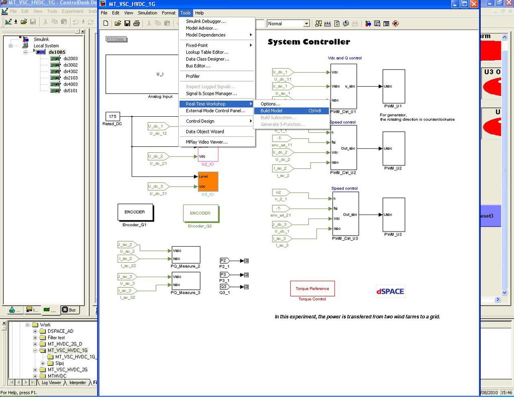

118 109

119 2.7 Find the interface of Instrumentation, chose Animation mode. It is for reading and writing the real-time data. 2.8 Check the variable transformer set to zero and the state of output breaker is off. 2.9 Turn on the wall switch of the relay. Push the green button of the relay. A crisp sound shows the relay is ready Turn on the output breaker of the variable transformer slowly. A deep sound shows the variable transformer is ready. Adjust the L-L voltage RMS value to 140 V. (the calibration equals to 38 approximately) 2.11 Back to the screen of the computer, and find the interface of switch-faults. Left click the on button for turning on the U1_main. 110
. After 10 seconds, click the green bottom Set Index to Zero (G1) in the mid of the screen.")
120 Two sounds can be heard for confirming Repeat the step 2.11 for U2_main and U3_main of the interface of switch-fault Find the interface of pwm_control. Tick the initial in the PWM_en_2 (the bottom orange one). After 10 seconds, click the green bottom Set Index to Zero (G1) in the mid of the screen. After 10 seconds, also click the purple button Set Index to Zero (G2) in the right of the screen. After that, un-tick the initial in the PWM_en_2 (the bottom orange one). 111
121 2.14 Turn on the main wall switch of driver cabinet. Turn on the switch in the door of the driver cabinet Find the interface of pwm_control. Set the DC voltage Vdc_ref/Value equals to 250 V and reactive power 0_ref/Value equals to 0. Set the frequency of PMSG 1 and PMSG 2 Freq/Value equal to 75 Hz. (In this particular case, 75 Hz means 1500 r/m for PMSG due to np=60f) 2.16 In the interface of pwm_control, tick the check of PWM_en_1 to enable the converter 1 for gird side. Then find the interface of switch_faults, check no error is shown on the screen. 112

122 2.17 Find the interface of the pwm_control. Tick the check of PWM_en_2 to enable the converter 2&3 for wind farms Find the interface of torque control. Set the Tm1 and Tm2 equal to small numbers (both are 2 in picture) for starting up the PMSGs. 113


123 2.19 Find interface of pwm_control. Tick the green and purple 1 bottoms of PI_En/Value to enable PI controllers Turn the model button on the door of driver cabinet from 0 to auto. 114
High Voltage DC Transmission 2
 High Voltage DC Transmission 2 1.0 Introduction Interconnecting HVDC within an AC system requires conversion from AC to DC and inversion from DC to AC. We refer to the circuits which provide conversion
Introduction to HVDC Transmission. High Voltage Direct Current (HVDC) Transmission
 Transmission") Lecture 29 Introduction to HVDC Transmission Series Compensation 1 Fall 2003 High Voltage Direct Current (HVDC) Transmission Update to Edison s Vision AC Power Generation at Relatively Lower Voltage» Step
Lecture 29 Introduction to HVDC Transmission Series Compensation 1 Fall 2003 High Voltage Direct Current (HVDC) Transmission Update to Edison s Vision AC Power Generation at Relatively Lower Voltage» Step
Design, Control and Application of Modular Multilevel Converters for HVDC Transmission Systems by Kamran Sharifabadi, Lennart Harnefors, Hans-Peter
 1 Design, Control and Application of Modular Multilevel Converters for HVDC Transmission Systems by Kamran Sharifabadi, Lennart Harnefors, Hans-Peter Nee, Staffan Norrga, Remus Teodorescu ISBN-10: 1118851560
HVDC Solutions for Integration of the Renewable Energy Resources
 HVDC Solutions for Integration of the Renewable Energy Resources Comparison of Technical Alternatives and System Configurations Marcus Haeusler Energy Management, Large Transmission Solutions Siemens AG
VSC Transmission. Presentation Overview. CIGRE B4 HVDC and Power Electronics HVDC Colloquium, Oslo, April LCC HVDC Transmission
 CIGRE B4 HVDC and Power Electronics HVDC Colloquium, Oslo, April 2006 VSC Transmission presented by Dr Bjarne R Andersen, Andersen Power Electronic Solutions Ltd Presentation Overview - Basic Characteristics
The University of Nottingham
 The University of Nottingham Power Electronic Converters for HVDC Applications Prof Pat Wheeler Power Electronics, Machines and Control (PEMC) Group UNIVERSITY OF NOTTINGHAM, UK Email pat.wheeler@nottingham.ac.uk
Aalborg Universitet. Design and Control of A DC Grid for Offshore Wind Farms Deng, Fujin. Publication date: 2012
 Aalborg Universitet Design and Control of A DC Grid for Offshore Wind Farms Deng, Fujin Publication date: 2012 Document Version Publisher's PDF, also known as Version of record Link to publication from
A cost effective hybrid HVDC transmission system with high performance in DC line fault handling
 2, rue d Artois, F-758 PARIS B4-7 CIGRE 28 http : //www.cigre.org A cost effective hybrid HVDC transmission system with high performance in DC line fault handling Mats Andersson, Xiaobo ang and ing-jiang
USE OF HVDC MULTI TERMINAL OPTIONS FOR FUTURE UPGRADE OF THE NATIONAL GRID
 USE OF HVDC MULTI TERMINAL OPTIONS FOR FUTURE UPGRADE OF THE NATIONAL GRID JOS ARRILLAGA Emeritus Professor, FIEE, FIEEE, MNZM 2/77 HINAU STREET, RICCARTON CHRISTCHURCH ARRILLJ@ELEC.CANTERBURY.AC.NZ TELEPHONE
Trans Bay Cable A Breakthrough of VSC Multilevel Converters in HVDC Transmission
 Trans Bay Cable A Breakthrough of VSC Multilevel Converters in HVDC Transmission Siemens AG Power Transmission Solutions J. Dorn, joerg.dorn@siemens.com CIGRE Colloquium on HVDC and Power Electronic Systems
Modelling of VSC-HVDC for Slow Dynamic Studies. Master s Thesis in Electric Power Engineering OSCAR LENNERHAG VIKTOR TRÄFF
 Modelling of VSC-HVDC for Slow Dynamic Studies Master s Thesis in Electric Power Engineering OSCAR LENNERHAG VIKTOR TRÄFF Department of Energy and Environment Division of Electric Power Engineering Chalmers
Session 7. Connecting offshore wind farms to the onshore grid
 Session 7 Connecting offshore wind farms to the onshore grid Dr Mike Barnes Present situation: Most windfarms onshore or AC connected Next generation of wind-farms will be far offshore (source TimesOnline)
Dynamic Stability Improvement of Power System with VSC-HVDC Transmission
 Dynamic Stability Improvement of Power System with VSC-HVDC Transmission A Thesis submitted in partial fulfilment of the Requirements for the Award of the degree of Master of Technology In Industrial Electronics
Introduction to HVDC in GB. Ian Cowan Simulation Engineer 12 March 2018
 Introduction to HVDC in GB Ian Cowan Simulation Engineer 12 March 2018 Contents 1) History of Electricity Networks 2) Overview of HVDC 3) Existing Schemes 4) Future Schemes 5) Regulation and Ownership
IMPORTANCE OF VSC IN HVDC
 IMPORTANCE OF VSC IN HVDC Snigdha Sharma (Electrical Department, SIT, Meerut) ABSTRACT The demand of electrical energy has been increasing day by day. To meet these high demands, reliable and stable transmission
Voltage Source Converter Modelling
 Voltage Source Converter Modelling Introduction The AC/DC converters in Ipsa represent either voltage source converters (VSC) or line commutated converters (LCC). A single converter component is used to
New Converter Topologies for High-Voltage Dc Converters. Prof. Ani Gole University of Manitoba, Canada
 New Converter Topologies for High-Voltage Dc Converters Prof. Ani Gole University of Manitoba, Canada IEEE Southern Alberta Section, Sept. 12, 2011 Outline Brief History of HVDC Transmission Conventional
Highgate Converter Overview. Prepared by Joshua Burroughs & Jeff Carrara IEEE PES
 Highgate Converter Overview Prepared by Joshua Burroughs & Jeff Carrara IEEE PES Highgate Converter Abstract Introduction to HVDC Background on Highgate Operation and Control schemes of Highgate 22 Why
29 Level H- Bridge VSC for HVDC Application
 29 Level H- Bridge VSC for HVDC Application Syamdev.C.S 1, Asha Anu Kurian 2 PG Scholar, SAINTGITS College of Engineering, Kottayam, Kerala, India 1 Assistant Professor, SAINTGITS College of Engineering,
Design, Control and Application of Modular Multilevel Converters for HVDC Transmission Systems by Kamran Sharifabadi, Lennart Harnefors, Hans-Peter
 1 Design, Control and Application of Modular Multilevel Converters for HVDC Transmission Systems by Kamran Sharifabadi, Lennart Harnefors, Hans-Peter Nee, Staffan Norrga, Remus Teodorescu ISBN-10: 1118851560
Zambezi (previously Caprivi) Link HVDC Interconnector: Review of Operational Performance in the First Five Years
 Link HVDC Interconnector: Review of Operational Performance in the First Five Years") 21, rue d Artois, F-758 PARIS B4-18 CIGRE 216 http : //www.cigre.org Zambezi (previously Caprivi) Link HVDC Interconnector: Review of Operational Performance in the First Five Years T G MAGG, Power System
21, rue d Artois, F-758 PARIS B4-18 CIGRE 216 http : //www.cigre.org Zambezi (previously Caprivi) Link HVDC Interconnector: Review of Operational Performance in the First Five Years T G MAGG, Power System
The rapid evolution of voltage Source Converters as applied to High Voltage DC power transmission Carl Barker
 The rapid evolution of voltage Source Converters as applied to High Voltage DC power transmission Carl Barker Chief Engineer HVDC Applications Tuesday 30 June 2015 HVDC Today Finding an increasing market
Chapter -3 ANALYSIS OF HVDC SYSTEM MODEL. Basically the HVDC transmission consists in the basic case of two
 Chapter -3 ANALYSIS OF HVDC SYSTEM MODEL Basically the HVDC transmission consists in the basic case of two convertor stations which are connected to each other by a transmission link consisting of an overhead
Joe Warner, Electric Power Industry Conference (EPIC), November 15, 2016 Advances in Grid Equipment Transmission Shunt Compensation
, November 15, 2016 Advances in Grid Equipment Transmission Shunt Compensation") Joe Warner, Electric Power Industry Conference (EPIC), November 15, 2016 Advances in Grid Equipment Transmission Shunt Compensation Slide 1 Excerpt from the BoA BoA: Book of Acronyms MSC/MSR: Mechanically
Joe Warner, Electric Power Industry Conference (EPIC), November 15, 2016 Advances in Grid Equipment Transmission Shunt Compensation Slide 1 Excerpt from the BoA BoA: Book of Acronyms MSC/MSR: Mechanically
Overview of Actuation Thrust
 Overview of Actuation Thrust Fred Wang Thrust Leader, UTK Professor ECE 620 CURENT Course September 13, 2017 Actuation in CURENT Wide Area Control of Power Power Grid Grid Measurement &Monitoring HVDC
2-Dimensional Control of VSC-HVDC
 2-Dimensional Control of VSC-HVDC Master Thesis Magnus Svean, Astrid Thoen Aalborg University Department of Energy Technology Copyright Aalborg University 2018 Title: 2-Dimensional Control of HVDC Semester:
Partial Power Operation of Multi-level Modular Converters under Subsystem Faults
 Partial Power Operation of Multi-level Modular Converters under Subsystem Faults Philip Clemow Email: philipclemow@imperialacuk Timothy C Green Email: tgreen@imperialacuk Michael M C Merlin Email: michaelmerlin7@imperialacuk
Multilink DC Transmission for Offshore Wind Power Integration
 Department of Energy Technology - Pontoppidanstræde Aalborg University, Denmark Multilink DC Transmission for Offshore Wind Power Integration Master thesis - th Semester, 2- Title: Multilink DC Transmission
International Journal of Engineering Research and General Science Volume 5, Issue 2, March-April, 2017 ISSN
 Analysis of H Link in Large Scale Offshore farm, Study and Comparison of LCC and SC Based H Links and Interconnection of Asynchronous Power Systems Utilizing SC-Based H Converter *Usman Raees Baig, **Mokhi
MMC Design Aspects and Applications. John Strauss Siemens AG.
 MMC Design Aspects and Applications John Strauss Siemens AG. John.Strauss@Siemens.com 1 VSC-HVDC with MMC Basic Scheme Reference HVDC PLUS Converter Arm Converter Module Power Module Electronics (PME)
Development of an Experimental Rig for Doubly-Fed Induction Generator based Wind Turbine
 Development of an Experimental Rig for Doubly-Fed Induction Generator based Wind Turbine T. Neumann, C. Feltes, I. Erlich University Duisburg-Essen Institute of Electrical Power Systems Bismarckstr. 81,
HVDC High Voltage Direct Current
 HVDC High Voltage Direct Current Typical HVDC Station BACK TO BACK CONVERTER STATION MONO POLAR WITH GROUND RETURN PA Back to Back Converters indicates that the Rectifiers & Inverters are located in the
Fundamental Concepts of Dynamic Reactive Compensation. Outline
 1 Fundamental Concepts of Dynamic Reactive Compensation and HVDC Transmission Brian K. Johnson University of Idaho b.k.johnson@ieee.org 2 Outline Objectives for this panel session Introduce Basic Concepts
U I. HVDC Control. LCC Reactive power characteristics
 Lecture 29 HVDC Control Series Compensation 1 Fall 2017 LCC Reactive power characteristics LCC HVDC Reactive compensation by switched filters and shunt capacitor banks Operates at lagging power factor
Grid integration of offshore wind farms using HVDC links: HVDC-VSC technology overview
 Grid integration of offshore wind farms using HVDC links: HVDC-VSC technology overview ICREPQ 2013, Basque Country, 22 nd March 2013 Salvador Ceballos Salvador.ceballos@tecnalia.com Introduction OWPP layouts
Reactive Power and AC Voltage Control of LCC HVDC System with Digitally Tunable Controllable Capacitors
 International Journal for Modern Trends in Science and Technology Volume: 03, Issue No: 06, June 2017 ISSN: 2455-3778 http://www.ijmtst.com Reactive Power and AC Voltage Control of LCC HVDC System with
Operation of a Three-Phase PWM Rectifier/Inverter
 Exercise 1 Operation of a Three-Phase PWM Rectifier/Inverter EXERCISE OBJECTIVE When you have completed this exercise, you will be familiar with the block diagram of the three-phase PWM rectifier/inverter.
VOLTAGE SOURCE CONVERTER BASED HVDC TRANSMISSION SYSTEM
 VOLTAGE SOURCE CONVERTER BASED HVDC TRANSMISSION SYSTEM Harish A. Patil 1, Ashwini K. Khairnar 2, Bhushan H. Patil 3 1 PGScholar, ElectricalEngineering Department, KCE COEIT Jalgaon, MS, (India) 2 PG Scholar,
Power Quality enhancement of a distribution line with DSTATCOM
 ower Quality enhancement of a distribution line with DSTATCOM Divya arashar 1 Department of Electrical Engineering BSACET Mathura INDIA Aseem Chandel 2 SMIEEE,Deepak arashar 3 Department of Electrical
DOWNLOAD PDF POWER ELECTRONICS DEVICES DRIVERS AND APPLICATIONS
 Chapter 1 : Power Electronics Devices, Drivers, Applications, and Passive theinnatdunvilla.com - Google D Download Power Electronics: Devices, Drivers and Applications By B.W. Williams - Provides a wide
Improvement of Rotor Angle Stability and Dynamic Performance of AC/DC Interconnected Transmission System
 Improvement of Rotor Angle Stability and Dynamic Performance of AC/DC Interconnected Transmission System 1 Ramesh Gantha 1, Rasool Ahemmed 2 1 eee Kl University, India 2 AsstProfessor, EEE KL University,
INSTANTANEOUS POWER CONTROL OF D-STATCOM FOR ENHANCEMENT OF THE STEADY-STATE PERFORMANCE
 INSTANTANEOUS POWER CONTROL OF D-STATCOM FOR ENHANCEMENT OF THE STEADY-STATE PERFORMANCE Ms. K. Kamaladevi 1, N. Mohan Murali Krishna 2 1 Asst. Professor, Department of EEE, 2 PG Scholar, Department of
IJEETC. InternationalJournalof. ElectricalandElectronicEngineering& Telecommunications.
 IJEETC www.ijeetc.com InternationalJournalof ElectricalandElectronicEngineering& Telecommunications editorijeetc@gmail.com oreditor@ijeetc.com Int. J. Elec&Electr.Eng&Telecoms. 2015 Anoop Dhayani A P et
HVDC Transmission and AC hubs for Offshore Wind Generation
 HVDC Transmission and AC hubs for Offshore Wind Generation Jonathan Mark Stevens School of Engineering Cardiff University A thesis submitted for the degree of Doctor of Philosophy September, 2015 To my
Experience with Connecting Offshore Wind Farms to the Grid
 Oct.26-28, 2011, Thailand PL-22 CIGRE-AORC 2011 www.cigre-aorc.com Experience with Connecting Offshore Wind Farms to the Grid J. FINN 1, A. SHAFIU 1,P. GLAUBITZ 2, J. LOTTES 2, P. RUDENKO 2, M: STEGER
Open Access Simulation Toolbox for Wind Power Transmission using High Voltage Direct Current Technology
 Open Access Simulation Toolbox for Wind Power Transmission using High Voltage Direct Current Technology Daniel Adeuyi (Cardiff University, Wales) Sheng WANG, Carlos UGALDE-LOO (Cardiff University, Wales);
1400 MW New Zealand HVDC Upgrade: Introducing Power Modulation Controls and Round Power Mode
 1400 MW New Zealand HVDC Upgrade: Introducing Power Modulation Controls and Mode Simon P. Teeuwsen Network Consulting Siemens AG Erlangen, Germany simonp.teeuwsen@siemens.com Abstract The existing HVDC
It s time to connect with offshore wind supplement
 It s time to connect with offshore wind supplement 2 ABB Table of Contents 1. Introduction 2. Applications 3. Features 4. Products 5. Descriptions 6. System engineering 7. References 8. Index After the
Recent trends in High Voltage Direct Current (HVDC)Transmission Systems Abstract
Transmission Systems Abstract") Recent trends in High Voltage Direct Current (HVDC)Transmission Systems Abstract During the latest 20 years, HVDC has become the dominating technology for long distance transmission of bulk power. The
Recent trends in High Voltage Direct Current (HVDC)Transmission Systems Abstract During the latest 20 years, HVDC has become the dominating technology for long distance transmission of bulk power. The
Integration of Offshore Wind Farms Through High Voltage Direct Current Networks. Luke Livermore School of Engineering Cardiff University
 Integration of Offshore Wind Farms Through High Voltage Direct Current Networks Luke Livermore School of Engineering Cardiff University A thesis submitted for the degree of Doctor of Philosophy January
A New Network Proposal for Fault-Tolerant HVDC Transmission Systems
 A New Network Proposal for Fault-Tolerant HVDC Transmission Systems Malothu Malliswari 1, M. Srinu 2 1 PG Scholar, Anurag Engineering College 2 Assistant Professor, Anurag Engineering College Abstract:
Bipole III Transmission Project
 Bipole III Transmission Project Clean Environment Commission Public Hearings Fall 2012 System Planning Ronald Mazur BP III Keewantinoow Limestone Kettle Kelsey Jenpeg Grand Rapids OVERVIEW Transmission
MODELLING AND CONTROL OF HYBRID
 MODELLING AND CONTROL OF HYBRID LCC HVDC SYSTEM by YING XUE A thesis submitted to The University of Birmingham for the degree of DOCTOR OF PHILOSOPHY School of Electronic, Electrical and Systems Engineering
AORC Technical meeting 2014
 http : //www.cigre.org B4-112 AORC Technical meeting 214 HVDC Circuit Breakers for HVDC Grid Applications K. Tahata, S. Ka, S. Tokoyoda, K. Kamei, K. Kikuchi, D. Yoshida, Y. Kono, R. Yamamoto, H. Ito Mitsubishi
Overview of Actuation Thrust
 Overview of Actuation Thrust Fred Wang Thrust Leader, UTK Professor Prepared for CURENT Course September 4, 2013 Actuation in CURENT Wide Area Control of Power Power Grid Grid Measurement &Monitoring HVDC
Sensitivity Analysis of MTDC Control System
 Aalborg University Energy Department Sensitivity Analysis of MTDC Control System Long Master Thesis Aalborg 2016 Przemyslaw Drozd Title: Sensitivity Analysis of MTDC Control System Semester: 4 th M.SC
Compensation of Distribution Feeder Loading With Power Factor Correction by Using D-STATCOM
 Compensation of Distribution Feeder Loading With Power Factor Correction by Using D-STATCOM N.Shakeela Begum M.Tech Student P.V.K.K Institute of Technology. Abstract This paper presents a modified instantaneous
THE first use of direct current for electrical power transmission
 18 IEEE TRANSACTIONS ON POWER ELECTRONICS, VOL. 30, NO. 1, JANUARY 2015 Modular Multilevel Converters for HVDC Applications: Review on Converter Cells and Functionalities Alireza Nami, Member, IEEE, Jiaqi
MODELING AND ANALYSIS OF IMPEDANCE NETWORK VOLTAGE SOURCE CONVERTER FED TO INDUSTRIAL DRIVES
 Int. J. Engg. Res. & Sci. & Tech. 2015 xxxxxxxxxxxxxxxxxxxxxxxx, 2015 Research Paper MODELING AND ANALYSIS OF IMPEDANCE NETWORK VOLTAGE SOURCE CONVERTER FED TO INDUSTRIAL DRIVES N Lakshmipriya 1* and L
Introduction to HVDC VSC HVDC
 Introduction to HVDC VSC HVDC Dr Radnya A Mukhedkar Group Leader, Senior Principal Engineer System Design GRID August 2010 The Voltage Sourced Converter Single Phase Alternating Voltage Output Steady DC
TSFS11 HVDC. Lecture 13 Tomas Jonsson ISY/EKS
 TSFS11 HVDC Lecture 13 Tomas Jonsson ISY/EKS Outline HVDC Introduction Classic HVDC Basic principles VSC HVDC Basic principles VSC in the power grid - Wind applications HVDC Introduction High Voltage Direct
Analysis of the Effectiveness of Grid Codes for Offshore Wind Farms Connected to Onshore Grid via VSC-Based HVDC
 Conference of the Wind Power Engineering Community Analysis of the Effectiveness of Grid Codes for Offshore Wind Farms Connected to Onshore Grid via VSC-Based HVDC Moritz Mittelstaedt, Andreas Roehder,.Hendrik
IJSRD - International Journal for Scientific Research & Development Vol. 2, Issue 07, 2014 ISSN (online):
:") IJSRD - International Journal for Scientific Research & Development Vol. 2, Issue 07, 2014 ISSN (online): 2321-0613 Control and Analysis of VSC based High Voltage DC Transmission Tripti Shahi 1 K.P.Singh
IJSRD - International Journal for Scientific Research & Development Vol. 2, Issue 07, 2014 ISSN (online): 2321-0613 Control and Analysis of VSC based High Voltage DC Transmission Tripti Shahi 1 K.P.Singh
Stability Enhancement for Transmission Lines using Static Synchronous Series Compensator
 Stability Enhancement for Transmission Lines using Static Synchronous Series Compensator Ishwar Lal Yadav Department of Electrical Engineering Rungta College of Engineering and Technology Bhilai, India
The Effect of an Embedded VSC-HVDC link on the Transient stability of the Dutch and German Transmission Systems
 The Effect of an Embedded VSC-HVDC link on the Transient stability of the Dutch and German Transmission Systems Polykarpos-Antre Christoforidis Master of Science Thesis Faculty of Electrical Engineering,
East-South HVDC Interconnector II, India : in commercial operation since 2003
 8006/0 5 HVDC / FACTS Highlights http://www.siemens.com/facts http://www.siemens.com/hvdc NEW! >>> Welcome to Siemens Highlights & Innovations in Transmission and Distribution East-South HVDC Interconnector
Dynamic Series Compensation for the Reinforcement of Network Connections with High Wind Penetration
 Dynamic Series Compensation for the Reinforcement of Network Connections with High Wind Penetration Juan Carlos Nambo-Martinez Kamila Nieradzinska Olimpo Anaya-Lara EERA Deepwind 2014 23 January 2014,
PUBLICATIONS OF PROBLEMS & APPLICATION IN ENGINEERING RESEARCH - PAPER CSEA2012 ISSN: ; e-issn:
 POWER FLOW CONTROL BY USING OPTIMAL LOCATION OF STATCOM S.B. ARUNA Assistant Professor, Dept. of EEE, Sree Vidyanikethan Engineering College, Tirupati aruna_ee@hotmail.com 305 ABSTRACT In present scenario,
Intelligence Controller for STATCOM Using Cascaded Multilevel Inverter
 Journal of Engineering Science and Technology Review 3 (1) (2010) 65-69 Research Article JOURNAL OF Engineering Science and Technology Review www.jestr.org Intelligence Controller for STATCOM Using Cascaded
Copyright 2012 IEEE. Paper presented at 2012 IEEE Workshop on Complexity in Engineering 11 June, Aachen,
 Copyright 22 IEEE Paper presented at 22 IEEE Workshop on Complexity in Engineering June, Aachen, Germany 22 This material is posted here with the permission of the IEEE. Such permission of the IEEE does
Facilitating Bulk Wind Power Integration Using LCC HVDC
 21, rue d Artois, F-758 PARIS CIGRE US National Committee http : //www.cigre.org 213 Grid of the Future Symposium Facilitating Bulk Wind Power Integration Using LCC HVDC A. HERNANDEZ * R.MAJUMDER W. GALLI
Investigation of D-Statcom Operation in Electric Distribution System
 J. Basic. Appl. Sci. Res., (2)29-297, 2 2, TextRoad Publication ISSN 29-434 Journal of Basic and Applied Scientific Research www.textroad.com Investigation of D-Statcom Operation in Electric Distribution
ATC s Mackinac Back to Back. Summary
 ATC s Mackinac Back to Back HVDC Project Update Michael B. Marz American Transmission Company Summary The Need For Flow Control at Mackinac Mackinac Flow Control Requirements Available Flow Control Technologies
ZERO PHASE SEQUENCE VOLTAGE INJECTION FOR THE ALTERNATE ARM CONVERTER
 ZERO PHASE SEQUENCE VOLTAGE INJECTION FOR THE ALTERNATE ARM CONVERTER F J Moreno*, M M C Merlin, D R Trainer*, T C Green, K J Dyke* *Alstom Grid, St Leonards Ave, Stafford, ST17 4LX Imperial College, South
A new control scheme for an HVDC transmission link with capacitorcommutated converters having the inverter operating with constant alternating voltage
 21, rue d Artois, F-758 PARIS B4_16_212 CIGRE 212 http : //www.cigre.org A new control scheme for an HVDC transmission link with capacitorcommutated converters having the inverter operating with constant
Grid West Project HVDC Technology Review
 Prepared by For Reference Les Brand / Ranil de Silva / Errol Bebbington / Kalyan Chilukuri EirGrid JA4846 Date 17 th December 2014 Revision Table Revision Issue Date Description 0 12/12/2014 Final for
CHAPTER 4 MULTI-LEVEL INVERTER BASED DVR SYSTEM
 64 CHAPTER 4 MULTI-LEVEL INVERTER BASED DVR SYSTEM 4.1 INTRODUCTION Power electronic devices contribute an important part of harmonics in all kind of applications, such as power rectifiers, thyristor converters
High Voltage DC Transmission Prof. Dr. S. N. Singh Department of Electrical Engineering Indian Institute of Technology Kanpur
 High Voltage DC Transmission Prof. Dr. S. N. Singh Department of Electrical Engineering Indian Institute of Technology Kanpur Module No. # 01 Lecture No. # 03 So, in last two lectures, we saw the advantage
Improved Transient Compensation Using PI-SRF Control Scheme Based UHVDC For Offshore Wind Power Plant
 Improved Transient Compensation Using PI-SRF Control Scheme Based UHVDC For Offshore Wind Power Plant Sangeetha M 1, Arivoli R 2, Karthikeyan B 3 1 Assistant Professor, Department of EEE, Imayam College
ECE 422/522 Power System Operations & Planning/Power Systems Analysis II 5 - Reactive Power and Voltage Control
 ECE 422/522 Power System Operations & Planning/Power Systems Analysis II 5 - Reactive Power and Voltage Control Spring 2014 Instructor: Kai Sun 1 References Saadat s Chapters 12.6 ~12.7 Kundur s Sections
Design, Control and Application of Modular Multilevel Converters for HVDC Transmission Systems by Kamran Sharifabadi, Lennart Harnefors, Hans-Peter
 1 Design, Control and Application of Modular Multilevel Converters for HVDC Transmission Systems by Kamran Sharifabadi, Lennart Harnefors, Hans-Peter Nee, Staffan Norrga, Remus Teodorescu ISBN-10: 1118851560
International Journal of Emerging Technology in Computer Science & Electronics (IJETCSE) ISSN: Volume 8 Issue 1 APRIL 2014.
 ISSN: Volume 8 Issue 1 APRIL 2014.") WIND TURBINE VOLTAGE STABILITY USING FACTS DEVICE PRAVEEN KUMAR.R# and C.VENKATESH KUMAR* #M.E.POWER SYSTEMS ENGINEERING, EEE, St. Joseph s college of engineering, Chennai, India. *Asst.Professor, Department
WIND TURBINE VOLTAGE STABILITY USING FACTS DEVICE PRAVEEN KUMAR.R# and C.VENKATESH KUMAR* #M.E.POWER SYSTEMS ENGINEERING, EEE, St. Joseph s college of engineering, Chennai, India. *Asst.Professor, Department
Effects and Mitigation of Post-Fault Commutation Failures in Line-Commutated HVDC Transmission System
 IEEE International Symposium on Industrial Electronics (ISIE 9) Seoul Olympic Parktel, Seoul, Korea July 5-8, 9 Effects and Mitigation of Post-Fault Commutation Failures in Line-Commutated HVDC Transmission
CHAPTER 4 MODIFIED H- BRIDGE MULTILEVEL INVERTER USING MPD-SPWM TECHNIQUE
 58 CHAPTER 4 MODIFIED H- BRIDGE MULTILEVEL INVERTER USING MPD-SPWM TECHNIQUE 4.1 INTRODUCTION Conventional voltage source inverter requires high switching frequency PWM technique to obtain a quality output
This document is a preview generated by EVS
 TECHNICAL REPORT CLC/TR 50609 RAPPORT TECHNIQUE TECHNISCHER BERICHT February 2014 ICS 29.240.01 English version Technical Guidelines for Radial HVDC Networks Directives techniques pour les réseaux HVDC
HVDC Transmission. Michael Muhr. Institute of High Voltage Engineering and System Performance Graz University of Technology Austria P A S S I O N
 S C I E N C E P A S S I O N T E C H N O L O G Y HVDC Transmission Michael Muhr Graz University of Technology Austria www.tugraz.at 1 Definition HV High Voltage AC Voltage > 60kV 220kV DC Voltage > 60kV
ATC s Mackinac Back-to-Back HVDC Project: Planning and Operation Considerations for Michigan s Eastern Upper and Northern Lower Peninsulas
 21, rue d Artois, F-75008 PARIS CIGRE US National Committee http : //www.cigre.org 2013 Grid of the Future Symposium ATC s Mackinac Back-to-Back HVDC Project: Planning and Operation Considerations for
COPYRIGHTED MATERIAL. Introduction. 1.1 Early developments
 1 Introduction 1.1 Early developments A variety of electronic valves was tried in the first part of the twentieth century for the conversion of power from AC to DC and vice versa. The mercury-arc valve
Design and Simulation of Passive Filter
 Chapter 3 Design and Simulation of Passive Filter 3.1 Introduction Passive LC filters are conventionally used to suppress the harmonic distortion in power system. In general they consist of various shunt
Control of MMC in HVDC Applications
 Department of Energy Technology Aalborg University, Denmark Control of MMC in HVDC Applications Master Thesis 30/05/2013 Artjoms Timofejevs Daniel Gamboa Title: Semester: Control of MMC in HVDC applications
To Study The MATLAB Simulation Of A Single Phase STATCOM And Transmission Line
 To Study The MATLAB Simulation Of A Single Phase And Transmission Line Mr. Nileshkumar J. Kumbhar Abstract-As an important member of FACTS family, (Static Synchronous Compensator) has got more and more
OVERVIEW OF SVC AND STATCOM FOR INSTANTANEOUS POWER CONTROL AND POWER FACTOR IMPROVEMENT
 OVERVIEW OF SVC AND STATCOM FOR INSTANTANEOUS POWER CONTROL AND POWER FACTOR IMPROVEMENT Harshkumar Sharma 1, Gajendra Patel 2 1 PG Scholar, Electrical Department, SPCE, Visnagar, Gujarat, India 2 Assistant
VSC Based HVDC Active Power Controller to Damp out Resonance Oscillation in Turbine Generator System
 VSC Based HVDC Active Power Controller to Damp out Resonance Oscillation in Turbine Generator System Rajkumar Pal 1, Rajesh Kumar 2, Abhay Katyayan 3 1, 2, 3 Assistant Professor, Department of Electrical
OPTIMIZATION OF MULTILINK DC TRANSMISSION FOR SUPERGRID FUTURE CONCEPTS
 DEPARTAMENT OF ENERGY TECHNOLOGY PONTOPPIDANSTRᴁDE 101 OPTIMIZATION OF MULTILINK DC TRANSMISSION FOR SUPERGRID FUTURE CONCEPTS MASTER THESIS Title: Semester: Semester theme: Optimization of Multilink DC
Impacts of DC Circuit Breakers on AC/DC System Stability Subject to DC Faults
 216 International High Voltage Direct Current Conference (HVDC 216) Impacts of DC Circuit Breakers on AC/DC System Stability Subject to DC Faults Gen Li 1, Jun Liang 1, Carlos E Ugalde-Loo 1, Paul Coventry
Comparison of Hybrid Asymmetric and Conventional Multilevel Inverters for Medium Voltage Drive Applications
 Comparison of Hybrid Asymmetric and Conventional Multilevel Inverters for Medium Voltage Drive Applications Master of Science Thesis in the Master s programme Electric Power Engineering AMIR SAJJAD BAHMAN
Technical and Economic Analysis of Connecting Nuclear Generation to the National Electricity Transmission System via HVDC Technology.
 Technical and Economic Analysis of Connecting Nuclear Generation to the National Electricity Transmission System via HVDC Technology Richard Poole School of Engineering and Technology This thesis is submitted
Modeling and Simulation of STATCOM
 Modeling and Simulation of STATCOM Parimal Borse, India Dr. A. G. Thosar Associate Professor, India Samruddhi Shaha, India Abstract:- This paper attempts to model and simulate Flexible Alternating Current
OPERATION AND CONTROL OF MULTI-TERMINAL DC (MTDC) GRIDS
 GRIDS") OPERATION AND CONTROL OF MULTI-TERMINAL DC (MTDC) GRIDS June 2013 Master Thesis Marta Bobis Uría Title: Operation and Control of Multi-Terminal DC (MTDC) Grids Semester: 10th Semester Semester theme: Master
OPERATION AND CONTROL OF MULTI-TERMINAL DC (MTDC) GRIDS June 2013 Master Thesis Marta Bobis Uría Title: Operation and Control of Multi-Terminal DC (MTDC) Grids Semester: 10th Semester Semester theme: Master
Power System Reliability and Transfer Capability Improvement by VSC- HVDC (HVDC Light )
") 21, rue d Artois, F-75008 PARIS SECURITY AND RELIABILITY OF ELECTRIC POWER SYSTEMS http : //www.cigre.org CIGRÉ Regional Meeting June 18-20, 2007, Tallinn, Estonia Power System Reliability and Transfer
21, rue d Artois, F-75008 PARIS SECURITY AND RELIABILITY OF ELECTRIC POWER SYSTEMS http : //www.cigre.org CIGRÉ Regional Meeting June 18-20, 2007, Tallinn, Estonia Power System Reliability and Transfer