ple mateur Band Aerials E. M. NOLL
|
|
|
- Sarah Laurel Haynes
- 5 years ago
- Views:
Transcription


1 ple mateur Band Aerials E. M. NOLL


2 0)ew* olei 01 oir'w1 Essex County Council You can ask us to obtain books, videos, C.D.s and cassettes which are not in our stock - enquire at your local library for details
3 25 SIMPLE AMATEUR BAND AERIALS 1,30001,1


4 saw OTHER TITLES IN PREPARATION 25 Simple Broadcast Band Aerials 25 Simple Indoor and Window Aerials 25 Simple MW and LW Aerials
5 25 SIMPLE AMATEUR BAND AERIALS by E. M. NOLL BERNARD BABANI (publishing) LTD THE GRAMPIANS SHEPHERDS BUSH ROAD LONDON W6 7NF ENGLAND
6 PLEASE NOTE Although every care has been taken with the production of this book to ensure that any projects, designs, modifications and/or programs etc. contained herein, operate in a correct and safe manner and also that any components specified are normally available in Great Britain, the Publishers do not accept responsibility in any way for the failure, including fault in design, of any project, design, modification or program to work correctly or to cause damage to any other equipment that it may be connected to or used in conjunction with, or in respect of any other damage or injury that may be so caused, nor do the Publishers accept responsibility in any way for the failure to obtain specified components. Notice is also given that if equipment that is still under warranty is modified in any way or used or connected with home -built equipment then that warranty may be void BERNARD BABANI (publishing) LTD First Published - August 1983 Reprinted - November 1993 British Library Cataloguing in Publication Data Noll, Edward M. 25 simple amateur band aerials. - (BP125) 1 Antennas (Electronics) - Amateurs' manuals I. Title '028'3 TK9956 ISBN Printed and bound in Great Britain by Cox & Wyman Ltd, Reading o 4
7 ABOUT THE AUTHOR Ed Noll is an established American technical author who has written many books, articles and instruction manuals as well as having lectured and taught radio communications at various universities in the U.S.A. He has worked on the staff of a number of broadcasting stations and as a consulting engineer.
8 CONTENTS Page INTRODUCTION 1 1. DIPOLE 3 2. HALF -WAVELENGTH SLOPER 5 3. INVERTED DIPOLE 5 4. TWO -MAST INVERTED DIPOLE 8 5. TWO- AND THREE -BAND INVERTED DIPOLES /2 WAVELENGTH AERIAL INVERTED 3/4 WAVELENGTH AERIAL RANDOM WIRE DIPOLE -REFLECTOR DIPOLE -DIRECTOR THREE -ELEMENT BEAM PHASED ARRAY TWO -ELEMENT BROADSIDE COLLINEAR TRIANGLE HIGH -FREQUENCY TRIANGLE TWO -ELEMENT TRIANGLE LITTLE VEE-BEAM LITTLE RHOMBIC SQUARED QUARTER -WAVE VERTICALS TELESCOPING VERTICALS UMBRELLA VERTICALS PHASED VERTICALS TWO -ELEMENT BROADSIDE END -FIRE BROADSIDE COMBINE 50
9 Page DIMENSION TABLES 53 LENGTH CONVERSION TABLE 62 EQUATIONS 63 TYPES OF CABLES 63
10 INTRODUCTION Many cheap and simple aerials perform very well. Don't let the "keep up with the Jones's aerial -farm phobia" spoil your ham radio enjoyment. You don't need the highest aerials and maximum -gain types to have fun and relaxation. Plan, gather components and erect your own. Be amazed at the fine results you can obtain spending limited funds. The twenty-five aerials, low cost and sure performers, start with the simple dipole and proceed to beam, triangle and even a mini -rhombic made from four TV masts and about 400 feet of surplus wire. Economy components were used in constructing all of these aerials over a period of many years. Aerial wire was most often vinyl -covered 16 SWG (14 AWG) or 18 SWG (16 AWG) solid wire that can be found in surplus outlets. Bare stranded 16 SWG or 18 SWG wire was also used. A 20 -meter three - element wire beam no more than 16 feet above ground sent out a fine QRP signal across the country. Masts were largely the TV variety or wooden poles. Popular was the three -section telescoping type, using the bottom two sections without guying for low aerials and one set of nylon guys when stretching up to three section heights. Bases were set down in rocks and sand for a temporary mount, in cement, for more permanent installation. A four -section mast was used for some aerials, but none of the twenty-five aerials were higher than 35 feet (WAC and DXCC were attained with under 200W PEP). Shop for masts at ham and component shops or surplus stores. The various cables used were RG59U-58U coaxials, ohm open wire, and good quality 300 -ohm twin lead. Coaxial line was used for the short aerials; parallel lines for the vee's and rhombics. A tuner is an excellent investment for the aerial experimenter and multiband operator. Often a limited aerial -point mismatch is not a serious loss problem. The real culprit that such an aerial mismatch causes is the resultant mismatch between line and transmitter that can occur. Modern solidstate transmitter output drops alarmingly with mismatch. A 1
11 tuner avoids this difficulty. A tuner is essential when using parallel lines. Additional benefits are the reduction in harmonic radiation and, on receive, noise level reduction and less off -channel interference. A big help is an old vacuum -valve design CW transmitter that can be used in tuning aerials and adjusting tuners to near final settings before connection is made to your main transmitter. After the aerial discussion you will find a complete set of dimension tables that will help you to spot an aerial on a particular frequency. Dimensions are given for various style aerials and other data needed for spacing and cutting phasing lengths. Dimensions for the new WARC bands are also given. Now go on and enjoy yourself! Be certain to read 1 through 7 before skipping back to other aerial types because many of the ideas introduced can be used in planning and constructing the aerial types that follow. Ed Noll 2
12 1. DIPOLE The dipole is a half wavelength aerial and is often considered the basic type and a reference aerial when making comparisons with other types. It is usually centre -fed which divides it into two quarter -wavelength segments. End -effect makes the resonant length of a dipole physically shorter than the calculated half -wavelength of free space. In the dimension chart you will notice that free space half -wavelength dimensions are given as well as the required dipole length to obtain resonance at a given frequency. This dimension in the chart considers end -effect. The dipole aerial has a figure -eight radiation pattern with maximum direction broadside to the wire direction. The lower the aerial is mounted, the less directive and sharp the aerial pattern becomes. In constructing the aerial it is advantageous to use a dipole - to -coax connector, Fig. 1. The two free ends of the dipole are connected to end insulators. The other end of each insulator is connect to the wire or nylon rope section that attaches to the mast or other support. An attractive alternative is to use nylon rope, running it through a support ring and on down to ground level. Such a halyard provides a convenient means for hoisting or lowering the aerial for making changes or trim -tuning. Theoretically the dipole should be mounted high and clear and run in a straight true line. Don't you believe it! You can have fun and good results if it is lower, near obstacles, and is even 30 degrees or more departed from a straight-line direction. The ultimate is great! However, sometimes you must think, "Do I need the ultimate to enjoy ham radio?" More often than not, especially when cutting higher frequency aerials, the aerial is not resonated at the exact frequency you desire. Sometimes the difference is unimportant. However, the influence of aerial's height and nearby obstacles may require additional trimming. An SWR meter is helpful in making such adjustments because the resonant frequency of the aerial system is indicated approximately by the frequency at which there is minimum SWR reading. 3


13 Hi ---1 /4 X --0. Insulator Fig. 1. Dipole H1/4A--7.I Dipole to coax connector Max. Directivity Min. -41E-110,
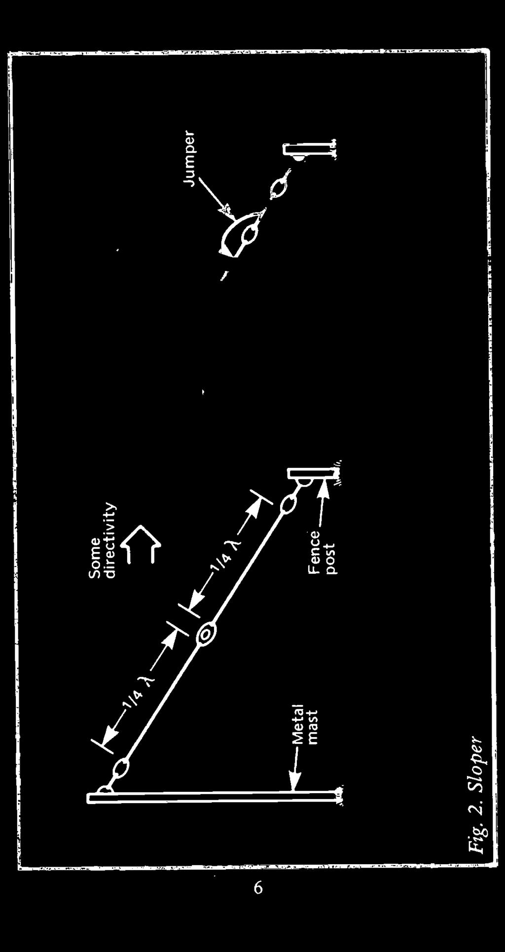
14 2. HALF -WAVELENGTH SLOPER The sloper is an economical dipole arrangement that saves ground area and requires but a single high -support structure. The lower support can be a metal or wooden fence post. If the high support is a metal mast, the sloper will have some directivity in the direction of the tilt as shown in Fig.2. Another advantage is that the aerial can be tuned to a degree at the accessible low end as shown. Sections of wire can be hung on the aerial or a jumper can be used to add a section of line to the aerial length when required. Thus the aerial can be tuned for a minimum SWR at chosen segments of the frequency band. In a typical installation, the top segment of the dipole can be cut to the centre frequency of a given band while the lower segment is cut to a higher frequency. Sections of line can then be jumped or added to this lower segment to move the net resonant frequency about the band for lower SWR when changing operation, for example, between the CW and phone sections of a band. 3. INVERTED DIPOLE The popular inverted dipole or inverted -V is shown in Fig.3. This is a fine performing aerial and also requires but a single high -support structure. Popular opinion states that it is more omnidirectional than the straight horizontal dipole. Also there seems to be substantial low angle vertical radiation off the aerial ends, which favors DX operations off the two ends. Often the ends must be shortened to attain resonance on a given frequency because of the influences of ground and apex angle. An advantage of the inverted dipole that should not be ignored is the ability to tune the aerial at the two accessible ends using hang -on sections of aerial or additional insulators and jumper arrangement as shown previously for the sloper in Fig.2. For example, the quarter -wave segments can be cut at the high -frequency end, say 3.8 MHz on the 80 meter band. By adding equal -length segments to the ends, such an aerial 5

15 Crs


16 Fig. 3. Inverted dipole


17 can be made to resonate at a lower frequency position on the band. On 80 metres a quarter -wave segment for operation at 3.8MHz is 61.6 feet. If you wish to resonate the aerial on 3.6MHz in the CW section of the band you need only add three and a half feet to each end of the inverted dipole. If you prefer you can mount two additional fence posts to accommodate this extra length, jumping it into operation whenever you desire. Many styles of aerial that have ends accessible can be tuned in the same manner. 4. TWO -MAST INVERTED DIPOLE A space and height saving arrangement is shown in Fig.4. In this dipole construction visualize the centre of each quarter - wave segment of a dipole elevated above the feed point and the two dipole ends. Both the feedpoint and the two aerial ends are at low level. However, the aerial is more compact and the height requirements are not as great. This aerial operated well on both 80 and 160 metres. One should not expect the operation to be the same as that of a dipole stretched out to full length. However, its performance is better than most aerial types that must be compacted into a small space. Again the aerial ends can be tuned in the manner described for the two previous types. 5. TWO- AND THREE -BAND INVERTED DIPOLES Two or three inverted dipoles can be supported by the same mast. Matching will be excellent on each of the bands with minimum adjustment of element lengths using the same dipole -to -coax connector to a single transmission line. Good performance and minimum interaction is obtained by mounting the two inverted dipoles at right angles to each other, Fig. 5 illustrates. A three -band version may require a bit more touch-up in adjusting lengths. Maintain a 60 degree separation among the three inverted dipoles, as shown in Fig. 5. A meter 8


18

 Two-band inverted, (b) Three band")
19 j1/4 X H 1/4 XL ooi (a) (b) H = Higher frequency of the two bands L = Lower frequency of the two bands Fig. 5. (a) Two-band inverted, (b) Three band inverted
20 combination does very well. 6. 3/2 WAVELENGTH AERIAL Gain in certain directions accompanied with decline in other directions can be obtained by increasing the length of a centre - fed aerial to 3/2 wavelength. This divides the aerial into two 3/4 wavelength segments as shown in Fig.6. Thus a reasonable match can be obtained to a coax transmission line because the aerial resistance is low at the feed point. By orienting the aerial properly in its mounting position the pattern can be oriented in favored directions, particularly the four major lobes. Use the great circle path angles for your particular location to orient the aerial mounting position for performance at preferred angles. A more directional pattern with one pronounced maximum can be obtained by tilting the legs of the 3/2 wavelength aerials forward as shown. This construction requires three support locations but will give you a good maximum in some specific chosen direction. Angle should be approximately 120 degrees. 7. INVERTED 3/4 WAVELENGTH AERIAL The 3/2 wavelength aerial can also be erected in inverted-vee fashion as shown in Fig.7. Dimensions are the calculated value for 40 metre operation with each segment 3/4 wavelength long. Some end -trimming may be necessary to set a particular frequency on the band. This aerial seems to be a good performer with apparent low -angle directivity in the directions of the wire. Consider using a tuner with this aerial permitting a low SWR at the transmitter over the entire band. Tuner advantages were mentioned in the introduction. An attractive advantage of tuner use for this particular aerial is its good performance as a multi -band aerial, from 10 through 80 metres. Performance on 10, 15 and 40 metres is good, along with quite acceptable 11

 3/4X aerial (b) 3/4X")
21 3/2 X 4 3/4 X /4 X Coax to transmitter Maximum (b) Fig. 6. (a) 3/4X aerial (b) 3/4X tilted forward Lill


22 ',)
23 results on 20 and 80 metres. An aerial tuner is a necessity for multi -band operation. 8. RANDOM WIRE Still another advantage of a tuner is its ability to provide reasonable multi -band results with a random length of wire. This technique may permit you to set up a permanent installation of acceptable performance in a difficult location or to serve as a stop -gap or emergency aerial when required. The length of random wire serves as both aerial and transmission line, connecting directly to the tuner. It is a single - wire feed arrangement. The overall length of the random wire should be at least one -quarter wavelength at the lowest operating frequency. This can usually be accomplished because the random length is composed of feed -line as well as aerial, see Fig. 8. For 80 metre operation, for example, this would only be some 60 feet. A versatile tuner would permit loading on the higher frequency bands. A disadvantage of this arrangement is the presence of considerable radiation near the tuner and transmitter, especially on those bands where the overall length of the random wire reflects a very high impedance to the tuner output. 9. DIPOLE-REFLECTOR A parasitic aerial element has no direct connection with the driven element or the transmission line. A parasitic reflector is cut 5% longer than the driven element and the aerial has maximum directivity away from the reflector as shown in Fig.9. Parasitic elements can be close -spaced or wide -spaced from the driven element. With wide -spacing between wavelength the aerial resistance does not decrease an appreciable amount and a resonable match can be made to a 50 -ohm line. A tuner can be used if you wish to obtain the precise match to the transmitter and/or take advantage of the other benefits of a tuner. Close -spacing values are wave - 14


24 Transmitter Fig. 8. Random wire Tuner 1 / 4 X (41P- Support


25 Maximum 1/2 X driven element 468/f 34' 9" Reflector 468/f +5% 0.15 A A Band 1/4X driven 234/f Reflector 492/fL 1/4X 246/fspacin9,.. Director 450/fH 10 meters 8'2" 17'3" 8'7" 15'8" 15 meters 10'11" 23'2" 11'6" 21' 20 meters 16'5" 34'8" 17'3" 31'4" 40 meters 33'4" 69'9" 34'9" 63'9" 80 meters 65' 136'8" 68'4" 125' Fig. 9. Dipole-reflector
26 length. In this arrangement the two -element beam is more compact and a bit more gain can be obtained. However, there is a significant decrease in the aerial resistance and some form of matching arrangement is advisable. Matching stubs will be covered in connection with the discussion of the three -element beam. A two -element beam for 40 metres is shown in Fig.9. The two -elements are spaced a quarter wavelength. Wire aerial elements are suspended between mast pairs. Also included is a table of dimensions for the sideband portions of various bands. Dimensions for other frequencies can be determined from the extensive dimension charts at the end. 10. DIPOLE-DIRECTOR A director is cut shorter than the driven element as shown in Fig.10. Such a two -element combination shows maximum directivity away from the driven element toward the director. The director is cut 4% shorter than the drive element and, if wide -spaced, there is minimum influence on the dipole aerial resistance. Thus a direct connection can be made to the transmission line. Again a matching arrangement is advisable when close -spacing is used. Typical director lengths for sideband operation are given. A close -spaced two -element 15 metre beam is shown. A stub -matching plan is shown with both the stub and the transmission line connected to the aerial terminals. In this case the electrical length of the aerial itself has been shortened and it displays a capacitive reactance at the resonant frequency. The shorted stub provides just enough inductive reactance to cancel the capacitive reactance of the aerial. At the same time a resistive impedance match is obtained. Director spacing is only 0.1 wavelength. The driven element is shortened until it is just slightly longer than the parasitic director. A coaxial T -junction connector is employed at the dipole aerial terminals with the transmission line connected to one side of the T and the shortened coaxial stub to the other. Dimensions for a quarter- 17
![19' Maximum 4' 8" LC- 10' 6" -110-] 10' 6" -INN -1 5' 9" Short Director 468/f -4% To set T-junction or](/docs-images/90/103493786/images/27-1.jpg "splice Band 1/4X driven 234/f Reflector 492/f L 1/4 X spacing 246/f 1/2 X driven element / 468/f 0.")

27 19' Maximum 4' 8" LC- 10' 6" -110-] 10' 6" -INN -1 5' 9" Short Director 468/f -4% To set T-junction or splice Band 1/4X driven 234/f Reflector 492/f L 1/4 X spacing 246/f 1/2 X driven element / 468/f 0.1 X X Director 450/f H 10 meters 8'2" 17'3" 8'7" 15'8" 15 meters 10'11" 23'2" 11'6" 21' 20 meters 16'5" 34'8" 17'3" 31'4" 40 meters 33'4" 69'9" 34'9" 63'9" 80 meters 65' 136'8" 68'4" 125' Fig. 10. Dipole-director
28 wavelength section of coaxial line with a velocity factor of 0.66 is given in the dimension charts. A quarter -wavelength section was first used and shorted at the end and then connected to the T junction. Most likely the SWR reading will be high. Now cut off tiny sections of the shorted end of the stub and re-establish the short each time. Do so until a minimum SWR is obtained. In the sample the ideal match came when the stub length was 5'9". A standing wave ratio on the line was 1.05 at 21.3 MHz. Band -end SWR readings were less than THREE-ELEMENT BEAM The three -element beam provides additional gain and directivity. Close -spaced wire beams require less mounting area and, as shown in Fig.l 1, only four support masts are required. Plastic lines are suspended between the masts to support the driven element. The two beams shown are dimensioned for operation on 40 and 20 metres. Reflectors are 0.15 wavelength from the driven element; directors, 0.1 wavelength. You will surprised at the results with the beams no more than 16 feet above ground. Aerial resistance is low and some form of matching is required. Stub matching is suitable and effective when using low -loss parallel lines (450 -ohm open line or good quality ohm ribbon line) to connect the beam to the transmitter tuner. The basic stub arrangements are shown in Fig.11. In the first quarter -wavelength section of transmission line beginning at the aerial terminals, the impedance rises from minimum to maximum. Somewhere along this span there is a point of the same impedance as the transmission line. The lower the aerial resistance or the higher the transmission -line impedance, the greater will be the separation between the aerial terminal and the point at which the transmission line is attached for best matching. Try various positions for the transmission line attachment until you locate the point of minimum SWR using your aerial tuner and SWR meter. The second stub indicates an arrangement that can be used 19


29 Plastic line Fig. 11. Three element 20'11" 13'11" More less than 1/4or Band 1/4 X driven element Reflector Director Spacing 234/f 492/f L 450/f H '2" 17'6" 15'3" 3'5" 5'2" 6'10" 8'6" 15 11' 23'5" 20'11" 4'8" 6'11" 9'3" 11'6" 20 16'6" 35'1" 31'4" 6'11" 10'5" 13'9" 17'4" 40 33'4" 69'9" 63'9" 13'11" 20'11" 27'11" 34'9" 1
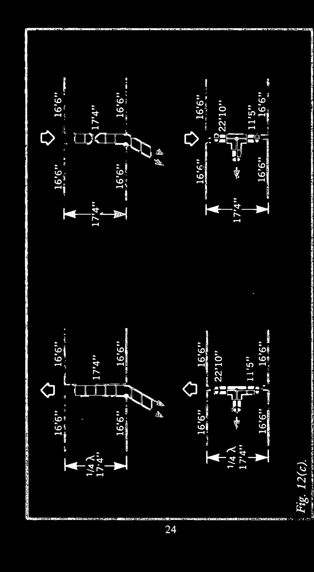
30 if the aerial also displays a reactive component. A somewhat lower SWR can be squeaked out by making the stub more or less than a quarter wavelength. However, in a practical situation with a quality tuner this step is seldom necessary. If you wish to use the coaxial line the special arrangement of Fig.10 using a foreshortened driven element is convenient and really brings down the SWR on the line. Matching adjustments with modern solid-state transmitters can be touchy because you must be careful when a high SWR comes on the line in the tuning process. Thus adjustments initially should be made at as low a power level as possible. If you have a particular interest in aerial experimentation, keep an old low -power vacuum -valve transmitter handy. All early trimming and tuning adjustment to the aerial system can be made before the aerial is connected to your main transmitter. Now only touch-up adjustments are needed. 12. PHASED ARRAY A variety of horizontal phased arrays can be constructed at low cost using wire aerial elements and supports. Two -element end -fire, broadside and collinear styles provide gain and directivity as compared to a single dipole. The end -fire configuration can be spaced for either bidirectional or uni-directional operation as shown in Fig.12. Two half -wavelength dipoles separated by half wavelength and driven out -of -phase, provide a bi-directional good figure -eight pattern obtaining maximum radiation broadside to the aerial wire if properly fed and tuned. Resultant gain can approach approximately 4dB. A fine unidirectional cardidoid pattern is obtained by using quarter -wave spacing and quarter -wave feed. As shown in Fig.12, a quarter -wave section of line is located between dipole to which the transmission line is attached and second dipole. Maximum gain is in the direction of dipole that is fed a lagging 90 degrees, shown by the arrow in Fig.12. The remainder of Fig.12 shows various feed arrangements. In the first set of three, there are three 180 degree end -fire 21


31
.")

32 16'6" Fig. 12(b). 16'6" 16'6" 0 16'6"

33
34 arrangements. The elongated figure -eight pattern is obtained by feeding one dipole and then the second one 180 degrees later with a half -wave section of line. The same results can be obtained by centre -feeding and then transposing one of the quarter -wave segments as shown. The third drawing shows the coaxial feed technique. Note that the center conductor of one feed section goes to the left segment of one dipole while the centre conductor of the other goes to the right segment of the second dipole. As a result the two dipoles are fed out -of -phase. The four remaining drawings demonstrate unidirectional 90 degree feed. Note in the simple parallel feed arrangement that the unidirectional pattern can be shifted by simply transposing the 90 degree feed line that connects between the two dipoles. Unidirectional pattern is always in the direction of the dipole that is fed 90 degrees lagging. When erecting such an aerial you might plan to make it convenient to make such a transposition. It need not be done at the centre as shown but can be accomplished at one of the two dipole feed points. You can do the same thing using T -junction coaxial feed. In of coax from one side of the T -junction to one of the dipoles and a quarter -wave section of feed line to the second. Directivity is determined by proper connection of the inner conductor and shield of the coax segments of the two dipole elements, as shown. Pattern reversal can be obtained simply by transposing either one of the feed lines at the point where it connects to its associated dipole. 13. TWO -ELEMENT BROADSIDE In a horizontal broadside arrangement the two dipoles are placed one above the other for a two -element combination as shown in Fig.13. Horizontal radiation patter is a figure -eight with maxima broadside to the plane of the two dipole elements. Both the horizontal and vertical radiation patterns are shown in Fig.13. The vertical radiation pattern is also a figure - eight and, therefore, does some concentrating of the vertical 25


35 Fig. 13. Broadside Horizontal Vertical 5/8 X
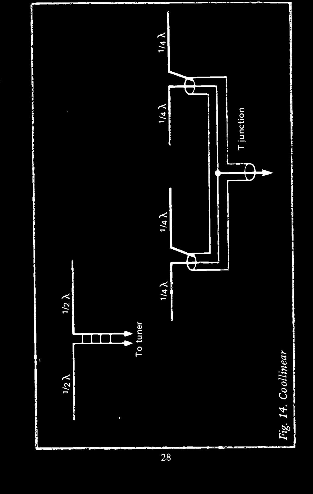
36 radiation at the favored low angles. Dipoles must be fed in phase as shown. In the first feed method there is a half -wave section of line between the bottom and top dipoles. Ordinarily this would produce an outof -phase feed. However, the line is transposed and, therefore, the two dipoles are fed in -phase. Another way of obtaining in - phase feed is to use a centre feed point. Two dipoles can be separated a half wavelength and fed in -phase with this method. Furthermore any separation between the dipoles can be used and in -phase feed will result. If space is available you may wish to try a 5/8 wavelength separation which will result in a further lowering of the vertical radiation angle. 14. COLLINEAR The horizontal collinear is not used too frequently because of space requirements. However, you may wish to experiment with this phase combination on 10 or 15 metres. In the collinear arrangement, Fig.14, two dipole elements are placed end -to -end. However, for good performance it is necessary that the two ends be well separated. The collinear pattern is a sharpened figure -eight that is broadside to the collinear elements. Two basic feed arrangements are shown. In the first one the two half -wave elements can be brought near to each other because a high impedance feed is used. Note that the parallel line connects to the two ends of the separate half -wavelength segments. The open -wire line should have an overall length that is an odd -multiple of a quarter -wavelength so as to present a low impedance at the point where it connects to the tuner. The second feed arrangement is a coaxial line, low - impedance one. Both collinear elements are centre -fed and their respective feed lines are connected to the main coaxial transmission line back to the transmitter by way of a T - junction. 27

37 N 00
38 15. TRIANGLE The triangle is another low-cost aerial that performs extremely well. It is a full -wavelength aerial, like the quad and delta loop, without being so clumsy and subject to weather damage. It is simple, strong and easy to erect as shown in Fig.15. On 40, 80 and 160 metres, where the other full -wavelength aerials are just about impossible, the triangle is an easy assembly. The very centre of the full -wavelength wire is attached at the top of the support mast with an insulator. The two legs fan out and fold back on themselves. The ends are returned to the mast to a dipole connector or other form of insulator. The triangle can then be stretched out on each side using nylon rope and two metal fence posts. You will find it is a very rigid assembly, acting also as partial guying for the mast. It is not necessary that the triangle be equal -sided (equilateral). In some mounting situations it may be advantageous to have the triangle base a different length to the other two sides. The important thing is to have the loop resonate as a full wavelength loop. The base of the triangle need only be 7 to 8 feet above ground to avoid traffic. Aerial impedance is low because the base of the triangle is so near ground. As a result you can make a direct match to coaxial line. The feedpoint at the very centre of the base is accessible using a short stepladder. A starting point for calculating the length of the triangle wire is the equation for a full wavelength in space (Wire Length = 984 fmhz). The proximity of ground may require that the triangle be shortened somewhat below this calculated value after it is erected. It is easy to do so because of the low height of the wire ends. When the base of the aerial is raised as it most likely would be for 10, 15, 20 and even 40 metres, the resonant -wire length may even be greater than the full -wavelength free -space calculation. The aerial resistance increases as the triangle is elevated higher above ground and some form of matching may be needed. If you use open -wire line and a tuner this need not be a consideration. The triangle shows directivity that is broadside to the plane 29

")
39 Metal fence post Fig. 15. Triangle Insulator Plastic clothesline ( X) driven triangle
40 of the triangle. However, omnidirectional performance is quite good but you may wish to orient it in its mounting position for some favored direction. Orientation can be changed very easily from ground level. 16. HIGH -FREQUENCY TRIANGLE A high -frequency triangle can be constructed in the two basic ways shown in Fig.16. A wire triangle can be constructed similar to the low -band version. Insulators and nylon rope are attached to the base angles. It can be pulled out and supported from ground level. The wind will not blow this loop down. An alternative approach is to use self-supporting tubing for the base of the triangle. A thick plastic sheet can be used to support the base elements to the mast. The ends of the tubing can then be linked to the apex of the triangle with wire or additional tubing. Dimensions are given for 20 -metre operation. Total length of wire is 69 feet. Stub matching to coax or parallel line can be used. Using parallel line an aerial tuner is all that is necessary. You will be surprised at the performance of this single -element aerial that can be built at such little cost. 17. TWO -ELEMENT TRIANGLE Reflector and/or director triangles can be added to increase the gain and sensitivity of a triangular configuration in a preferred direction. Spacing between driven triangle and parasitic need only be wavelength, Fig.17. This is an 8th wavelength and can be determined by halving the dimension shown under the quarter -wavelength free -space values given in the dimension charts. In general, wire length should be 5% longer for the reflector and 4% shorter for the director. The driven element itself in close proximity to the parasitic element may require additional length. Often the driven element is dimensioned 1000/f instead of the basic 984/f. Reflector would be 5% longer and director 4% shorter than this new value. 31


41 Aluminium tubing Plastic sheet


42 0.125XA 10( (X) driven Fig. 17. Two-element triangle Parasitic Ref xitic + 5% Director X-5% Reflector stub
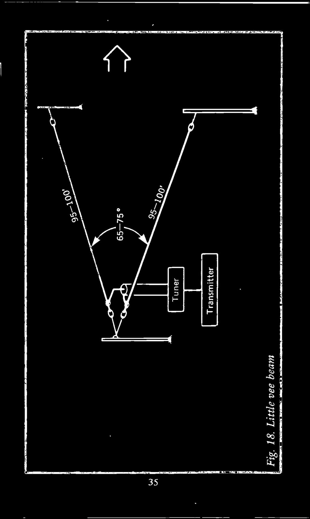
43 In so far as 40, 80 and 160 metre operation is concerned a single additional support mast is required to support the two - element beam. This is indeed a low-cost beam compared to any type of beam that is to be constructed for these bands. Furthermore it is of sound physical structure and not weather - prone. In high -frequency operation it could be supported strongly by two cross members joining the apex of driven element to apex of parasitic, along with another cross beam between the centres of the two bases. The lowness of the 40, 80 and 160 metre triangles means the base of the parasitic is accessible. Thus it could be dimensioned to operate as a director. However, an additional stub could be added as shown in Fig.17 along with a sliding short. With the short positioned at the insulator the parasitic will operate as a director. By sliding it down the stub the proper length, the same element could be operated as a reasonable reflector as well. Additional triangles may be mounted within the triangle of the lowest frequency operation. This is similar to the arrangement employed in multiband quads. A 40 and 80 metre combination is an attractive arrangement. Parasitics could be added in the same manner. 18. LITTLE VEE-BEAM Did you ever wish to experiment with a vee-beam or a rhombic? You thought it was too expensive and you lack the space. Not so. You can put up a short vee-beam or rhombic. Although performance will not duplicate the performance of a very long one, the performance of these short beams will surprise you. A practical, good performing vee-beam is shown in Fig.18. Leg lengths can be feet which corresponds to approximately 3/4 quarter -wavelength on 40 metres. It does fine on 40 metres. Higher -frequency bands have leg wavelengths which exceed 3/4 quarter -wavelength and gain and directivity rise. If you want to send out a good QRP signal in some favored direction on all of these bands the lil'vee-beam 34

44
45 deserves a try. Use open -wire line or good -quality 300 -ohm line and a tuner. The aerial will also load up on 80 metres and give reasonable results. An apex angle between degrees is acceptable. 19. LITTLE RHOMBIC SQUARED The small rhombic of Fig.19 was our good performer for a number of years. You need a mounting space about 100 foot square. The four sides are of the same length and all angles are 90 degrees. It is a perfect square. The rhombic was supported by four 3 -section TV masts, each guyed with nylon rope. Open -wire line and a tuner were used. The aerial is fed at one corner while the opposite corner is left open. This manner of operation establishes a bi-directional pattern. An acceptable uni-directional pattern is obtained by terminating the far corner in a 450 -ohm non -inductive resistor. If you wish to change the aerial pattern on occasion you may do so by moving the wire jumpers that connect the transmission line to any one of the three remaining corners. You must remember to move the two jumper wires to the other two corners when you do so. Halyard arrangements for the various corners are helpful if it is your intent to change directivity. Excellent performance with this small rhombic was obtained on 10, 15, and 40 metres. Acceptable results were obtained on 20 and it would also load for QSO's on 80 metres. If you wish to operate the aerial in an omni-directional fashion you can do so by connecting jumpers at all four corners. Feed the aerial at the centre of one of the sides. 20. QUARTER-WAVE VERTICALS The fundamental vertical aerial is a quarter -wavelength radiator, Fig.20. This is not a true vertical dipole because the physical length of the aerial approximates just one-half the length of a dipole. However, the ground acts as a mirror 36


46 rig. 19. Little rhombic squared
 /AIX")

47 Bolts Fig. 20(a) /AIX verticals 1/4 X vertical Ground support mast Plastic tube
 1 / 4 X Wood 2\" x 3\" U-bolt")

48 l 4. 1 VD Fig. 20(6) 1 / 4 X Wood 2" x 3" U-bolt L., 4.: Wood Dipole 1" x 2" connector or Radials 2" x 3" Metal fence post Ground level
49 quarter -wavelength segment. Ground conditions, in fact, have an influence on performance of the vertical aerial. The mirror segment of the vertical can be ground itself, or it may be a network of wires or tubing that acts as an artificial ground. If placed on the surface of the ground or a few inches below ground, such a low -resistance conducting surface can result in a substantial improvement in aerial performance and uniformity of matching. Often a metallic ground (called a ground plane) is also employed when the quarter wavelength radiator is elevated above this physical ground. In effect, the ground plane brings the ground up to the level of the aerial. An advantage of a vertical aerial is its omni-directional horizontal pattern. It is circular and indicates the radiation of equal level signals in all compass directions. Groups of vertical aerials can be used to obtain a direction pattern when desired. The vertical radiation pattern approximates a half figure -eight. This type of pattern concentrates the radiation at low vertical angles. Little energy is radiated skyward while the favorable low -angle radiation is obtained. Very low-cost verticals can be constructed for 10 and 15 metres using strong pieces of plastic as shown in Fig.20. The same applies to the 20 -metre vertical except that sturdier components are required. In the case of a 40 -meter vertical a wooden support system must be constructed to add additional support for the structure. The first two examples of Fig.20 show how plastic rods and plastic tubes of adequate wall thickness can support a short vertical. The ground rod can be made of the same material as the radiator itself. Holes are drilled through the radiator tubing and the plastic rod. Inserted bolts make the connections to both the radiator and the ground rod. A dipole -to -coax connector can be jumped between the two sections to permit connection of the transmission line. When you can obtain a thick-wall plastic tube the radiator and ground rod can be inserted into the tube as shown in the second example. These two simple arrangements will easily support 10 and 15 metre ground -mounted verticals. The third arrangement shows how a long plastic rod can support a light -weight vertical. The vertical fits over the rod 40
50 and the inner conductor of the coax line connects to one of the holding bolts. A separate ground rod is then connected to the shield of the coax line. No coax connector is needed with this arrangement. The fourth arrangement shows how a whip vertical can be supported on insulators that are mounted on a wooden 1" x 2" or 2" x 3" batten. Inner conductor connects to the whip and the shield to the ground rod. Ground rod should be 6 to 8 feet long. An alternative is to have a shorter ground rod and then solder or bolt at least four radials to the rod, placing them about one or two inches beneath the ground, stretching them out and separating them by approximately 90 degrees. Resonant -length 1/4X radials help in matching and holding up aerial resistance. The fifth scheme shows our favorite mounting arrangement In this arrangement the radiator is U -bolted to a wooden 2" x 3" or 2" x 4" batten. The wooden support is 8 foot long and mounted 3 foot into the ground. A short ground rod is also driven into the ground and has four radials attached to it about an inch and a half below ground level. A dipole -to-coax connector is connected between the bottom U -bolt which supports the radiator and the ground rod. This affords an easy arrangement for connecting the coax line. The radiator can be any size tubing you wish to use for operation on 10, 15 and even 20 metres. If you wish a very sturdy mount, the ground rod can be a metal fence post. Furthermore the section of the 2" x 3" or 2" x 4" batten below the vertical radiator can be bolted to the metal fence post. Separation can be such that the dipole connector can be spanned between radiator U -bolt and the bolt that fastens the wooden support to the metal fence post. In our own application the radiator was a two -section TV mast that would permit operation on either 15 or 20 metres because it could be telescoped. This latter method of assembly was helpful in constructing the vertical beams for 15 and 20 metre operation that will be covered later. For 10 and 15 metre operation, two telescoping sections of smaller diameter tubing were used. Shop around at flea markets and surplus outlets, or any place 41
51 metal tubing is sold, to find a proper combination. 21. TELESCOPING VERTICALS As mentioned in the previous discussion the ability to telescope your vertical permits operation on more than one band. Two 10 -foot telescoping sections provide an easy means of changing over your vertical between 10 and 15 metre operation, Fig.21. A 5 foot and 7 foot section provide an easy means for 10 and 15 metre changeover. To maintain good connections make certain you have a snug fit and a good low -resistance connection where the inner tube leaves the outer tube. If you wish you can drill bolt holes through the two conductors when the two desired resonant lengths are found. 22. UMBRELLA VERTICALS Telescoping TV masts function well as vertical quarter -waves on 40, 80 and 160 metres. A four -section mast can be extended to the approximate 33 feet needed for 40 metre operation. The same size mast can also be used on 80 metres by using aerial wire to extend its resonant length as shown in Fig.22. The four -section mast can be extended to at least 36 feet. Approximately 24 foot lengths of an aerial wire connected to the top can produce 80 -metre resonance. Three lengths of aerial wire can be made to extend away from the top and then supported at ground level using nylon rope. Such an arrangement performs very well and matches ideally to 50 -ohm coaxial line. For best low -angle results use about 9 quarter -wave radials stretched out about 2 inches beneath the surface. Using a 50 -foot telescoping mast fine results were obtained on 160 metres with umbrella aerial wires about 80 foot long. In all of these umbrella installations it may be necessary to adjust the umbrella wire length to find resonance at a preferred frequency. However, performance is quite wideband once you get the resonant length into the band. 42

52 16' max (20) 1 I - T--- 5' 11' max (15; 10' 11' (15) il- 8'2" (10) 7' 1r 4 Fig. 21. Telescoping verticals The base of the vertical was mounted in a wood/cement form and supported by appropriate nylon rope guys. This might be frowned upon as a base insulator. However, it is an economical arrangement and performance was fine. A metallic strap was used to attach the coax connector to the bottom of the vertical while a stiff wire connected the shield side of the coax connector to the radial system. 43


53 Ae-ial wires space 120 Telescoping TV mast Insulator Ground level aw Concrete Radials Fig. 22. Umbrella vertical 23. PHASED VERTICALS The quarter -wavelength verticals described previously can be connected into a variety of directional phased combinations. These combinations produced some surprising DX results despite the fact that they were ground -mounted. Various broadside and end -fire arrangements can be set-up as shown in 44
54 Fig.23. In example (i), the two verticals are fed in -phase from a centre junction to which the transmission line is attached. A T -junction is convenient. The in -phase connection of the two verticals set up a figure -eight broadside pattern. The two - element combination is bi-directional perpendicular to the plane of the two aerials. By feeding the two verticals end -fire, the bi-directional pattern can be along the line of the two aerials as shown in example (ii). In this phasing arrangement the one aerial is fed with the transmission line while the second by a half -wavelength section of line that runs between the first and second verticals. Since your verticals are mounted at ground level it is convenient to change over the directional pattern whenever desired. Example (iii) shows a 90 -degree end -fire connection with the two radiators separated by a quarter -wavelength or 90 degrees. Since the second radiator is fed 90 degrees lagging the first radiator by the 90 degree section of interconnecting line, a cardioid pattern in the direction of the lagging radiator is set-up. This arrangement was described previously in conjunction with the coverage of horizontal phased arrays. Example (iv) shows how the cardioid pattern can be reversed by using an intervening section of coax line that is three-quarter wavelength long. By so doing, radiator 1 lags radiator 2 by 90 degrees. Dimensions are given for 15 metre operation. Four resonant radials are used. In mounting the radials do not permit the radial for radiator 1 to touch the radial of radiator 2. In using two element phased verticals, particularly when you plan them to permit change in the directional pattern, it is advisable to use a tuner to insure optimum transmitter loading. 24. TWO -ELEMENT BROADSIDE Two practical broadside verticals with dimensions for 20 and 40 metre operation are given in Fig.24. In this arrangement centre feed was used to obtain an in -phase feed. It is true that 45


55 c -t.
 End fire, 90 kilf-1/4")
 15 Meter")
56 Fig, 23(h) 12 lags I1, by 90 (iii) End fire, 90 kilf-1/4 1/4 X 10'11" 1/4 X resonant radials 11'2" (iv) 15 Meter end fire


57 1/2 X 34'8" 1/4X 1/4X 16'6" 16'6" T-junction 1/4A radials 16'9" 1/4X radials 16'9" (i) 20 Meter broadside Fig. 24(a) Two-element broadside

 40 Meter")
58 Fig. 24(b) i 1/2 X 68'4" 1/4 X 32'4" 1/4 X 37'4" 1/4 A radials 32'8" Transmitter I Tuner 1/4X radials 32'8" (ii) 40 Meter broadside
59 matching is not ideal but reasonable results were obtained using a tuner ahead of the transmitter. The use of resonant radials do keep up the impedance of each of the quarter -wave verticals. Respective radials of the two verticals should not touch each other. If you are concerned about the matching at the T -junction 3/4 wavelength sections of line can be used between each radiator and the T -junction. Use 70 -ohm line for these two segments. The coaxial line back to the transmitter should be 50 -ohm line. 25. END -FIRE BROADSIDE COMBINE The arrangement of Fig.25 demonstrates how to construct individual phasing loops that can be inserted to alter the radiation pattern of two quarter -wavelength verticals separated by something less than a half -wavelength. Good broadside and end -fire 180 degree patterns are obtained, while the end -fire 90 degree pattern is acceptable but not ideal. Example (i) shows the broadside configuration with dimensions' given for 15 metre operation. Proper lengths of feed cable after the T - junction permit end -fire 90 degree unidirectional operation. Compare (ii) and (iii) to show how the unidirectional pattern can be reversed using the same pre-cut feed cable. Example (iv) shows the end -fire 180 degree cabling. This combination feeds the two verticals out -of -phase and a bi-directional pattern is set up in line with the two verticals. Recall that the broadside pattern of example (i) is perpendicular to the plane of the two verticals. Some helpful dimension tables follow. Have a good time with your antenna experiments! 50

 End-fire 90.111111. (iv) End-fire 180' Fig.")
60 (i) 15 Meter broadside 1.4* -_<1/2 X_Iopi 15'3" 1/4 A 10'11" 7'71/2" 7'71/2" 1/4 A 10'11" 1/4 A radials 11'2" (ii) End-fire 90* 1/4 A radials 11'2" (iii) End-fire (iv) End-fire 180' Fig. 25. End-fire broadside combine 51
61 DIMENSION TABLES The following tables supply important data useful in the practical dimensioning in feet of aerial systems 2 through 160 metres including the new WARC bands. Dimensions are given for the UK 4 metre band and the USA 6 metre band. A full range of dimensions are given for the 40 and 80 metre bands to accommodate the UK bands as well as the wider USA bands. Column 1 gives the frequency in MHz. Columns 2 and 3 show the Y4X and la free space dimensions in feet. This data is helpful in spacing beam elements, both parasitic and phased arrays. Column 4 is the length, in feet, of each quarter -wave side of a dipole. Column 5 is the length, in feet, of a threequarter side of a 3/2 wavelength aerial. Columns 6 and 7 show the parasitic reflector and director length in feet for beam aerials. Column 8 gives the dimensions, in feet, for the full - wave triangle. Columns 9 and 10 show the length, in feet, of %X and %X segments for the common 0.66 velocity factor coaxial line. In using phasing and matching stubs made of coaxial line the velocity factor must be considered. 53
62 Freq. MHz 2 YiX ft. 3 ft. 4 Dipole Aft. 5 ft. 6 Refl. ft. 7 Dir. ft. 8 ft. 9 Y1X Ydk METRES
63 METRES LA 3.62 (..., ' ,
64 0" Freq. MHz 2 XIX ft. 3 14X ft. 4 Dipole Wt. 5 34X ft. 6 Refl. ft. 7 Dir. ft. 8 Tri. ft. 10 %XX ' METRES
65 METRES :
66 ( Freq. MHz 2 %X ft. 3 X ft. 4 Dipole 'aft. 5 3/X ft. 6 Refl. ft. 7 Dir. ft. 8 TrL ft. 9 YIX 'W\ METRES METRES I
67 METRES METRES I
68 rn 1 Freq. MHz 2 %X ft. 3 %X ft. 4 Dipole %Vt. 5 %? ft. 6 Ref 1. ft. 7 Dir. ft. 9 Tri. ft. 9 3 X X METRES NEW WARC BANDS 30 METRES
69 METRES METRES :72 9:
70 LENGTH CONVERSION TABLE The table below is an aid in converting feet in decimals to decimal inches and then to practical tape -lengths. For example, an element that is 31.5 feet is 31 feet 6 inches. An aerial which is feet is approximately 12' 41/4". These are not exact values but are practical in terms of cutting a length with a tape measure. Inches equals decimal part of a foot times 12. Decimal ft. Decimal in. Tape in % / / / % / k / / / / / % / / k 62

 Open wire (450a) Ribbon cable")
71 EQUATIONS 1/4X Free Space = 246/fmHz 1/2X Free Space = //fivifmilzz 1/4X Dipole = 3/4X Dipole = 710/fmHz Reflector = 492/fmHz Director = 450/fmHz Triangle = 984/fmHz %X x 0.66VF = 162/fmHz 1/2X x 0.66VF = 324/fMHz TYPES OF CABLES Coaxial (RG 59U -58U) Open wire (450a) Ribbon cable (30011) Fig. 26. Illustration of types of cables 63
72 ALSO OF INTEREST BP105: AERIAL PROJECTS R. A.Penfold Whether you have built a very simple short wave receiver or have purchased a most sophisticated piece of equipment, the performance you achieve will ultimately depend on the aerial to which your set is connected. The subject of aerials is vast but in this book the author has considered practical aerial designs, including active, loop and ferrite aerials which give good performances and are relatively simple and inexpensive to build. The complex theory and mathematics of aerial design have been avoided. Also included are constructional details of a number of aerial accessories including a preselector, attenuator, filters and tuning unit. 96 pages ' Z1.95
73 Please note overleaf is a list of other titles that are available in our range of Radio, Electronics and Computer Books. These should be available from all good Booksellers, Radio Component Dealers and Mail Order Companies. However, should you experience difficulty in obtaining any title in your area, then please write directly to the publisher enclosing payment to cover the cost of the book plus adequate postage. If you would like a complete catalogue of our entire range of Radio, Electronics and Computer Books then please send a Stamped Addressed Envelope to: BERNARD BABANI (publishing) LTD THE GRAMPIANS SHEPHERDS BUSH ROAD LONDON W6 7NF ENGLAND
74 160 Coil Design and Construction Manual Beginners Guide to Building Electronic Projects BP28 Resistor Selection Handboox E1.96 BP36 E Circuits Using Germanium Silicon & Zener Diodes BP37 50 Projects Using Relays, SCRs and TRIACs 1.95 BP39 50 (FET) Field Effect Transistor Projects P42 E Simple LED Circuits BP44 IC 555 Projects Et% BP48 E2.95 Electronic Projects for Beginners BP49 Popular Electronic Projects 1.95 BP Practical Electron'. Caleuhrions & Formulae 13P56 E3.95 Electronic Security Devices BP74 Electronic Music Projects 2.95 BP76 Power Supply Projects E2.95 BP Practical Computer Experiments eno 1.75 Popular Electronic Circuits - Book 1 BP84 Digital IC Projects 2.95 ens 1.95 International Transistor Equ'valents Guide 8P Simple LED Circuits- Book 2 ens How to Use Op -amps 1.95 BP30 Audio Projects 2.95 BP Electronics Simplified- Crystal Set Construction EIP94 E1.75 Electronic Projects for Cars and Boats B P35 Model Railway Projects 1.95 BP97 IC Projects for Beginners P Popular Electronic Circuits - Book 2 B P39 Mini -matrix Board Projects 2.95 BP105 Aerial Projects 2.50 BP So'dories, Breadboard Projects - Book 1 BP110 How to Get Your Electronic Projects Working 2.95 BP111 Audio E2.95 BP115 E3.95 The Pre -computer Book BP Practical Electronic Building 3locks -Book 2 BP How to Design and Make Yoar Own PCB's BP Audio Amplifier Construction BP Simple Amateur Band Aerials BP BASIC & PASCAL in Parallel BP Micro Interfacing Circuits - Book 1 P Micro Interfacing Circuits - Book 2 P132 E Simple SW Broadcast Band Aerials P136 E Simple Indoor and Window Aerials P BASIC & FORTRAN in Paralle P138 Et% BASIC & FORTH in Parallel P144 E1.95 Further Practical Electronics Calculations & Formulae P Simple Tropical and MW Band Aerials P146 E1.75 The Pre -BASIC Book P An Introduction to 6502 Machine Code P Computer Terminology Explained P Easy Add-on Projects for Amstrad CPC & MSS Computers P A TV-Okers Handbook (Revised Edition) P177 E5.95 An Introduction to Computer Communications P179 E2.95 Electronic Circuits for the Computer Control of Robots P182 MIDI Projects 2.95 P An Introduction to Assembly Language P187 E2.95 A Practical Reference Guide to Word Processing on the Amstrad PCW8256 & PCW8512 P More Advanced Electronic Security Projects P192 E2.95 More Advanced Power Supply Projects P LOGO for Beginners P196 E2.95 BASIC & LOGO in Parallel P197 E2.96 An Introduction to the Amstrad PC's P198 E6.95 An Introduction to Antenna Theory P A Concise Introduction to GEM P232 E2.95 A Concise Introduction to MS-DOS P Electronic Hobbyists Handbook P Getting the Most From Your Multimeter 2.95 P240 Remote Control Handbook P243 E3.95 BBC BASIC86 on the Amstrad PC's & IBM Compatibles- Book 1: Language P BBC BASIC86 on the Amstrad PC's & IBM Compatibles - Book 2: Graphics E3.95 and Disk Files P245 Digital Audio Projects P Musical Applications of the Atari ST's P More Advanced MIDI Projects P248 E2.95 Test Equipment Construction P More Advanced Test Equipment Construction P250 E3.50 Programming in FORTRAN P251 Computer Hobbyists Handbook 5.95 P254 From Atoms to Amperes E3.50 P255 International Radio Stations Guide (Revised 1991/92 Edition) P An Introduction to Loudspeakers & Enclosure Design E2.95 P257 An Introduction to Amateur Radio E3.50 P258 Learning to Program in C (Revised Edition) P259 E4.95 A Concise Introduction to UNIX P260 E2.95 A Concise Introduction to OS/2 P A Concise Introduction to Lot., (Revised Edition) 3.95
75 BP262 A Concise Introduction to Wordperfect (Revised Edition) BP264 A Concise Advanced User's Guide to MS -D05 (Revised Edition) BP265 More Advanced Uses of the Multimeter BP266 Electronic Modules and Systems for Beginners BP267 How to Use Oscilloscopes & Other Test Equipment BP269 An Introduction to Desktop Publishing BP270 A Concise Introduction to Symphony BP271 How to Expand, Modernise & Repair PC's & Compatibles BP272 Interfacing PCs and Compatibles BP273 Practical Electronic Sensors BP274 A Concise Introduction to SuperCalc5 BP275 Simple Short Wave Receiver Construction BP276 Short Wave Superhet Receiver Construction BP277 High Power Audio Amplifier Construction BP278 Experimental Antenna Topics BP279 A Concise Introduction to Excel BP280 Getting the Most From Your PC's Hard Disk BP281 An Introduction to VHF/UHF for Radio Amateurs BP282 Understanding PC Specifications 8E283 A Concise Introduction to SmartWare II BP284 Programming in QuickBASIC A Beginners Guide to Modern Electronic Components BP286 A Reference Guide to Basic Electronics Terms BP287 A Reference Guide to Practical Electronics Terms BP288 A Concise Introduction to Windows3.0 BP290 An Introduction to Amateur Communications Satellite BP291 A Concise Introduction to Ventura BP292 Public Address Loudspeaker Systems BP293 An Introduction to Radio Wave Propagation BP294 A Concise Introduction to Microsoft Works BP295 A Concise Introduction to Word for Windows BP297 Loudspeakers for Musicians BP298 A Concise Introduction to the Mac System & Finder Practical Electronic Filters BP300 Setting Up An Amateur Radio Station BP301 Antennas for VHF and UHF SF302 A Concise Users Guide to Lotus 14-3 Release 3.1 BP303 Understanding PC Software BP304 Projects for Radio Amateurs and SWLs BP305 learning CAD with AutoSketch for Windows BP306 A Concise Introduction to Ami Pro 3 BP307 A Concise Introduction to QuarkXPress BP308 A Concise Introduction to Word 5.1 on the Macintosh BP309 Preamplifier and Filter Circuits BP310 Acoustic Feedback - How to Avoid It BP311 An Introduction to Scanners and Scanning BP312 An Introduction to Microwaves BP313 A Concise Introduction to Sage BP314 A Concise Introduction to Quattro Pro BP315 An Introduction to the Electromagnetic Wave BP316 Practical Electronic Design Data BP317 Practical Electronic Timing BP318 A Concise User's Guide to MS-DOS Making MS-DOS Work for You BP320 Electronic Projects for Your PC BP321 Circuit Source- Book Circuit Source - Book 2 BP323 How to Choose a Small Business Computer System BP324 The Art of Soldering BP325 A Concise Users Guide to Windows3.1 BP326 The Electronics of Satellite Communications BP327 MS-DOS One Step at a Time BP328 Sage Explained BP329 Electronic Music Learning Projects BP330 A Concise User's Guide to Lotus Release 2.4 BP331 A Beginners Guide to MIDI BP332 A Beginners Guide to TTL Digital ICs BP333 A Beginners Guide to CMOS Digital ICs BP334 Magic Electronic Projects BP335 Operational Amplifier User's Handbook BP336 A Concise User's Guide to Lotus Release 3.4 BP337 A Concise Users Guide to Lotus for Windows BP338 A Concise Introduction to Word for Windows A Concise Introduction to Wordperfect 5.2 for Windows BP340 A Concise Introduction to dbase V 8P341 A Concise Users Guide to MS-DOS 6 BP342 A Conciser Users Guide to Lotus Improv E E395 E E395 E E3.95 E3.95 E E495 E495 E3.95 E5.95 1E5.95 E3.95 E3.95 E3.95 E3.95 E E3.95 E4.95 E E E E E E E4.95 E4.95 E E E E5.95


76 25 Simple Amateur Band Aerials This concise book describes how to build 25 amateur band aerials that are simple and inexpensive to construct and perform well. The designs start with the simple dipole and proceed to beam, triangle and even a mini -rhombic made from four TV masts and about 400 feet of wire. After the aerial discussion you will find a complete set of dimension tables that will help you spot an aerial on a particular frequency. Dimensions are given for various style aerials and other data needed for spacing and cutting phasing lengths. Also included are dimensions for the new WARC bands. ISBN =X (!;0= CO --
Chapter 6 Antenna Basics. Dipoles, Ground-planes, and Wires Directional Antennas Feed Lines
 Chapter 6 Antenna Basics Dipoles, Ground-planes, and Wires Directional Antennas Feed Lines Some General Rules Bigger is better. (Most of the time) Higher is better. (Most of the time) Lower SWR is better.
CHAPTER 8 ANTENNAS 1
 CHAPTER 8 ANTENNAS 1 2 Antennas A good antenna works A bad antenna is a waste of time & money Antenna systems can be very inexpensive and simple They can also be very expensive 3 Antenna Considerations
ANTENNAS. I will mostly be talking about transmission. Keep in mind though, whatever is said about transmission is true of reception.
 Reading 37 Ron Bertrand VK2DQ http://www.radioelectronicschool.com ANTENNAS The purpose of an antenna is to receive and/or transmit electromagnetic radiation. When the antenna is not connected directly
UNIT Write short notes on travelling wave antenna? Ans: Travelling Wave Antenna
 UNIT 4 1. Write short notes on travelling wave antenna? Travelling Wave Antenna Travelling wave or non-resonant or aperiodic antennas are those antennas in which there is no reflected wave i.e., standing
4 Antennas as an essential part of any radio station
 4 Antennas as an essential part of any radio station 4.1 Choosing an antenna Communicators quickly learn two antenna truths: Any antenna is better than no antenna. Time, effort and money invested in the
L. B. Cebik, W4RNL. Basic Transmission Line Properties
 L. B. Cebik, W4RNL In the course of developing this collection of notes, I have had occasion to use and to refer to both series and parallel coaxial cable assemblies. Perhaps a few notes specifically devoted
4/29/2012. General Class Element 3 Course Presentation. Ant Antennas as. Subelement G9. 4 Exam Questions, 4 Groups
 General Class Element 3 Course Presentation ti ELEMENT 3 SUB ELEMENTS General Licensing Class Subelement G9 Antennas and Feedlines 4 Exam Questions, 4 Groups G1 Commission s Rules G2 Operating Procedures
ANTENNAS Wires, Verticals and Arrays
 ANTENNAS Wires, Verticals and Arrays Presented by Pete Rimmel N8PR 2 1 Tonight we are going to talk about antennas. Anything that will conduct electricity can be made to radiate RF can be called an antenna.
General License Class Chapter 6 - Antennas. Bob KA9BHD Eric K9VIC
 General License Class Chapter 6 - Antennas Bob KA9BHD Eric K9VIC Learning Objectives Teach you enough to get all the antenna questions right during the VE Session Learn a few things from you about antennas
Coming next: Wireless antennas for beginners
 Coming next: Wireless antennas for beginners In other rooms: Logbook of the World (Sussex Suite) SO2R contest operation (Stable Suite) Wires for your wireless: Simple wire antennas for beginners dominic
Design of a Delta Loop September 26, 2016
 Design of a Delta Loop September 26, 2016 by K0ZR Introduction Why a Delta loop? A Delta loop can be made to radiate a horizontal or vertically polarized signal. In most cases one chooses the vertical
Cray Valley Radio Society. Real Life Wire Antennas
 Cray Valley Radio Society Real Life Wire Antennas 1 The basic dipole The size of an antenna is determined by the wavelength of operation In free space: ~3x10 8 m/s Frequency x Wavelength = Speed of Light,
Technician Licensing Class. Antennas
 Technician Licensing Class Antennas Antennas A simple dipole mounted so the conductor is parallel to the Earth's surface is a horizontally polarized antenna. T9A3 Polarization is referenced to the Earth
The Fabulous Dipole. Ham Radio s Most Versatile Antenna
 The Fabulous Dipole Ham Radio s Most Versatile Antenna 1 What is a Dipole? Gets its name from its two halves One leg on each side of center Each leg is the same length It s a balanced antenna The voltages
BUILD A HIGH PERFORMANCE TWO ELEMENT TRI-BAND CUBICAL QUAD. By Bob Rosier K4OCE INTRODUCTION THEORY AND GENERAL INFORMATION
 BUILD A HIGH PERFORMANCE TWO ELEMENT TRI-BAND CUBICAL QUAD INTRODUCTION By Bob Rosier K4OCE Lots of DX can be worked with a dipole at the QRP level, however, a beam will obviously give you additional gain
Basic Wire Antennas. Part II: Loops and Verticals
 Basic Wire Antennas Part II: Loops and Verticals A loop antenna is composed of a single loop of wire, greater than a half wavelength long. The loop does not have to be any particular shape. RF power can
A short, off-center fed dipole for 40 m and 20 m by Daniel Marks, KW4TI
 A short, off-center fed dipole for 40 m and 20 m by Daniel Marks, KW4TI Version 2017-Nov-7 Abstract: This antenna is a 20 to 25 foot long (6.0 m to 7.6 m) off-center fed dipole antenna for the 20 m and
Least understood topics by most HAMs RF Safety Ground Antennas Matching & Feed Lines
 Least understood topics by most HAMs RF Safety Ground Antennas Matching & Feed Lines Remember this question from the General License Exam? G0A03 (D) How can you determine that your station complies with
Beams and Directional Antennas
 Beams and Directional Antennas The Horizontal Dipole Our discussion in this chapter is about the more conventional horizontal dipole and the simplified theory behind dipole based designs. For clarity,
Weekend Antennas No. 5 The "Compact Quad" Multiband Antenna
 Weekend Antennas No. 5 The "Compact Quad" Multiband Antenna When I relocated to Johannesburg I needed a new multiband HF antenna. Since I was staying in a rented house a tower was out of the question,
MFJ-941E Versa Tuner II GENERAL INFORMATION:
 GENERAL INFORMATION: MFJ VERSA TUNER II The MFJ-941E is designed to match virtually any transmitter to any antenna, including dipoles, inverted-vees, verticals, mobile whips, beams, random wires, and others
Nick Garner N3WG and George Zafiropoulos KJ6VU
 Nick Garner N3WG and George Zafiropoulos KJ6VU Introduction Over the last few years, there has been a significant increase in the number of radio amateurs interested in portable operating. This is due
A Triangle for the Short Vertical
 1 von 11 03.03.2015 12:37 A Triangle for the Short Vertical Operator L. B. Cebik, W4RNL Last month, I described a triangle array of three full-size vertical dipoles for 40 meters (with 30 meters as a bonus).
Emergency Antennas. Presented by Ham Hilliard W4GMM
 Emergency Antennas Presented by Ham Hilliard W4GMM Dipole antenna Vertical antenna Random wire antenna Dipole antenna The half wave dipole antenna consists of a conductive wire or rod that is half the
The first thing to realize is that there are two types of baluns: Current Baluns and Voltage Baluns.
 Choosing the Correct Balun By Tom, W8JI General Info on Baluns Balun is an acronym for BALanced to UNbalanced, which describes certain circuit behavior in a transmission line, source or load. Most communications
Ten-Tec Model 3402 and 3403 Broadband Antennas Installation and Operation Manual PN 74393
 1. Introduction Ten-Tec Model 3402 and 3403 Broadband Antennas Installation and Operation Manual PN 74393 The Ten-Tec Model 3402 Broadband Terminated Vee Beam Antenna offers continuous coverage between
Last year I described several Low Band RX antennas that would enable you to hear DX stations on 160, 80 and 40M. This will show you how to build
 Last year I described several Low Band RX antennas that would enable you to hear DX stations on 160, 80 and 40M. This will show you how to build transmit antennas that will help you break the pileups!
Technician License Course Chapter 4. Lesson Plan Module 9 Antenna Fundamentals, Feed Lines & SWR
 Technician License Course Chapter 4 Lesson Plan Module 9 Antenna Fundamentals, Feed Lines & SWR The Antenna System Antenna: Transforms current into radio waves (transmit) and vice versa (receive). Feed
Other Arrays CHAPTER 12
 CHAPTER 12 Other Arrays Chapter 11 on phased arrays only covered arrays made of vertical (omnidirectional) radiators. You can, of course, design phased arrays using elements that, by themselves, already
A multi-band wire antenna that performs exceptionally well even though it confounds antenna modeling software
 A multi-band wire antenna that performs exceptionally well even though it confounds antenna modeling software Click FAQ to read a list of frequently asked questions and answers about the W5GI Mystery Antenna.
Technician Licensing Class T9
 Technician Licensing Class T9 Amateur Radio Course Monroe EMS Building Monroe, Utah January 11/18, 2014 January 22, 2014 Testing Session Valid dates: July 1, 2010 June 30, 2014 Amateur Radio Technician
Half-Wave Dipole. Radiation Resistance. Antenna Efficiency
 Antennas Simple Antennas Isotropic radiator is the simplest antenna mathematically Radiates all the power supplied to it, equally in all directions Theoretical only, can t be built Useful as a reference:
Antennas and Propagation Chapters T4, G7, G8 Antenna Fundamentals, More Antenna Types, Feed lines and Measurements, Propagation
 Antennas and Propagation Chapters T4, G7, G8 Antenna Fundamentals, More Antenna Types, Feed lines and Measurements, Propagation =============================================================== Antenna Fundamentals
Newcomers And Elmers Net: Wire Antennas Robert AK3Q
 Newcomers And Elmers Net: Wire Antennas 02-07-16 Robert AK3Q Wire antennas represent one of the greatest values in the radio hobby world. For less than the cost of a good meal out on the town you can buy
Table of Contents. MFJ-1778 G5RV Multiband Antenna
 Table of Contents MFJ-1778 G5RV Multiband Antenna Introduction... 1 Theory Of Operation... 1 80 meter band:... 1 40 meter band:... 1 30 meter band:... 2 20 meter band:... 2 17 meter band:... 2 15 meter
Portable or Emergency VHF Antennas Paul R. Jorgenson KE7HR
 For emergency or public service events it is often necessary to have more antenna than the rubber duck on your handheld VHF radio. Nearly ANY external antenna will provide more coverage for your handheld
Technician License. Course
 Technician License Course Technician License Course Chapter 4 Lesson Plan Module - 10 Practical Antennas The Dipole Most basic antenna The Dipole Most basic antenna The Dipole Total length is ½ wavelength
MFJ-219/219N 440 MHz UHF SWR Analyzer TABLE OF CONTENTS
 MFJ-219/219N 440 MHz UHF SWR Analyzer TABLE OF CONTENTS Introduction...2 Powering The MFJ-219/219N...3 Battery Installation...3 Operation Of The MFJ-219/219N...4 SWR and the MFJ-219/219N...4 Measuring
1) Transmission Line Transformer a. First appeared on the scene in 1944 in a paper by George Guanella as a transmission line transformer, the 1:1
 Transmission Line Transformer a. First appeared on the scene in 1944 in a paper by George Guanella as a transmission line transformer, the 1:1") 1) Transmission Line Transformer a. First appeared on the scene in 1944 in a paper by George Guanella as a transmission line transformer, the 1:1 Guanella Balun is the basic building Balun building block.
1) Transmission Line Transformer a. First appeared on the scene in 1944 in a paper by George Guanella as a transmission line transformer, the 1:1 Guanella Balun is the basic building Balun building block.
4/25/2012. Supplement T9. 2 Exam Questions, 2 Groups. Amateur Radio Technician Class T9A: T9A: T9A: T9A:
 Amateur Radio Technician Class Element 2 Course Presentation ti ELEMENT 2 SUB-ELEMENTS Technician Licensing Class Supplement T9 Antennas, Feedlines 2 Exam Questions, 2 Groups T1 - FCC Rules, descriptions
Antennas Demystified Antennas in Emergency Communications. Scott Honaker N7SS
 Antennas Demystified Antennas in Emergency Communications Scott Honaker N7SS Importance of Antennas Antennas are more important than the radio A $5000 TV with rabbit ears will have a lousy picture Antennas
Adjust Antenna Tuners Antenna Measurements Capacitor Measurement Measure Feed Point Impedance Measure Ground Loss Inductor Measurement
 The Micro908 antenna analyzer is an extremely useful instrument to have around the ham shack or homebrewer s workbench. This section describes the basic uses, as well as some advanced techniques for which
AV-12AVQ Triband HF Vertical 10, 15, 20-Meter INSTRUCTION MANUAL
 308 Industrial Park Starkville, MS 39759 USA Ph: (662) 323-9538 FAX: (662) 323-6551 AV-12AVQ Triband HF Vertical 10, 15, 20-Meter INSTRUCTION MANUAL General Description This vertical antenna is designed
Installation Instructions Hustler 6-BTV Trap Vertical
 Installation Instructions Hustler 6-BTV Trap Vertical ASSEMBLY 1. Check the package contents against the parts list on page 2. 2. WARNING. Installation of this product near power lines is dangerous. For
"Natural" Antennas. Mr. Robert Marcus, PE, NCE Dr. Bruce C. Gabrielson, NCE. Security Engineering Services, Inc. PO Box 550 Chesapeake Beach, MD 20732
 Published and presented: AFCEA TEMPEST Training Course, Burke, VA, 1992 Introduction "Natural" Antennas Mr. Robert Marcus, PE, NCE Dr. Bruce C. Gabrielson, NCE Security Engineering Services, Inc. PO Box
FCC Technician License Course
 FCC Technician License Course 2014-2018 FCC Element 2 Technician Class Question Pool Presented by: Tamiami Amateur Radio Club (TARC) WELCOME To the third of 4, 3-hour classes presented by TARC to prepare
MFJ-949E. tuner antenowy skrzynka antenowa. Instrukcja obsługi. importer:
 Instrukcja obsługi MFJ-949E tuner antenowy skrzynka antenowa importer: PRO-FIT Centrum Radiokomunikacji InRadio ul. Puszkina 80 92-516 Łódź tel: 42 649 28 28 e-mail: biuro@inradio.pl www.inradio.pl MFJ-949E
Installation Instructions Hustler 6-BTV Trap Vertical
 Installation Instructions Hustler 6-BTV Trap Vertical ASSEMBLY 1. Check the package contents against the parts list on page 2. 2. WARNING. Installation of this product near power lines is dangerous. For
Model VB-23FM 2-Meter 3-Element Beam
 308 Industrial Park Road Starkville, MS 39759 USA Ph: (662) 323-9538 FAX: (662) Model VB-23FM 2-Meter 3-Element Beam [ INSTRUCTION MANUAL Figure 1 Overall View and Boom Detail GENERAL DESCRIPTION This
Technician License. Course
 Technician License Course Technician License Course Chapter 4 Lesson Plan Module - 9 Antenna Fundamentals Feed Lines & SWR The Antenna System The Antenna System Antenna: Transforms current into radio waves
G7FEK LIMITED SPACE ANTENNA
 80, 40, 30, 17, 15, 12 m see tet for 20 & 10m operation For 20m operation add red wire 16.5ft ( 5.1m) 24 ft (7.4m) Copyright 2009 G7FEK During the 1980s Mike, G7FEK, described a limited space antenna suitable
Technician License Course Chapter 4. Lesson Plan Module 10 Practical Antennas
 Technician License Course Chapter 4 Lesson Plan Module 10 Practical Antennas The Dipole Most basic antenna Total length is ½ wavelength (½ λ) Usual construction: Two equal halves of wire, rod, or tubing
Working Bouvet with the Innovative and Cheap N6MW, Bill Wortman
 Working Bouvet with the Innovative and Cheap N6MW, Bill Wortman Trying to work the upcoming early 2018 Bouvet Dxpedition for an all time new one (ATNO as we say) is a serious challenge for those with only
MFJ-969 Versa Tuner II Instruction Manual
 MFJ-969 Versa Tuner II Instruction Manual General Information The MFJ-969 is a 300 watt RF output power antenna tuner that will match any transmitter or transceiver to virtually any antenna. Peak or average
Antennas 101 Don t Be a 0.97 db Weakling! Ward Silver NØAX
 Antennas 101 Don t Be a 0.97 db Weakling! Ward Silver NØAX Overview Antennas 101 2 Overview Basic Antennas: Ground Plane / Dipole How Gain and Nulls are Formed How Phased Arrays Work How Yagis Work (simplified)
Amateur Extra Manual Chapter 9.4 Transmission Lines
 9.4 TRANSMISSION LINES (page 9-31) WAVELENGTH IN A FEED LINE (page 9-31) VELOCITY OF PROPAGATION (page 9-32) Speed of Wave in a Transmission Line VF = Velocity Factor = Speed of Light in a Vacuum Question
Transmission lines carry RF
 Transmission Line asics Technical techniques: primer for transmission lines Part I n understanding of transmission lines and tips on using them as transformers and filters can help techs properly configure
25 Simple Tropical. and M.W. Band. Aerials E M. NOLL
 25 Simple Tropical and M.W. Band Aerials E M. NOLL 25 SIMPLE TROPICAL AND M.W. BAND AERIALS by E. M. NOLL BERNARD BABANI (publishing) LTD THE GRAMPIANS SHEPHERDS BUSH ROAD LONDON W6 7NF ENGLAND PLEASE
Antenna Design for FM-02
 Antenna Design for FM-02 I recently received my FM-02 FM transmitter which I purchased from WLC. I researched the forum on what antennas where being used by the DIY community and found a nice write-up
Yagi beam antennas CHAPTER 10 COMPOSITION OF A BEAM ANTENNA _
 CHAPTER 10 Yagi beam antennas The Yagi beam antenna (more correctly, the Yagi Uda antenna, after both of the designers of Tohoku University in Japan 1926) is unidirectional. It can be vertically polarized
TABLE OF CONTENTS. 2.2 Monopoles Characteristics of a l/4 Monopole Folded Monopoles. 2.3 Bibliography. Antenna Fundamentals 1-1
 TABLE OF CONTENTS 2.1 Dipoles 2.1.1 Radiation Patterns 2.1.2 Effects of Conductor Diameter 2.1.3 Feed Point Impedance 2.1.4 Effect of Frequency on Radiation Pattern 2.1.5 Folded Dipoles 2.1.6 Vertical
Antenna? What s That? Chet Thayer WA3I
 Antenna? What s That? Chet Thayer WA3I Space: The Final Frontier Empty Space (-Time) Four dimensional region that holds everything Is Permeable : It requires energy to set up a magnetic field within it.
Traveling Wave Antennas
 Traveling Wave Antennas Antennas with open-ended wires where the current must go to zero (dipoles, monopoles, etc.) can be characterized as standing wave antennas or resonant antennas. The current on these
BUILD A SHORTWAVE ANTENNA "The Search For The Perfect Shortwave Antenna" by N4UJW Webmaster Hamuniverse.com
 BUILD A SHORTWAVE ANTENNA "The Search For The Perfect Shortwave Antenna" by N4UJW Webmaster Hamuniverse.com THE MULTIBAND LONG WIRE SHORTWAVE ANTENNA A Much Better But More Complicated Antenna This antenna
A 2 ELEMENT 30 METER PARASITIC VERTICAL ARRAY PROJECT
 A 2 ELEMENT 30 METER PARASITIC VERTICAL ARRAY PROJECT Having killed off the 5B-DXCC purely using LOTW, it was time for the addition of a new band. 30 meters was selected based on lack of sunspots and a
The DBJ-1: A VHF-UHF Dual-Band J-Pole
 By Edison Fong, WB6IQN The DBJ-1: A VHF-UHF Dual-Band J-Pole Searching for an inexpensive, high-performance dual-band base antenna for VHF and UHF? Build a simple antenna that uses a single feed line for
The J-Pole Antenna. Gary Wescom
 The J-Pole Antenna Gary Wescom - 2018 Much has been written about the J-Pole antenna. A simple Google search will net days worth of reading material on the subject. That would tend to indicate this paper
PAC-12 Kit Contents. Tools Needed Soldering iron Phillips screwdriver Wire stripper Wrenches, 7/16 and 1/2 Terminal crimp tool Pliers Solder
 PAC-2 Kit Contents Part Quantity Screws: 8/32 x 3/8 Screws: 8-32 x 5/6 Screw: 8-32 x /4 #8 internal tooth washers #8 solder lug ring terminals Bolt: Aluminum, /4-20 x.5 /4 internal tooth washer Nut: Aluminum
Chapter 9 Antennas and Feedlines
 Chapter 9 Antennas and Feedlines Basics of Antennas Antenna Radiation Patterns. Graphical representation of spatial distribution of energy around an antenna. 3D = Full representation. 2D = Slice through
TWO METER HOMEMADE SLIM JIM ANTENNA
 Gordon Gibby July 15, 2016 TWO METER HOMEMADE SLIM JIM ANTENNA WIRE: Start with a piece of solid #14 AWG household wire approximately 3 yards and 9 inches long (117 ) (It is easier to be a couple inches
MFJ-2389 Compact 8 Band Vertical
 MFJ-2389 Compact 8 Band Vertical The MFJ-2389 is an 8 band compact vertical that is designed to operate on 80, 40, 20, 15, 10, 6, 2M, and 70CM bands. The antenna will handle 200W PEP or 50W CW HF or 150W
L. B. Cebik, W4RNL. 1. You want to get on 160 meters for the first time (or perhaps, for the first time in a long time).
.") L. B. Cebik, W4RNL The following notes rest on a small set of assumptions. 1. You want to get on 160 meters for the first time (or perhaps, for the first time in a long time). 2. You want to set up the
L. B. Cebik, W4RNL The following notes rest on a small set of assumptions. 1. You want to get on 160 meters for the first time (or perhaps, for the first time in a long time). 2. You want to set up the
HFp. User s Guide. Vertical. entenna. 7 MHz 30 MHz Amateur Radio Antenna Plus 6-Meters
 User s Guide HFp Vertical 7 MHz 30 MHz Amateur Radio Antenna Plus 6-Meters The Ventenna Co. LLC P.O. Box 2998, Citrus Heights, CA, 956 www.ventenna.com entenna Table of Contents The HFp Antenna -------------------------------------------------------------------
MFJ-945E. tuner antenowy skrzynka antenowa. Instrukcja obsługi. importer:
 Instrukcja obsługi MFJ-945E tuner antenowy skrzynka antenowa importer: PRO-FIT Centrum Radiokomunikacji InRadio ul. Puszkina 80 92-516 Łódź tel: 42 649 28 28 e-mail: biuro@inradio.pl www.inradio.pl MFJ-945E
User Guide for the Alpha Loop Sr Antenna
 User Guide for the Alpha Loop Sr Antenna Manufactured by: Alpha Antenna 1.888.482.3249 Website: http://alphaantenna.com Available from: Amateur Radio Store Website: https://amateurradiostore.com User Guide
9 Element Yagi for 2304 MHz
 9 Element Yagi for 2304 MHz Steve Kavanagh, VE3SMA Design Dipole-based Yagi designs for 2304 MHz are rare, partly because they are a bit tricky to build and partly because the loop yagi has completely
INSTRUCTION MANUAL. Specifications Mechanical. 1 5/8 to 2 1/16 O.D. (41mm to 52mm)
") 308 Industrial Park Road Starkville, MS 39759 USA Ph: (662) 323-9538 FAX: (662) 323- General Description Model VB-25FM 2-Meter 5 Elements Beam INSTRUCTION MANUAL This antenna is a 5-element, 2-meter beam
308 Industrial Park Road Starkville, MS 39759 USA Ph: (662) 323-9538 FAX: (662) 323- General Description Model VB-25FM 2-Meter 5 Elements Beam INSTRUCTION MANUAL This antenna is a 5-element, 2-meter beam
J-Poles. Mythbusting J-Pole Antennas
 Mythbusting J-Pole Antennas For an antenna to work correctly, it must do two things well 1) Accept power from the feed line impedance match, SWR (ideally) 1:1 2) Radiate power in a pattern that is useful
MFJ-249B HF/VHF SWR ANALYZER
 TABLE OF CONTENTS MFJ-249B... 2 Introduction... 2 Powering The MFJ-249B... 3 Battery Installation... 3 Alkaline Batteries... 3 NiCd Batteries... 4 Power Saving Mode... 4 Operation Of The MFJ-249B...5 SWR
1997 MFJ ENTERPRISES, INC.
 INSTRUCTION MANUAL CAUTION: Read All Instructions Before Operating Equipment MFJ ENTERPRISES, INC. 300 Industrial Park Road Starkville, MS 39759 USA Tel: 601-323-5869 Fax: 601-323-6551 VERSION 6C COPYRIGHT
Introduction. Understanding Power Ratings. Peak Reading SWR/Wattmeter
 Introduction The MFJ-962D is a "T" network roller inductor tuner with built-in antenna switching, RF power and SWR metering and a 1:1 balun. The largest amplifiers that can safely be used include the Heathkit
The A-B-C's of Radio Waves and Antennas
 The A-B-C's of Radio Waves and Antennas By Greg S. Carpenter GregsBasicElectronics.com What is the most important thing in common with both the transmitter and receiver? It's the antenna and without a
INSTRUCTION MANUAL for MODEL TH6-DX "THUNDERBIRD" (389)
") INSTRUCTION MANUAL for MODEL TH6-DX "THUNDERBIRD" (389) HY-GAIN ELECTRONICS CORPORATION, N. E. Hwy #6 at Stevens Creek, Lincoln, Nebraska 65801 Telephone 434-6331 INTRODUCTION Ely-Gain's new Model TH6-DX
INSTRUCTION MANUAL for MODEL TH6-DX "THUNDERBIRD" (389) HY-GAIN ELECTRONICS CORPORATION, N. E. Hwy #6 at Stevens Creek, Lincoln, Nebraska 65801 Telephone 434-6331 INTRODUCTION Ely-Gain's new Model TH6-DX
The EMCOMM Easytenna
 The EMCOMM Easytenna This document will detail how to build an easy to install multiband dipole type antenna for emergency communications using the NVIS propagation mode. History The NVIS mode is one in
Aerial-51 Model 404-UL
 Page1 1 Aerial-51 Model 404-UL 7-Band, 200 w High-Performance Asymmetrical Inverted-V For Portable & Fixed-Station Installations 40/20/15/10/6m (plus 17/12m with antenna tuner) Instruction Manual Page2
Chapter 5.0 Antennas Section 5.1 Theory & Principles
 Chapter 5.0 Antennas Section 5.1 Theory & Principles G3C11 (B) p.135 Which of the following antenna types will be most effective for skip communications on 40-meters during the day? A. A vertical antenna
Loop Antennas for HF Reception
 COMMUNICATIONS 74 CONFERENCE BRIGHTON Wednesday, June 5 1974 Session 5, Equipment Design Paper 5.3: Loop Antennas for HF Reception Contributed by: B.S.Collins, C & S Antennas Ltd., Knight Road, Rochester,
The Three L-Antennas Wide Equal - Tall
 Wide Equal - Tall Dick Reid, KK4OBI A space saving antenna in the form of an upright L has been around the amateur radio world for a long time. References are found back to a QST article in the 60 s (Reference
INSTRUCTION MANUAL. Specifications Electrical. Front-To-Back Ratio VSWR at Resonance Less than 1.5:1 Nominal Impedance. Mechanical
 300 Industrial Park Road, Starkville, MS 39759 Ph: (662) 323-8538 FAX: (662) 323-6551 TH-3JRS Tri-band HF 3 Elements Beam Covers 10, 15 and 20 Meters INSTRUCTION MANUAL WARNING Installation of this product
The design of Ruthroff broadband voltage transformers M. Ehrenfried G8JNJ
 The design of Ruthroff broadband voltage transformers M. Ehrenfried G8JNJ Introduction I started investigating balun construction as a result of various observations I made whilst building HF antennas.
End Fed Half Wave Antenna Coupler
 End Fed Half Wave Antenna Coupler The finished End Fed Half Wave antenna coupler. Centre fed half wave dipoles make great, simple and effective antennas for the HF bands. Sometimes however, the centre
Lesson 11: Antennas. Copyright Winters Version 1.0. Preparation for Amateur Radio Technician Class Exam
 Lesson 11: Antennas Preparation for Amateur Radio Technician Class Exam Topics Antenna ½ wave Dipole antenna ¼ wave Vertical antenna Antenna polarization Antenna location Beam antennas Test Equipment Exam
Page 1The VersaTee Vertical 60m, 80m Modular Antenna System Tutorial Manual
 Page 1The VersaTee Vertical 60m, 80m Modular Antenna System Tutorial Manual by: Lou Rummel, KE4UYP Page 1 In the world of low band antennas this antenna design is unique in many different ways. 1. It is
Miniature Magnetic Loops By David Posthuma, WD8PUO
 Miniature Magnetic Loops By David Posthuma, WD8PUO Application Notes and Articles A General Overview After several years of curiosity and several months of research, I recently built two magnetic loops.
A Tri Band Antenna for 2 meters, 220 MHz, and 70cm Antenna Without Radials. By: Edison Fong (WB6IQN)
") A Tri Band Antenna for 2 meters, 220 MHz, and 70cm Antenna Without Radials By: Edison Fong (WB6IQN) Twenty years ago a single band handie talkie would have been adequate for emergency use since almost
A Tri Band Antenna for 2 meters, 220 MHz, and 70cm Antenna Without Radials By: Edison Fong (WB6IQN) Twenty years ago a single band handie talkie would have been adequate for emergency use since almost
6M HALO VERSON II + OPTIONAL 2M GROUND PLANE
 The halo is an omnidirectional, horizontally polarized antenna with about the same gain as a dipole but without the low elevation nulls off the ends (+5.5 to +3.5dBi variation for the Halo vs. +7.9 to
User Guide. For. Alpha Antenna. Model: Multiband (Black Match)
") User Guide For Alpha Antenna Model: Multiband (Black Match) Manufactured by: Alpha Antenna 1.888.482.3249 Website: http://alphaantenna.com Available from the: AmateurRadioStore.com Website: https://amateurradiostore.com
User Guide For Alpha Antenna Model: Multiband (Black Match) Manufactured by: Alpha Antenna 1.888.482.3249 Website: http://alphaantenna.com Available from the: AmateurRadioStore.com Website: https://amateurradiostore.com
The Long Wire Loop: an Omnidirectional, Multiband, Low Angle Radiator. By Steve Cerwin, WA5FRF
 The Long Wire Loop: an Omnidirectional, Multiband, Low Angle Radiator By Steve Cerwin, WA5FRF Introduction: Something Old and Something New As the name implies, long wire loop is a marriage of the venerable
Amateur Radio (G3TXQ) - Folded dipoles
 - Folded dipoles") A. Introduction Amateur Radio (G3TXQ) - Folded dipoles A recent interest in "bent" half-wave dipoles led me to look into the theory of the classic Folded Dipole (FD) in some depth. Dipoles bent into a
A. Introduction Amateur Radio (G3TXQ) - Folded dipoles A recent interest in "bent" half-wave dipoles led me to look into the theory of the classic Folded Dipole (FD) in some depth. Dipoles bent into a
Feed Line Currents for Neophytes.
 Feed Line Currents for Neophytes. This paper discusses the sources of feed line currents and the methods used to control them. During the course of this paper two sources of feed line currents are discussed: