Test 1: What is the effect on cattle drinking water from an insulated water trough if an electric fence is within inches of the water tank?
|
|
|
- Imogene Wilson
- 5 years ago
- Views:
Transcription
1 CowContacttm Volume 2004 Issue J March In recent agricultural articles it was proposed that tests done at a cattle watering tank proved that cows were able to detect voltages much lower than those previously claimed by the scientific community. When reading the article it was clear to me that the use of a digital voltmeter to measure the output voltage from an electric fencer was totally incorrect and would produce inaccurate results. I decided to reconstruct the previous test in a manner that was adequate to show the inaccuracies resulting from the use of the wrong instrumentation. Three tests were performed as follows: Test 1: What is the effect on cattle drinking water from an insulated water trough if an electric fence is within inches of the water tank? Test 2: What is the effect on cattle drinking water from an insulated water trough if an electric fence is contacting the water tank but there is no direct contact with the water? Test 3: What is the effect on cattle drinking water from an insulated water trough if the electric fence wire makes contact with the water in the water tank? Basic conditions for the test: The water tank is an AgriMaster 150 gallon plastic livestock tank purchased at Farm and Fleet in Madison, Wisconsin. The electric fencer unit is an International brand Super 100 model. The unit is rated as a 10 mile fencer and has a maximum rated output voltage of 9,000 volts peak. CCVolume 4J 1 3/18/04
2 The electric fence consists of four (4) strands of 17-gauge aluminum fence wire, spaced 10 inches vertically. The earth or ground consists of aluminum sheeting. The cow contact point #1 on the tank is a strip of aluminum foil approximately 1.5 inches wide submersed approximately 4 inches in the water near the top of the tank. The water is home tap water. The water is soft water unless noted. The cow contact point #2 is the earth. This report should be read while observing video clips that document the test facility and test procedures. I have included still frames from the video with this report. Video Clip shows the test area, the electric fence and earth floor. CCVolume 4J 2 3/18/04

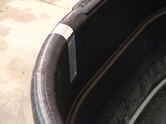
3 Video Clip 03 shows a close up of the fence construction. Video Clip 04 shows the insulated water tank. This is also shown above for Clip CCVolume 4J 3 3/18/04

4 Video Clip 05 and 06 show the tank and the cow contact points on the tank. The left rear contact point was not used. CCVolume 4J 4 3/18/04

5 CCVolume 4J 5 3/18/04

6 Video Clip 07 shows the electric fencer unit and how it was connected to the electric fence and the earth. CCVolume 4J 6 3/18/04

7 Video Clip 08 shows the digital voltmeter and this verifies the cow resistor to be 492 ohms. CCVolume 4J 7 3/18/04

8 CCVolume 4J 8 3/18/04
9 Video Clip 09 shows the tank full of water. The foam float is added to identify the water level. CCVolume 4J 9 3/18/04

10 Video Clip 10 shows the proximity of the electric fence to the tank for Test #1. CCVolume 4J 10 3/18/04
. When the overhead fluorescent lamps are turned on the background level rises to 0.1 millivolt (0.0001 volts). These background levels are insignificant for my test.")
11 Video Clip 11 shows the digital voltmeter connected to the tank, the fencer unit is off and with only overhead incandescent lights the background voltage level is millivolts ( volts). When the overhead fluorescent lamps are turned on the background level rises to 0.1 millivolt ( volts). These background levels are insignificant for my test. CCVolume 4J 11 3/18/04

12 Test 1: What is the effect on cattle drinking water from an insulated water trough if an electric fence is within inches of the water tank? This test was performed with tap water. No salt was added. Video Clip 12 shows the voltage across a 500-ohm cow resistor with the fencer operating. The digital voltmeter shows 1 millivolt in the still photo but it fluctuated up to approximately 10 millivolts. The digital voltmeter is not capable of making accurate measurements of short duration impulses. CCVolume 4J 12 3/18/04
. The duration of this peak is approximately 16 microseconds.")
13 As you view the oscilloscope output the actual voltage to the cow is as shown below: The peak voltage is in a negative direction and is 22 volts peak (22,000 millivolts). The duration of this peak is approximately 16 microseconds. CCVolume 4J 13 3/18/04
14 This impulse if plotted on the sensitivity chart produced at the University of Wisconsin shows that not even the 5% most sensitive cows in a herd would detect the voltage. This is a 1 cycle biphasic waveform and the upper curve should be referenced. 10,000 V Behavioral response for 5% of the most sensitive cows using sine waves from muzzle to hooves exposure Typ. Fencer 1,000 V 100 V 1 Cycle, Biphasic 1 Cycle, Monophasic Multiple Cycle 5 10 V Test #1 2 1 V (1,000 mv) USDA LOC PSCW LOC 0.1 V Higher Frequency Lower Frequency 0.01 V (10 mv) V (1 mv) 1000 on your AM radio dial 300 Hz (5th Harmonic) 1 millisecond 60 Hz ,000 10,000 Phase Duration (microseconds) = Time between voltage zero crossings Reprinted with permission C. Forster 7/5/00, 6/2003 Important note: Using a digital voltmeter for this test would imply that only 10 millivolts was applied the cow. In reality, the cow was exposed to peak voltages of 22,000 millivolts. CCVolume 4J 14 3/18/04

15 Test 2: What is the effect on cattle drinking water from an insulated water trough if an electric fence is contacting the water tank but there is no direct contact with the water? This test was performed with both tap water and tap water with salt added. Video Clip 13 shows the setup for this test and the results of the test. The electric fence wire is wrapped entirely around the tank to assure maximum contact with the outside of the water tank. The digital voltmeter is set to the Volts range and the cow resistor is 500 ohms. The digital meter fluctuates between and volts (4 to 5 millivolts). CCVolume 4J 15 3/18/04
. The duration of this peak is approximately 19 microseconds.")
16 As shown below the actual voltage to the cow would be: The peak voltage is in a positive direction (direction is not significant). The important factor is to select the greatest voltage peak value which is 90 volts peak (99,000 millivolts). The duration of this peak is approximately 19 microseconds. This impulse if plotted on the sensitivity chart produced at the University of Wisconsin shows that the 5% most sensitive cows in a herd would detect the voltage. This is a 1 cycle biphasic waveform and the upper curve should be referenced. CCVolume 4J 16 3/18/04
17 Behavioral response for 5% of the most sensitive cows using sine waves from muzzle to hooves exposure 10,000 V Typ. Fencer 1,000 V 100 V 1 Cycle, Biphasic 1 Cycle, Monophasic Multiple Cycle 5 10 V Test #2 2 1 V (1,000 mv) USDA LOC PSCW LOC 0.1 V Higher Frequency Lower Frequency 0.01 V (10 mv) V (1 mv) 1000 on your AM radio dial 300 Hz (5th Harmonic) 1 millisecond 60 Hz ,000 10,000 Phase Duration (microseconds) = Time between voltage zero crossings Reprinted with permission C. Forster 7/5/00, 6/2003 Please note that the video test clip shows a peak voltage of 80 volts. The above oscilloscope recording was made after adding 1 lb. of salt to the 150 gallons of water to simulate more conductive water conditions. Important note: Using a digital voltmeter for this test would imply that 4 to 5 millivolts was applied to the cow. In reality, the cow was exposed to peak voltages of 80-90,000 millivolts. CCVolume 4J 17 3/18/04

18 Test 3: What is the effect on cattle drinking water from an insulated water trough if the electric fence wire makes contact with the water in the water tank? This test was performed with tap water. No salt was added. Video Clip 14 and 15 show the connections for this test. CCVolume 4J 18 3/18/04

19 Having the electric fence connect directly to the water inside the tank is definitely NOT a good idea. I accidentally put one hand on the earth and contacted the water tank. The shock was definite, not painfull, but impossible to ignore. The voltage that was applied to the cow contact points was too large for my instruments to accept so I used both a 125-ohm and a 250-ohm cow resistor. The typical impedance of a cow s body to these short duration impulses is approximately 100 ohms versus the 500-ohm resistance used in the sensitivity chart. As you will see the recorded values at 125 and 250 ohms correlate well so we can double the voltage recorded across a 250-ohm cow to estimate the actual voltage a 500-ohm cow would experience. The sensitivity chart has been prepared using a 500-ohm cow. This means that the chart will predict behavioral changes before they actually occur in a dairy animal. CCVolume 4J 19 3/18/04
.")
20 Video Clip 16 shows the test performed with a 125-ohm cow resistor (4-500 ohm resistors in parallel). The digital voltmeter is set to the Volts range. The digital meter fluctuates up to 0.35 volts (350 millivolts). CCVolume 4J 20 3/18/04
21 As shown below the actual voltage to the cow would be: The peak voltage is in a positive direction and is almost 300 volts peak (300,000 millivolts). The duration of this peak is approximately 400 microseconds. I will not plot this voltage on the sensitivity chart because it was measured using a 125-ohm cow. Video Clip 17 shows the test performed with a 250-ohm cow resistor (2-500 ohm resistors in parallel). The digital voltmeter is set to the Volts range. The digital meter fluctuates up to 0.69 volts (690 millivolts). CCVolume 4J 21 3/18/04

22 CCVolume 4J 22 3/18/04
23 As shown below the actual voltage to the cow would be: The peak voltage is in a positive direction and is almost 580 volts peak (580,000 millivolts). The duration of this peak is approximately 400 microseconds. I will not plot this voltage on the sensitivity chart because it was measured using a 250-ohm cow. As you can see there is good correlation between the 125 and 250-ohm cow resistor. The 250-ohm resistor experiences approximately twice the voltage peak as the 125-ohm resistor. If I used a 500-ohm cow resistor I would expect to record peak voltages of approximately volts (1,100,000 to 1,200,000 millivolts). CCVolume 4J 23 3/18/04
24 This voltage is shown on the sensitivity chart and would definitely get a reaction from the cow. This is a 1 cycle monophasic waveform and the middle curve should be referenced. 10,000 V Behavioral response for 5% of the most sensitive cows using sine waves from muzzle to hooves exposure Typ. Fencer 1,000 V 100 V 1 Cycle, Biphasic 1 Cycle, Monophasic Multiple Cycle 5 10 V Test #3 2 1 V (1,000 mv) USDA LOC PSCW LOC 0.1 V Higher Frequency Lower Frequency 0.01 V (10 mv) V (1 mv) 1000 on your AM radio dial 300 Hz (5th Harmonic) 1 millisecond 60 Hz ,000 10,000 Phase Duration (microseconds) = Time between voltage zero crossings Reprinted with permission C. Forster 7/5/00, 6/2003 Important note: Using a digital voltmeter for this test would imply that 1400 to 1500 millivolts was applied to the cow. In reality, the cow was exposed to peak voltages of 1,100,000 to 1,400,000 millivolts. CCVolume 4J 24 3/18/04
25 Conclusions: From the above tests I can conclude the following: 1. Using a digital true rms voltmeter to measure impulses from a fencer will result in the user incorrectly assuming an animal responds to very low levels of electricity. The animal actually receives electrical shocks much greater than reported by the digital true rms voltmeter. In my video portion of this report I used a Fluke 189 digital voltmeter. I also used a Radio Shack Model and a Fluke 87. Each of these digital meters will measure the same low values as the Fluke 189. The use of any digital or analog multi-meter will produce incorrect data for this test. 2. Locating a plastic water tank near an electric fence is not a good practice, but if the tank does not contact the fence, the animals may not detect the electricity from the fencer. There are other points to consider. If the water tank causes the animals to crowd and one or more of the animals contacts the electric fence, they may avoid the area. If higher power electric fencers such as 50 mile and 100 mile fencers are used, you can expect more occurrences of voltage affecting the animals. 3. Allowing any metallic or electrically conductive connection between the electric fence wire and the water is clearly not a good idea. The animals will avoid the water tank. ps: Later in a deposition the author of the original water tank test claimed that the tests were performed using a digital meter in the peak hold mode. This would result in a higher reading on the digital meter, but still produce inaccurate data. If you are going to do a scientific experiment you must measure data correctly and to the highest degree of accuracy possible. If you have limitations in equipment, document the tests you performed so others will not misinterpret your data or conclusions. My conclusion remains: The original experiment does not show that animals are sensitive to a lower voltage than previously assumed by the scientific community. CCVolume 4J 25 3/18/04
26 Please see the liability disclaimer at the end of Volume 2001 Issue B. Chuck Forster, P.E. Fluke products can be viewed at Mr. Pulsar can be viewed at CCVolume 4J 26 3/18/04
The newer Fluke 199C recording scope meters are GREAT instruments if used properly.
 CowContacttm Volume 2004 Issue I March 2004 www.phasorlabs.com If you use FLUKE ScopeMeters and FlukeView logging software..see CowContact Volume 2G. If you use the Fluke 199C read this FLUKE ScopeMeters
Doing It Right. Phasor Labs. March voice fax
 Doing It Right Phasor Labs 5420 Glenway Circle Oregon, Wisconsin 53575 608-835-9605 voice 608-835-9039 fax cforster@phasorlabs.com March 2004 cforster@phasorlabs.com 1 Doing It Right March 2004 cforster@phasorlabs.com
Evaluating Electrical Events on the Dairy Farm
 Evaluating Electrical Events on the Dairy Farm What if we had a way to evaluate all the different measurements people make on a dairy farm and we could put this information into a form that the average
I. Introduction to Animal Sensitivity and Response
 Stray Voltage Field Guide Douglas J. Reinemann, Ph.D. Professor of Biological Systems Engineering University of Wisconsin Madison September 2007 Update I. Introduction to Animal Sensitivity and Response
Scopes for Stray Voltage. February
 Scopes for Stray Voltage February 2002 cforster@mailbag.com 1 Why use an oscilloscope? Those guys from the PSCW said just measure steady state February 2002 cforster@mailbag.com 2 Well the world is changing
I. Introduction to Animal Sensitivity and Response
 I. Introduction to Animal Sensitivity and Response The term stray voltage has been used to describe a special case of voltage developed on the grounded neutral system of a farm. If this voltage reaches
Measuring Stray Voltage. Steady state
 Measuring Stray Voltage What to measure: >Steady state >Motor starting transients >Impulses September 2000 cforster@forstereng.com 1 Steady state Where to measure: >All known cow contact points >Stanchions
Mr. Pulsartm. Specialized Function Generator
 Mr. Pulsartm Specialized Function Generator Getting Started: Turn the unit ON with the slide switch on the left side of the unit. The unit will stay on as long as you like, but leaving the unit powered
AE Agricultural Customer Services Play-by-Play Tekscope Manual
 1 2012 AE Agricultural Customer Services Play-by-Play Tekscope Manual TABLE OF CONTENTS I. Definitions II. Waveform Properties 1 III. Scientific Notation... 2 IV. Transient Levels of Concern a. ASAE Paper
2 : AC signals, the signal generator and the Oscilloscope
 2 : AC signals, the signal generator and the Oscilloscope Expected outcomes After conducting this practical, the student should be able to do the following Set up a signal generator to provide a specific
A Simple Notch Type Harmonic Distortion Analyzer
 by Kenneth A. Kuhn Nov. 28, 2009, rev. Nov. 29, 2009 Introduction This note describes a simple notch type harmonic distortion analyzer that can be constructed with basic parts. It is intended for use in
ECE 2006 University of Minnesota Duluth Lab 11. AC Circuits
 1. Objective AC Circuits In this lab, the student will study sinusoidal voltages and currents in order to understand frequency, period, effective value, instantaneous power and average power. Also, the
2.0 AC CIRCUITS 2.1 AC VOLTAGE AND CURRENT CALCULATIONS. ECE 4501 Power Systems Laboratory Manual Rev OBJECTIVE
 2.0 AC CIRCUITS 2.1 AC VOLTAGE AND CURRENT CALCULATIONS 2.1.1 OBJECTIVE To study sinusoidal voltages and currents in order to understand frequency, period, effective value, instantaneous power and average
Oscilloscope Applications MREC Rural Energy Conference 2012 Prepared by Paul Ortmann, P.E. /
 MREC Rural Energy Conference 2012 Prepared by Paul Ortmann, P.E. / portmann@idahopower.com Introduction An oscilloscope can help the user get more detailed electrical measurements than can be obtained
Contact Voltage Detection
 Contact Voltage Detection Midwest Rural Energy Conference 48th Annual Rural Energy Conference March 11-12 La Crosse, Wisconsin Chad Hadley, Senior Engineer Overview Contact Voltage Definition History Equipment
Fencing Options. Properly installed corner brace assemblies are the cornerstone of any fence. Fences with. A Horizontal brace (compression member)
") Fencing Options 125 The goal of fencing is to facilitate the management of the livestock herd. The type and design of a fencing system will vary with the type of animal and the level of management. Boundary
Fencing Options 125 The goal of fencing is to facilitate the management of the livestock herd. The type and design of a fencing system will vary with the type of animal and the level of management. Boundary
Instruction Manual. SSQ-2F Controller Board. For the. v1.41 For Rife Plasma Tube Systems. Manual v by Ralph Hartwell Spectrotek Services
 Instruction Manual For the SSQ-2F Controller Board v1.41 For Rife Plasma Tube Systems Manual v1.00 2012 by Ralph Hartwell Spectrotek Services This page intentionally blank. 2 Index and Table of Contents
Physics 120 Lab 1 (2018) - Instruments and DC Circuits
 - Instruments and DC Circuits") Physics 120 Lab 1 (2018) - Instruments and DC Circuits Welcome to the first laboratory exercise in Physics 120. Your state-of-the art equipment includes: Digital oscilloscope w/usb output for SCREENSHOTS.
Physics 120 Lab 1 (2018) - Instruments and DC Circuits Welcome to the first laboratory exercise in Physics 120. Your state-of-the art equipment includes: Digital oscilloscope w/usb output for SCREENSHOTS.
TYPES OF FENCING FOR GOATS. Steve Hart. E (Kika) de la Garza Institute for Goat Research Langston University Langston, Oklahoma
 de la Garza Institute for Goat Research Langston University Langston, Oklahoma") TYPES OF FENCING FOR GOATS Steve Hart E (Kika) de la Garza Institute for Goat Research Langston University Langston, Oklahoma 73050 Introduction Anyone that has goats knows that fencing them in is one
TYPES OF FENCING FOR GOATS Steve Hart E (Kika) de la Garza Institute for Goat Research Langston University Langston, Oklahoma 73050 Introduction Anyone that has goats knows that fencing them in is one
Mar07 Rev B
 Product Specification Ultraminiature Coax Connector (UMCC) and Cable Assemblies 108-2231 14Mar07 Rev B 1. SCOPE 1.1. Content This specification covers performance, tests and quality requirements for the
80i-110s AC/DC CURRENT PROBE
 Table of Contents 3 80i-110s AC/DC CURRENT PROBE Users Manual November 1996 1994, 1996 Fluke Corporation. All rights reserved. All product names are trademarks of their respective companies. Printed in
EQUIVALENT EQUIPMENT CIRCUITS
 INTRODUCTION EQUIVALENT EQUIPMENT CIRCUITS The student will analyze the internal properties of the equipment used in lab. The input resistance of the oscilloscope and digital multimeter when used as a
Testing DDX Digital Amplifiers
 Testing DDX Digital Amplifiers For Applications Assistance Contact: Ken Korzeniowski r. Design Engineer Apogee Technology, Inc. 19 Morgan Drive Norwood, MA 006, UA kkorz@apogeeddx.com TEL: 1-781-551-9450
PHYS Contemporary Physics Laboratory Laboratory Exercise: LAB 01 Resistivity, Root-mean-square Voltage, Potentiometer (updated 1/25/2017)
") PHYS351001 Contemporary Physics Laboratory Laboratory Exercise: LAB 01 Resistivity, Root-mean-square Voltage, Potentiometer (updated 1/25/2017) PART I: SOME FUNDAMENTAL CONCEPTS: 1. Limits on accuracy
PHYS351001 Contemporary Physics Laboratory Laboratory Exercise: LAB 01 Resistivity, Root-mean-square Voltage, Potentiometer (updated 1/25/2017) PART I: SOME FUNDAMENTAL CONCEPTS: 1. Limits on accuracy
EXAMPLE. Use this jack for the red test lead when measuring. current from 0 to 200mA. Figure P-1
 Digital Multimeters ON / OFF power switch Continuity / Diode Test Function Resistance Function Ranges from 200Ω to 200MΩ Transistor Test Function DC Current Function Ranges from 2mA to 20A. AC Current
Probe Considerations for Low Voltage Measurements such as Ripple
 Probe Considerations for Low Voltage Measurements such as Ripple Our thanks to Tektronix for allowing us to reprint the following article. Figure 1. 2X Probe (CH1) and 10X Probe (CH2) Lowest System Vertical
Sept 13 Pre-lab due Sept 12; Lab memo due Sept 19 at the START of lab time, 1:10pm
 Sept 13 Pre-lab due Sept 12; Lab memo due Sept 19 at the START of lab time, 1:10pm EGR 220: Engineering Circuit Theory Lab 1: Introduction to Laboratory Equipment Pre-lab Read through the entire lab handout
Audio Testing. application note. Arrakis Systems inc.
 Audio Testing application note Arrakis Systems inc. Purpose of this Ap Note This application note is designed as a practical aid for designing, installing, and debugging low noise, high performance audio
Q-Tech. Q-Tech Commercial Series QTA 1360P/1480P Power Amplifiers. User Manual
 Q-Tech Power Amplifiers WARNING THIS APPLIANCE MUST BE EARTHED General Installation DO NOT run unbalanced high impedance microphone cables near mains, data, telephone or 70/100V line cables. DO NOT run
Qualification Test Report Mini-Universal MATE-N-LOK* Connector
 Qualification Test Report Mini-Universal MATE-N-LOK* Connector 501-589 21 May 12 Rev B 1. INTRODUCTION 1.1. Purpose 1.2. Scope Testing was performed on the Tyco Electronics Mini-Universal MATE-N-LOK* Connectors
To Float or Not to Float? Analysis of a floating vs. grounded output Associated Power Technologies
 To Float or Not to Float? Analysis of a floating vs. grounded output Associated Power Technologies Introduction In electrical circuits, voltage is always measured between two points: a point of high potential
Signal Conditioning Amplifier
 FEATURES Accepts full, half, or quarter bridges; all bridgecompletion gages built in, including 120/1000- and 350-ohm dummies Fully adjustable and regulated bridge excitation on each channel; up to 12
The Variable Threshold Neutral Isolator (VTNI)
") The Variable Threshold Isolator (VTNI) Installation Instructions INTRODUCTION The is designed specifically for installation between the primary neutral of a power utility distribution system and the secondary
The Variable Threshold Isolator (VTNI) Installation Instructions INTRODUCTION The is designed specifically for installation between the primary neutral of a power utility distribution system and the secondary
201AP Charge Amplifier User Manual
 Trig-Tek 201AP Charge Amplifier User Manual Publication No. 980996 Rev. A Astronics Test Systems Inc. 4 Goodyear, Irvine, CA 92618 Tel: (800) 722-2528, (949) 859-8999; Fax: (949) 859-7139 atsinfo@astronics.com
NL800A - Stimulus Isolator
 NL800A - Stimulus Isolator Introduction The NL800A STIMULUS ISOLATOR is a battery powered, opto-coupled isolator. It has a constant current output, with very high output impedance, making it suitable for
TOA PROFESSIONAL POWER AMP
 Operating Instruction Manual TOA PROFESSIONAL POWER AMP Model P-150M, P-300M TOA ELECTRIC CO, LTD. KOBE, JAPAN Contents Precautions... 2 General Description... 2 Features... 3 Specifications... 4~5 Performance
EE 210: CIRCUITS AND DEVICES
 EE 210: CIRCUITS AND DEVICES LAB #3: VOLTAGE AND CURRENT MEASUREMENTS This lab features a tutorial on the instrumentation that you will be using throughout the semester. More specifically, you will see
11. AC-resistances of capacitor and inductors: Reactances.
 11. AC-resistances of capacitor and inductors: Reactances. Purpose: To study the behavior of the AC voltage signals across elements in a simple series connection of a resistor with an inductor and with
INSTRUCTION MANUAL. March 11, 2003, Revision 3
 INSTRUCTION MANUAL Model 701A Stimulator March 11, 2003, Revision 3 Copyright 2003 Aurora Scientific Inc. Aurora Scientific Inc. 360 Industrial Parkway S., Unit 4 Aurora, Ontario, Canada L4G 3V7 Tel: 1-905-727-5161
IEEE WORKING GROUP ON VOLTAGES AT PUBLICLY AND PRIVATELY ACCESSIBLE LOCATIONS. Web Cast May 17, 2007
 IEEE WORKING GROUP ON VOLTAGES AT PUBLICLY AND PRIVATELY ACCESSIBLE LOCATIONS Web Cast May 17, 2007 CHAIR CHUCK DENARDO (414) 221-3073 (chuck.denardo@we-energies.com) VICE CHAIR JIM BOUFORD (508) 421-7648
Electrical TP-18 February 2017 ELECTRICAL TECHNICAL PAPER 18 FREQUENTLY ASKED QUESTIONS ABOUT CATHODIC PROTECTION SYSTEM EQUIPMENT TESTING
 ELECTRICAL TECHNICAL PAPER 18 FREQUENTLY ASKED QUESTIONS ABOUT CATHODIC PROTECTION SYSTEM EQUIPMENT TESTING CATHODIC PROTECTION SYSTEM EQUIPMENT TESTING Question No. 1 What should I (the contractor) check
Experiment 3. Ohm s Law. Become familiar with the use of a digital voltmeter and a digital ammeter to measure DC voltage and current.
 Experiment 3 Ohm s Law 3.1 Objectives Become familiar with the use of a digital voltmeter and a digital ammeter to measure DC voltage and current. Construct a circuit using resistors, wires and a breadboard
Lab 9 Frequency Domain
 Lab 9 Frequency Domain 1 Components Required Resistors Capacitors Function Generator Multimeter Oscilloscope 2 Filter Design Filters are electric components that allow applying different operations to
Operational Amplifier
 Operational Amplifier Joshua Webster Partners: Billy Day & Josh Kendrick PHY 3802L 10/16/2013 Abstract: The purpose of this lab is to provide insight about operational amplifiers and to understand the
Experiment 2. Ohm s Law. Become familiar with the use of a digital voltmeter and a digital ammeter to measure DC voltage and current.
 Experiment 2 Ohm s Law 2.1 Objectives Become familiar with the use of a digital voltmeter and a digital ammeter to measure DC voltage and current. Construct a circuit using resistors, wires and a breadboard
Precalculations Individual Portion Introductory Lab: Basic Operation of Common Laboratory Instruments
 Name: Date of lab: Section number: M E 345. Lab 1 Precalculations Individual Portion Introductory Lab: Basic Operation of Common Laboratory Instruments Precalculations Score (for instructor or TA use only):
Array Solutions Four Square Array Manual and User s Guide
 Array Solutions Four Square Array Manual and User s Guide Array Solutions Four Square Array Pattern Steering System Congratulations! You have selected one of the finest phased array steering systems made.
Equivalent Equipment Circuits
 1. Introduction Equivalent Equipment Circuits The student will analyze the internal properties of the equipment used in lab. The input resistance of the oscilloscope and Digital MultiMeter (DMM) when used
Qualification Test Report SlimSeal SSL Connector
 Qualification Test Report SlimSeal SSL Connector 501-134042 6/26/15 Rev A 1. INTRODUCTION 1.1 Purpose Testing was performed on the TE Connectivity SlimSeal SSL Connector to determine its conformance to
ECE 231 Laboratory Exercise 3 Oscilloscope/Function-Generator Operation ECE 231 Laboratory Exercise 3 Oscilloscope/Function Generator Operation
 ECE 231 Laboratory Exercise 3 Oscilloscope/Function Generator Operation Laboratory Group (Names) OBJECTIVES Gain experience in using an oscilloscope to measure time varying signals. Gain experience in
VE7CNF - 630m Antenna Matching Measurements Using an Oscilloscope
 VE7CNF - 630m Antenna Matching Measurements Using an Oscilloscope Toby Haynes October, 2016 1 Contents VE7CNF - 630m Antenna Matching Measurements Using an Oscilloscope... 1 Introduction... 1 References...
Verifying the Wideband Input of an AC Measurement Standard
 Abstract erifying the of an AC Measurement Standard Speaker David Deaver Fluke Corporation PO Box 9090, Everett, WA, 98206 Phone: (425) 446-6434 FAX: (425) 446-5649 E-mail: david.deaver@fluke.com Authors:
Measurement and Analysis for Switchmode Power Design
 Measurement and Analysis for Switchmode Power Design Switched Mode Power Supply Measurements AC Input Power measurements Safe operating area Harmonics and compliance Efficiency Switching Transistor Losses
Back to the Basics Current Transformer (CT) Testing
 Testing") Back to the Basics Current Transformer (CT) Testing As test equipment becomes more sophisticated with better features and accuracy, we risk turning our field personnel into test set operators instead of
Back to the Basics Current Transformer (CT) Testing As test equipment becomes more sophisticated with better features and accuracy, we risk turning our field personnel into test set operators instead of
SNA Calibration For Use In Your Shack
 SNA Calibration For Use In Your Shack Introduction SNA calibration has been described as confusing and frustrating and its purpose is often misunderstood. The objective of this white paper is to remove
ANALOG TO DIGITAL CONVERTER ANALOG INPUT
 ANALOG INPUT Analog input involves sensing an electrical signal from some source external to the computer. This signal is generated as a result of some changing physical phenomenon such as air pressure,
Model Operating Manual
 Model 7500 DC to 1MHz Wideband Power Amplifier Operating Manual Copyright 2004. All rights reserved. Contents of this publication may not be reproduced in any form without the written permission of Krohn-Hite
Experiment 1: Instrument Familiarization (8/28/06)
") Electrical Measurement Issues Experiment 1: Instrument Familiarization (8/28/06) Electrical measurements are only as meaningful as the quality of the measurement techniques and the instrumentation applied
Electrical Measurement Issues Experiment 1: Instrument Familiarization (8/28/06) Electrical measurements are only as meaningful as the quality of the measurement techniques and the instrumentation applied
Q2. Figure 1 shows the oscilloscope trace an alternating current (a.c.) electricity supply produces.
 electricity supply produces.") SERIES AND PARALEL CIRCUITS Q1. A student set up the electrical circuit shown in the figure below. (a) The ammeter displays a reading of 0.10 A. Calculate the potential difference across the 45 Ω resistor.
SERIES AND PARALEL CIRCUITS Q1. A student set up the electrical circuit shown in the figure below. (a) The ammeter displays a reading of 0.10 A. Calculate the potential difference across the 45 Ω resistor.
Measuring Reflected Voltage Spikes in VFD Motor Applications
 Keywords: VFD, ASD, impedance mismatch, high frequency, reflected voltage, spikes, over voltage, ringing, cable length, inverter rated motor, turn to turn voltage, electric motor testing, oscilloscope,
Module 1, Lesson 2 Introduction to electricity. Student. 45 minutes
 Module 1, Lesson 2 Introduction to electricity 45 minutes Student Purpose of this lesson Explanations of fundamental quantities of electrical circuits, including voltage, current and resistance. Use a
Model Hz to 10MHz Precision Phasemeter. Operating Manual
 Model 6610 1Hz to 10MHz Precision Phasemeter Operating Manual Service and Warranty Krohn-Hite Instruments are designed and manufactured in accordance with sound engineering practices and should give long
EECS 318 Electronics Lab Laboratory #2 Electronic Test Equipment
 EECS 318 Electronics Lab Laboratory #2 Electronic Test Equipment Objectives: The purpose of this laboratory is to acquaint you with the electronic sources and measuring equipment you will be using throughout
Low-Cost Power Sources Meet Advanced ADC and VCO Characterization Requirements
 Low-Cost Power Sources Meet Advanced ADC and VCO Characterization Requirements Our thanks to Agilent Technologies for allowing us to reprint this article. Introduction Finding a cost-effective power source
Notes on DYNALYZER HVU Usage
 December 19, 1986 Notes on DYNALYZER HVU Usage It has been shown that the Dynalyzer HVU gives accurate reproduction of tube waveforms for almost all applications. Possible cautions, a) kv frequency response
RESISTANCE & OHM S LAW (PART I
 RESISTANCE & OHM S LAW (PART I and II) Objectives: To understand the relationship between potential and current in a resistor and to verify Ohm s Law. To understand the relationship between potential and
BENCHMARK MEDIA SYSTEMS, INC.
 BENCHMARK MEDIA SYSTEMS, INC. PPM-1 Meter Card Instruction Manual 1.0 The PPM... 1 1.1 The PPM-1... 1 2.1 Measurement Conventions... 1 2.2 System References... 2 3.0 Connections to the PPM-1 Card... 2
A 11/89. Instruction Manual and Experiment Guide for the PASCO scientific Model SF-8616 and 8617 COILS SET. Copyright November 1989 $15.
 Instruction Manual and Experiment Guide for the PASCO scientific Model SF-8616 and 8617 012-03800A 11/89 COILS SET Copyright November 1989 $15.00 How to Use This Manual The best way to learn to use the
Best Practices for Power and Transient Protection on Rosemount Radar Transmitters
 Technical Note Rosemount Radar Transmitters Best Practices for Power and Transient Protection on Rosemount Radar Transmitters BACKGROUND INTRODUCTION This document describes best practices for power and
RESISTANCE IN WIRES 4) 4R
 4R") RESISTANCE IN WIRES NAME: 1. A copper wire of length L and cross-sectional area A has resistance R. A second copper wire at the same temperature has a length of 2L and a cross-sectional area of 1 2A. What
RESISTANCE IN WIRES NAME: 1. A copper wire of length L and cross-sectional area A has resistance R. A second copper wire at the same temperature has a length of 2L and a cross-sectional area of 1 2A. What
Putting it All Together
 Putting it All Together 1. Vocabulary Review Write the term that correctly completes each statement. Use each term once. ampere electric current resistor battery series connection parallel connection electric
1587/1577. Insulation Multimeters. Technical Data. Two powerful tools in one.
 Test Equipment Depot - 800.517.8431-99 Washington Street Melrose, MA 02176 - TestEquipmentDepot.com 1587/1577 Insulation Multimeters Technical Data Two powerful tools in one. The Fluke 1587 and 1577 Insulation
ECG PATIENT SIMULATOR FIVE LEAD
 ECG PATIENT SIMULATOR FIVE LEAD PS-2005 USER MANUAL BC BIOMEDICAL PS-2005 TABLE OF CONTENTS WARNINGS, CAUTIONS, NOTICES... ii DESCRIPTION... 1 LAYOUT... 2 MANUAL REVISIONS... 6 LIMITED WARRANTY... 6 SPECIFICATIONS...
E-200D ALIGNMENT. See the end of the procedure for the location of the calibration points. EQUIPMENT REQUIRED
 E-200D ALIGNMENT NOTE: This is not an official B&K alignment procedure. This procedure was created by experimenting with an E-200D. However when this procedure is followed, the resulting calibration should
The University of Jordan Mechatronics Engineering Department Electronics Lab.( ) Experiment 1: Lab Equipment Familiarization
 Experiment 1: Lab Equipment Familiarization") The University of Jordan Mechatronics Engineering Department Electronics Lab.(0908322) Experiment 1: Lab Equipment Familiarization Objectives To be familiar with the main blocks of the oscilloscope and
The University of Jordan Mechatronics Engineering Department Electronics Lab.(0908322) Experiment 1: Lab Equipment Familiarization Objectives To be familiar with the main blocks of the oscilloscope and
ENGR4300 Test 1A Answers Fall 2002
 1. Resistive circuits (20 points) Given: V1=5 volts. R1= 2000Ω, R2= 1000Ω, R3= 500Ω, R4= 400Ω a) (8 points) Find the total resistance of the circuit. RT=R1+R2//(R3+R4) (R3+R4) =.5K +.4K =.9K R234 = R2//(R3+R4)
Resistance and Ohm s law
 Resistance and Ohm s law Objectives Characterize materials as conductors or insulators based on their electrical properties. State and apply Ohm s law to calculate current, voltage or resistance in an
Class #3: Experiment Signals, Instrumentation, and Basic Circuits
 Class #3: Experiment Signals, Instrumentation, and Basic Circuits Purpose: The objectives of this experiment are to gain some experience with the tools we use (i.e. the electronic test and measuring equipment
Lab 1: Basic Lab Equipment and Measurements
 Abstract: Lab 1: Basic Lab Equipment and Measurements This lab exercise introduces the basic measurement instruments that will be used throughout the course. These instruments include multimeters, oscilloscopes,
Lab 4 Ohm s Law and Resistors
 ` Lab 4 Ohm s Law and Resistors What You Need To Know: The Physics One of the things that students have a difficult time with when they first learn about circuits is the electronics lingo. The lingo and
2 Recommended Tools / Supplies
 Bias Scout TM Kit Assembly Manual Version 3.1 25 March 2015 1 Inventory of Parts 1 ea octal socket 1 ea octal base, brown (1 3/16" dia x 7/8" high) 1 ea 1.0 / 1W metal oxide, flame proof resistor 1 ea
LOVAG GENERAL INSTRUCTION G2 MEASUREMENT UNCERTAINTY. This instruction of a general nature and does not relate to specific standards.
 LTI-G2 LOVAG GENERAL INSTRUCTION G2 MEASUREMENT UNCERTAINTY This instruction of a general nature and does not relate to specific standards. It provides additional information ensuring a suitable degree
ECG PATIENT SIMULATOR SIX LEAD
 ECG PATIENT SIMULATOR SIX LEAD PS-2006 USER MANUAL BC BIOMEDICAL PS-2006 TABLE OF CONTENTS WARNINGS, CAUTIONS, NOTICES... ii DESCRIPTION... 1 LAYOUT... 2 MANUAL REVISIONS... 6 LIMITED WARRANTY... 6 SPECIFICATIONS...
FMR622S DUAL NARROW BAND SLIDING DE-EMPHASIS DEMODULATOR INSTRUCTION BOOK IB
 FMR622S DUAL NARROW BAND SLIDING DE-EMPHASIS DEMODULATOR INSTRUCTION BOOK IB 1222-22 TABLE OF CONTENTS SECTION 1.0 INTRODUCTION 2.0 INSTALLATION & OPERATING INSTRUCTIONS 3.0 SPECIFICATIONS 4.0 FUNCTIONAL
ASC-50. OPERATION MANUAL September 2001
 ASC-5 ASC-5 OPERATION MANUAL September 21 25 Locust St, Haverhill, Massachusetts 183 Tel: 8/252-774, 978/374-761 FAX: 978/521-1839 TABLE OF CONTENTS ASC-5 1. ASC-5 Overview.......................................................
EE431 Lab 1 Operational Amplifiers
 Feb. 10, 2015 Report all measured data and show all calculations Introduction The purpose of this laboratory exercise is for the student to gain experience with measuring and observing the effects of common
OSCILLOSCOPES, MULTIMETERS, & STRAIN GAGES
 Community College of Allegheny County Unit 1 Page 1 OSCILLOSCOPES, MULTIMETERS, & STRAIN GAGES The Overweight Sub That Cost Billions: After Spain invested $2.7 billion in a program for diesel-electric
RF Generators. Requirements:
 Requirements: RF Generators to deliver a requested forward power (adjustable) level into an RF system power level is adjusted manually, or power level is controlled by a digital or analog input signal
Experiment 2: Transients and Oscillations in RLC Circuits
 Experiment 2: Transients and Oscillations in RLC Circuits Will Chemelewski Partner: Brian Enders TA: Nielsen See laboratory book #1 pages 5-7, data taken September 1, 2009 September 7, 2009 Abstract Transient
The AD620 Instrumentation Amplifier and the Strain Gauge Building the Electronic Scale
 BE 209 Group BEW6 Jocelyn Poruthur, Justin Tannir Alice Wu, & Jeffrey Wu October 29, 1999 The AD620 Instrumentation Amplifier and the Strain Gauge Building the Electronic Scale INTRODUCTION: In this experiment,
Experiment 8: An AC Circuit
 Experiment 8: An AC Circuit PART ONE: AC Voltages. Set up this circuit. Use R = 500 Ω, L = 5.0 mh and C =.01 μf. A signal generator built into the interface provides the emf to run the circuit from Output
34134A AC/DC DMM Current Probe. User s Guide. Publication number April 2009
 User s Guide Publication number 34134-90001 April 2009 For Safety information, Warranties, Regulatory information, and publishing information, see the pages at the back of this book. Copyright Agilent
EE 241 Experiment #4: USE OF BASIC ELECTRONIC MEASURING INSTRUMENTS, Part III 1
 EE 241 Experiment #4: USE OF BASIC ELECTRONIC MEASURING INSTRUMENTS, Part III 1 PURPOSE: To become familiar with more of the instruments in the laboratory. To become aware of operating limitations of input
Exploring the Necessity of the Hot Hipot Test
 Exploring the Necessity of the Hot Hipot Test Introduction In an industry comprised of workers with varying electronics knowledge, a Hipot test can seem a daunting task for some. Indeed, many test operators
Experiment 1: Instrument Familiarization
 Electrical Measurement Issues Experiment 1: Instrument Familiarization Electrical measurements are only as meaningful as the quality of the measurement techniques and the instrumentation applied to the
TA MHz ±700 V Differential Probe User s Manual. This probe complies with IEC , IEC CAT III, Pollution Degree 2.
 TA041 25 MHz ±700 V Differential Probe User s Manual This probe complies with IEC-1010.1, IEC-1010.2-031 CAT III, Pollution Degree 2. 1. Safety terms and symbols Terms appearing in this manual: WARNING
PRODUCT SPECIFICATION
 SMT SHIELDED JACKS W.E. TYPE SYSTEM 1.0 SCOPE This specification covers the Molex shielded W.E. type product line which comprises a shield plug (male) and a jack (female) I/O type connector. This system
3. Apparatus/ Materials 1) Computer 2) Vernier board circuit
 Computer 2) Vernier board circuit") Experiment 3 RLC Circuits 1. Introduction You have studied the behavior of capacitors and inductors in simple direct-current (DC) circuits. In alternating current (AC) circuits, these elements act somewhat
Experiment 3 RLC Circuits 1. Introduction You have studied the behavior of capacitors and inductors in simple direct-current (DC) circuits. In alternating current (AC) circuits, these elements act somewhat
ELECTROSURGICAL UNIT ANALYZER
 ELECTROSURGICAL UNIT ANALYZER ESU-2000A USER MANUAL BC BIOMEDICAL ESU-2000A TABLE OF CONTENTS WARNINGS, CAUTIONS, NOTICES... ii DESCRIPTION... 1 OVERVIEW... 2 OPERATING INSTRUCTIONS... 3 MANUAL REVISIONS...
LAB I. INTRODUCTION TO LAB EQUIPMENT
 1. OBJECTIVE LAB I. INTRODUCTION TO LAB EQUIPMENT In this lab you will learn how to properly operate the oscilloscope Agilent MSO6032A, the Keithley Source Measure Unit (SMU) 2430, the function generator