All brand and product names are trademarks, registered trademarks or service marks of their respective holders.
|
|
|
- Quentin Sullivan
- 5 years ago
- Views:
Transcription
1
2 IMPORTANT NOTICES General The operator of this equipment must read and follow the descriptions in this manual. Wrong operation or maintenance can cancel the warranty or cause injury. Do not copy any part of this manual without written permission from FURUNO. If this manual is lost or worn, contact your dealer about replacement. The contents of this manual and equipment specifications can change without notice. The example screens (or illustrations) shown in this manual can be different from the screens you see on your display. The screens you see depend on your system configuration and equipment settings. Save this manual for future reference. Any modification of the equipment (including software) by persons not authorized by FURUNO will cancel the warranty. All brand and product names are trademarks, registered trademarks or service marks of their respective holders. How to discard this product Discard this product according to local regulations for the disposal of industrial waste. For disposal in the USA, see the homepage of the Electronics Industries Alliance ( for the correct method of disposal. How to discard a used battery Some FURUNO products have a battery(ies). To see if your product has a battery, see the chapter on Maintenance. Follow the instructions below if a battery is used. Tape the + and - terminals of battery before disposal to prevent fire, heat generation caused by short circuit. In the European Union The crossed-out trash can symbol indicates that all types of batteries must not be discarded in standard trash, or at a trash site. Take the used batteries to a battery collection site according to your national legislation and the Batteries Directive 2006/66/EU. In the USA The Mobius loop symbol (three chasing arrows) indicates that Ni-Cd and lead-acid rechargeable batteries must be recycled. Take the used batteries to a battery collection site according to local laws. Ni-Cd In the other countries There are no international standards for the battery recycle symbol. The number of symbols can increase when the other countries make their own recycling symbols in the future. Cd Pb i
3 SAFETY INSTRUCTIONS The operator must read the safety instructions before attempting to operate this equipment WARNING CAUTION Indicates a potentially hazardous situation which, if not avoided, could result in death or serious injury. Indicates a potentially hazardous situation which, if not avoided, can result in minor or moderate injury. Warning, Caution Prohibitive Action Mandatory Action WARNING ELECTRICAL SHOCK HAZARD Do not open the equipment. Only qualified personnel should work inside the equipment. The antenna emits electromagnetic radio frequency (RF) energy, which can be harmful. Distances at which RF radiation level of 100, 10 and 2 W/m 2 are present are given below. 100 W/m 2 : Nil 10 W/m 2 : 0.1 m 2 W/m 2 : 1.0 m Immediately turn off the power at the switchboard if water leaks into the equipment or something is dropped in the equipment. Continued use of the equipment can cause fire or electrical shock. Contact a FURUNO agent for service. Do not disassemble or modify the equipment. Fire, electrical shock or serious injury can result. Do not place liquid-filled containers on the top of the equipment. WARNING LABEL A warning label is attached to the AC-DC power supply. Do not remove the label. If the label is missing or damaged, contact a FURUNO agent or dealer about replacement. WARNING To avoid electrical shock, do not remove cover. No user-serviceable parts inside. WARNING Immediately turn off the power at the switchboard if the equipment is emitting smoke or fire. Continued use of the equipment can cause fire or electrical shock. Contact a FURUNO agent for service. Make sure no rain or water splash leaks into the equipment. Fire or electrical shock can result if water leaks in the equipment. Do not operate the equipment with wet hands. Electrical shock can result. Name: Warning Label (1) Type: Code No.: Fire or electrical shock can result if a liquid spills into the equipment. Use the proper fuse. Use of the wrong fuse can cause fire or permanent damage to the equipment. ii
4 TABLE OF CONTENTS FOREWORD...iv SYSTEM CONFIGURATION...vi PROGRAM NUMBER...vii SYSTEM OVERVIEW...viii 1. OPERATION Description of Controls Turning the Power On and Off Adjusting Panel Dimmer and Contrast Menu Overview Menu operating procedure Entering Voyage-Related Data Setting CPA/TCPA Selecting a Display Plotter display Target list (displaying target data) Dangerous (target) list Static data display Dynamic data display Alarm status display Messages Sending a message Receiving messages TX and RX message logs Regional Operating Channels Viewing channels, Tx power Displaying, editing regional operating area status Enabling/Disabling Alarm Buzzer, Key Beep Long Range LR MODE (Long Range Mode) MSG27 TX Pilot Plug (Option) Viewing Initial Settings INLAND AIS OPERATION Activating the Inland AIS Selecting AIS Mode Entering Voyage-Related Data Static Data Dynamic Data Details Ship Display (Mobile Class A) Inland AIS Specific Messaging Text message ETA and RTA messages No. of persons message EMMA warning message Water level message Message logs Viewing Initial Settings Selecting Menu Language Selecting Units of Measurement Setting for Time Difference MAINTENANCE, TROUBLESHOOTING Maintenance Replacement of Fuse, Resetting the Breaker Replacement of fuse Resetting the breaker Troubleshooting Diagnostics Monitor unit test Transponder test Power on/off history Tx on/off history Alarm Status Error and System Messages GPS Monitor Displaying Sensor Status Restoring Default Settings AIS-SART Test Indication in Target List APPENDIX... AP-1 Menu Tree - Class A AIS... AP-1 Menu Tree - Inland AIS... AP-3 Parts List... AP-5 Parts Location... AP-6 Digital Interface (IEC Edition 4, IEC )... AP-8 VHF Channel List... AP-20 ERI Codes... AP-22 Terminology, Units, Symbols... AP-23 SPECIFICATIONS... SP-1 INDEX...IN-1 Declaration of Conformity iii
5 FOREWORD A Word to the Owner of the FA-150 FURUNO Electric Company thanks you for purchasing the FA-150 UAIS Transponder. We are confident you will discover why the FURUNO name has become synonymous with quality and reliability. Since 1948, FURUNO Electric Company has enjoyed an enviable reputation for quality and reliability throughout the world. This dedication to excellence is furthered by our extensive global network of agents and dealers. Your equipment is designed and constructed to meet the rigorous demands of the marine environment. However, no machine can perform its intended function unless properly operated and maintained. Please carefully read and follow the operation and maintenance procedures in this manual. We would appreciate feedback from you, the end-user, about whether we are achieving our purposes. Thank you for considering and purchasing FURUNO. Features The FA-150 is a universal AIS (Automatic Identification System) for open sea and inland waterways, capable of exchanging navigation and ship data between own ship and other ships or coastal stations. It complies with IMO MSC.74(69) Annex 3, A.694, ITU-R M and DSC ITU-R M.825. It also complies with IEC (Type testing standard), IEC (EMC and environmental conditions). The FA-150 consists of VHF and GPS antennas, a transponder unit, a monitor unit, and several associated units. The transponder contains a VHF transmitter, two TDMA receivers on two parallel VHF channels, a DSC channel 70 receiver, interface, communication processor, and internal GPS receiver. The internal GPS is a 12-channel all-in-view receiver with a differential capability, and provides UTC reference for system synchronization to eliminate clash among multiple users. It also gives position, COG and SOG when the external GPS fails. iv
6 The main features are Safety of navigation by automatically exchanging navigational data between ships and between ship and coast Static data: - MMSI (Maritime Mobile Service Identity) - IMO number (where available) - Call sign & name - Length and beam - Type of ship - Location of position-fixing antenna on the ship Dynamic data: - Ship s position with accuracy indication and integrity status - Universal Time Coordinated (UTC) - Course over ground (COG) - Speed over ground (SOG) - Heading - Rate of turn (ROT) where available Voyage-related data - Ship s draught - Navigation status (manual input) - Hazardous cargo (type) - Destination and ETA (at master s discretion) Short safety-related messages, free messages LCD panel satisfies the IMO minimum requirements plus simple plotting modes Interfaces for radar, ECDIS, PC for future networking expansion GPS/VHF combined antenna for easy installation available CPA/TCPA alarm Built-in GPS receiver for UTC synchronization and backup position-fixing device The Inland AIS feature is based on CCNR (Vessel Tracking and Tracing Standard for Inland Navigation). Inland AIS receives and sends SOLAS AIS information, and interfaces automatic data input such as blue sign, draught (in centimeters), air draught (height from waterline), hazardous cargo blue cone indication, euro ship identifier and inland ship type. Further, the inland AIS sends ETA (Estimated Time of Arrival) to lock, bridge, terminal, etc. and displays response as RTA (Requested Time of Arrival) from the lock, bridge or terminal. Information receivable from land stations include EMMA warning, water level data, etc. v
7 SYSTEM CONFIGURATION Either GPS antenna GSC-001 GPA-017S VHF antenna GPS/VHF combined antenna GVA-100 Distributor unit DB-1 MONITOR UNIT FA-1502 (two units may be connected) UNIVERSAL AIS MENU ENT DISP DIM NAV STATUS FA-150 PWR TRANSPONDER UNIT FA-1501 External display, Pilot plug, NavNet2, Sensor VDC Alarm system PC, Beacon receiver LAN Blue Sign Power supply PR-240 : Standard : Option : Local supply 100/110/115/200/ 24 VDC 220/230 VAC 1φ, 50/60Hz VDC GSC-001 GVA-100 FA-1501 FA-1502 DB-1 PR-240 Exposed to the weather Exposed to the weather Protected from the weather Protected from the weather Protected from the weather Protected from the weather vi
8 PROGRAM NUMBER PCB Location Program No. Version No. Date of Modification CPU (24P0062) MAIN (24P0035) Monitor Unit Transponder Unit GPS Receiver **: Minor Modification (Prog) (Boot) 01.** 01.** 02.** 02.** September (Prog) 03.** May ** 40** Transponder Unit 02.** September ** May 2012 vii
9 SYSTEM OVERVIEW System overview The Automatic Identification System (AIS) was originally developed to aid the Vessel Traffic Services (VTS) by use of a VHF transponder working on Digital Selective Call (DSC) at VHF CH70, and is still in use along the UK coastal areas and others. Some time later the IMO developed a Universal AIS using the new sophisticated technology called Self-Organized Time Division Multiple Access (SOTDMA) based on a VHF Data Link (VDL). The system operates in three modes autonomous (continuous operation in all areas), assigned (data transmission interval remotely controlled by authority in traffic monitoring service) and polled (in response to interrogation from a ship or authority). It is synchronized with GPS time to avoid conflict among multiple users (IMO minimum 2000 reports per minute and IEC requires 4500 reports on two channels). The VHF channels 87B and 88B are commonly used and in addition there are local AIS frequencies. Shipborne AIS transponders exchange various data as specified by the IMO and ITU on either frequency automatically set up by the frequency management telecommand received by the DSC receiver on ship. AIS-fitted AtoN broadcasts its identification, type of operation, location, displacement, etc. at 3-min intervals or at a reporting rate designated by the Administration authorities. Transponder Aids to Navigation (AtoN) VTS Center transmits TDMA CH management message including code, type, position, etc. of buoys every 3 min, and the AtoN broadcasts these messages for ships. Transponder Static and Dynamic information incl. MMSI, Name, POSN, HDG, COG, SOG VTS center The VTS center transmits a command on frequency assignment, slots, report rate, VHF output power, channel spacing, etc. (Assigned mode) Transponder Own ship Interrogation and Response Ship 1 All ships broadcast Static and Dynamic information (autonomous and continuous mode). If OS wants to know information about ship 1, OS shall send an interrogation in polling mode; then ship 1 will transmit her response on the same VHF channel without operator intervention. AIS system viii
10 Not all ships carry AIS The Officer of the Watch (OOW) should always be aware that other ships, and in particular leisure craft, fishing boats and warships, and some coastal shore stations (including Vessel Traffic Service centers) might not be fitted with AIS. The OOW should also be aware that AIS fitted on other ships as a mandatory carriage requirement might be switched off by the master if its use might compromise the security of the vessel. Thus, users are therefore cautioned to always bear in mind that information provided by AIS may not be giving a complete or correct picture of shipping traffic in their vicinity. Use of AIS in collision avoidance As an anti-collision aid, the AIS has the following advantages over radar: Information provided in near real-time Capable of instant presentation of target course alterations Not subject to target swap Not subject to target loss in clutter Not subject to target loss due to abrupt maneuvers Able to "detect" ships within VHF/FM coverage, including in some circumstances, around bends and behind islands. When using the AIS for anti-collision purposes it is important to remember that the AIS is an additional source of navigation information. It does not replace other navigational systems. The AIS may not be giving a complete or correct picture of shipping traffic in its vicinity. The use of the AIS does not negate the responsibility of the OOW to comply with all collision regulation requirements, especially the maintaining of a proper look-out. The prudent navigator uses all aids available to navigate the ship. Erroneous information Erroneous information implies a risk to other ships as well as your own. Poorly configured or improperly calibrated sensors might lead to incorrect information being transmitted. It is the user s responsibility to ensure that all information entered into the system is correct and up to date. ix
11 This page intentionally left blank. x
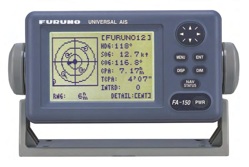
12 1. OPERATION 1.1 Description of Controls UNIVERSAL AIS MENU ENT DISP DIM NAV STATUS FA-150 PWR LCD Screen: Displays various data. 2 CursorPad: Shifts cursor; chooses menu items and options; selects alphanumeric data. 3 MENU key: Opens the menu. 4 ENT key: Terminates keyboard input; changes screen. 5 DISP key: Chooses a display screen; closes menu. 6 DIM key: Adjusts panel dimmer and LCD contrast. 7 NAV STATUS key: Displays NAV STATUS menu, which contains voyage-related data. 8 PWR key: Turns the power on and off. Notice: The nominal viewing distance is 50 cm. 1-1
13 1. OPERATION 1.2 Turning the Power On and Off Press the PWR key to turn the equipment on or off. When powered, the equipment sounds a beep then proceeds in the sequence shown below. The startup screen displays the program version number and the results of the ROM, RAM and backup data test, showing OK or NG (No Good) as the result. If NG appears for any of the check result, try resetting the power to restore normal operation. If that does not work, contact your dealer for advice. After the startup test is completed the plotter display appears, showing the messages NO OWN SHIP POSITION AVAILABLE. and NOW INITIALIZING. These messages mean that position data has not yet arrived and the transponder is initializing itself, respectively. When both messages disappear, the equipment is ready for use. If the message ENTER MMSI! appears, the vessel s MMSI has not been registered in the equipment. Enter MMSI. If there is no response from the transponder unit or AIS symbols do not appear, the message COMMUNICATION ERROR appears on the screen. Press any key to erase the message. Check if the transponder unit is powered. Also check the connection between the monitor unit and the transponder unit. 1-2
14 1. OPERATION The FA-150 should be powered while underway or at anchor. The master may switch off the AIS if he believes that the continual operation of the AIS might compromise the safety or security of his ship. The AIS should be restarted once the source of danger has gone. The equipment transmits own ship static data within two minutes of start-up and it is transmitted at six-minute intervals thereafter. Static data includes MMSI number, IMO number, call sign, ship name, ship length and width, ship type and GPS antenna position. In addition to static data, ship s dynamic data is also transmitted. This data includes position with quality indication, SOG, COG, rate of turn, heading, etc. Dynamic data is transmitted every 2 s to 3 min depending on ship s speed and course change. Voyage-related data, such as ship s draft, hazardous cargo, destination and estimated time of arrival, are transmitted at six-minute intervals. The FA-150 starts receiving data from AIS-equipped ships as soon as it is turned on, and those ships location are shown on the plotter display with the AIS symbol. (To learn more about the plotter display, see section 1.7.) With connection of a radar or ECDIS, the AIS target symbols may be overlaid on the radar or ECDIS. Note 1: If no navigation sensor is installed or a sensor such as a gyrocompass has failed, the AIS automatically transmits not available data to AIS-equipped ships. Note 2: The reporting intervals are as follows: Ship s dynamic conditions and nominal reporting interval Ship s navigation status Ship at anchor and not moving faster than 3 kn Ship at anchor and moving faster than 3 kn Ship speed 0-14 kn Ship speed 0-14 kn and changing course Ship speed kn Ship speed kn and changing course Ship speed faster than 23 kn Ship speed faster than 23 kn and changing course Nominal reporting interval 3 minutes 10 seconds 10 seconds 3 1/3 seconds 6 seconds 2 seconds 2 seconds 2 seconds 1-3
15 1. OPERATION 1.3 Adjusting Panel Dimmer and Contrast The panel dimmer and display contrast may be adjusted as follows: 1. Press the DIM key to show the dimmer and contrast setting screen. DIMMER (0~8) 4 CONTRAST (0~63) 44 EXIT: [ENT] 2. Use or to adjust the panel dimmer; or to adjust the contrast. (The default dimmer and contrast settings are 4 and 45, respectively. To restore default settings see section 3.9 Restoring Default Settings.) 3. Press the ENT key to close the setting screen. Note: If the equipment is turned off with the contrast setting of 35 or lower, the equipment will start up with the contrast setting 36 when the power is again turned on. 1-4
16 1.4 Menu Overview 1. OPERATION You can select the functionality of the equipment through the menu. If you get lost in operation, press the MENU key until you return to the main menu. The complete menu tree is provided in the Appendix Menu operating procedure 1. Press the MENU key to display the main menu. [MENU] MSG SENSOR STATUS INTERNAL GPS USER SETTINGS INITIAL SETTINGS CHANNEL SETTINGS DIAGNOSTICS 2. Press or on the CursorPad to select a menu then press the ENT key. 3. Press or to select a sub-menu then press the ENT key. There are two types of sub-menus: option selection and data input. (Some sub-menus combine both.) Below are examples of each type of sub-menu. 4. Press or to select a menu item then press the ENT key. 5. Depending on the sub-menu selected, select an option or enter alphanumeric data. 1-5
17 1. OPERATION Selecting an option The example below shows how to select an option from the USER SETTINGS menu. a) A window showing the options for the item selected is overlaid on the sub-menu. For example, the options for KEY BEEP are as shown below. [USER SETTINGS] KEY BEEP : ON ALARM BUZZER : ON AUTO SORT : ON OFF DISP SART TEST : ON LONG RANGE RECEIVED MSG CPA/TCPA ALARM Options window NOTE: For INLAND AIS mode, the USER SETTINGS menu has two pages. See section 2.9 to b) Press or to select option desired then press the ENT key. Entering alphanumeric data The example below shows how to enter numeric data on the DRAUGHT&PERSONS sub-menu, which is on the NAV STATUS menu. [DRAUGHT&PERSONS] DRAUGHT: 00.0 m NO. OF PERSONS: 0 Cursor a) Select DRAUGHT and press the ENT key. b) Press or to select appropriate numeric. Pressing displays alphanumeric characters cyclically in order of blank space, alphabet, numerals, and symbols. c) Press to shift the cursor to the adjacent place, then use or to select alphanumeric character. d) Repeat steps b) and c) to finish entering data. To erase a character, insert a space. e) After entering all data, press the ENT key to register input. 6. Press the DISP key to close the menu. 1-6
18 1. OPERATION 1.5 Entering Voyage-Related Data There are six items on the NAV STATUS menu that you will need to enter at the start of a voyage. Navigation status Cargo type Arrival time Destination No. of persons Draught 1. Press the NAV STATUS key to open the NAV STATUS menu. 2. If your navigation status is different from that shown, follow the procedure below. If it is the same as shown, go to step 3. a) Press the ENT key. b) Press or to select appropriate status then press the ENT key. Refer to the data below to select appropriate nav status. 00: UNDER WAY USING ENGINE 01: AT ANCHOR 02: NOT UNDER COMMAND 03: RESTRICTED MANEUVERABILITY 04: CONSTRAINED BY HER DRAUGHT 05: MOORED 06: AGROUND 07: ENGAGED IN FISHING 08: UNDER WAY SAILING 09: RESERVED FOR HIGH SPEED CRAFT (HSC)* 1 10: RESERVED FOR WING IN GROUND (WIG)* 2 11: RESERVED FOR FUTURE USE 12: RESERVED FOR FUTURE USE 13: RESERVED FOR FUTURE USE 14: AIS-SART (ACTIVE) 15: NOT DEFINED = DEFAULT (ALSO USED BY AIS-SART UNDER TEST) * 1 : RESERVED FOR FUTURE AMENDMENT OF NAVIGATIONAL STATUS FOR SHIPS CARRYING DG, HS, OR MP, OR IMO HAZARD OR POLLUTANT CATEGORY C, HIGH SPEED CRAFT (HSC) * 2 : RESERVED FOR FUTURE AMENDMENT OF NAVIGATIONAL STATUS FOR SHIPS CARRYING DANGEROUS GOODS (DG), HARMFUL SUBSTANCES (HS) OR MARINE POLLUTANTS (MP), OR IMO HAZARD OR POLLUTANT CATEGORY A, WING IN GRAND (WIG) 3. Press to show the DESTINATION sub-menu. 1-7
19 1. OPERATION 4. NEW is selected; press the ENT key. [DESTINATION] ENTER A NEW DESTINATION QUIT:[NAV STATUS] NAV STATUS menu, DESTINATION sub-menu, destination input 5. Press the ENT key. Enter destination then press the ENT key. You can use up to 20 alphanumeric characters (\, ^,!,,, $, and * count as three characters), and enter 20 destinations. (For how to enter alphanumeric characters, see Entering alphanumeric data on page 1-6.) PROCESSING DESTINATIONS If you have already registered some destinations, the DESTINATION sub-menu looks something like the one below. From this screen you can select, edit or delete destinations. [DESTINATION] COTE D'IVOIRE ************* (0/3) [NEW?] COTE D'IVOIRE SAN FRANCISCO SEATTLE Current destination Destination list 1) Select appropriate destination then press the ENT key to show the options window below. SELECT EDIT DELETE 2) Select SELECT, EDIT or DELETE as appropriate then press the ENT key. Do one of the following according to your objective. SELECT: Select a destination. EDIT: Press the ENT key twice then edit the destination. DELETE: The prompt below appears. Press to select YES; press the ENT key. DESTINATION DELETE. ARE YOU SURE? YES NO 1-8
20 1. OPERATION 6. Press to show the ARRIVAL TIME sub-menu. [ARRIVAL TIME] DATE [UTC]: 25/APR TIME[UTC]: 0:00 7. DATE[UTC] is selected; press the ENT key. 8. Enter the date of arrival then press the ENT key. 9. TIME[UTC] is selected; press the ENT key. 10. Enter the estimated time of arrival, in 24-hour notation, then press the ENT key. 11. Press to show the CARGO TYPE sub-menu. [CARGO TYPE] TYPE NO.: 00 **** TYPE DETAIL**** NOT AVAILABLE 12. TYPE NO. is selected; press the ENT key. 13. Select type of vessel/cargo, referring to the table on the next page, then press the ENT key. Note 1: Only the second digit for the type of vessel is entered here; the first digit is entered on the INITIAL SETTINGS menu, during installation. Note 2: When Tanker is selected and the Nav status is Moored, output power is automatically switched to 1 W when SOG is less than 3 knots. Further, in the above condition, when SOG becomes higher than 3 knots, the pop-up message CHANGE NAV STATUS? appears and a beep sounds. (The pop-up message TX POWER CHANGED also appears to notify you that the Tx power has changed). To erase the pop-up message, press any key or lower SOG below 3 knots. 1-9
21 1. OPERATION 10 FUTURE USE ALL SHIPS OF THIS TYPE 60 PASSENGER SHIPS ALL SHIPS OF THIS TYPE 11 FUTURE USE CARRYING DG, HS, OR MP( ) 61 PASSENGER SHIPS CARRYING DG, HS, OR MP(X) 12 FUTURE USE CARRYING DG, HS, OR MP(Y) 62 PASSENGER SHIPS CARRYING DG, HS, OR MP(Y) 13 FUTURE USE CARRYING DG, HS, OR MP(Z) 63 PASSENGER SHIPS CARRYING DG, HS, OR MP(Z) 14 FUTURE USE CARRYING DG, HS, OR MP(OS) 64 PASSENGER SHIPS CARRYING DG, HS, OR MP(OS) 15 FUTURE USE FUTURE USE 65 PASSENGER SHIPS FUTURE USE 16 FUTURE USE FUTURE USE 66 PASSENGER SHIPS FUTURE USE 17 FUTURE USE FUTURE USE 67 PASSENGER SHIPS FUTURE USE 18 FUTURE USE FUTURE USE 68 PASSENGER SHIPS FUTURE USE 19 FUTURE USE NONE 69 PASSENGER SHIPS NONE 20 WIG ALL SHIPS OF THIS TYPE 70 CARGO SHIPS ALL SHIPS OF THIS TYPE 21 WIG CARRYING DG, HS, OR MP(X) 71 CARGO SHIPS CARRYING DG, HS, OR MP(X) 22 WIG CARRYING DG, HS, OR MP(Y) 72 CARGO SHIPS CARRYING DG, HS, OR MP(Y) 23 WIG CARRYING DG, HS, OR MP(Z) 73 CARGO SHIPS CARRYING DG, HS, OR MP(Z) 24 WIG CARRYING DG, HS, OR MP(OS) 74 CARGO SHIPS CARRYING DG, HS, OR MP(OS) 25 WIG FUTURE USE 75 CARGO SHIPS FUTURE USE 26 WIG FUTURE USE 76 CARGO SHIPS FUTURE USE 27 WIG FUTURE USE 77 CARGO SHIPS FUTURE USE 28 WIG FUTURE USE 78 CARGO SHIPS FUTURE USE 29 WIG NONE 79 CARGO SHIPS NONE 30 FISHING 80 TANKER ALL SHIPS OF THIS TYPE 31 TOWING 81 TANKER CARRYING DG, HS, OR MP(X) 32 LENGTH OF THE TOW EXCEEDS 200M OR BREADTH EXCEEDS 25M 82 TANKER CARRYING DG, HS, OR MP(Y) 33 ENGAGED IN DREDGING OR UNDERWATER OPERATIONS 83 TANKER CARRYING DG, HS, OR MP(Z) 34 ENGAGED IN DIVING OPERATIONS 84 TANKER CARRYING DG, HS, OR MP(OS) 35 ENGAGED IN MILITARY OPERATIONS 85 TANKER FUTURE USE 36 SAILING 86 TANKER FUTURE USE 37 PLEASURE CRAFT 87 TANKER FUTURE USE 38 FUTURE USE 88 TANKER FUTURE USE 39 FUTURE USE 89 TANKER NONE 40 HSC ALL SHIPS OF THIS TYPE 90 OTHER TYPE OF SHIP ALL SHIPS OF THIS TYPE 41 HSC CARRYING DG, HS, OR MP(X) 91 OTHER TYPE OF SHIP CARRYING DG, HS, OR MP(X) 42 HSC CARRYING DG, HS, OR MP(Y) 92 OTHER TYPE OF SHIP CARRYING DG, HS, OR MP(Y) 43 HSC CARRYING DG, HS, OR MP(Z) 93 OTHER TYPE OF SHIP CARRYING DG, HS, OR MP(Z) 44 HSC CARRYING DG, HS, OR MP(OS) 94 OTHER TYPE OF SHIP CARRYING DG, HS, OR MP(OS) 45 HSC FUTURE USE 95 OTHER TYPE OF SHIP FUTURE USE 46 HSC FUTURE USE 96 OTHER TYPE OF SHIP FUTURE USE 47 HSC FUTURE USE 97 OTHER TYPE OF SHIP FUTURE USE 48 HSC FUTURE USE 98 OTHER TYPE OF SHIP FUTURE USE 49 HSC NONE 99 OTHER TYPE OF SHIP NONE 50 PILOT 51 SEARCH AND RESCUE VESSELS 52 TUGS 53 PORT TENDERS 54 VESSELS WITH ANTI-POLL UTION FACILITIES OR EQUIPMENT 55 LAW ENFORCEMENT VESSELS 56 SPARE-FOR ASSIGNMENTS TO LOCAL VESSELS 57 SPARE-FOR ASSIGNMENTS TO LOCAL VESSELS 58 MEDICAL TRANSPORTS 59 SHIPS & AIRCRAFT OF STATES NOT PARTIES TO AN ARMED CONFLICT WIG: Wing in ground HSC: High speed craft DG: Dangerous goods HS: Harmful substances MP: Marine pollutants 0-9: Undefined 14. Press to display the DRAUGHT&PERSONS sub-menu. 15. DRAUGHT is selected; press the ENT key. 16. Enter ship s draught (setting range: (m)) then press the ENT key. 17. NO. OF PERSONS is selected; press the ENT key. 18. Enter total number of persons onboard (setting range: ) then press the ENT key. Enter 8191 for total greater than Press the DISP key to close the menu. [DRAUGHT&PERSONS] DRAUGHT: 0.0 m NO. OF PERSONS:
22 1.6 Setting CPA/TCPA 1. OPERATION Set the CPA (Closest Point of Approach) and TCPA (Time to Closest Point of Approach) range for which you want to be alerted to AIS targets which can be on a collision course. When a ship s CPA and TCPA are lower than that set here, the buzzer sounds (if active) and the message COLLISION ALARM appears. 1. Press the MENU key to open the main menu. 2. Select USER SETTINGS then press the ENT key. 3. Select CPA/TCPA ALARM then press the ENT key. [CPA/TCPA ALARM] CPA : 6.00 NM TCPA : 60 min ALARM MODE : ON ALARM BUZZER: ON QUIT[MENU] 4. CPA is selected; press the ENT key. 5. Enter CPA (setting range: NM) then press the ENT key. 6. TCPA is selected; press the ENT key. 7. Enter TCPA (setting range: 0-60 min) then press the ENT key. 8. ALARM MODE is selected; press the ENT key. 9. Select ON to activate the CPA/TCPA alarm; OFF to deactivate it. Press the ENT key. 10. ALARM BUZZER is selected; press the ENT key. 11. Select ON to enable the CPA/TCPA audio alarm, or OFF to disable it. Press the ENT key. 12. Press the DISP key to close the menu. 1-11
23 1. OPERATION 1.7 Selecting a Display Use the DISP key to select a display. Each time the key is pressed, the display changes in the sequence shown below. PLOTTER DISPLAY PLOTTER DISPLAY (See section ) TARGET LIST (See section ) TARGET LIST Switch between these displays with,. DANGEROUS LIST DANGEROUS (TARGET) LIST (See section ) When a dangerous target exists, the dangerous target list has priority. OWN STATIC DATA 1 OWN STATIC DATA 2 OWN STATIC DATA 3 OWN STATIC DATA 4 OWN STATIC DATA 5 OWN SHIP'S STATIC DATA Switch among these displays with. (See section ) OWN DYNAMIC DATA OWN SHIP'S DYNAMIC DATA (See section ) ALARM STATUS ALARM STATUS DISPLAY (See section 3.5.) 1-12
24 1. OPERATION Plotter display The plotter display, which automatically appears after the power-on sequence, shows the name, heading, SOG, COG, CPA and TCPA of AIS-equipped ships, AIS-SARTs, etc. within the range selected. The number of dangerous targets is also indicated. Data for ship target A target marker (hollow triangle) indicates the presence of a vessel equipped with AIS in a certain location and course. To find detailed information about a vessel, see section If two or more targets occupy a similar position, the display priority order is selected target, AIS-SART and ship target. Data for AIS-SART 1-13
25 1. OPERATION Operations on the plotter display 1. Press the DISP key to show the plotter display. 2. Use or to select the range. The available ranges are (in nm) 0.125, 0.25, 0.5, 0.75, 1.5, 3, 6, 12, and To find a target s data, see section Note 1: A target is declared a lost target under the conditions shown in the table below. A target is erased from the screen 6 minutes and 40 seconds after it is declared a lost target. Ship s navigation status Target declared as lost target after; Class A Ship at anchor or moored and not moving faster than 3 kn 10 minutes Ship at anchor or moored and moving at more than 3 kn 50 seconds 0-14 kn speed 50 seconds 0-14 kn speed with course change 50 seconds kn speed 30 seconds kn speed with course change 30 seconds Speed higher than 23 kn 10 seconds Speed higher than 23 kn with course change 10 seconds Class B Speed over ground less than 2 kn 10 minutes Speed over ground 2 kn or higher 150 seconds Note 2: When a target s CPA and TCPA are lower than set in section 1.6, the audio alarm sounds (if active). Press any key to silence the audio alarm. Take suitable measures to avoid collision. Note 3: "DNGR" (DANGER) appears at the end of the HDG line when a target's CPA and TCPA are lower than the CPA and TCPA alarm settings. Further, when a target becomes a lost target, LOST appears at the end of the HDG line. 1-14
26 1. OPERATION Target list (displaying target data) 1. At the plotter display, press the DISP key to show the TARGET LIST, which lists all AIS targets and AIS-SARTs being detected by the FA-150. Note 1: The dangerous target list appears when there are dangerous targets. You can switch to the target list by pressing. Note 2: If there is no data for the target selected, the message NO SEL appears. Hit any key to escape. Note 3: Targets are automatically sorted in range order (closest to furthest) when no key is operated for 30 seconds. Target order is then updated every five seconds. Note 4: When AUTO SORT on the USER SETTINGS menu is OFF, the range and bearing to a target are updated. However, target order is not updated. To do this, press, and targets are sorted in range order. NOW SORTING is shown while sorting. Note 5: To select a target on the plotter display, press or to select the target then press the ENT key. Press to select from nearest to furthest; to select from furthest to nearest. The display then looks something like the one shown at the top of the next page. If you wish to see other target data, go to step 3 below. Note 6: The information source is specified from obtained MMSI and ship's name of an AIS target. 2. Use or to select the target whose data you wish to view then press the ENT key. The display then looks something like one of the displays shown on the next several pages, according to type of target. 3. Use or to scroll the display to see other data. 1-15
27 1. OPERATION Ship info display, mobile class A 1-16
28 1. OPERATION Ship info display, mobile class B 1-17
29 1. OPERATION Base station display SAR (Search and Rescue) info display 1-18
30 1. OPERATION AIS-SART info display DNGR appears when CPA/TCPA of target is less than CPA/TCPA setting. If no signal is received from target, LOST appears. 6:40 later the target's data is erased. [SART INFO] 1/3 MMSI : STATUS: SART ACTIVE RNG : NM BRG : 9.4 CPA : 8.83NM TCPA : 43' 06 MMSI no. Status (SART ACTIVE (NAV STATUS: 14), SART TEST (NAV STATUS: 15)) Range Bearing CPA TCPA [SART INFO] 2/3 LAT : 'N LON : 'E SOG : 17.8kn COG : HDG : 213 ROT : R 0.1 /min PA : H Latitude Longitude Speed over the ground Course over the ground Heading Rate of turn Position Accuracy (H, High, L, Low) [SART INFO] 3/3 NAV STATUS: 14 ***STATUS DETAIL*** AIS SART (ACTIVE) Navigation status 14: SART ACTIVE, 15: SART TEST Status detail 1-19
31 1. OPERATION AtoN (Aid to Navigation) info display 1-20
32 1. OPERATION The table below shows all the AtoN types and names that may appear on the AtoN INFO display. A to N type and name Type Name of AtoN 0 DEFAULT, TYPE OF A TO N NOT SPECIFIED 1 REFERENCE POINT 2 RACON 3 OFF SHORE STRUCTURE 4 SPARE 5 LIGHT, WITHOUT SECTORS 6 LIGHT, WITH SECTORS 7 LEADING LIGHT FRONT 8 LEADING LIGHT REAR 9 BEACON, CARDINAL N 10 BEACON, CARDINAL E 11 BEACON, CARDINAL S 12 BEACON, CARDINAL W 13 BEACON, PORT HAND 14 BEACON, STARBOARD HAND 15 BEACON, PREFERRED CHANNEL PORT HAND 16 BEACON, PREFERRED CHANNEL STARBOARD HAND 17 BEACON, ISOLATED DANGER 18 BEACON, SAFE WATER 19 BEACON, SPECIAL MARK 20 CARDINAL MARK N 21 CARDINAL MARK E 22 CARDINAL MARK S 23 CARDINAL MARK W 24 PORT HAND MARK 25 STARBOARD HAND MARK 26 PREFERRED CHANNEL PORT HAND 27 PREFERRED CHANNEL STARBOARD HAND 28 ISOLATED DANGER 29 SAFE WATER 30 SPECIAL MARK 31 LIGHT VESSEL / LANBY / RIGS 1-21
33 1. OPERATION Dangerous (target) list You can easily find dangerous ships whose CPA and TCPA are lower than the CPA and TCPA alarm settings. 1. At the plotter display, press the DISP key to show the Target List (see section 1.7.2). Note 1: If the target list appears, press to show the dangerous list. Note 2: Targets are automatically sorted by TCPA when no key is operated for 30 seconds. Target order is then updated every five seconds. 2. Press to show the Dangerous List. 3. To find detailed information about a dangerous target, use or to select the target then press the ENT key. 4. To change page: or to go forward; or to go back. Note 1: The message LOST appears at the top of the Dangerous List when no AIS signal is received from the target selected. Note 2: CPA and TCPA are automatically updated when AUTO SORT on the USER SETTINGS menu is OFF, however target order is not updated. To do this, press, and the targets are sorted in TCPA order. NOW SORTING is shown while sorting Static data display The OWN STATIC DATA display shows, on five pages, your ship s static data, which includes MMSI, call sign and name, IMO number, type of ship and location of position-fixing antenna. This data should be checked once per voyage or once per month whichever is shorter. Data may be changed only on the authority of the master. 1. At the plotter display, press the DISP key twice to show OWN STATIC DATA. See the next page. 2. To view other own static data: or to go forward, or to go back. See the illustration on the next page for own ship s static data examples. 1-22
34 1. OPERATION 1-23
35 1. OPERATION Dynamic data display The OWN DYNAMIC DATA display shows your ship s dynamic data, which includes time, date, ship s position, SOG, COG, heading, ROT, position accuracy, and RAIM use. The Officer of the Watch should periodically check position, SOG and sensor information for quality. At the plotter display, press the DISP key three times to show the OWN DYNAMIC DATA display Alarm status display The alarm status display shows the date and time alarms were violated. For further details, see section Messages You may send and receive messages via VHF channels, to a specified MMSI or all AIS-equipped ships in the area. Messages can be sent to warn of safety of navigation; for example, an iceberg sighted. Routine messages are also permitted. Short safety-related messages are only an additional means to broadcast safety information. They do not remove the requirements of the GMDSS. When a message is received, the equipment beeps and the indication MESSAGE appears. The contents of the message may be viewed on the RX log. 1-24
36 1. OPERATION Sending a message 1. Press the MENU key to open the main menu. 2. Use or to select MSG then press the ENT key. [MSG] CREATE MSG TX LOG RX LOG 3. CREATE MSG is selected; press the ENT key. (For Inland AIS, additionally select CREATE MSG then press the ENT key.) [CREATE MSG] SET MSG TYPE SET MSG SEND MSG 4. SET MSG TYPE is selected; press the ENT key. [SET MSG TYPE] ADRS TYPE: BROAD CAST MMSI : MSG TYPE : NORMAL CHANNEL: ALTERNATE RETRY TIMES: - MMS 5. ADRS TYPE is selected; press the ENT key. BROAD CAST ADRS CAST 6. Select ADRS CAST to send a message to a specific AIS-equipped ship, or BROAD CAST to send a message to all AIS-equipped ships within broadcasting range. Press the ENT key. 7. For BROAD CAST, go to step 8. For ADRS CAST, MMSI is selected; press the ENT key, enter MMSI number of the vessel that you want to receive your message, then press the ENT key. 8. MSG TYPE is selected; press the ENT key. SAFETY NORMAL 9. Select message type: NORMAL (message other than safety) or SAFETY (important navigational or meteorological warning). Press the ENT key. 10. CHANNEL is selected; press the ENT key. ALTERNATE BOTH A & B A B 11. Select which channel to transmit your message over then press the ENT key. 1-25
37 1. OPERATION 12. RETRY TIMES is selected; press the ENT key. If the ADRS TYPE is BROADCAST go to step For ADRS CAST, enter the number of times to re-transmit a message (0-3) then press the ENT key. 14. Press the MENU key to return to the CREATE MSG sub-menu. 15. Select SET MSG then press the ENT key. [SET MSG] *: Number of characters available with each message type for Class A, SOLAS is as follows: NORMAL message with BROAD-CAST : 156 characters NORMAL message with ADDRESS-CAST: 151 characters SAFETY message with BROAD-CAST : 161 characters SAFETY message with ADDRESS-CAST : 156 characters 01(151)* [DIM]HOLD:CLEAR Number of characters used/available 16. Use the CursorPad to enter your message. 17. Press the ENT key to return to the CREATE MSG sub-menu. 18. Select SEND MSG then press the ENT key. SEND MESSAGE. The prompt shown right appears. ARE YOU SURE? YES NO 19. Press to select YES then press the ENT key to send your message. Message status is shown as follows: AIS message status messages and their meanings Message NOW SENDING. SEND MESSAGE COMPLETE. PRESS ANY KEY SEND MESSAGE UNSUCCESSFUL. PRESS ANY KEY SEND MESSAGE UNSUCCESSFUL. MMSI: XXXXXXXXX PRESS ANY KEY NOW WAITING RESPONSE. PRESS ANY KEY Meaning Message is being sent. Transmission of message completed. (MMSI is additionally shown in case of addressed message.) Message could not be sent. Message sent successfully, however there is no reply from receiver of message. You tried to send a message while the transponder is awaiting receive confirmation (successful or unsuccessful) for the first-sent message. After confirmation is received, the next sequential message will be sent Receiving messages How to view a received message When a message is received, the window shown right appears on the display. To view the contents of the message follow the procedure below. MESSAGE! PRESS ANY KEY 1-26
38 1. OPERATION 1. Press any key to erase the message. 2. Press the MENU key to show the main menu. 3. Select MSG then press the ENT key. 4. Select RX LOG then press the ENT key. Date and time message received ("NEW" displayed for unread message) [RX LOG] 03/MAY 13:25 NEW [UTC] FROM: /MAR 03:43 [UTC] FROM: /MAR 18:00 [UTC] FROM: /3[ ] MSG[ENT] QUIT[MENU] MMSI of sender 5. To view the contents of a message, select the message then press the ENT key. The figure shown right is an example of a received message. [RX ADDRESSED MSG]* I HAVE CHANGED MY COURSE TO 350 DEGREE. 6. Press the DISP key to close the log. QUIT[MENU] *RX BROADCAST MSG for received broadcast message Automatically displaying incoming messages You can display incoming messages automatically as follows: 1. Press the MENU key to open the menu. 2. Select USER SETTINGS then press the ENT key. [USER SETTINGS] KEY BEEP : ON ALARM BUZZER : ON AUTO SORT : ON DISP SART TEST : ON LONG RANGE RECEIVED MSG CPA/TCPA ALARM NOTE: For INLAND AIS mode, the USER SETTINGS menu has two pages. See section 2.9 to Select RECEIVED MSG, then press the ENT key. [RECEIVED MSG] POPUP : ALL BUZZER : ON 4. Select POPUP, then press the ENT key 1-27
39 1. OPERATION 5. Select which category of receive message to display automatically then press the ENT key. ALL: Display any message upon receipt. ABM: Display only addressed binary messages, upon their receipt. OFF: Disable automatic displaying of incoming messages. ALL ABM OFF 6. To get an audio alert when the message type selected at step 5 is received, set "BUZZER" to ON. 7. Press the DISP key to close the menu TX and RX message logs The FA-150 stores the latest 20 each of transmitted and received messages in respective message logs. When a log becomes full, the oldest message in the log is automatically deleted to make room for the latest. When you receive a message, a popup shows MESSAGE! To display a message log, do the following: 1. Press the MENU key to open the menu. 2. Select MSG then press the ENT key. 3. Select TX LOG or RX LOG as appropriate then press the ENT key. Below is an example of the TX log. For the appearance of the RX log, see section Date and time message transmitted, message status OK: Message transmitted successfully FAIL: Message could not be transmitted : Waiting for results [TX LOG] 31/APR 13:25 OK [UTC] TO: /MAR 03:43 OK [UTC] TO: /MAR 18:00 OK [UTC] TO: /20[ ] MSG[ENT] QUIT[MENU] Time transmitted, addressee 4. To view the contents of a message, select it with or then press the ENT key. Below is an example of a transmitted message. For an example of a received message, see section [TX ADDRESSED MSG]* CHANGE YOUR COURSE TO 350 DEGREE. QUIT[MENU] *TX BROADCAST MSG for transmitted broadcast message 5. Press the DISP key to close the log. 1-28
40 1.9 Regional Operating Channels 1. OPERATION AIS operates primarily on two dedicated VHF channels, CH 2087 and CH2088. Where these channels are not available regionally, the AIS is capable of being automatically switched to designated alternate channels by means of a message from a shore facility. Where no shore based AIS or GMDSS sea area A1 station is in place, the AIS should be switched manually as in section A regional operating area is set with the procedure shown below. The most recent eight areas are memorized. Automatic setting of VHF DSC (channel 70) from shore-based AIS Automatic setting by AIS message from shore-based AIS Setting by shipboard system such as ECDIS Manual setting The default area is as follows: Tx power: 12.5 W Channel no. 2087, 2088 Frequency bandwidth: 25 khz Tx/Rx mode: Tx/Rx Viewing channels, Tx power Do the following to view current channels. 1. Press the MENU key to open the menu. 2. Select CHANNEL SETTINGS then press the ENT key. [CHANNEL SETTINGS] VIEW CHANNEL EDIT CHANNEL QUIT[MENU] 3. Select VIEW CHANNEL then press the ENT key. Power Channel [VIEW CHANNEL] POWER : 12.5W CHANNEL NO. CH-A: 2087 CH-B: Press the DISP key to close the display. QUIT[MENU] 1-29
41 1. OPERATION Displaying, editing regional operating area status You may display the status of regional operating areas currently memorized in the equipment. Nine of any combination of AIS message from shore-based AIS, DSC message, manual settings and commands from ECDIS or a PC may be registered and one will be HIGH SEA. About registering areas AIS and DSC messages registered within last two hours cannot be edited. An item labeled HIGH SEA cannot be registered. ( HIGH SEA are data used for international waters not controlled by shore-based AIS.) If two areas overlap one another the older data is deleted. Data older than five weeks is deleted. Area data is deleted when it is more than 500 miles from the area for which it was registered. 1. Press the MENU key to open the menu. 2. Select CHANNEL SETTINGS then press the ENT key. 3. Select EDIT CHANNEL then press the ENT key. SELECT NO.: File number, 0-9. In order of distance from own ship, from closest to furthest. TIME: Data and time equipment controlled by external source. [EDIT CHANNEL] SELECT NO. : 0 TIME [UTC] - -/ : - -: - - FROM MMSI: TYPE: MANUAL QUIT [MENU] EDIT[ENT] MMSI: TYPE: MMSI displayed for control by DSC or shore-based AIS. Dashes or EMPTY (no data) otherwise. How channel is controlled: AIS, AIS message; HIGH SEA (for reference setting), PI, ECDIS or PC; DSC, DSC; MANUAL, manual control Note: MMSI and TYPE must be set to other than HIGH SEA to edit. 4. Select desired file number from SELECT NO. 5. Press the ENT key to show details. [EDIT CHANNEL] 1/2 FROM MMSI: _ POWER : 12.5W CH NO. CH-A: 2087 CH-B: 2088 MODE CH-A: TX/RX CH-B: TX/RX ZONE: 1NM 6. POWER is selected; press the ENT key to show the channel power options. 1W 12.5W 1-30
42 1. OPERATION 7. Select power desired then press the ENT key. 8. CH NO. CH-A is selected; press the ENT key. 9. Select channel number for CH-A then press the ENT key. 10. CH NO. CH-B is selected; press the ENT key. 11. Select channel number for CH-B then press the ENT key. 12. MODE CH-A is selected; press the ENT key. TX/RX RX UNUSED 13. Select desired mode for CH-A then press the ENT key. Mode CH-A TX/RX TX/RX RX RX RX UNUSED CH-B TX/RX RX TX/RX RX UNUSED RX 14. MODE CH-B is selected; press the ENT key. 15. Select desired mode for CH-B then press the ENT key. 16. ZONE is selected; press the ENT key. 17. Key in the zone distance then press the ENT key. (The setting range is 1 to 8 (nm)). 18. Use or to show page 2 of the [EDIT CHANNEL] sub-menu. [EDIT CHANNEL] 2/2 CH AREA RIGHT TOP LAT: 'N LON: 'E LEFT BOTTOM LAT: 'N LON: 'E 19. LAT of RIGHT TOP is selected; press the ENT key. Enter latitude for the right-top position (northeast point) of the AIS operating area then press the ENT key. 20. LON of RIGHT TOP is selected; press the ENT key. Enter longitude for the right-top position (northeast point) of the AIS operating area then press the ENT key. 21. LAT of LEFT BOTTOM is selected; press the ENT key. Enter latitude for the left-bottom position (southwest point) of the AIS operating area then press the ENT key. 22. LON of LEFT BOTTOM is nm selected; press the ENT key. RIGHT-TOP Enter longitude for the left-bottom position (southeast point) of the AIS operating area then press the ENT key. Note: The available range is nm. If the area contains overlapping data the older data will be erased nm LEFT-BOTTOM ZONE 1-8 nm 1-31
43 1. OPERATION 23. Press the MENU key. The prompt shown right SAVE CHANNEL. appears. ARE YOU SURE? YES NO 24. Press to select YES then press the ENT key. Note: If a combination other than that shown in the table at step 13 is selected, the message ILLEGAL MODE WAS SELECTED PRESS ANY KEY. appears. 25. Press the DISP key to close the menu. Note: If you enter invalid data, the message OUT OF RANGE!: OO appears. Press any key to escape. Reenter data Enabling/Disabling Alarm Buzzer, Key Beep You may turn on or off the buzzers that sound for alarms or incoming messages. Further, you may turn off the beep, which sounds for valid key input. Note that the alarm buzzer is not related to a radar or ECDIS alarm. 1. Press the MENU key to open the menu. 2. Select USER SETTINGS then press the ENT key. [USER SETTINGS] KEY BEEP : ON ALARM BUZZER : ON AUTO SORT : ON DISP SART TEST : ON LONG RANGE RECEIVED MSG CPA/TCPA ALARM NOTE: For INLAND AIS mode, the USER SETTINGS menu has two pages. See section 2.9 to Select KEY BEEP or ALARM BUZZER as appropriate then press the ENT key. 4. Select ON or OFF as appropriate then press the ENT key. 5. Press the DISP key to close the menu Long Range The long range function sets how to reply to a request for own ship data from a distant station (for example, an Inmarsat C station) and whether to transmit your ship's position to a satellite via the AIS VHF communication link or not LR MODE (Long Range Mode) The long range mode sets how to reply to a request for own ship data from a distant station, for example, Inmarsat C station. You may reply automatically or manually. 1. Press the MENU key to open the menu. 2. Select USER SETTINGS then press the ENT key. 1-32
44 1. OPERATION 3. Select LONG RANGE then press the ENT key. 4. Select LR MODE then press the ENT key. 5. Select AUTO (auto reply) or MANUAL (manual reply) as appropriate then press the ENT key. 6. Press the DISP key to close the menu. Manual reply For manual reply, the requesting ship's MMSI, name and information requested (code, see next page) appear. Press the ENT key to send the data, or press any key other than ENT to send no data. The screen then changes according to your selection. Information requested (See table on next page.) [RECEIVED LR] MMSI: NAME: FURUNO C RESPONSE? YES: [ENT] NO: OTHER Press key [LR RESPONSE] MMSI: NAME: FURUNO C PRESS ANY KEY Automatic reply For automatic reply, the message below appears when a request for own ship data arrives from a distant station. Requested data is automatically transmitted. Press the ENT key to erase the message. [LR RESPONSE] MMSI: NAME: FURUNO C PRESS ANY KEY 1-33
45 1. OPERATION Codes used in long range messages Code A B C E F I O P U W Meaning Ship name, call sign, IMO number Date message created Position Course over ground Speed over ground Waypoint, ETA Draft Ship type, Load Ship length, width, type Number of crew MSG27 TX You can send own ship data to a satellite via the AIS VHF communication link. 1. Press the MENU key to open the menu. 2. Select USER SETTINGS then press the ENT key. 3. Select LONG RANGE then press the ENT key. 4. Select MSG27 TX then press the ENT key. [LONG RANGE] LR MODE MSG27 TX : AUTO : ON QUIT [MENU] 5. MSG27 TX is selected; press the ENT key. ON OFF 6. Select ON or OFF as appropriate then press the ENT key. ON sends your ship's position to a satellite via the AIS VHF communication link. 7. Press the DISP key to close the menu. 1-34


46 1.12 Pilot Plug (Option) 1. OPERATION A pilot plug, which is connected between the AIS and a PC, is required to feed AIS information to a PC. The plug is required for the ships passing through the Panama Canal and the Saint Lawrence Seaway. The specifications for the pilot plug are as shown below. Baudrate: bps Note: The following setting is required for the FA-150. If the pilot does not function, check these settings. Menu Setting [INITIAL SETTINGS]- [MODE]: [EXT DISPLAY] [VIEW I/O PORT]- [VIEW COM PORT]- [VIEW COM4] Type: AMP , (9-pin, male) Signal connection: TX-A Pin 1 TX-B Pin 4 RX-A Pin 5 RX-B Pin 6 SHIELD Pin 9 Connector for AIS Connector for PC Examples of connectors 1-35
47 1. OPERATION 1.13 Viewing Initial Settings The INITIAL SETTINGS menu, which is locked with a password, is where the installer enters ship s MMSI, internal and external antenna positions, ship type and I/O port settings. You can view the settings on this menu as follows. 1. Press the MENU to open the menu. 2. Select INITIAL SETTINGS then press the ENT key. 3. Press the ENT key twice. 4. Select item to view then press the ENT key. 1-36
48 2. INLAND AIS OPERATION This section provides the operating procedures for the Inland AIS feature, which allows use of the AIS transponder on inland waterways or the open sea. Only those procedures that are different from the Class A AIS transponder are presented. Ships with Inland AIS transponders on board autonomously determine their actual position using the Global Positioning System (GPS), which is part of the AIS transponder. Furthermore they broadcast their ID and position to other ships over a distance of 10 to 30 kilometers (depending on the geographical environment). Other ships in the area receive this information and are able to display their own position and that of other ships. Inland AIS helps the skipper in his direct nautical decisions, especially in critical situations, like the approach of a bend or a constriction. Further, authorities have the possibility to allow electronic submission of cargo lists e.g. for transports of dangerous cargo. The standard for Electronic Reporting (ERI) allows the digital, language independent submission of cargo or passenger reports from ships or agencies to authorities. In combination with electronic data exchange between the authorities of different countries this results in less reporting for the skippers. On the other hand all cargo information is available to authorities in case of an accident. 2.1 Activating the Inland AIS Enter your key number (received from dealer) to activate the Inland AIS. (If the key was entered during the installation, entry is not necessary.) 1. Press the MENU key to open the menu. 2. Select DIAGNOSTICS then press the ENT key. 3. Select ACTIVATE KEY then press the ENT key. [ACTIVATE KEY] DEVICE ID XX-XX-XX-XX-XX-XX KEY QUIT[MENU] 4. Press the ENT key, enter your activation key then press the ENT key. 5. Press the MENU key to quit. If you entered the activation key correctly, the indication "ACTIVATED!" appears then the system is automatically restarted. Start up with the SOLAS mode active. 2-1
49 2. INLAND AIS 2.2 Selecting AIS Mode The Inland AIS has two operating modes: Inland (inland waterways) and SOLAS (SOLAS compliant class A AIS transponder). Select desired mode as follows: 1. Press the NAV STATUS key to open the NAV STATUS menu. [NAV STATUS] NAV STATUS: 01 AIS MODE: SOLAS ***STATUS DETAIL*** AT ANCHOR 2. Push to select AIS MODE then press the ENT key. SOLASRX INLAND 3. Select SOLAS or INLAND as appropriate then press the ENT key. You are asked if you are sure to reboot the system. Select YES then press the ENT key to reboot. Notes on Inland AIS operation IMO NO. is transmitted with all zeroes. The draught used in Inland AIS is "Inland draught". The number of characters for a text message is as follows NORMAL MSG with BROAD-CAST: Solas, 156, Inland, 86 NORMAL MSG with ADDRESS-CAST: Solas, 151, Inland, 80 SAFETY MSG with BROAD-CAST: Solas, 161, Inland, 90 SAFETY MSG with ADDRESS-CAST: Solas, 156, Inland,
50 2. INLAND AIS 2.3 Entering Voyage-Related Data Before you embark on a voyage using Inland AIS, set the various voyage related data (see the list below) on the NAV STATUS menu. Destination Arrival time Draught Cargo type ERI code No. of persons Length and beam of ship Dynamic information rate Hazardous cargo Ship loading status 1. Press the NAV STATUS key. [NAV STATUS NAV STATUS: 0 AIS MODE: INLAND ***STATUS DETAIL*** UNDER WAY USING ENGINE 2. Press to show the DESTINATION sub-menu. [DESTINATION] ************* (0/0) [NEW?] 3. NEW is selected; press the ENT key. [DESTINATION] ENTER A NEW DESTINATION QUIT:[NAV STATUS] 2-3
51 2. INLAND AIS 4. Press the ENT key. Enter destination then press the ENT key. You can use up to 20 alphanumeric characters, and enter 20 destinations. (For how to enter alphanumeric characters, see Entering alphanumeric data on page 1-6.) Note 1: Each of the characters shown below counts as three characters.! $ *, \ Note 2: Destinations can be selected, edited and deleted from the DESTINATION sub-menu. See section Press to show the ARRIVAL TIME sub-menu. [ARRIVAL TIME] DATE [UTC]: - -/- - - TIME[UTC]: - -* DATE[UTC] is selected; press the ENT key. 7. Enter the date of arrival then press the ENT key. 8. TIME[UTC] is selected; press the ENT key. 9. Enter the estimated time of arrival then press the ENT key. Use 24-hour notation. 10. Press to show the DRAUGHT sub-menu. [DRAUGHT] SOLAS DRAUGHT: INLAND DRAUGHT: 0.0 m 0.00m 11 SOLAS DRAUGHT is selected; press the ENT key. 12. Enter SOLAS draught (tenths place resolution) then press the ENT key. 13. INLAND DRAUGHT is selected; press the ENT key. 14.Enter inland draught (hundredths place resolution) then press the ENT key. 15. Press to show the CARGO TYPE sub-menu. [CARGO TYPE] TYPE NO.: 00 **** TYPE DETAIL**** NOT AVAILABLE 16. TYPE NO. is selected; press the ENT key. 2-4
52 2. INLAND AIS 17. Select type of vessel/cargo, referring to the table on page 1-10, then press the ENT key. Note 1: Only the second digit for the type of vessel is entered here; the first digit is entered on the initial settings menu, during installation. Note 2: When Tanker is selected and the Nav status is Moored, output power is automatically switched to 1 W when the SOG is less than 3 knots. Further, in the above condition, when the SOG becomes higher than 3 knots, the pop-up message CHANGE NAV STATUS? appears and a beep sounds. (The pop-up message TX POWER CHANGED also appears to notify you that the Tx power has changed). To erase the pop-up message, press any key or lower the SOG below 3 knots. 18. Press to go to the ERI CODE sub-menu. [ERI CODE] ERI CODE: 8000 ****CODE DETAIL**** VESSEL, TYPE UNKNOWN 19. ERI CODE is selected; press the ENT key. 20. Enter four-digit ERI code (type of ship), referring to the ERI code table in the Appendix, then press the ENT key. 21. Press to go to the NO. OF PERSONS sub-menu. [NO. OF PERSONS] CREW: _ PASSENGER: SHIPBOARD PERSONNEL _ NO. OF PERSONS: CREW is selected; press the ENT key. 23. Enter number of crew (0-254) then press the ENT key. 24. PASSENGER is selected; press the ENT key. 25. Enter number of passengers (0-8191) then press the ENT key. Enter "8191" if the total number of passengers is more than SHIPBOARD PERSONNEL is selected; press the ENT key. 27. Enter number of shipboard personnel (persons other than passengers and crew, 0-254) then press the ENT key. Note: Crew, passenger and shipboard personnel are sent in RFM55 messages. 28.NO. OF PERSONS is selected; press the ENT key. 2-5
53 2. INLAND AIS 29. Enter the total number of persons (sum of crew, passengers and shipboard personnel) onboard then press the ENT key. Note: NO. OF PERSONS is sent in IFM16 messages. 30. Press to go to the LENGTH&BEAM sub-menu. [LENGTH&BEAM] LENGTH OF SHIP BEAM OF SHIP: 0.0 m 0.0 m 31. Enter the length and beam of your ship, pressing the ENT key after entering each item. (If LENGTH OF SHIP is more than three meters greater than the LENGTH OF CONVOY (A+B total for INT ANT POSN or EXT ANT POSN), the message "DIFFERENT FROM ANT POSN VALUE" appears. The same message also appears when the value for BEAM OF SHIP is more than three meters greater than the total for the BEAM OF CONVOY (C+D ANT POS.) 32. Press to go to the OTHER sub-menu. [OTHER] DYNAMIC INFORMATION RATE: AUTO HAZARDOUS CARGO: UNKNOWN UN/LOADED: UNKNOWN 33. DYNAMIC INFORMATION RATE is selected; press the ENT key. If the report rate from a base station is used, this setting is ignored. For that reason, this setting is not always the same as the actual report rate, which appears on page 2/2 of the DYNAMIC DATA screens. 34. Select AUTO, 10S, 5S or 2S as appropriate then press the ENT key. Note 1: This setting is fixed to AUTO in the SOLAS mode. Note 2: The new rate takes effect in 4-8 minutes. In the meantime the rate is AUTO, regardless of the indication. 2-6
54 2. INLAND AIS 35. HAZARDOUS CARGO is selected; press the ENT key. NUMBER OF CONES 0 NUMBER OF CONES 1 NUMBER OF CONES 2 NUMBER OF CONES 3 B-FLAG UNKNOWN 36. If your ship is carrying hazardous cargo, "cones" (max. 3) have to be shown on the mast, in daylight with cones and nighttime with blue lights. The greater the number of the cones the more hazardous the cargo. Select "NUMBER OF CONES 0" if your ship is not carrying hazardous cargo. Select B-FLAG if your ship carries explosives or hazardous cargo that exceeds the hazard level expressed with cones. Select UNKNOWN if you are unsure of cargo type. 37. Press the ENT key. 38. UN/LOADED is selected; press the ENT key. UNKNOWN LOADED UNLOADED 39. Select LOADED for vessel loaded with cargo, UNLOADED for vessel with no cargo, or UNKNOWN if you are unsure of the loading status. 40. Press the ENT key. 41. Press the DISP key to close the menu. 2-7
55 2. INLAND AIS 2.4 Static Data The STATIC DATA display shows various navigation data such as your MMSI no., ship name, etc. This data should be checked once per voyage or once per month whichever is shorter. Data may be changed only on the authority of the master. To show your static data, press the DISP key twice at the plotter display to show OWN STATIC DATA. Use or to go forward, or to go back. [STATIC DATA] 1/9 MMSI : NAME : FURUNO VOYAGER CALL SIGN: ZL6DEF1 IMO NO. : * ENI : AIS MODE : SOLAS MMSI no. Name of ship Call sign IMO no. ENI no. AIS mode * All zeroes (0) are transmitted when the Inland AIS mode is active. [STATIC DATA] 2/9 SOLAS DESTINATION: * * * * * * * * * * * * ** * * * * MAINZ Destination ETA: 15/JUL 11:22 UTC* Estimated date of arrival, estimated time of arrival [STATIC DATA] 3/9 INLAND DESTINATION COUNTRY CODE : DE LOCATION CODE : MAI FAIRWAY NO. : TERMINAL CODE : 00FRB FAIRWAY HECT : ETA: 15/JUL 11:22 UTC* Destination type Country code no. Location code no. Fairway section no. Terminal code no. Fairway hectometre no. Estimated date of arrival, estimated time of arrival * Time format shown as UTC (Coordinated Universal Time) or LT (Local Time). [STATIC DATA] 4/9 NAV STATUS: 01 UN/LOADED: UNLOADED ***STATUS DETAIL*** AT ANCHOR Navigation status no. Cargo status, unloaded, loaded, or unknown Navigation status description (Continued on next page) 2-8
56 2. INLAND AIS 2-9
57 2. INLAND AIS 2.5 Dynamic Data The DYNAMIC DATA display shows your ship s dynamic data, which includes date, time, ship s position, etc. To show these displays, press the DISP key three times at the plotter display. The Officer of the Watch should periodically check position, speed over ground and sensor information for quality. Date Time Latitude Longitude Speed over ground Course over ground, Heading Rate of turn [DYNAMIC DATA] 1/2 DATE: 10/APR/2008 TIME: 13:24:55 UTC LAT : 'N LON : 'E SOG: 8.1kn COG: HDG:118 ROT: R10.3 /min* * If no ROT device is connected and HDG sentence is input from a gyrocompass, etc., the following is displayed: Rate of turn less than 10 /min.: 0.0 Rate of turn 10 /min. rightward or higher: R>10 Rate of turn 10 /min. leftward or higher: L>10 [DYNAMIC DATA] 2/2 SENSOR: EXTERNAL GPS RAIM: USED POSITION ACCURACY HIGH DYNAMIC INFORMATION REPORT RATE: 3.3SEC BLUE SIGN: YES Navigator (EXTERNAL GPS, INTERNAL GPS, EXTERNAL DGPS, INTERNAL DGPS, NO FIX) Receiver Autonomous Integrity Monitoring (USED or UNUSED) Position accuracy (HIGH or LOW) Report rate for dynamic information Blue sign presence (YES or NO) ( "---" if BLUE SIGN on the INITIAL SETTINGS menu is "NOT AVAILABLE", or the SOLAS mode is in use.) Update rate of dynamic ship information Ship s dynamic conditions and nominal reporting interval Ship s dynamic conditions Ship at anchor and not moving faster than 3 kn Ship at anchor and moving faster than 3 kn Ship operating in SOLAS mode, moving 0-14 kn Ship operating in SOLAS mode, moving 0-14 kn speed and changing course Ship operating in SOLAS mode, moving kn Ship operating in SOLAS mode, moving kn and changing course Ship operating in SOLAS mode, moving faster than 23 kn Ship operating in SOLAS mode, moving faster than 23 kn and changing course Ship operating in inland waterway mode Nominal reporting interval 3 minutes 10 seconds 10 seconds 3 1/3 seconds 6 seconds 2 seconds 2 seconds 2 seconds Assigned between 2 seconds and 10 minutes 2-10
58 2. INLAND AIS 2.6 Details Ship Display (Mobile Class A) See section for how to show this display. [SHIP INFO] 1/9 MMSI [A] : NAME : FURUNO* CALL SIGN : ZL6DEF1* 1 IMO NO. : ENI : * 1, * 2 BLUE SIGN: YES [SHIP INFO] 2/9 LAT : 'N LON : 'E SOG : 17.8kn COG : HDG : 278 PA: H R/B : NM/351.5 ROT : 0.1 /min [SHIP INFO] 3/9 CPA : 0.12NM TCPA : 0'23" NAV STATUS: 10 ***STATUS DETAIL*** RESERVED FOR WING IN GROUND (WING) MMSI no. Name of ship Call sign IMO no. ENI no. Blue sign presence, absence "DNGR" (DANGER) appears (in reverse video) when a target's CPA and TCPA are lower than the CPA/TCPA setting. "LOST" appears (in reverse video) when signal from a target is lost. Six minutes and 40 seconds after loss of signal the target's data is erased. * 1 If any of these contain an "@" it is replaced with a space. Latitude Longitude Speed over ground Course over ground Heading, Position Accuracy (H, High, L, Low) Range and bearing from own ship Rate of turn * 2 The ENI (European Number of Identification) is an unique vessel identification number of barges, passenger ships and tugboats on European inland waters. CPA TCPA Navigation status Navigation status details [SHIP INFO] 4/9 SOLAS DRAUGHT: 10.0m INLAND DRAUGHT 10.00m ANT LENGTH A : 75m ANT LENGTH B : 20m ANT LENGTH C : 15m ANT LENGTH D : 15m SOLAS draught Inland draught Antenna position A Antenna position B Antenna position C Antenna position D [SHIP INFO] 5/9 LEN[SHIP]: 95.0m BEAM[SHIP]: 30.0m LEN[CONVOY]: 95m BEAM[CONVOY]: 30m HAZARDOUS CARGO NUMBER OF CONES 1 UN/LOADED: UNLOADED (Continued on next page) Length of ship Beam of ship Length of convoy Beam of convoy Hazardous cargo status (number of cones (0-3), blue sign, unknown) Vessel loading status (loaded, unloaded, unknown) 2-11
59 2. INLAND AIS (Continued from previous page) [SHIP INFO] 6/9 TYPE OF SHIP: 71 ***TYPE DETAIL*** FUTURE USE CARGO SHIP CARRYING DG, HS, OR MP(X) Type of ship Type of ship details [SHIP INFO] 7/9 ERI CODE: 8080 ERI code no. **CODE DETAIL*** MOTOR FREIGHTER WITH TANKER [SHIP INFO] 8/9 SENSOR QUALITY SPEED: HIGH COURSE: LOW HEADING: HIGH DESTINATION ROTTERDAM ETA: 15/JUL 17:21 UTC [SHIP INFO] 9/9 CREW: 10 PASSENGER: 100 SHIPBOARD PERSONNEL 20 NO. OF PERSONS: 130 Quality of speed data (HIGH, LOW) Quality of course data (HIGH, LOW) Quality of heading data (HIGH, LOW) Destination Estimated time of Arrival. The time format is shown as UTC (Coordinated Universal Time) or LT (Local Time). No. of crew No. of passengers No. of shipboard personnel No. of persons in total Note 1: BLUE SIGN information (contained in message type 1) is displayed when the FA-150 receives an RFM10* message type 6 (inland ship and voyage related data) or type 8 (safety-related message). When this happens, "BLUE SIGN" appears on page 1/9 of the DETAILS SHIP displays. If the target becomes lost but later is re-detected, the target is treated as a mobile station class A AIS target until BLUE SIGN information is again received. * RFM=Regional Function Message Note 2: A target detected as Inland AIS remains as such once information from the target is received, regardless of any subsequent AIS mode changes. 2-12
60 2. INLAND AIS 2.7 Inland AIS Specific Messaging Text message 1. Press the MENU key to open the menu. 2. Select MSG then press the ENT key. [MSG] TEXT ETA/RTA NO. OF PERSONS EMMA WARNING WATER LEVEL 3. TEXT is selected; press the ENT key. [TEXT] CREATE MSG TX LOG RX LOG 4. CREATE MSG is selected; press the ENT key. [CREATE MSG] SET MSG TYPEE SET MSG SEND MSG 5. SET MSG TYPE is selected; press the ENT key. [SET MSG TYPE] ADRS TYPE: BROAD CAST MMSI : MSG TYPE: SAFETY CHANNEL: ALTERNATE RETRY TIMES: - MMS 6. ADRS TYPE line is selected; press the ENT key. BROAD CAST ADRS CAST 7. Select ADRS CAST to send a message to a specific AIS-equipped ship, or BROAD CAST to send a message to all AIS-equipped ships within broadcasting range of your ship. Press the ENT key. For ADRS CAST, select MMSI then enter MMSI no. 2-13
61 2. INLAND AIS 8. Select MSG TYPE then press the ENT key. SAFETY NORMAL 9. Select message type: NORMAL (message other than safety) or SAFETY (important navigational or meteorological warning). Press the ENT key. 10. CHANNEL is selected; press the ENT key. ALTERNATE BOTH A & B A B 11 Select which channel to transmit your message over then press the ENT key. 12. RETRY TIMES is selected; press the ENT key. If the ADRS TYPE is BROAD CAST go to step 13. For ADRS CAST, enter the number of times to re-transmit a message (0-3) then press the ENT key. 13. Press the MENU key to return to the CREATE MSG sub-menu. 14. Select SET MSG then press the ENT key. [SET MSG] *: Number of characters available with each message type for Inland AIS is as follows: NORMAL message with BROAD-CAST : 86 characters NORMAL message with ADDRESS-CAST: 80 characters SAFETY message with BROAD-CAST : 90 characters SAFETY message with ADDRESS-CAST : 85 characters 1( 90)* [DIM]HOLD:CLEAR Number of characters used/available SET MSG screen 15.Use the CursorPad to enter your message. 16. Press the MENU key to return to the CREATE MSG sub-menu. 17. Select SEND MSG then press the ENT SEND MESSAGE. key. The prompt shown below appears. ARE YOU SURE? YES NO 18. Press to select YES then press the ENT key to send your message. Message status is shown as follows: AIS message status messages and their meanings Message Meaning NOW SENDING. Message is being sent. SEND MESSAGE COMPLETE. Transmission of message completed. (MMSI is additionally shown in PRESS ANY KEY. case of addressed message.) SEND MESSAGE UNSUCCESSFUL. Message could not be sent. PRESS ANY KEY SEND MESSAGE UNSUCCESSFUL. MMSI: XXXXXXXXX PRESS ANY KEY. NOW WAITING RESPONSE. PRESS ANY KEY Message sent successfully, however there is no reply from receiver of message. You tried to send a message while the transponder is awaiting receive confirmation (successful or unsuccessful) for the first-sent message. After confirmation is received, the next sequential message will be sent.
62 2. INLAND AIS ETA and RTA messages The purpose of an ETA message is to apply for a time slot at a lock, bridge or terminal. (Hereafter "lock" refers to lock, bridge or terminal.) The message contains your ship's ETA at the lock, air draught, the number of assisting tugboats required and the particulars of the lock (country code, location code, etc.). Upon receipt of your ETA message, the lock authority responds with an RTA (Requested Time of Arrival) message, usually within 15 minutes of receipt of the ETA message. The RTA message contains lock operational status, requested time of arrival and the particulars of the lock (country code, location code, etc.). Sending an ETA message 1. Press the MENU key to open the menu. 2. Select MSG then press the ENT key. [MSG] TEXT ETA/RTA NO. OF PERSONS EMMA WARNING WATER LEVEL 3. Select ETA/RTA then press the ENT key. [ETA/RTA] CREATE MSG ETA LOG RTA LOG 4. CREATE MSG is selected; press the ENT key. [CREATE MSG] SET MSG TYPEE SET DESTINATION SET ETA SEND MSG 5. SET MSG TYPE is selected; press the ENT key. [SET MSG TYPE] MMSI : CHANNEL: ALTERNATE RETRY TIMES: 3 MMS 2-15
63 2. INLAND AIS 6. MMSI is selected; press the ENT key. 7. Enter the MMSI of the lock/bridge/terminal you want to pass through then press the ENT key. 8. CHANNEL is selected; press the ENT key. ALTERNATE BOTH A & B A B 9. Select the channel over which to send the message then press the ENT key. 10. RETRY TIMES is selected; press the ENT key. 11. Enter the number of times to re-send the message (if the first transmission is unsuccessful) then press the ENT key. An ETA message can be resent a maximum of three times. 12. Press the MENU key to return to the CREATE MSG menu. 13. Select SET DESTINATION then press [SET DESTINATION] the ENT key. * * * * * * * * * * * * * (0/0) [NEW?] (If you have entered some destinations, they appear here.) 14. NEW is selected. If your destination is shown on screen, select it, press the ENT key then go to step 18. To enter a new destination, go to step With NEW selected, press the ENT key. [SET DESTINATION] ENTER A NEW DEST COUNTRY CODE: LOCATION CODE: FAIRWAY NO. : TERMINAL CODE: FAIRWAY HECT: QUIT: [MENU] UN country code, two 6 bit characters UN location code, three 6 bit characters Fairway section no., five 6 bit characters Terminal code, five 6 bit characters Fairway hectometre, five 6 bit characters 16. COUNTRY CODE is selected; press the ENT key. Enter the UN country code of your destination, referring to ISO 3166, then press the ENT key. 17. Enter location code, fairway no., terminal code, and fairway hectometre, referring to the ERI (Electronic Reporting International) Guide Part IV Annex 2 for examples. Note: To see the results of an entry, show the SET DESTINATION screen. [SET DESTINATION] * * * * * * * * * * * * * (0/1) [NEW?] NLRTM02552LEUVE00000 Fairway Hectometer Terminal Code Fairway No. Location Code Country Code 2-16
64 2. INLAND AIS 18. Press the MENU key twice to return to the CREATE MSG menu. 19. Select SET ETA then press the ENT key. The date and time format are shown as UTC (Coordinated Universal Time) or LT (Local Time). [SET ETA] ETA DATE[UTC] - - / TIME[UTC] - - : - - AIR DRAUGHT: 0.00 m NO. OF TUGBOATS: DATE[UTC] is selected; press the ENT key. 21. Enter the day (1-2 digits) and month (three-character abbreviation) of ETA then press the ENT key. 22. TIME[UTC] is selected; press the ENT key. 23. Enter your ETA, in 24-hour notation, then press the ENT key. 24. AIR DRAUGHT is selected; press the ENT key. 25. Enter your ship's air draught then press the ENT key. (Air draught is the vertical distance measured from the ship's waterline to the highest point on the ship.) 26. NO. OF TUGBOATS is selected; press the ENT key. 27. Enter the no. of assisting tugboats (0-6) your ship requires then press the ENT key. Enter "0" for none. 28. Press the MENU key to return to the CREATE MSG menu. 29. Select SEND MSG then press the ENT key. You are asked if you are sure to send the message. Select YES then press the ENT key to send the message. Receiving an RTA message A lock authority responds to an ETA message with an RTA message. An RTA message contains the date and time the lock authority requests that your ship arrive to the lock, lock status and the particulars of the lock (country code, location code, etc.) When an RTA message is received, a popup shows " MESSAGE! RTA". To view the message, do the following: 1. Press the MENU key to open the menu. 2. Select MSG then press the ENT key. 3. Select ETA/RTA then press the ENT key. 4. Select RTA LOG then press the ENT key to show the RTA log. A sample log is shown at the top of the next page. New or unread messages show "NEW" on the date and time line. When the time difference is 00:00, [UTC] is shown near the time indication. Otherwise, [LT] is shown. [RTA LOG] 31/APR 13:25 NEW [UTC] FROM: /MAR 03:43 [UTC] FROM: /MAR 18:00 [UTC] FROM: /20[ ] MSG[ENT] QUIT[MENU] 2-17
65 2. INLAND AIS 5. Select the message then press the ENT key. Lock Status - Operational - Limited Operation* - Out of Order - Not Available Date and time lock authority requests your ship to arrive to the lock * Obstructed by technical conditions, only one lock chamber available, etc. [RTA LOG] 1/2 STATUS LIMITED OPERATION RTA: 05/JUN 12:32 UTC** RTA message (page 1) [RTA LOG] 2/2 COUNTRY CODE: DE LOCATION CODE: TRI FAIRWAY NO.: TERMINAL CODE: FAIRWAY HECTOMETRE RTA message (page 2) **: Time format shown as UTC (Coordinated Universal Time) or LT (Local Time). 6. Press the MENU key to close the message. Lock particulars No. of persons message A number of persons message informs authorities or ships how many persons (passengers, crew, shipboard personnel) you have on board your ship. Send this message on request or in case of an event. 1. Press the MENU key to open the menu. 2. Select MSG then press the ENT key. 3. Select NO. OF PERSONS then press the ENT key. [NO. OF PERSONS] CREATE MSGE TX LOG 4. CREATE MSG is selected; press the ENT key. [CREATE MSG] SET MSG TYPEE VIEW MSG SEND MSG 5. SET MSG TYPE is selected; press the ENT key. [SET MSG TYPE] ADRS TYPE: BROAD CAST MMSI : TYPE: SOLAS (IFM16) CHANNEL: ALTERNATE RETRY TIMES: - MMS 2-18
66 2. INLAND AIS 6. ADRS TYPE is selected; press the ENT key. BROAD CAST ADRS CAST 7. Select ADRS CAST to send a message to a specific AIS-equipped ship or authority, or BROAD CAST to send a message to all AIS-equipped ships within broadcasting range. Press the ENT key. 8. For BROAD CAST, go to step 9. For ADRS CAST, select MMSI then press the ENT key. Enter the MMSI of the vessel which you want to receive your message then press the ENT key. 9. Select TYPE then press the ENT key. SOLAS(IFM16) INLAND(RFM55) 10. Select SOLAS(IFM16) or INLAND(RFM55) as applicable then press the ENT key. SOLAS(IFM16): Send no. of persons. INLAND(RFM55): Send no. of crew, passengers and shipboard personnel. 11. CHANNEL is selected; press the ENT key. ALTERNATE BOTH A & B A B 12. Select the channel to use to send the message then press the ENT key. 13. RETRY TIMES is selected; press the ENT key. 14. Enter the number of times to re-send the message (if the first transmission is unsuccessful) then press the ENT key. 15. Press the MENU key to return to the CREATE MSG menu. Note: To view your message before sending it, return to the CREATE MSG screen, select VIEW MSG then press the ENT key. [VIEW MSG] INLAND MSG(RFM55) CREW: 100 PASSENGER: 1000 SHIPBOARD PERSONNEL 200 SOLAS MSG(IFM16) NO. OF PERSONS: Select SEND MSG then press the ENT key. You are asked if you are sure to send the message. Select YES then press the ENT key to send the message. 2-19
67 2. INLAND AIS EMMA warning message EMMA (European Multiservice Meteorological Awareness) warnings are sent by base stations to skippers to inform them of special meteorological situations. EMMA does not provide continuous weather information, but only warnings of wind, rain, snow and ice, thunderstorm, fog, extreme temperatures (low and high), flood, fire in the forest. These messages are additional to the Notices to Skippers warnings. The information includes the following: Start time of validity End time of validity Fairway section start and end co-ordinates Type of weather warning Minimum value Maximum value Classification of warning Wind direction When you receive an EMMA warning, a popup displays "MESSAGE! EMMA WARNING". To see the contents of the message, do the following: 1. Press the MENU key to open the menu. 2. Select MSG then press the ENT key. 3. Select EMMA WARNING then press the ENT key. 4. Select a message then press the ENT key. The EMMA warning message has three pages and the 1 st page looks something like the left-hand screen on the next page. To view the other screens, press. [EMMA WARNING] 1/3 START TIME [UTC] 12/JUN 11:30 END TIME [UTC] 12/JUN 11:35 [EMMA WARNING] 2/3 START LAT : 'N LON : 'E END LAT : 'N LON : 'E [EMMA WARNING] 3/3 TYPE: SN SNOW AND ICE MIN VALUE: 1 cm/h MAX VALUE: 4 cm/h CLASS: MEDIUM WIND DIRECTION: NW Start and end times of validity of warning Fairway section start and end co-ordinates of warning Type, minimum and maximum values, class and wind direction (See below for description.) 2-20
68 2. INLAND AIS Item TYPE Description FI: Fire in the Forests FO: Fog FL: Flood HT: High Temperature LT: Low Temperature RA: Rain SN: Snow and Ice TH: Thunderstorm WI: Wind MIN, MAX VALUE CLASS WIND DIRECTION Units of measurement are fixed as follows: km/h (wind) C (temperature) cm/h (snow) l/m²h (rain) m (visibility distance in fog) The minimum and maximum value of respective item over one hour. For example, if the minimum and maximum values for snow and ice are 1 and 4 respectively, this means that 1-4 cm of snow or ice has fallen in one hour. The indication range is -254 to +254, or "----" in case where a value is not reported, for example, fire in the forests and flood. Weather classification: SLIGHT, MEDIUM, STRONG/HEAVY, " " (unknown) N, NE, E, SE, S, SW, W, NW 5. Press the MENU key to close the message. 2-21
69 2. INLAND AIS Water level message The water level message is sent by base stations to inform skippers about actual water levels in their area. It is additional short-term information to the water levels distributed via Notices to Skippers. The message contains the country code(location), gauge ID and water level. When you receive a water level message, a popup displays "MESSAGE! WATER LEVEL". To see the contents of the message, do the following: 1. Press the MENU key to open the menu. 2. Select MSG then press the ENT key. 3. Select WATER LEVEL then press the ENT key. 4. Select a message then press the ENT key. Country code National unique ID of gauge Positive or negative value [WATER LEVEL] 1/2 COUNTRY CODE: DE GAUGE ID: 1001 WATER LEVEL: 65.43m GAUGE ID: 1002 WATER LEVEL: 55.43m GAUGE ID: 1003 WATER LEVEL: m [WATER LEVEL] 2/2 GAUGE ID: 1004 WATER LEVEL: m 5. Press the MENU key to close the message Message logs TX logs The TX logs store transmitted text messages, ETA, and no. of persons messages, in respective logs. To see a TX message, do the following: 1. Press the MENU key to open the menu. 2. Select MSG then press the ENT key. 3. Select TEXT, ETA/RTA or NO. OF PERSONS as appropriate then press the ENT key. 4. Select TX LOG (for TEXT, NO. OF PERSONS) or ETA LOG as appropriate then press the ENT key. Date and time message transmitted, message status OK: Message transmitted successfully FAIL: Message could not be transmitted : Waiting for results [TX LOG] 31/APR 13:25 OK [UTC] TO: /MAR 03:43 OK [UTC] TO: /MAR 18:00 OK [UTC] TO: /20[ ] MSG[ENT] QUIT[MENU] Time transmitted, addressee NOTE: Time format is shown as UTC (Coordinated Universal Time) or LT (Local Time)
70 2. INLAND AIS 5. Select a message then press the ENT key. Below are sample TX log messages. [TX ADDRESSED MSG] CHANGING COURSE TO 357 DEGREES AT 12:35. [TX BROADCAST MSG] CHANGING COURSE TO 357 DEGREES AT 12:35. QUIT[MENU] TX addressed message [ETA LOG] 1/2 ETA: 05/JUN 12:32 UTC COUNTRY CODE: DE LOCATION CODE: TRI FAIRWAY NO.: TERMINAL CODE: FAIRWAY HECTOMETRE ETA message (page 1) [TX LOG] SOLAS(IFM16) NO. OF PERSONS: 100 QUIT[MENU] TX broadcast message [ETA LOG] 2/2 NUMBER OF TUGBOATS: 6 AIR DRAUGHT: 1.23m ETA message (page 2) [TX LOG] INLAND(RFM55) CREW: 100 PASSENGER: 255 SHIPBOARD PERSONNEL 41 SOLAS IFM16 no. of persons message INLAND RFM55 no. of persons message 6. Press the MENU key to close the message. RX logs The RX logs store received text messages, RTA, EMMA warning and water level messages, in respective logs. When you receive one of those messages, a popup shows "MESSAGE! XXX (XXX=message type)". To see the contents of the message, do the following: 1. Press the MENU key to open the menu. 2. Select MSG then press the ENT key. 3. Select RX LOG (Text), ETA LOG (ETA), RTA LOG (RTA), EMMA WARNING or WATER LEVEL as appropriate then press the ENT key. Below is the RX log for text messages. (The RX log for other message types is similar.) NEW: New or unread message Date and time message received [RX LOG] 31/APR 13:25 NEW [UTC] FROM: /MAR 03:43 [UTC] FROM: /MAR 18:00 [UTC] FROM: /20[ ] MSG[ENT] QUIT[MENU] MMSI of sender 2-23
71 2. INLAND AIS 4. Select the message to view then press the ENT key. Below are examples of text and RTA messages. For EMMA warning and water level messages, see section and 2.7.5, respectively. [RX ADDRESSED MSG] WILL CHANGE COURSE TO 352 DEGREES AT 13:10 APR 10. [RX BROADCAST MSG] STORM WARNING FOR SAN FRANCISCO AREA. QUIT[MENU] RX addressed message [RTA LOG] 2/2 STATUS LIMITED OPERATION RTA: 05/JUN 12:32 UTC QUIT[MENU] RX broadcast message [RTA LOG] 2/2 COUNTRY CODE: DE LOCATION CODE: TRI FAIRWAY NO.: TERMINAL CODE: FAIRWAY HECTOMETRE RTA message (page 1) RTA message (page 2) 5. Press the MENU key to close the message. 2.8 Viewing Initial Settings The INITIAL SETTINGS menu, which is locked with a password, is where the installer enters ship s MMSI, internal and external antenna positions, ship type, I/O port settings and blue sign status. You can view the settings on this menu as follows. 1. Press the MENU to open the menu. 2. Select INITIAL SETTINGS then press the ENT key. 3. Press the ENT key twice. 4. Select item to view then press the ENT key. 2-24
72 2. INLAND AIS 2.9 Selecting Menu Language You can select the language for menu window among English, French, Dutch or German. 1. Press the MENU key to open the menu. 2. Select USER SETTINGS then press the ENT key. 3. Select LANGUAGE (on page 2) then press the ENT key. [USER SETTINGS] 2/2 LANGUAGE : ENGLISH TIME DIFF : +00:00 ENGLISH RANGE CPA UNITS FRENCH : km SOG UNITS : kndutch LENGTH UNITS : mgerman Page 2 of [USER SETTEINGS] menu 4. Select the desired language then press the ENT key. 5. Press the DISP key to close the menu. 2-25
 as appropriate then press the ENT key. The options for each item are as follows. 4. Select the desired unit then press the ENT key. 5.")
73 2. INLAND AIS 2.10 Selecting Units of Measurement You can select the units of measurement for distance, length and speed. 1. Press the MENU key to open the menu. 2. Select USER SETTINGS then press the ENT key. 3. Select RANGE CPA UNITS, SOG UNITS or LENGTH UNITS (on page 2) as appropriate then press the ENT key. The options for each item are as follows. 4. Select the desired unit then press the ENT key. 5. Press the DISP key to close the menu Setting for Time Difference You can set the time differences from UTC (Universal Time Coordinated) to show the local time. When you select UTC for the time display, [UTC] is shown near the time indication. For local time, [LT] is shown. 1. Press the MENU key to open the menu. 2. Select USER SETTINGS then press the ENT key. 3. Select TIME DIFF (on page 2) then press the ENT key. +00:00 4. Select the desired time difference then press the ENT key. You can change the value with or, the digit with or. The setting range is -14:00 to +14:00. If you set the value outside the range, the error message appears shown below. Press any key to close the message. Error Message 5. Press the DISP key to close the menu. NOTE: When there is no time data from GPS, days in a leap year may be shifted. 2-26
74 3. MAINTENANCE, TROUBLESHOOTING WARNING ELECTRICAL SHOCK HAZARD Do not open the equipment. Only qualified personnel should work inside the equipment. NOTICE Do not apply paint, anti-corrosive sealant or contact spray to coating or plastic parts of the equipment. Those items contain organic solvents that can damage coating and plastic parts, especially plastic connectors. 3.1 Maintenance Regular maintenance is necessary to maintain performance. A monthly maintenance program should be established and should at least include the items listed in the table below. Maintenance items Item Connectors Cabling Ground terminal Ground wire Monitor unit, Transponder unit Check point Check that all connectors on the rear panel of the transponder unit and monitor unit are firmly connected. Check cabling for damage. Replace if damaged. Check the ground terminal on the monitor unit and transponder unit for rust. Clean if necessary. Check that the ground wire on the monitor unit and transponder unit is firmly fastened. Dirt and dust should be removed from units with a soft, dry cloth. For the LCD, wipe it carefully to prevent scratching, using tissue paper and an LCD cleaner. To remove dirt or salt deposits, use an LCD cleaner, wiping slowly with tissue paper so as to dissolve the dirt or salt. Change paper frequently so the salt or dirt will not scratch the LCD. Do not use solvents such as thinner, acetone or benzene for cleaning any unit; they can remove paint and marks and deform the equipment. 3-1
75 3. MAINTENANCE, TROUBLESHOOTING 3.2 Replacement of Fuse, Resetting the Breaker Replacement of fuse The power cable for the monitor unit contains a 3A fuse which protects the equipment from overvoltage, reverse polarity and equipment fault. If the power cannot be turned on, check if the fuse has blown. If the fuse has blown, find the cause before replacing the fuse. If the fuse blows again after replacement, contact your dealer for advice. Part Type Code No. Fuse FGBO-A 3A AC125V Use the proper fuse. WARNING Use of a wrong fuse can cause fire or result in damage to the equipment Resetting the breaker If the power cannot be turned on, the BREAKER button on the rear panel of the transponder unit may have activated. The BREAKER button pops out when overvoltage, reverse polarity or equipment fault is detected, to protect the system from damage. If the button pops out, find the reason before pushing it in to restore normal operation. Breaker BREAKER 10A VHF ANT GPS ANT PC 3-2
76 3.3 Troubleshooting 3. MAINTENANCE, TROUBLESHOOTING The troubleshooting table below provides common symptoms of trouble and the means to rectify them. If you cannot restore normal operation, do not attempt to check inside the equipment. Refer any repair work to a qualified technician. Symptom Power Cannot turn on the power. Troubleshooting Remedy Check that the power connector is firmly fastened. Check the power supply. Transmitting, receiving messages Cannot transmit or Check that the VHF antenna cable is firmly receive. fastened. Check the VHF antenna for damage. For TX message, try different TX channel. (operating sequence: MENU, MSG, CREATE MSG, SET MSG TYPE, CHANNEL) Can transmit but message is sent to wrong party. Position data No position data On the SET MSG TYPE sub-menu, check that ADRS TYPE is selected to ADRS-CAST and MMSI is correct, before sending a message. (operating sequence: MENU, MSG, CREATE MSG, SET MSG TYPE, ADRS TYPE and MMSI) Check the GPS antenna for damage. Check the GPS antenna cable and its connectors. 3.4 Diagnostics The FA-150 provides diagnostic tests to check the monitor unit and transponder unit for proper operation Monitor unit test The monitor unit test shows program no., and checks the ROM, RAM, LCD and controls. 1. Press the MENU key to open the main menu. 2. Select DIAGNOSTICS then press the ENT key. For service technician. Not accessible by user. [DIAGNOSTICS] MONITOR TEST TRANSPONDER TEST PWR ON/OFF HISTORY TX ON/OFF HISTORY MEMORY CLEAR ACTIVATE KEY FOR SERVICE 3-3
77 3. MAINTENANCE, TROUBLESHOOTING 3. MONITOR TEST is selected; press the ENT key. The test program automatically proceeds in the sequence shown below. XX.XX = Program version no. [MONITOR TEST] BOOT NO.: XX.XX PROG NO.: XX.XX ROM : CONT : SDRAM: DIM : PORT : KEY : PUSH KEY QUIT[MENU] 3 TIMES (a) [MONITOR TEST] BOOT NO.: XX.XX PROG NO.: XX.XX ROM : OK CONT :53 SDRAM: OK DIM : 4 PORT : OK KEY : QUIT[MENU] 3 TIMES (b) <LCD CHECK> ALL ON 2 SEC. ALL OFF 3 SEC. (e) (d) (c) a) The first screen in the test shows boot no. and program no. The message PUSH KEY prompts you to test the keys. Press each key (except the PWR key) and arrows on the CursorPad one by one. The name of the pressed key or arrow appears next to KEY if the control is functioning normally. b) The ROM, SDRAM and (I/O)PORT (special test connector required, otherwise NG appears) are checked. The results of the ROM/ SDRAM check are shown as OK or NG (No Good). If NG appears, try the test again. If NG still appears, contact your dealer for advice. The contrast and dimmer settings are automatically changed. Check that their setting indications are reasonable. c) The screen announces the start of the LCD check. d) The screen turns black. e) The screen turns white. 4. The test is repeated. To escape from the test and return to the DIAGNOSTICS menu, press the MENU key three times when PUSH KEY is displayed. 3-4
78 3. MAINTENANCE, TROUBLESHOOTING Transponder test The transponder test consists of two tests: memory test and internal GPS receiver test. Memory test The memory can be checked for proper operation and the program number displayed as follows: 1. Press the MENU key to open the main menu. 2. Select DIAGNOSTICS then press the ENT key. 3. Select TRANSPONDER TEST then press the ENT key. 4. Select MEMORY TEST then press the ENT key. The program no. is displayed and the ROM and RAM are checked. The results of the ROM and RAM check are shown as OK or NG (No Good). For any NG, contact your dealer for advice. The version of the Mother Board is also shown. [MEMORY TEST] PROGRAM NO xx.xx MAIN ROM : OK MAIN RAM : OK SUB RAM : OK MOT HW : x xx.xx: Program Version No. x: 0, Non-Inland AIS, other than 0: Inland AIS 5. Press the MENU key to return to the DIAGNOSTICS sub-menu. 3-5
79 3. MAINTENANCE, TROUBLESHOOTING Internal GPS test The internal GPS receiver can be checked for proper operation as follows: 1. Press the MENU key to open the main menu. 2. Select DIAGNOSTICS then press the ENT key. 3. Select TRANSPONDER TEST then press the ENT key. 4. Select GPS TEST then press the ENT key to start the test. The program no. and the test results appear as shown below. OK: Normal NG: (No Good). NG appears along with reason for NG: DATA BACKUP ERR: Data backup problem GPS COMMUNICATION ERROR: Comm. error with internal GPS receiver PARAMETER BACKUP ERR: Parameter backup problem ROM ERROR RAM ERROR ANTENNA ERROR [GPS TEST] PROGRAM NO xxxx TEST: OK xxxx: Program Version No. 5. Press the MENU key to return to the DIAGNOSTICS sub-menu.. 3-6
80 3. MAINTENANCE, TROUBLESHOOTING Power on/off history The PWR ON/OFF HISTORY log shows the date and time of the latest 30 power-ons and power-offs. If the interval between power-off and power-on is less than 15 minutes those times are not shown. 1. Press the MENU key to open the main menu. 2. Select DIAGNOSTICS then press the ENT key. 3. Select PWR ON/OFF HISTORY then press the ENT key. [PWR ON/OFF HISTORY] PWR-ON 17/MAY/ :35:54 PWR-OFF 17/MAY/ :56:57 PWR-ON 17/MAY/ :06:34 Power turned on 17 May 2009 at 05:35:54 QUIT[MENU] 4. Use or to change page in the forward direction; or to change page in the reverse direction. 5. Press the MENU key to return to the DIAGNOSTICS sub-menu Tx on/off history The TX ON/OFF HISTORY log shows the date and time of the latest 30 transmissions. 1. Press the MENU key to open the main menu. 2. Select DIAGNOSTICS then press the ENT key. 3. Select TX ON/OFF HISTORY then press the ENT key. [TX ON/OFF HISTORY] TX-ON 17/MAY/ :35:54 TX-OFF 17/MAY/ :34:57 TX-ON 17/MAY/ :33:57 Tx at 17 May 2009 at 05:35:54 PAGE (1/2) :[ ] QUIT[MENU] 4. Use or to change page in the forward direction; or to change page in the reverse direction. 5. Press the MENU key to return to the DIAGNOSTICS sub-menu. 3-7
81 3. MAINTENANCE, TROUBLESHOOTING 3.5 Alarm Status The alarm sounds for equipment error and is accompanied by a flashing popup indication. Press any key to silence the alarm and erase the popup. To see which alarm(s) has been violated, display the ALARM STATUS log as shown below. 1. At the plotter display, press the DISP key four times to show the ALARM STATUS display. Alarm name, date and time of alarm [ALARM STATUS] EPFS 7/MAY 4:32:16 L/L 7/MAY 4:02:01 SOG 7/MAY 2:34:54 COG 6/MAY 7:09:32 HDG 3/MAY 8:00:21 ROT 19/APR 9:05:22 2. Use or to scroll the log. Alarm statuses and their meanings Alarm Status Indication ANT CH1 CH2 CH70 COG EPFS FAIL HDG L/L MKD ROT SOG TX Meaning Antenna VSWR trouble. Continued operation possible. TDMA RX1 Board trouble. TX stopped on corresponding TX channel. TDMA RX2 Board trouble. TX stopped on corresponding TX channel. DSC RX Board trouble, transmission stopped on CH70. Invalid COG data No data from external navigator. Continued operation possible. General system failure Invalid/nonexistent HDG data No L/L data Minimum input device failure Invalid ROT data Invalid SOG data TX malfunction 3-8
82 3.6 Error and System Messages 3. MAINTENANCE, TROUBLESHOOTING The FA-150 displays the following error and system messages to alert you to errors and events. Error and system messages and their meanings Message Meaning CAN T DISPLAY INVALID DATA No position data. CAN T DISPLAY OVER LAT85 Own ship s latitude is higher than 85. COLLISION ALARM AIS target within set CPA/TCPA range. COMMUNICATION ERROR No communication with transponder. DIFFERENT FROM ANT POS VALUE ERROR REGIST GPS COMMUNICATION ERROR ILLEGAL COMBINATION OF PRIORITY ILLEGAL MODE WAS SELECTED. PRESS ANY KEY. INCORRECT NUMBER! PRESS ANY KEY INPUT THE UTC TIME! MESSAGE! MESSAGE! EMMA WARNING MESSAGE! RTA MESSAGE! TEXT MESSAGE! WATER LEVEL NO CREW NO ETA, DESTINATION NO MESSAGE NO NUMBER OF PERSONS NO OWN SHIP POSITION AVAILABLE NO PASSENGER NO SEL NO SHIPBOARD PERSONNEL OUT OF RANGE! For Inland AIS. Total sum of internal and external antenna distances are more than 3 meters greater than LENGTH (BEAM) OF SHIP. 1) You entered MSG22 or DSC data whose sea areas overlap one another, or wrong NAV STATUS 2) You entered NAV STATUS as 14 on page 1 of NAV STATUS menu. Communication error with internal GPS, shown at internal GPS self test. Duplication in priority setting. Invalid combination of channels is selected for editing. Incorrect ERI code entered. Input the UTC time when there is no time data from GPS. Class A AIS text message received. Inland AIS EMMA warning message received. Inland AIS RTA message received. Inland AIS text message received. Inland AIS water level message received Number of crew not entered in no. of persons message. You attempted to send a message that does not have ETA or destination. No TX message to send when you attempted to send a message. Number of persons not entered in no. of persons message. Invalid own ship position. Number of passengers not entered in no. of persons message. Attempted to see detailed data for a target which has no data. Number of shipboard personnel not entered in no. of persons message. Wrong IP, sub net mask or gateway address. 3-9
83 3. MAINTENANCE, TROUBLESHOOTING OUT OF RANGE! Invalid port number entered. OUT OF RANGE! Invalid NavNet port number entered. OUT OF RANGE! BEAM:0-100 Invalid beam of ship entered. OUT OF RANGE! CH-A(CH-B) Invalid channel entered. DOESN'T EXIST OUT OF RANGE! CPA: Invalid CPA range entered. OUT OF RANGE! CREW:0-254 Invalid crew no. entered. OUT OF RANGE! DAY Invalid day entered. OUT OF RANGE! DRAUGHT: OUT OF RANGE! DRAUGHT: Invalid inland draught entered. Invalid SOLAS draught entered. OUT OF RANGE! HOUR:0-23* Invalid hour entered. OUT OF RANGE!: INVALID Invalid CH-NO. A or CH-NO. B entered. CHANNEL OUT OF RANGE! LENGTH:0-800 Invalid ship's length entered. OUT OF RANGE! MINUTE:0-59* Invalid minute entered. OUT OF RANGE! NAV STATUS:0-15 Invalid nav status entered. OUT OF RANGE! Invalid no. of passengers entered. PASSENGER: OUT OF RANGE! Invalid no. of personnel entered. PERSONNEL:0-254 OUT OF RANGE! RETRY Invalid no. of retry times entered. TIMES:0-3. PRESS ANY KEY. OUT OF RANGE! TCPA:0-60 Invalid TCPA entered. OUT OF RANGE! TUGBOAT:0-6 Invalid tugboat quantity entered. OUT OF RANGE! TYPE NO.:10-99 Invalid cargo type entered. OUT OF RANGE! ZONE:1-8 Invalid zone entered. SEND MESSAGE UNSUCCESSFUL Message could not be sent. TRANSPONDER WAS REBOOTED Transponder was rebooted. * Error message displayed for both even if only one is out of range. Note: Detection of RX malfunction 1) Detection of TDMA RX malfunction Frequency error PLL chip on receiver board generates lock or unlock signal for synthesizer. MPU watches and sets status flag which reflects data of ALR sentence. ID 003 for RX1, ID 004 for RX2 2) Detection of DSC RX malfunction General error DSC Error (ID: 005) will happen in case of DSC MPU could not receive format specifier of the data from DSC amplifier unless RSSI exists more than 90 seconds. 3-10
84 3.7 GPS Monitor 3. MAINTENANCE, TROUBLESHOOTING The GPS monitor display shows information about the built-in GPS receiver, including position, speed over ground, course over ground, date, time, mode position accuracy, position-fixing status and RAIM status. 1. Press the MENU key to open the menu. 2. Select INTERNAL GPS then press the ENT key. Latitude position Longitude position Speed over ground, Course over ground Date Time Mode DGPS GPS NO FIX Position Accuracy H: High (<10 m, differential mode) L: Low (>10, autonomous mode) [INTERNAL GPS] LAT : 'N LON : 'E S/C : 10.9 kn/ 98.9 UTC : 16/MAY/ :29:02 DGPS STS: D3D PA: H RAIM: USED RAIM Status* (Receiver Autonomous Integrity Monitoring) USED or UNUSED STS (Position fix Status) 2D: 2D GPS position fix 3D: 3D GPS position fix D2D: 2D DGPS position fix D3D: 3D DGPS position fix DOP: HDOP > 4 in 2D fix, or HDOP > 6 in 3D fix NO FIX: No position fix *RAIM: Technique whereby the GPS receiver verifies the integrity of the signals received from the GPS constellation. 3. Press the DISP key to close the display. 3-11
85 3. MAINTENANCE, TROUBLESHOOTING 3.8 Displaying Sensor Status The SENSOR STATUS screen shows sensor status. 1. Press the MENU key. 2. Select SENSOR STATUS then press the ENT key. [SENSOR STATUS] Sensor status message UTC CLOCK LOST QUIT[MENU] 3. Press the DISP key to close the display. Sensor status messages and their meanings Sensor Status Message Meaning CH MANAGEMENT Channel changed (displayed about 30 s) EXT DGNSS Using external DGNSS EXT GNSS Using external GNSS EXT SOG/COG Using external SOG/COG HDG VALID Heading data normal INT DGNSS BEACON Using internal DGNSS beacon INT DGNSS MSG 17 MSG 17 corrects internal GNSS with differential correction INT GNSS Using internal GNSS INT SOG/COG Using internal SOG/COG OTHER ROT Value calculated from HDT, or ROT device used and talker is other than T1 ROT VALID ROT data normal UTC CLOCK LOST Internal position fix lost 3-12
86 3. MAINTENANCE, TROUBLESHOOTING 3.9 Restoring Default Settings You may clear all or specific settings to start afresh with default settings. When all data is cleared, the default settings for all items in the INIT SETTING and SYSTEM SETTINGS sub-menus are restored. GPS data is also cleared; however, MMSI and IMO numbers, ship s name and call sign are not cleared. 1. Press the MENU key to open the menu. 2. Select DIAGNOSTICS then press the ENT key. 3. Select MEMORY CLEAR then press the ENT key. [MEMORY CLEAR] MONITOR CLEAR SET USER DEFAULT GPS COLD START QUIT[MENU] 4. Select MONITOR CLEAR, SET USER DEFAULT or GPS COLD START as appropriate then press the ENT key. MONITOR CLEAR: Restore default settings for dimmer, contrast CPA/TCPA, key beep, audio alarm, and received message alarm. USER DEFAULT: Restores all settings to default, except items in the INITIAL SETTINGS menu (MMSI No., IMO No., ship s name and call sign, etc.) GPS COLD START: Clears GPS Almanac to receive latest Almanac. MONITOR CLEAR. ARE YOU SURE? YES NO SET USER DEFAULT ARE YOU SURE? YES NO GPS COLD START. ARE YOU SURE? YES NO MONITOR CLEAR USER DEFAULT GPS COLD START 5. Press to select YES then press the ENT key. For MONITOR CLEAR and USER DEFAULT, a beep sounds then the equipment restarts. 3-13
87 3. MAINTENANCE, TROUBLESHOOTING 3.10 AIS-SART Test Indication in Target List The FA-150 can confirm if an AIS-SART is working properly. This test requires message 1 data (MMSI No. 97 XXXXXXX, NAV STATUS: 15). Note that this setting is turned off when the power is turned off. 1. Press the MENU key to open the menu. 2. Select USER SETTINGS then press the ENT key. [USER SETTINGS] KEY BEEP : ON ALARM BUZZER : ON AUTO SORT : ON DISP SART TEST : ON LONG RANGE RECEIVED MSG CPA/TCPA ALARM NOTE: For INLAND AIS mode, the USER SETTINGS menu has two pages. See section 2.9 to Select DISP SART TEST then press the ENT key. 4. Select ON then press the ENT key. 5. Press the DISP key to close the menu. 6. At the plotter display, press the DISP key. 7. Select SART then press the ENT key to show detailed information for the AIS-SART. 8. Confirm that the STATUS field is showing SART TEST. (See page 1-19.) 3-14
88 APPENDIX Menu Tree - Class A AIS [MENU] key MSG CREATE MSG TX LOG RX LOG SENSOR STATUS (Display sensor status.) SET MSG TYPE SET MSG SEND MSG INTERNAL GPS (Displays data about internal GPS receiver.) ADRS TYPE (BROAD CAST, ADRS CAST) MMSI MSG TYPE (NORMAL, SAFETY) CHANNEL (ALTERNATE, BOTH A & B, A, B) RETRY TIMES (0-3) USER SETTINGS INITIAL SETTINGS (Continued on next page) SET INT ANT POSN KEY BEEP (ON, OFF) ALARM BUZZER (ON, OFF) AUTO SORT (ON,OFF) DISP SART TEST (ON, OFF LONG RANGE RECEIVED MSG CPA/TCPA ALARM SET MMSI (MMSI, IMO NO., NAME, CALL SIGN) SET EXT ANT POSN SET SHIP TYPE (Type no.) SET I/O PORT SET LR CH SET COM PORT SET PC PORT SET LAN PORT* * Shown when optional LAN kit is installed. * 2 *1 A (0-511 (m)) B (0-511 (m)) C (0-63 (m)) D (0-63 (m)) A (0-511 (m)) B (0-511 (m)) C (0-63 (m)) D (0-63 (m)) LR MODE (AUTO, MANUAL) MSG27 TX (ON, OFF) POPUP (ALL, ABM, OFF) BUZZER (ON, OFF) CPA ( (NM)) TCPA (0-60 (min)) ALARM MODE (ON, OFF) ALARM BUZZER (ON, OFF) SET COM1 MODE (LONG RANGE, EXT DISPLAY, DISABLE) SPEED (IEC , IEC ) SET COM2 MODE (EXT DISPLAY, MONITOR, HI LEVEL IF, DISABLE) SPEED (IEC , IEC ) SET COM3 (Same as SET COM2.) SET COM4 MODE (SENSOR, EXT DISPLAY, DISABLE) SPEED (IEC , IEC ) SET COM5 MODE (SENSOR(Fixed) SPEED (IEC , IEC ) SET COM6 MODE (SENSOR(Fixed) SPEED (IIEC , IEC , AD-10) MODE (STANDARD, MONITOR, SERVICE, BEACON, DISABLE) SPEED (4800BPS, 9600BPS, 19.2KBPS, 38.4KBPS, 57.6KBPS) MODE (STANDARD, MONITOR, SERVICE, DISABLE) IP ADDRESS ( ) SUB NET MASK ( ) PORT NO. ( ) IP ADDRESS ( ) SUB NET MASK ( ) NAVNET PORT NO. ( ) GATEWAY ADDRESS ( ) HOSTNAME (AIS0 - AIS9) AIS OUTPUT (AUTO, CONTINUOUS) GPS OUTPUT (AUTO, CONTINUOUS) ZDA OUTPUT (AUTO, CONTINUOUS) SET PRIORITY CH-A CH-B Note: The INITIAL SETTINGS sub-menu shown here is the one accessed with a password, which permits changing of settings. If accessed without a password, in which case "SET" in a menu title is replaced with "VIEW" and settings cannot be changed. * 1 : For PC Network * 2 : For NAVNET 3D AP-1
89 APPENDIX (Continued from previous page) CHANNEL SETTINGS VIEW CHANNEL (View power and channel settings of channel in use.) EDIT CHANNEL Press [ENT] key to display. SELECT NO. (0-9) TIME (UTC) FROM MMSI (HIGH SEA, MMSI, EMPTY) TYPE (HIGH SEA, AIS, PI, DSC, MANUAL, EMPTY) FROM MMSI POWER (1W, 12.5W) CH NO. CH-A, CH-B MODE CH-A, CH-B ZONE (1-8 (NM) DIAG- NOSTICS MONITOR TEST (Displays PROG NO. and BOOT NO.; checks ROM, SDRAM, LCD, controls.) TRANSPONDER TEST CH AREA RIGHT TOP LEFT BOTTOM LAT LON LAT LON MEMORY TEST (Displays PROGRAM NO.; checks ROM, RAM, and MOT HW.) GPS TEST (Display PROGRAM NO. and checks internal GPS receiver.) PWR ON/OFF HISTORY (Log for time of equipment power on and off.) TX ON/OFF HISTORY (Log for time of equipment transmission on and off.) MEMORY CLEAR MONITOR CLEAR (YES, NO) SET USER DEFAULT (YES, NO) GPS COLD START (YES, NO) ACTIVATE KEY (DEVICE ID, KEY[ACTIVATED]) FOR SERVICE (For service technician. Not accessible by user.) [NAV STATUS] key NAV STATUS (00-15) DESTINATION ARRIVAL TIME SELECT EDIT DELETE DATE TIME CARGO TYPE (10-99) DRAUGHT&PERSONS DRAUGHT (0-25.5(m)) NO. OF PERSONS (0-8191) AP-2
90 APPENDIX Menu Tree - Inland AIS [MENU] key MSG TEXT ETA/RTA NO. OF PERSONS EMMA WARNING WATER LEVEL CREATE MSG TX LOG RX LOG CREATE MSG ETA LOG RTA LOG CREATE MSG TX LOG SENSOR STATUS (Display sensor status.) INTERNAL GPS (Displays data about internal GPS receiver.) USER SETTINGS SET MSG TYPE SET MSG SEND MSG SET MSG TYPE SET DESTINATION SET ETA SEND MSG SET MSG TYPE VIEW MSG SEND MSG KEY BEEP (ON, OFF) ALARM BUZZER (ON, OFF) AUTO SORT (ON,OFF) DISP SART TEST (ON, OFF LONG RANGE LR MODE (AUTO, MANUAL) MSG27 TX (ON, OFF) RECEIVED MSG POPUP (ALL, ABM, OFF) BUZZER (ON, OFF) CPA/TCPA ALARM CPA ( (NM)) TCPA (0-60 (min)) ALARM MODE (ON, OFF) ALARM BUZZER (ON, OFF) LANGUAGE (ENGLISH, FRENCH, DUTCH, GERMAN) TIME DIFF (-14:00 to +14:00) RANGE CPA UNITS (NM, km) SOG UNITS (kn, km/h) LENGTH UNITS (m, dm) ADRS TYPE (BROAD CAST, ADRS CAST) MMSI MSG TYPE (NORMAL, SAFETY) CHANNEL (ALTERNATE, BOTH A & B, A, B) RETRY TIMES (0-3) COUNTRY CODE, LOCATION CODE, FAIRWAY NO., TERMINAL CODE, FAIRWAY HECT ETA (DATE, TIME), AIR DRAUGHT, NO. OF TUGBOATS ADRS TYPE (BROAD CAST, ADRS CAST) MMSI TYPE (SOLAS(IFM16), INLAND(RFM55)) CHANNEL (ALTERNATE, BOTH A & B, A, B) RETRY TIMES (0-3) INITIAL SETTINGS SET INT ANT POSN (Continued on next page) SET MMSI (MMSI, IMO NO., NAME, CALL SIGN, ENI) SET EXT ANT POSN SET SHIP TYPE (Type no.) SET I/O PORT SET COM PORT SET PC PORT A (0-511 (m)) B (0-511 (m)) C (0-63 (m)) D (0-63 (m)) A (0-511 (m)) B (0-511 (m)) C (0-63 (m)) D (0-63 (m)) Note: The INITIAL SETTINGS sub-menu shown here is the one accessed with a password, which permits changing of settings. If accessed without a password, in which case "SET" in a menu title is replaced with "VIEW" and settings cannot be changed. SET COM1 MODE (LONG RANGE, EXT DISPLAY, DISABLE) SPEED (IEC , IEC ) SET COM2 MODE (EXT DISPLAY, MONITOR, HI LEVEL IF, DISABLE) SPEED (IEC , IEC ) SET COM3 (Same as SET COM2.) SET COM4 MODE (SENSOR, EXT DISPLAY, DISABLE) SPEED (IEC , IEC ) SET COM5 MODE (SENSOR(Fixed) SPEED (IEC , IEC ) SET COM6 MODE (SENSOR(Fixed) SPEED (IIEC , IEC , AD-10) MODE (STANDARD, MONITOR, SERVICE, BEACON, DISABLE) SPEED (4800BPS, 9600BPS, 19.2KBPS, 38.4KBPS, 57.6KBPS) AP-3
91 APPENDIX (Continued from previous page) * Shown when optional LAN kit is installed. SET LAN PORT* * 2 *1 MODE (STANDARD, MONITOR, SERVICE, DISABLE) IP ADDRESS ( ; ) SUB NET MASK ( ; ) PORT NO. ( ; 10000) IP ADDRESS ( ; ) SUB NET MASK ( ; ) NAVNET PORT NO. ( ; 10000) GATEWAY ADDRESS ( ) HOSTNAME (AIS0 - AIS9) AIS OUTPUT (AUTO, CONTINUOUS) GPS OUTPUT (AUTO, CONTINUOUS) ZDA OUTPUT (AUTO, CONTINUOUS) VIEW PRIORITY VIEW QUALITY SET LR CH CH-A CH-B SET BLUE SIGN SW (AVAILABLE, NOT AVAILABLE) * 1 : For PC Network * 2 : For NAVNET 3D CHANNEL SETTINGS DIAG- NOSTICS VIEW CHANNEL (View power and channel settings of channel in use.) EDIT CHANNEL Press [ENT] key to display. SELECT NO. (0-9) FROM MMSI TIME POWER (1W, 12.5W) FROM CH NO. CH-A, CH-B MMSI MODE CH-A, CH-B (HIGH SEA, MMSI, EMPTY) ZONE (1-8 (NM) TYPE CH AREA RIGHT TOP (HIGH SEA, AIS, PI, DSC, MANUAL, EMPTY) LAT LON LEFT BOTTOM LAT MONITOR TEST (Displays program no.; checks ROM, SDRAM, LCD, controls.) LON TRANSPONDER TEST MEMORY TEST (Displays PROG NO.; checks ROM, RAM, and MOT HW.) GPS TEST (Display PROGRAM NO. and checks internal GPS receiver.) PWR ON/OFF HISTORY (Log for time of equipment power on and off.) TX ON/OFF HISTORY (Log for time of equipment transmission on and off.) MEMORY CLEAR MONITOR CLEAR (YES, NO) SET USER DEFAULT (YES, NO) GPS COLD START (YES, NO) ACTIVATE KEY [DEVICE ID, KEY[ACTIVATED]) FOR SERVICE (For service technician. Not accessible by user.) [NAV STATUS] key NAV STATUS (00-15) SELECT AIS MODE (SOLAS, INLAND) EDIT DESTINATION DELETE ARRIVAL TIME DRAUGHT (SOLAS DRAUGHT (0-25.5m), INLAND DRAUGHT ( m)) CARGO TYPE (10-99) ERI CODE NO. OF PERSONS (CREW (0-254), PASSENGER (0-8190), SHIPBOARD PERSONNEL (0-254), NO. OF PERSONS (0-8191)) LENGTH&BEAM (LENGTH ( m) BEAM ( m)) OTHER DYNAMIC INFORMATION RATE (AUTO, 10sec, 5sec, 2sec) HAZARDOUS CARGO (NUMBER OF CONES 0-3, B-FLAG, UNKNOWN) UN/LOADED (UNLOADED, LOADED, UNKNOWN) AP-4
92 APPENDIX Parts List This equipment contains complex modules in which fault diagnosis and repair down to component level are not practical (IMO A.694(17)/8.3.1). Only some discrete components are used. FURUNO Electric Co., Ltd. believes identifying these components is of no value for shipboard maintenance; therefore, they are not listed in the manual. Major modules can be located on the parts location photo on page AP-6 and AP-7. F U R U N O ELECTRICAL PARTS LIST TYPE, NAME Model Unit Blk.No. FA-150 MONITOR UNIT, TRANSPONDER UNIT LOCATION PRINTED CIRCUIT BOARD 24P0062, CPU MONITOR UNIT 24P0034, DSC TRANSPONDER UNIT 24P0043, GPSTB TRANSPONDER UNIT 24P0035, MAIN TRANSPONDER UNIT 24P0036, MOT TRANSPONDER UNIT 24P0037, PWR TRANSPONDER UNIT 24P0033A, RX1 TRANSPONDER UNIT 24P0033B, RX2 TRANSPONDER UNIT 24P0032, TX TRANSPONDER UNIT GN-8093, GPS RECEIVER TRANSPONDER UNIT AP-5


93 APPENDIX Parts Location Monitor unit CPU Board 24P0062 Transponder unit Monitor unit, rear cover opened MOT Board 24P0036 TX Board 24P0032 PWR Board 24P0037 Transponder unit, top cover removed AP-6

94 APPENDIX MAIN Board 24P0035 GPS Receiver GN-8093 GPSTB Board 24P0043 RX2 Board 24P0033 RX1 Board 24P0033 DSC Board 24P0033 Transponder unit, bottom cover removed AP-7
FURUNO DEEPSEA WORLD Class-A Universal AIS Automatic Identification System. The future today with FURUNO's electronics technology.
 R FURUNO DEEPSEA WORLD Class-A Universal AIS Automatic Identification System Model FA-100 The AIS improves the safety of navigation by assisting in the efficient navigation of ships, protection of the
Resolution A.1106(29) Adopted on 2 December 2015 (Agenda item 10)
 Adopted on 2 December 2015 (Agenda item 10)") E ASSEMBLY 29th session Agenda item 10 A 29/Res.1106 14 December 2015 Original: ENGLISH Resolution A.1106(29) Adopted on 2 December 2015 (Agenda item 10) REVISED GUIDELINES FOR THE ONBOARD OPERATIONAL
E ASSEMBLY 29th session Agenda item 10 A 29/Res.1106 14 December 2015 Original: ENGLISH Resolution A.1106(29) Adopted on 2 December 2015 (Agenda item 10) REVISED GUIDELINES FOR THE ONBOARD OPERATIONAL
R4 AIS Class A Transponder System
 Saab TransponderTech R4 AIS Class A Transponder System Operator Manual This page is intentionally empty i Copyright The entire contents of this manual and its appendices, including any future updates and
FURUNO DEEPSEA WORLD Class-A Universal AIS Automatic Identification System. The future today with FURUNO's electronics technology.
 R FURUNO DEEPSEA WORLD Class-A Universal AIS Automatic Identification System Model FA-100 The AIS improves the safety of navigation by assisting in the efficient navigation of ships, protection of the
The FA-50 offers accurate information for collision avoidance
 The FA-50 offers accurate information for collision avoidance with GPS antenna GPA-017S FURUNO s FA-50 class-b AIS transponder receives navigation data from AIS-equipped vessels nearby that can be utilized
NC Models. CP390i - GPS Chart Plotters. Addendum to Owner s Manual Issue C to update to Software Version (*)
") CP390i - GPS Chart Plotters (*) NC Models to Owner s Manual Issue 16.50 C 300311 to update to Software Version 16.70 BUILT-IN CHARTS ARE NOT INSTALLED The following paragraphs/pictures are not applicable:
CP390i - GPS Chart Plotters (*) NC Models to Owner s Manual Issue 16.50 C 300311 to update to Software Version 16.70 BUILT-IN CHARTS ARE NOT INSTALLED The following paragraphs/pictures are not applicable:
AIS Training. AIS Technology in Digital Yacht Products Explained. Digital Yacht Ltd TEL
 AIS Training AIS Technology in Digital Yacht Products Explained Digital Yacht Ltd www.digitalyacht.co.uk TEL + 44 1179 554474 What is AIS? The Automatic Identification System (AIS) is the biggest advance
RECOMMENDATION ITU-R M.825-3*, **
 Rec. ITU-R M.825-3 1 RECOMMENDATION ITU-R M.825-3*, ** CHARACTERISTICS OF A TRANSPONDER SYSTEM USING DIGITAL SELECTIVE CALLING TECHNIQUES FOR USE WITH VESSEL TRAFFIC SERVICES AND SHIP-TO-SHIP IDENTIFICATION
The Captains F O R U M
 The Captains F O R U M THE HUMAN-CENTRED DESIGN FORUM In December last year, the International Maritime Organization (IMO) adopted Performance Standards and approved Guidelines the combined effect of which
KS-200A/B. ˵à Êé. AIS Class B Transponder KS-200A AIS Receiver KS-200B
 R KS-200A/B KS-200A/B ˵à Êé OPERATOR`S MANUAL AIS Class B Transponder KS-200A AIS Receiver KS-200B SAFETY INSTRUCTIONS Safety Instructions for the Operator WARNING Do not open the equipment. Only qualified
Fisheries and Marine Resources (Automatic Identification System) Regulations
 Regulations") Fisheries and Marine Resources (Automatic Identification System) Regulations 2016 GN No. 116 of 2016 Government Gazette of Mauritius No. 47of 28 May 2016 THE FISHERIES AND MARINE RESOURCES ACT Regulations
Fisheries and Marine Resources (Automatic Identification System) Regulations 2016 GN No. 116 of 2016 Government Gazette of Mauritius No. 47of 28 May 2016 THE FISHERIES AND MARINE RESOURCES ACT Regulations
Saab TransponderTech
 Saab TransponderTech R4 Combined AIS & Navigation System This page is intentionally empty Copyright The content of this document and its attachments shall remain our property. They may not without our
COPYRIGHT DISCLAIMER. Contact us at:
 COPYRIGHT The entire contents of this instruction manual, including any future updates, revisions, and modifications, shall remain the property of AMEC at all times. Unauthorized copies or reproduction
ACR AISLINK CA1 Class A AIS Transceiver User Manual
 ACR AISLINK CA1 Class A AIS Transceiver User Manual Contents 1 Notices...5 1.1 Safety warnings... 5 1.2 General notices... 5 1.3 Regulatory Statements... 6 2 Introduction...7 2.1 About AIS... 7 2.2 Static
MA-500TR INSTRUCTION MANUAL CLASS B AIS TRANSPONDER
 INSTRUCTION MANUAL CLASS B AIS TRANSPONDER MA-00TR This device complies with Part 1 of the FCC Rules. Operation is subject to the condition that this device does not cause harmful interference. i Thank
OPERATOR'S MANUAL. GPS Navigator GP-33. Model.
 GPS Navigator Model GP-33 OPERATOR'S MANUAL www.furuno.com (Elemental Chlorine Free) The paper used in this manual is elemental chlorine free. 9-52, Ashihara-cho, Nishinomiya, 662-8580, JAPAN FURUNO Authorized
for collision avoidance
 The FA-50 offers accurate information for collision avoidance with GPS antenna GPA-017S FURUNO s FA-50 class-b AIS transponder receives navigation data from AIS-equipped vessels nearby that can be utilized
RECOMMENDATION ITU-R M.541-8*
 Rec. ITU-R M.541-8 1 RECOMMENDATION ITU-R M.541-8* OPERATIONAL PROCEDURES FOR THE USE OF DIGITAL SELECTIVE-CALLING EQUIPMENT IN THE MARITIME MOBILE SERVICE (Question ITU-R 9/8) (1978-1982-1986-1990-1992-1994-1995-1996-1997)
RESOLUTION MSC.278(85) (adopted on 1 December 2008) ADOPTION OF THE NEW MANDATORY SHIP REPORTING SYSTEM "OFF THE COAST OF PORTUGAL - COPREP"
 (adopted on 1 December 2008) ADOPTION OF THE NEW MANDATORY SHIP REPORTING SYSTEM OFF THE COAST OF PORTUGAL - COPREP") MSC 85/26/Add.1 RESOLUTION MSC.278(85) SYSTEM OFF THE COAST OF PORTUGAL COPREP THE MARITIME SAFETY COMMITTEE, RECALLING Article 28 of the Convention on the International Maritime Organization concerning
MSC 85/26/Add.1 RESOLUTION MSC.278(85) SYSTEM OFF THE COAST OF PORTUGAL COPREP THE MARITIME SAFETY COMMITTEE, RECALLING Article 28 of the Convention on the International Maritime Organization concerning
Universal Shipborne Automatic Identification System (AIS) Transponder
 Transponder") Universal Shipborne Automatic Identification System (AIS) Transponder What is an AIS? Picture a shipboard radar display, with overlaid electronic chart data, that includes a mark for every significant
Universal Shipborne Automatic Identification System (AIS) Transponder What is an AIS? Picture a shipboard radar display, with overlaid electronic chart data, that includes a mark for every significant
Addendum 1.4_2. (Addendum to MX420 Operator s Manual)
") _2 (Addendum to MX420 ) September, 2007 Table of Contents About this document..1 MX575 Heading & Rate of Turn 2 MX575 as a D/GPS Compass only 2 MX575 as a D/GPS Compass with Navigation Functionality.....4
_2 (Addendum to MX420 ) September, 2007 Table of Contents About this document..1 MX575 Heading & Rate of Turn 2 MX575 as a D/GPS Compass only 2 MX575 as a D/GPS Compass with Navigation Functionality.....4
ATTACHMENT E. How to Conduct a GMDSS Inspection.
 Page 1 of 7 NOTE: This document is an excerpt from The Report and Order In the Matter of Amendment of the Commission's Rules Concerning the Inspection of Radio Installations on Large Cargo and Small Passenger
COMMISSION IMPLEMENTING REGULATION (EU)
") 28.7.2012 Official Journal of the European Union L 202/5 REGULATIONS COMMISSION IMPLEMENTING REGULATION (EU) No 689/2012 of 27 July 2012 amending Regulation (EC) No 415/2007 concerning the technical specifications
28.7.2012 Official Journal of the European Union L 202/5 REGULATIONS COMMISSION IMPLEMENTING REGULATION (EU) No 689/2012 of 27 July 2012 amending Regulation (EC) No 415/2007 concerning the technical specifications
The FA-30 delivers Real-Time AIS information to navigation systems providing critical collision avoidance information
 The FA-30 delivers Real-Time AIS information to navigation systems providing critical collision avoidance information Acquisition and tracking of traffic around your vessel is absolutely necessary for
SKANTI KDU Keyboard Display Unit
 SKANTI KDU 2100 Keyboard Display Unit Operator's Manual Please Note: Any responsibility or liability for loss or damage in connection with the use of this product and the accompanying documentation is
LD2342 USWM V1.6. LD2342 V1.4 Page 1 of 18
 LD2342 USWM V1.6 LD2342 V1.4 Page 1 of 18 GENERAL WARNINGS All Class A and Class B marine Automatic Identification System (AIS) units utilize a satellite based system such as the Global Positioning Satellite
RESOLUTION MSC.229(82) (adopted on 5 December 2006) ADOPTION OF A NEW MANDATORY SHIP REPORTING SYSTEM "IN THE GALAPAGOS PARTICULARLY SENSITIVE SEA
 (adopted on 5 December 2006) ADOPTION OF A NEW MANDATORY SHIP REPORTING SYSTEM IN THE GALAPAGOS PARTICULARLY SENSITIVE SEA") MSC 82/24/Add.2 RESOLUTION MSC.229(82) IN THE GALAPAGOS PARTICULARLY SENSITIVE SEA AREA (PSSA) (GALREP) THE MARITIME SAFETY COMMITTEE, RECALLING Article 28(b) of the Convention on the International Maritime
MSC 82/24/Add.2 RESOLUTION MSC.229(82) IN THE GALAPAGOS PARTICULARLY SENSITIVE SEA AREA (PSSA) (GALREP) THE MARITIME SAFETY COMMITTEE, RECALLING Article 28(b) of the Convention on the International Maritime
ANNEX ANNEX. Accompanying the document. Commission Implementing Regulation
 Ref. Ares(2018)3546601-04/07/2018 EUROPEAN COMMISSION Brussels, XXX [ ](2018) XXX draft ANNEX ANNEX Accompanying the document Commission Implementing Regulation on technical specifications for vessel tracking
VHF 110/210 AIS Series. Owner s Manual
 VHF 110/210 AIS Series Owner s Manual Table of Contents Introduction...1 Radio Overview... 1 Handset Overview... 1 Home Screen... 1 System Status Icons... 1 Basic Operation... 2 Turning On and Off the
NVR-1000 VHF RADIOTELEPHONE
 NVR-1000 VHF RADIOTELEPHONE USER S MANUAL NEW SUNRISE NOTICE TO USERS - Thanks for your purchasing this product VHF radio telephone. - The copyright of this manual is owned by the manufacturer, NEW SUNRISE
VHF 110/210 AIS Series. Owner s Manual
 VHF 110/210 AIS Series Owner s Manual 2017 Garmin Ltd. or its subsidiaries All rights reserved. Under the copyright laws, this manual may not be copied, in whole or in part, without the written consent
ANNEX 12. RESOLUTION MSC.74(69) (adopted on 12 May 1998) ADOPTION OF NEW AND AMENDED PERFORMANCE STANDARDS
 (adopted on 12 May 1998) ADOPTION OF NEW AND AMENDED PERFORMANCE STANDARDS") RESOLUTION MSC.74(69) (adopted on 12 May 1998) ADOPTION OF NEW AND AMENDED PERFORMANCE STANDARDS THE MARITIME SAFETY COMMITTEE, RECALLING Article 28(b) of the Convention on the International Maritime Organization
RESOLUTION MSC.74(69) (adopted on 12 May 1998) ADOPTION OF NEW AND AMENDED PERFORMANCE STANDARDS THE MARITIME SAFETY COMMITTEE, RECALLING Article 28(b) of the Convention on the International Maritime Organization
NSPL-500. AIS/VHF antenna splitter. User Manual ENGLISH.
 NSPL-500 AIS/VHF antenna splitter User Manual ENGLISH www.bandg.com www.simrad-yachting.com www.lowrance.com Preface As Navico is continuously improving this product, we retain the right to make changes
VHF 115/215 AIS SERIES. Owner s Manual
 VHF 115/215 AIS SERIES Owner s Manual 2018 Garmin Ltd. or its subsidiaries All rights reserved. Under the copyright laws, this manual may not be copied, in whole or in part, without the written consent
Inland AIS Shipborne Equipment. According to the Vessel Tracking and Tracing Standard for Inland Navigation
 Edition 1.01 22.10.2008 Inland AIS Shipborne Equipment According to the Vessel Tracking and Tracing Standard for Inland Navigation Operational and Performance Requirements, Methods of Test and Required
ROUTEING OF SHIPS, SHIP REPORTING AND RELATED MATTERS. Establishment of a Mandatory Ship Reporting System in the
 INTERNATIONAL MARITIME ORGANIZATION E SUB-COMMITTEE ON SAFETY OF NAVIGATION 48th session Agenda item 3 IMO NAV 48/3/2 11 April 2002 Original: ENGLISH ROUTEING OF SHIPS, SHIP REPORTING AND RELATED MATTERS
Explorer 710 VHF VHF Marine Radio Operation and Installation Manual
 Explorer 710 VHF VHF Marine Radio Operation and Installation Manual www.northstarnav.com IMPORTANT SAFETY INFORMATION Please read carefully before installation and use. This is the safety alert symbol.
INTERCONNECTION DIAGRAM FA-50
 www.furuno.com The FA-50 offers accurate information exch for collision avoidance with GPS antenna GPA-017S FURUNO s FA-50 class-b AIS transponder receives navigation vector, which greatly assists you
SRT Marine Technology. LD2342 V1.4 Page 1 of 22
 LD2342 V1.4 Page 1 of 22 LD2342 V1.4 Page 2 of 22 2 LD2342 V1.4 Page 3 of 22 GENERAL WARNINGS All marine Automatic Identification System (AIS) units utilise a satellite based system such as the Global
VHF 300 Series. owner s manual
 VHF 300 Series owner s manual VHF 300 Series Owner s Manual Introduction Introduction The VHF 300 series radios equip you with the ability to communicate on all International, USA, and Canadian marine
Futronic MKII Maritime Communications Test Box User s Manual
 Futronic MKII Maritime Communications Test Box User s Manual Version 13 February 2018 This manual supports software version 682.0001.030 (Master) 682.0002.028 (Application) Klokkestoebervej 4. DK-9490
Global Maritime Distress and Safety System (GMDSS)
") Global Maritime Distress and Safety System (GMDSS) Global Maritime Distress and Safety System (GMDSS) BACKGROUNG, APPLICATION, DEFINITION GMDSS (Background) SOLAS 74 Ships 1600 TRG Radio Installation Ships
Global Maritime Distress and Safety System (GMDSS) Global Maritime Distress and Safety System (GMDSS) BACKGROUNG, APPLICATION, DEFINITION GMDSS (Background) SOLAS 74 Ships 1600 TRG Radio Installation Ships
Futronic MKII Maritime Communications Test Box User s Manual
 Futronic MKII Maritime Communications Test Box User s Manual Version 24 January 2018 Klokkestoebervej 4. DK-9490 Pandrup. Denmark, Tel: +45 96 44 44 44 Fax: +45 96 44 44 45, E-mail: info@danphone.com,
This circular summarizes the various important aspects of the LRIT system with a view to enabling companies to ensure compliance in a timely manner.
 Luxembourg, 29/10/2008 CIRCULAR CAM 02/2008 N/Réf. : AH/63353 Subject : Long-Range Identification and Tracking of Ships (LRIT) To : All ship owners, ship operators and designated persons of Luxembourg
The Impact of IT on the. Marine Navigator. Andrew Eccleston. University of Plymouth
 The Impact of IT on the Marine Navigator Andrew Eccleston University of Plymouth Marine Navigators with local connections Sir Francis Drake Sir Francis Chichester Tasksfor the Marine Navigator Navigation
OPERATION MANUAL. VDL 6000 AIS Class A/Inland CNSS J
 OPERATION MANUAL VDL 6000 AIS Class A/Inland - 2012-12-06 Unclassified 2 (85) DOCUMENT CHANGE RECORD Revision Changes Date A First issue 2011-12-21 B Added chapter about how to enter symbols in alphanumeric
GUIDELINES ON ANNUAL TESTING OF THE AUTOMATIC IDENTIFICATION SYSTEM (AIS)
") INTERNATIONAL MARITIME ORGANIZATION 4 ALBERT EMBANKMENT LONDON SE1 7SR Telephone: 020 7735 7611 Fax: 020 7587 3210 IMO E Ref. T1/10 MSC.1/Circ.1252 22 October 2007 GUIDELINES ON ANNUAL TESTING OF THE AUTOMATIC
INTERNATIONAL MARITIME ORGANIZATION 4 ALBERT EMBANKMENT LONDON SE1 7SR Telephone: 020 7735 7611 Fax: 020 7587 3210 IMO E Ref. T1/10 MSC.1/Circ.1252 22 October 2007 GUIDELINES ON ANNUAL TESTING OF THE AUTOMATIC
General Information Manual Edition 1.14
 General Information Manual Edition 1.14 i. Copyright The entire contents of this instruction manual, including any future updates, revisions, and modifications, shall remain the property of AMEC at all
VHF 7000, 7100US, 7100EU. Operation Manual NAVMAN
 VHF 7000, 7100US, 7100EU Operation Manual w w w. n a v m a n. c o m NAVMAN FCC Statement This equipment has been tested and found to comply with the limits for a Class B digital device, pursuant to Part
Installation and Quick Reference Guide. Disclaimer and warranty 2. Contents of this box 2. Brief background to AIS 3.
 AI3000 AIS Receiver ai3000vf rev 6b Installation and Quick Reference Guide Contents Page Number Disclaimer and warranty 2 Contents of this box 2 Brief background to AIS 3 Introduction 3 Installing the
THE COMPLETE GUIDE TO. Automatic Identification System
 THE COMPLETE GUIDE TO Automatic Identification System The Complete Guide to Automatic Identification Systems Leica Geosystems Inc. Copyright 2001 Leica Geosystems Inc. table this is of the contents chapter
INVENTORY FOR HARMONISED INLAND AIS APPLICATION SPECIFIC MESSAGES IN EUROPE
 INVENTORY FOR HARMONISED INLAND AIS APPLICATION SPECIFIC MESSAGES IN EUROPE GUIDELINES OF THE VTT EXPERT GROUP Edition 1.2 Version: 12-07-2017 Author: Vessel Tracking and Tracing Expert Group TABLE OF
American Marine Training Center, LLC AMTC (2682)
") American Marine Training Center, LLC www.americanmarinetc.com 1-855-344-AMTC (2682) (This is the FCC Commercial Element 7R Question Pool. It has been edited to make it more user friendly to assist as a
American Marine Training Center, LLC www.americanmarinetc.com 1-855-344-AMTC (2682) (This is the FCC Commercial Element 7R Question Pool. It has been edited to make it more user friendly to assist as a
RESOLUTION MSC.233(82) (adopted on 5 December 2006) ADOPTION OF THE PERFORMANCE STANDARDS FOR SHIPBORNE GALILEO RECEIVER EQUIPMENT
 (adopted on 5 December 2006) ADOPTION OF THE PERFORMANCE STANDARDS FOR SHIPBORNE GALILEO RECEIVER EQUIPMENT") MSC 82/24/Add.2 RESOLUTION MSC.233(82) THE MARITIME SAFETY COMMITTEE, RECALLING Article 28(b) of the Convention on the International Maritime Organization concerning the functions of the Committee, RECALLING
MSC 82/24/Add.2 RESOLUTION MSC.233(82) THE MARITIME SAFETY COMMITTEE, RECALLING Article 28(b) of the Convention on the International Maritime Organization concerning the functions of the Committee, RECALLING
Explorer 725 / 705. VHF Marine Radio Quickstart Guide.
 Explorer 725 / 705 VHF Marine Radio Quickstart Guide www.northstarnav.com This Quickstart Guide is to be used with the Northstar Explorer 721 VHF Radio Installation and Operation Manual. The Explorer 721
Digital broadcasting systems under development within ITU-R of interest for the maritime community
 Digital broadcasting systems under development within ITU-R of interest for the maritime community Christian RISSONE ANFR rissone@anfr.fr IHO, WWNWS 5 Monaco, 2 nd October 2013 1 Background for the 500
Radio Log Book. for Canadian Flag Vessels. 1 Master s Signature. Transports Canada. Transport Canada TP 13926E MARINE SAFETY
 Transport Canada MARINE SAFETY Transports Canada TP 13926E Radio Log Book for Canadian Flag Vessels Also for use on GMDSS exempted vessels Date Commenced Date Completed 1 Instructional Guide for Keeping
OPERATOR'S MANUAL. Dual GPS GP-150-DUAL. Model.
 OPERATOR'S MANUAL Dual GPS Model GP-150-DUAL www.furuno.com The paper used in this manual is elemental chlorine free. FURUNO Authorized Distributor/Dealer 9-52 Ashihara-cho, Nishinomiya, 662-8580, JAPAN
Brief installation guide for FA-100 Universal AIS
 Attention: All Furuno Distributors Date: April 2, 2003 SB No: FSB02-0002 Number of Pages: 5 Brief installation guide for FA-100 Universal AIS The purpose of this document is to provide and highlight important
Link-5 VHF. User Guide ENGLISH. lowrance.com
 Link-5 VHF User Guide ENGLISH lowrance.com Copyright 2012 Navico All rights reserved. Lowrance is a registered trademark of Navico No part of this manual may be copied, reproduced, republished, transmitted
General Information Manual Edition 1.08
 General Information Manual Edition 1.08 i. Copyright The entire contents of this instruction manual, including any future updates, revisions, and modifications, shall remain the property of AMEC at all
General Information Manual Edition 1.04
 General Information Manual Edition 1.04 i. Copyright The entire contents of this instruction manual, including any future updates, revisions, and modifications, shall remain the property of AMEC at all
ARTICLE 32 Operational procedures for distress communications in the global maritime distress and safety system (GMDSS) (WRC-07) Section I _ General
 (WRC-07) Section I _ General") ARTICLE 32 Operational procedures for distress communications in the global maritime distress and safety system (GMDSS) (WRC-07) Section I _ General 32.1 1 Distress communications rely on the use of terrestrial
ARTICLE 32 Operational procedures for distress communications in the global maritime distress and safety system (GMDSS) (WRC-07) Section I _ General 32.1 1 Distress communications rely on the use of terrestrial
TRANSAS AIS NETWORK VIEWER
 TRANSAS AIS NETWORK VIEWER TRANSAS AIS NETWORK VIEWER (TRAN VIEWER) The Transas AIS Network (TrAN) Viewer software is intended for the reception, display, recording and analysis of data from different
IMO. Resolution A.954(23) Adopted on 5 December 2003 (Agenda item 17) PROPER USE OF VHF CHANNELS AT SEA
 Adopted on 5 December 2003 (Agenda item 17) PROPER USE OF VHF CHANNELS AT SEA") INTERNATIONAL MARITIME ORGANIZATION E IMO ASSEMBLY 23rd session Agenda item 17 A 23/Res.954 26 February 2004 Original: ENGLISH Resolution A.954(23) Adopted on 5 December 2003 (Agenda item 17) PROPER USE
INTERNATIONAL MARITIME ORGANIZATION E IMO ASSEMBLY 23rd session Agenda item 17 A 23/Res.954 26 February 2004 Original: ENGLISH Resolution A.954(23) Adopted on 5 December 2003 (Agenda item 17) PROPER USE
AIT2000 CLASS B AIS TRANSPONDER
 IMPORTANT NOTE The USB cable of the AIT2000 is designed to be used for configuring/programming the unit during installation and not for permanent connection to the boat s Navigation PC. If you intend to
INFORMATION PAPER ON AIS AIDS TO NAVIGATION REPORT MESSAGES IN INLAND WATERWAYS
 INFORMATION PAPER ON AIS AIDS TO NAVIGATION REPORT MESSAGES IN INLAND WATERWAYS Edition 1.1 Version: 09-05-2017 Author: Inland ECDIS Expert Group and Vessel Tracking and Tracing Expert Group VTT / IECDIS
HIGH PERFORMANCE MARITIME. em-trak S100 PRODUCTS. Antenna splitter. Product Manual. High Performance Maritime Products
 em-trak S100 MARITIME PRODUCTS HIGH PERFORMANCE Antenna splitter Product Manual High Performance Maritime Products www.em-trak.com 201-0206:3 Contents 1 - Notices...1 1.1 - Safety warnings...1 1.2 - General
Automatic Identification System And Its Integration On The Great Lakes And St. Lawrence Seaway
 I Automatic Identification System And Its Integration On The Great Lakes And St. Lawrence Seaway Prepared by Melissa Hopkins - 20010575 Adam Howell - 20001016 David Ingram - 20001119 Andrew Wakeham - 20010422
Expanded use of Automatic Identification System (AIS) navigation technology in Vessel Traffic Services (VTS) B. J. Tetreault 1
 navigation technology in Vessel Traffic Services (VTS) B. J. Tetreault 1") Expanded use of Automatic Identification System (AIS) navigation technology in Vessel Traffic Services (VTS) B. J. Tetreault 1 1 (At time of writing) U. S. Coast Guard, Office of Shore Forces (CG-7413),
Expanded use of Automatic Identification System (AIS) navigation technology in Vessel Traffic Services (VTS) B. J. Tetreault 1 1 (At time of writing) U. S. Coast Guard, Office of Shore Forces (CG-7413),
New advanced real time smart Search and Rescue RADAR Transponder (SART)
") Current Science International Volume : 07 Issue : 02 April- June 2018 Pages: 128-134 New advanced real time smart Search and Rescue RADAR Transponder (SART) M. S. Zaghloul Electronics and Communication
Current Science International Volume : 07 Issue : 02 April- June 2018 Pages: 128-134 New advanced real time smart Search and Rescue RADAR Transponder (SART) M. S. Zaghloul Electronics and Communication
GUIDELINES ON THE DESIGN AND USE OF PORTABLE PILOT UNITS INTERNATIONAL MARITIME PILOTS ASSOCIATION
 GUIDELINES ON THE DESIGN AND USE OF PORTABLE PILOT UNITS INTERNATIONAL MARITIME PILOTS ASSOCIATION WITH TECHNICAL INPUT FROM Comité International Radio-Maritime (CIRM) 2 FOREWORD With the increasing use
The Future for the AIS AtoN. Michael Card Zeni Lite Buoy Co., Ltd., Japan
 The Future for the AIS AtoN Michael Card Zeni Lite Buoy Co., Ltd., Japan History Early work in USA and Europe Not compatible with UAIS First UAIS AIS AtoN was Akari-400 Launched at IALA Sydney, 8 years
NMEA2000- Par PGN. Mandatory Request, Command, or Acknowledge Group Function Receive/Transmit PGN's
 PGN Number Category Notes - Datum Local geodetic datum and datum offsets from a reference datum. T The Request / Command / Acknowledge Group type of 126208 - NMEA - Request function is defined by first
SAFETY INSTRUCTIONS DANGER WARNING CAUTION
 Dual GPS DD-80 Your Local Agent/Dealer 9-52 Ashihara-cho, Nishinomiya, Japan Telephone : 0798-65-2111 Telefax : 0798-65-4200 All rights reserved. PUB.No. OME-43741 Printed in Japan FIRST EDITION : DEC.
GMDSS RADIO INSTALLATION
 Ship s name: N.R. Survey: GMDSS RADIO INSTALLATION (Res. A.1053(27)) INITIAL (Newconstruction) PERIODICAL RENEWAL Sea areas: A1 Methods of maintenance: Duplication of (Reg. IV/12-15) A1+A2 (Reg. IV/15)
OPERATION & INSTALLATION MANUAL
 Saab TransponderTech R5 SOLID AIS System OPERATION & INSTALLATION MANUAL This page is intentionally empty i Copyright The entire contents of this manual and its appendices, including any future updates
Thank you for buying this AIS antenna splitter.
 Thank you for buying this AIS antenna splitter. This product has been engineered to offer you the highest level of performance and durability and we hope that it will provide many years of reliable service.
Doug Miller Milltech Marine Inc. Milltech Marine 1
 Doug Miller Milltech Marine Inc. www.milltechmarine.com Milltech Marine 1 What I ll Cover What is AIS? AIS Transponders AIS Receivers Typical Usage Scenarios What s new and what s coming Questions Milltech
R2009/R3016 Radar system Quick Reference Card
 R2009/R3016 Radar system Quick Reference Card EN ¼¼ Note: This document covers the products: R2009 Radar system with 9 portrait display, paired with Halo, 3G, 4G or HD radar sensors. R3016 Radar system
DSC/WATCH RECEIVER DSC-60
 DSC/WATCH RECEIVER DSC-60 C Your Local Agent/Dealer 9-52, Ashihara- cho, Nishinomiya, Japan Telephone: 0798-65-2111 Telefax: 0798-65-4200 All rights reserved. Printed in Japan FIRST EDITION : FEB. 2000
VHF 100/200 Series. owner s manual USA DISTRESS. Š.Œ ƒ ˆ Š Œ. ˆ : ŒPM UTC WATCH PA SCAN 25W LOCAL
 VHF 100/200 Series owner s manual 25W 16 DISTRESS LOCAL WATCH PA SCAN USA Š.Œ ƒ ˆ Š Œ. ˆ : ŒPM UTC 2008 Garmin Ltd. or its subsidiaries Garmin International, Inc. 1200 East 151st Street, Olathe, Kansas
The Future in Marine Radio Communication GMDSS. Department of Transportation United States Coast Guard
 The Future in Marine Radio Communication GMDSS Department of Transportation United States Coast Guard Do you use a Maritime Radio System? If so, the new Global Maritime Distress and Safety System (GMDSS)
i-ais-bs1 AIS Shore Station Installation and User Manual Rev 0.1
 i-ais-bs1 AIS Shore Station Installation and User Manual Rev 0.1 2013 IMPORTANT NOTICES The operator of this equipment must read and follow the descriptions in this manual. Wrong operation or maintenance
Emergency Marine Communications
 Emergency Marine Communications Presented by: Steve Chamberlin Content:Chuck Hawley Safety at Sea Seminar US Sailing Goals of Emergency Communications To alert rescue services to your situation To get
OPERATIONS SEAFARER CERTIFICATION GUIDANCE NOTE SA MARITIME QUALIFICATIONS CODE SHORT RANGE CERTIFICATE (SRC)
") Page 1 of 8 Compiled by Chief Examiner Approved by Senior Radio Examiner OPERATIONS SEAFARER CERTIFICATION GUIDANCE NOTE SA MARITIME QUALIFICATIONS CODE SHORT Page 2 of 8 SHORT : OUTLINE EXAMINATION SYLLABUS
Page 1 of 8 Compiled by Chief Examiner Approved by Senior Radio Examiner OPERATIONS SEAFARER CERTIFICATION GUIDANCE NOTE SA MARITIME QUALIFICATIONS CODE SHORT Page 2 of 8 SHORT : OUTLINE EXAMINATION SYLLABUS
L AGENCE NATIONALE DES FREQUENCES (ANFR) From Titanic to satellite from Morse to digital Entry in a new era for the maritime community
 From Titanic to satellite from Morse to digital Entry in a new era for the maritime community") L AGENCE NATIONALE DES FREQUENCES (ANFR) From Titanic to satellite from Morse to digital Entry in a new era for the maritime community ITU regional seminar 6-8 June 2018 St-Petersburg, Russian Federation
L AGENCE NATIONALE DES FREQUENCES (ANFR) From Titanic to satellite from Morse to digital Entry in a new era for the maritime community ITU regional seminar 6-8 June 2018 St-Petersburg, Russian Federation
Guideline No.N-01 (201510) N-01 Marine Radar. Issued date: 20 th October, China Classification Society
 N-01 Marine Radar. Issued date: 20 th October, China Classification Society") Guideline No.N-01 (201510) N-01 Marine Radar Issued date: 20 th October, 2015 China Classification Society Foreword This Guideline is a part of CCS Rules, which contains technical requirements, inspection
Guideline No.N-01 (201510) N-01 Marine Radar Issued date: 20 th October, 2015 China Classification Society Foreword This Guideline is a part of CCS Rules, which contains technical requirements, inspection
GX-1200 GMDSS DSC RADIO SIMULATOR
 GX-1200 GMDSS DSC RADIO SIMULATOR DISCLAIMER THIS IS NOT A 100% REAL SIMULATION OF THE STANDARD HORIZON GX-1200E VHF DSC TRANSCEIVER, AND SHOULD BE USED ONLY AS GENERIC EXAMPLE FOR TRAINING PURPOSES ONLY.
DSC 3000 CONTROLLER-RECEIVER FOR VHF DSC TECHNICAL MANUAL
 DSC 3000 CONTROLLER-RECEIVER FOR VHF DSC TECHNICAL MANUAL 700 02-96 910 000 72 ISSUE A2 Skandinavisk Teleindustri SKANTI A/S 34, Kirke Værløsevej - DK 3500 Værløse Denmark All information contained in
Usage AIS Data for Analyzing Ship s Motion Intensity
 International Journal on Marine Navigation and Safety of Sea Transportation Volume 1 Number 3 September 2007 Usage AIS Data for Analyzing Ship s Motion Intensity K. Naus, A. Makar & J. Apanowicz Polish
AISWatchMate Class B AIS Transceiver
 AISWatchMate Class B AIS Transceiver Model: WMX850 WMX850-504-1210 Trademarks AISWatchMate is a registered trademark of Vesper Marine Ltd. All other product names are trademarks or registered trademarks
INTERNATIONAL STANDARD
 INTERNATIONAL STANDARD IEC 61993-2 First edition 2001-12 Maritime navigation and radiocommunication equipment and systems Automatic identification systems (AIS) Part 2: Class A shipborne equipment of the
User s Manual COPYRIGHT DISCLAIMER
 COPYRIGHT The entire contents of this instruction manual, including any future updates, revisions, and modifications, shall remain the property of AMEC at all times. Unauthorized copies or reproduction
Introduction...2 Content...2 Multi-Function Display Software Update...2 AIS Overview...2
 SKIPPERS NOTES Yacht Sea Essay of Hamble Newsletter No 02/16 Introduction This is an occasional document issued by the Yacht Secretary, which will be placed on the CSD website and/or sent to all CSSA approved
Installation & Quick Start Guide AIT2000 Class B AIS Transponder
 Installation & Quick Start Guide AIT2000 Class B AIS Transponder QUICK START AIT2000 - VR1.01 1. Introduction Congratulations on the purchase of your AIT2000 Class B AIS Transponder. It is recommended
RULES FOR THE CONSTRUCTION AND CLASSIFICATION OF MOBILE OFFSHORE DRILLING UNITS TITLE MOBILE OFFSHORE DRILLING UNITS NAUTIC AND ELECTRONICS CHAPTERS
 PARTE II RULES FOR THE CONSTRUCTION AND CLASSIFICATION OF MOBILE OFFSHORE DRILLING UNITS TITLE MOBILE OFFSHORE DRILLING UNITS SECTION 8 NAUTIC AND ELECTRONICS CHAPTERS A B C D SCOPE TECHNICAL DOCUMENTATION
SAILOR 6282 AIS Transponder SAILOR 6280/6281 AIS System. User manual
 SAILOR 6282 AIS Transponder SAILOR 6280/6281 AIS System User manual SAILOR 6282 AIS Transponder SAILOR 6280/6281 AIS System User Manual Document number: 98-135323-D Release date: October 19, 2015 i Disclaimer
ITU Service Publications (maritime) and MARS (Maritime mobile Access and Retrieval System)
 and MARS (Maritime mobile Access and Retrieval System)") ITU Service Publications (maritime) and MARS (Maritime mobile Access and Retrieval System) ITU Radiocommunication Bureau Ms. Sujiva Pinnagoda pinnagoda@itu.int BR/TSD/TPR Another BR activity Radiocommunication
ITU Service Publications (maritime) and MARS (Maritime mobile Access and Retrieval System) ITU Radiocommunication Bureau Ms. Sujiva Pinnagoda pinnagoda@itu.int BR/TSD/TPR Another BR activity Radiocommunication
AIS 3410 Automatic Identification System
 Automatic Identification System General Unknown vessel on my starboard bow... radio communications like this are a commonplace occurrence for the officer on watch during night time, especially in coastal