Troubleshooting Guide imagerunner ADVANCE 8500/6500 Series
|
|
|
- Shauna Gibson
- 6 years ago
- Views:
Transcription
1 Troubleshooting Guide imagerunner ADVANCE 8500/6500 Series April, 2017
2 New Arrival Information [Regarding Troubleshooting Guide] Please be advised of the release of Troubleshooting Guide for image RUNNER ADVANCE 8500/6500 Series. Troubleshooting Guide is a booklet compiled from FAQs issued by Canon Inc. [Additional case(s)] There is no additional case at April, 2017.
3 Contents Image Faults... 1 Black Line appearing in sub scanning direction on image due to fluff adhered to the leaser exposure path...1 Measure against soiled image or blank image due to a fault in the surface finishing of the developing assembly lower sleeve...3 Malfunction... 5 When using the manual stapler, staple position is shifted and sheets are not stapled due to a spring coming off. (Staple Finisher-V1, Booklet Finisher-V1)...5 Message is wrongly displayed due to the displaced waste staple case (Staple Finisher-X1 / Booklet Finisher-X1 / Staple Finisher-N1 / Booklet Finisher-N1)...11 Response of static touch panel is slow due to electrical noise...16 " Remove all the output paper" is displayed when delivering to the escape tray (Staple Finisher-V1/Booklet Finisher-V2)...17 Boss breakage in the shutter of patch sensor assembly occurring when opening/closing the shutter...19 Not all the icons are displayed on the UI screen of main body due to disconnection of the connectors...21 Transmission/Fax-Related Skip Blank Originals fails in Scan and Send/Scan and Store due to foreign particles attached to the scanning area...23 Jam (Main Unit) /0215 jam codes due to the coming off of the detection flag of the photo sensor assembly...25 Jam (Delivery options) Jam Code or folded corner on printed out paper due to positional displacement of support (Staple/Saddle/Booklet/Finisher)...27 Error Code E Caused by the fixing drawer cable breakage...29 E x due to malfunction of the front/rear tray auxiliary guide or coming off of the bearing of lower stack delivery roller (Staple Finisher-V1 / Booklet Finisher-V1)...31 E and abnormal noise from the reader assembly during the operation due to the detached flat cable unit...39 E due to the defect securing screws for the fixing shutter motor...42 E /E due to malfunction of the front/rear tray auxiliary guides(staple/ Booklet Finisher_V1)...45 E /E /E /E x/E caused by damaged coating of the fixing drawer cable...48 E due to the worn coating of paper pick-up assembly cable...50 i
4 Specifications-Related Regarding the replacing operation of photo-interrupter (shift tray - D1/E1/F1) ii

![imagerunner ADVANCE 8295 PRO Black Line appearing in sub scanning direction on image due to fluff adhered to the leaser exposure path. [Symptom] Black line in sub scanning direction [a] may occur.](/docs-images/72/67594521/images/5-1.jpg "The arrow [b] indicates the direction of feeding.")
5 Image Faults Copier B/W ir-adv 6275/6265/6255 Series imagerunner ADVANCE 6275, imagerunner ADVANCE 6275i, imagerunner ADVANCE 6265, imagerunner ADVANCE 6265i, imagerunner ADVANCE 6255, imagerunner ADVANCE 6255i Copier B/W ir-adv 8205/8285/8295 Series imagerunner ADVANCE 8205, imagerunner ADVANCE 8205 PRO, imagerunner ADVANCE 8285, imagerunner ADVANCE 8285 PRO, imagerunner ADVANCE 8295, imagerunner ADVANCE 8295 PRO Black Line appearing in sub scanning direction on image due to fluff adhered to the leaser exposure path. [Symptom] Black line in sub scanning direction [a] may occur. The arrow [b] indicates the direction of feeding. [Cause] If fluffy foreign matter is adhered to the leaser exposure path which is located between the Laser Scanner Unit and the Developing Unit, the laser light is blocked and a latent image cannot be formed. As a result, the symptom occurs. [Service work] 1) Remove the process unit by following the steps in Service Manual "Parts Replacement and Cleaning > Image Formation System > Cleaning the Process Unit". 2) Remove the developing unit by following the steps in Service Manual "Parts Replacement and Cleaning > Image Formation System > Removing the Developing Assembly". 3) Check to see if any fluffy foreign matter is attached to the developing sleeve [a] in the developing assembly and remove if found. If no fluffy foreign matter is attached, proceed to Step 4). 4) Remove the laser scanner unit by following the steps in Service Manual "Parts Replacement and Cleaning > Laser Exposure System > Removing the Laser Scanner Unit". 5) Check to see if any fluffy foreign matter is attached to the area near [a] the laser scanner unit and remove if found. 1
 Output the image having shown the symptom, and check that the symptom does not occur.")
6 6) Install the laser scanner unit, developing assembly and process unit by following the steps in Service Manual "Parts Replacement and Cleaning > Image Formation System. 7) Output the image having shown the symptom, and check that the symptom does not occur. If the symptom does not improve, check other causes. 2


7 Copier B/W ir-adv 8105/8095/8085 Series ir ADVANCE 8085, ir ADVANCE 8085 PRO, ir ADVANCE 8105G, ir ADVANCE 8085G, ir ADVANCE 8105, ir ADVANCE 8105 PRO, ir ADVANCE 8095, ir ADVANCE 8095 PRO, ir ADVANCE 8095G Copier B/W ir-adv 8205/8285/8295 Series imagerunner ADVANCE 8205, imagerunner ADVANCE 8205 PRO, imagerunner ADVANCE 8285, imagerunner ADVANCE 8285 PRO, imagerunner ADVANCE 8295, imagerunner ADVANCE 8295 PRO Copier B/W imagerunner ADVANCE 8500 series imagerunner ADVANCE 8505, imagerunner ADVANCE 8585, imagerunner ADVANCE 8595 Measure against soiled image or blank image due to a fault in the surface finishing of the developing assembly lower sleeve [Symptom] On the machines with the serial number earlier than the following countermeasure cut-in serial number in factory, soiled image [A] or blank image [B] may occur directly after machine installation or developing assembly replacement. [Cause] If there is a fault in the surface finishing of the developing assembly lower sleeve, the toner is charged more than necessary. Therefore, toner clump [a] may occur especially in the environment of low temperature and low humidity, resulting in the above-mentioned symptom. [Service work] Prepare the new-type developing assembly (FM ) with the surface finishing process of its lower sleeve changed, and replace it by referring to service manual. [Service parts] No. Part Number Description Q'ty Fig.No. 1 Old FM DEVELOPING ASS'Y 1 -> New FM DEVELOPING ASS'Y 0 -> 1 3
8 Malfunction Copier B/W imagerunner ADVANCE 6500 series imagerunner ADVANCE 6555, imagerunner ADVANCE 6565, imagerunner ADVANCE 6575 Copier B/W imagerunner ADVANCE 8500 series imagerunner ADVANCE 8505, imagerunner ADVANCE 8585, imagerunner ADVANCE 8595 When using the manual stapler, staple position is shifted and sheets are not stapled due to a spring coming off. (Staple Finisher-V1, Booklet Finisher-V1) [Symptom] When using the manual stapler, staple position may be shifted and sheets may not be stapled due to a spring coming off. Fig.[A] shows correct stapling. Fig.[B] shows incorrect staple positions and missing staples. [Cause] The torsion spring [2] or the tension spring [3] of the sensor holder [1] in the inner cover assembly comes off. It results in misdetection by sensor flags causing the above symptom. 45
![[Service work] When the above symptom occurs, follow the steps below.](/docs-images/72/67594521/images/9-1.jpg "The procedure starts from where the finisher is removed from the main body.")
9 [Service work] When the above symptom occurs, follow the steps below. The procedure starts from where the finisher is removed from the main body. 1) Open the front cover [1], and remove the link [2]. 2) Remove the front cover [1]. 6
![3 ) R e m o v e t h e f a c e c o v e r [ 1 ].](/docs-images/72/67594521/images/10-0.jpg "- 1 s c r e w [ 2 ] N o t e : T h e f a c e c o v e r [ 1 ]")
 Remove the face plate [1].")
10 3 ) R e m o v e t h e f a c e c o v e r [ 1 ]. - 1 s c r e w [ 2 ] N o t e : T h e f a c e c o v e r [ 1 ] i s c o n n e c t e d o n l y t o t h e s t a p l e f i n i s h e r. 4) Remove the face plate [1]. - 1 claw [2] - 1 connector [3] 7

![- 6 screws [2] [Note] Be careful](/docs-images/72/67594521/images/11-1.jpg "not to drop the link [1] as it")
11 5) Avoid the guide, and remove the front inner cover [1]. - 6 screws [2] [Note] Be careful not to drop the link [1] as it comes off easily. 8
![[Note] Escape the punch unit when it is installed.](/docs-images/72/67594521/images/12-0.jpg "6 ) R e m o v e t h e s e n s o r h o l d e r [ 1 ] l o c a t e d i n b a c k o f t h e f r o n t")
 Check whether the torsion spring [1] and")
12 [Note] Escape the punch unit when it is installed. 6 ) R e m o v e t h e s e n s o r h o l d e r [ 1 ] l o c a t e d i n b a c k o f t h e f r o n t i n n e r c o v e r. - 2 s c r e w s [ 2 ] - C o n n e c t o r [ 3 ] 7) Check whether the torsion spring [1] and tension spring [2] in the sensor holder come off. If the springs are not in normal place, place them back in the correct positions. 9
.")
13 8) Attach all the parts in the reverse order from the step 6). 10

14 Copier B/W ir-adv 8205/8285/8295 Series imagerunner ADVANCE 8205, imagerunner ADVANCE 8205 PRO, imagerunner ADVANCE 8285, imagerunner ADVANCE 8285 PRO, imagerunner ADVANCE 8295, imagerunner ADVANCE 8295 PRO Copier B/W imagerunner ADVANCE 8500 series imagerunner ADVANCE 8505, imagerunner ADVANCE 8585, imagerunner ADVANCE 8595 Message is wrongly displayed due to the displaced waste staple case (Staple Finisher-X1 / Booklet Finisher-X1 / Staple Finisher- N1 / Booklet Finisher-N1) [Symptom] Even though the waste staple case is not full, the following message may be displayed. Model ir-adv 8200 Series ir-adv 8500 Series Message Check the staple waste tray. [Cause] Due to the high position [a] of the leaf spring [2] of the staple collect unit [1], the waste staple case [3] is loosely fixed, the waste staple case is displaced, and the needle chip full sensor [4] detects falsely, which causes the above-mentioned symptom. [Service work] If the above-mentioned symptom occurs, add the shim (XD ) by following the procedures below. Adding the shim and lowering the position of the leaf spring [1] will fix the waste staple case [2] more firmly and it will become less prone to be displaced. 11
 Remove the 5 screws and")
 Remove the clip, shaft and")

15 1) Open the front door. 2) Remove the 5 screws and remove the left inner cover. 3) Remove the clip, shaft and spring to remove the stapler stopper. 4) Remove the waste staple case. 12
 Remove the tension spring [1], 3 clips [2] to pull out the shaft [3], and then remove the waste staple case bracket [4].")
16 5) Remove the one connector and two screws to remove the staple collect unit. 6) Remove the tension spring [1], 3 clips [2] to pull out the shaft [3], and then remove the waste staple case bracket [4]. Note: When removing the shaft, do not lose the bushing [1]. 13
![7) Remove the 1 screw and remove the leaf spring [1].](/docs-images/72/67594521/images/17-0.jpg "7) Insert the shim (XD1-1104-635) [3] between the leaf spring [1] and the waste staple")
![case bracket [2], and tighten it with a screw.](/docs-images/72/67594521/images/17-1.jpg "8) Attach the parts by reversing the procedures from step 7).")
17 7) Remove the 1 screw and remove the leaf spring [1]. 7) Insert the shim (XD ) [3] between the leaf spring [1] and the waste staple case bracket [2], and tighten it with a screw. 8) Attach the parts by reversing the procedures from step 7). 9) Check that the waste staple case is not displaced with the weak power and that the message is not displayed. 14
18 15
19 Copier B/W imagerunner ADVANCE 6500 series imagerunner ADVANCE 6555, imagerunner ADVANCE 6565, imagerunner ADVANCE 6575 Copier B/W imagerunner ADVANCE 8500 series imagerunner ADVANCE 8505, imagerunner ADVANCE 8585, imagerunner ADVANCE 8595 Response of static touch panel is slow due to electrical noise [Symptom] Response of static touch panel may be slow. [Cause] Noise from the power source has an impact on control of the static touch panel, resulting in the above symptom. [Reference] Possible factors for electrical noise include: 1) Uninterruptible power supply (UPS) being connected to the main power, 2) Machine tool, inverter, vacuum cleaner and smartphone charger being plugged into a nearby power outlet. [Service work] Follow the service manual and install the grounding wire included in the product. By installing the grounding wire, noise is grounded and it prevents the above symptom. 16
 [Symptom] When delivering to")

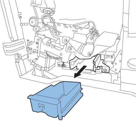
20 Copier B/W imagerunner ADVANCE 8500 series imagerunner ADVANCE 8505, imagerunner ADVANCE 8585, imagerunner ADVANCE 8595 Copier B/W imagerunner ADVANCE 6500 series imagerunner ADVANCE 6555, imagerunner ADVANCE 6565, imagerunner ADVANCE 6575 " Remove all the output paper" is displayed when delivering to the escape tray (Staple Finisher-V1/Booklet Finisher-V2) [Symptom] When delivering to the escape tray in printing or copying, "Remove all the output paper (Remove the paper in the delivery tray)" message may be displayed. [Cause] To install or move the finisher, if the worker holds the position shown in the below photo, the full detection sensor flag [1] is pressed towards the back side with fingers, then it becomes unable to come back to the normal position and ends in the above mentioned symptom. The figure [A] shows a condition where the sensor flag is at a normal position and the figure [B], the sensor flag is pushed towards the back side. 17
![[Service work] When the aforementioned symptom has occurred, perform the work](/docs-images/72/67594521/images/21-0.jpg "following the procedure below. 1) Turn the main power of the main body off.")
![2) Push the delivery roller [2] of the upper escape tray towards the rear side 3)](/docs-images/72/67594521/images/21-1.jpg "Check if the sensor flag [1] comes back to a normal position by its own weight as")
![shown in the figure [A].](/docs-images/72/67594521/images/21-2.jpg "[Attention] When to move a finisher, hold it at its cover area on the rear side as")
21 [Service work] When the aforementioned symptom has occurred, perform the work following the procedure below. 1) Turn the main power of the main body off. 2) Push the delivery roller [2] of the upper escape tray towards the rear side 3) Check if the sensor flag [1] comes back to a normal position by its own weight as shown in the figure [A]. [Attention] When to move a finisher, hold it at its cover area on the rear side as shown in the figure [A]. Be sure not to move the finisher as the below figure [B]. 18
22 Copier B/W imagerunner ADVANCE 8500 series imagerunner ADVANCE 8505, imagerunner ADVANCE 8585, imagerunner ADVANCE 8595 Copier B/W ir-adv 8205/8285/8295 Series imagerunner ADVANCE 8205, imagerunner ADVANCE 8205 PRO, imagerunner ADVANCE 8285, imagerunner ADVANCE 8285 PRO, imagerunner ADVANCE 8295, imagerunner ADVANCE 8295 PRO Copier B/W ir-adv 8105/8095/8085 Series ir ADVANCE 8085, ir ADVANCE 8085 PRO, ir ADVANCE 8105G, ir ADVANCE 8085G, ir ADVANCE 8105, ir ADVANCE 8105 PRO, ir ADVANCE 8095, ir ADVANCE 8095 PRO, ir ADVANCE 8095G Boss breakage in the shutter of patch sensor assembly occurring when opening/closing the shutter [Symptom] In the machines prior to the Countermeasure cut-in serial number in factory described below when opening the shutter [2] in the patch sensor assembly [1], the boss [a] which acts as a supporting point may break. [Cause] Stress caused by opening and closing the shutter applies to the root of the boss intensively for a long time, resulting in the above symptom. [Service work] When the above symptom occurs, refer to Service Manual and replace with the new type patch sensor assembly (FM ) and the shutter (FC ). [Service parts] FC SHUTTER FM PATCH SENSOR ASS'Y 19

![[Symptom] After the main power of main body is turned on, icons may be slow in coming up on the UI screen of the control panel, and also some of the icons may be missed.](/docs-images/72/67594521/images/23-1.jpg "[A]shows the UI screen at the time of the symptom occurs. and [B], the normal UI screen.")
23 Copier B/W imagerunner ADVANCE 8500 series imagerunner ADVANCE 8505, imagerunner ADVANCE 8585, imagerunner ADVANCE 8595 Copier B/W imagerunner ADVANCE 6500 series imagerunner ADVANCE 6555, imagerunner ADVANCE 6565, imagerunner ADVANCE 6575 Not all the icons are displayed on the UI screen of main body due to disconnection of the connectors. [Symptom] After the main power of main body is turned on, icons may be slow in coming up on the UI screen of the control panel, and also some of the icons may be missed. [A]shows the UI screen at the time of the symptom occurs. and [B], the normal UI screen. [Cause] If any of the following connectors is disconnected, communication re-try is repeated between the main controller PCB and the DC controller PCB. In such cases, the UI screen reacts slow and the aforementioned symptom occurs. - The connectors J401 [1] and J442 [2] of the DC controller PCB [A]. - The connector J5202 [3] of the main controller PCB2 [B] and the connector J518 [4] of the relay PCB [C] 20 21
![[Service work] 1) Check to see if the following 4 connectors are not disconnected. If no connector is disconnected, check other factors (disconnection of cable and unit etc.](/docs-images/72/67594521/images/24-0.jpg ") [Reference] Refer to Parts Replacement and Cleaning > \"Removing the DC Controller PCB\", \"Removing Main Controller PCB 2\" and \"Removing the Power Supply Assembly\" in the service manual to get access")
24 [Service work] 1) Check to see if the following 4 connectors are not disconnected. If no connector is disconnected, check other factors (disconnection of cable and unit etc.) [Reference] Refer to Parts Replacement and Cleaning > "Removing the DC Controller PCB", "Removing Main Controller PCB 2" and "Removing the Power Supply Assembly" in the service manual to get access to respective PCBs. 1-1) See if the connectors J401 and J442 of the DC controller PCB are not disconnected. 1-2) See if the connector J5202 of the main controller PCB 2 is not disconnected. 1-3) See if the connector J518 of the relay PCB is not disconnected. 2) Start the main body and confirm that a phenomenon does not occur. 22

![pages may be mixed [1] (Skip Blank Originals fails) even if "Skip Blank Originals" is selected in Scan and Send/Scan and Store (Advanced Box).](/docs-images/72/67594521/images/25-1.jpg "[Cause] If the scanner area is not clean for instance it has foreign particles attached on it, a blank original may be read as streaks in the paper feed direction.")
25 Transmission/Fax-Related Copier B/W imagerunner ADVANCE 8500 series imagerunner ADVANCE 8505, imagerunner ADVANCE 8585, imagerunner ADVANCE 8595 Copier B/W imagerunner ADVANCE 6500 series imagerunner ADVANCE 6555, imagerunner ADVANCE 6565, imagerunner ADVANCE 6575 Skip Blank Originals fails in Scan and Send/Scan and Store due to foreign particles attached to the scanning area [Symptom] Blank pages may be mixed [1] (Skip Blank Originals fails) even if "Skip Blank Originals" is selected in Scan and Send/Scan and Store (Advanced Box). [Cause] If the scanner area is not clean for instance it has foreign particles attached on it, a blank original may be read as streaks in the paper feed direction. In this case, the scanned blank sheet is recognized as an original with streaks in the paper feed direction, therefore the processing to eliminate blank pages by Skip Blank Originals control will not be executed even if "Skip Blank Originals" is selected in Scan and Send/Scan and Store (Advanced Box). The streaks in paper feed direction due to the soiling on the scanning area is erased with image processing after the control of Skip Blank Originals. As a result, a data that includes blank sheets as same as the originals is sent and stored. This is how the above mentioned symptom occurs. [Service work] 1) Select A) or B) according to the type of the originals. A) When the symptom occurs with the first page (upper side) of one-sided originals or double-sided originals A-1) Open the ADF [1] and clean the scanning area (a strip of glass) [2]. [Caution] Do not use any detergent. A-2) Scan the original that generated the symptom and confirm the symptom does not occur. If the symptom no longer occurs, the work is completed. 23
 When the symptom occurs with the second page (under side) of double-sided originals B-1) Pull the lever of the ADF to open the scanning area cover [1] then open the inside cover [2] and clean the")
![scanning area (a strip of glass). [Caution] Do not use any detergent. B-2) Close the inside cover and the scanning area cover those were opened in the step B-1).](/docs-images/72/67594521/images/26-1.jpg "B - 3 ) S c a n t h e o r i g i n a l s t h a t g e n e r a t e d t h e s y m p t o m a n d c o n f i r m t h e s y m p t o m n o l o n g e r o c c u r s.")
26 If the symptom does not improve, go to step 2). B) When the symptom occurs with the second page (under side) of double-sided originals B-1) Pull the lever of the ADF to open the scanning area cover [1] then open the inside cover [2] and clean the scanning area (a strip of glass). [Caution] Do not use any detergent. B-2) Close the inside cover and the scanning area cover those were opened in the step B-1). B - 3 ) S c a n t h e o r i g i n a l s t h a t g e n e r a t e d t h e s y m p t o m a n d c o n f i r m t h e s y m p t o m n o l o n g e r o c c u r s. I f t h e s y m p t o m n o l o n g e r o c c u r s, t h e w o r k i s c o m p l e t e d. I f t h e s y m p t o m d o e s n o t i m p r o v e, g o t o s t e p 2 ). 2) Press "Adjust Recognition Level" of Skip Blank Originals, change the recognition level in "+" direction and press "OK". The change of this setting increases the recognition precision of Skip Blank Originals. [Caution] If the setting of "Adjust Recognition Level" is too high, an original which has only a few characters in low density on it could be recognized as a blank original and then "Skip Blank Originals" is executed. 3) Scan the originals that generated the symptom and confirm the symptom no longer occurs. If the symptom does not improve, check other causes. 24


27 Jam (Main Unit) Copier B/W imagerunner ADVANCE 6500 series imagerunner ADVANCE 6555, imagerunner ADVANCE 6565, imagerunner ADVANCE 6575 Copier B/W ir-adv 6275/6265/6255 Series imagerunner ADVANCE 6275, imagerunner ADVANCE 6275i, imagerunner ADVANCE 6265, imagerunner ADVANCE 6265i, imagerunner ADVANCE 6255, imagerunner ADVANCE 6255i Copier B/W ir-adv 6075/6065/6055 Series ir ADVANCE 6055, ir ADVANCE 6055i, ir ADVANCE 6065, ir ADVANCE 6065i, ir ADVANCE 6075, ir ADVANCE 6075i, ir ADVANCE 6065-R Copier B/W imagerunner ADVANCE 8500 series imagerunner ADVANCE 8505, imagerunner ADVANCE 8585, imagerunner ADVANCE 8595 Copier B/W ir-adv 8205/8285/8295 Series imagerunner ADVANCE 8205, imagerunner ADVANCE 8205 PRO, imagerunner ADVANCE 8285, imagerunner ADVANCE 8285 PRO, imagerunner ADVANCE 8295, imagerunner ADVANCE 8295 PRO Copier B/W ir-adv 8105/8095/8085 Series ir ADVANCE 8085, ir ADVANCE 8085 PRO, ir ADVANCE 8105G, ir ADVANCE 8085G, ir ADVANCE 8105, ir ADVANCE 8105 PRO, ir ADVANCE 8095, ir ADVANCE 8095 PRO, ir ADVANCE 8095G 0108/0215 jam codes due to the coming off of the detection flag of the photo sensor assembly [Symptom] Misalignment of side registration on image and 0108/0215 jam may occur when printing in duplex mode : Duplex Merging Sensor Delay jam 0215 : Duplex Left Sensor Stationary jam [Cause] Although, in rare cases the detection flag holder [1] of the photo sensor assembly is loose. For this reason the detection flag comes off, then the detection does not work properly and results in the above mentioned symptom. [Service work] When the aforementioned symptom has occurred, prepare a new photo sensor assembly (FM ) and replace with it following the procedure below. 1) Referring to Service Manual, remove the fixing feed lever, the fixing feed right front cover, and the fixing feed left cover. 2) Pull out the connector [1] connected to the photo sensor assembly. Then remove 2 screws [2]. 25
28 3) Pull out the photo sensor assembly to the front, and replace it with the new photo sensor assembly. 4) Install the items by reversing the procedure from step 2). [Service parts] No. 1 Part Number Description Old FM PHOTO SENSOR ASS'Y New

 [Symptom] 1004 jam or folded corner of printed out paper may occur on machines with serial")
29 Jam (Delivery options) Copier B/W imagepress 1135/1125/1110 Series imagepress 1135II, imagepress 1135Plus, imagepress 1125II, imagepress 1125Plus, imagepress 1110II, imagepress 1110Plus, imagepress 1110, imagepress 1125, imagepress 1135 Copier B/W ir-adv 8205/8285/8295 Series imagerunner ADVANCE 8205, imagerunner ADVANCE 8205 PRO, imagerunner ADVANCE 8285, imagerunner ADVANCE 8285 PRO, imagerunner ADVANCE 8295, imagerunner ADVANCE 8295 PRO Copier B/W imagerunner ADVANCE 8500 series imagerunner ADVANCE 8505, imagerunner ADVANCE 8585, imagerunner ADVANCE Jam Code or folded corner on printed out paper due to positional displacement of support (Staple/Saddle/Booklet/ Finisher) [Symptom] 1004 jam or folded corner of printed out paper may occur on machines with serial number earlier than the following countermeasure cut-in serial numbers in factory : Shift Unit Trailing Edge Sensor Delay Jam [Cause] When the sliding load from the sliding part [1] inside the side registration sensor assembly is great, the side registration sensor assembly drive motor steps out and the position of the support [2] is displaced towards the front side of the product [a]. In the said condition, the paper contacts the support [2], would be skewed in delivery and may result in the aforementioned symptom. [Service work] When the above mentioned symptom frequents, prepare and replace with the new type side registration sensor assembly for each product referring to the service manual. A) Finisher AK1, Saddle Finisher AK2, Staple Finisher Q1/W1, Booklet Finisher Q1/W1 - SIDE REGIST, SENSOR PCB ASS'Y [1] (FM ) B) Finisher AN1/AF1/AJ1, Saddle Finisher AN2/AF2/AJ2 - SIDE REGIST, SENSOR PCB ASS'Y [2] (FM ) 27
30 [Service parts] A) Finisher AK1, Saddle Finisher AK2, Staple Finisher Q1/W1, Booklet Finisher Q1/W1 No. 1 Part Number Description Q'ty Fig.No. L36 Old FM SIDE REGIST, SENSOR PCB ASS'Y 1->0 New FM SIDE REGIST, SENSOR PCB ASS'Y 0->1 B) Finisher AN1/AF1/AJ1, Saddle Finisher AN2/AF2/AJ2 No. 1 Q'ty Fig.No. Old FM Part Number SIDE REGIST, SENSOR PCB ASS'Y Description 1->0 L36 New FM SIDE REGIST, SENSOR PCB ASS'Y 0->1 28
31 Error Code Copier B/W imagerunner ADVANCE 6500 series imagerunner ADVANCE 6555, imagerunner ADVANCE 6565, imagerunner ADVANCE 6575 Copier B/W ir-adv 6275/6265/6255 Series imagerunner ADVANCE 6275, imagerunner ADVANCE 6275i, imagerunner ADVANCE 6265, imagerunner ADVANCE 6265i, imagerunner ADVANCE 6255, imagerunner ADVANCE 6255i Copier B/W ir-adv 6075/6065/6055 Series ir ADVANCE 6055, ir ADVANCE 6055i, ir ADVANCE 6065, ir ADVANCE 6065i, ir ADVANCE 6075, ir ADVANCE 6075i, ir ADVANCE 6065-R Copier B/W imagerunner ADVANCE 8500 series imagerunner ADVANCE 8505, imagerunner ADVANCE 8585, imagerunner ADVANCE 8595 Copier B/W ir-adv 8205/8285/8295 Series imagerunner ADVANCE 8205, imagerunner ADVANCE 8205 PRO, imagerunner ADVANCE 8285, imagerunner ADVANCE 8285 PRO, imagerunner ADVANCE 8295, imagerunner ADVANCE 8295 PRO Copier B/W ir-adv 8105/8095/8085 Series ir ADVANCE 8085, ir ADVANCE 8085 PRO, ir ADVANCE 8105G, ir ADVANCE 8085G, ir ADVANCE 8105, ir ADVANCE 8105 PRO, ir ADVANCE 8095, ir ADVANCE 8095 PRO, ir ADVANCE 8095G E Caused by the fixing drawer cable breakage [Symptom] E may occur. - E : Fixing Power Supply error [Cause] The fixing drawer cable [1] comes in contact with the sheet metal [a], and the cable coating is broken and short-circuited to cause the above-mentioned symptom. Note: There were cases that short-circuit caused the defective main drive driver PCB assembly and the relay PCB assembly. 29
![[Service work] If the above-mentioned symptom occurs, replace the fixing drawer cable with the new type of the fixing drawer cable](/docs-images/72/67594521/images/32-0.jpg "(FM3-7351-020) having the additional protective tape to prevent the coating breakage.")
32 [Service work] If the above-mentioned symptom occurs, replace the fixing drawer cable with the new type of the fixing drawer cable (FM ) having the additional protective tape to prevent the coating breakage. [Replacement parts] - CABLE, FIXING DRAWER: FM
33 Copier B/W imagerunner ADVANCE 6500 series imagerunner ADVANCE 6555, imagerunner ADVANCE 6565, imagerunner ADVANCE 6575 Copier B/W imagerunner ADVANCE 8500 series imagerunner ADVANCE 8505, imagerunner ADVANCE 8585, imagerunner ADVANCE 8595 E x due to malfunction of the front/rear tray auxiliary guide or coming off of the bearing of lower stack delivery roller (Staple Finisher-V1 / Booklet Finisher-V1) [Symptom] E x may occur during copy operation. - E : Error in the Tray Auxiliary Guide Motor. The tray auxiliary guides don't come off the Front/Rear Tray Auxiliary Guide HP Sensors when the Tray Auxiliary Guide Motor has been driven for 1 second. - E : Error in the Tray Auxiliary Guide Motor. The Front/Rear Tray Auxiliary Guide HP Sensors don't detect the tray auxiliary guides when the Tray Auxiliary Guide Motor has been driven for 1 second. [Cause] Either of the following 2 causes leads to the above mentioned symptom. a) When the rack of the front/rear tray auxiliary guide [1] does not engage properly with the pinion gear [2], this condition has brought malfunction. b) When the clearance of the mounting of the lower stack delivery roller [1] is so wide that the bearing [2] has come off. 31
![The figure below shows a condition where the bearing [1] has come off.](/docs-images/72/67594521/images/34-0.jpg "[Service work] When the aforementioned symptom has occurred, check if the front/rear tray auxiliary guide works properly.")

34 The figure below shows a condition where the bearing [1] has come off. [Service work] When the aforementioned symptom has occurred, check if the front/rear tray auxiliary guide works properly. If the front/rear tray auxiliary guide does not work properly, prepare the washer (XD ), fix the dropped bearing of the lower stack delivery roller and adjust the mounting of the front/rear tray auxiliary guide holder following the procedure below. 1) Remove the stack tray [1]. - 2 screws [2] - 4 hangers [3] 32

35 2) Remove the grate-shaped lower guide. - 2 screws [2] 33
![[Note] Insert the claw [1] as](/docs-images/72/67594521/images/36-0.jpg "shown in the figure for")

36 [Note] Insert the claw [1] as shown in the figure for installation and then hook the rack [2] on the stepped screw. 34
![3) If the bearing [2] of the lower stack delivery roller [1]](/docs-images/72/67594521/images/37-0.jpg "has come off, reattach the bearing [2] in a proper state and")
.")
37 3) If the bearing [2] of the lower stack delivery roller [1] has come off, reattach the bearing [2] in a proper state and go to the step 4). If the bearing [2] has not come off, then go to the step 8). 4) Remove the metal plate [1]. - Screw [2] (x1) 35
![5) Remove the bushing [2] from the lower stack delivery roller [1].](/docs-images/72/67594521/images/38-1.jpg "6) Attach the washer (XD1-1106-235) [3] between the E-ring [1] and the")
38 5) Remove the bushing [2] from the lower stack delivery roller [1]. 6) Attach the washer (XD ) [3] between the E-ring [1] and the bushing [2]. 36
![7) Reattach the metal plate [1].](/docs-images/72/67594521/images/39-0.jpg "- Screw [2] (x1) 8) Loosen the 2 screws")
39 7) Reattach the metal plate [1]. - Screw [2] (x1) 8) Loosen the 2 screws [1]. 37
![9) Rotate the gear [1] in the direction of the arrow with fingers and let the front/rear tray auxiliary guide [2] protrude by approximate 10mm longer.](/docs-images/72/67594521/images/40-0.jpg "10) Reassemble the parts in reverse order from the step 2). 11) Select the motor being subject to the operation check.")
40 9) Rotate the gear [1] in the direction of the arrow with fingers and let the front/rear tray auxiliary guide [2] protrude by approximate 10mm longer. 10) Reassemble the parts in reverse order from the step 2). 11) Select the motor being subject to the operation check. Go to Service mode (Level1) SORTER > FUNCTION > MTR-CHK, enter "17" and press [OK]. [Reference] The tray auxiliary guide motor (M109) will be selected by entering "17". 12) From Service mode (Level1) SORTER > FUNCTION > MTR-ON, press [OK] to drive the tray auxiliary guide motor (M109) and check the operation of the tray auxiliary guide. 38


41 Copier B/W imagerunner ADVANCE 6500 series imagerunner ADVANCE 6555, imagerunner ADVANCE 6565, imagerunner ADVANCE 6575 Copier B/W imagerunner ADVANCE 8500 series imagerunner ADVANCE 8505, imagerunner ADVANCE 8585, imagerunner ADVANCE 8595 E and abnormal noise from the reader assembly during the operation due to the detached flat cable unit [Symptom] E and abnormal noise from the reader assembly during the operation may occur on the products with the serial numbers earlier than those listed in Countermeasure cut-in serial number in factory below. - E : Reader Scanner Unit HP error [Cause] If the scanner fixation tool [1] is inserted obliquely when moving the main body, the tool becomes in a state where it is pressing the flat cable unit [2]. If the main body is moved in this state, the flat cable unit [2] may be detached, which may cause the above-mentioned symptom. Fig.[A] shows the state where the scanner fixation tool [1] is inserted in a correct and straight way. Fig.[B] shows the state where the scanner fixation tool [1] is inserted in a wrong and oblique way. [Service work] If the above-mentioned symptom occurs, check whether the flat cable unit is detached from the reader scanner unit. If it is detached, attach the flat cable unit correctly. In addition, if the fixing claw [a] of the flat cable unit is broken, replace it with the new flat cable unit (FM ). 39
![[Attention] If attaching the scanner fixation tool when moving the main body, insert it in a correct and straight](/docs-images/72/67594521/images/42-0.jpg "way. [Service parts] No. 1 Part Number Old FM0-0482-000 Description FLAT CABLE UNIT New 40 Q'ty Fig.No. 1 -> 1 D12")
42 [Attention] If attaching the scanner fixation tool when moving the main body, insert it in a correct and straight way. [Service parts] No. 1 Part Number Old FM Description FLAT CABLE UNIT New 40 Q'ty Fig.No. 1 -> 1 D12

![ADVANCE 6065, ir ADVANCE 6065i, ir ADVANCE 6075, ir ADVANCE 6075i, ir ADVANCE 6065-R E840-0001 due to the defect securing screws for the fixing shutter motor [Symptom] In the machines prior to the](/docs-images/72/67594521/images/43-1.jpg "Countermeasure cut-in serial number in factory described below E840-0001 may occur.")
43 Copier B/W imagerunner ADVANCE 6500 series imagerunner ADVANCE 6555, imagerunner ADVANCE 6565, imagerunner ADVANCE 6575 Copier B/W ir-adv 6275/6265/6255 Series imagerunner ADVANCE 6275, imagerunner ADVANCE 6275i, imagerunner ADVANCE 6265, imagerunner ADVANCE 6265i, imagerunner ADVANCE 6255, imagerunner ADVANCE 6255i Copier B/W ir-adv 6075/6065/6055 Series ir ADVANCE 6055, ir ADVANCE 6055i, ir ADVANCE 6065, ir ADVANCE 6065i, ir ADVANCE 6075, ir ADVANCE 6075i, ir ADVANCE 6065-R E due to the defect securing screws for the fixing shutter motor [Symptom] In the machines prior to the Countermeasure cut-in serial number in factory described below E may occur. E : Fixing Shutter Motor error [Cause] The screws securing the fixing shutter motor are loosened and come off after some endurance time has elapsed and from vibration, then the fixing shutter motor becomes unable to be driven the fixing shutter and ends in the above mentioned symptom. [Service work] When the above mentioned symptom has occurred, replace the screws that are securing the fixing shutter motor with the screw with washer (XB ) referring to the service manual. The Fig.[A] shows the previous screw and Fig.[B], the screw with washer to be replaced with. 1) Pull out the Fixing Feed Unit. 2) Remove the Fixing Front Cover and the Fixing Drive Unit 1. 3) Replace the 2 screws [2] that are securing the fixing shutter motor [1] with the screw with washer (XB ). The Fig.[C] shows the securement with the previous screw and Fig.[D], with the screw with washer
. [Service parts] XB2-8301-009 SCREW,W/WASHER,M3X10")
44 4) Reassemble the parts in reverse order from the step 2). [Service parts] XB SCREW,W/WASHER,M3X10 43

45 Copier B/W imagerunner ADVANCE 4500 Series imagerunner ADVANCE 4525, imagerunner ADVANCE 4525F, imagerunner ADVANCE 4525i, imagerunner ADVANCE 4535, imagerunner ADVANCE 4535F, imagerunner ADVANCE 4535i, imagerunner ADVANCE 4545, imagerunner ADVANCE 4545F, imagerunner ADVANCE 4545i, imagerunner ADVANCE 4551, imagerunner ADVANCE 4551i Copier B/W imagerunner ADVANCE 6500 series imagerunner ADVANCE 6555, imagerunner ADVANCE 6565, imagerunner ADVANCE 6575 Copier B/W imagerunner ADVANCE 8500 series imagerunner ADVANCE 8505, imagerunner ADVANCE 8585, imagerunner ADVANCE 8595 E /E due to malfunction of the front/rear tray auxiliary guides(staple/booklet Finisher_V1) [Symptom] In the machines prior to the countermeasure cut-in serial number in factory described below E or E may occur. - E : Error in the Tray Auxiliary Guide Motor. The tray auxiliary guides don't come off the Front/Rear Tray Auxiliary Guide HP Sensors when the Tray Auxiliary Guide Motor has been driven for 1 second. - E : Error in the Tray Auxiliary Guide Motor. The Front/Rear Tray Auxiliary Guide HP Sensors don't detect the tray auxiliary guides when the Tray Auxiliary Guide Motor has been driven for 1 second. [Cause] Due to the following 2 operation failure of the front/rear tray auxiliary guide, the above-mentioned symptom occurs. 1) Operation failure of the front/rear tray auxiliary guide due to shift in engagement of the rack and the pinion [2] of the front/rear tray auxiliary guide [1] 2) Operation failure of the front/rear tray auxiliary guide due to large clearance of the mount of the lower delivery roller [1] dislocating the bushing [2] on the rear side. [Service work] If the above-mentioned symptom occurs, check whether the front/rear tray auxiliary guide operates normally. If the front/rear tray auxiliary guide does not operate normally, prepare the washer (XD ), modify the bushing of the lower delivery roller and adjust the assembly of the front/rear tray auxiliary guide holder by following the procedures below. 45 4
 is not necessary.")
![1) Remove the stack tray [1] and the grate-shaped lower guide [2] by](/docs-images/72/67594521/images/46-1.jpg "referring to the Service Manual.")
![2) If the bushing [2] on the rear side of the lower delivery roller](/docs-images/72/67594521/images/46-2.jpg "[1] is detached from the supporting plate, go to the step 3).")
![If the bushing [2] is not detached, go to the step 7).](/docs-images/72/67594521/images/46-3.jpg "3) Remove the supporting plate [1] of the bushing on the near side.")
46 However, in case of replacement by the new-type lower delivery roller, washer (XD ) is not necessary. 1) Remove the stack tray [1] and the grate-shaped lower guide [2] by referring to the Service Manual. 2) If the bushing [2] on the rear side of the lower delivery roller [1] is detached from the supporting plate, go to the step 3). If the bushing [2] is not detached, go to the step 7). 3) Remove the supporting plate [1] of the bushing on the near side. - Screw [2] 1 pcs 4) Remove the busing [2] from the lower delivery roller shaft [1]. 46
![5) Attach the washer (XD1-1106-235) [3] between the E-ring [1] and the bushing [2] of the lower delivery roller However, if the lower delivery roller is a new type, attaching the washer](/docs-images/72/67594521/images/47-1.jpg "(XD1-1106-235) [3] is not required. 6) While attaching the bushing on the rear side of the lower delivery roller, attach the supporting plate [1] which was removed in the step 3).")
47 5) Attach the washer (XD ) [3] between the E-ring [1] and the bushing [2] of the lower delivery roller However, if the lower delivery roller is a new type, attaching the washer (XD ) [3] is not required. 6) While attaching the bushing on the rear side of the lower delivery roller, attach the supporting plate [1] which was removed in the step 3). Screw [2] 1 pcs 7 ) Loosen the 2 screws [1], rotate the gear [2] in an arrow direction with a hand, pull out the front/rear tray auxiliary guide [3] for approx. 10 mm, and then tighten the 2 screws [1]. 8) Assemble the parts by reversing the step 1). 9 ) Select the motor to check operation. Service Mode (Level1) SORTER > FUNCTION > MTR-CHK enter "17" and press "OK". [Reference] After "17" is entered, the tray auxiliary guide motor (M109) is selected. 10) Service Mode (Level1) SORTER > FUNCTION > MTR-ON press "OK" to drive the tray auxiliary guide motor (M109) and check the operation of the tray auxiliary guide. [Service parts] No. 1 2 Part Number Description Q'ty Old FM1-H ROLLER, DELIVERY,LOWER 1->0 New FM1-H ROLLER, DELIVERY,LOWER 0->1 L20 L20 Old New Fig.No. XD RETAINING RING (E-TYPE) 47 0->1

48 Copier B/W ir-adv 6075/6065/6055 Series ir ADVANCE 6055, ir ADVANCE 6055i, ir ADVANCE 6065, ir ADVANCE 6065i, ir ADVANCE 6075, ir ADVANCE 6075i, ir ADVANCE 6065-R Copier B/W ir-adv 6275/6265/6255 Series imagerunner ADVANCE 6275, imagerunner ADVANCE 6275i, imagerunner ADVANCE 6265, imagerunner ADVANCE 6265i, imagerunner ADVANCE 6255, imagerunner ADVANCE 6255i Copier B/W imagerunner ADVANCE 6500 series imagerunner ADVANCE 6555, imagerunner ADVANCE 6565, imagerunner ADVANCE 6575 Copier B/W ir-adv 8105/8095/8085 Series ir ADVANCE 8085, ir ADVANCE 8085 PRO, ir ADVANCE 8105G, ir ADVANCE 8085G, ir ADVANCE 8105, ir ADVANCE 8105 PRO, ir ADVANCE 8095, ir ADVANCE 8095 PRO, ir ADVANCE 8095G Copier B/W ir-adv 8205/8285/8295 Series imagerunner ADVANCE 8205, imagerunner ADVANCE 8205 PRO, imagerunner ADVANCE 8285, imagerunner ADVANCE 8285 PRO, imagerunner ADVANCE 8295, imagerunner ADVANCE 8295 PRO Copier B/W imagerunner ADVANCE 8500 series imagerunner ADVANCE 8505, imagerunner ADVANCE 8585, imagerunner ADVANCE 8595 E /E /E /E x/E caused by damaged coating of the fixing drawer cable [Symptom] E /E /E /E x/E may occur in the main body earlier than the countermeasure cut-in serial numbers in factory mentioned below. (x=4 or 7) - E : Fixing Power Supply error (Detect that the Fixing Main Thermistor is not connected.) - E : Serial communication error - E : Current Sensor error - E : Fixing Power Supply error (Detected OFF with output 12 V of the Main Driver PCB.) - E : Fixing Power Supply error (An error in voltage inside the Fixing Power Supply PCB was detected.) [Cause] If a vibration is loaded to the fixing drawer cable (FM3-7351) on the back side of the main body or if the fixing/feeding assembly is removed and installed while the fixing drawer cable (FM3-7351) is pinched by the duct, the coating of the cable may be damaged, and this will lead to the above mentioned symptoms. [Service work] When the aforementioned symptoms have occurred and if the device will not be restored even after performing the usual error release operation, check for the wire pinching on the fixing drawer cable. If the cable is damaged, prepare and replace with the new type fixing drawer cable (FM ) [1]. 48
49 [Service parts] No. 1 Part Number Description Q'ty Old FM CABLE, FIXING DRAWER 1 -> 0 New FM CABLE, FIXING DRAWER 0 -> 1 49 Fig.No. 104A

50 Copier B/W ir-adv 6075/6065/6055 Series ir ADVANCE 6055, ir ADVANCE 6055i, ir ADVANCE 6065, ir ADVANCE 6065i, ir ADVANCE 6075, ir ADVANCE 6075i, ir ADVANCE 6065-R Copier B/W ir-adv 6275/6265/6255 Series imagerunner ADVANCE 6275, imagerunner ADVANCE 6275i, imagerunner ADVANCE 6265, imagerunner ADVANCE 6265i, imagerunner ADVANCE 6255, imagerunner ADVANCE 6255i Copier B/W imagerunner ADVANCE 6500 series imagerunner ADVANCE 6555, imagerunner ADVANCE 6565, imagerunner ADVANCE 6575 Copier B/W ir-adv 8105/8095/8085 Series ir ADVANCE 8085, ir ADVANCE 8085 PRO, ir ADVANCE 8105G, ir ADVANCE 8085G, ir ADVANCE 8105, ir ADVANCE 8105 PRO, ir ADVANCE 8095, ir ADVANCE 8095 PRO, ir ADVANCE 8095G Copier B/W ir-adv 8205/8285/8295 Series imagerunner ADVANCE 8205, imagerunner ADVANCE 8205 PRO, imagerunner ADVANCE 8285, imagerunner ADVANCE 8285 PRO, imagerunner ADVANCE 8295, imagerunner ADVANCE 8295 PRO Copier B/W imagerunner ADVANCE 8500 series imagerunner ADVANCE 8505, imagerunner ADVANCE 8585, imagerunner ADVANCE 8595 E due to the worn coating of paper pick-up assembly cable [Symptom] E may occur. - E : Serial communication error [Cause] If the cable is in contact with the roller spindle for the pick-up assembly [1] and its coating is worn, a short circuit occurs and it results in the above-mentioned symptom. Photo [A] shows the state of that bent cable is in contact with the roller spindle. Photo [B] shows the normal state of that the cable is placed straight. [Service work] When the above symptom occurs, check the cable adjacent to the roller spindle for paper pick-up assembly. If the coating of cable has worn, the replacement of paper pick-up assembly or cable is required. If the coating of cable has not worn, check for the other causes. [Service parts] - PAPER PICK-UP ASS'Y, RIGHT : FM PAPER PICK-UP ASS'Y, LEFT : FM CABLE, PAPER PICK-UP ASS'Y : FM CABLE, DECK PICK-UP, LEFT : FM
![Specifications-Related Regarding the replacing operation of photo-interrupter (shift tray - D1/E1/F1) [Detail] In the machines prior to the Countermeasure cut-in serial number in factory described](/docs-images/72/67594521/images/51-0.jpg "below the photo-interrupter used for the sift tray assembly of shift trayd1/ E1/ F1 each (total number of the photo-interrupters is 3) is changed for supply reason.")
51 Specifications-Related Regarding the replacing operation of photo-interrupter (shift tray - D1/E1/F1) [Detail] In the machines prior to the Countermeasure cut-in serial number in factory described below the photo-interrupter used for the sift tray assembly of shift trayd1/ E1/ F1 each (total number of the photo-interrupters is 3) is changed for supply reason. - Old type : Photo-interrupter (FK ) - New type : Photo-interrupter (WG ) When the photo-interrupter or a related part is replaced in accordance with this change, please follow [Servicing Work] set forth below. [Service work] a) For shift tray -D1 a-1) When the photo-interrupter [1] or [4] for old type shift tray -D1 is replaced individually, use old type photointerrupter (FK ). a-2) When the photo-interrupter [1] or [4] for new type shift tray -D1 is replaced individually, use new type photointerrupter (WG ). a-3) When the replacement of photo-interrupter [1] on the tray assembly [2] is needed, the replacement of tray assembly [2] (FM ) is also available instead of the replacement of photo-interrupter [1]. a-4) The sensor cover [3] goes out of use. When the replacement of sensor cover [3] is required due to its damage or another reason, prepare and replace the tray assembly [2] (FM ). b) For shift tray -E1 b-1) When the photo-interrupter [1] or [4] for old type shift tray -E1 is replaced individually, use old type photointerrupter (FK ). b-2) When the photo-interrupter [1] or [4] for new type shift tray -E1 is replaced individually, use new type photo-interrupter (WG ). b-3) When the replacement of photo-interrupter [1] on the tray assembly [2] is needed, the replacement of tray assembly [2] (FM ) is also available instead of the replacement of photo-interrupter [1]. b-4) The sensor cover [3] goes out of use. When the replacement of sensor cover [3] is required due to its damage or another reason, prepare and replace the tray assembly [2] (FM ). c) For shift tray -F1 c-1) All shift tray-f1 are manufactured with new type photo-interrupter (WG ) [1] and [4]. When the photo-interrupter [1] or [4] is replaced individually, make sure to use new type photo-interrupter (WG ). c-2) The sensor cover [3] goes out of use. When the replacement of sensor cover [3] is required due to its damage or another reason, prepare the tray assembly [2] (FM1-J ) which has been set up as a new service part and then replace the original tray assembly with the new type tray assembly. 51
![[Service parts] Shift Tray-D1 No. 1 2 Part Number Description Old FK2-0149-000 Photo-interrupter New WG8-5783-000 Photo-interrupter Old FB5-7585-000 Sensor cover New Shift Tray-E1 No.](/docs-images/72/67594521/images/52-0.jpg "1 2 Part Number Description Old FK2-0149-000 Photo-interrupter New WG8-5783-000 Photo-interrupter Old FB5-7585-000 Sensor cover New 3 Old FC9-8294-000 Shift tray New FM4-5078-000 Tray Assembly Shift")
52 [Service parts] Shift Tray-D1 No. 1 2 Part Number Description Old FK Photo-interrupter New WG Photo-interrupter Old FB Sensor cover New Shift Tray-E1 No. 1 2 Part Number Description Old FK Photo-interrupter New WG Photo-interrupter Old FB Sensor cover New 3 Old FC Shift tray New FM Tray Assembly Shift Tray-F1 No. 1 2 Part Number Description Old FK Photo-interrupter New WG Photo-interrupter Old FB Sensor cover New 3 Old FE Shift tray New FM1-J Tray Assembly 52
HP LaserJet Pro M401/M425MFP Printer Series Continuous Paper Jams, Possible Noises and/or Broken Parts in Toner Cartridge Area
 HP LaserJet Pro M401/M425MFP Printer Series Continuous Paper Jams, Possible Noises and/or Broken Parts in Toner Cartridge Area Users may report that new-out-of-box or lightly used devices continuously
SERVICE MANUAL AND PARTSLIST
 SERVICE MANUAL AND PARTSLIST Next 20 CONTENTS WHAT TO DO WHEN... 1~3 SERVICE ACCESS FACE COVER... 4 TOP COVER... 4 BASE COVER... 5 REAR COVER... 6 FRONT COVER... 7 MECHANICAL ADJUSTMENT NEEDLE THREAD TENSION...
SERVICE MANUAL PARTS LIST MODEL: NH40
 SERVICE MANUAL & PARTS LIST MODEL: NH40 CONTENTS What to do when... 1-3 SERVICE ACCESS Face Cover... 4 Bed Cover... 5 Free-arm Cover... 6 Front Cover... 7 Rear Cover... 8 MECHANICAL ADJUSTMENT Presser
SERVICE MANUAL MODEL: 13512, 14412, 15312
 SERVICE MANUAL MODEL: 13512, 14412, 15312 CONTENTS TROUBLESHOOTING... 1-3 SERVICE ACCESS (1) FACE COVER, BELT COVER... 4 SERVICE ACCESS (2) BASE PLATE... 5 SERVICE ACCESS (3) FRONT COVER... 6 SERVICE ACCESS
FOLDING POCKET DOOR SYSTEM ALT-F Installation Manual
 FOLDING POCKET DOOR SYSTEM ALT-F Installation Manual Thank you for selecting our product. Before starting installation, please read this manual thoroughly to ensure correct installation. Please keep this
FP L75 PARTS CATALOG
 FP L PARTS CATALOG Canon FAXPHONE L FIGURE PACKAGE CONTENTS FIGURE COVERS & TRAY ASS Y 0 0 0 0 0 - HB--000 TRAY, SUPPORT () HB--000 TRAY, MULTI-PURPOSE HB-0-000 COVER, MULTI-PURPOSE TRAY HB--000 SUPPORT,
SERVICE MANUAL MANUAL NO. CSX300-UM-251 CSX300-UM
 00-0 SERVICE MANUAL MANUAL NO. CSX00-UM- CSX00-UM-0-0 HISTORY OF REVISIONS No. Date issued Description of revision Page Edition 0.0. First Printing. All 0 CSX00-UM--0 i CSX00-UM--0 ii CONTENTS. OVERVIEW...-.
1 of 2 3/3/2017 4:49 PM
 1 of 2 3/3/2017 4:49 PM Front Door Window, Assembly Overview 1 - Window guide - Inserted on flange 2 - Door 3 - Inner window recess seal - Inserted on flange 4 - Bolt - 20 Nm 5 - Carrier assembly - Window
OKI C911 / 931 / 941
 OKI C911 / 931 / 941 Disassembly & Reassembly Procedures Distributed at the Oki Data C900 Series Service Classes Oki Data Training Department REV. 1.60 2000 Bishops Gate Blvd. Mt. Laurel, NJ 08054 Copyright
INSTALLATION MANUAL MX-4140N/5140N MX-4141N/5141N DIGITAL FULL COLOR MULTIFUNCTIONAL SYSTEM MODEL SHARP CORPORATION
 INSTALLATION MANUAL DIGITAL FULL COLOR MULTIFUNCTIONAL SYSTEM MODEL MX-4140N/5140N MX-4141N/5141N Parts marked with " " are important for maintaining the safety of the set. Be sure to replace these parts
fi-6130 / fi-6230 Cleaning and Maintenance
 fi-6130 / fi-6230 Cleaning and Maintenance fi-6130 / fi-6230 Cleaning and Maintenance fi-6130 / fi-6230 Image Scanner Operator's Guide Chapter 4 DAILY CARE This chapter describes how to clean the scanner.
PRINTER REPAIR ARTICLE HP LJ 4345/M4345 Swing Plate Replacement
 a1 output bin a2 DUPLEXER a4 FORMATTER COVER a5 FORMATTER a3 fuser entr. guide PRINTER REPAIR ARTICLE HP LJ 4345/M4345 Swing Plate Replacement Grinding noise near the fuser means it is time to replace
Operator s Guide. Sequin Device. Version 1.3. Published by: ZSK Stickmaschinen GmbH - Dokumentation - D Krefeld-Gartenstadt
 Operator s Guide Sequin Device Version 1.3 Published by: ZSK Stickmaschinen GmbH - Dokumentation - D-47800 Krefeld-Gartenstadt Magdeburger Str. 38 40 04 by ZSK, Printed in Germany Subject to change. 04
3.2.3 Rear Door Window and Quarter Window Carrier Assembly
 Tighten all bolts. Tighten bolts marked -1- and -2- in specified sequence. Tightening torque: 8 Nm Remaining bolts can be tightened in any sequence. Insert door window -3- through window recess without
SERVICING MANUAL 419S/423S
 SERVICING MANUAL 415 419S/423S TROUBLESHOOTING PROBLEM CAUSE REMEDY REFERENCE 1. SKIPPING 1. NEEDLE IS NOT INSERTED INSERT THE NEEDLE PROPERLY. STITCHES PROPERLY. 2. NEEDLE IS BENT OR WORN. CHANGE THE
Door window. Front door window, assembly overview
 64-50 Door window Front door window, assembly overview 1 - Window channel Pushed onto flange 2 - Door window Removing Page 64-52 Adjusting Page 64-53 3 - Door 4 - Outer window channel Pushed onto flange
COLOR LASERJET PRO MFP. Repair Manual
 OK COLOR LASERJET PRO MFP Repair Manual X M76 M77 HP Color LaserJet Pro MFP M76, M77 Repair Manual Copyright and License 03 Copyright Hewlett-Packard Development Company, L.P. Reproduction, adaptation,
FD 125 Large-Format Card Cutter
 FD 125 Large-Format Card Cutter 3/201 OPERATOR MANUAL Page 2 Table of Contents SAFETY PRECAUTIONS... 4 Introduction... 5 Specifications... 5 Accessories... 5 Major Components and Assemblies... 6 Control
Assembly locations. Document feeder assembly. Printer door. assembly. Upper guide. assembly. Control panel assembly. Feed assembly
 Assembly locations Document feeder assembly Printer door assembly Upper guide assembly Control panel assembly Feed assembly Electrical components Figure 83. Assembly locations EN Assembly locations 205
AutoSeal FD 2006IL / FE 2006IL
 AutoSeal FD 2006IL / FE 2006IL FI / FJ Series 06/2018 OPERATOR MANUAL First Edition TABLE OF CONTENTS DESCRIPTION 1 SPECIFICATIONS 1 UNPACKING 1 SETUP 2 Sealer Alignment Base Setup 2 Sealer Setup 2-4
fi 5120C / fi 5220C Cleaning and Maintenance
 fi-50c / fi-50c Cleaning and Maintenance fi 50C / fi 50C Cleaning and Maintenance This chapter describes how to clean the scanner. WARNING When operating the scanner, the ADF's glass becomes very hot.
MX-7090N MX-8090N Administrator Machine Adjustment Guide
 MX-7090N MX-8090N Administrator Machine Adjustment Guide Please keep the manual in a safe place where it will not be lost. Caution Machine Adjustment access is provided assuming that an administrative
FD 1202 AutoSeal Tabletop Pressure Sealer
 FD 1202 AutoSeal Tabletop Pressure Sealer 4/2015 OPERATOR MANUAL FIRST EDITION TABLE OF CONTENTS TOPIC PAGE SPECIFICATIONS 1 UNPACKING, COMPONENTS 2 SET-UP 3 OPERATION 5 DETERMINING FOLD TYPE 6 ADJUSTING
REPAIR INSTRUCTIONS. Cat. No Cat. No MILWAUKEE ELECTRIC TOOL CORPORATION. SDS Max Demolition Hammer. SDS Max Rotary Hammer
 Cat. No. 9-0 SDS Max Demolition Hammer Cat. No. -0 SDS Max Rotary Hammer MILWAUKEE ELECTRIC TOOL CORPORATION W. LISBON ROAD BROOKFIELD, WISCONSIN 00-0 8-9-0 d 000 8-9-0 d Special Tools Require Forcing
FD50-H SLIDING DOOR SYSTEM Installation Manual (Ceiling Mount Type for Pocket Door, with Dual Soft Close) Part No.FD50DHCP-PD
 Part No.FD50DHCP-PD") FD50-H SLIDING DOOR SYSTEM Installation Manual (Ceiling Mount Type for Pocket Door, with Dual Soft Close) Part No.FD50DHCP-PD Thank you for purchasing Sugatsune products. Read the instructions carefully
FD50-H SLIDING DOOR SYSTEM Installation Manual (Ceiling Mount Type for Pocket Door, with Dual Soft Close) Part No.FD50DHCP-PD Thank you for purchasing Sugatsune products. Read the instructions carefully
Table of Contents. Paper Jam Clearance 2
 TABLE OF CONTENTS Table of Contents Paper Jam Clearance 2 Paper Jams at the Top Left Cover 3 Paper Jams at the Left Center Cover 4 Paper Jams at the Bottom Left Cover 4 Paper Jams in Trays 1 to 4 5 Paper
Lexmark X94x Clearing Jams Guide
 Lexmark X94x Clearing Jams Guide Clearing jams Avoiding jams The following hints can help you avoid jams: Use only recommended paper or specialty media. For more information, see the Card Stock & Label
Written By: Philip Le Riche
 HP Photosmart D5160 printer Disassembly This guide covers disassembly in order to ease the cover-open linkage or to remove the main logic board for inspection or maintenance. Disassembly and maintenance
Authorized Dealer Canada. BUY the 93M PAPER AND LETTER FOLDER - Click Here 93M. Paper Folder
 BUY the 93M PAPER AND LETTER FOLDER - Click Here 93M Paper Folder Safety Precautions Please read these operating instructions before putting the machine into operation and observe the safety precautions.
FD 2002IL AutoSeal System
 FD 2002IL AutoSeal System 4/2017 OPERATOR MANUAL FIRST EDITION TABLE OF CONTENTS DESCRIPTION 1 SPECIFICATIONS 1 UNPACKING 1 SETUP 2 Sealer Alignment Base Setup 2 Sealer Setup 2-4 Printer Alignment Base
 2705 03-09 99 98 97 82 88 89 83 84 85 86 87 101 103 100 106 81 71 105 104 73 74 75 76 77 78 80 79 57 62 58 56 63 65 66 67 68 64 69 70 59 60 61 31 30 29 32 34 35 41 40 42 36 37 38 39 43 4445 46 33 55 54
MANUAL PLASTIC STRAPPING TOOL MODEL P404
 OPERATION MANUAL / SPARE PARTS LIST MANUAL PLASTIC STRAPPING TOOL MODEL P404 43.0404.02 43040402.en/MAS/ 12.05 INDEX PAGE 1 SAFETY INSTRUCTIONS 2 2 TECHNICAL DATA 3 3 OPERATION ELEMENTS 4 4 ADJUSTMENT
Installation Manual Porter Road, Sarasota FL fax
 072015 Installation Manual BEFORE YOU BEGIN: Read these instructions completely and carefully. FOR YOUR SAFETY: Read and observe all CAUTIONS and WARNINGS shown throughout these instructions. Risk of injury.
FBX1104P FBX1104 FBX1106P FBX1106
 FBX1104P FBX1104 FBX1106P FBX1106 Second edition : September 2004 No. 040037 INTRODUCTION Thank you for your purchasing Kansai Special's FBX Series. Read and study this instruction manual carefully before
TS5-1600AMF MIMAKI ENGINEERING CO., LTD.
 TS5-1600AMF MIMAKI ENGINEERING CO., LTD. TKB Gotenyama Building, Kitashinagawa, Shinagawa-ku, Tokyo 141-0001, Japan Phone: +81-3-5420-8671 Fax: +81-3-5420-8687 URL: http: // www. mimaki. co. jp D201931-10
Astro-Physics Inc. 400QMD Lubrication/Maintenance Guide
 Astro-Physics Inc. 400QMD Lubrication/Maintenance Guide The following guidelines should be followed to lubricate the three main parts of the 400QMD mount. The QMD stands for Quartz Micro-Drive controller.
FBX-PA-2AC. Third edition : April No
 FBX-PA-2AC Third edition : April 2006 No. 060058 INTRODUCTION Thank you very much for purchasing Kansai Special FBX series. Read and study this Instruction Manual carefully before you start any of the
OPERATION MANUAL MBM 207M MANUAL FOLDER
 OPERATION MANUAL MBM 207M MANUAL FOLDER 1-800-223-2508 www.mbmcorp.com 1 Safety Instructions Definition of Symbols and Notes The following names and signs stand for possible dangers: Danger This symbol
Aluminum Frame Type Instruction Manual
 Aluminum Frame TypeInstruction Manual Thank you for selecting our product. Before starting installation, please read this manual thoroughly to ensure correct installation. Please keep this manual at hand
Lexmark X65x Clearing Jams Guide
 Lexmark X65x Clearing Jams Guide Clearing jams Avoiding jams The following hints can help you avoid jams. Paper tray recommendations Make sure the paper lies flat in the tray. Do not remove trays while
LED Thin Frame Fixed Frame Screen User Guide
 LED Thin Frame Fixed Frame Screen User Guide INTRODUCTION INTRODUCTION WARNING - Sharp Edges This product may contain sharp edges, please handle with care. Protective gloves are recommended. WARNING -
DIGITAL MULTIFUNCTIONAL SYSTEM
 MODEL: MX-M850 MX-M950 MX-M00 DIGITAL MULTIFUNCTIONAL SYSTEM Maintenance Guide REGULAR MAINTENANCE REPLACING SUPPLIES REMOVING MISFEEDS REMOVING STAPLE JAMS Keep this manual close at hand for reference
Removing and Replacing the Y-truck
 Service Documentation Removing and Replacing the Y-truck To remove and replace the Y-truck you will need the following tools: 4mm Allen wrench 12mm stamped flat wrench #2 Phillips screwdriver (magnetic
MULTIFUNCTIONAL DIGITAL COLOR SYSTEMS. Copying Guide. 550c/650c/750c
 MULTIFUNCTIONAL DIGITAL COLOR SYSTEMS Copying Guide 550c/650c/750c 009 KYOCERA MITA Corporation All rights reserved Preface How to read this manual Thank you for purchasing Multifunctional Digital Color
Jam Code. Jam Type Jam types are shown below. Error Code > Jam Code > Jam Type Stationary jam Double feed detection.
 Jam Code Jam Type Jam types are shown below. Error Code > Jam Code > Jam Type -80 Type DELAY STNRY OVERLAP TIMING NG OHP NG ADF OP COVER OP RESIDUAL PICKUP NG POWER ON DOOR OP SEQ NG DELAY ESC OTH JAM
HP LaserJet M2727 MFP Series Maintenance
 HP LaserJet M2727 MFP Series Maintenance Fill Paper Trays Load paper and print media Tray 1 1 Tray 1 is accessed from the front of the product. Tray 1 holds up to 50 sheets of 75 g/m 2 (20 lb) media or
FORMAX. FD1400 AutoSeal MAINTENANCE MANUAL FIRST EDITION 11/2007
 FORMAX FD1400 AutoSeal 11/2007 MAINTENANCE MANUAL FIRST EDITION Table of Contents 1400 Shown with Optional Stand Page: 1. Description / Unpacking and Set up 2. Controls / Operation 3. Fold Plate Adjustment
How to remove Jammed Paper
 How to remove Jammed Paper MC760/MC770/MC780 ES7470/ES7480 Rev.1 Paper Jams Paper jams occasionally occur due to paper misfeeding from a paper tray or at any point on the paper path through the printer.
Operating Instructions
 Operating Instructions Holding the material against the angle gauge slide it into the forming head. Be sure that the material remains against the gauge until work is finished. NOTE: This machine will handle
Tapping Screw (W/Flange) 46 Cord Armor 47 Tube (D) 48 Cord. 45 Cord Clip. Tapping Screw (W/Flange) 10 Gear Cover Ass'y. 12 Socket (B) Ass'y
 46 Cord Armor 47 Tube (D) 48 Cord. 45 Cord Clip. Tapping Screw (W/Flange) 10 Gear Cover Ass'y. 12 Socket (B) Ass'y") W8VB The exploded assembly drawing should be used only for authoized service center. W8VB Item No. Part time 1 Magnetic Hex. Socket 2 Sub Stopper 3 O-Ring (S-16) 4 Locator (A) 5 Lock Sleeve (A) 6 O-Ring
W8VB The exploded assembly drawing should be used only for authoized service center. W8VB Item No. Part time 1 Magnetic Hex. Socket 2 Sub Stopper 3 O-Ring (S-16) 4 Locator (A) 5 Lock Sleeve (A) 6 O-Ring
CONTENTS. LOCATE AND IDENTIFYTHE PARTS... WlNDTHE BOBBIN... PREPARE YOUR TOP THREAD... WHAT TO DO WH EN...
 SERVICE MANUAL SEWING MACHINE MODEL 385.11206300 MARCH, 2003 CONTENTS LOCATE AND IDENTIFYTHE PARTS... WlNDTHE BOBBIN... PREPARE YOUR TOP THREAD... WHAT TO DO WH EN... 1 2 3 4-6 SERVICE ACCESS FACE COVER...
Written By: Adam O'Camb
 iphone XR Display Assembly Replacement Replace a cracked or faulty LCD screen in your iphone XR. Written By: Adam O'Camb ifixit CC BY-NC-SA www.ifixit.com Page 1 of 23 INTRODUCTION If your iphone XR screen
1. Turn off or disconnect power to unit (machine). 2. Push IN the release bar on the quick change base plate. Locking latch will pivot downward.
. 2. Push IN the release bar on the quick change base plate. Locking latch will pivot downward.") Figure 1 Miniature Quick Change Applicators, of the end feed type, are designed to crimp end feed strip terminals to prestripped wires. Each applicator is set up to accept the strip form of certain specific
Figure 1 Miniature Quick Change Applicators, of the end feed type, are designed to crimp end feed strip terminals to prestripped wires. Each applicator is set up to accept the strip form of certain specific
AutoSeal FD 1506 Plus / FE 1506 Plus
 AutoSeal FD 1506 Plus / FE 1506 Plus FK / FL SERIES 06/2018 OPERATOR MANUAL FIRST EDITION TABLE OF CONTENTS DESCRIPTION 1 UNPACKING AND SET-UP 2 CONTROL PANEL 3 OPERATION 3 FOLD PLATE ADJUSTMENT 4 SETTING
Daily Maintenance. 2. Insert bobbin cases in to rotary hooks. Make sure bobbin thread is not over 2 inches long. Close bobbin case covers.
 Rotary hook 1. Open bobbin case covers and remove bobbin cases. Use brush to remove lint build up in and around rotary hooks. Compressed air may also be used. Daily Maintenance Cle aning Oiling Rotary
Ambir ImageScan Pro 930u. User Guide. High Speed Document Scanner with UltraSonic Misfeed Detection. Ver 1.2. p/n UG930u-1.
 Ambir ImageScan Pro 930u High Speed Document Scanner with UltraSonic Misfeed Detection www.ambir.com Ver 1.2 Ambir ImageScanPro 930u Table of Contents Box Contents Installation and Setup Loading Documents
Click Here to Go Back
 Click Here to Go Back Fig. -94 Fig. -97 CC42D 10. Remove the cap screw securing the gear shift stopper plate pin retainer; then remove the retainer. Fig. -95 CC45D 12. Remove the link arm and account for
imageformula DR-C125 SERVICE MANUAL June 1, 2011 Rev. 0 CANON imageformula DR-C125 Rev. 0 PRINTED IN U.S.A.
 imageformula DR-C125 SERVICE MANUAL June 1, 2011 Rev. 0 COPYRIGHT 2011 CANON INC. CANON imageformula DR-C125 Rev. 0 PRINTED IN U.S.A. COPYRIGHT CANON ELECTRONICS INC. 2011 Use of this manual should be
COMBINATION STRAPPING TOOL
 AM COMBINATION STRAPPING TOOL READ THESE INSTRUCTIONS CAREFULLY. FAILURE TO FOLLOW THESE INSTRUCTIONS CAN RESULT IN SEVERE PERSONAL INJURY. GENERAL SAFETY CONSIDERATIONS 1. STRAP BREAKAGE HAZARD. Improper
FINISHER-E1 FY8-13FU-000 REVSION 0 JAN CANON FINISHER-E1 REV.0 JAN PRINTED IN JAPAN (IMPRIME AU JAPON)
") FINISHER-E REVSION 0 JAN. 999 COPYRIGHT 999 CANON INC. FY8-FU-000 CANON FINISHER-E REV.0 JAN. 999 PRINTED IN JAPAN (IMPRIME AU JAPON) IMPORTANT THIS DOCUMENTATION IS PUBLISHED BY CANON INC., JAPAN, TO
FINISHER-E REVSION 0 JAN. 999 COPYRIGHT 999 CANON INC. FY8-FU-000 CANON FINISHER-E REV.0 JAN. 999 PRINTED IN JAPAN (IMPRIME AU JAPON) IMPORTANT THIS DOCUMENTATION IS PUBLISHED BY CANON INC., JAPAN, TO
Technical Newsletter #tnl e # 1 / 23
 # 1 / 23 Change of the carbon brush replacement procedure in DAD3350 Maintenance Manual Purpose of this document There were cases where the replacement operation of the carbon brush was not correctly performed,
TRAKFAST REPAIR MANUAL DANGER TOOL DISASSEMBLY ALWAYS TAKE THE FOLLOWING PRECAUTIONS BEFORE ANY SERVICE OR ROUTING MAINTENANCE IS PERFORMED:
 DANGER ALWAYS TAKE THE FOLLOWING PRECAUTIONS BEFORE ANY SERVICE OR ROUTING MAINTENANCE IS PERFORMED: REMOVE FASTENERS REMOVE FUEL CELL REMOVE BATTERY REMOVE THE MAGAZINE ASSEMBLY Loosen and remove knob
STOP! READ THIS FIRST
 STOP! READ THIS FIRST 1 Getting Started With Your Meistergram Embroidery System (the quick guide) Thank you for choosing Pantograms for your embroidery system provider. We encourage you to read the following
SECTION 9: PARTS. Table Breakdown REF PART # DESCRIPTION REF PART # DESCRIPTION
 SECTION 9: PARTS Table Breakdown 1 2 3 4 5 6 7 8 9 10 11 12 13 14 15 16 17 18 19 20 21 22 23 24 23 25 17 26 27 8 1 P0675001 CAP SCREW M8-1.25 X 30 15 P0675015 SUPPORT BLOCK 2 P0675002 TABLE SUPPORT BLOCK
F100 Tabletop Document Folder
 F100 Tabletop Document Folder 10/2018 OPERATOR MANUAL FIRST EDITION Single Fold Letter Fold Z-fold Double Fold Specifications Paper size 11" & 14" Paper weight 60g/m 2 to 90g/m 2 Some recycled paper and
Thank you for selecting the Fuji Xerox ApeosPort/ DocuCentre-V 3065/3060/2060 hereafter referred as the machine, the device or the printer.
 Features Content Thank you for selecting the Fuji Xerox ApeosPort/ DocuCentre-V 3065/3060/2060 hereafter referred as the machine, the device or the printer. This complimentary user guide describes the
MBM 307A / 407A PF Automatic Folders
 MBM 307A / 407A PF Automatic Folders Instruction Manual Provided By http://www.mybinding.com http://www.mybindingblog.com OPERATION MANUAL MBM 307A / 407A AUTOMATIC FOLDERS 1-800-223-2508 www.mbmcorp.com
Tin Lizzie 18 Assembly Instructions
 Tin Lizzie 18 Assembly Instructions Revision: 07/29/16 Table of Contents Aides 3 Before You Begin 5 Aides 5 Tools 6 Perfect Stitch Parts 2 12 Modify the Machine 12 Prepare Drill Templates 12 Front Display
Perfmaster Sprint
 Perfmaster Sprint 01-2016 CONTENTS CARE AND MAINTENANCE 1 SAFETY PROCEDURES 1 SPECIFICATIONS 1 COMPONENT IDENTIFICATION 2 MACHINE CONTROLS 3 MAIN POWER 3 SPEED CONTROL 3 EMERGENCY STOP 3 DELIVERY TRAY
UNPACKING. Thank you for purchasing the Manual Capsule Filling Machine from KARISHMA PHARMA MACHINES.
 UNPACKING Thank you for purchasing the Manual Capsule Filling Machine from KARISHMA PHARMA MACHINES. Please take sufficient time and read this manual carefully before you start installation and operation
Laser Beam Printer. User's Guide
 Laser Beam Printer User's Guide Contents Turning the Printer ON/OFF......................................... 2 Turning the Printer ON.................................................. 2 Turning the Printer
Table of Content. Machine Features and Functions. Specifications. Configuration and Working Principle 5. Machine Operation. Machine Adjustments
 Table of Content Safety Instructions Machine Features and Functions Specifications 2 3 4 Configuration and Working Principle 5 Machine Operation 7 Machine Adjustments 8 Machine Installation 9 Machine Remove
ASSEMBLING YOUR L&L EASY-FIRE KILN
 TABLE OF CONTENTS TOOLS NEED FOR THE JOB............ 1 UNPACKING........................... 2 Inspect for visible damage.......................... 2 Remove Top from Carton........................... 2
How to operate TBC-50
 How to operate TBC-50 1. An example (Cutting length : 70mm, Cutting quantity : 120 pcs) Turn on the POWER SW. Set cutting length 70mm. (Press the following buttons in order.) Button "0" has a double functions
DAEMON Tools Pro Advanced New Full Loader 0.4
 DAEMON Tools Pro Advanced 4.36.0309.0160 + New Full Loader 0.4 (05.05.10)(crack-Loader)^100%^. A self-test page can also help you privacy when printing to a network printer. Place the printed transparencies
SERVICE PARTS LIST PAGE 1 OF 6 BASE ASSEMBLY SPECIFY CATALOG NO. AND SERIAL NO. WHEN ORDERING PARTS 12" DUAL BEVEL COMPOUND MITER SAW B27B
 PAGE 1 OF 6 BASE ASSEMBLY 00 0 EXAMPLE: Component Parts (Small #) Are Included When Ordering The Assembly (Large #). SPECIFY CATALOG NO. AND NO. WHEN ORDERING PARTS = Part number change from previous service
Open Air. Kit includes: Drawer Full Indicator board assembly, (2) retainers, and (4) screws. PREPARATION
 retainers, and (4) screws. PREPARATION") Open Air Installation Video You will need: 8-inch #2 Phillips screwdriver Needle-nose pliers DFI INSTALLATION GUIDE For installation videos, visit the Customer Service playlist at www.youtube.com/user/thelitterrobot
Open Air Installation Video You will need: 8-inch #2 Phillips screwdriver Needle-nose pliers DFI INSTALLATION GUIDE For installation videos, visit the Customer Service playlist at www.youtube.com/user/thelitterrobot
M o d u l a r Design
 MOD LINETM M o d u l a r Design 072015 Installation Manual BEFORE YOU BEGIN: Read these instructions completely and carefully. FOR YOUR SAFETY: Read and observe all CAUTIONS and WARNINGS shown throughout
TRUE TECHNICAL SERVICE MANUAL - ALL MODELS. DOORS/DRAWERS/LIDS
 DOORS/DRAWERS/LIDS 55 56 NOTES DOORS/DRAWERS/LIDS Swing s 73 74 NOTES INSTALLATION OF A GDM-SWING DOOR Phillips Head Screwdriver (2) - 1/8" Drift Punches (forged) Top Bracket NOTE: It may be necessary
Lexmark T65x Clearing Jams Guide
 Lexmark T65x Clearing Jams Guide Clearing jams Avoiding jams The following hints can help you avoid jams. Paper tray recommendations Make sure the paper lies flat in the tray. Do not remove trays while
Horizontal and Vertical. Metal Cutting Band Saw MODEL: BS-115
 Horizontal and Vertical Metal Cutting Band Saw MODEL: BS-5 SAFETY. Know your band saw. Read the operator s Manual carefully. Learn the operations, applications and limitation.. Use recommended accessories.
ABM International, Inc.
 ABM International, Inc. Lightning Stitch required 1 1.0: Parts List head and motor assembly (Qty. 1) Reel stand (Qty. 1) Needle bar frame clamp (Qty. 1) Motor drive (Qty. 1) 2 Cable harness with bracket
2 Parts and diagrams. Order parts by authorized service providers. Related documentation and software. Fasteners used in this product
 2 Parts and diagrams Order parts by authorized service providers Related documentation and software Fasteners used in this product How to use the parts lists and diagrams Assembly locations Covers Document
cm4520 For Océ and Imagistics Models
 Océ User s Guide [Enlarge Display Operations] cm450 For Océ and Imagistics Models Introduction Introduction Thank you for choosing this machine. The Océ cm450 User s Guide [Enlarge Display Operations]
Adjustment Item Menu Guide: TCRU/ORU
 Operating Instructions Adjustment Item Menu Guide: TCRU/ORU For safe and correct use, be sure to read the Safety Information in "Read This First" before using the machine. TABLE OF CONTENTS Introduction...
Read Before Use Accessories...2 Operating Precautions...2 Creating Data for the Roll Feeder... 3
 Roll Feeder CONTENTS Read Before Use... 2 Accessories...2 Operating Precautions...2 Creating Data for the Roll Feeder... 3 Activating the Roll Feeder Function...3 Creating Data...4 Weeding Box Function...5
Written By: Andrew Optimus Goldberg
 Replace the screen your GSM/AT&T iphone 4. Written By: Andrew Optimus Goldberg ifixit CC BY-NC-SA www.ifixit.com Page 1 of 25 INTRODUCTION [video: http://www.youtube.com/watch?v=obpfpfx5abw] Use this guide
MODEL 1701 ELECTRONIC AUTOFOLDER
 R MODEL 1701 ELECTRONIC AUTOFOLDER Specifications Functional Paper Weight.......16# to 28# ond Stock (60g-105g) Form Width...................3.5 min. to 8.5 max. Form Length....................5 min. to
TRUE TECHNICAL SERVICE MANUAL - ALL MODELS. DOORS/DRAWERS/LIDS
 DOORS/DRAWERS/LIDS 55 56 NOTES DOORS/DRAWERS/LIDS Springs 97 TORSION SPRING REPLACEMENT GDM RADIUS FRONT - SWING DOOR INSTALLATION INSTRUCTIONS Tools Required (2) - 1 8" drift Punch (forged) Needle-Nose
APES HD-7700 Version Operator s Training Manual
 APES-14-77 HD-7700 Version Operator s Training Manual Issue A1 09/03 P/N 900599 Performance Design Inc. 2350 East Braniff St. Boise Idaho 83716 This manual contains very important safety information and
CONTENTS PRECAUTIONS BEFORE STARTING OPERATION PREPARATION FOR OPERATION CAUTIONS ON USE OPERATION
 CONTENTS PRECAUTIONS BEFORE STARTING OPERATION ------------------------------------- 1 PREPARATION FOR OPERATION 1. Adjustment of needle bar stop position ---------------------------------------------------------
Standard Nagel M2 Bookletmaker Operators Manual
 1-800-543-5454 (801) 927-3026 Standard Nagel M2 Bookletmaker Operators Manual Read this manual, and thoroughly familiarize yourself with its contents before operating or servicing the equipment TABLE OF
C70 Window Roller Repair Taken from: Heres the problem:
 C70 Window Roller Repair Taken from: http://www.volvospeed.com/vs_forum/topic/115086-how-to-c70-window-rollers-permanent-fix/ Heres the problem: This happened to two separate window assemblys on my c70
4 INSTALLATION Requirements on Installation Securing Space Before installing the Panaboard, be sure to secure space shown in section 2.6.
 4 INSTALLATION The Panaboard is used by hanging it on the wall or installing it on the stand (sold separately as an option). When using the Panaboard by hanging it on the wall, refer to the description
Sliding Door Enclosure. Telephone Cleaning. Please retain this manual after installation for future reference and maintenance.
 Cleaning All chrome surfaces should be cleaned using a clean damp cloth. No abrasive cleaning agents or materials should be used. General glass cleaner can be used for the screen, but ensure that this
Brother Industries, Ltd. Nagoya, Japan
 4. 2001. This service manual has been compiled for explaining repair procedures of the MODEL XL-6562, XL6452, XR- 46. This was produced based on up-to-date product specifications at the time of issue,
CONTENTS LOCATE AND IDENTIFY THE PARTS... WIND THE BOBBIN... PREPARE YOUR TOP THREAD... STITCH SELECTOR / STITCH LENGTH/STITCH WIDTH CONTROLS...
 SERVICE MANUAL SEWING MACHINE MODEL 385. 15208400 OCTOBER, 2003 CONTENTS LOCATE AND IDENTIFY THE PARTS... WIND THE BOBBIN... PREPARE YOUR TOP THREAD... STITCH SELECTOR / STITCH LENGTH/STITCH WIDTH CONTROLS...
Adjustment Item Menu Guide: TCRU/ORU Model Name: Pro C901S/Pro C901
 Adjustment Item Menu Guide: TCRU/ORU Model Name: Pro C901S/Pro C901 Read this manual carefully before using this machine and keep it handy for future reference. 1 How to Read This Manual Introduction This
TR3301 Tissue Vending Machine User Manual Panda Vending Limited
 TR3301 Tissue Vending Machine User Manual Panda Vending Limited www.pandavending.com Preface Welcome to use our vending machine! Before you install and operate this machine, please read the manual carefully.
Removing Right-Side. Components. Right-Side. Components. Click Here to Go Back AT THIS POINT
 Click Here to Go Back NOTE: There is an oil passage beneath the driven gear/drive gear assembly. This passage should be plugged prior to removing the driven gear and drive gear. Failure to do so could