Spatial perception and progressive addition lenses
|
|
|
- Geraldine Burke
- 5 years ago
- Views:
Transcription
1 Spatial perception and progressive addition lenses Peter Leslie Hendicott DipAppSc(Optom), MAppSc School of Optometry Queensland University of Technology Brisbane Australia A thesis in fulfillment of the requirements for the degree of Doctor of Philosophy 2007
2 Keywords Progressive addition lenses, PAL, spatial perception, minimum displacement threshold, head movement Abstract Progressive addition lenses (PALs) are an increasingly preferred mode for the correction of presbyopia, gaining an increased share of the prescription lens market. Sales volumes are likely to increase over the next few years, given the increasing cohort of presbyopic patients in the population. This research investigated adaptation to PAL wear, investigating head movement parameters with and without progressive lenses in everyday visual tasks, and examined symptoms of spatial distortions and illusory movement in a crossover wearing trial of three PAL designs. Minimum displacement thresholds in the presence and absence of head movement were also investigated across the lens designs. Experiment 1 investigated head movements in two common visual tasks, a wordprocessing copy task, and a visual search task designed to replicate a natural environment task such as looking for products on supermarket shelving. Head movement parameters derived from this experiment were used to set head movement amplitude and velocity in the third experiment investigating minimum displacement thresholds across three PAL designs. Head movements were recorded with a Polhemus Inside Track head movement monitoring system which allows real time six degrees of freedom measurement of head position. Head position in azimuth, elevation and roll was extracted from the head movement recorder output, and data for head movement angular extent, average velocity (amplitude/duration) and peak velocity were calculated for horizontal head movements Results of the first experiment indicate a task dependent effect on head movement peak and average velocity, with both median head movement average and peak velocity being faster in the copy task. Visual task and visual processing demands were also shown to affect the slope of the main sequence of head movement velocity on head movement amplitude, with steeper slope in the copy task. A steeper slope, 2
3 indicating a faster head movement velocity for a given head movement amplitude, was found for head movements during the copy task than in the search task. Processing demands within the copy task were also shown to affect the main sequence slopes of velocity on amplitude, with flatter slopes associated with the need for head movement to bring gaze to a specific point. These findings indicate selective control over head movement velocity in response to differing visual processing demands. In Experiment 2, parameters of head movement amplitude and velocity were assessed in a group of first time PAL wearers. Head movement amplitude, average and peak velocity were calculated from head movement recordings using the search task, as in Experiment 1. Head movements were recorded without PALs, on first wearing a PAL, and after one month of PAL wear to assess adaptation effects. In contrast to existing literature, PAL wear did not alter parameters of head movement amplitude and velocity in a group of first time wearers either on first wearing the lenses or after one month of wear: this is due to task related effects in this experiment compared to previous work. Task demand in this experiment may not have required wearers to use the progressive power corridor to accomplish identification of visual search targets, in contrast to previous studies where experimental conditions were designed to force subjects to use the progressive corridor. In Experiment 3, minimum displacement thresholds for random dot stimuli were measured in a repeated measures experimental design for a single vision lens as control, and three PAL designs. Thresholds were measured in central vision, and for two locations in the temporal peripheral field, 30 temporal fixation and 10 above and below the horizontal midline. Thresholds were determined with and without the subjects head moving horizontally in an approximate sinusoidal movement at a frequency of about 0.7 Hz. Minimum displacement thresholds were not significantly affected by PAL design, although thresholds with PALs were higher than with a single vision lens control. Head movement significantly increased minimum displacement threshold across lens designs, by a factor of approximately 1.5 times. Results indicate that the local measures of minimum displacement threshold determined in this experiment are not sensitive to lens design differences. Sensitivity to motion with PAL lenses may be more a global than a localized response. 3
4 For Experiment 4, symptoms of spatial distortion and illusory movement were investigated in a crossover wearing trial of three PAL designs, and related to optical characteristics of the lenses. Peripheral back vertex powers of the PALs were measured at two locations in the right temporal zone of the lenses, 15.6 mm temporal to the fitting cross, and 2.7 m above and below the horizontal to the fitting cross. These locations corresponded to the zones of the lenses through which minimum displacement thresholds were measured in the previous experiment. The effect of subjects self movement on symptoms is able to discriminate between PAL designs, although subjective symptoms alone were not related to the lens design parameters studied. Subjects preference for one PAL design over the other designs studied in this experiment is inversely related to the effect on subject movement on their symptoms of distortion. An optical parameter, blur strength, derived from the power vector components of the peripheral powers, may indicate preference for particular PAL designs, as higher blur strength values are associated with lower lens preference scores. Head movement amplitude and velocity are task specific, and are also influenced by visual processing demands within tasks. PALs do not affect head movement amplitude and velocity unless tasks are made demanding or performed in less natural situations designed to influence head movement behaviour. Both head movement and PALs have large effects on minimum displacement thresholds; these effects may be due in part to complexity of the subjects task within the experiment. Minimum displacement thresholds however were not influenced by PAL design. The most sensitive indicator for subject s preference of PALs was the effect of subjects self movement on their perception of symptoms, rather than the presence of actual symptoms. Blur strength should be further investigated for its role in PAL acceptance. 4
5 Table of contents List of figures and tables List of abbreviations List of abbreviations Statement of original authorship Acknowledgements Chapter 1 Introduction Outline of the thesis Structure of the thesis Aims Chapter 2 Progressive addition lenses: optical factors Progressive lenses: an introduction Optical factors and progressive lenses Peripheral astigmatism Effects of prismatic power PALs: Clinical trials Chapter 3 Apparent Motion Random dot stimuli Other factors affecting displacement thresholds Spatial frequency Eccentricity Relationship to the experiments in this thesis Chapter 4 Head movements Head movement and PALs Adaptation and PALs Swim and PALs Velocity of head movement Velocity inter-relationships Chapter 5 The vestibulo-ocular reflex (VOR)
6 5.1 The vestibular apparatus Experimental measures of the VOR Near fixation and the VOR The VOR with head movement Adaptation of the VOR VOR adaptation and spectacle wear...57 Chapter 6 Experimental Methods 1: Head movement studies Recording of head movements Establishing temporal parameters of head movements in common visual tasks Subject selection criteria Desk-top computing with a reading and copying task Positioning of monitor and text Search task Experimental set-up Search objects To investigate the angular extent and velocity of head movement with PALs Subject selection criteria Experimental procedure...69 Chapter 7 Head movements in common visual tasks Introduction Methods in brief Head movements during the copy task Angular ranges of head movement in the copy task Head movement velocity during the copy task Head movements during the search task Angular extent of head movement during the search task Head movement velocity during the search task Relationship between the angular extent and velocity of head movement Other temporal aspects of head movements in the two tasks Directional effect on head movement velocity
7 Effect of head movement direction, copy task Effect of head movement direction, search task Relationship between velocity measures Peak to average velocity regressions Ratio of peak to average velocity Discussion Head movement angular extent during the visual tasks Head movement velocity Main sequence relationships for head movement velocity and angle The effect of head movement direction on head movement velocity Relationships between velocity measures Chapter 8 Head movement velocity in first time wearers of PALs Introduction Methods in brief Head movement angular extent Head movement angle Interquartile range of head movement angle th 95 th inter-percentile range of head movement Head movement velocity in first time PAL wearers Head movement average velocity Interquartile range of head movement average velocity th 95 th inter-percentile range of average velocity Head movement peak velocity Interquartile range for peak velocity th 95 th inter-percentile range of peak velocity Main sequence slopes Velocity and head movement angle Peak velocity and average velocity main sequence Velocity ratio Discussion Head movement angle (amplitude) Head movement velocity
8 Average and peak velocity Main sequence relationships: velocity and head movement angle Peak to average velocity relationship Ratio of peak to average velocity (velocity ratio) Chapter 9 Experimental methods 2: Motion detection thresholds Stimuli for motion detection Threshold measures Monitor calibration Stimulus control with head movement The effect of PAL peripheral design variations on motion threshold clinical trial Method Chapter 10 Motion detection thresholds in a clinical trial of PAL wear Introduction Methods in brief Minimum displacement thresholds Central measures Minimum displacement thresholds in the infero-temporal visual field Minimum displacement thresholds in the superior-temporal field Ratio of threshold measures Single vision lens to PAL differences Minimum displacement thresholds Ratio of minimum displacement threshold measures Discussion Minimum displacement thresholds without head movement Minimum displacement thresholds with head movement Variability of measures Statistical analyses Chapter 11 Experimental methods 3: PAL design differences, preference ratings and distortion scores
9 11.1 PAL design differences The effect of PAL peripheral design variations on spatial distortions clinical trial Method Distortion questionnaire Questionnaire scoring The DISTORTION score Preference scores Data analysis Chapter 12 Results: PAL design differences, distortion and preference scores Introduction PAL Back vertex powers Blur strength vector Distortion scores and preference ratings of PAL designs Distortion scores Overall distortion score Ratio of distortion scores Subjective preference ratings for PAL designs Can distortion scores predict preference scores? Preference and distortion scores across lens designs Preference ratings, distortion scores and design differences Distortion Scores and PAL design differences Preference scores and design differences Discussion Design differences Distortion scores Preference scores Statistical analyses Chapter 13 Summary and conclusions Head movements in common visual tasks Head movement parameters in first time PAL wearers Minimum displacement thresholds
10 13.4 Measures of PAL design differences Distortion scores Preference scores Summary of findings Further work Appendix A Calibration trials, head movement recorder A.1 Calibration in the copy task A.2 Calibration in the search task Appendix B Thresholding programme Appendix C: Questionnaires Bibliography
11 List of figures and tables Table 1.1 Prescription lens sales in Australia 23 Figure 1.1 Australian population by age group, Figure 1.2 Projected Australian population by age group, Figure 3.1 Results of Nakayama and Tyler Figure 5.1 Time course of VOR adaptation in monkeys 56 Figure 5.2 Normalised VOR gain as a function of refractive correction in dioptres. 57 Figure 6.1 Set-up of Polhemus Inside-Track system for the copy task 61 Table 6.1 Sample output of the head movement recorder, recorded during a copy trial 62 Figure 6.2 Sample head movement recording 63 Figure 6.3 Source text and monitor positioning 65 Table 6.5 Angular dimensions for copy task components 66 Figure 6.4 Illustration of search task targets on shelving unit. The transmitter cube can be 67 Table 7.1 Angular distances of the copy task 74 Table 7.2 Descriptive statistics for the angular extent 75 Figure 7.2 Head position in azimuth plotted against head position in elevation for subject 3 76 Figure 7.3 Head position in azimuth plotted against head position in elevation for subject 5 77 Figure 7.4 Frequency distribution of the average velocity of head movement (deg/s) during the copy task 78 Figure 7.5 Frequency distribution of peak velocity of head movement (deg/s) during the copy task 79 Table 7.3 Descriptive statistics for head movement average velocity (in deg/s) individual subjects during the copy task 79 Figure 7.4 Descriptive statistics for peak head movement velocity (in deg/s) of individual subjects during the copy task 80 Figure 7.6 Frequency distribution of head movement angles (in degrees) during the search task 81 11
12 Table 7.5 Descriptive statistics for the angular extent (in degrees) of head movements of individual subjects in the search task 81 Figure 7.7 Head position during search task for subject 1 82 Figure 7.8 Head position during the search task for subject Figure 7.9 Frequency distribution of average velocity of head movements during the search task 84 Figure 7.10 Frequency distribution of peak velocity of head movements during the search task 84 Table 7.6 Descriptive statistics for individual subjects for average head movement velocity (in deg/s) for the search task 85 Table 7.7 Descriptive statistics for individual subjects for peak head movement velocity (in deg/s) for the search task 85 Figure 7.11 Normal Q-Q plot for log peak velocity (log deg/s) during the copy task87 Figure 7.12 Frequency distribution of log peak velocity (log deg/s) in the copy task, showing a more normal shape to the distribution 87 Figure 7.12 Main sequence plot of log peak velocity (log deg/s) on log angle (log deg) for head movements during the copy task 88 Figure 7.13 Main sequence plot of log peak velocity (log deg/s) on log angle (log deg) for head movements during the search task 89 Table 7.9 Regression equations and correlation coefficients for head movement log average velocity and log peak velocity (log deg/s) with log angle (log deg), for both tasks 89 Figure 7.14 Head movement recorder output during the copy task 91 Table 7.10 Head movement angular extent range groups used in analysis of directional effects on head movement velocity in both visual tasks. 92 Figure 7.15 Log average velocity of head movement for both right- and left- directed head movements during the copy task plotted against head movement range 94 Figure 7.16 Log peak velocity of head movement for both right- and left- directed head movements during the copy task plotted against head movement range 95 Table 7.11 Mean log average velocity (log deg/s) for right and left directed head movements for head movement range groups during the copy tas 96 Table 7.12 Mean log peak velocity (log deg/s) for right and left directed head movements for head movement range groups during the copy task 96 12
13 Figure 7.17 Interaction plot of log average velocity (log deg/s) for head movements during the search task by direction against head movement range grou 98 Figure 7.18 Interaction plot of log peak velocity (log deg/s) for head movements during the search task by direction against head movement range 99 Table 7.13 Mean log average velocity (log deg/s) for right and left directed head movements for head movement range groups during the search task 100 Table 7.14 Mean log peak velocity (log deg/s) for right and left directed head movements for head movement range groups during the search task 100 Figure 7.19 Regression plot of log peak velocity (log deg/s) on log average velocity (log deg/s) for head movements of all subjects during the copy task 102 Figure 7.20 Regression plot of log peak velocity (log deg/s) on log average velocity (log deg/s) for head movements during the search task, all subjects 103 Table 7.15 Regression equations for log peak velocity on log average velocity of head movement during both tasks 104 Table 7.16 Descriptive statistics for velocity ratio, both tasks 105 Figure 7.21 Log velocity ratio for right and left directed head movements plotted against head movement range (represented by range groups, see Table 7.10) for the copy task 106 Figure 7.22 Log velocity ratio for right and left directed head movements plotted against head movement range (represented by range groups, see Table 7.10) for the search task 107 Figure 7.23 Log velocity ratio for both tasks for head movement range groups 108 Table 7.16 Descriptive statistics for peak head movement velocity (deg/s) for five subjects who completed both experimental task 114 Figure 8.1 Group mean of subjects median head movement angle (deg) in first time PAL wearers 123 Figure 8.2 Group mean of subjects interquartile range for head movement angular extent (deg) for first time PAL wearers, before PAL wear (baseline), on collection of PAL (measure 1) and after 1 month PAL wear (measure 2) 124 Figure 8.3 Group mean of subjects inter-percentile (5th 95th) range for head movement angle (deg) for first time PAL wearers 125 Table 8.1 Individual subject inter-percentile (5th 95th) range for head movement angle (log deg) for first time PAL wearers
14 Figure 8.4 Group means of subject s median head movement average velocity (deg/s) for first time PAL wearers 127 Figure 8.5 Log average velocity (log deg/s) of head movement during the search task under three conditions in first time PAL wearer 129 Figure 8.6 Group means of subjects interquartile range of head movement average velocity (deg/s), first time PAL wearers 130 Figure 8.7 Group means of subjects 5th 95th inter-percentile range of head movement average velocity for first time PAL wearers 131 Figure 8.8 Group means of subjects median head movement peak velocity (deg/s) for PAL first time wearers 132 Figure 8.9 Log peak velocity (log deg/s) of head movement during the search task under three conditions in first time PAL wearers 134 Figure 8.10 Group means of subjects interquartile ranges for head movement peak velocity in PAL first time wearers 135 Figure 8.11 Group means of subjects 5th 95th inter-percentile range for head movement peak velocity in first time PAL wearers 136 Figure 8.12 Slope of main sequence relationship of log average velocity (log deg/s) and log head movement angle (log deg) for PAL first time wearers 137 Figure 8.13 Slope of main sequence relationship of log peak velocity (log deg/s) and log head movement angle (log deg) for PAL new wearers 138 Figure 8.14 Slope of main sequence relationship of log peak velocity (log deg/s) and log average velocity (log deg/s) for first time PAL wearers 139 Figure 8.15 Velocity ratio (peak velocity/average velocity) for PAL first time wearers 141 Table 8.2 Post-hoc comparisons (Bonferroni) for log velocity ratio in new PAL wearers 142 Figure 8.16 Log velocity ratio (log of the ratio of peak to average head movement velocity) of head movement during the search task under three conditions in first time PAL wearers 143 Figure 8.17 Head movement angular range across measurement conditions in first time PAL wearers 145 Table 8.3 Theoretical amplitudes of accommodation for age ranges of subjects in experiment based on Hofstetter s formulae 149 Table 9.1 Extract of result file from thresholding staircase
15 Figure 9.1 Example of a typical thresholding staircase 158 Figure 9.2 Timing sequence for stimulus presentations where head movement matched metronome timing 160 Figure 9.3 Stimulus not presented as head movement timing for reaching limit stops is incorrect 161 Figure 9.4 Stimulus not presented as head movement short of limit stops 161 Table 10.1 Subject demographic and refractive data 166 Table 10.2 Descriptive statistics for mean minimum displacement thresholds (min arc) for a central target across four lens designs, in the static head and moving head conditions 167 Figure 10.1 Mean minimum displacement thresholds (min arc) for a central target for four lens designs 168 Table 10.3 Paired comparisons (head static head moving) for central minimum displacement thresholds for lens designs 169 Table 10.4 Descriptive statistics for minimum displacement thresholds in the inferotemporal visual field of the right eye 170 Figure 10.2 Mean minimum displacement thresholds (min arc) for an infero-temporal target for four lens designs 171 Table 10.5 Paired comparisons (paired t-tests, post-hoc) for minimum displacement thresholds in head static head moving condition 172 Table 10.6 Descriptive statistics for minimum displacement thresholds (min arc) for a target in the superior-temporal visual field 173 Figure 10.3 Mean minimum displacement thresholds (min arc), for four lens designs, supero-temporal visual field 174 Table 10.7 Post-hoc paired t-tests for head static head moving differences in minimum displacement threshold in the supero-temporal visual field 175 Table 10.8 Mean ratio of minimum displacement threshold in head moving condition / head static condition 177 Figure 10.4 Mean ratio of minimum displacement thresholds in head moving/head static conditions for four lens design 177 Table 10.9 Post-hoc paired t-tests for ratio of minimum displacement thresholds in three locations of visual field 178 Table Descriptive statistics for the ratio of minimum displacement thresholds at three measurement locations
16 Table Descriptive statistics for minimum displacement thresholds (min arc), single vision lens and all PAL data grouped 180 Figure 10.5 Mean minimum displacement thresholds (min arc) for single vision lens and grouped data for PALs 181 Table Independent t-tests, single vision PAL for minimum displacement threshold (min arc) in inferior and superior temporal visual field, in head static and head moving conditions 182 Table Descriptive statistics of the ratio of minimum displacement thresholds (min arc), head moving condition/head static condition, for single vision lens compared to all PAL data combined 183 Figure 10.6 Mean ratio of minimum displacement thresholds (min arc) for thresholds in head movement/thresholds in head static condition 184 Table Ratio of peripheral minimum displacement thresholds to central displacement thresholds (min arc) across 4 lens designs for head static and head movement measurement conditions 188 Figure 11.1 Iso-cylindrical contour plot for PAL Figure 11.2 Iso-cylindrical contour plot for PAL Figure 11.3 Iso-cylindrical contour plot for PAL Figure 11.2 Measurement in spectacle plane of distance on PAL surface through which peripheral targets viewed 198 Figure 11.3 Vertical position of points on PAL surface at the spectacle plane 198 Figure 11.4 Diagram of overlay template used in back vertex power measurements of peripheral areas of PALs 199 Figure 11.5 Extract from distortion questionnaire 203 Figure 11.6 Spatial distortion questionnaire extract showing perfect score 203 Figure 11.7 Distortion questionnaire extract showing worst possible score 204 Figure PAL preference rating scale. 205 Table 11.2 Example of lens preference rating 206 Figure 11.9 Sample completed forced choice comparisons for PAL preference 206 Table 12.1 Mean values for M, J 0 and J 45 vector component powers across PAL designs for supero- and infero-temporal locations 209 Figure 12.1 Mean vector component powers for three PAL designs for back vertex powers measured in the superior and inferior temporal aspect of the right lens
17 Table 12.2 Paired t-test comparisons for M, J 0 and J 45 components in the inferior temporal zone of PAL 211 Table 12.3 Post-hoc comparisons for blur strength vector power (in dioptres) for the inferior temporal zone 213 Figure 12.2 Mean blur strength vector power for PAL designs, superior-temporal and inferior temporal zones, in dioptres 213 Figure 12.3 Response scale of distortion questionnaire (duplicate of Figure 11.4) 214 Figure 12.4 Group means and standard deviation for distortion scores in distance vision for individual questions 216 Figure 12.5 Group mean and standard deviation of distortion scores for intermediate vision, for each distortion question and for question totals 216 Figure 12.6 Group mean and standard deviation of distortion scores for near vision for each distortion question and for question totals 217 Figure 12.7 Revised group means and standard deviations of distortion scores for distance vision, after removal of one subject as an outlier 218 Figure 12.8 Revised group means and standard deviations for distortion scores in intermediate vision 218 Figure 12.9 Revised group means and standard deviations for distortion scores in near vision, after data for one subject treated as an outlie 219 Table 12.4 Descriptive statistics for distortion scores for distance vision 220 Table 12.5 Descriptive statistics for distortion scores for intermediate vision 221 Table 12.6 Descriptive statistics for distortion scores for near vision 222 Table Descriptive statistics for log transformed variables overall distortion score A, overall distortion score B and ratio of ScoreB/Score A 224 Table 12.8 Preference scores across lens designs for individual subjects 227 Figure Scatterplots of preference scores against distortion scores and ratio score for PAL Figure Scatterplots of preference score against total distortion scores and ratio score for PAL Figure Scatterplots of preference score against total distortion scores and ratio score for PAL Table 12.9 Regression equations for preference score as a function of total distortion score and ratio score for each PAL design 232 Table Regression equations for grouped PAL data
18 Figure Regression scatterplot for preference score against distortion score A, grouped PAL data 233 Figure Regression scatterplot for preference score against distortion score B, grouped data 234 Figure Regression scatterplot for preference score on the ratio of distortion scores 234 Table Regression equations for preference score on distortion scores and ratio of distortion scores after removal of outlier subject 235 Figure Scatterplot of total distortion score against inferior blur strength vector power 236 Figure Scatterplot of total distortion score against superior blur strength vector power. 237 Table Regression equations for total distortion score and blur strength vector power. Blur strength vector is not able to predict distortion score for individual lens designs 238 Table Regression equations for ratio of distortion scores on inferior or superior blur strength vector powers 238 Figure Scatterplot of ratio of distortion scores on inferior blur strength vector power. 239 Figure Scatterplot of ratio of distortion scores on superior blur strength vector power. 239 Table Regression equations for preference score as a function of blur strength vector power for three PAL designs 240 Figure Scatterplot of preference scores against inferior blur strength vector power for 3 PAL designs 241 Figure Scatterplot of preference score against superior blur strength vector power for 3 PAL designs 241 Figure Scatterplot of combined data for preference score against inferior blur strength vector power 242 Figure Scatterplot of combined data for preference score against superior blur strength vector power 243 Table Regression equations for preference score on blur strength vector power for combined data 243 Table Range of refractive errors for subjects used in PAL design analysis
19 Figure 13.1 Percentage distribution of angular extent of head movement (in degrees) for two different visual tasks 255 Figure A.1 Head movement recorder output for copy task calibration 270 Table A.1 Means and standard deviations of head movement recorder output for 10º and 20º rotations 271 Figure A.2 Head movement recorder output for elevation plotted against azimuth, for calibration in the copy task 272 Figure A.3 Head movement recorder output for search task calibration 273 Table A.2 Means and standard deviations of head movement recorder output for 10º and 20º rotations 273 Figure A.4 Head movement recorder output for elevation plotted against azimuth for calibration in the search task
20 List of abbreviations AFC: alternative forced choice ANOVA: analysis of variance CI: confidence interval cm: centimetres D: dioptres DS: dioptres, spherical power deg: degrees (of angle) deg/s: degrees/second H: horizontal Hz: hertz I-Q: interquartile LED: light emitting diode LH: lefthand log: logarithm logmar: logarithm of the minimum angle of resolution min arc: minutes of arc mm: millimetres MOCS: method of constant stimuli ms: milliseconds PAL: progressive addition lens pctile: percentile RH: righthand s: seconds sd: standard deviation sec arc: seconds of arc tan: tangent (of an angle) V: vertical VOR: vestibulo-ocular reflex 20
21 Statement of original authorship The work contained in this thesis has not been previously submitted to meet requirements for an award at this or any other higher education institution. To the best of my knowledge and belief, this thesis contains no material previously published or written by another person except where due reference is made. Peter L Hendicott Date: 21
22 Acknowledgements This work was supported by an Australian Postgraduate Award (Industry), with the industry partner being SOLA International Holdings. Particular assistance from Scott Fisher, Steve Balasza, Dugald Rose and Salius Varnas of the Sola International Holdings Research Centre is acknowledged with sincere thanks. This work would not have been possible without the support, guidance and friendship of my supervisors, Adjunct Prof Brian Brown and Associate Professor Katrina Schmid. Thanks are due also to John Stevens, electronics technician, School of Optometry, Queensland University of Technology, for his assistance with computer programming and technical support. I would also like to thank Prof Leo Carney, Head, School of Optometry, Queensland University of Technology, for his encouragement, and assistance in facilitating the completion of the thesis. Lastly, but not least, my wife, Bernadette, for firstly tolerating a pre-occupied husband for a considerable period of time, and secondly for being the one without whom nothing would be possible. 22
23 Chapter 1 Introduction Progressive addition lenses (PALs) are an increasingly popular mode of vision correction for presbyopic patients. Industry based data (Table 1.1) indicates that multifocal (PAL) lenses have now overtaken bifocals as the main prescribed mode for multifocal lens designs, with the majority of these designs prescribed to presbyopic patients. Whilst sales by volume for PALs is approximately 4% higher than bifocals, the dollar value of these sales is approximately three times greater. Source: Analysis of the Australian eyewear industry, Optical Dispensers and Manufacturers Association and FR Perry and Associates. Reported in Australian Optometry, October 2002, p8 Table 1.1 Prescription lens sales in Australia (value $m = sales value in millions, dollars; volume(m) = sales volume in units, millions; percentage values are percentage of total sales). Population trends over the next 25 years show a rapidly ageing population, with a significant increase in the number of people over 45 years, the presbyopic age group (Figures 1.1 and 1.2, below, sourced from the Australian Bureau of Statistics). Demand for PALs can therefore be expected to increase significantly over the next 25 years, presenting the Australian optical industry with the opportunity to improve market share with successful PAL designs. Development of PAL designs since their introduction in the late 1950 s has aimed at the development of progressive power surfaces which maximise functional fields of view, and minimise unwanted astigmatism in peripheral zones of the lens, and hence reduce spatial distortions which are apparent to the wearer. This is reviewed in Chapter 2 of this thesis. 23


24 Figure 1.1 Australian population by age group, 2001 Figure 1.2 Projected Australian population by age group, 2031 The overall goal of this thesis is to identify factors which may allow PAL designers to make more successful lens designs. 1.1 Outline of the thesis This thesis investigates aspects of spatial distortion with progressive addition lenses. Initial experiments investigate characteristics of head movement behaviour in two common visual tasks, and this is followed by an investigation into head movement behaviour in first time wearers of PALs. Head movement behaviour is one factor in the successful adaptation of the wearer to a PAL, as these lenses are reported to modify the habitual pattern of head movement of the wearer, due to the restricted functional fields of view of the lenses. 24
25 Subsequently, the thesis investigates the effect of PAL wear on motion detection thresholds, as measured by the minimum displacement threshold (Chapter 3), in a clinical wearing trial of three different PAL designs. This experiment is structured as a crossover wearer trial of the lens designs. Minimum displacement thresholds are assessed in two conditions, with the head static, and with the head moving; head movement amplitude and velocity are based on the results of the earlier experiments on head movements. Running in parallel with the clinical trial of PAL designs and motion threshold detection, wearers of the PAL designs completed questionnaires to elicit symptoms of spatial distortion and illusory movement ( swim ), also factors which influence successful adaptation to a PAL. These symptoms of distortion and illusory movement are related to aspects of the optical design of the PALs. 1.2 Structure of the thesis This thesis reviews the optical characteristics of progressive addition lenses (Chapter 2), and discusses aspects of motion detection with particular reference to apparent motion and random dot stimuli (Chapter 3). Literature regarding head movement and its effect on visual functions, and relationships to PAL wear are reviewed in Chapter 4. Chapter 5 discusses the vestibulo-ocular reflex (VOR), which is allied to head movement and serves to stabilise vision in the presence of head movement. Experimental methods are described in Chapter 6 for experiments investigating head movement, and Chapter 9 for experiments measuring minimum displacement thresholds. Chapter 11 describes experimental methods for the clinical wearing trial, where subjects recorded symptoms of spatial distortions resulting in the calculation of scores for spatial distortion and lens preference; methods for determining the optical characteristics of the PAL designs studied are also described. Experimental results for the investigation of head movement behaviour in common visual tasks are discussed in Chapter 7; results for experiments investigating head 25
26 movement behaviour in first time wearers of PALs are discussed in Chapter 8. Experimental results for motion thresholds in the PAL wear crossover trial are discussed in Chapter 10. Chapter 12 presents a discussion of the optical design of the PALs studied, together with their wearers subjective ratings of distortion. An overview of findings and conclusions is presented in Chapter Aims This thesis aims: 1. to establish parameters of head movement amplitude and velocity in commonly undertaken visual tasks. This will add to the existing literature describing head movement behaviour in such tasks as reading, visual search, and locomotion. 2. to investigate and establish parameters of head movement amplitude and velocity in first time wearers of PALs during a common visual task. Head movement behaviour with PALs has previously been studied under experimental conditions designed to elicit head movement; the present experiment evaluates head movement behaviour in a natural task environment. 3. to test the hypothesis that PAL wear increases motion detection threshold in the peripheral visual field, and that the motion detection threshold is a measure of visual function sensitive to differences in PAL design 4. to test the hypothesis that symptoms of spatial distortion and illusory movement relate to optical factors of the PAL design 5. to establish a method to differentiate PAL designs that is readily usable in clinical practice. 26
27 Chapter 2 Progressive addition lenses: optical factors 2.1 Progressive lenses: an introduction The concepts of progressive power lens surfaces were first patented in 1907 by Aves (Sullivan and Fowler 1988). Progressive addition lenses (PALs) however were first used for the correction of presbyopia in the 1950 s (Maitenaz 1966), and have gained in popularity since then. The lenses are characterised by a gradual increase in power from the lower boundary of the distance viewing zone of the lens to the upper boundary of the near vision zone of the lens (Atchison 1987, Sheedy et al. 1987). Atchison (1987) further suggested the lenses can be thought of as consisting of 4 zones: the distance zone, near zone, the intermediate power progression and the lateral peripheral zones of the lenses. The aspheric front surfaces of PAL designs, necessary to produce surface power variation through the visual zones of the lenses, additionally cause lateral areas of the lenses to have unwanted astigmatism and distortions (Atchison 1987). Sullivan and Fowler (1988) and Fowler (1998) presented reviews of the patent literature describing the development of methods by which lens designers have produced variable power lens surfaces. Their reviews indicated that the major direction of PAL development has been towards techniques aimed at reducing or eliminating surface astigmatism, thus reducing peripheral distortions. 2.2 Optical factors and progressive lenses Peripheral astigmatism Producing the progressive power curves on the lens surface causes the production of unwanted and unavoidable aberrations in the peripheral zones of the lenses (Atchison 1987, Atchison and Kris 1993). These aberrations are due to the asphericity of the front surface. This produces variable amounts of cylindrical refractive power at variable axes (Simonet, Paineau and Lapointe 1986, Sheedy et al. 1987, Atchison 1987, Fowler and Sullivan 1989) and prism power contours which may differ between lens pairs (Atchison and Brown 1989, Atchison and Kris 1993). These power effects can produce sensations of distortion, or apparent motion of the visual 27
28 field ( swim, see Section 4.3), when the head is moved. These factors may influence visual adaptation to the lenses. Fisher (1997) also indicated that the peripheral astigmatic power variations can limit the field of view of the near vision zone by restricting the area through which vision is possible without noticeable blur. This is a factor in adaptation for many patients. Fisher (1997) studied the relationship between surface astigmatic contours and subjective estimates of unacceptable lateral blur in near vision for eleven subjects with six different PAL designs. Subjects were required to estimate the lateral limits of clear and comfortable vision without head movement. Eye position was recorded at this limit, and this was extrapolated to distance from centre on the surface of the PAL to determine the astigmatic contour at the point of noticeable blur. Fisher found that the 1.00 dioptre (D) astigmatic contour corresponded to the limits of clear and comfortable vision. Other estimates of astigmatism able to be tolerated by the visual system are 0.3 D (Maitenaz 1974), 0.5 D (Davis 1978) and 1.00 D (Shinohara and Okazaki 1995). The 1.00 D contour limit is commonly used by lens manufacturers to delineate the functional width of the progression and near zones in their lenses (Jalie 1997). This limit is somewhat arbitrary, as blur thresholds depend on a number of factors such as pupil size, target luminance and target contrast. Additionally, lateral limits of clear and comfortable vision at near are affected by the reduction of the effective power of the near addition outside the reading zone of the PAL. The astigmatic cylindrical powers induced by the front surface of the PAL can be considerable. A number of studies have established astigmatic contour lines for the front surface of various PAL designs. Astigmatic power contours ranging from 2.00 D to 5.00 D can be found in the lateral peripheral zones of PALs (Simonet, Paineau and Lapointe 1986, Sheedy et al. 1987, Atchison and Kris 1993). Higher degrees of astigmatic error are found in the more peripheral areas of the lenses, within degrees of the distance optical centre (Sheedy et al. 1987). Significant astigmatic powers can still be found within surface areas closer to the distance optical centre. Sheedy et al. (1987), in studying astigmatic contours in 10 commonly used lenses available at that time in the US market, measured spherical equivalent power, astigmatic power and axis every 3 horizontally and vertically on the lens surface 28
29 using a Humphrey Lens Analyser. They found unwanted cylindrical power ranging from 1.50 D to 3.50 D across the lenses level with the distance centre in this sample of lenses. Atchison and Kris (1993), using a similar method, showed cylindrical powers between 3 D and 4 D within a 25 millimetre (mm) distance laterally and inferiorally from the distance centre. Astigmatic powers of this magnitude may be sufficient to induce meridional magnification differences when objects are viewed through these areas of the lenses, producing spatial distortions. Sullivan and Fowler (1989a), in their study evaluating grating visual acuity in PALs, found that the axis of the peripheral astigmatism was between 30 and 150 degrees in the temporal portion of the lenses, and more oblique between either 30 and 60 degrees or between 120 and 150 degrees on the nasal zone of each lens for the three lens designs they tested. Simonet, Paineau and Lapointe (1986), Sheedy et al. (1987) and Atchison and Kris (1993) also found variability in the axis of the resultant astigmatism in peripheral zones of PALs. For objects viewed to the side through PALs with this distribution of axis directions, increased spatial distortions would be found due to the different blur and magnification effects of the astigmatic powers as the wearer would be viewing through lateral peripheral zones of the lens with asymmetric astigmatic powers. The studies just described were performed a number of years ago, and investigated lens designs that, in the main, are not currently available in the ophthalmic market. Investigations of peripheral astigmatic contours for PALs currently available have not been published, in spite of frequent claims by PAL manufacturers that current lens designs alleviate much of the peripheral astigmatism found in older designs. Simonet, Paineau and Lapointe (1986) suggested that the swim described by patients wearing PALs is due to either the changes in the amount of astigmatism, or to variations in the axis of the astigmatism in the infero-lateral zones of the lenses. Lens designers have sought to minimise the effect of this astigmatic gradient by positioning the zones of unwanted astigmatism in smaller areas of the infero-lateral zones of the lenses, or by spreading the astigmatic contours over a wider surface area. The first of these design philosophies causes a greater rate of change of astigmatism. These two approaches result in what are termed hard and soft lens designs (Atchison 1987). Hard designs concentrate the unwanted astigmatism in a 29
30 smaller surface area; whereas soft designs spread the unwanted astigmatic contours over larger areas of the front surface. Soft designs can be considered to allow easier adaptation, particularly in early presbyopia (Jalie 1997). The lower near addition powers prescribed in early presbyopia would result in less peripheral astigmatism, also making adaptation easier. Variations in the axis of the unwanted astigmatism could induce variable magnification factors. Backus et al. (1999) demonstrated that magnification of the retinal image in either the horizontal or vertical meridian results in a perceived positional shift of targets within the apparent frontoparallel plane. The apparent frontoparallel plane is the spatial region in which targets appear to lie in the same plane when viewed binocularly. Meridional magnification changes skew the position of this plane. This skewing of the plane results in the perception of tilted images in a lateral plane around the vertical. The blur induced by the astigmatic power also serves to reduce the useable field of view of the lenses Effects of prismatic power Spatial perception with PALs may also be affected by prismatic power induced in the periphery of the lenses. Prismatic effects of spectacle lenses are found when the line of sight does not coincide with the axis of the lens (Atchison, Smith and Johnston 1980, Fogt 2000). Prismatic effects increase with increasing distance from the optical centre of the lens, and produce changes in the perceived direction of objects. Fogt and Jones (1996) showed that myopic spectacle wearers underestimate the lateral position of objects by judging positions to be closer to the midline. Tuan and Jones (1997) reported similar results. Fogt and Jones (1996) and Tuan and Jones (1997) considered these perceived positional shifts to be due to a recalibration of extraretinal eye movement information. This may persist for some days, even with training to compensate for the positional errors (Fogt and Henry 1999). Unlike single power spectacle lenses which show a regular and predictable prism gradient over the lens surface, PALs show a variable prism gradient due to the complexity of the surface. Atchison and Brown (1989) studied differences in prism between pairs of PALs, and found differential prism gradients of up to 5Δ between 30
31 right and left eye pairs in both horizontal and vertical meridians. Prism disparities of this extent between eyes could induce fusional difficulties for PAL wearers, in addition to causing directional shifts of viewed objects. Atchison and Kris (1993) also demonstrated induced prisms of up to 6Δ in vertical meridians and 5Δ in horizontal meridians of single PALs. The effect of the peripheral prism gradient in PALs may have a second effect on spatial perception. Prismatic effects also induce curvature distortion where straight lines appear curved or tilted (Pick and Hay 1966, Hay and Pick 1966). Adaptation to this prism induced curvature distortion is dependent on gaze direction (Pick and Hay 1966, Hay and Pick 1966). The visual system adapts to this induced distortion, so that on removal of the prism, there is a negative after-effect where the straight line appears curved in the opposite direction to the curvature induced by the prism. The negative after effect can be used to quantify the amount of distortion induced. In one of the few studies investigating spatial distortion with progressive lenses, this principle has been used by Sullivan and Fowler (1993) to investigate whether adaptation to optically induced curvature distortion differs between successful and non successful PAL wearers. They induced curvature distortion with a 15 Δ plano prism with the base of the prism placed temporally before the right eye with the left eye occluded. After a 10 minute adaptation period, the prism was removed and curvature distortion was measured at 2 minute intervals for 10 minutes using the negative after-effect. No significant difference in adaptation to curvature distortion induced by this single prism was found between successful and non-successful PAL wearers. They concluded that monocular measurement of curvature distortion might not differentiate patient tolerance to PALs. The situation with PALs however is different to that of a single prism lens used monocularly. PALs have variable prism gradients over the lens surface, and the amount of prism on the lens can differ significantly between lens pairs (Atchison and Brown 1989). Evaluation of curvature distortion detection should take place in experimental situations that more closely resemble the distorting effects of PALs. 31
32 2.3 PALs: Clinical trials Many of the studies investigating PALs have reported clinical trials of wearer acceptance of PALs in preference to other lens designs, or to other progressive lenses (Wittenberg 1978, Chapman 1978, Hitzeman and Brookman 1980, Spaulding 1981, Borish and Hitzeman 1983, Augsburger et al. 1984, Hitzeman and Myers 1985, Brookman, Hall and Jensen 1988, Wittenberg et al. 1989, Sullivan and Fowler 1989a, Cho et al. 1991, Bachman 1992, Fowler et al. 1994, Young and Borish 1994, Boroyan et al. 1995). These investigations have generally taken the form of clinical wearer trials with crossover designs where subjects have been asked to determine their preference for one lens design over another. Early studies asked subjects to indicate preference for a PAL design compared to forms of lined multifocals (bifocals or trifocals). As more PAL designs became available, subjects in the clinical trial studies were asked to indicate preference for one PAL design over another. Overall, these clinical studies showed high acceptance by patients for PALs, with acceptance rates up to 86% over these studies. In many of these studies, however, acceptance of the PAL under investigation was assumed if the subject within the trial did not fully reject the lens; acceptance scales in the majority did not include variable scales for acceptance. Often the question asked of the subject was would you buy these lenses?, to which a positive answer was taken to indicate acceptance. In general, no predictive factors related to likely success with PALs have been found. Schultz (1983) indicated that hyperopic wearers showed a substantially higher acceptance rate (81.8%) than emmetropes (68.8%) and myopes (63.6%). This difference probably related to the greater necessity for hyperopic presbyopic patients to wear their correction compared to a lesser need for myopic patients to do so, as many myopic patients are able to undertake near tasks without their spectacles. As field of view for near vision was more restrictive in early PAL designs, myopic subjects may well have preferred to read without the PAL, thus influencing the acceptance rate. Also, Schultz s subject sample shows a larger percentage of hyperopes with higher refractive corrections than of the myopes; the hyperopic subjects would have a greater need to use their refractive correction, a factor which may have influenced the reported acceptance rates. Gender does not appear to 32
33 influence success rate with PALs (Wittenberg 1978, Borish et al. 1980, Spaulding 1981, Borish and Hitzeman 1983, Hitzeman and Myers 1985, Brookman, Hall and Jensen 1988, Wittenberg et al. 1989). Wittenberg (1978) suggested that patients with higher cylindrical refractive errors had a higher rate of acceptance of PALs; this suggestion was not supported by Sullivan and Fowler (1989b) who found no influence on success with PALs for mean spherical or cylindrical power. PALs therefore are a highly successful mode of vision correction, although some patients report inability to adapt to the lenses due to distortions or to restrictions placed upon clear fields of vision due to the lens design. Young and Borish (1994), in their multicentre practice survey of 1700 patients, indicated failure of 10% of wearers to adapt to the PAL under study after 4 weeks. They also found that the majority of the failures could be attributed to problems involved with fitting of the lenses. This conclusion was based on their observation that the majority of failures to adapt came from a small number of sites in the survey, suggesting that fitting skills of the practitioners were the cause of the adaptation failures. This is in contrast to a study reported by Sullivan and Fowler (1990), who investigated patient tolerance to dispensing anomalies in both successful and unsuccessful PAL wearers. Accuracy of lens fitting (powers and centration) was compared in the two groups. They found no significant differences in dispensing accuracy between the two groups, and suggested other causes such as adaptation to optical distortions created by the lens design or differences in psychological makeup of the patient or lifestyle differences may differentiate the two subject populations. The experiments in this thesis will investigate subjective visual performance with three different progressive lens designs, worn in a cross over clinical trial by the same subjects, and relate symptoms of spatial distortion to optical characteristics of the lenses. The PAL designs will all be dispensed to the same spectacle prescription and fitting characteristics, thus controlling for dispensing errors. 33
34 Chapter 3 Apparent Motion The perception of motion can be generated by observation of an object which continually changes its position in the visual field relative to the observer. The perception of motion can also be generated by the response to two stationary stimuli, the phenomenon of apparent motion (Anstis 1970, 1978, 1980) or phi (Wertheimer 1912, cited in Nakayama 1985). Movement can be seen in response to two stationary stimuli if they are presented sequentially in time and at two separate locations (Barlow and Levick 1965, Anstis 1970, 1978, 1980, Biederman-Thorson, Thorson and Lange 1971, Nakayama and Tyler 1981, Lappin and Bell 1976, Braddick 1974). Perception of motion is also generated if stimuli are presented alternately to one eye (Julesz 1971), and also dichoptically, where one stimulus is presented to one eye and the next to the other (Nakayama 1985). 3.1 Random dot stimuli Random dot stimuli were introduced by Julesz (1971), and utilized for the investigation of stereopis, where two patterns of dots are identical except for an area of dots within the pattern which is laterally displaced in one pattern with respect to the other, producing an image in depth when viewed stereoscopically due to the disparity induced by the lateral separation. If, on the other hand, the random dot pairs are presented alternatively, the displaced region appears to oscillate back and forth, in apparent motion (Anstis 1970, Julesz 1971). For motion to be apparent, the visual system has to compare a series of successive patterns to allow it to extract information about change in position (Braddick 1974) the issue of correspondence between points which was highlighted by Anstis (1970, 1978). Braddick (1974) investigated the perception of apparent motion as a function of displacement of the two stimuli using random dot stimuli. He found that the maximum displacement of stimuli that allowed perception of apparent motion was 15 min of arc, with this limit dependent upon the size of the displacement in visual angle rather than as a function of the number of dots. Braddick (1974) also found the 34
35 perception of apparent motion did not occur when the stimuli were presented dichoptically, which is in contrast to studies using sequentially flashed stimuli such as dots, where apparent motion is perceived with greater displacement than Braddick found with random dot stimuli. Braddick (1974) proposed two processes underlying apparent motion, a short range process responding to elements of patterns, where corresponding points separated spatially and temporally must be matched in the presence of numerous false matches and for short interstimulus intervals; and a long range process responsive to contour or form movement, and which can operate at wider separation of targets and greater interstimulus intervals (classical apparent motion (Wertheimer 1912)). Braddick (1974) suggested this short range process operated for displacements less than about 15 min arc, and for interstimulus intervals less than 100 msec. In contrast, Lappin and Bell (1976), while also recognizing apparent motion with random dot stimuli is mediated by a process distinct from that of classical apparent motion, suggested that the limit for correct identification of apparent motion is influenced by the size of the displacement in terms of the number of dots, as opposed to the retinal angle of displacement as suggested by Braddick (1974). Lappin and Bell (1976) considered this to be due to varying dot (or pixel) densities in Braddick s experiment, where Braddick (1974) used stimuli of equal retinal angle and changed pixel numbers to get varying displacements. Baker and Braddick (1982) investigated these differing points of view, and quantified displacement limits by firstly varying pixel (dot) spacing (and hence displacement in terms of angle, as displacement were generated by moving a number of pixel spaces), secondly by maintaining a constant number of pixels in the display and hence varying pixel density, and lastly by varying the area of the stimulus. Baker and Braddick (1982) found the limit for shortrange apparent motion was determined by the retinal angle of the displacement and not the number of pixels across which the stimulus is displaced as suggested by Lappin and Bell (1976). Baker and Braddick (1982) also indicated that the number of dots in the stimulus has little effect on the limit of short-range apparent motion. These experiments of Braddick (1974), Lappin and Bell (1976) and Baker and Braddick (1982) have all measured the maximum displacement of random dot stimuli that can still elicit the perception of apparent motion, the maximum 35
36 displacement threshold, d max (Nakayama 1985, Baker and Braddick 1985). The perception of motion can also be generated with a minimum displacement of the stimuli, termed the minimum displacement threshold, d min (Baker and Braddick 1985, Nakayama and Tyler 1981, Nakayama 1985). To determine minimum displacement threshold, separation of motion information from information about position is necessary (Nakayama and Tyler 1981, Nakayama 1985) the example used by Nakayama (1985) relates to the minute hand of a clock: if observed long enough, an observer realizes it has moved, but is this due to perception of the movement, or has movement been inferred due to a change in position? Thus position cues can affect the perception of motion. Nakayama and Tyler (1981) investigated whether motion sensitivity can be isolated from position sensitivity, using random dot stimuli, which they considered would contain no position specific cues, and a moving line stimulus which they expected would induce both motion and position sensitive cues. They also tested position sensitivity by using a single static line stimulus, where the observer was required to detect a deviation from straightness. Their results are illustrated in Figure 3.1 below. Figure 3.1 indicates that motion detection with the random dot grating is determined by the velocity of the stimulus (left hand graph), as peak velocity of the oscillating points in the random dot grating increases in proportion to the temporal frequency, e.g. peak velocity of a 1 Hz oscillating motion is 10 times that of a 0.1Hz oscillation, for the same amplitude of oscillation. In the right hand figure, this function is essentially flat in the temporal frequency range Hz, showing that position information, generated by the movement of the line, determines the thresholds, rather than velocity of the stimulus as for the random dot stimuli. 36
37 Figure 3.1 Results of Nakayama and Tyler 1981: left hand (their Fig 3) shows motion threshold amplitude against temporal frequency for a random dot stimulus, right hand (their Fig 4) shows threshold against temporal frequency for a single line stimulus, for two observers. Note flatness of slope between Hz range in right hand graph (from Nakayama K, Tyler C. Vision Research : ). Nakayama and Tyler (1981) also showed that where position cues are reduced, such as in conditions where hyperacuity (Westheimer and McKee 1978) is poor, motion threshold was determined by velocity; where positions cues were present, thresholds were determined by displacement, rather than velocity. Nakayama and Tyler (1981) conclude that random dot stimuli can isolate motion sensitive mechanisms from position sensitive mechanisms. Nakayama and Silverman (1984) also showed that maximum displacement threshold increases with increasing velocity. 3.2 Other factors affecting displacement thresholds Spatial frequency A number of studies have outlined dependence of the maximum displacement threshold on spatial frequency of the random dot stimuli. Chang and Julesz (1983) have measured d max for symmetrically filtered low-pass, medium-pass and high-pass random dot stimuli. Threshold for d max was 18 min arc for the low-pass stimulus, for 37
38 unfiltered stimuli d max was 12.5 min arc, for medium-pass filtered stimuli d max was 8.3 min arc, and was 5 min arc for high-pass filtered stimuli; indicating the maximum displacement threshold is dependent upon spatial frequency of the stimulus. Subsequently, Chang and Julesz (1985) showed that when spatial frequencies of spatially filtered random dot stimuli were below 4 cycles/degree, d max was inversely proportional to increasing frequency. At frequencies above 4 cycles/deg, d max remained constant. Cleary and Braddick (1985, 1990a) also showed that d max is inversely proportional to the frequency of narrow band stimuli, becoming approximately constant when expressed as a number of cycles of the stimulus frequency. They found this relationship to hold over a wider range of spatial frequencies, from 0.66 to cycles/degree. Boulton and Baker (1991), using stimuli consisting of micropatterns developed from Gabor patches, showed that d max is dependent on spatial frequency of the stimulus but is independent of stimulus size. They also demonstrated that d max depends on the lowest spatial frequency in the stimulus. Studies with sinusoidal gratings as apparent motion stimuli have given similar results (Turano and Pantle 1985, Nakayama and Silverman 1985). Cleary and Braddick (1990 ab) indicate that this inverse scaling of d max with spatial frequency is consistent with a number of models of the motion sensor, with greater performance with low-pass filtered displays determined by motion sensors tuned to low spatial frequencies. These models (Adelson and Bergen 1985, van Santen and Sperling 1985, Watson and Ahumada 1985) suggest that each directionally selective sensor operates within a spatial band-pass channel. Motion detectors sensitive to low-pass frequency filtered stimuli explains the increase in d max found with low-pass filtered stimuli (Chang and Julesz 1983, 1985, Cleary and Braddick 1990 ab) and also the lack of effect of optical blur on larger displacements found by Barton et al. (1996) Eccentricity Baker and Braddick (1985) used random dot stimuli to investigate thresholds for minimum and maximum displacement at different eccentricities. Stimuli were scaled for eccentricity, with stimulus size increasing as eccentricity increased ie for a stimulus to be presented at 10º eccentricity, stimulus size (20º) was twice the eccentricity. Minimum displacement thresholds (d min ) increased by a factor of 2 to 4 in four subjects at 10º eccentricity compared to central targets (0.4º eccentricity). 38
39 They indicate that the minimum displacement threshold shows an increase with eccentricity consistent with the variation of cortical magnification with eccentricity. For their four subjects, minimum displacement thresholds at 10º eccentricity ranged from 80 to 200 sec arc, with a stimulus size of 20 x 20º. Conversely, d max increased linearly with increasing eccentricity, increasing from approximately 7-10 min arc at 1 eccentricity to min arc at 10 eccentricity. Peripheral motion detection thresholds equate to foveal measures when stimuli are scaled according to the cortical magnification factor (McKee and Nakayama 1984, Koenderink et al. 1985, van de Grind et al. 1983). Using random dot stimuli, van de Grind et al. (1983) calculated signal to noise ratios as a determinant of stimulus velocity, and showed that minimum motion detection performance was roughly invariant across the temporal visual field to a 48º eccentricity, when stimuli were scaled to obtain equivalent cortical sizes and velocities. McKee and Nakayama (1984) showed that the target size necessary to produce the lowest differential motion threshold (analogous to minimum displacement threshold as used in the experiments in this thesis) is large, ranging from 1º at the fovea to 20º at 40º eccentricity. When they normalized thresholds for differential motion sensitivity against the fovea, differential motion threshold was linearly related to eccentricity. McKee and Nakayama (1984) also show that velocity discrimination, expressed as the Weber fraction V/V, is similar at the fovea and the peripheral retina to 40 eccentricity. Orban et al. (1985), also assessed just noticeable differences in velocity in the peripheral field, and showed a U-shaped function described velocity discrimination, with the shape of the curve dependent upon contrast of the stimulus and on eccentricity scaling, in agreement with McKee and Nakayama (1984). Displacement thresholds are dependent upon eccentricity, with thresholds increasing as eccentricity increases. Spatial scaling of the stimuli in accordance with the cortical magnification factor however shows, for minimum displacement threshold, performance in the peripheral retina is equivalent to that of the fovea. 39
40 3.3 Relationship to the experiments in this thesis This thesis investigates motion detection by examining minimum displacement thresholds in central vision and in two locations in the peripheral visual field, at 30 temporal and 10 above and below the horizontal meridian (Chapter 9 and 10). Random dot stimuli are used in these experiments, as these stimuli eliminate position dependent clues (Nakayama and Tyler 1981). Stimuli will be broad band, and not spatially filtered, to allow responses from both low-pass and high-pass detectors. Blur induced by the peripheral zones of the PAL should reduce the high frequency component of the stimulus compared to the single vision lens control. This may increase displacement threshold with PAL lenses compared with the single vision lens control. 40
41 Chapter 4 Head movements Head movements generally do not contribute to changes in gaze within a range of across fixation, in either humans (Bartz 1966, Gresty 1974, Guitton and Volle 1987) or animals (Tomlinson and Bahra 1986 ab, Phillips et al. 1995, Freedman and Sparks 1997). Bahill, Adler and Stark (1975) assessed the extent of saccadic eye movements in a natural environment in three subjects using electrooculography and found that the majority of saccadic eye movements were smaller than 15º. These findings indicate that to change gaze, changes are made by eye movement and then by a combination of head and eye movement if the gaze shift is larger than approximately 20º. This holds true where the visual field is essentially unrestricted, as in the case of single vision lenses. A different situation holds for PALs, where the limits of clear vision are constrained by the design of the PAL, particularly for near and intermediate vision (see also Section 4.3). Fisher (1997) demonstrated that the boundary of subjectively clear vision at near is limited by the astigmatic contours of the lens. To adapt successfully to PALs may necessitate a change in head (and/or eye-head) movement behaviour. 4.1 Head movement and PALs Jones et al. (1982), in studying head movement with PALs compared to bifocals in four subjects, found increased head movements when reading with PALs compared to bifocals, and that this difference persisted after months of adaptation to the PAL. Head movements in this case represent the need for head movement to increase the clear field of view when reading. They also suggested that individuals prefer not to make head movements when reading. Afandor and Aitsebaomo (1982) studied the range of eye movement possible with PALs before head movement occurred. Their study used monitoring of eye movements for light stimuli placed at 2 intervals. Eye movement recording continued until a head movement exceeding 2 was detected. They found that the range of eye movement occurring without head movement at near was approximately This was found for both PAL wearers and subjects without correction. Afandor and Aitsebaomo (1982) also found that some subjects showed eye movement ranges of 20 before head movement commenced. 41
42 Conversely, some of their subjects showed a smaller range of eye movement, with a 10 range of eye movement prior to any head movement. Afandor and Aitsebaomo labelled the first group eye movers and the second head movers. They found that all the eye movers in their study preferred the PAL under study which had the wider near field of view. In a related study, Aitsebaomo and Afandor (1982) further investigated the area in which changes in gaze are reported to occur without head movement (above) by investigating eye movements occurring with change in target position within ± 14º of fixation for both points of light and letter targets. They found that the dead zone, where head movement is unlikely to occur, was about ±6 for points of light and ±11 for letters, substantially less than that suggested by previous authors (Bartz 1966, Gresty 1974). Stahl (1999) also demonstrated a zone of eye only gaze shifts to light emitting diode targets, with the eye-only range being 35.8 ± 31.9, representing a wide variation in eye and head movement behaviour. Afandor, Aitsebaomo and Gertsman (1986) investigated head and eye movements within a 28 field in presbyopic subjects wearing 3 types of bifocal and a PAL. They found that the relative contributions of eye and head movements were 71% and 24% respectively for changes in gaze for near tasks within this 28 field. Guillon, Maissa and Barlow (1999, 2000) report an investigation of head and eye movements with an unspecified PAL design and single vision lenses. Head and eye movements were monitored for distance, intermediate and near vision while subjects were required to read text presented in a variety of columnar and row formats. The extent of vertical and horizontal head movement was significantly greater when wearing the PAL than for single vision lens wear at distance and near. No significant difference was found for the two lens designs for intermediate fixation distances, although a similar trend was apparent in the data. Horizontal eye movement amplitude was also significantly greater for near vision with PAL wear than with single vision lens wear. Ali et al. (2000) and Ciuffreda et al. (2001) also compared eye and head movements during reading with PALs and single vision lenses. Two PAL designs were 42
43 investigated, one with a wide intermediate zone, the second with a narrow intermediate zone design. Reading targets were presented at 60 cm, with reading material in a standard text format and with sentences alternately spaced at 20 either side of the midline to induce head and eye movement. Increased vertical and horizontal head movement amplitude was found for both PAL designs compared to single vision lenses, and for the narrow zone PAL compared to the wide zone PAL. The number of words per minute read was lowest for both reading tasks with the narrow zone PAL, and the number of fixations and regressive fixations/100 words was minimally higher with the narrow zone PAL. Mean data of 10 subjects are presented in these conference reports, without statistical analysis of the data. A fatigue effect on the measurement of eye movement parameters during reading has been found by Hendicott (1996), for six 60 second periods of eye movement recording during reading. The studies of Ali et al. (2000) and Ciuffreda et al. (2001) do not indicate the time taken to complete the experimental protocol, so this may be a factor in the results found. Whether there was control for an order effect is also not apparent. An earlier study (Katz, Ciuffreda and Viglucci 1984) compared reading rate, reading comprehension and recorded eye movements in seven subjects wearing flat-top bifocals and a PAL. Reading eye movements were recorded for reading tasks at 40 and 57 cm, using paragraphs that subtended less than 14. Reading parameters were assessed before and after a month of adaptation to the lens designs. No significant difference in performance between the two lenses was found for the reading measures. One difference between this study and the later studies of Ali et al. (2000) and Ciuffreda et al. (2001) is that Katz et al. (1984) recorded eye movements with the head stabilised by a chin rest, a requirement of the available technology at that time for eye movement recording. Fields of view for reading also differ between the two studies, which may account for some differences in results. Preston and Bullimore (1998) showed that the degree of head movement in reading with PALs is dependent upon print size, with 6 point print resulting in twice the amplitude of head movement found when reading with 10 point print. Preston and Bullimore (1998) also studied the effect of PAL near zone width, and found near zone width had no influence on the amplitude of head movement with reading. 43
44 4.2 Adaptation and PALs In a number of reports of the same experiments, Gauthier et al. (1987, 1989, 1991) and Obrecht et al. (1987) described a series of investigations which demonstrated the effect of reduced peripheral fields on head movement with lenses. They artificially reduced the clear field of view of lenses by applying gel to create blur, or by using a central slit aperture on the lens surface. With these restrictions to peripheral vision, time taken to correctly identify peripherally placed targets increased, and a head movement approximately equal to the eccentricity of the target took place. Extrapolating these findings to PAL wear, in making head and eye movements to view eccentrically, head movements would occur earlier in the gaze shift, with increased head movement velocity compared to when no lenses are worn. This is necessary because of the reduced field of clear vision in the progressive lens. Head movement becomes necessary to allow clear vision to be maintained within the progressive power zones of the lenses. Gauthier et al. (1987) stated that this adaptation takes place within a few days to a few weeks. Pedrono, Obrecht and Stark (1987) showed that when first fitted with PALs, a wearer learns a new eye-head movement strategy to reduce the time taken to find the zone of clear vision. This requires changes of VOR gain (see Chapter 5), earlier onset of head movement and an increase in head movement velocity. Gauthier et al. (1989) and Pedrono, Obrecht and Stark (1987) additionally pointed out that with progressive lenses, ideal VOR responses necessitate distinct gain values for each zone of the lenses or for each direction of gaze. Shelhamer, Robinson and Tan (1992) suggested that context cues may determine which gain setting to use, and that it is possible to retain multiple sets of VOR gain settings. For progressive lenses, context cues for the differing VOR gain settings for different viewing zones or gaze directions may be the eye movement response to fusional disparity, or perhaps variable rates of retinal slip, induced by the prismatic contours of the lenses. 44
45 4.3 Swim and PALs Swim, the perception of image distortion or movement in the peripheral field, is a factor in the acceptance of, and adaptation to, PALs. The issue of what constitutes swim, or illusory movement, is not well established. Earlier studies investigating success rates of PALs compared to other modes of correction indicate distortions as a factor, but these distortions are ill defined (Borish et al. 1980, Brookman et al.1988, Wittenberg et al. 1989, Gresset 1991). Gordon and Benjamin (2006) describe symptoms of peripheral distortions as waviness, dizziness or a swimming sensation; these symptoms are thought to be due to the peripheral astigmatism and prismatic effects of the lenses. Whilst swim is a major cause of the approximate 10% failure rate in adapting to PALs, there were no studies investigating the measurement of swim until those of Selenow et al. (2000 a,b). They reported an initial study of a method to quantify swim (Selenow et al. 2000a), and subsequently investigated swim in two different PAL designs (Selenow et al. 2000b). Subjects were presented with a single line on the midline of a computer monitor. This was randomly presented off vertical, and subjects were required to adjust the position of the line until they perceived it to be vertical. The error from true vertical was recorded, and the mean of 4 trials was used in data analysis. The alignment task was performed with the subject looking straight ahead, and with the head rotated to the left or right. It is unclear whether this task was performed monocularly or binocularly in either investigation. In comparing the error from true vertical obtained when wearing single vision lenses as opposed to a PAL, there was a significant effect of lens type when the subject had their head turned left or right (Selenow et al. 2000a). Mean alignment error was 68.7 min when the head was turned left, and 81 min when the head was turned right with the PALs, compared to 19 min in left head turn and 7.78 min in right head turn with the single vision lenses. No difference was found between lens designs for error from true vertical when the subject was looking straight ahead. In the second study, thirty presbyopic subjects wore two different PAL designs that differed in the amount of peripheral astigmatism (Selenow et al. 2000b). A similar orientation task was used, with a line and a grid target. Measurements were taken 45
46 with the subject looking straight ahead and in 45 left head rotation with gaze directed straight ahead. The average alignment error was significantly less for the PAL with the lesser peripheral astigmatism. Selenow et al. (2000 a,b) considered that this orientation alignment task is able to assess swim in PALs, and reported it is positively correlated with subjective ratings of swim. Selenow et al. (2000a,b) have used an orientation discrimination task to investigate swim. Orientation discrimination thresholds are asymmetric in the nasal and temporal retinae (Paradiso and Carney 1988). Orientation thresholds are not significantly affected by induced blur, at least centrally (Vogels et al. 1984). When the cortical magnification factor (Drasdo 1977, Rovamo and Virsu 1979) is considered, just noticeable differences in orientation are constant from 0 to 10 retinal eccentricity (Orban et al. 1984). The mechanism producing greater error from true vertical in the experiments of Selenow et al. (2000 a,b) is unclear. Estimates of slant in binocular conditions depend on horizontal and vertical size ratios (Backus et al. 1999); these may be altered by the astigmatic contours of the PALs creating the perceived misalignment found by the subjects of Selenow et al. (2000 a,b). Additionally, the experiments of Selenow et al. represent a static viewing condition, whereas normal PAL wear occurs in a dynamic situation of head and body movement. The experiments described in this thesis set out to investigate whether PAL wear affects the detection of motion. Motion detection thresholds will be assessed in the presence and absence of head movement. Head movement will invoke vestibular responses, and the effect of head movement on motion thresholds will be determined in peripheral vision. The effect of PAL front surface astigmatic gradient on motion detection threshold with and without head movement will be investigated for three PAL designs with different astigmatic gradients in a clinical trial. Parameters for head movements will be determined from investigation of head movement amplitude and velocity for common visual tasks. Specific symptoms of spatial distortions will be sought by symptoms questionnaires. 46
47 4.4 Velocity of head movement Bahill et al. (1975) have used the term main sequence to describe the relationship between saccadic eye movement amplitude and velocity. The term main sequence originates in astronomy, where it is used to describe the linear relationship between brightness of a star and its temperature. For saccadic eye movements, peak velocity and amplitude show a linear relationship where velocity increases linearly with increasing amplitude until velocity reaches a value beyond which it increases little (termed soft saturation ). Applied to head movements, Stark et al. (1980) and Zangmeister et al. (1981) also demonstrated a linear relationship between peak velocity and amplitude of head movement, although the asymptotic soft saturation found with saccadic eye movement peak velocity did not occur with the peak velocity of head movement. Measures of the peak (maximal) velocity of head movements have been made under a number of differing experimental conditions. Stark et al. (1980) measured the peak velocity of head movement over a 90 range, using a helmet-mounted rod linked to a potentiometer. Torsional head movement resulted in a varying voltage signal through the potentiometer. They found peak velocity of head movement ranging from around 8 deg/s to 150 deg/s (from inspection of their graphed data). Zangmeister et al. (1981), using a similar experimental protocol, showed peak head movement velocities ranging from 10 deg/s to 150 deg/s. Uemura et al. (1980) found the maximal velocity of head movement to range from approximately 20 deg/s to 80 deg/s over a head movement angular range of 10 to 50 (from inspection of their graphed data). Gresty (1974) has noted peak head movement velocities of 25 deg/s to 220 deg/s for gaze shifts to either continuous or flashed targets. Ron et al. (1993), for successively flashed targets of varying offsets, recorded peak head movement velocities of deg/s for 50 target displacements. These studies all used helmet mounted mechanical systems linked to potentiometer driven electronic systems to record head position. They have also used saccadic like gaze shifts to fixation targets which were light sources. More recently, Epelboim et al. (1995a, 1995b, 1997) and Epelboim (1998) presented a series of reports on gaze 47
48 shift dynamics in sequential looking tasks, all based on the same data set. Head position in their experiment was recorded by detecting arrival time of acoustic signals, generated by a sound emitter mounted on a helmet worn by the subject, to 4 microphones set at the corners of a room. Subjects were required to either look at a series of targets presented in random sequence, or to look at and touch the randomly presented targets. Head movement speeds recorded in their experiment are analogous to the measure of average velocity of head movement presented in this thesis. Whilst Epelboim et al. (1995a, 1995b, 1997) and Epelboim (1998) indicate that the task demand affected the gaze shift dynamics, speeds of head movement they recorded ranged from 3 deg/s to 25 deg/s for gaze shift amplitudes between 5 and 45 for their 4 subjects for both tasks in their experiment. Han et al. (2003b), investigated head movement and eye movement velocities in reading tasks with different PAL designs, and recorded the peak velocity of head movement during return sweep saccades in reading using an electromagnetic recording system They found peak head movement velocities ranging from 12 ± 1.04 deg/s to 75 ± 6.24 deg/s for the steplike head movements occurring in conjunction with the return sweep saccade in reading. Head movement velocity and amplitude also demonstrated a main sequence relationship. Similarity in head movement peak velocity between studies with differing experimental protocols and task demands probably reflects nervous system control, anatomical restriction over maximal muscle responses and physical limitations in the generation of head movement via the muscles of the neck Velocity inter-relationships The eye movement literature shows that the two expressions of velocity, average (mean) and peak, as used in this thesis in relation to head movement, are linearly related when saccadic eye movements are considered (Inchingolo et al. 1987, Lebedev at al. 1996). Becker (1989) reported the ratio of average velocity to peak velocity for saccadic eye movements of between 5 and 60 to be within the range of 0.52 to Inchingolo et al. (1987) and Becker (1989) also report a strong correlation between mean and peak velocity of saccadic eye movements of 0.98 or 48
49 greater. Pelisson and Prablanc (1988), who investigated velocity profiles of centripetal versus centrifugal saccadic eye movements, showed a ratio of maximum (peak) over mean (average) velocity of 1.6 ± 0.1. This was constant over a range of eye movement from 0 to 30, and was also not affected by initial eye position (central or eccentric in the orbit). Both mean and peak velocities of centripetal saccades (directed to the primary position) were however significantly faster than velocities of centrifugal saccades (those starting from the primary position). Harwood et al. (1999) recorded saccadic eye movements over a range of amplitudes, using an infra-red limbal reflection monitoring system, and found the ratio of peak to mean velocity (which they termed Q ) to be roughly constant for differing amplitudes, with values for Q ranging from 1.54 to 1.8. Harwood et al. (1999) used red circular laser spots, subtending 4 min of arc as fixation targets, whereas Pelisson and Prablanc (1988) used small numbers (10 min of arc) and an electoroculographic recording method. Despite these differences, these two studies returned similar results. The ratio of peak to average velocities account for the interdependency between peak velocity, average velocity (i.e. amplitude of saccade/duration of saccade). As this ratio is constant for saccadic eye movements over a range of saccade amplitudes, it would represent optimal control of the timing of eye movement. This ratio of peak to average velocity for head movement has not previously been reported, and is investigated in this thesis for head movements occurring during two common visual tasks. If peak and average velocity of head movement also show a constant ratio, as exists for saccadic eye movement, any effect of PAL wear on the velocity profile of head movement may be evident in this relationship. This is considered in the second experiment in the thesis, where the angular velocity profile of head movements in first time wearers of PAL lenses is investigated. 49
50 Chapter 5 The vestibulo-ocular reflex (VOR) This reflex mechanism is driven by the vestibular system acting together with the visual system, and produces eye movements approximately equal in velocity and opposite to the direction of head movements in order to maintain a stable image on the retina (Sharpe and Johnston 1993). The VOR is an adaptive reflex (see Section 5.4) and can be affected by a number of factors, including head movement and spectacle wear (see Section 5.5). In the case of PALs, the VOR may be a factor in successful adaptation to PALs. Whilst not directly assessed in experiments within this thesis, experimental conditions for the experiments investigating motion detection with PALs (Chapters 9 and 10) were set so that this reflex needed to be in play during the experiment, as it would be in normal viewing conditions. 5.1 The vestibular apparatus The vestibular apparatus is located above and lateral to the cochlea of the ear, and lies in the bony labyrinthine space within the temporal bone of the base of the skull (Waxman 1996). The vestibular labyrinth consists of the utricle and saccule, the sensory organs of the static labyrinth, and the three semicircular canals located orthogonal to each other, the sensory organs of the kinetic labyrinth. Each semicircular canal ends in an enlarged ampulla, which contains hair cells within a receptor area called the crista ampullaris (Waxman 1996, Fitzgerald 1996). The hair cells within the crista penetrate into a gelatinous membrane called the cupula. The static labyrinth is responsible for information regarding head position in space, primarily signalling head position relative to the position of the trunk, and also responds to linear acceleration of the head in horizontal and vertical directions. The kinetic labyrinth provides information for compensatory movements of the eyes in response to head movement, the vestibulo-ocular reflex (Waxman 1996, Fitzgerald 1996). When considering the semicircular canals, head acceleration causes movement of endolymph fluid within the semicircular canals, opposite to the direction of head 50
51 movement. Melvill Jones (1993) demonstrated that the resultant mechanical force on the cupula membrane of the vestibular organs induced by fluid displacement is proportionate to the angular velocity of head movement. Reflex pathways for the VOR involve the vestibular ganglion, the vestibular nuclei, lateral gaze centres and the oculomotor nuclei (Waxman 1996). 5.2 Experimental measures of the VOR The VOR is typically measured in terms of its gain, expressed as the ratio of eye velocity/head velocity (Shelhamer, Robinson and Tan 1992). In order to preserve maximal visual acuity, the VOR gain approximates -1.0 in the light (Gauthier et al. 1987, Sharpe and Johnston 1993), so that eye movement velocity compensates for head movement velocity in distance fixation. To experimentally measure vestibuloocular responses, methods to create head rotation are necessary. Head rotation can be produced by whole body rotation, with subjects seated in rotating chairs or on rotating platforms (e.g. Demer et al. 1987, Gresty, Bronstein and Barratt 1987, Vercher and Gauthier , Shelhamer, Robinson and Tan 1992, Demer 1992, Barnes 1993, Demer 1994). Alternatively, head movement can be controlled by helmet mounted mechanical systems (e.g. Hine and Thorn 1987, Tabak and Collewijn 1994, 1995, Collewijn and Smeets 1999). Recording of head and eye positions commonly occurs by search-coil techniques (e.g. Collewijn et al. 1983, Paige 1994, Fetter et al. 1994). A sensory magnetic coil is mounted on the head (e.g. Demer and Viirre 1996, Collewijn and Smeets 2000) to record head position, and a scleral search coil (Robinson 1963) may be fitted to the eye to monitor eye position. Alternate methods of monitoring head and eye positions include mechanical systems for head movement (Gauthier 1984, Takahashi 1989) and pupil tracking (Moore et al. 1999), electrooculography (Hine and Thorn 1987, Gresty, Bronstein and Barratt 1987), and infrared limbal reflection monitoring (Barnes 1983) for eye position measures. More recently, electromagnetic field systems for the monitoring of head position have been developed (Preston and Bullimore 1999, Pope et al. 2001, Han et al. 2003ab). 51
52 5.2.1 Near fixation and the VOR Owing to the difference in position of the centres for eye rotation and head rotation, the VOR has to operate at a gain higher than 1.0 for near fixation (Viirre et al. 1986), whereas in distance fixation this relative positional displacement of the centres of rotation is negligible. Viirre et al. (1986) demonstrated a doubling of the gain of the VOR for near fixation in monkeys. They also demonstrated different gain settings for each eye in lateral fixation for near objects, and similar VOR gain in each eye for distance fixation. VOR gain therefore appears to be mediated by near fixation, or vergence. Hine and Thorn (1987) showed that VOR gain was increased in an inverse proportion to fixation distance, with VOR gain showing a statistically significant increase from around 1.08 at a fixation distance of 180 cm to 1.55 at a 22 cm fixation distance in five subjects. This effect was also maintained with imaginary targets in darkness. A similar increase in VOR gain for near fixation has been demonstrated by Biguer and Prablanc (1981), who report a VOR gain of 2.0 for a near fixation distance of 20 cm. In a subsequent experiment, Hine and Thorn (1987) showed that monocular viewing disrupted the linkage between fixation distance and VOR gain in darkness, with monocular viewing showing a lesser rate of change in VOR gain with decreasing fixation distance than did binocular viewing. This suggests that VOR gain is influenced by binocular signals of proximity, such as convergence. In a third experiment (Hine and Thorn 1987), change in accommodation induced by positive or negative power (1.75 D) spectacle lenses did not alter VOR gain measured in darkness, whereas VOR gain was altered for near fixation distances by the wearing of 5 base in or base out prisms in front of each eye. As a result, Hine and Thorn (1987) concluded that the degree of convergence is the critical factor in determining VOR gain settings for near fixation. Paige (1989, 1991), Paige and Tomko (1991) and Paige et al. (1998) reached similar conclusions. 5.3 The VOR with head movement VOR gain is dependent on the frequency of head movement, whether the head movement is due to passive rotation or active rotation. Hine and Thorn (1987) showed decreased gain for 20 horizontal head rotations paced by a metronome at 52
53 frequencies of 1.0, 1.3 and 1.75 Hz, irrespective of fixation distance. VOR gain further decreased when subjects oscillated their heads as fast as possible, which equated to a frequency approximating 4 Hz. The decrease in gain was largest for nearer fixation distances, with gain at 1.0 Hz at 22 cm being 1.8, reducing to 1.3 at 4 Hz; gain for distant targets (200 cm) reduced from 1.05 to 0.9 as head rotation frequency increased from 1 Hz to 4 Hz. Hirvonen et al. (1997) measured VOR gain for a target at 140 cm in the presence of horizontal head rotations of approximately ±10 in five frequency ranges: 0.5 1Hz, 1-2 Hz, 2-3 Hz, 3-4 Hz and 4-5 Hz. Gain decreased from 1.05 at Hz to 0.78 at 4-5 Hz, a result comparable to that of Hine and Thorn (1987). Additionally, Hirvonen et al. (1997) reported that head movement frequency of 5 Hz could be reached by 74% of the subjects for the 10º amplitude of head movement, and a 4 Hz head rotation frequency was reached by 94% of subjects for head movements of this amplitude. Grossman et al. (1988, 1989) also showed VOR gains of approximately 1.0 for both the horizontal and vertical VOR during normal everyday activities such as walking or running while fixating on a distant object. During these activities, VOR gain remained around 1.0 for frequencies of head movement ranging from 1 to 10 Hz (Grossman et al. 1989). Demer and Viirre (1996) showed VOR gains around 1.0 for standing and walking, for VOR measures made both in the dark and light with a distant fixation target. Gains for VOR whilst running decreased to about Grossman et al. (1988) measured head rotation frequencies for walking, running and voluntary head shaking. They found the 10 th to 90 th percentile range for voluntary horizontal head shaking to range from around 1 Hz to 5 Hz. Demer and Viirre (1996) used experimental speeds for walking and running consistent with those found by Grossman et al. (1988). Crane and Demer (1997) found similar values for VOR gain when standing, walking or running. Crane and Demer (1997) also indicated that the horizontal and vertical velocity of images on the retina was < 4 deg/s for targets beyond 4m. This is similar to the retinal image speed of 4 deg/s during head rotations of 0.25 to 5 Hz found by Steinman and Collewijn (1980) when investigating eye position (and hence retinal image position), head movement and vergence in 4 subjects. Steinman and Collewijn also found vergence change, or the change in 53
54 retinal image position between the two eyes, was in the order of 3 deg/s. All their subjects reported their vision remained clear and single during the experiment. Studies investigating stereopsis in the presence of head movement (Westheimer and McKee 1978, Patterson and Fox 1984, Steinman et al. 1985) show stereopsis is unaffected by head movement of frequencies up to 2 Hz. Westheimer and McKee (1975) showed that Landolt C and vernier acuities were not affected by retinal image speeds up to 2-3 deg/s, a result confirmed by Barnes and Smith (1981) who showed visual acuity to be relatively unaffected by retinal image movement speeds of 2 to 4 deg/s. This suggests the VOR system is tuned to work efficiently in maintaining stable vision for head movement within a frequency range up to 5 Hz and for retinal image velocities under 4 deg/s. This is supported by Demer and Crane (1998) who indicate that the VOR appears to be adapted to stabilise gaze during head movements that occur during natural activities. 5.4 Adaptation of the VOR The vestibulo-ocular reflex also demonstrates plasticity owing to its ability to adapt to changed circumstances. In part, this plasticity is inherent in natural growth, as the VOR system needs to be able to cope with increase in the separation of the eyes caused by changing head size with growth (Ciuffreda and Tannen 1995). Horizontal eye movements resulting from the VOR have been investigated in children 9-12 years of age compared to adults (Herman, Maulucci and Stuyck 1982). Compared to adults, Herman, Maulucci and Stuyck (1982) found children showed an inability to suppress the VOR with a target moving in synchrony with the head, but had adult like increase in VOR gain in the presence of a fixed target. They considered this to be due to maturational lag in the development of extra-retinal processes interacting with adult-like retinal and vestibular mechanisms. In contrast, adults use both extraretinal and retinal signals to modify the VOR. Modifications of visual input alter the VOR response and produce adaptive changes in VOR gain. A number of studies have utilised magnifying or reducing spectacles 54
55 and reversing prisms to alter visual input, demonstrating adaptive effects in the VOR. Gonshor and Melvill Jones (1976) used prisms to produce left to right reversal of the visual field, necessitating a shift of VOR gain from -1 to +1 to allow for visual stability. They reported a decrease in VOR gain to 77% of its initial value after 16 minutes tracking with an inverted retinal image produced by prism spectacles. After a week of continued exposure to this lateral inversion of retinal images, VOR gain decreased to 25% of the initial value. Inversion of the VOR gain commenced after 2 weeks of wear. Gauthier and Robinson (1975) used 2x telescopic spectacles to alter VOR gain, as measured in darkness. After 5 days of continual wear, VOR gain had increased to 1.24 from its initial value of Gauthier and Robinson (1975) also had their subjects estimate the apparent position of a stationary earth-fixed target before and after a head rotation in the dark. The target was initially viewed, then extinguished, the head was then rotated, and then the target re-illuminated. With the telescopic spectacles, the stationary target appeared to have moved relative to space. This is consistent with the subjects thinking they had moved through an angle larger than the actual head rotation, thus expecting to see the target in a more displaced position than it really was. Gauthier and Robinson (1975) suggested this adaptation of both the reflex VOR and perceptual responses indicated there must have been a general recalibration of the central nervous system response to the altered vestibular input. The time course of adaptation to magnifying or reducing spectacles has been demonstrated in monkeys (Miles and Eighmy 1980). Miles and Eighmy (1980) used telescopic spectacles that magnified by 2X or minimised by 0.5X in each of three monkeys. These spectacles would require a doubling or halving of the VOR gain respectively. Adaptation to magnifying spectacles occurred progressively over a 3 day period, with VOR gain increasing to a value of 1.6 after 3 days, and reaching 1.7 after 7 days. Recovery of the VOR to baseline occurred in approximately 2 days. Wearing 0.5X minifying spectacles caused a reduction in VOR gain to 0.7 within 1-2 days, and a similar rate of recovery (Figure 5.1). 55
56 Figure 5.1 Time course of VOR adaptation in monkeys. Different symbols represent different animals (from Miles and Eighmy, J Neurophysiol 1980; 43: ) The effect of magnification on VOR adaptation has also been investigated in humans (Demer et al. 1987, Demer et al. 1989, Demer et al. 1990, Paige and Sargent 1991, Demer 1992, Demer and Amjadi 1993, Demer and Viirre 1996, Crane and Demer 1997, Demer and Crane 1998, Crane and Demer 2000). As in the animal study of Miles and Eighmy (1980), magnifying spectacles cause an increase in VOR gain, although VOR gain increase is less than the value of magnification in all studies. The extent of VOR adaptation with magnifying spectacles depends on head movement frequency (Paige and Sargent 1991) and age (Demer 1994). Older subjects showed less VOR gain increase with 1.9X or 4X magnifying spectacles than younger subjects for sinusoidal head movement with frequencies of 0.5 to 2 Hz (Demer 1994). Differences in VOR gain between the two groups were less for higher frequencies of head rotation. Paige and Sargent (1991) demonstrated an increase in VOR gain with 2X magnifying spectacles across a frequency range of sinusoidal rotations of to 4 Hz. They showed that the extent of VOR gain enhancement was frequency dependent, with a 44% increase in VOR gain at a head rotation frequency of 0.025Hz, declining to a minimum gain enhancement of 19% at 4Hz. VOR gain increase due to the magnifying spectacles also reduced as peak head velocity increased. Paige and Sargent (1991) suggested that there might be an amplitude and velocity dependent limitation to VOR plasticity. 56
57 5.5 VOR adaptation and spectacle wear A similar, albeit less marked, adaptation of the VOR is also seen with prescription spectacles, where alteration in the VOR takes place within a few minutes in response to the small changes in magnification (Collewijn, Martins and Steinman 1983, Cannon et al. 1985). Due to the prismatic displacement occurring with spectacle lenses, a person with myopia and corrective spectacle lenses requires less VOR gain for a given angle of head rotation (Collewijn, Martins and Steinman 1983). Conversely, a hyperopic patient would require an increased VOR gain for the same angular rotation of the head. Collewijn, Martins and Steinman (1983) estimated the change required to be about 3% per dioptre of spectacle correction. Cannon et al. (1985) assessed the ratio of in-darkness VOR gain with spectacles to baseline (no spectacles or with contact lenses) VOR gain for a range of refractive corrections. They termed this ratio the normalised VOR gain. They showed a magnification factor for spectacle lenses of approximately 2.5%/dioptre, in agreement with the Collewijn, Martins and Steinman (1983) estimate. The results of Cannon et al. (1985) are illustrated in Figure 5.2, where the normalised gain is shown on the y-axis, and spectacle correction is shown on the x-axis; error bars represent 95% confidence intervals. Figure 5.2 Normalised VOR gain as a function of refractive correction in dioptres. (from Cannon et al. Acta Otolaryngol 1985; 100:81-8) 57
58 VOR gains and adaptation rates were investigated by Collewijn, Martins and Steinman (1983) in a series of experiments where their 5 subjects wore their existing spectacle corrections for baseline measures of VOR gain in dark and light conditions. Spectacle corrections were then changed for a negative or positive spectacle correction of 5D; contact lenses were changed to spectacle lenses in one subject. Anisometropia was also induced by using a 5D lens in one eye and a +5D lens in the other in two of the subjects. The changes in spectacle correction and over- or under-corrections resulted in magnification changes ranging from 21% (minification) to +36% (magnification) across all subjects. Both the nominal gain, expressed as the ratio of eye rotation to head rotation, and effective gain, where nominal gain is divided by the magnification factor resulting from the refractive change, were calculated. Data were presented for individual subjects for the time course of gain adaptation. The results showed that adaptation to the changes in magnification induced occurred within a time frame of 4-20 minutes, despite the presence of blur induced by the adjusted spectacle corrections. Visual field was also restricted during the experiment to a 4.7 field containing a large fixation target, with the remaining field masked. As adaptation of the VOR occurred with this restricted field, Collewijn, Martins and Steinman (1983) considered that stimulation of the peripheral retina is unnecessary for fast adaptation of the VOR. Studies of VOR adaptation with telescopic spectacles (Demer et al. 1989) showed that the unmagnified visual field peripheral to the telescopic spectacles field reduces the VOR gain produced by telescopic spectacles when peripheral field is masked. This implies that peripheral retinal feedback mechanisms do play a part in modulating the VOR as a result of altered visual input, in contrast to the suggestion of Collewijn, Martins and Steinman (1983). The studies of Collewijn, Martins and Steinman (1983) and Cannon et al. (1985) also used single vision lenses, where prismatic and magnification affects are regular across the lens surface. Progressive lenses, however, have a variable prism and magnification gradient across the lens, and large amounts of horizontal and vertical prismatic power (Atchison and Brown 1989). Adapting to wearing PALs would therefore necessitate the development of a variable VOR gain readjustment for different areas of the lens surface, as suggested by Gauthier et al. (1989). Shelhamer, 58
59 Robinson and Tan (1992) indicate that humans can establish multiple sets of VOR gain information, allowing for the wearing or non-wearing of spectacles, for example. Some wearers, however, may not successfully develop these multiple VOR settings, and experience spatial distortions with PALs. VOR adaptation has also been shown to lessen with age (Paige 1992, Baloh, Jacobsen and Socotch 1993, Paige 1994, Goebel et al. 1994, Demer 1994), which may influence adaptation of the VOR with progressive lenses as PAL wearers are usually in older age groups. Retinal slip, the motion of images on the retina due to a difference between eye movement velocity and target velocity, is thought to be the basic stimulus responsible for adaptive modification of the reflex (Collewijn and Grootendorst 1979, Barnes 1979, Steinmann and Collewijn 1980, Shelhamer et al. 1994, Gauthier et al. 1995). Retinal slip may become more variable or less predictable to the visual system with PALs due to their variable power profile, which may affect adaptation of the VOR and potentially may affect adaptation to the PALs. 59
60 Chapter 6 Experimental Methods 1: Head movement studies Two experiments were conducted to investigate the temporal dynamics of the head movements that people make during common visual tasks. Firstly, data were collected to establish parameters for the range of angular head movements and head movement velocity occurring in two commonly undertaken tasks. These data were required to set values for head movement angle and velocity in experiments investigating motion detection thresholds in the presence of head movements and PAL wear (Chapter 9). Head movement velocities have previously been established during walking and running (Grossman et al. 1988). However, as body motion was not part of the motion detection experiments, with head movement in these experiments to be generated by active rotation of the head (see Chapter 9), measures of head movement velocity in tasks involving a stationary body position were undertaken to establish parameters for head movement under these conditions. Secondly, head movement angular extent and velocity were recorded in new PAL wearers prior to and after adaptation to the PAL. PALs have been shown to alter head movement behaviour (Jones et al. 1982, Gauthier et al. 1989, Pedrono, Obrecht and Stark 1987, Han et al. 2003ab). Head movements occur earlier in gaze shifts, head movement velocity increases, and there is a greater contribution of head movement to gaze shifts when wearing PALs. The greater contribution of head movement is due to the peripheral visual field restriction caused by the peripheral power profile of the PAL. In terms of the cause of swim, or induced motion, with PALs, increased head movements and head movement velocity may be contributing factors. In addition, an increase in head movement velocity may be accompanied by increased variability in head movement velocity when PALs are worn. This was examined in this experiment. 6.1 Recording of head movements Head movements were recorded using a Polhemus InsideTrack head movement monitoring system (Polhemus, USA, 1996), allowing real time six degrees of freedom measurement of head position (X, Y and Z Cartesian coordinates) and 60
, and a sensor cube mounted on a spectacle frame worn by the subject.")
61 orientation (azimuth, elevation and roll). Interface software for the head movement recorder and computer was written and supplied by SOLA International Holdings Research Centre, Adelaide, Australia. The recording system consisted of a transmitter cube mounted on the rear of a copy stand (Figure 6.1), and a sensor cube mounted on a spectacle frame worn by the subject. The sensor cube was set 2 cm anterior, 3 cm temporal and 2 cm higher than the corneal apex position. Figure 6.1 Set-up of Polhemus Inside-Track system for the copy task. The transmitter cube is the grey box at the top rear of the copy holder to the left of the monitor; sensor cube is mounted on the spectacle frame and is visible just in front of the right temple. The zero value for head position relative to the position of the transmitter cube was set for the Inside-Track system prior to each measurement, by the subject fixating a target centred on the top of the monitor. Head movement and position was then recorded at a sampling rate of 10Hz. Output of the head movement recorder provided values for position of the head relative to the transmitter in X (anterior-posterior distance from the transmitter), Y (lateral distance from the transmitter) and Z (elevation relative to the transmitter) Cartesian coordinates. This is shown in Table 6.1, which is an extract from a trial for one subject during the copy task (described in Section 6.2.2). Data shown in this table represent a leftward head movement. Cartesian coordinate values are shown in the columns X Pos, Y Pos and Z Pos. Movements of the head relative to the set zero position were output in degrees of angle for azimuth (lateral head movement), elevation (vertical head movement) and 61
62 roll (head tilt from the vertical). Negative values for angular data represent leftward head turn in azimuth, left head tilt in roll, and upward elevation of the head when the sensor cube was in front of the transmitter cube as in these experiments. Angular data calculated by the Polhemus system are relative to the distance of the plane of the sensor cube to the transmitter plane (X Pos) for each subject. In the case of the copy task (Section 6.2.2), the front face of the Polhemus transmitter was immediately behind the plane of the target text passage, which was aligned with the screen of the computer monitor. In the case of the search task (Section 6.2.3), the front face of the Polhemus transmitter was in the same plane as the search targets. X Pos Y Pos Z Pos Azimuth Elevation Roll Table 6.1 Sample output of the head movement recorder, recorded during a copy trial, subject 13 The InsideTrack system and software allowed recorded data to be saved as a commaseparated values file. Saved data files were then processed through a Windows (Microsoft, USA, 1998) based programme written in Delphi language (Delphi v5, Borland, USA, 2000). This used a reversal of direction algorithm (Figure 6.2) to detect individual head movements. Head position for each sampling point was subtracted from that of the preceding sampling point on a repeatable basis for azimuth, elevation or roll. This continued until the software recorded a change in sign for the result of the subtraction, recording this as a change in direction of head 62
63 movement. Figure 6.2 shows a subset of a head movement recording made during the copy task. The green arrow indicates the beginning of a head movement to the left (sampling point 8). The red arrow at sampling point 19 indicates the end of the leftward head movement. The reversal of direction at each of these points is demonstrated. This head movement had a duration of 11 sampling intervals (1.1 sec). Velocity of the head movement was calculated as the total angular extent of the head movement divided by the duration of the head movement. This was termed average velocity in the analysis. Additionally, maximal velocity of the head movement was calculated from the largest separation of sampling points in one sampling interval. The blue arrow in Figure 6.2 indicates this, where the widest separation of points is shown for a rightward head movement. This was termed peak velocity in the analysis. Figure 6.2 Sample head movement recording. (Green arrow = start of left HM, red arrow = end of left HM, blue arrow = largest separation of head position in one sampling interval (see text)). Sampling rate is 10 Hz. For each subject, data for duration, absolute value of angular extent of head movement, and absolute values of average angular velocity and maximal angular velocity in degrees/sec (deg/s) were recorded. Head movements were also labelled 63
64 with their direction (right or left). These data were also grouped for head movements in the following ranges of head movement: 2.999º 3 to 5.999º 6 to 8.999º 9 to º 12 to º 15 to º 18 to º 21 to º º 6.2 Establishing temporal parameters of head movements in common visual tasks Subject selection criteria Subjects were recruited from the staff and student population of the School of Optometry at the Queensland University of Technology, and from other tertiary institutions. This meant that they had at least a senior secondary schooling level of education and were older than 18 years of age. Subjects also met the criteria below. 1. Unaided or corrected visual acuity of 6/6 or better in each eye on a logarithmic scaled Snellen letter chart. 2. Normal binocular visual functions: Distance and near phorias within accepted clinical norms of between 2 prism dioptres (Δ) of esophoria and 8Δ exophoria at near (Saladin and Sheedy 1978). Stereopsis of 60 sec arc or better. 3. No evidence of ocular pathology assessed using monocular indirect and direct ophthalmoscopy, and slitlamp biomicroscopy of the anterior segment. 4. Normal visual fields as assessed by Humphrey central visual field screening. 5. Computing experience without formal typing training, in order to exclude trained touch typists. 64

65 6.2.2 Desk-top computing with a reading and copying task. Subjects were required to accurately copy text from a printed page to a wordprocessor (Microsoft Word, Microsoft, USA, 1997). Text passages were 10 lines in length, typed in 12 point Times Roman font, at single line spacing, left justified, in portrait format on A4 paper, and was vertically centred on the page. Target text was extracted from magazine articles (New Scientist, Reed Publications, Australia) so that content was largely unfamiliar to subjects, and reproduced as stated. Text reproduced with the wordprocessor was 12 point Times Roman font at single line spacing, left justified. Each subject copied 1 paragraph of text. Average time to copy/type a test paragraph was approximately 3 minutes. Subjects were given refractive correction appropriate to their working distance in the form of single vision lenses where this was necessary Positioning of monitor and text. To standardise the task, the target text and computer monitor were positioned adjacent to each other on a desk, separated by 25 mm with the text passage to the left of the computer monitor. The text and monitor were aligned so that the centre of the text passage and the centre of the monitor screen were on the same horizontal plane. Text was placed on a copy stand (Fellowes Computerware, USA, Model 21125) (See Figure 6.3). Figure 6.3 Source text and monitor positioning 65
66 Subjects were seated so that their working distance from the computer monitor was approximately cm (see Figure 6.1). Working distance was recorded for each subject. With a 60 cm working distance, subjects were 26 cm from the desk edge, and the lower edge of the computer keyboard was 5 cm from the desk edge, with the vertical plane of the monitor 9.5 cm from the top of the keyboard. The keyboard was placed so that the centre of the alphabetical keys was aligned with the vertical midline of the monitor. Subjects were positioned so that they were centred on the monitor s vertical midline and so that the top of the monitor was approximately 5 degrees ( ) below the subject s horizontal straight ahead gaze position. With this positioning, the angle from subject to the right hand edge of the target page was 20.1, to the centre of the target page 28.5, and the left hand edge of the target page 35.6, as measured from the vertical midline of the subject. Table 6.2 shows angular dimensions for the total gaze shift necessary for gaze to different aspects of the copy task, for a 65 cm working distance. Distance Angle Monitor screen H Monitor screen V Page RH Page LH Text LH Text RH longest line Text RH shortest line Q-P key space All keys H All keys V Table 6.5 Angular dimensions for copy task components (distance = cm, angle = deg, H = horizontal, V = vertical, RH = righthand, LH = lefthand) Search task Subjects were required to find and identify objects placed at varying positions on shelving to replicate head movement behaviour in situations such as those found in supermarkets or other shelving locations for an intermediate range visual task. Head 66

67 movement measurements were obtained with the Polhemus InsideTrack system as described in Section 6.1, with the transmitter cube placed on the bookshelf at eye level for each individual subject, along the vertical centre line of the bookshelf Experimental set-up An office type bookshelf 120 cm wide x 183 cm high was used as the shelving unit. A total of 64 target boxes were placed randomly on the shelves; these included 16 search objects (see Figure 6.4, also below Section ). Search objects were placed at the subject s eye level either side of the midline, and above and below eye level within a range of approximately 40 cm (approximately 30 at a distance of 70 cm from the bookshelf) above and below eye level so that minimal body position change was necessary. The total width of the grouped box targets was cm. Angular gaze shift required for the end of each row was 28 from centre, for a 70 cm fixation distance. Vertical separation of the targets was 19 cm, resulting in an angular separation of 16 vertically at the same fixation distance. Figure 6.4 Illustration of search task targets on shelving unit. The transmitter cube can be seen centrally on the second shelf from the top. 67
68 Subjects were asked to stand at a comfortable arm s length distance from the shelving unit in line with the vertical midline of the bookshelf. This distance was recorded for each subject. The zero position of the InsideTrack system was recorded with the subject standing upright at their preferred arm s length distance, viewing the centre of the transmitter cube Search objects Objects used for this search task were small cardboard boxes measuring 70 mm x 36 mm x 36 mm, covered with coloured paper. On the face of each covered box were 3 letters or numerals, upper and/or lower case Helvetica 18 point font in black. In this font, upper case letters were 4.4 mm high; lower case letters were 3.3 mm high. At a fixation distance of 70 cm, these subtended 22.8 min arc and 17.4 min arc respectively. These angular subtenses equate to logmar visual acuity of 0.65 and logmar 0.54, which approximate Snellen acuity of 6/26 and 6/21, at a fixation distance of 70 cm. Subjects were required to identify and record boxes with target text indicated by a list of text and required box colour. Distractors were either confusable text (eg Q for O, k for h) or required text on a different colour box. Subjects were required to indicate the location of the search objects by touching each object in sequence, using a provided list of the search objects. Subjects also checked objects off on the search list once they had been located. Results of the experiment investigating head movement in the two visual tasks are reported in Chapter 7. Linear regression was undertaken to establish the relationships between peak and average velocity of head movement and head movement amplitude in these tasks. 6.3 To investigate the angular extent and velocity of head movement with PALs. In considering the question of swim or induced motion created with PALs, variations in head movement velocity to which the vestibulo-ocular system is not adapted may 68
69 be one factor in the subjective sensation of swim. In addition to evaluating head movement with PALs, this experiment also investigated whether PAL wear affects head movement velocity or induces more variability in head movement velocity than does single vision lens wear Subject selection criteria 1. Age range years. Younger presbyopic patients were excluded as their residual accommodation may have influenced which regions of the progressive lens power gradient they used. Residual accommodation is minimal after the age of 50 (Millodot and Millodot 1989), so this factor was minimised in the experiments. 2. Visual acuity of 6/6 or better in each eye on a logarithmic scaled Snellen letter chart. 3. Normal binocular visual functions. Distance and near phorias within accepted clinical norms of between 2 prism dioptres (Δ) of esophoria and 8Δ exophoria at near (Saladin and Sheedy 1978). Stereopsis better than 60 sec arc. 4. No evidence of ocular pathology assessed using monocular indirect and direct ophthalmoscopy, and slitlamp biomicroscopy of the anterior segment. 5. Normal visual fields as assessed by Humphrey central visual field screening. 6. Refractive errors within the range of 2 dioptres (D) of myopia to 3 D of hyperopia, with up to 1D of astigmatism Experimental procedure The shelving/search task described in Section was repeated for subjects wearing PALs. Data was collected for head movement angular extent, average angular velocity and maximal angular velocity for subjects when wearing a single vision correction and while wearing a PAL. Subjects were recruited from the Optometry Clinic to meet the criteria in Section 6.3.1, where they were currently using either no refractive correction or a single vision correction and were being refitted with a PAL. Measurement of head movement behaviour took place with the single vision correction (or without correction), on collection and 1 month after collection of the PAL to assess the effect of adaptation. Data collection occurred in 69
70 the manner described in Section 6.1 and A different check list of target text and box colours was used for each measurement visit, with the list order randomised amongst subjects. Data was collected for ten subjects for the angular extent of head movement, average angular velocity and maximal angular velocity. Variability of angular velocities was evaluated by using the standard deviation of these measures as a separate variable. Results of this experiment are reported in Chapter 8. Data were analysed with repeated measures analysis of variance (ANOVA) to compare angular extent of head movement, average angular velocity, maximum angular velocity and the standard deviations for these measures in the non-pal to the PAL situation, with post-hoc testing when indicated, using a Bonferroni adjustment for multiple comparisons. Linear regression was undertaken to establish the relationship between peak and average velocity of head movement to the amplitude of head movement. 70
71 Chapter 7 Head movements in common visual tasks 7.1 Introduction This experiment aimed to establish parameters for the temporal characteristics of angular head movement and velocity of head movement occurring in two commonly undertaken visual tasks. These were a word-processing and copying task, and a search task designed to be equivalent to searching supermarket shelves. Parameters for head movement angles and velocities derived from this experiment were to be used to set the angular extent and velocity of head movement undertaken in subsequent experiments investigating minimum displacement thresholds with PAL wear. These subsequent experiments are described in Chapter 9 and the results reported in Chapter Methods in brief Data for the angular extent of head movement, average velocity of head movement and the peak (maximal) velocity of head movement were obtained from subjects in two experimental conditions. Average velocity of head movement was calculated as the angular extent of head movement (in deg) divided by duration of head movement (in seconds). Peak velocity of head movement represented the maximal velocity within one sampling interval occurring within the head movement (in deg/0.1 sec, converted to deg/s) (see also Section 6.1 and Figure 6.2). Data were collected while subjects copied a ten-line paragraph of adult level text onto a computer-based word processor, and while subjects searched for letter or number targets presented on a shelving unit. Head movements were recorded using a Polhemus Inside Track head movement recording system, sampling head position at 10Hz. Custom written software analysed the head movement recordings off-line to calculate angular and velocity data. A full description of the experimental design and data collection can be found in Chapter 6. 71
72 All subjects gave informed consent, and experimental and data collection methods were approved by the Queensland University of Technology s University Human Ethics Research Committee. Subject selection criteria are outlined in Section Head movements were recorded for 15 subjects who performed the copy task, and for 10 subjects who performed the shelving search task. Five subjects participated in both experimental tasks. The angular extent, average and peak velocity, and duration for head movements in azimuth were extracted from the head movement recordings. Only azimuth data was used in analysis, as calibration experiments for the head movement recorder showed errors in estimating head movements in elevation (see Appendix A for results of these calibration trials). Head movements in azimuth less than 1 in angular extent and/or less than 0.3 s in duration were deleted from the resultant data set of head movements for each task. This was done to eliminate small head position changes due to the effects of breathing, and to eliminate any possible noise. This resulted in 3516 head movements from the copy task, and 1164 head movements from the search task. Output from the Polhemus head tracker showed leftward directed head movements with negative values for angles and velocities; for the purpose of analysis, absolute values were used. The direction of the head movements was retained as a separate variable, and used as a factor in subsequent analyses. Head movements were also grouped in 3 ranges of movement. The effect of the direction of head movement on head movement angle and velocity was considered in a separate analysis (Section 7.7.1). 7.3 Head movements during the copy task Angular ranges of head movement in the copy task The distribution of head movements across all subjects recorded during the copy task is shown in Figure 7.1. This shows a markedly positively skewed distribution for the angular extent of head movements for the grouped data for all subjects. Median head 72
73 movement angle across all subjects was 4.21º, with the interquartile range being 6.71º. The 90 th percentile for head movement angle was 14.6º Number Head movement angle (deg) Figure 7.1 Frequency distribution of the angular extent of head movements during the copy task (ignoring direction of head movement). A positively skewed distribution is present, majority of head movements are under 12-14º. There was wide variation in the angular ranges of head movement performed during the copy task between subjects, particularly for the upper tail of the distribution (head movements greater in angular extent than subjects 75 th percentile for head movement angle). Descriptive statistics for individual subjects are shown in Table 7.2. These can be compared to the horizontal angular dimensions for the copy task shown in Table 7.1 (duplicate of Table 6.5). This shows that total horizontal gaze angle for the text passage was 22.5 to 34 from the centre line of the computer monitor to which subjects were aligned. In this context, the term gaze indicates the shift in fixation from central to a peripheral target (or the reverse): in terms of extent this shift in fixation is a result of both head turn and eye turn. Maximal angular gaze shift therefore was 34 for either a leftward gaze shift toward the beginning of the text paragraph, or for the return gaze shift to the keyboard/monitor centre line; gaze shifts to the right hand side of the monitor screen or keyboard would exceed 34º. 73
74 Distance Angle Monitor screen H Monitor screen V Page RH Page LH Text LH Text RH longest line Text RH shortest line Q-P key space All keys H All keys V Table 7.1 Angular distances of the copy task, (* measured from centre); distance in cm, angle in degrees (as per Table 6.5). Angular distances for a 60 cm working distance. (H = horizontal, V = vertical, RH = righthand, LH = lefthand) Other horizontal gaze shift amplitudes necessary for the copy task were 13º for the horizontal width of the computer monitor, and 18º for the width of the keyboard. As subjects were centred on the midline of the monitor and keyboard, gaze shifts required for these tasks are 6.5º and 9º respectively either side of centre. As can be seen from Table 7.2, the angular head movement component of the gaze shift was much less than the theoretical maximal gaze shift in most subjects. Maximum head movement angle was less than 20 in 8 of the 15 subjects, and 17º (half the maximum gaze shift distance) or less in 4 subjects. 74
75 Subject Median I-Q range 25 pctile 75 pctile 90 pctile 95 pctile Maximum Table 7.2 Descriptive statistics for the angular extent (in degrees) of head movements for individual subjects in the copy task. (I-Q range = interquartile range, pctile = percentile; viz. 25 pctile is the 25 th percentile) In three subjects (subjects 3, 8, 9) maximal head movement angle reached in excess of 30º, indicating that some gaze shifts were accomplished by head movement only. Alternately, subjects 1, 5, 10 and 12 showed maximal head movement angles to an extent less than 50% of the maximum required gaze shift. Table 7.2 and Figure 7.1 also indicate that there were a considerable number of small angle head movements. This is further demonstrated in Figures 7.2 and 7.3. These show head position in azimuth plotted against head position in elevation for two subjects, representative of subjects who made gaze shifts predominantly by head movement, or subjects in whom head movement made a lesser contribution to gaze shift. 75
76 Elevation (deg) Azimuth (deg) Figure 7.2 Head position in azimuth plotted against head position in elevation for subject 3. Negative values for azimuth represent left of centre; note reversed scale for y-axis as positive values for elevation indicate downward head movement. Head position at start of the recording represented by cluster of points at x,y = 0,0. Clusters of points represent gaze to keyboard and source text (see text below) In Figure 7.2, there is a cluster of head position data points between x = -20 and x = -35. This indicates head position when attention was directed to the text (source copy) to the left of the monitor. Head position at the start of the recording is represented by the cluster of points at x,y = 0,0; this zero reference point for the head movement recorder was set by the subject fixating a target centred on the top of the computer monitor.gaze shifts to the source copy were accomplished principally by head movement in this subject. A second cluster of points is located between x = -5 to -15, at y 30 to 35. These points, with the head depressed approximately 35º, indicate when subject s gaze was directed to the keyboard. This second cluster is of particular note, as this 10º range of gaze field shows that some gaze shifts within this range were accompanied by head movement in this subject. 76
77 Figure 7.3 similarly shows head position in azimuth plotted against head position in elevation for subject 5, who shows a different pattern of head positioning Elevation (deg) Azimuth (deg) Figure 7.3 Head position in azimuth plotted against head position in elevation for subject 5. Negative values for azimuth represent left of centre; note reversed scale for y-axis as positive values for elevation indicate downward head movement. Head position at start of the recording represented by cluster of points at x,y = 0,0. Note difference in linear scale for both x and y axes compared to Figure 7.2. For this subject, points representing head position cluster between x = -12 and x = - 16 for y = 10 to 15; and secondly between x = -2 to 10, y = 15 to 17. As above, the first grouping represents head position when gaze is directed to the source copy, and the second grouping the keyboard. For this subject, the gaze shift to the source copy is associated with a lesser contribution of head movement than with subject Head movement velocity during the copy task Velocity of head movement can be expressed as two variables; average velocity (angular extent of head movement/duration of head movement) and peak velocity 77
78 (maximal velocity within one sampling interval within the head movement) (refer to Section 6.1 and Figure 6.2). As was the case for the angular extent of head movement, the frequency distributions for average and peak velocity were markedly positively skewed. The distribution of average velocity is shown in Figure 7.4, while Figure 7.5 illustrates the distribution of peak velocities during the copy task. Median average velocity was 8.18 deg/s, with an interquartile range of 8.50 deg/s. Median peak velocity was deg/s, with an interquartile range of deg/s. The 90 th percentiles for average and peak velocity were deg/s and deg/s, respectively Number >42 HM average velocity (deg/s) Figure 7.4 Frequency distribution of the average velocity of head movement (deg/s) during the copy task. The distribution shows a marked positive skew, with the majority of head movements showing average velocity below 16 deg/s. Head movement velocity parameters for individual subjects are shown in Table 7.3 (average velocity) and Table 7.4 (peak velocity) (below). 78
79 Number >140 HM peak velocity (deg/s) Figure 7.5 Frequency distribution of peak velocity of head movement (deg/s) during the copy task. As in Figures 7.1 and 7.4, distribution is positively skewed. The majority of head movements show peak velocity below 50 deg/s. Subject Median I-Q range 25 pctile 75 pctile 90 pctile 95 pctile Maximum Table 7.3 Descriptive statistics for head movement average velocity (in deg/s) individual subjects during the copy task. (I-Q range = interquartile range, pctile = percentile; viz. 25 pctile is the 25 th percentile) 79
80 Subject Median I-Q range 25 pctile 75 pctile 90 pctile 95 pctile Maximum Figure 7.4 Descriptive statistics for peak head movement velocity (in deg/s) of individual subjects during the copy task. (I-Q range = interquartile range, pctile = percentile; viz. 25 pctile is the 25 th percentile) 7.4 Head movements during the search task Angular extent of head movement during the search task Head movements made during the search task also showed a positively skewed distribution (Fig 7.6, overleaf). Median head movement angle across all subjects was 4.91, with an interquartile range of Maximum head movement was 42.9, and the 90 th percentile was Descriptive statistics for head movement angles found for individual subjects are shown in Table 7.5. Maximum gaze shift required for search targets at the end of each target row was 28 (for a fixation distance of 70 cm) from the centre of the target display; gaze shift required for an end to end gaze shift along a target row was 56 (see also Section ). 80
81 Number >34 Head movement (deg) Figure 7.6 Frequency distribution of head movement angles (in degrees) during the search task. The majority of head movements are less than 16º; contrasted to Figure 7.1. Subject Median I-Q range 25 pctile 75 pctile 90 pctile 95 pctile Maximum Table 7.5 Descriptive statistics for the angular extent (in degrees) of head movements of individual subjects in the search task. (I-Q range = interquartile range, pctile = percentile; viz. 25 pctile is the 25 th percentile) The angular extent of head movements made by individual subjects showed less variation between subjects compared to those made by subjects in the copy task for the upper tail of the distribution (see also Table 7.2). This would result from subjects adopting similar strategies for head movement during the search task. This is demonstrated in Figures 7.7 and 7.8, which show head position during the search task for two subjects. 81
82 Elevation (deg) Azimuth (deg) Figure 7.7 Head position during search task for subject 16 who has a maximum head movement angle of approximately 42. Negative values for azimuth indicate head position to the left of centre, note reversed scale for y-axis as positive values for elevation indicate downward head movement Elevation (deg) Azimuth (deg) Figure 7.8 Head position during the search task for subject 13, who has a maximum head movement angle of approximately 19. Note difference in scale for x-axis compared with Figure 7.7. Negative values for azimuth indicate head position to the left of centre; note reversed scale for y-axis as positive values for elevation indicate downward head movement. 82
83 Both subjects, who are representative of all subjects during the search task, show a linear pattern of head position which represents head movement along the linear arrangement of the targets (see Figure 6.5). The differing vertical range of head position is due to the different heights of the two subjects, subject 16 being slightly taller than subject 13. Subject 13 (Figure 7.8) also illustrates the vertical difference between the two components of the task, where the cluster of points at the top of the figure represents head position when gaze is directed to the target list which was hand held during the experiment. These two subjects also illustrate the difference in head movement strategy between a subject who accomplished gaze shifts during the search task primarily by head movement (subject 16, Figure 7.7) as opposed to a subject who showed a significantly reduced contribution of head movement to gaze shifts in this task (subject 13, Figure 7.8). Also apparent from Table 7.5, and Figures 7.7 and 7.8, is that, as in the copy task, gaze shifts to the various targets making up the search task, which were within a gaze shift range of ±28 either side of centre (primary gaze), were accompanied by head movement Head movement velocity during the search task As with the copy task, head movement velocity was described by two variables, average velocity (angular extent of head movement/duration of head movement) and peak velocity, the maximum angular separation of two sampling points during the head movement. Similar to the situation with head movements during the copy task, head movement velocity during the search task showed a positively skewed distribution for both average and peak velocity. Figure 7.9 shows the distribution of average velocity, and Figure 7.10 the distribution of peak velocity (figures overleaf). Median average velocity was 6.16 deg/s, with an interquartile range of 5.48 deg/s. Median peak velocity was deg/s, with an interquartile range of deg/s. The 90 th percentile for the velocity measures was deg/s for average velocity, and deg/s for peak velocity. 83
84 Number >40 Head movement average velocity (deg/s) Figure 7.9 Frequency distribution of average velocity of head movements during the search task. Compare to Figure 7.4 peak of distribution in both tasks at 8 deg/s Number >75 Head movement peak velocity (deg/s) Figure 7.10 Frequency distribution of peak velocity of head movements during the search task. In comparison to Figure 7.5, the peak of this distribution is at 10 deg/s compared to 20 deg/s in the copy task. Also note the difference in x-axis scaling between Figures 7.10 and
85 Descriptive statistics for individual subjects are shown as Table 7.6 for the average velocity of head movement, and Table 7.7 for peak velocity. Subject Median I-Q range 25 pctile 75 pctile 90 pctile 95 pctile Maximum Table 7.6 Descriptive statistics for individual subjects for average head movement velocity (in deg/s) for the search task. (I-Q range = interquartile range, pctile = percentile; viz. 25 pctile is the 25 th percentile). Subject Median I-Q range 25 pctile 75 pctile 90 pctile 95 pctile Maximum Table 7.7 Descriptive statistics for individual subjects for peak head movement velocity (in deg/s) for the search task. (I-Q range = interquartile range, pctile = percentile; viz. 25 pctile is the 25 th percentile). Figures 7.9 and 7.10 however show a distribution of average and peak head movement velocity that is over a lower range of velocity than the distribution of velocities in the copy task as shown in Figures 7.4 and 7.5. Median average and peak head movement velocity are lower in the search task than in the copy task. Median average head movement velocity during the search task was 6.16 deg/s compared to 8.18 deg/s in the copy task. For peak velocity, the median for peak velocity during the search task was deg/s compared to 17.8 deg/s in the copy task. The slower 85
86 head movement velocity for the search task is also apparent when Tables 7.6 and 7.7 are compared to the equivalent tables for the copy task (Tables 7.3 and 7.4, Section 7.3.2). This is examined in Section 7.5 for the relationship between head movement velocity and head movement angular extent. 7.5 Relationship between the angular extent and velocity of head movement The main sequence (Bahill et al. 1975, see also Section 4.4) for head movement was established for head movements found in both tasks in this study. While skewness is reported to not make a substantive difference in analysis in large sample sizes (Tabachnik and Fidell 2001), log transformation of angular and velocity data was performed to normalise the distribution in order to meet the assumptions of normality underlying linear regression. Normality of the log-transformed data was established using the Kolmogorov-Smirnov statistic, bearing in mind that with large samples this statistic is often significant (Pallant 2002), which would indicate a non-normal distribution. For this reason, the Normal Q-Q plots produced by SPSS analysis software were also inspected. These plot the observed value of a variable against the expected value for the normal distribution based on the sample mean and standard deviation (Pallant 2002). A reasonably straight line on these plots indicates a normal distribution. An illustrative Normal Q-Q plot resulting from this analysis is shown for log peak velocity during the copy task as Figure 7.11 below, with the frequency distribution histogram of the log transform for peak velocity (log deg/s) during the copy task shown as Figure For each of the variables head movement angle, average velocity and peak velocity, in both visual tasks, the log transformations more closely resembled normal distributions than did the raw data. 86
87 Expected Normal Normal Q-Q Plot of LOG Peak velocity Observed Value 2.5 Figure 7.11 Normal Q-Q plot for log peak velocity (log deg/s) during the copy task. Distribution is approximately normal as points in majority lie along the straight line which represents the expected result if distribution was normal Number >2.1 log HM peak velocity (log deg/s) Figure 7.12 Frequency distribution of log peak velocity (log deg/s) in the copy task, showing a more normal shape to the distribution. Compare to Figure 7.5 which shows a marked positive skew to the distribution of peak velocity in the copy task. 87
88 Linear regression was then performed on the log-transformed data to establish the relationship between log head movement angle and log average and log peak velocity of head movement for both tasks. Main sequence type relationships were found for both log average velocity and log peak velocity with the log angle of head movement, for both tasks. The main sequence plots of log peak velocity and log angle are shown for the copy task (Figure 7.12) and the search task (Figure 7.13). log head movement peak velocity (log deg/s) y = x R 2 = log head movement angle (log deg) Figure 7.12 Main sequence plot of log peak velocity (log deg/s) on log angle (log deg) for head movements during the copy task. The regression equation for log peak velocity on log angle is also shown. Peak velocity and amplitude are linearly related. Figures 7.12 and 7.13 demonstrate a linear relationship between log peak velocity and log angle for head movements in both tasks. The slope of the main sequence is steeper in the copy task than in the search task. 88
89 log head movement peak velocity (log deg/s) y = x R 2 = log head movement angle (log deg) Figure 7.13 Main sequence plot of log peak velocity (log deg/s) on log angle (log deg) for head movements during the search task. The regression equation for log peak velocity on log angle is also shown; as in Figure 7.12, peak velocity and amplitude are linearly related. Regression equations were calculated for log average and log peak velocities on log head movement angle for both tasks using the linear regression function of SPSS. The resultant equations are shown in Table 7.9. Correlations between the three variables were determined by Pearson s r, 2 tailed. The regression equations show that both greater log average and log peak velocities result for a given head movement angle change in the copy task compared to the search task. Copy task Regression equation Pearson's Significance 'r' 'r 2 ' (2 tail) log average velocity log AV = log ANG p< log peak velocity log PV = log ANG p< Search task log average velocity log AV = 0.50 log ANG p< log peak velocity log PV = log ANG p< Table 7.9 Regression equations and correlation coefficients for head movement log average velocity and log peak velocity (log deg/s) with log angle (log deg), for both tasks. Steeper slope of the regression line exists for velocity in the copy task than the search task. (AV = average velocity, PV = peak velocity, ANG = head movement angle) 89
90 7.6 Other temporal aspects of head movements in the two tasks Directional effect on head movement velocity During the initial analysis of head movement angle and velocity, observation of the head movement recorder output suggested an asymmetric velocity profile for head movements during the copy task, dependent upon the direction of the head movement. This is illustrated in Figure 7.14 (same head movement recording extract as shown in Figure 6.2), where the leftward head movements starting at sampling point 8 and sampling point 62 (shown by the downward curves on the graph from these points, red arrows) are followed by rightward head movements (upward curve, green arrows) of approximately the same extent in each case, but involving fewer sampling points, and a steeper slope to the curve representing the head movement. This indicates the rightward directed head movements are of greater velocity than the leftward movements, during the copy task. In the copy task from which this example is drawn, the subjects task required them to copy from source text situated to the left of the computer monitor. To do this accurately, subjects would be required to accurately relocate gaze to the previously read portion of source text. Returning gaze to the computer keyboard (or monitor) would not necessarily require an accurate refixation landing point for gaze. Hence, subjects could have adopted a gaze strategy where gaze shifts to specific landing sites on the source text (leftward gaze/leftward head movement) were slower than the return gaze shifts which took gaze back to a less precisely selected keyboard or monitor location. 90
91 4 2 Head movement angle (deg) Sampling point Figure 7.14 Head movement recorder output during the copy task. Negative values for angle represent left directed movements. Leftward head movements (from sampling points 8 and 62, red arrows) followed by rightward movements (green arrows) of greater velocity (steeper slope to curve) To investigate this, for both tasks, head movements were labelled by direction (left or right), and were also grouped into 3 range groups according to the absolute value of their angular size (Table 7.10, see also Section 6.1). A multivariate analysis of variance (MANOVA, SPSS Inc), with log average velocity and log peak velocity as dependent variables, and direction (2 levels) and head movement range (9 levels) as the independent factors 1 was performed separately for head movements from the copy and search tasks. 1 The assistance of Dr Harry Bartlett, Dept of Mathematics and Statistics, Queensland University of Technology, in providing advice for this statistical analysis is gratefully acknowledged. 91
92 Head Angular extent movement range group º 2 3 to 5.999º 3 6 to 8.999º 4 9 to º 5 12 to º 6 15 to º 7 18 to º 8 21 to º 9 24º Table 7.10 Head movement angular extent range groups used in analysis of directional effects on head movement velocity in both visual tasks Effect of head movement direction, copy task The multivariate analysis of variance showed a statistically significant effect of head movement direction on the combined dependent variables of log velocity of head movement (Wilks lambda = 0.986, F 2, 3497 = 24.03, p <0.0005). The effect of the head movement range on the log velocity of head movement was statistically significant (Wilks lambda = 0.271, F 16, 6994 = 402.0, p < ). This effect of head movement range would be expected, as, as already shown (Section 7.5), there is a linear relationship between both head movement log average and peak velocities and the log angular extent of head movement, with velocity increasing as head movement angle (represented in this analysis by range groups) increases. The combined interaction of head movement direction and head movement range also had a statistically significant effect on log head movement velocity (Wilks lambda = 0.984, F 16, 6994 = 3.62, p< ). This is considered further below. Considering the dependent variables (log average velocity and log peak velocity) separately, head movement direction, head movement range and the combined 92
93 interaction of direction and range showed statistically significant effects on log average and log peak head movement velocity respectively. Rightward directed head movements during the copy task were overall faster across all subjects and head movements than leftward directed head movements. The mean log average velocity of rightward head movements was 1.20 log deg/s( SE of mean 0.01, 95% CI for mean ), leftward directed head movements had a mean log average velocity of log deg/s (SE of mean 0.007, 95% CI for mean ); this difference was statistically significant (F 8, 3498 = 43.11, p < ). Similarly, mean log peak velocity of 1.60 log deg/s (SE of mean 0.009, 95% CI for mean ) for rightward head movement was statistically significantly (F 8, 3498 = 42.95, p < ) faster than the leftward head movement mean log peak velocity of log deg/s (SE for mean 0.007, 95% CI for mean ). These values for log velocities represent differences between right- and left- directed head movements of 2.86 deg/s (average head movement velocity) and 6.69 deg/s (peak head movement velocity) for the head movement components of gaze shift in the copy task, with rightward movements being faster than leftward ones. The directional effect of the head movement differs for different head movement angles (represented by range groups). The interaction of direction with head movement range is statistically significant for both log average velocity (F 8, 3498 = 5.546, p < ) and log peak velocity (F 8, 3498 = 5.373, p < ). This is shown in Figure 7.15 and These show log average velocity (Figure 7.15) and log peak velocity (Figure 7.16) for rightward and leftward head movements plotted against head movement range. The difference in log head movement velocity for the directions of head movement is minimal for smaller range head movements, but increases as head movement range increases. Leftward directed head movements (towards the source copy) during the copy task become slower than rightward directed head movements as head movement angle increases. 93
94 1.8 Head movement log average velocity (log deg/s) Rightward head movement Leftward head movement 0.2 < > 24.0 Head movement angular extent (deg) Figure 7.15 Log average velocity of head movement for both right- and left- directed head movements during the copy task plotted against head movement range. Points are displaced for clarity. Error bars represent one standard deviation. Velocity differential between right and left directed movements increases past head movement range of
95 2.4 Head movement log peak velocity (log deg/s) Rightward head movement Leftward head movement 0.6 < > 24.0 Head movement angular extent (deg) Figure 7.16 Log peak velocity of head movement for both right- and left- directed head movements during the copy task plotted against head movement range. Points are displaced for clarity. Error bars represent one standard deviation. Velocity differential between right and left directed movements increases past head movement range of Tables 7.11 (log average velocity) and 7.12 (log peak velocity) show the values of the difference in rightward and leftward head movement velocity for both average and peak head movement velocity during the copy task. 95
96 Head movement Right Left Right Left R - L range group (log deg/s) (log deg/s) ( deg/s) ( deg/s) diff (deg/s) Table 7.11 Mean log average velocity (log deg/s) for right and left directed head movements for head movement range groups during the copy task. Shown also are the equivalent mean velocities in deg/s, and the difference (deg/s) (right left) of these velocities. Head movement Right Left Right Left R - L range group (log deg/s) (log deg/s) ( deg/s) ( deg/s) diff (deg/s) Table 7.12 Mean log peak velocity (log deg/s) for right and left directed head movements for head movement range groups during the copy task. Shown also are the equivalent mean velocities in deg/s, and the difference (deg/s) (right left) of these velocities. The right to left velocity differences for log average and log peak velocity were not significantly different for a head movement range less than 9º (groups 1-3) (at p = 0.05, 2 -tailed, independent t-tests, Bonferroni adjustment for multiple comparisons). The right to left differences for both log average and log peak velocity were significantly different for each head movement range group for head movement ranges of 9º or greater (independent t-tests, p< 0.05, 2 tailed, Bonferroni adjustment for multiple comparisons). For each range group, rightward head movements were faster than leftward head movements. The right to left difference for the mean peak velocity increased from 3.38 deg/s for head movements between 9 and 12º, to deg/s for head movements greater than 24º (Table 7.12), with leftward head 96
97 movements being slower as head movement range increased. Head movements of these angular sizes would be most likely associated with gaze shifts to the source copy (situated 22 to 34 left centre, see Table 7.1). This supports the hypothesis above that subjects adopted a selective strategy dependent upon the task required, within the copy task. As outlined, leftward gaze shifts would be required to land on an accurate refixation point for each subsequent gaze shift to the source text, owing to the need for accurate processing of text information, whereas the gaze shift returning fixation to the keyboard or monitor could be less accurate in its landing point Effect of head movement direction, search task No statistically significant effect of the direction of head movement was found on the multivariate analysis of variance for the combined dependent variables of log average and peak velocity (Wilks lambda = 0.998, F 2, 1145 = 1.410, p = 0.245). Thus head movement velocity was not significantly affected by head movement direction during the search task. No significant effect for head movement direction was found for log average and log peak velocity during the search task, when the two variables were considered separately. As with the copy task, a statistically significant effect on head movement velocity was found for head movement range (Wilks lambda = 0.31, F 16, 2290 = , p < ). This effect was expected, as head movement log average and peak velocity showed a linear relationship with log head movement angle in the search task (Section 7.5). Head movement range also showed a statistically significant effect on log average velocity (F 8, 1146 = , p < ) and log peak velocity (F 8, 1146 = , p < ), as would be predicted from the regression equations in Section 7.5. For the combined log velocity dependent variables, there was a significant effect of the interaction between head movement range and direction (Wilks lambda = 0.974, F 16, 2290 = 1.904, p = 0.016). When considering this interaction effect for the dependent variables separately, direction and head movement range showed a 97
98 significant interaction for log average velocity (F 8, 1146 = 2.065, p = 0.036) and also log peak velocity (F 8, 1146 = 2.162, p = 0.028). Figure 7.17 shows log average velocity during the search task plotted against head movement range for each direction of head movement (right and left). Figure 7.18 is the interaction plot on a similar basis for log peak velocity. 1.6 Head movement log average velocity (log deg/s) Rightward head movement Leftward head movement 0.2 < > 24.0 Head movement angular extent (deg) Figure 7.17 Interaction plot of log average velocity (log deg/s) for head movements during the search task by direction against head movement range group. Error bars are one standard deviation. Points are displaced for clarity. Compared to Figure 7.15, less difference exists for average velocity in rightward and leftward head movement. 98
99 2.0 Head movement log peak velocity (log deg/s) Rightward head movement Leftward head movement 0.6 < > 24.0 Head movement angular extent (deg) Figure 7.18 Interaction plot of log peak velocity (log deg/s) for head movements during the search task by direction against head movement range. Error bars are one standard deviation. Points are displaced for clarity. Again, as with Figure 7.17, compared to Figure 7.16, less difference exists in the search task between rightward and leftward directed head movement. The right to left differences in the means of log average and log peak velocity during the search task are shown in Tables 7.13 and 7.14; also shown are the equivalent values of the means in deg/s. 99
100 Head movement Right Left Right Left R - L range group (log deg/s) (log deg/s) ( deg/s) ( deg/s) diff (deg/s) Table 7.13 Mean log average velocity (log deg/s) for right and left directed head movements for head movement range groups during the search task. Shown also are the equivalent mean velocities in deg/s, and the difference (deg/s) (right left) of these velocities. Head movement Right Left Right Left R - L range group (log deg/s) (log deg/s) ( deg/s) ( deg/s) diff (deg/s) Table 7.14 Mean log peak velocity (log deg/s) for right and left directed head movements for head movement range groups during the search task. The equivalent mean velocities in deg/s, and the difference in means (deg/s) (right left) of these velocities are also shown. The difference in log velocities for right and left directed head movements, suggested by the analysis of variance, was further explored by independent t-tests, which were performed for the unpaired right and left directed log velocity data as the dependent variables within each head movement range grouping. No statistically significant difference was found between log average or log peak velocity for right and left directed head movement within any head movement range group (for p 0.05, 2- tailed, Bonferroni adjustment for multiple comparisons). The direction of head movement within the search task therefore did not affect the log average or peak velocity of head movement within the search task. 100
101 Figures 7.17 and 7.18 also show a plateau in the curve for log average velocity for head movements between 9º and 24º; and between 6º and 24º for log peak velocity. This is also evident in Tables 7.13 and 7.14, where the log velocity values are similar between the different head movement ranges between 6º and 24º. When each direction of head movement is considered separately, a series of independent t-tests comparing log velocities between head movement range bins shows no significant difference for log average velocity for range group pairs between 9º and 24º, and similarly no significant difference between log peak velocity for range group pairs between 6º and 24º (p > 0.05, 2 tailed, Bonferroni adjustment), in each instance. These head movement range groups are equivalent to a head movement angular extent (in log deg equivalents) of between 6 and This indicates that subjects adopted a common head movement velocity profile over this range of head movement, with a constant head movement velocity component to gaze shift in scanning rows of targets Relationship between velocity measures The eye movement literature shows that the two expressions of velocity, average (mean) and peak, as used in this experiment in relation to head movement, are linearly related when saccadic eye movements are considered (Inchingolo et al. 1987, Becker 1989, Pelisson and Prablanc 1988, Lebedev et al. 1996, Harwood et al. 1999) (see also Section 4.4.1). If similar linear relationships exist between the velocity parameters for head movements in this experiment, any effect of PAL wear on the velocity profile of head movement in new PAL wearers (Section 6.3, also Chapter 8) may be manifest in the relationship between peak and average velocity of head movement. To establish these relationships for head movement in the tasks used in the current experiment, slope of the regression line for peak on average velocity was calculated for each subject group and for subjects individually, and compared for the different directions of head movement for each task. The ratio of peak to average velocity has been published for saccadic eye movements, and shown to be constant over a range of amplitudes (Pelisson and Prablanc 1988, Harwood et al. 1999). As this is constant for saccadic eye movements over a range of saccade amplitudes, this would represent optimal control of the 101
102 timing of eye movement. The ratio of peak to average velocity for head movements has not been reported previously, and is established in this experiment for head movements occurring in two common visual tasks. Should peak to average velocity of head movement show a constant ratio, as exists for saccadic eye movement, any effect of PAL wear on the velocity profile of head movement may show as change to this ratio. This is investigated in the second experiment, where head movements in first time PAL wearers are investigated Peak to average velocity regressions As described in Section 7.5, the log transformed values for peak and average velocity were used in this analysis. Figure 7.19 shows the main sequence for log peak on log average velocity for the copy task, and Figure 7.20 similarly for the search task log peak velocity (log deg/s) y = x R 2 = log average velocity (log deg/s) Figure 7.19 Regression plot of log peak velocity (log deg/s) on log average velocity (log deg/s) for head movements of all subjects during the copy task. A linear relationship is shown for peak and average velocity. 102
103 log head movement peak velocity (log deg/s) y = x R 2 = log head movement average velocity (log deg/s) Figure 7.20 Regression plot of log peak velocity (log deg/s) on log average velocity (log deg/s) for head movements during the search task, all subjects. As in Figure 7.19, a linear relationship is shown; also note similarity in slope of regression in both figures. Strong linear relationships exist between log peak and log average velocity of head movement in both visual tasks. For the copy task, log peak velocity = log average velocity , r 2 = 0.842, Pearson s r = , p < (2 tailed). In the search task, log peak velocity = 1.05 log average velocity , r 2 = 0.862, Pearson s r = 0.919, p < (2 tailed). Of note is the similarity between the regression line slopes for both tasks (copy: , search 1.05), whereas the velocity profiles (Section and 7.4.2) are different in the two tasks, with the search task showing a slower velocity profile than the copy task. When head movements are classified by their direction, log peak velocity and log average velocity are also linearly related (Table 7.15); the table shows data for all subjects. Slopes of the regression line for each direction of head movement show little difference between directions and tasks. 103
104 Copy task Regression equation Pearson's Significance 'r' 'r 2 ' (2 tail) Right head movt log PV = log AV p < Left head movt log PV = log AV p < Search task Right head movt log PV = log AV p < Left head movt log PV = log AV p < Table 7.15 Regression equations for log peak velocity on log average velocity of head movement during both tasks. (PV = peak velocity, AV = average velocity) The slope of the regression line of log peak on log average velocity was calculated for each subject for both directions of head movement within both tasks. Slope of the regression line for each subject was then used as the dependent variable in a within subjects/between groups repeated measures analysis of variance, with direction of head movement (2 levels) as the within subjects factor, and task (2 levels) as the between groups factor. The mean difference (right left) in regression line slope for log peak on log average velocity for the copy task was ± (95% CI for difference: to ). Mean difference in regression line slope for the search task was ± (95% CI for difference: to 0.007). In both tasks, leftward directed head movement showed a minimally steeper slope, on average, to the regression line of log peak on log average velocity than rightward directed head movement. This minimal difference in slope for the different directions of head movement was not statistically significantly different (F 1, 23 = 1.267, p = 0.272). The interaction of direction of head movement with task also had no effect on regression line slope (F 1, 23 = 0.569, p = 0.458). The visual task undertaken again had no effect on regression line slope (F 1, 23 = 0.131, p = 0.721). 104
105 Ratio of peak to average velocity The ratio of peak velocity to average velocity (peak/average) for head movements in both tasks was calculated, and termed velocity ratio for subsequent analysis. The velocity ratio for both tasks showed a noticeably positively skewed frequency distribution of values. Table 7.16 shows descriptive statistics for velocity ratio for both tasks. In the copy task, median velocity ratio was 2.14, with an interquartile range of For the search task, median velocity ratio was 2.12, with an interquartile range of Median I-Q range 25 pctile 75 pctile 90 pctile 95 pctile Minimum Maximum Copy Search Table 7.16 Descriptive statistics for velocity ratio, both tasks. (I-Q range = interquartile range, pctile = percentile (viz. 25 pctile = 25 th percentile)) As the frequency distribution of velocity ratio was positively skewed for both tasks, data was log transformed to normalise the distribution, as discussed in relation to peak and average velocity in Section 7.5. Normality tests on the log transformed distribution for velocity ratio were conducted as described in Section 7.5. A univariate analysis of variance was performed to investigate the effect of direction of head movement (2 levels) and amplitude of head movement (represented by range groups, 9 levels) on log velocity ratio as the dependent variable separately for both tasks. In the copy task, head movement direction had no effect on log velocity ratio (F 1, 3498 = 0.489, p = 0.484). Head movement range had a statistically significant effect (F 8, 3498 = , p < 0.005), which was expected as the velocity values from which the ratio is derived show an effect for head movement range, with velocity increasing as head movement amplitude increases. The combined interaction of direction and range has no significant effect on log velocity ratio (F 8, 3498 = 1.341, p = 0.218). This 105
106 is illustrated in Figure 7.21, which shows similar log velocity ratio across the different head movement range groups Log velocity ratio Right head movement Left head movement 0.0 < > 24.0 Head movement angular extent (deg) Figure 7.21 Log velocity ratio for right and left directed head movements plotted against head movement range (represented by range groups, see Table 7.10) for the copy task. Points displaced for clarity. Velocity ratio is similar for both directions of head movement over the range of amplitudes. Log velocity ratio also increased linearly for head movement amplitudes less than to 8.999, and then was relatively constant for head movements > 9. For the search task, head movement direction also had no significant effect on log velocity ratio (F 1, 1146 = 0.326, p = 0.568). The combined interaction of direction and head movement range also had no significant effect on log velocity ration (F 8, 1146 = 0.876, p = 0.536). Head movement range had a statistically significant effect on log velocity ratio (F 8, 1146 = 35.07, p < ), as indicated above, this was expected. 106
107 The lack of effect of direction of head movement is apparent in Figure 7.22, where log velocity ratio is plotted by direction against head movement amplitude Log velocity ratio Right head movement Left head movement 0.0 < Head movement angular extent (deg) > 24.0 Figure 7.22 Log velocity ratio for right and left directed head movements plotted against head movement range (represented by range groups, see Table 7.10) for the search task. Points displaced for clarity. As in the copy task (Figure 7.21), velocity ratio is similar for both directions of head movement. As was seen with the copy task, log velocity ratio increased linearly initially for small head movements, then was more constant for head movements > 9. Log velocity ratio data for both directions was then combined for each task separately, and plotted against head movement amplitude represented by range groups. The result is shown in Figure
108 Log velocity ratio Copy task Search task 0.0 < > 24.0 Head movement angular extent (deg) Figure 7.23 Log velocity ratio for both tasks for head movement range groups. Points displaced for clarity. Data for all subjects. For small angle head movements (< 6, range group 2), log velocity ratio was identical for both tasks. This was then constant for both tasks, ranging from 0.42 to 0.44 for the copy task, and 0.37 to 0.39 for the search task for head movements from 9 to 24 (range groups 3 to 8). These equated to velocity ratios of 2.63 to 2.75 for the copy task, and 2.34 to 2.45 for the search task. Data for log velocity ratio in both tasks was combined, and the effect of task on log velocity ratio was investigated with an analysis of variance with log velocity ratio as the dependent variable, and task (2 levels: copy and search) and head movement range (9 levels) as the independent factors. The task undertaken had a significant effect on log velocity ratio (F 1, 4662 = 28.61, p <0.0005). Head movement amplitude represented by range groups had an expected 108
109 effect on log velocity ratio (F 8, 4662 = , p < ); this is expected as the velocity variables from which the ratio is derived increase linearly in relation to head movement amplitude. The combined effect of task and head movement range had a significant effect on log velocity ratio (F 8, 4662 = 3.931, p < ). These effects are shown in Figure 7.23, where log velocity ratio in the copy task is greater for all ranges of head movement above 6º compared to the search task. Subjects adopted differing head movement velocity strategies dependent upon task, with slower peak and average velocities in the search task. The slope of the main sequence regression line of log peak to log average velocity was unaffected by the task. 7.7 Discussion Head movement angular extent during the visual tasks For both visual tasks undertaken in this experiment, the frequency distributions of head movement angular extent showed a significant number of small angle head movements, in a markedly positively skewed distribution (Figures 7.1 and 7.6). Median head movement angle was 4.21º (interquartile range 6.71º) in the copy task, and 4.91º (interquartile range 8.78º) in the search task. There was considerable inter-subject variability in the ranges of head movement undertaken in both tasks (Tables 7.2 and 7.5). This is more apparent for head movements greater than the 75 th percentile in each subject. In the copy task, horizontal gaze angle for the source text passage was 22.5º to 34º to the left of the subject midline (which was centred on the computer monitor midline). These angles, and for the return of gaze from source text to the computer monitor/keyboard (which could exceed 34º) would represent the maximum gaze shift required. Differences in maximal head movement angles during the copy task were found between subjects. Maximum head movement angle was in excess of 30º for three subjects, indicating they made the gaze shifts required for the monitor/keyboard to source text (and return) predominantly by head movement. Other subjects showed maximum head 109
110 movement angles that were less than 50% of the maximum gaze shifts. This variation in individual head movement behaviour, and by implication, eye movement behaviour, is consistent with gaze shifts being accomplished with either a greater contribution of head movements ( head movers ) or with a lesser contribution of head movements ( eye movers or non-movers ) (Afandor and Aitsebamao 1982, Fuller 1992, Stahl 1999). This inter-subject variation was also found in the search task, but to a lesser extent (Table 7.5). For the search task, maximum gaze angle would be from the start of one row of targets to the end of the row (Figure 6.5), which subtended an angle of 56º at a fixation distance of 70 cm. At this distance, individual search targets were separated by 2.9º. Maximum head movement angle in this group of subjects was 14.64º to 42.9º, indicating that some subjects accomplished gaze shifts with a bigger contribution of head movement than others, as in the copy task. The lesser inter-subject variability in the search task indicates subjects adopted similar strategies for head movement during the search task. Few investigations have performed tasks similar to the ones in this experiment. Lee (1999) investigated eye and head movements for three subjects in a reading task for Korean text which subtended a visual angle of 90º across the lines of text (at a fixation distance of 35 cm). Individual characters subtended approximately 38 min arc. Lee s (1999) experimental task more closely resembles the search task of this experiment, albeit at a shorter working distance. Head movement angular parameters were not reported in the study, although Lee reports mean gaze amplitudes of 2.57º (approximately 4 Korean characters), with head movements contributing approximately 16% of individual gaze movements. Han et al. (2003) have investigated eye and head movements in a simulated computer task. Head and eye movements were recorded while subjects read either a single page of text (to simulate a computer screen) presented on the subjects midline at a distance of 60 cm, or a two-page layout where one text page was on the subject s midline and the second page centre placed 30º to the right of the midline (to simulate the workplace environment for office based equipment, with subjects required to read from page to page). They recorded the total amplitude of head movement across the lines of text. For the double page layout, mean total head movement amplitude while reading was 16º for subjects wearing single vision lenses. 110
111 In the present experiment, subjects were required to copy text from a source page onto a computer monitor, which differed from the subject requirement in Han et al. (2003). Their subjects were required to read across the paired rows of text in the two page layout; in this experiment, subjects made step (saccadic like) head movements from source to copy. Gaze shift angles for the components of the visual task required in the copy task (e.g. viewing the target text, computer keyboard, computer monitor) and the search task were all within the angular ranges in which it has been reported gaze shifts result predominantly from eye movement. Head movements are considered to contribute minimally to gaze shifts of <20º (Tomlinson and Bahra 1986 ab, Gresty 1974, Guitton and Volle 1987, Phillips et al. 1995, Freedman and Sparks 1997, Stahl 1999). Afandor and Aitsebaomo (1982) and Aitsebaomo and Afanador (1982) indicate a dead zone of approximately 13.5º at near in which head movement is unlikely to occur for LED targets subtending 25 min arc at the fovea; this dead zone was increased to 22º for letter recognition stimuli. Stahl (1999) found a range of eye-only movement (35.8º ± 31.9º) for step-like gaze shifts to LED targets spaced 1º apart over a 180º array at a fixation distance of 97 cm. These studies investigating head and eye movement contributions to gaze shifts have used targets for the gaze shift requiring fixation only, rather than including a visual processing component, unlike the visual tasks required in the copy task in this experiment. Head movement angles found in both tasks in this experiment would indicate that head movements contribute to gaze shift over a greater range of gaze shift amplitudes. This is in agreement with the finding of Lee (1999) of close coupling between eye and head movement for small (<3º) gaze shifts Head movement velocity Two expressions of head movement velocity were determined in this experiment. Average velocity (deg/s) was derived from the amplitude of the head movement/duration of the head movement. Peak velocity (deg/s) was the maximal velocity of the head movement occurring in one sampling interval. Head movement velocity (peak or average) showed a positively skewed distribution (Figures 7.4, 7.5, 7.9 and 7.10). Average velocity of head movement was greater in the copy task 111
112 compared to the search task, with a median value of 8.18 deg/s in the copy task compared to 6.16 deg/s in the search task. Peak velocity was also greater in the copy task compared to the search task; median peak velocity in the copy task being 17.8 deg/s compared to deg/s in the search task. Variability of both peak and average velocity was also greater in the copy task compared to the search task, with wider interquartile ranges in the copy task (Tables 7.3, and 7.7). These findings suggest a task related effect on head movement velocity (see below). Measures of peak velocity of head movements have been made under a number of differing experimental conditions. Stark et al. (1980) found peak velocity of head movement ranging from around 8 deg/s to 150 deg/s (from inspection of their graphed data). Zangmeister et al. (1981), using a similar experimental protocol to that of Stark et al. (1980), showed peak head movement velocities ranging from 10 deg/s to 150 deg/s. Uemura et al. (1980) found the maximal velocity of head movement to range from approximately 20 deg/s to 80 deg/s over a head movement angular range of 10 to 50 (from inspection of their graphed data). Gresty (1974) reported peak head movement velocities of 25 deg/s to 220 deg/s for gaze shifts to either continuous or flashed targets. Ron et al. (1993), for successively flashed targets of varying offsets, recorded peak head movement velocities of deg/s for 50 target displacements. These studies all used helmet mounted mechanical systems linked to potentiometer driven electronic systems to record head position. Han et al. (2003b), in their study of eye and head movements in reading with different lens designs, found mean peak head movement velocities of 64 ± 8.77 deg/s to 75 ± 6.24 deg/s, using the Polhemus Insidetrak instrument. Measures of peak (maximal) velocity in these studies are comparable to the range of peak head movement velocities found in this investigation, over a similar range of fixation angles. Apart from Han et al. (2003), the studies above have also used saccadic (step) like gaze shifts to fixation targets which were light sources. The visual task demand in this investigation however is quite different to that of the earlier studies, requiring active visual processing, such as that used by Han et al. (2003). Similarity in head movement peak velocity between studies with differing experimental protocols and 112
113 task demands probably reflects nervous control factors, anatomical restriction of maximal muscle responses in the generation of head movement via the muscles of the neck, and the physical factors relating to head mass and the rotational dynamics of the head. Epelboim et al. (1995a, 1995b, 1997) and Epelboim (1998) present a series of reports detailing gaze shift dynamics in sequential looking tasks, all based on the same data set. Head position in their experiment was recorded by detecting arrival time of acoustic signals, generated by a sound emitter mounted on a helmet worn by the subject, to 4 microphones set at the corners of a room. Subjects were required to either look at a series of targets presented in random sequence, or to look at and touch the randomly presented targets. Head movement speeds recorded in their experiment are analogous to the measure of average velocity of head movement in the current study. Whilst Epelboim et al. (1997) and Epelboim (1998) indicate that the task demand affected the gaze shift dynamics, speeds of head movement they recorded ranged from 3 deg/s to 25 deg/s for gaze shift amplitudes between 5 and 45 for their 4 subjects for both tasks in their experiment. These values are comparable to the average velocities of head movement found in the current investigation. The reduced head movement average and peak velocities found during the search task compared to the copy task suggest selective strategies for the head movement component of gaze shift which are dependent upon the task requiring the gaze shift. This is consistent with Epelboim et al. (1997) and Epelboim (1998) who found in two sequential looking tasks, where one task required subjects simply to look towards targets and the other requires subjects to touch the sequential targets, that head movement peak velocity increased in the tapping task, with the difference in head movement velocity increasing as gaze shift amplitude increased. Head movement velocity in the tapping task was 2-3 times faster than head movement peak velocity in the looking task. It can be argued that the effect of task on average and peak head movement velocity found relates to inherent differences between groups as not all subjects participated 113
114 in both experimental tasks. Data for peak head movement velocity are presented in Table 7.16 for the five subjects who completed both tasks. Data on the blue background are for the search task; data on the white background are for the copy task. Subject Median I-Q range 25 pctile 75 pctile 90 pctile 95 pctile Maximum Table 7.16 Descriptive statistics for peak head movement velocity (deg/s) for five subjects who completed both experimental tasks. Data on white background are for the copy task, on blue background for the search task. (I-Q range = interquartile range, pctile = percentile; viz. 25 pctile is the 25 th percentile). For 3 of these 5 subjects (subjects 1, 13 and 15) median, 25 th, 75 th, 90 th and 95 th percentile values for peak velocity are less in the search task than in the copy task, whereas the reverse occurs for the other 2 subjects. Maximum peak velocity of head movement is less in the search task than in the copy task for these 5 subjects. Paired sample t-tests for these subjects show the difference in median or percentile values of peak velocity between the two tasks to be non-significant (at p= 0.05), a not unexpected result given the small sample of subjects who completed both tasks. A larger sample in a repeated measures experimental protocol would be required to investigate the task demand effect on head movement velocity (see below). 114
115 7.7.3 Main sequence relationships for head movement velocity and angle Head movement peak and average velocity was log-transformed for the linear regressions of the main sequence relationship due to the skewed distributions of peak and average velocity (Section 7.5). Main sequence linear relationships were found for log average and log peak head movement velocity on log amplitude (log angle) of head movement in both the copy and search task (Figure 7.12 and 7.13, Table 7.9). For the copy task, log average velocity = log angle , and log peak velocity = log angle Slopes of the main sequence regression lines for log velocity on log amplitude in the search task are flatter than those in the copy task. For the search task, log average velocity = 0.50 log angle , and log peak velocity = log angle Previous studies (Zangmeister et al. 1981, Stark et al. 1980, Uemura et al. 1980, Han et al. 2003) have also shown linear relationships between peak velocity and angle of head movement. In these studies, as in the current study, peak velocity and angle were plotted on logarithmic scales. The lack of an asymptotic soft saturation value for head movement peak velocity, as occurs with saccadic eye movements, is also consistent with these studies. The regression equations show that both greater log average and log peak velocities result for a given head movement angle change in the copy task compared to the search task. This indicates a possible task related effect on the control of the head movement component of gaze shift within the two different tasks, as is also indicated above with respect to the velocities found (Section 7.4.2, and 7.7.2). Slower head movements during the search task would be consistent with subjects adopting a slow head movement along the linear arrangement of the targets, whereas quicker, saccade-like head movements were used during the copy task for the gaze shift changes from source copy to word-processed copy in this task. Again, it could be argued that this results from an inherent difference between the two groups of subjects, as only 5 subjects participated in both experimental tasks. Of the 5 subjects who performed both tasks, the slope of the regression line for log average velocity against log angle, and log peak velocity against log angle was steeper in the copy 115
116 task as compared to the search task in 3 of the subjects, flatter in one subject, and similar in one subject. Whilst the slopes of the velocity regression lines between the two tasks for this subset of 5 subjects were not significantly different on a two-tailed paired t-test (owing to the small number of subjects), a trend towards a flatter slope for the regression line of log velocity on log angle of head movement in the search task is suggested, supportive of a task related effect. This would be consistent with subjects selecting a slower head (and gaze) movement strategy in the search task. As noted above, a repeated measures experimental protocol with a larger number of subjects would be needed to fully test this task related effect hypothesis The effect of head movement direction on head movement velocity As indicated in Section 7.6.1, preliminary inspection of head recorder output suggested an asymmetric velocity profile for head movements during the copy task. Rightward directed head movements (from the source copy toward the computer/monitor) were faster for all subjects and head movement ranges than leftward directed head movements. Velocity difference between right and left directed head movements was 2.86 deg/s for average velocity and 6.69 deg/s for peak velocity. This directional effect differed across the range of head movements (Section , Figure 7.15 and Figure 7.16). The difference in log head movement velocity was minimal for smaller head movements (less than 9º). As head movement angle increases, leftward directed head movements become slower than rightward directed head movements (Table 7.11 and 7.12). Considering the peak velocity of head movement, the right left difference between the means for the range groups increases from 3.38 deg/s for head movements 9º to 12º to deg/s for head movements > 24º. This difference was significant for both log average velocity and log peak velocity. This is consistent with the hypothesis that subjects adopted a selective strategy within the copy task. Leftward gaze shifts toward the source text would be required to land on an accurate refixation point for each subsequent gaze shift to the source text for the cognitive demand of processing the text. Conversely, gaze shifts returning gaze to the computer monitor or keyboard could be less accurate in their landing site. It could be argued this is a subject related effect; this is unlikely as maximum head movement angle for 12 of the 15 subjects reached 18º or above. 116
117 All subjects undertook the copy task with the source text to the left, and the computer mouse to the right side of the keyboard for standardisation of the task. Subjects were also not selected for handedness. In the search task, multivariate analysis of variance indicated a significant effect of the interaction between head movement range and direction). This interaction effect was also significant for log average velocity) and log peak velocity. The interaction plots are shown in Figures 7.17 and Differences between rightward head movement and leftward head movements within each head movement range were further explored by independent t-tests subsequent to the analysis of variance. No significant differences (at p = 0.05, 2 tailed, Bonferroni adjustment for multiple comparisons) were found for right left comparisons within head movement ranges of 9º - 24º for log average velocity, and within the 6º - 24º range. This is apparent in Figures 7.17 and 7.18, where the plot of velocity against head movement range shows a plateau in the curve across these ranges. This is indicative of a common head movement velocity profile over this range of head movement, in contrast to the velocities in the copy task which steadily increased over the head movement ranges (Figures 7.15 and 7.16) Relationships between velocity measures Peak velocity of saccadic eye movements is linearly related to the average velocity of saccadic eye movement (Inchnigolo et al. 1987, Lebedev et al. 1996). Inchigolo et al. (1987) indicated a correlation between average (mean in their paper) and peak velocity of saccadic eye movement of 0.98 or greater. Similar values have been reported by Becker (1989). Linear relationships were also found between the log transformed values of peak and average velocity in this experiment, illustrated by the main sequence plots in Figure 7.19 and Whilst the velocity profiles of head movements in the two tasks differ, with head movements in the search task showing a slower velocity than the copy task, the regression line slopes of the log peak on log average velocity main sequence are similar for the two tasks (Table 7.15). Slopes of the log peak on log average velocity main sequence regression are also similar for rightward and leftward directed head movements (Table 7.15); difference in slope for the direction of head movement in both tasks was not significantly different on a 117
118 within subjects/between groups repeat measures analysis of variance. Task also did not significantly affect slopes of log peak on log average velocity main sequence. As with saccadic eye movement, peak and average velocity of head movement are significantly linearly related. The relationship between peak and average velocity of head movement was also considered in terms of the ratio of peak to average velocity (Section ). This ratio was termed velocity ratio in the analysis. Velocity ratio showed a positively skewed distribution for both the copy and search tasks. Median values for velocity ratio was similar in both tasks. Velocity ratio (log transformed data) was not affected by head movement direction in either task. A linear increase in log velocity ratio was found for head movements to 6º, after which log velocity ratio was constant for head movements to 23º (Figure 7.23). Log velocity ratio for head movements was significantly greater in the copy task compared to the search task (Figure 7.23). Ratios were similar in both tasks for head movements < 6º; however for head movements between 6º and 20º, log velocity ratio in the copy task ranged from 0.42 to 0.44 compared to 0.37 to 0.39 in the search task. The log values equate to ratios of 2.63 to 2.75, and 2.34 to 2.45 respectively. This effect of task lends further support to the hypothesis that head movement velocity profiles are dependent upon task, as previously discussed. This constancy of velocity ratio for head movement is also found for saccadic eye movement. Pelisson and Prablanc (1988) showed ratios for maximum (peak) over mean (average) velocity of saccadic eye movements of 1.6 ± 0.1 over a range of eye movement from 0 20º. Harwood et al. (1999) found values of 1.54 to 1.8 for eye movements ranging from 2.5º to 20º. Results of this experiment indicate visual task and its associated visual processing demands effect average velocity and peak velocity of head movement. Task also affects the main sequence relationships between average velocity and head movement amplitude, and peak velocity and head movement amplitude. Selective 118
119 control of head movement velocity in differing processing demands is supported by the results of this experiment. Task and processing demands however do not have an effect on the relationships between average velocity and peak velocity of head movement. 119
120 Chapter 8 Head movement velocity in first time wearers of PALs 8.1 Introduction PALs have been shown to alter head movement behaviour (Jones et al. 1982, Gauthier et al. 1989, Pedrono, Obrecht and Stark 1987, Ciuffreda et al. 2000, 2002). The onset of a head movement component of gaze shift is sooner, head movement velocity increases, and there is a greater contribution of head movement to gaze shift. The greater contribution of head movement is due to the peripheral visual field restriction caused by the peripheral power profile of the PAL. In terms of the cause of induced motion with PALs, increased head movements and head movement velocity may be contributing factors. In addition, an increase in head movement velocity may be accompanied by increased variability in head movement velocity when PALs are worn. This was tested in this experiment by investigating head movement velocity and variability of head movement velocity with PAL wear in subjects who were previously non-pal wearers. 8.2 Methods in brief Data for the angular extent of head movement, average velocity of head movement and the peak (maximal) velocity of head movement were obtained from 10 subjects while subjects searched for letter or numerical targets presented on a shelving unit. A full description of the subject selection criteria, experimental design and data collection procedures can be found in Chapter 6. Data were collected under three conditions. Baseline measures were taken while subjects wore their existing single vision or non-pal spectacle correction. Measures were repeated on collection of the subject s first PAL correction. The baseline and first PAL wear data collection occurred on the same day. A repeat measure occurred after a one month period of PAL wear to assess the effect of adaptation to the PAL. All subjects had no previous experience of PAL wear. All except one subject previously wore single vision distance and/or near spectacles; one subject was currently wearing bifocal spectacles for near tasks prior to the experiment. 120
121 Head movements were recorded using a Polhemus Inside Track head movement recording system which sampled head position at 10 Hz. Recordings were analysed off-line by custom written software to calculate angular and velocity data for horizontal head movements. All subjects gave informed consent, and experimental and data collection methods were approved by the Queensland University of Technology s University Human Ethics Research Committee. As in the previous experiment (Chapter 7), only head movements in azimuth were used in analysis. Head movements in azimuth of less than 1º in angular extent and/or less than 0.3 s in duration were excluded from the data set of head movements at each measurement stage. This resulted in 1400 head movements in the baseline measure, 1643 head movements on collection of the PAL correction, and 1514 head movements for the 1 month repeat measure. The Polhemus Inside Track head movement recording system output recorded left directed head movements with negative values; for the purposes of analysis, absolute values were used, and data were grouped for each subject. For each subject in each of the three measurement conditions, median, interquartile range and the range between the 5 th and 95 th percentiles of the frequency distributions were calculated for head movement angle (amplitude), head movement average velocity and head movement peak velocity. The median, interquartile range and the 5 th -95 th percentile ranges of these head movement characteristics were used as dependent variables in a one way repeated measures analysis of variance, with measurement condition (3 levels: baseline, measurement 2 (collection of PAL) and measurement 3 (after 1 month of PAL wear)) as the independent factor. This allowed investigation of whether the distributions (represented by the interquartile and the inter-percentile range) of head movement angular extent or velocity were affected by PAL wear, with the hypothesis being that PAL wear increased the variability of the angular extent and velocity of head movement compared to non-pal wear. 121
122 As frequency distributions for head movement angular and velocity values were markedly positively skewed, these data were log transformed to more closely resemble a normal distribution, as described in the previous chapter (Section 7.5). Linear regression of log peak velocity on log angle of head movement, and log peak velocity on log average velocity of head movement were performed for each measurement condition. The slopes of the main sequence of log peak velocity on log head movement angle, and log peak velocity on log average velocity (see Section 7.6.2) were also calculated for each subject in the three measurement conditions, and were used as dependent variables in separate one way repeated measures analyses of variance. The ratio of head movement peak velocity to head movement average velocity ( velocity ratio, Section ) was calculated; median, interquartile and the 5 th - 95 th inter-percentile ranges were calculated and used as the dependent variables in a repeated measures analysis of variance. 8.3 Head movement angular extent Head movement angle The group mean of subjects median head movement angle was 5.56 ± 2.14 deg at baseline. This group mean increased in measurement condition 2 (on collection of the PAL) to 5.76 ± 2.26 deg. After one month of PAL wear, the group mean of subjects median head movement angle had further increased to 7.09 ± 2.28 deg.. (Figure 8.1) 122
123 10 Median head movement amplitude (deg) Baseline Measure 1 Measure 2 Measurement trial Figure 8.1 Group mean of subjects median head movement angle (deg) in first time PAL wearers before PAL wear (baseline), on initial PAL wear (measure 1) and after 1 month PAL wear (measure 2) for head movement during a search task. Error bars are one standard deviation. The increase in median head movement angle across measures was not significant (F 1,9 = 2.69, p =0.099). Commencement of PAL wear increased subjects median head movement angle, and this was maintained after 1 month of PAL wear, although the increase in median head movement angle across measurement trials was not significant Interquartile range of head movement angle The group mean of subjects interquartile range of head movement angle increased with PAL wear compared to no PAL wear at baseline. Mean interquartile range was 7.94 ± 2.91 deg at baseline; this increased to 8.69 ± 3.13 deg on commencement of 123
124 PAL wear, and was relatively unchanged after 1 month of PAL wear (mean interquartile range 8.85 ± 2.08 deg) (Figure 8.2) Interquartile range of head movement angle (deg) Baseline Measure 1 Measure 2 Measurement trial Figure 8.2 Group mean of subjects interquartile range for head movement angular extent (deg) for first time PAL wearers, before PAL wear (baseline), on collection of PAL (measure 1) and after 1 month PAL wear (measure 2). Error bars are one standard deviation. The increase in subjects interquartile range for head movement log angle between the measurement trials was not significantly different (F 1,9 = 0.571, p = 0.469). PAL wear increased the interquartile range of head movement angle in new PAL wearers, although this increase was not statistically significant th 95 th inter-percentile range of head movement The range between the 5 th and 95 th percentiles of head movement angle (termed inter-percentile range for this analysis) was calculated for individual subjects in each measurement condition, and considered as representative of the distribution of head movement angles for each measure. 124
125 The group mean of subjects inter-percentile range at baseline was ± 6.16 deg. This increased slightly to ± 6.87 deg at collection of the PAL, and again increased slightly after 1 month of PAL wear (19.72 ± 3.95) (Figure 8.3). 30 5th - 95th inter-percentile range of head movement angle (deg) Baseline Measure 1 Measure 2 Measurement trial Figure 8.3 Group mean of subjects inter-percentile (5th 95th) range for head movement angle (deg) for first time PAL wearers, before PAL wear (baseline), on collection of PAL (measure 1) and after 1 month PAL wear (measure 2). Error bars are one standard deviation. 125
126 Baseline Measure 1 Measure Group mean Group sd Table 8.1 Individual subject inter-percentile (5th 95th) range for head movement angle (log deg) for first time PAL wearers, before PAL wear (baseline), on collection of PAL (measure 1) and after 1 month PAL wear (measure 2). Each row represents one subject. Last two rows of table are the group mean and standard deviation respectively. Five of the ten subjects showed an increase in the inter-percentile range between baseline and the first PAL measure, indicating their overall extent of the head movements made with the PAL increased compared to the no-pal baseline (Table 8.1). Five subjects showed a decrease in inter-percentile range. In 6 subjects, interpercentile range remained greater than baseline after 1 month of PAL wear (measure 2). The change in inter-percentile range of head movement angle was not significant across the three measurement conditions (F 1,9 = 0.545, p = 0.589). PAL wear increased the 5 th 95 th percentile range for head movement angle compared to baseline; differences though were statistically insignificant. Group comparisons were affected by wide inter- and intra subject variability in the differences between subject measures. 126
127 8.4 Head movement velocity in first time PAL wearers Head movement average velocity The group mean of subjects median head movement average velocity (deg/s) at baseline was 6.31 ± 1.29 deg/s. This increased minimally in measurement conditions 2 and 3, where the group mean was 6.88 ± 1.43 deg/s on collection of the PAL, and 7.35 ± 1.91 deg/s after 1 month of PAL wear. (Figure 8.4). 10 Group mean of subjects' head movement average velocity (deg/s) Baseline Measure 1 Measure 2 Measurement trial Figure 8.4 Group means of subject s median head movement average velocity (deg/s) for first time PAL wearers, before PAL wear (baseline), on collection of PAL (measure 1) and after 1 month PAL wear (measure 2). Error bars are one standard deviation. The increase in the group mean of subject s median average head movement velocity across the measurement conditions was not significant (F 1,9 = 1.63, p = 0.234). PAL 127
128 wear caused a non-significant increase in subjects median average velocity compared to pre-pal wear. As head movement velocity is linearly related to head movement angular extent under the conditions of this experiment (Section 7.5; also Zangmeister et al. 1981, Stark et al. 1980, Uemuera et al. 1980, Han et al. 2003ab), the effect of head movement range on head movement log average velocity across the measurement conditions was investigated by an analysis of variance, with log average velocity as the dependent variable and measure (3 levels: baseline, measure 1 and 2) and head movement range (9 levels, see Table 7.10) as the independent factors. Log transformed average velocity variables were used for the analysis of variance due to the positively skewed distribution of average velocity (see also Section 7.5). There was a significant difference in log average velocity across measures (F 2, 4530 = 3.371, p = 0.034). This difference was due to the increase in log average velocity across the measurement intervals (post-hoc multiple comparisons, Bonferroni adjustment for multiple comparisons). Log average velocity increased by log deg/s (SE of mean difference 0.007, 95% CI for difference = to log deg/s, p = 0.001) between baseline and measure 1. Log average velocity increased by 0.20 log deg/s (SE of mean difference 0.006, 95% CI for difference = to log deg/s, p = 0.002). These differences, whilst statistically significant, are clinically insignificant, as effect size was very small (eta squared = 0.001, Cohen 1988). The minimal differences in log average velocity between measurement conditions are apparent in Figure 8.5, where log average velocity is plotted for each measure against head movement amplitude (represented by head movement range groups). As is shown in Figure 8.5, the curves for each measurement condition are essentially superimposed. 128
129 1.6 Head movement log average velocity (log deg/s) Baseline Measure 1 Measure Head movement angular extent (deg) 24 plus Figure 8.5 Log average velocity (log deg/s) of head movement during the search task under three conditions in first time PAL wearers. Points are displaced for clarity, error bars represent one standard deviation. Baseline was pre-pal wear, Measure 1 was on collection of PAL, and Measure 2 was after 1 month of PAL wear. As expected due to the linear relationship of log head movement velocity and log head movement angle, there was a significant effect of head movement range (F 8, 4530 = 543.6, p < ). The combined effects of measure and head movement range had no significant effect on log average velocity (F 16, 4530 = 1.175, p = 0.28); as is evident in Figure 8.5. The commencement of PAL wear, or a 1 month period of adaptation, in this group of new PAL wearers did not affect the log average velocity of head movement. 129
130 Interquartile range of head movement average velocity The interquartile range of head movement average velocity was calculated for each subject in each measurement condition. The group mean of subjects interquartile range at baseline (pre-pal wear) was 5.02 ± 1.93 deg/s. Commencement of PAL wear increased the group mean of subjects interquartile range to 5.33 ± 1.66 deg/s. After 1 month of PAL wear, the group mean of subjects interquartile ranges of average velocity was 6.05 ± 1.96 deg/s (Figure 8.6, below). The increase in group means across the measurement conditions was not statistically significant (F 1, 9 = 1.517, p = 0.249). 10 Interquartile range, head movement average velocity (deg/s) Baseline Measure 1 Measure 2 Measurement trial Figure 8.6 Group means of subjects interquartile range of head movement average velocity (deg/s), first time PAL wearers in pre-pal measures (baseline), on collection of the PAL (measure 2) and after 1 month of PAL wear (measure 3). Error bars are one standard deviation. PAL wear therefore caused a non- significant increase in the interquartile range of head movement average velocity compared to pre-pal wear. 130
131 th 95 th inter-percentile range of average velocity Group means of subjects inter-percentile range of head movement average velocity were similar pre-pal wear at baseline and on collection of the PAL (baseline: group mean = ± 4.59 deg/s, on collection of PAL: group mean = ± 4.09 deg/s). The group mean of the subjects inter-percentile range after 1 month of PAL wear increased in comparison to the first two measures, with a group mean of ± 4.21 deg/s. (Figure 8.7) 25 5 th - 95 th inter-percentile range, head movement average velocity (deg/s) Baseline Measure 1 Measure 2 Measurement trial Figure 8.7 Group means of subjects 5th 95th inter-percentile range of head movement average velocity for first time PAL wearers under three measurement conditions (baseline = pre-pal wear, measure 1 = on commencement of PAL wear, measure 2 = after 1 month of PAL wear). Error bars are 1 standard deviation. The increase in the group mean of subjects inter-percentile range for head movement average velocity was not significant (F 1, 9 = 3.09, p = 0.119). PAL wear did not affect the 5 th 95 th inter-percentile range of head movement average velocity on commencement of PAL wear; after 1 month of PAL wear, the 5 th 95 th inter- 131
132 percentile range of head movement average velocity increased compared to previous measures. This increase however was not significant Head movement peak velocity The group mean of subjects median head movement peak velocity at baseline was ± 3.41 deg/s. The group mean of subjects median peak velocity increased minimally on collection of the PAL (14.85 ± 3.66 deg/s), and again increased minimally after 1 month of PAL wear (16.38 ± 4.94 deg/s) (Figure 8.6). The increase in median head movement peak velocity across the measurement conditions was not significant (F 1, 9 = 1.791, p = 0.214). 25 Head movement peak velocity (deg/s) Baseline Measure 1 Measure 2 Measurement trial Figure 8.8 Group means of subjects median head movement peak velocity (deg/s) for PAL first time wearers, before PAL wear (baseline), on collection of PAL (measure 1) and after 1 month PAL wear (measure 2). Error bars are one standard deviation. 132
133 As with average velocity, the effect of angular extent of head movement on peak velocity in the three measurement conditions was investigated. Data for peak velocity were log-transformed (see Section 7.5). The effect of head movement range on log peak velocity was investigated by an analysis of variance, with log peak velocity as the dependent variable and measure (3 levels: baseline, measure 1 and 2) and head movement range (9 levels, see Table 7.10) as the independent factors. Measurement (baseline, measure 1 or measure 2) did not significantly affect log peak velocity (F 2, 4530 = 0.772, p = 0.462). Head movement range, as would be expected due to its linear relationship with velocity, showed a significant effect (F 8, 4530 = , p < ), with log peak velocity increasing as head movement range increased. The combined effect of measure and head movement range had no significant effect on log peak velocity of head movement in the PAL wearers (F 16, 4530 = 1.308, p = 0.182). This is apparent in Figure 8.9, where head movement log peak velocity for each measurement interval is plotted against head movement amplitude, represented by range groups. As with log average velocity, points and curves representing the three measurement conditions overlap. Commencement of PAL wear in this group of subjects, and a 1 month adaptation period, did not significantly alter the log peak velocity of head movement from the baseline condition of pre-pal wear when the effect of angular extent of head movement was considered. For both log average and log peak velocity, head movement velocity increased almost linearly for head movements less than 12º, after which head movement log average and log peak velocities were more constant for head movement angular extents up to 21º to 23.99º (Figures 8.5 and 8.9). This would be consistent with the adoption of a consistent head movement strategy for the type of search task employed in this experiment. This is consistent with the result found in Experiment 1 (Section 7.6.1). 133
134 Head movement log peak velocity (log deg/s) Baseline Measure 1 Measure > 24.0 Head movement angular extent (deg) Figure 8.9 Log peak velocity (log deg/s) of head movement during the search task under three conditions in first time PAL wearers. Points are displaced for clarity, error bars represent one standard deviation. Baseline is pre-pal wear, Measure 1 was on collection of PAL, and Measure 2 is after 1 month of PAL wear Interquartile range for peak velocity Group means for subjects interquartile range of head movement peak velocity were similar at baseline and on collection of PALs. Group mean at baseline was ± 3.04 deg/s and at collection (measurement condition 2) was ± 3.28 deg/s. Group mean of subjects interquartile range increased after 1 month of PAL wear in comparison to the previous 2 measures, being ± 5.32 deg/s (Figure 8.10). This difference across the measurement periods was not significant (F 1,9 = 1.791, p = 0.214). 134
135 25 Inter-quartile range of head movement peak velocity (deg/s) Baseline Measure 1 Measure 2 Measurement trial Figure 8.10 Group means of subjects interquartile ranges for head movement peak velocity in PAL first time wearers at baseline (pre-pal wear), on initial collection of a PAL (measure 2) and after 1 month of PAL wear (measure 3). Error bars are one standard deviation th 95 th inter-percentile range of peak velocity. Group means for individual subjects inter-percentile range of head movement peak velocity were similar in the first two measurement conditions. At baseline, the group mean was ± 0.96 deg/s, and on collection of the PAL the group mean for interpercentile range was ± 1.04 deg/s. The group mean after 1 month of PAL wear was ± 1.68 deg/s (Figure 8.11). The increase in group mean across measurement conditions was not statistically significant (F 1, 9 = 1.203, p= 0.301). 135
136 60 5 th - 95 th inter-percentile range, head movement peak velocity (deg/s) Baseline Measure 1 Measure 2 Measurement trial Figure 8.11 Group means of subjects 5th 95th inter-percentile range for head movement peak velocity in first time PAL wearers pre-pal wear (baseline), on collection of a PAL (measure 1) and after 1 month of PAL wear (measure 2). Error bars are one standard deviation. PAL wear increased the range of head movement peak velocities non-significantly over measurement conditions, with wide variability in the differences between measurement conditions Main sequence slopes Velocity and head movement angle The slope of the regression line for the main sequence relationships (Bahill et al. 1975) of log average and peak velocity with log head movement angle, and log peak with log average velocity were calculated for each subject for each measurement condition. Log transformed data values were used as the untransformed variables for 136
137 head movement velocity and angular data show markedly positively skewed distributions (Section 7.5). The group mean of subjects main sequence slopes of log average velocity on log head movement angle varied across measurement conditions. At baseline, mean slope was ± On collection of the PAL (measurement condition 2), mean slope of the log average velocity-log angle main sequence increased to ± 0.07; after 1 month of Pal wear (measurement condition 3), the slope was ± 0.09 (Figure 8.12) The change in the slope of the log average velocity-log angle main sequence was not significantly different across measurement conditions (F 1, 9 = 2.047, p = 0.186). Main sequence slope, log average velocity Baseline Measure 1 Measure 2 Figure 8.12 Slope of main sequence relationship of log average velocity (log deg/s) and log head movement angle (log deg) for PAL first time wearers, before PAL wear (baseline), on collection of PAL (measure 1) and after 1 month PAL wear (measure 2). Error bars are one standard deviation. 137
138 The group mean of subjects main sequence slopes of log peak velocity and log head movement angle varied little across the measures, with differences in the means of the slopes being in the order of In the baseline pre-pal measurement condition, mean slope was ± 0.09; in the initial PAL measurement condition mean slope was ± 0.07, and after the 1 month adaptation period was ± 0.09 (Figure 8.13). Not surprisingly given the mean values for slope of the main sequence of log peak velocity on log head movement angle, there was no significant effect of the measurement condition (F 1, 9 = 0.51, p = 0.493). 0.8 Main sequence slope, log peak velocity on log angle of head movement Baseline Measure 1 Measure 2 Figure 8.13 Slope of main sequence relationship of log peak velocity (log deg/s) and log head movement angle (log deg) for PAL new wearers, before PAL wear (baseline), on collection of PAL (measure 1) and after 1 month PAL wear (measure 2). Error bars are one standard deviation. 138
139 PAL wear therefore did not significantly affect the main sequence relationships between both the average and peak velocity and angular extent of head movement compared to baseline pre-pal measures Peak velocity and average velocity main sequence For the main sequence relationship of log peak velocity on log average velocity (see also Section 7.6.2), group mean of subjects slopes was 1.02 ± at baseline. Group mean of the slope of the main sequence regression line increased in the second measurement condition upon collection of the PAL (mean slope = 1.05 ± 0.084). Mean slope of the regression line returned toward the baseline value after 1 month of adaptation to PAL wear (measurement condition 3). After 1 month, mean slope was 1.03 ± 0.03 (Figure 8.14). Commencement of PAL wear increased the slope of the main sequence regression plot of log peak on log average velocity. This increase however was non-significant on a repeated measures analysis of variance (F 1, 9 = 0.277, p = 0.611). 1.2 Main sequence slope, log peak on log average velocity Baseline Measure 1 Measure 2 Figure 8.14 Slope of main sequence relationship of log peak velocity (log deg/s) and log average velocity (log deg/s) for first time PAL wearers, before PAL wear (baseline), on collection of PAL (measure 1) and after 1 month PAL wear (measure 2). Error bars are one standard deviation. 139
140 8.4.4 Velocity ratio Velocity ratio was calculated as the ratio of peak to average head movement velocity (see Section 7.6.2, also Section 4.4.1). This ratio has been established for saccadic eye movements (Pelisson and Prablanc 1988, Harwood et al. 1999), and shown to be constant over a range of saccadic amplitudes. It has not previously been reported for head movement, and was shown in the first experiment in this thesis (Section ) to be constant across a range of head movement amplitudes in both the copy and search task. The ratio reflects the interdependency between peak velocity and average velocity (i.e.amplitude/duration) and thus the optimal timing of the head movement. If PAL wear affects head movement velocity, this may be evident in a change in this ratio from a pre-pal wear baseline, or an adaptive effect over time. This was investigated in this part of the current experiment. Group mean of subjects velocity ratio at baseline was 2.16 ± Mean velocity ratio decreased to 2.02 ± 0.15 in the second measurement condition on collection of the PAL. Mean velocity ratio returned to baseline after 1 month of PAL wear (condition 3), when mean velocity ratio became 2.11 ± 0.09 (Figure 8.15). Measurement condition did not significantly affect velocity ratio (F 1, 9 = 2.712, p = 0.134). The interquartile range of subjects velocity ratio in each measurement condition was not significantly different across measurement conditions (F 1,9 = 1.811, p = 0.211). Group means for subjects interquartile ranges were 0.8 ± 0.11 at baseline, 0.76 ± 0.11 on collection of a PAL, and 1.02 ± 0.58 after 1 month of PAL wear. The 5 th 95 th inter-percentile range for velocity ratio was not significantly affected by the measurement conditions (F 1,9 = 0.006, p = 0.94). Baseline inter-percentile range was 2.17 ± 0.47; this decreased to 2.07 ± 0.29 on collection of PALs, and returned toward baseline after 1 month of wear (2.17 ± 0.55). PAL wear thus did not significantly alter the frequency distribution of velocity ratio. 140
141 The decrease in velocity ratio in the second measurement condition occurred as average velocity increased in this condition (Section 8.4.1) while peak velocity was unchanged (Section 8.4.2). Return to baseline values in measurement condition 3 occurred due to an increase in both peak and average velocity of head movement. Adaptation in the control of head movement allowed the ratio of peak to average velocity to return to baseline by increasing peak velocity of head movement in the presence of increased average velocity Velocity ratio Baseline Measure 1 Measure 2 Measurement trial Figure 8.15 Velocity ratio (peak velocity/average velocity) for PAL first time wearers, before PAL wear (baseline), on collection of PAL (measure 1) and after 1 month PAL wear (measure 2). Error bars are one standard deviation. Velocity ratio was then log-transformed for an analysis of variance, as frequency distribution of velocity ratio was found to be skewed. The effect of head movement extent (represented by head movement range groups) on velocity ratio was determined by analysis of variance, with log velocity ratio as the dependent variable and measurement condition (3 levels: baseline (pre-pal), measure 1 on PAL collection and measure 2 after 1 month PAL wear) and head movement range (9 levels, Table 7.10) as the independent factors. 141
142 Measurement condition had a significant effect on log velocity ratio (F 2, 4530 = 5.04, p = 0.007). Post-hoc comparisons (Bonferroni adjustment for multiple comparisons) are shown in Table 8.2. As above, log velocity ratio decreased on collection of the PAL (measure 2) and returned toward baseline after 1 month of PAL wear (measure 3). Mean Std. 95% CI Difference Error sig. lower upper Baseline - Measure Baseline - Measure Measure 2 - Measure Table 8.2 Post-hoc comparisons (Bonferroni) for log velocity ratio in new PAL wearers. Comparisons are significant at the p = 0.05 level. Head movement amplitude, represented by range groups, had a significant effect on log velocity ratio (F 8, 4530 = 115.6, p < ), which would be expected as the two variables from which the ratio is derived are linearly related to head movement amplitude, with velocity increasing as amplitude increases. This is shown in Figure 8.16, where log velocity ratio for each measurement condition is plotted against head movement range group. Log velocity ratios are lower across all ranges of head movement amplitude; log velocity ratio returns toward baseline after 1 month of PAL wear. Log velocity ratio increases linearly for smaller head movements (groups 1-3, head movement amplitude from 1 9º), and then is more constant across larger amplitudes, within the visual task required in this experiment. The combined effect of measurement condition and head movement range on log velocity ratio was not significant (F 16, 4530 = 0.904, p = 0.564). 142
143 Log velocity ratio Baseline Measure 1 Measure plus Head movement angular extent (deg) Figure 8.16 Log velocity ratio (log of the ratio of peak to average head movement velocity) of head movement during the search task under three conditions in first time PAL wearers. Points are displaced for clarity, error bars represent one standard deviation. Baseline is pre- PAL wear, Measure 1 was on collection of PAL, and Measure 2 is after 1 month of PAL wear. PAL wear therefore showed an initial effect on the ratio of peak to average velocity, which was an adaptive effect, as this ratio returned to baseline after 1 month of PAL wear. 143
144 8.5 Discussion Head movement angle (amplitude) There was an increase in the means of the grouped data for subjects median head movement angle, subjects interquartile range of head movement and subjects 5 th 95 th inter-percentile range of head movement across the three measurement trials from baseline (pre-pal wear), on collection of the PAL, and after 1 month of PAL wear (Section 8.3, Figures 8.1, 8.2 and 8.3). PAL wear increased the range and median amplitude of head movement in this group of subjects, although these differences were minimal for the three variables (median, interquartile range and 5 th 95 th inter-percentile range) used to indicate the frequency distribution of head movement amplitudes. Figure 8.17 illustrates the minimal difference found between the measures. Linear scales represent the linear extent of the 5 th 95 th inter-percentile range of head movement amplitude for the grouped data of individual subjects head movements, and represent data for 1400 individual head movements in the pre-pal measure (measurement condition 1), 1643 head movements recorded on collection of a PAL (measurement condition 2) and 1514 head movements after 1 month of PAL wear (measurement condition 3). Points shown on each scale are 5 th percentile, 25 th percentile, median, mean, 75 th percentile and 95 th percentile. Median values are marked by black arrows, means by red arrows. The increase in the inter-percentile range, and median value for head movement angle between the pre-pal measure and after 1 month of PAL wear are evident, but not significantly different (as above). 144
145 3.0 Measurement trial Head movement amplitude (deg) Figure 8.17 Head movement angular range across measurement conditions in first time PAL wearers. Points plotted for each distribution (left right) are: 5 th percentile, 25 th percentile, median (black arrows), mean (red arrows), 75 th percentile and 95 th percentile. Measurement trial 1 = baseline (pre-pal), 2 = on collection of PAL, 3 = after 1 month of PAL wear. Positive skew of the distributions is apparent. Sample size (and hence statistical power) is one reason why differences failed to reach statistical significance. The 95% confidence intervals for the within subjects differences across the measurement conditions are quite wide for all three head movement angle variables investigated, in comparison to the mean difference. Thus there was wide intra-subject variability across the measurement conditions. Wide variability in eye and head movement behaviour was also found by Stahl (1999) who demonstrated the eye only component of gaze shifts to light emitting diode targets ranged from 35.8º ± 31.9º, representing wide variation in eye and head movement behaviour. Additionally, measures of head movement angular extent and velocity increased in only a subset of subjects and decreased in others; this would have the effect of decreasing the mean difference between grouped subject measures across the measurement trials, particularly with the size of the sample in this experiment. 145
146 The task required of subjects in this experiment may not have influenced head movement (and gaze shifts by implication), compared with task demands in other studies. Increases in head movement amplitude with PALs compared to single vision lenses have been found in studies where experimental conditions have been manipulated to force subjects to use the intermediate (progressive power) corridor of the lenses. The current experiment was designed to assess head movement strategy in first time PAL wearers, with head movement velocity and variability of head movement velocity compared pre- and post- PAL wear. Change in head movement velocity or its variability may be a factor in producing adaptive symptoms. If this is the case, assessment of head movement behaviour needed to be assessed in more natural conditions, as opposed to experimental conditions designed to induce head movement. Selenow et al. (2001) investigated eye and head movements in reading low contrast print. Eye and head movements were recorded in 10 subjects whilst they read text printed at 40% contrast at 60 cm. Text was presented on a single page, or spaced as double paragraphs. Text size is not specified in the presentation abstract, however in other papers involving similar experimental protocols for text placement (Han et al ab, Bauer et al. 2000) 9 pt font has been used. Font of this size gives a subtended visual angle of approximately 10 minutes of arc at 60 cm, equivalent to a logmar acuity of 0.3 (6/12). This demand would force subjects to utilize the progressive corridor for resolution, and the horizontal extent of gaze would be affected by the rapid astigmatic change at the sides of the progressive corridor. Selenow et al. (2001) report in their conference abstract that vertical and horizontal amplitude and horizontal frequency of head movement was worse with PALs than with single vision lenses. In a later publication based on the same research (Han et al. 2003a), the same authors showed the total head movement amplitude in reading increased with 2 different corridor width PAL designs compared to single vision lenses in two reading conditions (standard page layout and double pages separated by 30º). Total head movement amplitude was defined as the horizontal head movement amplitude per line. Mean total head movement amplitude was between 3.5º and 4.5º greater for the two PAL designs studied compared to the single vision lenses in the single page condition. In the double page condition (angular separation 30º) mean 146
147 total head movement amplitude for PALs was 8.8º to 11.5º higher than with single vision lenses. Standard deviations of the measures were not presented. Amplitude of head movement differed significantly between lens designs and text formats. Visual demands in this experimental protocol would have required subjects to use the progression zone of the lenses for the intermediate task, given the font size used. Jones et al. (1982) also found increased head movements in reading with PALs and flat-top bifocals, for four text formats (5 point font to 14 point font at 45 cm), and found that the amount of head movement increased with smaller text fonts. Preston and Bullimore (1998) also found the degree of head movement with PALs is dependent upon print size, with smaller print (6 point as opposed to 10 point) inducing more head movement. This is consistent with the observations of Gauthier et al. (1987, 1989, 1991) and Semmlow et al. (1990, 1991) who showed increased head movement with artificially reduced peripheral fields in lenses. Their task required identification of peripherally presented targets subtending 1.7º vertically and 0.6º horizontally at ±27º eccentricity in the visual field. Peripheral visual field of lenses was masked by gel to form a vertical slit-aperture across the optical centre of the lenses, mimicking the effect of a PAL progressive corridor. In Gauthier et al. (1987, 1989, 1991) and Semmlow et al. (1990, 1991) experiments, subjects were only able to use the restricted area of the lens for vision, unlike the situation with PALs in this experiment, where peripheral areas of the lens would have been available to use for vision. Afandor and Aitsebaomo (1982) investigated eye and head movement behaviour in in pre-presbyopic subjects and presbyopes wearing PAL lenses. They measured the range of eye movements which occurred before any head movements were initiated. Their aim was to detect the normal range of eye movement possible before head movement occurred, using a cut-off criteria for head movement greater than 2º. Fixation lights were used as targets, spaced at 2º intervals. They found the range of eye movement occurring prior to head movement occurring with both PAL wearers and pre-presbyopic subjects to be similar (13.4º in pre-presbyopic subjects and 13.5º in PAL wearers). Their experiment also indicated that head movement was not made to any greater extent in PAL wearers where the target stimulus would not necessitate 147
148 use of the progressive corridor of the lenses to recognize the target, than it was in pre-presbyopic wearers. In the current experiment, the visual demand of the search task employed may not have required subjects to use the progressive corridor of their PAL lenses to correctly identify the search targets. The experimental protocol required subjects to locate text (Helvetica 18 point high contrast black letters), presented at a 70 cm working distance according to a list that was hand held. The hand held list was also printed in Helvetica 18 point font. The aim was to simulate a typical daily task such as identifying supermarket shelf product labels. Apart from general information and description of usage of PALs, subjects were not given particular instruction as to whether or not to use the PAL progression for the task. Angular subtense of the letters used as targets was 22.8 min of arc vertically for capital letters, and 17.4 min of arc vertically for lower case letters, at a fixation distance of 70 cm. These equate to logmar visual acuity of 0.63 logmar for capital letters and 0.51 logmar for lower case letters (approximate Snellen equivalents of 6/26 and 6/21 respectively). In contrast, 9 point font used by Selenow et al. (2002) and Han et al. (2003ab) at 60cm (their working distance) represents an acuity demand of logmar 0.3 (6/12). Jones et al. (1982) used 5, 6, 7 and 14 point font at 45cm, giving acuity demands of logmar 0.18 (6/9 equivalent) and logmar 0.3 (6/12 equivalent) for 5 and 7 point font respectively at 45cm; this working distance also needs an increased accommodative (or near addition) demand. All subjects were within the age range of years and therefore presbyopic. Subjects may, however, have had sufficient remaining accommodation to allow the search targets to be viewed without using the added power of progressive zone of the PALs they used. Theoretical accommodative demand for 70 cm is 1.43D. Table 8.3 shows average, maximum, and minimum amplitudes of accommodation based on the formulae of Hofstetter (1950). Resultant amplitudes suggested by Hofstetter s formulae would have been sufficient to allow vision adequate to resolve the targets without use of the progressive corridor addition. Subjects amplitudes of accommodation were not measured prior to the experiment. Legge et al. (1987) established the total depth of focus for a given acuity level in a group of 4 normal observers, who had accommodation paralysed and pupils dilated. For an acuity level of 6/18 (decimal 148
149 acuity 0.3 in their study), total depth of focus was 3D (their Figure 10). This would mean that a subject with normal vision could read a 6/18 letter when defocused ±1.5D. In their experiment, pupils were dilated. In the current experiment, pupil size was natural which would increase the available depth of focus. For these reasons, subjects may have been able to perform the search task with the distance zone of their PAL lenses. Age Max amp Ave amp Min amp Table 8.3 Theoretical amplitudes of accommodation for age ranges of subjects in experiment based on Hofstetter s formulae (1950). Max amp = maximum amplitude, ave amp = average amplitude, min amp = minimum amplitude. If this was the case, any lateral field restrictions caused by the PAL corridor would not have affected head movement amplitudes across the measurement trials, which is suggested by the results found. Additionally, if subjects tended not use the progressive corridor of the lenses, variability across measures would represent variability in head movement behaviour rather than an effect of the PAL wear across measurement trials, which is also suggested by the results found. Both sample size issues and the possibility above would serve to reduce the chance of a difference being found in head movement amplitudes in the experiment. 149
150 8.5.2 Head movement velocity Average and peak velocity Peak and average head movement velocities found in this experiment are consistent with those found in previous studies. Data for all subjects collated over all measurement conditions showed head movement average velocity to range from 1.25 deg/s to 68.6 deg/s; head movement peak velocity across all trials ranged from 2.92 deg/s to deg/s. These values for peak velocity are similar to the range of peak velocities (up to 200 deg/s) found in a number of studies (Stark et al. 1980, Zangmeister et al. 1981, Uemura et al. (1980), Gresty 1974, Ron et al. 1993, Han et al. 2003b). Average velocities are similar to the range of head movement velocities quoted by Epelboim et al. (1995 ab, 1997, 1998). The group means for subjects median head movement average velocity and peak velocity increased across measures, indicating an effect of PAL wear on head movement velocity (Section 8.4). Group mean for subject s median head movement average velocity at baseline was 6.31 ± 1.29 deg/s; this increased to 7.35 ± 1.91 deg/s after 1 month of PAL wear. Group means for subjects median peak velocity increased from ± 3.41 deg/s at baseline to ± 4.94 deg/s after 1 month of PAL wear (n.s.; p=0.214). Head movement peak velocity during return sweep saccadic eye movements was investigated by Han et al. (2003b), for subjects wearing single vision lenses and two different PAL designs. The tasks required of subjects necessitated reading text on a single A4 page, and on two pages separated by 30º. Text size used required subjects to use the progressive power corridor of the lenses (see above). No significant differences between head movement peak velocity were found between the single vision lenses and the two PAL designs except between the single vision lenses and the PAL with a narrow progressive corridor when reading a single page (their Table 1). For the wider spaced pages, peak velocity of head movement with PALs was 75 deg/s (SEM ± 6.24) compared to 64 ± 8.77 (SEM) with single vision lenses. Whilst this is a specific type of head movement accompanying return sweep saccades, head movement velocity was not affected by PAL wear, as in the current experiment. 150
151 Interquartile and the 5 th 95 th inter-percentile ranges of average and peak velocity also increased across measurement intervals; the differences also failed to reach statistical significance. Subjects showed wide inter-subject variability. For the visual task required in this experiment, head movement velocity or its variability was not influenced by PAL wear. As discussed above, variability, sample size and the task not necessarily requiring full use of the progressive power zones of the lens would have reduced the chance of finding significant differences Main sequence relationships: velocity and head movement angle Head movement average and peak velocity (when data are log transformed) show linear main sequence type relationships for log average velocity on log head movement angle, and for log peak velocity on log head movement angle, as was found in the first experiment (Section 7.5) and previously (Stark et al. 1980, Zangmeister et al. 1981). Slope of the main sequence regression line for both log average and log peak velocity on log head movement angle change minimally across the measurement conditions (Section 8.4.3, also Figure 8.12); this difference across measures was non-significant. For comparison, in the search task conducted in Experiment 1 (Chapter 7), the group mean of subjects slopes for the log average velocity to log head movement angle was ± 0.07 (see below). Group mean of subjects slope of the log peak velocity on log head movement angle main sequence differed minimally across measurement conditions; with mean slope at baseline was ± 0.09, on collection of the PAL was ± 0.07, and after 1 month of PAL wear was ± Measurement condition had no significant effect on slope of the log peak velocity to log head movement angle main sequence regression. The group mean of subjects slopes for the log peak velocity to log head movement angle regression in the search task in Experiment 1 was ± The small group standard deviations for both main sequence regression indicate that these slopes were similar between subjects under the three measurement conditions 151
152 in this experiment. Bollen et al. (1993) in contrast have shown considerable intraindividual variability in two repeat measures of the saccadic eye movement peak velocity to amplitude main sequence. Less intra-subject variability existed in the head movement peak velocity to amplitude main sequence on repeat measures in the group of subjects participating in the current experiment. This was also found for a small sub-group of subjects in Experiment 1, who completed both tasks in that Experiment (Section 7.5). Data for Experiment 1 was re-examined, and the group means for the subjects regression line slopes for the main sequence of log average and log peak velocity on log head movement angle were calculated. For the copy task in Experiment 1, mean slope of the log average velocity on log angle regression was ± In the search task, this was ± 0.07 (as noted above). For the log peak velocity to log angle regression, group mean for the copy task was 0.85 ± 0.08; and in the search task was ± 0.09 (as noted above). Standard deviations for group means in Experiment 1 for both visual tasks are also small, indicating little difference between subjects for slope of velocity against angle, as in this experiment Peak to average velocity relationship The slope of the main sequence for log peak velocity on log average velocity was calculated for each subject under each measurement condition. Group means of subjects slopes did not significantly differ across measurement conditions (Section ) Ratio of peak to average velocity (velocity ratio) The group mean of subjects velocity ratio decreased on collection of PALs compared to the pre-pal baseline and to velocity ratio after 1 month of PAL wear, at which time the velocity ratio had returned toward baseline (Section 8.4.3). This was due to an increase in average velocity in the second measure whilst peak velocity did not differ between baseline and PAL collection measures. Velocity ratio was 2.16 ± 0.06 at baseline, 2.02 ± 0.15 on PAL collection, and 2.11 ± 0.09 after 1 month. This change over measurement conditions was not significant. 152
153 Velocity ratio data were log-transformed due to the skewed distribution. Figure 8.16 shows that log velocity ratio was less in the PAL wearing conditions than at baseline; this was a significant effect of measurement condition. Post-hoc pairwise comparisons for log velocity ratio showed the mean difference between baseline and measure 2 (PAL collection) to be with the 95% CI for the difference to be 0.19 to These data relate to log-transformed data. Relating this to the raw data, velocity ratio on baseline was (i.e ) (CI: (i.e ) to 1.08 (i.e )) times higher than velocity ratio on collection of PALs. Whilst this difference is statistically significant, effectively velocity ratio is unchanged by PAL wear, and this is also not affected by head movement amplitude. Velocity of head movement, whether this is considered as the average velocity of head movement (amplitude/duration) or peak velocity (maximum head movement amplitude in one sampling interval), is not significantly different in PAL wear as opposed to pre-pal wear, in this group of first time PAL wearers. Variability of head movement velocity (interquartile and the 5 th 95 th inter-percentile ranges) is not affected by PAL wear. PAL wear also did not affect the linear relationship of head movement velocity to head movement amplitude (slopes of the main sequence regression lines), or the ratio of peak to average velocity. Head movement velocity behaviour is robust in the presence of PALs, and therefore the hypothesis that PAL wear affects head movement behaviour cannot be supported by the data. The small sample size though will have increased the possibility of a type II error, given that there is wide variability within and between subjects for the amplitude and velocity measures used in the analysis. Repetition of the experiment with an increased number of subjects is required before the hypothesis that PAL wear increases head movement velocity and its variability can be rejected. A repeat experiment should also include a search task that would require a higher visual demand so that subjects would be required to use the progressive corridor of PALs. An estimate of the variability of head movement behaviour on repetition of the task should also be made. 153
154 Chapter 9 Experimental methods 2: Motion detection thresholds The perception of swim, or induced motion in the peripheral visual field, and other spatial distortions when wearing PALs is one of the causes for adaptation difficulties for PAL wearers. Some potential wearers are unable to adapt to this induced motion and distortion, and consequently are unable to wear PALs. This series of experiments aimed to investigate the relationships between motion detection thresholds in the central and peripheral visual field and head movement. Head movement is necessary when wearing PALs in order to utilize the power profile of the lens efficiently. Head movement may affect motion detection threshold so that previously undetectable motion may become apparent, thus producing swim. Alternately, the peripheral power profile of the PAL, which produces variable magnification across the lens surface, may similarly influence motion detection thresholds. Motion detection thresholds were measured for central stimuli, and stimuli presented in the superior and inferior temporal visual field of the right eye, under two measurement conditions: with the subjects head static and the subjects head in approximate sinusoidal head movement. Minimum displacement thresholds were measured with a single vision lens as a control condition, and for three PAL designs worn as a crossover trial. The motion detection task in the experiments detailed in Sections 9.1 and 9.2 in this thesis is a measure of the minimum displacement threshold for random dot stimuli (Baker 1982, Bullimore, Wood and Swenson 1993, Wood and Bullimore 1995). 9.1 Stimuli for motion detection Random dot stimuli were generated on 14 VGA monitors by a custom written computer programme (see Appendix B), controlled by a Coretech (Brisbane, Australia) computer using an 80486DX2 processor, and running MS-DOS 6.21 (Microsoft, USA). Screen display was set at 640 x 480 pixels, with a monitor raster display area of 260 x 195 mm. Resultant pixel size was 0.4 mm. Dot stimuli, 1 pixel in size, were randomly generated on the monitors by the software, which displayed 154
155 1000 dots (pixels) in random positions on the dark monitor background. Within this random dot display, a central patch of dots underwent coherent motion at random either up or down to create the motion stimulus. The patch size could be set as a percentage of the total screen raster area. For the experiments in this thesis, horizontal and vertical patch size was set at 40% of the total raster area, which produced a target subtending 0.98º at a fixation distance of 6.1m for central measures, and 3.97º at a fixation distance of 1.5 m for peripheral measures. Apparent motion was obtained by the displacement of illuminated pixels within the central patch in the 200 ms exposure time. Individual pixels were initially illuminated, then extinguished and pixels, displaced from the first, were subsequently illuminated. The smallest number of pixels displaced (as a linear measure) within the exposure time producing apparent motion of the random dot array represented the minimum displacement threshold. For example, a 5 pixel sized displacement represents an angular displacement of min arc at a fixation distance of 6.1 m, and a min arc displacement at 1.5 m. All pixels moved coherently within the stimulus area, and all pixels that crossed the patch edge in displacement were wrapped to the opposite side. A VGA monitor, viewed through a back-silvered plane mirror, was used as the target for central measures. This provided a 6.1 m fixation distance for central motion detection stimuli. For measures of central motion detection threshold, subjects fixated this monitor and the left eye was occluded during all experiments. A distance fixation target was provided during measures of motion detection thresholds in the temporal visual field. Two VGA monitors were placed in the right temporal visual field so that stimuli could be presented in the superior and inferior halves of the temporal right visual field. The centres of the monitor display screens were located 30º temporal to the visual axis, at a distance of 1.5m from the subject. Monitors were placed so that the centre of one monitor s display area was 10º above the horizontal to subject s eye level; the second monitor was placed so that its centre was 10º below the horizontal. Each monitor was set to the same screen resolution, luminance and raster display area. 155
156 9.2 Threshold measures The controlling computer, following button press responses for up/down apparent motion of the stimulus, recorded subject responses. Threshold measures commenced with a maximal displacement of 33 pixels for all trials, and following a correct response, displacement was reduced by a factor of 0.3 on subsequent stimulus presentations until the first reversal point (incorrect response) was recorded. Thresholding then continued with a 2 alternative forced choice (2AFC) procedure using a 2 down/1 up criterion with interval steps being increments of 1 pixel displacement up or down. Subjects were instructed not to guess, and to make no response if they could not determine direction of movement of the stimulus dots. Null responses were recorded as incorrect responses. Ennis, Anderson, Johnson (2002) have compared this thresholding strategy, termed the 2A-NonFC staircase, using a 1 up/1 down staircase, to more commonly used 3 up/1 down 2AFC, 1 up/1 down 2AFC and the method of constant stimuli (MOCS). This no-guessing thresholding protocol showed good agreement to both the MOCS and 3 up/1 down 2AFC procedures, but with a > 50% reduction in presentations for the same number of reversals. They concluded the new 1 up/1 down 2 A-NonFC performs as accurately as conventional staircases, and requires fewer than half of the number of stimulus presentations. The controlling software allowed input of the number of reversals required to terminate the staircase; in these experiments, thresholding continued until 8 reversals occurred. Responses were recorded on line and saved as a comma-separated-values text file once the staircase procedure was completed. Table 9.1 shows a segment of a saved result file. 156
157 Trl Cond Correct Pixels 0 3 Y Y Y Y Y Y Y Y Y Y Y Y Y Y Y Y Table 9.1 Extract of result file from thresholding staircase (Trl = trial, Cond = measurement condition, Pixels = no. of pixels displacement) For each threshold staircase, approximately trials were necessary to obtain 8 reversals. Time taken for each run of trials was 2-3 minutes for trials run with static head positions, and up to 7-8 minutes for trials run in conditions of head movement (see Section 9.4). Figure 9.1 (below) illustrates a typical thresholding staircase found during experimentation; this staircase results from the same experimental trial run as the data in Table 9.1. The minimum displacement threshold was calculated as the arithmetic mean (in pixels) of the turnaround points (upward and downward) of the last five reversals of the staircase (i.e. 10 points), and converted from pixel values to min arc values using a spreadsheet calculation (Microsoft Excel 2000) in a look-up table. 157
158 Pixels Trial Number Figure 9.1 Example of a typical thresholding staircase Order of presentation of stimuli in the three regions of the visual field (central, superior temporal and inferior temporal) and whether the first trial was conducted with the subject s head still or with head movement was randomised using a random number table generated by Microsoft Excel. An additional condition was that head still and head moving trials alternated to alleviate subject fatigue. Rest breaks were included at the request of the subject; not all subjects requested rest periods. The total time for experimental sessions involving measurement of minimum displacement thresholds for apparent motion approximated 90 minutes. CPU control over the VGA monitors displaying stimulus presentations was switched manually according to the random order of presentations. 9.3 Monitor calibration Luminance of each monitor was measured for the full raster display area for red, green and blue output individually, and also for white and 50% grey output. Contrast and brightness settings for each monitor were adjusted so that luminance was equal on each monitor for each output. The settings for contrast and brightness on each 158
159 monitor were then marked, and were unchanged throughout experimental sessions. Monitor luminances were rechecked at the start of each experimental session. Luminance drift of monitors was checked by taking 5 measures for the red, green, blue, white and 50% grey fields before and after a 90 minute period where each monitor was left on. 9.4 Stimulus control with head movement The experiments described in this thesis investigating motion detection thresholds measured the minimum displacement threshold in two conditions. In addition to threshold measures taken with the subject keeping their head still, subjects were required to make lateral angular head movements (yaw) about the vertical midline. The angular extent of the head movement was limited by stops equidistant from the vertical midline of the head, separated by the required head movement angle in degrees. To achieve the desired head movement velocity, subjects moved their heads in a yawing motion so that the angular limit of head movement was reached in time with a computer driven metronome beat. Head movement made in this manner approximated a sinusoidal movement. Electrical resistance of the skin was used to record head touch to the limiting stops by the stimulus control software. A circuit powered by a 1.5V AA battery consisted of an electrode held in the subject s hand; the head movement limit stops were part of the circuit, and when the circuit was closed by the subject s head touching the limit stop, the closure of the circuit was recorded by the stimulus control software. When head movement velocity was such that the limit stops were reached within a 150 ms window centred around the metronome beat, control software recorded these as in-time touches. Stimuli were presented only when control software recorded a sequence of in-time head touches in a R-L-R sequence. Stimuli were presented following the second right side head touch, so that the subject s head was always moving in a right to left direction during stimulus presentations. Stimuli were presented 50 ms after the subject s head touched the right-hand limit stop, with a stimulus exposure time of 200 ms. A warning signal tone was given to indicate to subjects that a stimulus was about to be presented. Stimuli were thus presented at the 159
160 same point within the sinusoidal head movements for all subjects. Figure 9.2 below illustrates the timing sequence for stimulus presentations where subjects head movements met the criteria for acceptance. 10 deg R 350 ms R L stimulus 700 ms 700 ms timing window (150 ms) metronome (tone length 40 ms) Figure 9.2 Timing sequence for stimulus presentations where head movement matched metronome timing. The stars at the extremes of the head excursion indicate circuit closure. Where subjects head movements did not reach the limit stops within the timing window surrounding the metronome tone, or did not make actual touch with the limit stops, stimuli were not presented (Figure 9.3 and 9.4) 160
161 10 deg R 350 ms R L NO stimulus 700 ms 700 ms timing window (150 ms) metronome (tone length 40 ms) Figure 9.3 Stimulus not presented as head movement timing for reaching limit stops is incorrect. The stars at the extremes of the head excursion indicate circuit closure. 10 deg R 350 ms R L NO stimulus 700 ms 700 ms timing window (150 ms) metronome (tone length 40 ms) Figure 9.4 Stimulus not presented as head movement short of limit stops; although timing correct, head movement not recorded by control software as valid, as there is no circuit closure on the leftward head excursion, as indicated by the lack of a star here. 161
162 9.6 The effect of PAL peripheral design variations on motion threshold clinical trial Three experimental PALs were investigated as to their effect on motion detection thresholds. Each PAL had different peripheral power gradients and configuration. The PAL lenses used in this experiment were supplied by SOLA Holdings International Research Centre, Adelaide, Australia Method Subjects wore these PAL lenses on a crossover basis, with three groups of subjects wearing lenses in differing orders (i.e. in the order of lens 1, lens 2, lens 3; or lens 2, lens 3, lens 1; or lens 3, lens 1, lens 2) to control for order effects. Subjects were previously successful PAL wearers, recruited from the Optometry Clinic of the Queensland University of Techology. The age range of subjects was restricted as the experimental PALs were available only in a near addition power range of DS to DS. Similarly, the spherical component of the distance refractive error was restricted to the range of DS to DS, due to manufacturing requirements for the experimental lenses. The PALs for each subject were fitted to the same fitting characteristics (monocular distance PD, optical centre height). Monocular distance PD was measured with an Essilor pupillometer. Optical centre height was measured as the position of the corneal light reflex relative to the inside lower edge of the spectacle frame in the same vertical plane, with the examiner and subject at the same eye level. All measurements were taken by the same examiner. The same frame was used for each lens pair. The three pairs of lenses were edged to the frame at the same time in either the dispensing laboratory of the SOLA International Holdings Research Centre or the School of Optometry at the Queensland University of Technology. Subjects were assigned in random order to one of the three lens wear order groups. Each PAL pair was worn for two weeks, and then replaced with the next test lens pair. The investigator was masked as to the lens design criteria for the period of data collection. 162
163 Minimum displacement thresholds (head still and head moving) were measured using the methods described in Sections 9.2 to 9.4 above. A baseline measure was taken using the subject s distance prescription in a single vision correction at the time of delivery of the first test lens pair. Minimum displacement thresholds in the presence and absence of head movement through the PAL were assessed after 2 weeks of wear. The PALs were then changed to the next pair in sequence according to the experimental group to which the subject was assigned. Subjects also completed questionnaires relating to presence of spatial perception distortions (swim) with each lens design (see Chapter 11). Results of this experiment are reported in Chapter 10. Data were analysed with a repeated measures ANOVA, with minimum displacement threshold as the dependent variable, and lens design as the independent factor, with wearing order group as the between subjects factor. 163
164 Chapter 10 Motion detection thresholds in a clinical trial of PAL wear 10.1 Introduction One factor that influences successful adaptation to PALs is swim, which is an illusion of motion of objects visible through the peripheral zones of the PAL, induced by the non-uniform power profile of the peripheral zones of the lenses. Some potential wearers are unable to adapt to this induced motion and distortion, and consequently are unable to wear PALs. Additionally, head movement is necessary when wearing PALs in order to utilize the power profile of the lens efficiently (e.g. Jones 1982, Guillon, Maissa and Barlow 1999, 2000, Han 2003ab). Head movement may affect motion detection threshold so that previously undetectable motion may become apparent, thus producing swim. Alternately, the peripheral power profile of the PAL, which produces variable magnification factors across the lens surface, may similarly influence motion detection thresholds. This experiment aimed to investigate the relationships between motion detection thresholds in the central and peripheral visual field and head movement in subjects wearing three different PAL designs Methods in brief Minimum displacement thresholds for random-dot stimuli (Baker 1982) were used as the measure of motion detection thresholds in this experiment. Stimuli were generated on 14 VGA monitors by a custom written programme. Dots, numbering 1000 in total and 1 pixel in size, were randomly generated on the screen raster area (260 x 195 mm); within this display, a central patch of dots underwent motion either up or down at random. Patch size was set at 40% of the total screen raster area for this experiment. This resulted in a target subtending 0.98º at a fixation distance of 6.1m for central measures, and 3.97º at a fixation distance of 1.5 m for peripheral 164
165 measures. Monocular (right eye) only measures were taken at each location. The subjects left eye was occluded with a black opaque occluder, placed behind the spectacle lens. Stimuli were presented in three regions of the right visual field: central and 30º temporally, 10º above and below the horizontal meridian. Presentation order was randomized. The three monitors used to present stimuli were matched for luminance, raster area and screen resolution. Thresholds were estimated in one of two conditions, with the subject s head held steady, or with the subject s head moving in a sinusoidal motion in a horizontal plane (yaw), for the three areas of the visual field in a random order. Subjects had to make head movement in time with a computer generated metronome beat to reach limit stops which set the angular extent (and approximate velocity) of the head movement. Stimuli were presented only when head movement reached the limit stops within a 150 ms window centred on the metronome beat. Head motion (static vs moving) was also randomized for the first measurement trial in each session, after which the head moving conditions alternated for subsequent runs to minimise subject fatigue. For central measures, subjects were instructed to fixate the stimulus monitor directly; for peripheral measures fixation was directed to a small LED target presented centrally. Thresholds were estimated with a 2 AFC staircase, but with subjects instructed not to guess, using a 2 down/ 1 up criterion, with a step size of 1 pixel. Null responses were recorded as incorrect responses. Staircases terminated after eight reversals, and threshold was calculated as the mean of the turnaround points (upward and downward) of the last five reversals of the staircase (i.e. 10 points). Pixel values were converted to angular values in min arc by using a spreadsheet look-up table. Thresholds were measured with a single vision lens distance correction as baseline, and for three PAL designs, worn in a cross-over design wearing trial, after 2 weeks of wear of each PAL. Subjects completed a questionnaire for each PAL which sought symptoms of distortion or illusory movement whilst wearing the PAL. Subjects also indicated preference ratings for the PAL designs in paired comparisons. 165
166 A full description of the experimental and data collection methods can be found in Chapter 9. Details of the questionnaire and data collection methods for symptoms of distortion and illusory movement with the PALs can be found in Chapter 11. Experimental methods were subject to ethical approval of the Queensland University of Technology s Human Ethics Research Committee. Subject selection criteria can be found in Chapter 6, Section Age range of the subjects was restricted due to the availability of near additions (+2.00DS to DS) in the PAL lenses used in the trial. Table 10.1 outlines demographic and refractive data for subjects included in the experiment. Mean age of subjects was 54.4 ± 3.2 years, mean previous PAL wearing experience was 2.7 ± 3.2 years. Subject Age Sex Prev Wear R sph R cyl R axis L sph L cyl L axis Add 1 49 M F F F M plano F F F F F M plano F 5 plano plano F F F 2 plano F M 3 plano Mean SD Median Table 10.1 Subject demographic and refractive data. Columns headed Age is age in years, Sex is Male/Female, Prev Wear is number of years of PAL wearing experience prior to the experiment. Mean, standard deviation and median values are shown for age and previous PAL wearing experience. 166
167 10.3 Minimum displacement thresholds Central measures The minimum displacement thresholds for central (foveal) measures with a stationary head position varied little across the four lens designs (single vision, and the three PAL lenses) and ranged from 1.60 ± 0.28 min arc to 1.66 ± 0.24 min arc across the different lens designs. Comparisons of the thresholds for the individual lenses are shown in Table 10.2 and Figure Ranges of the thresholds varied across subjects within each lens design, as is shown in Table 10.2 When the head was stationary thresholds were only about 60% of those in the head moving condition. In the head movement condition, minimum displacement threshold increased to a range of 2.57 ± 0.52 min arc to 2.71 ± 0.40 min arc, across the lens designs. Mean minimum displacement thresholds for central fixation elevated when subjects were making sinusoidal head movement as described above (Section 10.2) (Table 10.2, Figure 10.1). Variance for minimum displacement thresholds also increased with head movement (Table 10.2), indicating thresholds became more variable across subjects with head movement, whereas variance of thresholds in the head static condition was only about 60% of the value when the head was moving. Mean Std Variance Minimum Maximum Deviation Central head static Single Vision PAL PAL PAL head moving Single Vision PAL PAL PAL Table 10.2 Descriptive statistics for mean minimum displacement thresholds (min arc) for a central target across four lens designs, in the static head and moving head conditions. 167
168 head static head moving Foveal motion detection threshold (min arc) Single vision PAL 1 PAL 2 PAL 3 Lens design Figure 10.1 Mean minimum displacement thresholds (min arc) for a central target for four lens designs (Error bars are one standard deviation) The effect of lens type and head movement on minimum displacement threshold for the central target was evaluated by a repeated measures analysis of variance, with minimum displacement threshold as the dependent variable, and lens type (4 levels: single vision, PAL 1, PAL 2, PAL 3) and head movement (2 levels: static and moving) as the independent factors. The order of wearing the different PAL designs was used as a between-subjects factor, to assess whether the order of PAL wear had an effect; as indicated above (Section 10.2), subjects wore the PAL lenses on a crossover basis, assigned at random. Three lens wear orders were used (1-2-3, and 3-1-2). Multivariate tests showed that lens type had no significant effect on the central minimum displacement threshold (Wilks lambda = 0.830, F 3, 12 = 0.821, p = 0.507). Within subjects contrasts (F 1, 12 = 0.044, p = 0.836) also showed no effect of lens type on central measures of minimum displacement threshold. The interaction of order of PAL wear with lens type also had no effect (Wilks lambda = 0.847, 168
169 F 6, 24 = 0.345, p = 0.906; within subjects contrasts: F 2, 14 = 0.311, p = 0.739). Head movement had a significant effect on the minimum displacement threshold (Wilks lambda = 0.016, F 1,14 =846.95, p < ). This was not unexpected, as Table 10.2 shows an approximate 60% increase in threshold in the presence of head movement (see also Figure 10.1). Post hoc comparisons by paired t-tests show a significant difference for all lens designs between the head static threshold and the head moving threshold, with significance adjusted by a Bonferroni adjustment for multiple comparisons (adjusted p = ) (Table 10.3). Mean Std Std 95% CI of difference Deviation Error Lower Upper t df p (2 tail) Single vision < PAL < PAL < PAL < Table 10.3 Paired comparisons (head static head moving) for central minimum displacement thresholds for lens designs. All differences are significant at a significance level adjusted for multiple comparisons (Bonferroni, p = ). For all designs, minimum displacement threshold is higher in head movement (negative differences) The mean difference in threshold is approximately 1 min arc for all lens designs, with the threshold in head movement being the higher. The standard deviation of the differences is high compared to the mean difference; wide inter-subject variability in the difference between the head static and head moving minimum displacement thresholds existed. The 95% confidence limits for the distribution of the difference are also quite wide in comparison to the mean difference. The interaction of head movement with PAL wearing order was not significant (F 2, 14 = 2.311, p = 0.136). The interaction of lens design and head movement had no significant effect on the central minimum displacement threshold (F 1,14 = 1.014, p = 0.331). The interactions of lens design, head movement and PAL wearing order also had no significant effect on central minimum displacement thresholds 169
170 (F 2, 14 = 1.109, p = 0.357). PAL wearing order also had no effect as a between subjects factor (F 2,14 = 0.526, p = 0.602). The minimum displacement threshold was increased by head movement across lens designs. This increase was not affected by the type of lens worn, nor the order in which the PALs were worn Minimum displacement thresholds in the infero-temporal visual field Mean minimum displacement threshold in the head static condition in the inferotemporal visual field of the right eye was 6.63 ± min arc with single vision lenses. Minimum displacement thresholds with the PALs were 6.84 ± 1.11 min arc with PAL 1, 7.03 ± 1.28 min arc with PAL 2, and 6.79 ± 1.06 min arc with PAL 3 (Figure 10.2). The range of threshold measures with the different lens designs is shown in Table As shown in Table 10.4, variance was highest with the single vision lenses, and lowest with PAL 3. Mean Std Variance Minimum Maximum Deviation Infero- head static Single Vision temporal PAL PAL PAL head moving Single Vision PAL PAL PAL Table 10.4 Descriptive statistics for minimum displacement thresholds in the infero-temporal visual field of the right eye, in four lens types. 170
171 16 14 head static head moving Inferior-temporal motion detection threshold (min/arc) Single vision PAL 1 PAL 2 PAL 3 Lens design Figure 10.2 Mean minimum displacement thresholds (min arc) for an infero-temporal target for four lens designs (Error bars are one standard deviation) When subjects made approximately sinusoidal head movement, minimum displacement thresholds increased by about 50% in the infero-temporal visual field compared to when the head was static (Table 10.4, Figure 10.2). Threshold for single vision lenses became 9.54 ± 2.76 min arc, for PAL ± 1.79 min arc, PAL ± 2.01 min arc and for PAL ± 1.94 min arc. Variance of threshold increased markedly with head movement, which indicated increased variability between subjects. Minimum displacement thresholds were not affected by lens type (Wilks lambda = 0.785, F 3, 12 = 1.093, p = 0.39, within subjects contrasts: F 1,14 = 1.302, p = 0.273). The interaction of lens type and PAL wearing order also had no effect on minimum displacement threshold (Wilks lambda = 0.691, F 6, 24 = 0.811, p = 0.572; within subjects contrasts: F 2,14 = 0.779, p = 0.478). 171
172 Head movement had a significant effect on the minimum displacement threshold in the infero-temporal field (Wilks lambda = 0.691, F 1,14 = , p < ); mean threshold was approximately 3 min arc higher in the head moving condition (Table 10.4). Post-hoc paired t-tests showed significant differences for all lens designs on paired comparisons of the head static to head moving thresholds (Table 10.5). Mean Std Std 95% CI of difference Deviation Error Lower Upper t df p (2 tail) Single vision < PAL < PAL < PAL < Table 10.5 Paired comparisons (paired t-tests, post-hoc) for minimum displacement thresholds in head static head moving conditions, for four lens designs, infero-temporal field. All paired comparisons are significant at a significance level adjusted for multiple comparisons (Bonferroni, p = ) The difference between threshold in head static and head moving conditions was greatest in PAL 3 at ± min arc (head moving condition greater); other lens designs showed differences of the order of 3 min arc between head static and head moving conditions, with the head moving condition threshold higher than the head static threshold. Once more, standard deviations of the differences were high in relation to the mean. The interaction of head movement with PAL wearing order had no significant effect on minimum displacement threshold (F 2,14 = 0.354, p = 0.708). Lens design and head movement together had no significant interaction effect on minimum displacement threshold (F 1,14 = 0.619, p = 0.445). The interaction of lens design, head movement and PAL wearing order had no significant effect on minimum displacement threshold (F 2,14 = 0.015, p = 0.085). The between subject effect of PAL wearing order had no significant effect (F 2,14 = 0.752, p = 0.49). 172
173 Minimum displacement threshold in the infero-temporal field was increased in PAL lenses compared to a single vision lens. One PAL design (PAL 2) produced a greater increase in minimum displacement threshold compared to other PAL designs, although this was not significant. Head movement significantly increased minimum displacement threshold in the infero-temporal visual field; this was not affected significantly by lens design or by PAL wearing order Minimum displacement thresholds in the superior-temporal field The mean minimum displacement threshold in the superior-temporal visual field was 6.79 ± 1.78 min arc with single vision lenses in the head static condition. Threshold with the head static with PAL designs was slightly higher than with single vision lenses. Mean minimum displacement threshold for PAL 1 was 7.10 ± 1.55 min arc, for PAL 2 mean threshold was 7.04 ± 1.86 min arc, and for PAL 3 was 7.30 ± 1.64 min arc (Table 10.6, Figure 10.3). Mean Std Variance Minimum Maximum Deviation Supero- head static Single Vision temporal PAL PAL PAL head moving Single Vision PAL PAL PAL Table 10.6 Descriptive statistics for minimum displacement thresholds (min arc) for a target in the superior-temporal visual field, for four lens designs, in head static and head moving measurement conditions. Standard deviations and the variance in the head static condition were high in relation to the mean for all lenses. This indicated high inter-subject variability which is supported by the range of thresholds. 173
174 Mean minimum displacement thresholds are increased by head movement for all lens designs (Table 10.6, Figure 10.3). Mean minimum displacement threshold in the head moving condition was ± 2.06 min arc with single vision lenses. With the PAL designs, mean threshold was ± 2.77 min arc with PAL design 1; increased slightly with PAL 2 to ± 2.10 min arc, and was slightly lower at ± 2.69 min arc with PAL 3. Variance in the threshold was higher in the head movement condition than in the head static condition; variability in threshold increased with head movement superior superior moving Superior-temporal motion detection threshold (min/arc) Single vision PAL 1 PAL 2 PAL 3 Lens design Figure 10.3 Mean minimum displacement thresholds (min arc), for four lens designs, superotemporal visual field. (Error bars are one standard deviation). The effect of lens type and head movement on minimum displacement thresholds in the supero-temporal field was investigated by a repeated measures analysis of variance, with threshold as the dependent variable and lens type (4 levels) and head movement (2 levels) as the independent factors, and PAL wearing order (3 levels) as a between subjects factor. 174
175 Minimum displacement thresholds were not affected by lens type (Wilks lambda = 0.609, F 3,12 = 2.566, p = 0.10). The interaction of lens type and PAL wearing order also had no significant effect on the supero-temporal minimum displacement threshold (Wilks lambda = 0.772, F 6,24 = 0.554, p = 0.762). Head movement, as was expected given the increase in mean threshold across lens designs (Figure 10.3, Table 10.6), had a significant effect on minimum displacement threshold in the supero-temporal field (Wilks lambda = 0.052, F 1,14 = , p < ,). Post-hoc paired t-tests showed significant differences in minimum displacement threshold between head static and head moving conditions for all lens designs (significance level adjusted for multiple comparisons, p = , Bonferroni adjustment) (Table 10.7) Mean Std Std 95% CI of difference Deviation Error Lower Upper t df p (2 tail) Single vision < PAL < PAL < PAL < Table 10.7 Post-hoc paired t-tests for head static head moving differences in minimum displacement threshold in the supero-temporal visual field, for four lens designs. All paired comparisons are significant (adjusted for multiple comparisons, at p = , Bonferroni adjustment). Minimum displacement threshold was increased 3.27 to 4.52 min arc on average by head movement across all lens designs; the single vision lens showed the least increase (3.27 ± 1.74 min arc) and PAL 2 the greatest increase (4.53 ± 1.82 min arc). Wide variability, evidenced by the standard deviations and 95% confidence intervals for the mean difference, was present. The interaction of lens type with head movement was non-significant (Wilks lambda = 0.760, F 3,12 = 1.262, p = 0.331). There was also no interaction effect for head movement and PAL wearing order (Wilks lambda = 0.826, F 2,14 = 1.47, p = 0.263,). The interaction of lens design, head movement and PAL wearing order had no effect 175
176 on minimum displacement threshold (Wilks lambda = 0.66, F 6,24 = 0.923, p = 0.496,). The between subject effect of wearing order was not significant (F 2,14 = 0.942, p = 0.413). Minimum displacement threshold in the superior temporal field was increased by head movement. Threshold was not affected by lens design or wearing order of the PAL lenses Ratio of threshold measures Results above show that head movement caused a significant increase in minimum displacement threshold for measures at the fovea and at two peripheral locations in the visual field, across four lens designs. Minimum displacement thresholds measured with the head static or with the head moving in approximate sinusoidal movement however were not significantly different between lens designs. Change in minimum displacement threshold from baseline was investigated by analyzing the ratio of the minimum displacement threshold obtained with head movement to the minimum displacement threshold with the head static. In effect, the head static threshold is the baseline for each subject. Ratios of minimum displacement thresholds for head moving/head static were calculated for the single vision lens and the 3 PAL designs, for foveal, inferior temporal and superior temporal measures. Mean ratio of head movement thresholds ranged from 1.44 ± 0.29 to 1.69 ± 0.29 across the lens designs and locations. (Table 10.8, Figure 10.4). Head movement increased minimum displacement threshold from 44% to 70% on average compared to baseline head static measures across all conditions of measurement. The effect of lens design and location of displacement threshold measurement within the field of vision on the ratio of minimum displacement thresholds was investigated by a repeated measures analysis of variance, with the ratio of the minimum displacement thresholds as the dependent variable, and lens design (4 levels) and location of measurement (3 levels) as the independent factors, and PAL wearing order (3 levels) as the between subjects factor. 176
177 Central (foveal) Inferior temporal Superior temporal Single Vision 1.69 ± ± ± 0.40 PAL ± ± ± 0.21 PAL ± ± ± 0.42 PAL ± ± ± 0.37 Table 10.8 Mean ratio of minimum displacement threshold in head moving condition / head static condition Lens design had no effect on the ratio of minimum displacement thresholds (Wilks lambda = 0.834, F 3,12 = 0.797, p = 0.519). There was no effect for the interaction of lens design and PAL wearing order (Wilks lambda = 0.651, F 6,24 = 0.958, p = 0.474). Ratio of minimum displacement threshold head moving / head static Single Vision PAL 1 PAL 2 PAL 3 Lens design Central Inferior Superior Figure 10.4 Mean ratio of minimum displacement thresholds in head moving/head static conditions for four lens designs. Error bars are one standard deviation. 177
178 Location of the threshold measurements had a significant effect on the ratio of minimum displacement thresholds (Wilks lambda = 0.368; F 2,13 = , p = 0.002). Post-hoc t-tests showed this to be due to a significant difference between the ratio of minimum displacement thresholds centrally and inferiorally (Table 10.9). The mean ratio of minimum displacement thresholds centrally was 1.66 ± 0.26, inferiorally was 1.50 ± 0.26 and superior was 1.6 ± Table shows descriptive statistics for the ratio of minimum displacement thresholds at each measurement location, collated for all designs. The ratio of minimum displacement thresholds was significantly greater centrally than inferiorally, with the mean difference in ratio being ± 0.35 (Table 10.9). Differences between the ratio of minimum displacement thresholds centrally to superiorally, and inferiorally to superiorally were not significantly different. Standard deviations of the differences were high in relation to the mean difference, indicating wide variability. Mean sd 95% CI difference t df p Comparison difference upper lower Central - Inferior * Central - Superior Inferior - Superior Table 10.9 Post-hoc paired t-tests for ratio of minimum displacement thresholds in three locations of visual field. * = significant at p = , Bonferroni adjustment for multiple comparisons. Mean sd 95% CI Minimum Maximum lower upper Central Inferior Superior Table Descriptive statistics for the ratio of minimum displacement thresholds at three measurement locations. 178
179 The interaction of lens wearing order with the location of threshold measurements had no significant effect on the ratio of minimum displacement thresholds (Wilks lambda = 0.758, F 4, 26 = 0.965, p = 0.443). Lens design and location of threshold measurement also showed no interaction effect (Wilks lambda = 0.644, F 6,9 = 0.828, p = 0.576). The combined interaction between lens design, location of threshold measurement and PAL wearing order also had no significant effect on the ratio of minimum displacement thresholds (Wilks lambda = 0.569, F 12, 18 = 0.488, p = 0.896). The ratio of minimum displacement threshold measured with the head moving to that measured with the head static was not affected by lens design, indicating that head movement affected minimum displacement threshold by a similar factor across all lens designs. Head movement increased minimum displacement thresholds by a factor of approximately 1.5 to 1.6 for each lens design tested. The ratio of minimum displacement threshold measured with head movement to head static was significantly greater for central measures than inferior temporal measures; this difference is in the order of 15% on average Single vision lens to PAL differences In the analysis above, the three PAL designs were considered individually within the analysis. To investigate if there is an effect of PAL wear on minimum displacement thresholds, data for the three PAL designs were grouped, and compared to data for the single vision control lens in a series of independent t-tests, with a Bonferroni adjustment to control for type II errors in multiple comparisons. This gave a group size of 17 for the single vision lens group, and 51 for the PAL group. Data for minimum displacement thresholds in the inferior and superior temporal field with the head static and head moving and for the ratio of the minimum displacement threshold with head movement to the head static minimum displacement threshold were compared in this manner. 179
180 Minimum displacement thresholds Mean minimum displacement threshold with the head static with a single vision lens for the inferior temporal visual field was 6.63 ±1.40 min arc, and for the superior temporal visual field was 6.78 ± 1.78 min arc. For the grouped PAL data, mean minimum displacement threshold in inferior temporal visual field was 6.89 ± 1.13 min arc, and in the superior temporal field 7.15 ± 1.66 min arc. Table shows descriptive statistics for minimum displacement thresholds for the single vision lens compared to the grouped PAL data. Mean minimum displacement thresholds increased in both inferior and superior field with head movement, with single vision lenses or with a PAL (Table 10.11, Figure 10.5). Mean minimum displacement thresholds were increased by approximately 40-60% with head movement in both the inferior and superior temporal visual fields for single vision lenses and for the grouped PAL data. The increase in minimum displacement threshold with head movement when wearing a PAL was greater than that occurring with a single vision lens. Variance in minimum displacement thresholds and in the range of values was also increased by head movement (Table 10.11) Mean Std Variance Minimum Maximum Deviation Single Inferior Vision Inferior moving Superior Superior moving PALs Inferior grouped Inferior moving Superior Superior moving Table Descriptive statistics for minimum displacement thresholds (min arc), single vision lens and all PAL data grouped, inferior temporal and superior temporal visual fields. (Inferior/superior = threshold with head static, inferior moving/superior moving = threshold with head movement). 180
181 16 14 Minimum displacement threshold (min arc) Inferior head static Inferior head moving Superior head static Superior head moving 2 0 Single Vision Lens design All PALs Figure 10.5 Mean minimum displacement thresholds (min arc) for single vision lens and grouped data for PALs. Error bars are one standard deviation. The differences in minimum displacement threshold between the single vision lens and the grouped PAL data for inferior and superior temporal regions of the peripheral visual field were not significantly different (at p < , Bonferroni adjustment for multiple comparisons) on independent t-tests, for both head static and head moving conditions (Table 10.12, also Figure 10.5). Levene s test for equality of variances showed a non-significant value for F for each comparison, indicating the assumption of equality of variances for the independent t-test is met. Mean difference in minimum displacement threshold between the single vision lens and PAL is min arc inferiorally with the head static, and min arc with the head moving, with the PAL group showing the higher threshold. For the superior temporal zone of the visual field, the PAL group also shows a higher threshold, with the mean difference compared to single vision lenses being min arc in the head static condition, and min arc in the head moving condition. The 95% confidence intervals for the difference are wide compared to the mean difference, with positive upper bounds, indicating large variability in the difference. 181
182 Mean SEM 95% CI of difference difference Lower Upper t df p Inferior Inferior moving Superior Superior moving Table Independent t-tests, single vision PAL for minimum displacement threshold (min arc) in inferior and superior temporal visual field, in head static and head moving conditions. (inferior/superior = head static condition, inferior moving/superior moving = head moving condition). No difference between lens designs is significant at p<0.0125, Bonferroni adjustment for multiple comparisons. Minimum displacement thresholds are not significantly different with PAL wear compared to single vision lenses, although PAL wear shows a tendency to result in higher minimum displacement thresholds Ratio of minimum displacement threshold measures The ratio of minimum displacement thresholds for head moving/head static were calculated for the single vision lens and the data for the PALs combined into one group, for inferior temporal and superior temporal measures. This ratio represents the increase in minimum displacement threshold caused by head movement compared to the head static baseline (Section 10.4 above). Mean ratio of minimum displacement thresholds, head moving condition/head static condition for the single vision lens and the PAL group is shown in Table and Figure 10.6 (below). The mean ratio of minimum displacement thresholds is similar between the two groups for both inferior and superior temporal measures, ranging from 1.44 ± 0.30 for the inferior temporal measure with single vision lenses, to 1.62 ± 0.35 for the superior temporal measure in the PAL group. Variance is approximately a factor of 2 times greater for superior temporal measures in either head static or head movement conditions in both groups, indicating increased 182
183 variability between subjects in measures of the minimum displacement thresholds in this region of the visual field. Mean Std Variance Minimum Maximum Deviation Single Inferior Vision Superior PALs Inferior grouped Superior Table Descriptive statistics of the ratio of minimum displacement thresholds (min arc), head moving condition/head static condition, for single vision lens compared to all PAL data combined. The ratio of minimum displacement thresholds for inferior temporal and superior temporal measures were not significantly different between single vision lenses and PALs: inferior temporal: t = -1.11, df = 66, p = 0.27; superior temporal: t = , df = 66, p = The ratio of head moving/head static minimum displacement thresholds is not significantly different between a single vision lens and PALs. This indicates head movement increases the minimum displacement threshold to a similar degree for either lens design. The ratio is higher in the superior temporal visual field in both lens designs; variability is also increased in the superior temporal field. Further investigation is warranted with more subjects to determine if this represents an inherent behaviour of the superior temporal visual field. 183
184 Ratio of minimum displacement thresholds, head moving/headstatic Single Vision All PALs Inferior Superior Lens design Figure 10.6 Mean ratio of minimum displacement thresholds (min arc) for thresholds in head movement/thresholds in head static conditions. Error bars are one standard deviation Discussion Minimum displacement thresholds without head movement Minimum displacement thresholds for eccentric targets significantly increased in relation to minimum displacement thresholds for a central target, in both the superior and inferior temporal visual fields for targets at 30º temporal in the visual field and ± 10º above and below the horizontal midline. Minimum displacement thresholds for central targets ranged from 1.60 min arc to 1.66 min arc for a single vision lens and 3 different PAL designs. Minimum displacement thresholds ranged from 6.63 to 7.03 min arc inferiorally and 6.87 to 7.30 min arc superiorally. Minimum displacement thresholds for 30º temporal eccentricity are roughly 4 times higher than central thresholds. 184
185 Displacement thresholds for a small luminous spot were measured by Legge and Campbell (1981). They used a 1.0mm diameter white spot, which subtended 0.45 min arc at a viewing distance of 760 cm. The target spot was displayed in a uniform, unstructured dark field, and underwent random movement either left or right. Displacement thresholds obtained with this protocol ranged from 1.05 min arc to 2.17 min arc for five observers. These displacement thresholds are similar to those obtained for central measures in this study, albeit with a different target configuration (Table 10.2). Wood and Bullimore (1995) measured minimum displacement thresholds in normal observers, using a random dot stimulus which subtended 2.9º at their viewing distance of 3.2m. Dot density of their stimulus was greater (1%) than dot density of the stimulus used in this experiment (0.33%). They obtained minimum displacement thresholds of ± 0.18 log min arc for 14 normal subjects aged years, a similar age range to that of subjects in this experiment. The threshold they obtained equates to 0.3 min arc. This is considerably smaller than the threshold for central measures (approximately 1.6 min arc) found in the current experiment; the difference is most likely due to stimulus size (2.9º in Wood and Bullimore s experiment, 0.98º in the current experiment), and the luminance difference in stimuli caused by differing dot (pixel) densities. Studies investigating motion detection or displacement thresholds for peripheral vision have used different target configurations (eg lines, random dot stimuli), varying stimulus exposure durations, and different methods of scaling stimuli to account for peripheral sensitivity and the change in receptive field size in the peripheral retina. Post and Johnson (1986) indicated that motion sensitivity for a 1º square white target was approximately 1 min arc centrally and 3 min arc at 30º eccentricity (from inspection of their graphed data). Fixation distance is not specified in their report. Johnson and Scobey (1980) assessed foveal and peripheral displacement thresholds for moving line stimuli as a function of stimulus duration, length and luminance. Displacement thresholds at the fovea were 1 to 1.5 min arc, and were not affected by stimulus length in min arc, nor by stimulus durations between ms. Peripheral displacement thresholds measured at 18º eccentricity in the nasal field were dependent upon stimulus size, with displacement thresholds of 8 10 min arc with a 5 min arc stimulus, and 3.5 min arc with a larger 120 min arc stimulus. 185
186 Studies using sinusoidal gratings, with superimposed oscillation of the grating (Buckingham and Whitaker 1985, 1986, 1987ab) have shown minimum displacement thresholds ranging from min arc to 2 min arc at the fovea dependent upon luminance and frequency of target oscillation. Threshold increased as target luminance decreased. Bedell and Johnson (1995) have shown a similar minimum displacement threshold at the fovea of 0.8 min arc with a 2Hz oscillation frequency of their stimulus. Threshold increased to 5 min arc at 25º in the right visual field. Baker and Braddick (1985) used random dot stimuli to investigate thresholds for minimum and maximum displacement at different eccentricities. Stimuli were scaled for eccentricity, with stimulus size increasing as eccentricity increased ie for a stimulus to be presented at 10º eccentricity, stimulus size was twice the eccentricity (20º). Minimum displacement thresholds increased by a factor of 2 to 4 in four subjects at 10º eccentricity compared to central targets (0.4º eccentricity). They indicate that the minimum displacement threshold shows an increase with eccentricity consistent with the variation of cortical magnification with eccentricity. For their four subjects, minimum displacement thresholds at 10º eccentricity ranged from 80 to 200 sec arc, with a stimulus size of 20 x 20º. Other studies have also indicated peripheral motion detection thresholds equate to foveal measures when stimuli are scaled according to the cortical magnification factor (McKee and Nakayama 1984, Koenderink et al. 1985, van de Grind et al. 1983). Using random dot stimuli, van de Grind et al. (1983) calculated signal to noise ratios as a determinant of stimulus velocity, and showed that motion detection performance was essentially invariant across the temporal visual field to a 48º eccentricity, when stimuli were scaled to obtain equivalent cortical sizes and velocities. McKee and Nakayama (1984) showed that the target size necessary to produce the lowest differential motion threshold (analogous to minimum displacement threshold as used in this experiment) is large, ranging from 1º at the fovea to 20º at 40º eccentricity. When they normalized thresholds for differential motion sensitivity against the fovea, differential motion threshold was linearly related to eccentricity. 186
187 Peripheral minimum displacement thresholds measured in this experiment, with a stimulus subtending 4º at a distance of 1.5m, were of the order of 6 7 min arc (Tables 10.4 and 10.6). Peripheral minimum displacement thresholds, either at 30º horizontal and 10 º vertical eccentricities in the inferior or superior temporal visual field, were not affected by lens design (Sections and ). Direct comparison to results of other studies is difficult due to stimulus differences. Additionally, stimulus size in the current experiment may not have been sufficient to measure the absolute minimum detection threshold in these areas of the field, given the findings of McKee and Nakayama (1984). As measurement conditions were the same for all measurement trials the experiment would however have been sensitive to between lens differences. Stimulus size used in this experiment for peripheral measures was 3.97º, and for central measures was 0.98º (Chapter 9). This represents a 4.06 times difference in stimulus size for peripheral measures compared to foveal measures. Calculated values for the ratio of inferior and superior minimum displacement thresholds to central minimum displacement thresholds are shown in Table below. Mean value for this ratio ranges from 3.58 ± 0.92 to 4.94 ± 1.20 min arc, across all measurement conditions. Peripheral minimum displacement thresholds obtained in this experiment are approximately 4 times greater than central thresholds, consistent with the ratio of stimulus size difference. Peripheral minimum displacement thresholds compared to central threshold measures are increased, on average, by a factor equivalent to the increase in target size between the two measurement conditions, consistent with other studies using spatially scaled stimuli (McKee and Nakayama 1984, Koenderink et al. 1985, van de Grind et al. 1983). 187
188 Mean sd Variance Minimum Maximum Inferior Head SV temporal static PAL PAL PAL Head SV moving PAL PAL PAL Superior Head SV temporal static PAL PAL PAL Head SV moving PAL PAL PAL Table Ratio of peripheral minimum displacement thresholds to central displacement thresholds (min arc) across 4 lens designs for head static and head movement measurement conditions. (SV = single vision lens, sd = standard deviation) In the current experiment, minimum displacement threshold was not significantly different between a single vision lens and three PAL designs, for central measures and in the superior and inferior temporal visual field (Section to ). When data for all PALs was grouped as one data set, minimum displacement thresholds were not significantly different between the PAL group and the single vision lens group. (Section , Table 10.12) Minimum displacement thresholds with head movement Minimum displacement threshold is significantly increased by head movement in a single vision lens and in three PAL designs for both central and peripheral minimum displacement thresholds (Tables 10.3, 10.5 and 10.7; also Figures 10.1 to 10.3). Minimum displacement thresholds were from 0.94 ± 0.45 to ± 0.35 min arc higher with head movement than head static measures at the fovea. 188
189 Minimum displacement thresholds were increased by head movement in the inferior temporal field (Table 10.5). Head movement increased threshold by between 3 and 4 min arc on average across all lens designs; threshold increased by approximately 50% when the head moved in approximate sinusoidal movement. Minimum displacement thresholds in the superior temporal field were increased 3.27 to 4.52 min arc on average across all lens designs (Table 10.7). Threshold in the superior temporal field also increased by approximately 50% with head movement compared to the head static measures. Whilst head movement significantly increased minimum displacement threshold, threshold was not significantly different between lens designs on repeated measures ANOVA (Section and ). Minimum displacement threshold was also not significantly different between a single vision lens and all PALs considered as one group (Section , Table 10.12). The effect of head movement on minimum displacement threshold was further investigated by reviewing the ratio of the minimum displacement threshold in the head moving condition to the minimum displacement threshold in the head static condition (Section 10.4). This ratio represents the percentage increase in threshold caused by head movement. The mean ratio of minimum displacement thresholds ranged from 1.44 ± 0.29 to 1.72 ± 0.42 across the four lens designs and visual field locations (Table 10.8). Lens design had no significant effect on this ratio, indicating head movement increased minimum displacement threshold in a uniform manner irrespective of the measurement condition. This ratio was also compared for the single vision lens, and for all PAL data combined as one group (Section ). Again, this was not significantly different between the PAL group and the single vision group at both inferior and superior temporal visual field. Mean ratio of minimum displacement thresholds was 1.44 ± 0.30 and 1.54 ± 0.40 for single vision lenses at the inferior temporal and superior temporal locations respectively. In the PAL group, the equivalent values are 1.52 ± 0.25 and 1.62 ± Head movement, at a frequency of 0.7Hz, increases minimum displacement threshold by 40-60% compared to head static measures. The ratio is also higher with PALs than with a single vision lens, although this difference is not statistically significant. The ratio is highest in the superior temporal field, and variance is also highest in the superior temporal field (Table10.13), indicating threshold was more variable in this region of 189
190 the field. Investigation with a larger number of subjects would determine if this represents an inherent behaviour of the superior temporal visual field as opposed to a possible effect of subject variability in the current experiment. A larger number of subjects in a comparison of displacement thresholds in single vision lenses and PALs would also increase the power of the analysis to detect a difference in motion threshold between these two groups. Minimum displacement thresholds in the current experiment were measured in three localised regions of the visual field in both head static and head moving conditions. Results show that these localised measures of minimum displacement thresholds were not affected by PAL design. This would suggest that any motion effects induced by PALs are not a local field phenomenon, but a more global response of the motion system; hence they were not captured in this experiment. In an experiment reported as a conference abstract, Patel and Bedell (2002) investigated motion detection with a 3.3 sq. deg. field random dot target which underwent horizontal motion in one of two fields. Subjects were required to indicate in which field the target underwent motion. Motion detection thresholds were measured with and without voluntary 1.5 Hz head movement. Mean motion threshold increased from approximately 0.7 deg/s when the head was stationary to approximately 1.5 deg/s during head movement. In the Patel and Bedell (2002) experiment, voluntary head movement increased motion detection threshold by a factor of 2, compared with an approximate 50% increase in the current experiment, where head movement occurred in time with a metronome beat, with a frequency of approximately 0.7Hz. Rate of increase in motion detection threshold thus appears dependent on head movement frequency; further investigation with a range of head movement frequencies is warranted to investigate possible relationships between head movement frequency and minimum displacement thresholds. A number of studies have investigated vision function in the presence of head movement. Stereopsis is unaffected by head movement for head movement frequencies of up to 2 Hz (Westheimer and McKee 1978, Patterson and Fox 1984, Steinman et al. 1985). Westheimer and McKee (1978) also showed that Landolt C and vernier acuity are not affected by retinal image speeds of up to 2-3 deg/s. Barnes 190
191 and Smith (1981) and Demer (1994) similarly found visual acuity to be relatively unaffected by retinal image movement of between 2-4 deg/s. Retinal slip, the movement of an image on the retina, caused by head and eye movement, is one factor that may be influenced by PAL wear, owing to the peripheral power variations found in these lens designs. Grossman et al. (1989) reported retinal image slip velocities of less than 4 deg/s when subjects were walking or standing. Demer et al. (1997) reported horizontal and vertical retinal image velocities were always less than 4 deg/s for targets beyond 4m. Medendorp et al. (2000) also showed retinal image velocities below 2 deg/s for head movement frequencies of 0.25 to 1.5 Hz, with head movements measured in darkness with and without a fixation target. Retinal image speeds of 4 deg/s were also found by Steinman and Collewijn (1980) for head movement frequencies of 0.25 to 5 Hz. Gain of the VOR acts to stabilize retinal image position during head movement, by allowing compensatory eye movements equal and opposite to head movement. In the studies of Grossman et al. (1989) and Demer et al. (1997), VOR gain was around 1.0, indicating eye movement and head movement extent and velocity were matched. VOR gain was not measured in the current experiment. Likely VOR gain in the current experiment can be estimated from the literature. In the current experiment, head rotations occurred in the horizontal plane, while fixating a stationary distance target (6.1m). Experiments were also conducted in reduced room illumination. Experimental studies of the VOR in darkness showed that VOR gain approached 1.0 in studies where subjects were passively or actively rotated, while fixating a stationary target (Gauthier and Vercher 1990, Barr et al. 1976, Cheung et al. 1996, Vercher and Gauthier 1990, Demer et al. 1987, Takahashi et al. 1980, 1989). This suggests that VOR gain in the current experiment would be around 1.0, and that accordingly, retinal image speeds would be kept within the ranges above. If this were the case, it would be expected that minimum displacement thresholds would be similar with head movment and head static conditions. As head movement significantly increases minimum displacement threshold, and this increase appears to be greater in PALs, the power profile of the PAL may introduce variation in velocity of the retinal image as objects are viewed through peripheral regions of the PAL. Optical blur decreased displacement detection with random dot stimuli for dot displacements of less than 16 arc (Barton et al. 1996), with the effect of blur 191
192 depending on the displacement of dots with the random dot stimulus, not the velocity of displacement. The current experiment showed wide variability in minimum detection thresholds, possibly in part due to the experimental conditions (see Section below) Variability of measures The experimental protocol (Chapter 9) required subjects to make voluntary 10º head movement in an approximate sinusoidal manner in time with a computer driven metronome, and to time their head movement with the metronome to reach a limiting stop within a fixed time interval to generate a motion stimulus. In addition, they had to steadily fixate a distant target, and attend to a peripheral target to perceive the stimuli. Subjects were thus performing a number of simultaneous tasks when experimental measures were being made, particularly in the head movement condition. This experimental protocol was used to control the time within the head movement that the stimulus was presented, to ensure that stimuli were presented in the same location of the visual field on each presentation. The human information processing system can be thought of as having a finite capacity, and allocation of processing resources to a second task can affect performance on the primary task (Navon and Gopher 1979, Britten et al. 1978, Britten and Price 1981, Williams 1982, Schroiff 1984, Madden and Allen 1989, Rayner and Morris 1990, Crossley and Hiscock 1992). Variance of the minimum displacement thresholds was greater in head movement measurement conditions, increasing by up to a factor of 2 times. The demand of the experimental task undertaken by subjects may have increased variability in the measurement of minimum displacement threshold due to attentional effects. The experimental protocol also used vertical stimulus movement in the measurement of minimum displacement thresholds, with stimuli moving randomly up or down during the staircase procedure. Naito et al. (2000) have reported an investigation of magnetic response imaging of the extrastriate visual cortex for five subjects exposed to an apparent motion stimulus. They report that the extrastriate cortex has a directional preference for downward movement versus upward movement in the 192
193 upper visual field whereas no directional preference was seen in the lower visual field. This effect may have biased subject responses in trials when downward stimulus motion occurred, potentially acting as source of variability. Experimental data collection sessions also took 90 minutes plus to complete on occasion, with subjects on some trials not able to correctly time their head movement to allow presentation of the stimulus, thus either prolonging the trial and creating fatigue, or at times necessitating restarting the staircase procedure, also increasing subject fatigue. In future experiments investigating motion thresholds, it is recommended that any head movement be induced by methods other than subjects actively rotating their head. This may be, for example, by using a treadmill to generate self motion and recording head movement extent and velocity (thus frequency) on line, and presenting stimuli when the desired conditions are met. The variability, evidenced by the large standard deviations and 95% confidence intervals for the differences between measurement conditions, in the data collected also reduced the power of the ANOVA to detect significant differences. A larger number of subjects would be needed to increase the power of the analysis, preferably under experimental conditions which reduced processing load of the subjects and the likelihood of fatigue Statistical analyses The design of this experiment, where subjects used 3 designs of PAL worn in different wearing orders, and a single vision lens, with the same variables measured for each lens design, warranted a within subjects and between groups repeated measures analysis. For this reason, the parametric within subjects between groups (or mixed) repeated measures ANOVA was used as no non-parametric alternative test could be used. ANOVA is robust to violations of its assumptions (Pallant 2002, Tabachnik and Fidell 2001), although the power of these experiments is reduced because of the variances in the minimum displacement threshold measures studied; greater sample sizes would have been preferred for increased power, as noted above. 193
194 Alpha level was adjusted to allow for multiple comparisons to reduce the possibility of type II errors. 194
195 Chapter 11 Experimental methods 3: PAL design differences, preference ratings and distortion scores Manufacturers of PAL designs illustrate design features of their lenses using isocylindrical contour plots. These plots show contours linking areas of the lens which have similar astigmatic powers, comparable to contour lines as traditionally seen in mapping, or isobars seen in weather maps. These iso-cylindrical plots demonstrate to clinicians where zones of maximal astigmatism occur, and how progressive corridors and reading zones of the PAL designs are placed on the lens surface. The experiments described in this chapter, and also in Chapter 9, were performed using three experimental PAL designs supplied by SOLA Holdings International Research Centre, Adelaide, Australia. Iso-cylinder plots are shown below (Figure 11.1 to 11.3, below) for each of the lens designs used in the experiments. The plots are for a right lens, with a back vertex power of 0.00D (plano), with a sph near addition, superimposed with a 75mm diameter lens blank template. The nasal aspect of the lens is to the right hand side of the figure. The lowest astigmatic power contour in each plot is 0.50D (indicated by pale grey-green), incrementing in 0.50D steps. The plots indicate PAL 1 and PAL 3 concentrate higher degrees of peripheral astigmatism in the lower quadrants of the lens, whereas PAL B has its higher power astigmatic contours higher on the lens surface nasally and temporally. PAL 1 and PAL 3 also show a steeper gradient (or rate of change) of astigmatic power closer to the boundaries of the near zone, where PAL 2 shows a flatter gradient of astigmatic power change adjacent tp the near zone. In order to make comparisons between lens designs and their optical factors, and to relate lens design factors to subjective ratings of distortion (Section 11.2), back vertex power of the lenses was measured and converted to power vectors (Thibos, Wheeler and Horner 1997, Thibos and Horner 2001), in the manner described in Section 11.1 (below). 195


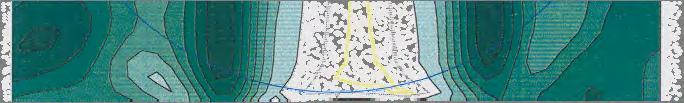


196 Figure 11.1 Iso-cylindrical contour plot for PAL 1. Figure 11.2 Iso-cylindrical contour plot for PAL 2 196


197 Figure 11.3 Iso-cylindrical contour plot for PAL PAL design differences Back vertex power of the PALs used in the experimental trials outlined in the previous sections was measured at three locations on the PAL, corresponding to the points on the lens surface through which the motion threshold target would be imaged. One location corresponded to the distance viewing portion of the PAL; back vertex power was taken as the power measured through the distance power circle of the PAL, and corresponds to the distance subjective refraction of the subject. Back vertex power was also measured at two peripheral points on the PAL. Position of these points on the PAL surface was calculated assuming a spectacle plane to centre of ocular rotation distance of 27mm, and referenced to the fitting cross position of the PAL, as this was fitted to pupil centre. Targets for measurement of peripheral minimum displacement thresholds were positioned 30º temporal to the visual axis; assuming a spectacle plane to centre of rotation distance of 27mm, this represents an area 15.6mm temporal to the fitting cross of the PAL in the spectacle plane (Figure 11.2). 197
Fundamentals of Progressive Lens Design
 Fundamentals of Progressive Lens Design VisionCare Product News Volume 6, Number 9 September 2006 By Darryl Meister, ABOM Progressive Lens Surfaces A progressive addition lens (or PAL ) is a type of multifocal
Varilux Comfort. Technology. 2. Development concept for a new lens generation
 Dipl.-Phys. Werner Köppen, Charenton/France 2. Development concept for a new lens generation In depth analysis and research does however show that there is still noticeable potential for developing progresive
UNITY VIA PROGRESSIVE LENSES TECHNICAL WHITE PAPER
 UNITY VIA PROGRESSIVE LENSES TECHNICAL WHITE PAPER UNITY VIA PROGRESSIVE LENSES TECHNICAL WHITE PAPER CONTENTS Introduction...3 Unity Via...5 Unity Via Plus, Unity Via Mobile, and Unity Via Wrap...5 Unity
3/31/2016. Presented by: Bob Alexander, ABOM/NCLE-AC Lens Consultant Vision Ease. Everywhere and Sportwrap; Understanding Digital Technology
 Everywhere and Sportwrap; Understanding Digital Technology Presented by: Bob Alexander, ABOM/NCLE-AC Lens Consultant Vision Ease Digital - Design and Surfacing VE Digital Designs Optimization Compensation
PREMIUM LENSES WITH VARIABLE BASE CURVE
 PREMIUM LENSES WITH VARIABLE BASE CURVE Inspired by nature - 1 - CONTENT THE ADVANCEMENT OF CAMBER CAMBER TECHNOLOGY Features and Properties Camber Benefits EXPLORING CAMBER LENS SERIES NATURAL NATURAL
OPHTHALMIC MATERIALS
 Matriculation Number: DEPARTMENT OF VISION SCIENCES SESSION: 2005/2006 DIET: 1ST OPHTHALMIC MATERIALS VISP209 LEVEL 2 MODULE LEADER: DR G WALSH B.Sc./B.Sc. (HONS) OPTOMETRY JANUARY 2006 DURATION: 2HOURS
Optical Perspective of Polycarbonate Material
 Optical Perspective of Polycarbonate Material JP Wei, Ph. D. November 2011 Introduction Among the materials developed for eyeglasses, polycarbonate is one that has a number of very unique properties and
The people-based design
 The people-based design InnoVision HOYA Vision Care Company always strives to develop new calculation techniques and optimisation methods that leads to the development of smarter lens designs. To enhance
A Checklist for Managing Spectacle Lens Complaints. Presented By: Raymond P. Dennis, M.A. (Ed.) Middlesex Community. Patient Complaints
 Middlesex Community. Patient Complaints") SPEAKER FINANCIAL DISCLOSURE STATEMENT Raymond P. Dennis has occasionally received honoraria from Essilor of America to present generic continuing education presentations similar to this one. He is a member
SPEAKER FINANCIAL DISCLOSURE STATEMENT Raymond P. Dennis has occasionally received honoraria from Essilor of America to present generic continuing education presentations similar to this one. He is a member
Chapter 3: LENS FORM Sphere
 Chapter 3: LENS FORM Sphere It can be helpful to think of very basic lens forms in terms of prisms. Recall, as light passes through a prism it is refracted toward the prism base. Minus lenses therefore
Agenda. 1. EyeLT Step 1 2. EyeLT Step 2 3. EyeLT Step 3
 EyeLT STEP 1-3 Agenda 1. EyeLT Step 1 2. EyeLT Step 2 3. EyeLT Step 3 Rodenstock unique selling propositions. EyeLT Step 1 EyeLT Step 2 EyeLT Step 3 + + Superior, clear vision from far to near. Up to 25%
SEIKO Superior. Most Advanced & Precisely Customized, 100% Internal Free-Form Technology
 SEIKO Superior Most Advanced & Precisely Customized, 100% Internal Free-Form Technology SEIKO Superior Precisely Customized Vision Advanced Optimized Performance for All Wearers The remarkably precise
CERTIFICATE IN DISPENSING OPTICS (CDO) Term-End Examination June, 2015
 Term-End Examination June, 2015") No. of Printed Pages : 8 OAH-005 CERTIFICATE IN DISPENSING OPTICS (CDO) Term-End Examination June, 2015 OAH-005 : PROGRESSIVE LENS Time : 90 Minutes Maximum Marks : 30 Note : (i) (ii) (iii) (iv) There
No. of Printed Pages : 8 OAH-005 CERTIFICATE IN DISPENSING OPTICS (CDO) Term-End Examination June, 2015 OAH-005 : PROGRESSIVE LENS Time : 90 Minutes Maximum Marks : 30 Note : (i) (ii) (iii) (iv) There
2008 Hoya Grant & Scholarship Wining Case Study
 2008 Hoya Grant & Scholarship Wining Case Study Progressive Lens Technology and the Implications for Struggling Presbyopes with Peripheral Distortion and Blur: A Case Study Andrew M. Graves 3 rd Year Optometry
Performance Factors. Technical Assistance. Fundamental Optics
 Performance Factors After paraxial formulas have been used to select values for component focal length(s) and diameter(s), the final step is to select actual lenses. As in any engineering problem, this
Fax: (800) Phone: (800) Fax: (800)
 Phone: (800) Fax: (800)") Fax: (800)628-9819 Phone: (800)525-1274 Fax: (800)628-9819 www.laramyk.com Calculation Technologies Laramy-k is proud to offer the most flexible solution with the possibility to access all the different
Fax: (800)628-9819 Phone: (800)525-1274 Fax: (800)628-9819 www.laramyk.com Calculation Technologies Laramy-k is proud to offer the most flexible solution with the possibility to access all the different
Copyright Indizen Optical Technologies
 DEFINITION OF FREEFORM Free form is a manufacturing technology that allows cutting and polishing arbitrary surfaces A lens is free-form if at least one of its surfaces is made with free form technology
DEFECTS OF VISION THROUGH APHAKIC SPECTACLE LENSES*t
 Brit. J. Ophthal. (1967) 51, 306 DEFECTS OF VISION THROUGH APHAKIC SPECTACLE LENSES*t BY ROBERT C. WELSH Miami, Florida BY the use of a series of scale diagrams an attempt is made to explain the following:
Multifocal Contact Lenses. Steps for Success. Disclosures. Patient Selection. Presbyopic Soft Contact Lenses: Options for Success
 Disclosures Outside Consultant Presbyopic Soft Contact Lenses: Options for Success Precilens Coopervision Research Funds Bausch and Lomb Brooke Messer, OD, FAAO, FSLS Cornea and Contact Lens Institute
Chapter 3. Adaptation to disparity but not to perceived depth
 Chapter 3 Adaptation to disparity but not to perceived depth The purpose of the present study was to investigate whether adaptation can occur to disparity per se. The adapting stimuli were large random-dot
VARILUX FITTING GUIDE GUIDELINES FOR SUCCESSFULLY FITTING VARILUX LENSES
 VARILUX FITTING GUIDE GUIDELINES FOR SUCCESSFULLY FITTING VARILUX LENSES WELCOME We are pleased to present this guide which outlines the essential steps for successfully fitting progressive lenses to your
KODAK Unique DRO Progressive Lens BE UNIQUE IN YOUR MODERN WORLD
 KODAK Unique DRO Progressive Lens BE UNIQUE IN YOUR MODERN WORLD NEW TECHNOLOGY UP CLOSE AND CLEAR Receive a fully-reinforced, reading area. KODAK Unique DRO Lens delivers a new level of near viewing with
VARILUX S SERIES COMPENDIUM. To learn more visit VariluxUSA.com
 To learn more visit VariluxUSA.com VARILUX S SERIES COMPENDIUM The Varilux S Series : Nanoptix Technology A Revolutionary Approach to Fundamental Progressive Lens Structure VARILUX S SERIES COMPENDIUM
Astigmatism. image. object
 TORIC LENSES Astigmatism In astigmatism, different meridians of the eye have different refractive errors. This results in horizontal and vertical lines being focused different distances from the retina.
EXAMINATION OF THE CENTRAL VISUAL FIELD AT
 Brit. J. Ophthal. (1968) 52, 408 EXAMINATION OF THE CENTRAL VISUAL FIELD AT A READING DISTANCE*t BY V. N. HIGHMAN Moorfields Eye Hospital, City Road, London THIS investigation was started in an attempt
C L I N I C A L A N D E X P E R I M E N T A L OPTOMETRY COMMENTARY. Understanding how simple magnifiers provide image enlargement
 C L I N I C A L A N D E X P E R I M E N T A L OPTOMETRY Simple magnifiers Johnston COMMENTARY Understanding how simple magnifiers provide image enlargement Clin Exp Optom 2003; 86: 6: 403 408 Alan W Johnston
AO TECHNICAL REPORT A STUDY OF LENS CONSTRUCTION AND USE AMERICAN OPTICAL CORPORATION SOUTHBRIDGE, MASSACHUSETTS 01550
 AO TECHNICAL REPORT A STUDY OF LENS CONSTRUCTION AND USE AMERICAN OPTICAL CORPORATION SOUTHBRIDGE, MASSACHUSETTS 01550 1 A STUDY OF LENS CONSTRUCTION AND USE JOHN K. DAVIS WHY A CHAPTER ON LENSES? The
SPHERE, CYLINDER, AXIS, and ADD Power: Why these four variables? Example Prescriptions: UNDERSTANDING A PRESCRIPTION SPHERICAL LENSES 8/31/2018
 8/31/2018 UNDERSTANDING A PRESCRIPTION Speaker: Michael Patrick Coleman, COT & ABOC SPHERE, CYLINDER, AXIS, and ADD Power: Why these four variables? Example Prescriptions: +2.50 SPH Simple SPHERICAL Rx
Soft CL Multifocals Design and Fitting. Soft Multifocal Lens Designs. Issues Surrounding Multifocals. Blur Interpretation. Simultaneous Vision Designs
 Soft CL Multifocals Design and Fitting Mark Andre, FAAO Associate Professor of Optometry Pacific University Mark Andre, FAAO is affiliated with CooperVision, as a consultant. Issues Surrounding Multifocals
10/25/2017. Financial Disclosures. Do your patients complain of? Are you frustrated by remake after remake? What is wavefront error (WFE)?
?") Wavefront-Guided Optics in Clinic: Financial Disclosures The New Frontier November 4, 2017 Matthew J. Kauffman, OD, FAAO, FSLS STAPLE Program Soft Toric and Presbyopic Lens Education Gas Permeable Lens
Wavefront-Guided Optics in Clinic: Financial Disclosures The New Frontier November 4, 2017 Matthew J. Kauffman, OD, FAAO, FSLS STAPLE Program Soft Toric and Presbyopic Lens Education Gas Permeable Lens
Learn Connect Succeed. JCAHPO Regional Meetings 2017
 Learn Connect Succeed JCAHPO Regional Meetings 2017 Refractometry JCAHPO Continuing Education Program Phoenix and Scottsdale, AZ Craig Simms BSc, COMT, CDOS, ROUB Director of Education, IJCAHPO Program
Fitting Manual Use with kerasofttraining.com
 Fitting Manual Use with Fitting Manual: Contents This fitting manual is best used in conjunction with KeraSoft IC online training. To register, please visit www. 01 Kerasoft IC Design - Outlines the KeraSoft
Progress in the spectacle correction of presbyopia. Part 1: Design and development of progressive lenses
 Clinical and Experimental Optometry: Authors Version of the Work Progress in the spectacle correction of presbyopia. Part 1: Design and development of progressive lenses Darryl J Meister ABOM Scott W Fisher
PROVISIONAL PATENT FOR MEASURING VISUAL CYLINDER USING A TWO-DIMENSIONAL SURFACE ABSTRACT OF THE DISCLOSURE:
 PROVISIONAL PATENT FOR MEASURING VISUAL CYLINDER USING A TWO-DIMENSIONAL SURFACE Inventors: Reid Laurens, Allan Hytowitz, Alpharetta, GA (US) 5 ABSTRACT OF THE DISCLOSURE: Visual images on a display surface
TORIC AND MULTIFOCAL GP AND SCL PRESCRIBING Edward S. Bennett OD, MSEd, FAAO
 1 2 3 4 5 6 1 TORIC AND MULTIFOCAL GP AND SCL PRESCRIBING Edward S. Bennett OD, MSEd, FAAO l Dr. Bennett is a consultant to the Contact Lens Manufacturers Association SOFT TORICS: Good Candidates l Astigmatic
OPTICS BASIC. Course Objectives WELCOME!!! Refractive Error and How Spectacle Lenses Correct It. Basic Anatomy. Hyperopia - Far Sighted PTICS:
 WELCOME!!! Course Objectives BASIC OPTICS PTICS: Refractive Error and How Spectacle Lenses Correct It Developed by: Susan I. Klacik, ABOC To review the basic elements of refractive error, and demonstrate
PART 3: LENS FORM AND ANALYSIS PRACTICE TEST
 PART 3: LENS FORM AND ANALYSIS PRACTICE TEST 1. 2. To determine the power of a thin lens in air, it is necessary to consider: a. front curve and index of refraction b. back curve and index of refraction
Lens Types. Single Vision. Lined Bi-Focal. Lined tri-focals
 Lenses It can be helpful to think of very basic lens forms in terms of prisms. As light passes through a prism it is refracted toward the prism base. Minus lenses therefore resemble two prisms apex to
FITTING GUIDE. Duette Hybrid Contact Lenses Duette Progressive Hybrid Contact Lenses - Center Distance - Center Near
 FITTING GUIDE Duette Hybrid Contact Lenses Duette Progressive Hybrid Contact Lenses - Center Distance - Center Near P R O G R E S S I V E The unique advanced-technology Duette hybrid contact lenses are
Heads you win, tails you lose
 4 dispensingoptics September 2014 Heads you win, tails you lose By Andrew Keirl BOptom (Hons) MCOptom FBDO CompetencIes covered: Dispensing opticians: Ocular Examination, Contact Lenses, efractive Management
What s a Corneal GP Lens?
 Slide 1 What s a Corneal GP Lens? Richard Dorer NCLEC Blanchard Contact Lens Inc. 800-367-4009 x 131 richarddorer@gmail.com www.blanchardlab.com Slide 2 Endorsements I am a paid representative and consultant
Eschenbach Low Vision Training Program
 Eschenbach Low Vision Training Program Module 5: Magnifying Spectacles Edited by: Thomas Porter, OD Asst. Professor & Director Low Vision Service St. Louis University, Dept. of Ophthalmology 2016 2015
Irregular Cornea. ROSE K2 Soft TM. Practitioner s Fitting Guide
 Irregular Cornea ROSE K2 Soft TM Practitioner s Fitting Guide ROSE K2 Soft Applications Design ROSE K2 Soft is a daily wear soft lens for irregular corneas. ROSE K2 Soft is a 3 month replacement lens when
The optics of occupational progressive lenses
 The optics of occupational progressive lenses James E. Sheedy, O.D., Ph.D. and Raymond F. Hardy, B.S. The Ohio State University College of Optometry, Columbus, Ohio Background: Occupational progressive
GEOMETRICAL OPTICS AND OPTICAL DESIGN
 GEOMETRICAL OPTICS AND OPTICAL DESIGN Pantazis Mouroulis Associate Professor Center for Imaging Science Rochester Institute of Technology John Macdonald Senior Lecturer Physics Department University of
The soft approach to RGPs
 CET CONTINUING EDUCATION & TRAINING Sponsored by 1 CET POINT The soft approach to RGPs Part 3: don t let torics put you in a spin 46 Mark Tomlinson BSc (Hons), MCOptom, FBDO (Hons) Most practitioners acknowledge
Chapter 6. Experiment 3. Motion sickness and vection with normal and blurred optokinetic stimuli
 Chapter 6. Experiment 3. Motion sickness and vection with normal and blurred optokinetic stimuli 6.1 Introduction Chapters 4 and 5 have shown that motion sickness and vection can be manipulated separately
Refraction Training Manual
 INTERNATIONAL CENTRE FOR EYE HEALTH Refraction Training Manual 2006 Mr S. Mayer & International Centre for Eye Health Contents Page 1. Introduction 2. Basic Optics 3. Vision and Visual Acuity 4. Refractive
Patient information. Your options for cataract treatment Enjoy clear vision at all distances with multifocal IOLs
 Patient information Your options for cataract treatment Enjoy clear vision at all distances with multifocal IOLs Bring your vision into focus Good vision is a major contributor to the quality of life.
Concepts of Optics Quiz. 8. Spherical lenses focus along a single point; cylindrical lenses focus along a.
 Concepts of Optics Quiz 1. Prisms bend light from (apex/base) to (apex/base). 2. Prisms displace images in the direction of the (apex/base). 3. A (plus/minus) lens is convex. 4. A (plus/minus) lens diverges
Vision Science I Exam 2 31 October 2016
 Vision Science I Exam 2 31 October 2016 1) Mr. Jack O Lantern, pictured here, had an unfortunate accident that has caused brain damage, resulting in unequal pupil sizes. Specifically, the right eye is
Contact Lenses Didn t Work! Now What? Evaluation and Treatment of Aniseikonia
 Contact Lenses Didn t Work! Now What? Evaluation and Treatment of Aniseikonia Andrew J Toole, OD, PhD, FAAO The Ohio State University College of Optometry Disclosure Statement: Nothing to disclose Aniseikonia
Multiple-Choice Questions
 Multiple-Choice Questions A Board Review Manual 1. A +5.ooD hyperope, with a PD (inter-pupillary distance) of 5 centimeters, is mistakenly given glasses which are decentered outward by 5mm OU. The total
MULTIFOCAL CONTACT LENSES INTRODUCTION
 Mario Giovanzana Milano, 15 th december 00 MULTIFOCAL CONTACT LENSES INTRODUCTION In my professional experience over the years I ve developed both support in the production of contact lense as well their
Chapter 9 - Ray Optics and Optical Instruments. The image distance can be obtained using the mirror formula:
 Question 9.1: A small candle, 2.5 cm in size is placed at 27 cm in front of a concave mirror of radius of curvature 36 cm. At what distance from the mirror should a screen be placed in order to obtain
PART 3: LENS FORM AND ANALYSIS PRACTICE TEST - KEY
 PART 3: LENS FORM AND ANALYSIS PRACTICE TEST - KEY d 1. c 2. To determine the power of a thin lens in air, it is necessary to consider: a. front curve and index of refraction b. back curve and index of
ORLAB Technical Note
 ORLAB Technical Note Ophthalmic Product Series Issue 6 A series of technical notes to aid understanding of standards, reasons for failure to comply and hints on avoiding the problem. Differences between
continuing education course Approved by the American Board of Opticianry
 continuing education course Approved by the American Board of Opticianry Average Math for the Above Average Dispenser National Academy of Opticianry 8401 Corporate Drive #605 Landover, MD 20785 800-229-4828
digital lens designs
 digital lens designs Lens Calculation Technology Lens Design Software Technology Evolution Camber Digital Ray-Path Surface Power Calculation Technologies Lens Design Portfolio IOT Lens Design Portfolio
Ophthalmic optics Mounted spectacle lenses
 Provläsningsexemplar / Preview INTERNATIONAL STANDARD ISO 21987 Second edition 2017-07 Ophthalmic optics Mounted spectacle lenses Optique ophtalmique Verres ophtalmiques montés Reference number ISO 2017
This is the author s version of a work that was submitted/accepted for publication in the following source:
 This is the author s version of a work that was submitted/accepted for publication in the following source: Atchison, David A. & Mathur, Ankit (2014) Effects of pupil center shift on ocular aberrations.
The Persistence of Vision in Spatio-Temporal Illusory Contours formed by Dynamically-Changing LED Arrays
 The Persistence of Vision in Spatio-Temporal Illusory Contours formed by Dynamically-Changing LED Arrays Damian Gordon * and David Vernon Department of Computer Science Maynooth College Ireland ABSTRACT
Corneal Asphericity and Retinal Image Quality: A Case Study and Simulations
 Corneal Asphericity and Retinal Image Quality: A Case Study and Simulations Seema Somani PhD, Ashley Tuan OD, PhD, and Dimitri Chernyak PhD VISX Incorporated, 3400 Central Express Way, Santa Clara, CA
Special Publication: Ophthalmochirurgie Supplement 2/2009 (Original printed issue available in the German language)
") Special Publication: Ophthalmochirurgie Supplement 2/2009 (Original printed issue available in the German language) LENTIS Mplus - The one -and and-only Non--rotationally Symmetric Multifocal Lens Multi-center
Special Publication: Ophthalmochirurgie Supplement 2/2009 (Original printed issue available in the German language) LENTIS Mplus - The one -and and-only Non--rotationally Symmetric Multifocal Lens Multi-center
With the prevalence of
 Complete course in dispensing Part 6 Lens selection After last month s article (November 14, 2008) discussing the basic properties of materials used for the manufacture of spectacle lenses, Andrew Keirl
Role of Mandelbaum-like effect in the differentiation of hyperopes and myopes using a hologram
 Role of Mandelbaum-like effect in the differentiation of hyperopes and myopes using a hologram Nicholas Nguyen Chitralekha S. Avudainayagam Kodikullam V. Avudainayagam Journal of Biomedical Optics 18(8),
Custom Solutions Catalog Prescription Corrected Solutions For Your Most Challenging Patients
 Custom Solutions Catalog Prescription Corrected Solutions For Your Most Challenging Patients Prescription Corrected Eyewear Page 2 Prescription Corrected Filters Page 4 Eschenbach Telescope Mounting Page
Aspects of Vision. Senses
 Lab is modified from Meehan (1998) and a Science Kit lab 66688 50. Vision is the act of seeing; vision involves the transmission of the physical properties of an object from an object, through the eye,
Spatial Judgments from Different Vantage Points: A Different Perspective
 Spatial Judgments from Different Vantage Points: A Different Perspective Erik Prytz, Mark Scerbo and Kennedy Rebecca The self-archived postprint version of this journal article is available at Linköping
Camera Resolution and Distortion: Advanced Edge Fitting
 28, Society for Imaging Science and Technology Camera Resolution and Distortion: Advanced Edge Fitting Peter D. Burns; Burns Digital Imaging and Don Williams; Image Science Associates Abstract A frequently
Psych 333, Winter 2008, Instructor Boynton, Exam 1
 Name: Class: Date: Psych 333, Winter 2008, Instructor Boynton, Exam 1 Multiple Choice There are 35 multiple choice questions worth one point each. Identify the letter of the choice that best completes
ISO INTERNATIONAL STANDARD. Ophthalmic optics Mounted spectacle lenses. Optique ophtalmique Verres ophtalmiques montés. First edition
 Provläsningsexemplar / Preview INTERNATIONAL STANDARD ISO 21987 First edition 2009-10-01 Ophthalmic optics Mounted spectacle lenses Optique ophtalmique Verres ophtalmiques montés Reference number ISO 21987:2009(E)
Spectacle lens design following Hamilton, Maxwell and Keller
 Spectacle lens design following Hamilton, Maxwell and Keller Koby Rubinstein Technion Koby Rubinstein (Technion) Spectacle lens design following Hamilton, Maxwell and Keller 1 / 23 Background Spectacle
HARD TORIC CONTACT LENSES ASTIGMATISM DEFINITION AND OPTIC BASIS
 Mario Giovanzana Milano 20.06.01 HARD TORIC CONTACT LENSES ASTIGMATISM DEFINITION AND OPTIC BASIS An astigmatism, according to Whevell (1817) has been defined as astigmatism or astigmatic ametropia; the
Downloaded from
 QUESTION BANK SCIENCE STD-X PHYSICS REFLECTION & REFRACTION OF LIGHT (REVISION QUESTIONS) VERY SHORT ANSWER TYPE (1 MARK) 1. Out of red and blue lights, for which is the refractive index of glass greater?
FITTING GUIDE PRACTITIONER S ROSE K2 KC ROSE K2 NC ROSE K2 IC ROSE K2 PG NIPPLE CONE IRREGULAR CORNEA POST GRAFT
 Keratoconus Nipple Cone Irregular Cornea Post Graft PRACTITIONER S FITTING GUIDE NIPPLE CONE IRREGULAR CORNEA POST GRAFT Four lens designs... One simple systematic approach to fitting Featuring Easy-to-fit
OPTICAL SYSTEMS OBJECTIVES
 101 L7 OPTICAL SYSTEMS OBJECTIVES Aims Your aim here should be to acquire a working knowledge of the basic components of optical systems and understand their purpose, function and limitations in terms
AUNIQUE B REAKTHROUGH I N P ROGRESSIVE L ENS T ECHNOLOGY
 ELA016 VxIpeso ECP Brochure.qxd 4/10/06 11:24 AM Page 1 AUNIQUE B REAKTHROUGH I N P ROGRESSIVE L ENS T ECHNOLOGY Integrates point by point the movements of your eyes. INTRODUCING VARILUX IPSEO The first
Waves & Oscillations
 Physics 42200 Waves & Oscillations Lecture 33 Geometric Optics Spring 2013 Semester Matthew Jones Aberrations We have continued to make approximations: Paraxial rays Spherical lenses Index of refraction
Wave Front Topography. ReSeeVit Evolution Topography Module for Modi Topographer
 Wave Front Topography ReSeeVit Evolution Topography Module for Modi Topographer Introduction The aberrations in the central optical zone have a greater effect than those closer to the edge. From an optical
STUDY OF ADULT STRABISMUS TESTING PROCEDURES MANUAL
 STUDY OF ADULT STRABISMUS TESTING PROCEDURES MANUAL Version 3.0 July 13, 2016 SAS1 s Manual_v3.0_7-13-16 1 CONVERGENCE INSUFFICIENCY SYMPTOM SURVEY (CISS)... 3 Convergence Insufficiency Symptom Survey
Wavefront-Guided Programmable Spectacles Related Metrics
 Wavefront-Guided Programmable Spectacles Related Metrics Lawrence Sverdrup, Sean Sigarlaki, Jeffrey Chomyn, Jagdish Jethmalani, Andreas Dreher Ophthonix, Inc. 23rd February 2007 Outline Background on Ophthonix
MOTION PARALLAX AND ABSOLUTE DISTANCE. Steven H. Ferris NAVAL SUBMARINE MEDICAL RESEARCH LABORATORY NAVAL SUBMARINE MEDICAL CENTER REPORT NUMBER 673
 MOTION PARALLAX AND ABSOLUTE DISTANCE by Steven H. Ferris NAVAL SUBMARINE MEDICAL RESEARCH LABORATORY NAVAL SUBMARINE MEDICAL CENTER REPORT NUMBER 673 Bureau of Medicine and Surgery, Navy Department Research
Appendix III Graphs in the Introductory Physics Laboratory
 Appendix III Graphs in the Introductory Physics Laboratory 1. Introduction One of the purposes of the introductory physics laboratory is to train the student in the presentation and analysis of experimental
CHAPTER 33 ABERRATION CURVES IN LENS DESIGN
 CHAPTER 33 ABERRATION CURVES IN LENS DESIGN Donald C. O Shea Georgia Institute of Technology Center for Optical Science and Engineering and School of Physics Atlanta, Georgia Michael E. Harrigan Eastman
AT LISA tri 839MP and AT LISA tri toric 939MP from ZEISS The innovative trifocal IOL concept providing True Living Vision to more patients
 Premium Trifocal MICS OVDs IOLs AT LISA tri 839MP and AT LISA tri toric 939MP from ZEISS The innovative trifocal IOL concept providing True Living Vision to more patients The moment you help your patients
(12) Patent Application Publication (10) Pub. No.: US 2007/ A1
 Patent Application Publication (10) Pub. No.: US 2007/ A1") US 200700.973 18A1 (19) United States (12) Patent Application Publication (10) Pub. No.: US 2007/0097318A1 Chehab et al. (43) Pub. Date: (54) OPHTHALMIC LENSES USEFUL FOR THE Related U.S. Application Data
US 200700.973 18A1 (19) United States (12) Patent Application Publication (10) Pub. No.: US 2007/0097318A1 Chehab et al. (43) Pub. Date: (54) OPHTHALMIC LENSES USEFUL FOR THE Related U.S. Application Data
OPTICAL DEMONSTRATIONS ENTOPTIC PHENOMENA, VISION AND EYE ANATOMY
 OPTICAL DEMONSTRATIONS ENTOPTIC PHENOMENA, VISION AND EYE ANATOMY The pupil as a first line of defence against excessive light. DEMONSTRATION 1. PUPIL SHAPE; SIZE CHANGE Make a triangular shape with the
PERIMETRY A STANDARD TEST IN OPHTHALMOLOGY
 7 CHAPTER 2 WHAT IS PERIMETRY? INTRODUCTION PERIMETRY A STANDARD TEST IN OPHTHALMOLOGY Perimetry is a standard method used in ophthalmol- It provides a measure of the patient s visual function - performed
ORIGINAL ARTICLE. The Proximity-Fixation-Disparity Curve and the Preferred Viewing Distance at a Visual Display as an Indicator of Near Vision Fatigue
 1040-5488/02/7903-0158/0 VOL. 79, NO. 3, PP. 158 169 OPTOMETRY AND VISION SCIENCE Copyright 2002 American Academy of Optometry ORIGINAL ARTICLE The Proximity-Fixation-Disparity Curve and the Preferred
Automated Perimeter PTS 1000
 PTS 1000 Automated Perimeter PTS 1000 is a modern diagnostic instrument for precise and fast testing of field of vision. It offers static and kinetic stimuli with all Goldmann stimuli sizes and all stimuli
Treatment of Presbyopia during Crystalline Lens Surgery A Review
 Treatment of Presbyopia during Crystalline Lens Surgery A Review Pierre Bouchut Bordeaux Ophthalmic surgeons should treat presbyopia during crystalline lens surgery. Thanks to the quality and advancements
EYE-REFRACTIVE ERRORS
 VISUAL OPTICS LABORATORY EYE-REFRACTIVE ERRORS Prof.Dr.A.Necmeddin YAZICI GAZİANTEP UNIVERSITY OPTİCAL and ACOUSTICAL ENGINEERING DEPARTMENT http://opac.gantep.edu.tr/index.php/tr/ 1 2 REDUCED EYE The
Perceiving binocular depth with reference to a common surface
 Perception, 2000, volume 29, pages 1313 ^ 1334 DOI:10.1068/p3113 Perceiving binocular depth with reference to a common surface Zijiang J He Department of Psychological and Brain Sciences, University of
HOYA TECHNOLOGY REFERENCE GUIDE
 HOYA TECHNOLOGY REFERENCE GUIDE Over 50 years of optical engineering www.thehoyafreeformcompany.com REDEFINING EVERY ASPECT OF VISION CORRECTION > Progressive lenses were first patented
hoya technology reference guide
 hoya technology reference guide Over 50 years of optical engineering www.thehoyafreeformcompany.com redefining every aspect of vision correction > Lens Series Progressive lenses were
Professional Fitting and Information Guide
 Professional Fitting and Information Guide FOCUS DAILIES FOCUS DAILIES Toric FOCUS DAILIES Progressives DAILIES AquaComfort Plus DAILIES AquaComfort Plus Toric DAILIES AquaComfort Plus Multifocal (nelfilcon
THE EFFECT OF MODIFIED SPECTACLES ON THE FIELD OF VIEW OF THE HELMET DISPLAY UNIT OF THE INTEGRATED HELMET AND DISPLAY SIGHTING SYSTEM
 USAARL REPORT NO. 84-12 THE EFFECT OF MODIFIED SPECTACLES ON THE FIELD OF VIEW OF THE HELMET DISPLAY UNIT OF THE INTEGRATED HELMET AND DISPLAY SIGHTING SYSTEM By William E. McLean Clarence E. Rash SENSORY
Peripheral Prism Glasses for Hemianopia Giorgi et al. APPENDIX 1
 1 Peripheral Prism Glasses for Hemianopia Giorgi et al. APPENDIX 1 Monocular and binocular sector prisms are commonly used for hemianopia.3, 10, 14 The impact of these prisms on the visual field is not
NEW. AT LISA tri 839MP and AT LISA tri toric 939MP from ZEISS The innovative trifocal IOL concept providing True Living Vision to more patients
 Premium Trifocal MICS OVDs IOLs NEW AT LISA tri 839MP and AT LISA tri toric 939MP from ZEISS The innovative trifocal IOL concept providing True Living Vision to more patients Trifocal toric IOL The moment