IMPORTANT SAFETY INSTRUCTIONS
|
|
|
- Amie Pierce
- 5 years ago
- Views:
Transcription
1
2
3 Version 2.0 Table of contents IMPORTANT SAFETY INSTRUCTIONS 2 EMC/EMI & CERTIFICATE OF CONFORMITY 2 PACKAGE CONTENT 3 STRUCTURE 4 SIGNAL S PATH DIAGRAM 5 BANKS, PRESETS AND MODIFIERS 6 PRESET SELECTION 6 BANK SELECTION 6 SILENT TUNING (MUTE) 7 PRESET PROGRAMMING 7 LOOPS (LOOP1 TO LOOP6) PROGRAMMING 7 AMP SETTINGS PROGRAMMING 7 MIDI PROGRAM NUMBERS PROGRAMMING 8 PRESET S COPYING 8 BANK COPYING 8 CC CONTROLLERS VALUE PROGRAMMING 8 SENDING ADDITIONAL PROGRAM CHANGE COMMANDS 9 MODIFIERS PROGRAMMING 9 TAP TEMPO 10 SETTINGS 10 LOOP BUTTON SETTINGS 10 SWITCH BUTTON SETTINGS 11 MIDI CHANNELS SETTING 12 AMP S CONTROL CONNECTING 12 G LAB WP WAH-PAD CONNECTING 12 G LAB TBWP TRUE BYPASS WAH-PAD CONNECTING 13 CONNECTING AUX BANK UP/DOWN WITH MIDI IN FOOTSWITCH 13 USB CONNECTING WITH PC 13 AUX CONNECTOR 13 MIDI 2 X LOOP CONNECTING 13 TECHNICAL PARAMETERS 14 MIDI IMPLEMENTATION CHART 15 1
4 Important safety instructions Read these instructions and follow them. Prevent this device against moisture or spilling liquid inside. Clean only with dry cloth. Do not install near any heat sources such as radiators, heat registers, stoves, or other apparatus producing a lot of heat Protect the power supply cord from being walked on or pinched. Only use attachments/accessories specified by the manufacturer. Unplug this device during lighting storms or when unused for long periods of time. Do no open device or its power supply casing. The power supply adapter should be installed in the socket outlet and disconnection of the adapter should be easily accessible. To completely disconnect from AC mains disconnect the power supply adapter from the AC receptacle. EMC/EMI & Certificate of conformity EMC/EMI This device has been designed and manufactured to conform with directives and standards in the field of safety operations and electromagnetic interference. This device uses and can radiate radio frequency energy and, if not installed and used in accordance with the instructions, may cause harmful interference to radio communications. However in spite of performing below standards there is no guarantee that interference will not occur in a particular installation. If this device does cause harmful interference to radio or television reception which can be determined by turning the device on and off, the user is encouraged to try to correct the interference by one or more of the following operations: Reorient or relocate the receiving antenna. Increase the separation between the device and receiver. Connect the device into an outlet on a circuit different from that to which the receiver is connected. Contact with the manufacturer (see: Before calling a service). Consult the dealer for help. Certificate of Conformity ELZAB S.A., ul. Kruczkowskiego 39, Zabrze, Poland, hereby declares on own responsibility that the following product: GSC-3, GSC-2 Guitar System Controller that is covered by this certificate and marked with CE 07 label conforms with following standards: PN-EN 60065:2004 Safety requirements for mains operated electronic and related apparatus for household and similar general use PN-EN :1998 Product family standard for audio, video, audio-visual and entertainment lighting control apparatus for professional use. Part 1: Emission. PN-EN :1998 Product family standard for audio, video, audio-visual and entertainment lighting control apparatus for professional use. Part 2: Immunity. With reference to regulations in following directives: 73/23/EEC, 2004/108/EEC Issued in Zabrze, March 2009 Jerzy Biernat President of the ELZAB S.A. Board of Directors 2
5 Dear Customer, Congratulations for choosing our G LAB product! Guitar System Controller (GSC) is the programmable switching device of effects loops (looper), the amp s switcher by footswitch input and the MIDI devices controller in one. By pressing just a single footswitch (called preset) it enables: to activate selected effects (connected to LOOP1 up to LOOP6 loops), to set the amp channel (or the pre-amp one) and other amp s functions controlled by its footswitch input, to set by Program Change command the MIDI device s program No. of work (at three MIDI devices e.g. effects processors). The presets are stored in 10 banks. Depending on the method of changing the banks there are available eight or ten presets in each bank. Controller posses presets programming function and presets and banks copying functions what enables quick organising of the presets in the banks. The GSC enables also to assign to its footswitches following functions instead of presets: to switch on/off the loop (loop modifier), to set the amp settings function (e.g. selecting a channel), to select the program No. (or numbers) of MIDI device (devices). To avoid the incidental changing of the presets settings the controller is equipped with the memory access lock. There are available two versions of the controller with different footswitches. The GSC-3 model posses metal footswitches with backligthed descriptions and the GSC-2 model posses silent, backlighted footswitches. Basic characteristics: true passive signal path (except buffer), true bypassed (by relay), high impedance input buffer, TUNER output with the silent tuning function based on very high impedance circuit (no influence on a guitar signal), six TRUE BYPASS loops for connecting effects (using electro-mechanical relays), six 9V DC outputs (for supplying effects) in two separated sections (500mA each), 2 outputs (2 lines each, latching type) for controlling the amp through its footswitch input, MIDI output for controlling MIDI devices by Program Change and Control Change commands, AUX connector for connecting extension modules, USB connector for connecting to a PC, enabling downloading, editing and saving presets and settings, also firmware upgrades, two modes of bank selection (by BANK UP / BANK DOWN footswitches or by pressing and holding presets footswitches) and an option one bank mode, input for connecting a wah-wah effect pad (wah-pad) to control the system by placing the foot on the wah-wah, external power supply with 4 meters long and flexible cable Package content Controller Power supply adapter Three 9V 40 cm cables Two 9V 80 cm cables One 9V 120 cm cables User s Manual 3

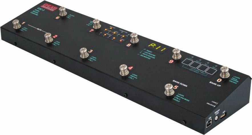
6 Structure On the inner side of the instruction cover are placed the pictures with elements numerated below. 1 - IN guitar signal input 2 - TUNER guitar tuner connector 3 - OUT amp s signal output connector 4 - SEND effect s loop output connector 5 - RETURN effect s loop input connector 6 - OUT SW1&2 and SW3&4 output connectors for amp's switching by its footswitch input 7 - WAH-PAD wah-pad connector 8 - MIDI OUT MID output connector 9 - POWER 12V DC 12V DC power supply connector 10 - OUT 9V DC Effects power supply connectors 11 - Presets selecting footswitches 12 - Indicators 13 - Display 14 - Programming buttons 15 - AUX connector 16 - Memory access lock switch 17 - USB connector BUFFER Buffer indicator LOOP 1 to 6 Indicators signalising switching on LOOPs POWER FAIL Voltage failure indicator (voltage below 11.2V or above 12,8V) SWITCH 1 to 4 SW1 to SW4 switch outputs status indicators LOCK Memory access LOCK indicator LOOP loops programming button and indicator SWITCH amp s controlling outputs button and indicator MIDI 1 button and indicator for editing MIDI program of MIDI 1 device MIDI 2 button and indicator for editing MIDI program of MIDI 2 device 4
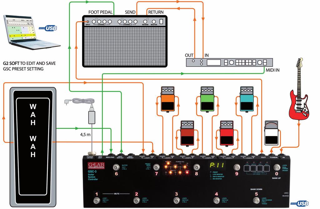
7 Signal s path diagram Guitar signal, thru very high impedance (>10 MΩ) tuner buffer, is transmitted to TUNER output. It enables using of the tuner during playing. Controller features a switchable, true bypass input buffer circuit. Buffer which s input impedance is consistent with tube amps boost the guitar signal power (without the voltage increase). Adding the buffor between the guitar and the effect can improve guitar sound (due to low input impedance many of the effects change the guitar tone) and in case of using long cables (between the controller and the amp) it enables to avoid high tones loss caused by cables parasitic capacitance appearing when all the effects are switched off. SEND outputs should be connected with IN effects inputs and RETURN inputs should be connected with OUT outputs of particular effects. MUTE block silents the signal during the quiet tunning. Controller has six 9V DC outputs for supplying the effects in two fully separated sections (500mA each). Before plugging the power supply the pin polarization coincidence should be checked. 5
8 Banks, presets and modifiers Controller enables to program 10 presets (or 8 ones) in each of its 10 banks. There is information on the display about the bank and preset numbers. Banks and presets have got numbers from 0 to 9 range. bank number 2 preset mode preset number 3 The P character in front of double dot says that the given footswitch in the given bank is a preset. The L character says that the given footswitch is a loop modifier (similarly S character for a SWITCH modifier and n character for a MIDI modifier). The loop modifier switches on and off the selected effects loop. The SWITCH modifier sets the amp s channel. The MIDI modifier sends the Program Change and/or Control Change MIDI commands to selected MIDI devices. Such solution enables to program banks only with presets to switch all the system just by pressing a single footswitch and to program the banks where particular footswitches perform the selected functions e.g. to switch on the single effect, to set the amps channel. Also it is possible to program some banks where a part of footswitches are presets and the other are modifiers. Below you will find the example of using presets and modifiers. Preset selection Press shortly (less then 1 second) the preset footswitch numbered from 1 to 5 (in the cb1 mode banks change from 0 to 9; in the cb2 mode banks change from 1 to 4 or from 6 to 9). Bank selection At the cb1 mode (pressing and holding preset footswitch). Press and hold (more then 1 second) the desired preset footswitch numbered from 0 to 9. During switching there will be activated for 1 second the preset adequate to the previously selected bank. Choosing this method enables to use 10 presets in each bank. It is recommended to organise presets in banks in such a way that all necessary presets used in a particular song will be located into just one bank. At the cb2 mode (using BANK UP / BANK DOWN buttons). Select the bank number using BANK UP (footswitch 0) or BANK DOWN (footswitch 5) and then press the preset footswitch (from range 1 to 4 or 6 to 9). Till the moment the preset footswitch is pressed the previous preset is active. It enables switching presets from the different banks while a song is played. Choosing this method enables to use 8 presets in each bank. 6
9 To escape from the bank selecting function press and hold 0 or 5 footswitch longer then 1 second. At the cb3 mode (directly by using BANK UP/BANK DOWN footswitches for firmware 2.20 and higher). At this mode BANK UP and BANK DOWN footswitches cause correspondingly lowering and increasing bank number with immediate preset recalling (preset number in bank remains unchanged). Silent tuning (MUTE) Press simultaneously the footswitch No. 1 and 2 (blinking tun text will appear on the display). To exit from MUTE press the preset footswitch intended to be used. Preset programming A preset is defined by: switched on effects (connected to LOOP1 to LOOP6) and buffer switched on or off; amp s setting (amp channel and/or effect selecting) controlled by SW1 to SW4 outputs; MIDI Program Change numbers (and Control Change commands) transmitted to MIDI devices. Loops (LOOP1 to LOOP6) programming a) Select bank and preset. b) Memory access lock switch to UNLOCK position (LOCK indicator not lit). c) Press LOOP button (LOOP indicator and preset number start to blink). d) Check if P character is displayed before the double dot. If not set it by footswitch No. 7 (PRESET MODE) e) By presets footswitches 1 to 5 and 0 set loops (effects) which should be active (indicators LOOP 1 to 6 lit mean effects are activated). Switch on/off the buffer by footswitch No. 6 (BUFFER indicator lit means the buffer is active). f) Press LOOP button to save. Displaying text Stored confirm saving. In case of necessity of escape without saving while the point d) or e) it should be pressed SWITCH or MIDI 1 or MIDI 2 button. REMARK: In case of not plugging in a connector to a particular effect s loop RETURN the signal will skip such a loop despite of activating this loop. It allows to use presets despite of not connecting effects to such a loop. Amp settings programming a) Select bank and preset. b) Memory access lock switch to UNLOCK position (LOCK indicator not lit). c) Press SWITCH button (SWITCH indicator and preset number start to blink). d) By footswitches 1 to 4 set SWITCH outputs (SW1 to SW4 indicators signalise amp settings). e) Press SWITCH button to save. Displaying text Stored confirm saving. In case of necessity of escape without saving while the point d) it should be pressed LOOP or MIDI 1 or MIDI 2 button. 7
10 MIDI program numbers programming The controller enables to control three MIDI devices (MIDI 1, MIDI 2 and MIDI 3) by the Program Change command. Before programming, the MIDI channels should be set (see: MIDI channel setting). a) Connect MIDI cable between MIDI OUT output connector and MIDI IN input connector of the controlled device. b) Select bank and preset. c) Memory access lock switch to UNLOCK position (LOCK indicator not lit). d) Press MIDI 1 button (MIDI 1 indicator will start to blink). Actual program No. or text unused (what means that command is not send) will appear on display. e) Enter program No. using footswitches (e.g. for program No. 24 press footswitch No. 2 and then footswitch No. 4). If you don t want to send Program Change command in this preset press footswitch No. 0 and hold for minimum 1 second (text unu will appear on display). Available program numbers are from 1 to 128 (transmitted values from 0 to 127). The text Err means the number is out of the range. f) Press MIDI 1 button to save. Displaying text Stored confirms saving. In case of necessity of escape without saving while the point e) it should be pressed LOOP or SWITCH button. For MIDI 2 device do it in similar way and for MIDI 3 device the MIDI 1 and MIDI 2 buttons should be pressed simultaneously. The MIDI 3 program number can be programmed in this way only when the setting at LOOP button (No. 6 footswitch) is set to n3p (MIDI 3, only Program Change command). Preset s copying a) Select preset to copy. b) Memory access lock switch to UNLOCK position (LOCK indicator not lit). c) Press at simultaneously LOOP and MIDI 2 buttons (LOOP and MIDI 2 indicators start to blink and SWITCH and MIDI 1 indicators start to lit). d) Switch bank (if necessary) and choose preset No. where to past copied preset. e) Press simultaneously LOOP and MIDI 2 buttons to save preset. Text Stored confirms saving. In case of necessity of escaping without saving while in the point d) should be pressed SWITCH or MIDI 1 button. Bank copying a) Select any preset of the bank to copy. b) Memory access lock switch to UNLOCK position (LOCK indicator not lit). c) Press simultaneously SWITCH and MIDI 1 buttons (SWITCH and MIDI 1 indicators start to blink and LOOP and MIDI 2 indicators start to lit). d) Choose a bank where to past copied bank. e) Press simultaneously SWITCH and MIDI 1 buttons to save bank. Text Stored confirms saving. In case of necessity of escaping without saving while in the point d) should be pressed LOOP or MIDI 2 button. CC controllers value programming The GSC enables to control MIDI 3 device by Control Change commands. Before value programming at LOOP button settings (footswitch No. 6) set transmitting Control Change commands (m3c), and set controllers numbers (see: Controllers numbers setting for Control Change commands). a) Select bank and preset. b) Memory access lock switch to UNLOCK position (LOCK indicator not lit). c) Press simultaneously MIDI 1 and MIDI 2 buttons (MIDI 1 and MIDI 2 indicators start to blink). The text ctl will appear on display. 8
11 d) Short pressing footswitches numbered from 1 to 7 will effect in short displaying text CC and the controllers No. e.g. 81 and after actual value of the controller will be displayed. Pressing No. 0 footswitch displays the actual program No. transmitted to the MIDI 3 device by Program Change command. e) Press and hold for longer than 1 second the controller footswitch intended to be changed (blinking 0 will appear on display). g) Enter the value of controller using footswitches. The controller value can be from 0 to 127 range, unused or toggle. Press and hold for longer than 1 second footswitch No. 0 to set the controller unused (not to be transmitted). To set the toggle function press and hold for longer than 1 second the footswitch No. 5. Toggle function means that successive pressing the footswitch toggles transmitted values 0 and 127 and effects in switching on/off a chosen parameter or a function of MIDI 3 device. In case when we programmed the footswitch as a MIDI modifier and the only transmitted command is toggle value controller we get the footswitch e.g. switching on and off a single effect at multieffect device. In this way we get the functionality of such a footswitch identical with loop modifier (for a single effect as stompbox connected to a loop). When at other preset or modifier the given controller is transmitted then toggle function will consider the previously transmitted value. g) Press MIDI 1 (or MIDI 2) button to accept the value. If you want to edit the value of other controller operate according to point d) and e). h) Press simultaneously MIDI 1 and MIDI 2 buttons to save entered vales. Text Stored confirms saving. In case of necessity of escaping without saving while in the point d) should be pressed LOOP or SWITCH button. Sending additional Program Change commands (for firmware 2.20 and higher) Controller enables sending out four additional Program Change commands (named PC4 to PC7) instead of Control Change 4 to 7 commands. To use this option it is needed: to set at LOOP button settings (footswitch No. 6) transmitting three Control Change and five Program Change (m3a) commands, to set at SWITCH button settings the channel numbers for MIDI 4 to MIDI 7 instead of the controller numbers CTRL 4 to CTRL 7, to enter the program numbers to send in place of the controller values CTRL4 do CTRL7. On display, in place of the CC and controller s number, will appear the PC with the number of MIDI device to which will be sent the program number. Modifiers programming Modifiers enable to program the controller in such a way that the given footswitch in the chosen bank instead of preset function would serve one of the following functions: switching on and off an effect connected to an effect loop (LOOP MODIFIER), setting the amp at a chosen channel (SWITCH MODIFIER), sends the Program Change and/or Control Change MIDI commands to selected MIDI devices (MIDI MODIFIER). To achieve it after selecting a bank and a footswitch which should be a modifier you have to enter Loops (LOOP1 to LOOP6) programming function and using footswitch No. 7 you have to select the modifier type: L LOOP modifier, S SWITCH modifier and n MIDI modifier. For a LOOP modifier you should select the loop which should be switched on and off (toggled) by successive pressing this footswitch. It means that if a given LOOP is switched off pressing this footswitch will effect in switching LOOP on. When LOOP is switched on pressing this footswitch will switch LOOP off. It is recommended to program LOOP modifiers only for single loops. 9
12 For a SWITCH modifier you should enter Amp settings programming function and set states of lines SW1 to SW4 to achieve the desired amp settings. SWITCH modifier recalls desired amp settings so to switch e.g. between two channels it is needed to program two footswitches as SWITCH modifiers. For a MIDI modifier you should apply the same procedure considering that you can program footswitch to control one of MIDI devices (or more) and by Control Change commands one of the function of selected MIDI device. This is possible by using unused function (not transmitting a given command) and toggle function (for Control Change commands). Tap tempo The GSC enables to send tempo to a MIDI 1 device. To achieve it the tap tempo function (in settings at footswitch No. 5) should be set to tt1. After selecting a preset by a footswitch next pressing of this footswitch effects in transmitting the CC command (Control Change) with the parameter 80 and its value toggled between 0 and 127. If this footswitch is a LOOP modifier then this command is not transmitted. The rest of modifiers transmit commands. It is recommended to tap tempo by pressing such a footswitch two or three times. It is possible to program a footswitch to solely be used for tapping tempo. In such a case this footswitch should be programmed as a MIDI modifier without transmitting program numbers (unused). You should remember that in such a case to tap tempo you need to press this footswitch three times. If you need to send to one device Control Change commands and tap tempo set the same transmission channel for the MIDI 1 and MIDI 3 devices. Settings Settings parameters have been divided between LOOP and SWITCH buttons. The setting parameters of MIDI channels transmission are assigned to the MIDI buttons. Factory settings in the tables below are bolded. LOOP button settings a) Memory access lock switch to LOCK position (pressed, LOCK indicator lit). b) Press and hold LOOP button then memory access lock switch to UNLOCK position (LOCK indicator stops lit). The LOOP indicator starts to blink and SWITCH, MIDI 1 and MIDI 2 indicators start to light. Text SP1 will appear on display. c) First pressing footswitches will effect in displaying status of particular settings, the next pressing effect in changing the status of particular settings. 1 cb0 change bank mode 0 constantly selected bank No. 0 cb1 change bank mode 1 changing the bank by pressing and holding (over 1 second) footswitches; cb2 change bank mode 2 changing the bank by using BANK UP footswitch to increase or BANK DOWN footswitch to decrease a bank number change bank mode 3 changing the bank by using BANK UP footswitch cb3 to increase or BANK DOWN footswitch to decrease a bank number with immediate recalling of the preset (for firmware 2.20 and higher). 2 3 up0 up1 up2 ul1 ul6 wah-pad 0 wah-pad not active wah-pad 1 WP type wah-pad connected wah-pad 2 TBWP type wah-pad connected wah loop 1 wah-pad connected to the LOOP1 loop wah loop 6 wah-pad connected to the LOOP6 loop. This setting is only important for adding to preset a wah-wah effect mode (Add). 10
13 ot0 ot1 tt0 tt1 m3p m3c m3a tu1 tu2 AF1 AF2 one time mode 0 mode of transmitting Program Change commands always when a preset footswitch is pressed one time mode 1 - mode of transmitting Program Change commands only when a given preset footswitch is pressed for the first time tap tempo 0 tap tempo function not active tap tempo 1 tap tempo function active (Control Change 50h 00h/7Fh) midi 3 program change only Program Change command can be transmitted to a MIDI 3 device midi 3 control change and program change to MIDI 3 device can be sent seven Control Change and one Program Change commands. midi 3 control change and program change to MIDI 3 device can be sent three Control Change and one Program Change commands and there is a possibility to send four Program Change commands to devices MIDI 4 to MIDI 7 (PC4 to PC7) tuner 1 a guitar tuner connected to TUNER output tuner 2 used tuner built in MIDI processor, (recalling program No. 100 with muted signal) AUX function 1 AUX output function No. 1 controlling AUX 2 x LOOP, AUX A/B SWITCH, AUX SWITCH 5&6 OUT modules AUX function 2 AUX output function No. 2 working with AUX BANK UP/DOWN with MIDI IN footswitch (for firmware 2.20 and higher) d) Pressing the LOOP button will effect in saving settings (text Stored confirms saving). In case of necessity of escaping without saving while in the point c) should be pressed SWITCH, MIDI 1 or MIDI 2 button. SWITCH button settings Controller enables to transmit 7 controllers numbers. In settings are programmed controllers numbers and for a particular preset (or a MIDI modifier) are programmed values of controllers which should be transmitted. a) Memory access lock switch to LOCK position (pressed, LOCK indicator lit). b) Press and hold SWITCH button and while it is pressed switch memory access lock to UNLOCK position (LOCK indicator stops to light). SWITCH indicator will start to blink and LOOP, MIDI 1 and MIDI 2 indicators will start to light. Text SP2 will appear on display c) Short pressing footswitches numbered from 1 to 7 will effect in displaying actual controller number assigned to a particular footswitch. d) Press and hold for longer than 1 second the controller footswitch intended to be changed (blinking 0 will appear on display). A controller number can be from 0 to 127 range. Press intended numbered footswitches. e) Pressing SWITCH button confirms entered number. To edit numbers of other controllers you should operate according to the points d) and e). f) Press SWITCH button to save settings (text Stored confirms saving). In case of necessity of escaping without saving while in the point c) or e) should be pressed LOOP, MIDI 1 or MIDI 2 button. 11
14 MIDI channels setting Controller enables to control (by a Program Change command) three MIDI devices marked as MIDI 1, MIDI 2 and MIDI 3. To set the connection between desired device at the GSC and connected device should be set the same MIDI channel. MIDI 1 device channels setting: a) Memory access lock switch to LOCK position (pressed, LOCK indicator lit). b) Press and hold MIDI 1 button and while it is pressed switch memory access lock to UNLOCK position (LOCK indicator stops to light, MIDI 1 indicator starts to blink). The actually used channel No. will appear on display. c) Enter the desired channel No. by footswitches. d) Press the MIDI 1 button to save settings (text Stored confirms saving). In case of necessity of escaping without saving while in the point c) should be pressed LOOP or SWITCH button. For MIDI 2 device do it in similar way and for MIDI 3 device the MIDI 1 and MIDI 2 buttons should be pressed simultaneously. Amp s control connecting The SW1 to SW4 outputs are used to control an amp by its footswitch input. Depending on features of your amp they can be used for switching channels, switching on/off reverb or effects loop, BOOST function or other. SW1&2 and SW3&4 outputs circuit diagram is shown below. SW1 to SW4 lit indicators mean short-cutting of the adequate relay s contacts (latching type). This circuit is separated from the rest of the controller s circuits. It is recommended to use connectors with plastic shielding to avoid incidental connection with a signal grounding. Lot of amps are equipped with such type of a footswitch input so if your amp is equipped with footswitch input connector you should contact your dealer or the manufacturer of your amp to settle if such type of connection is possible to apply. Depending on an amp model this connection have to be done using mono or stereo Jack/Jack cable, Y type cable (stereo Jack 2 x mono Jack) or using a cable or an adapter offered by G LAB. The actual list of available cables and adapters you ll find at G LAB WP Wah-Pad connecting The wah-pad enables switching on a wah-wah effect by placing a foot on it and switching off a wah-wah effect by removing a foot. The wah-pad should be placed beneath a wah-wah effect and the wah-pad s connector should be plugged into WAH-PAD connector. A wah-wah effect s input and output should be connected to LOOP1 up to LOOP6 connectors. Wah-pad settings are described at LOOP button settings. At LOOP button settings footswitch No. 2 set up1 and set the loop No. to which your wah-wah effect is connected for footswitch No. 3. Depending on WAH PAD MODE parameter the wah-pad enables to activate in any preset of given bank the loop your wah-wah effect is connected ( adding a wah-wah mode) or to switch to preset No. 9 in given bank ( changing preset mode). To program the WAH PAD MODE parameter press SWITCH button ( Amp settings programming function) and use footswitch No. 5. Add means adding a wah-wah mode, Pr9 means changing preset mode. In case of using changing preset mode you need to set at a loop to which a wahwah effect is connected in a No. 9 preset of a given bank. Such solution enables to simultaneously control 12
15 other effects and amp by placing a foot on the wah-pad. It is recommended to use changing preset mode only for presets, or presets and modifiers with exclusion of modifiers transmitting Control Change type commands. G LAB TBWP True Bypass Wah-Pad connecting The TBWP is equipped with SEN (mini Jack) output which enables to connect it to the GSC (see diagram below). Connecting it enables for given banks to switch current preset to preset No. 9 when your wah-wah effect is active. At LOOP button settings footswitch No. 2 should be set up2 and in banks we intend to use in this way the WAH PAD MODE parameter should be set to Pr9. Connecting AUX BANK UP/DOWN with MIDI IN footswitch AUX BANK UP/DOWN with MIDI IN footswitch enables working in the mode of changing the banks by using BANK UP i BANK DOWN footswitches with ten presets in bank and also enables controlling the GSC by other device sending the Program Change commands. Before connecting it is needed to set AF2 at LOOP button settings (footswitch No. 8). The module should be connected to the AUX connector. MIDI receiving channel should be set on the rotatable switch situated on the left side of the module. The module receives Program Change commands in the range form 1 to 100 (program No. 100 corresponds with preset No. P00). USB connecting with PC Controller posses USB interface to connect with PC what enables fast programming of the controller. On G LAB web site is available the G2SOFT program that enables reading from controller, writing to controller, saving to the file, reading from the file the single or all of presets, banks and settings also screen edition of all the parameters, presets and banks copying, printing of presets tables etc. Firmware works on Windows 98/ME/XP/2000/VISTA. GSC should be connected with PC by USB A-B cable. Firmware and necessary tools with installation procedure are available on PC connection enables also GSC firmware upgrade. It is recommended to check on the G LAB web site if the newer version of the firmware with functionality changes is available. AUX connector Controller posses AUX connector for additional modules to extend the controller functionality e.g. AUX A/B SWITCH (to switch the input signal from two guitars). The actual list of modules you ll find in accessories for the controller at MIDI 2 X LOOP connecting MIDI 2 X LOOP enables controlling by GSC two additional effect loops connected for e.g. to amp effects loop or between OUT output and amp input. Looper has passive signal path (relay true bypass) and silent switching circuit. MIDI 2 X LOOP is controlled via MIDI connection by Program Change or Control Change commands. It enables to recall the program setting the loops or to switch separately the given loops by Control Change commands. Looper posses MIDI THRU output. By connecting two MIDI 2 X LOOPs it possible to control two stereo devices. Schemes of possible MIDI 2 X LOOP connections. 13
16 Scheme of extending GSC with two effect loops Two stereo effects switcher (TRUE BYPASS) Technical parameters Dimensions: width 441 mm depth 125 mm (without connectors) height 60 mm Weight 1.9 kg Buffer input impedance 1 MΩ Buffer transmitted signal 15 dbu Buffer output impedance 3 kω Tuner buffer input impedance 10 MΩ Power supply 12V DC 2A 14
17 MIDI implementation chart G LAB Guitar System Controller GSC-3 and GSC-2 rev Function Transmitted Recognised Basic Channel Default 1,2,3 X Changed 1-16 X Mode Default Messages X X Altered Note Number X X True Voice X X Velocity Note ON X X Note OFF X X After Touch Keys X X Channels X X Pitch Bend X X Control Change Prog Change O X System Excl. X X System Common Song Pos X X Song Sel X X Tune X X System real time Clock X X Commands X X Aux Messages Local ON/OFF X X All Notes OFF X X Active Sense X X Reset X X O: YES X: NO X 15
18 DO NOT PLACE THIS PRODUCT INTO THE WASTE CONTAINER! This device is marked with a cross-lined waste container symbol according to 2002/96/EU Directive on Waste Electric and Electronic Equipment. Such marking informs that after usage equipment can not be trashed together with other household waste. An user obligation is to return wasted equipment to a party collecting wasted electric and electronic equipment. Parties collecting such equipment organise a system, including local collection points, shops and other units, allowing to return such equipment. This Directive assures an user free of charge utilisation of such delivered equipment. This device is made of materials which can be recycled or utilised after becoming out of use. Proper handling of wasted electric and electronic equipment reduce demand for row materials and contribute in avoiding harmful consequences for environment and health of people caused by dangerous components and not proper storing and utilising of such equipment. Drawing No. G27IN000 16
19
20
Version 2.0. Table of contents
 Version 2.0 Table of contents Structure 4 Power supply 8 Way of connecting 8 Setting INPUT GAIN and EFFECT LEVEL regulators 10 Tone parameters setting 10 Effect switching off 12 CTRL OUT output 12 MIDI
Structure 4. Power supply 6. Way of connecting 7. Setting ATTENUATION and BOOST regulators 11. Mounting 12. Technical parameters 13
 Version 1.0 Table of contents Structure 4 Power supply 6 Way of connecting 7 Setting ATTENUATION and BOOST regulators 11 Mounting 12 Technical parameters 13 EMC/EMI & Certificate of conformity 14 1 2 Dear
Version 2.2. Table of contents
 Version 2.2 Table of contents Structure 4 Power supply 8 Way of connecting 8 Setting INPUT GAIN and EFFECT LEVEL regulators 10 Tone parameters setting 10 Effect switching off 12 CTRL OUT output 12 MIDI
Always there to help you. Register your product and get support at AJB4300. Question? Contact Philips.
 Always there to help you Register your product and get support at www.philips.com/support Question? Contact Philips AJB4300 User manual Contents 1 Important 2 Safety 2 2 Your FM/DAB+ clock radio 3 Introduction
DSL100HR & DSL40CR OWNER S MANUAL
 DSL100HR & DSL40CR OWNER S MANUAL INTRODUCTION Congratulations on your purchase of this Dual Super Lead (DSL) amplifier from Marshall Amplification. The DSL provides the legendary Marshall tone, allowing
GCX. Guitar Audio Switcher OWNER S MANUAL
 GCX Guitar Audio Switcher OWNER S MANUAL Please visit our web site at: www.voodoolab.com Copyright 1998 by Digital Music Corporation. This publication is protected by copyright and all rights are reserved.
SWITCHER / LOOPER PEDAL BOARD
 SWITCHER / LOOPER PEDAL BOARD Features: - Easy Setup - Clean cable routing - Rugged Lightweight Aluminum Design - Accel Power Source 8 Power Supply Mounting Holes - Universal Power Supply Mounting Bracket
INTRODUCTION WARNING! IMPORTANT SAFETY INSTRUCTIONS. Congratulations on your purchase of this MG Gold amplifier from Marshall Amplification.
 OWNER S MANUAL INTRODUCTION WARNING! IMPORTANT SAFETY INSTRUCTIONS Congratulations on your purchase of this MG Gold amplifier from Marshall Amplification. The MG provides modern Marshall tones for the
We at DigiTech are very proud of our products and back up each one we sell with the following warranty:
 Warranty We at DigiTech are very proud of our products and back up each one we sell with the following warranty: The warranty registration card must be mailed within ten days after purchase date to validate
Spider. Pilot s Handbook Manuel de pilotage Pilotenhandbuch Pilotenhandboek Manual del Piloto 取扱説明書
 Spider IV Pilot s Handbook Manuel de pilotage Pilotenhandbuch Pilotenhandboek Manual del Piloto 取扱説明書 Get free lessons and tones! Join Spider Online! www.line6.com/spideronline 40-00-0186 Pilot s Handbook
Features, Benefits, and Operation
 Features, Benefits, and Operation 2013 Decibel Eleven Features, Benefits, and Operation Contents Introduction... 2 Features... 2 Top Panel Controls... 3 Operation Basics... 4 Connections... 5 Rear Panel
Always there to help you. Register your product and get support at AJ5305D_12. Question? Contact Philips.
 Always there to help you Register your product and get support at www.philips.com/welcome Question? Contact Philips AJ5305D_12 User manual Contents 1 Important 3 Safety 3 2 Your Docking Entertainment System
Always there to help you. Register your product and get support at AE2430. User manual
 Always there to help you Register your product and get support at www.philips.com/support AE2430 User manual Contents 1 Important 2 Safety 2 Notice 3 2 Your Portable Radio 5 Introduction 5 What s in the
Spider Valve. Pilot s Guide Manuel de pilotage Pilotenhandbuch Pilotenhandboek Manual del Piloto 取扱説明書
 Spider Valve MKII Pilot s Guide Manuel de pilotage Pilotenhandbuch Pilotenhandboek Manual del Piloto 取扱説明書 40-00-0233 Pilot s Handbook available @ www.line6.com/manuals Rev D Important Safety Instructions
MIC MECHANIC 2. Ultra-Simple Battery-Powered Vocal Effects Stompbox with Echo, Reverb and Pitch Correction. User Manual
 MIC MECHANIC 2 Ultra-Simple Battery-Powered Vocal Effects Stompbox with Echo, Reverb and Pitch Correction User Manual 2 MIC MECHANIC 2 User Manual Important Safety Instructions Terminals marked with this
HARMONY SINGER 2. Battery-Powered Vocal Effects Stompbox with Guitar-Controlled Harmony, Reverb and Tone. User Manual
 HARMONY SINGER 2 Battery-Powered Vocal Effects Stompbox with Guitar-Controlled Harmony, Reverb and Tone User Manual 2 Harmony Singer 2 User Manual Important Safety Instructions Terminals marked with this
Important Safety Instructions ENGLISH - PAGES ESPAÑOL - PAGINAS FRANÇAIS - PAGES ITALIANO - PAGINE...
 ENGLISH - PAGES........... 6-8 Important Safety Instructions This symbol warns the user of dangerous voltage levels localized within the enclosure. This symbol advises the user to read all accompanying
Always there to help you. Register your product and get support at AJ3400. Question? Contact Philips.
 Always there to help you Register your product and get support at www.philips.com/support Question? Contact Philips AJ3400 User manual Contents 1 Important 3 2 Your clock radio 4 What's in the box 4 3
Thank you for purchasing the Empress Buffer+ Stereo. This pedal
 user manual Thank you for purchasing the Empress Buffer+ Stereo. This pedal was designed to be the complete I/O interface for your pedalboard while maintaining the highest fidelity of your guitar signal.
MG15CFX MG30CFX. From Jim Marshall
 S MG15C CLEAN / CRUNCH OD-1 / OD-2 TAP (MANUAL) TUNER STORE MG15C GAIN BASS MIDDLE TREBLE REVERB VOLUME MASTER PH HASER INPUT STUDIO CHO CH DELAY POWER FOOTCONTROLLER MG30C CLEAN / CRUNCH OD-1 / OD-2 1
Always there to help you. Register your product and get support at AJ5305D/05. Question? Contact Philips.
 Always there to help you Register your product and get support at www.philips.com/welcome Question? Contact Philips AJ5305D/05 User manual Content 1 Important 2 Safety 2 2 Your Docking Entertainment System
Spider IV 15. Pilot s Handbook Manuel de pilotage Pilotenhandbuch Pilotenhandboek Manual del Piloto 取扱説明書
 Spider IV 15 Pilot s Handbook Manuel de pilotage Pilotenhandbuch Pilotenhandboek Manual del Piloto 取扱説明書 Get free lessons and tones! Join Spider Online! www.line6.com/spideronline 40-00-0187 Pilot s Handbook
ELECTROMAGNETIC COMPATIBILITY
 Owner s Manual ELECTROMAGNETIC COMPATIBILITY These symbols are internationally accepted symbols that warn of potential hazards with electrical products. The lightning flash means that there are dangerous
Reaction Chromatic Tuner Instruction Manual
 Reaction Chromatic Tuner Instruction Manual Compliance Your Reaction Chromatic Tuner pedal has been tested and complies with the following Standards and Directives as set forth by the European Union: Council
Important safety instructions
 MMR-88 Version 1 Important safety instructions 1. 2. 3. 4. 5. 6. 7. 8. 9. Please read these instructions carefully. Please keep these instructions for future reference. Heed all warnings Follow all instructions
Your Cyborg Digital Reverb pedal has been designed to comply with the following Standards and Directives as set forth by the European Union:
 Your Cyborg Digital Reverb pedal has been designed to comply with the following Standards and Directives as set forth by the European Union: Council Directive(s): 89/336/EEC Electromagnetic Compatibility
IMPORTANT SAFETY INSTRUCTIONS
 Addendum IMPORTANT SAFETY INSTRUCTIONS Read these instructions. Keep these instructions. Heed all warnings. Follow all instructions. Do not use this apparatus near water. Mains powered apparatus shall
Register your product and get support at AE5430. EN User manual
 Register your product and get support at www.philips.com/welcome AE5430 User manual Concents 1 Important 4 Hearing Safety 4 English 2 Your FM/DAB+ radio 5 Introduction 5 What s in the box 5 Overview of
Warning: Electrical Hazard... 3 Safety Instruction Sheet for STG Product Overview What s in the box?... 4
 STG-2412 User Guide Warning: Electrical Hazard... 3 Safety Instruction Sheet for STG-2412... 3 Product Overview... 4 What s in the box?... 4 Using STG-2412 for Mixing, Processing, and Recording... 5 Software
Warning For your protection, please read the following:
 DECLARATION OF CONFORMITY Manufacturer s Name: Manufacturer s Address: declares that the product: Product name: Product option: DigiTech 8760 S. Sandy Parkway Sandy, Utah 84070, USA HardWire CM-2 All (requires
OC 10 Crocodile Tail Loop Setup Utilising Tuner Out And One Loop
 KEY All Red Lines Are Cables Taking Signal Into OC10 SETUP 1 All Green Lines Are Cables Taking Signal Out Of OC10 OC 10 Crocodile Tail Loop Setup Utilising Tuner Out And One Loop The above setup is using
Portable Digital & FM Radio
 SHELFORD II Portable Digital & FM Radio SEL-DAB-CRM-2 UK Instructions Guide Contents Controls And Functions... 1 What s In he Box?...3 Support... 4 Instructions Guide...5 Basic Operation... 5 DAB/DAB+
Digital DAB and FM Radio
 CHESERON Digital DAB and FM Radio CB4-DAB-BLK Instructions Guide Contents Controls And Functions... 1 What s In he Box?... 4 Support...5 Instructions Guide... 6 Basic Operation... 6 DAB/DAB+ Radio... 7
A-16D A-Net Distributor
 A-16D A-Net Distributor For use with the Personal Monitor Mixing System Information in this document is subject to change. All rights reserved. Copyright 2003 Aviom, Inc. Printed in USA Document Rev. 1.03
IMPORTANT SAFETY INSTRUCTIONS
 WR-2 GB Version 1 IMPORTANT SAFETY INSTRUCTIONS 1. 2. 3. 4. 5. 6. 7. 8. 9. Read these instructions. Keep these instructions. Heed all warnings. Follow all instructions. Do not use this apparatus near water.
BH250. User s manual
 BH250 User s manual Important Safety Instructions 1 Read these instructions. 2 Keep these instructions. 3 Heed all warnings. 4 Follow all instructions. 5 Do not use this apparatus near water. 6 Clean
Antidote. Manual. Model: ZA-35.
 Antidote Manual Model: ZA-35 www.drzamps.com This symbol warns the user of dangerous voltage levels localized within the enclosure. This symbol advises the user to read all accompanying literature for
Instruction Manual Please read carefully before use and keep for future reference.
 Easy-Read Dual Alarm Clock with Daily Repeat, Bluetooth, and USB Charge Port NRC-181 Instruction Manual Please read carefully before use and keep for future reference. Important Safety Information CAUTION
ENGLISH. From Jim Marshall
 ENGLISH From Jim Marshall Every so often I get the chance to work with some the world s most reve guitarists. Artists who have created groundbreaking work, tou every corner of the globe and inspi a whole
Effect Gizmo. User s Manual. RJM Music Technology, Inc.
 Effect Gizmo User s Manual RJM Music Technology, Inc. Effect Gizmo User s Manual Version 1.0 April 27, 2009 RJM Music Technology, Inc. 2525 Pioneer Ave. Suite 1 Vista, CA 92081 +1-760-597-9450 email:
Safety. Safety Instructions. Caution
 Basics Manual Safety Safety Instructions 1 Read these instructions. 2 Keep these instructions. 3 Heed all warnings. 4 Follow all instructions. 5 Do not use this apparatus near water. 6 Clean only with
 Register your product and get support at www.philips.com/welcome AJH5100 EN User manual Contents 1 Important 3 Safety 3 2 Your clock radio 4 Introduction 4 What's in the box 4 Overview of the main unit
i3speakers LX503 MK2 User Manual
 i3speakers LX503 MK2 User Manual Index Introduction 5 Precautions 6 Safety requirements 6 Caution servicing 7 EC Declaration of Conformity 7 Waste of Electrical and Electronic Equipment (WEEE) 7 Chapter
PREMIUMAUDIOVIDEOLIGHTINGANDPOWERPRODUCTS
 FACTOR ELECTRONICS PREMIUMAUDIOVIDEOLIGHTINGANDPOWERPRODUCTS VT-1 / VT-4 Professional Tuners With RBDS Owners Manual Owners Manual IMPORTANT NOTE: THIS OWNER'S MANUAL IS PROVIDED AS AN INSTALLATION AND
AZATOM SONANCE T1 Digital Radio. DAB+/DAB/FM Radio Alarm Clock. User Manual. This manual is available to download online at
 AZATOM SONANCE T1 Digital Radio DAB+/DAB/FM Radio Alarm Clock User Manual This manual is available to download online at www.azatom.com Thank you for shopping with AZATOM Please read this manual carefully
Always there to help you. Register your product and get support at AJ3400/79. Question? Contact Philips.
 Always there to help you Register your product and get support at www.philips.com/support Question? Contact Philips AJ3400/79 User manual Contents 1 Important 3 2 Your clock radio 4 What's in the box 4
DECLARATION OF CONFORMITY
 DECLARATION OF CONFORMITY Manufacturer s Name: Harman Music Group Manufacturer s Address: 8760 S. Sandy Parkway Sandy, Utah 84070, USA declares that the product: Product name: CR-7 Product option: All
Deep Blue Chorus Instruction Manual
 Deep Blue Chorus Instruction Manual May be covered by one or more of the following: U.S. Patents #4538297, 4647876, 4696044, 4745309, 4881047, 4893099, 5124657, 5263091, 5268527, 5319713, 5333201, 5402498
Unity Tuner Instruction Manual
 Unity Tuner Instruction Manual This pedal is: Compliance Your Unity Tuner pedal has been tested and complies with the following Standards and Directives as set forth by the European Union: Council Directive(s):
V160R ELECTRIC GUITAR AMPLIFIER WITH A TUBE PREAMP, REVERB AND BUILT-IN CHROMATIC TUNER. User s Manual
 TM V160R ELECTRIC GUITAR AMPLIFIER WITH A TUBE PREAMP, REVERB AND BUILT-IN CHROMATIC TUNER User s Manual TM Vendetta is a trademark of GHS Corporation Battle Creek MI, USA May be covered by one or more
MAX Series Bass Amplifiers
 MAX Series Bass Amplifiers Operating Manual www.peavey.com FCC Compliancy Statement This device complies with Part 15 of the FCC rules. Operation is subject to the following two conditions: (1) this device
Pilot s Handbook Manuel de pilotage Pilotenhandbuch Pilotenhandboek Manual del Piloto 取扱説明書. See for Advance Guide
 M9 Stompbox Modeler Pilot s Handbook Manuel de pilotage Pilotenhandbuch Pilotenhandboek Manual del Piloto 取扱説明書 See www.line6.com/manuals for Advance Guide 40-00-2008 Advanced Users Guide available @ www.line6.com/manuals
ELECTROMAGNETIC COMPATIBILITY
 Owner s Manual ELECTROMAGNETIC COMPATIBILITY This device complies with part 15 of the FCC Rules and the Product Specifications noted on the Declaration of Conformity. Operation is subject to the following
INSTRUCTION MANUAL LCS TX
 INSTRUCTION MANUAL LCS TX 4 Channel Transmitter LCS1 Single Channel Transmitter Cardio Theater Inc Service 1-800-776-6695 Sales 1-800-CARDIO-1 1 Introduction CONGRATULATIONS on your choice of this product
ELECTROMAGNETIC COMPATIBILITY
 Owner s Manual Manufacturer s Name: Manufacturer s Address: declares that the product: Product name: Product option: DECLARATION OF CONFORMITY DigiTech 8760 S. Sandy Parkway Sandy, Utah 84070, U.S.A. conforms
XDS Loop System Users Manual Firmware Version 2.00 As at 1st July 2016
 XDS Loop System Users Manual Firmware Version 2.00 As at 1st July 2016 Prostage S.L. Apdo 57 ES-07560 Cala Millor info@prostage.eu www.prostage.eu Table of Contents 1 Introduction 4 1.1 XDS Features 4
Safety Precautions. Important Safety Instructions
 Thank you for purchasing this digital piano. For optimal operation and security, please read this manual carefully and keep it for future reference. Safety Precautions The lightning flash with arrowhead
On-Line Cardio Theater Wireless Digital Transmitter Installation and Instruction Manual
 On-Line Cardio Theater Wireless Digital Transmitter Installation and Instruction Manual Full installation instructions accompany your Cardio Theater equipment order. This On-Line version of our Installation/Instruction
TMP40. User Manual.
 TMP40 User Manual www.audac.eu ADDITIONAL INFORMATION This manual is put together with much care, and is as complete as could be on the publication date. However, updates on the specifications, functionality
DELUXE MEMORY MAN w/ TAP TEMPO TAP TEMPO ANALOG DELAY with FX LOOP, MODULATION and EXPRESSION PEDAL CONTROL
 DELUXE MEMORY MAN w/ TAP TEMPO TAP TEMPO ANALOG DELAY with FX LOOP, MODULATION and EXPRESSION PEDAL CONTROL Congratulations on your purchase of the Electro-Harmonix Deluxe Memory Man w/ Tap Tempo (DMMTT).
Always there to help you. Register your product and get support at AJ3400/37. Question? Contact Philips.
 Always there to help you Register your product and get support at www.philips.com/support Question? Contact Philips AJ3400/37 User manual Contents 1 Important 3 Safety 3 2 Your clock radio 4 What's in
Your Rocktron VersaTune has been designed to comply with the following Standards and Directives as set forth by the European Union:
 Your Rocktron VersaTune has been designed to comply with the following Standards and Directives as set forth by the European Union: Council Directive(s): 89/336/EEC, 73/23/EEC, 76/769/EC, 1994/62/EC, 2000/
1). Read & Retain these Instructions carefully before installing or operating this product.
. Read & Retain these Instructions carefully before installing or operating this product.") IMPORTANT SAFETY INSTRUCTIONS 1). Read & Retain these Instructions carefully before installing or operating this product. 2). Comply with Warnings: All warnings and instructions for these products should
IMPORTANT SAFETY INSTRUCTIONS 1). Read & Retain these Instructions carefully before installing or operating this product. 2). Comply with Warnings: All warnings and instructions for these products should
plifier D-501 otion Am Tactile M
 Tactile Motion Amplifier D-501 IMPORTANT SAFETY INSTRUCTIONS WARNING: 1. Read and keep these instructions for future reference. 2. Do not use this apparatus near water. 3. Clean only with a dry cloth.
Combined Effects Pedal
 Combined Effects Pedal Precautions Power Supply Use the correct AC outlet to connect the power adapter. Use a power transformer with a negative external voltage of 9V (± 10%) 300mA, otherwise it will cause
M-300 Mono power amplifier User s guide
 M-300 Mono power amplifier User s guide M-300 Mono power amplifier User s guide Specifications: Contents: Power output: 8Ω: 290W, 0.01% THD SPECIFICATIONS Page 2 Input impedance: Gain: 4Ω: 580W, 0.01%
XD-V30 Digital Wireless System
 XD-V30 Digital Wireless System Pilot s Handbook Manuel de pilotage Pilotenhandbuch Pilotenhandboek Manual del Piloto 取扱説明書 See www.line6.com/manuals for Advance Guide 40-00-0286 Advanced Users Guide available
Your Classic Wah pedal has been tested and complies with the following Standards and Directives as set forth by the European Union:
 Your Classic Wah pedal has been tested and complies with the following Standards and Directives as set forth by the European Union: Council Directive(s): 89/336/EEC Electromagnetic Compatibility Standard(s):
 Register your product and get support at www.philips.com/welcome Docking Entertainment System DC315 EN User manual 1 a f b c d e g h i j m k l EN 1 Important Safety Important Safety Instructions a Read
IMPORTANT SAFETY INSTRUCTIONS
 WR-11 Version 1 IMPORTANT SAFETY INSTRUCTIONS 1. Read these instructions. 2. Keep these instructions. 3. Heed all warnings. 4. Follow all instructions. 5. Do not use this apparatus near water. 6. Clean
Comfort Contego User Manual
 hearing Comfort Contego User Manual Please read the user manual before using this product. UK Comfort Contego T800 Transmitter Comfort Contego R800 Receiver Contents Page Introduction - 5 This is included
DECLARATION OF CONFORMITY
 Manufacturer s Name: Manufacturer s Address: DECLARATION OF CONFORMITY Harman Signal Processing 8760 S. Sandy Parkway Sandy, Utah 84070, USA declares that the product: Product name: HT-6 Product option:
Always there to help you. Register your product and get support at AJ4300. Question? Contact Philips.
 Always there to help you Register your product and get support at www.philips.com/support Question? Contact Philips AJ4300 User manual Contents 1 Important 2 Safety 2 2 Your clock radio 3 Introduction
Quick Start Guide. P-TEC Gotthard
 Quick Start Guide P-TEC Gotthard Important Notice This product has been designed and manufactured so that it does not represent a personal safety hazard for the user. Any misuse can lead to electric shock
Owner s Manual / Safety Instructions / Compliance Information A Boston P.O.P. Product Make it your own... Horizon Solo. An about-face in radio design
 Horizon Solo High Performance AM/FM Radio An about-face in radio design Owner s Manual / Safety Instructions / Compliance Information A Boston P.O.P. Product Make it your own... IMPORTANT SAFETY INSTRUCTIONS
Dual Alarm Clock Radio with Digital Tuning NRC-174. Instruction Manual Please read carefully before use and keep for future reference.
 Dual Alarm Clock Radio with Digital Tuning NRC-174 Instruction Manual Please read carefully before use and keep for future reference. Important Safety Information CAUTION RISK OF ELECTRIC SHOCK DO NOT
A WORLD OF LISTENING WARNING: TO PREVENT FIRE OR ELECTRIC SHOCK HAZARD, DO NOT EXPOSE THIS PRODUCT TO RAIN OR MOISTURE.
 DDR-3 FM RDS/DAB digital radio A WORLD OF LISTENING THE LIGHTNING FLASH AND ARROW- HEAD WITHIN THE TRIANGLE IS A WARNING SIGN ALERTING YOU OF DANGEROUS VOLTAGE INSIDE THE RADIO. WARNING: TO PREVENT FIRE
Sensor 22/35/50 OWNERS MANUAL
 Sensor 22/35/50 OWNERS MANUAL Dear Customer, Thank you for your purchase of a Guild. amplifier from Premier Builders As a discerning guitarist, you know the road to great tone begins with great components.
Z-LUX. Manual. Model: ZA-38.
 Z-LUX Manual Model: ZA-38 www.drzamps.com This symbol warns the user of dangerous voltage levels localized within the enclosure. This symbol advises the user to read all accompanying literature for safely
PR-D5 中文 GB. Version 1
 PR-D5 中文 GB Version 1 1. 2. 3. Important safety instructions Read and understand all safety and operating instructions before the radio is operated. Retain instruction: The safety and operating instructions
DA216S DISTRIBUTION AMPLIFIER
 DISTRIBUTION AMPLIFIER IMPORTANT SAFETY INSTRUCTIONS 1. Read these instructions. 2. Keep these instructions. 3. Heed all warnings. 4. Follow all instructions. 5. Do not use this apparatus near water. 6.
KXB800 BASS AMPLIFIER
 KXB800 BASS AMPLIFIER OWNER S MANUAL Congratulations on the purchase of your Kustom KXB800. This Bass Amp combines quality performance and convenient features in a sturdy, rack-mountable design. You ll
RCR-24 中文 GB. Version 1
 RCR-24 中文 GB Version 1 GB Please note not all AC adapters are alike. The AC adapter that is included with this radio is designed to be used exclusively with this device. Do not use an AC adapter that differs
A W Table-Top Amplifier. with Built-in Bluetooth streaming
 A0361 100W Table-Top Amplifier with Built-in Bluetooth streaming 17 The A0361 Table-Top Amplifier can be used with Channel Vision s CAT5 audio hubs to provide a powerful 100 Watt Amplifier, 50Watts per
POD 2.0 Pilot s Handbook Manuel de pilotage Pilotenhandbuch Pilotenhandboek Manual del Piloto 取扱説明書
 POD 2.0 Pilot s Handbook Manuel de pilotage Pilotenhandbuch Pilotenhandboek Manual del Piloto 取扱説明書 40-00-0206 Pilot s Handbook available @ www.line6.com/manuals Rev B Important Safety Instructions CAUTION
Table of Contents Thank You... 5 What is the Liquid Router?... 5 Operating Guidelines... 6
 Table of Contents Thank You... 5 What is the Liquid Router?... 5 Operating Guidelines... 6 Powering the unit... 6 Which MIDI Cables Should Be Used... 6 Care and Cleaning... 7 Installing Expansion Devices...
Owner s Manual AC & BATTERY POWERED FET
 Owner s Manual AC DC AC & BATTERY POWERED FET Thank you, and congratulations on your choice of BOSS AC-3 Acoustic Simulator. Before using this unit, carefully read the sections entitled: USING THE UNIT
Warning. Service Office or Harman Music Group 8760 South Sandy Parkway Sandy, Utah USA Ph: (801) Fax: (801)
 Fax: (801)") DECLARATION OF CONFORMITY Manufacturer s Name: DigiTech Manufacturer s Address: 8760 S. Sandy Parkway Sandy, Utah 84070, USA declares that the product: Product name: Tone Driver Product option: all (requires
DECLARATION OF CONFORMITY Manufacturer s Name: DigiTech Manufacturer s Address: 8760 S. Sandy Parkway Sandy, Utah 84070, USA declares that the product: Product name: Tone Driver Product option: all (requires
Lanen True Diversity UHF Systems For electric and bass guitars: GB21 For Series 21 mics: UHF21. User Manual GB21 receiver/uhf21 transmitter
 Lanen True Diversity UHF Systems For electric and bass guitars: GB21 For Series 21 mics: UHF21 User Manual GB21 receiver/uhf21 transmitter Safety Information Thank you for purchasing this digital appliance.
V50D ELECTRIC GUITAR AMPLIFIER WITH DIGITAL DELAY AND CHORUS. User s Manual
 V50D ELECTRIC GUITAR AMPLIFIER WITH DIGITAL DELAY AND CHORUS User s Manual R Velocity is a registered trademark of GHS Corporation Battle Creek MI, USA May be covered by one or more of the following: U.S.
Radio Touch Order no.: 2880 xx. Operation and installation instructions. 1 Safety instructions. 2 Structure of the device (Figure 1) Radio Touch
 Radio Touch") Radio Touch Order no.: 2880 xx Operation and installation instructions 1 Safety instructions Electrical equipment must only be installed and assembled by a qualified electrician in accordance with the
Radio Touch Order no.: 2880 xx Operation and installation instructions 1 Safety instructions Electrical equipment must only be installed and assembled by a qualified electrician in accordance with the
AMPLIFi FX100 PILOT S GUIDE MANUEL DE PILOTAGE PILOTENHANDBUCH PILOTENHANDBOEK MANUAL DEL PILOTO 取扱説明書
 AMPLIFi FX100 PILOT S GUIDE MANUEL DE PILOTAGE PILOTENHANDBUCH PILOTENHANDBOEK MANUAL DEL PILOTO 取扱説明書 40-00-0357-D Firmware v2.50.2 Pilot s Guide also available at line6.com/support/manuals 2016 Line
PR-D9CL. GB Version 1
 PR-D9CL GB Version 1 Table of contents Important safety instructions... 2-3 Controls... 4-6 Operating your radio Search tuning AM / FM... 8 Manual tuning AM / FM / Setting up the tuning step increment...
User Guide. CR1101W DAB/FM Clock radio
 User Guide CR1101W DAB/FM Clock radio IMPORTANT SAFETY INFORMATION CAUTION! RISK OF ELECTRIC SHOCK DO NOT OPEN TO REDUCE THE RISK OF ELECTRIC SHOCK DO NOT REMOVE COVER (OR BACK) This symbol indicates that
User Manual. AZATOM Blackfriars DAB Speaker. This manual is available to download online at
 AZATOM Blackfriars DAB Speaker DAB+ / Calender / Clock / Alarm Clock / FM Radio / AUX-In User Manual This manual is available to download online at www.azatom.com Thank you for shopping with AZATOM Please
FOR AVLEX ONLY MT-24A. User Guide. 2.4 GHz Digital Stationary Transmitter
 2.4 GHz Digital Stationary Transmitter User Guide All rights reserved. MN 017/05 Do not copy or forward without prior approvals MIPRO. Specifications and design subject to change without notice. 2 CE5
Pilot s Handbook Manuel de pilotage Pilotenhandbuch Pilotenhandboek Manual del Piloto 取扱説明書. See for Advance Guide
 M13 Stompbox Modeler Pilot s Handbook Manuel de pilotage Pilotenhandbuch Pilotenhandboek Manual del Piloto 取扱説明書 See www.line6.com/manuals for Advance Guide 40-00-0167 Advanced Users Guide available @
User Guide. Wideband 4-channel Auto Gain-Control Antenna Divider
 User Guide AD-708 Wideband 4-channel Auto Gain-Control Antenna Divider All rights reserved. Do not copy or forward without prior approvals MIPRO. Specifications and design subject to change without notice.
POD. Pilot s Handbook Manuel de pilotage Pilotenhandbuch Pilotenhandboek Manual del Piloto 取扱説明書
 POD HD300 Pilot s Handbook Manuel de pilotage Pilotenhandbuch Pilotenhandboek Manual del Piloto 取扱説明書 Go to www.line6.com/manuals and download the Advanced User Guide 40-00-0241 Advanced Users Guide available
DSP40. User Manual.
 DSP40 User Manual www.audac.eu ADDITIONAL INFORMATION This manual is put together with much care, and is as complete as could be on the publication date. However, updates on the specifications, functionality